

Page 1
Installation - Operation Manual
VACUUM OVENS
110 – 120 Volts
SVAC1 SVAC2 SVAC4
Page 2

Pictured on the front cover, left to right: SVAC1, SVAC2, SVAC4
48TWarning:48T This product contains chemicals, including triglycidyl isocyanurate, known to the State of
California to cause cancer as well as birth defects or other reproductive harm. For more information,
go to
33Twww.P65Warnings.ca.gov33T.
48T¡Advertencia! Este producto contiene sustancias químicas, incluido el triglicidil isocianurato, que el
estado de California sabe que causa cáncer, así como defectos de nacimiento u otros daños
reproductivos. Para obtener más información, visite www.P65Warnings.ca.gov
48T.
Avertissement! Ce produit peut vous exposer à des produits chimiques, dont l'isocyanurate de
triglycidyle, reconnu par l'État de Californie pour provoquer le cancer, des anomalies congénitales
ou d'autres problèmes de reproduction. Pour plus d'informations, visitez le site
www.P65Warnings.ca.gov.
2 | Page
Page 3
Benchtop Vacuum Ovens
110 – 120 Voltage
Part Number (Manual): 4861835
Revision: January 14, 2020
Sheldon Part ID Numbers:
Model SVAC1 SVAC2 SVAC4
Part ID SLV122 SLV222 SLV422
The Part ID denotes the specific build version of the model.
SH
EL LAB is a brand of Sheldon Manufacturing, INC, an ISO 9001
certified manufacturer.
Safety Certifications
ese units are CUE listed by TÜV SÜD as vacuum ovens for professional, industrial or educational
Th
use where the preparation or testing of materials is done at an ambient air pressure range of 22.14 –
31.3 inHg (75 – 106 kPa), and no flammable, volatile or combustible materials are being heated.
These units have been tested to the following requirements:
CAN/CSA C22.2 No. 61010-1:2012
CAN/CSA C22.2 No. 61010-2-010/2015
UL 61010-1:2012
UL 61010A-2-010:2015
EN 61010-1:2010
EN 61010-2-010:2014
3 | Page
Page 4

TABLE OF CONTENTS
INTRODUCTION ......................................................................................................................................................... 7
Read this Manual .................................................................................................................................................................... 7
Safety Considerations and Requirements ...................................................................................................................... 7
Contacting Assistance .......................................................................................................................................................... 8
Manufacturing Warranty ...................................................................................................................................................... 8
Engineering Improvements.................................................................................................................................................. 8
Vacuum Supply Requirements ........................................................................................................................................... 9
Reference Sensor Device .................................................................................................................................................. 10
Oven Chamber Gaskets ...................................................................................................................................................... 11
RECEIVING YOUR UNIT .......................................................................................................................................... 13
Inspect the Shipment ........................................................................................................................................................... 13
Orientation.............................................................................................................................................................................. 14
Dimension Visuals ............................................................................................................................................................... 20
Record Data Plate Information ........................................................................................................................................ 23
INSTALLATION ........................................................................................................................................................ 25
Installation Procedure Checklist ..................................................................................................................................... 25
Required Ambient Conditions .......................................................................................................................................... 26
Required Clearances .......................................................................................................................................................... 26
Power Source Requirements ............................................................................................................................................27
Lifting and Handling ........................................................................................................................................................... 28
Leveling .................................................................................................................................................................................. 28
Install the Oven .................................................................................................................................................................... 29
Deionized and Distilled Water ......................................................................................................................................... 29
Installation Cleaning and Disinfecting .......................................................................................................................... 29
Shelving Installation............................................................................................................................................................ 30
Connect to the Vacuum Supply ...................................................................................................................................... 32
GRAPHIC SYMBOLS ............................................................................................................................................... 33
CONTROL OVERVIEW ............................................................................................................................................ 35
OPERATION.............................................................................................................................................................. 37
Operating Precautions ........................................................................................................................................................ 37
Theory of Operation ........................................................................................................................................................... 38
Put the Oven into Operation ............................................................................................................................................ 40
Set the High Temperature Limit ...................................................................................................................................... 42
Evacuating and Backfilling the Oven Chamber ......................................................................................................... 43
Setting the Constant Temperature Setpoint ............................................................................................................... 45
Temperature Programs ..................................................................................................................................................... 45
High Temperature Limit Activated ................................................................................................................................. 46
Changing the Unit of Measurement ................................................................................................................................ 47
Vacuum Gauge Operations ............................................................................................................................................. 48
Maximum Obtainable Vacuum ........................................................................................................................................ 49
Pressure Units Conversion Chart .................................................................................................................................... 49
Data Port ................................................................................................................................................................................ 50
Oven Cooldowns ................................................................................................................................................................. 50
USER MAINTENANCE .............................................................................................................................................. 51
Cleaning .................................................................................................................................................................................. 51
Maintaining Atmospheric Integrity ................................................................................................................................. 52
Electrical Components ....................................................................................................................................................... 52
Vacuum Pump Maintenance ............................................................................................................................................ 52
Storage ................................................................................................................................................................................... 52
Calibrating the Temperature Display ............................................................................................................................ 53
Unlocking the Temperature Controller ..........................................................................................................................57
Heating Issues — Diagnostic Questionnaire ............................................................................................................... 60
Vacuum Leak Issues – Diagnostic Questionnaire ..................................................................................................... 65
4 | Page
Page 5

UNIT SPECIFICATIONS ........................................................................................................................................... 71
Weight ....................................................................................................................................................................................... 71
Dimensions .............................................................................................................................................................................. 71
Capacity ................................................................................................................................................................................... 71
Shelf Capacity by Weight ...................................................................................................................................................72
Vacuum ...................................................................................................................................................................................72
Temperature ..........................................................................................................................................................................72
Power ....................................................................................................................................................................................... 73
PARTS LIST ............................................................................................................................................................... 75
Replacement Gaskets .........................................................................................................................................................76
5 | Page
Page 6

TABLE OF CONTENTS
6 | Page
Page 7

INTRODUCTION
Thank you for purchasing a SHEL LAB oven. We know you have many choices in today’s competitive
marketplace when it comes to constant temperature equipment. We appreciate you choosing ours. We
stand behind our products and will be here if you need us.
READ THIS MANUAL
Failure to follow the guidelines and instructions in this user manual may create a protection
impairment by disabling or interfering with the unit safety features. This can result in injury or death.
Before using the unit, read the manual in its entirety to understand how to install, operate, and
maintain the unit in a safe manner. Ensure all users are given appropriate training before the unit
begins service. Keep this manual available for use by all end-users.
SAFETY CONSIDERATIONS AND REQUIREMENTS
Follow basic safety precautions, including all national laws, regulations, and local ordinances in your
area regarding the use of this unit. If you have any questions about local requirements, please
contact the appropriate agencies.
SOPs
Because of the range of potential applications this unit can be used for, the end-user or their
supervisors must draw up a site-specific standard operating procedure (SOP) covering each
application and associated safety guidelines. This SOP must be written and available to all users in a
language they understand.
Intended Applications and Locations
SVAC ovens are engineered for constant temperature drying, curing, and baking applications under
vacuum in professional, industrial, and educational environments. The ovens are not intended for
use at hazardous or household locations.
Power
Your unit and its recommended accessories are designed and tested to meet strict safety
requirements.
• The unit is designed to connect to a power source using the specific power cord type
shipped with the unit.
• Always plug the unit power cord into a protective earth grounded electrical outlet
conforming to national and local electrical codes. If the unit is not grounded properly, parts
such as knobs and controls can conduct electricity and cause serious injury.
• Do not bend the power cord excessively, step on it, or place heavy objects on it.
• A damaged cord can be a shock or fire hazard. Never use a power cord if it is damaged or
altered in any way.
• Use only approved accessories. Do not modify system components. Any alterations or
modifications to your unit not explicitly authorized by the manufacturer can be dangerous
and will void your warranty.
7 | Page
Page 8

INTRODUCTION
CONTACTING ASSISTANCE
Phone hours for Sheldon Technical Support are 6 am – 4:30 pm Pacific Coast Time (west coast of
the United States, UTC -8), Monday – Friday. Please have the following information ready when
calling or emailing Technical Support: the model number, serial number, part number, and Part ID
(see page 23).
support@sheldonmfg.com
1-800-322-4897 extension 4
(503) 640-3000 extension 4
FAX: (503) 640-1366
Sheldon Manufacturing, INC.
P.O. Box 627
Cornelius, OR 97113
USA
MANUFACTURING WARRANTY
For information on your warranty and online warranty registration please visit:
• sheldonmanufacturing.com/warranty
ENGINEERING IMPROVEMENTS
Sheldon Manufacturing continually improves all of its products. As a result, engineering changes and
improvements are made from time to time. Therefore, some changes, modifications, and
improvements may not be covered in this manual. If your unit’s operating characteristics or
appearance differs from those described in this manual, please contact your SHEL LAB dealer or
customer service representative for assistance.
8 | Page
Page 9
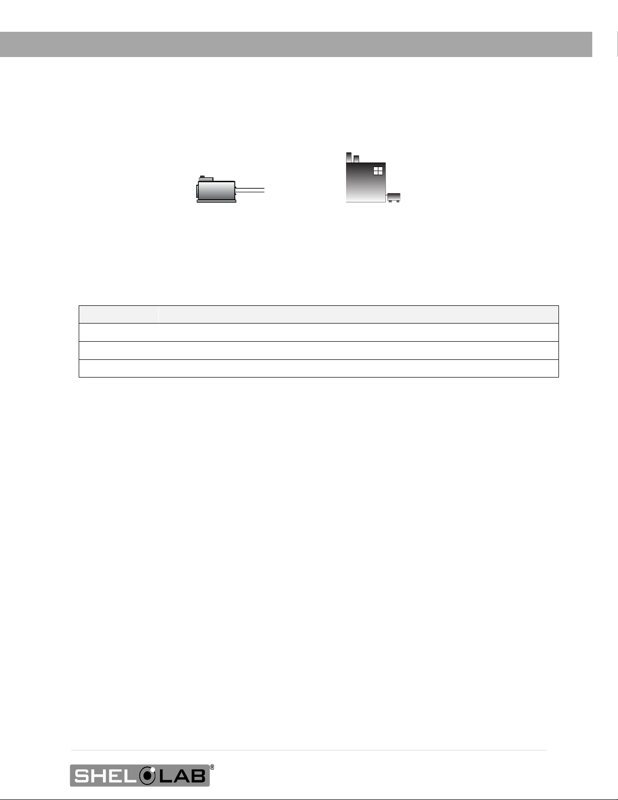
Building Vacuum Supply
Vacuum Pump
INTRODUCTION
VACUUM SUPPLY REQUIREMENTS
Pump or Building System Required
The oven does not come with a vacuum pump. A pump must be separately purchased for the oven.
Required Flow Rate
For the oven chamber door to seal, the vacuum pump or system must be able to evacuate at least 1
cubic foot per minute (cfm) for each cubic foot of oven chamber volume (CuFt).
Model Chamber Capacity Min. Pump Capacity CFM Min. Pump Capacity LPM
SVAC1 0.56 CuFt 1 cfm 28 Liters per Minute
SVAC2 1.67 CuFt 2 cfm 57 Liters per Minute
SVAC4 4.50 CuFt 5 cfm 142 Liters per Minute
The use of clamps to secure vacuum tubing is recommended.
Minimum Evacuation Level
The oven must be pumped down to -3 inHg or lower for the oven chamber door to seal. The manufacturer
recommends pumping down below -3 inHg as part of the first step in a baking recipe to ensure a good
seal. This helps safeguard the oven and pump.
Pump Type Selection
Consult a vacuum pump specialist to determine the pump type best suited to your baking application. The
correct selection of a vacuum pump is critical for evacuating the chamber to the level required for your
vacuum baking applications in a timely manner. The nature of the sample or product being heated should
drive the selection of the pump, including the types of chemicals outgassed during the baking process.
Common pump types include Chemical Duty PTFE Dry, Standard Duty Dry, and Compact Direct-Drive. The
selection of an application-specific pump can improve the overall oven performance and minimize pump
maintenance costs. All maintenance and instructional information should be obtained from the pump
manufacturer if not shipped with the pump.
Oil Trap Recommended
The use of an oil trap plumbed on the vacuum line between the oven and the pump is strongly
recommended. The trap protects the pump from any oils outgassed during your baking procedure. This
extends the life of the pump.
9 | Page
Page 10
Reference
INTRODUCTION
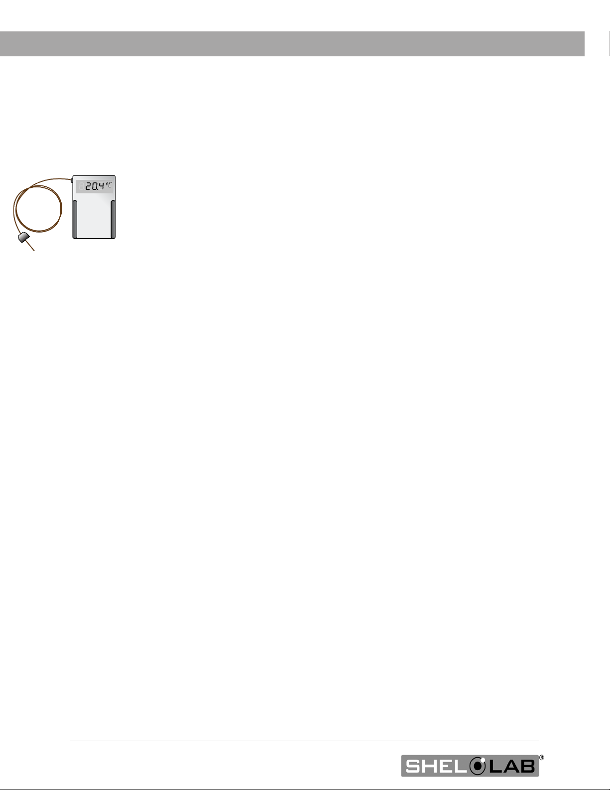
REFERENCE SENSOR DEVICE
Must be purchased separately
A reference sensor device is required for calibrating the unit temperature display.
Reference devices must meet the following standards:
• Accurate to at least 0.1°C
Device
Temperature Probes
Use a digital device with wire thermocouple probes that can be introduced into the unit chamber
through the unit access port. Select a probe suitable for the application temperature you will be
calibrating at.
A vacuum-rated feedthrough baseplate is required for introducing the probe through the KF-25 port.
Why Probes?
Reference readings taken outside the chamber using wire temperature probes avoid chamber door
openings. Openings disrupt the chamber temperature. Each disruption requires a minimum 1-hour wait
to allow the chamber to re-stabilize before continuing.
No Alcohol or Mercury Thermometers
Alcohol thermometers do not have sufficient accuracy to conduct accurate temperature calibrations.
Never place a mercury thermometer in the unit chamber. Always use thermocouple probes.
The device should be regularly calibrated, preferably by a third party.
10 | Page
Page 11

INTRODUCTION
OVEN CHAMBER GASKETS
Wear and Replacement
Chamber gaskets are non-warranty, high-wear consumable items subject to compression forces, heat,
and outgassed byproducts. Heavy usage rates may necessitate frequent replacements. The
manufacturer strongly recommends keeping a spare gasket on hand during operation.
Included Chamber Gasket
Each oven comes with a replaceable silicone gasket installed on the chamber liner, which seals the
oven chamber when the door is closed and the chamber is under vacuum. The gasket must be
replaced periodically and is rated to 230°C. It is vulnerable to acids and solvents. The manufacturer
also offers for sale Viton®, fluorosilicone, and Buna-N gaskets. See page 76 for information on gasket
type suitability for baking applications.
Do Not Use Vacuum Grease
• These ovens do not require vacuum grease to seal.
• The use of grease may contaminate the chamber and samples and can foul vacuum pumps.
• Silicone vacuum grease will damage silicone gaskets. Do not use silicone grease with
silicone gaskets.
11 | Page
Page 12

INTRODUCTION
12 | Page
Page 13
2 1 1
3 12 1 4
RECEIVING YOUR UNIT
INSPECT THE SHIPMENT
When a unit leaves the factory, safe delivery becomes the responsibility of the carrier. Damage
sustained during transit is not covered by the manufacturing defect warranty. When you receive
your unit, inspect it for concealed loss or damage to its interior and exterior. If you find any damage
to the unit, follow the carrier’s procedure for claiming damage or loss.
Save the shipping carton until you are certain that the unit and its accessories function properly.
1. Carefully inspect the shipping carton for damage.
2. Report any damage to the carrier service that delivered the unit.
3. If the carton is not damaged, open the carton and remove the contents.
4. Inspect the unit for signs of damage. See the orientation depictions on the next pages as a
reference.
5. The unit should come with an Installation and Operation Manual and a Temperature Program
Manual.
6. Verify that the correct number of accessories has been included.
7. Carefully check all packaging for accessories before discarding.
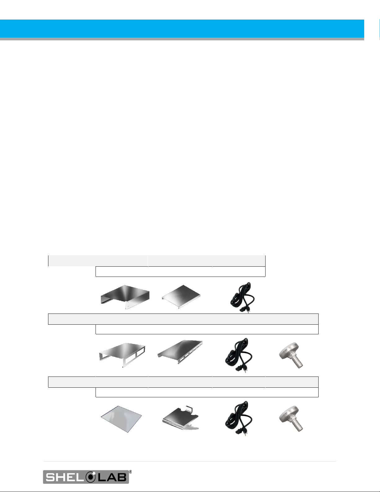
Included Accessories:
SVAC1 Tall Shelves Short Bottom Shelf Power Cord
SVAC2 Tall Shelves Short Bottom Shelf Power Cord Leveling Feet
2 1 1 4
SVAC4 Shelves Shelf Clips Power Cord Leveling Feet
13 | Page
Page 14
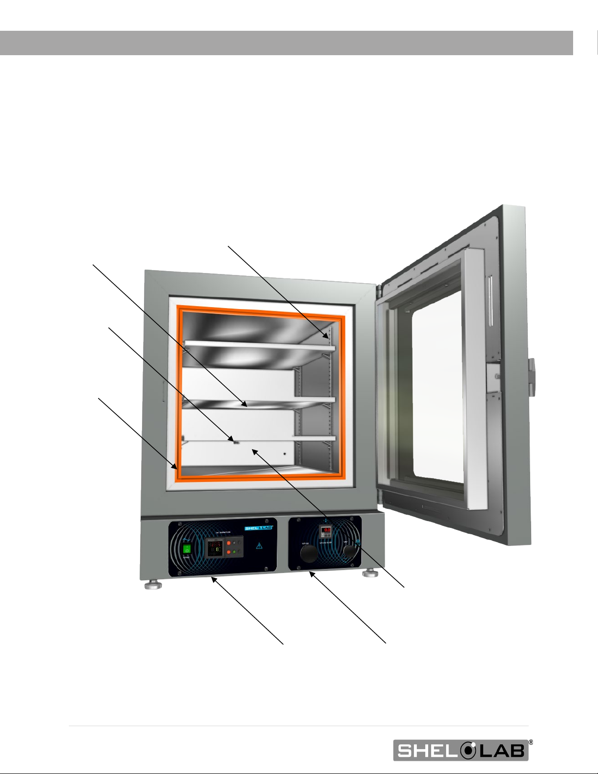
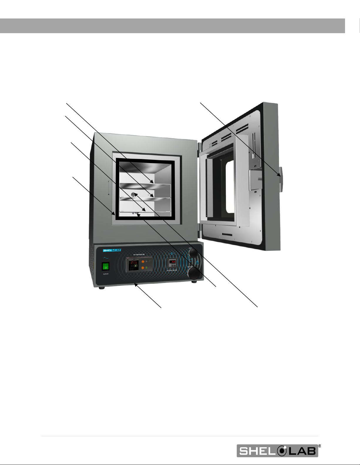
SVAC4
Chamber Door
Chamber
Oven Chamber
Shelf Standard Rail
Main Control Panel
Vacuum Control Panel
Temperature
Access Port (hidden
image)
RECEIVING
ORIENTATION
by the shelf in this
Probe
Gasket Seal
14 | Page
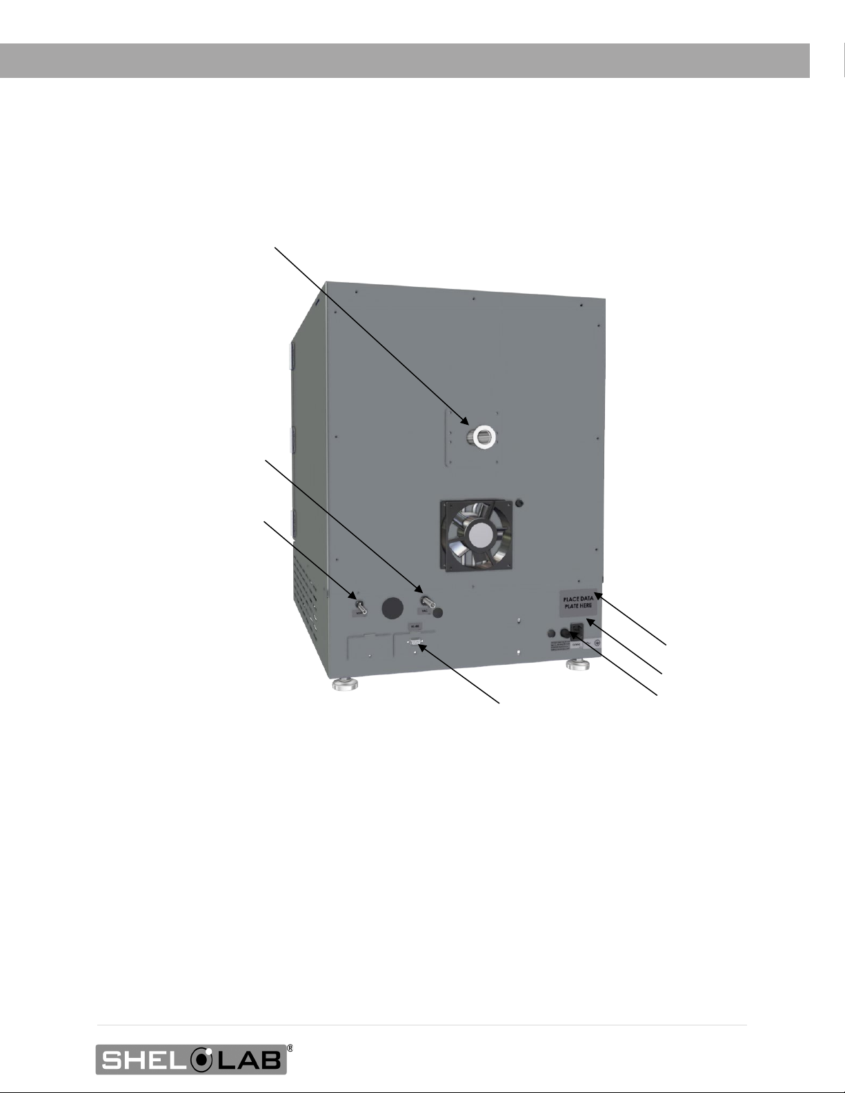
Page 15
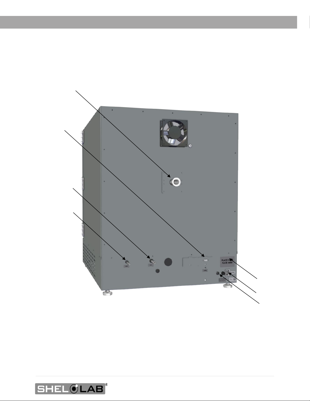
KF-25 Access Port (Includes Blank and Clamp, not pictured here)
Vacuum Port, 3/8
Chamber Vent
Power Cord
Fuse Holder
RS485 Data
Data Plate
RECEIVING
Port 9-Pin
Back of SVAC4
inch (9.52 mm)
Inlet Port ¼
inch (6.35 mm)
Inlet
15 | Page
Page 16
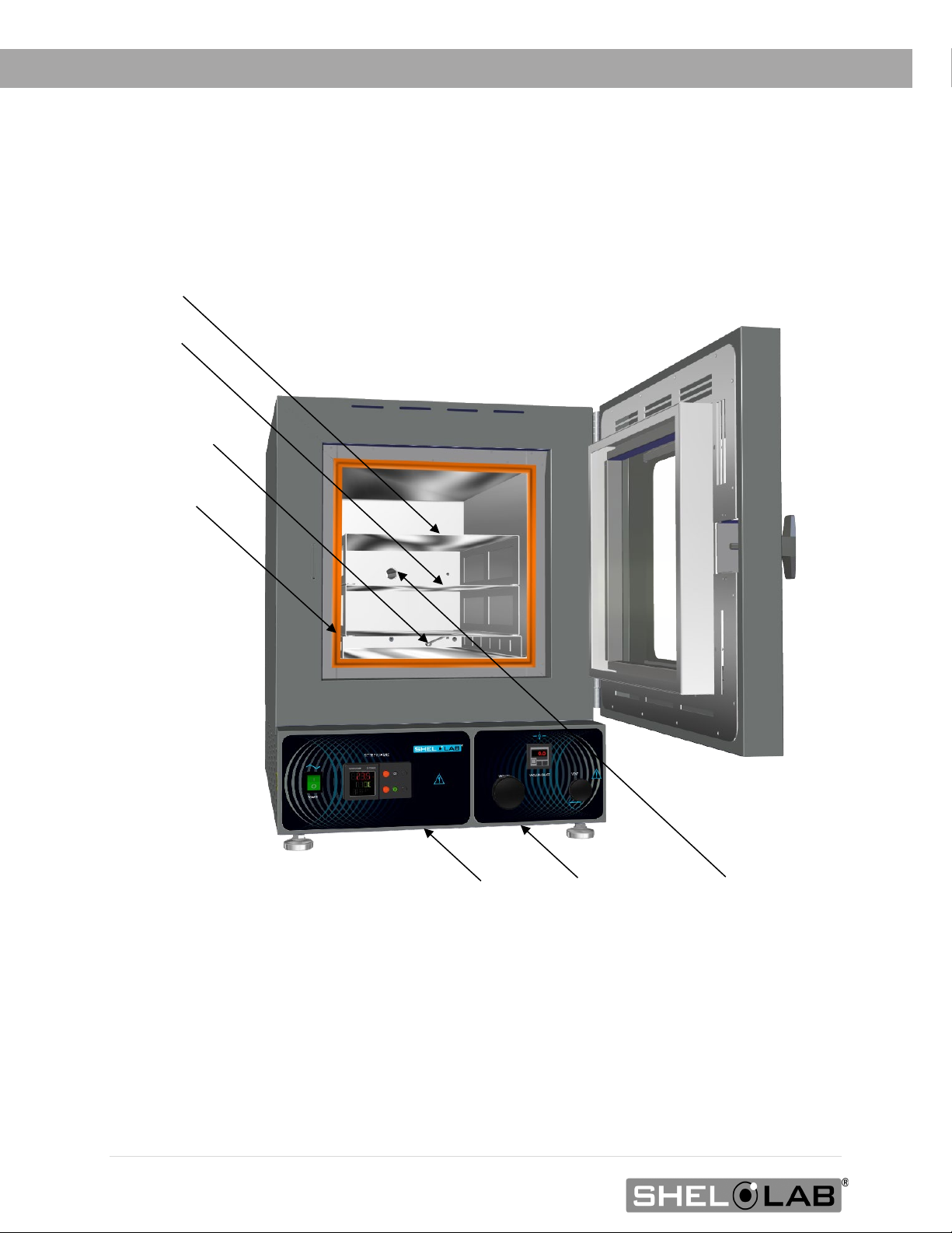
Temperature
the Short Shelf
Tall Shelf
Access Port
Tall Shelf
Chamber Door
Chamber
Main Control Panel
Vacuum Control Panel
RECEIVING
SVAC2
Probe Clip on
Gasket Seal
(KF-25 Fitting)
16 | Page
Page 17
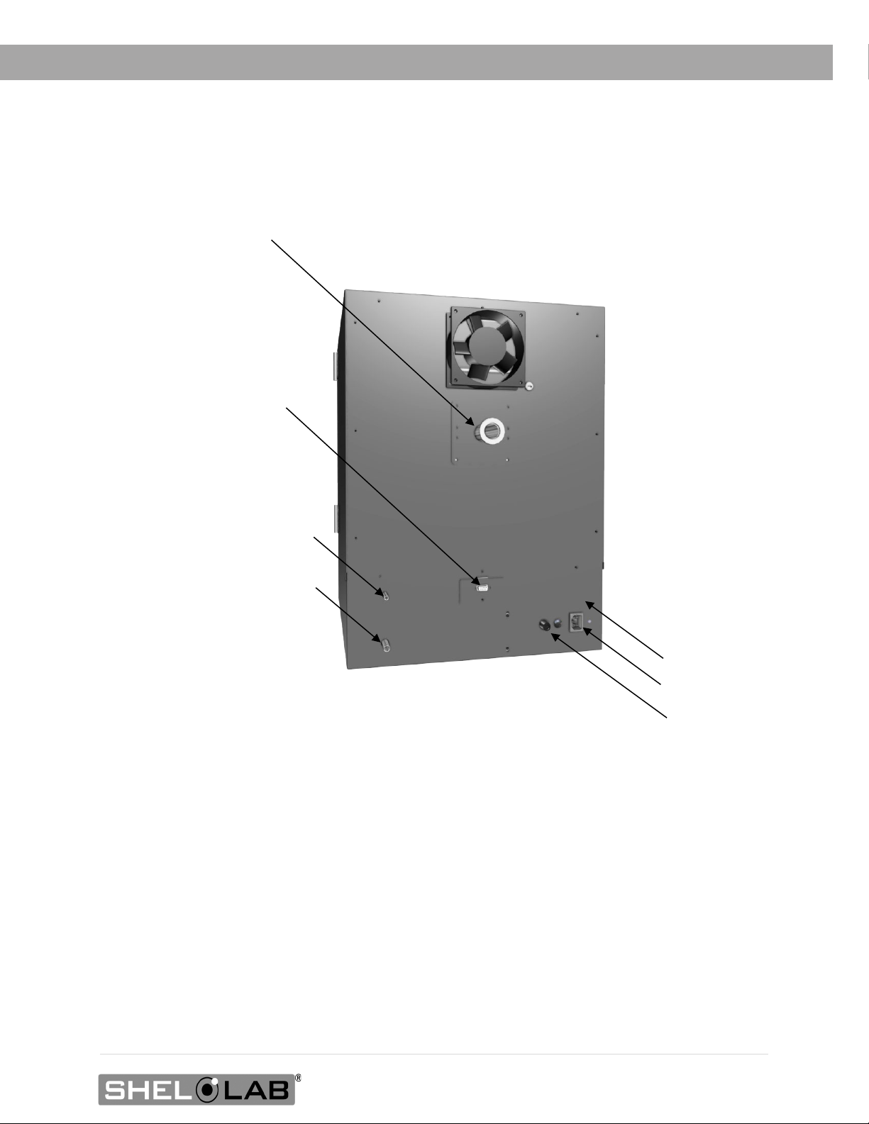
KF-25 Access Port (Includes Blank and Clamp, not pictured here)
Vacuum Port, 3/8
Chamber Vent
RS485 Data Port 9-Pin
Power Cord
Fuse Holder
Data Plate
RECEIVING
Back of SVAC2
inch (9.52 mm)
Inlet Port ¼
inch (6.35 mm)
Inlet
17 | Page
Page 18
Short Shelf
Tall Shelf
Access Port (KF-25 Fitting)
Door Latch
Tall Shelf
Chamber Door
Chamber
Control Panel
Temperature Probe Clip
RECEIVING
SVAC1
(Bottom)
Gasket Seal
18 | Page
Page 19
KF-25 Access Port (Includes Blank and Clamp, not pictured here)
Vacuum Port, 3/8
Chamber Vent
RS485 Data
Power Cord
Fuse Holder
Data Plate
RECEIVING
Port 9-Pin
Back of SVAC1
Inlet Port ¼
inch (6.35 mm)
inch (9.52 mm)
Inlet
19 | Page
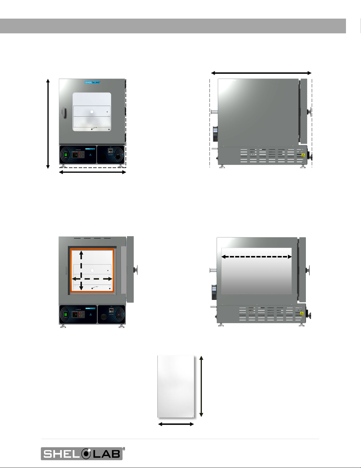
Page 20
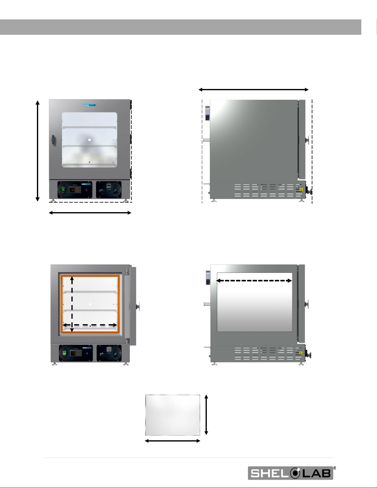
Shelf Width: 17.2 inches (437 mm)
Shelf Depth: 22.9 inches
Width: 27.0 inches (686 mm)
Depth: 35.2 inches (894 mm)
Exterior
Interior
Chamber Height: 18.0 inches (457 mm)
Chamber Width: 18.0 inches (457 mm)
Chamber Depth: 24.0 inches (610 mm)
Shelves
Height: 32.8 inches (833 mm)
RECEIVING
DIMENSION VISUALS
SVAC4
See page 26 for the required ventilation clearances.
20 | Page
(582 mm)
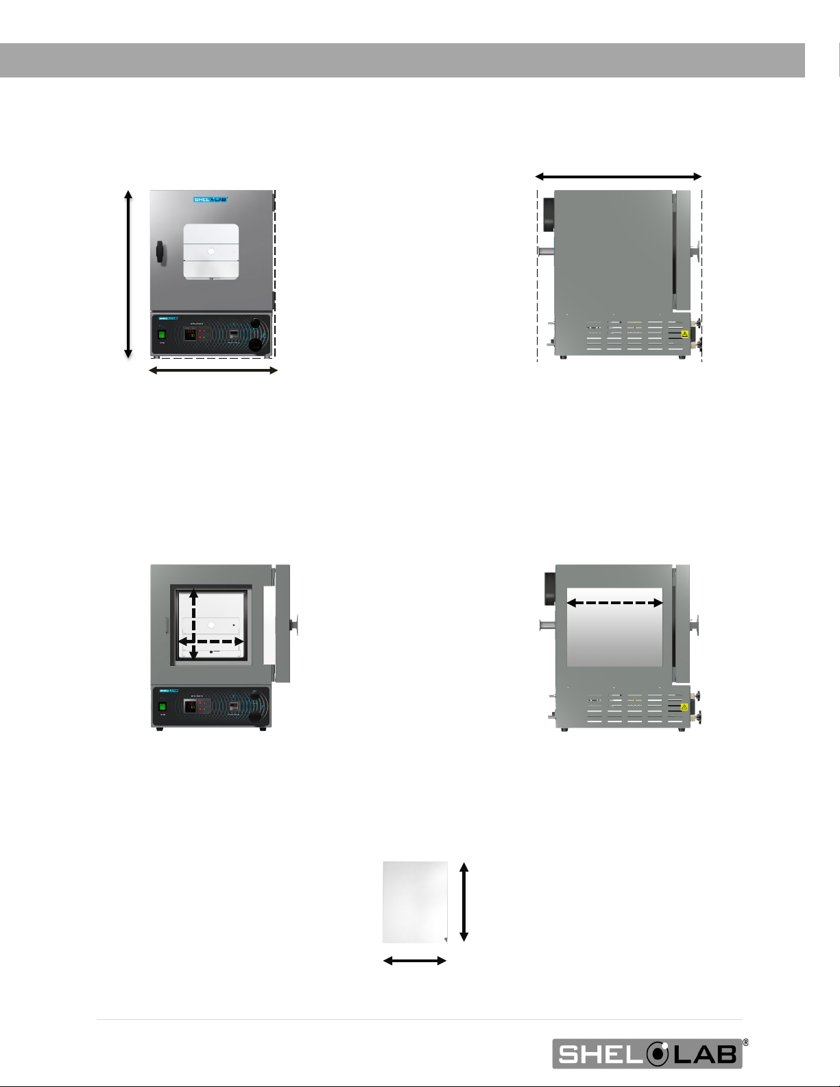
Page 21
Width: 20.8 inches (528 mm)
Exterior
Interior
Tall Shelves
Shelf Depth: 19.0 inches
Chamber Height: 12.0 inches (304 mm)
Chamber Width: 12.0 inches (304 mm)
Chamber Depth: 20.0 inches (508 mm)
Height: 26.8 inches (681 mm)
Shelf Width: 11.3 inches (223 mm)
Depth: 31.3 inches (795 mm)
RECEIVING
SVAC2
See page 26 for the required ventilation clearances.
(483 mm)
21 | Page
Page 22
Interior
Tall Shelves
Shelf Depth: 11.0 inches
Width: 17.5 inches (444 mm)
Chamber Height: 9.0 inches (228 mm)
Chamber Width: 9.0 inches (228 mm)
Chamber Depth: 12.0 inches (304 mm)
Height: 23.7 inches (602 mm)
Shelf Width: 8.8 inches (223 mm)
Depth: 23.0 inches (584 mm)
Exterior
RECEIVING
SVAC1
See page 26 for the required ventilation clearances.
22 | Page
(279 mm)
Page 23
RECEIVING
RECORD DATA PLATE INFORMATION
The data plate contains the unit model number, serial number, part number, and part ID. Tech
Support will need this information during any support call. Record it below for future reference.
• The data plate is located on the back of the oven, above the power cord inlet.
Data Plate Information
MODEL NO:
SERIAL NO:
PART NO:
PART ID:
23 | Page
Page 24

RECEIVING
24 | Page
Page 25

INSTALLATION
INSTALLATION PROCEDURE CHECKLIST
For installing the unit in a new workspace location.
Pre-Installation
Verify that a vacuum supply source suitable for your application is available
and can be connected to the oven, page
• See page 32 for the oven gas and vacuum port locations.
Check that the required ambient conditions for the unit are met, page 26.
Check that the spacing clearance requirements are met, page 26.
9.
• Unit dimensions may be found on page 71.
Check that a suitable electrical outlet and power supply is present, page 27.
Install the oven in a suitable workspace location
Review the lifting and handling instructions, page 28.
SVAC2 and SVAC4, install the leveling feet, page 28.
Install the oven in its workspace location, page 29.
Set up the oven for use
Clean the oven shelving. Clean the chamber if needed, page 29.
Install the shelving in the oven chamber, page 30.
Connect the oven to its vacuum supply source along with any optional backfill gas
supply, page
32.
25 | Page
Page 26

6” (152 mm) Fan
KF-25 Port
6” (152 mm)
Door Swing
12” (305 mm)
12” (305 mm)
12” (305 mm)
6” (152 mm)
SVAC1: 17.6” (447 mm)
INSTALLATION
REQUIRED AMBIENT CONDITIONS
This oven is built for use indoors at room temperatures between 15°C and 40°C (59°F and 104°F), at no
greater than 80% Relative Humidity (at 25°C / 77°F). The ambient temperature should not change by
2°C (3.6°F) or more during operation.
Operating outside these conditions may adversely affect the oven temperature performance.
When selecting a location to install the unit, consider all environmental conditions that can adversely
impact its temperature performance. These include:
• Proximity to other ovens, autoclaves, and any device that produces significant radiant heat
• Heating and cooling vents or other sources of fast-moving air currents
• High-traffic areas
• Direct sunlight
REQUIRED CLEARANCES
These clearances are required to provide airflows for ventilation and cooling.
6 inches (152 mm) of clearance is required on the sides.
SVAC2: 20.8” (528 mm)
SVAC4: 27.0” (686 mm)
12 inches (305 mm) of headspace clearance is required between the top of the unit and any
overhead partitions.
Do not place objects on top of the oven.
A KF-25 vacuum port is located on the back of the oven for introducing vacuum-rated thermocouple
feedthroughs into the chamber or connecting to an external vacuum supply source. Leave sufficient
clearance for users to safely access this port.
26 | Page
Page 27

INSTALLATION
POWER SOURCE REQUIREMENTS
When selecting a location for the unit, verify each of the following requirements is satisfied.
Power Source: The wall power outlet must meet the power requirements listed on the unit data
plate.
Model AC Voltage Amperage Frequency
SVAC1
110 – 120 7.0 50/60 Hz
SVAC2 110 – 120 10.0 50/60 Hz
SVAC4 110 – 120 13.0 50/60 Hz
• Supplied voltage must not vary more than 10% from the data plate rating. Damage to the
unit may result if the supplied voltage varies more than 10%.
• The wall power source must be protective earth grounded.
• Use a separate circuit to prevent loss of the unit due to overloading or circuit failure.
• The recommended wall circuit breakers for these units are 15 amps.
• The wall power source must conform to all national and local electrical codes.
Power Cord
The unit must be positioned so that all end-users can quickly unplug the oven in the event of an
emergency.
• Each unit comes provided with a 125-volt, 15-amp, 9ft 5 in (2.86 m) NEMA 5-15P power
cord.
• Always use this cord or an identical replacement.
Fuses
Each unit comes with a fuse installed in a fuse holder immediately adjacent to the power cord inlet.
• The fuse must be installed and intact for the unit to operate.
• Always find and fix the cause of a blown fuse prior to putting the unit back into operation.
• Fuse type:
o T16A 250V 5x20mm
27 | Page
Page 28

INSTALLATION
LIFTING AND HANDLING
The oven is heavy. Use appropriate lifting devices that are sufficiently rated for these loads. Follow
these guidelines when lifting the oven:
• Lift the oven only from its bottom surface.
• Doors, handles, and knobs are not adequate for lifting or stabilization.
• Restrain the oven completely while lifting or transporting so it cannot tip.
• Remove all moving parts, such as shelves and trays, and lock doors in the closed position
during transfers to prevent shifting and damage.
LEVELING
All ovens must be level and stable for safe operation.
SVAC2 and SVAC4: Install the 4 leveling feet in the 4 corner holes in the bottom of the oven.
Note: To prevent damage when moving the unit, turn all 4 leveling feet so that the leg of each foot
sits inside the unit.
SVAC1: The rubber leveling feet are non-adjustable.
28 | Page
Page 29

INSTALLATION
INSTALL THE OVEN
Install the unit in a workspace location that meets the criteria discussed in the previous entries of the
Installation section.
• Do not connect the oven to its power source at this time.
DEIONIZED AND DISTILLED WATER
Do not use deionized water to clean the unit, even if DI water is readily available in your laboratory.
• The use of deionized water may corrode metal surfaces and voids the manufacturing
warranty.
• The manufacturer recommends the use of distilled water in the resistance range of 50K
Ohm/cm to 1M Ohm/cm, or a conductivity range of 20.0 uS/cm to 1.0 uS/cm, for cleaning
applications.
INSTALLATION CLEANING AND DISINFECTING
The manufacturer recommends cleaning the shelving and oven chamber prior to the installation of
the shelving in the chamber. The unit was cleaned at the factory but may have been exposed to
contaminants during shipping.
• Remove all wrappings and coverings from shelving prior to cleaning and installation.
• See the 33TCleaning and Disinfecting33T topic in the User Maintenance section (see page 51) for
more information on how to clean the oven chamber and shelving.
• Do not clean with deionized water.
29 | Page
Page 30

INSTALLATION
SHELVING INSTALLATION
In a pumped down oven chamber, heat flows in part from oven elements through the chamber walls
and floor and into the shelves. Install the shelves as described below to ensure proper heat
conduction and temperature measurement in a vacuum environment.
Never place samples or products on the oven chamber floor. The floor runs hotter than the shelf
temperatures. All oven heating specifications are for shelving temperatures.
SVAC1 and SVAC2
Temperature Probe Shelf Clip
Bottom of Short Shelf
1. Carefully slide the short shelf into position on the chamber floor, sliding the clip on the bottom
of the shelf onto the oven temperature probe.
• The shelf clip should be on the side of the shelf closest to the oven door. This ensures
the best measurement position for the probe.
• The oven probe extends from the back wall near the floor of the chamber.
• The short shelf must be on the bottom of the shelf-stack to ensure the oven
accurately measures and controls the shelving temperature.
2. Place the 2 tall shelves on top of the short shelf.
Continued on next page
30 | Page
Page 31

Rocking Motion
Probe
Shelf
Install 4 Shelf Clips
Place the Shelf
INSTALLATION
Shelving Installation Continued
SVAC4 Shelving
To ensure accurate temperature measurement, one shelf bottom must be in close proximity to the
oven temperature probe. This probe extends out from the chamber back wall. Do not place the
shelf in direct contact with the probe.
1. Install the shelf clips in the slots of the shelf standard mounting rails located on the sides of the
chamber interior, 4 clips per shelf.
a. Squeeze each clip, insert the top tab first, and then the bottom tab using a
rocking motion.
2. Set the shelves on the clips.
a. Verify the shelves are level.
31 | Page
Page 32

KF-25 Vacuum Port
Vacuum Line Connected
to the 3/8 inch Vacuum
Port
1. Vacuum Supply: Connect
Optional: Connect a
INSTALLATION
CONNECT TO THE VACUUM SUPPLY
Use clamps to secure the tubing to the Vacuum and Vent Ports.
to the 3/8 inch (9.52 mm)
Vacuum Port.
clean gas supply to the
Vent Port (Backfill Inlet).
The maximum allowed
gas pressure is 15 psi.
Oven Chamber Ports – Left to Right
• Vent Port (Backfill Inlet) – 1/4 inch (6.35 mm) OD
o External atmosphere backfills the oven chamber through this port when the Vent
Valve control on the front control panel is opened.
o A clean or inert gas supply source may be connected to this port. The maximum
allowed delivery pressure at the port is 15 psi.
• Vacuum Port – 3/8 inch (9.52 mm) OD
o The chamber atmosphere is evacuated through this port. Connect the vacuum
source to the oven here.
o This port is opened and closed by the Vacuum Valve control on the front control
panel.
• KF-25 Vacuum Port
o Comes with a clamp and blank.
Vacuum and Gas Backfill Connections
32 | Page
o Used for introducing thermocouple probes through a vacuum-rated feedthrough.
o A vacuum supply can be connected to the KF-25 port for increased efficiency in
vacuuming down the chamber. However, the Vacuum Valve control on the front
control panel will not affect the level of vacuum and must be set to Closed to
prevent atmosphere from entering the chamber through the 3/8-inch Vacuum Port.
Page 33

GRAPHIC SYMBOLS
The unit is provided with graphic symbols on its exterior. These identify hazards and adjustable
components as well as important notes in the user manual.
Symbol Definition
Consult the user manual
Consulter le manuel d'utilisation
Over Temperature Limit system
Thermostat température limite contrôle haute
AC Power
Repère le courant alternatif
I/ON O/OFF
I indique que l'interrupteur est en position marche.
O indique que le commutateur est en position d'arrêt.
Potential shock hazard
Risque de choc électrique
Recycle the unit. Do not dispose of in a landfill.
Recycler l'unité. Ne jetez pas dans une décharge
Protective earth ground
Terre électrique
33 | Page
Page 34

SYMBOLS
34 | Page
Page 35

Top Line (Red): Present chamber shelving
CONTROL OVERVIEW
Control Panels
Power Switch
The switch illuminates when in the ON ( I ) position.
Temperature Controller - Display on Homepage
While on the homepage, the Up and Down arrow buttons adjust the constant temperature setpoint.
Pressing and holding both buttons navigates from the homepage to menu pages. On the menu
pages, the buttons adjust calibration offsets and temperature program variables.
When starting on the homepage, the green Advance button navigates forward through parameter
option pages including and Units of Measurement (Celsius or Fahrenheit). The button also advances
forward in menus and parameter lists when programming a temperature recipe in the oven
controller.
The gray Reset button returns the display to the previous page or menu. Pushing the Reset button
repeatedly returns the display to the homepage.
temperature
Middle Line (Green): The constant
temperature setpoint
Bottom Line: Flashing “2” indicates active
heating
The EZ1 button launches temperature Program 1. Pushing EZ1 again while running aborts Program 1.
The EZ2 button launches temperature Program 2 (Step 11). Pushing EZ2 again while running aborts
Program 2.
35 | Page
Page 36

Close
Close
CONTROL OVERVIEW
Vacuum Gauge
As set at the factory, this gauge shows the chamber vacuum level relative to sea level
atmospheric pressure in inches of mercury (inHg). The display range is 0 to -29.9inHg. Zero
is the room atmosphere pressure at sea level and -29.9inHg a near-perfect vacuum. See
page 48 for how to display other units of measurement or zero the gauge to your local
altitude.
Vacuum Valve Control
This valve adjusts the level of vacuum draw applied to the oven chamber through the
Vacuum Port on the back of the oven.
• In the open position, this valve allows the connected vacuum supply to pump down
the oven chamber.
• In the closed position, the valve closes off the vacuum draw.
This valve should always be closed before a vacuum pump attached to the oven is turned off.
This safeguards the pump from external atmosphere being drawn through it and into the oven. If
an attached oil pump is turned off while the valve is open and the chamber is under vacuum, oil
may be pulled out of the pump and into the oven.
Vent Valve Control (Chamber Backfill)
This valve controls the oven chamber inlet Vent Port on the back of the oven.
• In the open position, the oven chamber is open to external atmosphere through the
vent intake port on the back of the oven.
• Optional: An inert or clean backfilling gas supply connected to the Vent Port will
flow gas from the pressurized supply to the oven chamber when the Vent Valve is
open.
• When the valve control is in the closed position, the chamber is cut off from external
atmosphere and any backfill gas supply.
o The vent must be closed before pumping down the chamber. Failure to
do so may result in damage to the vacuum pump.
36 | Page
Page 37

OPERATION
Safe operation of the oven depends on the actions and behavior of the oven end-user. Operating
personnel must read and understand the Operating Precautions in this section prior to operating
the oven. The end-user must follow these instructions to prevent injuries and to safeguard their
health, environment, and the materials being treated in the oven, as well as to prevent damage to
the oven. Failure to adhere to the Operating Precautions, deliberately or through error, is a
hazardous behavior on the part of the end-user.
Le fonctionnement sûr du four dépend des actions et du comportement des opérateurs du four. Le
personnel d'exploitation doit lire et comprendre les consignes de sécurité et les précautions
d'utilisation de cette section avant d'utiliser le four. Les opérateurs doivent suivre ces instructions
pour prévenir les blessures et protéger leur santé, leur environnement et les matériaux traités dans
le four, ainsi que pour éviter d'endommager le four. Le non-respect des consignes de sécurité et des
précautions d'utilisation, délibérément ou par erreur, est un comportement dangereux de la part de
l'opérateur.
OPERATING PRECAUTIONS
• Do not use this oven in unsafe improper applications that produce flammable or combustible
gases, vapors, liquids, or fuel-air mixtures in quantities that can become potentially explosive.
• Outgassed byproducts may be hazardous to or noxious for operating personnel. Vacuum
pump exhaust should be vented to a location outside the workspace in a safe manner in
accordance with all applicable laws, ordinances, and regulations. Do not operate the oven in
an unsafe area with noxious fumes.
• Do not use this oven for applications heating hazardous fibers or dust. These materials can
become airborne and come into contact with hot surfaces.
• Individual ovens are not rated to be explosion proof. Follow all building certification
requirements and laws for Class I, II, or III locations as defined by the US National Electric
Code.
• The bottom surface of the chamber should not be used as a work surface. It runs hotter than
the shelf temperatures. Never place samples or product on the oven chamber floor.
• Do not place sealed or filled containers in the oven. These may burst open when the
chamber is under vacuum.
• Do not place alcohol or mercury thermometers in the oven. With improper use, they can
rupture.
• Do not move the oven until it has finished cooling.
Burn hazard: Use proper personal protective equipment to minimize the risk of burns when the oven door
is open and the chamber door interior, chamber surfaces, and shelving are hot.
Risques de brûlure: Utilisez un équipement de protection individuelle approprié pour minimiser le
risque de brûlures lorsque la porte du four est ouverte et que l'intérieur de la porte de la chambre, les
surfaces de la chambre et les étagères sont chauds.
37 | Page
Page 38

OPERATION
THEORY OF OPERATION
Vacuum
Vacuum is supplied by an external vacuum supply (a pump or building system) connected to the
vacuum port on the back of the oven. Vacuum levels obtained in the oven chamber are dependent
on pump type and performance, valve settings, and the nature of the application or process,
including the volume of materials outgassed.
The chamber atmospheric pressure is displayed on the Vacuum Gauge on the main control panel.
The chamber should be sealed and evacuated at the start of a vacuum baking application. The oven
is not built to operate with the chamber exposed to atmosphere. Running the oven with the door or
the vent open risks destroying the vacuum pump, damaging the integrity of the oven chamber, and
may oxidize chamber surfaces.
Vacuum pumps and door gaskets should be selected on the basis of the application type or process.
Pumps vary in suitability and safety depending on the outgassed byproduct types and moisture
levels produced in the oven chamber. Gasket types are both resistant to and vulnerable to different
chemicals.
Gas Backfill
A gas or clean air supply can be connected to the vent port (backfill inlet) or KF-25 port located on
the back of the oven. Nitrogen or other inert gases are typically used to avoid particulate
contamination or the oxidation of product that has not cooled down. The maximum allowed backfill
pressure is 15 psi of delivery at the port.
Heating Options
The oven can either heat to and run at a constant temperature setpoint or execute a programmable
multistep temperature program with ramp up, heat soak, and ramp down intervals.
38 | Page
Page 39

OPERATION
Heating in a Vacuum
In conventional ovens, powered elements transfer heat into the chamber air. The heated air then
circulates by natural convection or blower fan action and surrounds the product on the shelves,
gradually bringing it to temperature. In a vacuum oven, heat transfer takes place in part through
direct infrared radiation. A significant portion, however, takes place through conduction. The oven
heating elements located inside the chamber walls and floor transfer heat to the shelves via metalon-metal conduct. Each shelf then transports heat to the products or samples resting on it.
The displayed oven temperature may change when pumping down the oven. This reflects the
chamber probe transitioning from measuring air temperature to shelf temperature, followed by a
redistribution of thermal energy in the vacuum environment. This may present as a drop in
temperature followed by an apparent rise. The drop may take place even if the oven is actively
heating.
Heating Control
The controller monitors the oven chamber shelving temperature using a thermocouple temperature
probe extending into the chamber from the back wall. In a vacuum environment, the probe senses
the temperature of the shelf placed immediately above it. Placement of a shelf in close proximity to –
but not in contact with the probe — is crucial for accurate measurement of the shelving temperature
in the vacuum chamber.
The unit uses Proportional – Integral – Derivative (PID) control to avoid significantly overshooting the
setpoint. The rate of heating will slow as the chamber temperature approaches the target temperature. If
the chamber temperature is above the setpoint, the unit uses minimum heating to control the rate of
cooling and avoid dipping below the setpoint.
PID loops also optimize heating rates to compensate for the temperature environment around the
unit. If the unit is operating in a cool room, the controller will increase the length of the heating
pulses. Likewise, when operating in a warm room the unit uses shorter pulses. If the ambient
temperature conditions change significantly, there may be minor over or undershoots as the unit
adapts.
The oven relies on natural heat radiation for cooling. It can achieve a low-end operating temperature
of the ambient room temperature plus the oven waste heat.
High Limit Control System
The temperature controller contains a heating cutoff system with independent circuitry connected to a
redundant solid-state temperature sensor probe inside the oven chamber. This high limit system depowers
the oven heating elements whenever the chamber shelving temperature exceeds the current limit setting.
This safeguards the oven in the event of a failure of the main temperature control circuitry or main
temperature sensor probe.
The high limit is set by the end-user to a minimum of 10˚C above the highest temperature of the application
process the oven is currently being used for. Failure to set the high limit control system voids the oven
manufacturing defect warranty in the event of an overtemperature event.
39 | Page
Page 40

1.
Attach the Power Cord
3. Verify the Door and Valves are Closed
4. Turn on the Oven
Place the oven Power Switch in the ON ( I ) position.
5. Set the High Limit Temperature
6.
OPERATION
PUT THE OVEN INTO OPERATION
Perform the procedures below after the unit has been installed in a new workplace location. These
verify the integrity of the vacuum system and prepare the oven for normal use.
2.
Attach the power cord that came with the unit to the power inlet
receptacle on the back of the oven.
Plug the power cord into the workspace electrical supply.
Verify the oven chamber door is closed and latched, and
that the vent intake valve and vacuum valve are in the
closed position (turned all the way clockwise).
This safeguards your vacuum pump from exposure to
streaming atmosphere.
• The controller display will illuminate and default to its
homepage.
• The vacuum display will illuminate.
Plug in the Vacuum Pump
40 | Page
Use the 33TSet the High Temperature Limit procedure on33T
page 42 to set 33Tto the Limit heating cutoff at least 10°C above
the highest intended temperature of your application33T.
Plug the vacuum pump power cord into a wall power source.
Continued next page
Page 41

7.
8.
Setting the Operating Temperature
OPERATION
Continued from the previous page
Verify Vacuum Integrity
10 Minutes Minimum
Use the 33TEvacuating the Chamber33T procedure on page 43 to
pump down33T and hold the oven chamber under vacuum 33Tfor 10
minutes to verify the integrity of the vacuum supply system.
Read these procedures and descriptions.
33TSet the constant temperature setpoint33T. See the
procedure on page 45.
Or
33TProgram multistep heating recipes33T. See the
description on page 45.
The oven is now ready for use
41 | Page
Page 42

1.
OPERATION
SET THE HIGH TEMPERATURE LIMIT
Note: Test the high limit system once per year for functionality.
Set the high-temperature limit at least 10°C above the highest temperature the oven will run at during
your recipe program or constant-temperature application. See the High Temperature Limit system
explanation on page 39.
Advance to the Limit High Setpoint, starting on the homepage
Push Advance
Multiple Times
Push the Advance button until “Lh.S1” (Limit High
Setpoint) shows in the green mid-level display line.
2. Adjust the high limit to at least 10°C above the highest temperature of your application
Adjust
• The oven will automatically save and apply the
new High Limit setting after you have stopped
adjusting.
Note: If you are just checking the current hightemperature limit setting, push the Reset button to
exit the Limit High Setpoint menu and return to the
homepage without saving any changes.
3. Return to the homepage
Push Reset
•
Returned to homepage
End of Procedure
42 | Page
Page 43

Evacuate the Oven Chamber
1. Verify the Vacuum and Vent Valve controls are in the closed position
3. Open the oven Vacuum Valve
4. Close the Vacuum Valve
Turn the Vacuum Valve control back to the closed position (clockwise) to
• The pump may remain on.
VACUUM
VENT
VACUUM
OPERATION
EVACUATING AND BACKFILLING THE OVEN CHAMBER
The oven chamber must be drawn down to at least -3 inHg (-76 mmHg or -10 kPa) in order to seal.
Option 1: Vacuuming down with a pump connected to the vacuum port.
• This protects your vacuum pump from exposure to streaming
atmosphere.
2. Turn on your vacuum pump
Turn the control all the way counterclockwise.
• The Vacuum Gauge on the front panel should
show the chamber pressure decreasing.
• The achievable vacuum level is dependent on
altitude above sea level as well as the vacuum
supply efficiency and the volume of outgassed
byproducts. See page 49.
Holding at Vacuum
Continue evacuating the chamber throughout the baking application
to vent outgassed byproducts.
Backfilling the Oven Chamber
protect the vacuum pump from extended exposure to streaming
atmosphere.
5. Slowly open the Vent Valve
The chamber pressure gauge will count upward to 0 inHg.
End of Procedure
43 | Page
Page 44

Evacuate the Oven Chamber
1. Verify the Vacuum and Vent Valve controls are in the closed position
3. Open the regulator on your vacuum supply system
4. Close the regulator on your vacuum supply system.
The chamber pressure gauge will count upward
VENT
OPERATION
Option 2: Vacuuming down with a vacuum supply connected to the KF-25 fitting on the
back of the oven.
2. Turn on your vacuum pump
• This protects your vacuum pump from exposure to streaming
atmosphere.
• The vacuum gauge should show a decreasing
pressure in the oven chamber.
Holding under Vacuum
• Continue evacuating the chamber throughout the baking
application to vent outgassed byproducts.
• When first putting the oven into operation, hold under
vacuum for at least ten minutes.
Backfilling the Oven Chamber
• This isolates your pump from the oven chamber.
5. Slowly open the Vent Valve
•
to 0 inHg.
End of Procedure
44 | Page
Page 45

1.
2.
OPERATION
SETTING THE CONSTANT TEMPERATURE SETPOINT
Adjust the constant temperature setpoint on the homepage
• Stay 10°C below the high
limit setpoint.
Note: Holding down an arrow
button will cause the temperature
to advance in increments of ten
Adjust
Release the arrow buttons after adjusting the setpoint
(10).
• There may be a brief pause as the oven controller
calculates the optimum power usage to achieve the
setpoint starting from the current oven chamber
temperature.
• A small illuminated 2 near the bottom of the display
indicates the temperature controller is calling for
heat.
Oven Heating
TEMPERATURE PROGRAMS
Please see the temperature program manual included with this oven for how to program automated
heating recipes. The manual provides illustrated explanations for all major program functions and
programming steps.
Pushing EZ1 launches heating Program 1. Pushing EZ1 again while running aborts Program 1.
Pushing EZ2 launches heating Program 2 (Step 11). Pushing EZ2 again while running aborts Program 2.
45 | Page
Page 46

OPERATION
HIGH TEMPERATURE LIMIT ACTIVATED
The High Limit system cuts off heating in the oven whenever the chamber temperature meets or
exceeds the Limit setting. Heating remains disabled until the oven end-user clears the Limit cutoff.
Indicators
When heating is cut off, the oven display flashes an alert screen alternating with
the homepage. Additionally, an illuminated “4” on the bottom display level
specifies that the oven should be routing electricity away from the heating
elements.
Activation of the Limit cutoff is accompanied by a click sound.
Possible Causes of High Limit Activation
• The oven temperature is set above or near the High Limit cutoff setting. The
High Limit should be set at least 10°C above the highest intended
temperature of your heating application.
• A heat source in the oven chamber is pushing the oven temperature above
the limit setting.
• Significant outgassing in the chamber may be interfering with the measured
temperature.
• Attempting to heat a significant mass of product or samples may trigger a
temperature overshoot and subsequent Limit cutoff.
• The oven temperature controller circuitry or sensor probe have failed.
Alternating Screens
Attention Screen
Heating Off
If you suspect an ignition event in the oven chamber or a hardware failure wait for the oven to
cool to room temperature before opening the chamber door. Contact
33TTechnical Support33T for
assistance.
Clearing the High Limit Heating Cutoff
• Clearing the cutoff restores power to the oven heating elements.
• The oven chamber temperature must be below the High Limit cutoff setting before
clearing the cutoff.
• Always verify it is safe to resume heating before clearing the High Limit cutoff.
1. Push the Reset button.
• The alert screens will flash 2 additional times before the oven controller clears the
cutoff, ending it.
46 | Page
Page 47

X5
⁰C ⁰F
OPERATION
CHANGING THE UNIT OF MEASUREMENT
The controller can display temperatures in either Celsius or Fahrenheit.
1. Starting on the homepage, push the green Advance button until
reaching the “C_F1” units of measurement option.
2. Use the Arrow buttons to change the measurement parameter on
the top display line to your preferred unit of measurement.
• “C” is Celsius and “F” Fahrenheit.
3. Push the Reset button to save and return to the homepage.
47 | Page
Page 48

Inches of Mercury
Kilopascals
Both
OPERATION
VACUUM GAUGE OPERATIONS
Change the Unit of Measurement
1. Place the vacuum gauge in its adjustment mode.
a. Press and hold the “M” button for approximately 3 seconds.
• The display will begin to blink and show a unit of measurement.
2. Use the arrow buttons to scroll between units.
3. Exit the adjustment mode.
a. Press and hold the “M” button for approximately 3 seconds.
• The display will cease blinking and show the current chamber
pressure.
Units of Measurement – Display Characters
kPa Kgf/cmP2 bar psi mmHg inHg mmHR
Zeroing the Gauge
As set at the factory, the vacuum gauge shows a reading of 0 inches of mercury (inHg) when the
chamber is at ambient (room) pressure. The display was set near sea level.
If the gauge does not show 0 inHg when the chamber is at room atmospheric pressure, perform the
following steps to zero the gauge.
1. With the chamber door open, press and hold both the Up and Down
arrow buttons.
RO
2
See page 72 for the zero equivalent for units of measurement other than inHg.
48 | Page
2. Release the buttons when the display shows 0.0.
Page 49

Sea Level
Sea Level
14.70 psi
-29.9 inHg
1000ft
305m
14.16 psi
-28.9 inHg
2000ft
610m
13.66 psi
-27.8 inHg
3000ft
914m
13.16 psi
-26.8 inHg
6000ft
1829m
11.77 psi
-24.0 inHg
7000ft
2134m
11.33 psi
-23.1 inHg
8000ft
2438m
10.91 psi
-22.2 inHg
10,000ft
3048m
10.10 psi
-20.6 inHg
28.9590
98.0665
1
0.9806
14.2233
735.55
10000.27
29.5300
100
1.0197
1
14.5037
750.06
10197.44
0.0028
0.0098
0.0001
0.0001
0.0014
0.0029
1
OPERATION
MAXIMUM OBTAINABLE VACUUM
The maximum vacuum obtainable, as measured by the oven gauge, is in part a function of altitude.
While a vacuum pump will evacuate the same percentage of atmosphere from the oven chamber at
higher altitudes, less overall pressure is expelled because of the reduced density.
Put differently, at sea level, there are 29.9 inches of mercury pressure that can be drawn out of the
oven chamber by a vacuum pump. At 5000ft (1524m), there are only 24.9 inches of atmospheric
pressure to be evacuated from the oven chamber.
Altitude (Feet) Altitude (Meters) Atmospheric Pressure
4000ft 1219m 12.68 psi -25.8 inHg
5000ft 1524m 12.22 psi -24.9 inHg
9000ft 2743m 10.50 psi -21.4 inHg
*In gauge pressure
PRESSURE UNITS CONVERSION CHART
Max Vac
Obtainable
InHg kPa Kgf/cmP2 bar psi mmHG mmHR
1 inHg
1 kPa
1 3.3863 0.0345 0.3386 0.4911 25.400 345.32
0.2953 1 0.0102 0.01 0.1450 7.5006 101.97
1 Kgf/cmP2
1 bar
1 psi
1 mmHG
1 mmHR
2
RO
2.0360 6.8947 0.0703 0.0689 1 51.7150 703.09
0.0394 1.3332 0.0014 0.0013 0.0193 1 13.5954
49 | Page
RO
2
Page 50

OPERATION
DATA PORT
9-Pin Port
The 9-pin RS485 data port, located on the back of the oven, connects to the oven temperature
controller. The port is primarily intended for updating the controller software but can be used for
data logging and graphical temperature recipe programming. Accessing the controller with a
computer requires a 9-pin RS485-to-USB converter cable and driver software.
Applications and Utility Software
• National Instrument LabView and Watlow SpecView — Temperature monitoring and data
logging in graphical user interface environments.
• Watlow’s EZ Zone™ Configurator — Programming temperature recipes in a drop-down
menu environment. Configurator can also be used to copy and save the controller
configuration file, which includes the currently programmed heating programs.
o Configurator is available for free on the Watlow website.
OVEN COOLDOWNS
The oven chamber is well insulated and requires a significant amount of time to cool down while
sealed and evacuated. Please see the Unit Specifications chapter for cooldown times.
• Introducing free atmosphere into the oven when the chamber temperature is above 100°C
risks oxidizing chamber surfaces.
R
• Backfilling the oven with N
R does not significantly increase the rate of cooling.
2
50 | Page
Page 51

USER MAINTENANCE
Warning: Disconnect the unit from its power supply prior to maintenance or cleaning of this unit.
Avertissement: Avant d'effectuer toute maintenance ou entretien de cet appareil, débrancher le cordon
secteur de la source d'alimentation.
CLEANING
If a hazardous material or substance has spilled in the unit, immediately initiate your site Hazardous
Material Spill Containment protocol. Contact your local Site Safety Officer and follow instructions per
the site policy and procedures.
• Periodic cleaning is required.
• Do not use spray-on cleaners or disinfectants. These can leak through openings and coat
electrical components.
• Do not use cleaners or disinfectants that contain solvents capable of harming paint coatings
or stainless steel surfaces. Do not use chlorine-based bleaches or abrasives; these will
damage the chamber liner.
• Consult with the manufacturer or their agent if you have any doubts about the compatibility
of decontamination or cleaning agents with the parts of the equipment or with the material
contained in it.
Warning: Exercise caution if cleaning the unit with alcohol or flammable cleaners. Always allow the
unit to cool down to room temperature prior to cleaning and make sure all cleaning agents have
evaporated or otherwise been completely removed prior to putting the unit back into service.
Avertissement: Soyez prudent lorsque vous nettoyez l'appareil avec de l'alcool ou des produits de
nettoyage inflammables. Laissez toujours refroidir l'appareil à la température ambiante avant le
nettoyage et assurez-vous que tous les produits de nettoyage se sont évaporés ou ont été
complètement enlevés avant de remettre l'appareil en service.
Oven Chamber Cleaning Guidelines
1. Disconnect the unit from its power supply.
2. Remove any removable chamber accessory items such as shelving if present.
3. Use 99% isopropyl alcohol to clean chamber surfaces and shelving. Apply using lint-free
wipes.
4. Take special care when cleaning around temperature sensor probes. Do not clean the
probes.
5. Clean all removable accessories and components.
6. Verify the cleaning alcohol has evaporated completely from all chamber surfaces and
accessories prior to reconnecting the unit to its power source.
51 | Page
Page 52

MAINTENANCE
Oven Exterior Cleaning Guidelines
1. Disconnect the unit from its power supply.
2. The manufacturer recommends cleaning the unit with a mild soap and water solution.
• Do not use abrasive cleaners, these will damage metal surfaces.
• Cleaning agents must be compatible with steel and powder coat paint surfaces.
• Do not use deionized water to rinse or clean with.
3. Rinse with distilled water and wipe dry with a soft cloth.
MAINTAINING ATMOSPHERIC INTEGRITY
Periodically, inspect the door latch, trim, catch, and gasket for signs of deterioration. Failure to
maintain the integrity of the door system shortens the lifespan of the unit.
The gasket should be replaced if it is dry, cracked, or otherwise showing a loss of elasticity.
ELECTRICAL COMPONENTS
Electrical components do not require maintenance. If the oven fails to operate as specified, please
contact your distributor or
33TTechnical Support33T for assistance.
VACUUM PUMP MAINTENANCE
Refer to the operation manual supplied with your vacuum pump for recommended maintenance
routine, such as oil levels, replacement of sorbent charge, and exhaust filter change-outs. Contact
your vacuum pump supplier if you do not have an operation manual.
STORAGE
To prepare the unit for storage, remove all shelves, dry the chamber completely, and disconnect the
power supply. Be certain that the door is positively locked in the closed position.
52 | Page
Page 53

Use non-marking, heat-resistant polyamide tape to
MAINTENANCE
CALIBRATING THE TEMPERATURE DISPLAY
Note: Performing a temperature display calibration requires a temperature reference device. Please
see the33T Reference Sensor Devices entry33T on page 10 for device requirements.
Temperature calibrations match the temperature display to the actual chamber temperature inside
the oven chamber. The actual chamber temperature is supplied by a reference sensor device.
Calibrations compensate for software drifts in the controller as well as those caused by the natural
material evolution of the sensor probe in the chamber space. Calibrate as often as required by your
laboratory or production protocol, or regulatory compliance schedule. Always calibrate to the
industry or regulatory standards required for your application.
A Suggested Calibration Set-Up
1. Introduce the reference device vacuum-rated
thermocouple probe feedthrough into the KF-25
port on the back of the oven.
• There must be at least 12 inches (305
mm) of wire in the chamber to prevent
heat sinking, which would result in a
false low temperature reading.
2. Position the probe in the chamber.
• Place the probe head as close as
possible to the geometric center
point of the chamber.
• The probe head must be in direct
contact with the shelf surface.
3. Secure the probe head in position with
the non-marking, heat-resistant tape.
hold the thermocouple probe in place. The oven
manufacturer recommends Kapton brand tape,
0.5 inches width (12.7 mm), 2 mil thickness.
4. Use the KF-25 clamp to secure the
feedthrough and seal the port.
5. Close and latch the oven door. The door must
be sealed to carry out an accurate calibration.
6. Evacuate the chamber to the vacuum level of
your application or baking process. The
chamber must be under vacuum to perform an
accurate calibration.
Probe head in direct contact with the shelf surface
53 | Page
Page 54

Begin Calibration
Suggested Calibration Procedure
1
2
152.0°C
150°C
2
149.1°C
150°C
-0.9
150°C
Start
Required Stability Period
Fluctuations
See the Unit Specifications
MAINTENANCE
7. The unit temperature must be stable in order to perform an accurate calibration.
• The temperature is considered stabilized when the oven chamber has operated at your
calibration temperature for at least 1 hour with no fluctuations greater than the specified
temperature stability of the oven (see the Unit Specifications chapter).
• The manufacturer recommends calibrating at your application temperature.
chapter for the oven Time to
Temperature heat up rates.
Once the chamber has stabilized, compare the reference
temperature device and chamber temperature display readings.
• If the readings are the same, or the difference between
the two falls within the acceptable range of your protocol,
the display is accurately showing the chamber
temperature. The Temperature Calibration procedure is
now complete.
• See the next step if a difference falls outside the
acceptable range of your protocol.
43TThe display requires a calibration adjustment43T.
• The difference between the reference device and the display is
an offset value.
• Examples of offset values:
Reference Sensor
Reading
(Exaggerated)
-OR-
Oven Temp.
Display
1 Hour Minimum
Reference Device
Set Temperature
Reference Device
Set Temperature
Offset
Value
54 | Page
148.0°C 150°C -2
Note the offset value for use in Step 5.
Continued next page
Page 55

3
4
is not unlocked.
5
6
7
x2
x3
MAINTENANCE
Calibration continued
Unlock the controller.
• See the Unlocking procedure on page 57.
Note: The temperature controller must be unlocked in order to
access the Operations menu and enter a calibration offset.
Navigate to the Operations menu after unlocking the
controller.
a. Press and hold both the Up and Down arrow buttons
simultaneously for approximately 5 seconds.
b. Release the buttons when “A1” appears on the top display
line and “oPEr” appears in the mid display line.
Note: The Operations menu will not appear if the controller
Operations Menu
Advance through the Operations menu options to the
Temperature Calibration offset parameter.
a. Push the green Advance button repeatedly until “i.CA”
appears in the green mid display line and a number
value in the red top line.
Adjust the number value in the top display line to match the
offset value from step 2, using the arrow buttons.
Save the calibration offset and return to the homepage.
a. Push the Reset button 3 times so the display shows the
homepage.
• The oven will now begin heating or passively cooling to reach
the setpoint with the corrected display value.
Continued next page
55 | Page
Page 56

8
9
10
MAINTENANCE
Calibration continued
Wait for 30 minutes for the oven to stabilize, after the oven
has achieved the setpoint with the corrected display value.
• Failure to wait until the oven is fully stabilized will
result in an inaccurate reading.
Compare the reference device reading with the chamber
display again.
• If the reference device and the chamber
temperature display readings are the same, or the
difference falls within the range of your protocol,
the unit is now calibrated for temperature.
-OR-
• See the next step if the readings still fail to
match or fall outside of your protocol range.
If the two readings are not the same, and the difference
still falls outside the acceptable range of your protocol,
repeat steps 3 - 7 up to two more times.
• You may skip Step 3 by leaving the controller
unlocked until the unit is successfully calibrated.
• Three attempts may be required to
successfully calibrate units that are more
than ±2°C out of calibration.
Note: Always relock the temperature controller after a successful
calibration has been carried out. This safeguards against a user
accidentally changing the controller configuration file and
interfering with the functionality of the unit.
Reference Device
Reference Device
If the temperature difference between the unit and reference device readings fall outside your protocol
after three calibration attempts, 33Tcontact Technical Support33T or your distributor for assistance.
End Calibration Procedure
56 | Page
Page 57

1
2
3
Both
MAINTENANCE
UNLOCKING THE TEMPERATURE CONTROLLER
The oven temperature controller is software locked at the factory to ensure the integrity of its
configuration file. This safeguards against end-users accidentally altering the oven functionality or
safe operating bounds.
The controller must be unlocked in order to access the Operations menu and enter calibration
offsets.
Backing Up the Configuration File
The manufacturer recommends saving the controller configuration file prior to making any changes
to Operations options. See the Configurator software description in the
This will allow you to restore the configuration file in the event a change is made that adversely
affects the operation of the oven.
33TData Port33T entry on page 50.
Navigate to the Lock menu.
a. Press and hold both the Reset and Advance
buttons for approximately 8 – 9 seconds.
Note: If the top red line shows the “CUSt” Custom option,
use the Up or Down arrow buttons to scroll to the “Loc”
Security Setting option. Then push the Advance button as
per Step 2.
Advance to the lock “LoC.o” parameter.
a. Push the Advance button once.
Adjust the LoC.o setting from 3 to 2.
a. Push the Down arrow button.
Continued next page
57 | Page
Page 58

Unlocking the Controller Continued
4
6
7
8
x2
MAINTENANCE
Advance to the second security parameter, “LoC.P”
a. Push the Advance button once, saving the
previous parameter and advancing to the next
parameter.
5
Adjust the LoC.P setting from 2 to 3.
a. Push the Up arrow button.
Advance twice. Skip through the “PAS.E” Password Enable
parameter to “rLoc”, leaving “PAS.E” set to Off.
a. Push the Advance button twice.
Leave set to Off
Adjust the rLOC parameter from 2 to 5.
a. Push the Up arrow button.
Advance to the “SLOC” Write Security parameter.
a. Push the Advance button once.
58 | Page
Continued next page
Page 59

LoC.o
3
2
Operations Page
PAS.E
Off
Off
Password Enable
rLoC 2 5
Read Lock
SLoC
2
5
Write Security
Unlocking the Controller Continued
9
10
x2
MAINTENANCE
Change the “SLoC” parameter from 2 to 5.
a. Push the Up arrow button.
Return to the homepage to access the now unlocked
Operations page.
a. Push the Reset button twice.
Relocking the Controller
Always relock the controller after completing a calibration or other Operations menu procedure.
• To relock the controller, repeat the Unlocking procedure, only this time restore all of the
Security lock parameters to the locked settings.
• When first navigating from the homepage to the Factory menu to relock the controller, the
red top display line will show the “CUSt” Custom option.
• Use the arrow buttons to scroll to the “LoC” Security option, then push the Advance button
as per Step 2 and carry out the rest of the procedure.
Parameter Locked Unlocked Parameter Function
LoC.P 2 3 Programming Page
End of Procedure
59 | Page
Page 60

Record your observations in the SDRAP Answers Log on page 64.
Verify the Unit Conditions using the
1
2 3 4
Share the gathered information
MAINTENANCE
HEATING ISSUES — DIAGNOSTIC QUESTIONNAIRE
If the unit is experiencing heating issues, use this questionnaire to gather information on the unit prior to
contacting Technical Support. Gathering and sharing this information aids Tech Support in making timely
and accurate remote diagnoses. Additionally, datalogger files as well as pictures and videos of the unit in
its failure mode are valuable diagnostic resources that can be shared with Tech Support.
Overview
You will be performing the following tasks to gather onsite data:
procedure on page 61.
Read the Preparing topic on page 62, then
observing the unit in operation using the
SDRAP diagnostic questions on page 63.
with Tech Support!
Unit Model Information
Find the unit data plate (see page 17) and record the information on it below. This information is critical for
accurate diagnoses as displays, gauges, valves, and port types vary based on the unit model and
customization options.
MODEL NO:
SERIAL NO:
PART NO:
PART ID:
60 | Page
Page 61

MAINTENANCE
Note: Does the car actually have gas in the tank? Have you physically verified the computer is
plugged in? Yes, we are going to ask some very basic questions. Please bear with us.
Methodical verifications and the elimination of potential failure causes are often the quickest
means of getting a unit back into operation.
Verify the Unit Conditions
Verify the following items to make sure the unit is actually malfunctioning.
Condition Checks Condition Data Location Record Results Here
Ambient Conditions:
Verify the room
temperature falls within
the required range.
Spacing Clearances: Verify
there is enough ventilation
spacing around the unit.
Operating Range: Verify
the oven is designed to
achieve the temperature
you are attempting to run
it at.
Heat-up Time: Verify the
oven has enough time to
come up to temperature.
See the Required Ambient
Conditions topic on page 26.
Operating the unit outside the
specified room temperature range
will adversely impact its
temperature performance.
See the Required Clearances topic
on page 26. Insufficient ventilation
spacing may be adversely impacting
temperature performance.
See the unit Temperature Specs
on page 72. The oven will not
operate outside the Range
specification.
See the unit Temperature Specs
on page 72. The oven will not heat
up faster than the stated Time to
Temperature specifications.
The room temperature falls
within the required range:
Yes or No?
The oven has the minimum
required clearance spacing
around it: Yes or No?
Are you attempting to
operate the oven within the
specified range: Yes or No?
The oven is being allowed
sufficient time to come up to
temperature: Yes or No?
Stability and Uniformity:
Verify the unit is rated to
provide the stability and
uniformity you are
attempting to achieve.
See the unit Temperature Specs
on page 72. The oven will not
reliably achieve a better
performance than the stated
Uniformity and Stability
specifications.
*
You are attempting to
achieve uniformity and / or
stability matching the stated
specifications: Yes or No?
* The oven may require time to achieve the specified temperature stability and uniformity after
heating up to or cooling down to an operating setpoint. This is affected by the ambient conditions
around the oven, the mass of the product or samples in the oven chamber, as well as the volume of
outgassing taking place. The longer the oven has been operating, the more heat soaked it is. This
generally shortens the time for the temperature to stabilize.
61 | Page
Page 62

MAINTENANCE
Required Item: Temperature reference device. A calibrated digital thermometer with a vacuumrated thermocouple feedthrough. The device must be accurate to at least 0.1°C.
Preparing for the SDRAP Observations
1. The unit must be connected to a power source that meets the requirements in the Installation chapter
(page 27) and turned on.
2. Secure the reference temperature device sensor probe at the center of the bottom shelf, with the probe
head in direct contact with the shelf surface.
3. The oven chamber must be empty, sealed, and be under vacuum. See the 33TPlace the Chamber Under
Vacuum
33T entry on page 43.
4. The unit must have adequate time to come up to temperature and stabilize. Failure to wait will result in
an inaccurate diagnosis.
• See the oven Time to Temperature specifications on page 72.
• Start the Diagnostic Data Procedure when the allotted time has passed, even if the
62 | Page
unit fails to achieve the setpoint temperature.
Page 63

Chamber Temperature in Red
Setpoint
“2” indicates the
Alternating alert screens flash when the high limit heating cutoff is active.
MAINTENANCE
SDRAP Diagnostic Questions
Record the answers in the log on page 64.
Setpoint?
What is the current temperature setpoint?
in Green
Display?
What chamber temperature is presently showing on the temperature display?
Reference?
What temperature is the reference device presently showing for the chamber temperature?
Ambient?
What is the current room temperature? For best results, measure the temperature in the same
section of the room where the unit is located. Do not place your thermometer on the unit.
Pilot Lights?
1) Is the heating active indicator on the control panel flashing or otherwise illuminating, Y/N?
2) Is the High Limit cutoff active or has it activated recently, Y/N?
controller is calling for
power to the element
63 | Page
Page 64

R
MAINTENANCE
SDRAP Answer Log
Record answers to the SDRAP questions in this log. These document the unit behavior.
SDRAP Record SDRAP Answers and Any Notes Here
Setpoint, present setting:
Display, present temperature
reading:
eference device, present
reading:
Ambient, present
temperature:
Heating Indicator:
Pilot Lights, illuminating Y/N?
High Limit Activated:
Other valuable diagnostic resources to share:
• Datalogger data
• Pictures and video of the unit in failure mode
• How long has the temperature issue been occurring?
Share!
Share the SDRAP and Unit Specifications data with Technical Support. This data is crucial for offsite
personnel making accurate remote diagnoses and is used to help ensure technical support can
resolve the issue.
Facilities Technicians
SDRAP and Unit Specifications data are also useful to any institutional repair technicians at your
facility who may be responsible for servicing of out-of-warranty units.
This page may be copied for institutional use
End Diagnostic Data Procedure
64 | Page
Page 65

2
1
3
4
Share the gathered information
MAINTENANCE
Vacuum Leak Issues – DIAGNOSTIC QUESTIONNAIRE
If the unit is experiencing vacuum leak issues, use this questionnaire to gather information on the unit prior
to contacting Technical Support. Gathering and sharing this information aids Tech Support in making timely
and accurate remote diagnoses. Additionally, datalogger files as well as pictures and videos of the unit in
its failure mode are valuable diagnostic resources that can be shared with Tech Support.
Overview
You will be performing the following tasks to gather onsite data:
Verify the Unit Vacuum Conditions using
the procedure on page 66.
Read the Vacuum Diagnostic Setup
topic on page 67, then observing the
unit in operation using the Vacuum
Diagnostic questions on page 68.
Record your observations in the Vacuum
Diagnostic Data Log on Page 70.
with Tech Support!
Unit Information
Find the unit data plate (see page 17) and record the information on it below. This information is critical for
accurate diagnoses as displays, gauges, valves, and port types vary based on the unit model and
customization options.
MODEL NO:
SERIAL NO:
PART NO:
PART ID:
65 | Page
Page 66

MAINTENANCE
Note: Does the car actually have gas in the tank? Have you physically verified the computer is
plugged in? Yes, we are going to ask some very basic questions. Please bear with us.
Methodical verifications and the elimination of potential causes of failure are often the
quickest means of getting a unit back into operation.
Unit Vacuum Conditions
Verify the items below to ensure a fault in the oven rather than the pump or external vacuum plumbing or
contamination is preventing the unit from achieving its specified performance levels. During normal
operations, the oven can be vacuumed down to -3.0 to -29.9 inHg depending on the performance of the
pump, the oven chamber temperature, and the volume of outgassed byproducts. For most applications,
the vacuum pump must remain on and connected to the oven chamber to remove outgassed
byproducts.
• Is the chamber being quickly pumped down to -3 inHg or lower? Yes or No?
o The door will not seal completely at pressures higher than -3 inHg.
o A slow evacuation may not be sufficient to seal the door.
o The vacuum pump must be rated to a minimum flow capacity of 1 cubic foot per minute (cfm)
per cubic foot of chamber volume. Example: a 2 cubic-foot chamber should be connected
to a pump that can evacuate at least 2 cubic feet per minute.
• Is the vacuum pump type suitable for your application or process? Yes or No?
o The vacuum pump must be resistant to byproducts outgassed during the baking process.
Otherwise, the integrity of the pump can be quickly compromised.
• Is the gasket type suitable for the application? Yes or No?
o Each gasket type is resistant to and vulnerable to different outgassed byproducts. A
gasket that is vulnerable to byproducts from your applications may fail after only a short
period of use.
o See page 76 of the user manual to verify that the installed gasket is suitable for your
application.
• Is the oven chamber clean prior to being pumped down? Yes or No?
o Outgassing from contaminants can cause a rise in chamber pressure. At very low-pressure
levels, the oven may register outgassing from fingerprints.
• Is the chamber being evacuated for the full duration of your baking application? Yes or No?
o If the vacuum valve is closed during the baking application — isolating the chamber from
the vacuum pump – outgassing from samples or products will raise the chamber pressure.
66 | Page
Page 67

MAINTENANCE
Vacuum Diagnostic Setup
1. Check the primary chamber gasket for damage. This is the gasket mounted either on the chamber liner
or the door that seals the oven chamber when the door is closed.
Look for:
• Cuts or nicks on the gasket caused by removing shelves or samples
from the chamber.
• Cracking, brittleness, or loss of elasticity.
• Discoloration of the gasket.
• Nicks or other damage on the surface the gasket seals against.
2. The unit must be connected to a power source that meets the requirements in the Installation chapter
(page 27) and turned on.
3. Do not heat the oven. The oven must remain at ambient temperature for this procedure.
4. The oven chamber must be empty, sealed, clean, and under full vacuum draw. See the 33TEvacuating the
Oven Chamber
• Reminder: Outgoing products, samples, or contaminants such as fingerprints or spilled solvents will
generate pressure and prevent the accurate diagnosis of a leak.
33T entry on page 43.
Vacuum Gauge
67 | Page
Page 68

AND
MAINTENANCE
Vacuum Diagnostic Questions
Pump On UandU Running?
Yes or no?
Vent Valve Closed?
The vent (backfill inlet port) must be closed before pumping down the chamber. Failure to do so may
result in damage to your vacuum pump.
Vent Valve
Vacuum Valve Open?
The vacuum valve must be open to allow a connected vacuum supply to evacuate the oven
chamber.
Vacuum Valve
Display Reading?
Record the chamber pressure level showing on the Vacuum Gauge display.
Reminder: Make sure to record the correct unit of measurement for the chamber pressure. See
the
33TVacuum Gauge Operations33T topic on page 48 to verify the current unit of measurement.
68 | Page
Page 69

MAINTENANCE
Leak Rate?
Calculate and record the leak rate of the evacuated and isolated oven chamber:
1. Verify the oven chamber and shelving are at room temperature (20° – 25°C).
2. Verify the oven chamber is clean and dry to prevent outgassing from contaminants or water.
3. Close the chamber door, then open the vacuum valve.
4. Pump down the oven chamber to the lowest vacuum level your pump can achieve.
5. Write down the pressure displayed on the Vacuum Gauge as a positive number.
• This is Record 1.
6. Isolate the chamber by closing the vacuum valve.
7. Allow the oven to sit sealed and undisturbed for 30 minutes.
8. Write down the pressure displayed on the Vacuum Gauge.
• This is Record 2.
Vacuum Valve
Leak Criteria
The oven chamber may be leaking if the chamber pressure rises by 0.1 or more during the 30-minute test
described above.
69 | Page
Page 70

MAINTENANCE
Vacuum Leak Diagnostic Data Log
Record the diagnostic question answers in this log. These questions document the unit behavior.
Diagnostic Questions Record Answers and Any Notes Here
Pump On and Running, Y/N?
Vent Valve Closed, Y/N?
Vacuum Valve Open, Y/N?
Display Reading, Vacuum
Gauge:
Verified the oven is Leaking,
Y/N?
Other valuable diagnostic resources:
• Datalogger files
• Pictures and video of the unit in failure mode
• Time: How long has the vacuum issue been occurring?
Share!
Share the Vacuum Diagnostic Data Log and Unit Specifications data with Technical Support. This data is
crucial for offsite personnel making accurate remote diagnoses and is used to help ensure technical
support can resolve the issue.
Facilities Technicians
The Vacuum Diagnostic Data Log and Unit Specifications data are also useful to any institutional
repair technicians at your facility who may be responsible for servicing out-of-warranty units.
This page may be copied for institutional use
70 | Page
Page 71

UNIT SPECIFICATIONS
This oven is a 110 – 120 volt unit. Please refer to the oven data plate for individual electrical
specifications.
Technical data specified applies to units with standard equipment at an ambient temperature of 25°C
and at nominal voltage. The temperatures specified are determined in accordance with factory
standard following DIN 12880 respecting the recommended wall clearances of 10% of the height,
width, and depth of the inner chamber. All indications are average values, typical for units produced
in the series. We reserve the right to alter technical specifications at all times.
WEIGHT
Model Shipping Weight Unit Weight
SVAC1 156 lb / 71 kg 102.0 lb / 47.0 kg
SVAC2 253 lb / 115 kg 182.0 lb / 83.0 kg
SVAC4 462 lb / 210 kg 317.0 lb / 144.0 kg
DIMENSIONS
Inches
Model Exterior W × D × H Interior W × D × H
SVAC1 17.5 x 23.0 x 23.7 in 9.0 x 12.0 x 9.0 in
SVAC2 20.8 x 31.3 x 26.8 in 12.0 x 20.0 x 12.0 in
SVAC4 27.0 x 35.2 x 32.8 in 18.0 x 24.0 x 18.0 in
Millimeters
Model Exterior W × D × H Interior W × D × H
SVAC1 444 x 584 x 602 mm 228 x 304 x 228 mm
SVAC2 528 x 795 x 681 mm 304 x 508 x 304 mm
SVAC4 686 x 895 x 833 mm 457 x 610 x 457 mm
CAPACITY
Model Cubic Feet Liters
SVAC1 0.56 15.9
SVAC2
SVAC4 4.50 127.4
1.67 47.2
71 | Page
Page 72

UNIT SPECIFICATIONS
SHELF CAPACITY BY WEIGHT
Model Per Shelf Maximum Total Load Max. No. Shelves
SVAC1 35.0 lb / 15.8 kg* 105.0 lb / 47.6 kg** 3
SVAC2
SVAC4 35.0 lb / 15.8 kg* 105.0 lb / 47.6 kg** 6
*35.0 lb / 15.8 kg with weight evenly distributed across the shelf.
**105.0 lb / 47.6 kg total load in the chamber. Exceeding this limit risks damaging the chamber liner.
35.0 lb / 15.8 kg* 105.0 lb / 47.6 kg** 3
VACUUM
Operational Vacuum Range
inHg mmHg kPa bar
-3.0 to -29.9 -76 to -760 -10 to -101 -0.1016 to -1.0125
Vacuum Display Range
inHg mmHg kPa bar
0.0 to -29.9 37.5 to -757 5 to -101 0.05 to -1.013
TEMPERATURE
Range and Uniformity
Model Range Uniformity
SVAC1
SVAC2
SVAC4
Stability
Model @80°C @150°C @220°C
SVAC1 ± 0.1°C
SVAC2 ± 0.1°C ± 0.20°C ± 0.3°C
SVAC4 ± 0.2°C ± 0.25°C ± 0.3°C
72 | Page
Ambient +10° to 220°C
Ambient +10° to 220°C
Ambient +10° to 220°C
Continued on next page
±6.5% of Setpoint
±6.0% of Setpoint
±6.0% of Setpoint
± 0.10°C ± 0.3°C
Page 73

UNIT SPECIFICATIONS
Temperature performance continued
Time to Temperature: From an ambient temperature of 20°C
Model Heat up to 80°C Heat up to 150°C Heat up to 220°C
SVAC1 40 Minutes 70 Minutes 120 Minutes
SVAC2 70 Minutes 120 Minutes 200 Minutes
SVAC4 70 Minutes
Cooldown Times: Time to cool down to 50°C
Model From 80°C From 150°C From 220°C
SVAC1 90 Minutes
SVAC2 110 Minutes 188 Minutes 233 Minutes
SVAC4 161 Minutes 318 Minutes 420 Minutes
POWER
Model AC Voltage Amperage Frequency
SVAC1 110 – 120 7.0 50/60 Hz
SVAC2 110 – 120 10.0 50/60 Hz
SVAC4
110 – 120 13.0 50/60 Hz
120 Minutes 230 Minutes
122 Minutes 181 Minutes
73 | Page
Page 74

UNIT SPECIFICATIONS
74 | Page
Page 75

PARTS LIST
See the next page for gaskets
Description Parts Number Description Parts Number
Adjustable Leveling
Feet, SVAC2 &
SVAC4
Fuse, T16A 250V
5x20mm
Power Cord 125-volt,
15 Amp, 9ft 5in
(2.86m) NEMA 5-15P
2700506
3300513
1800510
Shelf Tall, SVAC2
Shelf Short, SVAC2
Shelf Clip, Individual (1),
SVAC4
5680588
9751342
1250510
Shelf Tall, SVAC1
Shelf Short, SVAC1
5680506
5680519
Shelf, SVAC4
5680563
75 | Page
Page 76

PARTS LIST
REPLACEMENT GASKETS
Available Gasket Types Part Number
Silicone, black or red, (comes with oven), rated to 230°C
Applications: General and high temperature
Resistant to: Moderate or oxidizing chemicals, ozone, and
concentrated sodium hydroxide.
Attacked by: Many solvents, oils, concentrated acids, and
diluted sodium hydroxide.
Buna-N rated to 125°C
Applications: Solvent
Resistant to: Many hydrocarbons, fats, oils, greases, and
hydraulic fluids.
Attacked by: Ozone, ketones, esters, aldehydes,
chlorinated and nitro hydrocarbons.
SVAC1: 3450706
SVAC2: 3450707
SVAC4: 3450719
SVAC1: 3450712
SVAC2: 3450708
SVAC4: 3450724
Fluorosilicone rated to 175°C
Applications: Acidic
Resistant to: Moderate or oxidizing chemicals, ozone,
aromatic chlorinated solvents, and bases.
Attacked by: Brake fluids, hydrazine, and ketones.
Viton® rated to 205°C
Applications: Acidic
Resistant to: All aliphatic, aromatic and halogenated
hydrocarbons, acids, and animal and vegetable oils.
Attacked by: Ketones, low molecular weight esters, and
compounds containing nitro.
Gasket Dimensions
SVAC1 – 9.2 x 9.3 Inches (229 x 229 mm)
SVAC2 – 12 x 12 Inches (305 x 304 mm)
SVAC4 – 18 x 18 Inches (457 x 457 mm)
Ordering
Accessories and replacement parts can be ordered online at parts.sheldonmfg.com.
SVAC1: 3450610
SVAC2: 3450611
SVAC4: 3450612
SVAC1: 3450669
SVAC2: 3450670
SVAC4: 3450671
If the required item is not listed online, or if you require assistance in determining which part or
accessory you need contact SHEL LAB by emailing
4897 ext. 4 or (503) 640-3000 ext. 4.
Please have the model, serial, and part numbers and Part ID of the unit ready. Tech Support needs
this information to match your unit to its correct part.
76 | Page
33Tparts@sheldonmfg.com33T or by calling 1-800-322-
Page 77

PARTS LIST
77 | Page
Page 78

P.O. Box 627
USA
support@sheldonmfg.com
sheldonmanufacturing.com
Cornelius, OR 97113
1-800-322-4897
(503) 640-3000
FAX: 503 640-1366
 Loading...