

Page 1

HUMIDITY CHAMBER
SHC10 SHC10-2
SHC10R SHC10R -2
SHC28 SHC28-2
SHC28R SHC28R-2
PREVIOUSLY DESIGNATED AS :
HC9 HC9-2/ HC9R HC9R-2
HC30 HC30-2 / HC30R HC30R-2
WITH MICRO PROCESSOR CONTROL
INSTALLATION AND OPERATION INSTRUCTIONS
Revised 01/2014
4861578
Sheldon Manufacturing Inc. P.O. Box 627 Cornelius, Oregon 97113
EMAIL: tech@Shellab.com INTERNET: http://www.Shellab.com/~Shellab
1-800-322-4897 (503) 640-3000 FAX (503) 640-1366
Page 2

2
TABLE OF CONTENTS
SECTION 1.0 RECEIVING AND INSPECTION
SECTION 2.0 GRAPHIC SYMBOLS
SECTION 3.0 INSTALLATION AND FACILITIES REQUIREMENTS
SECTION 4.0 CONTROL OVERVIEW
SECTION 5.0 THEORY OF OPERATION
SECTION 6.0 OPERATION
SECTION 7.0 CHART RECORDER INSTALLATION
SECTION 8.0 MAINTENANCE
SECTION 9.0 TROUBLESHOOTING
SECTION 10.0 PARTS LIST
UNIT SPECIFICATIONS
SCHEMATIC
These units are Humidity Testing Incubators for professional, industrial or educational use
where the preparation or testing of materials is done at approximately atmospheric
pressure and no flammable, volatile or combustible materials are being heated. These
units are not intended for hazardous or household locations or use.
Page 3

3
RECEIVING AND INSPECTION
Section
Your satisfaction and safety require a complete understanding of this unit, including
its proper function and operational characteristics. Read the instructions thoroughly
and be sure that all operators are given adequate training before attempting to put
the unit into service. NOTE: This equipment must be used only for its intended
application; any alterations or modifications will void your warranty.
1.1 Inspection: The carrier, when accepting shipment, also accepts the responsibility
for safe delivery and is liable for loss or damage claims. On delivery, inspect for
visible exterior damage, note and describe on the freight bill any damage found, and
enter your claim on the form supplied by the carrier.
1.2 Inspect for concealed loss or damage on the unit itself both interior and exterior. If
any, the carrier will arrange for official inspection to substantiate your claim.
1.3 Return Shipment: Save the shipping crate until you're sure all is well. If for any
reason you must return the unit, first contact your dealer for authorization and supply
nameplate data, including the serial number. For information on where to contact
Customer Service please see the manual cover.
1.4 Accessories: Make sure all of the equipment indicated on the packing slip is
included with the unit. Carefully check all packaging before discarding. The
SHC10 (HC9) and SHC10-2 (HC9-2) are equipped with 3 shelves, 12 shelf clips
and 4 leveling feet. The SHC10R (HC9R) and SHC10R-2 (HC9R-2) are
equipped with 3 shelves, 12 shelf clips and 4 leveling feet. The SHC28 (HC30)
and SHC28-2 (HC30-2) are equipped with 6 shelves, 24 shelf clips and 4
leveling feet. The SHC28R (HC30R) and SHC28R-2 (HC30R-2) are equipped
with 6 shelves, 24 shelf clips and 4 leveling feet.
Page 4
4
GRAPHIC SYMBOLS
Section
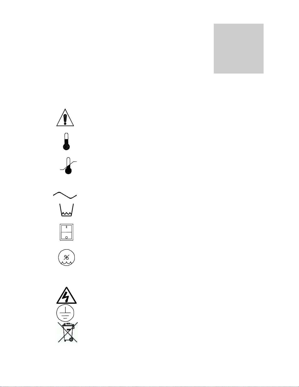
Your incubator has been provided with a display of graphic symbols which is designed to
help in identifying the use and function of the available user adjustable components.
2.1 Indicates that you should consult your manual for further description
or discussion of a control or user item.
2.2 Indicates "Temperature".
2.3 Indicates "Over-temperature safety".
2.4 C Indicates "Degrees Centigrade".
2.5 Indicates "AC power ON".
2.6 Indicates "Humidifier Water Low".
2.7 Indicates I/ON and O/OFF.
2.8 Indicates "Relative Humidity".
2.9 %RH Indicates "Percent Relative Humidity".
2.10 Indicates "Potential Shock Hazard" behind this protective partition.
2.11 Indicates "Protective Earth Ground".
2.12 Indicates “Unit should be recycled” (Not disposed of in land-fill)
Page 5

5
INSTALLATION
Section
Local city, county or other ordinances may govern the use of this equipment. If you have any
questions about local requirements, please contact the appropriate local agency. Installation may
be performed by the end user. It is unnecessary for this unit to be installed by a technician.
Under normal circumstances this unit is intended for use inside, at room temperatures between 5°C
and 40°C, at no greater than 75% relative humidity (at 25°C) and with a supply voltage that does
not vary by more than 10%. Customer Service should be contacted for operating conditions outside
of these limits.
3.1 Power Source: See the unit's serial data plate for voltage, cycle, wattage and ampere
requirements. If matched to your power source, plug the power cord into a grounded outlet.
VOLTAGE SHOULD NOT VARY MORE THAN 10% FROM THE SERIAL PLATE RATING.
These units are intended for 50/60 Hz application. A separate circuit is recommended to
preclude loss of product due to overloading or circuit failure. Note that electrical supply to
the unit must conform to all local and national electrical codes.
3.2 Location: In selecting a site, consider all conditions which may affect performance, such as
extreme heat from steam radiators, stoves, ovens, autoclaves, etc. Avoid direct sun, fast
moving air currents, heating/cooling ducts and high-traffic areas. To ensure air circulation
around the unit, allow a minimum of 5cm between the unit and any walls or partitions which
might obstruct free air flow.
Caution: Position and level the apparatus before connecting to water supply.
3.3 Lifting and Handling: These units are heavy and care should be taken to use appropriate
3.4 Leveling: The unit must sit level and solidly. Leveling feet (supplied) are to be installed at
3.5 Cleaning: The incubator was cleaned at the factory, but not sterilized. It should be
lifting devices that are sufficiently rated for these loads. Units should only be lifted from their
bottom surfaces. Doors, handles and knobs are not adequate for lifting or stabilization. The
unit should be completely restrained from tipping during lifting or transport. All moving parts,
such as shelves and trays should be removed and doors need to be positively locked in the
closed position during transfer to prevent shifting and damage.
the holes in the base of the unit. Turn them counterclockwise to raise level. If the unit must
be moved, turn the leveling feet in all the way to prevent damage.
disinfected prior to use. Remove all interior parts including shelves and shelf assembles.
Clean the chamber with a disinfectant that is appropriate to your application. Similar periodic
cleaning is strongly recommended. DO NOT USE chlorine-based bleaches or abrasives
as this will damage the stainless steel interior. DO NOT USE spray cleaners that might
leak through openings and cracks and get on electrical parts or that may contain solvents
that will harm the coatings. A similar periodic cleaning is recommended.
WARNING: Never clean the unit with alcohol or flammable cleaners with the unit connected
to the electrical supply. Always disconnect the unit form the electrical service when cleaning
Page 6

6
and assure all volatile or flammable cleaners are evaporated and dry before reattaching the
unit to the power supply.
3.6 Humidification Water Supply: On the back of the body there is a 1/4" compression fitting
marked WATER IN. This fitting should only be plumbed to a DISTILLED WATER supply
source. Please note that when attaching the water supply line to the fitting on the unit, two
wrenches must be used: one to hold the fitting from turning in the panel, while using the
other to tighten the compression fitting. The supply source should be gravity fed or
pressure can be regulated to no more than 2 psi with a water pressure regulator valve.
Deionized or tap water should NOT be used. They will have a detrimental effect on the
unit causing corrosion or obstructions and premature failure of this assembly, and
VOID your warranty.
3.7 Fill the Vapor Generator: It takes approximately 880cc (.88 Liter) to initially fill the vapor
generator, after that a continuous supply is required to maintain the operating level. If the
supply is disconnected or in some other manner cut off from the vapor generator, the level
will drop and the float switch in the vapor generator will shut the vapor generator off.
3.8 Water Drain Line: On the external back of the test chamber, at the bottom, there is a
copper drain line for excess condensation to drain from the bottom of the chamber. Ideally,
this line would be run into a floor drain, but could be run to a shallow pan with an automatic
sump pump. Under no circumstances should this line be plugged. If the line is plugged the
condensation will pool on the floor of the test chamber and flow out when the door is
opened.
3.9 Vapor Trap: Located in the water drain line, this must be filled with approximately ½ cup of
DISTILLED WATER. This will prevent the chamber humidity from escaping and still allow
any condensation to drain away. If the unit is not used for a long period of time this trap
should be flushed and refilled with distilled water.
3.10 Pressure Relief Valve: Marked RELIEF, this valve is located just to the right of the
WATER IN fitting at the back of the unit. It provides pressure relief for the vapor generator
system. The cracking pressure is 5. psi. The protective shipping cap must be removed
before operation as this valve should never be plugged or covered.
Page 7
7
CONTROL OVERVIEW
Section
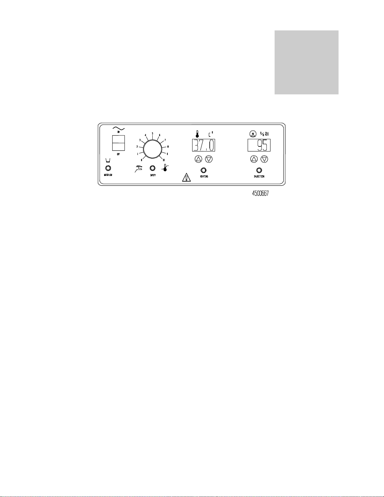
4.1 Power Switch: The main power I/O (On/Off) switch controls all power to the unit, and must be in the
I/On position before any systems are operational.
4.2 High Limit Safety Thermostat: This control is marked SAFETY and is adjacent to the power switch.
It is completely independent of the Main Temperature Controller and guards against any failure which
would allow the temperature to rise past set point. If the temperature rises to the safety set point, the
Safety takes control of the heating element and allows continued use of the unit until the problem can
be resolved or service can be arranged. Please note that it is not recommended that the unit be
allowed to operate using only the Safety Thermostat as temperature uniformity will suffer.
4.3 High Limit Indicator: This pilot light, located on the Main Control Panel just above the word
SAFETY, comes ON when the High Limit Safety Thermostat is activated. Under normal operating
conditions this pilot light should never come on.
4.4 Main Temperature Controller: This control is marked C and consists of the digital display and
UP/DOWN arrow pads for inputting set point temperatures and calibration.
4.5 Heating Indicator: This pilot light is marked HEATING and is on when the heating elements have
been activated to reach and maintain set point.
4.6 Relative Humidity Controller: This control is marked % RH, and consists of the digital display and
UP/DOWN arrow pads for inputting set point percents and calibration. The Relative Humidity
Controller maintains internal humidity through a direct set point of 1% increments and the digital
display indicates in 1% increments. This control is solid state and proportional. The controller utilizes a
solid state thin film capacitive humidity sensor to sense the humidity within the chamber.
4.7 Injection Indicator: This pilot light is marked INJECTION and is on when water vapor is being
injected into the chamber from the vapor generator.
4.8 Water Low Indicator: This pilot light is marked WATER LOW and is on when the water level drops
in the vapor generator. The float switch is tripped, the vapor generator is turned off, and water is
released from the supply. When the vapor generator becomes full, the float switch is tripped again,
the vapor generator is turned on, and the WATER LOW pilot light turns off.
4.9 Chart Recorder: Adjacent to the control panel is a cover plate that can be removed if a chart
recorder is to be installed. Chart recorders are available from your dealer. For further information see
Section 7.0, Chart Recorder Installation.
Page 8

8
THEORY OF OPERATION
Section
These humidity chambers are designed to maintain temperature and relative humidity at set
points controllable by the operator at the front panel. Air is constantly being circulated
through the chamber, monitored for comparison to set points and treated if necessary.
On all units, heating is done by electric resistance heaters that turn off and on for
temperature control. On the R units with cooling (SHC10R (HC9R), SHC10R -2 (HC9R-2),
SHC28R (HC30R), SHC28R-2 (HC30R-2)) the refrigeration compressor is continuously
active.
Chamber humidification is achieved by means of a low-pressure vapor generator injecting
water vapor into the chamber through a small orifice. The water vapor is introduced into the
chamber at the blower discharge.
It should be noted that even though the unit does incorporate an exhaust system to assist
in achieving humidity close to ambient, the unit has no way of achieving humidity lower than
that which the ambient environment will allow.
Page 9

9
OPERATION
Section
It is recommended that your unit be allowed to reach operating temperature before engaging the humidifying
system. This requires setting the RH set point to 0 (zero) until the unit is at operating temperature. See
Section 6.6 for changing the RH set point.
6.1 Turn the power switch to the I/ON position. Turn the High Limit Safety thermostat to its maximum
position, clockwise and place the shelves in the chamber.
6.2 Place a reference thermometer in the chamber where it can be easily viewed, and so that it is not
touching any shelves or chamber walls. Taping the thermometer to a petri dish is a method that works
well.
6.3 Set Main Temperature Control: To enter the set point on the control, push and release either the UP
or DOWN arrow pad one time and the digital display will start to blink from bright to dim. While
blinking, the display is showing the set point, which can be changed to the desired temperature by
pushing the UP or DOWN arrow pads. If the arrow pads are not pushed within five (5) seconds, the
display will stop blinking and will read the temperature in the chamber. Allow at least twenty- four (24)
hours for the temperature to stabilize. It is recommended that set point adjustments are made again
after the calibration procedure is completed.
6.4 Calibrating Temperature Control: Compare the reading on the reference thermometer with the
digital display. If there is an unacceptable difference, put the display into calibrate mode by pressing
both the UP and DOWN arrow pads at the same time and holding them in until the two outside
decimal points start to flash. When the decimal points are flashing, the display can be calibrated to
match the reference thermometer by pressing the UP or DOWN arrow pad until the display reads the
correct value. Allow the unit to stabilize again until five (5) consecutive readings at five (5) minute
intervals read a constant value.
6.5 Set the High Limit Safety Thermostat: After the Main Temperature Control is set and calibrated the
6.6 Set Humidity Control: First, place a reference hygrometer in the chamber where it can be easily
6.7 Calibrating Humidity Control: Compare the reading on the reference hygrometer with the digital
High Limit needs to be set. First turn the control knob counterclockwise just until the Safety Indicator
light comes on. Then slowly turn the knob clockwise just until the Safety Indicator light goes off. The
Safety thermostat should now be set approximately ten (10) degrees above the Main Temperature
Control set point.
viewed. To enter set point mode on the Humidity Control push and release either the UP or DOWN
arrow pad and the digital display will start to blink from bright to dim. While blinking, the display is
showing the set point which can be changed using the UP or DOWN arrow pads. If the arrow pads
are not pressed within five (5) seconds, the display will revert to showing the process or actual
parameter within the chamber. Allow at least twenty four (24) hours for the unit to stabilize.
CAUTION: When opening the door there is a danger from the steam/high humidity escaping.
The door should be opened a small amount (2" - 3") then paused until the steam cloud
dissipates.
display. If there is an unacceptable difference, put the display into calibrate mode by pressing both the
UP and DOWN arrow pads at the same time until the display begins to blink. When the display is
blinking it can be calibrated to match the reference hygrometer by using the Up/Down arrow pads until
it reads the correct value. If the arrow pads are not pressed within five (5) seconds, the display will
revert to showing the process or actual parameter within the chamber. Allow the unit to stabilize
again.
Page 10

10
CHART RECORDER INSTALLATION
Section
Please note that the following information is a general guide for installation. Before attempting
installation please read the instructions provided with your chart recorder thoroughly for specific
installation instructions.
NOTE: Unplug unit from the power supply before installing the Chart Recorder.
7.1 Remove cover for Chart Recorder, located on the right side of control panel.
7.2 Remove steel plate from the back of the Chart Recorder.
7.3 Open the front glass door on the Chart Recorder and loosen the two screws on the face of
the recorder. (Screws are on the top and bottom right of the face.)
7.4 Inside the unit, behind the cover plate, you will see two wires that say “Recorder Power”.
Cut off the butt connectors and strip the wires about 3/8 inch.
7.5 Put the Recorder Power wires through the hole in back of your Chart Recorder and connect
the Recorder Power wires to the terminal inside.
7.6 Run the Chart Recorder probe through the probe hole and slide into probe clips provided
inside the chamber of the unit.
7.7 Inside the Chart Recorder you will see a piece of masking tape and a metal clip; remove
these; screw face bolts back in; screw in the Chart Recorder; shut the glass door on the
Chart Recorder; plug unit into the power supply; then turn on your unit.
7.8 In removing or mounting a chart, the pen arm and stylus must be raised by pressing on the
7.9 To remove and replace a chart, unscrew the hub knob and swing it 90 clockwise, or to the
7.10 Now the pen arm may be gently released and the chart knob rotated counterclockwise back
tab at the uppermost end of the arm. Even if the recorder is not to be used, a fresh chart
should be mounted or some sort of padding placed under the stylus to protect the sapphire
tip.
3 o’clock position. Press the upper tab on the pen arm; lift the chart forward off the hub and
slide down and away. DO NOT release the pen arm, but install a new chart.
to the hub. Align the proper chart time with chart plate index.
Page 11

11
MAINTENANCE
Section
NOTE: Prior to any maintenance or service on this unit, disconnect power cord from
the power supply. Service of any electrical components should only be performed
by personnel who are qualified and familiar with the use and function of these
components.
8.1 Clean the chamber interior. Remove and clean shelves and shelf clips on a periodic
basis using a disinfectant that is suitable to your application. DO NOT USE
chlorine-based bleaches or abrasives as this will damage the stainless steel
interior. DO NOT USE spray cleaners that might leak through openings and cracks
and get on electrical parts or that may contain solvents that will harm the coatings. A
similar periodic cleaning is recommended.
WARNING: Never clean the unit with alcohol or flammable cleaners with the unit
connected to the electrical supply. Always disconnect the unit form the electrical
service when cleaning and assure all volatile or flammable cleaners are evaporated
and dry before reattaching the unit to the power supply.
8.2 When washing interior of unit, handle the gasket carefully, as not to impair the
positive seal. NOTE: DO NOT REMOVE TEFLON TAPE FROM DOOR, IT IS
THERE TO PREVENT THE DOOR FROM STICKING TO THE GASKET.
8.3 All electrical components are accessible from the top of the unit. Remove nuts
8.4 There is NO maintenance required on the Main Temperature Controller, Over
8.5 If the chamber fails to maintain temperature, review Section 8.0 before calling for
around edge of top and lift top off.
Temperature Safety, Main Temperature Probe, Humidity Control, or Humidity
Sensor.
service.
Page 12

12
TROUBLESHOOTING
TEMPERATURE
Temperature too high – display and
actual match
1/ controller set too high-see see section 6.3
2/ controller failed on – call Customer Service
3/ wiring error – call Customer Service
DISPLAY reads "HI" or "400"+
probe is unplugged, is broken or wire to sensor is broken – trace wire from display
to probe; move wire and watch display to see intermittent problems
Chamber temp goes way over set point
and then settles to set point
Recalibrate – see section 6.4
Temperature too low – display and actual
match
1/ high limit set too low – see section 6.5
2/ controller set too low – see section 6.3
3/ unit not recovered from door opening – wait for display to stop changing
4/ unit not recovered from power failure or being turned off – incubators will need
24 hours to warm up and stabilize
5/ element failure – see if heating light is on; compare current draw to data plate
6/ controller failure – confirm with front panel lights that controller is calling for heat
7/ high limit failure – confirm with front panel lights that Safety is operating correctly
8/ wiring problem – check all functions and compare wiring to owners manual especially around any areas recently worked on
9/ loose connection – check shadow box for loose connections
Display reads "LO"
1/ sensor is plugged in backwards – reverse sensor wires to controller
2/ if ambient temperature is lower than range of unit – compare set points and
ambient temperature to rated specifications in owners manual
Unit will not heat over some temperature
that is below set point
1/ confirm that fan is moving and that amperage and voltage match data plate –
check fan motor motion in shadow box and feel for air movement in chamber
2/ confirm that set point is set high enough –turn Safety Thermostat all the way
clockwise and see if heating light or safety light comes on
3/ check connections to sensor
4/ check calibration – using independent thermometer, follow instructions in section
6.4
Unit will not heat up at all
Section
Always make a visual inspection of the unit and control console when troubleshooting. Look for loose or
disconnected wires which may be the source of the trouble.
The incubator is designed so that no internal electrical servicing should be required under normal conditions. If
electrical servicing is necessary, it should be performed by qualified service personnel. For information on
where to reach technical service please see the manual cover. FOR PERSONAL SAFETY, ALWAYS
DISCONNECT THE POWER BEFORE SERVICING.
Page 13

13
1/ verify that controller is asking for heat by looking for Heating light – if pilot light is
not on continuously, there is a problem with the controller
2/ check amperage – amperage should be virtually at maximum rated (data plate)
amperage
3/ do all controller functions work?
4/ is the Safety Thermostat set high enough? – for diagnostics, should be turned
fully CCW with the pilot light never on
5/ has the fuse/circuit breaker blown?
Indicated chamber temperature unstable
1/ ±0.1 may be normal
2/ is fan working? – remove top panel and verify movement of cooling fan in center
of shadow box
3/ is ambient radically changing – either door opening or room airflow from heaters
or air conditioning ? – stabilize ambient conditions
4/ sensor miss-located, damaged or wires may be damaged - check mounts for
control and Safety Thermostat sensors, then trace wires or tubing between sensors
and controls
5/ calibration sensitivity – call Customer Service
6/ high limit set too low – be sure that Safety is more than 5 degrees over desired
set point; check if Safety pilot is on continuously; turn controller knob completely
clock-wise to see if problem solved then follow instructions in section 6.4
7/ electrical noise – remove nearby sources of RFI including motors, arcing relays
or radio transmitters
8/ bad connection on temperature sensor or faulty sensor – check connectors for
continuity and mechanical soundness while watching display for erratic behavior;
check sensor and wiring for mechanical damage
9/ bad connections or faulty solid state relay – check connectors for mechanical
soundness and look for corrosion around terminals or signs of arcing or other
visible deterioration
10/ Water jacket empty or low – check indicator warning light or water level at fill
port in back of unit.
Will not maintain set point
1/ assure that set point is at least 5 degrees over ambient
2/ see if ambient is fluctuating
Display and actual (from reference
thermometer) don’t match
1/ calibration error – see operator’s manual
2/ temperature sensor failure – evaluate if pilot light is operating correctly
3/ controller failure – evaluate if pilot light is operating correctly
4/ allow at least two hours to stabilize
5/ see if reference thermometer is certified
Reference thermometer does not match
digital display
See Temp-10
Can't adjust set points or calibration
1/ turn entire unit off and on to reset
2/ if repeatedly happens, call Customer Service
Calibrated at one temperature, but not at
another
This can be a normal condition when operating temperature varies widely, e.g.,
30C°. For maximum accuracy, calibration should be done at close to the set point
temperature.
HUMIDITY LEVEL
Can't achieve rated humidity/temp
1/ relative humidity sensor or controller failure
2/ check for bad door seal
3/ check for leaking water around steamer
4/ confirm a sufficient and distilled water source
5/ calibrate humidity sensor with independent reference
6/ assure that pressure relief valve is closed
7/ assure that steamer is working (see Humid-4)
8/ leaks in air intake flapper
Can’t decrease humidity to set point
Page 14

14
1/ assure that exhaust fan is working
2/ assure that exhaust fan blower casing is free of pooled water
3/ check solid state relay
4/ set point has to be 10 percentage points below reading on control to turn
exhaust fan on
5/ injection valve stuck open
6/ condensate drain tube plugged and pool of water in bottom of chamber
Can't adjust set points or calibration
1/ confirm all wire connections
2/ confirm software revision
3/ call Customer Service
Steam generator not working
1/ check if fill solenoid, injection valve, relief valve, float switch and relays are
working – see schematic in manual
2/ check for water leaks around steamer
3/ verify that relays are working
4/ verify that float switch is working
5/ confirm that heater is working
a- power to coil
b- is unit burned/shorted out
6/ pressure switch is working
7/ plumbing leak
Humidity unstable
1/ circulating fan failure
a- motor failure or no voltage to motor
b- fan not turning
c- ducts blocked
2/ relative humidity is lower than the unit can achieve at that operating
temperature
3/ chamber leaks
a- motor shaft seals
b- door seal
c- air intake flapper
REFRIGERATION
SHC10Rs (HC9Rs) & SHC28Rs (HC30Rs) ONLY
Temperature will not reach set point
1/ assure that power is going to heating coils
2/ if the displacement is erratic, see if air is being circulated
3/ confirm that controller is calling for heat (check front panel light)
4/ if light not coming on, check control set point and High Limit set point
5/ confirm that fan is operating and airflow is not blocked
6/ reset by turning unit off and on
Unit won't cool
If the compressor is running:
1/ see if condenser is cold but free of ice
2/ be sure that fan is circulating air in the chamber and over the compressor
3/ confirm proper sensor location and operation
4/ look for leaks in the chamber or around the door gasket
5/ assure ample room around the unit as described in manual –5cm minimum
6/ adjust calibration on controller
7/ compare ambient specifications to specs in the manual
8/ call customer service
If compressor isn’t running:
9/ check for non-operating solid state relay
10/ confirm that motor is operable
11/ check if motor has voltage to it
12/ see if refrigeration is running too hot and thermal cutoff activated:
a- dirty coil or poor circulation
b- coil next to heat source
c- ambient temperature too high
Making noise
1/ assure that fan is not miss-aligned
2/ Steady internal clicking may be broken spring or valve – call Customer
Service
MECHANICAL
Page 15

15
Door not sealing
1/ adjust hinge blocks or twist the door.
2/ Confirm that unit has not been damaged and body is not square.
Motor doesn't move
1/ if shaft spins freely: check connections to motor and check voltage to motor;
2/ if shaft rubs or is frozen, relieve binding and retest
Motor makes noise
1) Make sure that the fan or blower wheel is not contacting its housing. Adjust
the motor mounting bracket position to re-center the fan or blower wheel, if
necessary.
2) Check the fan or blower wheel for damage or out of balance condition.
Replace the fan or blower wheel if it is damaged or out of balance.
3) Turn the motor shaft to make sure that it spins freely. If it binds or the
bearings make a rubbing or scrapping sound then replace the motor.
Water leaking
1/ If leaking inside: dry chamber, run at temperature with door open. Check all
seams with flashlight including front face.
2/ If leaking outside: dry out and see if leak repeats and find source of leak.
Sources may include: fittings that need tightening, condensation due to missing
insulation or a leak developed in humidity generator.
OTHER
Controller on at all times - "locked-up"
1/ Adjust set point to room temperature. If the light goes out but is still heating,
replace the solid state relay.
2/ turn unit off and on to reset
3/ if cannot change any condition on the front panel, call Customer Service
Front panel displays are all off
1/ Check for wire damage.
Unit or wall fuse/circuit breaker is blown
1/ check wall power source
2/ compare current draw and compare to specs on data plate
3/ see what other loads are on the wall circuit
Unit will not turn on
1/ check wall power source
2/ check fuse/circuit breaker on unit or in wall
3/ see if unit is on, e.g., fan or heater, and just controller is off
4/ check all wiring connections, esp. around the on/off switch
Condensate appears on chamber walls of
humidity chamber
1/ Some condensation may be normal
2/ Minimize the movement of air around the unit and reduce the number of door
openings
Contamination in chamber
1/ see cleaning procedure in operator’s manual
2/ develop and follow SOP for specific application; include definition of cleaning
technique and maintenance schedule
Page 16

16
PARTS LISTS
DESCRIPTION
SHC10 (HC9)
115V
SHC10-2 (HC9-2)
220V
SHC10R (HC9R)
115V
SCH10R-2
(HC9R-2) 220V
Adjustable Feet
2700500
2700500
2700500
2700500
Blower Wheel, Aluminum
2600535
2600535
2600535
2600535
Blower Wheel, Plastic
2600544
2600544
2600544
2600544
Circuit Breaker
1100500
1100500
1100500
1100500
Element
2350563
2350554
2350562
2350554
Fan Blade
2600551
2600551
2600551
2600551
Fan Motor
4880564
4880563
4880564
4880563
Float Switch
7850563
7850563
7850563
7850563
Humidity Control
1750553
17560554
1750553
17560554
Humidity Sensor
4100504
4100504
4100504
4100504
Motor U.E.C.
4880512
4880512
4880572
4880512
ON/OFF Switch
7850570
7850570
7850570
7850570
Pilot Light, Green
4650554
4650554
4650554
4650554
Pilot Light, Red
4650553
4650553
4650553
4650553
Power Cord
1800516
1800537
1800516
1800537
Power Cord - European
NA
1800541
NA
1800541
Power Exhaust Assembly
9990559
9990562
9990559
9990562
Pressure Relief Valve
8600567
8600567
8600567
8600567
Pressure Switch
7850574
7850574
7850574
7850574
Refrigeration System
NA
NA
9990569
9990587
Relay
7030536
7030528
7030536
7030528
Shelf
5120525
5120525
5120525
5120525
Shelf Clip (4/Shelf)
1250512
1250512
1250512
1250512
Solenoid Valve
8600576
8600578
8600576
8600578
Temperature Controller
1750549
1750550
1750549
1750550
Thermostat, High Limit
1750861
1750861
1750861
1750861
Vapor Generator Assembly
9990663
9990664
9990663
9990664
Vapor Generator Element
2350520
2350521
2350520
2350521
Section
10
SHC10 and SHC10-2 (HC9 and HC9-2)
SHC10R and SHC10R-2 (HC9R and HC9R-2)
Page 17

17
SHC28 (HC30) and SHC28-2 (HC30R)
DESCRIPTION
SHC28 (HC30)
115V
SHC28-2 (HC30-2)
220V
SHC28R (HC30R)
115V
SHC28R-2 (HC30R-2)
220V
Blower Wheel, Aluminum
2600535
2600535
2600535
2600535
Blower Wheel, Plastic
2600544
2600544
2600544
2600544
Element, Main
2350563
2350554
2350563
2350554
Fan Blower Wheel
2600504
2600504
2600504
2600504
Fan Motor
4880564
4880563
4880564
4880563
Float Switch
7850563
7850563
7850563
7850563
Humidity Control
1750553
1750554
1750553
17560554
Humidity Sensor
4100504
4100504
4100504
4100504
Motor U.E.C.
4880504
4880504
4880504
4880504
ON/OFF Switch
7850570
7850570
7850570
7850570
Pilot Light, Green
4650554
4650554
4650554
4650554
Pilot Light, Red
4650553
4650553
4650553
4650553
Power Cord
1800529
1800537
1800517
1800537
Power Cord European
NA
1800541
NA
1800541
Power Exhaust Assembly
9990559
9990562
9990559
9990562
Power Relay
7030533
7030533
7030533
7030533
Pressure Relief Valve
8600567
8600567
8600567
8600567
Pressure Switch
7850574
7850574
7850574
7850574
Refrigeration System
NA
NA
9990570
9990588
Relay
7030536
7030528
7030536
7030528
Shelf
9750531
9750531
9750531
9750531
Shelf Clip (4/Shelf)
1250512
1250512
1250512
1250512
Solenoid Valve
8600576
8600578
8600576
8600578
Temperature Controller
1750549
1750550
1750549
1750550
Thermostat, RS
1750861
1750861
1750861
1750861
Vapor Generator Assy.
9990643
9990644
9990643
9990644
Vapor Generator Element
2350520
2350520
2350520
2350520
SHC28R (HC30R) and SHC28R-2 (HC30R-2)
Page 18

18
UNIT SPECIFICATIONS
Weight
Shipping
Net
SHC10 SHC10-2
(HC9 HC9-2)
480 lbs.
341 lbs.
SHC10R SHC10R-2
(HC9R HC9R-2)
515 lbs.
401 lbs.
SHC28 SHC28-2
(HC30 HC30-2)
630 lbs.
460 lbs.
SHC28R SHC28R-2
(HC30R HCR30-2)
670 lbs.
460 lbs.
Dimensions
Exterior WxDxH (in.)
Interior WxDxH (in.)
SHC10 SHC10-2
(HC9 HC9-2)
44 x 32.75 x 57
28 x 20.25 x 26
SHC10R SHC10R-2
(HC9R HC9R-2)
44 x 32.75 x 57
28 x 20.25 x 26
SHC28 SHC28-2
(HC30 HC30-2)
42.5 x 37 x 85
30.25 x 26 x 62
SHC28R SHC28R-2
(HC30R HCR30-2)
42.5 x 37 x 85
30.25 x 26 x 62
Capacity
Cubic Feet
SHC10 SHC10-2
(HC9 HC9-2)
8.5
SHC10R SHC10R-2
(HC9R HC9R-2)
8.5
SHC28 SHC28-2
(HC30 HC30-2)
28
SHC28R SHC28R-2
(HC30R HCR30-2)
28
Temperature
Range
Humidity
SHC10 SHC10-2
(HC9 HC9-2)
40 to 70
40-95%
SHC10R SHC10R-2
(HC9R HC9R-2)
10 to 70
40-95%
SHC28 SHC28-2
(HC30 HC30-2)
40 to 70
40-95%
SHC28R SHC28R-2
(HC30R HCR30-2)
10 to 70
40-95%
Page 19

RELATIVE HUMIDITY CHART
Page 20

2
1 2
4
FAN
1 2
4
12VDC
POWER SUPPLY
6750507
OUT
IN
RH SENSOR
4100504
1 2
3
4
FAN
BM
BLUE
WHITE
RED
BLACK
BLOWER
MOTOR
4880504
GREEN LIGHTED SWITCH 7850570
WATER LOW
INDICATOR
4650553
STEAMER RELAY
7030536
HEATER REDUCTION
RELAY
7030536
220° LIMIT
1750615
PRESSURE SWITCH
7850574
FLOAT SWITCH
7850563
WATER FILL
SOLENOID
8600576
STEAMER HEATER
2350524
600V 6A
DIODE
2050500
QUENCHARK 7830507
CONDENSING UNIT
7010521
TEMPERATURE
CONTROL
1750549
OTL LIGHT
4650553
75°C LIMIT
1750860
CHILLER TANK HEATER
17.8Ω 120V 800W
CHAMBER HEATER
57Ω 120V 250W
HEAT LIGHT
4650554
OTL CONTROL
1750861
45°C COMPRESSOR
CUT OFF
1750862
RH CONTROL
1750553
SOLID
STATE RELAY
7030533
HUMIDIYT EXHAUST
FAN
4880564
HUMIDITY
INJECTION SOLENOID
8600576
HUMIDITY LIGHT
4650554
13 14
13 14
5
1
9
9
1
5
BLACK
BLACK
BLACK
BLACK
BLACK
BLACK
BLACK
WHITE
WHITE
WHITE
WHITE
WHITE
WHITE
WHITE
BLACK
CP
CHART RECORDER
CIRCULATING PUMP
6700563
BLACK
BLACK
WHITE WHITE
TERMINAL BLOCK 5 THROUGH 8
TERMINAL BLOCK 1 THROUGH 4
P2
P3
P13
P8
P20
P5
P12
P7
P11
P18
P21
P14
P17
P24
P19
P1 P14
P20
P19
P24
P17
P2
P15
P13
P8
P3
P21
P18
P11
P16
P22
P12
P5
P9
P7
P4
P1
ORANGE
CURCUIT BREAKER
1100500
POWER CORD
1800517
BLACK
BLACK 18G
BLACK
BLACK
YELLOW
YELLOW
WHITE
RED RED RED
WHITE
WHITE
RED HT
WHITE HT
BLUE
BLUE
BLACK
BROWN
WHITE
RED
RED
BLACK HT
BLACK HT
BLACK HT
WHITE HT
WHITE HT
WHITE
WHITE
WHITE
WHITE
WHITE
WHITE
WHITE 18G
RED 22G
BLACK 22G
P10
WIRING DIAGRAM
SHC10 (HC9)
(9851449)
Page 21
3
1 2
4
12VDC
POWER SUPPLY
6750507
OUT
IN
RH SENSOR
4100504
1 2
3
4
FAN
BM
BLUE
WHITE
RED
BLACK
BLOWER
MOTOR
4880504
GREEN LIGHTED SWITCH 7850570
WATER LOW
INDICATOR
4650553
STEAMER RELAY
7030528
220° LIMIT
1750615
PRESSURE SWITCH
7850574
FLOAT SWITCH
7850563
WATER FILL
SOLENOID
8600578
STEAMER HEATER
2350533
QUENCHARK 7830507
TEMPERATURE
CONTROL
1750550
OTL LIGHT
4650553
CHAMBER HEATER
250V 750W
2350554
HEAT LIGHT
4650554
OTL CONTROL
1750861
RH CONTROL
1750554
SOLID
STATE RELAY
7030533
HUMIDIYT EXHAUST
FAN
4880564
HUMIDITY
INJECTION SOLENOID
8600578
HUMIDITY LIGHT
4650554
BLACK
BLACK
BLACK
BLACK
BLACK
BLACK
WHITE
WHITE
WHITE
WHITE
WHITE
WHITE
BLACK
CHART RECORDER
BLACK
BLACK
WHITE WHITE
TERMINAL BLOCK 5 THROUGH 8
TERMINAL BLOCK 1 THROUGH 4
P2
P3
P13
P8
P20
P5
P12
P7
P11
P18
P14
P17
P24
P1 P14
P19
P24
P17
P2
P13
P8
P3
P18
P11
P16
P22
P12
P5
P9
P7
P4
P1
ORANGE
P10
2800503
EMI
FILTER
POWER
FUSED
INLET
4200505
WHITE WHITE
5
3
1
7 8
BLACK
WHITE
YELLOW
YELLOW
BLACK 18G
WHITE WHITE
RED
RED
BLACK HT
BLUE
BLUE
WHITE
RED
RED
RED HT
BLACK WHITE
WHITE HT
WHITE
WHITE
WHITE
WHITE
WHITE HT
WHITE 18G
BROWN
RED 22G
BLACK 22G
WIRING DIAGRAM
SHC10-2 (HC9-2)
(9851450)
Page 22

4
1 2
4
FAN
1 2
4
12VDC
POWER SUPPLY
6750507
OUT
IN
RH SENSOR
4100504
1 2
3
4
FAN
BM
BLUE
WHITE
RED
BLACK
BLOWER
MOTOR
4880504
GREEN LIGHTED SWITCH 7850570
WATER LOW
INDICATOR
4650553
STEAMER RELAY
7030536
220° LIMIT
1750615
PRESSURE SWITCH
7850574
FLOAT SWITCH
7850563
WATER FILL
SOLENOID
8600576
STEAMER HEATER
2350532
QUENCHARK 7830507
CONDENSING UNIT
7010521
TEMPERATURE
CONTROL
1750549
OTL LIGHT
4650553
75°C LIMIT
1750860
CHILLER TANK HEATER
17.8Ω 120V 800W
CHAMBER HEATER
57Ω 120V 250W
HEAT LIGHT
4650554
OTL CONTROL
1750861
45°C COMPRESSOR
CUT OFF
1750862
RH CONTROL
1750553
SOLID
STATE RELAY
7030533
HUMIDIYT EXHAUST
FAN
4880564
HUMIDITY
INJECTION SOLENOID
8600576
HUMIDITY LIGHT
4650554
13 14
9
1
5
BLACK
BLACK
BLACK
BLACK
BLACK
BLACK
BLACK
WHITE
WHITE
WHITE
WHITE
WHITE
WHITE
WHITE
BLACK
CP
CHART RECORDER
CIRCULATING PUMP
6700563
BLACK
BLACK
WHITE WHITE
TERMINAL BLOCK 5 THROUGH 8
TERMINAL BLOCK 1 THROUGH 4
P2
P3
P13
P8
P20
P5
P12
P7
P11
P18
P21
P14
P17
P24
P19
P1 P14
P20
P19
P24
P17
P2
P15
P13
P8
P3
P21
P18
P11
P16
P22
P12
P5
P9
P7
P4
P1
ORANGE
CURCUIT BREAKER
1100500
POWER CORD
1800517
BLACK
BLACK 18G
BLACK
BLACK
YELLOW
YELLOW
WHITE
RED RED
WHITE
WHITE
RED HT
WHITE HT
BLUE
BLUE
BROWN
WHITE
RED
RED
BLACK HT
BLACK HT
BLACK HT
WHITE HT
WHITE HT
WHITE
WHITE
WHITE
WHITE
WHITE
WHITE
WHITE 18G
RED 22G
BLACK 22G
P10
WIRING DIAGRAM
SHC10R (HC9R)
(9851451)
Page 23

5
WIRING DIAGRAM
2800503
EMI
FILTER
1 2
4
FAN
1 2
4
12VDC
POWER SUPPLY
6750507
OUT
IN
RH SENSOR
4100504
1 2
3
4
FAN
BM
BLUE
WHITE
RED
BLACK
BLOWER
MOTOR
4880504
POWER FUSED
INLET
4200505
GREEN LIGHTED SWITCH 7850570
WATER LOW
INDICATOR
4650553
STEAMER RELAY
7030528
220° LIMIT
1750615
PRESSURE SWITCH
7850574
FLOAT SWITCH
7850563
WATER FILL
SOLENOID
8600578
STEAMER HEATER
2350533
QUENCHARK 7830507
CONDENSING UNIT
7010543
TEMPERATURE
CONTROL
1750550
OTL LIGHT
4650553
75°C LIMIT
1750860
CHILLER TANK HEATER
67Ω 240V 800W
CHAMBER HEATER
201Ω 240V 250W
HEAT LIGHT
4650554
OTL CONTROL
1750861
45°C COMPRESSOR
CUT OFF
1750862
RH CONTROL
1750554
SOLID
STATE RELAY
7030533
HUMIDIYT EXHAUST
FAN
4880563
HUMIDITY
INJECTION SOLENOID
8600578
HUMIDITY LIGHT
4650554
7 8
5
1
3
BLACK
BLACK
BLACK
BLACK
BLACK
BLACK
BLACK
BLACK
WHITE WHITE
WHITE
WHITE
WHITE
WHITE
WHITE
WHITE
WHITE
BLACK
CP
CHART RECORDER
CIRCULATING PUMP
6700564
BLACK
BLACK
WHITE WHITE
TERMINAL BLOCK 5 THROUGH 8
TERMINAL BLOCK 1 THROUGH 4
P2
P3
P13
P8
P20
P5
P12
P7
P11
P18
P21
P14
P17
P24
P19
P1 P14
P20
P19
P24
P17
P2
P15
P13
P8
P3
P21
P18
P11
P16
P22
P12
P5
P9
P7
P4
P1
ORANGE
BLACK 18G
YELLOW
YELLOW
RED
RED
BLACK
BLACK
BLUE
BLUE
BROWN
BLACK HT
BLACK HT
BLACK HT
WHITE
WHITE
WHITE HT
WHITE
WHITE
RED RED
RED HT
WHITE HT
WHITE
WHITE
WHITE
RED 22G
BLACK 22G
WHITE
WHITE
BROWN
WHITE HT
WHITE
WHITE
SHC10R-2 (HC9R-2)
(9851452)
Page 24

6
WIRING DIAGRAM
1 2
4
12VDC
POWER SUPPLY
6750507
OUT
IN
RH SENSOR
4100504
1 2
3
4
FAN
BM
BLUE
WHITE
RED BLACK
BLOWER
MOTOR
4880504
GREEN LIGHTED SWITCH 7850570
WATER LOW
INDICATOR
4650553
STEAMER RELAY
7030536
220° LIMIT
1750615
PRESSURE SWITCH
7850574
FLOAT SWITCH
7850563
WATER FILL
SOLENOID
8600576
STEAMER HEATER
2350524
QUENCHARK 7830507
TEMPERATURE
CONTROL
1750549
OTL LIGHT
4650553
CHAMBER HEATER
120V 750W
2350563
HEAT LIGHT
4650554
OTL CONTROL
1750861
RH CONTROL
1750553
SOLID
STATE RELAY
7030533
HUMIDIYT EXHAUST
FAN
4880564
HUMIDITY
INJECTION SOLENOID
8600576
HUMIDITY LIGHT
4650554
13 14
BLACK
BLACK
BLACK
BLACK
BLACK
BLACK
WHITE
WHITE
WHITE
WHITE
WHITE
WHITE
BLACK
CHART RECORDER
BLACK
BLACK
WHITE WHITE
POWER CORD
1800529
CIRCUIT BREAKER
1100500
9
1
5
TERMINAL BLOCK 5 THROUGH 8
TERMINAL BLOCK 1 THROUGH 4
P2
P3
P13
P8
P20
P5
P12
P7
P11
P18
P14
P17
P24
P1 P14
P19
P24
P17
P2
P13
P8
P3
P18
P11
P16
P22
P12
P5
P9
P7
P4
P1
ORANGE
P10
WHITE
YELLOW
YELLOW
BLACK 18G
RED RED RED HT
BLUE
BLUE
WHITE
RED
RED
BLACK HT
BLACK
WHITE
WHITE HT
WHITE
WHITE
WHITE
WHITE
WHITEWHITE
WHITE HT
WHITE 18G
RED 22G
BLACK 22G
BROWN
SHC28 (HC30)
(9851453)
Page 25

7
1 2
4
12VDC
POWER SUPPLY
6750507
OUT
IN
RH SENSOR
4100504
1 2
3
4
FAN
BM
BLUE
WHITE
RED
BLACK
BLOWER
MOTOR
4880504
GREEN LIGHTED SWITCH 7850570
WATER LOW
INDICATOR
4650553
STEAMER RELAY
7030528
220° LIMIT
1750615
PRESSURE SWITCH
7850574
FLOAT SWITCH
7850563
WATER FILL
SOLENOID
8600578
STEAMER HEATER
2350525
QUENCHARK 7830507
TEMPERATURE
CONTROL
1750550
OTL LIGHT
4650553
CHAMBER HEATER
250V 750W
2350554
HEAT LIGHT
4650554
OTL CONTROL
1750861
RH CONTROL
1750554
SOLID
STATE RELAY
7030533
HUMIDIYT EXHAUST
FAN
4880564
HUMIDITY
INJECTION SOLENOID
8600578
HUMIDITY LIGHT
4650554
BLACK
BLACK
BLACK
BLACK
BLACK
BLACK
WHITE
WHITE
WHITE
WHITE
WHITE
WHITE
BLACK
CHART RECORDER
BLACK
BLACK
WHITE WHITE
TERMINAL BLOCK 5 THROUGH 8
TERMINAL BLOCK 1 THROUGH 4
P2
P3
P13
P8
P20
P5
P12
P7
P11
P18
P14
P17
P24
P1 P14
P19
P24
P17
P2
P13
P8
P3
P18
P11
P16
P22
P12
P5
P9
P7
P4
P1
ORANGE
P10
2800503
EMI
FILTER
POWER
FUSED
INLET
4200505
WHITE WHITE
5
3
1
7 8
BLACK
WHITE
YELLOW
YELLOW
BLACK 18G
WHITE WHITE
RED
RED
BLACK HT
BLUE
BLUE
WHITE
RED
RED
RED HT
BLACK WHITE
WHITE HT
WHITE
WHITE
WHITE
WHITE
WHITE HT
WHITE 18G
BROWN
RED 22G
BLACK 22G
WIRING DIAGRAM
SHC28-2 (HC30-2)
(9851454)
Page 26

8
1 2
4
FAN
1 2
4
12VDC
POWER SUPPLY
6750507
OUT
IN
RH SENSOR
4100504
1 2
3
4
FAN
BM
BLUE
WHITE
RED
BLACK
BLOWER
MOTOR
4880504
GREEN LIGHTED SWITCH 7850570
WATER LOW
INDICATOR
4650553
STEAMER RELAY
7030536
HEATER REDUCTION
RELAY
7030536
220° LIMIT
1750615
PRESSURE SWITCH
7850574
FLOAT SWITCH
7850563
WATER FILL
SOLENOID
8600576
STEAMER HEATER
2350524
600V 6A
DIODE
2050500
QUENCHARK 7830507
CONDENSING UNIT
7010521
TEMPERATURE
CONTROL
1750549
OTL LIGHT
4650553
75°C LIMIT
1750860
CHILLER TANK HEATER
17.8Ω 120V 800W
CHAMBER HEATER
57Ω 120V 250W
HEAT LIGHT
4650554
OTL CONTROL
1750861
45°C COMPRESSOR
CUT OFF
1750862
RH CONTROL
1750553
SOLID
STATE RELAY
7030533
HUMIDIYT EXHAUST
FAN
4880564
HUMIDITY
INJECTION SOLENOID
8600576
HUMIDITY LIGHT
4650554
13 14
13 14
5
1
9
9
1
5
BLACK
BLACK
BLACK
BLACK
BLACK
BLACK
BLACK
WHITE
WHITE
WHITE
WHITE
WHITE
WHITE
WHITE
BLACK
CP
CHART RECORDER
CIRCULATING PUMP
6700563
BLACK
BLACK
WHITE WHITE
TERMINAL BLOCK 5 THROUGH 8
TERMINAL BLOCK 1 THROUGH 4
P2
P3
P13
P8
P20
P5
P12
P7
P11
P18
P21
P14
P17
P24
P19
P1 P14
P20
P19
P24
P17
P2
P15
P13
P8
P3
P21
P18
P11
P16
P22
P12
P5
P9
P7
P4
P1
ORANGE
CURCUIT BREAKER
1100500
POWER CORD
1800517
BLACK
BLACK 18G
BLACK
BLACK
YELLOW
YELLOW
WHITE
RED RED RED
WHITE
WHITE
RED HT
WHITE HT
BLUE
BLUE
BLACK
BROWN
WHITE
RED
RED
BLACK HT
BLACK HT
BLACK HT
WHITE HT
WHITE HT
WHITE
WHITE
WHITE
WHITE
WHITE
WHITE
WHITE 18G
RED 22G
BLACK 22G
P10
WIRING DIAGRAM
SHC28R (HC30R)
(9851455)
Page 27

9
WIRING DIAGRAM
2800503
EMI
FILTER
1 2
4
FAN
1 2
4
12VDC
POWER SUPPLY
6750507
OUT
IN
RH SENSOR
4100504
1 2
3
4
FAN
BM
BLUE
WHITE
RED
BLACK
BLOWER
MOTOR
4880504
POWER FUSED
INLET
4200505
GREEN LIGHTED SWITCH 7850570
WATER LOW
INDICATOR
4650553
STEAMER RELAY
7030528
HEATER REDUCTION
RELAY
7030528
220° LIMIT
1750615
PRESSURE SWITCH
7850574
FLOAT SWITCH
7850563
WATER FILL
SOLENOID
8600578
STEAMER HEATER
2350525
600V 6A
DIODE
2050500
QUENCHARK 7830507
CONDENSING UNIT
7010543
TEMPERATURE
CONTROL
1750550
OTL LIGHT
4650553
75°C LIMIT
1750860
CHILLER TANK HEATER
67Ω 240V 800W
CHAMBER HEATER
201Ω 240V 250W
HEAT LIGHT
4650554
OTL CONTROL
1750861
45°C COMPRESSOR
CUT OFF
1750862
RH CONTROL
1750554
SOLID
STATE RELAY
7030533
HUMIDIYT EXHAUST
FAN
4880563
HUMIDITY
INJECTION SOLENOID
8600578
HUMIDITY LIGHT
4650554
7 8
7
8
1
3
5
5
1
3
BLACK
BLACK
BLACK
BLACK
BLACK
BLACK
BLACK
BLACK
WHITE WHITE
WHITE
WHITE
WHITE
WHITE
WHITE
WHITE
WHITE
BLACK
CP
CHART RECORDER
CIRCULATING PUMP
6700564
BLACK
BLACK
WHITE WHITE
TERMINAL BLOCK 5 THROUGH 8
TERMINAL BLOCK 1 THROUGH 4
P2
P3
P13
P8
P20
P5
P12
P7
P11
P18
P21
P14
P17
P24
P19
P1 P14
P20
P19
P24
P17
P2
P15
P13
P8
P3
P21
P18
P11
P16
P22
P12
P5
P9
P7
P4
P1
ORANGE
BLACK 18G
YELLOW
YELLOW
RED
RED
BLACK
BLACK
BLUE
BLUE
BROWN
BLACK HT
BLACK HT
BLACK HT
WHITE
WHITE
WHITE HT
WHITE
WHITE
RED RED RED
RED HT
WHITE HT
WHITE
WHITE
WHITE
WHITE
RED 22G
BLACK 22G
WHITE
WHITE
BLACK
BROWN
WHITE HT
WHITE
WHITE
SHC28R-2 (HC30R-2)
(9851456)
 Loading...