

Page 1
GRAVITY OVENS 110 – 120 Voltage
Installation - Operation Manual
SGO1 SGO3 SGO5
Page 2

2 | Page
Page 3
SGO Gravity Ovens 110 – 120 Voltage
Part Number (Manual): 4861727
Revision: March 30, 2018
Pictured on Cover: Left to right SGO1, SGO3, SGO5
SLG122, SLG322, SLG522
SHEL LAB is a brand of Sheldon Manufacturing, INC.
Safety Certifications
These units are CUE listed by TÜV SÜD as gravity ovens for professional, industrial, or educational
use where the preparation or testing of materials is done at an ambient air pressure range of 22.14 –
31.3 inHg (75 – 106 kPa) and no flammable, volatile, or combustible materials are being heated.
The units have been tested to the following requirements:
CAN/CSA-22.2 No. 61010-1:2012/U2:2016-04
CAN/CSA-C22.2 No. 61010-2-010:2015
UL 61010-1:2012/R:2016-04
UL 61010-2-010:2015
EN 61010-1:2010
EN 61010-2-010:2014
3 | Page
Page 4

TABLE OF CONTENTS
INTRODUCTION ........................................................................................................................................................ 5
Read this Manual .................................................................................................................................................................... 5
Safety Considerations and Requirements ...................................................................................................................... 5
Contacting Assistance .......................................................................................................................................................... 6
Engineering Improvements.................................................................................................................................................. 6
Reference Sensor Device .................................................................................................................................................... 7
RECEIVING YOUR UNIT ........................................................................................................................................... 9
Inspect the Shipment ............................................................................................................................................................. 9
Orientation Photos ............................................................................................................................................................... 10
Recording Data Plate Information ................................................................................................................................... 14
INSTALLATION ......................................................................................................................................................... 15
Installation Procedure Checklist ...................................................................................................................................... 15
Required Ambient Conditions ........................................................................................................................................... 16
Required Ventilation Clearances ..................................................................................................................................... 16
Power Source Requirements ............................................................................................................................................. 17
Lifting and Handling ............................................................................................................................................................ 18
Leveling ................................................................................................................................................................................... 18
Install the Oven ..................................................................................................................................................................... 19
Deionized and Distilled Water .......................................................................................................................................... 19
Installation - Clean and Disinfect ..................................................................................................................................... 19
Shelving Installation............................................................................................................................................................ 20
Access Port Stopper ........................................................................................................................................................... 20
GRAPHIC SYMBOLS ................................................................................................................................................ 21
CONTROL PANEL OVERVIEW .............................................................................................................................. 23
OPERATION.............................................................................................................................................................. 25
Operating Precautions ....................................................................................................................................................... 25
Theory of Operation ........................................................................................................................................................... 26
Put the Oven into Operation ............................................................................................................................................ 28
Set the Temperature Set Point ........................................................................................................................................ 29
Set the Over Temperature Limit ...................................................................................................................................... 30
Setting the Timer .................................................................................................................................................................. 31
Launching a Heating Profile ............................................................................................................................................. 33
High Exterior Temperatures ............................................................................................................................................. 34
Drying Racks and other Accessories ............................................................................................................................. 34
USER MAINTENANCE ............................................................................................................................................. 35
Cleaning and Disinfecting ................................................................................................................................................. 35
Gaskets and Chamber Integrity ...................................................................................................................................... 36
Electrical Components ....................................................................................................................................................... 36
Calibrate the Temperature Display ................................................................................................................................. 37
UNIT SPECIFICATIONS ........................................................................................................................................... 41
Weight ...................................................................................................................................................................................... 41
Dimensions ............................................................................................................................................................................. 41
Capacity .................................................................................................................................................................................. 41
Shelf Capacity by Weight .................................................................................................................................................. 42
Temperature ......................................................................................................................................................................... 42
Power ...................................................................................................................................................................................... 43
PARTS LIST ............................................................................................................................................................... 45
4 | Page
Page 5

INTRODUCTION
Thank you for purchasing a SHEL LAB oven. We know you have many choices in today’s competitive
marketplace when it comes to constant temperature equipment. We appreciate you choosing ours. We
stand behind our products and will be here if you need us.
READ THIS MANUAL
Failure to follow the guidelines and instructions in this user manual may create a protection
impairment by disabling or interfering with the unit safety features. This can result in injury or death.
Before using the unit, read the manual in its entirety to understand how to install, operate, and
maintain the unit in a safe manner. Keep this manual available for use by all operators. Ensure all
operators are given appropriate training before the unit begins service.
SAFETY CONSIDERATIONS AND REQUIREMENTS
Follow basic safety precautions, including all national laws, regulations, and local ordinances in your
area regarding the use of this unit. If you have any questions about local requirements, please
contact the appropriate agencies.
SOPs
Because of the range of potential applications this unit can be used for, the operator or their
supervisors must draw up a site-specific standard operating procedure (SOP) covering each
application and associated safety guidelines. This SOP must be written and available to all operators
in a language they understand.
Intended Applications and Locations
SGO gravity ovens are engineered for constant temperature drying, curing, and baking applications
in professional, industrial, and educational environments. The ovens are not intended for use at
hazardous or household locations.
Power
Your unit and its recommended accessories are designed and tested to meet strict safety
requirements.
• The unit is designed to connect to a power source using the specific power cord type
shipped with the unit.
• Always plug the unit power cord into a protective earth grounded electrical outlet
conforming to national and local electrical codes. If the unit is not grounded properly, parts
such as knobs and controls can conduct electricity and cause serious injury.
• Do not bend the power cord excessively, step on it, or place heavy objects on it.
• A damaged cord can be a shock or fire hazard. Never use a power cord if it is damaged or
altered in any way.
• Use only approved accessories. Do not modify system components. Any alterations or
modifications to your unit not explicitly authorized by the manufacturer can be dangerous
and will void your warranty.
5 | Page
Page 6

INTRODUCTION
CONTACTING ASSISTANCE
Phone hours for Sheldon Technical Support are 6 am – 4:30 pm Pacific Coast Time (west coast of
the United States, UTC -8), Monday through Friday. Please have the following information ready
when calling or emailing Technical Support: the model number and the serial number (see page 14).
EMAIL: support@sheldonmfg.com
PHONE: 1-800-322-4897 extension 4, or (503) 640-3000
FAX: (503) 640-1366
Sheldon Manufacturing, INC.
P.O. Box 627
Cornelius, OR 97113
ENGINEERING IMPROVEMENTS
Sheldon Manufacturing, Inc. continually improves all of its products. As a result, engineering changes
and improvements are made from time to time. Therefore, some changes, modifications, and
improvements may not be covered in this manual. If your unit’s operating characteristics or
appearance differs from those described in this manual, please contact your SHEL LAB dealer or
customer service representative for assistance.
6 | Page
Page 7
Temperature
INTRODUCTION
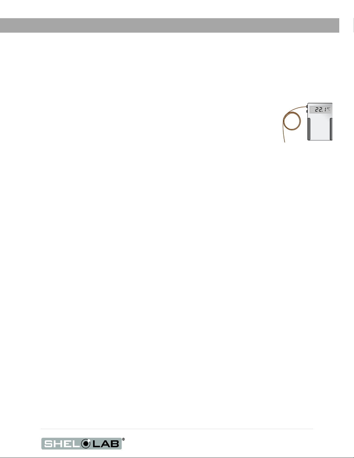
REFERENCE SENSOR DEVICE
Must be purchased separately
A reference sensor device is required for calibrating the unit temperature display.
Reference devices must meet the following standards:
• Accurate to at least 1°C
The device should be regularly calibrated, preferably by a third party.
Temperature Probes
Use a digital device with wire thermocouple probes that can be introduced into the oven chamber
through the unit access port. Select thermocouples suitable for the application temperature you will be
calibrating at.
Why Probes?
Reference readings taken outside the chamber using wire temperature probes avoid chamber door
openings. Openings disrupt the chamber temperature. Each disruption requires a minimum 1-hour wait
to allow the atmosphere to re-stabilize before continuing.
No Alcohol or Mercury Thermometers
Alcohol thermometers do not have sufficient accuracy to conduct accurate temperature calibrations.
Never place a mercury thermometer in the unit chamber. Always use thermocouple probes.
Reference
7 | Page
Page 8

INTRODUCTION
8 | Page
Page 9
RECEIVING YOUR UNIT
INSPECT THE SHIPMENT
• When a unit leaves the factory, safe delivery becomes the responsibility of the carrier.
• Damage sustained during transit is not covered by the manufacturing defect warranty.
• Save the shipping carton until you are certain the unit and its accessories function properly.
When you receive your unit, inspect it for concealed loss or damage to its interior and exterior. If you
find any damage to the unit, follow the carrier’s procedure for claiming damage or loss.
1. Carefully inspect the shipping carton for damage.
2. Report any damage to the carrier service that delivered the unit.
3. If the carton is not damaged, open the carton and remove the contents.
4. Inspect the unit for signs of damage. See the orientation depiction on the next page as a
reference.
5. The unit should come with an Installation and Operation Manual.
6. Verify that the correct number of accessory items has been included.
7. A high-temperature access port stopper ships installed in the port located on the back of the
oven. Verify the presence of the stopper.
8. Carefully check all packaging for accessory items before discarding.
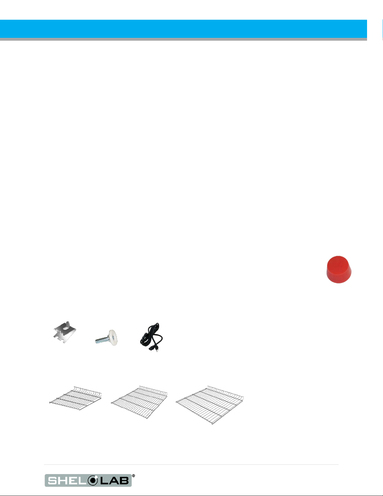
Included Accessories
4 Leveling
Feet
1 Power Cord
8 Shelf Clips
Shelves
SGO1 SGO3 SGO5
9 | Page
Page 10
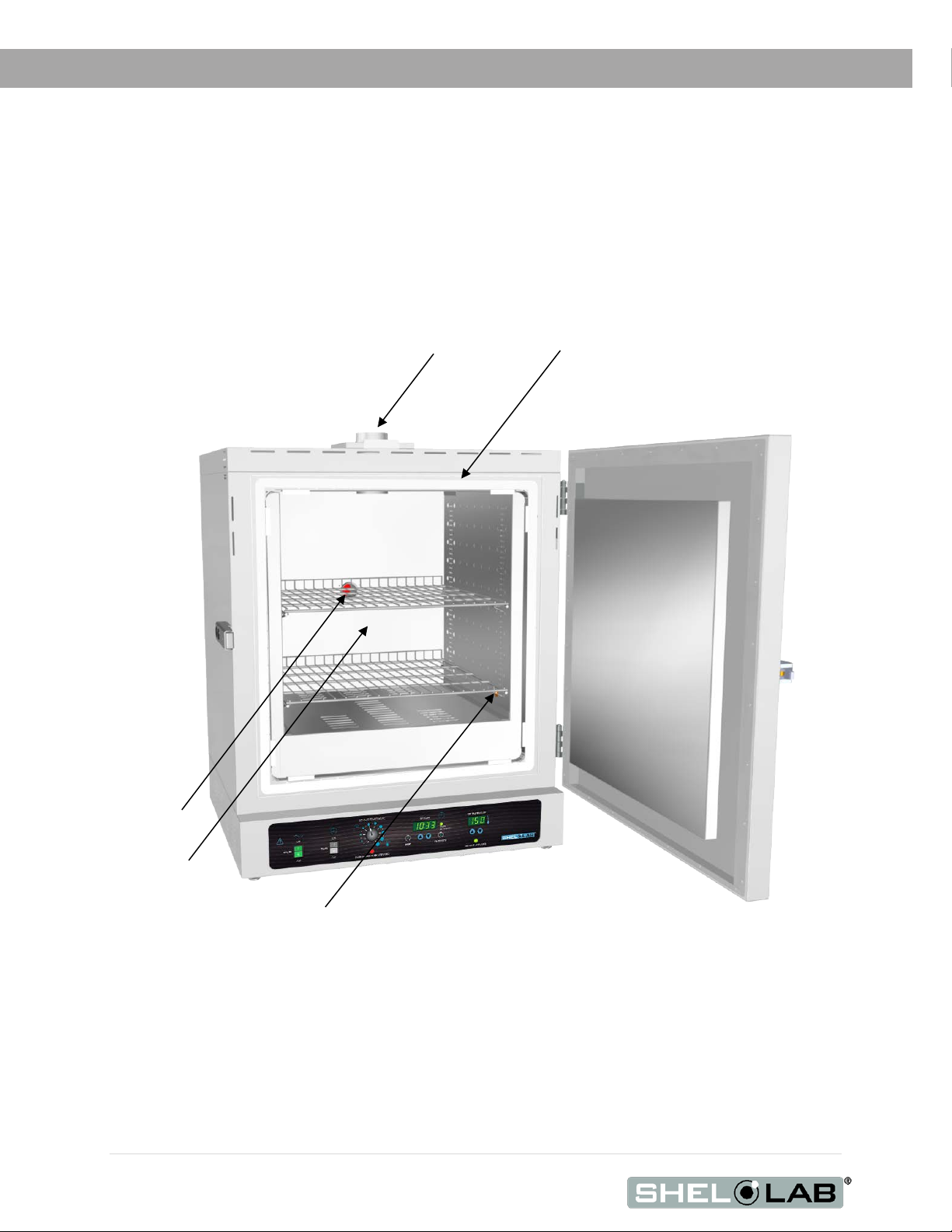
Figure
Exhaust Port with Sliding Dampener
Main Temperature and OTL Sensor Probes
Door Latch
Chamber
Chamber Gasket
Access Port
Oven Chamber
Control Panel
RECEIVING YOUR UNIT
ORIENTATION PHOTOS
1: SGO5
Door
Handle
10 | Page
Page 11
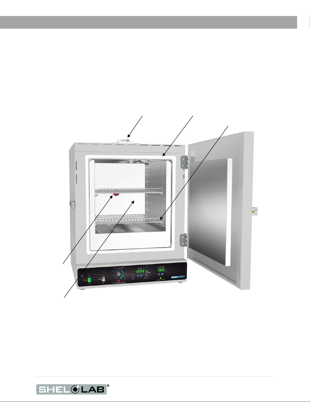
Figure
Exhaust Port with Sliding Dampener
Main Temperature
Door Latch
Chamber
Control Panel
Chamber Gasket
Access Port
Oven Chamber
RECEIVING YOUR UNIT
2: SGO3
and OTL Sensor
Probes
Door
Handle
11 | Page
Page 12
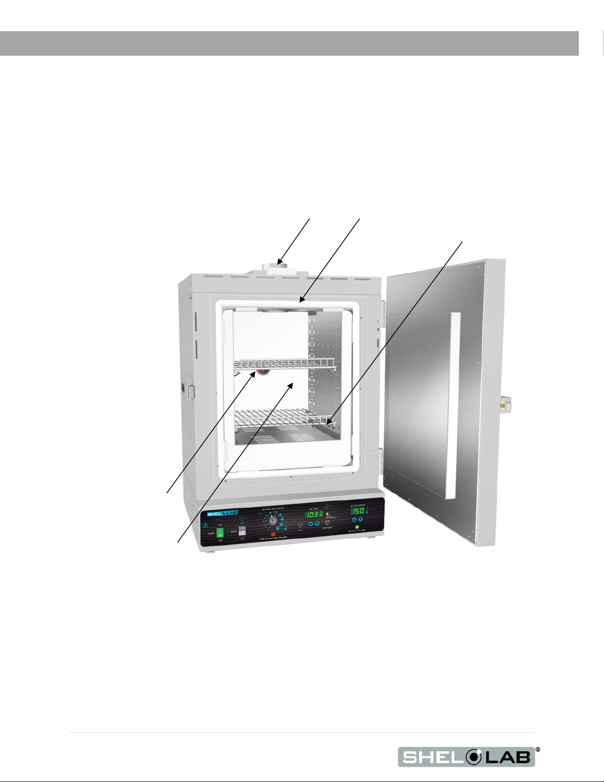
Figure
Door Latch
Control Panel
Access Port
Oven Chamber
Exhaust Port with Sliding Dampener
Chamber Gasket
Main Temperature
RECEIVING YOUR UNIT
3: SGO1
and OTL Sensor
Probes (Under Shelf)
12 | Page
Page 13
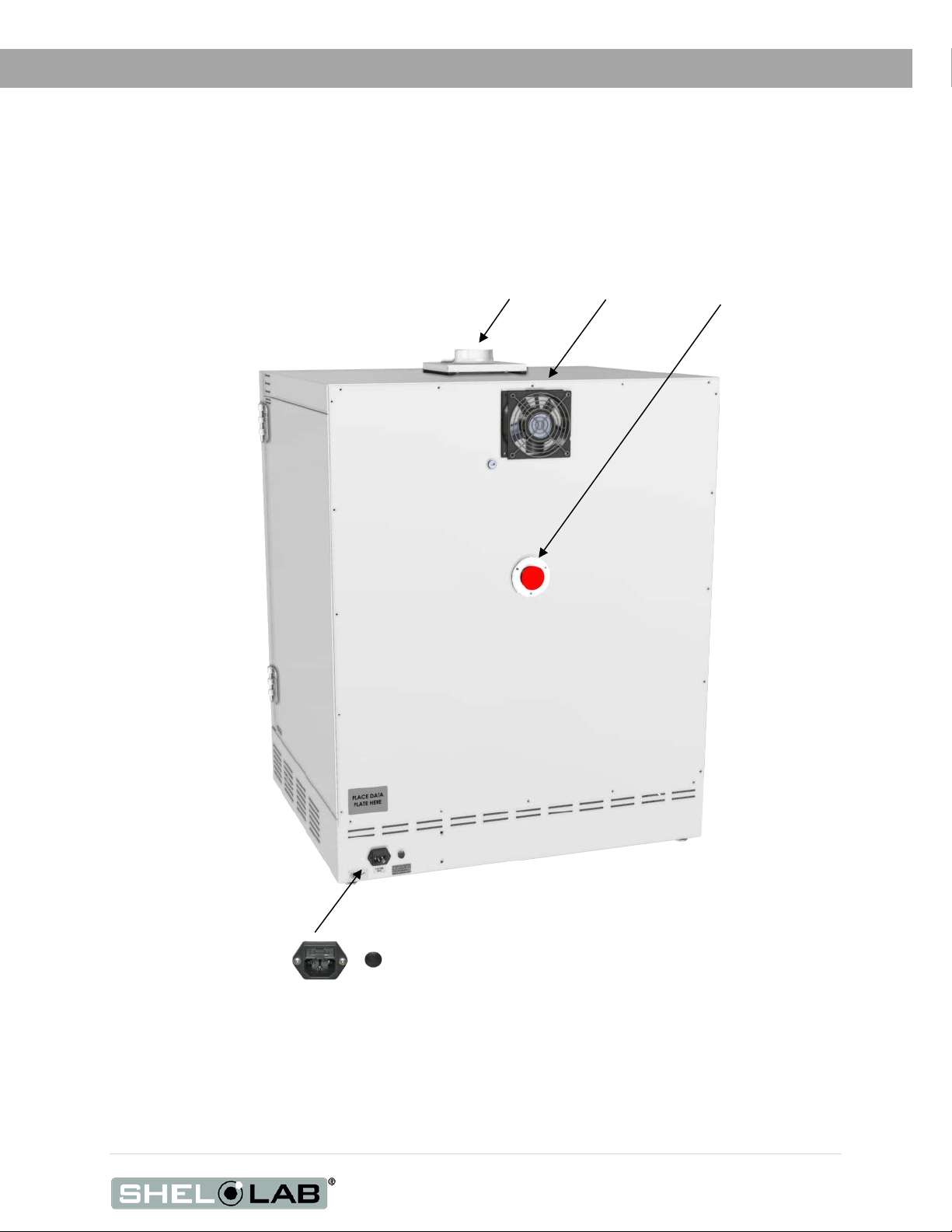
Figure
Exhaust Vent
Fan
Access Port (Stopper Installed)
Power Cord Inlet with Fuse
RECEIVING YOUR UNIT
4: Unit Back
13 | Page
Page 14
RECEIVING YOUR UNIT
RECORDING DATA PLATE INFORMATION
The data plate contains the unit model number and serial number. Tech Support will need this
information during any support call. Record it below for future reference.
• The data plate is located on the back of the oven above the power inlet.
Model Number
Serial Number
14 | Page
Page 15

INSTALLATION
INSTALLATION PROCEDURE CHECKLIST
For installing the oven in a new workspace.
Pre-Installation
Check that the required workspace ambient conditions for the unit are
met, page
• Unit dimensions may be found on page 41
Check that the required ventilation and spacing requirements are met,
page
Check that a suitable electrical outlet and power supply is present, page 17.
16.
16.
Installing the oven in a suitable workspace location
Review the lifting and handling instructions, page 18.
Install the unit in its workspace location, page 18.
Make sure the unit is level, page 18.
Set up the oven for use
Clean the unit chamber and shelving if needed, page 19.
Install the shelving in the unit chamber, page 20.
Verify the stopper is installed in the access port on the outside of the oven,
20.
page
15 | Page
Page 16

6” (152mm)
6” (152mm)
12” (305mm)
24” (610mm)
24” (610mm)
6” (152mm) Fan
Access Port
12” (305mm) if
Door Swing
INSTALLATION
REQUIRED AMBIENT CONDITIONS
When selecting a location to install the unit, look for sources of heat, cold, and moving air that can affect
the chamber temperature and atmospheric integrity:
• Proximity to other ovens, autoclaves, and any device that produces significant radiant heat
• High-traffic areas
• Direct sunlight
• Heating and cooling ducts or other sources of fast-moving air currents
This unit is intended for use indoors at room temperatures between 15°C and 40°C (59°F and
°F) and at no greater than 80% Relative Humidity (at 25°C / 77°F). Operating the unit outside of
104
these conditions may adversely affect its temperature range and stability.
REQUIRED VENTILATION CLEARANCES
These clearances are required for the oven to operate safely and meet its stated temperature
specifications.
ducting is attached.
• 24 inches (610mm) of headspace clearance is required between the exhaust vent and any
overhead cover or partition.
SGO1: 23” (585mm)
SGO3: 27” (686mm
SGO5: 32” (813mm)
o 12 inches (305mm) of vertical headspace clearance suffices if the oven exhaust is
vented from the workspace through a duct or other channeling.
• Do not place objects on top of the oven.
• Allow at least 6 inches (152mm) from the access port and fan vent on the back of the oven
to the nearest wall or partition. Keep the fan unobstructed at all times.
• The chamber access port is located on the back of the oven. Leave sufficient room for easy
access if oven operators will be using the port.
16 | Page
Page 17

12.0 Amps
14.0 Amps
14.0 Amps
Standard
INSTALLATION
POWER SOURCE REQUIREMENTS
When selecting a location for the unit, verify that each of the following requirements is satisfied:
Power Source: The wall power outlet must meet the power requirements listed on the unit data
plate. These units are intended for 110 – 120 VAC 50/60 Hz applications at the following
amperages:
SGO1 SGO3 SGO5
• Supplied voltage must not vary more than 10% from the data plate rating. Damage to the
unit may result if the supplied voltage varies more than 10%.
• The wall power source must be protective earth grounded.
• Use a separate circuit to prevent loss of the unit due to overloading or circuit failure.
• The recommended wall circuit breakers for these units are 15 amps.
• The wall power source must conform to all national and local electrical codes.
Power Cord
The unit must be positioned so that all users can quickly unplug the cord in the event of an
emergency.
• Each unit comes provided with a 125 volt, 15Amp, 9ft 5 in (2.86m) NEMA 5-15P power
cord.
• Always use this cord or an identical replacement.
Fuses
NEMA 5-15R
wall socket
These units ship with a fuse installed in a fuse holder next to the power cord inlet.
• The fuse must be installed and intact for the unit to operate.
• Always find and fix the cause of a blown fuse prior to putting the unit back into operation.
• Fuse type
o 250V, T16, 5X20mm
17 | Page
Page 18

INSTALLATION
LIFTING AND HANDLING
The unit is heavy. Use appropriate lifting devices that are sufficiently rated for the unit weight. Follow the
guidelines below when lifting the unit:
• Lift the unit only from its bottom surface.
• Doors, handles, and knobs are not adequate for lifting or stabilization.
• Restrain the unit completely while lifting or transporting so it cannot tip.
• Remove all moving parts, such as shelves and trays, and lock doors in the closed position
during transfers to prevent shifting and damage.
LEVELING
Install the leveling feet in the 4 corner holes on the bottom of the unit. The unit must be level and
stable for safe operation.
Note: To prevent damage when moving the unit, turn all 4 leveling feet so that the leg of each foot
sits inside the unit.
18 | Page
Page 19

INSTALLATION
INSTALL THE OVEN
Place the unit in a workspace location that meets the criteria discussed in the previous entries of the
Installation section.
DEIONIZED AND DISTILLED WATER
Do not use deionized water to clean the unit. Use of deionized water may corrode metal surfaces
and voids the warranty. The manufacturer recommends the use of distilled water in the resistance
range of 50K Ohm/cm to 1M Ohm/cm, or a conductivity range of 20.0 uS/cm to 1.0 uS/cm, for
cleaning.
INSTALLATION - CLEAN AND DISINFECT
Cleaning and disinfecting the unit chamber, shelving components, and ceiling air duct now reduces the
risk of contamination. The chamber and shelving were cleaned and disinfected at the factory, however,
the unit may have been exposed to contaminants during shipping.
• Remove all protective wrappings from shelving components and the ceiling air duct prior to
cleaning.
• See the Cleaning and Disinfecting entry on page 35 for information on how to clean and
disinfect without damaging the unit or its components.
19 | Page
Page 20

Figure
Figure
INSTALLATION
SHELVING INSTALLATION
1. Install 4 clips for each shelf in the slots located on the sides of the chamber interior.
a. Squeeze each clip.
b. Insert the top tabs first, then the bottom tabs using a rocking motion.
2. Place the shelf on the clips.
Figure 5: Install Clips
ACCESS PORT STOPPER
Verify the port stopper is installed in the access port on the back of
the unit. The oven will not meet its temperature performance
specifications without the stopper installed.
The stopper must always be installed on the outside of the oven.
Installing the stopper on the inside of the oven risks damaging the
stopper.
The intended use of the port is to introduce sensor probes into the
oven chamber.
6: Place the Shelf
7: Port Stopper in Access Port
20 | Page
Page 21

GRAPHIC SYMBOLS
The unit is provided with multiple graphic symbols on its exterior. The symbols identify hazards and
the functions of the adjustable components, as well as important notes in the user manual.
Symbol Definition
Consult the user manual
Consulter le manuel d'utilisation
Temperature display
Indique l'affichage de la température
Over Temperature Limit system
Thermostat température limite contrôle haute
Repère le courant alternatif
I/ON O/OFF
I indique que l'interrupteur est en position marche.
AC Power
O indique que le commutateur est en position d'arrêt.
Protective earth ground
Terre électrique
Indicates UP and DOWN respectively
Touches de déplacements respectifs vers le HAUT et le BA
Manually adjustable
Indique un réglage manuel
Recycle the unit. Do not dispose of in a landfill.
Reycle l'unité. Ne jetez pas dans une décharge.
Caution hot surface
Attention surface chaude
21 | Page
Page 22

GRAPHIC SYMBOLS
Symbol Definition
Indicates the timer
Indique le minuterie
Start or Stop the Timer
Lancer ou arrêter le minuteur
Reset the Timer
Réinitialisation de la Minuterie
22 | Page
Page 23

CONTROL PANEL OVERVIEW
Control Panel
Power Switch
When in the ON ( I ) position, the switch illuminates and the oven heats to the currently programmed
temperature set point.
Timer Switch
The black Timer Switch controls power to the timer system. When this switch is in the ON position,
the ovens ceases heating, the SET TIMER display illuminates, and the user may launch a timed,
steady-state heating profile running at the current temperature set point. The oven will not heat
while the Timer system is on unless a profile is launched.
Over Temperature Limit Control (OTL)
This graduated dial sets the temperature cutoff limit for the Over Temperature Limit system. The OTL
is an independent mechanical heating cutoff that prevents unchecked heating of the oven in the
event of a failure of the main temperature controller system. For more details, please see the
explanation of the Over Temperature Limit System on page 27 in the Theory of Operation entry.
Over Temperature Activated Light
Illuminates whenever the OTL system is routing power away from the heating elements. Under
normal operating conditions this light should remain off.
23 | Page
Page 24

CONTROL PANEL OVERVIEW
Timer Display and Control Pad
The SET TIMER display shows the duration of the currently programmed heating profile, or a flashing
duration adjustment mode, or the countdown of an active profile to 0.
The “//” RESET button is used to place the Timer display in its adjustable duration mode, and then to
scroll through the duration time parameters.
The SET TIMER arrow buttons adjust the heating profile duration time parameters when the display is
in its duration adjustment mode.
The “T” START/STOP timer button launches a heating profile or pauses an active profile.
Temperature Display and Control
Marked SET TEMPERATURE, this display shows the current oven chamber air temperature accurate
to within 1.0°C. The display can also show an adjustable temperature set point as well as an
adjustable chamber temperature value while in calibration mode.
The arrow buttons can be used to adjust the temperature set point or put the unit into its calibration
mode, and then enter a calibration offset value.
Heating Activated Light
The green light located beneath the label HEATING ACTIVATED illuminates whenever the oven
elements are powered and heating the oven chamber. The oven uses measured pulses to achieve
and maintain the temperature set point.
24 | Page
Page 25

OPERATION
Safe operation of the unit is dependent on the actions and behavior of the unit operators. Operating
personnel must read and understand the Operating Precautions in this section prior to operating
the unit. The operators must follow these instructions to prevent injuries and to safeguard their
health, environment, and the materials being treated in the unit, as well as to prevent damage to the
unit. Failure to adhere to the Safety Guidelines and Operating Cautions, deliberately or through
error, is a hazardous behavior on the part of the operator.
Le fonctionnement sûr du four dépend des actions et du comportement des opérateurs du four. Le
personnel d'exploitation doit lire et comprendre les consignes de sécurité et les précautions
d'utilisation de cette section avant d'utiliser le four. Les opérateurs doivent suivre ces instructions
pour prévenir les blessures et protéger leur santé, leur environnement et les matériaux traités dans
le four, ainsi que pour éviter d'endommager le four. Le non-respect des consignes de sécurité et des
précautions d'utilisation, délibérément ou par erreur, est un comportement dangereux de la part de
l'opérateur.
OPERATING PRECAUTIONS
• Do not use this oven in unsafe improper applications that produce flammable or combustible
gases, vapors, liquids, or fuel-air mixtures in quantities that can become potentially
explosive.
• Outgassed byproducts may be hazardous to or noxious for operating personnel. Exhaust
should be vented to a location outside the workspace in a safe manner in accordance with
all applicable laws, ordinances, and regulations. Do not operate the oven in an unsafe area
with noxious fumes.
• Do not use this oven for applications heating hazardous fibers or dust. These items can
become airborne and come into contact with hot surfaces.
• Individual ovens are not rated to be explosion proof. Follow all building certification
requirements and laws for Class I, II, or III locations as defined by the US National Electric
Code.
• The bottom surface of the chamber should not be used as a work surface. It runs hotter than
the shelf temperatures. Never place samples or product on the oven chamber floor.
• Do not place sealed or filled containers in the oven. These may burst open when heated.
• Do not place alcohol or mercury thermometers in the unit. These devices may rupture under
heat or other improper uses.
• Do not move the oven until it has finished cooling.
Warning: The vent dampers may be hot to the touch. These areas are marked with Hot Surface labels.
Proper PPE should be employed to minimize risk to burn.
Avertissement: Les clapets d'aération peuvent être chauds au toucher. Ces zones sont marqués avec des
étiquettes de Surface chaude. Les EPI approprié devraient être employée pour réduire au minimum le
risque de brûler.
25 | Page
Page 26

OPERATION
THEORY OF OPERATION
Heating
When powered, the oven chamber heats to and then maintains the currently programmed
temperature set point. The oven comes from the factory with a temperature set point of “OFF”. The
set point may be adjusted by the end-user using the Set Temperature controls.
The oven controller senses the chamber air temperature via a solid-state probe located in the
airstream on the right wall of the oven chamber. When the processor detects that the chamber
temperature has dropped below the temperature set point, it pulses power to a heating element in a
recirculation air duct space located above the oven chamber.
The processor employs proportional-integral-derivative analytical feedback-loop functions when
measuring and controlling the chamber air temperature levels. PID-controlled heating pulse
intensities and lengths are proportional to the difference between the measured chamber
temperature and the current set point. The frequency of pulses is derived from the rate of change in
the difference. The integral function slows the rate of pulses when the temperature nears the set
point to avoid overshooting.
SGO ovens rely on natural heat radiation for cooling. When the oven is powered, the chamber air
temperature cannot go below the ambient room temperature plus the internal waste heat of the
oven.
Air Circulation and Venting
SGO ovens rely on natural gravity convection for air circulation. Warm air rises and cooler air sinks in
the heated oven chamber.
The oven is provided with a dampener vent that may be opened or closed using a dampener slide
located on the oven top. SGO ovens must be run with the dampener 30% open in order to achieve
the stated temperature performance specifications.
Opening the vent all the way while the oven during a baking application may speed the rate of
material drying, depending on the nature of your application. However, it also introduces excessive
quantities of cool air into the chamber while allowing heated air to exit. This will likely impact the
temperature performance of the oven. For most applications, fully opening the vent after the baking
portion of the application will help to speed product or sample drying.
26 | Page
Page 27

OPERATION
Timed Heating Profile
The oven is provided with a Timer subsystem. When set, it runs the oven in a steady-state heating
profile at the current temperature set point for 1 minute up to 99 hours, 59 minutes. Allow the oven
to heat to the profile temperature prior to launching a profile. Launching a profile with the
temperature set point set to 150°C immediately after turning on the oven will result in the first several
minutes of the profile spent with the chamber rising from room temperature to 150°C.
When the Timer system is on, the oven will not heat unless a profile of 1 minute or greater has been
launched.
The Over Temperature Limit System (OTL)
When set, the mechanical OTL heating cutoff system prevents runaway heating in the oven chamber.
The OTL operates independently of the microprocessor and is provided with a separate, hydrostatic
temperature sensor probe located in the oven chamber. In the event the chamber air temperature
exceeds the current OTL setting, the OTL routes power away from the heating elements. The OTL
will continue to prevent heating until the temperature drops below its limit setting. The Over
Temperature Limit is set by the end-user, typically at approximately 5°C above the application
temperature set point.
27 | Page
Page 28
3. Set the Temperature Set Point to your baking application
4. Set the Over Temperature Limit Heating
Optional: Set the timer
OPERATION
Note: The oven may produce light smoking during its first use above 150°C as the remnants of a
protective oil coating burn off the heating element.
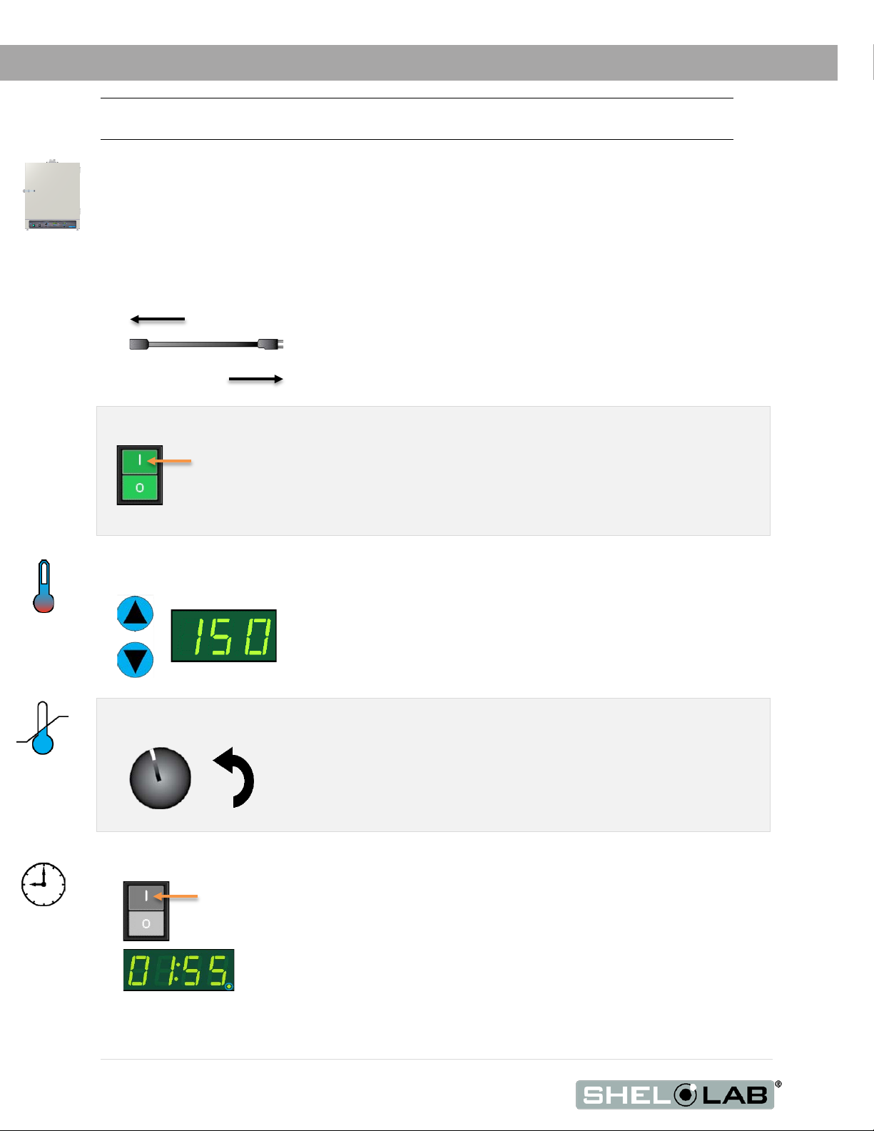
PUT THE OVEN INTO OPERATION
Carry out the following steps and procedures to put the oven into operation after installing it in a new
workspace environment.
1. Plug in the power cord
2. Power the oven
Place the oven Power Switch in the ON ( I ) position.
Attach the power cord that came with the unit to the power inlet
receptacle on the back of the oven.
Plug the power cord into the workspace electrical supply outlet.
• The switch and Temperature display will both illuminate
See the Set the Temperature the Set Point procedure on page 29.
See the Set the Over Temperature Limit on page 30.
• The oven must be heated and stable at your application
temperature prior to performing this procedure.
See the Set the Timer procedure on page 31.
28 | Page
End of procedure
Page 29
2.
Set Point Adjustment Mode
5. Wait 5 seconds after entering the Set Point
•
•
HEATING ACTIVATED
Current Set Point
OPERATION
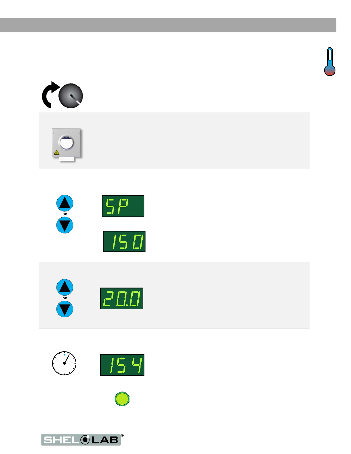
SET THE TEMPERATURE SET POINT
Set the oven to your application temperature.
1. Turn the OTL dial clockwise to its maximum position, if not already set to max.
• This prevents the heating cutoff system from interfering with this
procedure.
Open the vent (30% Open)
• The vent must be partly open to create convection in the oven
chamber.
• The oven will not achieve its specified temperature uniformity if the
vent is left closed or if it is fully open.
3. Navigate to the Temperature Set Point Adjustment mode
Press and
hold either
4. Adjust to your Temperature Set Point
Adjust
Set Temperature
New Set Point
End of Procedure
“SP” indicates set point.
Note: The display automatically exits the
adjustment mode after 5 seconds of
inactivity, saving the last shown set point
value.
The display stops flashing and
reverts to showing the current
chamber temperature.
The adjusted set point is now saved
in the controller.
29 | Page
Page 30
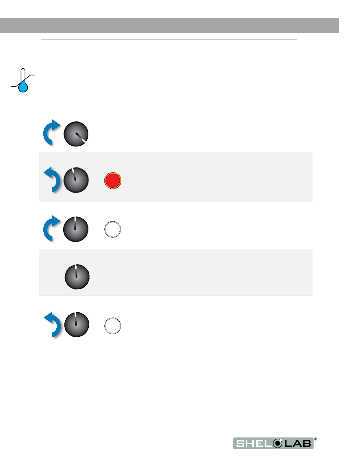
2. Turn the dial counterclockwise until the red Over Temperature Limit Light illuminates.
3.
4. Leave the OTL dial set just above the activation point.
Optional: Turn the dial slightly to the left.
•
OPERATION
Note: Test the OTL system at least once per year to verify its functionality
SET THE OVER TEMPERATURE LIMIT
This procedure sets the Over Temperature Limit heating cutoff to approximately 5˚C above the current
chamber temperature. Perform this procedure when the oven has been running with no
temperature fluctuations at your application temperature for at least 30 minutes.
1. Set OTL control to its maximum setting, if not already set to max.
Slowly turn the dial clockwise until the OTL Activated light turns off.
• The Over Temperature Limit is now set approximately 5˚C
above the current oven chamber air temperature.
If the OTL sporadically activates after setting the control, turn the dial very slightly to the right
(clockwise).
If the OTL continues activating, check for ambient sources of heat or cold that may be adversely
impacting the unit temperature stability. If you find no sources of external or internal temperature
fluctuations, contact Tech Support or your distributor for assistance.
This sets the OTL cutoff threshold nearer to the current
chamber air temperature.
End of procedure
30 | Page
Page 31
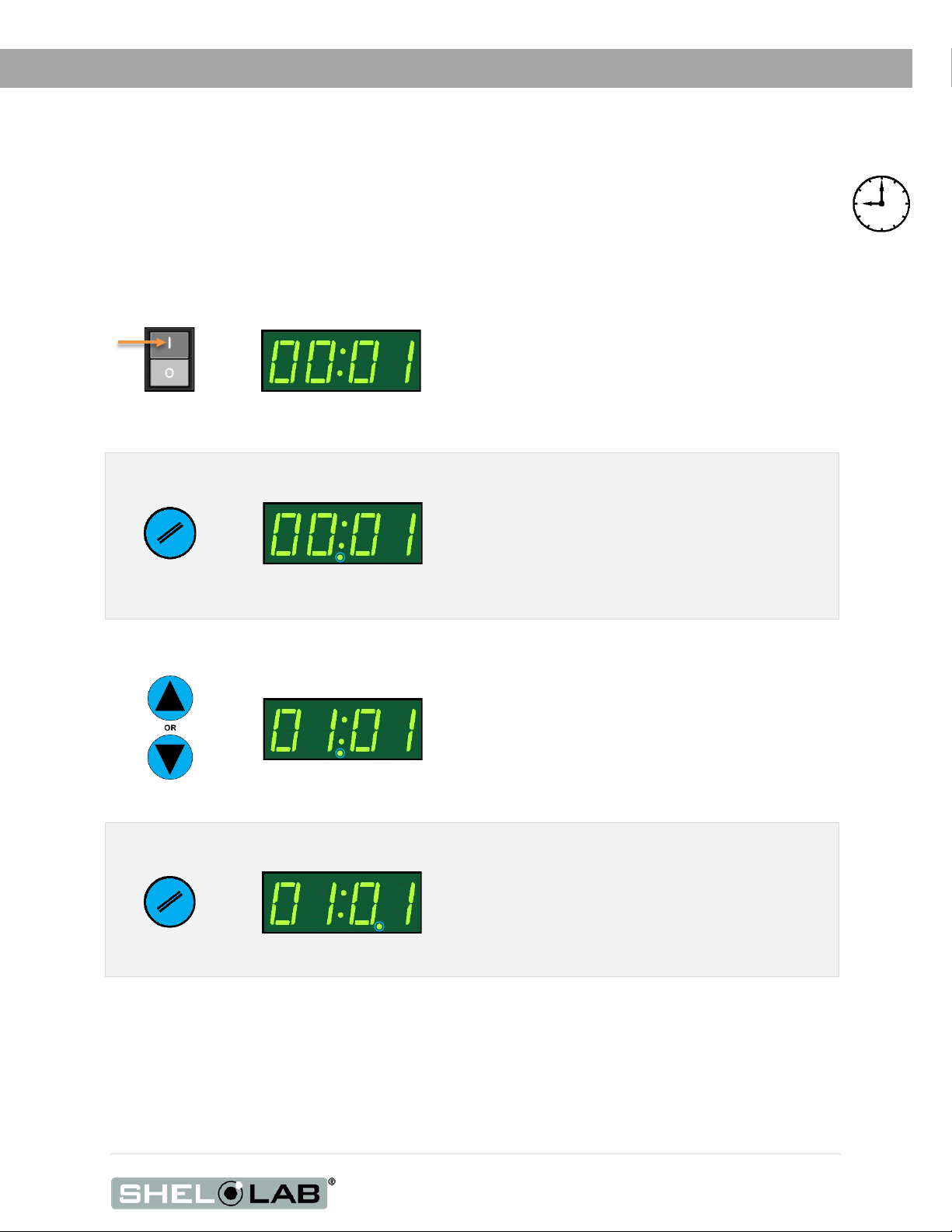
Set Timer
2. Place the Timer Display in its adjustable Set Timer mode
3. Set the Hour parameter
4. Advance to Tens-of-Minutes parameter
OPERATION
SETTING THE TIMER
This procedure enters a heating profile duration in the Timer system. When launched, the profile
runs the oven for the duration at the present temperature set point.
1. Turn on the Timer System
Push to On ( I )
Press and hold
RESET button
Adjust
1 Minute Profile
Hours Selected
1 Hour, 1 Minute
• The oven will cease heating
Note: The Timer will exit the adjustment
mode with the last entered time values
saved if 5 seconds elapse with no activity
on the Arrow Pad buttons.
Press
Tens of Minutes Selected
Continued on next page
Note: Advancing saves the adjusted
hour parameter.
31 | Page
Page 32

6. Advance to the Minutes parameter
7. Set the Minutes parameter
8. Wait for 5 seconds after entering the Minutes parameter
OPERATION
Set Timer (Continued)
5. Set the Tens-of-Minute parameter
Adjust
Press
Adjust
1 Hour, 51 Minutes
Minutes Selected
1 Hour, 55 Minutes
• The flashing decimal point advances to
between the third and fourth numbers.
• This saves the new Tens-of-Minutes
parameter setting.
5 Seconds
End of procedure
32 | Page
• The display exits adjustment mode.
• The minutes parameter is now saved.
Page 33

Set Timer
2.
Optional: Pausing a running profile
OPERATION
LAUNCHING A HEATING PROFILE
Allow the oven to come up to temperature prior to launching a profile. See the Setting the Timer
procedure on page 31 for how to set the length of the profile.
Note: While the Timer system is on, the oven will not heat unless a profile is running.
1. Turn on the Timer System
Push to On ( I )
Launch the current profile
Press and Hold
Push
• The Timer Display will illuminate, showing
the previously programmed profile duration.
1 Hour, 55 Minute Profile
• The oven will cease heating until the profile is restarted, reset, or the
Timer system is turned off.
• To continue the profile where it left off, press the Start/Stop “T” button
again.
• The oven will cease heating
• The Timer Display will start counting down.
• The oven will resume heating.
3. The oven ceases heating upon reaching “00:00”
Profile Complete
To resume heating, place the Timer Switch in
the OFF ( O ) position.
End of procedure
To launch another profile, press the “//” Reset
button and enter a new profile, or allow the
previous profile to reset automatically after 5
seconds.
33 | Page
Page 34

Figure
Figure
OPERATION
HIGH EXTERIOR TEMPERATURES
Note: Allow the oven to cool or use appropriate PPE and tools when adjusting the chamber gasket
seating.
If the chamber gasket comes out of alignment, oven chamber air may be drawn into the insulating
baffle spaces. This can result in heating of the oven exterior surfaces.
If the oven exterior is unusually warm or hot, push the chamber gasket inward along its entire length
to restore the integrity of the seal.
8: Chamber Gasket Misaligned
9: Chamber Gasket Aligned
DRYING RACKS AND OTHER ACCESSORIES
Make sure that any accessories used inside the oven chamber, such as drying racks, are suitable for
your application and will not suffer damage when brought to temperature. Always set the OTL cutoff
system to approximately 5°C above your application temperature set point in order to safeguard
accessories against over temperature events. The manufacturing defect warranty does not cover
damage caused by melted or otherwise overheated accessory items.
34 | Page
Page 35

USER MAINTENANCE
Warning: Prior to maintenance or service on this unit, disconnect the power feed from the power supply.
Avertissement: Avant d'effectuer toute maintenance ou entretien de cet appareil, débrancher le cordon
secteur de la source d'alimentation.
CLEANING AND DISINFECTING
If a hazardous material or substance has spilled in the unit, immediately initiate your site’s Hazardous
Material Spill Containment protocol. Contact your local Site Safety Officer and follow instructions per
the site policy and procedures.
• The unit chamber should be cleaned prior to first use.
• Periodic cleaning is required.
• Do not use spray on cleaners or disinfectants. These can leak through openings and
coat electrical components.
• Consult with the manufacturer or their agent if you have any doubts about the
compatibility of decontamination or cleaning agents with the parts of the equipment or
with the material contained in it.
• Do not use cleaners or disinfectants that contain solvents capable of harming paint
coatings or stainless steel surfaces. Do not use chlorine-based bleaches or abrasives;
these will damage the chamber liner.
Warning: Exercise caution if cleaning the unit with alcohol or flammable cleaners. Always allow the
unit to cool down to room temperature prior to cleaning and make sure all cleaning agents have
evaporated or otherwise been completely removed prior to putting the unit back into service.
Avertissement: Soyez prudent lorsque vo us nettoyez l'apparei l avec d e l'alcool ou des prod uits de
nettoyage inflamm ables. Laissez toujours refroidir l'appareil à la température ambiante avant le
nettoyage et assurez-vous que tous les produits de nettoyage se sont évaporés ou ont été
complètement enlevés avant de remettre l'appareil en service.
Cleaning
1. Disconnect the unit from its power supply.
2. Remove all removable interior components such as shelving and accessories.
3. Clean the unit with a mild soap and water solution, including all corners.
o Do not use an abrasive cleaner, these will damage metal surfaces.
o Do not use deionized water to rinse or clean with.
o Take special care when cleaning around the temperature sensor probes in the
chamber to prevent damage. Do not clean the probes.
4. Rinse with distilled water and wipe dry with a soft cloth.
35 | Page
Page 36

USER MAINTENANCE
Disinfecting
Disinfect the oven if algae, mold, bacteria, or other biological contaminants are an issue. For
maximum effectiveness, disinfection procedures are typically performed after cleaning.
Keep the following points in mind when disinfecting the unit:
• Turn off and disconnect the unit to safeguard against electrical hazards.
• Disinfect the unit chamber using commercially available disinfectants that are non-corrosive,
non-abrasive, and suitable for use on stainless steel and glass surfaces. Contact your local
Site Safety Officer for detailed information on which disinfectants are compatible with your
applications.
• If permitted by your protocol, remove all removable interior accessories (shelving and other
non-attached items) from the chamber when disinfecting.
• Disinfect all surfaces in the chamber, making sure to thoroughly disinfect the corners.
Exercise care to avoid damaging the sensor probes.
• When disinfecting external surfaces, use disinfectants that will not damage painted metal,
glass, and plastic.
GASKETS AND CHAMBER INTEGRITY
Periodically, inspect the door latch, trim, catch, and the gasket for signs of deterioration. Failure to
maintain the integrity of the door system shortens the life span of the oven.
These ovens use snap-in fiberglass chamber gaskets. The only tool required for swapping out these
gaskets is a cutting implement for tailoring the length of the new gasket. Use proper PPE for handling
exposed fiberglass when making the cuts.
ELECTRICAL COMPONENTS
Electrical components do not require maintenance. If the unit fails to operate as specified, please
contact your SHEL LAB distributor or Technical Support for assistance.
36 | Page
Page 37

2. Position the sensor probes in the chamber.
Heat-resistant
1. Introduce the reference device thermocouple
3. Carefully place the port stopper over
2” (51mm)
2” (51mm)
2” (51mm)
Shelf
Corner
4. The exhaust vent should be opened
USER MAINTENANCE
CALIBRATE THE TEMPERATURE DISPLAY
Note: Please see the Reference Sensor Device entry on page 7 for the device requirements.
Temperature calibrations match the temperature display to the actual air temperature inside the unit
chamber. The actual air temperature is supplied by a reference sensor device. Calibrations
compensate for software drifts in the controller as well as deviations caused by the natural material
evolution of the sensor probe in the heated chamber space. Calibrate as often as required by your
laboratory or production protocol, or regulatory compliance schedule. Always calibrate to the
industry or regulatory standards required for your application.
A Suggested Calibration Set Up
sensor probes into the oven chamber through
the access port.
• The probes may also be introduced
through the chamber door space.
• The probe heads must be at least 2
inches (51mm) in diagonally from the
shelf corners and 2 inches (50mm)
above the the shelving to prevent
heatsinking.
• Place 1 probe head as close as possible
to the geometric center point of the
chamber.
o If using a single thermocouple,
place the probe head as close
as possible to the geometric
center of the oven chamber.
• Secure probes with non-stick, heat-
resistant tape.
non-stick tape
recommended
the probe wires. Use heat-resistant,
nonmarking tape to secure the wires
and seal any exterior gaps
.
to match your application position. The
manuracturer recommmends a 30%
opening to meet the stated oven
uniformity specifications.
5. The oven chamber door must be
fully closed and latched.
37 | Page
Page 38

Begin Calibration
150°C
Start
30 Minutes Elapsed
See the Unit Specifications
USER MAINTENANCE
Heat up and stabilization period
• The oven chamber temperature must be stable to perform an accurate calibration.
• The temperature is considered stabilized when the oven chamber has operated at your
calibration temperature for at least 1 hour with no fluctuations greater than the specified
temperature stability of the oven (see the Unit Specifications chapter).
• The manufacturer recommends calibrating at your application temperature.
chapter for the oven Time to
Temperature heat up rates.
Fluctuations
(Exaggerated)
(Minimum)
Heat Up and Stabilization Phases
Suggested Calibration Procedure
1
Once the chamber has stabilized, compare the reference temperature
device and chamber temperature display readings.
• If the readings are the same, or the difference between the
two falls within the acceptable range of your protocol, the
display is accurately showing the unit chamber air
temperature. The Temperature Calibration procedure is
now complete.
-OR-
• See the next step if a difference falls outside the acceptable
range of your protocol.
2
Reference Device
Set Temperature
Reference Device
A display calibration adjustment must be entered to match the
display to the reference device. See next step.
38 | Page
Set Temperature
Continued on next page
Page 39

Calibration continued
USER MAINTENANCE
3
Place the oven in temperature calibration mode.
a. Press and hold both the UP and DOWN arrow buttons
simultaneously for approximately 5 seconds.
• The Temperature Display will show the letters “C O”,
then begin flashing the current temperature value.
Note: If an arrow key is not pressed for 5 seconds, the Temperature
Display will cease flashing and store the last displayed value as the
new current chamber temperature.
Current Temp. Value
4
5
6
Use the UP or DOWN arrows to adjust the current display
temperature value until it matches the reference device
temperature reading.
After matching the display to the reference device, wait 5
seconds.
• The temperature display will cease flashing and store
the correction as an offset.
• The oven will now begin heating or passively cooling
to reach the set point with the corrected display value.
Wait for 30 minutes for the oven to stabilize, after the
oven has achieved the set point with the corrected
display value.
• Failure to wait until the oven is fully stabilized will
result in an inaccurate reading.
Reference Device
Corrected
Heating with Corrected
Value
Set Point Achieved
Continued on next page
39 | Page
Page 40

USER MAINTENANCE
Calibration continued
7
Compare the reference device reading with the chamber display
again.
• If the reference device and the chamber temperature
display readings are the same, or the difference falls within
the range of your protocol, the unit is now calibrated for
temperature.
-OR-
• See the next step if the readings still fail to match or fall
outside of your protocol range.
Reference Device
8
If the two readings are not the same, and the difference still falls
outside the acceptable range of your protocol, repeat steps 3 - 7
up to two more times.
• Three attempts may be required to successfully calibrate
units that are more than ±2°C out of calibration.
If the temperature difference between the unit and reference device readings fall outside your
protocol after three calibration attempts, contact Technical Support or your distributor for assistance.
End of procedure
Reference Device
40 | Page
Page 41

UNIT SPECIFICATIONS
These ovens are 110 – 120 volt units. Please refer to the oven data plate for individual electrical
specifications.
Technical data specified applies to units with standard equipment at an ambient temperature of 25°C
and at nominal voltage. The temperatures specified are determined in accordance to factory
standard following DIN 12880 respecting the recommended wall clearances of 10% of the height,
width, and depth of the inner chamber. All indications are average values, typical for units produced
in the series. We reserve the right to alter technical specifications at all times.
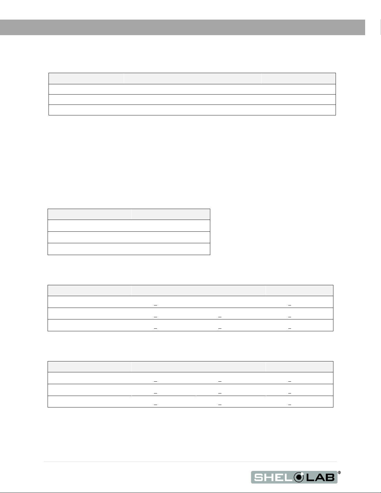
WEIGHT
Model Shipping Net
SGO1 146 lb / 66 kg 126.5 lb / 57.4 kg
SGO3 203 lb / 92 kg 170.5 lb / 77.3 kg
SGO5 243 lb / 110 kg 208.0 lb / 94.3 kg
DIMENSIONS
By Inches
Model Exterior W × D × H Interior W × D × H
SGO1 22.7 x 23.5 x 31.5 12.1 x 13.7 x 14.5
SGO3 26.9 x 28.6 x 34.0 16.5 x 19.5 x 16.2
SGO5 31.4 x 28.1 x 38.8 21.0 x 19.4 x 20.7
By Millimeters
Model Exterior W × D × H Interior W × D × H
SGO1 577 x 596 x 800 307 x 349 x 368
SGO3 684 x 727 x 840 419 x 495 x 412
SGO5 798 x 714 x 986 533 x 494 x 527
CAPACITY
Model Cubic Feet Liters
SGO1
SGO3
SGO5 4.9 138.0
1.4 39.4
3.0 85.0
41 | Page
Page 42
UNIT SPECIFICATIONS
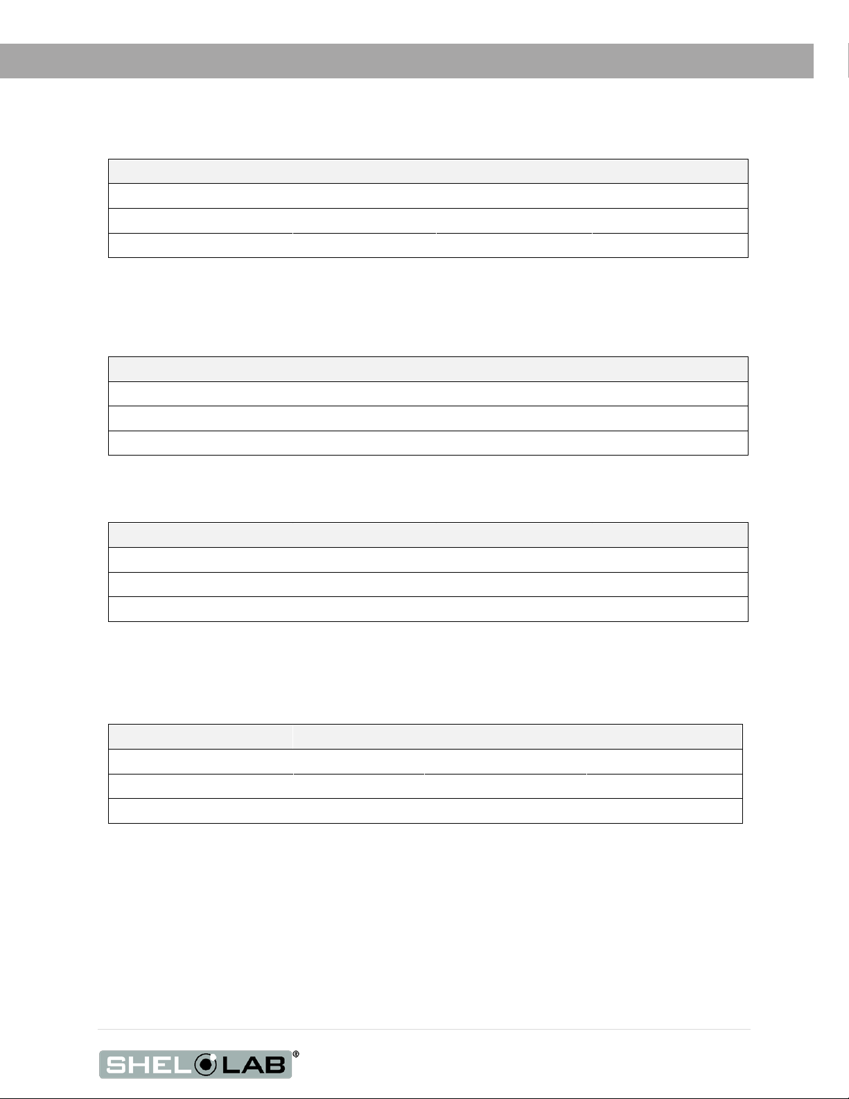
SHELF CAPACITY BY WEIGHT
Model Per Shelf Max Total Load Max Shelves
SGO1
SGO3
SGO5
*50 lb / 22.6 kg with weight evenly distributed across the shelf.
**100 lb / 45.3 kg total load for the SGO1 shelves. Exceeding this limit risks damaging the chamber liner.
***200 lb / 91.0 kg total load for the SGO3 and SGO5 shelves. Exceeding this limit risks damaging the chamber liner.
TEMPERATURE
50.0 lb / 22.6 kg* 100.0 lb / 45.3 kg** 6 Shelves
50.0 lb / 22.6 kg* 200.0 lb / 91.0 kg*** 7 Shelves
50.0 lb / 22.6 kg* 200.0 lb / 91.0 kg*** 9 Shelves
Range
Stability
Uniformity
Model Operating Range
SGO1
SGO3
SGO5
Model Stability @80°C Stability @150°C Stability @306°C
SGO1
SGO3
SGO5
Model Uniformity @80°C Uniformity @150°C Uniformity @306°C
SGO1
Ambient +20 to 306°C
Ambient +20 to 306°C
Ambient +20 to 306°C
+ 0.2°C
+ 0.2°C + 0.3°C + 0.4°C
+ 0.2°C + 0.3°C + 0.4°C
+ 2.5°C
± 0.3°C + 4.0°C
+ 3.5°C + 4.0°C
42 | Page
SGO3
SGO5
+ 2.5°C + 3.5°C + 4.0°C
+ 2.5°C + 3.5°C + 4.5°C
Temperature continued on next page
Page 43
UNIT SPECIFICATIONS
Time to Temperature: From an ambient temperature of 20°C.
Model Heat Up to 80°C Heat Up to 150°C Heat Up to 306°C
SGO1 5 Minutes
SGO3 7 Minutes 23 Minutes 95 Minutes
SGO5 18 Minutes 30 Minutes 120 Minutes
Recovery Time: From a 30-second door opening.
Model Recovery to 80°C Recovery to 150° Recovery to 306°C
SGO1 2.5 Minutes
SGO3 3.0 Minutes 4.0 Minutes
SGO5 4.0 Minutes 8.0 Minutes
Recovery Time: From a 60-second door opening.
Model Recovery to 80°C Recovery to 150° Recovery to 306°C
SGO1 3.0 Minutes 4.0 Minutes
SGO3 5.0 Minutes
SGO5 5.0 Minutes 15.0 Minutes
21 Minutes 68 Minutes
3.5 Minutes
5.5 Minutes
18.0 Minutes
24.0 Minutes
35.0 Minutes
22.0 Minutes
37.0 Minutes
68.0 Minutes
POWER
Model AC Voltage Amperage Frequency
SGO1
SGO3
SGO5
110 – 120 12.0 50/60 Hz
110 – 120 14.0 50/60 Hz
110 – 120 14.0 50/60 Hz
43 | Page
Page 44

UNIT SPECIFICATIONS
44 | Page
Page 45
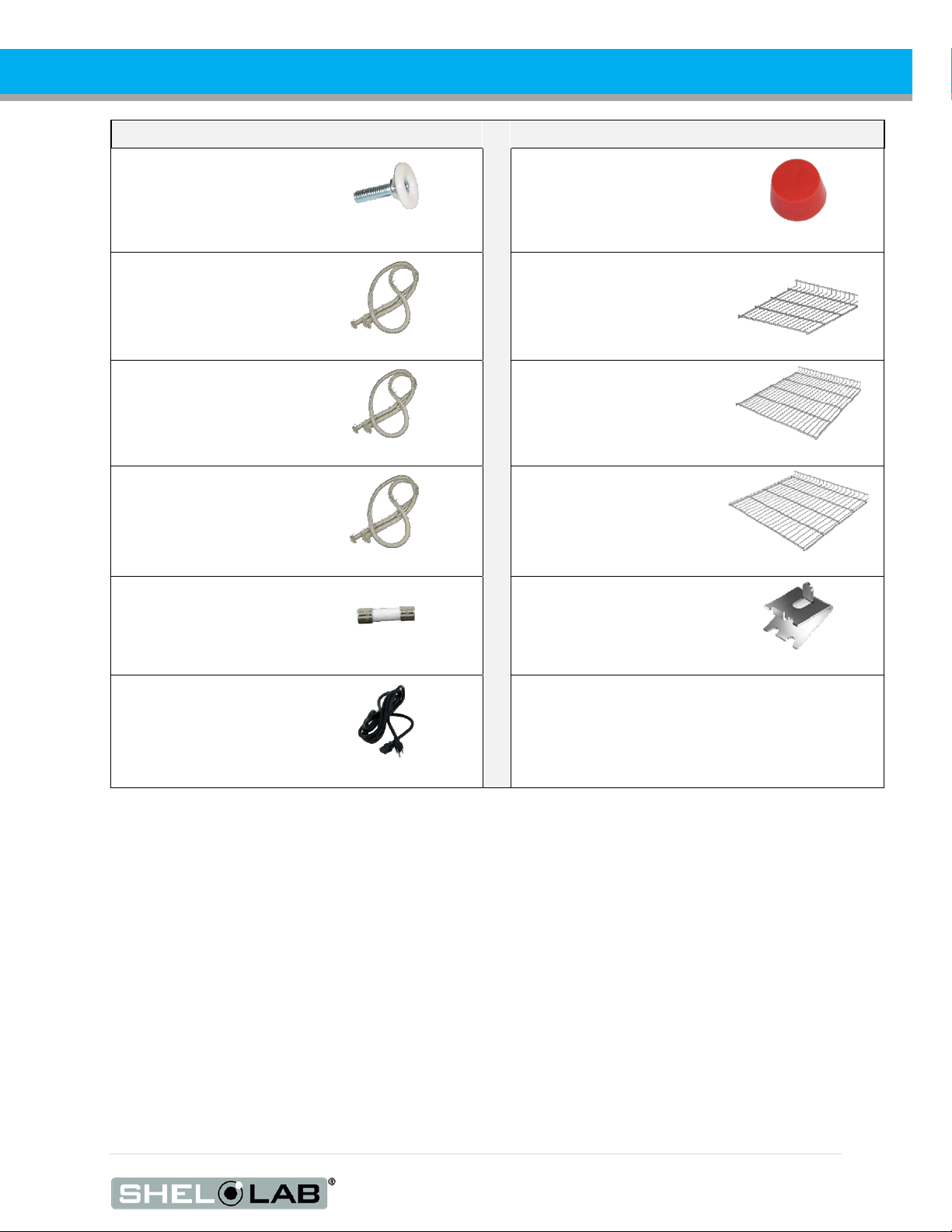
PARTS LIST
Description Parts Number Description Parts Number
Adjustable Leveling Foot
Chamber Gasket, SGO1,
sold by 1.5 feet, requires
5.4ft (1.65 meters)
Chamber Gasket, SGO3,
sold by 1.5 feet, requires
7.5ft (2.3 meters)
Chamber Gasket, SGO5,
sold by 1.5 feet, requires
8.1ft (2.5) meters
Fuse, T16A 250V 5x20mm
2700512
3450767 (1.5ft)
3450767 (1.5ft)
3450767 (1.5ft)
3300513
Port Stopper, High
Temperature
7750572
Shelf, SGO1
6800543
Shelf, SGO3
6800544
Shelf, SGO5
6800454
Shelf Clip, Individual (1)
1250512
Power Cord 125 volt,
15Amp, 9ft 5 in (2.86m)
NEMA 5-15P
1800510
Ordering
If you have the Part Number for an item, you may order it directly from Sheldon Manufacturing by
calling 1-800-322-4897 extension 3. If you are uncertain that you have the correct Part Number, or if
you need that specific item, please contact Sheldon Technical Support for help at 1-800-322-4897
extension 4 or (503) 640-3000. Please have the model number and serial number of the unit ready,
as Tech Support will need this information to match your unit to its correct part.
45 | Page
Page 46

PARTS LIST
46 | Page
Page 47

PARTS LIST
47 | Page
Page 48

P.O. Box 627
Cornelius, OR 97113
USA
support@sheldonmfg.com
sheldonmanufacturing.com
1-800-322-4897
(503) 640-3000
FAX: 503 640-1366
 Loading...