

Page 1

1-800-322-4897
(503) 640-3000
FAX (503) 640-1366
BACTROX HYPOXIC CHAMBERS
OPERATION MANUAL
MODEL: BACTROX
Sheldon Manufacturing Inc. P.O. Box 627 Cornelius, Oregon 97113
EMAIL: tech@Shellab.com INTERNET: http://www.Shellab.com
Rev 8/ 25/2014
4861671
Page 2

__________________________________________________________________________
Contents
OPERATION MANUAL .................................................................................................. 1
1. ORIENTATION ............................................................................................................... 3
2. RECEIVING AND INSPECTION .................................................................................... 6
3. INSTALLATION .............................................................................................................. 6
4. CONTROL PANEL OVERVIEW ..................................................................................... 8
5. HOSE AND ELECTRICAL CONNECTIONS .................................................................. 8
6. THERMOELECTRIC CONDENSATE CONTROLER .................................................... 9
7. INCUBATOR TEMPERATURE CONTROLLER/SET OVER TEMPERATURE ............ 9
8. CO2 CONTROL CALIBRATION .................................................................................. 10
9. OXYGEN CONTROL CALIBRATION .......................................................................... 11
10. POWER ON THE BACTROX: ...................................................................................... 13
11. MAKING THE CHAMBER HYPOXIC ........................................................................... 14
12. PASS BOX OPERATION ............................................................................................. 14
13. ENTERING THE CHAMBER ........................................................................................ 15
14. EXITING THE CHAMBER ............................................................................................ 15
15. MAINTENANCE ........................................................................................................... 15
16. ACCESSORIES ............................................................................................................ 16
17. TROUBLESHOOTING ................................................................................................. 17
18. BACTROX OPERATION TIPS ..................................................................................... 19
19. UNIT SPECIFICATIONS .............................................................................................. 20
20. DIAGRAMS .................................................................................................................. 21
21. PLUMBING DIAGRAM ................................................................................................. 31
22. BACTROX SPARE PARTS LIST ................................................................................. 32
Bactrox Operations Manual 2
Page 3
__________________________________________________________________________
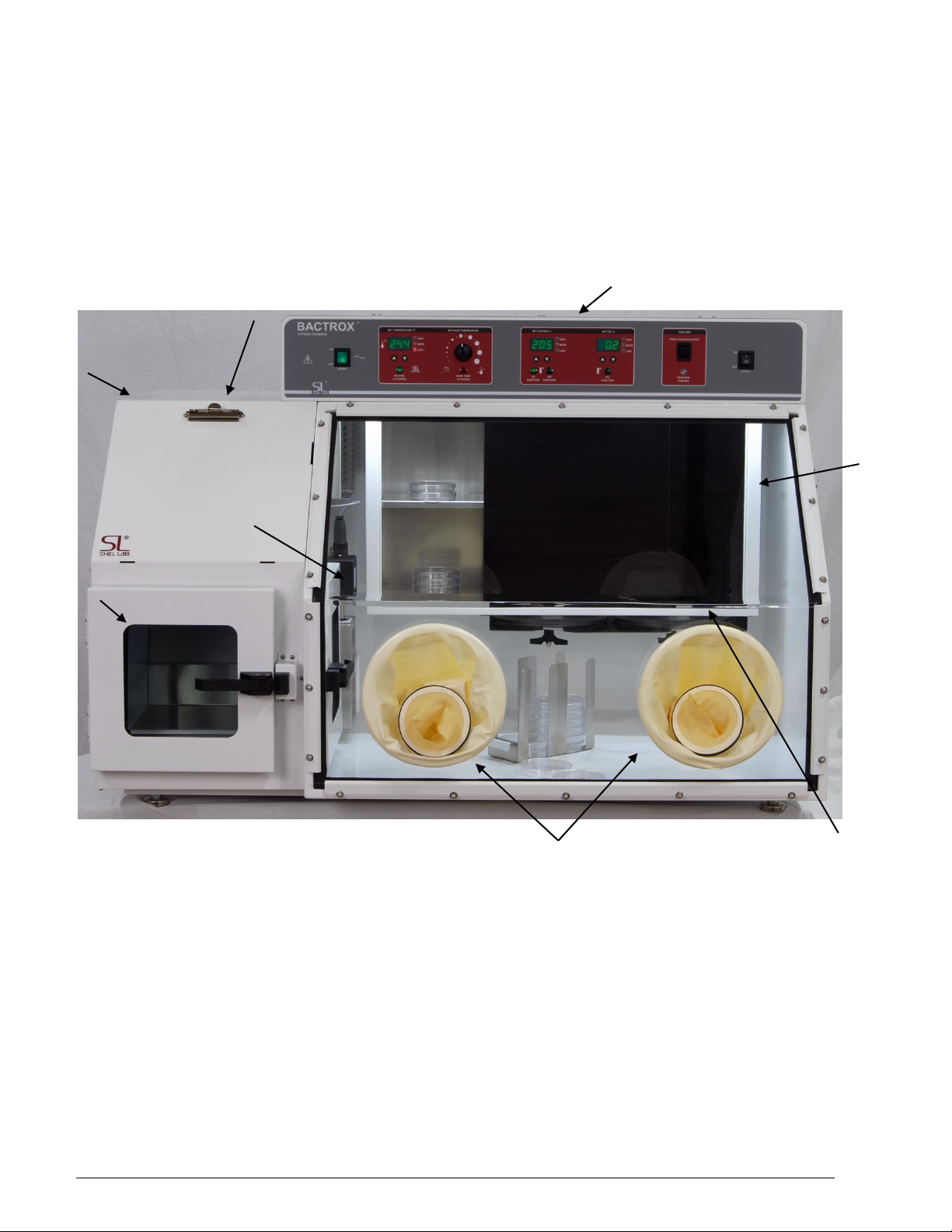
Document/Chart
holder
Pass Box
GAS
Connections
Incubator
Arm Port Door
Storage
Arm Ports
With Sleeve
Control Panel
Oxygen
Sensor &
Box
IMPORTANT: READ THIS INSTRUCTION MANUAL IMMEDIATELY.
Your satisfaction and safety require a complete understanding of this unit, including its proper function and
operational characteristics. Be sure operators are given adequate training before attempting to put the unit in
service. NOTE: This equipment must be used only for its intended application; any alterations or
modifications will void your warranty.
1. ORIENTATION
Bactrox Operations Manual 3
Page 4
__________________________________________________________________________
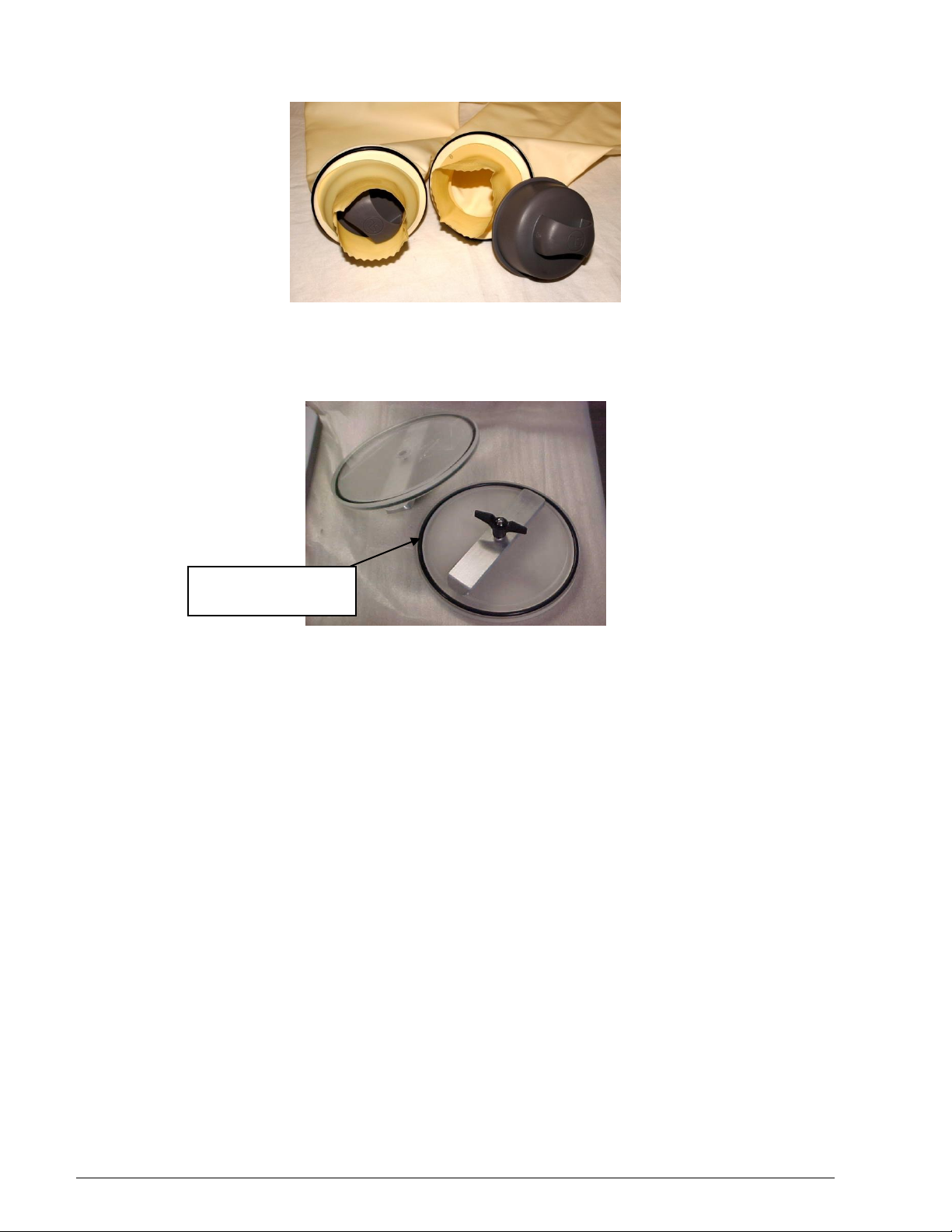
Replaceable Arm Port
door O-ring seals.
Figure 1: Sleeve/Cuff Assembly
The Sleeve/Cuff Assembly consists of a neoprene sleeve, a plastic cuff ring, O-Ring, and a soft rubber cuff. Unit
comes with Latex Gloves and Cuffs. Nitrile Gloves and Cuffs may be ordered from the Parts List. The assembly
allows gloveless chamber operation.
Figure 2: Arm port Doors
CAUTION: The Bactrox chambers have an efficient method of sealing the chamber by utilizing the Arm port
doors as shown in Figure 3. The tightening knob on the Arm port doors should be turned just until the knob
begins to “grab”. DO NOT OVER TIGHTEN. Damage can occur if too much force is placed on the Arm port door
assembly.
Bactrox Operations Manual 4
Page 5
__________________________________________________________________________
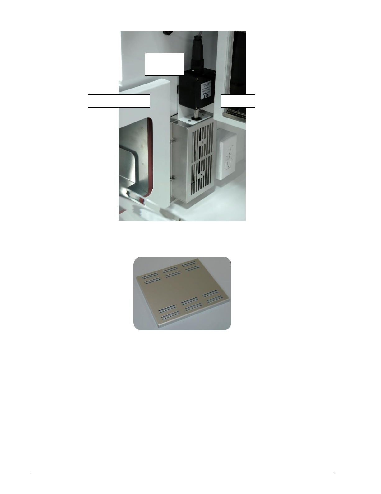
Inner Airlock Door
Oxygen
Sensor and
Box
Incubator
Figure 5. Pass Box
The PASS BOX provides ability to take material into and out of the chamber. PASS BOX can be operated either
automatically or manually. The PASS BOX shelf allows for materials to be conveniently rolled from the PASS
BOX into the chamber.
Figure 6: Incubator Bottom Shelf Spacer
Three (3) are provided with the Bactrox. Refer to Section 8 for installation and precautions.
Bactrox Operations Manual 5
Page 6

__________________________________________________________________________
2. RECEIVING AND INSPECTION
2.1 The carrier, when accepting shipment, also accepts responsibility for safe delivery and is liable
for loss or damage claims. On delivery, you must inspect for visible exterior damage. Note and
describe on the freight bill any damage found and enter your claim on the form the carrier
supplies.
2.2 Inspect for concealed loss or damage on the unit itself, both interior and exterior. If any, the
carrier will arrange for official inspection to substantiate your claim. Save the shipping crate until
you are sure the unit has been delivered in good condition.
2.3 If for any reason you must return the unit, contact your sales representative for authorization and
supply nameplate data.
3. INSTALLATION
3.1 Local city, county, or other ordinances may govern the use of this equipment. If you have any
questions about local requirements, please contact the appropriate local agency.
3.2 Under normal circumstances these units are intended for use indoors, at room temperatures
between 5 and 40C, at no greater than 80% relative Humidity (at 25C) and with a supply
voltage that does not vary by more than 10%. These chambers should not be operated at an
altitude exceeding 2000 meters. Installation category is CAT-II.
3.3 Pollution Degree 2. Customer service should be contacted for operating conditions outside of
these limits. Installation may be performed by the end user. It is unnecessary for this unit to be
installed by a technician.
3.4 Location: In selecting a location, consider all conditions that might affect performance, such as
heat from radiators, ovens, autoclaves, etc. Avoid direct sun, UV light sources, fast-moving air
currents, heating and cooling ducts, and high traffic areas. Allow a minimum of 10 cm between
the unit and any walls or partitions that might obstruct free airflow and to promote easy access to
the power cord and source. Under normal circumstances this unit is intended for use indoors.
3.5 Power Source: The unit power requirements are listed on the data plate. Check the data plate
for voltage, cycle, and ampere requirements. Plug the power cord into a PROPERLY
GROUNDED (earthed) Power source OF THE CORRECT SIZE AND STYLE INDICATED ON
THE UNIT NAMEPLATE RATING. A separate circuit is recommended for this unit to prevent
loss of product due to overloading or circuit failures caused by other equipment. The supply
voltage must match the nameplate voltage within +/- 10%. The US market units are designed for
120 VAC @ 60 Hz, 12.0 Amps. The EU market units are designed for 230 VAC @ 50/60Hz, 6.0
Amps. If supplied with a detachable cord set, plug the female end into the inlet on the unit and
the male plug into the supply. Assure that units requiring fuses have them installed. The fuse is a
T type, 12.5 Amp for 110 volt units, 10 Amp for 220 volt units. This fuse may be at the inlet or a
part of the cord set male plug.
3.6 Leveling: The unit must sit level and solidly. Leveling feet are supplied and must be installed in
the four holes in the bottom corners of the unit. With the feet installed and the unit standing
upright, each foot can be raised by turning it in a counterclockwise direction. Adjust the foot at
each corner until the unit stands level and solid without rocking. If the unit must be moved, turn
the leveling feet in (clockwise) all the way to prevent damage while moving.
3.7 Lifting and Handling: CAUTION: Use appropriate lifting devices that are sufficiently rated for
these loads. Failure to do so could result in minor or moderate injury. Units should only be lifted
from their bottom surfaces. Handles and knobs are not adequate for lifting or stabilization. The
unit should be completely restrained from tipping during lifting or transport. All moving parts such
as trays or covers should be removed during transfer to prevent shifting and damage.
3.8 Cleaning: Appropriate lab practice includes cleaning and disinfecting the unit prior to use. Your
operating conditions and appropriate protocol will determine the correct procedure for cleaning.
A typical cleaning procedure is described below and will help reduce the likelihood of
contamination and the necessity of decontamination. Clean the unit regularly. Depending on
usage and protocol, this may be weekly, monthly or quarterly. Cleaning the unit does not qualify
the unit as decontaminated.
Bactrox Operations Manual 6
Page 7
__________________________________________________________________________
WARNING: Follow these safety precautions regardless of the cleaning procedure. Failure to
do so may cause serious injury or death.
Always disconnect the unit from the electrical service when cleaning.
Assure all volatile or flammable cleaners are evaporated and dry before reconnecting
the unit to the power supply.
NOTICE: Follow these precautions regardless of cleaning procedure. Failure to do so
may cause property damage and void your warranty.
Special care should be taken when cleaning around sensing heads to prevent damage.
The Bactrox unit was cleaned at the factory, however, a general cleaning is
recommended. Use BENZALKONIUM CHLORIDE to clean your chamber. See list of
chamber accessories products. Do not use chlorine-based bleaches, ammonium-based
disinfectants or aerosol canisters or abrasive cleaners. These will modify the powder
coated and stainless steel interior finishes and create a biologically toxic atmosphere
inside the chamber.
Do not use hard tools such as metal wire brushes or steel wool. Use non-abrasive
cleaners and soft tools such as plastic brushes.
Typical Bactrox Cleaning Procedure
Remove the condensate collection vessel pan every week, wash with soap and water,
and then disinfect with 70% alcohol solution. Replace in the chamber.
Remove all shelves, shelf supports, shelf standards and shields. Wash and disinfect as
described in item 1. For initial set up, clean and disinfect shelving parts prior to
installation.
Wash and disinfect all interior surfaces including inside the incubator.
Replace all N2 and CO2 filters every six months or when noticeably dirty on the
upstream side. CO2 and N2 filters are located in the shadow box just behind the GAS
IN fitting and in line with the CO2 tubing kit and inside the pump box in the shadow box.
3.9 Gas Source: Install the gas regulator(s) on the tank(s) of gas. Chain the gas tanks(s) to a
secure position on the wall. Set the regulator(s) to 15 psi.
3.10 To achieve a hypoxic (1-20% O2) environment we recommend using a tank of pure Nitrogen
(N).
3.11 To achieve a hypoxic atmosphere enriched with carbon dioxide (1-20% CO2) we recommend a
tank of pure Carbon Dioxide (CO2).
3.12 N2 must be connected to N2 PORT. CO2 must be connected to the CO2 Port.
Figure 7
Bactrox Operations Manual 7
Page 8

__________________________________________________________________________
4. CONTROL PANEL OVERVIEW
4.1 POWER: The I/O (ON/OFF) switch controls all of the power for the chamber and must be in the
I/ON position before any systems are operational. Both “SET TEMPERATURE” “SETO2 %” and
“SET CO2 %” displays will illuminate when the power switch is in the ON position.
4.2 SET TEMPERATURE: This controller is marked “SET TEMPERATURE” and indicates the
actual temperature within the chamber to 0.1°C. The UP/DOWN buttons are used for inputting
the set point, calibrating the display, and muting or unmuting the audible alarm. The HIGH and
LOW alarm indicators will light whenever there is an alarm condition associated with the
temperature within the chamber. The MUTE indicator will light whenever the audible alarm has
been deactivated.
4.3 HEATING ACTIVATED LIGHT Heating activated light will be lit whenever the main incubator
heating element is on.
4.4 SET OVER TEMPERATURE: This is a hydraulic thermostat that is wired between the Main
temperature controller and the heating element and functions as an override control. During
normal operation, if at any time the “SET Temperature” control fails in the ON position, and the
temperature in the incubator rises above its set point, the “SET OVER TEMPERATURE” is
activated and maintains temperature at its own set point. Note that the HEATING ACTIVATED
LIGHT indicator will not continue to function while overridden by Over Temperature Limit.
4.5 OVER TEMPERATURE ACTIVATED LIGHT: This pilot lamp is on whenever the “SET OVER
TEMPERATURE” safety thermostat has been activated and taken control of the heating
element. During normal operating conditions this indicator should never be on.
4.6 OXYGEN CONTROL: This controller is marked “SET OXYGEN %” and indicates the
percentage of O2 content within the chamber to 0.1%. The UP/DOWN buttons are used to input
the set point, calibrating the display, and muting or unmuting the audible alarm. The HIGH and
LOW alarm indicators will light whenever there is an alarm condition associated with the O2%
within the chamber. The MUTE indicator will light whenever the audible alarm has been
deactivated.
4.7 N2 INJECTING: This pilot lamp is on whenever the oxygen control has been activated and is
actively injecting N2 gas via the solenoid valve.
4.8 AIR INJECTING: This pilot lamp is on whenever the oxygen control has been activated and is
actively injecting air via the solenoid valve associated with the air supply pump.
4.9 CO2 CONTROL: This controller is marked “SET CO2 %” and indicates the percentage of CO2
content within the chamber to 0.1%. The UP/DOWN buttons are used to input the set point,
calibrating the display, and muting or unmuting the audible alarm. The HIGH and LOW alarm
indicators will light whenever there is an alarm condition associated with the CO2% within the
chamber. The MUTE indicator will light whenever the audible alarm has been deactivated.
4.10 CO2 INJECTING: This pilot lamp is on whenever the Carbon Dioxide control has been
activated and is actively injecting CO2 gas via the solenoid valve.
4.11 PASS BOX CONTROL: The “START PASS BOX PURGE” button when engaged will actively
initiate a PASS BOX purging cycle. The cycle time is ~45 seconds.
4.12 PASS BOX PURGING: This pilot light is on whenever the PASS BOX PURGE button has been
pressed. The light will blink for the duration of the ~45 second cycle.
4.13 RS232: Electrical connection for data logging and or calibration of the Oxygen, Carbon Dioxide
and Temperature controls.
5. HOSE AND ELECTRICAL CONNECTIONS
5.1 A supply hose connects from the N2 PORT fitting to a N2 tank and regulator (CGA 580).
5.2 A supply hose connects from the CO2 PORT fitting to a CO2 tank and regulator (CGA 320).
5.3 N2 and CO2 Regulator Considerations:
5.3.1 Ensure that you are using a dual stage regulator CGA 580 for N2 and CGA 320 for
CO2. It is highly recommended that a good quality 0-60 PSI output range DUAL
STAGE pressure regulator be used on the N2 tank and CO2 tanks. The dual stage
regulator will have two pressure gauges. The high pressure gauge (0-4000 PSI) will
indicate the pressure within the tank. The low pressure gauge (0-60 PSI) will indicate
the output pressure on the supply hose to the chamber. Single stage regulators do
not provide as stable performance as dual stage.
Bactrox Operations Manual 8
Page 9

__________________________________________________________________________
5.3.2 Reading & Understanding Your CO2 Tank Levels: Pure CO2 is in a liquid state in the
tank, and a constant vapor pressure is generated in the tank above the liquid level.
The CO2 is drawn off of the top as a gas. It is normal for the high pressure gauge on
your regulator to start out reading 800 to 1000 PSI with a full tank. The same vapor
pressure is maintained as long as any liquid is left in the tank. The reading will drop
from 800 to 500 PSI quickly and will stay there for most of the duration of the tank. At
the end of use, the pressure will drop quickly to zero to indicate that the tank is
completely empty. When the last of the liquid has evaporated into gas then the
pressure will drop rapidly as the gas is drawn off.
5.3.3 NOTE: Pressure from the regulator to the incubator should be set at 15 PSI. Models
with additional internal regulators have pressure reduction to 10 PSI to prevent
overshoot.
5.3.4 NOTICE: Only medical grade CO2 should be used in your Bactrox. Failure to do so
may damage the unit and void your warranty.
NOTE: Pressure from the regulator to the incubator should be set at 15 PSI. An additional
internal regulator further reduces the pressure to 10 PSI to prevent overshoot.
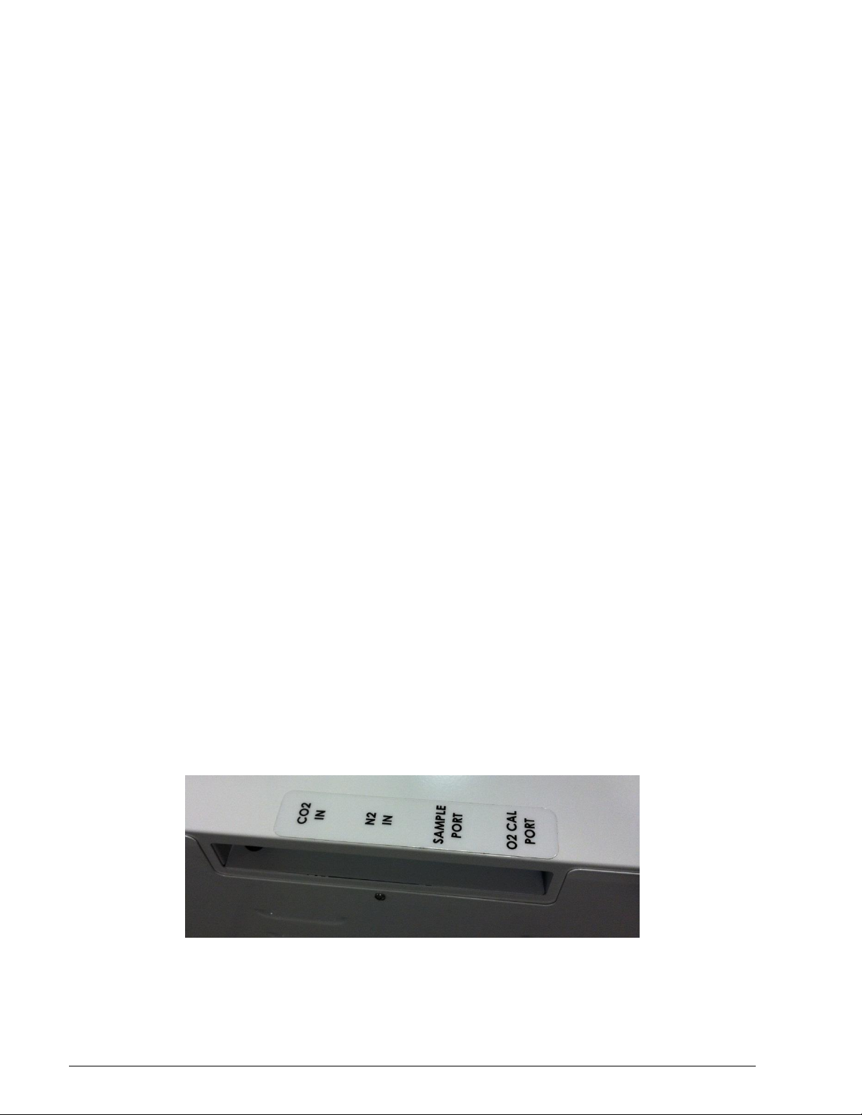
5.4 Hose ports for the gas are provided on the upper left side of the unit. The Bactrox chamber has
five access ports on the left side of the unit. See Diagrams Section page 33 (INTERIOR
PLUMBING) for more details.
5.5 Install one end of the hose from the N2 gas regulator of the gas tank to the port marked “N2
PORT” on the plumbing connections panel.
5.6 Install one end of the hose from the CO2 gas regulator of the gas tank to the port marked “CO2
PORT” on then plumbing connections panel.
NOTE: CONNECTING HOSES. Hose connections are intended to be simple. Insert the hose into
the barb until the hose stops.
5.7 Plug power cord from Bactrox into a suitable outlet. Refer to the Installation Section of this
manual for additional information. Turn the power switch ON to verify power to the system.
5.8 When the power switch to the Hypoxic Chamber is activated, you should see a light in the backlit power switch, the O2 and CO2 digital display panels illuminate, along with a readout of the
incubator temperature. If any of these appear not to work, consult the Troubleshooting Guide.
6. THERMOELECTRIC CONDENSATE CONTROLER
6.1 The thermoelectric condensate controller collects excess humidity and eliminates chamber
condensation. Moisture is funneled into a tube for collection inside your chamber.
6.2 The thermoelectric condensate controller is located on the left side of the chamber interior
behind circulation fan. A plastic tube drains excess moisture into the working chamber, on the
back left side.
6.3 Place a container, e.g., glass flask or beaker, under the tube for collection. Empty the container
DAILY.
6.4 Desiccants are not recommended in the chamber. Desiccants are drying agents that will pull
moisture from your samples by removing humidity and leaving condensate.
7. INCUBATOR TEMPERATURE CONTROLLER/SET OVER
TEMPERATURE
Under certain circumstances, samples placed directly on the bottom shelf may become too hot and dry out. Shelf
spacers are provided to minimize this condition. Three spacers are provided for the BACTROX. Place these
spacers on the bottom shelf. Note the slots go to the front and back.
7.1 Setting Incubator Controller: The incubator temperature controller regulates the incubator
temperature by use of Up/Down buttons. To enter set point mode on the control, press either the
Up or Down button one time. The digital display will start to blink, going from bright to dim. While
blinking, the Digital Display is showing the set point. To change the set point, use the Up and
Down buttons. If the buttons are not pressed for five (5) seconds, the display will stop blinking
and will read the temperature of the unit. Note that the SET OVER TERMPERATURE knob
should be turned to its maximum position, (clockwise) until the unit has stabilized at desired set
Bactrox Operations Manual 9
Page 10

__________________________________________________________________________
point temperature. Allow the incubator at least 24 hours to stabilize. Then re-calibrate the digital
display to your reference thermometer, follow the calibration instructions. This incubator was
calibrated at the factory at 370C.
7.2 Setting Incubator Safety: First, set the control to the desired incubator temperature and then the
INCUBATOR SAFETY to its maximum position. Allow 24 hours for stabilization before
proceeding.
7.3 If, after 24 hours the temperature is not at desired level, adjust the SET TEMPERATURE up or
down using the arrows until the precise desired temperature is achieved.
7.4 When stabilization at the desired temperature has been achieved, turn the SET OVER
TERMPERATURE control knob counter-clockwise until the OVER TEMP ACTIVATED light
comes on and audible alarm is activated. Next, carefully turn the SET OVER TERMPERATURE
knob clockwise until the light is just off. The safety is now set; the OVER TEMP ACTIVATED
light should remain OFF during normal operation.
7.5 NOTE: An accurate thermometer should be used inside the incubator as a reference when
setting and calibrating the incubator temperature.
7.6 It is a good idea to mark the SET OVER TERMPERATURE label with the desired setting or
position as a backup in case the knob is moved accidentally. If the OVER TEMP ACTIVATED
light is on and audio alarm is activated at any time, check the SET TEMPERATURE controller
setting to be sure that it is not set above the SET OVER TERMPERATURE setting.
7.7 Alarm Controls and Display: The temperature control, O2, and the CO2 control are both
equipped with visual and audible alarms.
• Temperature Alarms: The temperature control has alarm indicators for high and low conditions
that are activated whenever the actual temperature is 1°C above or below the set point.
• O
Alarms: The O2 controller has alarm indicators for high and low alarm conditions that are
2
activated whenever the actual O2% is 1% above or below the set point.
• CO2 Alarms: The CO2 controller has alarm indicators for high and low alarm conditions that are
activated whenever the actual CO2% is 1% above or below the set point.
• Audible Alarms: Both controls have audible alarms that are activated when either of the HIGH
or LOW indicators is activated.
7.8 Muting Audible Alarms: The audible alarms can be muted for a single alarm occurrence by
pressing and holding down EITHER the UP or DOWN button for several seconds until the alarm
mutes. There is a built in delay of approximately 15 minutes on the occurrence of a LOW alarm.
This time delay prevents the audible alarm from activating every time the door is opened and the
temperature and CO2 drops.
8. CO2 CONTROL CALIBRATION
8.1 Manufacturer’s Recommendation for Monitoring CO2 Levels: CO2 sensors are factory calibrated
and, under normal circumstances, need no calibration. It is recommended that the accuracy of
your CO2 control system be monitored by measuring the actual CO2 concentration on a weekly
basis with a Fyrite or other measuring device. This should be done when the chamber has not
been opened for an extended period of time, i.e. after the weekend, and should only take 1-2
hours.
8.2 Setting the CO2 Control: Attach the supply hose from the CO2 tank to the Bactrox CO2 inlet fitting
and turn on the CO2 supply. Set the CO2 control to the desired set point using the up and down
arrows. The CO2 level comes from the factory preset to OFF.
8.3 Adjusting CO2 Display: After the Bactrox has had several hours to stabilize at the desired CO
set point and measure the actual CO2% with a Fyrite gas analyzer. If there is any difference
between the Fyrite gas analyzer and the display, use the procedure described in section 7 page
14 for calibrating CO2. See Section 9 Page 19 (next page) for Fyrite use and instruction.
NOTE: When using the Fyrite gas analyzer, insure that gas is not being injected while the reading is
being taken. Always change the CO2 set point to 0.0 prior to taking the sample and change the set point
back to the desired value after the use of the Fyrite gas analyzer is finished.
8.4 Using a FYRITE to Measure CO2 Levels
A Bacharach FYRITE CO2 Gas Analyzer is recommended to measure CO
concentrations in the Bactrox chamber. This test instrument is not supplied with the
2
2
Bactrox Operations Manual 10
Page 11

__________________________________________________________________________
Bactrox but is readily available from your dealer. Follow the instructions provided with
each Fyrite instrument carefully to ensure correct and accurate readings.
Fyrite Quick Overview
Press button on top of Fyrite canister to release CO2 concentration. RELEASE BUTTON
and tip canister to the side to ensure all fluid is released from the top of the canister.
Return canister to the upright position.
Loosen screw on slide scale and align top of fluid with zero on the scale. Tighten screw.
Connect hose and aspirator bulb to unit being tested. The sample port for connection is
located on the control panel.
Place the hose sampling cap directly over the plunger valve on top of the canister and
depress firmly.
With button depressed, squeeze bulb 20 times. On the last squeeze and with bulb still
deflated, release hose from button.
Turn Fyrite canister upside down 3 times, each time allowing all fluid to flow to the
opposite end of the canister.
Tilt canister to the 45 degree position to ensure all fluid has been released from top of
canister. Return canister to the upright position.
Read CO2 concentration in %.
WARNING: The fluid used inside this fyrite instrument is poisonous and corrosive. If taken internally
could result in serious injury or death. The fyrite indicator will come with a complete set of detailed
instructions which should be followed carefully. In the event of a spill or accidental body contact with the
fyrite fluid, follow the instructions on the refill bottle carefully.
9. OXYGEN CONTROL CALIBRATION
9.1 There are two recommended methods of calibration, depending on equipment availability and
the accuracy required over a wide range of percent Oxygen. Calibration is done using room air
(20.7% O2 is an average value based on the humidity and partial pressure of O2 in the
atmosphere. This value should be calculated for your present environmental conditions.) and a
tank of certified tank of oxygen and nitrogen mixture. An example would be a dry 5% oxygen
and 95% nitrogen mixture.
9.2 Offset calibration can be done through front panel display buttons. See the OFFSET Calibration
section below.
9.3 To complete a two point linear calibration the Bactrox needs to be hooked up to a computer that
has RS-232 capability with windows terminal or internet access to download TERATERM off the
web. Calibration should be done before chamber use.
9.4 To calibrate first install the calibration cover onto sensor box in figure 1, using the two screws
provided.
Figure 8
Bactrox Operations Manual 11
Page 12

__________________________________________________________________________
9.5 TWO POINT CALIBRATION PROCEDURE
9.5.1 The two point calibration procedure requires a terminal emulator program. Shel Lab
recommends the free, open source emulator Tera Term.
9.5.2 Tera Term can be downloaded for free from the developer’s project page
http://ttssh2.sourceforge.jp/index.html.en. Follow the instructions to download and
install the emulator.
9.5.3 Once the software has been installed hook up the RS232 DB9 cable to the back of
the oxygen controller. If the computer has a RS232 port, plug the other end of the
DB9 cable to the RS232 port. If the computer has only USB use the USB to RS232
adaptor provided with the calibration kit.
9.5.4 The oxygen concentration in the chamber will fluctuate during the calibration
procedure. Sensitive items should be removed or placed in sealed containers if
varying levels of O2 will have a negative impact.
9.5.5 Turn on the Bactrox and allow 5 minutes for the oxygen sensor to warm up. The
oxygen sensor needs to warm up before it can start reading oxygen levels
accurately.
9.5.6 Turn on the computer and open the TERATERM software and click the serial button
in the pop up window and click OK.
9.5.7 The controller should start logging once every minute. If it does not log, close
TERATERM and reopen it again but, before clicking okay try another com port.
Once the control starts to log into TERATERM, communication has been
established.
9.5.8 If you would like to save the oxygen readings to a log file. Click on the File tab. Then
the Log tab. Then create a filename to save your data in. Click OK. Data will now be
saved into that file as reading is taken.
9.5.9 Plug in the Oxygen Calibration Pump into an electrical outlet and press the power
button to turn on the pump. Hook up the hose to the calibration port on the left hand
corner of the unit.
9.5.10 Set the O2 set point to OFF. Push the Set Oxygen% down arrow and release. When
the green Oxygen % display starts flashing, push and hold down the down arrow
until the display reads “OFF”. Let the control stabilize at atmosphere for at least 5
minutes.
9.5.11 Before a calibration can be completed you must type BRO2=0. Setting this value to
“0” will allow the controller to be accessed and calibrated.
9.5.12 Before a two point calibration is performed the offset calibration must be set to 0. To
view the current offset type OC2 and press enter. To set the offset calibration to zero
subtract the offset value from the current display reading (if it is a positive number),
then type in OC2= (the result of display-offset). If the offset calibration value is a
negative number then add the absolute value back to the current display reading
OC2=(the result of display –offset). Check that the Offset value is truly zero by
typing “OC2” and “enter”. If the readout then displays OC2=0, then proceed to the
next step.
9.5.13 If the display does not read 20.7 percent oxygen concentration then an upper
calibration should be entered.
9.5.14 To enter an upper calibration type in UC2=20.7 in uppercase in the TERATERM
program. The TeraTerm window will display UC02=20.7. The digital “SET O2%”
display should now read 20.7 percent oxygen. Remove the Calibration pump tubing
from the calibration port.
9.5.15 Hook up the certified calibration gas to the calibration port and turn the gas on with
the regulator set no higher than 3 PSI. Allow the control and sensor to stabilize for at
least 5 minutes.
9.5.16 If the display does not match to what the certified calibration gas states then a low
calibration needs to be entered.
Bactrox Operations Manual 12
Page 13

__________________________________________________________________________
9.5.17 To enter a low calibration, type in LC2= (value of certified calibration gas) in
uppercase in the TERATERM program. The display will show LC2=( value of
certified calibration gas)
9.5.18 Unhook the calibration gas and reconnect the Calibration O2 pump box again and
allow at least 5 minutes for the sensor to stabilize. This will show the curve is still
accurate over the full range.
9.5.19 The display should return to 20.7 percent. Remove the tubing from the calibration
port barb. Replace the barb plug/cap.
9.5.20 Remove calibration cover. Two point calibrations are now complete.
9.5.21 Set the main “SET OXYGEN %” display to the desired setpoint via the up and down
arrows. Allow the reading to stabilize before use.
9.6 OFFSET CALIBRATION PROCEDURE
9.6.1 The second method of calibration does not require a computer. It requires a
calibration gas selected to match the process the chamber is going to be used.
Offset calibration is a single point calibration and should only be used in applications
where having an absolute linear curve throughout the O2 range is not an issue.
Users should obtain calibration gas at a concentration that matches the value where
the chamber is going to be operated.
9.6.2 To calibrate install the calibration plate. FIGURE 1.
9.6.3 Hookup the calibration gas to calibration port FIGURE 2.
9.6.4 Turn the calibration gas on with the regulator set no more than 3 PSI.
9.6.5 Allow the control to stabilize for at least 5 minutes.
9.6.6 If display does not match what the certified calibration gas states then an offset
calibration needs to be entered.
9.6.7 To enter the offset calibration push and hold both up and down arrow simultaneously
until “CO” flashes and then the current display value flashes then release the
buttons.
9.6.8 While the current display value is flashing, use the up or down arrow to change the
value in the display to match the calibration gas.
9.6.9 After the value is entered the display will stop flashing after 5 seconds if no buttons
are pushed returning to normal operation. The display should now match the
calibration gas.
9.6.10 Remove the calibration gas and calibration cover. It is important to note that a single
point calibration may cause O2 readings outside of the calibration gas to be incorrect.
10. POWER ON THE BACTROX:
10.1 Check power supply against unit plate and make sure they match. Be certain that the fuse is
installed in the power inlet of the unit. Start by attaching the cordset (supplied with the
accessories) to the unit inlet and the building power supply. Attach the female end of the cordset
into the fused and recessed male plug on the rear of the unit and the male plug end of the
cordset into the building supply receptacle.
10.2 Check that the appropriate plumbing connections have been made for N2 and CO2 supply.
10.3 Turn the power switch to the I/ON position. Operating temperature must be set, achieved and
calibrated before C02 connection and adjustments are made. Set the C02 control setpoint to
OFF. To do this, press and release the down arrow Button. The display will flash “SP” and then a
number. While the number is flashing, press the down arrow button and hold it down until the
display is flashing “OFF”, then release the button. Then press the down arrow until the CO2
setpoint is “OFF”.
10.4 Muting Audible Alarms: Powering the unit on prior to calibration may activate the built in alarm
system. To mute the alarm hold EITHER the up or down button until the “mute” indicator
activates.
Bactrox Operations Manual 13
Page 14

__________________________________________________________________________
10.5 Initial Control Settings: Each Bactrox comes preset from the factory at 37C and the O2 and
CO2 set to off. You should allow the incubator to heat up and stabilize for 24hrs. Turn the SET
OVERTEMPERATURE control clockwise until it stops so that it does not activate during the
initial warm up.
10.6 Calibrating the Controls for Temperature or CO2:
10.6.1 Push and hold BOTH the UP and DOWN buttons simultaneously for five (5) seconds.
10.6.2 If you are calibrating temperature, the Temperature Display panel will read “CO” and
then blink.
10.6.3 If you are calibrating CO2 Level, the CO2 will read “CO” and then blink.
10.6.4 While the display is blinking use the UP and DOWN buttons to adjust the display to
match the actual condition in the incubator chamber.
10.6.5 If no buttons are pressed within five (5) seconds the blinking will stop and the display will
revert to showing the process or actual parameter within the incubator chamber.
11. MAKING THE CHAMBER HYPOXIC
11.1 Prior to Purging the Chamber: Turn Power switch to the “O” (Off) position.
11.2 Connect Nitrogen and Carbon Dioxide Gas supplies as directed in the Bactrox Appendix.
11.3 Open the incubator doors before leaving the chamber. This allows the incubator to become
hypoxic at the same rate as the workspace.
11.4 Put arm port doors in place, or the Arm Port Sleeve Plugs
NOTE: The Bactrox chambers have an efficient method for sealing the chamber by utilizing the Arm port
doors as shown in Figure 3. The tightening knob on the Arm port doors should be snug, DO NOT OVER
TIGHTEN. Damage can occur if too much force is placed on the Arm port door assembly. When the
knob just begins to “grab”, the tightening bolt has reached its maximum point. Over tightening will cause
the bolt to slip inside the handle and cause leakage.
Purging the Chamber
11.5 Turn Power Switch to the “I” (On) position on the Control Module.
11.6 Note the reading on the gas regulators.
11.7 Set the Oxygen Setpoint to the desired value using the up and down arrows.
11.8 Set the Carbon Dioxide Setpoint to the desired value using the up and down arrows.
11.9 The Oxygen controller will automatically add Nitrogen gas or ambient air to achieve the desired
setting. Normally, it takes 1-1/2 to 2 hours to achieve a 1% concentration of O2 inside the
chamber workspace, after initialization from ambient air.
11.10 The CO2 control module will automatically add Carbon Dioxide gas or Nitrogen to achieve the
desired setting. Normally, it takes ~45 minutes to achieve a 1% concentration of CO2 inside the
chamber workspace, after initialization from ambient air.
11.11 If a precise control of the O2 concentration is required, refer to the calibration section of this
manual, to enter a custom calibration. The O2 module is calibrated at the factory for two point
curve at 1% and 20.7%.
Summary
The chamber is ready when:
The “SET OXYGEN %” led display reads the desired concentration of oxygen.
The “SET CO 2%” led displays reads the desired concentration of oxygen.
The “SET TEMPERATURE” controller displays the desired value. NOTE: It may take several
hours to overnight to achieve temperature stability after the incubator doors are closed after
initialization.
12. PASS BOX OPERATION
12.1 Load the PASS BOX with samples, materials, supplies, etc.
12.2 Close the outer and inner PASS BOX Doors.
12.3 Activate the PASS BOX
Bactrox Operations Manual 14
Page 15

__________________________________________________________________________
12.3.1 Locate the “START PASS BOX PURGE” switch which should be in the bottom OFF
position.
NOTE: Do not hold Auto Cycle Start Switch down. Simply press the button and let go to
activate.
12.3.2 Press the “START PASS BOX PURGE” switch once to initiate the cycle. The PASS
BOX will purge nitrogen thru the PASS BOX for 45 seconds. The PASS BOX
PURGING light will alternately flash on and off, indicating the cycle is in progress. When
the cycle is complete, the system will stop automatically and the PASS BOX PURGING
light will turn off. This light will NOT remain on after a cycle is complete.
12.3.3 If the cycle does not follow the sequences in the previous section on consult the
Troubleshooting Guide for adjustments. NOTE: Do not hold “START PASS BOX
PURGE” switch down. Simply Press the button and let go to activate.
12.3.4 If you want to abort the cycle, press and hold the “START PASS BOX PURGE” switch
for 5 seconds. Then the “PASS BOX PURGING” pilot light will stop flashing.
13. ENTERING THE CHAMBER
13.1 The rubber cuffs of the sleeve should be secured around your arm as opposed to clothing.
Remove sharp objects such as rings, watches, bracelets, etc., as they may damage the cuffs.
13.2 Insert your hands and forearms into the sleeves. The cuffs must be firmly secured around your
bare forearms.
13.3 Loosen the arm port door knobs a few turns by turning the black wing nut counterclockwise, and
rotate the locking bars to a horizontal position. The arm port doors can now be pushed forward
into the chamber interior and can be secured on the arm port door holders.
NOTE: Arm movements that are too forceful may cause the sleeves to dislodge from the arm ports.
14. EXITING THE CHAMBER
14.1 Doors are used to seal the Arm ports while the chamber is not in use. Doors can be stored
using the holders provided while the chamber is in use. Assembly consists of an Arm port door,
tightening knob and locking bar. Doors are secured by turning the locking bars horizontally to
pass through the cutouts in chamber, then turning locking bars vertical and tightening the knobs.
14.2 Before leaving the chamber the incubator doors and the inner PASS BOX door must be closed.
14.3 Hold the locking bars in a horizontal position, and close the doors. Rotate the locking bars to a
vertical position, and gently tighten the black wing nut on both arm port door knobs, just until
they “grab”.
14.4 When the arm port doors are properly sealed, slowly and carefully withdraw both arms from the
sleeves.
15. MAINTENANCE
15.1 DAILY/ROUTINELY: Before using any cleaning or decontamination method except those
recommended by the manufacturer, users should check with the manufacturer that the proposed
method will not damage the equipment.
15.2 Remove and/or empty condensate collection container.
15.3 Disinfect the chamber interior. Do not use any volatile cleaning compounds such as alcohol,
bleach or volatile ammonium based cleaners as these compounds will create a toxic
environment for the growth of the microorganisms. Do not use alcohol based cleaning products
on the Plexiglas.
15.4 Check the cuffs on the sleeve system. If the cuffs have holes or any tears, replace.
15.5 Check incubator temperature.
15.6 Record gas tank readings.
15.7 Change/Rejuvenate Anatox. Anatox absorbs volatile fatty acids and hydrogen sulfide in the
chamber. Recommended use is 250 grams placed in a beaker in the chamber.
Anatox-1000 grams (packaged in 250 gram packages)
Instructions:
Empty two (2) 250 gram packages into two (2) separate 500 ml Pyrex beakers.
Day one – place one beaker in the chamber (new Anatox can be placed directly into the
chamber).
Bactrox Operations Manual 15
Page 16

__________________________________________________________________________
Tank Switch
Chamber Stand
Switches and monitors dual gas tank supply. Provides
automatic switch-over to second gas tank alarm
sounds when both tanks are empty. Tanks can be
switched manually at any time.
Provides work bench to support Bactrox chambers.
Chamber Stand height 30”. Stands feature locking
casters and storage space.
Model # 2002-B
Nitrogen Gas Regulator
CO2 Gas Regulator
Optional accessory used in a two gas chamber
Part # 7150500
Optional accessory used in a two gas chamber
Part # 7150500
Cleaner
Plexiglas Cleaner
Benzalkonium Chloride
#1060503-8 oz size
Plexiglas Scratch Remover
#1060504-8 oz size
ACCESSORIES PARTS LIST
Catalog No.
Product
5110729
Petri-Plate Rack 2x13
9990738S
9990738M
9990738L
Sleeves, Complete
Small
Medium
Large
9490507
UV Light Source
9490512
Start Up Kit
3600500
Rubber Cuffs, Sm Size 7
3600501
Rubber Cuffs, Med Size 8
3600502
Rubber Cuffs, Lrg Size 9
6000501
O-Ring For Door
6000504
O-Ring For Cuff
3450506
Gasket-Airlock
3600513
Nitrile Gloves-Size 7
3600514
Nitrile Gloves-Size 8
3600515
Nitrile Gloves-Size 9
3600525
Nitrile Cuffs-Size 7
3600526
Nitrile Cuffs-Size 8
3600527
Nitrile Cuffs-Size 9
7200502
Rubber Cuff Plugs
Day two – remove beaker in the chamber and replace with the second beaker of Anatox
(also new).
Day three – reactivate the first beaker of Anatox by heating at 160C for 2 hours. Then
replace the beaker in the chamber with this reactivated beaker.
Day four – six months – continue switching the reactivated beakers daily until six
months is complete, then discard the old Anatox and repeat the procedure again.
16. ACCESSORIES
Bactrox Operations Manual 16
Page 17

__________________________________________________________________________
Problem
Possible Cause
Solution
PASS BOX Purge will not start.
A. Input/output terminal buss is not
seated correctly.
A. Press down on the terminal buss
so that it snaps into place.
NOTE: Power should be turned off.
B. User pushed start switch and
held inadvertently held down.
Thus aborting Auto Cycle.
B. Push start switch once then
release.
D. Start button inoperative -
D. Replace start button.
E. No power to controller - check
power light on Controller.
E1. Check for 24 volt DC out of
power supply.
E2. Check for continuity between
power supply and controller.
Problem
Possible Cause
Solution
Steady digital readout matches
set point, but actual temperature
does not.
A. Temperature Controller out of
calibration.
A. Follow Complete Temperature
Controller instruction.
B. Incubator door open.
B. Close incubator door and
allow incubator to stabilize.
Digital readout and actual
temperature continue to increase
past set point.
A. Output relay stuck - Check to
see if" Incubator Heating"
Indicator light stays on while
temperature is Increasing.
A. Replace Temperature
Controller.
B. Incubator door open.
B. Close incubator door and
allow incubator to stabilize.
Audible alarm sounds.
A. Temperature has risen beyond
the set range for the High
Limit Safety.
A. Determine cause of
temperature increase from
prior section and take
appropriate action.
Call for service.
Problem
Possible Cause
Solution
Role of Condensate Controller:
The Condensate Controller is an
exclusive Bactrox feature of
Sheldon Manufacturing, Inc. Our
competitors use desiccants.
Desiccants are a drying agent
and often dry out samples.
CAUTION: Extreme caution must be exercised any time access is made into areas housing
electrical components. Repair, replacement or adjustment of components in these areas must
only be done by qualified technicians familiar with electrical circuitry and the operation of the
hypoxic chamber.
ATTENTION: Des Précautions extrèmes sont requises à chaque fois que vous accédez à des
endroits qui abritent les composantes électriques. La réparation, le remplacement oi
ìajustement de composanted dans ces endroits ne doivent être effectués que par un technicien
qualifié familier avec les circuits électriques et ì opération des étuves anaérobiques.
17. TROUBLESHOOTING
I. PASS BOX
II. INCUBATOR
III. MISCELLANEOUS
Bactrox Operations Manual 17
Page 18

__________________________________________________________________________
Problem
Possible Cause
Solution
Amount of Water Collected in the
Dehumidifier:
The amount of water collected in
the dehumidifier depends on the
number and types of samples in
the chamber. The typical amount
collected is around 50 cc each
day of chamber use.
Excessive moisture buildup in
chamber.
A. Thermoelectric condensate
controller fan is not
operating.
A. Replace fan.
B. Ambient room temperature
too low.
B1. Maintain room temperature a
bit higher.
B2. Cover chamber with a blanket
overnight as means of
installation.
C. Air conditioner unit directly
above chamber.
C. Relocate chamber, redirect
the air conditioning duct.
D. Thermoelectric condensate
controller not emptied
regularly.
D. Empty thermoelectric
condensate controller
container.
Bactrox Operations Manual 18
Page 19

__________________________________________________________________________
Gas Source:
Sheldon Manufacturing, Inc. recommends an two separate tanks of 100% CO, ,
and 100% Nitrogen for Hypoxic applications.
These mixtures are available marked “NON-FLAMMABLE”.
Two national sources of gas are AIRGAS, PRAXAIR, and Air Liquid.
How much gas will a
Bactrox chamber use?
Gas usage is dependent upon three things; the number of times a user
enters their chamber daily, operating technique, and the number of PASS
BOX purge cycles.
Our product literature states the PASS BOX uses approximately 45
seconds of gas to purge the oxygen to appropriate hypoxic levels.
Methods to Conserve Gas:
Users can utilize the PASS BOX as a holding station. As samples are
received they can be stored in a hypoxic environment by placing them in
the PASS BOX and activating either the automatic or manual PASS BOX
cycle.
1. Users should evaluate and try to limit the number of times the PASS
BOX is cycled. For example, placing samples in the PASS BOX
once in the morning and once in the afternoon as opposed to four
times a day is desirable.
2. Gas is also conserved by bringing samples in through the sleeve
system. Easy samples to transport through the sleeves are transport
tubes as well as plates that are sealed.
3. Good sleeve system technique.
When a user is in the “Working Area” they should be aware of the
effects their movements have on gas consumption.
Gas consumption can be reduced by balancing arm movements.
For example, when extending the right arm into the chamber, bring
the left arm close to the front of the chamber, thus balancing the
pressure and reducing gas displaced by area.
Aborting PASS BOX PURGE
CYCLE:
The automatic PASS BOX can be aborted by pressing and holding the
“START PASS BOX PURGE” button for five (5) seconds. If a user forgets
to place a sample in the PASS BOX the cycle can be aborted in order to
eliminate the unnecessary use of gas.
Chamber Checklist:
It is recommended that customers review a checklist before they enter the
Bactrox Chamber. The checklist serves as a reminder of supplies and
samples they need to bring into the unit.
Common items listed on a checklist are: re-activated anatox, samples and
loops. The checklist can be placed on the front Plexiglas panel.
Size of Sleeve Cuffs:
It is critical that the sleeve cuffs seal around the user’s arm during chamber
operation to ensure the desired hypoxic environment.
The location that the cuffs seal on the user’s arm is determined by
individual preference.
The size of the cuffs that come standard with the Bactrox Chamber is
medium, size 8 glove. Other sizes are available; large size 9, and small
size 6 ½.
Replacement of Cuffs:
When and how often the cuffs on the sleeve need to be replaced depends
on customer care and technique. Typically the cuffs are replaced about
every three months.
Customers should watch for small holes that can appear where the cuffs
are placed on the “ring cuff”. If holes are present the cuffs should be
replaced to avoid gas leak. Watches and jewelry can damage the cuffs
and are not recommended to be worn during chamber use.
18. BACTROX OPERATION TIPS
Bactrox Operations Manual 19
Page 20

__________________________________________________________________________
Model Number
Interior
Dimensions
W x D x H
(Inches)
Exterior
Dimensions
W x D x H
(Inches)
Chamber
Capacity
Shipping
Weight
Unit
Weight
BACTROX,
BACTROX-2
48.5 x 31.0 x 32.6
300 plates
Model Number
Temperature Range
(Control)
Temperature
Uniformity
O2 Range
CO2 Range
BACTROX,
BACTROX-2
Ambient + 8 to 60C
(+/- 0.1C)
+/- 0.35C @ 37C
0-20%
0-20%
Model
Volts
Amps
VA
Cycles
BACTROX
120
3.5
1100
50/60 hz
BACTROX-2
240 2 1100
50/60 hz
19. UNIT SPECIFICATIONS
Electrical
Bactrox Operations Manual 20
Page 21

__________________________________________________________________________
4 LOOP CONTROL
BOARD SL# 1750972
J8
MAIN TEMP
SENSOR
CO2
SENSOR
J17
02
SENSOR
J16
BUSS
LOAD 1
LOAD 3
LOAD 4
J1
J2
J3
J4
J6
J7
EARTH GRD
(NEUT)
(HOT)
J10
COMMUNICATION
ALARM
CONTACTS
TO DB9
CONNECTOR
TEMPERATURE
SENSOR
J12
BLACK 22G
BROWN 22G
PURGE
TIMER
8250513
120V230V COM
OTP
CONTROL
1750500
2
34
1
SOLID STATE
RELAY
7030533
O2 DISPLAY
1750974
CO2 DISPLAY
1750975
TEMP DISPLAY
1750973
LED LIGHT BAR 4650547
TTB2#4
TTB2#3
TTB2#2
TTB1#9
TTB1#12
TTB1#11
TTB1#10
TTB1#5
TTB1#7
TTB1#8
TTB1#6
TTB1#4
TTB1#3
TTB1#2
TTB1#1
TTB1#13
TTB1#14
BLACK 22G
RED 22G
BROWN 22G
WHITE 22G
BLACK 22G
RED 22G
RED 18G
BLACK 18G
HEAT LIGHT
4650554
OTP LIGHT
4650553
AIR LIGHT 4650554
CO2 LIGHT 4650554
N2 LIGHT 4650554
PURGE LIGHT 4650550
RED 18G
BLACK 18G
BLACK 18G
RED 18G
RED 18G
BLACK 18G
TB1#1
TB2#9
TB1#3
TB2#8
TB1#4
TB2#10
TB1#5
TB2#7
TB1#6
TB2#12
TB1#2
TB7#18
TB7#13
TB8#20
TB8#19
TB7#16
TB8#21
TB7#14
TB7#15
TB4#19
TB4#21
TB4#23
TB4#22
TB4#20
TB5#6
TB5#1
TB6#12
TB6#7
TB6#8
TB6#9
TB6#10
BLACK 14G
BLACK 14G
BLACK 14G
BLACK 14G
BLACK 14G
BLACK 14G
BLACK 14G
BLACK 18G
BLACK 18G
WHITE 18G
WHITE 18G
WHITE 14G
WHITE 14G
WHITE 14G
WHITE 14G
WHITE 14G
WHITE 14G
WHITE 14G
WHITE 14G
WHITE 14G
WHITE 14G
WHITE 14G
WHITE 14G
WHITE 14G
WHITE 14G
WHITE 14G
WHITE 14G
WHITE HT 14G
BLACK 14G
CHAMBER FAN
4880550
AIR
PUMP
AIR PUMP
6700558
60W 120V
2350502
60W 120V
CO2 N2PURGE
SOLENOID
VALVES
8600528
CO2 IR SENSOR
8320510
THERMOELECTRIC
CHILLER
1070502
24VDC
POWER
SUPPLY
6750516
12VDC
POWER
SUPPLY
6750514
O2 SST SENSOR
6600532
GREEN LIGHTED POWER SWITCH 7850570
LIGHT SWITCH
7850579
RED 18G
BLACK 18G
RED 18G
RED 18G
BLACK 18G
BLACK 18G
RED 24G
RED 24G
BLACK 24G
BLACK 24G
GREY 14G
GREY 14G
RED 14G
RED 14G
RED HT 14G
RED 14G
ORANGE 14G
BLUE 14G
BLUE 14G
YELLOW 14G
YELLOW 14G
BROWN 14G
BROWN 14G
YELLOW 14G
BLUE 14G
BROWN 14G
SENSOR
8100500
BLACK 14G
WHITE 14G
INLET
4200505
EMI FILTER
2800502
OUTLET
6100529
TB6#11
TB8#24
1
2
3
TTB1#16
TTB1#15
BROWN 22G
WHITE 22G
PURGE SWITCH
7850531
BROWN 22G
WHITE 22G
80K OHMS
6
4
5
DIAGRAMS
WIRING DIAGRAM BACTROX (9851358)
Bactrox Operations Manual 21
Page 22

__________________________________________________________________________
4 LOOP CONTROL
BOARD SL# 1750972
J8
MAIN TEMP
SENSOR
CO2
SENSOR
J17
02
SENSOR
J16
BUSS
LOAD 1
LOAD 3
LOAD 4
J1
J2
J3
J4
J6
J7
EARTH GRD
(NEUT)
(HOT)
J10
COMMUNICATION
ALARM
CONTACTS
TO DB9
CONNECTOR
TEMPERATURE
SENSOR
J12
BLACK 22G
BROWN 22G
PURGE
TIMER
8250510
1
2
3
120V230V COM
OTP
CONTROL
1750500
2
34
1
SOLID STATE
RELAY
7030533
O2 DISPLAY
1750974
CO2 DISPLAY
1750975
TEMP DISPLAY
1750973
LED LIGHT BAR 4650547
TTB2#4
TTB2#3
TTB2#2
TTB1#9
TTB1#12
TTB1#11
TTB1#10
TTB1#5
TTB1#7
TTB1#8
TTB1#6
TTB1#4
TTB1#3
TTB1#2
TTB1#1
TTB1#16
TTB1#15
TTB1#13
TTB1#14
BLACK 22G
RED 22G
BROWN 22G
WHITE 22G
BLACK 22G
RED 22G
RED 18G
BLACK 18G
HEAT LIGHT
4650554
OTP LIGHT
4650553
AIR LIGHT 4650554
CO2 LIGHT 4650554
N2 LIGHT 4650554
PURGE LIGHT 4650550
RED 18G
BLACK 18G
BLACK 18G
RED 18G
RED 18G
BLACK 18G
BROWN 22G
WHITE 22G
TB1#1
TB2#9
TB1#3
TB2#8
TB1#4
TB2#10
TB1#5
TB2#7
TB1#6
TB2#12
TB1#2
TB7#18
TB7#13
TB8#20
TB8#19
TB7#16
TB8#21
TB7#14
TB7#15
TB4#19
TB4#21
TB4#23
TB4#22
TB4#20
TB5#6
TB5#1
TB6#12
TB6#7
TB6#8
TB6#9
TB6#10
BLACK 14G
BLACK 14G
BLACK 14G
BLACK 14G
BLACK 14G
BLACK 14G
BLACK 14G
BLACK 18G
BLACK 18G
WHITE 18G
WHITE 18G
WHITE 14G
WHITE 14G
WHITE 14G
WHITE 14G
WHITE 14G
WHITE 14G
WHITE 14G
WHITE 14G
WHITE 14G
WHITE 14G
WHITE 14G
WHITE 14G
WHITE 14G
WHITE 14G
WHITE 14G
WHITE 14G
WHITE HT 14G
BLACK 14G
CHAMBER FAN
4880551
AIR
PUMP
AIR PUMP
6700559
60W 120V
2350502
60W 120V
CO2 N2PURGE
SOLENOID
VALVES
8600529
CO2 IR SENSOR
8320510
THERMOELECTRIC
CHILLER
1070502
24VDC
POWER
SUPPLY
6750516
12VDC
POWER
SUPPLY
6750514
O2 SST SENSOR
6600532
GREEN LIGHTED POWER SWITCH 7850570
PURGE SWITCH
7850531
LIGHT SWITCH
7850579
RED 18G
BLACK 18G
BROWN 22G
WHITE 22G
RED 18G
RED 18G
BLACK 18G
BLACK 18G
RED 24G
RED 24G
BLACK 24G
BLACK 24G
GREY 14G
GREY 14G
RED 14G
RED 14G
RED HT 14G
RED 14G
ORANGE 14G
BLUE 14G
BLUE 14G
YELLOW 14G
YELLOW 14G
BROWN 14G
BROWN 14G
YELLOW 14G
BLUE 14G
BROWN 14G
SENSOR
8100500
80K OHMS
BLACK 14G
WHITE 14G
INLET
4200505
EMI FILTER
2800502
OUTLET
6100531
WHITE 14G
TB6#11
TB8#24
6
4
5
WIRING DIAGRAM BACTROX-2 (9851363)
Bactrox Operations Manual 22
Page 23

__________________________________________________________________________
4 LOOP CONTROL
BOARD SL# 1750972
J8
MAIN TEMP
SENSOR
CO2
SENSOR
J17
02
SENSOR
J16
BUSS
LOAD 1
LOAD 3
LOAD 4
J1
J2
J3
J4
J6
J7
EARTH GRD
(NEUT)
(HOT)
J10
COMMUNICATION
ALARM
CONTACTS
TO DB9
CONNECTOR
TO TEMP
DISPLAY
BUSS CONNECTION
TEMPERATURE
SENSOR
TTB1-1
TTB1-2
TTB1-3
TTB1-4
TTB1-5
TTB1-6
TTB1-7
TTB1-8
TTB1-9
TTB1-10
TTB1-11
TTB1-12
TTB1-13
TTB1-14
TTB1-15
TTB1-16
TB5-1
TB6-7
TB6-8
TB6-9
TB6-10
TB7-13
TB7-14
TB7-15
TB7-16
TB8-21
TB8-19
TB8-20
TTB1
TTB2
TTB2-1
TTB2-2
TTB2-3
TTB2-4
24VDC POWER
SUPPLY 6750516
N2 PURGE N2
CO2
12VDC
POWER SUPPLY
6750514
PURGE
TIMER
8250513
1
2
3
8000547
8000547
8000542
SOLENOIDS
8600528
80K OHMS
J12
RED 18G
BLACK 18G
BLACK 18G
RED 18G
BLACK 18G
RED 18G
RED 18G
TB5-2
TB5-3
TB5-4
TB5-5
TB5-6
TB6-11
TB6-12
TB7-17
TB7-18
TB8-22
TB8-23
TB8-24
BLACK 18G
BLACK 24G
RED 24G
BLACK 24G
BLACK 24G
WHITE 24G
BROWN 24G
WHITE 24G
BROWN 24G
BLACK 18G
WHITE 18G
BLACK 18G
WHITE 18G
BLACK 14G
BLACK 14G
WHITE 14G
WHITE 14G
WHITE 14G
WHITE 14G
WHITE 14G
RED 14G
BROWN 14G
BLUE 14G
BLUE 14G
BROWN 14G
YELLOW 14G
YELLOW 14G
YELLOW 14G
BLUE 14G
WHITE 14G
6
4
5
BACK PANEL BACTROX (9851359)
Bactrox Operations Manual 23
Page 24

__________________________________________________________________________
4 LOOP CONTROL
BOARD SL# 1750972
J8
MAIN TEMP
SENSOR
CO2
SENSOR
J17
02
SENSOR
J16
BUSS
LOAD 1
LOAD 3
LOAD 4
J1
J2
J3
J4
J6
J7
EARTH GRD
(NEUT)
(HOT)
J10
COMMUNICATION
ALARM
CONTACTS
TO DB9
CONNECTOR
TO TEMP
DISPLAY
BUSS CONNECTION
TEMPERATURE
SENSOR
TTB1-1
TTB1-2
TTB1-3
TTB1-4
TTB1-5
TTB1-6
TTB1-7
TTB1-8
TTB1-9
TTB1-10
TTB1-11
TTB1-12
TTB1-13
TTB1-14
TTB1-15
TTB1-16
TB5-1
TB6-7
TB6-8
TB6-9
TB6-10
TB7-13
TB7-14
TB7-15
TB7-16
TB8-21
TB8-19
TB8-20
TTB1
TTB2
TTB2-1
TTB2-2
TTB2-3
TTB2-4
24VDC POWER
SUPPLY 6750516
N2 PURGE N2
CO2
12VDC
POWER SUPPLY
6750514
PURGE
TIMER
8250510
8000547
8000547
8000542
SOLENOIDS
8600529
80K OHMS
J12
RED 18G
BLACK 18G
BLACK 18G
RED 18G
BLACK 18G
RED 18G
RED 18G
TB5-2
TB5-3
TB5-4
TB5-5
TB5-6
TB6-11
TB6-12
TB7-17
TB7-18
TB8-21
TB8-21
TB8-21
BLACK 18G
BLACK 24G
RED 24G
BLACK 24G
BLACK 24G
WHITE 24G
BROWN 24G
WHITE 24G
BROWN 24G
BLACK 18G
WHITE 18G
BLACK 18G
WHITE 18G
BLACK 14G
BLACK 14G
WHITE 14G
WHITE 14G
WHITE 14G
WHITE 14G
WHITE 14G
RED 14G
BROWN 14G
BLUE 14G
BLUE 14G
BROWN 14G
YELLOW 14G
YELLOW 14G
YELLOW 14G
BLUE 14G
WHITE 14G
1
2
3
6
4
5
BACK PANEL BACTROX-2 (9851364)
Bactrox Operations Manual 24
Page 25

__________________________________________________________________________
2
3
4
1
1
2
3
4
5
6
7
8
9
BLACK
WHITE
TB
4
#
19
TB
4
#
20
TB
4
#
21
TB
4
#
22
TB
4
#
23
TB
4
#
23
TB
3
#
13
TB
3
#
14
TB
3
#
15
TB
3
#
16
TB
3
#
17
TB
3
#
18
TB
2
#
7
TB
2
#
8
TB
2
#
9
TB
2
#
10
TB
2
#
11
TB
2
#
12
TB
1
#
1
TB
1
#
2
TB
1
#
3
TB
1
#
4
TB
1
#
5
TB
1
#
6
120
V
230
V
COM
TB
2
#
12
TB
2
#
18
BLACK
WHITE
C FAN
C FAN
ELEMENT
ELEMENT
TB
2
#
6
TTB
2
#
4
TTB
2
#
2
TTB
2
#
3
POWER CORD
POWER CORD
YELLOW
BLUE
BROWN
RED HT
RED
WHITE HT
WHITE
BLACK
BLACK
WHITE
ORANGE
RED
WHITE
WHITE
WHITE
WHITE
GREY
GREY
WHITE
WHITE
WHITE
WHITE
WHITE
WHITE
WHITE
WHITE
WHITE
WHITE HT
BLACK
BLACK
BLACK
BLACK
BLACK
BLACK
WHITE
RED
RED
ORANGE
RED HT
GREY
GREY
BLACK
BLUE
YELLOW
BROWN
WHITE
/
RED
BLACK
RED
18
G
BLACK
18
G
RED
18
G
BLACK
18
G
RED
18
G
BLACK
18
G
BLACK
18
G
RED
18
G
TTB
1
#
4
TTB
1
#
3
TTB
1
#
15
TTB
1
#
16
BROWN
24
G
WHITE
24
G
BROWN
24
G
WHITE
24
G
TTB
1
#
13
TTB
1
#
14
RED
24
G
BLACK
24
G
TEMPERATURE
SENSOR
8100500
TO RS232
SOCKET J10
TO BUSS
CONN J12
TEMP DISPLAY
1750973
O
2
DISPLAY
1750974
CO
2
DISPLAY
1750975
HEAT LIGHT
4650554
OTP LIGHT
4650553
N
2
LIGHT
4650554
AIR LIGHT
4650554
CO
2
LIGHT
4650554
PURGE LIGHT
4650550
POWER SWITCH
7850570
LIGHT SWITCH
7850579
PURGE SWITCH
7850531
AIR PUMP
6700558
SOLID STATE
RELAY
7030533
LED CABLES
1800534
LED LIGHT BAR
4650547
LED LIGHT BAR
4650547
OTP CONTROL
1750500
9
PIN SUB D
1650500
LED LIGHT BAR
4650547
CONTROL PANEL BACTROX (9851360)
Bactrox Operations Manual 25
Page 26

__________________________________________________________________________
2
3
4
1
1 2 3 4 5
6 7 8 9
BLACK
WHITE
TB4#19
TB4#20
TB4#21
TB4#22
TB4#23
TB4#23
TB3#13
TB3#14
TB3#15
TB3#16
TB3#17
TB3#18
TB2#7
TB2#8
TB2#9
TB2#10
TB2#11
TB2#12
TB1#1
TB1#2
TB1#3
TB1#4
TB1#5
TB1#6
120V230V COM
TB2#12
TB2#18
BLACK
WHITE
C FAN
C FAN
ELEMENT
ELEMENT
TB2#6
TTB2#4
TTB2#2
TTB2#3
POWER CORD
POWER CORD
YELLOW
BLUE
BROWN
RED HT
RED
WHITE HT
WHITE
BLACK
BLACK
WHITE
ORANGE
RED
WHITE
WHITE
WHITE
WHITE
GREY
GREY
WHITE
WHITE
WHITE
WHITE
WHITE
WHITE
WHITE
WHITE
WHITE
WHITE HT
BLACK
BLACK
BLACK
BLACK
BLACK
BLACK
WHITE
RED
RED
ORANGE
RED HT
GREY
GREY
BLACK
BLUE
YELLOW
BROWN
WHITE/RED
BLACK
RED 18G
BLACK 18G
RED 18G
BLACK 18G
RED 18G
BLACK 18G
BLACK 18G
RED 18G
TTB1#4
TTB1#3
TTB1#15
TTB1#16
BROWN 24G
WHITE 24G
BROWN 24G
WHITE 24G
TTB1#13
TTB1#14
RED 24G
BLACK 24G
TEMPERATURE
SENSOR
8100500
TO RS232
SOCKET J10
TO BUSS
CONN J12
TEMP DISPLAY
1750973
O2 DISPLAY
1750974
CO2 DISPLAY
1750975
HEAT LIGHT
4650554
OTP LIGHT
4650553
N2 LIGHT
4650554
AIR LIGHT
4650554
CO2 LIGHT
4650554
PURGE LIGHT
4650550
POWER SWITCH
7850570
LIGHT SWITCH
7850579
PURGE SWITCH
7850531
AIR PUMP
6700559
SOLID STATE
RELAY
7030533
LED CABLES
1800534
LED LIGHT BAR
4650547
LED LIGHT BAR
4650547
OTP CONTROL
1750500
9 PIN SUB D
1650500
LED LIGHT BAR
4650547
CONTROL PANEL BACTROX-2 (9851365)
Bactrox Operations Manual 26
Page 27

__________________________________________________________________________
WHITE HIGH TEMP 14G
RED HIGH TEMP 14G
GREEN/YELLOW 14G
TO OTP CONTROL
TO TB2#8
INCUBATOR
TO TB4#23
TO TB1#3
BLACK 14G
WHITE 14G
TO OTP CONTROL
SENSOR
CHAMBER FAN 4880550
FAN PIGTAIL CORD
1800536
120V 65W 2350502
120V 65W 2350502
INCUBATOR & FAN BACTROX (9851361)
Bactrox Operations Manual 27
Page 28

__________________________________________________________________________
WHITE HIGH TEMP 14G
RED HIGH TEMP 14G
GREEN/YELLOW 14G
TO OTP CONTROL
TO TB2#8
INCUBATOR
TO TB4#23
TO TB1#3
BLACK 14G
WHITE 14G
TO OTP CONTROL
SENSOR
CHAMBER FAN 4880551
FAN PIGTAIL CORD
1800536
120V 65W 2350502
120V 65W 2350502
INCUBATOR & FAN BACTROX-2 (9851366)
Bactrox Operations Manual 28
Page 29

__________________________________________________________________________
RR
R BBB
TO TTB1#1
TO TTB1#2
RED 18G
BLACK 18G
ALL END STRIP
.375 AND SOLIDER TIN
TB7#11
TB8#24
BLACK 14G
WHITE 14G
GREEN/YELLOW 14G
CHILLER & OUTLET BACTROX (9851362)
Bactrox Operations Manual 29
Page 30

__________________________________________________________________________
RR
R BBB
TO TTB1#1
TO TTB1#2
RED 18G
BLACK 18G
ALL END STRIP
.375 AND SOLIDER TIN
TB7#11
TB8#24
BLACK 14G
WHITE 14G
GREEN/YELLOW 14G
CHILLER & OUTLET BACTROX-2 (9851367)
Bactrox Operations Manual 30
Page 31

__________________________________________________________________________
CONDENSTAE BOX
AIR PUMP
MAIN CHAMBER
PASS THROUGH
BOX
CO2
VALVE
N2
VALVE
PURGE
VALVE
N2
CO2
SAMPLE
PORT
O2
CALIBRATION
PORT
CO2
REG
N2
REG
GAS FILTERS
2800525
FITTING LIST
# 3100517 X 10 PCS
# 3100516 X 5 PCS
# 3100519 X 9 PCS
# 3100518 X 1 PCS
PASS BOX
VENT
SOLENOID VALVES
SET 10 PSI
SET 10 PSI
REGULATORS 7150510
# 3100698 X 1 PCS
MAIN CHAMBER
VENT
INOUT IN
IN
OUT
OUT
IN
OUT
O2
SENSOR
BOX
CONDENSTATE
DRAIN TUBE
20. PLUMBING DIAGRAM
Bactrox Operations Manual 31
Page 32

__________________________________________________________________________
DESCRIPTION
PART NUMBER
115 VOLT
PART NUMBER
220 VOLT
QUANTITY
CHECK VALVE FILTER
8600573
8600573
1
CONTROL - OTL SAFETY
1750500
1750500
1
CONTROL - PLC
1750621
1750621
1
CONTROL - TEMPERATURE
1
CONTROL PROBE - OTP SAFETY
8100500
8100500
1
ELEMENT
2350502
2350502
2
GASKET 9 X 9 SOFT LT. BLUE
3450506
3450506
1
LIGHT – LED
4650547
1
LIGHT - OTP SAFETY
4650553
4650553
1
OTP SAFETY ALARM
0250501
0250502
1
OUTLET - VACUUM PUMP
6100525
6100531
1
POWER CORD
1800516
1800541
1
POWER CORD - BACLOOP / LIGHTBOX
1800516
1800541
1
SOLENOID - CHAMBER GAS
8600528
8600529
1
SOLENOID - GAS 1
8600528
8600529
1
SOLENOID - GAS 2
8600528
8600529
1
SWITCH - AUTO START/RESET
7850531
7850531
1
SWITCH - BACLOOP / LIGHTBOX
7850579
7850579
1
SWITCH - CHAMBER PRESSURE
7850524
7850524
1
SWITCH - LIGHT
7850529
7850529
1
SWITCH - MAIN POWER
7850570
7850570
1
SWITCH - MANUAL VAC/GAS
7850530
7850530
1
THERMOELECTRIC CONDENSATE
CONTROLLER
1070502
1070502
1
21. BACTROX SPARE PARTS LIST
Bactrox Operations Manual 32
 Loading...