

Page 1

Version 1.0
R
Sharp Programmable Controller
FL-net
User's Manual
Produced in June 2002
Module name
JW-20FL5
JW-20FLT
JW-50FL
Z-336J
Page 2
Thank you for purchasing the FL-net module (board) for use with the sharp programmable controller.
JW-20FL5
FL-net module
FL-net board Z-336J J-board
JW-20FLT
JW-50FL JW50H/70H/100H
(Installed PC)
JW20H/30H
Please familiarize yourself with the module by reading this user's manual thoroughly.
Keep this manual handy. We are confident that this manual will be helpful whenever you face a problem.
In addition to this manual, the following manuals are available for your further study.
- JW-20FL5/20FLT FL-net user's manual (this manual)
- JW-50FL FL-net user's manual (this manual)
- Z-336J FL-net user's manual (this manual)
- JW20H/30H
Control module User's manual - hardware version
Programming manual
- JW50H/70H/100H User's manual - hardware version
Control module Programming manual
- J-board Z-300 series
CPU board Z-311J/312J user's manual - hardware version
Z-313J* user's manual - hardware version
- J-board Z-500 series
CPU board Z-511J*User's manual - hardware version
* Z-313J and Z-511J (CPU boards) are manufactured on request.
Note
- Should you have any questions or inquires, please feel free to contact one of our dealers, or
our service department.
- Copying this manual in part of in total is prohibited.
- The contents of this manual may be revised without notice.
Page 3
Safety Precautions
Read this manual and attached documents carefully before installation, operation, maintenance and checking in order to use the machine correctly . Understand all of the machine knowledge, safety information, and
cautions before starting to use. In this instruction manual, safety precautions are ranked into "danger" and
"caution" as follows.
Danger : Wrong handling may possibly lead to death or heavy injury.
Caution : Wrong handling may possibly lead to medium or light injury.
Even in the case of Caution , a serious result may be experienced depending on
the circumstances. Anyway, important points are mentioned. Be sure to observe them
strictly.
The picture signs of prohibit and compel are explained below.
: It means don'ts. For example, prohibition of disassembly is indicated as ( ).
: It means a must. For example, obligation of grounding is indicated as ( ).
1) Installation
Caution
-Use in the environments specified in the user's manual.
Electric shock, fire or malfunction may be caused when used in the environments of high
temperature, high humidity, dusty or corrosive atmosphere, vibration or impact.
- Install according to the user's manual.
Wrong installation may cause drop, breakdown, or malfunction.
-Never admit wire chips or foreign matters.
Or fire, breakdown or malfunction may be caused.
2) Wiring
Compel
- Be sure to ground for programmable controller.
Unless grounded, electric shock or malfunction may be caused.
Caution
- Connect the rated power source.
Connection of a wrong power source may cause a fire.
-Wiring should be done by qualified electrician.
Wrong wiring may lead to fire, breakdown or electric shock.
Caution
- Make sure to follow the descriptions in the instruction manual and user manual when wiring
and installing a module/board.
Make sure to supply the electricians with the wiring and installation requirements.
If the wiring or installation do not meet the specifications, there may be a drop in the modules
ability to reject noise, or the modules may malfunction.
Page 4
3) Use
- Don't touch the terminal while the power is being supplied or you may have an electric shock.
- Assemble the emergency stop circuit and interlock circuit outside of the programmable
controller. Otherwise breakdown or accident damage of the machine may be caused by the
trouble of the programmable controller.
- Change of program during operation, or "Run" or "stop" during operation should be done with
particular care by confirming safety. Misoperation may lead to damage or accident of the
machine.
- Turn on the power source in the specified sequence. Turning ON with wrong sequence may
lead to machine breakdown or accident.
4) Maintenance
- Don't disassemble or modify the modules.
Or fire, breakdown or malfunction may be caused.
Danger
Caution
Prohibit
Caution
- Turn OFF the power source before detaching or attaching the module/board.
Or electric shock, malfunction or breakdown may be caused.
Page 5

■ User's Manual
Chapter 1: Outline
Chapter 2: Handling Precautions
Chapter 3: System Configuration
Chapter 4: Name and Function of Each Part
Chapter 5: Installation
Chapter 6: Connection/Wiring
Chapter 7: Use Guide
Chapter 8: Cyclic Transfer
Chapter 9: Message Transfers
Chapter 10: Communication Control
Chapter 11: SEND/RECEIVE Function
Chapter 12: Parameters
Chapter 13: Troubleshooting
Chapter 14: Specifications
Chapter 15: Appendix
Alphabetical Index
索引
Page 6

Table of Contents
Chapter 1: Outline ...................................................................................................... 1-1
Chapter 2: Handling Precautions ............................................................................. 2-1
Chapter 3: System Configuration ............................................................................. 3-1
Chapter 4: Name and Function of Each Part ....................................................4-1 to 4
4-1 JW-20FL5 ..................................................................................................................................... 4-1
4-2 JW-20FLT ..................................................................................................................................... 4-2
4-3 Z-336J........................................................................................................................................... 4-3
4-4 JW-50FL ....................................................................................................................................... 4-4
Chapter 5: Installation ........................................................................................5-1 to 8
5-1 Installation of JW-20FL5/20FLT .................................................................................................... 5-1
5-2 Installation of Z-336J .................................................................................................................... 5-2
[1] Maximum number of boards to mount........................................................................................ 5-3
[2] Address allocation of I/O relay.................................................................................................... 5-4
(1) When mounted on Z-311J/312J .......................................................................................... 5-4
(2) When mounted on Z-313J................................................................................................... 5-5
(3) When mounted on Z-511J ................................................................................................... 5-6
5-3 Installation of JW-50FL ................................................................................................................. 5-8
Chapter 6: Connection/Wiring ...........................................................................6-1 to 9
6-1 Installing an Ethernet cable .......................................................................................................... 6-1
[1] Equipment layout........................................................................................................................ 6-1
[2] Wiring ......................................................................................................................................... 6-1
6-2 Connection.................................................................................................................................... 6-2
[1] Connection of JW-20FL5............................................................................................................ 6-2
(1) Connecting the transciever cable ........................................................................................ 6-2
(2) Wiring the power source...................................................................................................... 6-3
[2] When connecting to a JW-20FLT ............................................................................................... 6-4
[3] Connection of Z-336J ................................................................................................................. 6-5
(1) When connecting to a 10BASE5 ......................................................................................... 6-5
(2) When connecting to a 10BASE-T........................................................................................ 6-7
[4] Connection of JW-50FL.............................................................................................................. 6-8
(1) When connecting to a 10BASE5 ......................................................................................... 6-8
(2) When connecting to a 10BASE-T........................................................................................ 6-9
Chapter 7: Use Guide........................................................................................ 7-1 to 30
7-1 Ethernet ........................................................................................................................................ 7-1
[1] 10BASE5 system ....................................................................................................................... 7-1
[2] 10BASE-T system ...................................................................................................................... 7-4
[3] IP addresses on an Ethernet ...................................................................................................... 7-5
7-2 FL-net ........................................................................................................................................... 7-6
[1] Description of the FL-net ............................................................................................................ 7-6
[2] The number of modules and their node numbers ...................................................................... 7-8
[3] Data communication type........................................................................................................... 7-9
(1) Cyclic transfer.................................................................................................................... 7-10
(2) Message transfer............................................................................................................... 7-10
[4] Transfer data volume................................................................................................................ 7-10
Page 7

(1) Cyclic transfer.................................................................................................................... 7-10
(2) Message transfer................................................................................................................7-11
[5] Transfer cycle ............................................................................................................................7-11
[6] Data area and memory............................................................................................................. 7-12
[7] Communication management table.......................................................................................... 7-13
(1) Local node management table .......................................................................................... 7-13
(2) Participating node management table............................................................................... 7-14
(3) Network management table .............................................................................................. 7-14
[8] Cyclic transfer and data area ................................................................................................... 7-15
(1) Outline of the cyclic transfer process ................................................................................ 7-15
(2) Common memory.............................................................................................................. 7-16
(3) Area 1 and area 2.............................................................................................................. 7-17
(4) Guarantee of simultaneity ................................................................................................. 7-18
[9] Message transfers................................................................................................................... 7-19
(1) Outline of the message transfer process........................................................................... 7-19
(2) Table of support messages ............................................................................................... 7-20
(3) Details of the support messages ....................................................................................... 7-21
Chapter 8: Cyclic Transfer................................................................................ 8-1 to 13
8-1 Setting procedures........................................................................................................................ 8-3
8-2 Areas that can be allocated as the common memory area........................................................... 8-4
(1) For the JW20H or J-board (Z-300 series) ........................................................................... 8-4
(2) For the JW30H or J-board (Z-500 series) ........................................................................... 8-5
(3) For the JW50H/70H/100H ................................................................................................... 8-6
8-3 Parameter settings for cyclic transfers.......................................................................................... 8-7
[1] Word addresses used for the top address.................................................................................. 8-8
(1) For the JW20H or J-board (Z-300 series) ........................................................................... 8-8
(2) For the JW30H or J-board (Z-500 series) ........................................................................... 8-9
(3) For the JW50H/70H/100H ..................................................................................................8-11
8-4 Communication time ................................................................................................................... 8-13
[1] Token round time...................................................................................................................... 8-13
[2] Round time when a communication error occurs ..................................................................... 8-13
Chapter 9: Message Transfers .........................................................................9-1 to 47
9-1 Message sending procedures and data reception details ............................................................ 9-2
9-2 Transmission buffer....................................................................................................................... 9-4
[1] Allocation of available areas for the transmission buffer ............................................................ 9-5
(1) For the JW20H or J-board (Z-300 series) ........................................................................... 9-5
(2) For the JW30H or J-board (Z-500 series) ........................................................................... 9-6
(3) For the JW50H/70H/100H ................................................................................................... 9-7
9-3 Message transaction codes and execution conditions ................................................................. 9-8
9-4 Use of virtual address space and PC memory space................................................................... 9-9
(1) For the JW20H or J-board (Z-300 series) ......................................................................... 9-10
(2) For the JW30H or J-board (Z-500 series) ..........................................................................9-11
(3) For the JW50H/70H/100H ................................................................................................. 9-14
9-5 Computer link function ................................................................................................................ 9-16
[1] Setting the computer link to send and receive data ................................................................. 9-17
[2] Basic format of computer link commands ................................................................................ 9-19
(1) Communication format ...................................................................................................... 9-19
(2) Memory address expression format .................................................................................. 9-20
Page 8

(3) Execution condition ........................................................................................................... 9-21
(4) Table of commands ........................................................................................................... 9-22
[3] Descriptions of each command ................................................................................................ 9-23
[4] Computer link error code table ................................................................................................. 9-42
[5] Two-layer communication with the Ethernet............................................................................. 9-43
9-6 Remote programming and remote monitor functions ................................................................. 9-45
[1] Function.................................................................................................................................... 9-45
[2] Example operation ................................................................................................................... 9-46
Chapter 10: Communication Control ..............................................................10-1 to 6
[1] Participating nodes list flag....................................................................................................... 10-2
[2] Operation status flag ................................................................................................................ 10-3
[3] Error status flag ........................................................................................................................ 10-4
[4] Local node management table ................................................................................................. 10-5
[5] Participating node management table...................................................................................... 10-6
[6] Network management table ..................................................................................................... 10-6
Chapter 11: SEND/RECEIVE function.............................................................. 11-1 to 8
11-1 Operation of SEND/RECEIVE instruction ..................................................................................11-2
[1] SEND ........................................................................................................................................11-2
(1) When the module is used (host PC: JW30H, J-board (Z-500 series)) ...............................11-2
(2) When the module is used (host PC: JW50H/70H/100H).....................................................113
[2] RECEIVE...................................................................................................................................11-5
(1) When the module is used (host PC: JW30H, J-board (Z-500 series)) ...............................11-5
(2) When the module is used (host PC: JW50H/70H/100H)....................................................11-6
11-2 Timeout time for SEND/RECEIVE instructions ..........................................................................11-8
Chapter 12: Parameters....................................................................................12-1 to 5
12-1 Table of parameters .................................................................................................................. 12-1
12-2 Details of each of the parameters............................................................................................. 12-2
(1) Enable/disable the use of the transmission buffer (Setting parameter address 37(8)) ..... 12-2
12-3 How to set parameters.............................................................................................................. 12-3
[1] When the JW-20FL5/20FLT or Z-366J is used......................................................................... 12-3
[2] When the JW-50FL is used ...................................................................................................... 12-4
Chapter 13: Troubleshooting ...........................................................................13-1 to 6
13-1 Before you conclude that the machine is faulty ........................................................................ 13-1
13-2 General network problems and countermeasures.................................................................... 13-2
[1] Problems concerning the network and appropriate countermeasures (when unable to communi-
cate) ......................................................................................................................................... 13-2
[2] Problems concerning the network and appropriate countermeasures (when communications are
unstable)................................................................................................................................... 13-3
[3] How to check an IP address using the Ping function on a personal computer ........................ 13-4
13-3 General precautions related to the FL-net ................................................................................ 13-5
13-4 Error indicators on the display panel ........................................................................................ 13-6
Chapter 14: Specifications ...............................................................................14-1 to 5
14-1 JW-20FL5/20FLT ...................................................................................................................... 14-1
[1] General specifications .............................................................................................................. 14-1
[2] Communication specifications.................................................................................................. 14-1
[3] External dimension drawings ................................................................................................... 14-2
14-2 Z-336J....................................................................................................................................... 14-3
Page 9

[1] General specifications .............................................................................................................. 14-3
[2] Communication specifications.................................................................................................. 14-3
[3] External dimension drawings ................................................................................................... 14-3
14-3 JW-50FL ................................................................................................................................... 14-4
[1] General specifications .............................................................................................................. 14-4
[2] Communication specifications.................................................................................................. 14-4
[3] External dimension drawings ................................................................................................... 14-5
Chapter 15: Appendix .....................................................................................15-1 to 63
15-1 System configuration guide ...................................................................................................... 15-1
[1] Brief description of the Ethernet ............................................................................................... 15-1
[2] 10BASE5 Specifications........................................................................................................... 15-2
[3] 10BASE-T Specifications ......................................................................................................... 15-3
[4] Other Ethernet Specifications................................................................................................... 15-4
(1) 10BASE2........................................................................................................................... 15-4
(2) Optical Ethernet Specifications ......................................................................................... 15-4
15-2 Examples of system configurations .......................................................................................... 15-5
[1] Small scale configuration ......................................................................................................... 15-5
[2] Basic configuration ................................................................................................................... 15-6
[3] Configuration of a large-scale network..................................................................................... 15-7
[4] Configuration of a long distance distribution system ................................................................ 15-8
[5] Configuration of local concentrations ....................................................................................... 15-9
[6] Configuration combining local and long distance distribution................................................. 15-10
[7] Principles of the FL-net system ...............................................................................................15-11
[8] Differences between a general-purpose Ethernet and FL-net ................................................15-11
15-3 Definition of network systems ................................................................................................. 15-12
[1] Communication protocol standards........................................................................................ 15-12
[2] Hierarchical structure of the communication protocols........................................................... 15-12
[3] Physical implementations of an FL-net .................................................................................. 15-13
[4] IP addresses on the FL-net .................................................................................................... 15-13
[5] FL-net sub net mask............................................................................................................... 15-14
[6] TCP/IP, UDP/IP protocols ....................................................................................................... 15-14
[7] FL-net port number................................................................................................................. 15-14
[8] FL-net data format.................................................................................................................. 15-15
(1) Outline of the FL-net data format .................................................................................... 15-15
(2) FL-net header format....................................................................................................... 15-17
[9] FL-net transaction code.......................................................................................................... 15-17
15-4 Network control of the FL-net ................................................................................................. 15-19
[1] Token control of the FL-net..................................................................................................... 15-19
(1) Token............................................................................................................................... 15-19
(2) Flow of the token ............................................................................................................. 15-20
(3) Token and data................................................................................................................ 15-21
(4) Interval between frames (minimum allowable interval between frames)......................... 15-22
[2] Joining and leaving an FL-net network................................................................................... 15-23
(1) Participation in the FL-net ............................................................................................... 15-23
(2) Leaving an FL-net network.............................................................................................. 15-25
[3] Node status control ................................................................................................................ 15-26
[4] FL-net Local node management table.................................................................................... 15-26
[5] FL-net Participating node management table ........................................................................ 15-27
Page 10

[6] Status management of the FL-net.......................................................................................... 15-28
[7] Control message sequence number of the FL-net ................................................................. 15-28
15-5 Parts needed to build a network ............................................................................................. 15-29
[1] Parts needed to configure an Ethernet................................................................................... 15-29
[2] Parts related to 10BASE5 ...................................................................................................... 15-30
(1) Transceiver...................................................................................................................... 15-30
(2) Coaxial cable................................................................................................................... 15-35
(3) Coaxial connectors.......................................................................................................... 15-35
(4) Relay connector .............................................................................................................. 15-36
(5) Terminator (terminating resistor) ..................................................................................... 15-36
(6) Ground terminal of a coaxial cable.................................................................................. 15-37
(7) Transceiver cable ............................................................................................................ 15-37
(8) 10BASE5/10BASE-T converter....................................................................................... 15-38
(9) Coaxial/optical converter, repeater.................................................................................. 15-39
[3] 10BASE-T related items ......................................................................................................... 15-40
(1) Hub.................................................................................................................................. 15-40
(2) 10BASE-T cable.............................................................................................................. 15-41
(3) 10BASE-T/optical converter, repeater............................................................................. 15-41
15-6 Installation of an FL-net network............................................................................................. 15-42
[1] Wiring 10BASE5 coaxial cable............................................................................................... 15-42
[2] 10BASE-T (UTP) .................................................................................................................... 15-56
15-7 Grounding the FL-net system ................................................................................................. 15-58
[1] Outline of the grounding procedures for the FL-net system ................................................... 15-58
[2] Wiring power lines and grounding equipment ........................................................................ 15-59
[3] Wiring the power lines and grounding the network equipment in an FL-net .......................... 15-60
[4] Installation of network equipment in an FL-net....................................................................... 15-61
[5] Wiring and grounding through wiring ducts and conduits....................................................... 15-62
15-8 FL-net installation check sheet ............................................................................................... 15-63
Alphabetical Index ...............................................................................................I-1 to 3
Page 11

Chapter 1: Outline
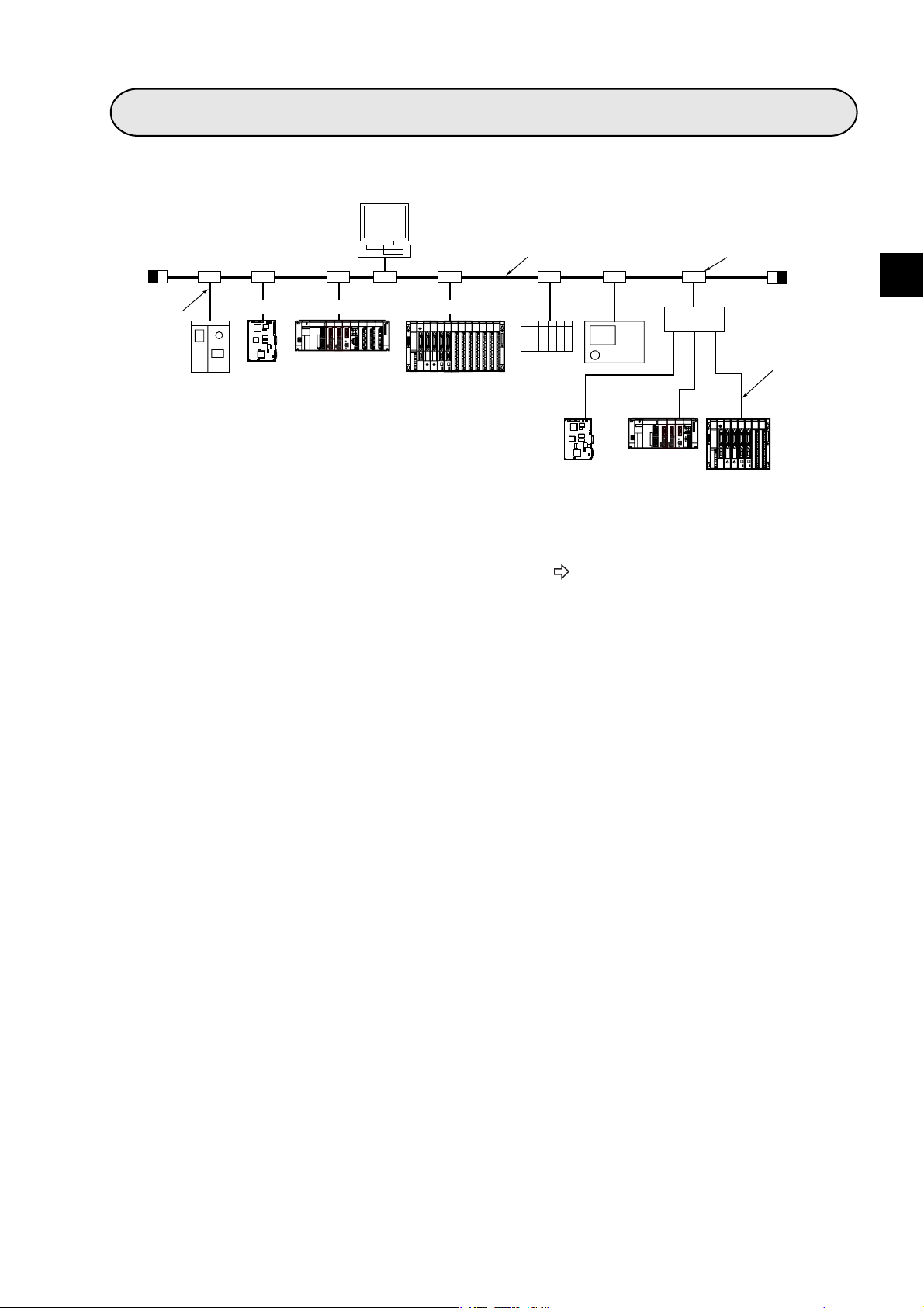
An FL-net module (JW-20FL5/20FL T, JW-50FL, FL-net board (Z-336J)) is an interface module use to connect a
programmable controller (JW20H/30H, JW50H/70H/100H), J-board to an FL-net. FL-net is an open network
that connects production equipment and controllers from multiple FA (factory automation) venders, to create a
unified production process. This network works as an intermediary between information networks and production networks, and makes it possible to connect control devices (such as personal computers or programmable
controllers, hereafter referred to as PCs), to numeric control devices (CNCs), and robot controllers (RCs). The
Ethernet is used as a world standard communication method to allow communication between pieces of OA
(Office Automation) equipment.
Server
BCR
Personal
computer
WAN
ID
Graphic
panel
Image
EWS
Robot
controller
Personal
computer
Gateway
PC
Personal
computer
Information network (Ethernet)
Nut
runner
Field network
NC
Personal
computer
FL-net
Printer
1
Sensor
actuator
FL-net employs an FA link protocol as an application layer.
Features of the FA link protocol
1 Uses the Ethernet UDP/IP communication protocol.
2 Using a Master-less, Token method, the system prevents data transmission conflicts and guarantees
the transfer of data within a specified time.
3 Employs a shared memory system (shares information between each of the nodes).
4 Nodes can automatically enter and leave the network.
Features of the JW-20FL5/20FLT, JW-50FL, Z-336J
1 FL-net compatible (uses the FA link protocol)
2 Supports cyclic transfers and message transfers.
3 Supports exchange of data between SHARP PCs using the SEND/RECEIVE function. (A unique
function of SHARP equipment)
4 Allows remote programming and remote monitor functions between SHARP PCs. (A unique function of
SHARP equipment)
- FL-net is an open network that was standardized by the Japan FA Open Systems Promotion Group (JOP) in
the Manufacturing Science Technology Center (MSTC).
- Ethernet is a registered trademark of XEROX CORPORATION, USA.
1-1
Page 12

Chapter 2: Handling Precautions
Make sure to follow the precautions bellow who using the JW-20FL5/20FL T, JW-50FL (hereafter referred to
as this module) and Z-336J (hereafter referred to as this board).
(1) Installation
- Do not install or store this unit in the following conditions.
1 Locations close to a heating element
2 Sudden temperature changes which may cause condensation
3 Corrosive or inflammable gas
4 Vibration or hard jolts
- The minimum distance between nodes is specified in the regulations. (2.5 m when the 10BASE5
is used.) When connecting devices, be sure to maintain these minimum distances.
Cables used for 10BASE5 systems have marks every 2.5 m. Position each transceiver directly
on one of these marks.
- Mount the transceivers on electrically insulated objects, such as a wooden mounting block.
- Prior to installing or detaching the JW20H/30H or JW50H/70H/100H, make sure to turn OFF the
power supply to the PCs.
- Prior to connect the board, make sure to turn OFF the power to the J-board.
- Isolate the hub case electrically from the control panel chassis.
(2) Treatment
JW-20FL5/20FLT and JW-50FL
- For ventilation, holes are provided in the cabinet to prevent a temperature rise. Do not block
the ventilation holes. Good ventilation is necessary.
- Never allow a liquid such as water and chemical solution and a metallic object like a copper wire
inside this module to avoid a possible hazard. Otherwise, it may be a cause of machine
trouble.
- When a trouble or abnormal condition such as overheat, fume, or smoke is met, stop the
operation immediately, and call your dealer or our service department.
Z-336J
A J-board is a PC board which contains sensitive electronic parts. Therefore, be careful when handling it.
1 Before touching the board with your hand, make sure to discharge all static electricity from
your body.
2 Do not touch the board if your hands are dirty or wet.
3 Do not put the board down on a conductive object (such as a metal plate).
(If a J-board with a CPU is placed on a conductive object, the battery terminals may be short
circuited and the back up memory will be lost.)
4 Do not handle any switches, connectors, or terminal blocks on the J-board using excessive
force.
2
(3) Grounding
- Connect the J-board FG terminal (on the terminal block on the CPU board) to an independent
class 3 ground. Do not share the ground with high voltage equipment.
- The hexagonal standoffs (supplied with each board) for assembling the J-board are used for
connecting the ground (FG). Make sure to tighten them securely.
(4) Wiring precautions
- Install the communication lines at a distance of 60 cm or more away from motor power lines or
high voltage lines.
- Do not route wires near equipment that generates electrical noise.
- Use category 5 10BASE-T shielded twisted pair cable.
- Use an isolated shield transformer to provide power to the hubs.
- We recommend using a transceiver cable that is 2 m or shorter.
2-1
Page 13
Chapter 3: System Configuration
[Connection example]
Personal
computer
Terminator
Transceiver
cable
(max. 50 m)
RC
FL-net
J-board
2
1
Z-336J
JW20H/30H
JW-20FL5
10BASE5 coaxial cable (max. 500 m)
JW50H/70H/100H
RC
JW-50FL
Other
maker’s
PC
J-board
Z-336J
NC
JW20H/30H
2
1
JW-20FLT
Transceiver
Hub
10BASE-T
twisted pair cable
(max. 100 m)
JW50H/70H
/100H
JW-50FL
- A basic system (segment) configuration consists of a 10BASE5 coaxial cable between 10m and 500 m long
with nodes connected to this cable. (A maximum of 100 nodes can be connected per segment)
- If the distance between nodes exceeds 500 m, use a repeater (maximum length 2,500 m).
See 7-1[1] 10BASE5 system.
Note: 10BASE5 coaxial cable, transceivers, transceiver cables, terminators, hubs, and 10BASE-T twisted
pair cable is supplied and installed by the customer.
3
3-1
Page 14
Chapter 4: Name and Function of Each Part
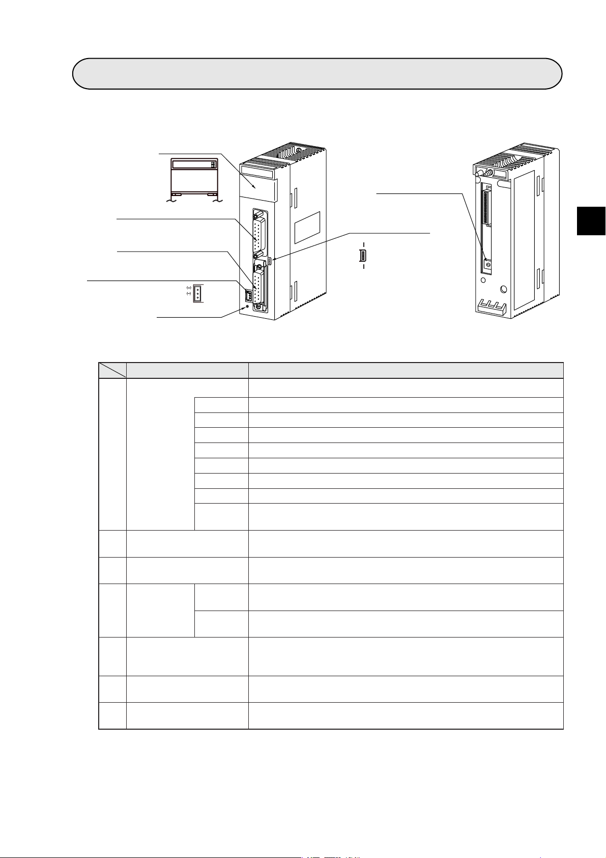
4-1 JW-20FL5
1Display panel
JW-20FL5
LNTXRX12V TPEHE
S7S6S5S4S3S2S1S0
2Connector for programmer
3Connector for 10BASE5
512 VDC power supply input terminal
FG
7Reset switch
Chapter 4: Name and Function of Each Part
6Module No. switch
(Factory setting: 0)
Connector for shield
4
switch for 10BASE5
ON
S
H
I
E
OFF
L
D
2
3
1
4
0
5
9
6
8
7
(Factory setting: ON)
4
(Front) (Rear)
Name Function
Display panel Displays the JW-20FL5 operating status using LEDs.
LN Lights when communicating normally.
TX Blink at transmitting data.
RX Blink at receiving data.
1
12 V Lights when 12 VDC is supplied. (Only when 10BASE5 is used.)
T Lights at test mode. (Normally, this is not used.)
PE Lights at parameter setting error.
HE Lights at this module error.
Displays the station number when operating normally. Displays an error
code if an error occurs.
Connect a JW-14PG programmer or similar equipment to set the
parameters on the JW-20FL5.
Connect the 10BASE5 transceiver cable.
Make sure to slide the lock securely to the "lock" position.
The shield on the coaxial cable and the FG (base) terminal on this
module will be shorted together.
The shield on the coaxial cable is not shorted to the base.
- Ground the FG line on the 12 VDC connector separately.
When 10BASE5 is used, connect a commercially available DC power
supply that is designed to supply power to transceivers. The DC power
supply must provide 12VDC ±5% and 0.5 A or more.
Specify a module number from 0 to 6.
-Becareful do not use the same number for another option module.
Connector for programmer
2
Connector for 10BASE5
3
Connector for
Shield switch
4
for 10BASE5
12 VDC power supply
5
input terminal
Module No. switch
6
S0 to S7
ON
OFF
Reset switch Only used by SHARP engineers. Users should not press this switch.
7
4-1
Page 15
Chapter 4: Name and Function of Each Part
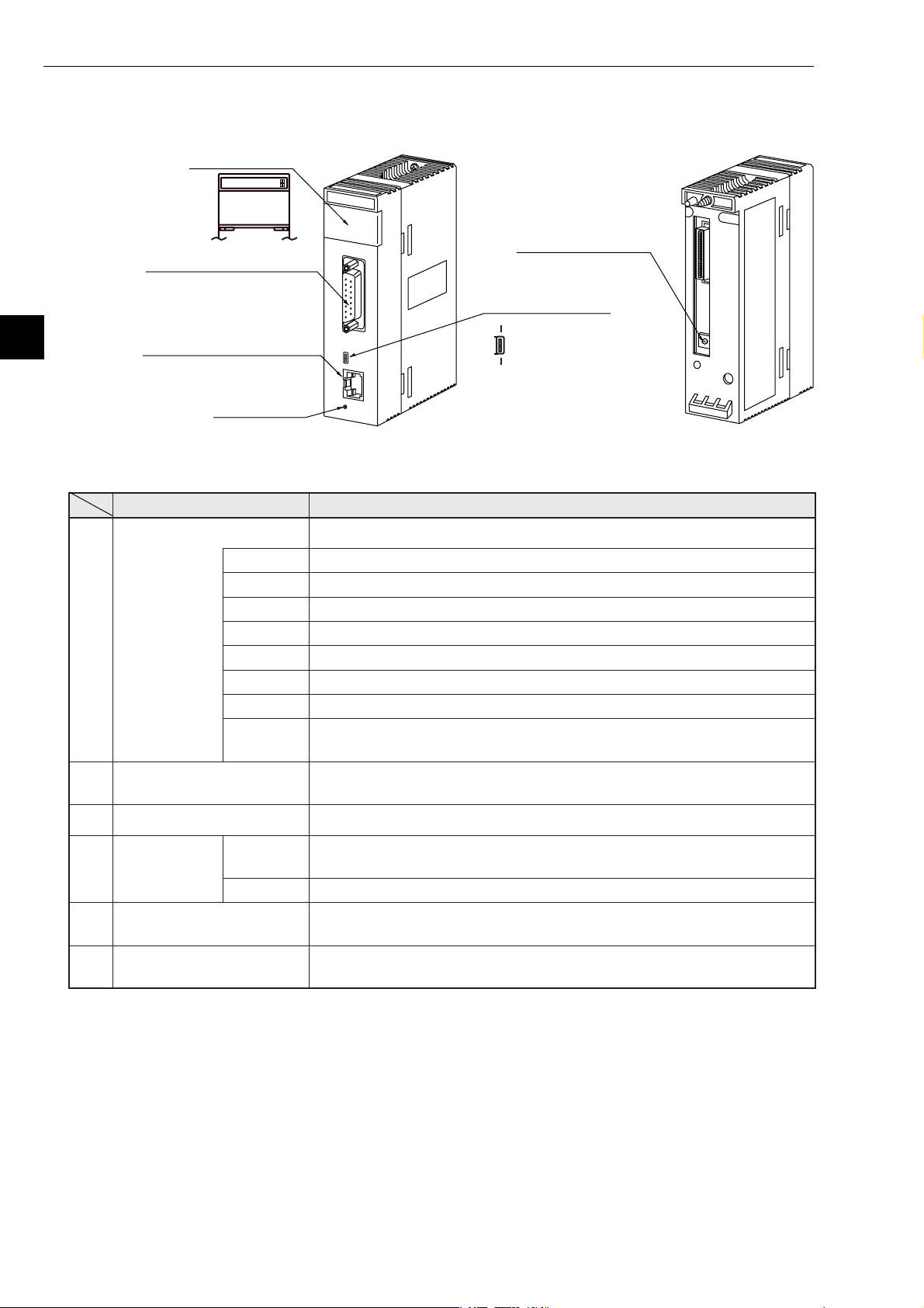
4-2 JW-20FLT
1Display panel
JW-20FLT
LNTXRX12V TPEHE
S7S6S5S4S3 S2S1 S0
2Connector for programmer
4
3Connector for 10BASE-T
6Reset switch
5Module No. switch
(Factory setting: 0)
4
Connector for shield
switch for 10BASE-T
ON
S
OFF
H
I
E
L
D
2
3
1
4
0
5
9
6
8
7
(Factory setting: ON)
(Front) (Rear)
Name Function
Display panel Displays the JW-20FLT operating status using LEDs.
LN Lights when communicating normally.
TX Blink at transmitting data.
RX Blink at receiving data.
1
12 V Cannot be used with the JW-20FLT.
T Lights at test mode. (Normally, this is not used.)
PE Lights at parameter setting error.
HE Lights at this module error.
S0 to S7
Connector for programmer
2
Connector for 10BASE-T Connect the 10BASE-T twisted pair.
3
Connector for
Shield switch
4
for 10BASE-T
Module No. switch
5
ON
OFF The shield on the twisted pair cable is not shorted to the base.
Displays the station number when operating normally. Displays an error
code if an error occurs.
Connect a JW-14PG programmer or similar equipment to set the
parameters on the JW-20FLT.
The shield on the twisted pair cable will be shorted to the FG (base) of
this module.
Specify a module number from 0 to 6.
-Becareful do not use the same number for another option module.
Reset switch Only used by SHARP engineers. Users should not press this switch.
6
4-2
Page 16
Chapter 4: Name and Function of Each Part
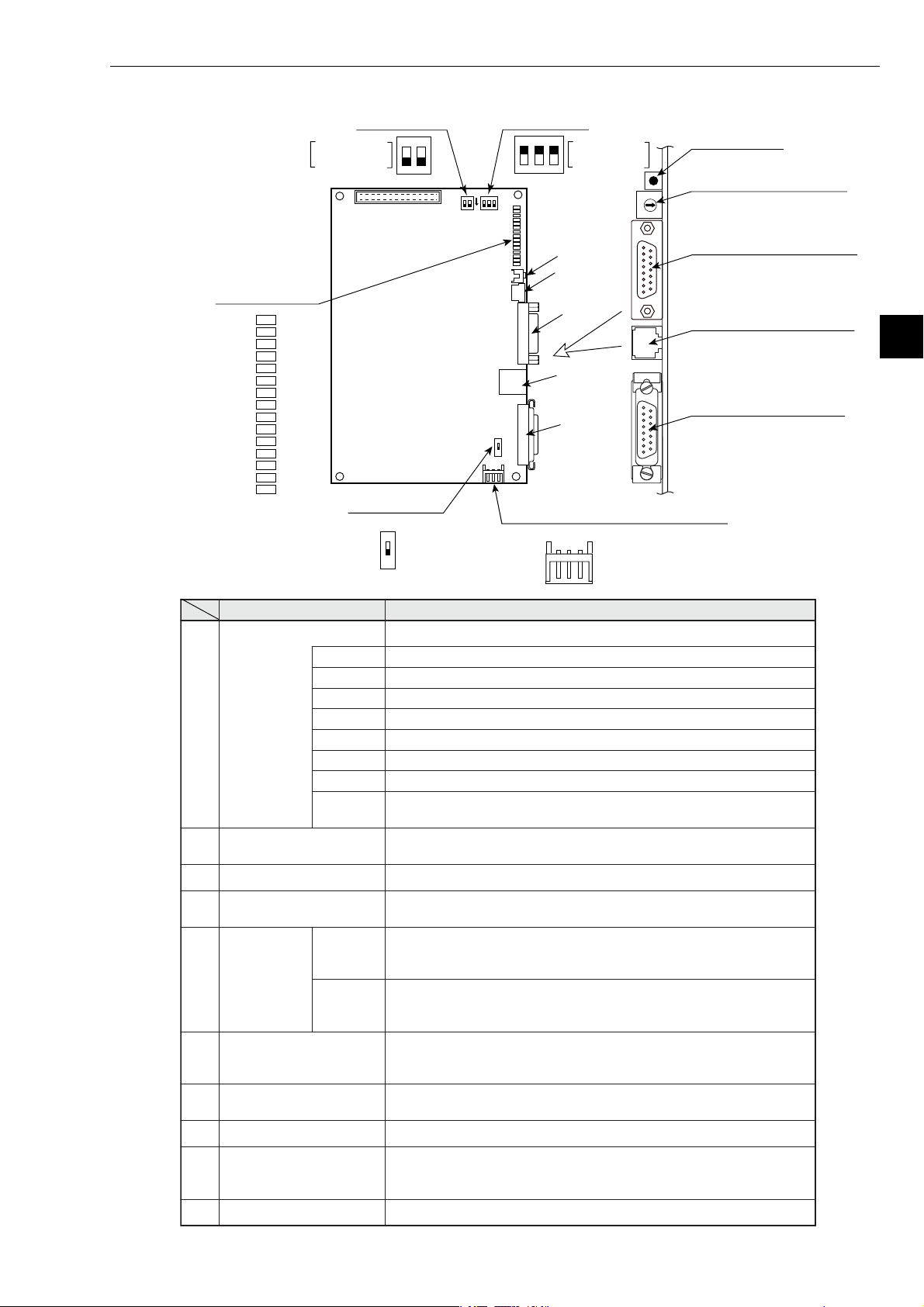
4-3 Z-336J
1Display panel
Factory setting
: ON
LN
TX
RX
12V
T
PE
HE
S7
S6
S5
S4
S3
S2
S1
S0
9Switch SWA 0Switch SW1
F
F
F
2
1O
5Switch SW6
SW6
(Factory setting: ON)
ON
SWA
O
F
F
ON
2
1
SWA
F
2
3
LN
TX
SW1
RX
12V
T
PE
HE
S7
S6
S5
S4
S3
S2
S1
S0
SW6
ON
612 VDC power supply input terminal
Factory setting
: ON
1O
SW1
⑧
⑦
②
③
④
8Reset switch
7Module No. switch SW4
8
7
9
6
0
5
1
4
2
3
(Factory setting: 0)
2Connector for programmer
3Connector for 10BASE-T
4
4Connector for 10BASE5
FG 0V 12V
Name Function
Display panel Displays this board operating status using LEDs.
LN Lights when communicating normally.
TX Blink at transmitting data.
RX Blink at receiving data.
1
12 V Lights when 12 VDC is supplied. (Only when 10BASE5 is used.)
T Lights at test mode. (Normally, this is not used.)
PE Lights at parameter setting error.
HE Lights at this board error.
S0 to S7
Connector for programmer
2
Connector for 10BASE-T Connect the 10BASE-T coaxial cable.
3
Connector for 10BASE5
4
Displays the station number when operating normally. Displays an error
code if an error occurs.
Connect a JW-14PG programmer or similar equipment to set the
parameters on this board.
Connect the 10BASE5 coaxial cable.
Make sure to slide the lock securely to the "lock" position.
The shield on the cable between a 10BASE-T connector and a
5
ON
Switch SW6
OFF
10BASE5 connector and the FG (base) on this module will be shorted
together.
The shield on the cable between a 10BASE-T connector and a
10BASE5 connector is not shorted to the base.
- Ground the FG line on the 12 VDC connector separately.
12 VDC power supply
6
input terminal
Module No. switch
7
Reset switch Only used by SHARP engineers. Users should not press this switch.
8
Number of communication
boards
9
Switch SWA
Switch SW1 No need to set this switch for the Z-336J. (Always set to OFF (default).)
0
When 10BASE5 is used, connect a commercially available DC power
supply that is designed to supply power to transceivers. The DC power
supply must provide 12VDC ±5% and 0.5 A or more.
Specify a module number from 0 to 6.
-Becareful do not use the same number for another option board.
Specify the number of communication boards actually installed
(including the Z-336J).
- See pages 5-3 to 5-7.
4-3
Page 17
Chapter 4: Name and Function of Each Part
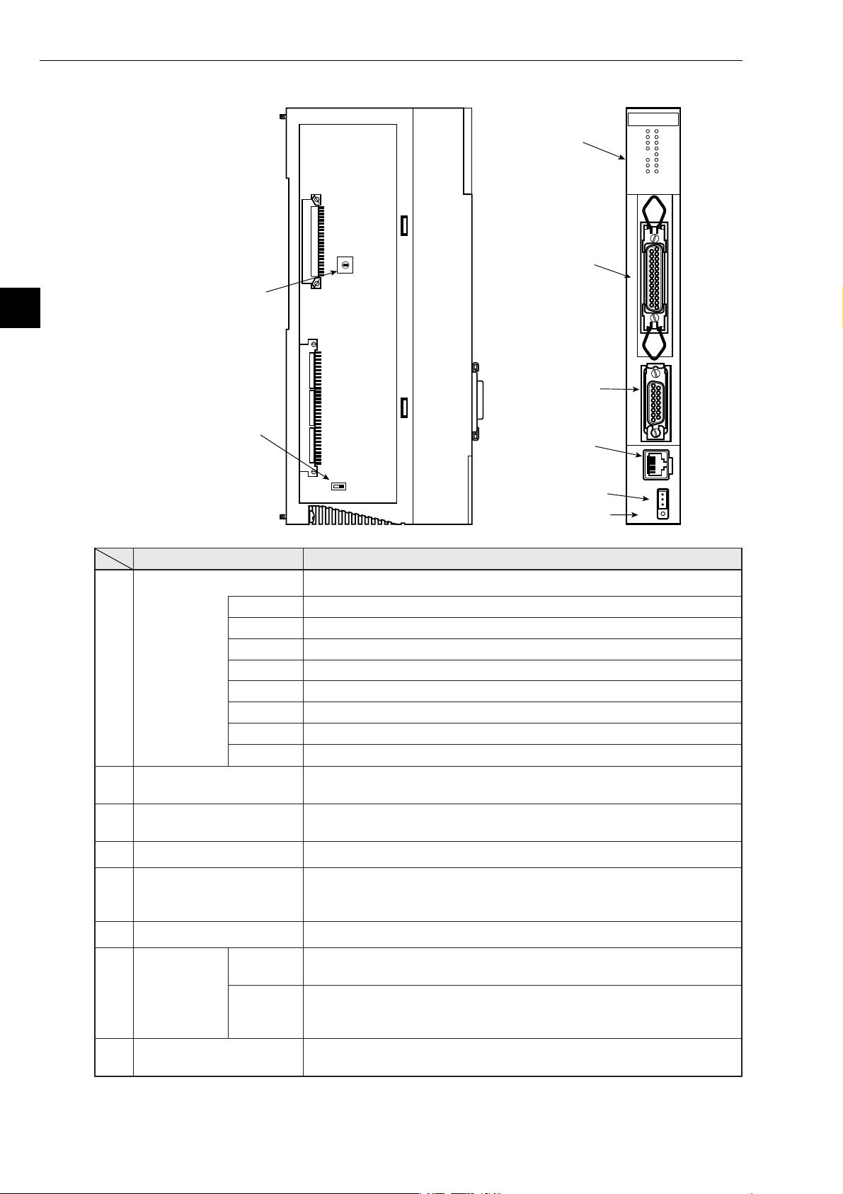
4-4 JW-50FL
1 LED indicator
JW-50FL
LNK
TX
RX
DC12V
TEST
PER
HER
S0
S1
S2
S3
S4
S5
S6
S7
4
8 Switch SW3
(Factory setting: 0)
3
2 Connector for
2
4
1
5
0
6
9
7
8
SW3
programmer
P
R
O
G
R
A
M
M
E
R
3 Connector for
7 Switch SW3
(Factory setting: ON)
10BASE5
4 Connector for
10B5
10BASE-T
10B-T
RESET
12VIN
(+)
(−)
FG
SW2
OFF ON
5 12 VDC power
supply input terminal
6 Reset switch
Name Function
Display panel Displays the JW-50FL operating status using LEDs.
LNK Lights at operating. Lights OFF at stopping.
TX Blink at transmitting data.
RX Blink at receiving data.
1
12 VDC Lights when 12 VDC is supplied. (Only when 10BASE5 is used.)
TEST Lights at test mode.
PER Lights at parameter setting error.
HER Lights at this module error.
S0 to S7 Indicates status of connection status monitor flag.
Connector for programmer
2
Connector for 10BASE5
3
Connector for 10BASE-T Connect 10BASE-T twisted-pair cable.
4
12 VDC power supply
5
input terminal
Reset switch Only used by SHARP engineers. Users should not press this switch.
6
ON
Switch SW2
7
OFF
When using a remote monitor or remote programming function, connect
a JW-14PG programmer.
Connect the 10BASE5 transceiver cable.
Make sure to slide the lock securely to the "lock" position.
When 10BASE5 is used, connect a commercially available DC power
supply that is designed to supply power to transceivers. The DC power
supply must provide 12VDC 5% and 0.5 A or more.
Turn ON when the shields on the 10BASE-T connectors or 10BASE5
connectors are connected to the FG (base) of the JW-50FL.
Turn OFF when the shields on the 10BASE-T connectors or 10BASE5
connectors are not connected to the FG.
- Ground the FG line on the 12 VDC connector separately.
Switch SW3
8
Specify a parameter address (in system memory) from 0 to 4.
- See page 12-4.
Note: Only 10BASE5 or 10BASE-T protocol is used. Mixed use of these two types is not permitted.
4-4
Page 18
Chapter 5: Installation
Chapter 5: Installation
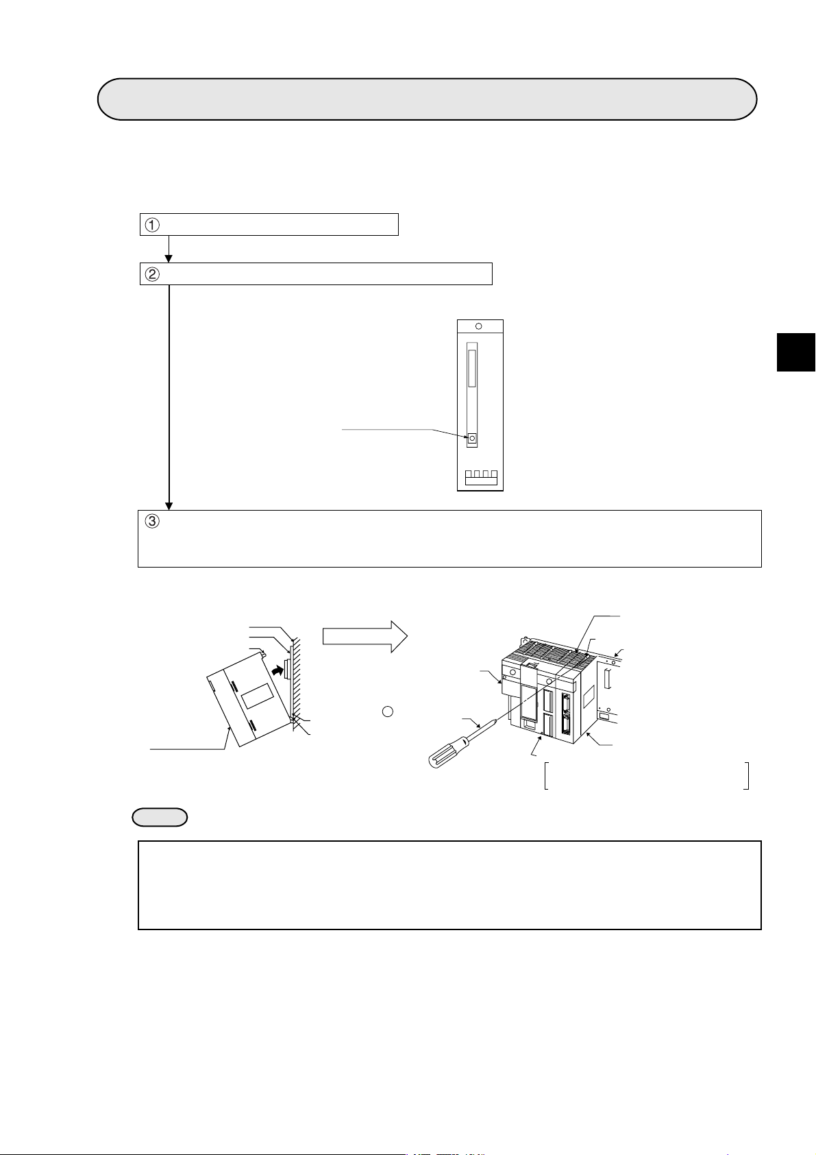
5-1 Installation of JW-20FL5/20FLT
This section describes the installation procedures for the JW-20FL5/20FLT (hereafter referred to as the
module) on the JW20H/30H basic rack panel.
Turn off the power to the JW20H/30H.
Set the module No. switch on the back of the module.
(Back of the communication module)
Module No. switch
5
Insert the mounting rib on the module into the rib insert holes on the JW20H/30H basic rack panel
and push in. Then, tighten module-mounting screws at the top of the module using a Phillips-head
(+) screwdriver.
Intermediate plate
or control panel
Basic rack panel
Module insert guide
This module
Module rib
insert hole
Module rib
(Installation example)
Power supply module
+Phillips-head
screwdriver
Control module
JW-21CU/22CU, JW-31CUH1/32CUH1
JW-33CUH1/33CUH2/33CUH3
Ventilation hole
Module mounting screw
Basic rack panel
The module
(The figure shows a JW-20FL5.)
Notes
- The module cannot be installed into an expansion rack panel.
- More than two communication modules can be installed on the same control module (basic rack panel
for the JW20H/30H). However, be careful not to use the same module No. switch setting for any other
module (including JW-20FL5/20FLT).
- Make sure to tighten the module mounting screws securely. Loose screws may cause a malfunction.
5-1
Page 19
Chapter 5: Installation
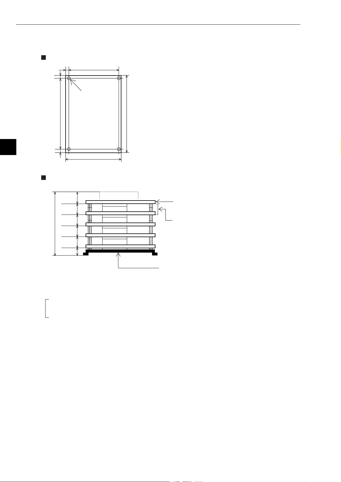
5-2 Installation of Z-336J
Board dimensions and assembled dimensions of the Z-336J are shown below.
Board dimensions
5
5
100
Boss hole: 4-φ4
[Unit: mm]
5
5
Assembled dimensions
25.0
21.6
D
D2
D2
D2
15.0
110
180170
The dimensions on the left do not include metal fittings.
[Unit: mm]
* CPU board (when Z-311J/312J is mounted)
When installing the Z-336J under the CPU board.
In the case metal fixing A is used.
* The CPU board can only be installed at the upper most position.
- For details about assembly/installation dimensions, see the manuals below.
J-board Z-311J/312J User's Manual: Hardware Version.
J-board Z-313J User's Manual: Hardware Version.
J-board Z-511J User's Manual: Hardware Version.
Dimensions D and D2 correspond to D and D2 "board sizes" of the manuals above.
- Make sure to ensure there is conductivity between the installation metal and installation section.
5-2
Page 20
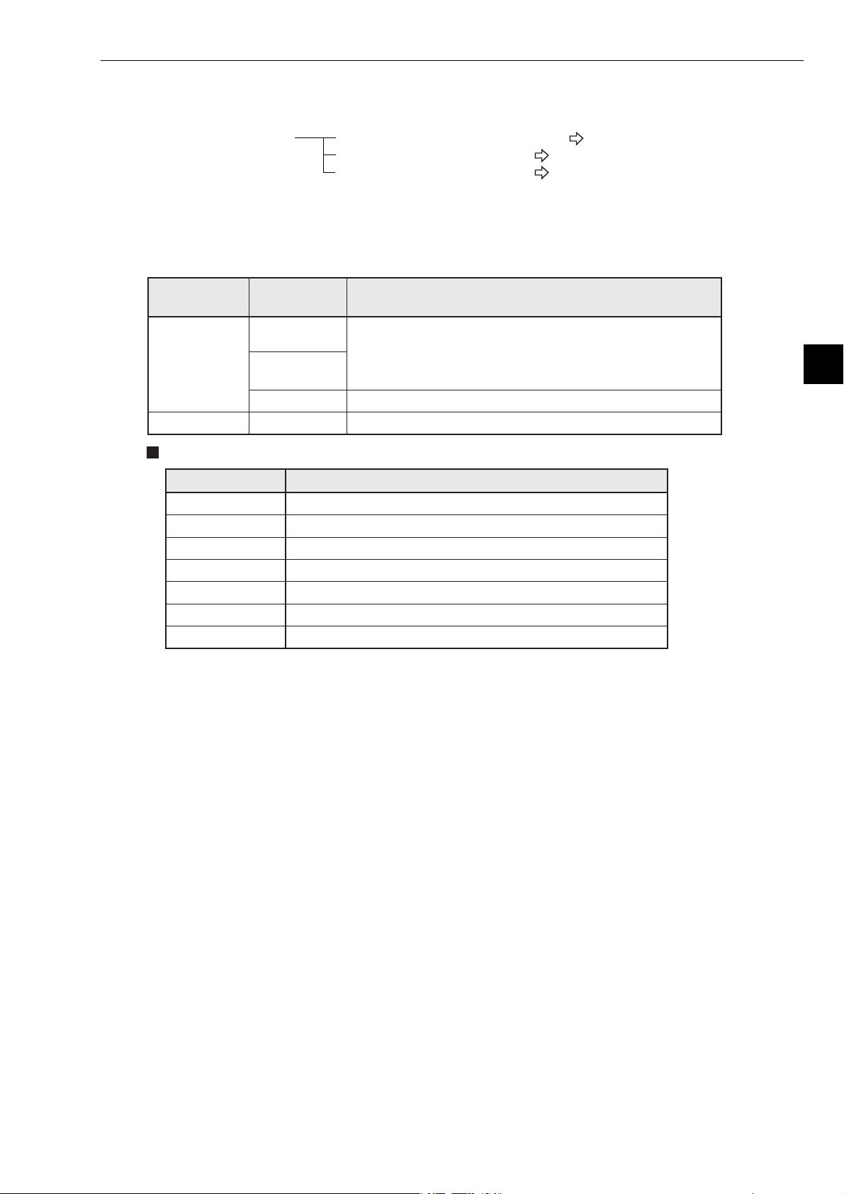
This paragraph describes the maximum number of Z-336J boards to install on the J-board and allocation of I/O
relays.
Allocation of I/O relays When mounted on the Z-311J/312J See the next page.
When mounted on the Z-313J See page 5-5.
When mounted on the Z-511J See page 5-6.
Chapter 5: Installation
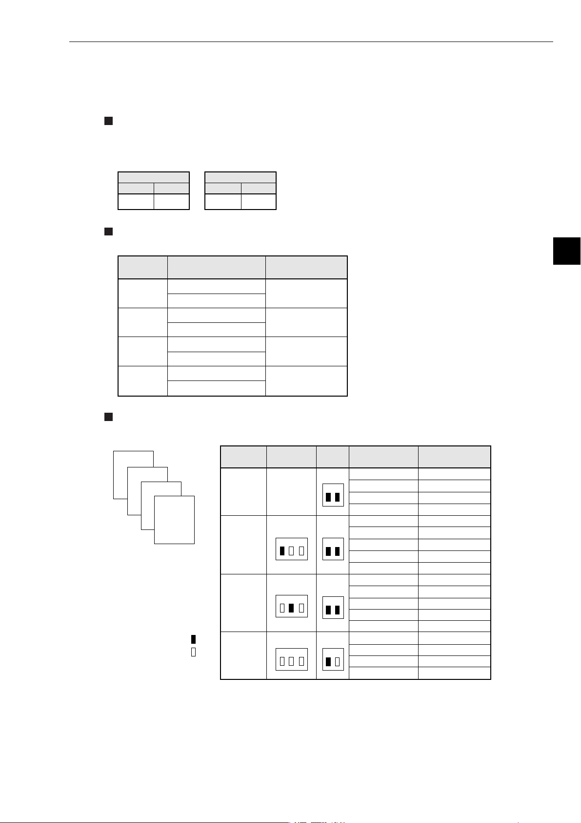
[1] Maximum number of boards to mount
The Z-336J is a kind of communication board of the J-board. Maximum number of boards mounted on
the J-board shall be the total number of communication boards mounted.
J-board CPU board
Z-311J
Z-300 series
Z-500 series Z-511J * Maximum 2
Types of communication boards
Z-312J
Z-313J * Maximum 1
Total number of boards able to be mounted including
Z-336J and other communication boards
Maximum 2
- When the total current flow at5Vofeach mounted
board exceeds 800 mA, the number of boards shall be
limited.
5
Module name Specifications
Z-331J * Data link or computer link, satellite I/O link master station
Z-332J Data link or computer link
Z-333J Satellite I/O link master station
Z-334J * ME-NET board (with branch line extension function)
Z-335J Satellite net board
Z-336J FL-net board
Z-337J DeviceNet board
* Manufactured on request.
5-3
Page 21
Chapter 5: Installation
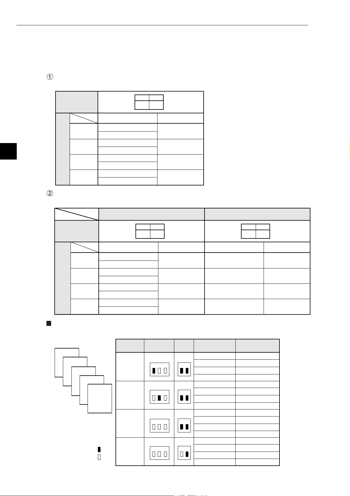
[2] Address allocation of I/O relay
This section describes I/O relay addresses allocated to the Z-336J.
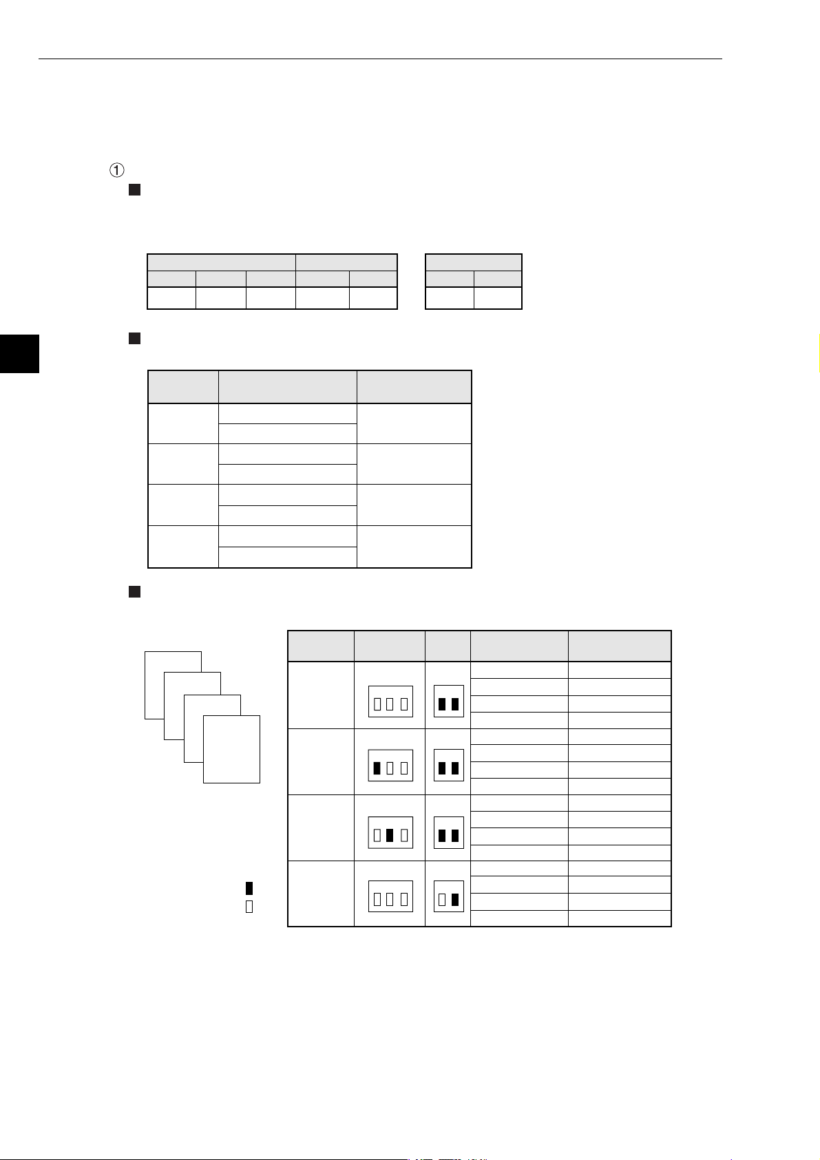
(1) When mounted on Z-311J/312J
The total number of Z-336J boards able to be mounted including other communication boards is two
at maximum. Below the switch settings of the Z-336J and allocation of I/O relay are shown.
When using one communication board (Z-336J)
Set switch SWA for number of communication boards on the Z-336J as follows.
5
Setting of
switch SWA
on the Z-336J
I/O relay address
Z-336J
(optional)*
Dummy
(vacant)
Dummy
(vacant)
Dummy
Allocation of Z-336J
I/O relay
(vacant)
When using two communication boards
Depending on at which position the Z-336J is used, the allocation of I/O relay varies.
Setting of
switch SWA
on the Z-336J
Z-336J
(optional)*
Dummy
(vacant)
Dummy
(vacant)
Dummy
Allocation of Z-336J
I/O relay
(vacant)
コ0000
コ0001
コ0002
コ0003
コ0004
コ0005
コ0006
コ0007
Use Z-336J as first unit
I/O relay address
コ0000
コ0001
コ0002
コ0003
コ0004
コ0005
コ0006
コ0007
1
ON
1
ON
2
ON
Address to set
R = 0, S = 0
R = 0, S = 1
R = 0, S = 2
R = 0, S = 3
2
ON
Address to set
R = 0, S = 0
R = 0, S = 1
R = 0, S = 2
R = 0, S = 3
* Though it is allocated as optional,
it will be a dummy area not
functionally used.
Use Z-336J as 2nd unit
2
1
ON
OFF
I/O relay address
コ0010
コ0011
コ0012
コ0013
コ0014
コ0015
コ0016
コ0017
Address to set
R = 0, S = 4
R = 0, S = 5
R = 0, S = 6
R = 0, S = 7
Examples of allocation
Below the switch setting and I/O allocation when using two Z-336J is shown.
Z-336J
4
3
Z-336J
Z-322J
2
1
Z-322J
Z-311J
/312J
ON
OFF
Mounted
position
1
2
3
4
SW1
(RACK NO)
1 2 3
1 2 3
1 2 3
1 2 3
SWA
(SW2)
SW2
1 2
SW2
1 2
SWA
1 2
SWA
1 2
I/O relay
address
コ0020, コ0021
コ0022, コ0023
コ0024, コ0025
コ0026, コ0027
コ0030, コ0031
コ0032, コ0033
コ0034, コ0035
コ0036, コ0037
コ0000, コ0001
コ0002, コ0003
コ0004, コ0005
コ0006, コ0007
コ0010, コ0011
コ0012, コ0013
コ0014, コ0015
コ0016, コ0017
Address to set
R=1, S=0
R=1, S=1
R=1, S=2
R=1, S=3
R=2, S=0
R=2, S=1
R=2, S=2
R=2, S=3
R=0, S=0
R=0, S=1
R=0, S=2
R=0, S=3
R=0, S=4
R=0, S=5
R=0, S=6
R=0, S=7
5-4
Page 22
(2) When mounted on Z-313J
The number of boards available mounted on the Z-336J including other communication boards is
one at maximum.
Below shows the switch setting of the Z-313J and Z-336J as well as I/O relay allocation of the Z336J.
Switch setting
The set switch SWA on the Z-313J and the number of communication boards setting switch SWA of
the Z-336J are as shown below.
Chapter 5: Installation
- Z-313J
Switch SWA
1 2
ON ON
Allocation of I/O relay
I/O relay address of the Z-336J shall be allocated as shown below.
Allocation
details
Z-336J
(optional)*
Dummy
(vacant)
Dummy
(vacant)
Dummy
(vacant)
Allocation examples
Below shows switch setting and I/O relay allocation when using one Z-336J.
- Z-336J
Switch SWA
1 2
OFF ON
I/O relay address
コ0010
コ0011
コ0012
コ0013
コ0014
コ0015
コ0016
コ0017
Address to set
R = 0, S = 4
R = 0, S = 5
R = 0, S = 6
R = 0, S = 7
* Though it is allocated as optional,
it will be a dummy area not
functionally used.
5
Z-336J
4
3
Z-325J
Z-325J
2
1
Z-313J
ON
OFF
Mounted
position
1
2
3
4
SW1
(RACKNO.)
1 2 3
1 2 3
1 2 3
(SW2)
NO
SWA
SWA
1 2
SW2
1 2
SW2
1 2
SWA
1 2
I/O relay
address
コ0000, コ0001
コ0002, コ0003
コ0004, コ0005
コ0006, コ0007
コ0020, コ0021
コ0022, コ0023
コ0024, コ0025
コ0026, コ0027
コ0030, コ0031
コ0032, コ0033
コ0034, コ0035
コ0036, コ0037
コ0040, コ0041
コ0042, コ0043
コ0010, コ0011
コ0012, コ0013
コ0014, コ0015
コ0016, コ0017
Address to set
R=0, S=0
R=0, S=1
R=0, S=2
R=0, S=3
R=1, S=0
R=1, S=0
R=1, S=1
R=1, S=2
R=1, S=3
R=2,S=0
R=2,S=0
R=2,S=1
R=2,S=2
R=2,S=3
R=0,S=4
R=0,S=5
R=0,S=6
R=0,S=7
5-5
Page 23
Chapter 5: Installation
(3) When mounted on Z-511J
5
The number of boards available mounted on the Z-336J including other communication boards is
two at maximum.
Below shows the switch setting of the Z-511J and Z-336J as well as I/O relay allocation of the Z336J.
When using one communication board (Z-336J)
Switch setting
The set switches SW1 and SWA on the Z-511J and the number of communication boards setting
switch SWA on the Z-336J are as follows.
- Z-511J
Switch SWA Switch SWASwitch SW1
1 2 3
OFF OFF OFF
Allocation of I/O relay
I/O relay address of the Z-336J shall be allocated as shown below.
1 2
ON ON
- Z-336J
1 2
OFF ON
Allocation
details
Z-336J
(optional)*
Dummy
(vacant)
Dummy
(vacant)
Dummy
(vacant)
Allocation examples
Below shows switch setting and I/O relay allocation when using one Z-336J.
Z-336J
Z-322J
4
Z-322J
3
2
I/O relay address
コ0010
コ0011
コ0012
コ0013
コ0014
コ0015
コ0016
コ0017
Z-511J
1
ON
OFF
Mounted
position
1
2
3
4
Address to set
R = 0, S = 4
R = 0, S = 5
R = 0, S = 6
R = 0, S = 7
SW1
(RACK NO)
1 2 3
1 2 3
1 2 3
1 2 3
SWA
(SW2)
SWA
1 2
SW2
1 2
SW2
1 2
SW2
1 2
* Though it is allocated as optional,
it will be a dummy area not
functionally used.
I/O relay
address
コ0000, コ0001
コ0002, コ0003
コ0004, コ0005
コ0006, コ0007
コ0020, コ0021
コ0022, コ0023
コ0024, コ0025
コ0026, コ0027
コ0030, コ0031
コ0032, コ0033
コ0034, コ0035
コ0036, コ0037
コ0010, コ0011
コ0012, コ0013
コ0014, コ0015
コ0016, コ0017
Address to set
R=0, S=0
R=0, S=1
R=0, S=2
R=0, S=3
R=1, S=0
R=1, S=1
R=1, S=2
R=1, S=3
R=2, S=0
R=2, S=1
R=2, S=2
R=2, S=3
R=0, S=4
R=0, S=5
R=0, S=6
R=0, S=7
5-6
Page 24
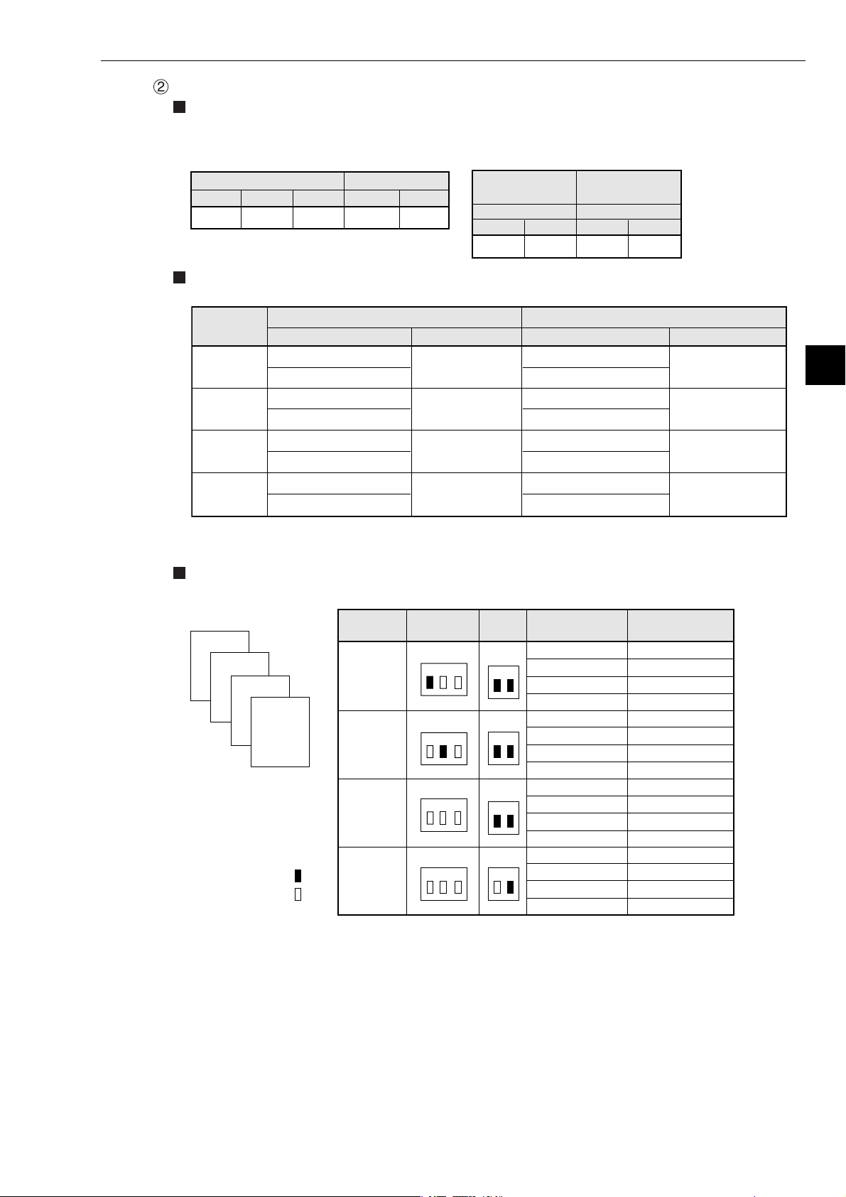
When using two communication boards (Z-336J)
Switch setting
The set switches SW1 and SWA on the Z-551J and the number of communication boards setting
switch SWA on the Z-336J are as follows.
- Z-511J
Switch SW1
1 2 3
OFF OFF OFF
Allocation of I/O relay
I/O relay address of the Z-336J shall be allocated as shown below.
Allocation
details
Z-336J
(optional)*
Dummy
(vacant)
Dummy
(vacant)
Dummy
(vacant)
* Though it is allocated as optional, it will be a dummy area not functionally used.
Use Z-336J as 1st unit Use Z-336J as 2nd unit
I/O relay address
コ0000
コ0001
コ0002
コ0003
コ0004
コ0005
コ0006
コ0007
Switch SWA
1 2
ON ON
Address to set
- Z-336J
Use Z-336J
as 1st unit
Switch SWA Switch SWA
1 21 2
ON ON
R = 0, S = 0
R = 0, S = 1
R = 0, S = 2
R = 0, S = 3
Use Z-336J
as 2nd unit
OFF ON
I/O relay address
コ0010
コ0011
コ0012
コ0013
コ0014
コ0015
コ0016
コ0017
Chapter 5: Installation
Address to set
R = 0, S = 4
R = 0, S = 5
R = 0, S = 6
R = 0, S = 7
5
Allocation examples
Below shows switch setting and I/O relay allocation when using two Z-336Js.
Z-336J
4
3
Z-336J
Z-322J
2
1
Z-511J
ON
OFF
Mounted
position
1
2
3
4
SW1
(RACK NO)
1 2 3
1 2 3
1 2 3
1 2 3
SWA
(SW2)
SWA
1 2
SWA
1 2
SWA
1 2
SWA
1 2
I/O relay
address
コ0020, コ0021
コ0022, コ0023
コ0024, コ0025
コ0026, コ0027
コ0030, コ0031
コ0032, コ0033
コ0034, コ0035
コ0036, コ0037
コ0000, コ0001
コ0002, コ0003
コ0004, コ0005
コ0006, コ0007
コ0010, コ0011
コ0012, コ0013
コ0014, コ0015
コ0016, コ0017
Address to set
R=1, S=0
R=1, S=1
R=1, S=2
R=1, S=3
R=2, S=0
R=2, S=1
R=2, S=2
R=2, S=3
R=0, S=0
R=0, S=1
R=0, S=2
R=0, S=3
R=0, S=4
R=0, S=5
R=0, S=6
R=0, S=7
5-7
Page 25
Chapter 5: Installation
5-3 JW-50FL
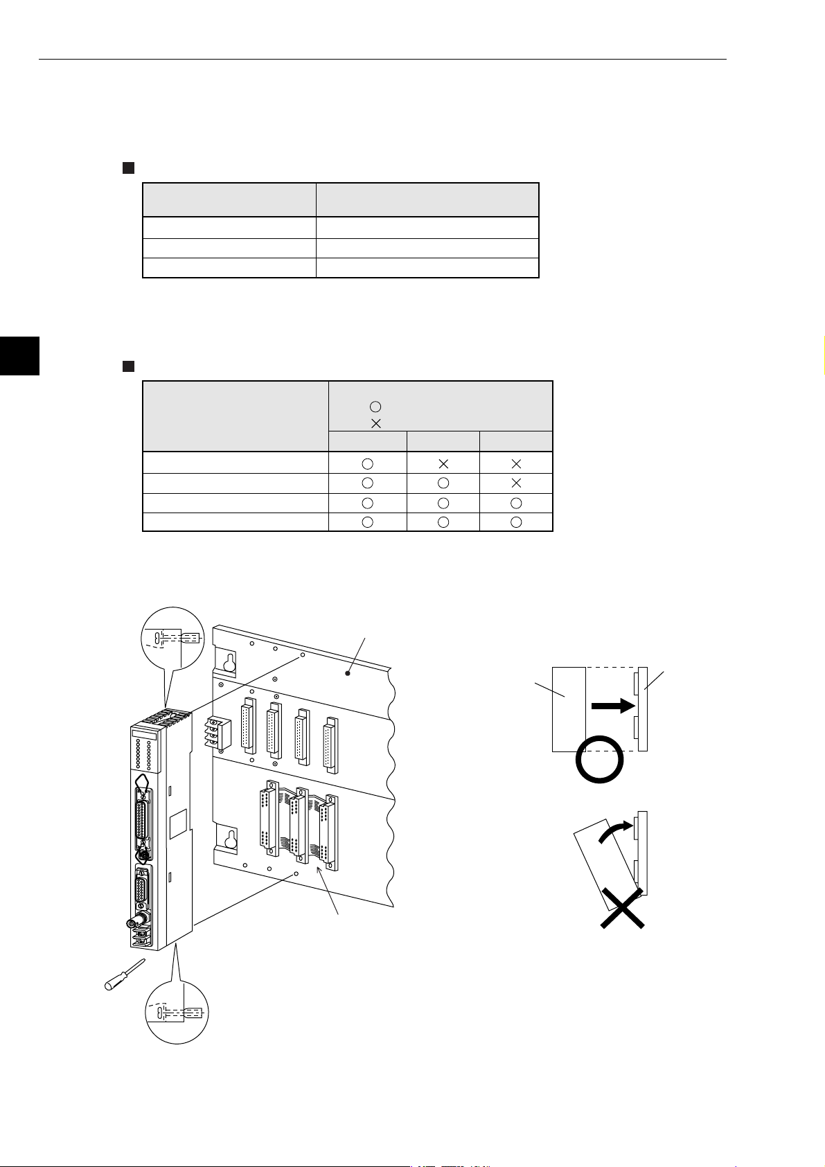
(1) Installation of cable for option module
Install the optional cable on the basic rack panel that installed JW-50FL.
Cable type for option module
5
Cable for option module
ZW-2CC
ZW-4CC
ZW-6CC
* If the ZW-6CC is used, a maximum of 6 optional modules can be installed. However, a limit of
5 optional modules can be used with JW-50FL, due to a parameter (address area) setting limitation.
Rack panel type
Model name of the rack
panel on which optional
cable is installed
JW-4BU
JW-6BU
JW-8BU
JW-13BU
(2) Installation of JW-50FL
Attach the rack panel using the two attachment screws.
Before installation or removal, make sure to shut OFF the power supply to the PC.
Maximum number of JW-50FL
that can be installed
2
4
Note *
5
Cable for option module
(: Can be installed
ZW-2CC ZW-4CC
: Cannot be installed)
ZW-6CC
Phillips screwdriver
Install on rack panel JW-4BU
Module
Appearance when ZW-2CC optional
cable is installed
- This module can be installed in any one of the optional slots.
Be careful not to bend the connector pins on the module by applying
too much force to them.
Rack panel
5-8
Page 26

Chapter 6: Connection/Wiring
Chapter 6: Connection/Wiring
6-1 Installing an Ethernet cable
Workers who will install or hook up an Ethernet cable must have special training and knowledge, such as
the safety procedures and standards required by this technology (JIS X5252).
We recommend that you contact a specialist for perform any installation or hook up. (Sharp Document
Systems Co., Ltd. is providing the Ethernet installation work service, and supplying network products
from Allied System Co., Ltd.)
[1] Equipment layout
- The minimum distance between nodes is specified in the regulations. (2.5 m when the 10BASE5 is
used.) When connecting devices, be sure to maintain these minimum distances.
Cables used for 10BASE5 systems have marks every 2.5 m. Position each transceiver directly on one
of these marks.
-Mount the transceivers on electrically insulated objects, such as a wooden mounting block.
[2] Wiring
- Separate (60 cm or more) the data transmission cables from power cables.
- Do not run cables near any noise generating source.
- Both ends of the coaxial cable must be terminated with a termination resistance. Make sure to install
termination resistance on each end.
6
6-1
Page 27
Chapter 6: Connection/Wiring
6-2 Connection
[1] Connection of JW-20FL5
This paragraph describes how to connect 10BASE5 cable to the JW-20FL5.
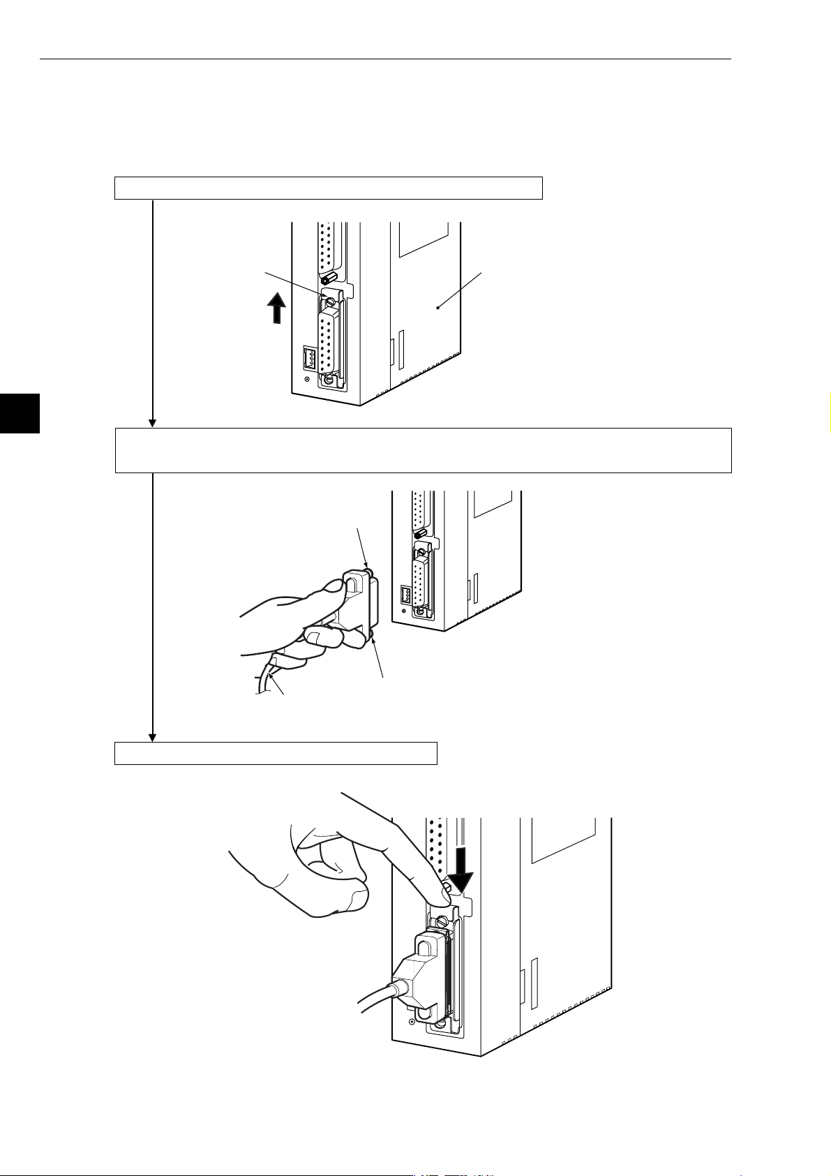
(1) Connecting the transceiver cable
1 Slide the lock on the 10BASE5 connector (on the JW-20FL5) up.
6
Slide lock
R
E
S
E
T
JW-20FL5
2 Insert the connector so that the two locking posts on the cable connector match the holes on
the slide lock.
Locking post
RESET
Locking post
Transceiver cable
3 Slide the lock down to lock the cable connector.
RESET
6-2
Page 28
Chapter 6: Connection/Wiring
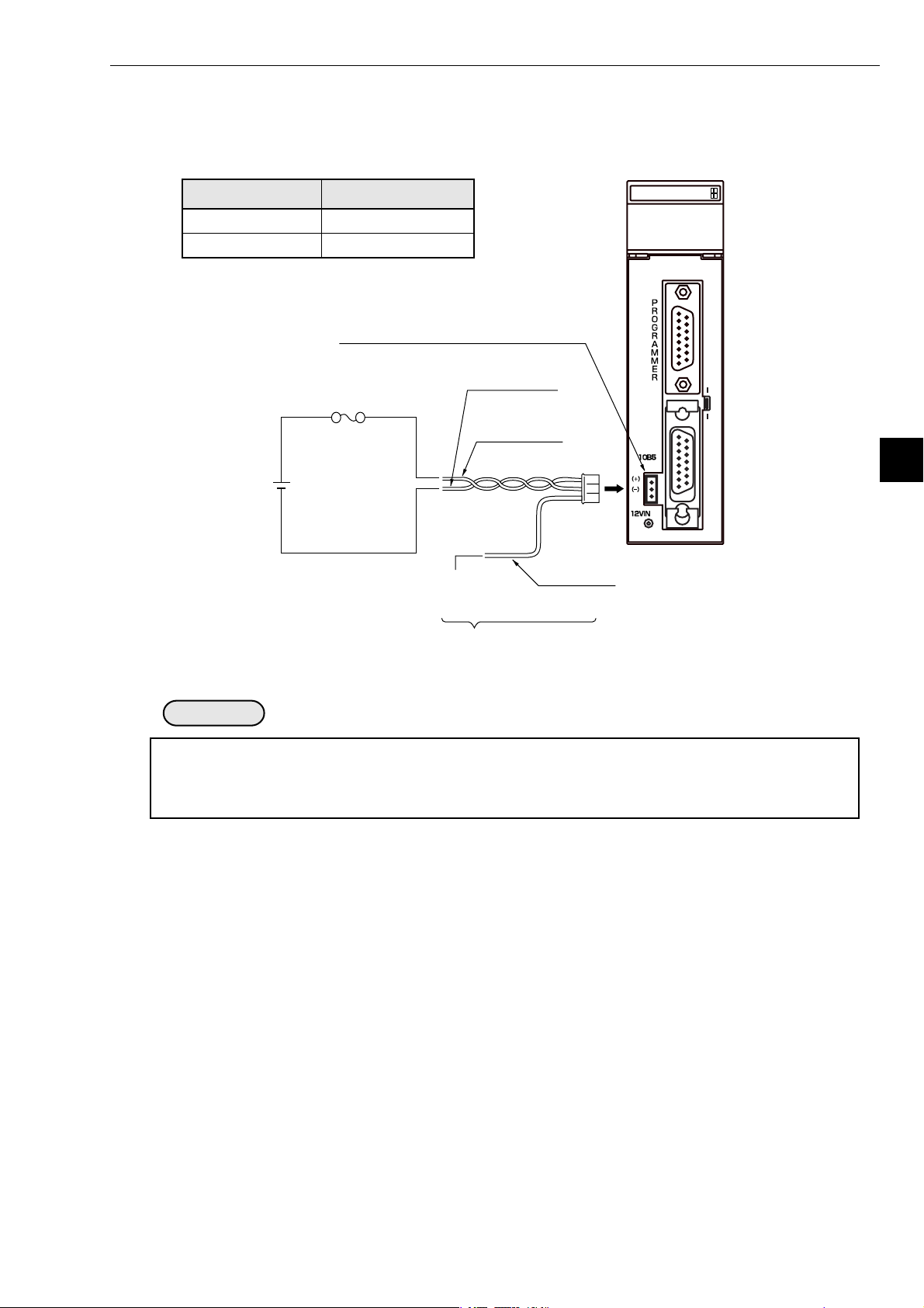
(2) Wiring the power source
When a 10BASE5 is used, 12 VDC power should be supplied to the transceiver.
Supply power to the 12 VDC power supply input terminal using a commercial constant voltage power
supply unit.
Item Specifications
Supply voltage
Current capacity
12 VDC –5%
0.5 A minimum.
12 VDC power supply input terminal
* Fuse (0.6 A)
(+)
12 VDC
(−)
* Use a fuse melt with time lag
(Accessory: Connector, cable length 1.5 m)
Black wire (-)
Red wire (+)
Twisted pair wires
Case
Cable
Green wire
(ground)
JW-20FL5
LN TX RX 12V T PE HE
S7 S6 S5 S4 S3 S2 S1 S0
FG
RESET
ON
OFF
S
H
I
E
L
D
6
Remarks
- Use a power supply that is dedicated for use by the JW-20FL5.
- Do not reverse the positive and negative connections to the power terminals. Reversing the polarity
may damage the JW-20FL5.
6-3
Page 29

Chapter 6: Connection/Wiring
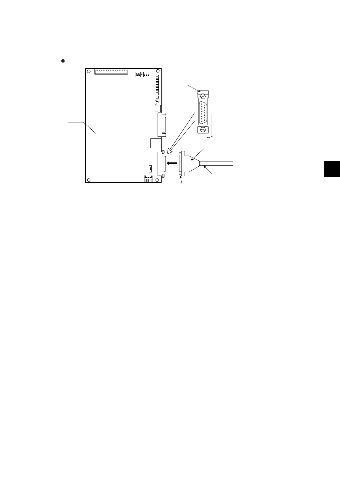
[2] When connecting to a JW-20FLT
Connect a 10BASE-T twisted pair cable to the 10BASE-T connector on the JW-20FLT.
6
10BASE-T twisted
pair cable
10BASE-T connector
6-4
Page 30
[3] Connection of Z-336J
(1) When connecting to a 10BASE5
This paragraph describes how to connect 10BASE5 cable to the Z-336J.
Connecting the transceiver cable
Z-336J
Chapter 6: Connection/Wiring
O
F
F
ON
2
1
SWA
SW1
LN
TX
RX
12V
T
Slide lock
PE
HE
S7
S6
S5
S4
S3
S2
S1
S0
10BASE5 connector
1
↑↓
3
Cable connector
SW6
ON
2
Transceiver cable
Locking post
1 Slide the lock on the 10BASE5 connector (on the Z-336J) up.
2 Insert the connector so that the two locking posts on the cable connector match the holes on
the slide lock.
3 Slide the lock down to lock the cable connector.
6
6-5
Page 31

Chapter 6: Connection/Wiring
Wiring the power source
When a 10BASE5 is used, 12 VDC power should be supplied to the transceiver.
Supply power to the 12 VDC power supply input terminal of the Z-336J using a commercial constant
voltage power supply unit.
Z-336J
6
O
F
F
ON
2
1
SWA
LN
TX
SW1
RX
12V
T
PE
HE
S7
S6
S5
S4
S3
S2
S1
S0
Item Specifications
Supply voltage
Current capacity
12 VDC –5%
0.5 A minimum.
12 VDC power supply input terminal
SW6
ON
Twisted pair wires
Red wire (+)
Green wire
(ground)
Cable
(Accessory: Connector,
cable length 1.5 m)
Black wire (-)
Case
* Fuse (0.6 A)
* Use a fuse that will melt with
time lag
(+)(−)
12 VDC
Remarks
- Use a power supply that is dedicated for use by the Z-336J.
- Do not reverse the positive and negative connections to the power terminals. Reversing the polarity
may damage the Z-336J.
6-6
Page 32

Chapter 6: Connection/Wiring
(2) When connecting to a 10BASE-T
Connect a 10BASE-T twisted pair cable to the 10BASE-T connector on the Z-336J.
O
F
F
ON
2
1
SWA
LN
TX
SW1
RX
12V
T
PE
HE
S7
S6
S5
S4
S3
S2
S1
S0
10BASE-T connector
10BASE-T twisted pair cable
Z-336J
SW6
ON
6
6-7
Page 33

Chapter 6: Connection/Wiring
[4] Connection of JW-50FL
(1) Connection of 10BASE5
This paragraph describes how to connect 10BASE5 cable to the JW-50FL.
Connecting the transceiver cable
6
Locking post
②
①
↑↓
③
10BASE5 connector
Locking post
Transceiver cable
1 Slide the lock on the 10BASE5 connector (on the JW-50FL) up.
2 Insert the connector so that the two locking posts on the cable connector match the holes on
the slide lock.
3 Slide the lock down to lock the cable connector.
Wiring the power source
When a 10BASE5 is used, 12 VDC power should be supplied to the transceiver.
Supply power to the 12 VDC power terminals using a commercial constant voltage power supply
unit.
Slide lock
Item Specifications
Supply voltage
Current capacity
12 VDC –5%
0.5 A minimum.
10B5
Black wire (-)
* Fuse (0.6 A)
10B-T
RESET
(+)
(−)
FG
12VIN
12 VDC
(+)
(−)
* Use a fuse melt with time lag
Red wire (+)
Twisted pair wires
Case
Green wire
(ground)
Cable
(Accessory: Connector, cable length 1.5 m)
Remarks
- Use a power supply that is dedicated for use by the JW-50FL.
- Do not reverse the positive and negative connections to the power terminals. Reversing the
polarity may damage the JW-50FL.
6-8
Page 34

Chapter 6: Connection/Wiring
(2) When connecting to a 10BASE-T
Connect a 10BASE-T twisted pair cable to the 10BASE-T connector on the JW-50FL.
10BASE-T twisted
pair cable
10BASE-T connector
6
6-9
Page 35

Chapter 7: Use Guide
7-1 Ethernet
[1] 10BASE5 system
The basic configuration of a10BASE5 system consists of one coaxial cable, with a maximum length of
500 m, and nodes connected to this cable as shown below. Each node is connected to the coaxial cable
using a transceiver and a transceiver cable (AUI cable). Two types of transceivers are available: Single
port transceivers to connect a single transceiver cable (AUI cable), and multi-port transceivers to connect more than one cable.
This basic configuration unit is referred to as "segment." A maximum of 100 nodes can exist in one
segment.
Chapter 7: Computer Link Function
Max. 500 m
Segment
: Coaxial cable
: Transceiver cable (AUI cable)
: Singe port transceiver
: Multi-port transceiver
Basic connection method for a 10BASE5 system (maximum 500 m without a repeater)
: Node
: Terminator
7
7-1
Page 36

Chapter 7: Computer Link Function
If the distance between nodes is greater than 500 m, connect a repeater as shown below, or to increase
the number of segments by branching. The figure below is an example of a system with a maximum of
1500 m of cable. Arrange the configuration so that there are never more than two repeaters between
any two nodes along any path.
7
Basic connections in a 10BASE5 system (maximum 1500 m using repeaters)
CAUTION
Connect the repeater to the coaxial cable through a transceiver and transceiver cable. Repeaters
can be connected to any transceiver in the same segment. The installation distance between
transceivers is considered to be a multiple of "2.5m" lengths. That is, any cable length should be
evenly divisible by 2.5 m and not have a remainder.
7-2
Page 37

Chapter 7: Computer Link Function
Link segment 1
Link segment 2
Link segment 3
Segment B
Segment A
Segment C
Segment D
: Area inside this
rectangle is treated
as one repeater
The example shown below allows up to 2,500m between nodes. In order to extend communication
distance, link cables are used (with repeaters at both ends). The maximum length of one link is 500
m. These cables are referred to as "link segments."
The link segments must not connect nodes directly. However, the areas surrounded by dotted lines,
including repeaters at both ends, are treated as a single repeater. This does away with the limitation
on the total number of repeaters between nodes in a system.
Basic connections in a 10BASE5 system (maximum 2500 m using repeaters)
CAUTION
Each link segment must be 500 m or less.
Do not connect a node to the link segment.
A link segment is treated as one repeater, even though it includes a repeater at each end (enclosed
with dotted lines).
No more than two repeaters shall exist along the path between any two nodes.
Only one segment in the network can be connected to more than two repeaters.
7
7-3
Page 38

Chapter 7: Computer Link Function
Parameters related to the system configuration are summed up below.
General specifications for configuring an Ethernet system
Maximum length of a segment 500 m
Maximum number of transceivers that can be
installed within one segment
Maximum distance between nodes 2500 m or less (except for the transceiver cables)
Maximum number of nodes in a system 254
Maximum length of transceiver cable (AUI cable) 50 m
Cable length between transceiver and repeater 2 m or less (recommended)
Maximum number of repeaters between two
nodes
[2] 10BASE-T system
Connect a hub to a transceiver using a transceiver cable, and the hub can be connected to multiple
nodes. This system is shown below.
When you want to connect a node to a hub, use twisted pair cable (10BASE-T).
7
Item Specifications
100
2 (However, a link segment is treated as one
repeater, even though it has a repeater at each end.)
: Twisted pair cable
(10BASE-T)
Basic connections in a 10BASE-T system
If distance between the nodes is not too great, you can connect a twisted pair cable to a hub directly,
without using a coaxial cable or transceiver.
7-4
Page 39

Chapter 7: Computer Link Function
[3] IP addresses on an Ethernet
In general, the UDP/IP uses a 32-bit logical address called the "IP address."
The IP address consists of a network address and a host address. Normally, a class C configuration is
used in the FA industry.
Class C 1 1 0 X
IP address classifications on an Ethernet
Each 8 bits of the address are separated by a period and can be expressed as a decimal number. For
example, class C IP addresses are expressed as follows.
11000000
192
Note: The default address in the FL-net address scheme is 192.168.250.N (N: Node numbers 1 to 254).
00000010
Network address
An example of an IP address on a class C Ethernet
Network address
(20 bits)
001.
00000000
000.
Host address
(8 bits)
00000011
003.
Host number
7
7-5
Page 40

Chapter 7: Computer Link Function
7-2 FL-net
[1] Description of the FL-net
(1) The FL-net concept
FL-net is an FA control network that uses an Ethernet protocol.
FL-net has a cyclic transfer function and a message transfer function.
The basic concepts of the FL-net are as follows.
1 Ethernet protocols are used for communication (physically and as conceptual data links)
between FA controllers.
2 A UDP/IP scheme compatible with the Ethernet is used. It establishes the basic data transfer
procedures.
3 While using the basic data transfer methods above, FL-net guarantees data transfer within a
specified time by managing and controlling (preventing conflicts) the access to communications
by each node in the network.
The goal of the FL-net is to control devices such as programmable controllers (PC), robot controllers
(RC), numeric control devices (CNC), and establish an FA control network that allows the exchange of
data between personal computers.
The figure below shows the conceptual arrangement of the FL-net.
7
Image
EWS
Robot
controller
Personal
computer
Gateway
PC
Note: BCR; Bar Code Reader, ID: ID controller
Personal
computer
Nut
runner
Personal
computer
Information network (Ethernet)
FL-net
Printer
NC
Field network
The FL-net concept
Server
BCR
computer
Sensor
actuator
Personal
ID
Graphic
panel
7-6
Page 41

(2) FL-net protocol
The FL-net consists of the following 6 protocol layers.
Application layer Controller interface
Cyclic transfer
FA link protocol layer
Token function
Chapter 7: Computer Link Function
Service function
Message transfer
FL-net
Transport layer UDP
Network layer IP
Data link layer
Physical layer
FA link protocol
Note: The transport layer and network layer use the UDP/IP addressing scheme. The data link layer
and physical layer use the Ethernet scheme.
(3) Features of the FL-net transfer system
The FL-net data transfer system has the following features.
1 It manages the transmission of data using the Master-less Token method, and prevents commu-
nication conflicts.
2 It is possible to specify a certain refresh cycle interval as the FL-net circulates a Token.
3 The specified Token is transmitted together with the cyclic data.
4 When starting up, the FL-net sends a token from the node with the lowest node number.
5 When a token is not received within a certain interval, the next node sends a token.
6 By using the Master-less Token method, even if some nodes are faulty the network will not stop
operating.
7 The FL-net has an information management table for items such as the operation mode (RUN/
STOP) / hardware error (ALARM), so that it can inform other nodes of the operation status.
(Compatible with IEEE802.3)
Ethernet
protocol
7
7-7
Page 42

Chapter 7: Computer Link Function
(4) FL-net's IP address scheme
Each node in the FL-net should be set independently using class C addresses. An "IP address" is an
address used to identify a specific node (station) when sending data and using an Internet Protocol
(IP). Therefore a unique IP address should be assigned to each node or device. The FL-net uses
class C IP addresses.
The default value of an FL-net IP address is "192.168.250.***", where "***" is the node number.
7
FL-net IP
address
Network address
192.168.250 n (n: 1 to 254)
FL-net IP address
Host number
(node number)
[2] The number of modules and their node numbers
Up to 254 nodes can be connected. The FL-net uses node numbers from 1 to 254.
1 Node Nos. 1 to 249: For normal equipment in the FL-net.
2 Node Nos. 250 to 254: For maintenance of the FL-net.
3 Node No. 255: Used internally by the FL-net. The user cannot assign this number. (It is used to
transfer broadcast of the global address.)
4 Node No. 0: Used internally by the FL-net. The user cannot assign this number.
Network
address
Node nbr.
Node number 1 to 249:
Can be used by users.
The number of nodes and node numbers on the FL-net.
Node number 250 to 254:
For maintenance
7-8
Page 43

Chapter 7: Computer Link Function
[3] Data communication type
FL-net data communication supports both "cyclic transfer" and "message transfer."
Cyclic data
with Token
Cyclic transfer
Type of data communication on the FL-net
(1) Cyclic transfer
With cyclic transfer, the JW -50FL sends data at certain intervals. Each node can share data through
a common (shared) memory.
Token Data
Cyclic transfer + Message transfer
Message
data
7
Node
1
Node 1
Node 2
Node 3
Node 4
Node n
Node
2
Node 1
Node 2
Node 3
Node 4
Node n
Example of a common memory and cyclic transfer
Node
3
Node 1
Node 2
Node 3
Node 4
Node n
Node
...
Node 1
Node 2
Node 3
Node 4
Node n
Node
0
Node 1
Node 2
Node 3
Node 4
Node n
Common
memory
7-9
Page 44

Chapter 7: Computer Link Function
(2) Message transfer
In the message transfer operation, the JW-50FL sends data non-cyclically.
Normally, when a request to send occurs, the FL-net will communicate with a certain node.
7
Transfer message from node 1 to 3
123456
[4] Transfer data volume
(1) Cyclic transfer
In a cyclic transfer, the FL-net has an 8 K bits + 8 K words = 8.5 K word transfer area.
The maximum amount of data that can be transferred cyclically at one time by one node is 8.5 K
words.
One word = 2 bytes.
15
2
Transfer message from node 6 to 4
Example of a message transfer
0
2
Area 1
Area 2
8 K bit
Common
memory area
8 K word
Cyclic transfer data limit
7-10
Page 45

Chapter 7: Computer Link Function
(2) Message transfer
The maximum amount of data that can be transferred in one message frame is 1024 bytes (excluding the header section).
Message frame
1024 byes
Message transfer data limit
[5] Transfer cycle
In the cyclic transfer operation, the JW-50FL refreshes the common memory almost constantly. The
JW-50FL controls the transfer of messages so that the refresh interval of the common memory does not
exceed the allowable refresh cycle interval for a single message transfer.
Each node always monitors the messages being transferred throughout the network, waiting to receive
a token addressed to itself. If no message transferred by the network within this cycle, the refresh cycle
interval is increased to 120 % of its current value.
Due to the monitoring process above, the refresh cycle interval is automatically determined by the
number of nodes active on the network.
7
7-11
Page 46

Chapter 7: Computer Link Function
[6] Data area and memory
7
FL-net communication module
Cyclic transfer
Common memory area 1
Common memory area 2
Message transfer
Message transfer
buffer area
FL-net management table area
FL-net parameter area
CPU module
Physical memory
Data area and memory
7-12
Page 47

Chapter 7: Computer Link Function
[7] Communication management table
The status of each node is controlled using an individual node management table (maintained by the
node itself), a participating node management table, and a network management table.
(1) Local node management table
The settings in each local node management table are controlled by the node itself.
Local node management table
Item
Node number 1 byte 1 to 254
Area 1 of common memory: Data top
address
Area 1 of common memory: Data size 2 bytes Size (0 to 0x1ff)
Number
of bytes
2 bytes Word address (0 to 0x1ff)
Description
Area 2 of common memory: Data top
address
Area 2 of common memory: Data size 2 bytes Size (0 to 0x1fff)
Upper layer status 2 bytes RUN/STOP/ALARM/WARNING/NORMAL
Token monitor time 1 byte In units of 1 msec.
Minimum separation of frames 1 byte In units of 100 µsec.
Vendor name 10 bytes Vender name
Manufacturer name 10 bytes Manufacture model name, device name
Node name (facility name) 10 bytes Node name by user entry
Protocol version 1 byte Fixed to 0x80
FA link status 1 byte Participate/leave
Local node's status 1 byte Doubled node number detection, etc.
- "0x1ff" is the hexadecimal notation for 1FF(HEX).
For details about the local node management table maintained by the JW-50FL, see page
10-5.
2 bytes Word address (0 to 0x1fff)
7
7-13
Page 48

Chapter 7: Computer Link Function
(2) Participating node management table
The participating node management table contains data related to the nodes currently participating
in the network.
Participating node management table
7
Item
Node number 1 byte 1 to 254
Upper layer status 2 bytes RUN/STOP/ALARM/WARNING/NORMAL
Area 1 of common memory: Data top
address
Area 1 of common memory: Data size 2 bytes Size (0 to 0x1ff)
Area 2 of common memory: Data top
address
Area 2 of common memory: Data size 2 bytes Size (0 to 0x1fff)
Allowable refresh cycle time 2 bytes In units of 1 msec.
Token monitor time 1 byte In units of 1 msec.
Minimum separation of frames 1 byte In units of 100 µsec.
Link status 1 byte Participate/leave
- "0x1ff" is the hexadecimal notation for 1FF(HEX).
- For details about the participation node management table maintained by the JW-50FL, see
page 10-6.
(3) Network management table
The network management table contains information common to the network.
Number
of bytes
2 bytes Word address (0 to 0x1ff)
2 bytes Word address (0 to 0x1fff)
Description
Network management table
Item
Token latch node number 1 byte Currently token staying node.
Minimum separation of frames 1 byte In units of 100 µsec.
Allowable refresh cycle time 2 bytes In units of 1 msec.
Measured refresh cycle time (current value) 2 bytes In units of 1 msec.
Measured refresh cycle time (maximum value) 2 bytes In units of 1 msec.
Measured refresh cycle time (minimum value) 2 bytes In units of 1 msec.
- For details about the network management table maintained by the JW-50FL, see page 10-6.
Number
of bytes
Description
7-14
Page 49

[8] Cyclic transfer and data area
(1) Outline of the cyclic transfer process
The cyclic transfer process is a function that supports cyclic data exchanges that occur between
nodes.
1 Establishes the common memory function.
2 Transmits when a node receives the token.
3 Nodes which do not execute cyclic transfers within the network are allowed to participate.
4 When received the token, the node sends all the cyclic data that it needs to send.
- Token: Generally, only one token exists in a network. If more than one token exists in a
network, the token with the lowest destination node number has priority and any other token
is discarded.
- Token frame: A frame with a token has a destination node number and a transmitting node
number. The node whose number matches the destination node number holding the token.
- Token order: The token rotation order is determined by the node numbers. The token is
passed to the nodes in order that the nodes were registered in the participating node management table. The node with the highest node number hands the token over to the node
with the lowest node number.
Chapter 7: Computer Link Function
Time
Time
Node #1
Node #1
Node #1
Node #2 Node #3 Node #N
Token
Node #2 Node #3 Node #N
Token
Token rotation and cyclic transfer 1
Node #2
Node #N-1
Token
7
Node #N
Node #1
Node #2
Token
Token rotation and cyclic transfer 2
7-15
Node #N-1
Node #N
Page 50

Chapter 7: Computer Link Function
(2) Common memory
The description of the common memory is as follows.
1 The common memory allows the memory to be shared between nodes performing a cyclic
transfer.
2 Two types of areas (area 1 and area 2) are allocated for each node.
3 If an area needed by a node to send its data exceeds the transfer size allowed for one frame,
namely, more than 1024 bytes, the node should use multiple frames to send the data.
4 When receiving multiple frames of related data, as described in point 3) above, the common
memory does not renew the common memory details until it has received all of the frames
being sent by one node. In other words, it guarantees simultaneity of each node.
(However, if the data in area 2 exceeds 3084 bytes, the JW-50FL cannot guarantee
simultaneity for hardware reasons.)
5 8 K bits + 8 K words = 8.5 K words (fixed) of common memory must be reserved in the node
communication section.
6 The size of areas 1 and 2, used as the sending area for one node in the common memory, can
be specified as any size within the maximum size allowed for the area.
7 Since each node broadcasts data with a certain interval, it provides a function for sharing the
7
same data throughout the system. Each node in an FL-net is assigned a sending area that
does not overlap with the others for exchanging data. In common memory operations, the
sending area for one node will be the receiving area for another node.
Node 01
common memory
(Send)
(Receive)
(Receive)
(Receive)
Node 02
(Receive)
(Send)
(Receive)
(Receive)
Example 1: Common memory during a cyclic transfer
(Receive)
(Receive)
(Receive)
(Send)
Node 04Node 03
(Receive)
(Receive)
(Receive)
(Send)
7-16
Page 51

Chapter 7: Computer Link Function
The common memory can also be used exclusively as a receiving area.
Node 01
common memory
Node 02
Node 05
(Receive)
(Receive) (Send)
Example 2: Common memory during a cyclic transfer
(3) Area 1 and area 2
One node can be allocated two data areas (area 1 and area 2) for common memory. To determine
the sending area, specify a top address and the size of the area.
To access the area, use word addresses. Area 1 consists of 0.5 K word. Area 2 consists of 8 K words.
(Receive)
(Send)
(Receive)
7
Top address
Area 1
Area 2
Top address
Size
Common memory areas 1 and 2
Size
7-17
Page 52

Chapter 7: Computer Link Function
(4) Guarantee of simultaneity
The cyclic transfer divides data into frames, depending on the amount of data being sent.
The FL-net guarantees the simultaneity on common memory of each node using the following procedures.
Note: When area 2 exceeds 3084 bytes, the JW-50FL cannot guarantee the simultaneity
of the data for hardware reasons.
1 Data transmission timing
When a node receives a request to send data from the upper layer, it copies its own cyclic data
into a buffer and sends the data, one word after another. When the amount of data being sent is
more than will fit in one frame, it divides the data in the buffer into multiple frames before
sending.
2 Refresh timing when receiving
After a node has received all the cyclic data from some other node, it will refresh the corresponding area while synchronizing with the upper layer.
When a cyclic data is sent as multiple frames, the receiving node will refresh the area after receiving all the frames from the other node. If any of the frames is missing, it will delete all the data from
that node.
7
Common memory
Data sending side
On network
circuit
Data receiving side
Common memory
Sending
area
Group copy
Data sending buffer
Cyclic data
Cyclic data
Cyclic data
Data receiving buffer
Group copy
Data receive
area
Guarantee of simultaneity of data
7-18
Page 53

[9] Message transfers
(1) Outline of the message transfer process
The message transfer process is a function that allows asynchronous data to be exchanged between nodes.
The basic operation of the message transfer process is shown below.
1 When a node receives a token, it will send a maximum of one frame of message data before
the cyclic frame data sending.
2 A maximum of 1024 bytes can be sent at one time.
3 The JW-50FL uses an algorithm to prevent nodes from exceeding the allowable refresh cycle
interval for message transfers.
4 The JW-50FL has a "1:1" message transfer mode for sending to a specified node, and "1:N"
message transfer mode to send to all nodes.
5 It has a data send confirmation function used to check whether a target node has correctly
received the data in a "1:1" message transfer.
Chapter 7: Computer Link Function
Node 1
Node 1
Request
Request
Response
Node 2 Node 3 Node 4
"1:1" data transfer
Receive
Node 2
Receive
Node 3
"1:N" data transfer
Outline of the message transfer process
7
Receive
Node 4
7-19
Page 54

Chapter 7: Computer Link Function
(2) Table of support messages
Table of support messages
No. Message Request Response Pages to refer
Read byte-block data O O 7-21
1
Write byte-block data O O 7-22
2
Read word-block data O O 7-23
3
Write word-block data O O 7-24
4
Read network parameters O O 7-25
5
Write network parameters O O 7-26
6
Start, stop commands O O 7-27
7
Read profile O O 7-28
8
Read log data O O 7-29
9
Clear log data O O 7-29
0
7
Return message O O 7-30
q
Transfer transmission message O O 7-30
w
7-20
Page 55

(3) Details of the support messages
11
1 Read byte-block data
11
This is a message function used to read a virtual address space (32-bit address space) in a
target node on the network, in units of one byte at a time (each address = 8-bits). Be careful
because the internal address map varies with the FL-net module you are using.
Request message
Response message
Chapter 7: Computer Link Function
8 bits
0
AA
0xffffffff
Virtual address space
7
AA
Physical memory
7-21
Page 56

Chapter 7: Computer Link Function
22
2 Write byte-block data
22
This is a message function used to write to a virtual address space (32-bit address space) in a target
node on the network, in units of one byte at a time (each address = 8-bits). Be careful because the
internal address map varies with the FL-net module you are using.
Request message
Response message
8 bits
0
AA
7
0xffffffff
Virtual address space
AA
Physical memory
7-22
Page 57

Chapter 7: Computer Link Function
33
3 Read word-block data
33
This is a message function used to read a virtual address space (32-bit address space) in a target
node on the network in units of one word at a time (one address = 16-bits). Be careful because the
internal address map varies with the FL-net module you are using.
Request message
Response message
16 bits
0
AAAA
0xffffffff
Virtual address space
AAAA
Physical memory
7
7-23
Page 58

Chapter 7: Computer Link Function
44
4 Write word-block data
44
This is a message function used to write to a virtual address space (32-bit address space) in a target
node on the network in units of one word at a time (one address = 16-bits). Be careful because the
internal address map varies with the FL-net module you are using.
7
Request message
Response message
0
0xffffffff
Virtual address space
16 bits
AAAA
AAAA
Physical memory
7-24
Page 59

Chapter 7: Computer Link Function
5 5
5 Read network parameters
5 5
This is a function used to read the network parameter data for a target node through the network.
It reads the following data.
Network parameter data
- Node number
- Vender name
- Manufacturer model name
- Node name (facility name)
- Address and size of common memory
- Token monitor interval
- Refresh cycle allowable interval
- Refresh cycle measuring interval (actually measured value)
- Minimum allowable distance between frames
- Upper layer status
- FL-net status
- Protocol version
7
Request message
Response message
Node number
Vender name
Manufacturer model name
Node name (facility name)
Top address of area 1
Size of area 1
Top address of area 2
Size of area 2
Token monitor time out time
Minimum allowable distance of frames
FL-net status
Protocol version
Upper layer status
Refresh cycle allowable interval RCT set value
Refresh cycle measured value (current value)
Refresh cycle measured value (maximum value)
Refresh cycle measured value (minimum value)
Network parameter
7-25
Page 60

Chapter 7: Computer Link Function
66
6 Write network parameters
66
This is a function used to change the network parameter data of a receiving node through the
network.
The following data can be changed.
- Node name (facility name)
- Address and size of common memory
When the address and size of the common memory is changed, the receiving node leaves the
network and re-enters it again. If only the node name is changed, the receiving node will not
leave the network.
Request message
Response message
7
Node number
Vender name
Manufacturer model name
Node name (facility name)
Top address of area 1
Size of area 1
Top address of area 2
Size of area 2
Token monitor time out time
Minimum allowable distance of frames
FL-net status
Protocol version
Upper layer status
Refresh cycle allowable interval RTC set value
Refresh cycle measured value (current value)
Refresh cycle measured value (maximum value)
Refresh cycle measured value (minimum value)
Network parameter
7-26
Page 61

Chapter 7: Computer Link Function
77
7 Start, stop commands
77
This is a function used to remotely start and stop the operation of equipment that is connected to the
FL-net.
Request message
Response message
Operation
Operation instruction
Request message
Response message
Stop
Stop instruction
7
7-27
Page 62

Chapter 7: Computer Link Function
88
8 Read profile
88
This is a function used to remotely set the system parameters of a device profile that is the data for
the receiving node. The following parameters are included in the system parameters.
- Common parameters (essential)
- Parameters peculiar to each device (optional)
Request message
Response message
Common parameters
7
Parameters special
to a device
System parameter
7-28
Page 63

99
9 Read log data
99
This is a function used to read the log data of the receiving node.
Request message
Response message
Communication log data
Chapter 7: Computer Link Function
00
0 Clear log data
00
This is a function used to clear log data of the receiving node.
Request message
Response message
7
Clear
Communication log data
7-29
Page 64

Chapter 7: Computer Link Function
qq
q Return message
qq
This is a function used to send back a message that has been received.
The FL-net automatically returns messages.
ww
w Transfer transmission message
ww
This is a function used to provide a transmission service to the FL-net upper layer.
This function informs received message to the FL-net upper layer.
7
The FL-net upper layer supplies this message to the user interface without modification. The user
interface has to create a response and returns against this notice.
Some equipment provides a special service for the transmission message. For details, check the
services on each device.
Request message
Response message
Request message
Response message
FL-net
upper layer
User interface
Create
response
message
7-30
Page 65

Chapter 8: Cyclic Transfer
Chapter 8: Cyclic Transfer
To execute a cyclic transfer using the FL-net module (JW-20FL5/20FLT and JW-50FL) and FL-net
board (Z-336J), the parameters in the common memory areas (area 1 and 2) must be set.
Token Data
Common
memory
area
Area 1
Area 2
Capacity
Common
memory area
Node
1
Node 1
Node f
Node n
Node 1
Node f
Node n
Area 1 8K bits (8192 bits = 1024 bytes)
Area 2 8K words (8192 words = 16384 bytes)
Own
node
(node f)
Node 1
Node f
Node n
Node 1
Node f
Node n
1
2
3
4
5
6
Node
n
Node 1
Node f
Node n
Node 1
Node f
Node n
f = 1 to n (n:1 to 249)
8.5K words
8
- Nodes used to execute a cyclic transfer must have 8.5 K words of memory available for the
common memory area.
- Areas that can be allocated as the common memory area Page 8-4 to 8-6.
- Notes on the common memory areas Next page.
Parameter items to set
Set item
Top address and file number on a PC
Area 1
Area 2
- Set the parameters for use by the module in controlling any module (CPU board) installed in
this module. See "Chapter 12: Parameters."
Top address of sending area (this node)
Sending data length (this node)
Top address and file number on a PC
Top address of sending area (this node)
Sending data length (this node)
Reference number
of the figure above
1
2
3
4
5
6
Parameter
address(8)
20 to 22
10 to 11
12 to 13
24 to 26
14 to 15
16 to 17
8-1
Page 66

Chapter 8: Cyclic Transfer
Notes on the common memory areas
The common memory areas (area 1 and 2) can also be set using the following procedures.
1. There is no need to allocate sequential node numbers.
[Example]
8
Node
2
Node 2
Area 1
2. There is no need to assign data memory areas in node number order.
[Example]
Area 1
3. There is no need for continuous data memory areas.
[Example]
Node 4
Node 7
Node
1
Node 1
Node 4
Node 3
Node 2
Node
1
Node
4
Node 2
Node 4
Node 7
Node
2
Node 1
Node 4
Node 3
Node 2
Node
2
Node
7
Node 2
Node 4
Node 7
Node
3
Node 1
Node 4
Node 3
Node 2
Node
3
Node
4
Node 1
Node 4
Node 3
Node 2
Area 1
Node 1
Node 2
Node 3
Node 1
Node 2
Node 3
Node 1
Node 2
Node 3
8-2
Page 67

Chapter 8: Cyclic Transfer
8-1 Setting procedures
This section describes all of the FL-net module setting procedures. For details about message transfers,
the communication management area, and the SEND/RECEIVE function, see the respective chapters.
1 1
1 Specify a parameter area See Chapter 12.
1 1
A parameter area is allocated within the control module.
- When the JW20H, JW30H, or J-board is used for a PC, set the parameter area in accordance
with the set value of the module No. switch.
- When the JW50H/70H/100H is used for host PC, set switch SW3 on the JW-50FL.
22
2 Enter basic data
22
Enter basic data (node number, token monitor interval, and minimum separation of frames) in the
parameter area (addresses 00 to 05(8)).
33
3 Settings related to cyclic transfers
33
1) Enter the top address for the common memory areas (area 1 and 2)
- The data memory area (see pages 8-4 to 8-6) in which a common memory area can be
assigned in the PC varies with the model of the module installed in the PC.
- Enter the top addresses for area 1 and area 2 at parameter addresses 20 to 26(8) as word
addresses (see pages 8-7 to 8-12).
2) Enter the send area address for this node
- Enter the send area parameters for this node (top address and data length) for areas 1 and
2 at addresses 10 to 17(8). Enter a word address (page 8-7 to 8-12) for the top address.
44
4 Settings related to message transfers See Chapter 9 (page 9-2).
44
When you will not be using the client function in the messages that are sent, this setting is not
required.
1) Set the buffer area for transmitted messages
Enter the top address of the transmission buffer, and this area (address +0000 to 4055(8):
2094 bytes) will also be set. Enter the top address at parameter addresses 34 to 36(8).
2) Enable use of the transmission buffer
Enable/disable the use of this buffer for each message. Use parameter address 37(8).
55
5 Assign the communication management area See Chapter 10 (page 10-1).
55
Enter the top address of the communication management area, and the areas (address +000 to
301(8): 194 bytes) will also be set. Enter the top address at parameter addresses 20 to 26(8).
66
6 Enter the node name
66
Enter the node name at parameter addresses 40 to 51(8), if required.
8
77
7 Enter a SEND/RECEIVE instruction time-out time See Chapter 11.
77
When using the SEND/RECEIVE function, enter a time-out time (0.1 to 25.5 seconds) at param
eter address 60(8). If you will not be using the SEND/RECEIVE function, this setting is not required.
88
8 Set the start switch
88
Change the value at parameter address 77(8) from 00(H) to 01(H), and transfer the parameter
setting details from the control module (CPU board) to the FL-net module, to start communication.
8-3
Page 68

Chapter 8: Cyclic Transfer
8-2 Areas that can be allocated as the common memory area
The data memory area that can be allocated as the common memory areas (area 1 and 2) vary with the
model of the module used.
FL-net module Host PC Control module Details
JW20H JW-21CU/22CU See below
JW-20FL5
JW-20FLT
FL-net board Host J-board CPU board Details
Z-336J
FL-net module Host PC Memory module Details
JW30H
Z-300 series Z-311J/312J/313J See below
Z-500 series Z-511J Next page
JW50H ---
JW-31CUH1
Next pageJW-32CUH1
JW-33CUH1/2/3
JW-1MAH
8
JW-50FL
(1) For the JW20H or J-board (Z-300 series)
Relay 00000 to 15777
TMR/CNT contact point T-C000 to T-0777
TMR/CNT/MD current value --- b0000 to b1777 002000 to 003777
Register ---
Self diagnosis result
storage register
JW70H
JW100H
Address of the data memory that can be allocated to common memory
Bit address
JW-2MAH
JW-3MAH
JW-4MAH
(8)
--- E0000 to E1777 016000 to 017777
Page 8-6
Byte address
コ 0000 to コ 1577
コ 1600 to コ 1777
09000 to 09777 004000 to 004777
19000 to 19777 005000 to 005777
29000 to 29777 006000 to 006777
39000 to 39777 007000 to 007777
49000 to 49777 010000 to 010777
59000 to 59777 011000 to 011777
69000 to 69777 012000 to 012777
79000 to 79777 013000 to 013777
89000 to 89777 014000 to 014777
99000 to 99777 015000 to 015777
(8)
File address
000000 to 001577
001600 to 001777
(8)
- The top address parameter is a word based address. See page 8-8.
8-4
Page 69

(2) For the JW30H or J-board (Z-500 series)
Chapter 8: Cyclic Transfer
Address of the data memory that can be allocated to
common memory
Bit address(8) Byte address(8) File address(8)
File 0
Relay 00000 to 15777
TMR/CNT contact point T-C0000 to T-C0777
TMR/CNT/MD current value --- b0000 to b1777 002000 to 003777
Register ---
Register
(Possible to register error history)
TMR/CNT current value --- b2000 to b3777 026000 to 027777
Expansion relay 20000 to 75777
TMR/CNT contact point T-C1000 to T-C1777
File 1 --- --- 000000 to 037777
File 2 --- --- 000000 to 177777
File 3 --- --- 000000 to 177777
File 10
(H) --- --- 000000 to 177777
to
File 14
(H) --- --- 000000 to 177777
to to to to
(H) --- --- 000000 to 177777
File 2C
--- E6000 to E7777 024000 to 025777
to to to
コ 0000 to コ 1577
コ 1600 to コ 1777
09000 to 09777 004000 to 004777
19000 to 19777 005000 to 005777
29000 to 29777 006000 to 006777
39000 to 39777 007000 to 007777
49000 to 49777 010000 to 010777
59000 to 59777 011000 to 011777
69000 to 69777 012000 to 012777
79000 to 79777 013000 to 013777
89000 to 89777 014000 to 014777
99000 to 99777 015000 to 015777
E0000 to E5777 016000 to 023777
コ 2000 to コ 7577
コ 7600 to コ 7777
000000 to 001577
001600 to 001777
030000 to 035577
035600 to 035777
8
- The relationship between the control module (on which the memory module is installed) and the file
memory is as follows.
Control module File memory
JW-31CUH1 File 0
JW-32CUH1 *
File 0, 1, and 2
(File 2 can be allocated to 000000 to 177777 or 000000 to 077777)
JW-33CUH1 File 0, 1 to 3
JW-33CUH2 File 0, 1 to 3 and 10 to 14
(H)
JW-33CUH3 File 0, 1 to 3 and 10 to 2C(H)
* File memory of J-board (Z-500 series) is the same as that of JW-32CUH1.
- The top address parameter is a word based address. See page 8-9.
8-5
Page 70

Chapter 8: Cyclic Transfer
(3) For the JW50H/70H/100H
Address of the data memory that can be allocated to
common memory
8
Bit address
Relay 00000 to 15777
T-C0000 to 0777
TMR/CNT contact point
T-C1000 to 1777
(8)
Byte address
(8)
コ 0000 to コ 1577
コ 1600 to コ 1777
コ 1300 to コ 1477*
File address
000000 to 001577
001600 to 001777
001300 to 001477 *
TMR/CNT/MD current value --- b0000 to b1777 002000 to 003777
09000 to 09777 004000 to 004777
19000 to 19777 005000 to 005777
29000 to 29777 006000 to 006777
File 0
39000 to 39777 007000 to 007777
49000 to 49777 010000 to 010777
59000 to 59777 011000 to 011777
Register ---
69000 to 69777 012000 to 012777
79000 to 79777 013000 to 013777
89000 to 89777 014000 to 014777
99000 to 99777 015000 to 015777
E0000 to E0777 016000 to 016777
E1000 to E1777 017000 to 017777
File 1 --- --- 000000 to 177777
File 2 --- --- 000000 to 177777
File 3 --- --- 000000 to 177777
to
to to to
File 7 --- --- 000000 to 177777
* コ1300 to コ1477 (file addresses 001300 to 001477) are for shared use with the general-purpose
relays. Therefore, if a timer/counter is set up with 1024 points, these file addresses cannot be used
for the general-purpose relays.
(8)
- The relationship between the PC model (on which the memory module is installed) and the file
memory is as follows.
PC model
Integrated memory
module
File memory
JW50H --- File 0, 1 (000000 to 037777)
JW-1MAH File 0, 1 (000000 to 037777)
JW70H
JW100H
JW-2MAH File 0, 1 (000000 to 177777)
JW-3MAH File 0, 1, 2
JW-4MAH File 1 to 7
- The top address parameter is a word based address. See page 8-11.
8-6
Page 71

8-3 Parameter settings for cyclic transfers
The parameters related to cyclic transfers are as follows.
Parameter
address
(8)
Description
Chapter 8: Cyclic Transfer
10
2
11
12
3
5
6
1
4
13
14
15
16
17
20
21
22 File number of area 1 on the PC.
24
25
26 File number of area 2 on the PC.
Corresponds to 1 to 6 on page 8-1. (For parameter details See Chapter 12.)
Top address (word address) of the data sending areas of own node area 1 *
- Address 10 is for the lower digit and 11 is for the upper digit.
Sending data length (word) of own node area 1
- Address 12 is for the lower digit and 13 is for the upper digit.
Top address (word address) of the data sending areas of own node area 1 *
- Address 14 is for the lower digit and 15 is for the upper digit.
Sending data length (word) of own node area 1
- Address 16 is for the lower digit and 17 is for the upper digit.
Top address (word address) of area 1 on a PC *
- Address 20 is for the lower digit and 21 is for the upper digit.
Top address (word address) of area 2 on a PC *
- Address 24 is for the lower digit and 25 is for the upper digit.
8
- Enter the top address in word units (* above). Pages 8-8 to 8-12.
Ex.: Enter コ1600 to コ1601 (word address 01C0(H)) as the top address at parameter addresses 10
and 11(8).
Parameter address (Upper digit) 11 (Lower digit) 10
Set value (HEX) 01 C0
8-7
Page 72

Chapter 8: Cyclic Transfer
[1] Word addresses used for the top address
The top address entered in the parameters for cyclic transfers on the FL-net are word addresses.
Variations among the PLC models that can be installed are shown below.
(1) For the JW20H or J-board (Z-300 series)
Relay
TMR/CNT contact point
TMR/CNT/MD current value
8
Register
Self diagnosis result
storage register
JW20H/J-board (Z-300series) address Top address set in FL-net cyclic transfer
Byte address
コ 0000, コ 0001
コ 0002, コ 0003
コ 1576, コ 1577
コ 1600, コ 1601
コ 1602, コ 1603
コ 1776, コ 1777
b0000, b0001 002000, 002001 001000 0200
b0002, b0003 002002, 002003 001001 0201
b1776, b1777 003776, 003777 001777 03FF
09000, 09001 004000, 004001 002000 0400
09002, 09003 004002, 004003 002001 0401
09776, 09777 004776, 004777 002377 04FF
19000, 19001 005000, 005001 002400 0500
19776, 19777 005776, 005777 002777 05FF
29000, 29001 006000, 006001 003000 0600
29776, 29777 006776, 006777 003377 06FF
39000, 39001 007000, 007001 003400 0700
39776, 39777 007776, 007777 003777 07FF
49000, 49001 010000, 010001 004000 0800
49776, 49777 010776, 010777 004377 08FF
59000, 59001 011000, 011001 004400 0900
59776, 59777 011776, 011777 004777 09FF
69000, 69001 012000, 012001 005000 0A00
69776, 69777 012776, 012777 005377 0AFF
79000, 79001 013000, 013001 005400 0B00
79776, 79777 013776, 013777 005777 0BFF
89000, 89001 014000, 014001 006000 0C00
89776, 89777 014776, 014777 006377 0CFF
99000, 99001 015000, 015001 006400 0D00
99776, 99777 015776, 015777 006777 0DFF
E0000, E0001 016000, 016001 007000 0E00
E1776, E1777 017776, 017777 007777 0FFF
(8)
File address
000000, 000001 000000 0000
000002, 000003 000001 0001
to to to to
001576, 001577 000677 01BF
001600, 001601 000700 01C0
001602, 001603 000701 01C1
to to to to
001776, 001777 000777 01FF
to to to to
to to to to
to to to to
to to to to
to to to to
to to to to
to to to to
to to to to
to to to to
to to to to
to to to to
to to to to
(8)
Word unit: Octal Word unit: Hex.
8-8
Page 73

(2) For the JW30H or J-board (Z-500 series)
JW30H/J-board (Z-500 series)
address
Relay
TMR/CNT contact point
TMR/CNT/MD current value
File 0
Register
Byte address
コ 0000, コ 0001
コ 0002, コ 0003
コ 1576, コ 1577
コ 1600, コ 1601
コ 1602, コ 1603
コ 1776, コ 1777
b0000, b0001 002000, 002001 001000 0200
b0002, b0003 002002, 002003 001001 0201
b1776, b1777 003776, 003777 001777 03FF
09000, 09001 004000, 004001 002000 0400
09002, 09003 004002, 004003 002001 0401
09776, 09777 004776, 004777 002377 04FF
19000, 19001 005000, 005001 002400 0500
19776, 19777 005776, 005777 002777 05FF
29000, 29001 006000, 006001 003000 0600
29776, 29777 006776, 006777 003377 06FF
39000, 39001 007000, 007001 003400 0700
39776, 39777 007776, 007777 003777 07FF
49000, 49001 010000, 010001 004000 0800
49776, 49777 010776, 010777 004377 08FF
59000, 59001 011000, 011001 004400 0900
59776, 59777 011776, 011777 004777 09FF
69000, 69001 012000, 012001 005000 0A00
69776, 69777 012776, 012777 005377 0AFF
79000, 79001 013000, 013001 005400 0B00
79776, 79777 013776, 013777 005777 0BFF
89000, 89001 014000, 014001 006000 0C00
89776, 89777 014776, 014777 006377 0CFF
99000, 99001 015000, 015001 006400 0D00
99776, 99777 015776, 015777 006777 0DFF
E0000, E0001 016000, 016001 007000 0E00
E5776, E5777 023776, 023777 011777 13FF
(8)
000000, 000001 000000 0000
000002, 000003 000001 0001
to to to to
001576, 001577 000677 01BF
001600, 001601 000700 01C0
001602, 001603 000701 01C1
to to to to
001776, 001777 000777 01FF
to to to to
to to to to
to to to to
to to to to
to to to to
to to to to
to to to to
to to to to
to to to to
to to to to
to to to to
to to to to
File address
Top address set in FL-net cyclic
transfer
(8)
Word unit: Octal Word unit: Hex.
Chapter 8: Cyclic Transfer
8
Continued on the next page
8-9
Page 74

Chapter 8: Cyclic Transfer
From the previous page
8
Register
(Possible to register
error history)
TMR/CNT/MD current value
File 0
Expansion relay
TMR/CNT contact point
File 1 ---
File 2 ---
File 3 ---
File 10
to to to to to
File 14
to to to to to
File 2C
JW30H/J-board (Z-500 series)
address
Byte address
E6000, E6001 024000, 024001 012000 1400
E7776, E7777 025776, 025777 012777 15FF
b2000, b2001 026000, 026001 013000 1600
b3776, b3777 027776, 027777 013777 17FF
コ 2000, コ 2001
コ 7576, コ 7577
コ 7600, コ 7601
コ 7776, コ 7777
(H)
(H)
(H)
(8)
File address
to to to to
to to to to
030000, 030001 014000 1800
to to to to
035576, 035577 016677 1DBF
035600, 035601 016700 1DC0
to to to to
035776, 035777 016777 1DFF
000000, 000001 000000 0000
to to to
037776, 037777 017777 1FFF
000000, 000001 000000 0000
to to to
177776, 177777 077777 7FFF
000000, 000001 000000 0000
to to to
177776, 177777 077777 7FFF
000000, 000001 000000 0000
---
---
---
to to to
177776, 177777 077777 7FFF
000000, 000001 000000 0000
to to to
177776, 177777 077777 7FFF
000000, 000001 000000 0000
to to to
177776, 177777 077777 7FFF
Top address set in FL-net cyclic
transfer
(8)
Word unit: Octal Word unit: Hex.
- The relationship between the control module (on which the memory module is installed) and file
memory is as follows.
Control module File memory
JW-31CUH1 File 0
JW-32CUH1 *
File 0, 1, and 2
(File 2 can be allocated to 000000 to 177777 or 000000 to 077777)
JW-33CUH1 File 0, 1 to 3
JW-33CUH2 File 0, 1 to 3 and 10 to 14
(H)
JW-33CUH3 File 0, 1 to 3 and 10 to 2C(H)
* File memory of J-board (Z-500 series) is the same as that of JW-32CUH1.
8-10
Page 75

(3) For the JW50H/70H/100H
Relay
TMR/CNT contact point *
TMR/CNT/MD current value
Register
Continued on the next page
Chapter 8: Cyclic Transfer
JW30H/J-board (Z-500 series)
address
Byte address
コ 0000, コ 0001
コ 0002, コ 0003
コ 1576, コ 1577
コ 1600, コ 1601
コ 1602, コ 1603
コ 1776, コ 1777
b0000, b0001 002000, 002001 001000 0200
b0002, b0003 002002, 002003 001001 0201
b1776, b1777 003776, 003777 001777 03FF
09000, 09001 004000, 004001 002000 0400
09002, 09003 004002, 004003 002001 0401
09776, 09777 004776, 004777 002377 04FF
19000, 19001 005000, 005001 002400 0500
19776, 19777 005776, 005777 002777 05FF
29000, 29001 006000, 006001 003000 0600
29776, 29777 006776, 006777 003377 06FF
39000, 39001 007000, 007001 003400 0700
39776, 39777 007776, 007777 003777 07FF
49000, 49001 010000, 010001 004000 0800
49776, 49777 010776, 010777 004377 08FF
59000, 59001 011000, 011001 004400 0900
59776, 59777 011776, 011777 004777 09FF
69000, 69001 012000, 012001 005000 0A00
69776, 69777 012776, 012777 005377 0AFF
79000, 79001 013000, 013001 005400 0B00
79776, 79777 013776, 013777 005777 0BFF
89000, 89001 014000, 014001 006000 0C00
89776, 89777 014776, 014777 006377 0CFF
99000, 99001 015000, 015001 006400 0D00
99776, 99777 015776, 015777 006777 0DFF
E0000, E0001 016000, 016001 007000 0E00
E1776, E1777 017776, 017777 007777 0FFF
(8)
File address
000000, 000001 000000 0000
000002, 000003 000001 0001
to to to to
001576, 001577 000677 01BF
001600, 001601 000700 01C0
001602, 001603 000701 01C1
to to to to
001776, 001777 000777 01FF
to to to to
to to to to
to to to to
to to to to
to to to to
to to to to
to to to to
to to to to
to to to to
to to to to
to to to to
to to to to
Top address set in FL-net cyclic
transfer
(8)
Word unit: Octal Word unit: Hex.
* To address T-C1000 to 1777, which are TMR/CNT contact points,
use コ1300 to コ1477 (file addresses 001300 to 001477) in the general-purpose relays.
8
8-11
Page 76

Chapter 8: Cyclic Transfer
From the previous page
JW50H/70H/100H address Top address set in FL-net cyclic transfer
8
Byte address
(8)
File address
(8)
Word unit: Octal Word unit: Hex.
000000, 000001 000000 0000
to to to
File 1
037776, 037777 017777 1FFF
to to to
177776, 177777 077777 7FFF
000000, 000001 000000 0000
File 2
to to to
177776, 177777 077777 7FFF
000000, 000001 000000 0000
File 3
to to to
177776, 177777 077777 7FFF
to to to to to
000000, 000001 000000 0000
File 7
to to to
177776, 177777 077777 7FFF
- The relationship between the PC model, the memory module that is installed, and file memory is as
follows.
PC model Integrated memory module File memory
JW50H --- File 0, 1 (000000 to 037777)
JW-1MAH File 0, 1 (000000 to 037777)
JW70H
JW100H
JW-2MAH File 0, 1 (000000 to 177777)
JW-3MAH File 0, 1, 2
JW-4MAH File 1 to 7
8-12
Page 77

8-4 Communication time
[1] Token round time
The token round time can be obtained as follows.
Node N−1 Node N
△Tn
Spacing between data
of this node and the
previous node
Chapter 8: Cyclic Transfer
Token round time = ∑ △Tn
(Total of the space (time) between data from this node and all previous nodes.)
"Tn" varies with the amount of data sent by the previous station. It also varies with the processing timing
of the JW-50FL. To get the token round time, perform a calculation based on the rough numbers shown
below.
Cyclic transfer capacity per station (word)
Area 1 Area 2
16 256 2.2 to 3.0
32 464 3.0 to 4.2
32 512 3.6 to 4.3
64 960 4.2 to 6.1
64 1024 5.0 to 6.7
96 1440 5.1 to 8.1
96 1536 6.5 to 9.0
128 1920 6.8 to 10.1
128 2048 8.0 to 10.6
160 2560 8.6 to 13.3
256 4096 13.9 to 18.4
- The values above are for the JW-50FL. For other nodes, see each manual.
m
n=1
Communication time
per station (ms)
111.2 to 1.7
221.3 to 1.7
4641.5 to 1.9
8 128 1.7 to 2.3
8
When message transfers are used, the communication time will be longer. However, the FL-net restricts the token round time when using message transfers to 1.2 times that of a message transfer.
[2] Round time when a communication error occurs
If a station goes down, the node immediately after the dead node will issue a token. This time depends
on the token monitor time of the dead node. Therefore, if one station goes down, its cycle will result in a
longer token monitor time than the dead node would have used. If two consecutive nodes go down
simultaneously, the next node will issue a token. In this case the time required to issue a new token will
be the total of the token monitor time of both dead nodes. If more than two consecutive nodes go down,
a similar calculation will apply.
8-13
Page 78

Chapter 9: Message transfers
Chapter 9: Message Transfers
The message transfer method used with the module classifies messages as "client function," "transmission
type message," or "remote function" (SHARP's proprietary function). These classifications can be assigned
by setting each type to "Used" or "Not used," as shown below.
Message transfer
of the module
*1
Client function
Use
Do not use
Message
Transmission
message
Use
Do not use
Use
Do not use
*2
Remote function (SHARP’s
proprietary function)
Use
Do not use
81
83
81
Use
Do not use
80
82
00
Selection of
transmission buffer
80
(H)81(H)82(H)83(H)
(H)
(H)
(H)
(H)
(H)
(H)
*3
Message other than transmission
Messages other than SHARP's proprietary
Transmission
message
message format
SHARP's
proprietary format
Computer link function
Remote function
×○ ×○
○○○○
○○○○
○○ ××
O: Usable X: Not usable
*1: The client function is used to send a message to a target node and receive a response from that
node. When not sending a transmission message, set the client function to "Not used."
*2: The remote function includes the remote programming and remote monitoring functions.
*3: 00, and 80 to 83(H) are values used for the parameter address 37(8). See Chapter 12.
To execute a message transfer using the FL-net, the following settings are required on the control module
(CPU board) of the PC on which the FL-net is installed.
1 Create a transmission buffer area for the parameters and select it for use.
2 Place the message to send in the transmission buffer.
3 Execute a send command in the communication control area.
Send data (request)
FL-net
This node
(Host PC
for the
module)
Receive data (response)
Node
used to
exchange
data
9
■ Inside the control module (CPU board) of the PC
Address(8)
Parameter
30
Set up the communication
control area
33
Set up a transmission
34
buffer
37
Start switch
77
- Parameters => See Chapter 12
Address(8)
+0000
+1777
+2000
+3777
+4000
+4015
+4040
+4050
Transmission buffer
Received data
(data section)
Transmitted data
(data section)
Received data
(information section)
Transmitted data
(information section)
9-1
Communication
*1
+000
+301
Enter the details for
the messages to be
sent
*1: Enter the top address at
parameter addresses 34 to 36.
control area
*2
Execute a send
data command
*2: Enter the top address at
parameter addresses 30 to 32.
Page 79

Chapter 9: Message transfers
9-1 Message sending procedures and data reception details
This section describes procedures used for the settings needed to send (or request) messages using
the message transfer function, as well as the details for receiving data from a node. (JW-50FL general
setting procedures See page 8-3.)
Send data (request)
9
FL-net
11
1 Setting the parameters
11
This node
(Host PC
for the JW50FL
Receive data (response)
Node
used to
exchange
data
Specify the transmission buffer area that will be used to send (request) and receive (response)
messages.
1) Specify the area for the transmission buffer
When the top address of the transmission buffer has been entered, the area (address +
0000 to 4055(8): 2094 bytes) will be allocated. Enter the top address at parameter address
(34 to 36(8)).
Parameter
address
(8)
34
35
Top address (word address) of transmission buffer
- Address 34 is for the lower digit. Address 35 is for the upper digit.
Details
36 File number of the transmission buffer
(Parameter details See Chapter 12.)
2) Set the transmission buffer to "Used"
Select whether or not to enable each message classification. Enter your choices at
parameter address 37(8).
Parameter
address
(8)
Details
37 Enable/disable use of a transmission type buffer
Setting value
Message
80
Message other than transmission
Messages other than SHARP's proprietary
Transmission
message
message format
SHARP's
proprietary format
Computer link function
Remote function
(H)81(H)
×○ ×○
○○○○
○○○○
○○ ××
82
(H)83(H)
O: Used X: Not used
3) Set the start switch
Change the parameter setting at address 77(8) from 00(H) to 01(H), and transfer the setting
details for the control module to the JW-50FL.
To the next page
Parameter address
77 Start switch
(8)
Detail
9-2
Page 80

From the previous page
22
2 Setting transmission buffer (set the sending details)
22
Specify the [information section] and [data section] to be used for sending messages to the
transmission buffer (addresses +2000 to 3777(8), +4040 to 4055(8)).
Transmission
buffer address
+2000
to
+3777
+4040 Node number of destination node.
+4041 Response message type (fixed to 00
+4042 to 4043 Message (request) transaction code.
+4044 to 4047 Top address of the virtual address space.
+4050 to 4051
+4052 Current fragment block number (fixed to 01
+4053 Total fragment block number (fixed to 01
+4054 to 4055 Current block length (byte)
(8)
Sending [data section]
Data length requesting to the virtual address
space (word/byte).
Details
(H)
Chapter 9: Message transfers
)
Sending
[information section]
(H)
)
(H)
)
(Transmission buffer Next page.)
33
3 Execute a transmission
33
Write an 01(H) at address +301 in the communication control area and the JW-50FL will send the
contents of the transmission buffer [information section] and [data section] to the destination
node. After sending the message, the details in the [data section] will be cleared.
Communication
control address
+301 Execute sending data
(8)
Detail
(Communication control area See page 10-1.)
Settings in the communication control area
Enter the top address for the communication control area. The area (address +000 to 301(8)) will
then be allocated. Use the parameter addresses 30 to 32(8) to enter the top address.
When receive data
44
4 Receive (received to transmission buffer)
44
The received data from a node are stored in the transmission buffer (address +0000 to 1777(8),
+4000 to 40015(8)).
Transmission
buffer address
(8)
Details
+0000
to
Receiving [data section]
9
+1777
+4000 Node number of data sending node.
+4001 Response message type (fixed to 00
(H)
)
+4002 to 4003 Message (response) transaction code.
+4004 to 4007 Top address of the virtual address space.
+4010 to 4011
Data length requesting to the virtual address
space (word/byte).
+4012 Current fragment block number (fixed to 01
+4013 Total fragment block number (fixed to 01
(H)
+4014 to 4015 Current block length (byte)
9-3
Sending
[information section]
(H)
)
)
Page 81

Chapter 9: Message transfers
9-2 Transmission buffer
This section describes the transmission buffer that is used for sending and receiving data for the
message transfer.
The transmission buffer area (+0000 to 4055(8)) is determined by entering top address to parameter
(address 34 to 36(8)). (Parameter See Chapter 12.)
9
Transmission
buffer address
+0000
to
+1777
(8)
Receiving [data section]
- When writing 00
(H)
to address +4000, the received data will be
transferred to the control module (CPU board)
Details
+2000
to
Sending [data section] *
1
+3777
+4000 Node number of the node sending data.
+4001 Response message type (always 00
(H)
)
+4002 to 4003 Transaction code (response).
+4004 to 4007 Top address of the virtual address space.
+4010 to 4011
Data length of response from the virtual
address space (word/byte).
+4012 Current fragment block number (always 01
+4013 Total fragment block number (always 01
(H)
+4014 to 4015 Current block length (byte)
+4016 to 4037 Reserved area
+4040 Node number of destination node. *
2
Receiving
[information section]
(H)
)
)
+4041 Response message type (always 00
(H)
)
+4042 to 4043 Transaction code (request).
+4044 to 4047 Top address of the virtual address space.
+4050 to 4051
Data length requesting to the virtual address
space (word/byte).
+4052 Current fragment block number (always 01
+4053 Total fragment block number (always 01
(H)
)
(H)
)
*1 Sending
[information section]
+4054 to 4055 Current block length (byte)
*1: The data in the transmission area [information section] and [data section] are transferred when
01(H) is written at the base address +301 in the communication control area. After sending data,
JW-50FL clears the setting data of the sending data section.
*2: Enter 255(D) at the base address +4040. Then the data will be transferred to all the nodes
currently connected.
9-4
Page 82

Chapter 9: Message transfers
[1] Allocation of available areas for the transmission buffer
The allocation of available areas for the transmission buffer varies with the module on which the FL-net
is installed.
FL-net module Host PC Control module Details
JW20H JW-21CU/22CU See below
JW-20FL5
JW-20FLT
JW30H
FL-net board Host J-board CPU board Details
Z-336J
Z-300 series Z-311J/312J/313J See below
Z-500 series Z-511J Next page
FL-net module Host PC Memory module Details
JW50H ---
JW-50FL
JW70H
JW100H
JW-31CUH1
JW-33CUH1/2/3
JW-1MAH
JW-2MAH
JW-3MAH
JW-4MAH
Next pageJW-32CUH1
Page 9-7
(1) For the JW20H or J-board (Z-300 series)
Allocation available data memory address
for the transmission buffer
Bit address
Relay 00000 to 15777
TMR/CNT contact point T-C000 to T-C777
(8)
Byte address
コ 0000 to コ 1577
コ 1600 to コ 1777
(8)
File address
000000 to 001577
001600 to 001777
TMR/CNT current value --- b0000 to b1777 002000 to 003777
09000 to 09777 004000 to 004777
19000 to 19777 005000 to 005777
29000 to 29777 006000 to 006777
39000 to 39777 007000 to 007777
49000 to 49777 010000 to 010777
Register ---
59000 to 59777 011000 to 011777
69000 to 69777 012000 to 012777
79000 to 79777 013000 to 013777
89000 to 89777 014000 to 014777
99000 to 99777 015000 to 015777
Self diagnosis result
storage register
--- E0000 to E1777 016000 to 017777
(8)
9
Note: Be careful not to allow the transmission buffer area to overlap with the common memory area.
9-5
Page 83

Chapter 9: Message transfers
(2) For the JW30H or J-board (Z-500 series)
Allocation available data memory address
for the transmission buffer
9
File 0
Bit address
Relay 00000 to 15777
TMR/CNT contact point T-C0000 to T-C0777
(8)
Byte address
コ 0000 to コ 1577
コ 1600 to コ 1777
(8)
File address
000000 to 001577
001600 to 001777
TMR/CNT/MD current value --- b0000 to b1777 002000 to 003777
09000 to 09777 004000 to 004777
19000 to 19777 005000 to 005777
29000 to 29777 006000 to 006777
39000 to 39777 007000 to 007777
49000 to 49777 010000 to 010777
Register ---
59000 to 59777 011000 to 011777
69000 to 69777 012000 to 012777
79000 to 79777 013000 to 013777
89000 to 89777 014000 to 014777
99000 to 99777 015000 to 015777
E0000 to E5777 016000 to 023777
Register
(Possible to register error history)
--- E6000 to E7777 024000 to 025777
TMR/CNT current value --- b2000 to b3777 026000 to 027777
Expansion relay 20000 to 75777
TMR/CNT contact point T-C1000 to T-C1777
コ 2000 to コ 7577
コ 7600 to コ 7777
030000 to 035577
035600 to 035777
File 1 --- --- 000000 to 037777
File 2 --- --- 000000 to 177777
File 3 --- --- 000000 to 177777
File 10
to
File 14
(H)
(H)
--- --- 000000 to 177777
to to to
--- --- 000000 to 177777
(8)
to to to to
File 2C
(H)
--- --- 000000 to 177777
- The relationship between the control module (on which the memory module is installed) and the file
memory is as follows.
Control module File memory
JW-31CUH1 File 0
JW-32CUH1 *
File 0, 1, and 2
(File 2 can be allocated to 000000 to 177777 or 000000 to 077777)
JW-33CUH1 File 0, 1 to 3
JW-33CUH2 File 0, 1 to 3 and 10 to 14
(H)
JW-33CUH3 File 0, 1 to 3 and 10 to 2C(H)
* File memory of J-board (Z-500 series) is the same as that of JW-32CUH1.
Note: Be careful not to allow the transmission buffer area to overlap with the common memory area.
9-6
Page 84

(3) For the JW50H/70H/100H
Allocation available data memory address for common memory area
Relay 00000 to 15777
TMR/CNT
contact
point
TMR/CNT-
/MD
current
value
Bit address
(8)
T-C0000 to 0777
T-C1000 to 1777
--- b0000 to b1777 002000 to 003777
Chapter 9: Message transfers
Byte address
コ
0000 toコ1577
コ
1600 toコ1777
コ
1300 toコ1477 *
(8)
File address
000000 to 001577
001600 to 001777
001300 to 001477 *
09000 to 09777 004000 to 004777
19000 to 19777 005000 to 005777
(8)
File 0
29000 to 29777 006000 to 006777
39000 to 39777 007000 to 007777
49000 to 49777 010000 to 010777
59000 to 59777 011000 to 011777
Register ---
69000 to 69777 012000 to 012777
79000 to 79777 013000 to 013777
89000 to 89777 014000 to 014777
99000 to 99777 015000 to 015777
E0000 to E0777 016000 to 016777
E1000 to E1777 017000 to 017777
File 1 --- --- 000000 to 177777
File 2 --- --- 000000 to 177777
File 3 --- --- 000000 to 177777
to to to to
File 7 --- --- 000000 to 177777
* コ1300 to コ1477 (file addresses 001300 to 001477) are for shared use with the general-purpose
relays. Therefore, if a timer/counter is set up with 1024 points, these file addresses cannot be used
as general-purpose relays.
9
- The relationship between the PC model (on which the memory module is installed) and the file
memory is as follows.
PC model Integrated memory module File memory
JW50H --- File 0, 1 (000000 to 037777)
JW-1MAH File 0, 1 (000000 to 037777)
JW70H
JW100H
JW-2MAH File 0, 1 (000000 to 177777)
JW-3MAH File 0, 1, 2
JW-4MAH File 1 to 7
Note: Be careful not to allow the transmission buffer area to overlap with the common memory area.
9-7
Page 85

Chapter 9: Message transfers
9-3 Message transaction codes and execution conditions
The transaction codes (TCD) and execution conditions for the messages supported by the JW-50FL
are as follows. TCD: Transaction code
Messages supported by the JW-50FL
Read byte-block data 65003 65203 Always possible
Write byte-block data 65004 65204 *
Read word-block data 65005 65205 Always possible
Write word-block data 65006 65206 *
Read network parameter 65007 65207 Always possible
Messages
other than
transmission
messages
Write network parameter 65008 65208
Stop instruction 65009 65209
Operation instruction 65010 65210
Request
TCD
Response
TCD
Message execution
conditions
Possible only when the
host PC has stopped
9
Read profile 65011 65211
Read log data 65013 65213
Clear log data 65014 65214
Return message 65015 65215
0to999
Transmission messages
SHARP's
proprietary
message
* When the high word (pages 9-10 to 15) is "0x0000 to 0x002C," execution is possible regardless of
the host PC status (operation/stop).
When the high word is not "0x0000 to 0x002C," execution is only possible when the host PC is
stopped.
Relationship of the selected transmission buffer and various messages
Message Transaction code (TCD)
Messages not
transmission
Transmission
messages
* When using the transmission buffer, set to parameter (address 37(8)).
Computer link function 1000 1200
Remote monitor, remote
programming function
60000 to 65202 (request) X X X X
65203 to 65215 (response) X O X O
0to999 OOOO
1000 (request computer link function: SHARP's
proprietary function)
1001 (request remote function: SHARP's proprietary
function)
1002 to 1199 O O O O
1200 (response of computer link function: SHARP's
proprietary function)
1201 (response of remote function: SHARP's
proprietary function)
1202 to 59999 O O O O
1002 to 1199
1202 to 59999
1001 1201
(Transmission buffer --- O: Used, X: Not used)
Always possible
Use selection of
transmission type buffer *
80
(H)
XXOO
XXOO
OOOO
XXOO
81
(H)
82
(H)
83
(H)
9-8
Page 86

Chapter 9: Message transfers
9-4 Use of virtual address space and PC memory space
This section describes the addresses used in the host PC by the FL-net.
FL-net module Host PC Control module Details
JW20H JW-21CU/22CU Next page
JW-20FL5
JW-20FLT
FL-net board Host J-board CPU board Details
Z-336J
FL-net module Host PC Memory module Details
JW-50FL
JW30H
Z-300 series Z-311J/312J/313J See below
Z-500 series Z-511J Page 9-11 to 13
JW50H ---
JW70H
JW100H
JW-31CUH1
JW-33CUH1/2/3
JW-1MAH
JW-2MAH
JW-3MAH
JW-4MAH
Page 9-11 to 9-13JW-32CUH1
Page 9-14 to 15
9
9-9
Page 87

Chapter 9: Message transfers
(1) For the JW20H or J-board (Z-300 series)
Relay area
TMR/CNT contact points
TMR/CNT/MD current value b0000 to b1777 0x0000 0x0400 to 0x07FF 0x0200 to 0x03FF
9
System memory
Special I/O parameter
Option parameter
Virtual address space
PC memory space
コ 0000 to コ 0077
コ 0100 to コ 0177
コ 0200 to コ 0377
コ 0400 to コ 0677
コ 0700 to コ 0777
コ 1000 to コ 1077
コ 1100 to コ 1177
コ 1200 to コ 1277
コ 1300 to コ 1377
コ 1400 to コ 1477
コ 1500 to コ 1577
コ 1600 to コ 1777
09000 to 09777
19000 to 19777 0x0A00 to 0x0BFF 0x0500 to 0x05FF
29000 to 29777 0x0C00 to 0x0DFF 0x0600 to 0x06FF
39000 to 39777 0x0E00 to 0x0FFF 0x0700 to 0x07FF
49000 to 49777 0x1000 to 0x11FF 0x0800 to 0x08FF
Register
Program 000000 to 016777 0x0100 0x0000 to 0x1DFF
59000 to 59777 0x1200 to 0x13FF 0x0900 to 0x09FF
69000 to 69777 0x1400 to 0x15FF 0x0A00 to 0x0AFF
79000 to 79777 0x1600 to 0x17FF 0x0B00 to 0x0BFF
89000 to 89777 0x1800 to 0x19FF 0x0C00 to 0x0CFF
99000 to 99777 0x1A00 to 0x1BFF 0x0D00 to 0x0DFF
E0000 to E0777 0x1C00 to 0x1DFF 0x0E00 to 0x0EFF
E1000 to E1777 0x1E00 to 0x1FFF 0x0F00 to 0x0FFF
0000 to 0177
0200 to 0377 0x0080 to 0x00FF 0x0040 to 0x007F
0400 to 2177 0x0100 to 0x047F 0x0080 to 0x023F
A0-000 to 177
A1-000 to 177 0x0080 to 0x00FF 0x0040 to 0x007F
A2-000 to 177 0x0100 to 0x017F 0x0080 to 0x00BF
A3-000 to 177 0x0180 to 0x01FF 0x00C0 to 0x00FF
A4-000 to 177 0x0200 to 0x027F 0x0100 to 0x013F
A5-000 to 177 0x0280 to 0x02FF 0x0140 to 0x017F
A6-000 to 177 0x0300 to 0x037F 0x0180 to 0x01BF
A7-000 to 177 0x0380 to 0x03FF 0x01C0 to 0x01FF
B0-000 to 077
B1-000 to 077 0x0040 to 0x007F 0x0020 to 0x003F
B2-000 to 077 0x0080 to 0x00BF 0x0040 to 0x005F
B3-000 to 077 0x00C0 to 0x00FF 0x0060 to 0x007F
B4-000 to 077 0x0100 to 0x013F 0x0080 to 0x009F
B5-000 to 077 0x0140 to 0x017F 0x00A0 to 0x00BF
B6-000 to 077 0x0180 to 0x01BF 0x00C0 to 0x00DF
High
word
0x0000
0x0000 0x0380 to 0x03FF 0x01C0 to 0x01FF
0x0000
0x0110
0x00F0
0x00F1
Byte block Word block
0x0000 to 0x003F 0x0000 to 0x001F
0x0040 to 0x007F 0x0020 to 0x003F
0x0080 to 0x00FF 0x0040 to 0x007F
0x0100 to 0x01BF 0x0080 to 0x00DF
0x01C0 to 0x01FF 0x00E0 to 0x00FF
0x0200 to 0x023F 0x0100 to 0x011F
0x0240 to 0x027F 0x0120 to 0x013F
0x0280 to 0x02BF 0x0140 to 0x015F
0x02C0 to 0x02FF 0x0160 to 0x017F
0x0300 to 0x033F 0x0180 to 0x019F
0x0340 to 0x037F 0x01A0 to 0x01BF
0x0800 to 0x09FF 0x0400 to 0x04FF
0x0000 to 0x007F 0x0000 to 0x003F
0x0000 to 0x007F 0x0000 to 0x003F
0x0000 to 0x003F 0x0000 to 0x001F
Low word
9-10
Page 88

Chapter 9: Message transfers
(2) For the JW30H or J-board (Z-500 series)
Files 0
Virtual address space
PC memory space
コ 0000 to コ 0077
コ 0100 to コ 0177
コ 0200 to コ 0377
コ 0400 to コ 0677
コ 0700 to コ 0777
Relay area
TMR/CNT contact points
TMR/CNT/MD current value b0000 to b1777 0x0000 0x0400 to 0x07FF 0x0200 to 0x03FF
Register
TMR/CNT/MD current value b2000 to b3777 0x0000 0x2C00 to 0x2FFF 0x1600 to 0x17FF
Relay
TMR/CNT contact points
Program
System memory
コ 1000 to コ 1077
コ 1100 to コ 1177
コ 1200 to コ 1277
コ 1300 to コ 1377
コ 1400 to コ 1477
コ 1500 to コ 1577
コ 1600 to コ 1777
09000 to 09777
19000 to 19777 0x0A00 to 0x0BFF 0x0500 to 0x05FF
29000 to 29777 0x0C00 to 0x0DFF 0x0600 to 0x06FF
39000 to 39777 0x0E00 to 0x0FFF 0x0700 to 0x07FF
49000 to 49777 0x1000 to 0x11FF 0x0800 to 0x08FF
59000 to 59777 0x1200 to 0x13FF 0x0900 to 0x09FF
69000 to 69777 0x1400 to 0x15FF 0x0A00 to 0x0AFF
79000 to 79777 0x1600 to 0x17FF 0x0B00 to 0x0BFF
89000 to 89777 0x1800 to 0x19FF 0x0C00 to 0x0CFF
99000 to 99777 0x1A00 to 0x1BFF 0x0D00 to 0x0DFF
E0000 to E0777 0x1C00 to 0x1DFF 0x0E00 to 0x0EFF
E1000 to E1777 0x1E00 to 0x1FFF 0x0F00 to 0x0FFF
E2000 to E2777 0x2000 to 0x21FF 0x1000 to 0x10FF
E3000 to E3777 0x2200 to 0x23FF 0x1100 to 0x11FF
E4000 to E4777 0x2400 to 0x25FF 0x1200 to 0x12FF
E5000 to E5777 0x2600 to 0x27FF 0x1300 to 0x13FF
E6000 to E6777 0x2800 to 0x29FF 0x1400 to 0x14FF
E7000 to E7777 0x2A00 to 0x2B7F 0x1500 to 0x15FF
コ 2000 to コ 2377
コ 2400 to コ 2777
コ 3000 to コ 3777
コ 4000 to コ 4177
コ 4200 to コ 7577
コ 7600 to コ 7777
000000 to 076777 0x0100 0x0000 to 0x7DFF
100000 to 176777 0x0100 0x8000 to 0xFDFF
0000 to 0177
0200 to 0377 0x0080 to 0x00FF 0x0040 to 0x007F
0400 to 2177 0x0010 to 0x047F 0x0080 to 0x023F
High
word
0x0000
0x0000 0x0380 to 0x03FF 0x01C0 to 0x01FF
0x0000
0x0000
0x0000 0x3B80 to 0x3BFF 0x1DC0 to 0x1DFF
0x0110
Byte block Word block
0x0000 to 0x003F 0x0000 to 0x001F
0x0040 to 0x007F 0x0020 to 0x003F
0x0080 to 0x00FF 0x0040 to 0x007F
0x0100 to 0x01BF 0x0080 to 0x00DF
0x01C0 to 0x01FF 0x00E0 to 0x00FF
0x0200 to 0x023F 0x0100 to 0x011F
0x0240 to 0x027F 0x0120 to 0x013F
0x0280 to 0x02BF 0x0140 to 0x015F
0x02C0 to 0x02FF 0x0160 to 0x017F
0x0300 to 0x033F 0x0180 to 0x019F
0x0340 to 0x037F 0x01A0 to 0x01BF
0x0800 to 0x09FF 0x0400 to 0x04FF
0x3000 to 0x30FF 0x1800 to 0x187F
0x3100 to 0x31FF 0x1880 to 0x18FF
0x3200 to 0x33FF 0x1900 to 0x19FF
0x3400 to 0x347F 0x1A00 to 0x1A3F
0x3480 to 0x3B7F 0x1A40 to 0x1DBF
0x0000 to 0x007F 0x0000 to 0x003F
Low word
9
Continued on the next page
9-11
Page 89

Chapter 9: Message transfers
From the previous page
Special I/O parameter
9
Option parameter
PC memory space
T00-000 to 177
T01-000 to 177 0x0080 to 0x00FF 0x0040 to 0x007F
T02-000 to 177 0x0100 to 0x017F 0x0080 to 0x00BF
T03-000 to 177 0x0180 to 0x01FF 0x00C0 to 0x00FF
T04-000 to 177 0x0200 to 0x027F 0x0100 to 0x013F
T05-000 to 177 0x0280 to 0x02FF 0x0140 to 0x017F
T06-000 to 177 0x0300 to 0x037F 0x0180 to 0x01BF
T07-000 to 177 0x0380 to 0x03FF 0x01C0 to 0x01FF
T10-000 to 177 0x0400 to 0x047F 0x0200 to 0x023F
T11-000 to 177 0x0480 to 0x04FF 0x0240 to 0x027F
T12-000 to 177 0x0500 to 0x057F 0x0280 to 0x02BF
T13-000 to 177 0x0580 to 0x05FF 0x02C0 to 0x02FF
T14-000 to 177 0x0600 to 0x067F 0x0300 to 0x033F
T15-000 to 177 0x0680 to 0x06FF 0x0340 to 0x037F
T16-000 to 177 0x0700 to 0x077F 0x0380 to 0x03BF
T17-000 to 177 0x0780 to 0x07FF 0x03C0 to 0x03FF
T20-000 to 177 0x0800 to 0x087F 0x0400 to 0x043F
T21-000 to 177 0x0880 to 0x08FF 0x0440 to 0x047F
T22-000 to 177 0x0900 to 0x097F 0x0480 to 0x04BF
T23-000 to 177 0x0980 to 0x09FF 0x04C0 to 0x04FF
T24-000 to 177 0x0A00 to 0x0A7F 0x0500 to 0x053F
T25-000 to 177 0x0A80 to 0x0AFF 0x0540 to 0x057F
T26-000 to 177 0x0B00 to 0x0B7F 0x0580 to 0x05BF
T27-000 to 177 0x0B80 to 0x0BFF 0x05C0 to 0x05FF
T30-000 to 177 0x0C00 to 0x0C7F 0x0600 to 0x063F
T31-000 to 177 0x0C80 to 0x0CFF 0x0640 to 0x067F
T32-000 to 177 0x0D00 to 0x0D7F 0x0680 to 0x06BF
T33-000 to 177 0x0D80 to 0x0DFF 0x06C0 to 0x06FF
T34-000 to 177 0x0E00 to 0x0E7F 0x0700 to 0x073F
T35-000 to 177 0x0E80 to 0x0EFF 0x0740 to 0x077F
T36-000 to 177 0x0F00 to 0x0F7F 0x0780 to 0x07BF
T37-000 to 177 0x0F80 to 0x0FFF 0x07C0 to 0x07FF
B0-000 to 077
B1-000 to 077 0x0040 to 0x007F 0x0020 to 0x003F
B2-000 to 077 0x0080 to 0x00BF 0x0040 to 0x005F
B3-000 to 077 0x00C0 to 0x00FF 0x0060 to 0x007F
B4-000 to 077 0x0100 to 0x013F 0x0080 to 0x009F
B5-000 to 077 0x0140 to 0x017F 0x00A0 to 0x00BF
B6-000 to 077 0x0180 to 0x01BF 0x00C0 to 0x00DF
High
word
0x00F0
0x00F1
Virtual address space
Low word
Byte block Word block
0x0000 to 0x007F 0x0000 to 0x003F
0x0000 to 0x003F 0x0000 to 0x001F
9-12
Page 90

Files 1 to 3 and 10 to 2C(H)
PC memory space
File number
(H)
1 000000 to 037777 0x0001 0x0000 to 0x3FFF 0x0000 to 0x1FFF
2 000000 to 177777 0x0002 0x0000 to 0xFFFF 0x0000 to 0x7FFF
3 000000 to 177777 0x0003 0x0000 to 0xFFFF 0x0000 to 0x7FFF
10 000000 to 177777 0x0010 0x0000 to 0xFFFF 0x0000 to 0x7FFF
11 000000 to 177777 0x0011 0x0000 to 0xFFFF 0x0000 to 0x7FFF
12 000000 to 177777 0x0012 0x0000 to 0xFFFF 0x0000 to 0x7FFF
13 000000 to 177777 0x0013 0x0000 to 0xFFFF 0x0000 to 0x7FFF
14 000000 to 177777 0x0014 0x0000 to 0xFFFF 0x0000 to 0x7FFF
15 000000 to 177777 0x0015 0x0000 to 0xFFFF 0x0000 to 0x7FFF
16 000000 to 177777 0x0016 0x0000 to 0xFFFF 0x0000 to 0x7FFF
17 000000 to 177777 0x0017 0x0000 to 0xFFFF 0x0000 to 0x7FFF
18 000000 to 177777 0x0018 0x0000 to 0xFFFF 0x0000 to 0x7FFF
19 000000 to 177777 0x0019 0x0000 to 0xFFFF 0x0000 to 0x7FFF
1A 000000 to 177777 0x001A 0x0000 to 0xFFFF 0x0000 to 0x7FFF
1B 000000 to 177777 0x001B 0x0000 to 0xFFFF 0x0000 to 0x7FFF
1C 000000 to 177777 0x001C 0x0000 to 0xFFFF 0x0000 to 0x7FFF
1D 000000 to 177777 0x001D 0x0000 to 0xFFFF 0x0000 to 0x7FFF
1E 000000 to 177777 0x001E 0x0000 to 0xFFFF 0x0000 to 0x7FFF
1F 000000 to 177777 0x001F 0x0000 to 0xFFFF 0x0000 to 0x7FFF
20 000000 to 177777 0x0020 0x0000 to 0xFFFF 0x0000 to 0x7FFF
21 000000 to 177777 0x0021 0x0000 to 0xFFFF 0x0000 to 0x7FFF
22 000000 to 177777 0x0022 0x0000 to 0xFFFF 0x0000 to 0x7FFF
23 000000 to 177777 0x0023 0x0000 to 0xFFFF 0x0000 to 0x7FFF
24 000000 to 177777 0x0024 0x0000 to 0xFFFF 0x0000 to 0x7FFF
25 000000 to 177777 0x0025 0x0000 to 0xFFFF 0x0000 to 0x7FFF
26 000000 to 177777 0x0026 0x0000 to 0xFFFF 0x0000 to 0x7FFF
27 000000 to 177777 0x0027 0x0000 to 0xFFFF 0x0000 to 0x7FFF
28 000000 to 177777 0x0028 0x0000 to 0xFFFF 0x0000 to 0x7FFF
29 000000 to 177777 0x0029 0x0000 to 0xFFFF 0x0000 to 0x7FFF
2A 000000 to 177777 0x002A 0x0000 to 0xFFFF 0x0000 to 0x7FFF
2B 000000 to 177777 0x002B 0x0000 to 0xFFFF 0x0000 to 0x7FFF
2C 000000 to 177777 0x002C 0x0000 to 0xFFFF 0x0000 to 0x7FFF
Chapter 9: Message transfers
Virtual address space
File address Byte block Word block
High word
Low word
9
- The relationship between the control module (on which the memory module is installed) and the file
memory is as follows.
Control module File memory
JW-31CUH1 File 0
JW-32CUH1 *
File 0, 1, and 2
(File 2 can be allocated to 000000 to 177777 or 000000 to 077777)
JW-33CUH1 File 0, 1 to 3
JW-33CUH2 File 0, 1 to 3 and 10 to 14
(H)
JW-33CUH3 File 0, 1 to 3 and 10 to 2C(H)
* File memory of J-board (Z-500 series) is the same as that of JW-32CUH1.
9-13
Page 91

Chapter 9: Message transfers
(3) For the JW50H/70H/100H
Files 0
PC memory address
High
word
Virtual address space
Low word
Byte block Word block
9
コ 0000 to コ 0077
コ 0100 to コ 0177
コ 0200 to コ 0377
コ 0400 to コ 0677
コ 0700 to コ 0777
Relay area
TMR/CNT contact points
TMR/CNT/MD current value b0000 to b1777 0x0000 0x0400 to 0x07FF 0x0200 to 0x03FF
コ 1000 to コ 1077
コ 1100 to コ 1177
コ 1200 to コ 1277
コ 1300 to コ 1377
コ 1400 to コ 1477
コ 1500 to コ 1577
コ 1600 to コ 1777
コ 1300 to コ 1477
09000 to 09777
19000 to 19777 0x0A00 to 0x0BFF 0x0500 to 0x05FF
29000 to 29777 0x0C00 to 0x0DFF 0x0600 to 0x06FF
0x0000
0x0000
*
0x0000 to 0x003F 00x0000 to 0x001F
0x0040 to 0x007F 00x0020 to 0x003F
0x0080 to 0x00FF 00x0040 to 0x007F
0x0100 to 0x01BF 00x0080 to 0x00DF
0x01C0 to 0x01FF 00x00E0 to 0x00FF
0x0200 to 0x023F 00x0100 to 0x011F
0x0240 to 0x027F 00x0120 to 0x013F
0x0280 to 0x02BF 00x0140 to 0x015F
0x02C0 to 0x02FF 00x0160 to 0x017F
0x0300 to 0x033F 00x0180 to 0x019F
0x0340 to 0x037F 00x01A0 to 0x01BF
0x0380 to 0x03FF 00x01C0 to 0x01FF
0x02C0 to 0x033F 00x0160 to 0x019F
0x0800 to 0x09FF 0x0400 to 0x04FF
39000 to 39777 0x0E00 to 0x0FFF 0x0700 to 0x07FF
49000 to 49777 0x1000 to 0x11FF 0x0800 to 0x08FF
Register
Program
System memory
* When the timer/counter is set to use 1024 points, コ1300 to コ1400 cannot be used as general-
purpose relays.
59000 to 59777 0x1200 to 0x13FF 0x0900 to 0x09FF
69000 to 69777 0x1400 to 0x15FF 0x0A00 to 0x0AFF
79000 to 79777 0x1600 to 0x17FF 0x0B00 to 0x0BFF
89000 to 89777 0x1800 to 0x19FF 0x0C00 to 0x0CFF
99000 to 99777 0x1A00 to 0x1BFF 0x0D00 to 0x0DFF
E0000 to E0777 0x1C00 to 0x1DFF 0x0E00 to 0x0EFF
E1000 to E1777 0x1E00 to 0x1FFF 0x0F00 to 0x0FFF
000000 to 076777 0x0100 0x0000 to 0x7DFF
100000 to 176777 0x0100 0x8000 to 0xFDFF
0000 to 0177
0200 to 0377 0x0080 to 0x00FF 0x0040 to 0x007F
0400 to 2177 0x0100 to 0x047F 0x0080 to 0x023F
0x0000
0x0000 to 0x007F 0x0000 to 0x003F
0x0110
9-14
Page 92

Files 1 to 7
Chapter 9: Message transfers
PC memory address
High
File No. File address
1 000000 to 177777 0x0001 0x0000 to 0xFFFF 00x0000 to 0x7FFF
2 000000 to 177777 0x0002 0x0000 to 0xFFFF 00x0000 to 0x7FFF
3 000000 to 177777 0x0003 0x0000 to 0xFFFF 00x0000 to 0x7FFF
4 000000 to 177777 0x0004 0x0000 to 0xFFFF 00x0000 to 0x7FFF
5 000000 to 177777 0x0005 0x0000 to 0xFFFF 00x0000 to 0x7FFF
6 000000 to 177777 0x0006 0x0000 to 0xFFFF 00x0000 to 0x7FFF
7 000000 to 177777 0x0007 0x0000 to 0xFFFF 00x0000 to 0x7FFF
- Relationship between the host PC (memory module) and the file memory is as follows.
Host PC Memory module Details
JW50H --- File 0, 1 (000000 to 037777)
JW-1MAH File 0, 1 (000000 to 037777)
JW70H
JW100H
JW-2MAH File 0, 1 (000000 to 177777)
JW-3MAH File 0, 1, 2
JW-4MAH File 1 to 7
(8)
word
Virtual address space
Low word
Byte block Word block
9
9-15
Page 93

Chapter 9: Message transfers
9-5 Computer link function
(Compatible with Satellite net: SHARP's proprietary message format)
The computer link function is SHARP's proprietary transmission message format (request TCD1000,
response TCD12000, and can be used between PCs equipped with a SHARP FL-net module (board).
FL-net
1 Send (request)
2 Receive (response)
9
This
node
1 Specify the node number, command details, and transaction code to communicate from this
node.
2 The message (command) is received, the messages are processed and a response is returned.
The command contains three types: read, write, and control commands.
Type Function
Monitor relay
Monitor timer/counter current value
Read command
Write command
Control command
Monitor the register
Read program memory
Read system memory
Read date
Read time
Set/reset relay
Set/reset timer or counter
Write to register
Write same data to register
Write program
Write to system memory
Set date
Set time
Monitor PC operation status
PC stop/release stop operation
Set write enable mode
Monitor write enable mode
Target
node
9-16
Page 94

Chapter 9: Message transfers
[1] Setting the computer link to send and receive data
When a computer link message format is used, the sending and receiving details of the transmission
buffer are set as follows.
11
1 Setting the sending details (command)
11
Put the address of the [information section] and [data section] containing the data to be sent in the
transmission buffer (base address +2000 to 3777(8), and base address +4040 to 4055(8)).
Transmission
buffer address
+2000
to
+2047
+2050 c-ID: 47
+2051 ATTR: 00
(8)
Header (40 bytes)
- Normally, all 40 bytes to 00
When you want to communicate crossover
two layers including Ethernet, enter
expansion header.
- [5] Two layer communication with Ethernet.
(H)
(H)
+2052 COM: Command code - Page 9-14.
+2053
to
Command Text: Command detail
- [3] Description of each command
+3777
+4040 Node number of destination node.
+4041 00
+4042 to 4043 1000
+4044 to 4047
+4050 to 4051
+4052 01
+4053 01
+4054 to 4055 00
(H)
(Response message type)
(H)
(Transaction code: request)
00
(H)
(Top address of the virtual address
space)
00
(H)
(Data length requesting to the virtual
address space)
(H)
(Current fragment block number)
(H)
(Total fragment block number)
(H)
(Current block length)
Details
(H)
.
Sending
[data section]
Sending
[information section]
(Transmission buffer table Page 9-4.)
Command
page 9-
14.
9
22
2 Transmit the data
22
Write 01(H) at the base address +301 in communication control area and the details in the transmission buffer will be sent to the destination node.
Communication control
area address
(8)
+301 Transfer the data
Details
(Communication control area table
See page 10-1.)
Communication control area settings
Enter the top address of the communication control area and the area (base address +000 to
301(8)) will be allocated. Enter the top address at parameter addresses 30 to 32(8). Page
12-1.
Continued on the next page.
9-17
Page 95

Chapter 9: Message transfers
From the previous page
33
3 Receive (response details)
33
The details of the data received (response) from the node to communicate is stored in the transmission buffer (base address +0000 to 1777(8), and base address +4000 to 4015(8)).
9
Transmission
buffer address
+0000
to
(8)
Header (40 bytes)
- Normally, set 00
(H)
all 40 bytes.
When to communicate crossover two layers including
Details
Ethernet, enter expansion header.
+0047
+0050 r-ID: 45
+0051 ATTR: 00
- [5] Two layer communication with Ethernet.
(H)
(H)
+0052 COM: Command code - See page 9-14.
RSLT: Command execution result
+0053
Normal end with 00
A result that is not 00
(H)
(H)
is an error code.
- [4] Computer link, Error code table
- When used as error code, there is no response text.
+0054
to
Response Text: Response detail
- [3] Description of each command
+1777
+4000 Node number of destination node.
+4001 00
(H)
(Response message type)
Receiving
data
[information
section]
Response
the next
page.
+4002 to 4003 1200
+4004 to 4007 00
+4010 to 4011 00
+4012 01
+4013 01
+4014 to 4015 00
(H)
(H)
(H)
(H)
(H)
(H)
(Transaction code: response)
(Top address of the virtual address space)
(Data length requesting to the virtual address space)
(Current fragment block number)
(Total fragment block number)
(Current block length)
Sending
data
[information
section]
9-18
Page 96

[2] Basic format of computer link commands
(1) Communication format
When a computer link is used, data sent from this node to a target node is referred to as a [command], and data received from the target node by this node is referred to as a [response]. The
communication format for commands and responses is as follows.
Ë Command
+2000 +2047 +2050 +2051 +2052 +2053
Header (40 bytes) c-ID
Ë Response
+0000 +0047 +0050 +0051 +0052 +0053 +0054
Header (40 bytes)
r-ID
Header : Normally, all 40 bytes are 00(H).
If you want to communicate with Ethernet over two layers, you have to use an extension header.
(See "[5] Two-layer communication with Ethernet")
c-ID : 47(H)
r-ID : 45(H)
ATTR : 00
(H)
COM : Command code (See page 9-14)
RSLT : Command execution result
Normally terminated with 00(H)
If any byte other than 00(H) is found, an error code will be output (See "[4] Computer
link error code table").
If an error code is output, there is no response text.
Command Text : Command details (See "[3] Descriptions of each command")
Response Text : Response details (See "[3] Descriptions of each command")
ATTR
ATTR
COM
COM
Command Text
Response TextRSLT
Chapter 9: Message transfers
[Example] When you want to monitor the ON/OFF status of relay 04033 See page 9-17.
ËCommand
Header (40 bytes)
00 00 00 00 03 01 032047
…
c-ID
ATTR
COM
File 0
Command Text
File address
(8)
000403
= 0103
Relay No. 04033
(H)
Bit 3
ËResponse
Header (40 bytes)
00 00 00 00 00 03 01 03 012045
…
Remarks
r-ID
ATTR COM RSLT
File 0
Response Text
File address
(8)
000403
= 0103
Relay No. 04033
(H)
Bit 3
ON
The maximum data length for read/write operations is 1024 bytes. In case of two-layer communication
with the Ethernet, however, the maximum length is 256 bytes. For the UDP, the total number of bytes
from the header to the command text must be less than 1024 bytes.
9
9-19
Page 97

Chapter 9: Message transfers
(2) Memory address expression format
The format expressing memory address contained in the command (command text/response text) is
as shown below. ( For more details, refer to "[3] Descriptions of each command.")
PSEG : Program segment (corresponds to the file number.)
PSEG 08
- Memory capacity varies with type of control module and memory module used. The
values above are the maximum values.
PADR : Program address
PADR 0000 to 1DFF
- Memory capacity varies with type of control module and memory module used. The
values above are the maximum values.
The program address is to be designated using PSEG and PADR.
JW20H
J-board (Z-300 series)
(H) 08(H),09(H) 08(H),09(H)
JW20H
J-board (Z-300 series)
(H) 0000 to 7DFF(H) 0000 to 7DFF(H)
JW30H
J-board (Z-500 series)
JW30H
J-board (Z-500 series)
JW50H/70H/100H
JW50H/70H/100H
Address 000000 to 076777(8) : PSEG = 8, PADR is the address expressed in hexa-
decimal notation.
Address 100000 to 176777(8) : PSEG = 9, PADR is the value in hexadecimal nota-
tion obtained by subtracting 100000(8) from the ad
dress.
9
[Example] Address 043256(8) : PSEG = 08(H), PADR= 46AE(H)
Address 153762(8) : PSEG= 09(H), PADR = 57F2(H)
DSEG : Data memory segment (corresponds to the file number.)
JW20H
J-board (Z-300 series)
DSEG 00
(H) 00(H) to 03(H),10to2C(H) 00(H) to 07(H)
JW30H
J-board (Z-500 series)
JW50H/70H/100H
- Memory capacity varies with type of control module and memory module used. The
values above are the maximum values.
DADR : Data memory address (corresponds to the file number.)
JW20H
J-board (Z-300 series)
DADR 0000 to 1FFF
(H)
JW30H
J-board (Z-500 series)
(Setting value
of the DSEG)
(H)
00
01
(H)
02 to 03
10 to 2C
(H)
(H)
0000 to 3BFF
0000 to 3FFF
0000 to FFFF
0000 to FFFF
(Setting value
of the DSEG)
(H)
(H)
01 to 07
(H)
(H)
JW50H/70H/100H
0000 to 1FFF
(H)
00
(H)
0000 to FFFF
- Memory capacity varies with type of control module and memory module used. The values above
are the maximum values.
(H)
(H)
9-20
Page 98

BLOC : Bit location on the data memory
The register (file register) is to be designated using DSEG and DADR.
[Example] Register 09000 : DSEG = 00(H), DADR = 0800(H)
030000 of the file 1 : DSEG = 01(H), DADR = 3000(H)
The relay address is to be designated using DSEG, DADR, and BLOC.
The destination is made by the combination of the file address and the bit location.
[Example] Relay 07252: DSEG = 00(H), DADR = 01D5(H), BLOC = 02(H)
(bit 2 of the file address 000725 (]0725))
TADR : Timer/counter number
To assign a timer/counter number, use TADR. (Hexadecimal notation)
JW20H
J-board (Z-300 series)
TADR 0000 to 01FF
SADR : System memory address
To assign a system memory address, use SADR. (Hexadecimal notation)
SEG should be assigned in the command. Always specify 08(H).
JW20H
J-board (Z-300 series)
SADR 0000 to 00FF
Chapter 9: Message transfers
JW30H
J-board (Z-500 series)
(H) 0000 to 03FF(H) 0000 to 03FF(H)
JW30H
J-board (Z-500 series)
(H) 0000 to 047F(H) 0000 to 047F(H)
JW50H/70H/100H
JW50H/70H/100H
(3) Execution condition
11
1 Write enable mode
11
Each command will be executed or depending on the current status of the write enable mode.
Write enable mode Details
Mode 0
Mode 1
Mode 2
When the power is first applied, the module is in "mode 0." Therefore, if you want to write data
from the host computer, change to "mode 1 or "mode 2" using the setting command (command
code F9(H)). The current status can be read using the reading command (command code E9(H))
for the write enable command.
22
2 PC operation status
22
Some commands can be executed when the PC halts operation (writing programs: Command
code 14(H) etc.). Other commands can be executed whether the PC is halted or is running (reading programs: Command code 04(H) etc.)
Writing to all of memory is prohibited
Writing is only enabled to data memory
Writing is enabled to all of memory
9
9-21
Page 99

Chapter 9: Message transfers
(4) Table of commands
Command code Contents See page
04
(H)
(H)
14
(H)
20
23
(H)
(H)
24
30
(H)
(H)
32
(H)
34
(H)
35
(H)
44
54
(H)
A2
(H)
A3
(H)
B2
(H)
B3
(H)
E8
(H)
E9
(H)
F8
(H)
F9
(H)
Read out the system memory
Write to the system memory
Read date
Read time
Set date
Set time
Monitor PC operation status
Read out write enable mode
Halt and release halting of PC
Selecting the write enable mode
9-34Reading program
9-35Write program
9-25Monitoring relay
9-28The current value monitor of the timers/counters
9-29Monitoring register
9-26Set/reset relay
9-27Set/reset timer/counter
9-30Write in register
9-31Write same data to register
9-32
9-33
9-36
9-38
9-37
9-39
9-40
9-23
9-41
9-24
9
9-22
Page 100

Chapter 9: Message transfers
[3] Descriptions of each command
This section describes the "COM" settings and the items thereafter of the communication formats (page
9-19).
Read out write enable mode (COM=E9(H))
[Format]
ËCommand
COM
ËResponse
COM RSLT WMOD
COM = E9(H)
WMOD = 00(H) : Mode 0 (All memory write-disabled)
01(H) : Mode 1 (Only the data memory write-enabled)
02(H) : Mode 2 (All memory write-enabled)
[Function]
- Reads the status of the write-enable mode.
[Execution condition]
- Write enable mode : Mode 0, mode 1 and mode 2
- PC operation status : Stopping, operating
[Example]
- Reads the status of the write-enable mode.
ËCommand
E9
ËResponse
0200E9
Mode 2 (All memory write-enabled)
9
9-23
 Loading...