

Page 1
TopPage
XV-Z3100U/XV-Z3100/XV-Z3300/DT-510
SERVICE MANUAL
No. SX6Y3XVZ3100U
PROJECTOR
XV-Z3100U
XV-Z3100
XV-Z3300
MODELS
In the interests of user-safety (Required by safety regulations in some countries) the set should be restored to its original condition and only parts identical to those specified should be used.
DT-510
CONTENTS
SAFETY PRECAUTION
IMPORTANT SERVICE SAFETY NOTES.............i
Precautions for using lead-free solder ..............vi
CHAPTER 1. OPERATION MANUAL
[1] Specifications ................................................. 1-1
[2] Parts Name and Basic Operation................... 1-2
[3] DIMENSIONS ................................................ 1-7
[4] Regarding the lamp........................................ 1-8
CHAPTER 2. REMOVING OF MAJOR PARTS
[1] Removing the lamp door and the lamp unit........ 2-1
[2] Removing the top body .................................. 2-1
[3] Removing the main PWB unit and rear RC
receiver PWB Unit.......................................... 2-2
[4] Removing the fan and power/ballast ass'y........ 2-2
[5] Removing the optical mechanism unit and
front RC receiver PWB................................... 2-3
[6] Removing the photosensor PWB unit,
blower fan, DMD PWB, and DMD .................. 2-3
CHAPTER 3. THE OPTICAL UNIT OUTLINE
[1] THE OPTICAL UNIT OUTLINE...................... 3-1
CHAPTER 4. ELECTRICAL ADJUSTMENT
[1] ELECTRICAL ADJUSTMENT........................ 4-1
[2] Adjustment mode process menu.................... 4-4
CHAPTER 5. TROUBLE SHOOTING TABLE
[1] TROUBLE SHOOTING TABLE .....................5-1
CHAPTER 6. BLOCK DIAGRAM/OVERALL WIRING
DIAGRAM
[1] BLOCK DIAGRAM.........................................6-1
[2] OVERALL WIRING DIAGRAM ......................6-3
CHAPTER 7. PRINTED WIRING BOARD
[1] MAIN Unit ......................................................7-1
[2] DMD Unit .......................................................7-9
[3] BALLAST POWER Unit............................... 7-11
[4] BALLAST CONTROL Unit...........................7-17
[5] PHOTOSENSOR Unit .................................7-19
[6] FRONT R/C RECEIVER Unit ......................7-20
[7] REAR R/C RECEIVER Unit.........................7-22
CHAPTER 8. WAVEFORMS
[1] WAVEFORMS ...............................................8-1
CHAPTER 9. SCHEMATIC DIAGRAM
[1] DESCRIPTION OF SCHEMATIC DIA-
GRAM............................................................9-1
[2] SCHEMATIC DIAGRAM ................................9-2
Parts Guide
Parts marked with " " are important for maintaining the safety of the set. Be sure to replace these parts with specified ones for maintaining the
safety and performance of the set.
This document has been published to be used for
after sales service only.
The contents are subject to change without notice.
Page 2
XV-Z3100U/XV-Z3100/XV-Z3300/DT-510
XV-Z3100U
SAFETY PRECAUTION
IMPORTANT SERVICE SAFETY NOTES
IMPORTANT SERVICE SAFETY NOTES (for USA)
Service work should be performed only by qualified service technicians who are
thoroughly familiar with all safety checks and servicing guidelines as follows:
WARNING
1. For continued safety, no modification of any circuit
should be attempted.
2. Disconnect AC power before servicing.
BEFORE RETURNING THE PROJECTOR:
(Fire & Shock Hazard)
Before returning the projector to the user, perform
the following safety checks:
1. Inspect lead wires are not pinched between the chassis
and other metal parts of the projector.
2. Inspect all protective devices such as non-metallic
control knobs, insulating materials, cabinet backs,
adjustment and compartment covers or shields,
isolation resistor-capacity networks, mechanical
insulators, etc.
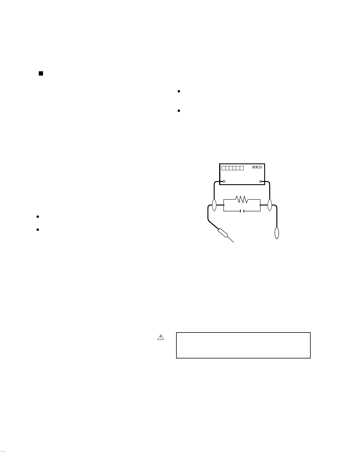
3. To be sure that no shock hazard exists, check for
current leakage in the following manner:
Plug the AC cord directly into a 120 - volt AC outlet,
(Do not use an isolation transformer for this test).
Using two clip leads, connect a 1.5k ohm, 10 watt
resistor paralleled by a 0.15µF capacitor in parallel
between all exposed metal cabinet parts and earth
ground.
Service Manual
Use an AC voltmeter with sensitivity of 5000 ohm per
volt., or higher, sensitivity to measure the AC voltage
drop across the resistor.
All checks must be repeated with the AC plug
connection reversed. (If necessary, a non-polarized
adapter plug must be used only for the purpose of
completing these checks.)
Any reading of 0.4 volts RMS (this corresponds to 0.27
milliamp. AC.) or more is excessive and indicates a
potential shock hazard which must be corrected before
returning the unit to the owner.
DVM
AC SCALE
1.5k ohm
10W
0.15 µF
TEST PROBE
TO EXPOSED
METAL PARTS
CONNECT TO
KNOWN EARTH
GROUND
/////////////////////////////////////////////////////////////////////////////////////////////////////////////////////////////////////////////////
SAFETY NOTICE
Many electrical and mechanical parts in DMD™
Projector have special safety-related characteristics.
These characteristics are often not evident from visual
inspection, nor can protection afforded by them be
necessarily increased by using replacement components
rated for higher voltage, wattage, etc.
Replacement parts which have these special safety
characteristics are identified in this manual; electrical
components having such features are identified by “ ”
and shaded areas in the Replacement Parts Lists and
Schematic Diagrams. For continued protection,
/////////////////////////////////////////////////////////////////////////////////////////////////////////////////////////////////////////////////
replacement parts must be identical to those used in
the original circuit. The use of a substitute replacement
parts which do not have the same safety characteristics
as the factory recommended replacement parts shown
in this service manual, may create shock, fire or other
hazards.
WARNING: The bimetallic component has the primary
conductive side exposed. Be very careful in
handling this component when the power is on.
i
Page 3
XV-Z3100U/XV-Z3100/XV-Z3300/DT-510
PRECAUTIONS A PRENDRE LORS DE LA REPARATION
Ne peut effectuer la réparation qu' un technicien spécialisé qui s'est parfaitement
accoutumé à toute vérification de sécurité et aux conseils suivants.
AVERTISSEMENT
1. N'entreprendre aucune modification de tout circuit.
C'est dangereux.
2. Débrancher le récepteur avant toute réparation.
VERIFICATIONS CONTRE L'INCEN-DIE ET
LE CHOC ELECTRIQUE
Avant de rendre le récepteur à l'utilisateur, effectuer
les vérifications suivantes.
1. Inspecter tous les faisceaux de câbles pour s'assurer
que les fils ne soient pas pincés ou qu'un outil ne soit
pas placé entre le châssis et les autres pièces
métalliques du récepteur.
2. Inspecter tous les dispositifs de protection comme les
boutons de commande non-métalliques, les isolants, le
dos du coffret, les couvercles ou blindages de réglage
et de compartiment, les réseaux de résistance-capacité,
les isolateurs mécaniques, etc.
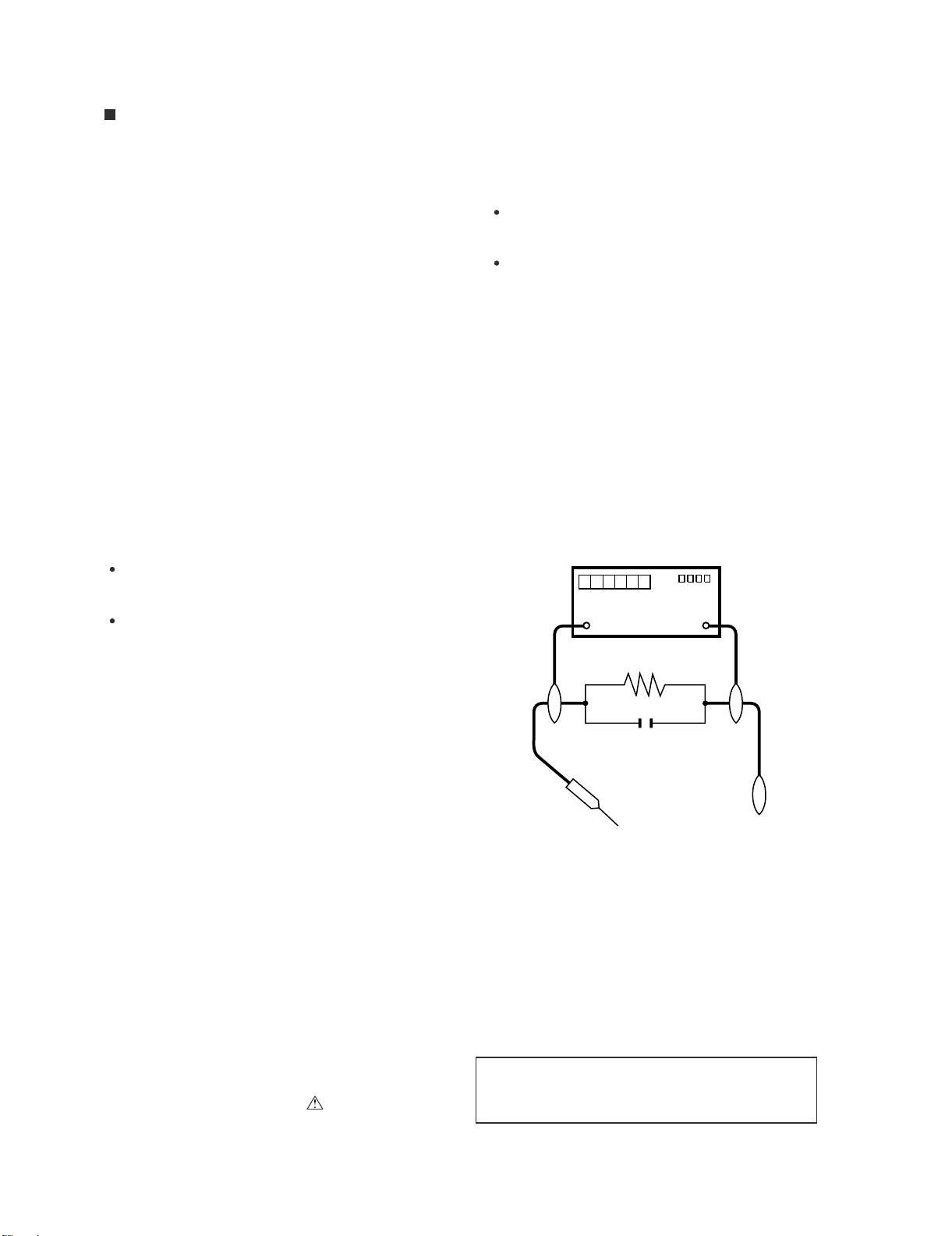
3. S'assurer qu'il n'y ait pas de danger d'électrocution en
vérifiant la fuite de courant, de la facon suivante:
Brancher le cordon d'alimentation directem-ent à une
prise de courant de 120 - V. (Ne pas utiliser de
transformateur d'isolation pour cet essai).
A l'aide de deux fils à pinces, brancher une résistance
de 1.5 kΩ 10 watts en parallèle avec un condensateur
de 0.15µF en série avec toutes les pièces métalliques
exposées du coffret et une terre connue comme une
conduite électrique ou une prise de terre branchée à la
terre.
Utiliser un voltmètre CA d'une sensibilité d'au moins
5000Ω/V pour mesurer la chute de tension en travers
de la résistance.
Toucher avec la sonde d'essai les pièces métalliques
exposées qui présentent une voie de retour au châssis
(antenne, coffret métallique, tête des vis, arbres de
commande et des boutons, écusson, etc.) et mesurer la
chute de tension CA en-travers de la résistance. Toutes
les vérifications doivent être refaites après avoir inversé
la fiche du cordon d'alimentation. (Si nécessaire, une
prise d'adpatation non polarisée peut être utilisée dans
le but de terminer ces vérifications.)
La tension de pointe mesurèe ne doit pas dépasser 0.4V
(correspondante au courant CA de pointe de 0.27mA).
Dans le cas contraire, ilyaunepossibilité de choc
électrique qui doit être supprimée avant de rendre le
récepteur au client.
DVM
ECHELLE CA
1.5k ohm
10W
0.15
µ
SONDE D'ESSAI
AUX PIECES
METALLIQUES
EXPOSEES
F
BRANCHER A UNE
TERRE CONNUE
/////////////////////////////////////////////////////////////////////////////////////////////////////////////////////////////////////////////////////
AVIS POUR LA SECURITE
De nombreuses pièces, électriques et mécaniques, dans
les projecteur à DMD™ présentent des caractéristiques
spéciales relatives à la sécurité, qui ne sont souvent pas
évidentes à vue.
Le degré de protection ne peut pas être nécessairement
augmentée en utilisant des pièces de remplacement
étalonnées pour haute tension, puissance, etc.
Les pièces de remplacement qui présentent ces
caractéristiques sont identifiées dans ce manuel;
les pièces électriques qui présentent ces particularités
sont identifiées par la marque “ ” et hachurées dans la
/////////////////////////////////////////////////////////////////////////////////////////////////////////////////////////////////////////////////////
liste des pièces de remplacement et les diagrammes
schématiques. Pour assurer la protection, ces pièces
doivent être identiques à celles utilisées dans le circuit
d’origine. L’utilisation de pièces qui n’ont pas les mêmes
caractéristiques que les pièces recommandées par l’usine,
indiquées dans ce manuel, peut provoquer des
électrocutions, incendies ou autres accidents.
AVERTISSEMENT: La composante bimétallique dispose du
conducteur primaire dénudé. Faire attention
lors de la manipulation de cette
composante sous tension.
ii
Page 4
XV-Z3100U/XV-Z3100/XV-Z3300/DT-510
NOTE TO SERVICE
PERSONNEL
//////////////////////////////////////////////////////////////
UV-RADIATION PRECAUTION
//////////////////////////////////////////////////////////////
The light source, lamp, in the project or emits small
amounts of UV-Radiation.
AVOID DIRECT EYE AND SKIN EXPOSURE.
To ensure safety please adhere to the following:
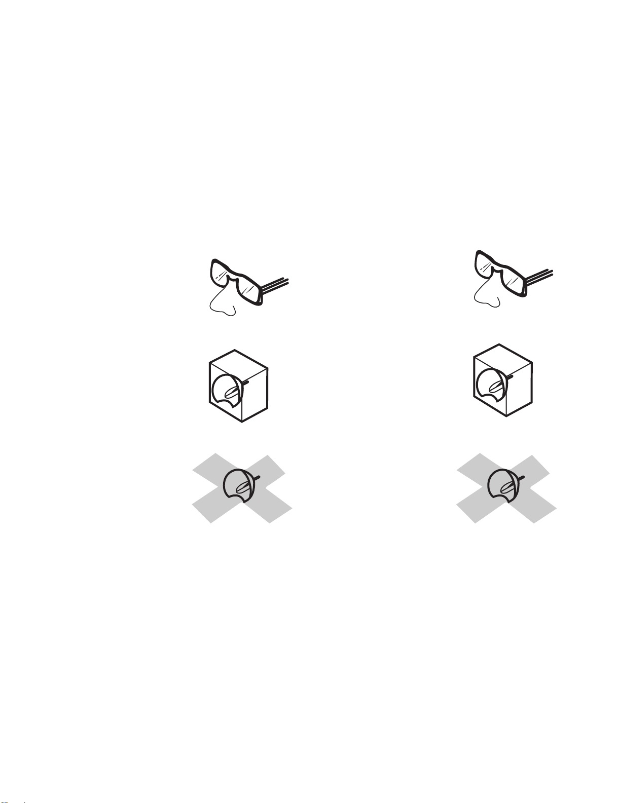
1. Be sure to wear sun-glasses when servicing the
projector with the lamp
turned “on” and the top
enclosure removed.
2. Do not operate the lamp outside of the lamp housing.
NOTE POUR LE PERSONNEL
D’ENTRETIEN
//////////////////////////////////////////////////////////////
PRECAUTION POUR LES RADIATIONS UV
//////////////////////////////////////////////////////////////
La source de lumière, la lampe, dans le projecteur
émet de petites quantités de radiation UV.
EVITEZ TOUTE EXPOSITION DIRECTE DES
YEUX ET DE LA PEAU.
Pour votre sécurité, nous vous prions de respecter
les points suivants:
1. Toujours porter des lunettes de soleil lors d’un entretien
du projecteur
avec la lampe allumée
et le haut du coffret retiré.
2. Ne pas faire fonctionner la lampe à l’extérieur du boîtier
de lampe.
3. Do not operate for more than 2 hours with the enclosure
removed.
UV-Radiation and Medium Pressure
Lamp Precautions
1. Be sure to disconnect the AC plug when replacing the
lamp.
2. Allow one hour for the unit to cool down before
servicing.
3. Replace only with same type lamp. Type AN-XR10L2
rated 220 W DC.
4. The lamp emits small amounts of UV-Radiation, avoid
direct-eye contact.
5. The medium pressure lamp involves a risk of explosion.
Be sure to follow installation instructions described
below and handle the lamp with care.
3. Ne pas faire fonctionner plus de 2 heures avec le coffret
retiré.
Précautions pour les radiations UV
et la lampe moyenne pression
1. Toujours débrancher la fiche AC lors du remplacement
de la lampe.
2. Laisser l’unité refroidir pendant une heure avant de
procéder à l’entretien.
3. Ne remplacer qu’avec une lampe du même type. Type
AN-XR10L2, caractéristique 220 W-DC.
4. La lampe émet de petites quantités de radiation UVéviter tout contact direct avec les yeux.
5. La lampe moyenne pression implique un risque
d’explosion. Toujours suivre les instructions
d’installation décrites ci-dessous et manipuler la lampe
avec soin.
iii
Page 5

XV-Z3100U/XV-Z3100/XV-Z3300/DT-510
////////////////////////////////////////////////////////////////
UV-RADIATION PRECAUTION (Continued)
////////////////////////////////////////////////////////////////
Lamp Replacement
Note:
Since the lamp reaches a very high temperature during
units operation replacement of the lamp should be
done at least one hour after the power has been turned
off. (to allow the lamp to cool off.)
Installing the new lamp, make sure not to touch the
lamp (bulb) replace the lamp by holding its reflector
2
.
[Use original replacement only.]
Lamp
1
Reflector
2
DANGER ! –– Never turn the power on without the
lamp to avoid electric-shock or damage of the devices
since the stabilizer generates high voltages at its start.
////////////////////////////////////////////////////////////////
PRECAUTION POUR LES RADIATIONS UV (Suite)
////////////////////////////////////////////////////////////////
Remplacement de la lampe
Remarque:
Comme la lampe devient très chaude pendant le
fonctionnement de l’unité, son remplacement ne doit
être effectué au moins une heure après avoir coupé
l’alimentation (pour permettre à la lampe de refroidir).
En installant la nouvelle lampe, s’assurer de ne pas
toucher la lampe (ampoule). Remplacer la lampe en
tenant son réflecteur .
[N’utiliser qu’un remplacement d’origine.]
DANGER ! –– Ne jamais mettre sous tension sans la
lampe pour éviter un choc électrique ou des
dommages des appareils car le stabilisateur génère
de hautes tensions à sa mise en route.
2
1
Lampe
2
Reflecteur
Since small amounts of UV-radiation are emitted
from an opening between the exhaust fans, it is recommended to place the cap of the optional lens on
the opening during servicing to avoid eye and skin
exposure.
To illuminate the lamp in the unit with Top Body
removed, attach the above Service Top Body
(DBDYTA132WJZZ). If not, problems may be caused
by UV light emitted from the lamp.
Top Body
Part code:DBDYTA132WJZZ
Comme de petites quantités de radiation UV sont
émises par une ouverture entre les ventilateurs aspirants, il est recommandé de placer le capuchon de
l’optique optionnelle sur l’ouverture pendant l’entretien
pour éviter une exposition des yeux et la peau.
Pour allumer la lampe de l'appareil après avoir retiré
l'enveloppe supérieure, fixer l'enveloppe supérieure
de service ci-dessus (DBDYTA132WJZZ). Dans le cas
contraire, il peut se produire un problème dû à
l'émission de rayons UV.
Enveloppe supérieur
Code de pièce:DBDYTA132WJZZ
iv
Page 6
XV-Z3100U/XV-Z3100/XV-Z3300/DT-510
WARNING: High brightness light source, do not stare into the beam of light, or view directly. Be especially
careful that
children do not stare directly in to the beam of light.
WARNING: TO REDUCE THE RISK OF FIRE OR ELECTRIC SHOCK, DO NOT EXPOSE
THIS UNIT TO
MOISTURE OR WET LOCATIONS.
CAUTION
RISK OF ELECTRIC SHOCK.
DO NOT REMOVE SCREWS
EXCEPT SPECIFIED USER
SERVICE SCREW.
CAUTION: TO REDUCE THE RISK OF ELECTRIC SHOCK,
DO NOT REMOVE CABINET.
NO USER-SERVICEABLE PARTS EXCEPT LAMP UNIT.
REFER SERVICING TO QUALIFIED SERVICE
PERSONNEL.
The lighting flash with arrowhead within a
triangle is intended to tell the user that
parts inside the product are risk of electric
shock to persons.
The exclamation point within a triangle is
intended to tell the user that important
operating and servicing instructions are in
the manual with the projector.
CAUTION
(POWER Unit)
6.3A 250V
For continued
protection against a
risk of fire, replace
only with same type
6.3A, AC250V fuse.
(F701)
//////////////////////////////////////////////////////////////////////////////////////////////////////////////////////////////////
AVERTISSEMENT: Source lumineuse de grande intensité. Ne pas fixer le faisceau lumineux ou le regarder
directement. Ve
iller particulièrement à éviter que les enfants ne fixent directement le
faisceau lumineux.
AVERTISSEMENT: AFIN D’EV
ITER TOUT RISQUE D’INCENDIE OU D’ELECTROCUTION, NE PAS PLACER
CET APPAREIL DANS UN ENDROIT HUMIDE OU MOUILLE.
ATTENTION
RISQUE
D’ÉLECTROCUTION. NE
PASR ETIRER LES VIS Á
L’EXCEPTION DE LA VIS DE
REPARATION UTILISATEUR
SPECIFIEES
L’éclair terminé d’une flèche à l’intérieur
d’un triangle indique à l’utilisateur que les
pi‘eces se trouvant dans l’appareil sont
susceptibles de provoquer une décharge
électrique.
Le point d’exclamation à l’intérieur d’un
ATTENTION: POUR EVITER TOUT RISQUE
D’ELECTROCUTION, NE PAS RETIRER LE CAPOT.
AUCUNE DES PIECES INTERIEURES N’EST REPARABLE
PAR L’UTILISATEUR, A L’EXCEPTION DE L’UNITE DE
LAMPE. POUR TOUTE REPARATION, S’ADRESSER A UN
TECHNICIEN D’ENTRETIEN QUALIFIE.
triangle indique à l’utilisateur que les
instructions de fonctionnement et
d’entretien sont détaillées dans les
documents fournis avec le projecteur.
PRECAUTION
(Unité de PUTSSANCE)
6.3A 250V
Pour une protection
continue contre un
risques d’incendie, ne
remplacer qu’avec un
fusible 6.3A,AC250V
du même type.
(F701)
v
Page 7
XV-Z3100U/XV-Z3100/XV-Z3300/DT-510
Precautions for using lead-free solder
Employing lead-free solder
• "PWBs" of this model employs lead-free solder. The LF symbol indicates lead-free solder, and is attached on the PWBs and service manuals. The
alphabetical character following LF shows the type of lead-free solder.
Example:
L Fa
Indicates lead-free solder of tin, silver and copper.
Using lead-free wire solder
• When fixing the PWB soldered with the lead-free solder, apply lead-free wire solder. Repairing with conventional lead wire solder may cause damage or accident due to cracks.
As the melting point of lead-free solder (Sn-Ag-Cu) is higher than the lead wire solder by 40 °C, we recommend you to use a dedicated soldering
bit, if you are not familiar with how to obtain lead-free wire solder or soldering bit, contact our service station or service branch in your area.
Soldering
• As the melting point of lead-free solder (Sn-Ag-Cu) is about 220 °C which is higher than the conventional lead solder by 40 °C, and as it has poor
solder wettability, you may be apt to keep the soldering bit in contact with the PWB for extended period of time. However, Since the land may be
peeled off or the maximum heat-resistance temperature of parts may be exceeded, remove the bit from the PWB as soon as you confirm the
steady soldering condition.
Lead-free solder contains more tin, and the end of the soldering bit may be easily corroded. Make sure to turn on and off the power of the bit as
required.
If a different type of solder stays on the tip of the soldering bit, it is alloyed with lead-free solder. Clean the bit after every use of it.
When the tip of the soldering bit is blackened during use, file it with steel wool or fine sandpaper.
• Be careful when replacing parts with polarity indication on the PWB silk.
Lead-free wire solder for servicing
Part No. Description Code
ZHNDAi123250E J φ0.3mm 250g(1roll) BL
ZHNDAi126500E J φ0.6mm 500g(1roll) BK
ZHNDAi12801KE J φ1.0mm 1kg(1roll) BM
vi
Page 8

XV-Z3100U/XV-Z3100/XV-Z3300/DT-510
XV-Z3100U
CHAPTER 1. OPERATION MANUAL
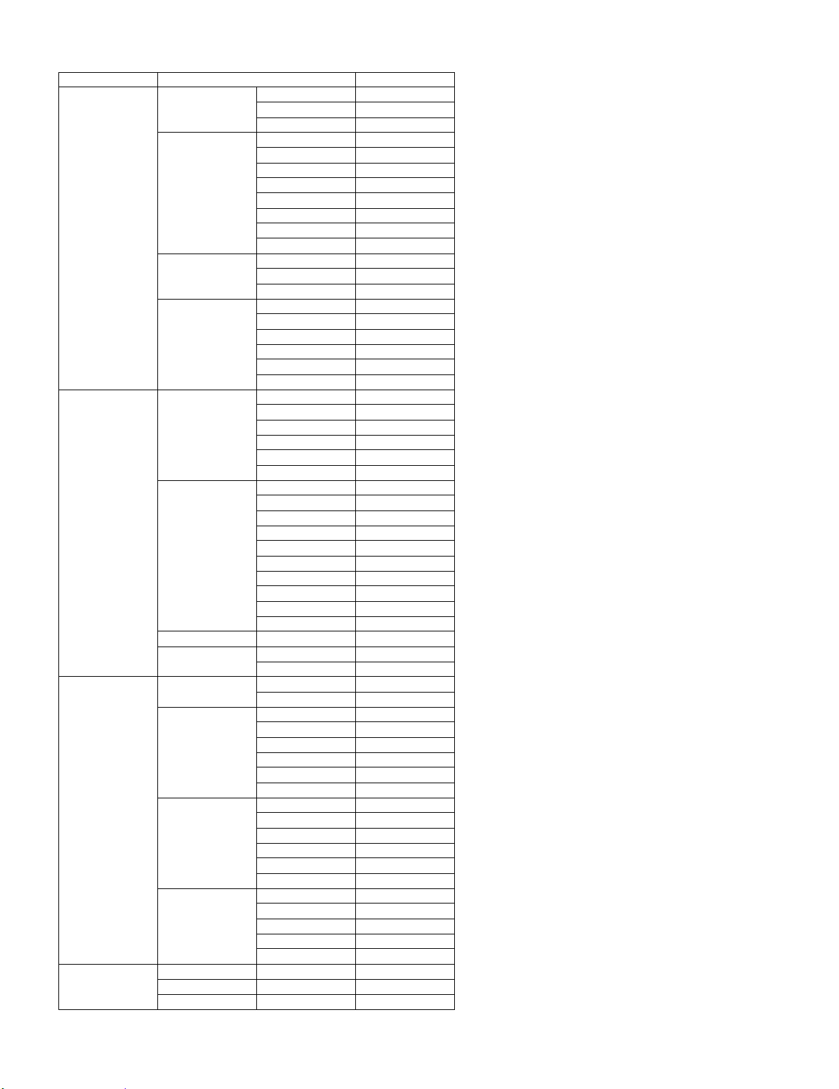
[1] Specifications
Service Manual
Product type
Model
Video system
Display method
Lens
Projection lamp
Component input signal
(INPUT1/2)
S-video input signal
(INPUT 3)
Video input signal
(INPUT 4)
Computer RGB/
Component input signal
(INPUT 5)
HDMI input signal
(INPUT 6)
Horizontal resolution
Vertical frequency
Horizontal frequency
Pixel clock
RS-232C terminal
TRIGGER terminal
Rated voltage
Input current
Rated frequency
Power consumption
Power consumption (standby)
Heat dissipation
Operating temperature
Storage temperature
Cabinet
I/R carrier frequency
Dimensions (approx.)
Weight (approx.)
Replacement parts
Projector
XV-Z3100U, XV-Z3100, XV-Z3300, DT-510
NTSC3.58/NTSC4.43/PAL/PAL-M/PAL-N/PAL-60/SECAM/DTV480
DTV540P/DTV576
R
DLP chip
Panel size: 0.62"ı
Drive method: Digital Light Processing (DLP
/DTV576P/DTV720P/DTV1035 /DTV1080 /DTV1080 -50
R
)
/DTV480P/
No. of dots:921,600 dots (1280 [H] 720 [V])
1−1.15 x zoom lens, F2.4−2.6, f = 19.0−21.9 mm
220 W DC lamp
RCA connector
Y: 1.0 Vp-p, sync negative, 75 Ω terminated
): 0.7 Vp-p, 75 Ω terminated
P
B(CB
): 0.7 Vp-p, 75 Ω terminated
P
R(CR
4-pin mini DIN connector
Y (luminance signal): 1.0 Vp-p, sync negative, 75 Ω terminated
C (chrominance signal): Burst 0.286 Vp-p, 75 Ω terminated
RCA connector: VIDEO, composite video, 1.0 Vp-p, sync negative, 75 Ω
terminated
15-pin mini D-sub connector
RGB separate/sync on green type analog input: 0−0.7 Vp-p, positive, 75Ωterminated
HORIZONTAL SYNC. SIGNAL: TTL level (positive/negative)
VERTICAL SYNC. SIGNAL: Same as above
HDMI terminal (video signal only)
720 TV lines (DTV720P)
45−85 Hz
15−70 kHz
12−85 MHz
9-pin mini DIN connector (XV-Z3100U, XV-Z3100, XV-Z3300)
Power jack: DC 12V output (XV-Z3100U, XV-Z3100, XV-Z3300)
AC 100−240 V
3.1 A
50/60 Hz
303 W (Lamp Setting "Bright")/
234 W (Lamp Setting "Eco + Quiet")
with AC 100 V
293 W (Lamp Setting "Bright")/
228 W (Lamp Setting "Eco + Quiet")
4W(AC100V)− 5 W (AC 240 V)*
with AC 240 V
1
1,140 BTU/hour (Lamp Setting "Bright")/
1,100 BTU/hour (Lamp Setting "Eco + Quiet") with AC 100 V
880 BTU/hour (Lamp Setting "Bright")/
860 BTU/hour (Lamp Setting "Eco + Quiet") with AC 240 V
41Fto95F(+5Cto+35C)
− 4Fto140F(− 20 Cto+60 C)
Plastic
38 kHz
13
/32"x4ı19/64"xı111/32" (315 (W) x 109 (H) x 280 (D) mm) (main body only)ı
12
13
12
/32"xı447/64"xı1137/64" (315 (W) x 120 (H) x 294 (D) mm) (including adjust-ı
ment foot and projecting parts)
8.8 lbs. (4.0 kg)
Remote control, Power cord, 21 pin RCA conversion adaptor (except for U.S.A.
and Canada), Video cable (except for U.S.A. and Canada), Operation manual
1
*
When STANDBY Mode is set to "Eco"
As a part of policy of continuous improvement, SHARP reserves the right to make design and
specification changes for product improvement without prior notice. The performance specification figures indicated are nominal values of production units. There may be some deviations from
these values in individual units.
1 – 1
Page 9
[2] Parts Name and Basic Operation
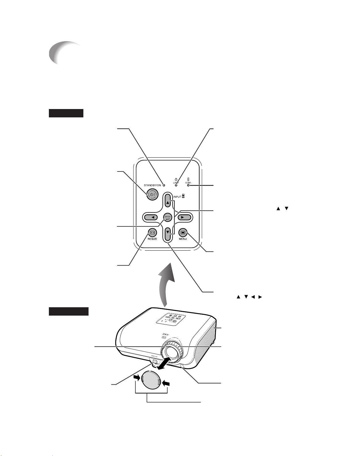
Part Names and Functions
Projector
Top View
XV-Z3100U/XV-Z3100/XV-Z3300/DT-510
Power
indicator
STANDBY/ON
button
For turning the
power on and
putting the
projector into
standby mode.
ENTER button
For setting
items selected
or adjusted on
the menu.
RESIZE button
For switching
the screen
size.
Front View
Lamp indicator
Temperature warning
indicator
INPUT buttons ( / )
For switching input mode
1, 2, 3, 4, 5 or 6.
MENU button
For displaying
adjustment and
setting screens.
Adjustment buttons
(///)
For selecting menu items.
Focus ring
For adjusting
the focus.
HEIGHT
ADJUST
lever
Intake vent
Zoom ring
For enlarging/
reducing the picture.
Remote control
sensor (front)
Push both sides of the lens cap
to attach or remove.
1 – 2
Page 10
XV-Z3100U/XV-Z3100/XV-Z3300/DT-510
Rear View
Exhaust vent
Intake vent
AC socket
Connect the
supplied Power cord.
Rear adjustment
foot
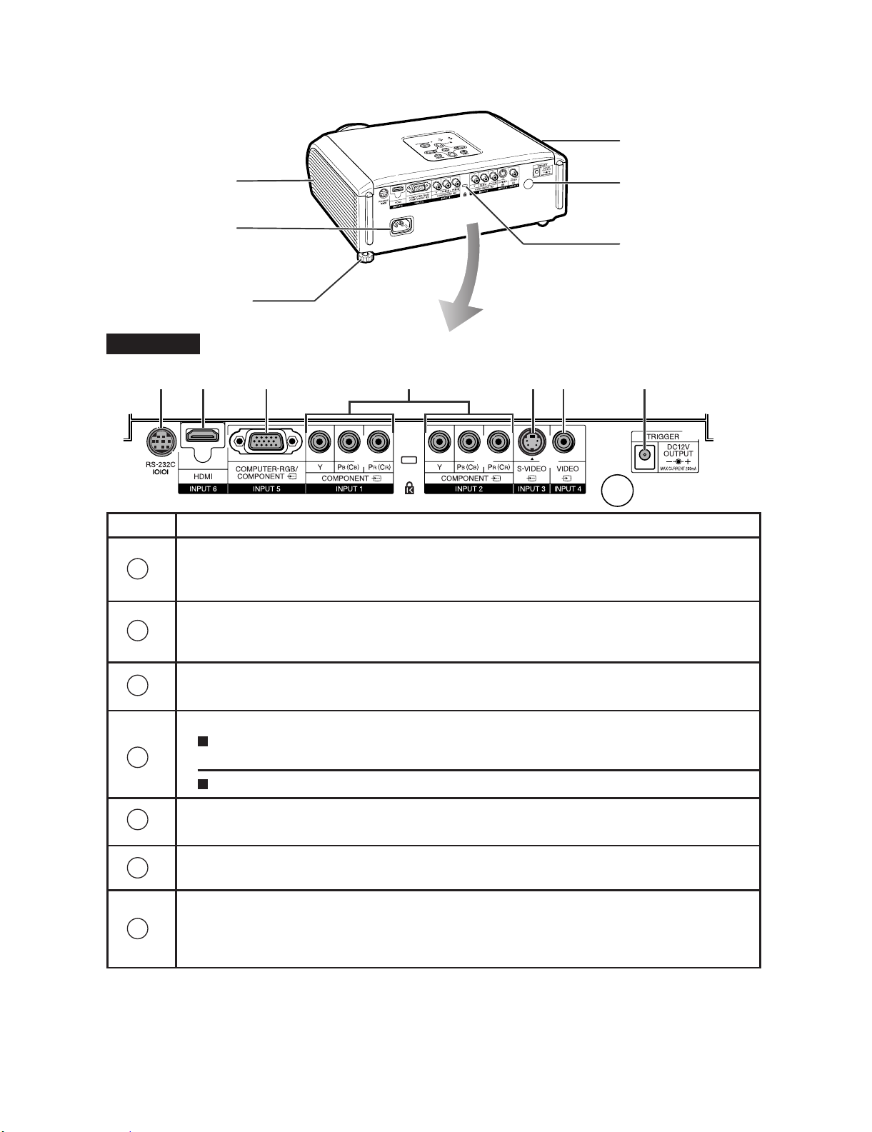
Terminals
65 4 1 23 7
Terminal Description
INPUT 1, 2 terminal
1
Connecting video equipment with component output terminal (DVD
player, DTV decoder, DVD recorder with hard disc, etc.).
Remote control
sensor (rear)
Kensington
Security Standard
connector
INPUT 3 terminal
2
3
4
5
6
7
Connecting video equipment with S-video output terminal (VCR, DVD
player, etc.).
INPUT 4 terminal
Connecting video equipment without S-video output terminal.
INPUT 5 terminal
Connecting video equipment with component output terminal
(DVD player, DTV decoder, DVD recorder with hard disc, etc.).
ı
Connecting the computer.
INPUT 6 terminal
Connecting video equipment with HDMI output terminal.
RS-232C terminal
Connecting the computer to control the projector.
TRIGGER terminal (only XV-Z3100U, XV-Z3100, XV-Z3300)
When the projector is turned on, a control signal (DC 12V) outputs from this
terminal. If an electric screen or other compatible device is connected, it
can be turned on when the projector is turned on.
1 – 3
Page 11
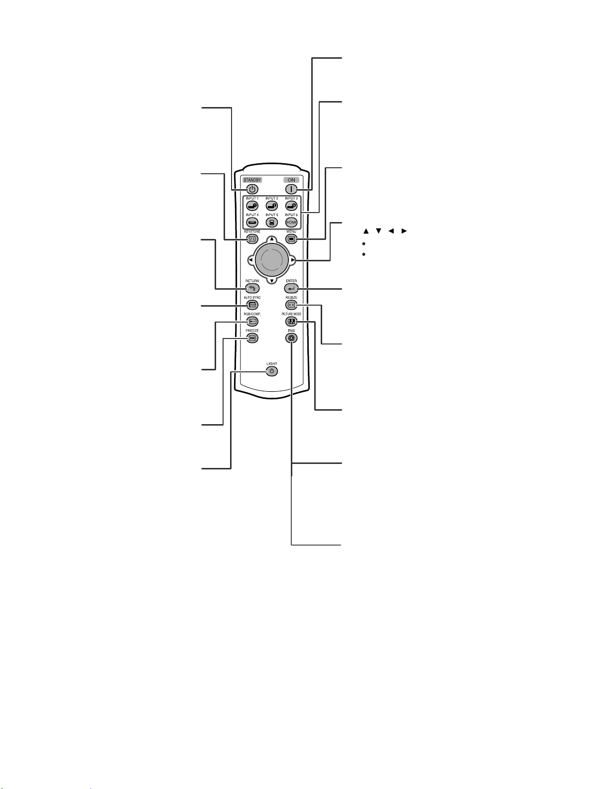
XV-Z3100U/XV-Z3100/XV-Z3300/DT-510
ON button
For turning the power on.
STANDBY button
For putting the
projector into the
standby mode.
KEYSTONE button
For entering the
Keystone Correction
mode.
RETURN button
For returning to the
previous menu screen
during menu operations.
AUTO SYNC button
For automatically
adjusting images
when connected to a
computer.
RGB/COMP. button
For switching to the
respective input signal type.
INPUT1,2,3,4,5and6
buttons
For switching to the
respective input modes.
MENU button
For displaying adjustment
and setting screens.
Adjustment buttons
(///)
For selecting menu items.
For adjusting the Keystone
Correction when in the
Keystone Correction mode.
ENTER button
For setting items selected
or adjusted on the menu.
RESIZE button
For switching the picture
size (STRETCH, SIDE
BAR, etc.).
FREEZE button
For freezing images.
Backlight button
For lighting all buttons on the
remote control.
PICTURE MODE button
For selecting the appropriate
picture.
IRIS button (only XV-Z3100U, XV-Z3100,
XV-Z3300)
For switching "HIGH
BRIGHTNESS MODE",
"MEDIUM MODE" and
"HIGH CONTRAST MODE".
IRIS button (DT-510)
For switching "HIGH
BRIGHTNESS MODE", and
"HIGH CONTRAST MODE".
1 – 4
Page 12
XV-Z3100U/XV-Z3100/XV-Z3300/DT-510
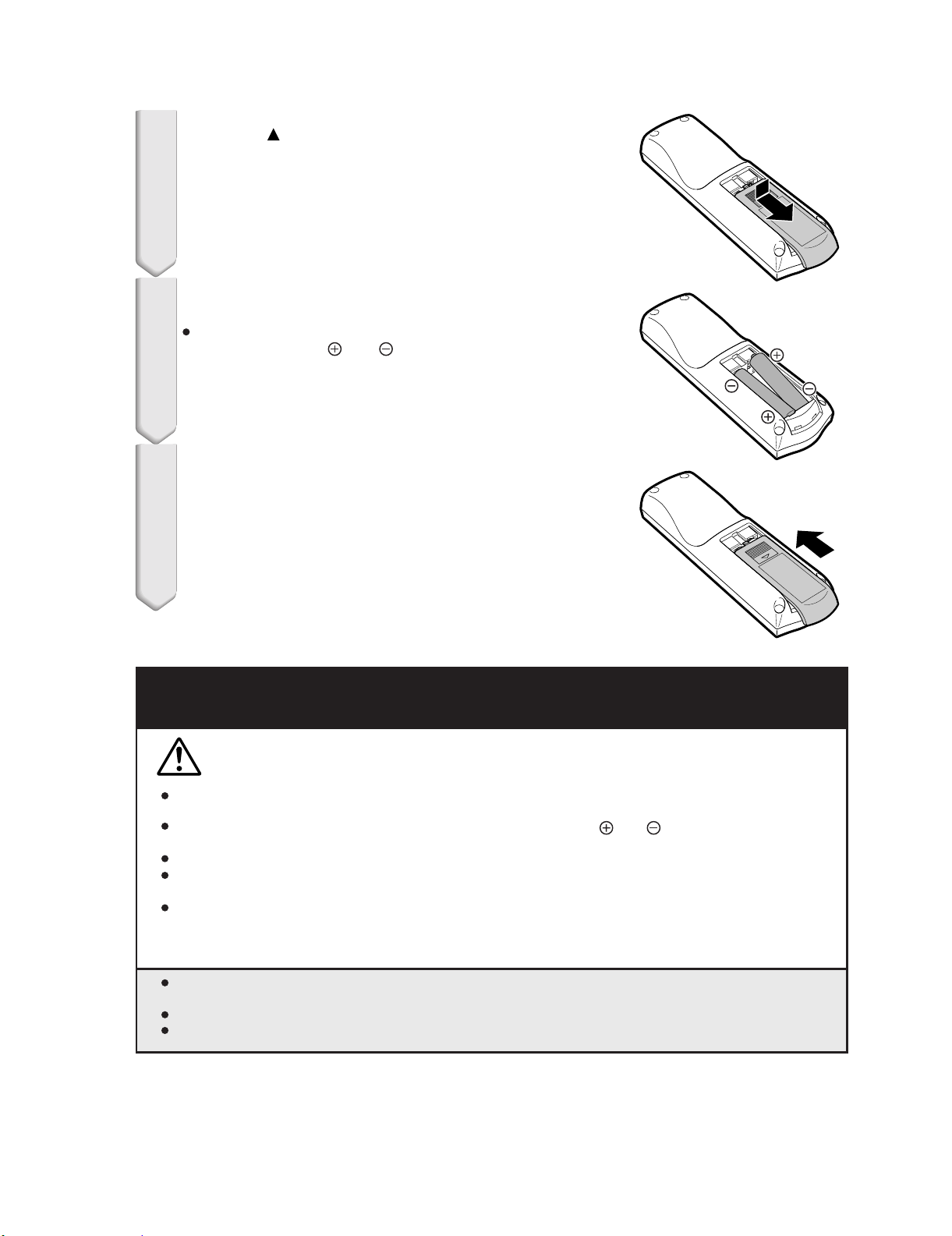
Inserting the Batteries
Press the mark on the cover and slide it
1
in the direction of the arrow.
Insert the batteries.
2
Insert the batteries making sure the polarities
correctly match the and marks inside the
battery compartment.
Attach the cover and slide it until it clicks
3
into place.
Incorrect use of the batteries may cause them to leak or explode. Please
follow the precautions below.
Caution
Danger of explosion if battery is incorrectly replaced.
Replace only with the same or equivalent type.
Insert the batteries making sure the polarities correctly match the and marks inside the battery
compartment.
Batteries of different types have different properties, therefore do not mix batteries of different types.
Do not mix new and old batteries.
This may shorten the life of new batteries or may cause old batteries to leak.
Remove the batteries from the remote control once they have run out, as leaving them in can cause them
to leak.
Battery fluid from leaked batteries is harmful to skin, therefore ensure you wipe them first and then remove
them using a cloth.
The batteries included with this projector may run down in a short period, depending on how they are kept.
Be sure to replace them as soon as possible with new batteries.
Remove the batteries from the remote control if you will not be using the remote control for a long time.
Comply with the rules (ordinance) of each local government when disposing of worn-out batteries.
1 – 5
Page 13
XV-Z3100U/XV-Z3100/XV-Z3300/DT-510
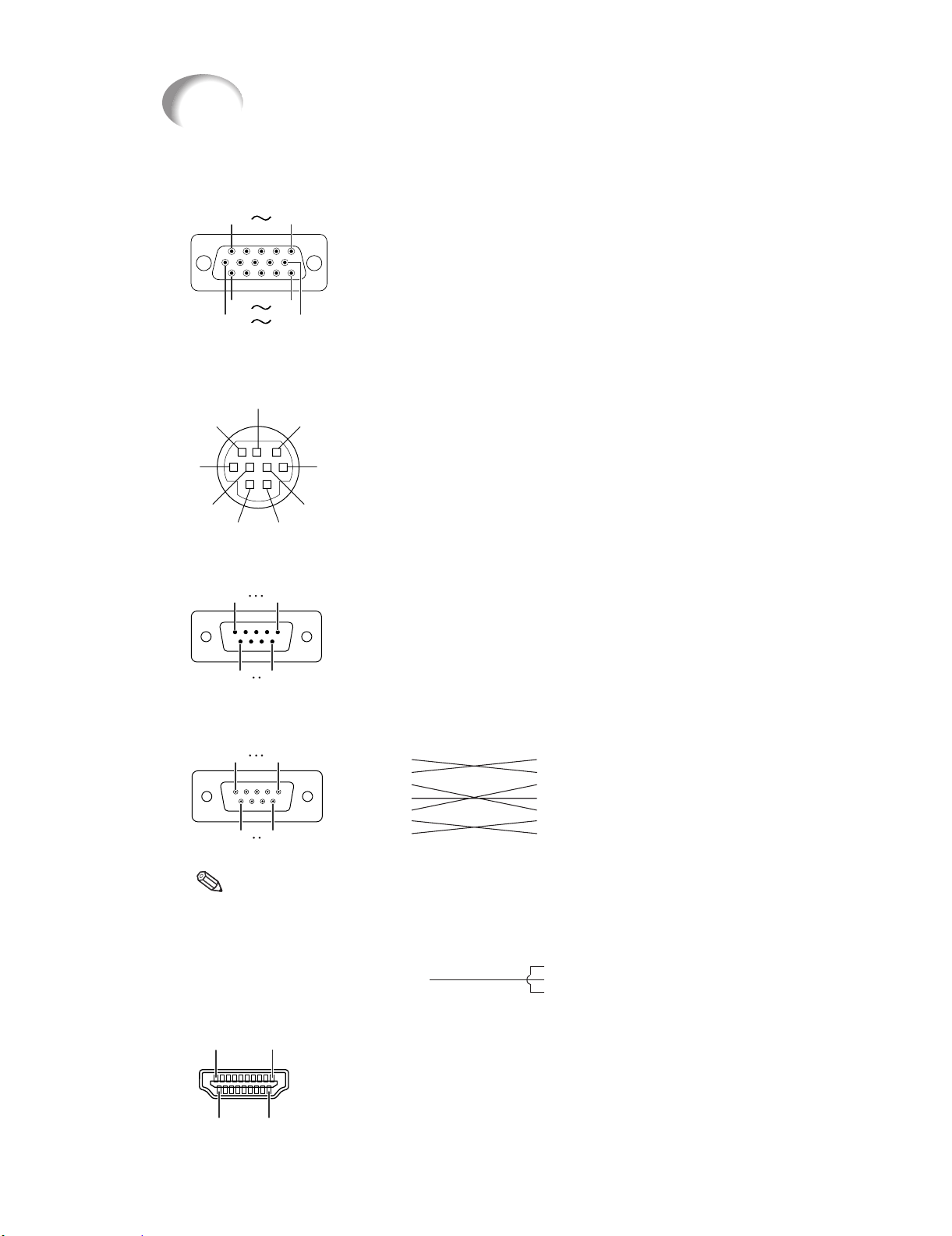
Connecting Pin Assignments
COMPUTER-RGB/COMPONENT INPUT5 Terminal: 15-pin Mini D-sub female connector
COMPUTER-RGB Input
1. Video input (red)
2. Video input (green/sync on green)
11
1
6
RS-232C Terminal: 9-pin Mini DIN female connector
15
5
10
8
9
6
5
21
RS-232C Terminal: 9-pin D-sub male connector of the DIN-D-sub RS-232C adaptor
(optional accessory: AN-A1RS)
15
69
RS-232C Cable recommended connection: 9-pin D-sub female connector
51
96
3. Video input (blue)
4. Not connected
5. Not connected
6. Earth (red)
7. Earth (green/sync on green)
8. Earth (blue)
9. Not connected
10. GND
11. Not connected
12. Bi-directional data
13. Horizontal sync signal: TTL level
14. Vertical sync signal: TTL level
15. Data clock
Pin No.
7
3
4
Signal Name
1.
2.
RD
3.
SD
4.
5.
SG
6.
7.
RS
8.
CS
9.
Signal NamePin No.
1.
RD
2.
SD
3.
4.
SG
5.
6.
RS
7.
CS
8.
9.
SignalPin No.
1.
CD
RD
2.
SD
3.
4.
ER
SG
5.
DR
6.
RS
7.
CS
8.
CI
9.
Receive Data
Send Data
Signal Ground
Request to Send
Clear to Send
Receive Data
Send Data
Signal Ground
Request to Send
Clear to Send
I/O Reference
Input
Output
I/O Reference
Input
Output
1.
2.
3.
4.
5.
6.
7.
8.
9.
Component Input
1. PR (CR)
2. Y
B (CB)
3. P
4. Not connected
5. Not connected
6. Earth (P
7. Earth (Y)
8. Earth (P
9. Not connected
10. Not connected
11. Not connected
12. Not connected
13. Not connected
14. Not connected
15. Not connected
Not connected
Connected to internal circuit
Connected to internal circuit
Not connected
Connected to internal circuit
Not connected
Connected to CS in internal circuit
Connected to RS in internal circuit
Not connected
Not connected
Connected to internal circuit
Connected to internal circuit
Not connected
Connected to internal circuit
Not connected
Connected to CS in internal circuit
Connected to RS in internal circuit
Not connected
SignalPin No.
CD
RD
SD
ER
SG
DR
RS
CS
CI
R)
B)
Note
• Depending on the controlling device used, it may be necessary to connect Pin 4 and Pin 6 on the
controlling device (e.g. computer).
Computer
Pin No.
4
5
6
NamePin No.
TMDS Data0 Shield
8.
TMDS Data0-
9.
TMDS Clock+
10.
TMDS Clock Shield
11.
TMDS Clock-
12.
CEC
13.
NamePin No.
Reserved
14.
SCL
15.
SDA
16.
DDC/CEC Ground
17.
+5V Power
18.
Hot Plug Detect
19.
HDMI Terminal
119
218
Projector
Pin No.
NamePin No.
1.
TMDS Data2+
2.
TMDS Data2 Shield
3.
TMDS Data2-
4.
TMDS Data1+
5.
TMDS Data1 Shield
6.
TMDS Data1-
7.
TMDS Data0+
4
5
6
1 – 6
Page 14
XV-Z3100U/XV-Z3100/XV-Z3300/DT-510
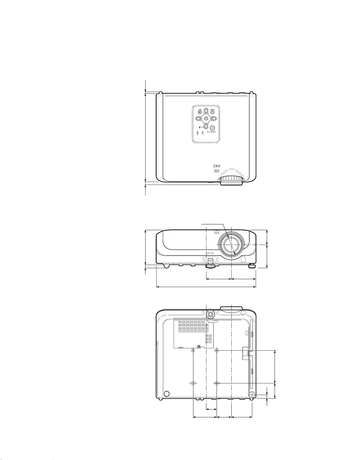
[3] DIMENSIONS
Units: inches (mm)
(5)
64
/
13
(280)
32
/
1
11
(9)
64
/
23
(109)
64
/
19
4
(11)
16
/
7
φ
97/64(69.2)
3
1213/32 (315)
5
/32 (80)
1
3
/16 (77.5)
(47)
64
/
55
1
(73)
8
/
7
2
1 – 7
1
11
261/64
/32 (33.8)
(75)
53
1
(46.2)
(104)
64
/
7
(47.5) 4
8
/
7
1
(11)
16
/
7
19
2
(65.5)
/32
/64
Page 15
[4] Regarding the lamp
Regarding the Lamp
Lamp
ı It is recommended that the lamp (sold separately) be replaced when the remaining lamp life becomes
5% or less, or when you notice a significant deterioration in the picture and color quality. The lamp life
(percentage) can be checked with the on-screen display.
ı Purchase a replacement lamp of type AN-XR10L2 from your place of purchase, nearest Sharp
Authorized Service Center or Dealer.
IMPORTANT NOTE TO U.S. CUSTOMERS:
The lamp included with this projector is backed by a 90-day parts and labor limited
warranty. All service of this projector under warranty, including lamp replacement,
must be obtained through a Sharp Authorized Service Center or Dealer. For the
name of the nearest Sharp Authorized Service Center or Dealer, please call tollfree: 1-888-GO-SHARP (1-888-467-4277).
XV-Z3100U/XV-Z3100/XV-Z3300/DT-510
Hg LAMP CONTAINS MERCURY For State Lamp Disposal
Information
www.lamprecycle.org or 1-800-BE-SHARP
U.S.A. ONLY
Caution Concerning the Lamp
This projector utilizes a pressurized mercury lamp. A loud sound may indicate lamp failure. Lamp
failure can be attributed to numerous sources such as: excessive shock, improper cooling, surface
scratches or deterioration of the lamp due to a lapse of usage time.
The period of time up to failure largely varies depending on the individual lamp and/or the condition
and the frequency of use. It is important to note that failure can often result in the bulb cracking.
ı When the lamp replacement indicator and on-screen display icon are illuminated, it is recommended
that the lamp be replaced with a new one immediately, even if the lamp appears to be operating
normally.
ı Should the lamp break, there is also a possibility that glass particles may spread inside of the
projector. In such a case, it is recommended you contact your nearest Sharp Authorized Service
Center or Dealer to assure safe operation.
ı Should the lamp break, the glass particles may spread inside the lamp cage or gas contained in the
lamp may be vented into the room from the exhaust vent. Because the gas in this lamp includes
mercury, ventilate the room well if the lamp breaks and avoid all exposure to the released gas. In case
of exposure to the gas, consult a doctor as soon as possible.
Replacing the Lamp
Do not remove the lamp unit from the projector right after use. The lamp will be very hot and may
cause burn or injury.
ı Carefully change the lamp by following the instructions described in this section. * If you wish,
you may have the lamp replaced at your nearest Sharp Authorized Service Center or Dealer.
If the new lamp does not light after replacement, take your projector to the nearest Sharp Authorized
*
Service Center or Dealer for repair.
1 – 8
Page 16
XV-Z3100U/XV-Z3100/XV-Z3300/DT-510
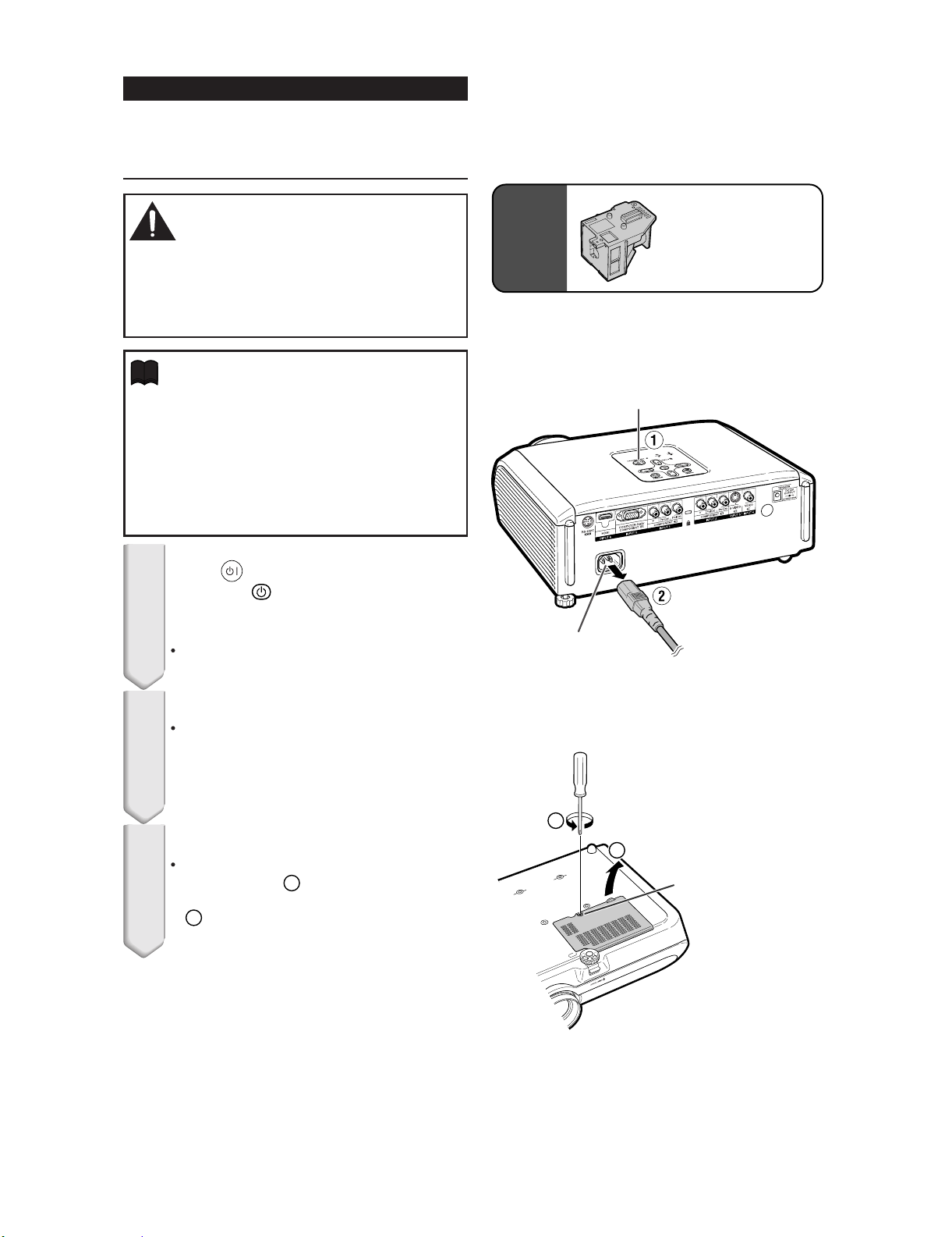
Removing and Installing the
Lamp Unit
Warning!
• The lamp unit becomes very hot while the projector is operating. Do not remove the lamp
unit from the projector right after use. The lamp
and parts around the lamp will be very hot and
may cause burns or injury.
Info
•
Make sure that you remove the lamp unit by
the handle. Do not touch the glass surface of
the lamp unit or the inside of the projector.
•
To avoid injury to yourself and damage to the
lamp, make sure you carefully follow the steps
below.
•
Do not loosen other screws except for the
lamp unit cover and lamp unit.
Press STANDBY/ON on the pro-
1
jector or STANDBY on the remote control to put the projector
into standby mode.
Wait until the cooling fan stops.
Optional
accessory
STANDBY/ON button
AC socket
Lamp unit
AN-XR10L2
Disconnect the power cord.
2
Unplug the power cord from the AC
socket.
Leave the lamp until it has fully cooled
down (about 1 hour).
Remove the lamp unit cover.
3
Turn the projector over. Loosen the user
service screw ( ı ) that secures the lamp
unit cover. Remove the lamp unit cover
(ˇ ).
2
1
1
2
User service scr ew
(for lamp unit cover)
1 – 9
Page 17
XV-Z3100U/XV-Z3100/XV-Z3300/DT-510
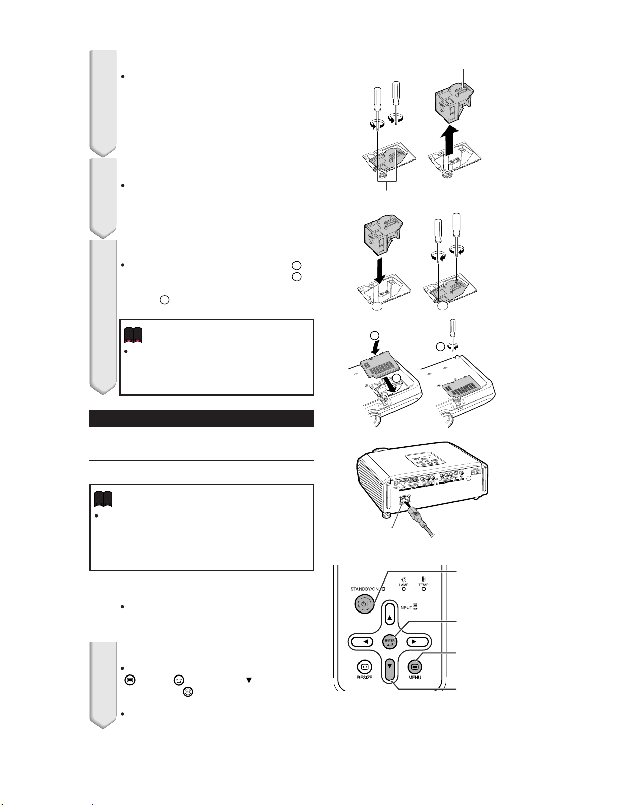
Remove the lamp unit.
4
Loosen the securing screws from the
lamp unit. Hold the lamp unit by the
handle and pull it in the direction of the
arrow. At this time, keep the lamp unit
horizontal and do not tilt it.
Insert the new lamp unit.
5
Press the lamp unit firmly into the lamp
unit compartment. Fasten the securing
screws.
Replace the lamp unit cover.
6
Align the tab on the lamp unit cover ( )
and place it while pressing the tab ( )
to close it. Then tighten the user service
screw ( ) to secure the lamp unit cover.
3
Info
If the lamp unit and lamp unit cover are
not correctly installed, the power will not
turn on, even if the power cord is connected to the projector.
Handle
Securing screws
1
2
2
3
1
Resetting the Lamp Timer
Reset the lamp timer after replacing the lamp.
Info
Make sure to reset the lamp timer only when
replacing the lamp. If you reset the lamp timer
and continue to use the same lamp, this may
cause the lamp to become damaged or explode.
Connect the power cord.
1
Plug the power cord into the AC socket
of the projector.
Reset the lamp timer.
2
While simultaneously holding down
MENU, ENTER and on the projector, press STANDBY/ON on the projector.
"LAMP 0000H" is displayed, indicating
that the lamp timer is reset.
AC socket
STANDBY/ON
button
ENTER button
MENU button
R button
1 – 10
Page 18
XV-Z3100U/XV-Z3100/XV-Z3300/DT-510
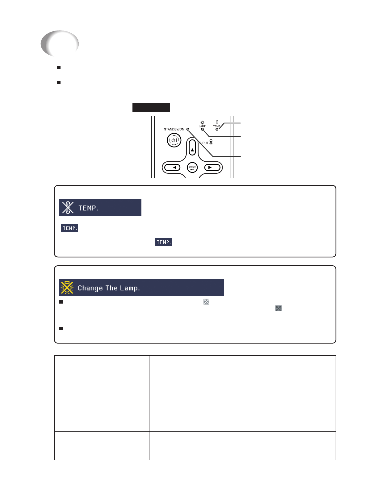
Maintenance Indicators
The warning lights (power indicator, lamp indicator and temperature warning indicator) on the
projector indicate problems inside the projector.
If a problem occurs, either the temperature warning indicator or the lamp indicator will illuminate
red, and the projector will enter standby mode. After the projector has entered standby mode,
follow the procedures given below.
Top View
Temperature warning indicator
Lamp indicator
Power indicator
About the temperature warning indicator
If the temperature inside the projector increases, due to blockage of the air vents, or the setting location,
"
will turn off and the temperature warning indicator will blink, the cooling fan will run, and then the projector will enter standby mode. After "
About the lamp indicator
ı When the remaining lamp life becomes 5% or less, (yellow) and "Change The Lamp" will be
ı If you try to turn on the projector a fourth time without replacing the lamp, the projector will
Indicators on the Projector
Power indicator
Lamp indicator
Temperature warning
indicator
" will illuminate in the lower left corner of the picture. If the temperature keeps on rising, the lamp
" appears, ensure you perform the measures described.
displayed on the screen. When the percentage becomes 0%, it will change to
automatically turn off and then the projector will automatically enter standby mode. At this time, the
lamp indicator will illuminate in red.
not turn on.
Red on
Green on
Red blinks Abnormal
Green blinks
Green on
Green blinks
Red on
Off
Red on
Normal (Standby)
Normal (Power on)
Normal (Cooling)
Normal
The lamp is warming up or shutting down.
The lamp is shut down abnormally or
requires to be changed.
Normal
The internal temperature is abnormally
high.
(red), the lamp will
1 – 11
Page 19
XV-Z3100U/XV-Z3100/XV-Z3300/DT-510
Maintenance indicator
Normal
Tempera-
ture
warning
indicator
Lamp
indicator
Power
indicator
Green on
(Green
when the
lamp is
warming
turning
Green on/
Red on
(Cooling)
Off
blinks
up or
off.)
Green
blinks
Abnormal
Red on
(Standby)
Red on
Red on
(Standby)
Red
blinks
Problem
The internal
temperature is
abnormally
high.
The lamp does
not illuminate.
Time to change
the lamp.
The lamp does
not illuminate.
The power
indicator blinks
in red when the
projector is on.
Cause
Blocked air intake
Cooling fan
breakdown
Internal circuit
failure
Clogged air intake
The lamp is shut
down abnormally.
Remaining lamp life
becomes 5% or
less.
Burnt-out lamp
Lamp circuit failure
The dust filter
holder or lamp unit
cover is open.
Possible Solution
Relocate the projector to
an area with proper
ventilation.
Take the projector to your
nearest Sharp Authorized
Projector Dealer or Service
Center for repair.
Disconnect the power cord
from the AC outlet, and
then connect it again.
Carefully replace the lamp.
Take the projector to your
nearest Sharp Authorized
Projector Dealer or Service
Center for repair.
Please exercise care when
replacing the lamp.
Securely install the cover.
If the power indicator blinks
inredevenwhenthedust
filter holders and lamp unit
cover are securely
installed, contact your
nearest Sharp Authorized
Projector Dealer or Service
Center for advice.
Info
If the temperature warning indicator illuminates, and the projector enters standby mode, follow the
possible solutions above and then wait until the projector has cooled down completely before plugging in the power cord and turning the power back on. (At least 10 minutes.)
If the power is turned off for a brief moment due to power outage or some other cause while using
the projector, and the power supply recovers immediately after that, the lamp indicator will illuminate in red and the lamp may not be lit. In this case, unplug the power cord from the AC outlet,
replace the power cord in the AC outlet and then turn the power on again.
The cooling fan keeps the internal temperature of the projector constant and this function is controlled automatically. The sound of the cooling fan may change during operation because the fan
speed may change and this is not a malfunction.
Do not unplug the power cord after the projector has entered standby mode and while the cooling
fan is running. The cooling fan runs for about 90 seconds.
1 – 12
Page 20
XV-Z3100U/XV-Z3100/XV-Z3300/DT-510
XV-Z3100U
CHAPTER 2. REMOVING OF MAJOR PARTS
Service Manual
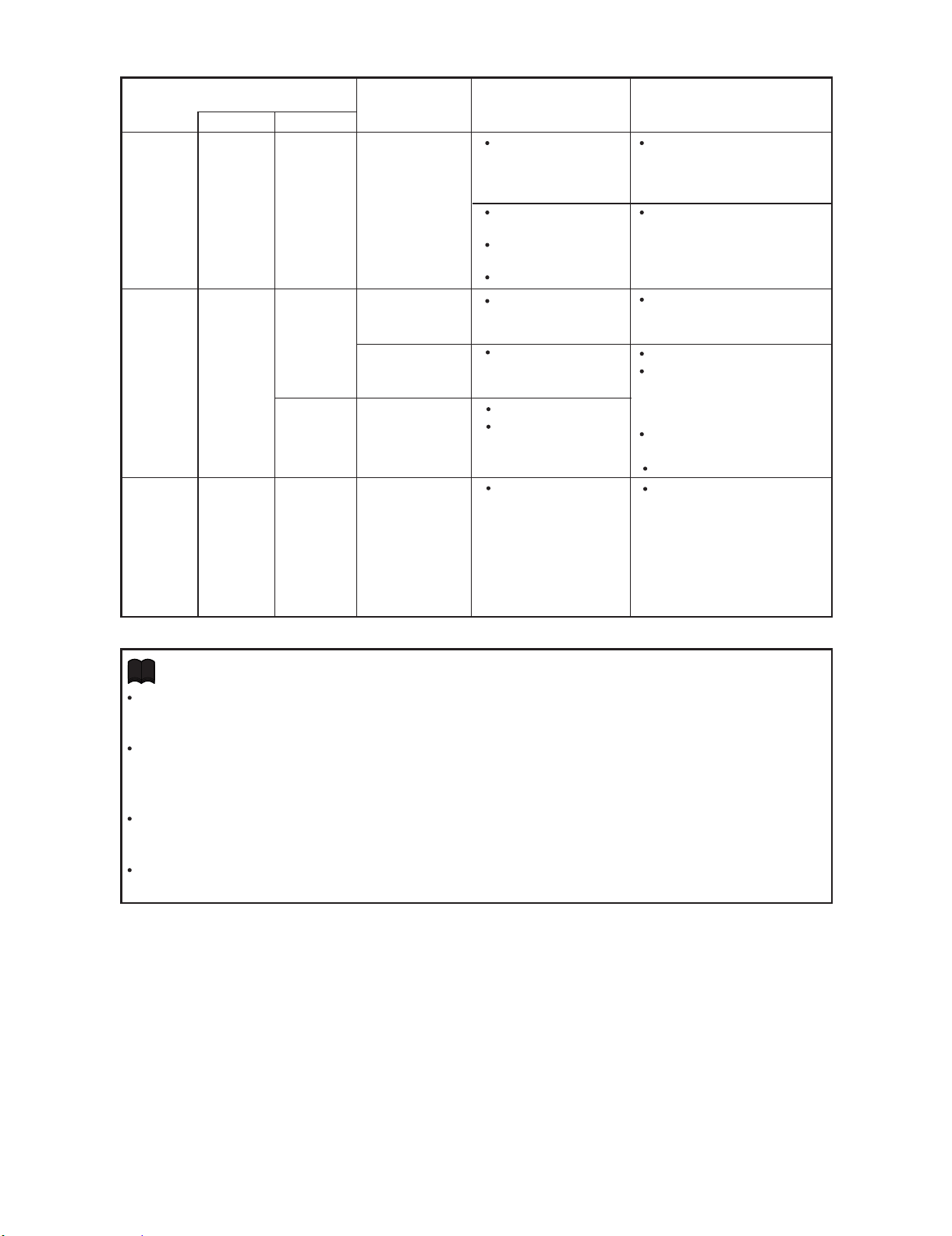
[1] Removing the lamp door and the lamp unit
1. Loosen the lamp door fixing screw. Lift off the lamp door.
2. Remove 2 lamp unit fixing screws to detach the lamp unit.
1
Lamp Door
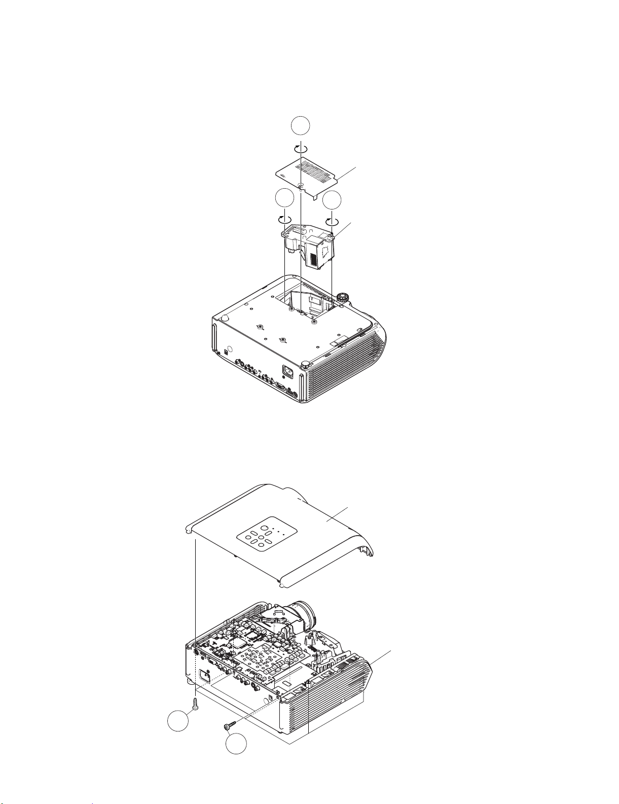
[2] Removing the top body
1. Remove 8 top body fixing screws to detach the Top body.
2
2
Lamp Unit
Top Body
Bottom Body
1
1
2 – 1
Page 21
XV-Z3100U/XV-Z3100/XV-Z3300/DT-510
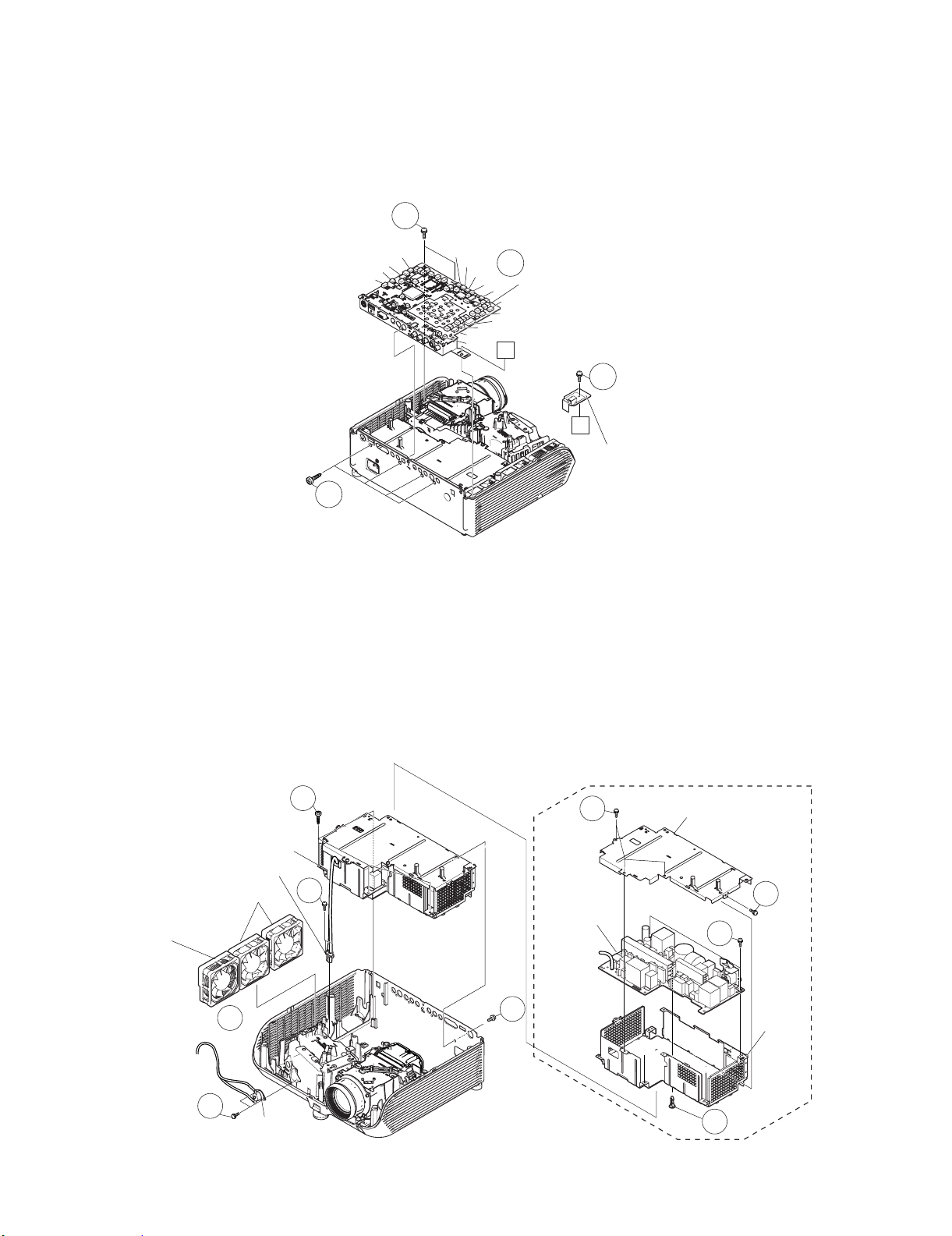
[3] Removing the main PWB unit and rear RC receiver PWB Unit
1. Remove 1 Rear RC receiver PWB fixing screws to detach the Rear RC receiver PWB unit.
2. Remove all connectors from the main PWB unit.
3. Remove 4 terminal fixing screws.
4. Remove 3 main PWB fixing screws to detach the main PWB unit.
4
[US]
[IR2]
[IR1]
[RC-F]
[CW]
[FA]
[MO]
[RC-R]
[SO]
[LF]
[FB]
[BB]
[EA]
2
[FD]
[FC]
A
MAIN PWB Unit
1
A
Rear RC
Receiver
3
PWB Unit
[4] Removing the fan and power/ballast ass'y
1. Remove 2 fans for the power supply ballast unit and 1 fan for the optical mechanism unit.
2. Remove 2 bimetal fixing screws to detach the bimetal.
3. Remove 2 lamp socket fixing screws to detach the lamp socket.
4. Remove 1 AC inlet fixing screw.
5. Remove 4 ballast unit fixing screws to detach the power/ballast ass'y.
6. Remove 4 ballast shield (upper) fixing screws to detach the ballast shield (upper).
7. Remove 2 ballast PWB fixing screws and 1 clip to detach the power/ballast ass'y from the ballast shield (lower).
Power /Ballast Ass'y
Lamp Socket
Fans for power supply
ballast unit
Fan for
optical
mechanism
unit
1
2
Bimetal
5
3
6
Ballast shield (upper)
6
Power/Ballast
Ass'y
7
4
Ballast
shield
(lower)
7
2 – 2
Page 22
XV-Z3100U/XV-Z3100/XV-Z3300/DT-510
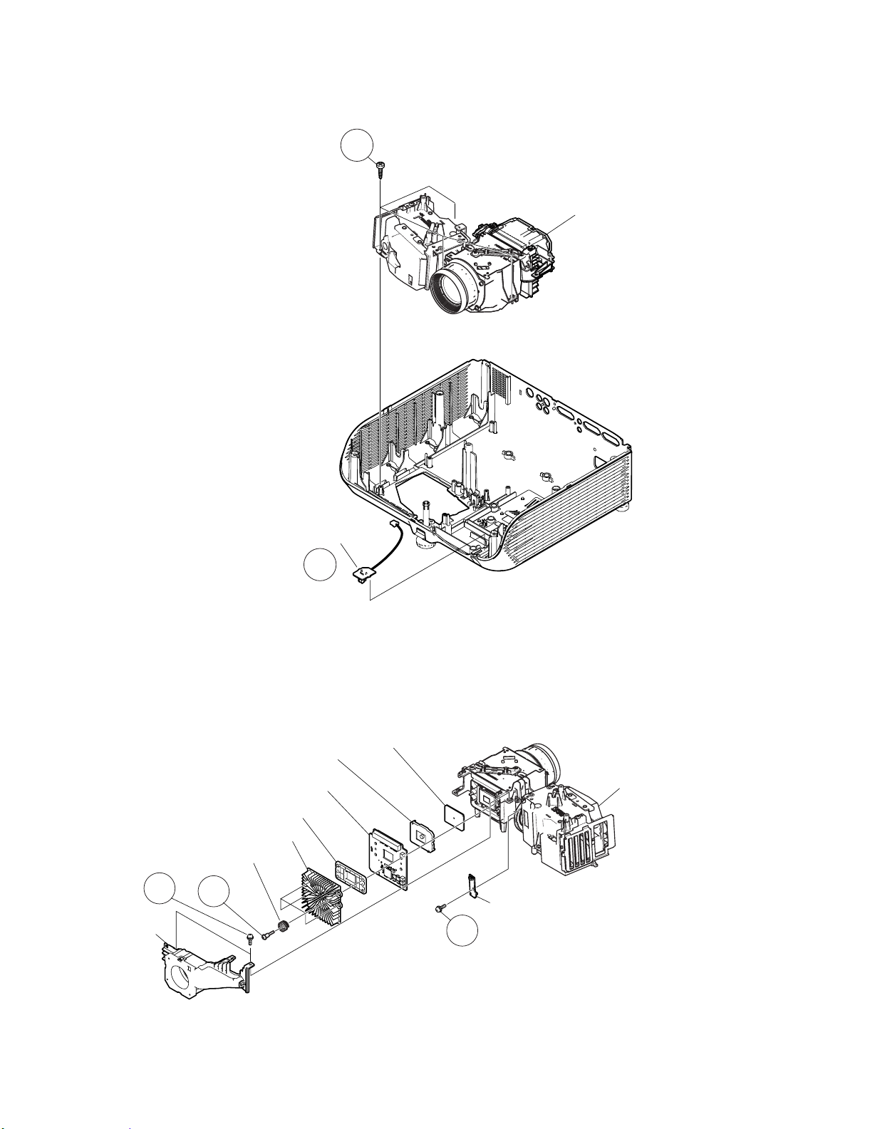
[5] Removing the optical mechanism unit and front RC receiver PWB
1. Remove 4 optical mechanism unit fixing screws to detach the optical mechanism unit.
2. Remove the RC PWB unit.
1
Optical Mechanism Unit
RC PWB Unit
2
[6] Removing the photosensor PWB unit, blower fan, DMD PWB, and DMD
1. Remove 1 photosensor PWB fixing screw to detach the photosensor PWB.
2. Remove 2 blower fan fixing screws to detach the blower fan.
3. Remove 4 DMD heatsink fixing screws to detach the DMD PWB unit and the DMD.
DMD
DMD socket
Optical Mechanism Unit
Blower fan
DMD heatsink
DMD spring
2
DMD PWB Unit
Backer plate
3
Photosensor PWB Unit
1
2 – 3
Page 23
XV-Z3100U/XV-Z3100/XV-Z3300/DT-510
XV-Z3100U
CHAPTER 3. THE OPTICAL UNIT OUTLINE
Service Manual
[1] THE OPTICAL UNIT OUTLINE
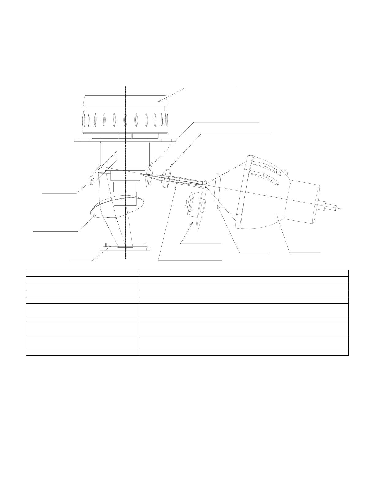
1. Layout for proper setup of the optical components and parts (top view) (Schematic diagram)
Projection lens
Illumination lens 2
Illumination lens 1
Reflection
mirror
Plastic Lens
Color wheel
DMD
Item Function
Lamp Light source. DC high-pressure mercury lamp.
UV/IR cut filter (UV GLASS) Filters out harmful UV and IR rays from the lamp.
Color wheel Splits light from the light source into R, G, B and W through a color filter.
Rod (ROD INTEGRATOR) Assures uniform light ray.
Illumination lens
(ILLUMINATION LENS 1, 2)
Reflection mirror Reflects light from the illumination lenses toward DMD.
Condenser Lens
(PLASTIC LENS)
DMD Turns the internal micromirror ON/OFF at the rate of color component of each dot of the input
Projection lens Enlarges light from DMD and projects it on a screen.
Focus light from the rod on DMD.
Condenses the light from the reflection mirror to the DMD and the pupil of the projection lens.
source to reflect light.
Rod Integrator
UV Glass
Lamp
3 – 1
Page 24
XV-Z3100U/XV-Z3100/XV-Z3300/DT-510
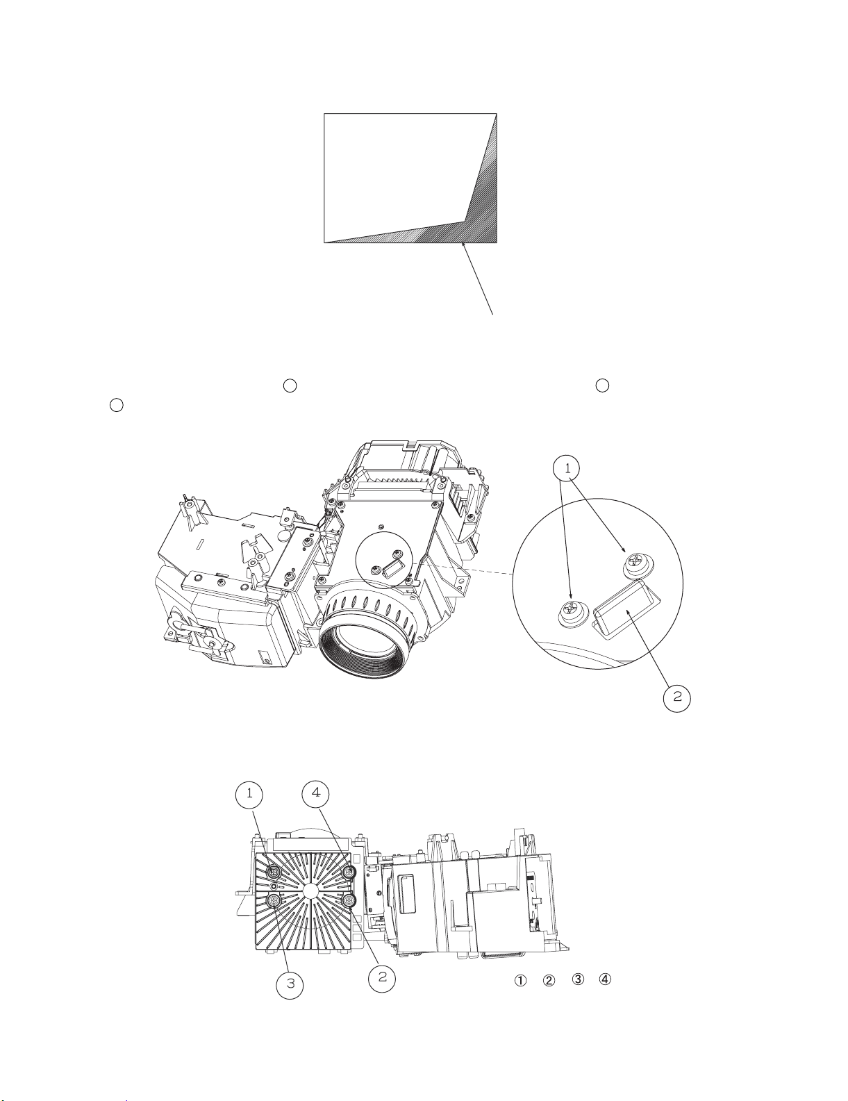
2. When the DMD unit has been replaced
If shading shown in Figure 1 appears on the screen after replacing DMD, turn the adjustment screw of the optical engine to adjust the lighting area of
DMD.
Fig. 1
Shading
1. Loosen the adjustment lever fixing screw . After adjusting the lighting area with the adjustment lever , tighten the adjustment lever fixing
screw .
1
When mounting DMD, tighten the 4 screws evenly.
1
2
Tightening order: →→→
Screw torque: 0.44 ± 0.05 N·m
3 – 2
Page 25
XV-Z3100U/XV-Z3100/XV-Z3300/DT-510
XV-Z3100U
CHAPTER 4. ELECTRICAL ADJUSTMENT
Service Manual
[1] ELECTRICAL ADJUSTMENT
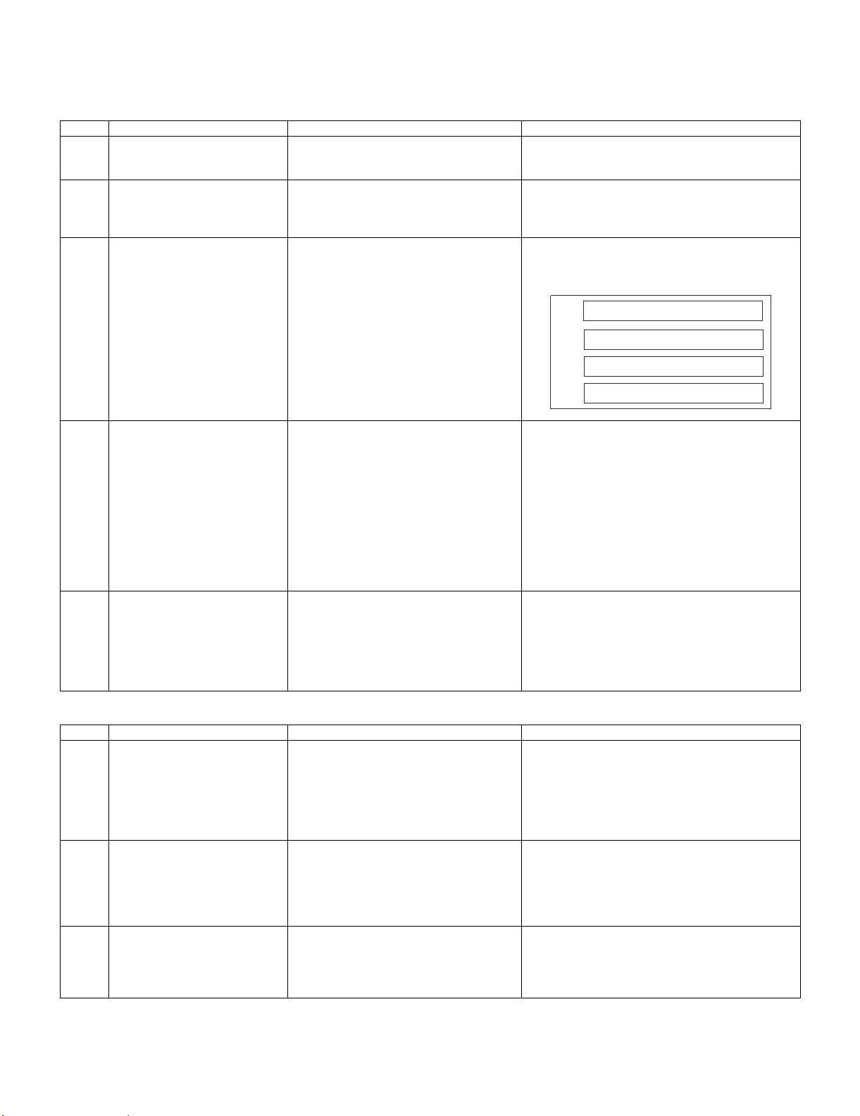
No. Adjusting point Adjusting conditions Adjusting procedure
1 EEPROM
initialization
2 Model setting (Process menu)
3 Adjustment of CW index 1. Signal input: Send 256 STEP color bar to
1. Turn on the power (with the lamp on) and
warm up the set for 15 minutes.
1. Select the following group and subject.
Group: CONFIRM
Subject: MODEL-SELECT
INPUT5.
(SVGA60Hz or XGA60Hz)
2. Select the following group and subject.
Group: ADJUST CW/Auto KS
Subject: CW-INDEX.
•Make the following settings.
Press S6213 to call the process mode and execute
"SS2" on SS menu.
1. Set as below.
XV-Z3100 : 1 (default)
XV-Z3300 : 2
DT-510 : 0
1. Adjust the lamp gradation patterns of RGBW so
that smooth patterns without noise appear.
W
R
G
B
4 R/G/B contrast adjustment
(manual or automatic)
5 White balance adjustment 1. Feed the component 75% gray signal to
1. Select the following group and subjects.
Group : ADJUST/AD
Subject : R-CONT
G-CONT
B-CONT
(Process GAMMA interlock)
2. Feed white signal with the amplitude level
of 96% (0.67Vpp) to INPUT5.
(SVGA60Hz or XGA60Hz)
INPUT5.
2. Select the following group and subjects.
Group : ADJUST
WB
Subject : R-GAIN
B-GAIN
1. Measure chromaticity of the 96% white wind pattern
using CA100.
2. On the screen where bit dropouts occur, raise the
values of R/G/B-Contrast. Adjust the values so that
bright red, green, and blue bit dropouts appear on
a black background; and amounts of change in x
value of R and y values of G/B become 100/1000
or more.
3. If adjustment is performed manually watching the
screen, make adjustment so that bright red, green,
and blue bit dropouts appear on more than half of
the screen.
1. So that the following chromaticity values are
obtained using CL200.
X value: 298 ± 5
Y value: 319 ± 5
Adjust R-GAIN and B-GAIN
Check items
No. Adjusting point Adjusting conditions Adjusting procedure
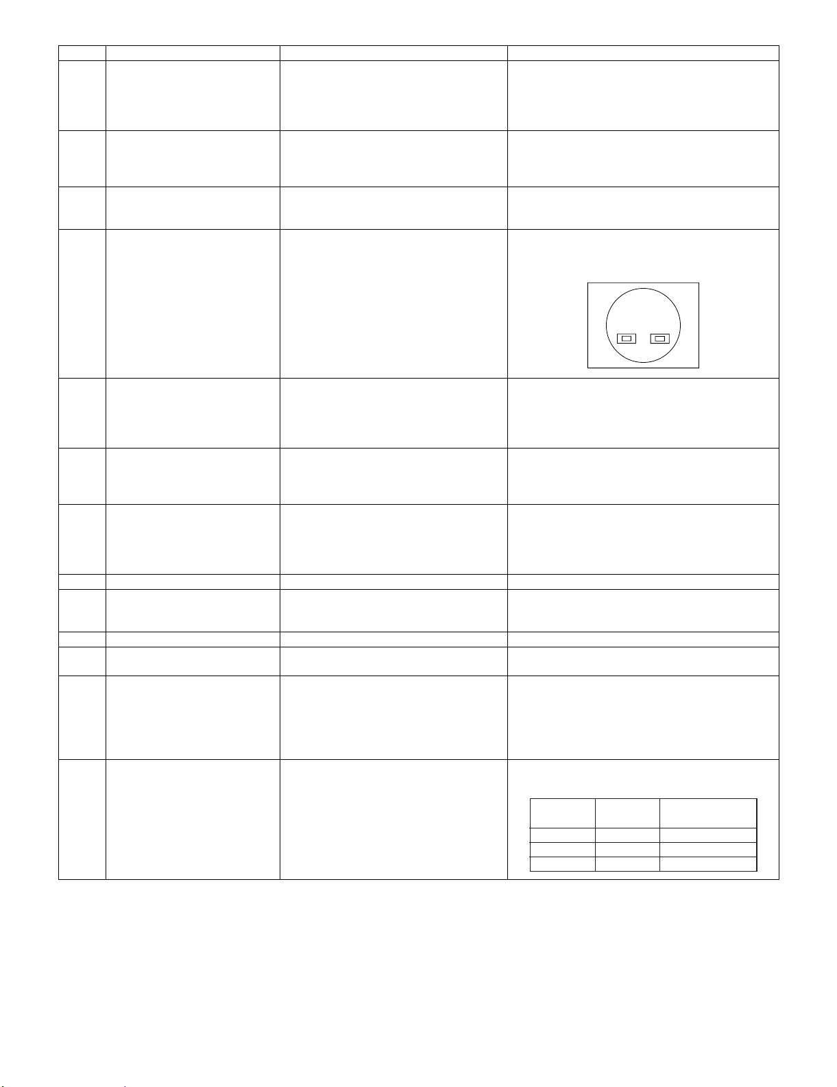
1 Adjustment of Component offset 1. Feed 10-step signal with 480P component
100% amplitude.
2. Select the following group and subjects.
Group : ADJUST/AD
Subject : C-R-OS
C-B-OS
(Process GAMMA interlock)
2 Adjustment of DLP Brightness 1. Select the following group and subject.
Group : CONFIRM/DLP
Subject :R-BLK
G-BLK
B-BLK
(Process GAMMA interlock)
3 Video Contrast adjustment 1. Feed NTSC 100% wind pattern signal.
(Signal with burst)
2. Select the following group and subjects.
Group : CONIRM/VIDEO
Subject : V-CONT
1. Check the fixed value.
C-R-OS : 257
C-B-OS : 256
1. Check the fixed value.
Fixed value : 252
1. Check the fixed value.
Fixed value : 134
4 – 1
Page 26
XV-Z3100U/XV-Z3100/XV-Z3300/DT-510
Destination Process Remote control
adjustment adjustment
USA SS4 Factory setting at 4
China SS6 Factory setting at 6
Others SS3 Factory setting at 3
No. Adjusting point Adjusting conditions Adjusting procedure
4 Adjustment of Video Brightness 1. Feed NTSC 100% wind pattern signal.
5 Adjustment of Video Tint 1. Feed split color bar.
6 Adjustment of Video color satura-
tion
7 RGB tone reproduction adjust-
ment
(Signal with burst)
2. Select the following group and subject.
Group : CONFIRM/VIDEO
Subject : V-BRIGHT
2. Select the following group and subject.
Group : CONFIRM/VIDEO
Subject : V-HUE
1. Select the following group and subject.
Group : CONFIRM/VIDEO
Subject : V-COLOR
1. Feed the SMPTE pattern signal. 1. Make sure the 100% and 95% white as well as the
1. Check the fixed value.
Fixed value : 68
1. Check the fixed value.
Fixed value : 128
1. Check the fixed value.
Fixed value : 139
0% and 5% black gradations are visible.
8 VIDEO white balance adjustment 1. Feed the 50% gray signal.
2. Select the following group and subjects.
Group :CONFIRM/VIDEO
Subject : V-R-OS
V-B-OS
9 White balance checking and
readjustment
10 Off-timer performance 1. Select the following group and subjects.
11 Thermistor performance checking 1. Heat the thermistor with a hair dryer. 1. Make sure that the temperature is indicated.
12 Auto sync performance checking 1. Feed the phase check pattern signal. 1. In the VGA, SVGA and XGA modes, make sure the
13 HDMI input operation 1. Feed HDMI video signal to INPUT6. 1. Check that images are projected correctly.
14 RS232C operation check 1. Connect the unit and a PC with the
15 Model name and version check 1. Select the following group.
16 Delivery settings 1. Make the following settings.
1. RGB Input
VIDEO Input
DTV Input
DVD Input
Group :CONFIRM/CHECK
Subject : TEMP-OFF
RS232C cable.
Group : INFO/VERSION.
1. V-R-OS is 130.
V-B-OS is 130.
Check that there is no deviation of white balance with
the monitor.
1. Select OFF from the process mode.
Make sure the off-timer starts with 5 minutes
onscreen and count one minute in one second.
And then indication is 0 minute, the power supply
of the set is cut off.
Clock, Phase, H-Pos and V-Pos settings can be
automatically adjusted.
1. Send a command from the PC, and check it func tions correctly.
1. The model name appears in the MODEL field, and
the firmware version in the VERSION field. Check
that they are correct.
MODEL : DT-510 (MODEL-SELECT=0)
MODEL : XV-Z3100 (MODEL-SELECT=1)
MODEL : XV-Z3300 (MODEL-SELECT=2)
* Writing a software program (before main PWB is mounted)
Use the DLP Composer Lite Ver. 6.0 or higher to download the firmware.
After writing the specified version of firmware to the PWB using the RS232C cable, check the version of the written firmware.
If no software program is written, all three LEDs light up in the chassis inspection process.
4 – 2
Page 27

XV-Z3100U/XV-Z3100/XV-Z3300/DT-510
Calling and quitting the process mode with the control keys on this model.
* Although it is possible for the process OUT to exit using the process menu, the IN/OUT toggle command is also available considering the existing
specification.
1) Calling and quitting
With the menu not displayed, press the "ENTER", "ENTER", "Right", "Left", "ENTER", "ENTER" and "MENU" keys on the remote control or on the
main unit.
2) Others
Press the S6213 process key (toggle) on the main PWB to call and quit the process menu.
NOTE: When adjusting in the process mode, set a signal with a vertical frequency of 60 Hz or no signal. (May not be properly adjusted with other sig-
nals.)
Resetting the lamp timer for this model
1) Resetting procedure
In Stand-by, run this command to clear the operating time of the lamp to 0 and turn on the power.
Press and hold " ", "ENTER", and "MENU", and then press the "STANDBY/ON" key of the set.
4 – 3
Page 28
XV-Z3100U/XV-Z3100/XV-Z3300/DT-510
[2] Adjustment mode process menu
1st Layer 2nd Layer Default
ADJUST CW/Auto KS CW-INDEX 120
CAL
K-SENS (127)
AD R-CONT 160
G-CONT 160
B-CONT 160
R-BRIGHT 127
G-BRIGHT 127
B-BRIGHT 127
C-R-OS 257
C-B-OS 256
WB R-GAIN 100
G-GAIN 100
B-GAIN 100
SS SS1 —
SS2 —
SS3 —
SS4 —
SS5 —
SS6 —
CONFIRM DLP R-BLK 252
G-BLK 252
B-BLK 252
S-R-OS 128
S-G-OS 128
S-B-OS 128
VIDEO V-CONT 134
V-BRIG HT 68
V-COLOR 139
V-HUE 128
V-R-OS 130
V-G-OS 128
V-B-OS 130
OFFSET-MODE 0
OFFSET-CONT 0
OFFSET-BRI 0
MODEL MODEL-SELECT 1
CHECK LED-CHK 0
TEMP-OFF —
INFO VERSION MODEL —
VER. —
PATTERN RGB 1
RGB50 1
CORSS 1
STEP 1
COLOR 1
CHR 1
LAMP CURRENT 0
HISTORY1 0
HISTORY2 0
HISTORY3 0
HISTORY4 0
TOTAL 0
TEMP/FAN TEMP1 —
TEMP2 —
FAN0 3
FAN1 3
FAN2 3
OTHER 232C 232C-MODE 1
HDCP HDCP-MODE 0
EXIT
4 – 4
Page 29
XV-Z3100U/XV-Z3100/XV-Z3300/DT-510
1. Adjustment of ballast unit output power (lamp power)
1. List of parts requiring adjustment
When replacing the following parts, adjust the ballast unit output power (lamp power).
Part name Ref No. Part code
1 Cement resistor R905 RR-FZA002WJZZ
2 Ballast Control PWB —— DUNTKD148WEF7
3 Ballast microprocessor IC7707 RH-iXB996WJZZQ
4 5V regulator IC7704 VHITA78L05F-1Y
5 PWM Controller IC7701 VHIM51995AF-1Y
2. Adjustment jigs
The following jigs are required for adjusting the ballast unit output power (lamp power).
Part name Part code Manufacturer
1 Adjustment jig (resistance load 25 Ω) RUNTZA018WJZZ Asahi Communication
2 Connecting cord (conversion cable) QCNWKA016WJZZ SMK
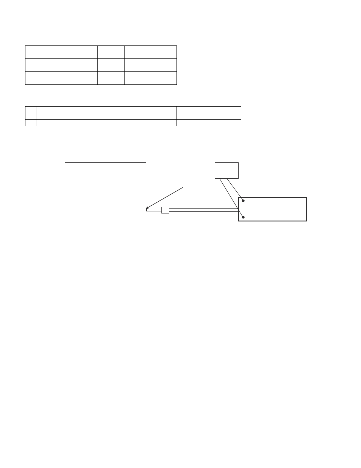
3. Ballast unit output power (lamp power) adjustment method
Adjust the ballast unit output power (lamp power) in the following method.
[Setting method]
XV-Z3100U
XV-Z3100
XV-Z3300
DT-510
Projector
Ballast Unit
Lamp Cable
Connecting Cord
(QCNWKA016WJZZ)
Tester
(Voltage)
TP1
Adjustment Jig
(RUNTZA018WJZZ)
TP2
2. Adjustment method
1) Unplug the ballast unit lamp cable of the projector from the lamp and connect the cable to the connecting cord
(QCNWKA016WJZZ).
2) Connect the connecting cord (QCNWKA016WJZZ) to the adjustment jig (RUNTZA018WJZZ).
3) Connect TP1 of the adjustment jig (RUNTZA018WJZZ) to the negative terminal of the tester and TP2 to the positive terminal.
4) Turn on the projector.
5) Check the Lamp setting to “Bright”.
6) Age the projector for 60 seconds or more.
7) Adjust the volume resistor (R7728) of the ballast control PWB (DUNTKD148WEF7) so that the voltage of the tester reaches 74± 0.5 V.
Adjustment value: 74±0.5 V
CAUTION: (1) Caution for electric shock: Do not touch the test points TP1 and TP2 of the adjustment jig when supplying power since a high voltage
and large current is applied to them.
(2) Caution for heat: Be careful that the resistance load of the adjustment jig produces a high temperature when supplying power.
(3) Connection of the lamp cable: Check that the lamp cable and connecting cord (QCNWKA016WJZZ) are connected securely.
Poor connection may cause smoking or ignition due to arc discharge.
4 – 5
Page 30
XV-Z3100U/XV-Z3100/XV-Z3300/DT-510
XV-Z3100U
CHAPTER 5. TROUBLE SHOOTING TABLE
Service Manual
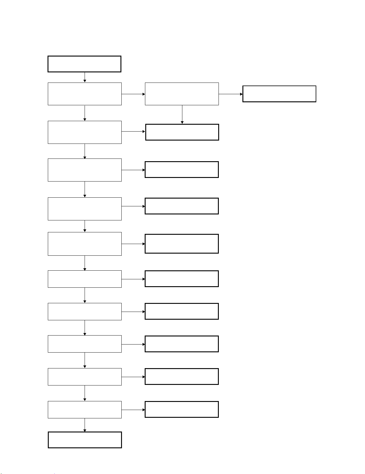
[1] TROUBLE SHOOTING TABLE
Checking the basic
operation
Does the power LED light
up or flash in red or green?
YES
Does the set function with
its keys or the remote
controller?
YES
Lamp does not turn on or it
turns off in a short time.
NO
Nothing is displayed or
white vertical line noise
appears.
NO
Colors are not displayed
normally. Color deviation
and color fluctuation occur.
NO
NO
NO
YES
YES
YES
Has P1705 come off or is it
loose?
NO
Go to "Main PWB check".
Go to "Checking the lamp
light-up".
Go to "DMD system
check".
Check PHOTO SENSOR
circuit.
YES
Fully insert the connector.
Is component input
displayed normally?
YES
Is RGB input displayed
normally?
YES
Is VIDEO input displayed
normally?
YES
Is S-VIDEO input
displayed normally?
YES
Is HDMI input displayed
correctly?
YES
END
NO
NO
NO
NO
NO
Go to "Component signal
check".
Go to "RGB signal
check".
Go to "VIDEO input
check".
Go to "S-VIDEO input
check".
Go to "HDMI input is nit
displayed".
5 – 1
Page 31

Main PWB check
XV-Z3100U/XV-Z3100/XV-Z3300/DT-510
Is 6 V applied to TL1731
and 13 V to TL1734?
YES
Is approx. 6 V applied to
TL1710?
YES
Is 1.5 V applied to
TL1703?
YES
Is 3.3 V applied to
TL1704?
YES
Is 1.5 V applied to
TL1705?
YES
Is 2.5 V applied to
TL1706?
YES
Is 5 V applied to TL1708?
YES
NO
Go to "Power supply
ballast PWB check".
NO
Check IC1713 and
peripheral circuits.
NO
Check IC1701 and
peripheral circuits.
NO
Check IC1702 and
peripheral circuits.
NO
Check IC1704 and
peripheral circuits.
NO
Check IC1703 and
peripheral circuits.
NO
Check IC1711 and
peripheral circuits.
Is 3.3 V applied to pin(1)
of IC1714?
YES
Check IC1714 and
peripheral circuits.
Is 3.18 V applied to pin(1)
of IC2204?
YES
Check IC2204, 2207, 2208
and peripheral circuits.
Is 3.3 V applied to pin(1)
of S2001?
YES
Check that it is set to the N
side. Or remove S2001.
NO
NO
NO
Is 3.3 V applied to
TL1707?
Is 12 V applied to
TL1709?
YES
YES
NO
Check IC1705 and
peripheral circuits.
NO
Check IC1712 and
peripheral circuits.
5 – 2
Are rectangular waves of
50 MHz and 48 MHz
supplied to pins (8) and (7)
of IC2206 respectively?
YES
Check IC2206 and
peripheral circuits.
Check IC2001, IC2002,
IC2202, IC2203 and
peripheral circuits.
NO
Page 32

XV-Z3100U/XV-Z3100/XV-Z3300/DT-510
DMD system check
Check P6001 for breakage
and solder crack and
peripheral resistance for
solder crack.
Check SC9001 for
breakage and solder crack.
Is there any vertical stripe
(block noise) on the
screen?
NO
Is approx. 7 V applied to
TL9303?
YES
Is approx. 26 V applied to
TL9301?
YES
Is approx. -26 V applied to
TL9302?
YES
YES
NO
NO
NO
Check IC9301 and
peripheral circuits.
The main PWB and DMD
PWB are in poor contact.
Check the contact surface
for dirt and smear.
Check the DMD connector
for breakage.
Reassemble the DMD,
optical mechanism, and
DMD PWB.
5 – 3
Page 33

Power supply PWB
check
XV-Z3100U/XV-Z3100/XV-Z3300/DT-510
Is 6 V applied to pins (7)
and (8) of the connector
P704?
YES
Is 13 V applied to pins (3)
and (4) of the connector
P704?
YES
Does the lamp turn on?
YES
Check the main PWB.
Are connectors P704 and
CN901 fully inserted?
NO
NO
NO
NO
1
Check peripheral circuits of
IC703.
Securely insert the
connectors.
YES
Is DC voltage of 380 V
applied to both ends of
C704?
YES
Is R766 in the OPEN
status?
YES
Check circuits R766 and
after or replace R766.
NO
NO
Is pin (11) of the connector
P704 at "H"?
YES
Check peripheral circuits
of IC902.
Is LAMP-COM signal
properly sent to pin (14) of
the connector P704?
(Refer to the waveform
1
chart .)
YES
Are GATE waveforms of
Q901 appropriate?
(See waveform diagram .)
8
NO
NO
NO
Check the main PWB.
Check the main PWB.
Check the ballast PWB.
5 – 4
Page 34

XV-Z3100U/XV-Z3100/XV-Z3300/DT-510
1
Are connectorsP701 and
P702 fully inserted?
YES
Is AC voltage between 100
− 240 V applied to both
ends of C707?
YES
Is the bimetal broken?
(Connection between 1 and
2 of P702)
YES
Is R717 open?
YES
Check that P704 connector
pin (11) is at "H". Replace
R717.
NO
NO
NO
NO
Securely insert the connectors.
Replace F701.
Press the red button on the
bimetal.
Is R705 open?
YES
Replace F705.
Check that the power
supply FAN FB and FC
are not stopped.
NO
Check peripheral circuits of
IC703.
5 – 5
Page 35

Checking the lamp
light-up
XV-Z3100U/XV-Z3100/XV-Z3300/DT-510
Does the lamp turn on
when the power is turned
on?
NO
Is the lamp tight in the
socket?
NO
Has the FPC cable to
SC6001 come off or is it
loose?
NO
Is rotating sound of the
color wheel heard?
YES
Is approx. 0.7 V applied to
TL1740?
YES
YES
YES
YES
NO
NO
Go to "Check when the
lamp turns off soon after
turning on".
Securely insert the
connectors.
Securely insert the
connectors.
Check IC6001 and
peripheral circuits. (Refer
to the waveform chart .)
2
Check IC1715 and
peripheral circuits. (Refer
to the waveform chart .)
1
YES
Replace the color wheel.
Has the harness connected
to P702 on the power
supply unit come off, or is it
loose? Otherwise, is it
broken?
NO
Dose the lamp turn on after
the replacement?
NO
Is 340 VDC applied to both
ends of C914?
YES
Is D911 or D913 shortcircuited?
NO
Is D914or D910 shortcircuited?
YES
YES
NO
YES
YES
Fully insert the connectors
or replace the harnesses.
Replace the lamp.
Go to "Power supply PWB
check".
Replace both D911 and
D913.
Replace D914 or D910,
whichever is short-circuited.
5 – 6
Page 36

XV-Z3100U/XV-Z3100/XV-Z3300/DT-510
Check when the lamp turns
off soon after turning on
Have connectors P1702,
P1721, P1722, P1723 and
P1724 come off or are they
loose?
NO
Is each cooling fan
rotating?
YES
Is approx. 3 V applied to
TL1712?
YES
Is 12 V applied to TL1709?
YES
Is 2.5 V applied to
TL1706?
YES
YES
NO
NO
NO
NO
Securely insert the
connectors.
Check the cooling fan.
Check peripheral circuits of
Q1714.
Check IC1712, IC6001 and
peripheral circuits.
Is 3.3 V applied to TL1704?
NO
Check IC1704 and
peripheral circuits.
YES
Go to "DMD system check".
Check IC1706 and
peripheral circuits.
Is 5 V applied to TL1708?
YES
Is 5 V applied to TL1726?
YES
Is the signal of 180 Hz
sent to TL1727?(When
vertical frequency of the
input signal is 60 Hz)
YES
Is the signal of 180 Hz
sent to TL1740? (When
vertical frequency of the
input signal is 60 Hz)
YES
Check the power supply
ballast PWB.
NO
NO
NO
NO
Check IC1711 and
peripheral circuits.
Is 5 V applied to TL1726
with P1702 removed?
YES
Check PHOTO SENSOR
PWB.
Check IC1701 and
peripheral circuits.
NO
Check connection of
FB1716.
5 – 7
Page 37

RGB signal check
Send RGB signal from
INPUT 5.
Select INPUT 5 using keys
on the main unit or the
remote control.
YES
XV-Z3100U/XV-Z3100/XV-Z3300/DT-510
Is image displayed
normally?
NO
Are picture signals sent to
TL3001, TL3002 and
TL3003?
YES
Is 3.3V applied to TL1707?
YES
Is 3.3V applied to pin(5) of
Q3002?
YES
Is 3.5V applied to TL1704?
YES
Check IC3001 and
peripheral circuits.
YES
NO
NO
NO
NO
End
Check Q4003, Q4004,
Q4005 and the peripheral
circuits.
Check IC1705 and
peripheral circuits.
Check Q3002 and
peripheral circuits.
Check IC1702 and
peripheral circuits.
5 – 8
Page 38

XV-Z3100U/XV-Z3100/XV-Z3300/DT-510
Component signal
check
Send component signal of
1080i (or 720P) from
INPUT 1 or INPUT 2.
Select INPUT 1 or INPUT 2
using keys on the main unit
or the remote control.
YES
Is image displayed
normally?
NO
Are picture signals sent to
TL3008, TL3007, and
TL3006?
YES
Is 3.3V applied to TL1707?
YES
Is 3.3V applied to pin(5) of
Q3002?
YES
Is 3.3V applied to TL1704?
YES
Check IC3001 and
peripheral circuits.
YES
NO
NO
NO
NO
End
Check IC4002 and the
peripheral circuits.
Check IC1705 and
peripheral circuits.
Check Q3002 and
peripheral circuits.
Check IC1702 and
peripheral circuits.
5 – 9
Page 39

XV-Z3100U/XV-Z3100/XV-Z3300/DT-510
S-VIDEO (INPUT 3)
check
Send S-Video signal (color
signal) from INPUT 3.
Select INPUT 3 using keys
on the main unit or the
remote control.
Is image displayed
normally?
NO
Is image displayed in black
and white?
NO
Is S-VIDEO signal (Y) sent
to C3306?
YES
YES
YES
NO
End
Check S-VIDEO terminal
and peripheral circuits of
Q3302.
Check S-VIDEO terminal
and peripheral circuits of
Q3301.
End
VIDEO (INPUT 4) check
Send VIDEO signal from
INPUT 4. Use buttons on
the main unit or the remote
control to select INPUT 4.
YES
Is image displayed
normally?
Is 1.8 V applied to
TL3310?
YES
Is 3.3 V applied to pin(3) of
IC3303?
YES
Is 1.5 V applied to pin(2) of
IC3301?
YES
End
NO
NO
NO
Check VIDEO terminal and
peripheral circuits of
Q3303.
Check IC3303 and
peripheral circuits.
Check Q3305 and
peripheral circuits.
Check IC1705 and
peripheral circuits.
NO
Is VIDEO signal sent to
C3320?
NO
YES
5 – 10
Page 40

XV-Z3100U/XV-Z3100/XV-Z3300/DT-510
HDMI input is not
displayed.
Do pin 19 of HDMI terminal
become to "H" (5V) when
connecting a cable?
YES
Is TM DS signal fed to
Rx0, Rx1, Rx2, and Rxc of
IC3901?
YES
Are HSync, VSync and
RGB data sent from
IC3901?
YES
Check peripheral circuits
of IC3701.
NO
NO
NO
Check Q3905 and HPD
line of IC6202.
Is IC3902 accessed via I2C
and data read?
NO
Check IC3902 and
peripheral circuits of HDMI
terminal.
Check cables, too.
Check peripheral circuits of
IC3901.
YES
Check the setting of DVD
device (signal source).
5 – 11
Page 41

— MEMO —
XV-Z3100U/XV-Z3100/XV-Z3300/DT-510
5 – 12
Page 42

XV-Z3100U/XV-Z3100/XV-Z3300/DT-510
XV-Z3100U
CHAPTER 6. BLOCK DIAGRAM/OVERALL WIRING DIAGRAM
Service Manual
[1] BLOCK DIAGRAM
BLOCK DIAGRAM
,
+
*
)
(
'
&
%
$
#
6 – 1
Page 43

XV-Z3100U/XV-Z3100/XV-Z3300/DT-510
6 – 2
Page 44

XV-Z3100U/XV-Z3100/XV-Z3300/DT-510
M
[2] OVERALL WIRING DIAGRAM
OVERALL WIRING DIAGRAM
,
+
*
)
(
R/C UNIT
DUNTKD164WEF7
N0364TA
VENTILATEFAN
EXHAUSTFAN
EXHAUSTFAN
EXHAUSTFAN
LF-SW
QCNW-D515WJQZ
TEMPSENSOR
RH-HXA025WJPZ
N0364TA
P1121
RC
B+5VA
1
R/C
2
GND
3
QCNW-D517WJQZ
LAMPFAN
N0364TA
EXHAUSTFAN
N0464TA
EXHAUSTFAN
N0364TA
EXHAUSTFAN
N0263TA
N0363TA
N0364TA
P6502
P6503
P1721
P1722
P1723
P1724
P1701
RCS_PULL
B+3.3VA
FA
1
+B
2
GND
LOCK
3
FB
1
+B
2
GND
3
LOCK
FD
1
+B
2
GND
3
NC
4
LOCK
FC
1
+B
2
GND
3
LOCK
LF
1
RCS
2
TH
1
TEMP1
2
NC
3
RA
B+5V
1
R/C
2
GND
3
D
N0174FJ
N0564TA
N0264TA
P6504
P6506
IRIS_1(+)
IRIS_1(-)
P6507
IRIS_2(-)
IRIS_2(+)
TRIGGER
RB
B+5V
1
R/C
2
GND
3
GND
4
5
1
2
1
2
RB
1
2
3
'
REAR R/C UNIT
DUNTKD577WEF0/F2
4
N0564TA
P1551
B+5V
R/C
GND
GND
TRIGGER
5
IRIS1MOTOR
QCNW-E299WJQZ
&
IRIS1MOTOR
%
BALLAST CONTROL UNIT
DUNTKD148WEF7
BA
1
2
3LN
1
2
P702
N0269GE
P701
AA004WJ
AC-INLET
$
BI-METAL
QCNW-D575WJPZ
GND220V3PT4GND5TMP6VIN7IL8VL9SCP10CST11P_SW
1
BALLAST UNIT
DUNTKD147WEG4
121314151617181920
14
LAMP-COM
12
ECO
10
GND
8
6V
6
GND
4
13V
GND
2
GND21LIGHT22ECO23LAMP
MA114WJ
P704
L-POW/SYNC
ECO/LPS
GND
B+6V
GND
B+13V
GND
EA
NA071WJ
13
NLIGHT
11
PFC_ON/OFF
9
GND
7
B+6V
5
GND
3
B+13V
1
P1705
GND
13
N-LIGHT
11
P-CON
9
GND
QCNW-D518WJQZ
7
6V
5
GND
3
13V
1
GND
14
12
10
8
6
4
2
6 – 3
Page 45

XV-Z3100U/XV-Z3100/XV-Z3300/DT-510
MAIN UNIT
DUNTKD575FMF3
139
GND
137
B+12V
135
B+12V
133
GND
131
DADADR0
129
DADADR1
127
DADADR2
125
DADADR3
123
GND
121
DAMSTRB
119
DMD_OEZ
117
DADSEL0
115
DADSEL1
113
GND
111
DMDMD0
109
DMDMD1
107
EXT_ARSTZ
105
SCPENZ
103
GND
101
SPCDO
99
SCPCK
97
DADINT
95
SCPDI
93
GND
91
GND
89
GND
87
GND
85
DMD_CSZ0
83
BINSEL0
81
NC
79
GND
77
DDA0N
75
DDA0P
73
DDA1N
71
DDA1P
DDA2N
69
DDA2P
67
65
DDA3N
63
DDA3P
DDA4N
61
DDA4P
59
57
DDA5N
55
DDA5P
53
DDA6N
51
DDA6P
49
DDA7N
47
DDA7P
45
SCAN
43
SCAP
DCKAN
41
39
DCKAP
37
DDA8N
35
DDA8P
33
DDA9N
31
DDA9P
29
DDA10N
27
DDA10P
25
DDA11N
23
DDA11P
21
DDA12N
19
DDA12P
17
DDA13N
15
DDA13P
13
DDA14N
11
DDA14P
DDA15N
9
DDA15P
7
B+3.3V_DC
5
B+3.3V_DC
3
1
GND
142
P6001
141
B+3.3V_DC
B+3.3V_DC
B+3.3VA
DDB15N
DDB15P
DDB14N
DDB14P
DDB13N
DDB13P
DDB12N
DDB12P
DDB11N
DDB11P
DDB10N
DDB10P
ZA018WJ
140
GND
138
B+12V
136
B+12V
134
GND
132
130
128
126
124
122
120
118
116
114
112
110
108
DDB9N
106
DDB9P
104
DDB8N
102
DDB8P
100
SCBN
98
SCBP
96
DCKBN
94
DCKBP
92
DDB7N
90
DDB7P
88
DDB6N
86
DDB6P
84
DDB5N
82
DDB5P
80
DDB4N
78
DDB4P
76
DDB3N
74
DDB3P
72
DDB2N
70
DDB2P
68
DDB1N
DDB1P
66
DDB0N
64
62
DDB0P
60
GND
58
GND
56
GND
54
GND
52
GND
50
GND
48
GND
GND
46
GND
44
42
GND
GND
40
GND
38
GND
36
GND
34
GND
32
GND
30
GND
28
GND
26
GND
24
GND
22
GND
20
GND
18
GND
16
GND
14
TEMP0
12
10
GND
8
6
4
GND
2
DMD UNIT
DUNTKD578WEF1
DMD
N0363TA
CW
P1702
B+5VA
1
CWINDEX
2
GND
3
WA500WJ
SC6001
MO
1
CWY1
2
CWY2
3
CWY3
4
CWCTR
QCNW-C221WJQZ
N0363TA
P1101
B+5VA
CWINDEX
COLOR WHEEL
6 – 4
CW
1
2
GND
3
SENSOR UNIT
DUNTKC141WEF7
Page 46

XV-Z3100U/XV-Z3100/XV-Z3300/DT-510
XV-Z3100U
CHAPTER 7. PRINTED WIRING BOARD
[1] MAIN Unit
MAIN Unit (SIDE-A)
J
I
H
Service Manual
G
F
E
D
C
B
A
1
23
4567 910
8
7 – 1
Page 47

XV-Z3100U/XV-Z3100/XV-Z3300/DT-510
11 1312 14 15 16 18 1917
7 – 2
Page 48

XV-Z3100U/XV-Z3100/XV-Z3300/DT-510
MAIN Unit (Chip SIDE-A)
J
I
H
G
F
E
D
C
B
A
1
23
4567 910
8
7 – 3
Page 49

XV-Z3100U/XV-Z3100/XV-Z3300/DT-510
11 1312 14 15 16 18 1917
7 – 4
Page 50

XV-Z3100U/XV-Z3100/XV-Z3300/DT-510
MAIN Unit (SIDE-B)
J
I
H
G
F
E
D
C
B
A
1
23
4567 910
8
7 – 5
Page 51

XV-Z3100U/XV-Z3100/XV-Z3300/DT-510
11 1312 14 15 16 18 1917
7 – 6
Page 52

XV-Z3100U/XV-Z3100/XV-Z3300/DT-510
MAIN Unit (Chip SIDE-B)
J
I
H
G
F
E
D
C
B
A
1
23
4567 910
8
7 – 7
Page 53

XV-Z3100U/XV-Z3100/XV-Z3300/DT-510
11 1312 14 15 16 18 1917
7 – 8
Page 54

XV-Z3100U/XV-Z3100/XV-Z3300/DT-510
[2] DMD Unit
J
I
H
G
F
E
D
C
B
DMD Unit (SIDE-A)
A
1
23
DMD Unit (Chip SIDE-A)
4567 910
8
7 – 9
Page 55

XV-Z3100U/XV-Z3100/XV-Z3300/DT-510
J
I
H
G
F
DMD Unit (SIDE-B)
E
D
C
B
A
1
23
4567 910
8
7 – 10
Page 56

XV-Z3100U/XV-Z3100/XV-Z3300/DT-510
[3] BALLAST POWER Unit
BALLAST POWER Unit (SIDE-A)
J
I
H
G
F
E
D
C
B
A
1
23
4567 910
8
7 – 11
Page 57

XV-Z3100U/XV-Z3100/XV-Z3300/DT-510
11 1312 14 15 16 18 1917
7 – 12
Page 58

XV-Z3100U/XV-Z3100/XV-Z3300/DT-510
BALLAST POWER Unit (SIDE-B)
J
I
H
G
F
E
D
C
B
A
1
23
4567 910
8
7 – 13
Page 59

XV-Z3100U/XV-Z3100/XV-Z3300/DT-510
11 1312 14 15 16 18 1917
7 – 14
Page 60

XV-Z3100U/XV-Z3100/XV-Z3300/DT-510
BALLAST POWER Unit (Chip SIDE-B)
J
I
H
G
F
E
D
C
B
A
1
23
4567 910
8
7 – 15
Page 61

XV-Z3100U/XV-Z3100/XV-Z3300/DT-510
11 1312 14 15 16 18 1917
7 – 16
Page 62

XV-Z3100U/XV-Z3100/XV-Z3300/DT-510
[4] BALLAST CONTROL Unit
J
I
H
G
BALLAST CONTROL Unit (SIDE-A)
F
E
D
C
B
BALLAST CONTROL Unit (Chip SIDE-A)
A
1
23
4567 910
8
7 – 17
Page 63

XV-Z3100U/XV-Z3100/XV-Z3300/DT-510
J
I
H
G
BALLAST CONTROL Unit (SIDE-B )
F
E
D
C
B
BALLAST CONTROL Unit (Chip SIDE-B)
A
1
23
4567 910
8
7 – 18
Page 64

XV-Z3100U/XV-Z3100/XV-Z3300/DT-510
[5] PHOTOSENSOR Unit
J
I
H
PHOTO SENSOR Unit (SIDE-A)
G
F
E
D
C
B
PHOTO SENSOR Unit (SIDE-B)
A
PHOTO SENSOR Unit (Chip SIDE-B)
1
23
4567 910
8
7 – 19
Page 65

[6] FRONT R/C RECEIVER Unit
J
I
H
G
XV-Z3100U/XV-Z3100/XV-Z3300/DT-510
FRONT R/C RECEIVER Unit (SIDE-A)
F
E
D
C
B
FRONT R/C RECEIVER Unit (Chip SIDE-A)
A
1
23
4567 910
8
7 – 20
Page 66

XV-Z3100U/XV-Z3100/XV-Z3300/DT-510
J
I
H
G
FRONT R/C RECEIVER Unit (SIDE-B)
F
E
D
C
B
A
1
23
FRONT R/C RECEIVER Unit (Chip SIDE-B)
4567 910
8
7 – 21
Page 67

XV-Z3100U/XV-Z3100/XV-Z3300/DT-510
Rear RC Receiver Unit (Chip SIDE-A)
Rear RC Receiver Unit (SIDE-B)
Rear RC Receiver Unit (SIDE-A)
1
23
4567 910
8
J
A
B
C
D
E
F
G
H
I
[7] REAR R/C RECEIVER Unit
7 – 22
Page 68

XV-Z3100U/XV-Z3100/XV-Z3300/DT-510
XV-Z3100U
CHAPTER 8. WAVEFORMS
[1] WAVEFORMS
Service Manual
1 TL1740
L-POW/SYNC
H:2msec
V:1V
Colour Bar
4 TL3010
TE8200_HS
H:10µsec
V:1V
XGA60Hz
2 TL6004
CWY1
H:400µsec
V:2V
Colour Bar
5 TL3009
TE8200_VS
H:4msec
V:1V
XGA60Hz
3 TL1727
CWINDEX
H:4msec
V:1V
Colour Bar
6 TL3313
VHS
H:40µsec
V:1V
Colour Bar
7 TL3312
VVS
H:4msec
V:1V
Colour Bar
8 Q901,Q903(GATE)
BALAST CONTROL
H:4µsec
V:100V
Colour Bar
8 – 1
Page 69

XV-Z3100U
CHAPTER 9. SCHEMATIC DIAGRAM
[1] DESCRIPTION OF SCHEMATIC DIAGRAM
XV-Z3100U/XV-Z3100/XV-Z3300/DT-510
Service Manual
DESCRIPTION OF
SCHEMATIC DIAGRAM
VOLTAGE MEASUREMENT CONDITION:
1. Voltages at test points are measured at the
supply voltage of AC 220V. Signals are fed by a color
bar signal generator for servicing purpose and the
above voltages are measured with a 20k ohm/V tester.
WAVEFORM MEASUREMENT CONDITION:
1. Waveforms at test points are observed at the supply
voltage of AC 220V. Signals are fed by a color bar
signal generator for servicing purpose.
INDICATION OF RESISTOR & CAPACITOR:
RESISTOR
1. The unit of resistance “Ω” is omitted.
(K=kΩ=1000 Ω,M=MΩ).
2. All resistors are ± 5%, unless otherwise noted.
(J= ± 5%, F= ± 1%, D= ± 0.5%)
3. All resistors are 1/10W, unless otherwise noted.
4. All resistors are Carbon type, unless otherwise noted.
C
: Solid
S
: Oxide Film
N
: Metal Coating
CAPACITOR
1. All capacitors are µF, unless otherwise noted.
(P=pF=µµF).
2. All capacitors are 50V, unless otherwise noted.
3. All capacitors are Ceramic type, unless otherwise
noted.
(ML): Mylar (TA): Tantalum
(PF): Polypro Film (ST): Styrol
CAUTION:
This circuit diagram is original one, therefore there may be a
slight difference from yours.
SAFETY NOTES:
1.DISCONNECT THE AC PLUG FROM THE AC
OUTLET BEFORE REPLACING PARTS.
2.SEMICONDUCTOR HEAT SINKS SHOULD BE
REGARDED AS POTENTIAL SHOCK HAZARDS
WHEN THE CHASSIS IS OPERATING.
IMPORTANT SAFETY NOTICE:
PARTS MARKED WITH “ " ( ) A R E
IMPORTANT FOR MAINTAINING THE SAFETY OF
THE SET. BE SURE TO REPLACE THESE PARTS
WITH SPECIFIED ONES FOR MAINTAINING THE
SAFETY AND PERFORMANCE OF THE SET.
W
: Cement
T
: Special
BESCHREIBUNG DES
SCHEMATISCHEN SCHALTPLANS
SPANNUNGSMESSUNGEN:
1. Spannungen an den Prüfpunkten werden bei einer
Netzspannung von 220V gemessen, Signale werden
für die Wartung mit einem Farbbalken-Signal generator
zugeführt, und Spannungen werden mit einem
Meßinstrument (20 kΩ/V) ermittelt.
SIGNALFORMMESSUNGEN:
1. Die Wellenformen an den Testpunkten werden bei einer
Netzspannung von 220V verfolgt. Signale werden für
die Wartung mit einem Farbbalken-Signal generator
zugeführt.
BEZEICHNUNG DES WIDERSTANDS UND
KONDENSATORS:
WIDERSTAND
1. Die Widerstandseinheit “Ω” wird weggelassen.
(K=kΩ=1000 Ω,M=MΩ)
2. Alle Widerstände haben ± 5%, sofern nicht anders
angegeben.(J= ± 5%, F= ± 1%, D= ± 0.5%)
3. Alle Widerstände haben 1/10W, sofern nicht anders
angegeben.
4. Alle Widerstände sind Kohletyp, sofern nicht anders
angegeben.
C
: Solid
S
: Oxide Film
N
: Metal Coating
KONDENSATOR
1. Die Kapazitätseinheit ist µF, sofern nicht anders
angegeben. (P=pF=µµF).
2. Alle Kondensatoren haben 50V, sofern nicht anders
angegeben.
3. Alle Kondensatoren sind Keramiktyp, sofern nicht
anders angegeben.
(ML): Mylar (TA): Tantal
(PF): Polyprofilm (ST): Styrol
ACHTUNG:
Bei diesem Schaltplan handelt es sich um den ursprünglichen.
Esönnen daher geringfügige Unterschiede zu dem lhrem bestehen.
SICHERHEITSANMERKUNGEN:
1. VOR DEM AUSWECHSELN VON TEILEN MUSS UNBEDINGT
NETZSTECKER AUS DER NETZSTECKDOSE GEZOGEN WERDEN.
2. DIE WARMEABLEITER DER HALBLEITER SOLLTEN BEIM
BETRIEB DES CHASSIS ALS MÖGLICHE URSACHEN VON
GEFÄHRLICHEN ELEKTRISCHEN SCHLÄGEN BETRACHTET
WERDEN.
WICHTIGE SICHERHEITSANMERKUNGEN:
MIT “ ”( )BEZEICHNETEN TEILE SIND
BESONDERS WICHTIG FÜR DIEAUFRECHTERHALTUNG
DER SICHERHEIT . BEIM WECHDIESER TEILE SOLLTEN
DIE VORGESCHRIEBENEN TEILE IMMER VERWENDET
WERDEN, UM SOWOHL DIE SICHERHEIT ALS AUCH DIE
LEISTUNG DES GERÄTES AUFRECHTZUERHALTEN.
W
: Cement
T
: Special
9 – 1
Page 70

XV-Z3100U/XV-Z3100/XV-Z3300/DT-510
,
#
$
%
&
'
(
)
*
+
MAIN Unit-1/11
[2] SCHEMATIC DIAGRAM
9 – 2
Page 71

XV-Z3100U/XV-Z3100/XV-Z3300/DT-510
9 – 3
Page 72

XV-Z3100U/XV-Z3100/XV-Z3300/DT-510
MAIN Unit-2/11
,
+
*
)
(
'
&
%
$
#
9 – 4
Page 73

XV-Z3100U/XV-Z3100/XV-Z3300/DT-510
9 – 5
Page 74

XV-Z3100U/XV-Z3100/XV-Z3300/DT-510
MAIN Unit-3/11
,
+
*
)
(
'
&
%
$
#
9 – 6
Page 75

XV-Z3100U/XV-Z3100/XV-Z3300/DT-510
9 – 7
Page 76

XV-Z3100U/XV-Z3100/XV-Z3300/DT-510
MAIN Unit-4/11
,
+
*
)
(
'
&
%
$
#
9 – 8
Page 77

XV-Z3100U/XV-Z3100/XV-Z3300/DT-510
9 – 9
Page 78

XV-Z3100U/XV-Z3100/XV-Z3300/DT-510
MAIN Unit-5/11
,
+
*
)
(
'
&
%
$
#
9 – 10
Page 79

XV-Z3100U/XV-Z3100/XV-Z3300/DT-510
9 – 11
Page 80

XV-Z3100U/XV-Z3100/XV-Z3300/DT-510
,
#
$
%
&
'
(
)
*
+
MAIN Unit-6/11
9 – 12
Page 81

XV-Z3100U/XV-Z3100/XV-Z3300/DT-510
9 – 13
Page 82

XV-Z3100U/XV-Z3100/XV-Z3300/DT-510
MAIN Unit-7/11
,
+
*
)
(
'
&
%
$
#
9 – 14
Page 83

XV-Z3100U/XV-Z3100/XV-Z3300/DT-510
9 – 15
Page 84

XV-Z3100U/XV-Z3100/XV-Z3300/DT-510
MAIN Unit-8/11
,
+
*
)
(
'
&
%
$
#
9 – 16
Page 85

XV-Z3100U/XV-Z3100/XV-Z3300/DT-510
9 – 17
Page 86

XV-Z3100U/XV-Z3100/XV-Z3300/DT-510
MAIN Unit-9/11
,
+
*
)
(
'
&
%
$
#
9 – 18
Page 87

XV-Z3100U/XV-Z3100/XV-Z3300/DT-510
9 – 19
Page 88

XV-Z3100U/XV-Z3100/XV-Z3300/DT-510
,
#
$
%
&
'
(
)
*
+
MAIN Unit-10/11
9 – 20
Page 89

XV-Z3100U/XV-Z3100/XV-Z3300/DT-510
9 – 21
Page 90

XV-Z3100U/XV-Z3100/XV-Z3300/DT-510
,
#
$
%
&
'
(
)
*
+
MAIN Unit-11/11
9 – 22
Page 91

XV-Z3100U/XV-Z3100/XV-Z3300/DT-510
9 – 23
Page 92

XV-Z3100U/XV-Z3100/XV-Z3300/DT-510
,
#
$
%
&
'
(
)
*
+
DMD Unit-1/2
9 – 24
Page 93

XV-Z3100U/XV-Z3100/XV-Z3300/DT-510
9 – 25
Page 94

XV-Z3100U/XV-Z3100/XV-Z3300/DT-510
DMD Unit-2/2
,
+
*
)
(
'
&
%
$
#
9 – 26
Page 95

XV-Z3100U/XV-Z3100/XV-Z3300/DT-510
9 – 27
Page 96

XV-Z3100U/XV-Z3100/XV-Z3300/DT-510
BALLAST POWER Unit
,
+
*
)
(
'
&
%
$
#
9 – 28
Page 97

XV-Z3100U/XV-Z3100/XV-Z3300/DT-510
AND SHADED COMPONENTS=SAFETY RELATED PARTS
9 – 29
Page 98

XV-Z3100U/XV-Z3100/XV-Z3300/DT-510
BALLAST CONTROL Unit
,
+
*
)
(
'
&
%
$
#
9 – 30
Page 99

XV-Z3100U/XV-Z3100/XV-Z3300/DT-510
AND SHADED COMPONENTS=SAFETY RELATED PARTS
9 – 31
Page 100

XV-Z3100U/XV-Z3100/XV-Z3300/DT-510
,
#
$
%
&
'
(
)
*
+
PHOTOSENSOR Unit
9 – 32
 Loading...