

Page 1
XV-Z20000/
DT-5000
ENGLISH
PROJECTOR
PROJECTEUR
PROYECTOR
PROJETOR
OPERATION MANUAL
MODE D’EMPLOI
MANUAL DE MANEJO
MANUAL DE OPERAÇÃO
FRANÇAIS ESPAÑOL PORTUGUÊS
Page 2
Before using the projector, please read this operation manual carefully.
Introduction
IMPORTANT
• For your assistance in reporting the loss or theft of
your Projector, please record the Serial Number located on the bottom of the projector and retain this
information.
• Before recycling the packag ing, please ensure that
you have checked the con tents of the carton thoroughly against the list of “Supplied accessories” on
page 4.
Model No.: XV-Z20000/DT-5000
Serial No.:
ENGLISH
WARNING:
WARNING:
High brightness light source. Do not stare into the beam of light, or view directly. Be especially
careful that children do not stare directly into the beam of light.
To reduce the risk of fi re or electric shock, do not expose this product to rain
or mois ture.
See bottom of projector.
CAUTION
RISK OF ELECTRIC SHOCK.
DO NOT REMOVE SCREWS
EXCEPT SPECIFIED USER
SERVICE SCREW.
CAUTION: TO REDUCE THE RISK OF ELECTRIC SHOCK,
NO USER-SERVICEABLE PARTS EXCEPT LAMP UNIT.
REFER SERVICING TO QUALIFIED SERVICE PERSONNEL.
WARNING:
DO NOT REMOVE COVER.
FCC Regulations state that any unauthorized changes or modifi cations to this equipment not ex-
pressly approved by the manufacturer could void the user’s authority to operate this equip ment.
The lightning fl ash with arrowhead sym bol,
within an equilateral triangle, is in tended to
alert the user to the presence of uninsulated
“dangerous voltage” within the product’s
enclosure that may be of suffi cient magnitude
to constitute a risk or electric shock to
persons.
The exclamation point within a triangle is
intended to alert the user to the presence of
important operating and maintenance (servicing)
instructions in the literature accompanying the
product.
U.S.A. ONLY
WARNING:
The cooling fan in this projector continues to run for about 90 seconds after the projector enters standby mode. During normal operation, when putting the projector into standby mode always use the STANDBY button on the projector or the STANDBY button on the remote control. Ensure the cooling fan has stopped before disconnecting the
power cord.
DURING NORMAL OPERATION, NEVER TURN THE PROJECTOR OFF BY DISCONNECTING THE POWER CORD.
FAILURE TO OBSERVE THIS WILL RESULT IN PREMATURE LAMP FAILURE.
-1
Page 3
INFORMATION
This equipment has been tested and found to comply with the limits for a Class B digital device, pursuant to Part 15
of the FCC Rules. These limits are designed to provide reasonable protection against harmful interference in a residential installation. This equipment generates, uses, and can radiate radio frequency energy and, if not installed and
used in accordance with the operation manual, may cause harmful interference to radio communications. However,
there is no guarantee that interference will not occur in a particular installation. If this equipment does cause harmful
interference to radio or television reception, which can be determined by turning the equipment off and on, the user
is encouraged to try to correct the interference by one or more of the following measures:
• Reorient or relocate the receiving antenna.
• Increase the separation between the equipment and the receiver.
• Connect the equipment into an outlet on a circuit different from that to which the receiver is connected.
• Consult the dealer or an experienced radio/TV technician for help.
U.S.A. ONLY
Declaration of conformity
SHARP PROJECTOR, MODEL XV-Z20000/DT-5000
This device complies with Part 15 of the FCC rules. Operation is subject to the following conditions: (1) This device
may not cause harmful interference, and (2) this device must accept any interference received, including interference
that may cause undesired operation.
Responsible Party:
SHARP ELECTRONICS CORPORATION
Sharp Plaza, Mahwah, New Jersey 07430-2135
TEL: 1-800-BE-SHARP (1-800-237-4277)
U.S.A. ONLY
PRODUCT DISPOSAL
This projector utilizes tin-lead solder, and a pressurized lamp containing a small amount of mercury. Disposal of
these materials may be regulated due to environmental considerations. For disposal or recycling information, please
contact your local authorities or, if you are located in the United States of America, the Electronic Industries Alliance:
www.eiae.org.
Caution Concerning Lamp Replacement
See “Regarding the Lamp” on page 48.
This SHARP projector uses a DLP® chip. This very sophisticated panel contains 2,073,600 pixels (micromirrors). As
with any high technology electronic equipment such as large screen TVs, video systems and video cameras, there
are certain acceptable tolerances that the equipment must conform to.
This unit has some inactive pixels within acceptable tolerances which may result in inactive dots on the picture
screen. This will not affect the picture quality or the life expectancy of the unit.
• The DLP® logo, the DLP® medallion and BrilliantColor™ are trade marks of Texas Instruments.
• Microsoft
countries.
• PC/AT is a registered trademark of In ter national Business Ma chines Cor poration in the United States.
• Macintosh
• HDMI, the HDMI logo and High-Defi nition Multimedia Interface are trademarks or reg istered trademarks of
HDMI Licensing LLC.
• All other company or product names are trademarks or registered trademarks of their re spective companies.
• Some IC chips in this product include confi dential and/or trade secret property belonging to Texas Instruments. Therefore you may not copy, modify, adapt, translate, distribute, reverse engineer, reverse assemble or
discompile the contents thereof.
®
and Windows® are registered trade marks of Microsoft Corporation in the Unit ed States and/or other
®
is a registered trademark of Apple Computer, Inc. in the United States and/or other countries.
-2
Page 4
Contents
Preparing
Introduction
Introduction
Contents ...........................................................3
Accessories .....................................................4
IMPORTANT SAFEGUARDS............................5
Part Names and Functions .............................8
Using the Remote Control ............................11
Inserting the Batteries.......................................... 11
Usable Range ..................................................... 11
Quick Start
Quick Start .....................................................12
Using
Basic Operation
Turning the Projector On/Off ........................25
Connecting the Power Cord ................................ 25
Turning the Projector On ..................................... 25
Turning the Power Off
(Putting the Projector into Standby Mode) ..... 26
Image Projection ...........................................27
Switching the Input Mode.................................... 27
Adjusting the Projected Image ............................. 27
Operating with the Remote Control .............29
Switching the Iris Setting ..................................... 29
Adjusting the Contrast ......................................... 29
Adjusting the Quantity of Light ............................. 29
Freezing a Moving Image..................................... 29
Selecting the Picture Mode ................................. 29
Selecting the Screen Size .............................30
Resize Mode ....................................................... 30
Useful Features
Menu Bar Items .............................................32
Using the Menu Screen .................................34
Menu Selections (Adjustments) ........................... 34
Picture Adjustment (“Picture” Menu) ..........36
Selecting the Picture Mode ................................. 36
Adjusting the Image ............................................ 36
Selecting the Gamma Position ............................ 37
Switching the Iris Setting ..................................... 37
Lamp Setting ...................................................... 37
Using the Advanced ............................................ 37
Adjusting the Colors ............................................ 37
Adjusting the BrilliantColorTM ................................ 38
Selecting the Progressive Mode .......................... 38
Setup
Setting Up the Projector ...............................14
Setting Up the Projector ...................................... 14
Standard Setup (Front Projection) ........................ 14
Projection (PRJ) Mode ......................................... 15
Ceiling-mount Setup ........................................... 15
Picture (Screen) Size and Projection Distance ...... 16
Connections
Samples of Cables for Connection ..............17
Connecting to Video Equipment ..................18
Connecting to a Computer ...........................23
Controlling the Projector by a Computer ....24
Selecting the Film Mode ...................................... 38
Reducing Image Noise (DNR) .............................. 38
Mosquito Noise Reduction (MNR) ....................... 38
Adjusting the Unveil Control ................................ 39
Adjusting the Automatic Contrast ........................ 39
Resetting All Adjustment Items ............................ 39
Gamma Adjustment (“Gamma” Menu) ........40
Selecting the Gamma Position ............................ 40
Adjusting the Gamma .......................................... 40
Computer Image Adjustment (“Fine Sync” Menu)
Adjusting the Computer Image ............................ 41
Special Modes Setting ........................................ 41
Checking the Input Signal.................................... 41
Auto Sync (Auto Sync Adjustment) ...................... 41
Using the “Options” Menu ............................42
Adjusting the Image Position ............................... 42
Adjusting the Vertical Size of the Display (Subtitle Setting)
Adjusting the Overscan .......................................42
Adjusting the White Level/Black Level ................. 43
Turning LED Off ................................................... 43
Checking the Lamp Life Status............................ 43
Setting On-screen Display ................................... 43
Setting the Video System .................................... 43
Signal Type Setting .............................................. 44
Adjusting the Color Space ................................... 44
Adjusting the Dynamic Range ............................. 44
Selecting the Background Image ......................... 44
Adjusting the Economy Mode ............................. 44
Selecting the Transmission Speed (RS-232C) ...... 45
Fan Mode Setting ................................................ 45
Reversing/Inverting Projected Images .................. 45
Returning to the Default Settings ......................... 45
Other Function ...............................................45
Selecting the On-screen Display Language .........45
......41
..... 42
Reference
Appendix
Maintenance Indicators/Maintenance .........46
Regarding the Lamp ......................................48
Lamp .................................................................. 48
Caution Concerning the Lamp............................. 48
Replacing the Lamp ............................................ 48
Removing and Installing the Lamp Unit ................ 49
Resetting the Lamp Timer ................................... 50
Connecting Pin Assignments .......................51
RS-232C Specifi cations
and Command Settings ...........................52
Wired Remote Control Terminal
Specifi cations...........................................59
Computer Compatibility Chart .....................60
Troubleshooting .............................................61
Service Information (for the U.S.) .................62
Specifi cations ................................................63
Dimensions ....................................................64
Index ...............................................................65
CONSUMER LIMITED WARRANTY
(VALID IN USA ONLY)...............................66
LIMITED WARRANTY
(VALID IN CANADA ONLY) ......................67
-3
Page 5
Accessories
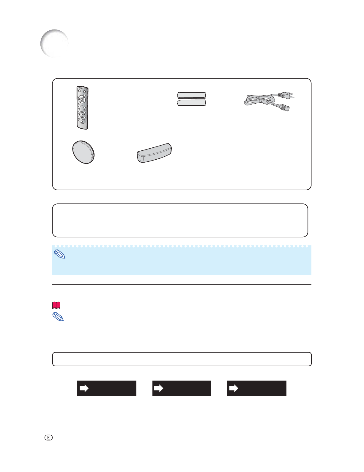
Supplied accessories
Remote control
• RRMCGA500WJSA
for XV-Z20000
• RRMCGA500WJSB
for DT-5000
Lens cap (attached)
PCAPH1056CESA
Optional accessories
■ Lamp unit AN-K20LP
■ 3 RCA to 15-pin D-sub cable (9'10" (3.0 m)) AN-C3CP2
■ DVI to 15-pin D-sub adaptor (7.9" (20 cm)) AN-A1DV
■ DVI cable (9'10" (3.0 m)) AN-C3DV
Two AA size batteries
Terminal cover
• GCOVAB677WJKA
for XV-Z20000
• GCOVAB677WJKB
for DT-5000
Power cord
(6' (1.8 m))
QACCDA007WJPZ
Operation manual
Note
• Some of the optional accessories may not be available depending on the region. Please check with your
nearest Sharp Authorized Service Center or Dealer.
Marks Used in This Operation Manual
............ Indicates safeguards when using the projector.
Info
............ Indicates additional information for setting up and operating the projector.
Note
• In this operation manual, the illustration and the screen display are simplifi ed for explanation, and may differ
slightly from actual display.
For Future Reference
IndexMaintenance Troubleshooting
P. 46 and 47 P. 61 and 62
P. 65
-4
Page 6
IMPORTANT SAFEGUARDS
CAUTION: Please read all of these instructions before you operate this product and save these
instructions for later use.
Electrical energy can perform many useful functions. This product has been engineered and manufactured to assure your personal safety. BUT IMPROPER USE CAN RESULT IN POTENTIAL ELECTRICAL SHOCK OR FIRE
HAZARDS. In order not to defeat the safeguards incorporated in this product, observe the following basic rules for
its installation, use and servicing.
1. Read Instructions
All the safety and operating instructions should be read before
the product is operated.
2. Retain Instructions
The safety and operating instructions should be retained for
future reference.
3. Heed Warnings
All warnings on the product and in the operating instructions
should be adhered to.
4. Follow Instructions
All operating and use instructions should be followed.
5. Cleaning
Unplug this product from the wall outlet before cleaning. Do
not use liquid cleaners or aerosol cleaners. Use a damp cloth
for cleaning.
6. Attachments
Do not use attachments not recommended by the product
manufacturer as they may cause hazards.
7. Water and Moisture
Do not use this product near water–for example, near a bath
tub, wash bowl, kitchen sink, or laundry tub; in a wet basement;
or near a swimming pool; and the like.
8. Accessories
Do not place this product on an unstable cart, stand, tripod,
bracket, or table. The product may fall, causing serious injury
to a child or adult, and serious damage to the product. Use
only with a cart, stand, tripod, bracket, or table recommended
by the manufacturer, or sold with the product. Any mounting
of the product should follow the manufacturer’s instructions,
and should use a mounting accessory recom mended by the
manufacturer.
9. Transportation
A product and cart combination should
be moved with care. Quick stops, excessive force, and uneven surfaces may
cause the product and cart combination
to overturn.
10. Ventilation
Slots and openings in the cabinet are provided for ventilation
to ensure reliable operation of the product and to protect it
from overheating, and these openings must not be blocked
or covered. The open ings should never be blocked by placing
the product on a bed, sofa, rug, or other similar surface. This
prod uct should not be placed in a built-in installation such as
a book case or rack unless proper ventilation is provided or the
manufacturer’s in structions have been adhered to.
11. Power Sources
This product should be operated only from the type of power
source indicated on the marking label. If you are not sure of
the type of power supply to your home, consult your product
dealer or local power com pany. For products intended to
operate from battery power, or other sources, refer to the
operating instructions.
12. Grounding or Polarization
This product is provided with one of the following types of plugs.
If the plug should fail to fi t into the power outlet,
please contact your electrician.
Do not defeat the safety purpose of the plug.
a. Two-wire type (mains) plug.
b. Three-wire grounding type (mains) plug with a
grounding terminal.
This plug will only fi t into a grounding type power
outlet.
13. Power-Cord Protection
Power-supply cords should be routed so that they are not likely
to be walked on or pinched by items placed upon or against
them, paying particular attention to cords at plugs, convenience
receptacles, and the point where they exit from the product.
14. Lightning
For added protection for this product during a lightning storm, or
when it is left unattended and unused for long periods of time,
unplug it from the wall outlet and disconnect the cable system.
This will pre vent damage to the product due to lightning and
power-line surges.
15. Overloading
Do not overload wall outlets, extension cords, or integral
convenience receptacles as this can result in a risk of fi re or
electric shock.
16. Object and Liquid Entry
Never push objects of any kind into this product through
openings as they may touch dangerous voltage points or
short-out parts that could result in a fi re or electric shock. Never
spill liquid of any kind on the product.
17. Servicing
Do not attempt to service this product yourself as opening or
removing covers may expose you to dan ger ous voltage or other
hazards. Refer all servicing to qualifi ed service personnel.
18. Damage Requiring Service
Unplug this product from the wall outlet and refer servicing to
qualifi ed service person nel under the following conditions:
a. When the power-supply cord or plug is damaged.
b. If liquid has been spilled, or objects have fallen into the
product.
c. If the product has been exposed to rain or water.
d. If the product does not operate normally by following the
operating instructions. Adjust only those con trols that are
covered by the operating instructions, as an improper
adjustment of other controls may result in damage and
will often require extensive work by a qualifi ed technician
to restore the product to normal operation.
e. If the product has been dropped or damaged in any
way.
f. When the product exhibits a distinct change in
performance, this indicates a need for service.
19. Replacement Parts
When replacement parts are required, ensure the service
technician has used replace ment parts specified by the
manufacturer or have the same characteristics as the original
part. Unauthorized substitutions may result in fi re, electric shock,
or other hazards.
20. Safety Check
Upon completion of any service or repairs to this product, ask
the service technician to per form safety checks to determine
that the product is in proper operating condition.
21.Wall or Ceiling Mounting
This product should be mounted to a wall or ceiling only as
recommended by the manu facturer.
22. Heat
This product should be situated away from heat sources such
as radiators, heat registers, stoves, or other products (including
amplifi ers) that produce heat.
Introduction
-5
Page 7
Observe the following safeguards when setting up your projector.
Caution concerning the lamp unit
■ Potential hazard of glass particles if lamp ruptures.
In case of lamp rupture, contact your nearest Sharp
Authorized Service Center or Dealer for replacement.
See “Regarding the Lamp” on page 48.
Caution concerning the setup of the projector
■ For minimal servicing and to maintain high image quality,
SHARP recommends that this projector be installed in
an area free from humidity, dust and cigarette smoke.
When the projector is subjected to these environments,
the vents and lens must be cleaned more often. As
long as the projector is regularly cleaned, use in these
environments will not reduce the overall operation life of
the unit. Internal cleaning should only be performed by
a Sharp Authorized Service Center or Dealer.
Do not set up the projector in places exposed to
direct sunlight or bright light.
■ Position the screen so that it is not in direct sunlight or
room light. Light falling directly on the screen washes out
the colors, making viewing diffi cult. Close the curtains
and dim the lights when setting up the screen in a sunny
or bright room.
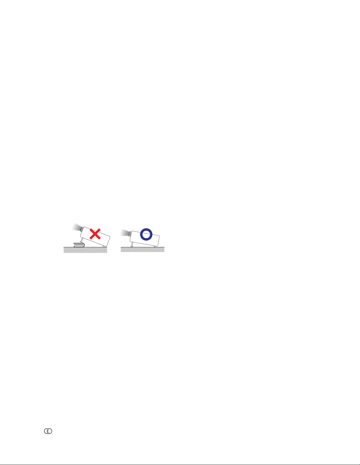
Caution regarding placing of the projector
■ Place the projector on a level site within the adjustment
range (±5 degrees) of the adjustment foot.
Rest your eyes occasionally.
■ Continuously watching the screen for long hours will
cause eye strain. Be sure to occasionally rest your
eyes.
Avoid locations with extremes of temperature.
■ The operating temperature of the projector is from 41°F
to 95°F (+5°C to +35°C).
■ The storage temperature of the projector is from –4°F
to 140°F (–20°C to +60°C).
Do not block the exhaust and intake vents.
■ Allow at least 1113/16 inches (30 cm) of space between
the exhaust vent and the nearest wall or obstruction.
■ Be sure that the intake vent and the exhaust vent are not
obstructed.
■ If the cooling fan becomes obstructed, a protection
circuit will automatically put the projector into standby
mode to prevent overheat damage. This does not indicate a malfunction. (See page 46.) Remove the projector
power cord from the wall outlet and wait at least 10 minutes. Place the projector where the intake and exhaust
vents are not blocked, plug the power cord back in and
turn on the projector. This will return the projector to the
normal operating condition.
■ When turning off the projector, the cooling fan runs to
decrease the internal temperature for a while. Unplug
the power cord after the cooling fan stops. The period
the cooling fan runs will vary, depending on the circumstances and the internal temperature.
■ After the projector is purchased, a faint smell from the
vent may appear when the power is fi rst turned on. This
is normal and is not a malfunction. It will disappear after
the projector is used for a while.
When using the projector in high-altitude areas
such as mountains (at altitudes of approximately 4,900 feet (1,500 meters) or more)
■ When you use the projector in high-altitude areas with
thin air, set “Fan Mode” to “High”. Neglecting this can
affect the longevity of the optical system.
Warning about placing the projector in a high
position
■ When placing the projector in a high position, ensure that
it is secured carefully to avoid personal injury caused by
the projector falling down.
Do not subject the projector to hard impact
and/or vibration.
■ Protect the lens so as not to hit or damage the surface
of the lens.
Caution regarding usage of the projector
■ When using the projector, be sure not to subject it to
hard impact and/or vibration, as this can result in damage. Take extra care with the lens. Before moving the
projector, be sure to unplug the power cord from the wall
outlet, and disconnect any other cables connected to
it.
■ Do not carry the projector by holding the lens.
■ When storing the projector, re-attach the lens cap. (See
page 8.)
■ Do not expose the projector to direct sunlight or place
next to heat sources. Doing so may affect the cabinet
color or cause deformation of the plastic cover.
Other connected equipment
■ When connecting a computer or other audio-visual
equipment to the projector, make the connections AFTER
unplugging the power cord of the projector from the AC
outlet and turning off the equipment.
■ Please read the operation manuals of the projector and
the equipment to be connected for instructions on how
to make the connections.
Using the projector in other countries
■ The power supply voltage and the shape of the plug may
vary depending on the region or country you are using
the projector in. When using the projector overseas, be
sure to use an appropriate power cord for the country
you are in.
-6
Page 8
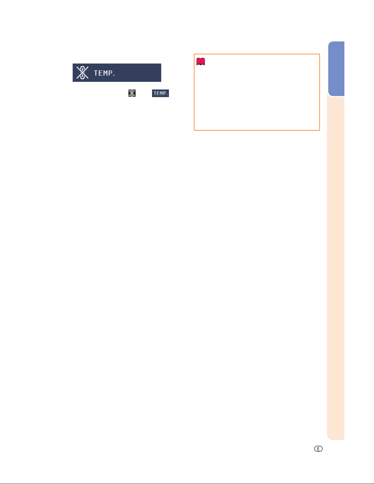
Temperature monitor function
■ If the projector starts to overheat due to setup problems
or blockage of the air vents, “ ” and “ ” will
illuminate in the lower left corner of the picture. If the
temperature continues to rise, the lamp will turn off, the
temperature warning indicator on the projector will blink,
and after a 90-second cooling-off period the projector
will enter standby mode. Refer to “Maintenance Indicators/Maintenance” on page 46 for details.
Introduction
Info
• The cooling fan regulates the internal temperature, and its performance is automatically controlled. The sound of the fan may change during
projector operation due to changes in the fan
speed. This does not indicate malfunction.
• Do not unplug the power cord during projection
or cooling fan operation. This can cause damage
due to rise in internal temperature, as the cooling
fan also stops.
-7
Page 9
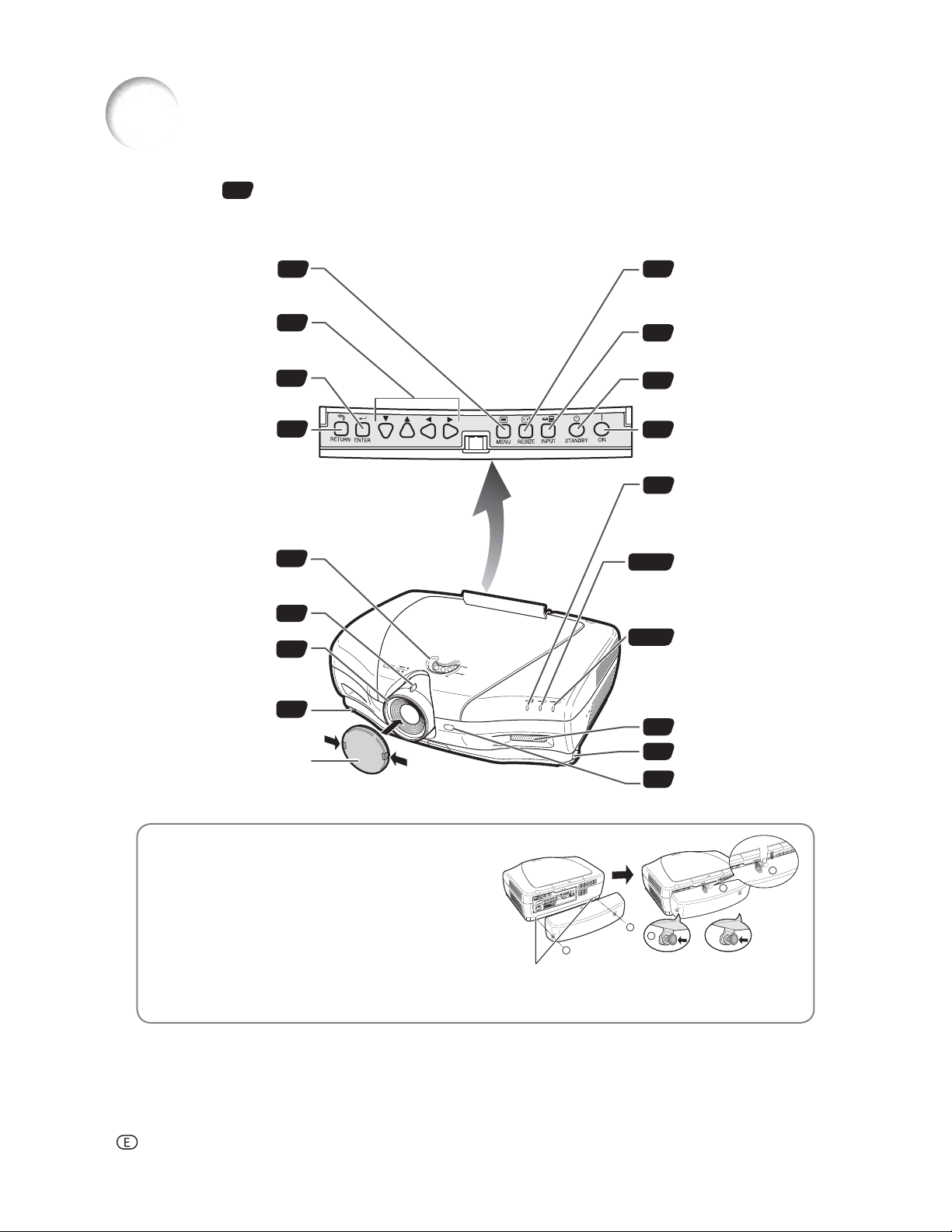
Part Names and Functions
Numbers in refer to the main pages in this operation manual where the topic is explained.
Projector
For displaying adjustment
MENU button
and setting screens.
Adjustment buttons
(, ,,)
For selecting menu items.
ENTER button
For setting items selected
or adjusted on the menu.
RETURN button
For undoing an operation.
Lens shift dial
For moving the projected
image vertically.
Zoom knob
Focus ring
Adjustment foot
Lens cap
Pressing the two tabs, you can
remove/attach the lens cap.
34
34
34
34
28
27
27
28
RESIZE button
30
For switching the screen
size (SIDE BAR, SMART
STRETCH, etc.).
INPUT button
27
For displaying the Input
list.
STANDBY button
26
For putting the projector
into the standby mode.
ON button
25
For turning the power on.
Temperature warning
46
indicator
When the internal
temperature rises, this
indicator will illuminate red.
Lamp indicator
25, 46
Illuminates blue, indicating
normal function. Replace
the lamp when the
indicator illuminates red.
Power indicator
25, 46
Illuminates red, when the
projector is in standby.
When the power is turned
on, this indicator will
illuminate blue.
Intake vent
47
Adjustment foot
28
Remote control sensor
11
Using the Terminal Cover
When the projector is used on a desktop, high mounted
or ceiling mounted, attach the terminal cover (supplied) to
hide the connecting cables.
Attaching the Terminal Cover
Align the hook on the terminal cover with the insert
hole in the hook at the back of the projector.
Press the hook in the direction indicated with the ar row
to fasten the ter minal cover to the projector.
Insert the terminal cover into the mounting groove on
the projector while pushing the tabs inside the terminal
cover to the out side with your fi ngers.
-8
PUSH!
3
3
1
1
2
Remove the rubber cap attached on the projector and at tach the hooks.
Page 10
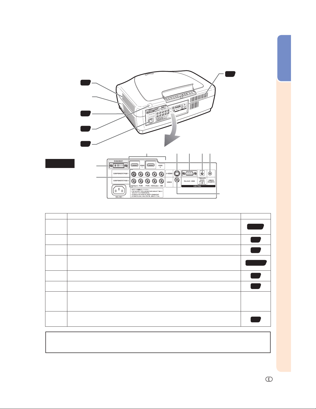
Projector (Rear View)
Intake vent
Kensington Security
Standard connector
47
47
Introduction
Intake vent
Exhaust vent
Remote control
sensor
AC socket
Connect the supplied power cord.
47
11
25
Terminals
Terminal Description Page
COMPONENT/RGB1, 2 terminals
Connecting video equipment with component output terminal (DVD player, etc.) or a computer with analog RGB output terminal.
S-VIDEO terminal
Connecting video equipment with S-video output terminal (DVD player, VCR, etc.).
VIDEO terminal
Connecting video equipment without S-video output terminal.
DVI terminal
Connecting video equipment with DVI output terminal (DVD player, DTV decoder, computer,
etc.).
HDMI1, 2 terminals
Connecting video equipment with HDMI output terminal.
RS-232C terminal
Connecting a computer to control the projector.
TRIGGER terminal
When the projector is turned on, a control signal (DC 12V) outputs from this terminal. If an
electric screen or other compatible device is connected, it can be turned on when the projector
is turned on.
WIRED REMOTE control input terminal
Connecting the remote control via a cable when the projector is placed out of the reach of
remote control signals.
20, 21
22
22
18-20, 23
18
24
—
10
Using the Kensington Lock
• This projector has a Kensington Security Standard connector for use with a Kensington MicroSaver Security System.
Refer to the information that came with the system for instructions on how to use it to secure the projector.
-9
Page 11
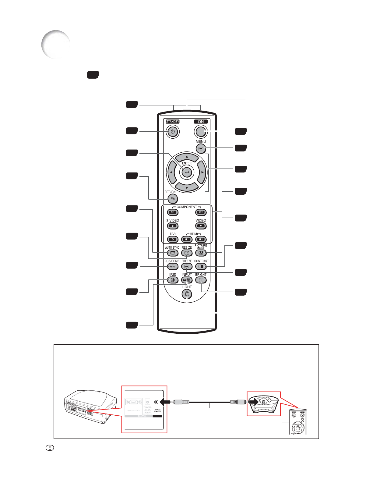
Part Names and Functions (Continued)
Numbers in refer to the main pages in this operation manual where the topic is explained.
Remote Control
Remote control signal
transmitters
11
WIRED R/C JACK
For controlling the projector by
connecting the remote control to
the projector.
For putting the projector into the
STANDBY button
standby mode.
ENTER button
For setting items selected or
adjusted on the menu.
RETURN button
For undoing an operation.
AUTO SYNC button
For automatically adjusting images
when connected to a computer.
RESIZE button
For switching the screen size
(SIDE BAR, SMART STRETCH,
etc.).
RGB/COMP. button
For switching to the respective
input signal type.
IRIS button
For switching “HIGH
BRIGHTNESS MODE”, “MEDIUM
MODE” and “HIGH CONTRAST
MODE”.
INPUT button
For displaying the Input list.
26
34
34
41
30
44
29
27
ON button
25
For turning the power on.
MENU button
34
For displaying adjustment and
setting screens.
Adjustment buttons
34
(, ,,)
For selecting menu items.
Input Mode Select buttons
27
For switching to the respective
input modes.
PICTURE MODE button
29
For selecting the appropriate
picture to best match the projected
image.
CONTRAST button
29
For displaying the contrast
adjustment screen.
FREEZE button
29
For freezing images.
BRIGHT button
29
For displaying the brightness
adjustment screen.
LIGHT button
For lighting all buttons on the
remote control.
Connecting the Remote Control to the Projector
When the remote control cannot be used due to the range or positioning of the projector, connect a ø3.5 mm
minijack cable (commercially available) from the WIRED R/C JACK on the top of the remote control to the WIRED
REMOTE control input terminal on the rear of the projector.
To WIRED REMOTE control input terminal
ø3.5 mm minijack cable
(commercially available)
-10
To WIRED R/C JACK
Remote control
Page 12
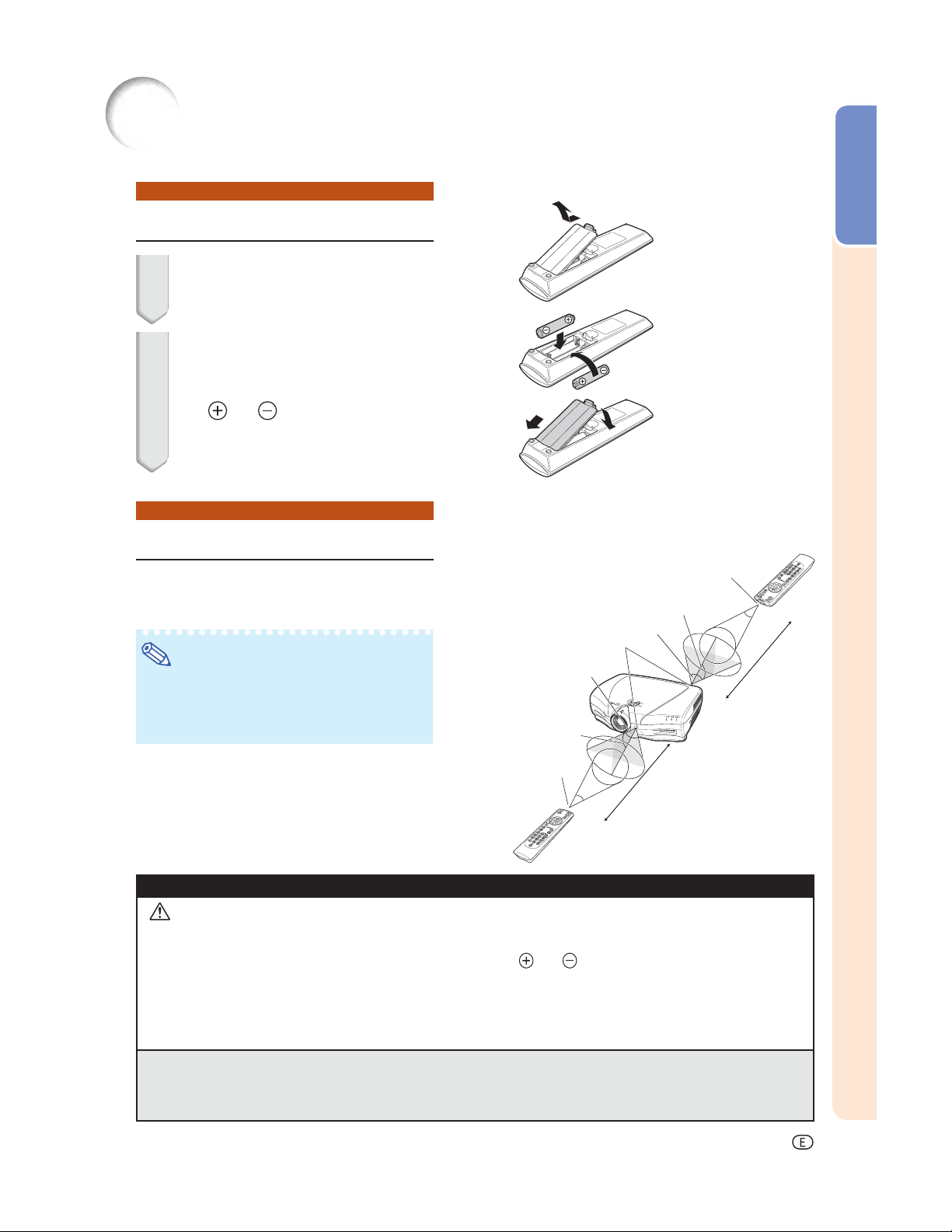
Using the Remote Control
Inserting the Batteries
1 Pull down the tab on the cover
and remove the cover towards
the direction of the arrow.
2 Insert the supplied batteries and
put back the cover.
• Make sure the polarities correctly match
the
and marks inside the battery
compartment.
• When putting back the cover, be sure that
the cover clicks in place and settles.
Usable Range
Introduction
The remote control can be used to control
the projector within the ranges shown in the
illustration.
Remote control sensors
Note
• The signal from the remote control can be
refl ected off a screen for easy operation. However, the effective distance of the signal may
differ depending on the screen material.
When using the remote control:
• Be sure not to drop, expose to moisture or high
temperature.
• The remote control may malfunction under a
fl uorescent lamp. In this case, move the projector away from the fl uorescent lamp.
Incorrect use of the batteries may cause them to leak or explode. Please follow the precautions below.
Remote control
signal transmitters
30°
30°
30°
Remote control
Remote control
signal transmitters
30°
30°
23' (7 m)
30°
23' (7 m)
Caution
• Danger of explosion if bettery is incorrectly replaced.
Replace only with the same or equivalent type.
• Insert the batteries making sure the polarities correctly match the
• Batteries of different types have different properties, therefore do not mix batteries of different types.
• Do not mix new and old batteries.
This may shorten the life of new batteries or may cause old batteries to leak.
Remove the batteries from the remote control once they have run out, as leaving them in can cause them to leak.
•
Battery fl uid from leaked batteries is harmful to skin, therefore be sure to fi rst wipe them and then remove them using a cloth.
• The batteries included with this projector may run down in a short period, depending on how they are kept.
Be sure to replace them as soon as possible with new batteries.
• Remove the batteries from the remote control if you are not to use the remote control for a long time.
• Comply with the rules (ordinance) of each local government when disposing of worn-out batteries.
and marks inside the battery compartment.
-11
Page 13
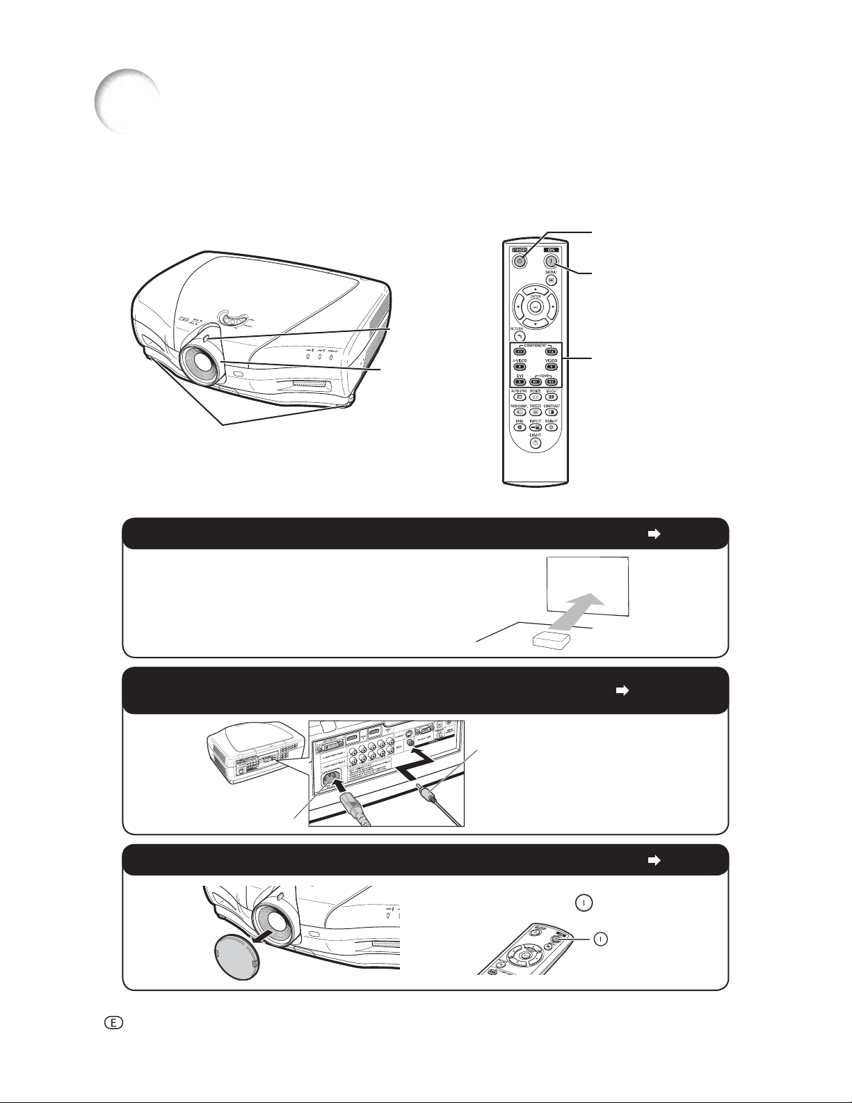
Quick Start
This section provides an example showing how to connect the projector to video equipment with a brief explanation of the steps from connection through to image projection.
For details, see the pages suggested in each step.
7 STANDBY button
3 ON button
6 Zoom knob
6 Focus ring
6 Adjustment feet
1. Place the projector facing a screen
2.
Connect the projector to the video equipment and plug
the power cord into the AC socket of the projector
To VIDEO terminal
5 Input Mode
Select buttons
Page 14
Pages 18-25
Connect the audio output terminal
of the video equipment to the audio
input terminal of the audio equipment
AC socket
using an audio cable.
3. Remove the lens cap and turn the projector on
Pointing the remote control towards the
projector, press the
-12
Page 25
ON button.
ON
Page 14
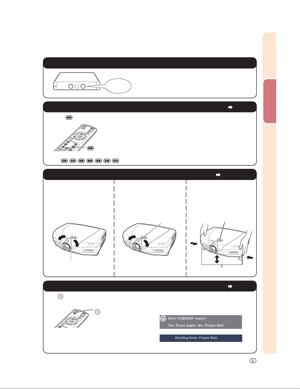
4. Turn the video equipment on and start playback
Playback
5. Select the input mode
Press the VIDEO button on the remote control to select “VIDEO” for the Input mode.
VIDEO
• Press
/ / / / / / on the remote control to switch the Input mode.
6. Adjust the projector angle, focus and zoom
1. The focus is adjusted by
rotating the focus ring.
2. Zooming is adjusted by
moving the zoom knob.
Zoom knob
3. The projector angle is
adjusted by using the
adjustment feet. As for
adjustment of the vertical
position of the projected
image, use the lens shift dial.
Quick Start
Page 27
Pages 27, 28
Lens shift dial
Focus ring
Foot releases
7. Turn the power off
Press STANDBY on the remote control, then press that button again while the confi rmation message
is displayed, to put the projector into standby mode.
STANDBY
• Unplug the power cord from the AC outlet after the cooling fan stops.
On-screen display
Page 26
-13
Page 15
Setting Up the Projector
Setting Up the Projector
For optimal image quality, position the projector perpendicular to the screen with the projector’s feet fl at and
level.
Note
• The projector lens should be centered in the middle of the screen. If the horizontal line passing through
the lens center is not perpendicular to the screen, the image will be distorted, making viewing diffi cult.
• For optimal image, position the screen so that it is not in direct sunlight or room light. Light falling directly
on the screen washes out the colors, making viewing diffi cult. Close the curtains and dim the lights when
setting up the screen in a sunny or bright room.
• A polarizing screen cannot be used with this projector.
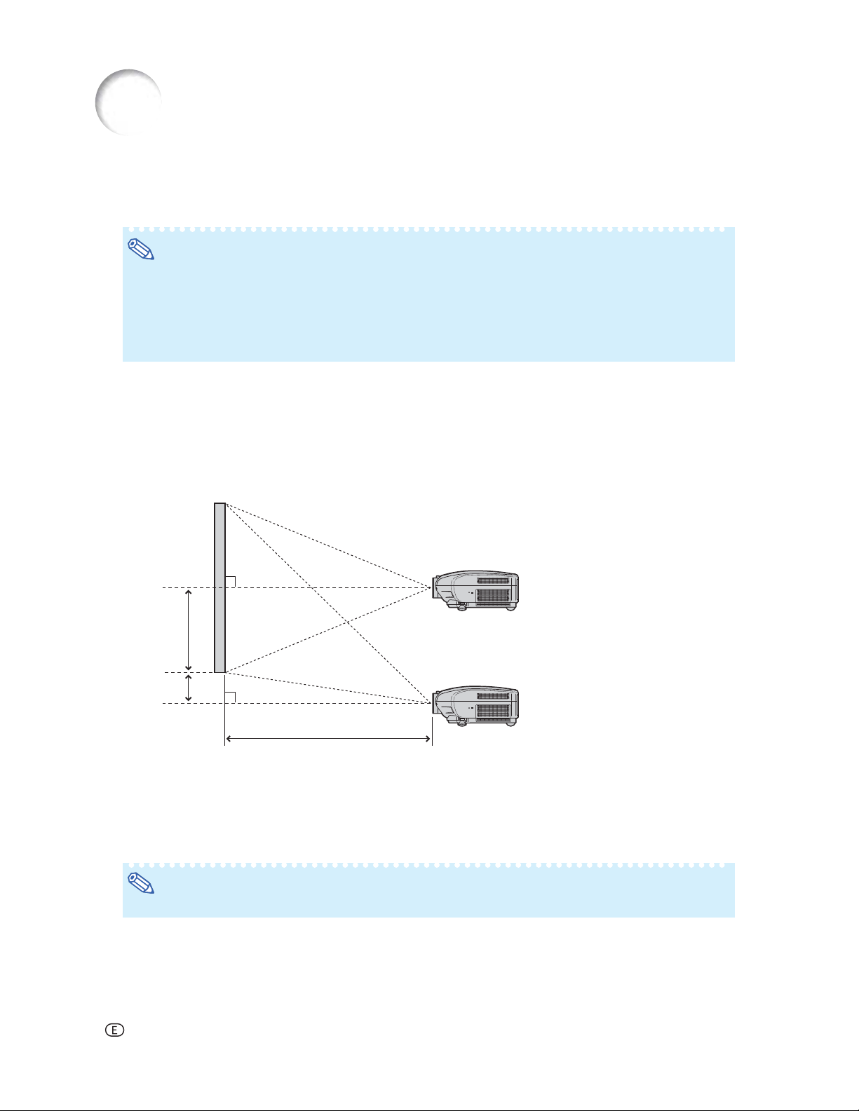
Standard Setup (Front Projection)
■ Place the projector at the required distance from the screen according to the desired picture size.
Example of standard setup
Image
Lens shifted to lowest position
90°
Lens center
H1
H2
L : Projection distance
H1: Distance from the lens center to the bottom of the image
(when the lens is shifted to the lowest position)
H2: Distance from the lens center to the bottom of the image
(when the lens is shifted to the highest position)
Note
• For details, refer to “Picture (Screen) Size and Projection Distance” on page 16.
90°
Lens center
L
Lens shifted to highest position
-14
Page 16
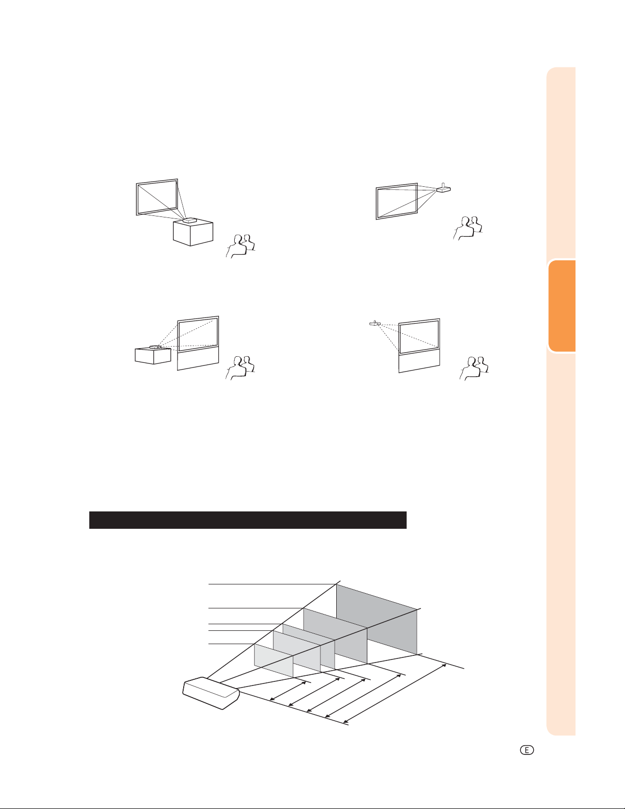
Projection (PRJ) Mode
The projector can use any of the 4 projection modes, shown in the diagram below. Select the mode most appropriate for the projection setting in use. (You can set the PRJ Mode in “Options” menu. See page 45.)
■ Table mounted, front projection
Menu item ➞ “Front”
■ Table mounted, rear projection
(with a translucent screen)
Menu item ➞ “Rear”
■ Ceiling mounted, front projection
Menu item ➞ “Ceiling + Front”
■ Ceiling mounted, rear projection
(with a translucent screen)
Menu item ➞ “Ceiling + Rear”
Ceiling-mount Setup
■ It is recommended that you use the optional Sharp ceiling-mount bracket for this installation. Before mounting
the projector, contact your nearest Sharp Authorized Service Center or Dealer to obtain the recommended
ceiling-mount bracket (sold separately).
• AN-CM250 ceiling-mount bracket (for U.S.A.).
• AN-NV6T ceiling-mount bracket, its AN-TK201 and AN-TK202 extension tubes (for countries other than
the U.S.A.).
■ Invert the image by setting “Ceiling + Front” in “PRJ Mode”. See page 45 for use of this function.
Setup
Indication of the Projection Image Size and Projection Distance
For details, refer to “Picture (Screen) Size and Projection Distance” on page 16.
Example : When using a wide screen (16:9)
Picture Size
300"
200"
100"
80"
60"
52.3
29.4
69.7
"
×
"
8'0" ~ 10'10"
174.3
87.2
"
×49
"
"
×39.2
"
(2.4 m ~ 3.3 m)
10'9" ~ 14'6"
(3.3 m ~ 4.4 m)
261.5
"
×
98.1
"
13'5" ~ 18'2"
27'1" ~ 36'6"
(4.1 m ~ 5.5 m)
"
×147.1
"
40'9" ~ 54'10"
(8.3 m ~ 11.1 m)
(12.4 m ~ 16.7 m)
Projection
Distance
-15
Page 17
Setting Up the Projector (Continued)
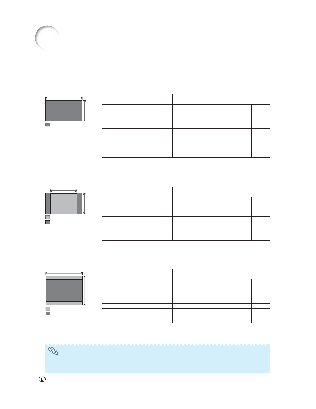
Picture (Screen) Size and Projection Distance
The projection screen size varies according to the distance from the lens of the projector to the screen. Install
the projector so that projected images are projected onto the screen at the optimum size by referring to the
table below. Use the values in the table as a reference when installing the projector.
When using a wide screen (16:9): In case of displaying the 16:9 picture on the whole of the 16:9 screen.
16
Diag. (x) Width Height Maximum [L1] Minimum [L2] Lower [H1] Upper [H2]
9
: Projected image
x : Picture size (diag.) (inches)
L1 : Maximum Projection distance (ft/m)
L2 : Minimum Projection distance (ft/m)
Picture (Screen) size Projection distance [L]
300" 261.5" (6.6 m) 147.1" (3.7 m) 54'10" (16.7 m) 40'9" (12.4 m) –147" (–374 cm) 0" (0 cm)
250" 217.9" (5.5 m) 122.6" (3.1 m) 45'8" (13.9 m) 33'11" (10.3 m) –122" (–311 cm) 0" (0 cm)
200" 174.3" (4.4 m) 98.1" (2.5 m) 36'6" (11.1 m) 27'1" (8.3 m) –98" (–249 cm) 0" (0 cm)
150" 130.7" (3.3 m) 73.5" (1.9 m) 27'4" (8.3 m) 20'3" (6.2 m) –73" (–187 cm) 0" (0 cm)
120" 104.6" (2.7 m) 58.8" (1.5 m) 21'10" (6.7 m) 16'2" (4.9 m) –58" (–149 cm) 0" (0 cm)
110" 95.9" (2.4 m) 53.9" (1.4 m) 20'0" (6.1 m) 14'10" (4.5 m) –53" (–137 cm) 0" (0 cm)
100" 87.2" (2.2 m) 49" (1.2 m) 18'2" (5.5 m) 13'5" (4.1 m) –49" (–125 cm) 0" (0 cm)
80" 69.7" (1.8 m) 39.2" (1.0 m) 14'6" (4.4 m) 10'9" (3.3 m) –39" (–100 cm) 0" (0 cm)
60" 52.3" (1.3 m) 29.4" (0.7 m) 10'10" (3.3 m) 8'0" (2.4 m) –29" (–75 cm) 0" (0 cm)
40" 34.9" (0.9 m) 19.6" (0.5 m) 7'2" (2.2 m) 5'3" (1.6 m) –19" (–50 cm) 0" (0 cm)
The formula for picture size and projection distance
L1 = (0.05593x – 0.05550)/0.3048 (ft)
L2 = (0.04158x – 0.05665)/0.3048 (ft)
When using a normal screen (4:3) and projecting 4:3 image (SIDE BAR Mode)
4
3
: Screen
: Projected image
x
: Picture size (diag.) (inches)
Diag. (x) Width Height Maximum [L1] Minimum [L2] Lower [H1] Upper [H2]
L1 : Maximum Projection distance (ft/m)
L2 : Minimum Projection distance (ft/m)
Picture (Screen) size Projection distance [L]
250" 200" (5.1 m) 150" (3.8 m) 56'0" (17.1 m) 41'7" (12.7 m) –150" (–381 cm) 0" (0 cm)
200" 160" (4.1 m) 120" (3.0 m) 44'9" (13.6 m) 33'2" (10.1 m) –120" (–305 cm) 0" (0 cm)
150" 120" (3.0 m) 90" (2.3 m) 33'6" (10.2 m) 24'10" (7.6 m) –90" (–229 cm) 0" (0 cm)
120" 96" (2.4 m) 72" (1.8 m) 26'9" (8.2 m) 19'10" (6.1 m) –72" (–183 cm) 0" (0 cm)
110" 88" (2.2 m) 66" (1.7 m) 24'6" (7.5 m) 18'2" (5.5 m) –66" (–168 cm) 0" (0 cm)
100" 80" (2.0 m) 60" (1.5 m) 22'3" (6.8 m) 16'6" (5.0 m) –60" (–152 cm) 0" (0 cm)
80" 64" (1.6 m) 48" (1.2 m) 17'9" (5.4 m) 13'2" (4.0 m) –48" (–122 cm) 0" (0 cm)
60" 48" (1.2 m) 36" (0.9 m) 13'4" (4.1 m) 9'10" (3.0 m) –36" (–91 cm) 0" (0 cm)
The formula for picture size and projection distance
L1 = (0.06845x – 0.05550)/0.3048 (ft)
L2 = (0.05089x – 0.05665)/0.3048 (ft)
H1 = –1.2453x/2.54 (in)
H2 = 0
H1 = –1.524x/2.54 (in)
H2 = 0
Distance from the lens center
to the bottom of the image [H]
Distance from the lens center
to the bottom of the image [H]
When using a normal screen (4:3): In case of setting the 16:9 picture to the full horizontal width of the 4:3 screen.
4
Diag. (x) Width Height Maximum [L1] Minimum [L2] Lower [H1] Upper [H2]
3
: Screen
: Projected image
x
: Picture size (diag.) (inches)
250" 200" (5.1 m) 150" (3.8 m) 41'11" (12.8 m) 31'1" (9.5 m) –112" (–286 cm) 0" (0 cm)
200" 160" (4.1 m) 120" (3.0 m) 33'6" (10.2 m) 24'10" (7.6 m) –90" (–229 cm) 0" (0 cm)
150" 120" (3.0 m) 90" (2.3 m) 25'1" (7.6 m) 18'7" (5.7 m) –67" (–171 cm) 0" (0 cm)
120" 96" (2.4 m) 72" (1.8 m) 20'0" (6.1 m) 14'10" (4.5 m) –54" (–137cm) 0" (0 cm)
110" 88" (2.2 m) 66" (1.7 m) 18'4" (5.6 m) 13'7" (4.1 m) –49" (–126 cm) 0" (0 cm)
100" 80" (2.0 m) 60" (1.5 m) 16'8" (5.1 m) 12'4" (3.8 m) –45" (–114 cm) 0" (0 cm)
80" 64" (1.6 m) 48" (1.2 m) 13'3" (4.1 m) 9'10" (3.0 m) –36" (–91 cm) 0" (0 cm)
60" 48" (1.2 m) 36" (0.9 m) 9'11" (3.0 m) 7'4" (2.2 m) –27" (–69 cm) 0" (0 cm)
L1 : Maximum Projection distance (ft/m)
L2 : Minimum Projection distance (ft/m)
Picture (Screen) size Projection distance [L]
The formula for picture size and projection distance
L1 = (0.05133x – 0.05550)/0.3048 (ft)
L2 = (0.03817x – 0.05665)/0.3048 (ft)
H1 = –1.143x/2.54 (in)
H2 = 0
Distance from the lens center
to the bottom of the image [H]
Note
• Allow a margin of error in the value in the diagrams above.
• When the distance from the lens center to the bottom of the image (H) is a negative number, this indicates
that the bottom of the image is below the lens center.
-16
Page 18
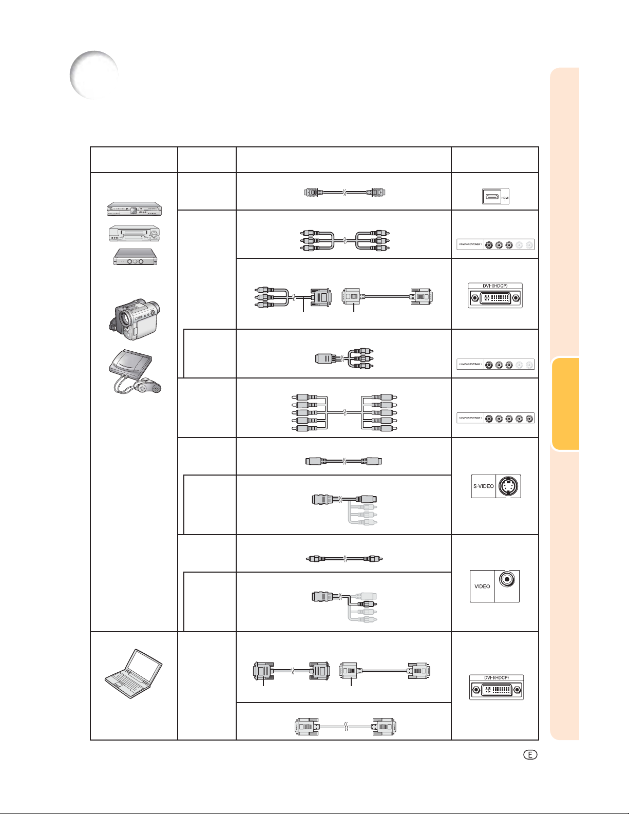
Samples of Cables for Connection
• For more details of connection and cables, refer to the operation manual of the connecting equipment.
• You may need other cables or connectors not listed below.
Equipment Input signal Cable
Audio-visual
equipment
Camera/video game
HDMI video HDMI cable (commercially available) HDMI1, 2
Component
video
Terminal for
using the
dedicated
cable
RGB video 5 RCA RGB cable (commercially available) COMPONENT/
S-video S-video cable (commercially available) S-VIDEO
Component cable (commercially available) COMPONENT/
3 RCA to 15-pin D-sub cable (sold separately: AN-C3CP2)
DVI to 15-pin D-sub adaptor (sold separately: AN-A1DV)
3 RCA to 15-pin D-sub cable DVI to 15-pin D-sub adaptor
Dedicated cable attached to the connected equipment COMPONENT/
Terminal on the
projector
RGB1, 2
DVI
RGB1, 2
Connections
RGB1, 2
Terminal for
using the
dedicated
cable
Video Video cable (commercially available) VIDEO
Terminal for
using the
dedicated
cable
Computer RGB video RGB cable (commercially available)
Dedicated cable attached to the connected equipment
Dedicated cable attached to the connected equipment
DVI to 15-pin D-sub adaptor (sold separately: AN-A1DV)
RGB cable DVI to 15-pin D-sub adaptor
DVI cable (sold separately: AN-C3DV)
DVI
-17
Page 19
Connecting to Video Equipment
Before connecting, be sure to unplug the power cord of the projector from the AC outlet and turn off the devices
to be connected. After making all connections, turn on the projector and then the other devices.
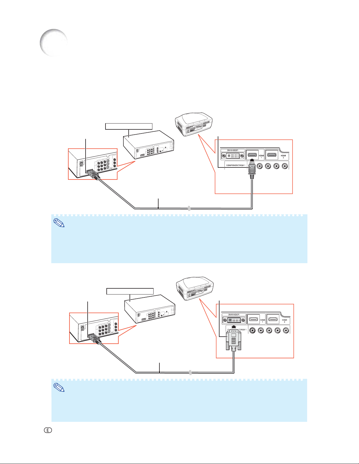
Connecting Equipment with HDMI Output Terminal to the HDMI Terminal on the Projector
HDMI is a new specialized interface capable of delivering a video and audio signal to the terminal using just one cable.
Since this projector does not support an audio signal by itself, use an amplifi er or other audio device.
For video connection, use a cable that conforms to HDMI standards. Using cables that do not conform to HDMI
standards may result in a malfunction.
HDMI-compatible device
To HDMI output terminal
HDMI cable (type A)
(commercially available)
To HDMI1 or 2 terminal
Note
• HDMI (High-Defi nition Multimedia Interface) is a digital AV interface that can deliver a high-defi nition video
signal, multi-channel audio signal, and bi-directional control signal all in just one cable.
• Because it is compatible with the HDCP (High-bandwidth Digital Content Protection) system, the digital
video signal does not degrade when transmitted, and a high-quality image with a simple connection can
be enjoyed.
Connecting Equipment with the HDMI Output Terminal to the DVI Terminal on the Projector
HDMI-compatible device
To HDMI output terminal
DVI to HDMI cable
(commercially available)
To DVI terminal
Note
• When connecting the projector to the video equipment in this way, select “Signal Type” in the “Options”
menu. See page 44.
• When a DVI to HDMI conversion cable is connected to the HDMI terminal, a proper picture may not be
displayable.
-18
Page 20
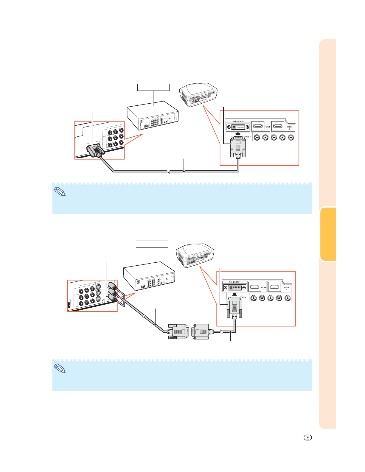
Connecting Video Equipment with the DVI Output Terminal to the DVI Terminal on the Projector
DVD Player,etc.
To DVI Digital output terminal
DVI cable
(sold separately: AN-C3DV)
To DVI terminal
Note
• When connecting the projector to the video equipment in this way, select “Signal Type” in the “Options”
menu. See page 44.
Connecting Component Video Equipment to the DVI Terminal on the Projector
DVD Player,etc.
To component output terminal
To DVI terminal
Connections
3 RCA to 15-pin D-sub cable
(sold separately: AN-C3CP2)
DVI to 15-pin D-sub adaptor
(sold separately: AN-A1DV)
Note
• When connecting the projector to the video equipment in this way, select “Signal Type” in the “Options”
menu. See page 44.
-19
Page 21
Connecting to Video Equipment (Continued)
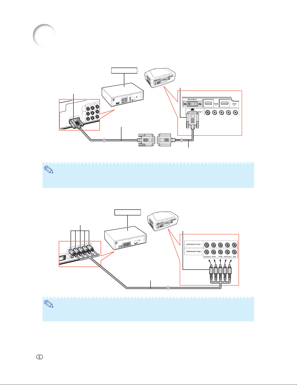
Connecting RGB Equipment to the DVI Terminal on the Projector
DVD Player,etc.
To DVI terminal
To RGB output terminal
RGB cable
(commercially available)
DVI to 15-pin D-sub adaptor
(sold separately: AN-A1DV)
Note
• When connecting the projector to the video equipment in this way, select “A. RGB” for “Signal Type” in
the “Options” menu. See page 44.
Connecting RGB Equipment to the COMPONENT/RGB Terminals on the Projector
DVD Player,etc.
To analog RGB
output terminal
To COMPONENT/RGB 1 or 2 terminals
5 RCA RGB cable
(commercially available)
Note
• The (HD/C sync) and (VD) terminals may be used depending on the specifi cations of the RGB equipment
connected to this projector. Please refer to the operation manual of the RGB equipment for details.
-20
Page 22

Connecting Component Video Equipment to the COMPONENT/RGB Terminals on the Projector
DVD Player,etc.
To component output terminal
To COMPONENT/RGB 1 or 2 terminals
Component cable
(commercially available)
Connections
-21
Page 23

Connecting to Video Equipment (Continued)
Connecting to Equipment with S-video Output Terminal
DVD Player,etc.
To S-video output terminal
S-video cable
(commercially available)
Connecting to Equipment with Video Output Terminal
DVD Player,etc.
To video output terminal
To S-VIDEO terminal
To VIDEO terminal
-22
Composite video cable
(commercially available)
Page 24

Connecting to a Computer
Ensure that the computer is the last device to be turned on after all the connections are made.
Connecting to a Computer Using a DVI Cable
Computer
To DVI terminal
To DVI Digital output terminal
DVI cable
(sold separately: AN-C3DV)
Note
• When connecting the projector to the video equipment in this way, select “Signal Type” in the “Options”
menu. See page 44.
Connecting to a Computer Using the DVI to 15-pin D-sub Adaptor and the RGB Cable
Connections
Computer
To DVI terminal
To RGB output terminal
RGB cable
(commercially available)
DVI to 15-pin D-sub adaptor
(sold separately: AN-A1DV)
Note
• When connecting the projector to the video equipment in this way, select “Signal Type” in the “Options”
menu. See page 44.
• Refer to “Computer Compatibility Chart” on page 60 for a list of computer signals compatible with the
projector. Use with computer signals other than those listed may cause some of the functions not to work.
• A Macintosh adaptor may be required for use with some Macintosh computers. Contact your nearest Sharp
Authorized Service Center or Dealer.
• Depending on the computer you are using, an image may not be projected unless the computer’s external
output port is switched on. (e.g. Press “Fn” and “F5” keys simultaneously when using a SHARP notebook
computer). Refer to the specifi c instructions in your computer’s operation manual to enable your computer’s
external output port.
-23
Page 25

Controlling the Projector by a Computer
When the RS-232C terminal on the projector is connected to a computer, the computer can be used to control
the projector and check the status of the projector.
When connecting to a computer using an RS-232C serial control cable
Computer
To RS-232C terminal
To RS-232C terminal
RS-232C serial control cable (cross type, commercially available)
Note
• The RS-232C function may not operate if your computer terminal is not correctly set up. Refer to the
operation manual of the computer for details.
• For details on RS-232C specifi cations and commands, see page 52.
Info
• Do not connect the RS-232C cable to a port other than the RS-232C terminal on the computer. This may
damage your computer or projector.
• Do not connect or disconnect an RS-232C serial control cable to or from the computer while it is on. This
may damage your computer.
-24
Page 26

Turning the Projector On/Off
Connecting the Power
Cord
Plug the supplied power cord into the
AC socket on the rear of the projector.
• The power indicator illuminates red, and the
projector enters standby mode.
Turning the Projector On
Before performing the steps in this section,
connect any equipment that you use with the
projector. (See pages 18-25.)
Remove the lens cap and press ON
on the projector or
control.
• The power indicator illuminates blue.
Note
• About the Lamp Indicator
The lamp indicator illuminates to indicate the
status of the lamp.
Blue: The lamp is ready.
Blinking in blue:
Red: The lamp is shut down abnormally
or the lamp should be replaced.
• When switching on the projector, a slight
fl ickering of the image may be experienced
within the fi rst minute after the lamp has been
illuminated. This is normal operation as the
lamp’s control circuitry is stabilizing the lamp
output characteristics. This does not indicate
malfunction.
• If the projector is put into standby mode and
immediately turned on again, the lamp may
take some time to illuminate.
ON on the remote
The lamp is warming up.
Supplied
accessory
Info
• English is the factory preset language. If you want to
change the on-screen display to another language,
change the language according to the procedure on
page 45.
ON
STANDBY
Power cord
Power indicator
Lamp indicator
ON button
STANDBY button
Basic Operation
Lens cap
-25
Page 27

Turning the Projector On/Off (Continued)
Turning the Power Off
(Putting the Projector into Standby
Mode)
1 Press STANDBY on the pro-
jector or
remote control, then press that
button again while the confi rmation message is displayed, to
put the projector into standby
mode.
STANDBY on the
2 Unplug the power cord from the
AC outlet after the cooling fan
stops.
• The power indicator on the projector
blinks in blue while cooling.
• The power indicator changes to red
when the projector fi nishes cooling.
On-screen display
Info
• Do not unplug the power cord during projection or
cooling fan operation. This can cause damage due to
the rise in internal temperature, as the cooling fan also
stops.
• When connected to equipment such as an amplifi er, be
sure to turn off the power to the equipment connected
fi rst and then to the projector.
-26
Page 28

Image Projection
Switching the Input
Mode
Select the appropriate input mode for the connected equipment.
Press Input Mode Select buttons or
INPUT
the input mode.
• When INPUT on the remote control or
on the remote control to select
INPUT on the projector is pressed, the Input
list appears. While the Input list is displayed,
follow the procedure below to switch the Input
mode.
Press
input mode.
Press
• If
switches to the selected input mode in a
few seconds.
INPUT or / to select the desired
ENTER.
ENTER is not pressed, the projector
Adjustment
buttons
(
/)
Input mode menu
ENTER
Input Mode Select buttons
INPUT
Note
• When no signal is received, “NO SIGNAL”
will be displayed. When a signal that the
projector is not preset to receive is received,
“NOT REG.” will be displayed.
Adjusting the Projected
Image
1. Adjusting the Focus
You can adjust the focus with the focus ring on the
projector.
Rotate the focus ring to adjust the focus while
watching the projected image.
2. Adjusting the Image Size
You can adjust the image size using the zoom knob
on the projector.
Move the zoom knob to enlarge or shrink the
image size.
Basic Operation
Focus ring
Zoom in
Zoom out
Zoom knob
-27
Page 29

Image Projection (Continued)
3.
Adjusting the Projector Angle
Using the Adjustment Feet
The inclination of the projector can be adjusted using
the adjustment feet when the projector is placed on
an uneven surface or when the screen is slanted.
1 Lift the projector to adjust its
height while pressing the foot
releases.
2 Remove your hands from the
foot releases after the height has
been adjusted.
• The angle of projection is adjustable up
to 5 degrees from the surface on which
the projector is placed.
3 Rotate the adjustment feet to
make fi ne adjustment.
• Rotate the adjustment feet to gradually
raise or lower the projector. Ensure that the
projector is stable and does not wobble.
Note
•
When the height of the projector is adjusted, the
image may become distorted, depending on the
relative positions of the projector and the screen.
Info
•
Do not apply too much pressure on the projector when the adjustment feet are stuck out.
•
When lowering the projector, be careful not to
get your fi ngers caught in the area between
the adjustment foot and the projector.
•
Hold the projector fi rmly while lifting or carrying.
• Do not hold by the lens area.
Foot releases
Adjustment feet
4. Adjusting the Vertical
Position of the Image
You can move the projected image vertically by
turning the lens shift dial.
Info
• Do not turn the lens shift dial beyond the
upper limit and lower limit positions. This may
cause the projector to malfunction.
-28
Lens shift dial
Up
Down
Page 30

Operating with the Remote Control
Switching the Iris Setting
This function controls the quantity of the
projected light and the contrast of the image.
Press
• Each time the button is pressed while the display
is on, the mode changes in the following order:
• For details, see page 37.
IRIS.
MEDIUM MODEHIGH BRIGHTNESS MODE
HIGH CONTRAST MODE
Note
Adjusting the Contrast
1 Press CONTRAST.
2 Press or to adjust the con-
trast.
Adjustment buttons
(///)
FREEZE
ENTER
IRIS
PICTURE MODE
CONTRAST
BRIGHT
Freezing a Moving Image
1 Press FREEZE.
• The projected image is frozen.
2 Press FREEZE again to return
to the moving image from the currently connected device.
3 Press ENTER.
Note
• For details, see page 36.
Adjusting the Quantity of Light
1 Press BRIGHT.
2 Press or to adjust the quan-
tity of light.
3 Press ENTER.
Note
• For details, see page 36.
Selecting the Picture Mode
You can select the appropriate picture mode to best
match the projected image you are watching.
Press
• Each time the button is pressed while the display
is on, the mode changes in the following order:
• For details, see page 36.
PICTURE MODE.
STANDARD NATURAL DYNAMIC
MEMORY MOVIE2 MOVIE1
Note
Basic Operation
-29
Page 31

Selecting the Screen Size
Resize Mode
This function allows you to modify or customize the
resize mode to enhance the input image.
Press RESIZE on the projector or
RESIZE on the remote control.
Note
• The RESIZE function that can be selected
varies depending on the input signal
(resolution and vertical frequency).
• To return to the standard image, press
RETURN while “RESIZE” is displayed.
RETURN button
RETURN
RESIZE button
RESIZE
Resize Mode
RESIZE
STRETCH
NORMAL
(Computer)
SIDE BAR
(Video)
SMART STRETCH
Output screen image
An image compressed from a 16:9 aspect ratio to a 4:3 aspect ratio
is restored to a 16:9 aspect ratio and displayed at full-screen.
The image is displayed with the original aspect ratio.
An image with a 4:3 aspect ratio is displayed without any changes.
An image with a 4:3 aspect ratio is widened to fit the entire screen.
-30
Page 32

RESIZE
CINEMA ZOOM
Output screen image
A CinemaScope image or an image with a 16:9 aspect ratio is
displayed at full-screen
ZOOM 14:9
SMART ZOOM
DOT BY DOT
An image with a 14:9 aspect ratio and letterboxing is enlarged while
maintaining the original aspect ratio.
An image with a 4:3 aspect ratio is slightly enlarged.
The image is displayed according to the original input signal.
About Copyrights
• When using the RESIZE function to select an image size with a different aspect ratio to a TV program or video
image, the image will look different from its original appearance. Keep this in mind while choosing an image
size.
• The use of the RESIZE, Subtitle, or Overscan function to compress or stretch the image for commercial
purposes/public displays in a café, hotel, etc. may be an infringement of copyright protected by law for
copyright holders. Please use caution.
• While watching non-widescreen images (4:3), if you use the RESIZE function to fi ll the screen or use the
Overscan function to change the aspect ratio of a fi xed-ratio input signal, parts of the outer edge of the image
will be cut off or distorted. To watch original images as the producers intended, set “RESIZE” to “SIDE BAR”
and Overscan to its default setting.
Basic Operation
-31
Page 33

Menu Bar Items
The following shows the items that can be set in the projector.
The selectable items vary depending on the selected input, input signals, or adjustment
values. Items that cannot be selected will be grayed out.
Main menu Sub menu
Picture
Page 36
Picture Mode
Page 36
Contrast
Bright
Color
Tint
Sharp
CLR Temp
Page 36
Gamma Position
Page 37
IRIS
Page 37
Lamp Setting
Page 37
Advanced
Page 37
Reset
Page 39
+90–90
+90–90
+30–30
+30–30
+30–30
105005500
Standard
Natural
Dynamic
Movie1
Movie2
Memory
Standard
Natural
Dynamic
Movie1
Movie2
Custom
High Brightness
Medium Mode
High Contrast
Bright
Eco + Quiet
C.M.S.
Page 37
Main menu Sub menu
Gamma
Page 40
C.M.S. - Hue
C.M.S. - Saturation
C.M.S. - Value
Reset
Gamma Position Standard
Gamma
All Colors
Red
Green
Blue
White Detail
All Colors
Red
Green
Blue
Black Detail
All Colors
Red
Green
Blue
Reset
Red
Yellow
Green
Cyan
Blue
Magenta
Reset
+30–30
+30–30
+30–30
+30–30
+30–30
+30–30
Natural
Dynamic
Movie1
Movie2
+30–30
Custom
+30–30
+30–30
+30–30
+30–30
+30–30
+30–30
+30–30
+30–30
-32
BrilliantColor
Progressive
Film Mode
DNR
MNR
Unveil Control
Automatic Contrast
TM
Page 38
Page 38
Page 38
Page 38
Page 38
Page 39
Page 39
On
Off
3D Fast
3D Slow
2D+
Auto
Off
Off
Level 1
Level 2
Level 3
Page 34

Main menu Sub menu
Fine Sync
Page 41
*
1
Clock
Phase
H-Pos
V-Pos
Reset
Special Modes
Signal Info
Auto Sync
+150–150
+60–60
+150–150
+60–60
Resolution
Hor Freq
Vert Freq
Off
Normal
High Speed
Main menu Sub menu
Options
Page 42 Page 42
Language
Page 45
*1: The “Fine Sync” menu is not available for S-VIDEO or VIDEO Input.
*2: Can be set for HDMI Input.
*3: Can be set for DVI Input.
Svenska
Português
+30–30
+30–30
0% 10
+30–30
+30–30
*2
*2,3
Image Shift
Subtitle
Page 42
Overscan
Page 42
Reset
Page 42
White Level
Black Level
Page 43
LED
Page 43
Lamp Timer(Life)
Page 43
OSD Display
Page 43
When S-VIDEO or VIDEO is
selected for the input mode
Video System
Page 43
When COMPONENT is selected
for the input mode
Signal Type
Page 44
When DVI is selected for the
input mode
When HDMI is selected for the
input mode
Color Space
Page 44
Dynamic Range
Page 44
Background
Page 44
Economy Mode
Pages 44, 45
RS-232C
Page 45
Fan Mode
Page 45
PRJ Mode
Page 45
All Reset
Page 45
English
Deutsch
Español
Nederlands
Français
Italiano
On
Off
On
Off
Auto
PAL
SECAM
NTSC4.43
NTSC3.58
PAL-M
PAL-N
PAL-60
Auto
RGB
Component
D.PC RGB
D.PC COMP.
D.VIDEO RGB
D.VIDEO COMP.
A. RGB
A. COMP.
Auto
RGB
YCbCr4:4:4
YCbCr4:2:2
Auto
ITU601
ITU709
Auto
Standard
Enhanced
Logo
Blue
None
RS-232C Port [ON/OFF]
Auto Power Off [ON/OFF]
9600 bps
38400 bps
115200 bps
Normal
High
Front
Ceiling + Front
Rear
Ceiling + Rear
Useful Feature
-33
Page 35

Using the Menu Screen
RETURN button
ENTER button
Adjustment buttons
(///)
MENU button
Adjustment buttons
(///)
Menu Selections (Adjustments)
• This operation can also be performed by using
the buttons on the projector.
(Example: Adjusting “Bright”)
1 Press MENU.
• The “Picture” menu screen for the selected input mode is displayed.
2 Press or to select the menu
screen to adjust on the menu
bar.
ENTER
Example: “Picture” menu screen when
COMPONENT is selected for
input mode
Menu bar
MENU
RETURN
-34
Note
• The “Fine Sync” menu is not available
for selecting S-VIDEO or VIDEO.
Page 36

3 Press or to select the item
you want to adjust.
(Example: Selecting “Bright”)
To adjust the projected
image while viewing it
Press ENTER.
• The selected adjustment item (e.g.
“Bright”) will be displayed at the bottom
of the screen.
• When or is pressed, the next
item will be displayed. (e.g. “Bright” is
replaced with “Color” by pressing .)
Note
• Press RETURN to return to the
previous screen.
4 Press or to adjust the item
selected.
• The adjustment is stored.
• For some menu items, press to dis-
play its submenu and press or
to select an adjustment item, and then
press
ENTER.
Singleadjustment
items
5 Press MENU.
• The menu screen will disappear.
Useful Feature
-35
Page 37

Picture Adjustment (“Picture” Menu)
Menu operation ⇒ Page 34
Selecting the Picture Mode
This function allows you to select the picture mode that best suits the room brightness and the type of image being
projected.
Selectable
items
Standard For standard image 7500 Off High Brightness Bright
Natural A balanced color image is obtained. 7500 Off High Brightness Bright
Dynamic A vivid image is obtained. 7500 On High Brightness Bright
Movie1 For viewing images with the brightness
slightly toned down in a darkened
room
Movie2 For viewing images with the brightness
slightly boosted in a darkened room
Memory Allows you to store your picture
adjustment settings. The settings
stored effect each input mode.
• You can set or adjust each item in the “Picture” menu to your preference. Any changes you make are retained in memory.
Description
The main default settings of each item when selecting Picture Mode
CLR Temp BrilliantColor™ IRIS Lamp Setting
6500 Off Medium Mode Eco + Quiet
6500 Off High Contrast Eco + Quiet
7500 Off High Brightness Bright
Note
• You can also press PICTURE MODE on the remote control to select the picture mode. (See page 29.)
• The default settings are subject to change without notice.
Adjusting the Image
Adjustment items
Contrast For less contrast. For more contrast.
Bright For less brightness. For more brightness.
Color For less color intensity. For more color intensity.
Tint For making skin tones purplish. For making skin tones greenish.
Sharp For less sharpness. For more sharpness.
CLR Temp For making images slightly more reddish
(slightly warmer colors).
Note
• To reset all adjustment items, select “Yes” in “Reset” and press ENTER. The Picture Mode settings of the
selected input return to the default settings.
• As for “Contrast” and “Bright”, you can make adjustments directly by using
BRIGHT, respectively, on the remote control. (See page 29.)
-36
button button
For making images slightly more bluish
(slightly cooler colors).
CONTRAST and
Page 38

Menu operation ⇒ Page 34
Selecting the Gamma Position
This function allows you to select the desired gamma
position.
See page 40 for details.
Note
• Gamma can be adjusted in greater detail with
“Gamma” on the menu screen.
Switching the Iris Setting
This function controls the quantity of the projected light
and the contrast of the image.
Selectable items Description
High Brightness High brightness is given priority over
Medium Mode Intermediate mode between high con-
High Contrast High contrast is given priority over high
high contrast.
trast and high brightness.
brightness.
Note
• You can also use IRIS on the remote control
to change the Iris. (See page 29.)
Lamp Setting
Select-
able items
Bright 100% Normal 320W Approx.
Eco +
Quiet
Bright-
ness
Approx.
80%
Fan
sound
Low 265W Approx.
Note
• When “Lamp Setting” is set to “Eco+Quiet”, the
power consumption will decrease and the lamp
life will extend. (Projection brightness decreases
approximately 20%.)
Power
consumption
(When using
AC 100V)
Lamp Life
2,000
hours
3,000
hours
Using the Advanced
“Advanced” allows you to make even fi ner adjustments
to the image so that it appears just the way you want
it to.
To display the Advanced menu, select “Advanced” and
press ENTER.
Note
• When the “Advanced” settings are displayed,
select “Advanced” again and press
ENTER
to return to the “Picture” menu.
Adjusting the Colors
Select “C.M.S.” (Color Management System) in the
“Advanced” menu and then press
This function adjusts each of the six main colors that
comprise the color wheel, altering their “Hue”, “Saturation”, or “Value”.
Selectable items Description
C.M.S.-Hue Sets the hue of the main colors.
C.M.S.-Saturation Sets the Saturation of the main colors
C.M.S.-Value Sets the Value of the main colors.
Reset The adjustments of “Hue”, “Saturation”
Adjusting “Hue”, “Saturation”, or “Value”.
Press or to select either “Hue”, “Saturation”, or
“Value” and then press
Select the color to be adjusted with or and
adjust it with or .
and “Value” of all colors are reset to the
default setting.
ENTER.
• When you press ENTER, the adjustment bar for the
selected system color will be displayed at the bottom
of the screen. Use this bar to make adjustments while
viewing the effects on-screen.
Example of adjusting the “Hue”
Main colors
Red Closer to magenta Closer to yellow
Yellow Closer to red Closer to green
Green Closer to yellow Closer to cyan
Cyan Closer to green Closer to blue
Blue Closer to cyan Closer to magenta
Magenta Closer to blue Closer to red
button button
• When “Saturation” is selected, the selected color
becomes lighter ( ) or thicker ( ).
• When “Value” is selected, the selected color be-
comes darker ( ) or brighter ( ).
• To reset the adjustment values of each color to the
default settings, select “Yes” in “Reset” and press
ENTER.
ENTER.
Useful Feature
-37
Page 39

Picture Adjustment (“Picture” Menu) (Continued)
Menu operation ⇒ Page 34
Adjusting the BrilliantColor
BrilliantColorTM uses Texas Instruments’ BrilliantColor
technology. The image becomes brighter while the color
reproduction is kept at a high level.
Selectable items Description
On The BrilliantColor
activated.
Off The BrilliantColor
activated.
TM
function is
TM
TM
TM
function is not
Selecting the Progressive Mode
For selecting the progressive display of a video signal.
Selectable items Description
3D Fast Useful to display fast-moving images
3D Slow Useful to display relatively slow-moving
2D+ This mode is ideal for games, etc.
such as sports and action fi lms.
images such as drama and documentary more clearly.
Note
• When using progressive inputs, “Progressive’’
cannot be selected.
Selecting the Film Mode
Reducing Image Noise (DNR)
Video digital noise reduction (DNR) provides high quality
images with minimal dot crawl and cross color noise.
Selectable items Description
Off The DNR function is not activated.
Level 1
Level 2
Level 3
Sets the DNR level for viewing a clearer
picture.
Note
Set “DNR” to “Off” in the following cases:
• When the image is blurry.
• When the contours and colors of moving images
drag.
• When TV broadcasts with weak signals are projected.
Mosquito Noise Reduction (MNR)
The so-called Mosquito Noise (flickering) can be
reduced.
Selectable items Description
Off MNR does not function.
Level 1
Level 2
Level 3
Sets the MNR level for viewing a clearer
picture.
This function provides high-quality playback of
images originally projected at 24 fps, such as movies
on DVDs.
Selectable items Description
Auto Films are detected automatically.
Off Films are not detected.
Note
• When using progressive inputs, “Film Mode”
cannot be selected.
-38
Page 40

Adjusting the Unveil Control
This function uses edge enhancement to give the
impression of added depth to images.
Selectable items Description
Off The Unveil Control function is not
Level 1
Level 2
Level 3
activated.
Sets the Unveil Control level for viewing
an image with the impression of added
depth.
Adjusting the Automatic Contrast
This function automatically adjusts the image contrast
to suit the scene.
Selectable items Description
Off The Automatic Contrast function is
Level 1
Level 3
not activated.
Sets the Automatic Contrast level.Level 2
Resetting All Adjustment Items
Menu operation ⇒ Page 34
This function allows you to reset all adjustment items to
the default setting.
Selectable items Description
No Does not do resetting.
Yes Resets all adjustment items.
Useful Feature
-39
Page 41

Gamma Adjustment (“Gamma” Menu)
Adjusting the Gamma
Adjust the gamma curve to suit your preferences.
■ Gamma
Selecting the Gamma Position
You can select the desired gamma position according
to the image being projected.
Selectable item Description
Standard Sharp default setting
Natural Gives a solid and understated image
quality
Dynamic For viewing images in relatively bright
surroundings
Movie1 For viewing images with the brightness
slightly toned down in a darkened
room
Movie2 For viewing images with the brightness
slightly boosted in a darkened room
Custom Uses special software that allows the
gamma curve to be adjusted. For more
information on the special software, visit
the Sharp website at:
http://sharp-world.com/projector/.
Note
• The gamma position you set in this menu can be
selected in the “Gamma Position” in the “Picture”
menu.
Selectable
item
All Colors You can make sync adjustment for the Red,
Red
Green
Blue
■ White Detail
Selectable
item
All Colors You can make sync adjustment for the Red,
Red For less contrast in
Green For less contrast in
Blue For less contrast in
Black Detail
■
Selectable
item
All Colors You can make sync adjustment for the Red,
Red For less brightness in
Green For less brightness in
Blue For less brightness in
• When you select an adjustment item and press
ENTER, the adjustment bar for the selected
adjustment item will be displayed at the bottom of
the screen. Use this bar to make adjustments while
viewing the effects on-screen.
button button
Green and Blue mentioned below.
For giving greater
depth to brighter portion of image
For giving greater depth
to brighter portion of
image in red color.
For giving greater depth
to brighter portion of
image in green color.
For giving greater depth
to brighter portion of
image in blue color.
button button
Green and Blue mentioned below.
For less contrast For more contrast
red color
green color
blue color
button button
Green and Blue mentioned below.
For less brightness For more brightness
red color
green color
blue color
Menu operation ⇒ Page 34
For giving greater
depth to darker portion of image
For giving greater depth
to darker portion of image in red color.
For giving greater depth
to darker portion of image in green color.
For giving greater depth
to darker portion of image in blue color.
For more contrast in
red color
For more contrast in
green color
For more contrast in
blue color
For more brightness
in red color
For more brightness
in green color
For more brightness
in blue color
-40
Note
• To reset all adjustment items, select “Yes” in
“Reset” and press
ENTER.
Page 42

Computer Image Adjustment (“Fine Sync” Menu)
The illustration shown here is for explanation and may
be different from the actual on-screen display.
Adjusting the Computer Image
Use the Fine Sync function in case of irregularities
such as vertical stripes or fl ickering in portions of the
screen.
Selectable item Description
Clock Adjusts vertical noise.
Phase Adjusts horizontal noise (similar to
H-Pos Centers th e o n-screen image by
V-Pos Ce nters the on-screen image by
Note
• You can automatically adjust the computer image
by setting “Auto Sync” in the “Fine Sync” menu
to “Normal” or “High speed”, or pressing
AUTO SYNC on the remote control.
• Depending on the type of input signal, the
adjustment range for each setting may vary or the
adjustment may not be available at all.
• To reset all adjustment items, select “Yes” in
“Reset” and press
tracking on your VCR).
moving it to the left or right.
moving it up or down.
ENTER.
Menu operation ⇒ Page 34
Checking the Input Signal
This function allows you to check the current input signal
information.
Auto Sync (Auto Sync Adjustment)
Selectable item Description
Off Auto Sync adjustment is not
Normal Auto Sync adjustment will occur when
High Speed
Note
• Auto Sync adjustment is also performed by
pressing
control.
• When setting “Auto Sync” to “Off” or “High
Speed”, and if
Sync will be executed in “High Speed” mode. If
the button is pressed again within one minute,
Auto Sync will be executed in “Normal” mode.
• The Auto Sync adjustment may take some time
to complete, depending on the image of the
computer connected to the projector.
• When the optimum image cannot be achieved
with Auto Sync adjustment, use manual
adjustments.
automatically performed.
the projector is turned on or when
the input signals are switched, when
connected to a computer.
The “Normal” setting adjusts the
image synchronization more accurately
than the “High Speed” setting. For this
reason, it takes slightly longer to make
the adjustment.
AUTO SYNC on the remote
AUTO SYNC is pressed, Auto
Useful Feature
Special Modes Setting
Ordinarily, the type of input signal is detected and the
correct resolution mode is automatically selected. However, for some signals, the optimal resolution mode in
“Special Modes” in the “Fine Sync” menu may need to
be selected to match the computer display mode.
Note
• Avoid displaying computer patterns which repeat
every other line (horizontal stripes). (Flickering
may occur, making the image hard to see.)
• Information on the currently selected input signal
can be confi rmed in item .
-41
Page 43

Using the “Options” Menu
When HDMI is selected for the input mode.
The illustration shown here is for explanation and may
be different from the actual on-screen display.
*1
*2
*3
*1 If the input mode is S-VIDEO or VIDEO input, the display
changes to the “Video System” screen.
*2 Displayed when the input mode is HDMI input.
*3 Displayed when the input mode is HDMI input or DVI
input with digital signals.
Menu operation ⇒ Page 34
Adjusting the Vertical Size of the
Display (Subtitle Setting)
With this function, you can adjust the vertical size of the
display to allow for subtitles.
button
button
The image is compressed by adjusting the
vertical size of the display.
The image is enlarged by adjusting the
vertical size of the display.
Note
•
When changing the screen with the Subtitle setting, not only the bottom of the screen rises, but
also the upper part is changed to a certain point.
• The Subtitle setting can be adjusted more
effectively with the “Overscan” and “Image Shift”
functions.
• The Subtitle setting only works when “RESIZE”
is set to “SMART STRETCH”, “CINEMA ZOOM”,
“ZOOM 14:9” or “SMART ZOOM”.
• The adjustment area changes according to the
input signal.
• You can initialize the “Image Shift”, “Subtitle” and
“Overscan” settings to their respective default
setting by selecting “Yes” in “Reset” and pressing
ENTER.
Adjusting the Overscan
Adjusting the Image Position
You can move the projected image vertically.
button button
Note
• The Image Shift function only works when
“RESIZE” is set to “SMART STRETCH”, “CINEMA
ZOOM”, “ZOOM 14:9” or “SMART ZOOM”.
• You can initialize the “Image Shift”, “Subtitle”
and “Overscan” settings to their respective
default setting by selecting “Yes” in “Reset” and
pressing
-42
ENTER.
This function allows you to adjust the Overscan area
(display area).
button
button
Enlarges the image.
(The display area becomes smaller.)
Reduces the image.
(The display area becomes larger.)
Note
•You can adjust the Overscan area for the following
input signals and the RESIZE function.
- Input signal: VIDEO, 480
720P, 1035
- RESIZE function: “SIDE BAR”, “CINEMA
ZOOM”, “STRETCH” or “ZOOM 14:9”
• If the display area ratio is set too large, noise may
appear at the screen edges. If this happens, set
the display area ratio to a smaller value.
• Also read “About Copyrights” on page 31.
• You can initialize the “Image Shift”, “Subtitle”
and “Overscan” settings to their respective
default setting by selecting “Yes” in “Reset” and
pressing
I or 1080I/1080P
ENTER.
I/480P, 540P, 576I/576P,
Page 44

Menu operation ⇒ Page 34
Adjusting the White Level/Black
Level
“White Level” adjusts the white level for variations in
the input signals.
“Black Level” adjusts the black level for variations in
the input signals.
Selectable
items
White Level Gives better color re-
Black Level Darkens the image. Brightens the image.
button button
production.
Gives brighter and
sharper images.
Note
• You cannot adjust the white and black levels
when inputting a digital signal.
Turning LED Off
LEDs (indicators) on the projector can be turned off when
they are disturbing the projection.
Selectable items Description
On LEDs are turned on.
Off LEDs are turned off while the projector
Note
• When Auto Power Off function is set to “OFF”,
“LED” is set to “On” automatically. Be sure to set
Auto Power Off function to “ON” to use LED Off
function. (See page 45.)
is in operation. (LEDs turn on while
the projector is in the standby mode,
warming up or indicating problems.)
Note
• It is recommended that the lamp be changed
when the remaining lamp life becomes 5%.
• The lamp life may vary depending on the usage
condition.
Setting On-screen Display
Selectable items Description
On All on-screen displays are displayed.
Off Only the menus, input mode menu, the
adjustment bars for contrast and brightness and the warning messages (power
off, temperature, lamp replacement,
etc.) are displayed.
Setting the Video System
When the input mode is S-VIDEO or VIDEO input, adjustment items for the “Video System” mode can be set.
The video input system mode is factory preset to “Auto”;
however, a clear picture from the connected audio-visual
equipment may not be received, depending on the video
signal difference. In that case, switch the video signal.
Selectable items Description
PAL When connected to PAL video
equipment.
SECAM When connected to SECAM video
equipment.
NTSC4.43 When reproducing NTSC signals in
PAL video equipment.
NTSC3.58 When connected to NTSC video
equipment.
Useful Feature
Checking the Lamp Life Status
You can confi rm the cumulative lamp usage time and
the remaining lamp life (percentage).
Lamp usage condition Remaining lamp life
“Life” 100% 5%
Operated exclusively with
Lamp Setting set to “Eco +
Quiet”
Operated exclusively with
Lamp Setting set to “Bright”
Approx.
3,000
hours
Approx.
2,000
hours
Approx.
150
hours
Approx.
100
hours
-43
Page 45

Using the “Options” Menu (Continued)
Menu operation ⇒ Page 34
Signal Type Setting
When using an input mode other than S-VIDEO or VIDEO
input, set the signal type setting to the corresponding
input signal type (RBG or Component).
■ When COMPONENT is selected for the
input mode
Selectable items Description
Auto Automatically selects the appropri-
RGB Set when RGB signals are received.
Component Set when component signals are
■ When DVI is selected for the input mode
Selectable items Description
D. PC RGB Set when digital PC RGB signals are
D. PC COMP. Set when digital PC component signals
D. VIDEO RGB Set when digital video RGB signals are
D. VIDEO COMP. Set when digital video component
A. RGB Set when analog RGB signals are
A. COMP. Set when analog component signals
■ When HDMI is selected for the input mode
This function sets the type of picture signal input from
HDMI-compatible equipment.
Selectable items Description
Auto Ordinarily, the Auto setting should be
RGB Displays images in RGB (Red/Green/
YCbCr4:4:4 These modes display images using a
YCbCr4:2:2
Note
• You can also select “Signal Type” using
RGB/COMP. on the remote control.
ate input signal between RGB and
Component.
received.
received from the computer.
are received from the computer.
received from video equipment.
signals are received from video equipment.
received.
are received.
used.
Blue) mode.
luminance signal (Y) to indicate contrast
and color difference signals (CbCr) to
show the colors. (Select whichever
mode gives the best image.)
Adjusting the Color Space
This function sets the color space for signals input from
an HDMI-compatible device.
Selectable items Description
Auto In most circumstances, “Auto” should
ITU601 Select the item that results in the best
ITU709
be selected.
picture quality.
Adjusting the Dynamic Range
An optimum picture may not be displayed if an HDMIcapable device’s output signal type and the projector’s
input signal type do not match. If this should occur,
switch “Dynamic Range”.
Selectable items Description
Auto In most circumstances, “Auto” should
Standard When the black levels of the image show
Enhanced
be selected.
banding or appear faded, select the item
that results in the best picture quality.
Selecting the Background Image
Selectable items Description
Logo SHARP logo screen
Blue Blue screen
None — (Black screen)
Adjusting the Economy Mode
Setting the Economy mode:
Select “Economy Mode” and press .
Press / to select the desired item and press
ENTER.
■ RS-232C Port
When the RS-232C port is set to “ON”, the RS-232C
function operates and consumes power even when the
projector is in Standby mode. Accordingly, the RS-232C
port should be set to “OFF” when it is not being used
so as to minimize the amount of power consumed when
the projector is in Standby mode.
Selectable items Description
ON The RS-232C is operating at all times
OFF RS-232C does not operate when the
(to accept communications).
power supply is in standby.
-44
Note
• When you control the projector by means of RS232C, select “ON”.
Page 46

Menu operation ⇒ Page 34
■ Auto Power Off
This function automatically switches the projector
to Standby mode if no signals are received for a set
period.
Selectable items Description
ON When no input signal is detected for
OFF The Auto Power Off function will be
more than 15 minutes, the projector will
automatically enter standby mode.
disabled.
Note
• When the Auto Power Off function is set to “ON”,
5 minutes before the projector enters standby
mode, the message “Enter STANDBY mode in
X min.” will appear on the screen to indicate the
remaining minutes.
• When the Auto Power Off function is set to “OFF”,
“LED” is set to “On” automatically. Be sure to set
the Auto Power Off function to “ON” to use the
LED Off function. (See page 43.)
Selecting the Transmission
Speed (RS-232C)
Make sure that both the projector and computer are set
for the same baud rate.
Selectable items Description
9600bps
Transmission speed is slow.
Reversing/Inverting Projected
Images
This function allows the projector to be used in a wider
range of projection styles by allowing the image to be
inverted to suit the projection environment (location).
Selectable items Description
Front Normal image (Projected from the front
of the screen)
Ceiling + Front Inverted image (Projected from the
front of the screen with an inverted
projector)
Rear Reversed image (Projected from the
rear of the screen or with a mirror)
Ceiling + Rear Reversed and inverted image (Pro-
jected with a mirror)
• See page 15 for details of Projection (PRJ) Mode.
Returning to the Default Settings
Use “All Reset” to initialize all the adjustments you have
made to the default settings.
Note
The following items cannot be initialized.
• “Fine Sync” menu
— Special Modes
• “Options” menu
— Lamp Timer (Life)
— Language
38400bps
115200bps
Transmission speed is rapid.
Fan Mode Setting
This function changes the fan rotation speed.
Selectable items Description
Normal Suitable for normal environments.
High Select this when using the projector at
• When “Fan Mode” is set to “High”, the fan rotation
speeds up, and the fan noise becomes louder.
altitudes of approximately 4,900 feet
(1,500 meters) or more.
Other Function
Selecting the On-screen
Display Language
The projector can switch the on-screen display language
among 11 languages.
English
Deutsch
Español
Nederlands
Français
Italiano
Svenska
Português
Useful Feature
-45
Page 47

Maintenance Indicators/Maintenance
■ The maintenance indicators (power, lamp and temperature warning indicators) on the projector will let
you be aware of problems inside the projector. If any of the indicators illuminates, follow the relevant
procedures given below.
Power indicator
Lamp indicator
Temperature warning indicator
About the temperature warning indicator
If the temperature inside the
projector increases, due to
blockage of the exhaust or
intake vent, or the setting location, “
the picture. If the temperature keeps on rising,
the lamp will turn off and the temperature warning
indicator will blink, the cooling fan will run, then
the projector will enter the standby mode. After
“
described on the table below.
Temperature
warning
indicator
Lamp
indicator
Power
indicator
” will blink in the lower left corner of
” appears, be sure to perform the measures
Maintenance indicator Condition
Abnormal
Normal
Off
Blue on*
Blue
blinks
when the
lamp is
active.
Blue on*/
Red on
* Blue is off when “LED” is set to “Off”. (See page 43.)
Abnormal
Red on
(Standby)
Red on
(Standby)
Red blinks
Red blinks
The internal
temperature is
abnormally high.
The lamp does
not illuminate.
Lamp replacement time.
The power
indicator blinks
in red when the
projector is on.
About the lamp indicator
■ When the remaining lamp
life becomes 5% or less,
(yellow) and “Change
The Lamp” will be displayed on the screen. When the percentage
becomes 0%, it will change to
will automatically turn off and then the projector
will automatically enter standby mode. At this
time, the lamp indicator will illuminate in red.
■ If you try to turn on the projector a fourth time
without replacing the lamp, the projector will
not turn on.
Problem Possible Solution
• Blocked exhaust or
intake vent
• Cooling fan breakdown
• Internal circuit failure
• Clogged exhaust or
intake vent
• Burnt-out lamp
• Lamp circuit failure
• The remaining lamp
life has become 5%
or less.
• The lamp unit cover
is open.
• Relocate the projector to an area
with proper ventilation.
• Take the projector to your nearest
Sharp Authorized Service Center or
Dealer for repair.
•
Clean the exhaust and intake vents
according to the procedure on page 47.
• Replace the lamp. (See page 48.)
Take the projector to your nearest
Sharp Authorized Service Center or
Dealer for repair.
• Please exercise care when replacing the lamp.
• Securely install the lamp unit cover.
• Securely install the lamp unit cover.
• If the power indicator blinks
even when the lamp unit cover is
securely installed, contact your
nearest Sharp Authorized Service
Center or Dealer for advice.
(red), the lamp
-46
Page 48

Info
• If the temperature warning indicator illuminates and the projector enters the standby mode, ensure the
exhaust and intake vents are not blocked (page 6) and then try turning the power back on. Wait until the
projector has cooled down completely (at least 10 minutes) before plugging in the power cord and turning
the power back on.
• If the power is turned off for a brief moment due to power outage or some other cause while using the
projector, and the power supply recovers immediately after that, the lamp indicator will illuminate in red
and the lamp may not be lit. In this case, unplug the power cord from the AC outlet, replace the power
cord in the AC outlet and then turn the power on again.
• The speed and pitch of the cooling fan may change during operation in response to internal temperature
changes. This is normal operation and does not indicate a malfunction.
• Do not unplug the power cord immediately after the projector has entered the standby mode or while the
cooling fan is running. The cooling fan runs for about 90 seconds.
Cleaning the projector
■ Be sure to unplug the power cord before cleaning the
projector.
■ The cabinet as well as the operation panel is made of
plastic. Avoid using benzene or thinner, as these can
damage the fi nish on the cabinet.
■ Do not use volatile agents such as insecticides on the
projector.
Do not attach rubber or plastic items to the projector for
long periods.
The effects of some of the agents in the plastic may
cause damage to the quality or fi nish of the projector.
■ Wipe off dirt gently with a soft fl annel cloth.
■ When the dirt is hard to remove, soak a cloth in a mild
detergent diluted with water, wring the cloth well and
then wipe the projector.
Strong cleaning detergents may discolor, warp or dam-
age the coating on the projector. Make sure to test on a
small, inconspicuous area on the projector before use.
Mild detergent
Thinner
Wax
Mild detergent
diluted with water
Cleaning the lens
■ Use a commercially available blower or lens cleaning
paper (for glasses and camera lenses) for cleaning the
lens. Do not use any liquid type cleaning agents, as
they may wear off the coating fi lm on the surface of the
lens.
■ As the surface of the lens can easily get damaged, be
sure not to scrape or hit the lens.
Cleaning the exhaust and intake vents
■ Use a vacuum cleaner to clean dust from the exhaust
vent and the intake vent.
■ The exhaust and intake vents should be cleaned every
100 hours of use. Clean the vents more often when the
projector is used in a dirty or smoky location.
Info
• If you want to clean the exhaust and intake vents
during projector operation, be sure to press
STANDBY on the projector or STANDBY on
the remote control and put the projector into
standby mode. After the cooling fan has stopped,
clean the vents.
Appendix
-47
Page 49

Regarding the Lamp
Lamp
■ It is recommended that the lamp be replaced with a new one (sold separately) when the remaining
lamp life becomes 5% or less, or when you notice a signifi cant deterioration in the picture and color
quality. The lamp life (percentage) can be checked with the on-screen display. (See page 43.)
■ Purchase a replacement lamp of type AN-K20LP from your place of purchase, nearest Sharp Authorized Service Center or Dealer.
IMPORTANT NOTE TO U.S. CUSTOMERS:
The lamp included with this projector is backed by a 90-day parts and labor limited warranty. All service of
this projector under warranty, including lamp replacement, must be obtained through a Sharp Authorized
Service Center or Dealer. For the name of the nearest Sharp Authorized Service Center or Dealer, please
call toll-free: 1-888-GO-SHARP (1-888-467-4277).
Hg LAMP CONTAINS MERCURY For State Lamp Disposal Information
www.lamprecycle.org or 1-800-BE-SHARP
Caution Concerning the Lamp
■ This projector utilizes a pressurized mercury lamp. A loud sound may indicate lamp failure. Lamp
failure can be attributed to numerous sources such as: excessive shock, improper cooling, surface
scratches or deterioration of the lamp due to a lapse of usage time.
The period of time up to failure largely varies depending on the individual lamp and/or the condition
and the frequency of use. It is important to note that failure can often result in the bulb cracking.
■ When the lamp replacement indicator and on-screen display icon are illuminated, it is recommended
that the lamp be replaced with a new one immediately, even if the lamp appears to be operating
normally.
■ Should the lamp break, the glass particles may spread inside the lamp cage or gas contained in the
lamp may be vented into the room from the exhaust vent. Because the gas in this lamp includes mercury, ventilate the room well if the lamp breaks and avoid all exposure to the released gas. In case of
exposure to the gas, consult a doctor as soon as possible.
■ Should the lamp break, there is also a possibility that glass particles may spread inside of the projector. In such a case, it is recommended you contact your nearest Sharp Authorized Service Center or
Dealer to assure safe operation.
U.S.A. ONLY
Replacing the Lamp
Caution
• Do not remove the lamp unit from the projector right after use. The lamp will be very hot and may cause burn
or injury.
• Wait at least one hour after the power cord is disconnected to allow the surface of the lamp unit to fully cool
before removing the lamp unit.
■ Carefully change the lamp by following the instructions described in this section. *If you wish, you
may have the lamp replaced at your nearest Sharp Authorized Service Center or Dealer.
* If the new lamp does not light after replacement, take your projector to the nearest Sharp Authorized Service
Center or Dealer for repair.
-48
Page 50

Removing and Installing the Lamp Unit
• The lamp unit becomes very hot while the projector is operating. Do not remove the lamp
Warning!
Info
• Be sure to remove the lamp unit by the handle. Be sure not to touch the glass surface of
the lamp unit or the inside of the projector.
• To avoid injury to yourself and damage to the
lamp, be sure to carefully follow the steps
below.
• Do not loosen other screws than for the lamp
unit cover and lamp unit.
(As for the lamp unit, only the silver screws
are loosened.)
unit from the projector right after use. The lamp and parts around the lamp will be very
hot and may cause burns or injury.
Optional
accessory
STANDBY
1 Press STANDBY on the pro-
jector or
mote control to put the projector
into the standby mode.
• Wait until the cooling fan stops.
STANDBY on the re-
Lamp unit
(Type: AN-K20LP)
STANDBY button
2 Disconnect the power cord.
• Unplug the power cord from the AC
socket.
• Leave the lamp until it has fully cooled
down (about 1 hour).
3 Remove the lamp unit cover.
• Loosen the user service screws that
secure the lamp unit cover. Then open
the cover in the direction of the arrow.
4 Remove the lamp unit.
• Loosen the securing screws from the
lamp unit. Hold the lamp unit by the
handle and pull it in the direction of the
arrow.
AC socket
User service screws
Lamp unit cover
Lamp unit
Securing screw
Appendix
Handle
Securing screws
-49
Page 51

Regarding the Lamp (Continued)
5 Insert the new lamp unit.
• Press the lamp unit fi rmly into the lamp
unit compartment. Fasten the securing
screws.
6 Attach the lamp unit cover.
• Close the lamp unit cover in the direction of the arrow. Then tighten the user
service screws.
Info
• If the lamp unit and lamp unit cover are not
correctly installed, the power will not turn on,
even if the power cord is connected to the
projector.
Securing screws
2
1
User service screws
Resetting the Lamp Timer
Reset the lamp timer after replacing the lamp.
Info
• Make sure to reset the lamp timer only when
replacing the lamp. If you reset the lamp timer
and continue to use the same lamp, this
may cause the lamp to become damaged
or explode.
1 Connect the power cord.
• Plug the power cord into the AC socket
of the projector.
2 Reset the lamp timer.
• While holding down ENTER, and
on the projector, press ON on the
projector.
• “LAMP 0000H” is displayed, indicating
that the lamp timer is reset.
Adjustment button Adjustment button
ENTER button
AC socket
ON button
-50
Page 52

Connecting Pin Assignments
DVI-I Terminal: 29-pin connector
• DVI Digital Input
Pin No. Signal Pin No. Signal
1 T.M.D.S data 2– 16 Hot plug detection
2 T.M.D.S data 2+ 17 T.M.D.S data 0–
3 T.M.D.S data 2 shield 18 T.M.D.S data 0+
C3
C5
C4
C2
C1
16
24
8 7
•••
23
•••••
•••••••••
~
~
~
•••
18
•••••
•••••••••
17
2 1
9
4 Not connected 19 T.M.D.S data 0 shield
5 Not connected 20 Not connected
6 DDC clock 21 Not connected
7 DDC data 22 T.M.D.S clock shield
8 Not connected 23 T.M.D.S clock+
9 T.M.D.S data 1– 24 T.M.D.S clock–
10 T.M.D.S data 1+ C1 Not connected
11 T.M.D.S data 1 shield C2 Not connected
12 Not connected C3 Not connected
13 Not connected C4 Not connected
14 +5V power C5 Ground
15 Ground
• DVI Analog RGB Input
Pin No. Signal Pin No. Signal
• DVI Analog Component Input
Pin No. Signal Pin No. Signal
1 Not connected 16 Hot plug detection
2 Not connected 17 Not connected
3 Not connected 18 Not connected
4 Not connected 19 Not connected
5 Not connected 20 Not connected
6 DDC clock 21 Not connected
7 DDC data 22 Not connected
8 Vertical sync 23 Not connected
9 Not connected 24 Not connected
10 Not connected C1 Analog input Red
11 Not connected C2 Analog input Green
12 Not connected C3 Analog input Blue
13 Not connected C4 Horizontal sync
14 +5V power C5 Ground
15 Ground
2 Not connected 17 Not connected
3 Not connected 18 Not connected
4 Not connected 19 Not connected
5 Not connected 20 Not connected
6 Not connected 21 Not connected
7 Not connected 22 Not connected
8 Not connected 23 Not connected
9 Not connected 24 Not connected
10 Not connected C1 Analog input PR/CR
11 Not connected C2 Analog input Y
12 Not connected C3 Analog input PB/CB
13 Not connected C4 Not connected
14 Not connected C5 Ground
15 Ground
RS-232C Terminal: 9-pin D-sub male connector
Pin No. Signal Name I/O Reference
9
8 7 6
4 3 2 1
5
1 Not connected
2 RD Receive Data Input Connected to internal circuit
3 SD Send Data Output Connected to internal circuit
4 Reserved Connected to internal circuit
5 SG Signal Ground Connected to internal circuit
6 Reserved Connected to internal circuit
7 Reserved Connected to internal circuit
8 Reserved Connected to internal circuit
9 Not connected
1 Not connected 16 Not connected
HDMI Terminal
119
2 T.M.D.S data 2 shield 9 T.M.D.S data 0– 15 SCL
3 T.M.D.S data 2– 10 T.M.D.S clock+ 16 SDA
4 T.M.D.S data 1+ 11 T.M.D.S clock shield 17
5 T.M.D.S data 1 shield 12 T.M.D.S clock– 18 +5V power
6 T.M.D.S data 1– 13 CEC 19
218
7 T.M.D.S data 0+
Pin No. Name Pin No. Name Pin No. Name
1 T.M.D.S data 2+ 8 T.M.D.S data 0 shield 14 Reserved
DDC/CEC ground
Hot plug detection
Appendix
-51
Page 53

RS-232C Specifi cations and Command Settings
PC control
A computer can be used to control the projector by connecting an RS-232C cable (null modem, cross type,
commercially available) to the projector. (See page 24 for connection.)
Communication conditions
Set the serial port settings of the computer as follows.
Signal format: Conforms to RS-232C standard. Parity bit: None
Baud rate*: 9,600 bps / 38,400bps / 115,200bps Stop bit: 1 bit
Data length: 8 bits Flow control: None
*Use the same settings for the projector and computer.
Basic format
Send commands from the computer in the following order: command, parameter, and return code. After
processing the command from the computer, the projector sends a response code to the computer.
Command format
C1 C2 C3 C4 P1 P2 P3 P4
Return code (
0DH)
Response code format
Command 4-digit Parameter 4-digit
Normal response
O K
Return code (0DH)
Problem response (communication error or incorrect command)
E R R
Return code (0DH)
Info
• If you are controlling the projector from a computer using RS-232C commands, wait at least 30 seconds
after turning the projector on before sending any commands.
• When more than one code is being sent, send each command only after the response code for the previous command from the projector is verifi ed.
• When using the computer control function of the projector, the projector’s operating status cannot be read
by the computer. There fore, confi rm the status by transmitting the display commands for each adjustment
menu and checking the status with the on-screen display. If the projector receives a command other than a
menu display command, it will execute the com mand without displaying the on-screen display.
Commands
Example: To turn on the projector
Computer
POWR
CONTROL CONTENTS COMMAND PARAMETER
Power On P O W R _ _ _ 1 OK or ERR OK
Power Off P O W R _ _ _ 0 OK or ERR OK or ERR
Lamp Status
Projector Condition
Lamp Power Status T P O W _ _ _ 1 1:On, 2:Cooling 3:Shutting Down 0:Standby
Model Name Check M N R D _ _ _ 1 XV-Z20000/DT-5000
C1 (COMPONENT1) I R G B _ _ _ 1 OK or ERR ERR
C2 (COMPONENT2) I R G B _ _ _ 2 OK or ERR ERR
S-VIDEO I V E D _ _ _ 1 OK or ERR ERR
VIDEO I V E D _ _ _ 2 OK or ERR ERR
DVI I R G B _ _ _ 3 OK or ERR ERR
H1 (HDMI1) I R G B _ _ _ 4 OK or ERR ERR
H2 (HDMI2) I R G B _ _ _ 5 OK or ERR ERR
_
_
1
_
TLPS___1
TABN___1
→
←
Projector
OK
0:OFF, 1:ON, 2:Re-try
3:Waiting, 4:Lamp Error
0:Normal,
1:Temp High,
8:Lamp Life 5% or less,
16:Lamp Burnt-out,
32:Lamp Ignition Failure
Power ON
RETURN
(or 30-second startup time)
0:OFF, 4:Lamp Error
0:Normal,
1:Temp High,
2:Fan Error,
4:Lamp Cover Open,
8:Lamp Life 5% or less,
16:Lamp Burnt-out,
32:Lamp Ignition Failure,
64:Temp Abnormally High
Standby mode
-52
Page 54

CONTROL CONTENTS COMMAND PARAMETER
INPUT Check
ICHK????
Freeze Off F R E Z _ _ _ 0 OK or ERR ERR
Auto Sync Start A D J S _ _ _ 1 OK or ERR ERR
C1 INPUT RESIZE NORMAL R A S R _ _ _ 1 OK or ERR ERR
C2 INPUT RESIZE NORMAL R B S R _ _ _ 1 OK or ERR ERR
S-VIDEO INPUT RESIZE STRETCH R A S V _ _ _ 2 OK or ERR ERR
VIDEO INPUT RESIZE STRETCH R B S V _ _ _ 2 OK or ERR ERR
DVI INPUT RESIZE NORMAL R C S R _ _ _ 1 OK or ERR ERR
H1 INPUT RESIZE NORMAL R D S R _ _ _ 1 OK or ERR ERR
H2 INPUT RESIZE NORMAL R E S R _ _ _ 1 OK or ERR ERR
IRIS High Brightness I R I S _ _ _ 1 OK or ERR ERR
Lamp Setting Eco + Quiet T H M D _ _ _ 0 OK or ERR ERR
C1 INPUT Picture Mode Standard R A P S _ _ _ 1 OK or ERR ERR
On F R E Z _ _ _ 1 OK or ERR ERR
STRETCH R A S R _ _ _ 2 OK or ERR ERR
SIDE BAR/DOTBYDOT R A S R _ _ _ 3 OK or ERR ERR
SMART STRETCH R A S R _ _ _ 4 OK or ERR ERR
CINEMA ZOOM R A S R _ _ _ 5 OK or ERR ERR
ZOOM 14:9 R A S R _ _ _ 7 OK or ERR ERR
SMART ZOOM R A S R _ _ _ 6 OK or ERR ERR
STRETCH R B S R _ _ _ 2 OK or ERR ERR
SIDE BAR/DOTBYDOT R B S R _ _ _ 3 OK or ERR ERR
SMART STRETCH R B S R _ _ _ 4 OK or ERR ERR
CINEMA ZOOM R B S R _ _ _ 5 OK or ERR ERR
ZOOM 14:9 R B S R _ _ _ 7 OK or ERR ERR
SMART ZOOM R B S R _ _ _ 6 OK or ERR ERR
SIDE BAR R A S V _ _ _ 3 OK or ERR ERR
SMART STRETCH R A S V _ _ _ 4 OK or ERR ERR
CINEMA ZOOM R A S V _ _ _ 5 OK or ERR ERR
ZOOM 14:9 R A S V _ _ _ 7 OK or ERR ERR
SMART ZOOM R A S V _ _ _ 6 OK or ERR ERR
SIDE BAR R B S V _ _ _ 3 OK or ERR ERR
SMART STRETCH R B S V _ _ _ 4 OK or ERR ERR
CINEMA ZOOM R B S V _ _ _ 5 OK or ERR ERR
ZOOM 14:9 R B S V _ _ _ 7 OK or ERR ERR
SMART ZOOM R B S V _ _ _ 6 OK or ERR ERR
STRETCH R C S R _ _ _ 2 OK or ERR ERR
SIDE BAR/DOTBYDOT R C S R _ _ _ 3 OK or ERR ERR
SMART STRETCH R C S R _ _ _ 4 OK or ERR ERR
CINEMA ZOOM R C S R _ _ _ 5 OK or ERR ERR
ZOOM 14:9 R C S R _ _ _ 7 OK or ERR ERR
SMART ZOOM R C S R _ _ _ 6 OK or ERR ERR
STRETCH R D S R _ _ _ 2 OK or ERR ERR
SIDE BAR/DOTBYDOT R D S R _ _ _ 3 OK or ERR ERR
SMART STRETCH R D S R _ _ _ 4 OK or ERR ERR
CINEMA ZOOM R D S R _ _ _ 5 OK or ERR ERR
ZOOM 14:9 R D S R _ _ _ 7 OK or ERR ERR
SMART ZOOM R D S R _ _ _ 6 OK or ERR ERR
STRETCH R E S R _ _ _ 2 OK or ERR ERR
SIDE BAR/DOTBYDOT R E S R _ _ _ 3 OK or ERR ERR
SMART STRETCH R E S R _ _ _ 4 OK or ERR ERR
CINEMA ZOOM R E S R _ _ _ 5 OK or ERR ERR
ZOOM 14:9 R E S R _ _ _ 7 OK or ERR ERR
SMART ZOOM R E S R _ _ _ 6 OK or ERR ERR
Medium Mode I R I S _ _ _ 2 OK or ERR ERR
High Contrast I R I S _ _ _ 3 OK or ERR ERR
Bright T H M D _ _ _ 1 OK or ERR ERR
Natural R A P S _ _ _ 2 OK or ERR ERR
Dynamic R A P S _ _ _ 3 OK or ERR ERR
Movie1 R A P S _ _ _ 4 OK or ERR ERR
Movie2 R A P S _ _ _ 5 OK or ERR ERR
Contrast (–90 — +90) R A P I _ * * * OK or ERR ERR
Bright (–90 — +90) R A B R _ * * * OK or ERR ERR
Color (–30 — +30) R A C O _ * * * OK or ERR ERR
Tint (–30 — +30) R A T I _ * * * OK or ERR ERR
Sharp (-30 — +30) R A S H _ * * * OK or ERR ERR
CLR Temp *
BrilliantColor
Gamma Position Standard G M R A _ _ _ 0 OK or ERR ERR
Progressive 3D Fast R A I P _ _ 1 0 OK or ERR ERR
Film Mode Auto R A F M _ _ _ 0 OK or ERR ERR
DNR Off R A N R _ _ _ 0 OK or ERR ERR
MNR Off R A M R _ _ _ 0 OK or ERR ERR
Memory R A P S _ _ _ 0 OK or ERR ERR
1
TM
Off R A W E _ _ _ 0 OK or ERR ERR
On R A W E _ _ _ 1 OK or ERR ERR
Natural G M R A _ _ _ 1 OK or ERR ERR
Dynamic G M R A _ _ _ 2 OK or ERR ERR
Movie1 G M R A _ _ _ 3 OK or ERR ERR
Movie2 G M R A _ _ _ 4 OK or ERR ERR
Custom G M R A _ _ _ 5 OK or ERR ERR
3D Slow R A I P _ _ 1 1 OK or ERR ERR
2D+ R A I P _ _ 1 2 OK or ERR ERR
Off R A F M _ _ _ 1 OK or ERR ERR
Level1 R A N R _ _ _ 1 OK or ERR ERR
Level2 R A N R _ _ _ 2 OK or ERR ERR
Level3 R A N R _ _ _ 3 OK or ERR ERR
Level1 R A M R _ _ _ 1 OK or ERR ERR
Level2 R A M R _ _ _ 2 OK or ERR ERR
Level3 R A M R _ _ _ 3 OK or ERR ERR
R A C T * * * * OK or ERR ERR
1:COMPONENT1
2:COMPONENT2
3:S-VIDEO
4:VIDEO
5:DVI
6:HDMI1
7:HDMI2
Power ON
RETURN
Standby mode
(or 30-second startup time)
ERR
Appendix
-53
Page 55

CONTROL CONTENTS COMMAND PARAMETER
C1 INPUT Unveil Control Off R A U C _ _ _ 0 OK or ERR ERR
Automatic Contrast Off R A A C _ _ _ 0 OK or ERR ERR
C2 INPUT Picture Mode Standard G M R A _ _ _ 0 OK or ERR ERR
Picture Reset R A R E _ _ _ 1 OK or ERR ERR
Contrast (–90 — +90) R B P I _ * * * OK or ERR ERR
Bright (–90 — +90) R B B R _ * * * OK or ERR ERR
Color (–30 — +30) R B C O _ * * * OK or ERR ERR
Tint (–30 — +30) R B T I _ * * * OK or ERR ERR
Sharp (–30 — +30) R B S H _ * * * OK or ERR ERR
CLR Temp *
BrilliantColor
Gamma Position Standard G M R B _ _ _ 0 OK or ERR ERR
Progressive 3D Fast R B I P _ _ 1 0 OK or ERR ERR
Film Mode Auto R B F M _ _ _ 0 OK or ERR ERR
DNR Off R B N R _ _ _ 0 OK or ERR ERR
MNR Off R B M R _ _ _ 0 OK or ERR ERR
Unveil Control Off R B U C _ _ _ 0 OK or ERR ERR
Automatic Contrast Off R B A C _ _ _ 0 OK or ERR ERR
S-VIDEO INPUT Picture Mode Standard V A P S _ _ _ 1 OK or ERR ERR
Picture Reset R B R E _ _ _ 1 OK or ERR ERR
Contrast (–90 — +90) V A P I _ * * * OK or ERR ERR
Bright (–90 — +90) V A B R _ * * * OK or ERR ERR
Color (–30 — +30) V A C O _ * * * OK or ERR ERR
Tint (–30 — +30) V A T I _ * * * OK or ERR ERR
Sharp (–30 — +30) V A S H _ * * * OK or ERR ERR
CLR Temp *
BrilliantColor
Gamma Position Standard G M V A _ _ _ 0 OK or ERR ERR
Progressive 3D Fast V A I P _ _ 1 0 OK or ERR ERR
Film Mode Auto V A F M _ _ _ 0 OK or ERR ERR
DNR Off V A N R _ _ _ 0 OK or ERR ERR
MNR Off V A M R _ _ _ 0 OK or ERR ERR
Unveil Control Off V A U C _ _ _ 0 OK or ERR ERR
Automatic Contrast Off V A A C _ _ _ 0 OK or ERR ERR
Picture Reset V A R E _ _ _ 1 OK or ERR ERR
Level1 R A U C _ _ _ 1 OK or ERR ERR
Level2 R A U C _ _ _ 2 OK or ERR ERR
Level3 R A U C _ _ _ 3 OK or ERR ERR
Level1 R A A C _ _ _ 1 OK or ERR ERR
Level2 R A A C _ _ _ 2 OK or ERR ERR
Level3 R A A C _ _ _ 3 OK or ERR ERR
Natural R B P S _ _ _ 2 OK or ERR ERR
Dynamic R B P S _ _ _ 3 OK or ERR ERR
Movie1 R B P S _ _ _ 4 OK or ERR ERR
Movie2 R B P S _ _ _ 5 OK or ERR ERR
Memory R B P S _ _ _ 0 OK or ERR ERR
1
TM
Off R B W E _ _ _ 0 OK or ERR ERR
On R B W E _ _ _ 1 OK or ERR ERR
Natural G M R B _ _ _ 1 OK or ERR ERR
Dynamic G M R B _ _ _ 2 OK or ERR ERR
Movie1 G M R B _ _ _ 3 OK or ERR ERR
Movie2 G M R B _ _ _ 4 OK or ERR ERR
Custom G M R B _ _ _ 5 OK or ERR ERR
3D Slow R B I P _ _ 1 1 OK or ERR ERR
2D+ R B I P _ _ 1 2 OK or ERR ERR
R B C T * * * * OK or ERR ERR
Off R B F M _ _ _ 1 OK or ERR ERR
Level1 R B N R _ _ _ 1 OK or ERR ERR
Level2 R B N R _ _ _ 2 OK or ERR ERR
Level3 R B N R _ _ _ 3 OK or ERR ERR
Level1 R B M R _ _ _ 1 OK or ERR ERR
Level2 R B M R _ _ _ 2 OK or ERR ERR
Level3 R B M R _ _ _ 3 OK or ERR ERR
Level1 R B U C _ _ _ 1 OK or ERR ERR
Level2 R B U C _ _ _ 2 OK or ERR ERR
Level3 R B U C _ _ _ 3 OK or ERR ERR
Level1 R B A C _ _ _ 1 OK or ERR ERR
Level2 R B A C _ _ _ 2 OK or ERR ERR
Level3 R B A C _ _ _ 3 OK or ERR ERR
Natural V A P S _ _ _ 2 OK or ERR ERR
Dynamic V A P S _ _ _ 3 OK or ERR ERR
Movie1 V A P S _ _ _ 4 OK or ERR ERR
Movie2 V A P S _ _ _ 5 OK or ERR ERR
Memory V A P S _ _ _ 0 OK or ERR ERR
1
TM
Off V A W E _ _ _ 0 OK or ERR ERR
On V A W E _ _ _ 1 OK or ERR ERR
Natural G M V A _ _ _ 1 OK or ERR ERR
Dynamic G M V A _ _ _ 2 OK or ERR ERR
Movie1 G M V A _ _ _ 3 OK or ERR ERR
Movie2 G M V A _ _ _ 4 OK or ERR ERR
Custom G M V A _ _ _ 5 OK or ERR ERR
3D Slow V A I P _ _ 1 1 OK or ERR ERR
2D+ V A I P _ _ 1 2 OK or ERR ERR
V A C T * * * * OK or ERR ERR
Off V A F M _ _ _ 1 OK or ERR ERR
Level1 V A N R _ _ _ 1 OK or ERR ERR
Level2 V A N R _ _ _ 2 OK or ERR ERR
Level3 V A N R _ _ _ 3 OK or ERR ERR
Level1 V A M R _ _ _ 1 OK or ERR ERR
Level2 V A M R _ _ _ 2 OK or ERR ERR
Level3 V A M R _ _ _ 3 OK or ERR ERR
Level1 V A U C _ _ _ 1 OK or ERR ERR
Level2 V A U C _ _ _ 2 OK or ERR ERR
Level3 V A U C _ _ _ 3 OK or ERR ERR
Level1 V A A C _ _ _ 1 OK or ERR ERR
Level2 V A A C _ _ _ 2 OK or ERR ERR
Level3 V A A C _ _ _ 3 OK or ERR ERR
Power ON
RETURN
Standby mode
(or 30-second startup time)
-54
Page 56

CONTROL CONTENTS COMMAND PARAMETER
VIDEO INPUT Picture Mode Standard V B P S _ _ _ 1 OK or ERR ERR
Contrast (–90 — +90) V B P I _ * * * OK or ERR ERR
Bright (–90 — +90) V B B R _ * * * OK or ERR ERR
Color (–30 — +30) V B C O _ * * * OK or ERR ERR
Tint (–30 — +30) V B T I _ * * * OK or ERR ERR
Sharp (–30 — +30) V B S H _ * * * OK or ERR ERR
CLR Temp *
BrilliantColor
Gamma Position Standard G M V B _ _ _ 0 OK or ERR ERR
Progressive 3D Fast V B I P _ _ 1 0 OK or ERR ERR
Film Mode Auto V B F M _ _ _ 0 OK or ERR ERR
DNR Off V B N R _ _ _ 0 OK or ERR ERR
MNR Off V B M R _ _ _ 0 OK or ERR ERR
Unveil Control Off V B U C _ _ _ 0 OK or ERR ERR
Automatic Contrast Off V B A C _ _ _ 0 OK or ERR ERR
DVI INPUT Picture Mode Standard R C P S _ _ _ 1 OK or ERR ERR
H1 INPUT Picture Mode Standard R D P S _ _ _ 1 OK or ERR ERR
Picture Reset V B R E _ _ _ 1 OK or ERR ERR
Contrast (–90 — +90) R C P I _ * * * OK or ERR ERR
Bright (–90 — +90) R C B R _ * * * OK or ERR ERR
Color (–30 — +30) R C C O _ * * * OK or ERR ERR
Tint (–30 — +30) R C T I _ * * * OK or ERR ERR
Sharp (–30 — +30) R C S H _ * * * OK or ERR ERR
CLR Temp *
BrilliantColor
Gamma Position Standard G M R C _ _ _ 0 OK or ERR ERR
Progressive 3D Fast R C I P _ _ 1 0 OK or ERR ERR
Film Mode Auto R C F M _ _ _ 0 OK or ERR ERR
DNR Off R C N R _ _ _ 0 OK or ERR ERR
MNR Off R C M R _ _ _ 0 OK or ERR ERR
Unveil Control Off R C U C _ _ _ 0 OK or ERR ERR
Automatic Contrast Off R C A C _ _ _ 0 OK or ERR ERR
Picture Reset R C R E _ _ _ 1 OK or ERR ERR
Contrast (–90 — +90) R D P I _ * * * OK or ERR ERR
Bright (–90 — +90) R D B R _ * * * OK or ERR ERR
Color (–30 — +30) R D C O _ * * * OK or ERR ERR
Natural V B P S _ _ _ 2 OK or ERR ERR
Dynamic V B P S _ _ _ 3 OK or ERR ERR
Movie1 V B P S _ _ _ 4 OK or ERR ERR
Movie2 V B P S _ _ _ 5 OK or ERR ERR
Memory V B P S _ _ _ 0 OK or ERR ERR
1
TM
Off V B W E _ _ _ 0 OK or ERR ERR
On V B W E _ _ _ 1 OK or ERR ERR
Natural G M V B _ _ _ 1 OK or ERR ERR
Dynamic G M V B _ _ _ 2 OK or ERR ERR
Movie1 G M V B _ _ _ 3 OK or ERR ERR
Movie2 G M V B _ _ _ 4 OK or ERR ERR
Custom G M V B _ _ _ 5 OK or ERR ERR
3D Slow V B I P _ _ 1 1 OK or ERR ERR
2D+ V B I P _ _ 1 2 OK or ERR ERR
Off V B F M _ _ _ 1 OK or ERR ERR
Level1 V B N R _ _ _ 1 OK or ERR ERR
Level2 V B N R _ _ _ 2 OK or ERR ERR
Level3 V B N R _ _ _ 3 OK or ERR ERR
Level1 V B M R _ _ _ 1 OK or ERR ERR
Level2 V B M R _ _ _ 2 OK or ERR ERR
Level3 V B M R _ _ _ 3 OK or ERR ERR
Level1 V B U C _ _ _ 1 OK or ERR ERR
Level2 V B U C _ _ _ 2 OK or ERR ERR
Level3 V B U C _ _ _ 3 OK or ERR ERR
Level1 V B A C _ _ _ 1 OK or ERR ERR
Level2 V B A C _ _ _ 2 OK or ERR ERR
Level3 V B A C _ _ _ 3 OK or ERR ERR
Natural R C P S _ _ _ 2 OK or ERR ERR
Dynamic R C P S _ _ _ 3 OK or ERR ERR
Movie1 R C P S _ _ _ 4 OK or ERR ERR
Movie2 R C P S _ _ _ 5 OK or ERR ERR
Memory R C P S _ _ _ 0 OK or ERR ERR
1
TM
Off R C W E _ _ _ 0 OK or ERR ERR
On R C W E _ _ _ 1 OK or ERR ERR
Natural G M R C _ _ _ 1 OK or ERR ERR
Dynamic G M R C _ _ _ 2 OK or ERR ERR
Movie1 G M R C _ _ _ 3 OK or ERR ERR
Movie2 G M R C _ _ _ 4 OK or ERR ERR
Custom G M R C _ _ _ 5 OK or ERR ERR
3D Slow R C I P _ _ 1 1 OK or ERR ERR
2D+ R C I P _ _ 1 2 OK or ERR ERR
Off R C F M _ _ _ 1 OK or ERR ERR
Level1 R C N R _ _ _ 1 OK or ERR ERR
Level2 R C N R _ _ _ 2 OK or ERR ERR
Level3 R C N R _ _ _ 3 OK or ERR ERR
Level1 R C M R _ _ _ 1 OK or ERR ERR
Level2 R C M R _ _ _ 2 OK or ERR ERR
Level3 R C M R _ _ _ 3 OK or ERR ERR
Level1 R C U C _ _ _ 1 OK or ERR ERR
Level2 R C U C _ _ _ 2 OK or ERR ERR
Level3 R C U C _ _ _ 3 OK or ERR ERR
Level1 R C A C _ _ _ 1 OK or ERR ERR
Level2 R C A C _ _ _ 2 OK or ERR ERR
Level3 R C A C _ _ _ 3 OK or ERR ERR
Natural R D P S _ _ _ 2 OK or ERR ERR
Dynamic R D P S _ _ _ 3 OK or ERR ERR
Movie1 R D P S _ _ _ 4 OK or ERR ERR
Movie2 R D P S _ _ _ 5 OK or ERR ERR
Memory R D P S _ _ _ 0 OK or ERR ERR
V B C T * * * * OK or ERR ERR
R C C T * * * * OK or ERR ERR
Power ON
RETURN
Standby mode
(or 30-second startup time)
Appendix
-55
Page 57

CONTROL CONTENTS COMMAND PARAMETER
H1 INPUT Tint (–30 — +30) R D T I _ * * * OK or ERR ERR
H2 INPUT Picture Mode Standard R E P S _ _ _ 1 OK or ERR ERR
All Colors-Gamma (–10 — +10) G M E W _ * * * OK or ERR ERR
Red-Gamma (–30 — +30) G M E R _ * * * OK or ERR ERR
Green-Gamma (–30 — +30) G M E G _ * * * OK or ERR ERR
Blue-Gamma (–30 — +30) G M E B _ * * * OK or ERR ERR
All Colors-White Detail (–10 — +10) G M G W _ * * * OK or ERR ERR
Red-White Detail (–30 — +30) G M G R _ * * * OK or ERR ERR
Green-White Detail (–30 — +30) G M G G _ * * * OK or ERR ERR
Blue-White Detail (–30 — +30) G M G B _ * * * OK or ERR ERR
All Colors-Black Detail (–10 — +10) G M O W _ * * * OK or ERR ERR
Red-Black Detail (–30 — +30) G M O R _ * * * OK or ERR ERR
Green-Black Detail (–30 — +30) G M O G _ * * * OK or ERR ERR
Blue-Black Detail (–30 — +30) G M O B _ * * * OK or ERR ERR
Gamma Reset G M R E _ _ _ 1 OK or ERR ERR
C.M.S. R-Hue (–30 — +30) C M H R _ * * * OK or ERR ERR
C.M.S. Y-Hue (–30 — +30) C M H Y _ * * * OK or ERR ERR
C.M.S. G-Hue (–30 — +30) C M H G _ * * * OK or ERR ERR
C.M.S. C-Hue (–30 — +30) C M H C _ * * * OK or ERR ERR
C.M.S. B-Hue (–30 — +30) C M H B _ * * * OK or ERR ERR
Sharp (–30 — +30) R D S H _ * * * OK or ERR ERR
1
CLR Temp *
TM
BrilliantColor
Gamma Position Standard G M R D _ _ _ 0 OK or ERR ERR
Progressive 3D Fast R D I P _ _ 1 0 OK or ERR ERR
Film Mode Auto R D F M _ _ _ 0 OK or ERR ERR
DNR Off R D N R _ _ _ 0 OK or ERR ERR
MNR Off R D M R _ _ _ 0 OK or ERR ERR
Unveil Control Off R D U C _ _ _ 0 OK or ERR ERR
Automatic Contrast Off R D A C _ _ _ 0 OK or ERR ERR
Picture Reset R D R E _ _ _ 1 OK or ERR ERR
Contrast (–90 — +90) R E P I _ * * * OK or ERR ERR
Bright (–90 — +90) R E B R _ * * * OK or ERR ERR
Color (–30 — +30) R E C O _ * * * OK or ERR ERR
Tint (–30 — +30) R E T I _ * * * OK or ERR ERR
Sharp (–30 — +30) R E S H _ * * * OK or ERR ERR
CLR Temp *
BrilliantColor
Gamma Position Standard G M R Z _ _ _ 0 OK or ERR ERR
Progressive 3D Fast R E I P _ _ 1 0 OK or ERR ERR
Film Mode Auto R E F M _ _ _ 0 OK or ERR ERR
DNR Off R E N R _ _ _ 0 OK or ERR ERR
MNR Off R E M R _ _ _ 0 OK or ERR ERR
Unveil Control Off R E U C _ _ _ 0 OK or ERR ERR
Automatic Contrast Off R E A C _ _ _ 0 OK or ERR ERR
Picture Reset R E R E _ _ _ 1 OK or ERR ERR
Off R D W E _ _ _ 0 OK or ERR ERR
On R D W E _ _ _ 1 OK or ERR ERR
Natural G M R D _ _ _ 1 OK or ERR ERR
Dynamic G M R D _ _ _ 2 OK or ERR ERR
Movie1 G M R D _ _ _ 3 OK or ERR ERR
Movie2 G M R D _ _ _ 4 OK or ERR ERR
Custom G M R D _ _ _ 5 OK or ERR ERR
3D Slow R D I P _ _ 1 1 OK or ERR ERR
2D+ R D I P _ _ 1 2 OK or ERR ERR
Off R D F M _ _ _ 1 OK or ERR ERR
Level1 R D N R _ _ _ 1 OK or ERR ERR
Level2 R D N R _ _ _ 2 OK or ERR ERR
Level3 R D N R _ _ _ 3 OK or ERR ERR
Level1 R D M R _ _ _ 1 OK or ERR ERR
Level2 R D M R _ _ _ 2 OK or ERR ERR
Level3 R D M R _ _ _ 3 OK or ERR ERR
Level1 R D U C _ _ _ 1 OK or ERR ERR
Level2 R D U C _ _ _ 2 OK or ERR ERR
Level3 R D U C _ _ _ 3 OK or ERR ERR
Level1 R D A C _ _ _ 1 OK or ERR ERR
Level2 R D A C _ _ _ 2 OK or ERR ERR
Level3 R D A C _ _ _ 3 OK or ERR ERR
Natural R E P S _ _ _ 2 OK or ERR ERR
Dynamic R E P S _ _ _ 3 OK or ERR ERR
Movie1 R E P S _ _ _ 4 OK or ERR ERR
Movie2 R E P S _ _ _ 5 OK or ERR ERR
Memory R E P S _ _ _ 0 OK or ERR ERR
1
TM
Off R E W E _ _ _ 0 OK or ERR ERR
On R E W E _ _ _ 1 OK or ERR ERR
Natural G M R Z _ _ _ 1 OK or ERR ERR
Dynamic G M R Z _ _ _ 2 OK or ERR ERR
Movie1 G M R Z _ _ _ 3 OK or ERR ERR
Movie2 G M R Z _ _ _ 4 OK or ERR ERR
Custom G M R Z _ _ _ 5 OK or ERR ERR
3D Slow R E I P _ _ 1 1 OK or ERR ERR
2D+ R E I P _ _ 1 2 OK or ERR ERR
Off R E F M _ _ _ 1 OK or ERR ERR
Level1 R E N R _ _ _ 1 OK or ERR ERR
Level2 R E N R _ _ _ 2 OK or ERR ERR
Level3 R E N R _ _ _ 3 OK or ERR ERR
Level1 R E M R _ _ _ 1 OK or ERR ERR
Level2 R E M R _ _ _ 2 OK or ERR ERR
Level3 R E M R _ _ _ 3 OK or ERR ERR
Level1 R E U C _ _ _ 1 OK or ERR ERR
Level2 R E U C _ _ _ 2 OK or ERR ERR
Level3 R E U C _ _ _ 3 OK or ERR ERR
Level1 R E A C _ _ _ 1 OK or ERR ERR
Level2 R E A C _ _ _ 2 OK or ERR ERR
Level3 R E A C _ _ _ 3 OK or ERR ERR
R D C T * * * * OK or ERR ERR
R E C T * * * * OK or ERR ERR
Power ON
RETURN
Standby mode
(or 30-second startup time)
-56
Page 58

CONTROL CONTENTS COMMAND PARAMETER
C.M.S. M-Hue (–30 — +30) C M H M _ * * * OK or ERR ERR
C.M.S. Hue Reset C M R E _ _ _ 2 OK or ERR ERR
C.M.S. R-Saturation (–30 — +30) C M S R _ * * * OK or ERR ERR
C.M.S. Y-Saturation (–30 — +30) C M S Y _ * * * OK or ERR ERR
C.M.S. G-Saturation (–30 — +30) C M S G _ * * * OK or ERR ERR
C.M.S. C-Saturation (–30 — +30) C M S C _ * * * OK or ERR ERR
C.M.S. B-Saturation (–30 — +30) C M S B _ * * * OK or ERR ERR
C.M.S. M-Saturation (–30 — +30) C M S M _ * * * OK or ERR ERR
C.M.S. Saturation Reset C M R E _ _ _ 3 OK or ERR ERR
C.M.S. R-Value (–30 — +30) C M V R _ * * * OK or ERR ERR
C.M.S. Y-Value (–30 — +30) C M V Y _ * * * OK or ERR ERR
C.M.S. G-Value (–30 — +30) C M V G _ * * * OK or ERR ERR
C.M.S. C-Value (–30 — +30) C M V C _ * * * OK or ERR ERR
C.M.S. B-Value (–30 — +30) C M V B _ * * * OK or ERR ERR
C.M.S. M-Value (–30 — +30) C M V M _ * * * OK or ERR ERR
C.M.S. Value Reset C M R E _ _ _ 4 OK or ERR ERR
C.M.S. All Reset C M R E _ _ _ 1 OK or ERR ERR
Clock (–150 — +150) I N C L * * * * OK or ERR ERR
Phase (–60 — +60) I N P H _ * * * OK or ERR ERR
H-Pos (–150 — +150) I A H P * * * * OK or ERR ERR
V-Pos (–60 — +60) I A V P _ * * * OK or ERR ERR
Fine Reset I A R E _ _ _ 1 OK or ERR ERR
RGB Horizontal Frequency Check T F R Q _ _ _ 1 OK or ERR ERR
RGB Vertical Frequency Check T F R Q _ _ _ 2 OK or ERR ERR
Auto Sync Off A A D J _ _ _ 0 OK or ERR ERR
Image Shift (–30 — +30) S T S H _ * * * OK or ERR ERR
Subtitle (–30 — +30) S T S Z _ * * * OK or ERR ERR
Overscan (10% — 0%) *
Options Reset O P R E _ _ _ 1 OK or ERR ERR
C1 White Level (–30 — +30) R A I G _ * * * OK or ERR ERR
C2 White Level (–30 — +30) R B I G _ * * * OK or ERR ERR
S-Video White Level (–30 — +30) V A I G _ * * * OK or ERR ERR
Video White Level (–30 — +30) V B I G _ * * * OK or ERR ERR
DVI White Level (–30 — +30) R C I G _ * * * OK or ERR ERR
C1 Black Level (–30 — +30) R A I O _ * * * OK or ERR ERR
C2 Black Level (–30 — +30) R B I O _ * * * OK or ERR ERR
S-Video Black Level (–30 — +30) V A I O _ * * * OK or ERR ERR
Video Black Level (–30 — +30) V B I O _ * * * OK or ERR ERR
DVI Black Level (–30 — +30) R C I O _ * * * OK or ERR ERR
LED Off L E D S _ _ _ 0 OK or ERR ERR
Lamp Usage Time (Hour) T L T T _ _ _ 1 0 - 9999(Integer)
Lamp Life (Percentage) T L T L _ _ _ 1 0% – 100% (Integer)
OSD Display Off I M D I _ _ _ 0 OK or ERR ERR
C1 INPUT Auto I A S I _ _ _ 0 OK or ERR ERR
Signal Type RGB I A S I _ _ _ 1 OK or ERR ERR
C2 INPUT Auto I B S I _ _ _ 0 OK or ERR ERR
Signal Type RGB I B S I _ _ _ 1 OK or ERR ERR
DVI INPUT D. PC RGB I C S I _ _ _ 3 OK or ERR ERR
Signal Type D. PC COMP. I C S I _ _ _ 4 OK or ERR ERR
H1 INPUT Auto I D S I _ _ _ 0 OK or ERR ERR
Signal Type RGB I D S I _ _ _ 1 OK or ERR ERR
H2 INPUT Auto I E S I _ _ _ 0 OK or ERR ERR
Signal Type RGB I E S I _ _ _ 1 OK or ERR ERR
H1 INPUT Auto H M D C _ _ _ 0 OK or ERR ERR
Color Space ITU601 H M D C _ _ _ 1 OK or ERR ERR
H2 INPUT Auto H M E C _ _ _ 0 OK or ERR ERR
Color Space ITU601 H M E C _ _ _ 1 OK or ERR ERR
DVI INPUT Auto H M C D _ _ _ 0 OK or ERR ERR
Dynamic Range Standard H M C D _ _ _ 1 OK or ERR ERR
H1 INPUT Auto H M D D _ _ _ 0 OK or ERR ERR
Dynamic Range Standard H M D D _ _ _ 1 OK or ERR ERR
H2 INPUT Auto H M E D _ _ _ 0 OK or ERR ERR
Dynamic Range Standard H M E D _ _ _ 1 OK or ERR ERR
Video System Auto M E S Y _ _ _ 1 OK or ERR ERR
Background Logo I M B G _ _ _ 1 OK or ERR ERR
Normal A A D J _ _ _ 1 OK or ERR ERR
High Speed A A D J _ _ _ 2 OK or ERR ERR
2
On L E D S _ _ _ 1 OK or ERR ERR
On I M D I _ _ _ 1 OK or ERR ERR
Component I A S I _ _ _ 2 OK or ERR ERR
Component I B S I _ _ _ 2 OK or ERR ERR
D. VIDEO RGB I C S I _ _ _ 5 OK or ERR ERR
D. VIDEO COMP. I C S I _ _ _ 6 OK or ERR ERR
A. RGB I C S I _ _ _ 1 OK or ERR ERR
A. COMP. I C S I _ _ _ 2 OK or ERR ERR
YCbCr4:4:4 I D S I _ _ _ 7 OK or ERR ERR
YCbCr4:4:2 I D S I _ _ _ 8 OK or ERR ERR
YCbCr4:4:4 I E S I _ _ _ 7 OK or ERR ERR
YCbCr4:4:2 I E S I _ _ _ 8 OK or ERR ERR
ITU709 H M D C _ _ _ 2 OK or ERR ERR
ITU709 H M E C _ _ _ 2 OK or ERR ERR
Enhanced H M C D _ _ _ 2 OK or ERR ERR
Enhanced H M D D _ _ _ 2 OK or ERR ERR
Enhanced H M E D _ _ _ 2 OK or ERR ERR
PAL M E S Y _ _ _ 2 OK or ERR ERR
SECAM M E S Y _ _ _ 3 OK or ERR ERR
NTSC4.43 M E S Y _ _ _ 4 OK or ERR ERR
NTSC3.58 M E S Y _ _ _ 5 OK or ERR ERR
PAL-M M E S Y _ _ _ 6 OK or ERR ERR
PAL-N M E S Y _ _ _ 7 OK or ERR ERR
PAL-60 M E S Y _ _ _ 8 OK or ERR ERR
Blue I M B G _ _ _ 3 OK or ERR ERR
None I M B G _ _ _ 4 OK or ERR ERR
O V S N _ * * * OK or ERR ERR
Power ON
RETURN
Standby mode
(or 30-second startup time)
Appendix
-57
Page 59

CONTROL CONTENTS COMMAND PARAMETER
RS232C Port Off L N R S _ _ _ 0 OK or ERR ERR
Auto Power Off Off A P O W _ _ _ 0 OK or ERR ERR
Fan Mode Normal H L M D _ _ _ 0 OK or ERR ERR
PRJ Mode Front I M R E _ _ _ 0 OK or ERR ERR
All reset A L R E _ _ _ 1 OK or ERR ERR
Language English M E L A _ _ _ 1 OK or ERR ERR
Lamp Quantity T L P N _ _ _ 1 “1”
Model Name Check T N A M _ _ _ 1 XV-Z20000/DT-5000
Projector Name Setting P J N 0 _ _ _ 1
Projector Name Setting 1 (First four characters) *
Projector Name Setting 2 (Middle four characters) *
Projector Name Setting 3 (Last four characters) *
Lamp Timer Reset *
On L N R S _ _ _ 1 OK or ERR ERR
On A P O W _ _ _ 1 OK or ERR ERR
High H L M D _ _ _ 1 OK or ERR ERR
Ceiling + Front I M R E _ _ _ 1 OK or ERR ERR
Rear I M I N _ _ _ 0 OK or ERR ERR
Rear + Front I M I N _ _ _ 1 OK or ERR ERR
Deutsch M E L A _ _ _ 2 OK or ERR ERR
Español M E L A _ _ _ 3 OK or ERR ERR
Nederlands M E L A _ _ _ 4 OK or ERR ERR
Français M E L A _ _ _ 5 OK or ERR ERR
Italiano M E L A _ _ _ 6 OK or ERR ERR
Svenska M E L A _ _ _ 7 OK or ERR ERR
Português M E L A _ _ _ 9 OK or ERR ERR
3
3
4
3
M E L A _ _ _ 8 OK or ERR ERR
M E L A _ _ 1 0 OK or ERR ERR
M E L A _ _ 1 1 OK or ERR ERR
P J N 1 * * * * OK or ERR ERR
P J N 2 * * * * OK or ERR ERR
P J N 3 * * * * OK or ERR ERR
L P R E _ _ _ 1 ERR OK or ERR
Power ON
RETURN
(or 30-second startup time)
Standby mode
Note
• If an underbar (_) appears in the parameter column, enter a space. If an asterisk (*) appears, enter a value
in the range indicated in brackets under CONTROL CONTENTS.
• Fine Sync can only be set in the displayed RGB mode.
• The return value of “TLTT_ _ _1” becomes “0” when the projector is in the standby mode.
*1
The command parameters for the CLR temperature setting are as follows.
Parameter
5500 _055
6500 _065
7500 _075
8500 _085
9500 _095
10500 _105
*2
The command parameters for the Overscan setting are as follows.
Parameter
10% __10
9% ___9
8% ___8
7% ___7
6% ___6
5% ___5
4% ___4
3% ___3
2% ___2
1% ___1
0% ___0
*3
For setting the projector name, send the commands in order of PJN1, PJN2 and PJN3.
*4
The Lamp Timer Reset command can only be sent in standby mode.
-58
Page 60

Wired Remote Control Terminal Specifi cations
Specifi cations of wired remote control input
• ø3.5 mm minijack
• External: GND
• Internal: +3.3V
Function and transmission codes
CONTROL
ITEM
ON
STANDBY
MENU
ENTER
RETURN
RGB/COMP.
CONTRAST
BRIGHT
SYSTEM CODE DATA CODE
C1
C2
C3
C4
C5 C6
C7
C8
C9
1
0
1
1
1
1
1
1
1
1
1
1
1
1
1
0
1
0
1
0
1
0
1
0
1
0
1
0
1
0
1
0
1
0
1
0
1
0
1
0
1
0
1
0
1
0
1
0
1
0
1
0
1
0
1
1
1
0
1
1
1
1
0
0
0
0
1
0
1
1
1
1
0
1
0
1
1
0
1
0
0
1
0
1
1
0
1
0
0
0
1
1
1
1
1
0
0
0
1
0
0
0
0
1
0
0
0
1
C10 C11
1
0
1
0
0
0
1
0
1
0
1
0
0
0
1
0
1
0
1
1
0
1
0
1
C12
1
0
1
0
0
1
1
1
1
1
0
0
JUDGEMENT
C13
C14
0
1
1
1
1
0
0
0
0
1
0
0
CODE
1
1
1
1
1
1
1
1
1
1
1
1
Wired remote control function code
LSB MSB
C1 C5 C6 C13 C14 C15
System Code
10110********10
Data Code
C15
0
0
0
0
0
0
0
0
0
0
0
0
CONTROL
ITEM
RESIZE
PICTURE MODE
IRIS
AUTO SYNC
FREEZE
COMPONENT1
COMPONENT2
S-VIDEO
VIDEO
DVI
HDMI1
HDMI2
INPUT
SYSTEM CODE DATA CODE
C1
C2
C3
C4
C5 C6
C7
C8
C9
C10 C11
0
1
1
1
1
1
1
1
1
1
1
1
1
1
1
1
0
0
1
1
0
0
1
1
0
0
1
1
0
0
1
1
0
0
1
1
0
0
1
1
0
0
1
1
0
0
1
1
0
0
1
1
0
0
1
1
0
0
1
1
0
0
1
1
0
1
1
0
1
0
0
1
0
0
1
0
1
0
1
1
1
0
0
1
0
1
1
0
1
1
1
0
1
0
1
1
0
1
1
1
1
0
0
1
0
1
0
0
1
1
0
1
0
0
0
1
0
C12
1
1
0
0
1
1
0
0
1
1
1
1
0
0
0
0
1
0
0
1
1
0
1
1
0
1
1
0
1
1
0
1
1
0
1
1
0
1
0
C13
0
0
1
1
1
0
0
0
0
0
0
1
0
JUDGEMENT
CODE
C14
C15
1
0
1
0
1
0
1
0
1
0
1
0
1
0
1
0
1
0
1
0
1
0
1
0
1
0
• System codes C1 to C5 are fi xed at “10110”.
• Codes C14 and C15 are reverse confi rmation bits, with “10” indicating “Front” and “01” indicating “Rear”.
Sharp remote control signal format
Transmission format: 15-bit format
DDDDDD
67.5 ms 67.5 ms
Wave form of output signal: Output using pulse position modulation
t
T0T1
“0”“0”“0”“1”
• t = 264 µs • Pulse carrier frequency = 37.917 kHz
• T
0 = 1.05 ms • Duty ratio = 1:1
• T
1 = 2.10 ms
Transmission control code
15 bit Example of Reverse D to D
C1 C2 C3 C4 C5 C6 C7 C8 C9 C10 C11 C12 C13 C14 C15 C11DC20C31C41C50C61C70C80C90C100C110C120C130C141C15
System Address
D to D Common Data Bit
DDDDDDD
D
Function Key Data Bit
Reverse in D
Data
Expansion
Mask
Data
Deter-
mination
26.4 s
“0”“1”“0”
C11DC20C31C41C50C60C71C81C91C101C111C121C131C140C15
t
Appendix
0
1
-59
Page 61

Computer Compatibility Chart
Computer
• Multiple signal support
Horizontal Frequency: 15–81 kHz, Vertical Frequency: 43–100 Hz, Pixel Clock: 12–150 MHz
• Compatible with sync on green and composite sync signals (TTL level)
• AICS (Advanced Intelligent Compression and Expansion System) resizing technology
The following is a list of modes that conform to VESA. However, this projector supports other signals that
are not VESA standards.
PC/
MAC
VGA
SVGA
XGA
Resolution
640 × 350
720 × 350
640 × 400
720 × 400
640 × 480
800 × 600
1024 × 768
Horizontal
Frequency
(kHz)
27.0 60
31.5 70
37.9 85
27.0 60
31.5 70
27.0 60
31.5 70
37.9 85
27.0 60
31.5 70
37.9 85
26.2 50
31.5 60
34.7 70
37.9 72
37.5 75
43.3 85
47.9 90
53.0 100
31.4 50
35.1 56
37.9 60
44.5 70
48.1 72
46.9 75
53.7 85
56.8 90
64.0 100
35.5 43
40.3 50
48.4 60
56.5 70
60.0 75
68.7 85
73.5 90
77.2 96
80.6 100
Vertical
Frequency
(Hz)
VESA
Standard
✔
✔✔
✔✔
✔✔
✔✔
✔✔
✔✔
✔✔
✔✔
✔✔
✔✔
✔✔
✔✔
✔✔
✔✔
DVI
Support
✔
✔
✔
✔
✔
✔
✔
✔
✔
✔
✔
✔
✔
✔
✔
✔
✔
✔
PC/
Resolution
MAC
1152 × 864
SXGA
1152 × 882
1280 × 1024
SXGA+
1400 × 1050
—
1280× 720
1280
WXGA
1360
1600× 900
WSXGA
1920 × 1080
MAC 13"
640× 480
MAC 16"
832× 624
MAC 19"
1024× 768
MAC 21"
1152X870 68.5 75
* When a 1920 x 1080 signal is input, the image is compressed before it is
displayed on the screen.
Horizontal
Frequency
(kHz)
55.0 60
66.2 70
64.1 72
67.5 75
76.6 80
54.8 60
65.9 72
67.4 74
64.0 60
64.0 60
45.0 60
768
768
*
47.8 60
47.6 60
55.9 60
66.8 60
34.9 67
46.8 75
49.6 75
48.4 60
60.0 75
×
×
Vertical
Frequency
(Hz)
VESA
Standard
✔✔
✔✔
DVI
Support
✔
✔
✔
✔
✔
✔
✔
✔
✔
✔
✔
✔
Note
• This projector may not be able to display images from notebook computers in simultaneous (CRT/LCD)
mode. Should this occur, turn off the LCD display on the notebook computer and output the display data
in “CRT only” mode. Details on how to change display modes can be found in your notebook computer’s
operation manual.
• When this projector receives 640 × 350 VESA format VGA signals, “640 × 400” appears on the screen.
• When projecting moving image of interlace signals using RGB input, the intended image may not be pro-
jected depending on the signal types. In such cases, use the component, S-video or video input.
DTV
Signal
480I 15.8 60
480P 31.5 60
576I 15.6 50
576P 31.3 50
720P 45.0 60
720P 37.5 50
1080I 33.8 60
1080I 28.1 50
1080P* 62.5 50
1080P* 67.4 60
* True display when “RESIZE” is set to “DOT BY DOT”
-60
Horizontal Frequency (kHz)
Vertical Frequency (Hz) HDMI Support
✔
✔
✔
✔
✔
✔
✔
✔
✔
✔
Page 62

Troubleshooting
Problem Check Page
• Projector power cord is not plugged into the wall outlet.
• Power to the external connected devices is off.
• The selected input mode is wrong.
• Cables incorrectly connected to rear panel of the projector.
• Remote control batteries have run out.
• External output has not been set when connecting notebook
computer.
No picture and no sound
or projector does not start
Color is faded or poor.
• The cover of the lamp unit is not installed correctly.
• The selected “Signal Type” is wrong.
• The video signal format of the video equipment is not set
correctly.
• “Bright” is set to minimum position.
• Picture adjustments are incorrectly set.
(S-VIDEO or VIDEO input)
• Video input system is incorrectly set.
(COMPONENT, DVI or HDMI input)
• Input signal type is incorrectly set.
25
–
27
18-25
11
–
49,50
44
43
29,36
36
43
44
Picture is blurred;
noise appears.
An unusual sound is
occasionally heard
from the cabinet.
Maintenance
indicator on the
projector illuminates.
Power indicator and
lamp indicator do not come
on while projecting.
Picture is green when re-
ceiving component signals
and the signal type setting
is set to COMPONENT/
RGB 1 or 2.
Picture is pink when re-
ceiving RGB signals and
the signal type setting is
set to COMPONENT/RGB
1 or 2.
• Adjust the focus.
• The projection distance exceeds the focus range.
(Computer input)
• Perform “Fine Sync” Adjustments (“Clock” Adjustment)
• Perform “Fine Sync” Adjustments (“Phase” Adjustment)
• Noise will appear depending on the computer.
• The “DNR” (Digital Noise Reduction) setting is not correct.
• There is fog on the lens. If the projector is carried from a cold
room into a warm room, or if it is suddenly heated, condensation
may form on the surface of the lens and the image will become
blurred. Please set up the projector at least one hour before it is
to be used. If condensation should form, remove the power cord
from the wall outlet and wait for it to clear.
• If the picture is normal, the sound is due to cabinet shrinkage
caused by a room temperature changes. This will not affect
operation or performance.
• See “Maintenance Indicators/Maintenance”.
• “LED” is set to “Off”.
• Change the input signal type setting.
27
16
41
41
–
38
–
–
46
43
44
Appendix
-61
Page 63

Troubleshooting (Continued)
Problem Check Page
The black levels of the
image show banding
or appear faded when
HDMI1 or 2 is selected.
Picture is too bright and
whitish.
The cooling fan
becomes noisy.
The lamp does not light
up even after the
projector turns on.
The lamp suddenly turns
off during projection.
The image sometimes
fl ickers.
The lamp needs much
time to turn on.
Picture is dark.
A response code cannot
be received when the
projector was attempted
to be controlled using
RS-232C commands
from a computer during
standby.
The remote control
cannot be used.
• Make adjustments that result in the best picture quality in the
“Dynamic Range” setting.
• Picture adjustments are incorrectly set.
• When temperature inside the projector increases, the cooling
fan runs faster.
• The lamp indicator is illuminating in red.
Replace the lamp.
• Cables incorrectly connected to the projector or the connected
equipment works improperly.
• If this happens frequently, replace the lamp.
• The lamp will eventually need to be changed.
While the remaining lamp life draws to a close, replace the
lamp.
• In the case of transmitting RS-232C commands from a computer
during standby, it takes a maximum of 30 seconds for the computer
to receive the response code. Set the response code waiting time of
the computer to 30 seconds or more.
• Operate the remote control while pointing it at the projector’s
remote control sensor.
• The remote control may be too far away from the projector.
• If direct sunlight or a strong fl uorescent light is shining on the
projector’s remote control sensor, place the projector where it
will not be affected by strong light.
• The batteries may be depleted or inserted incorrectly. Make
sure the batteries are inserted correctly or insert new ones.
44
36
–
46,49
18-24
49
49
52
11
11
11
11
This unit is equipped with a microprocessor. Its performance could be adversely affected by incorrect
operation or interference. If this should happen, unplug the Unit and plug it in again after more than
5 minutes.
Service Information (for the U.S.)
For the location of the nearest Sharp Authorized Service Center or Dealer, or to obtain product literature, accessories, supplies or customer assistance, please call 1-800-BE-SHARP (1-800-237-4277) or
visit SHARP’s website (http://www.sharpusa.com).
-62
Page 64

Specifi cations
Product type
Model
Video system
Display method
DLP® panel
Lens
Projection lamp
Video input signal
S-video input signal
Component input signal
Analog RGB/Digital input signal
HDMI input signal
TRIGGER terminal
Computer control signal
Horizontal resolution
Pixel clock
Vertical frequency
Horizontal frequency
Rated voltage
Input current
Rated frequency
Power consumption
Power consumption (standby)
Heat dissipation
Operating temperature
Storage temperature
Cabinet
I/R carrier frequency
Dimensions (approx.)
Weight (approx.)
Replacement parts
Projector
XV-Z20000/DT-5000
NTSC 3.58/NTSC 4.43/PAL/PAL-M/PAL-N/PAL 60/SECAM
DTV480I/DTV480P/DTV720P/DTV1080I/DTV1080P
DLP® chip
Panel size: 0.95"
No. of dots: 2,073,600 dots (1,920 [H] × 1,080 [V])
1–1.35 × zoom lens, F2.5–8, f = 38.9–52.4 mm
220 W SHP lamp
RCA Connector: VIDEO (VIDEO), composite video, 1.0 Vp-p, sync negative, 75 Ω terminated
4-pin Mini DIN connector (S-VIDEO)
Y (luminance signal): 1.0 Vp-p, sync negative, 75 Ω terminated
C (chrominance signal): Burst 0.286 Vp-p, 75 Ω terminated
RCA Connector (COMPONENT/RGB1, 2)
Y: 1.0 Vp-p, sync negative, 75 Ω terminated
PB: 0.7 Vp-p, 75 Ω terminated
PR: 0.7 Vp-p, 75 Ω terminated
29-pin DVI-I terminal (DVI)
<Digital>
Input impedance 50 Ω
Input level 250-1000 mV
<Analog>
Input Impedance 75 Ω
Input level 0.7 Vp-p
<Synchronization signal>
• Separate sync / Composite sync
Input level TTL level
Input impedance 1 KΩ
• Green on sync
Input level (Synchronizing input) 0.286 Vp-p
Input Impedance 75 Ω
HDMI terminal (Video signal only)
Power jack: DC 12 V output
9-pin D-sub connector (RS-232C Terminal)
520 TV lines (NTSC 3.58 input), 750 TV lines (DTV 720P input)
12–150 MHz
43–100 Hz
15–81 kHz
AC 100–240 V
3.3 A (When using AC 100 V)
50/60 Hz
320 W (Lamp Setting “Bright”)/
265 W (Lamp Setting “Eco + Quiet”) with AC 100 V
310 W (Lamp Setting “Bright”)/
260 W (Lamp Setting “Eco + Quiet”) with AC 240 V
0.1 W (AC 100 V, RS-232C OFF) - 0.18 W (AC 240 V, RS-232C OFF)
1,200 BTU/hour
41°F to 95°F (+5°C to +35°C)
–4°F to 140°F (–20°C to +60°C)
Plastic
38 kHz
1811/16" × 6 51/64" × 16 5/32" (475 (W) × 172.5 (H) × 410.2 (D) mm) (main body only)
20.7 lbs. (9.4 kg)
Remote control, Power cord, Lens cap, Terminal cover, Projector operation manual
As a part of policy of continuous improvement, SHARP reserves the right to make design and specifi cation changes for
product improvement without prior notice. The performance specifi cation fi gures indicated are nominal values of production units. There may be some deviations from these values in individual units.
Appendix
-63
Page 65

Dimensions
Units: inch (mm)
/32 (410.2)
5
16
/64 (172.5)
51
6
/32 (15)
19
/64 (158.9)
17
6
8 (79.1)
/
1
3
825/32 (223.1)
3
8
/8 (212.5)
M4
37
/64 (14.4)
64 (80.5)4
/
11
3
32 (107)
/
7
83/8 (212.5)
45
/64 (475)
18
M4
/32 (232.5)1
5
9
M4
-64
43
/64 (16.9)
/64 (35)
35/64 (77.9)323/64 (85.1)
25
Page 66

Index
Accessories ............................................................ 4
AC socket ............................................................. 25
Adjustment buttons ............................................. 34
Adjustment feet .................................................... 28
Advanced ............................................................. 37
All Reset ............................................................... 45
Automatic Contrast .............................................. 39
Auto Power Off ..................................................... 45
Auto Sync ............................................................. 41
AUTO SYNC button ............................................. 41
Background .......................................................... 44
Batteries ............................................................... 11
Black Level ........................................................... 43
Bright .................................................................... 36
BRIGHT button ..................................................... 29
BrilliantColor
Ceiling-mount setup ............................................. 15
CINEMA ZOOM .................................................... 31
Clock .................................................................... 41
CLR Temp (Color Temperature) ............................ 36
C.M.S. .................................................................. 37
Color ..................................................................... 36
Color Space .......................................................... 44
COMPONENT/RGB 1 terminal ....................... 20, 21
COMPONENT/RGB 2 terminal ....................... 20, 21
Contrast ................................................................ 36
CONTRAST button ............................................... 29
DNR ...................................................................... 38
DOT BY DOT ........................................................ 31
DVI terminal ............................................... 18-20, 23
Dynamic Range .................................................... 44
Economy Mode .................................................... 44
ENTER button ....................................................... 34
Fan Mode ............................................................. 45
Film Mode ............................................................. 38
Fine Sync .............................................................. 41
Focus ring ............................................................. 27
FREEZE button ..................................................... 29
Gamma ................................................................. 40
Gamma Position ............................................. 37, 40
HDMI1 terminal .................................................... 18
HDMI2 terminal .................................................... 18
H-Pos ................................................................... 41
Hue ....................................................................... 37
Image Shift ........................................................... 42
INPUT button ........................................................ 27
Input Mode Select buttons ................................... 27
IRIS ....................................................................... 37
IRIS button ........................................................... 29
Kensington Security Standard connector .............. 9
Lamp indicator ..................................................... 46
Lamp Setting ........................................................ 37
Lamp Timer (Life) .................................................. 43
Language (on-screen display language) .............. 45
TM
...................................................... 38
LED ....................................................................... 43
Lens cap ................................................................. 8
Lens shift dial ....................................................... 28
LIGHT button ........................................................ 10
MENU button ........................................................ 34
MNR ..................................................................... 38
ON button ............................................................. 25
Options ................................................................. 42
Optional accessories .............................................. 4
On-screen Display ................................................ 43
Overscan .............................................................. 42
Phase.................................................................... 41
Picture .................................................................. 36
Picture Mode ........................................................ 36
PICTURE MODE button ....................................... 29
Power cord ........................................................... 25
Power indicator ............................................... 25,46
PRJ mode ........................................................ 15,45
Progressive ........................................................... 38
Remote control ..................................................... 10
Remote control sensor ......................................... 11
Replacing the lamp .............................................. 48
RESIZE button ...................................................... 30
RETURN button .................................................... 34
RGB/COMP. button .............................................. 44
RS-232C ............................................................... 45
RS-232C Port ....................................................... 44
RS-232C terminal ................................................. 24
Saturation ............................................................. 37
Sharp .................................................................... 36
SIDE BAR ............................................................. 30
Signal Info ............................................................. 41
Signal Type ........................................................... 44
SMART STRETCH ................................................ 30
SMART ZOOM ..................................................... 31
Special Modes ...................................................... 41
STANDBY button .................................................. 26
STRETCH ............................................................. 30
Subtitle ................................................................. 42
S-VIDEO terminal ................................................. 22
Temperature warning indicator ............................. 46
Tint........................................................................ 36
TRIGGER terminal .................................................. 9
Unveil Control ....................................................... 39
Value ..................................................................... 37
Video System ....................................................... 43
VIDEO terminal ..................................................... 22
V-Pos .................................................................... 41
White Level ........................................................... 43
WIRED R/C JACK ................................................. 10
WIRED REMOTE control input terminal ............... 10
ZOOM 14:9 ........................................................... 31
Zoom knob ........................................................... 27
Appendix
-65
Page 67

VALID IN USA ONLY
CONSUMER LIMITED WARRANTY
SHARP ELECTRONICS CORPORATION warrants to the fi rst consumer purchaser that this Sharp brand product (the “Product”),
when shipped in its original container, will be free from defective workmanship and materials, and agrees that it will, at its option,
either repair the defect or replace the defective Product or part thereof with a new or remanufactured equivalent at no charge to the
purchaser for parts or labor for the period(s) set forth below.
This warranty does not apply to any appearance items of the Product nor to the additional excluded item(s) set forth below nor to
any Product the exterior of which has been damaged or defaced, which has been subjected to improper voltage or other misuse,
abnormal service or handling, or which has been altered or modifi ed in design or construction.
In order to enforce the rights under this limited warranty, the purchaser should follow the steps set forth below and provide proof of
purchase to the servicer.
The limited warranty described herein is in addition to whatever implied warranties may be granted to purchasers by law. ALL IMPLIED
WARRANTIES INCLUDING THE WARRANTIES OF MERCHANTABILITY AND FITNESS FOR USE ARE LIMITED
TO THE PERIOD(S) FROM THE DATE OF PURCHASE SET FORTH BELOW. Some states do not allow limitations on how long an
implied warranty lasts, so the above limitation may not apply to you.
Neither the sales personnel of the seller nor any other person is authorized to make any warranties other than those described herein,
or to extend the duration of any warranties beyond the time period described herein on behalf of Sharp.
The warranties described herein shall be the sole and exclusive warranties granted by Sharp and shall be the sole and exclusive
remedy available to the purchaser. Correction of defects, in the manner and for the period of time described herein, shall constitute
complete fulfi llment of all liabilities and responsibilities of Sharp to the purchaser with respect to the Product, and shall constitute
full satisfaction of all claims, whether based on contract, negligence, strict liability or otherwise. In no event shall Sharp be liable, or
in any way responsible, for any damages or defects in the Product which were caused by repairs or attempted repairs performed
by anyone other than an authorized servicer. Nor shall Sharp be liable or in any way responsible for any incidental or consequential
economic or property damage. Some states do not allow the exclusion of incidental or consequential damages, so the above
exclusion may not apply to you.
THIS WARRANTY GIVES YOU SPECIFIC LEGAL RIGHTS. YOU MAY ALSO HAVE OTHER RIGHTS WHICH VARY FROM STATE TO
STATE.
Model Specifi c Section (In-Home Service)
Your Product Model Number & Description:
Warranty Period for this Product:
Additional Item(s) Excluded from
Warranty Coverage (if any):
Where to Obtain Service:
What to do to Obtain Service:
XV-Z20000 Projector
(Be sure to have this information available when you need service
for your Product.)
One (1) year parts and labor from date of purchase except for the
Projector Lamp for which the warranty period is ninety (90) days
from date of purchase. After the ninety (90) day warranty period
on the Projector Lamp, parts and labor for a lamp replacement are
the responsibility of the consumer.
Cleaning of Optical System and/or replacement of any fi lter.
Labor & materials required to remove and reinstall a suspended
projector in installations not accessible with a standard (8’ step)
ladder or ceilings exceeding 12’ in height.
Labor & materials required to remove and reinstall a projector in
complex systems including, but not limited to, projectors installed
in custom enclosures, projectors connected to third party control
and automation systems, and realignment of projectors installed
in “mirrored” rear projection enclosures.
From a Sharp Authorized Servicer located in the United States.
To fi nd the location of the nearest Sharp Authorized Servicer, call
Sharp toll free at 1-800-BE-SHARP.
Contact your Sharp Authorized Servicer to obtain in-home service
for this Product. The Servicer will come to your home and if
necessary to remove the Product for repair at the Servicer’s facility,
the Servicer will reinstall it upon completion of repair. Be sure to
have Proof of Purchase available.
TO OBTAIN PRODUCT INFORMATION, CALL 1-800-BE-SHARP (1-800-237-4277) OR VISIT www.sharpusa.com.
-66
Page 68

VALID IN CANADA ONLY
LIMITED WARRANTY
Consumer Electronics Products
Congratulations on your purchase!
Sharp Electronics of Canada Ltd. (hereinafter called “Sharp”) gives the following express warranty to the fi rst consumer purchaser
for this Sharp brand product, when shipped in its original container and sold or distributed in Canada by Sharp or by an Authorized
Sharp Dealer:
Sharp warrants that this product is free, under normal use and maintenance, from any defects in material and workmanship. If any
such defects should be found in this product within the applicable warranty period, Sharp shall, at its option, repair or replace the
product as specifi ed herein.
This warranty shall not apply to:
(a) Any defects caused or repairs required as a result of abusive operation, negligence, accident, improper installation or inappropriate
use as outlined in the owner’s manual.
(b) Any Sharp product tampered with, modifi ed, adjusted or repaired by any party other than Sharp, Sharp’s Authorized Service
Centres or Sharp’s Authorized Servicing Dealers.
(c) Damage caused or repairs required as a result of the use with items not specifi ed or approved by Sharp, including but not limited
to head cleaning tapes and chemical cleaning agents.
(d) Any replacement of accessories, glassware, consumable or peripheral items required through normal use of the product including
but not limited to earphones, remote controls, AC adapters, batteries, temperature probe, stylus, trays, fi lters, belts, ribbons,
cables and paper.
(e) Any cosmetic damage to the surface or exterior that has been defaced or caused by normal wear and tear.
(f) Any damage caused by external or environmental conditions, including but not limited to transmission line/power line voltage
or liquid spillage.
(g) Any product received without appropriate model, serial number and CSA/cUL markings.
(h) Any products used for rental or commercial purposes.
(i) Any installation, setup and/or programming charges.
Should this Sharp product fail to operate during the warranty period, warranty service may be obtained upon delivery of the Sharp
product together with proof of purchase and a copy of this LIMITED WARRANTY statement to an Authorized Sharp Service Centre
or an Authorized Sharp Servicing Dealer. In home warranty service may be provided at Sharp’s discretion on any Sharp television
with the screen size of 27” or larger and on any Sharp Over The Range Microwave Oven.
This warranty constitutes the entire express warranty granted by Sharp and no other dealer, service centre or their agent or employee
is authorized to extend, enlarge or transfer this warranty on behalf of Sharp. To the extent the law permits, Sharp disclaims any and
all liability for direct or indirect damages or losses or for any incidental, special or consequential damages or loss of profi ts resulting
from a defect in material or workmanship relating to the product, including damages for the loss of time or use of this Sharp product
or the loss of information. The purchaser will be responsible for any removal, reinstallation, transportation and insurance costs
incurred. Correction of defects, in the manner and period of time described herein, constitute complete fulfi llment of all obligations
and responsibilities of Sharp to the purchaser with respect to the product and shall constitute full satisfaction of all claims, whether
based on contract, negligence, strict liability or otherwise.
WARRANTY PERIODS
XV-Z20000 Projector 1 year (bulb 90 days)
To obtain the name and address of the nearest Authorized Sharp Service Centre or Dealer, please contact:
SHARP ELECTRONICS OF CANADA LTD.
SHARP ELECTRONICS OF CANADA LTD.
335 Britannia Road East
Mississauga, Ontario
L4Z 1W9
(905) 568-7140
Web site: www.sharp.ca
Appendix
-67
Page 69

SHARP CORPORATION
Printed in China
Imprimé en Chine
Impreso en China
Impresso na China
TINS-C541WJZZ
06P07-CH-NM
 Loading...