

Page 1
XV-C100A/M/E
SERVICE MANUAL
SERVICE-ANLEITUNG
!
S99O9XV-C100A
LCD PROJECTOR
LCD PROJEKTOR
!"
MODELS
MODELLE
In the interests of user-safety (Required by safety regulations in some countries) the set should be restored
to its original condition and only parts identical to those specified should be used.
XV-C100A/M/E
Im lnteresse der Benutzersicherheit (erforderliche Sicherheitsregeln in einigen Ländern) muß das Gerät in seinen
Originalzustand gebracht werden. Außerdem dürfen für die spezifizierten Bauteile nur identische Teile verwendet werden.
!"#$%=E !"#$%&'($)*F= !"#$%&'()*+,-./0123456
OUTLINE
The power unit and ballast unit of this model have been modified as follows in the course of production.
This Service Manual covers the processes before and after the power and ballast units have been modified.
ERLÄUTERUNG
Die Netzeinheit und Vorschalteinheit dieses Modells wurden im Laufe der Produktion modifiziert, wie nachstehend
erläutert.
Diese Service-Anleitung enthält die Vorgehensweisen, die vor und nach der Modifikation von der Netzeinheit
und der Vorschalteinheit anzuwenden sind.
====
!"#$%&'()*+,-.-/01234-/0156789
!"#$%&'(')*+,-.')*+/0123014/567
MODEL & UNIT OLD NEW NUMBERS OF UNITS PRODUCED
MODELL & EINHEIT AL T NEU
!"# !"#
XV-C100A
POWER UNIT DUNTKA001WEV2 ← 1~ NEW
BALLAST UNIT DUNTKA009WEV0 ←
XV-C100M
POWER UNIT RDENC0266CEZZ DUNTKA001WEV2 1~134 OLD
BALLAST UNIT RDENC0265CEZZ DUNTKA009WEV0 135~ NEW
XV-C100E
POWER UNIT RDENC0266CEZZ DUNTKA001WEV2 1~28 OLD
BALLAST UNIT RDENC0262CEZZ DUNTKA009WEV1 29~ NEW
ANZAHL DER PRODUZIERTEN EINHEITEN
SHARP CORPORATION
1
Page 2

XV-C100A/M/E
• SPECIFICATIONS ............................................. 3
• NOTE TO SERVICE PERSONNEL ................... 4
• OPERATION MANUAL ...................................... 5
• REMOVAL OF MAJOR COMPONENTS ........... 8
• OPTICAL SYSTEM .......................................... 12
• ADJ. IN FUNCTION .......................................... 14
• ELECTRICAL ADJUSTMENT.......................... 17
• TROUBLE SHOOTING TABLE........................ 23
• CHASSIS LAYOUT .......................................... 78
• OVERALL WIRING DIAGRAM ........................ 80
• DESCRIPTION OF SCHEMATIC DIAGRAM .... 82
• TECHNISCHE DATEN.....................................28
•
HINWEIS FÜR DAS WARTUNGSPERSONAL ...
• BEDIENUNG ANLEITUNG .............................. 30
•
ENTFERNEN DER HAUPTKOMPONENTEN .....
• OPTIKSYSTEM ...............................................37
• FUNKTION ADJ IN ..........................................39
• ELEKTRISCHE EINSTELLUNG ...................... 42
• STÖRUNGSSUCHTABELLE...........................48
• CHASSISANORDNUNG..................................78
• GESAMTSCHALTPLAN...................................80
• BESCHREIBUNG DES SCHEMATISCHEN
SCHALTPLANS ............................................ 82
CONTENTS
• WAVEFORMS .................................................. 83
• SCHEMATIC DIAGRAM .................................. 84
• PRINTED WIRING BOARD ASSEMBLIES ... 107
• P ARTS LIST
Ë
Ë
Ë
Ë
• PACKING OF THE SET ................................. 135
INHALT
• WELLENFORMEN...........................................83
29
33
• SCHEMATISCHER SCHALTPLAN.................. 84
• LEITERPLATTENEINHEITIN.........................107
• ERSATZTEILLISTE
Ë
Ë
Ë
Ë
• VERPACKEN DES GERÄTS .........................135
PagePage
ELECTRICAL PARTS .................................114
CABINET AND MECHANICAL PARTS ...... 128
ACCESSORIES PARTS ............................ 134
PACKING PARTS ...................................... 134
SeiteSeite
ELEKTRISCHETEILE ................................ 114
GEHÄUSE UND MECHANISCHE
BAUTEILE...............................................128
ZUBEHÖRTEILE .......................................134
VERPACKUNGSTEILE..............................134
• KKKKKKKKKKKKKKKKKKKKKKKKKKKKKKKKKKKKKKKKKKKKKKKKKKKKKKKKKKKKKKKKKKKKKKKKKKK 53
• !"#$ KKKKKKKKKKKKKKKKKKKKKKKKKKKKKKKKKKKKKKKKKKKKKKKKKKKKKK 54
• !" KKKKKKKKKKKKKKKKKKKKKKKKKKKKKKKKKKKKKKKKKKKKKKKKKKKKKKKKKKKKKKKK 55
• !"#$ KKKKKKKKKKKKKKKKKKKKKKKKKKKKKKKKKKKKKKKKKKKKKKKKKKKKKKKKK 58
• ! KKKKKKKKKKKKKKKKKKKKKKKKKKKKKKKKKKKKKKKKKKKKKKKKKKKKKKKKKKKKKKKKKKKK 62
• ! KKKKKKKKKKKKKKKKKKKKKKKKKKKKKKKKKKKKKKKKKKKKKKKKKKKKKKKKKKKKK 64
• ! KKKKKKKKKKKKKKKKKKKKKKKKKKKKKKKKKKKKKKKKKKKKKKKKKKKKKKKKKKKKKKKKKKKK 67
• !" KKKKKKKKKKKKKKKKKKKKKKKKKKKKKKKKKKKKKKKKKKKKKKKKKKKKKKKKKKKKKKKK 73
• !"#$% KKKKKKKKKKKKKKKKKKKKKKKKKKKKKKKKKKKKKKKKKKKKKKKKKKKKKK 78
• !"#$ KKKKKKKKKKKKKKKKKKKKKKKKKKKKKKKKKKKKKKKKKKKKKKKKKKKKKKKKK 80
• !"#$% KKKKKKKKKKKKKKKKKKKKKKKKKKKKKKKKKKKKKKKKKKKKKKKKKKKKKK 82
========
• KKKKKKKKKKKKKKKKKKKKKKKKKKKKKKKKKKKKKKKKKKKKKKKKKKKKKKKKKKKKKKKKKKKKKKKK 83
• !" KKKKKKKKKKKKKKKKKKKKKKKKKKKKKKKKKKKKKKKKKKKKKKKKKKKKKKKKKKKKKKKK 84
• !"#$ KKKKKKKKKKKKKKKKKKKKKKKKKKKKKKKKKKKKKKKKKKKKKKKKKKKKKKK 107
•
Ë ! KKKKKKKKKKKKKKKKKKKKKKKKKKKKKKKKKKKKKKKKKKKKKKKKKKKKKKKKKKKKKK 114
Ë !"#$%&'( KKKKKKKKKKKKKKKKKKKKKKKKKKKKKKKKKKKK 128
Ë KKKKKKKKKKKKKKKKKKKKKKKKKKKKKKKKKKKKKKKKKKKKKKKKKKKKKKKKKKKKKKKKKKKKK 134
Ë ! KKKKKKKKKKKKKKKKKKKKKKKKKKKKKKKKKKKKKKKKKKKKKKKKKKKKKKKKKKKKKK 134
• ! KKKKKKKKKKKKKKKKKKKKKKKKKKKKKKKKKKKKKKKKKKKKKKKKKKKKKKKKKKKKKKKKKK 135
2
Page 3
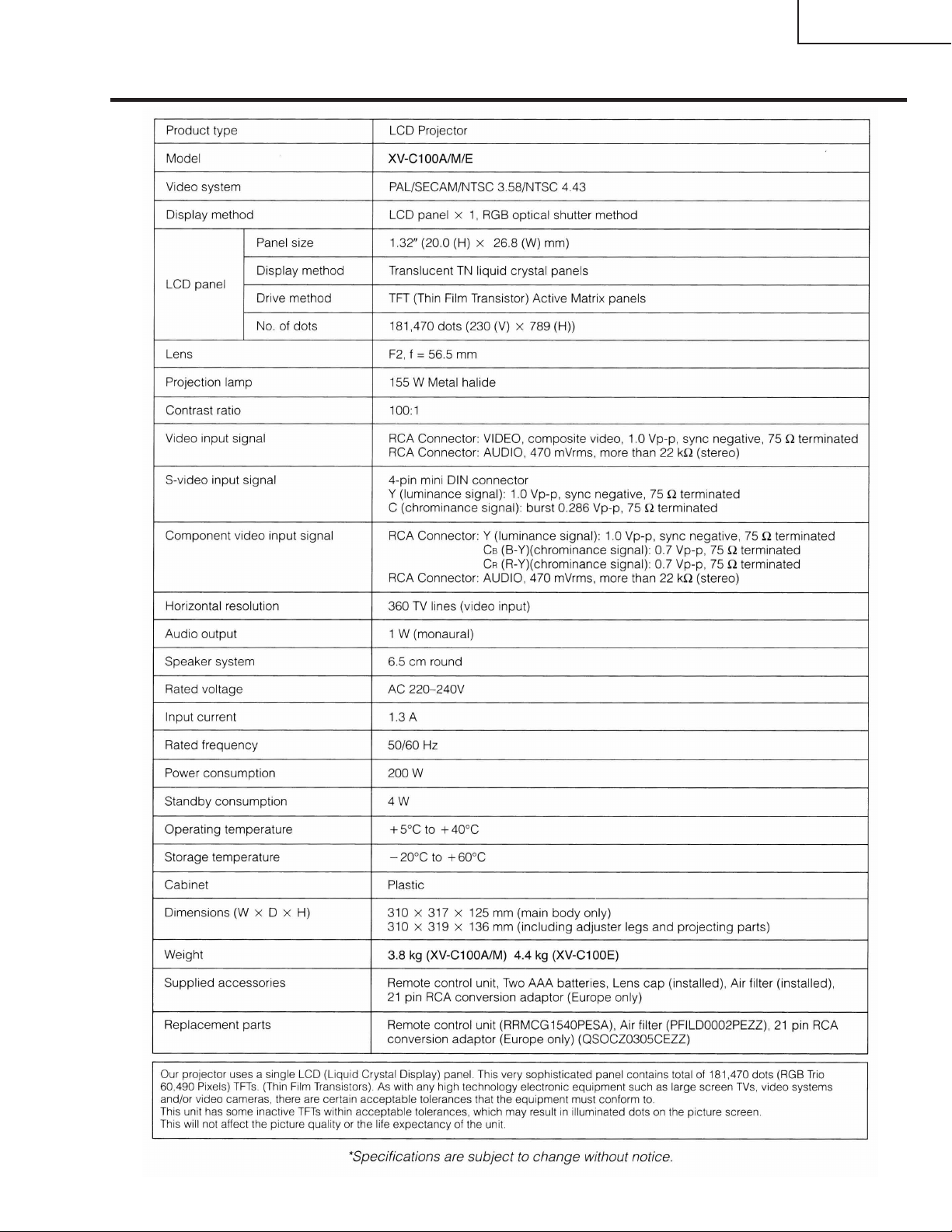
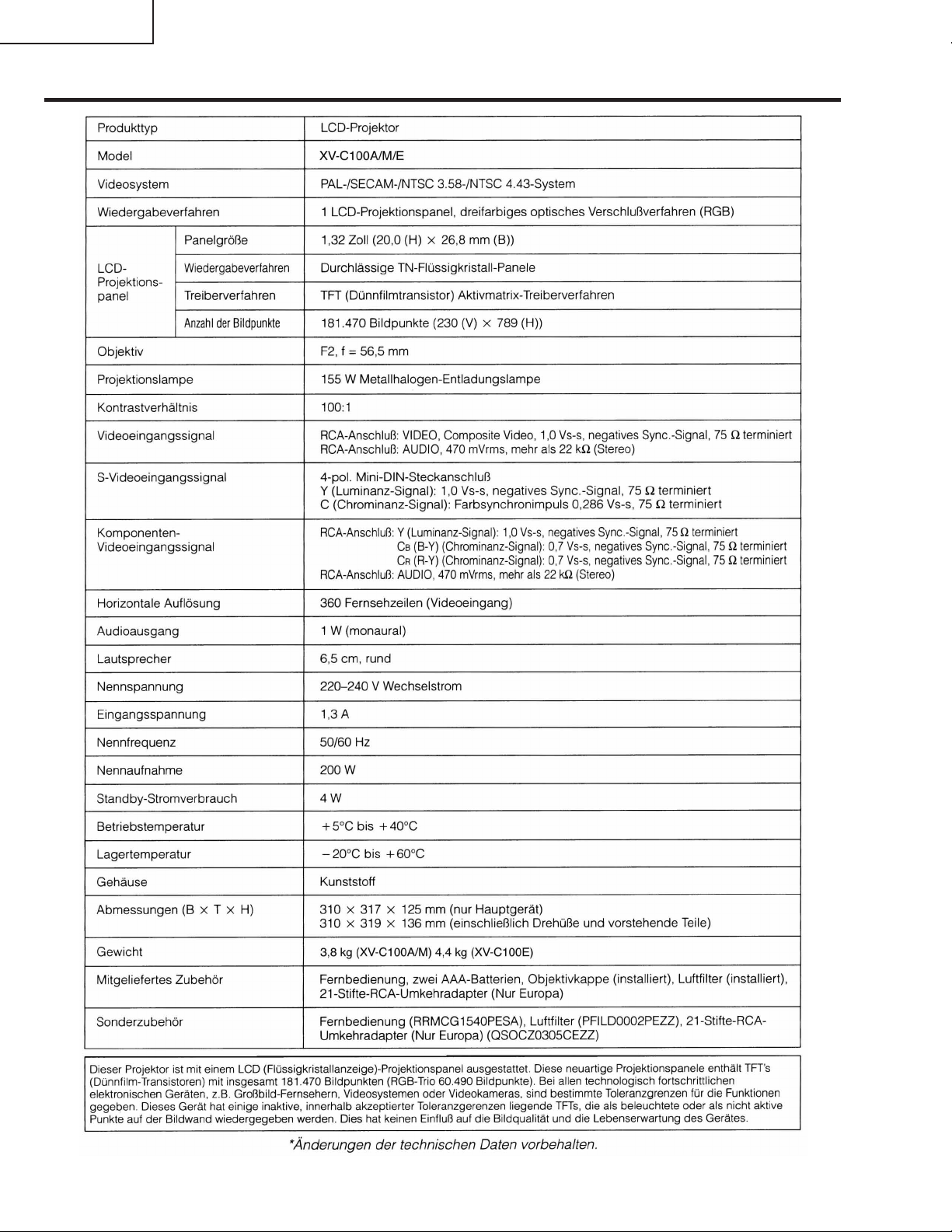
Specifications
XV-C100A/M/E
3
Page 4
XV-C100A/M/E
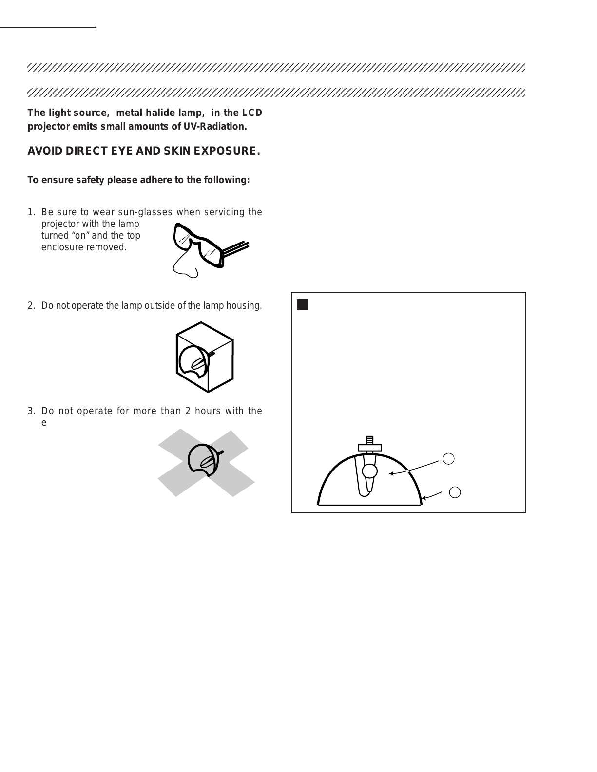
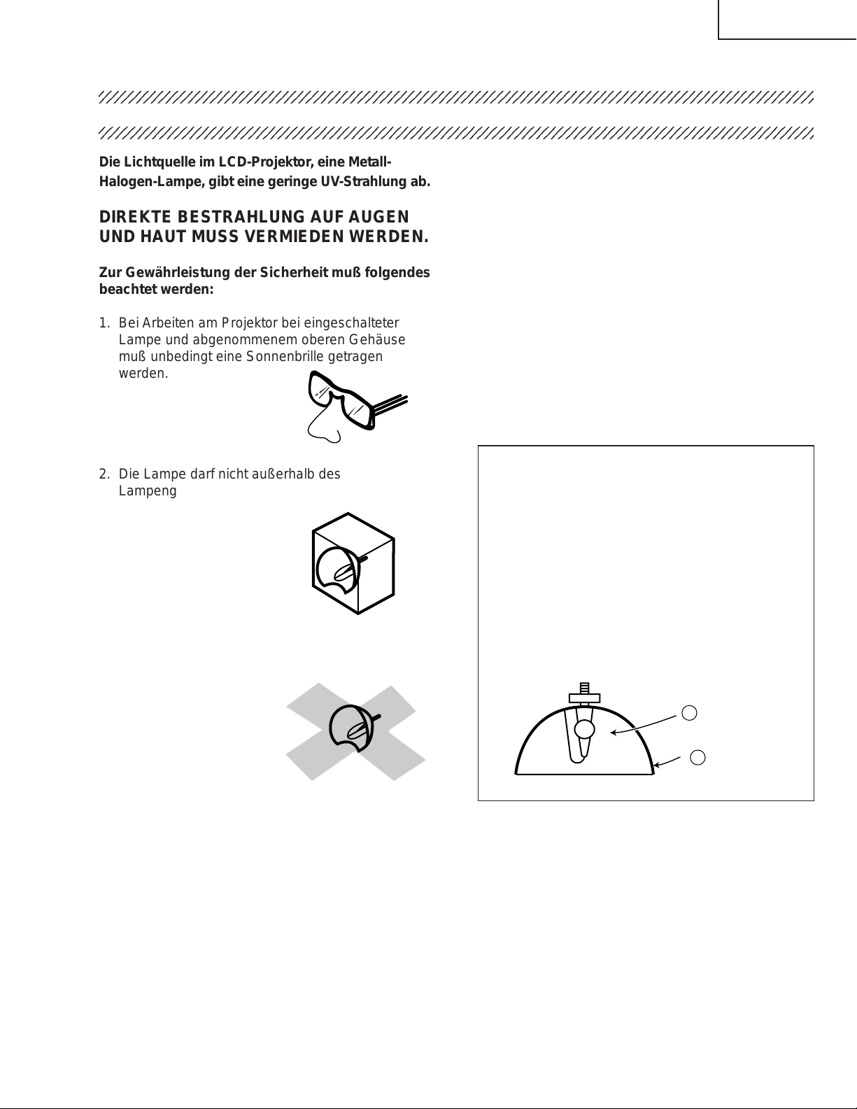
NOTE TO SERVICE PERSONNEL
UV-RADIATION PRECAUTION
The light source, metal halide lamp, in the LCD
projector emits small amounts of UV-Radiation.
A VOID DIRECT EYE AND SKIN EXPOSURE.
To ensure safety please adhere to the following:
1. Be sure to wear sun-glasses when servicing the
projector with the lamp
turned “on” and the top
enclosure removed.
2. Do not operate the lamp outside of the lamp housing.
3. Do not operate for more than 2 hours with the
enclosure removed.
UV-Radiation and Medium Pressure
Lamp Precautions
1. Be sure to disconnect the AC plug when replacing
the lamp.
2. Allow one hour for the unit to cool down before
servicing.
3. Replace only with same type lamp. Type
CLMPF0053DE03 rated 65V/155W.
4. The lamp emits small amounts of UV-Radiation,
avoid direct-eye contact.
5. The medium pressure lamp involves a risk of
explosion. Be sure to follow installation instructions
described below and handle the lamp with care.
Lamp Replacement
Note:
Since the lamp reaches a very high temperature
during units operation replacement of the lamp should
be done at least one hour after the power has been
turned off. (to allow the lamp to cool off.)
Installing the new lamp, make sure not to touch the
lamp (bulb) replace the lamp by holding its reflector
2.
[Use original replacement only.]
Lamp
1
Reflector
2
DANGER ! –– Never turn the power on without
the lamp to avoid electric-shock or damage of the
devices since the stabilizer generates high voltages
at its start.
4
Page 5

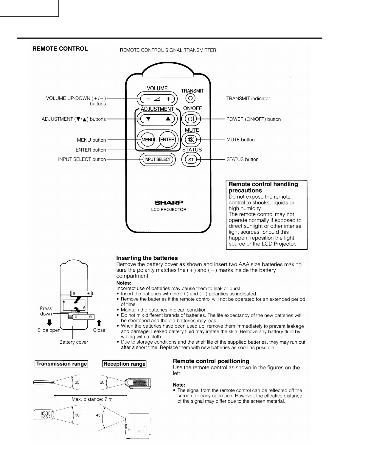
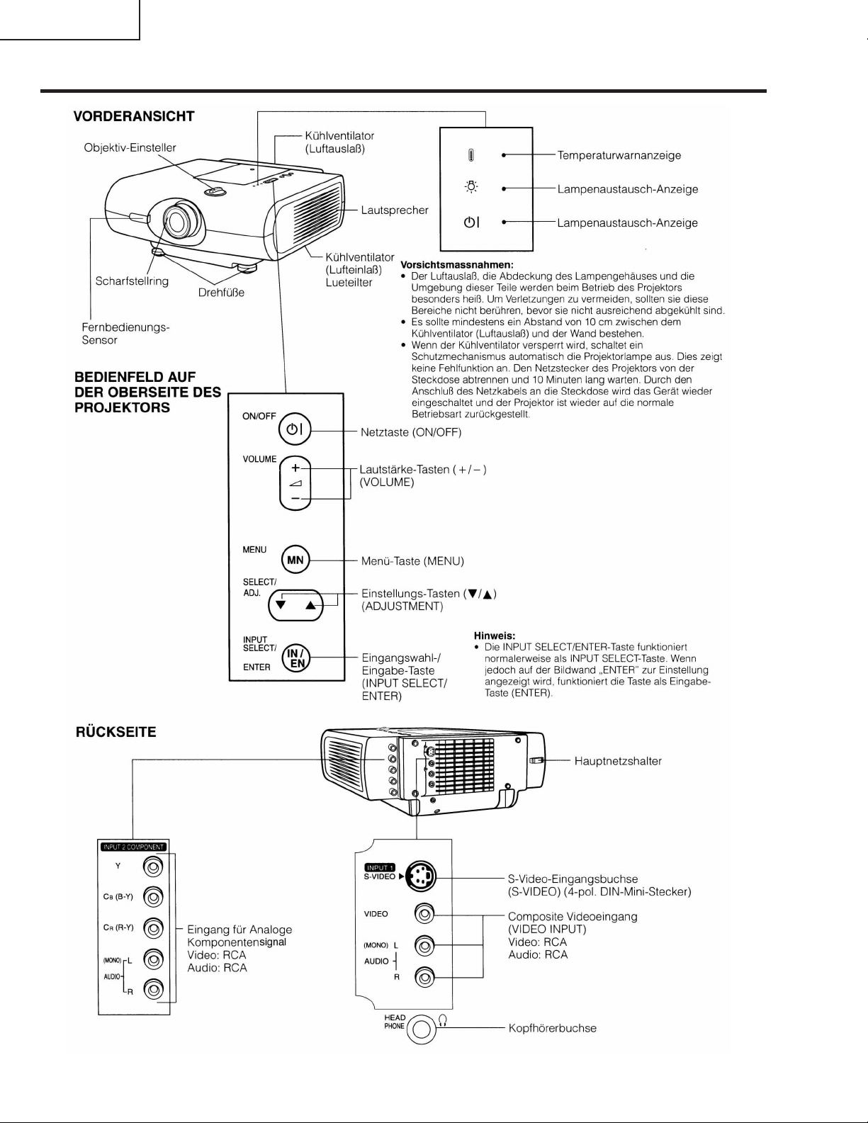
Location of Controls
XV-C100A/M/E
5
Page 6
XV-C100A/M/E
Remote Control Operation
6
Page 7
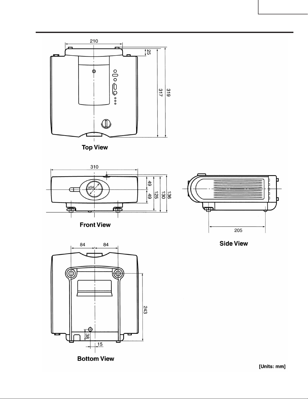
Dimensions
XV-C100A/M/E
7
Page 8
XV-C100A/M/E
Rear Cabinet
1-4
1-5
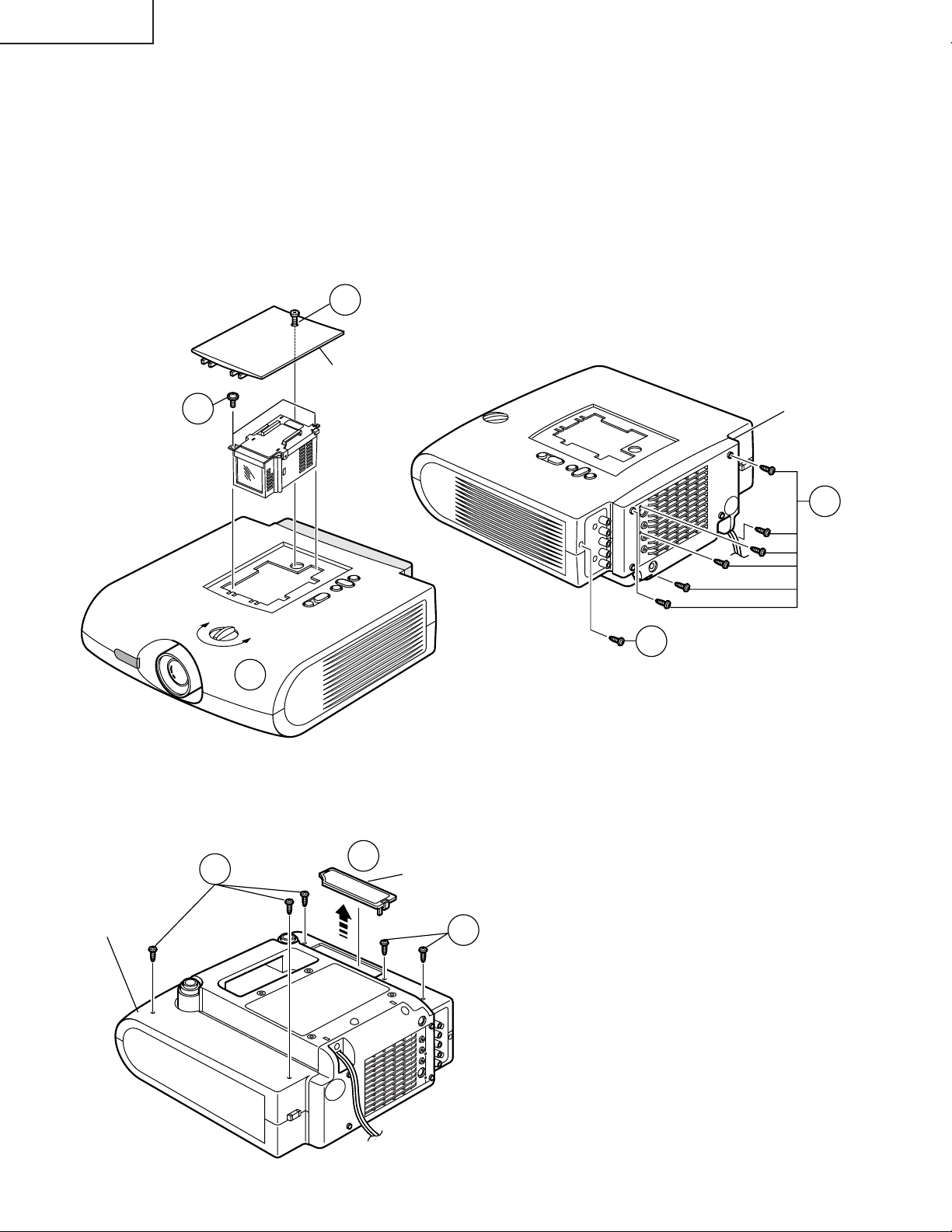
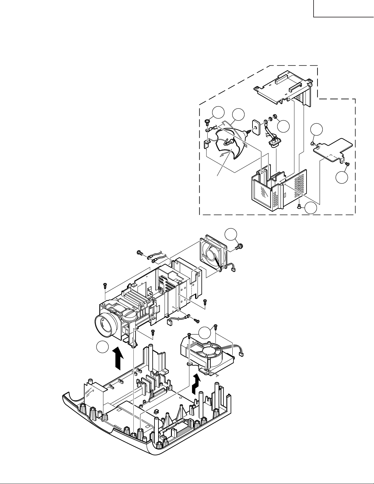
REMOVAL OF MAJOR COMPONENTS
1. Removing the cabinets
1-1. Remove the screw and detach the lamp cage cover.
1-2. Remove the two lock screws (two 4-mm screws) off the lamp/cage module unit.
1-3. Turn the lens shift dial until the lens comes to almost the center of the lens hole in the front cabinet.
1-4. Remove the six screws (six 3-mm tapping screws) off the rear cabinet.
1-5. Remove the M3 tapping screw off the sub unit cover.
1-1
Lamp Cage Cover
1-2
Lamp/Cage Module Unit
1-3
1-6. Remove the air filter cover.
1-7. Remove the five tapping screws off the bottom cabinet.
1-7
Bottom Cabinet
1-6
Air Filter Cover
1-7
8
Page 9
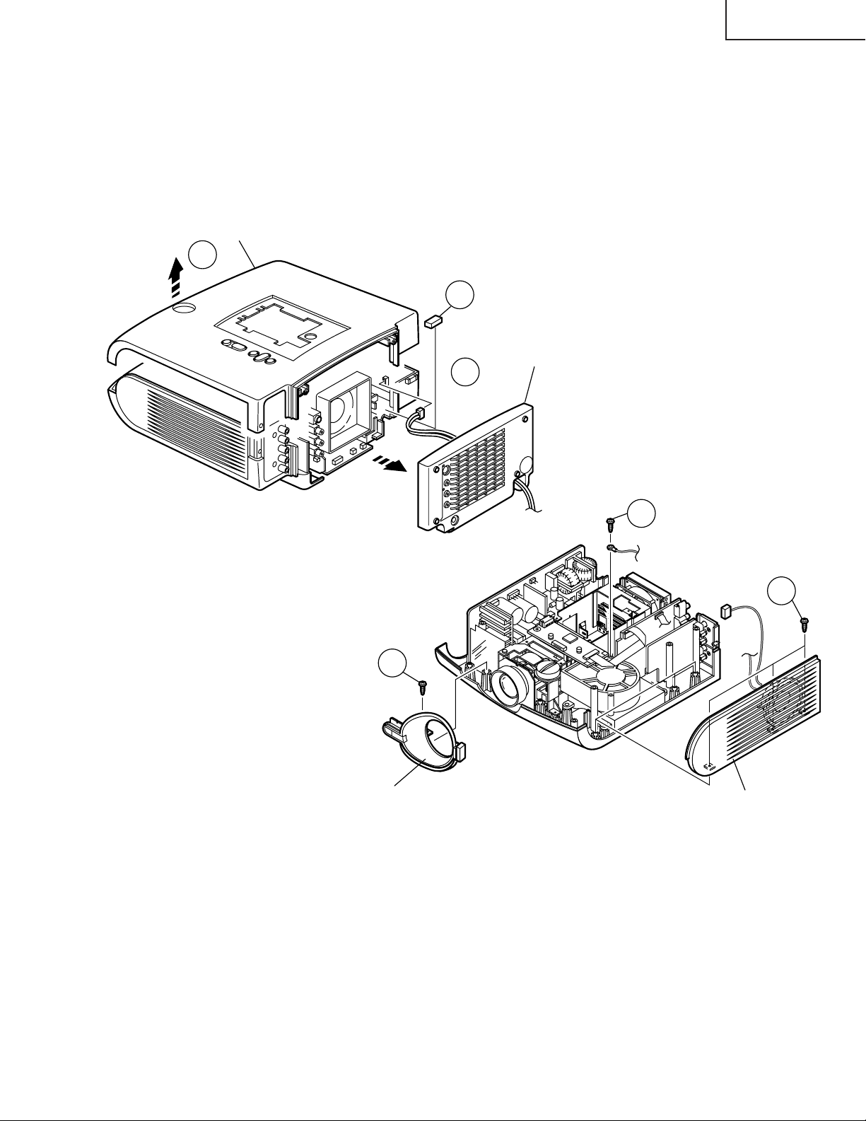
Top Cabinet
1-8
XV-C100A/M/E
1-8. Now lift the top cabinet further up and
disconnect the leaf switch connectors (LL) as
well as the operation key unit flat cable (KE).
The top cabinet is now free.
1-9. Disconnect the connector (PE) of the AC cord
(that runs through the rear cabinet) from the
ballast unit. Detach the rear cabinet.
1-10. Remove the spacer.
1-11. Remove the screws off the lens Cover.
1-12. Disconnect the speaker connector (SP) and
remove the three lock screws. Remove the
screw off the ground lead. Now detach the side
cover.
1-10
Rear Cabinet
1-9
(PE)
1-12
1-11
Lens Cover
Reassembling procedure
1. Fit the lens cover and the side cover to the bottom panel. Tighten up the related screws.
2. Set the top cabinet over the bottom cabinet.
(SP)
Side Cover
1-12
3. Tighten up the M3 tapping screw into the sub unit cover.
4. Press the rear cabinet against the top and bottom cabinets to fit them together.
5. Tighten up the screws into the rear cabinet. Use the six 3-mm tapping screws.
6. Tighten up the tapping screws to fix the top and bottom cabinets.
7. Put the lamp/cage module unit into position. Tighten up the two 4-mm screws.
8. Place the lamp cage cover and tighten up the screws.
9
Page 10
XV-C100A/M/E
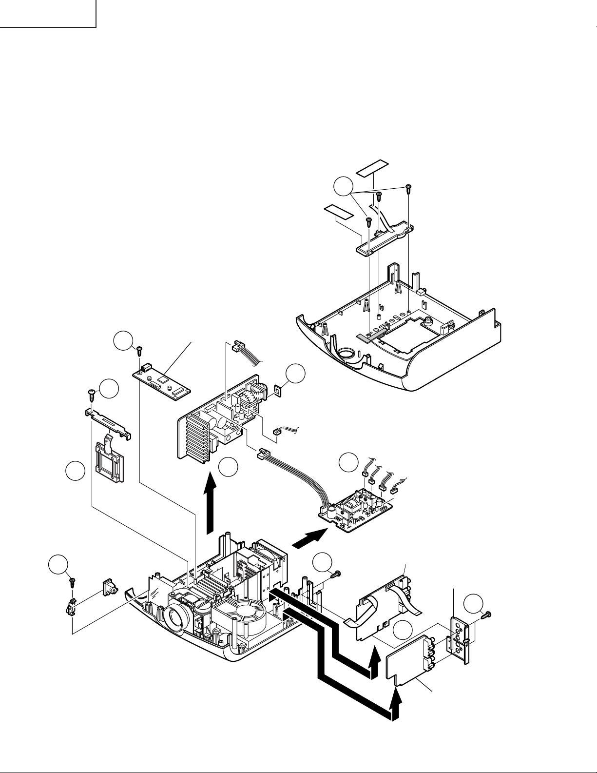
2. Removing the PWBs
2-1. Slide out the power unit, ballast unit, main unit in their directions of arrow. Disconnect the connectors.
2-2. Remove the three screws, peel off the two pieces of tape, and take out the operation key unit.
2-3. Remove the screw off the control unit and R/C Receiver unit and sub unit. Disconnect the connectors.
2-4. Remove the button cover.
3. Removing the LCD module unit
3-1. Remove the screw off the panel cover. Take out the panel cover.
3-2. Pull up the LCD module unit slowly out of position.
2-2
Operation Key Unit
Panel Cover
3-2
2-3
2-3
3-1
LCD
Module Unit
R/C Receiver
Unit
Control Unit
2-1
2-4
Ballast Unit
2-3
Top Cabinet
2-1
Power Unit
Main Unit
Sub Unit Cover
2-3
10
2-1
Sub Unit
Page 11
XV-C100A/M/E
4. Removing the optics mechanism assembly
4-1. Remove the four screws off the optics mechanism assembly. Detach the assembly from the bottom cabinet.
4-2. Remove the four screws off the intake duct assembly. Detach the intake duct assembly from the bottom
cabinet.
4-3. Remove the two screws off the cooling fan.
5.Removing the lamp
5-1. Remove the three countersunk lock screws off
the upper and lower lamp cases.
5-2. Remove the lock screw and the nut off the lamp
terminal.
5-3. Release the lamp lock spring off the hook below
the lower lamp case. Take out the lamp/mirror
assembly.
5-2
Lamp/Mirror
Ass'y
Lower Lamp Case
5-3
4-3
5-2
Lamp/Cage
Module Unit
Upper Lamp
Case
5-1
5-1
5-1
Optics Mecha
Ass'y
Bottom Cabinet Ass'y
Cooling Fan
(Exhaust Vent)
4-2
4-1
Intake Duct Ass'y
11
Page 12
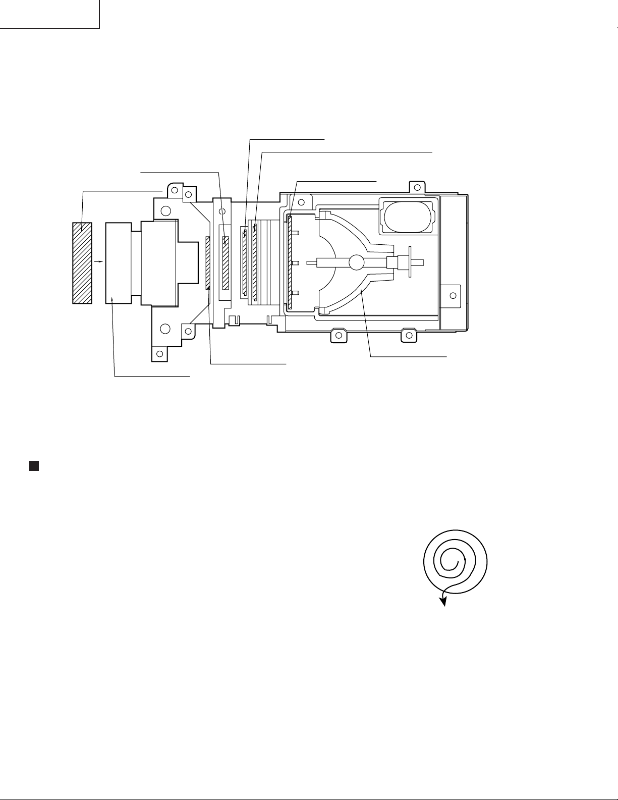
XV-C100A/M/E
Optical unit
RLCDP0088CEZZ
PCAPH1061CESB
Lens cap
LCD
OPTICAL SYSTEM
Polarizer Input plate
PFiLW0164CEZZ
PFiLW0202CEZZ
PFiLW0194CEZZ
UV/IR filter
Heat Management plate
PFiLW0200CEZZ
PLNS-0124CEZZ
Projection lens
Diffraction grating
Cleaning the lenses and reflectors
1. Lens cleaner
• Cleaning liquid:
Change the mixture ratio of alcohol and ether depending on ambient
temperatures. Make sure that the liquid evaporates from the lens
surface immediately after you rub it: This is the best ratio. The more
ether is used, the quicker the liquid evaporates.
• Method:
Use well-washed bleached cotton cloth or cleaning paper available
on the market. Damp the bleached cotton cloth with the liquid, and
hold the lens sandwiched in the cloth with your thumb and the index
finger. Turn the lens and wipe the surface clean from the center
outward to collect dust. Be careful not to rub the coated surface too
strong.
CLMPF0053DE03
Lamp/Mirror Ass'y
12
Page 13
Ë
Controlling the total operating hours of the lamp
The following control is carried out when the lamp has been used for 1,900 hours and 2,000 hours.
1. After 1900-hour use
When the power is turned on, "LAMP" appears in the on-screen display for about 1 minute (flashing in yellow)
and the lamp LED indicator lights up in red.
When the 1,900-hour point comes up during use of the unit, the "LAMP" display starts flashing in yellow on the
screen for 1 minute at the very 1,900-hour point.
Now the lamp LED indicator changes from green to red.
2. After 2000-hour use
When the power is turned on, "LAMP" appears in the on-screen display for 5 minutes (flashing in red) and the
lamp LED indicator lights up in red. Five minutes thereafter, the power turns itself of f and the unit is interrupted.
When the 2,000-hour point comes up during use of the unit, the "LAMP" display starts flashing in red on the
screen for 5 minutes at the very 2,000-hour point. Five minutes later, the power turns itself off and the unit is
interrupted. (The lamp LED indicator stays red since the 1,900-hour point.)
If you try to turn on the power twice after the 2,000-hour point, the unit remains off.
3. When the 2,000-hour point comes up, take the following steps.
Replace the lamp with new one. While holding down both the "VOLUME "" and "SELECT/ADJ "" Keys on the
unit, turn on the main power switch (located on the back of the unit). The lamp operating hourmeter is now reset
to zero. Turn on the unit and make sure the time display shows "0000H".
XV-C100A/M/E
4. Displaying the total operating hours of the lamp
Change the STATUS3 data settings: PICTURE at 0, BRIGHT at MAX, COLOR at MIN, TINT at MIN, and
SHARPNESS at MAX. Hold down the SOUND DOWN and ENTER keys for longer than 2 seconds. By doing
this, the total operating hours will be displayed on the screen.
TIME
0000H
TOTAL TIME
0000H
13
Page 14
XV-C100A/M/E
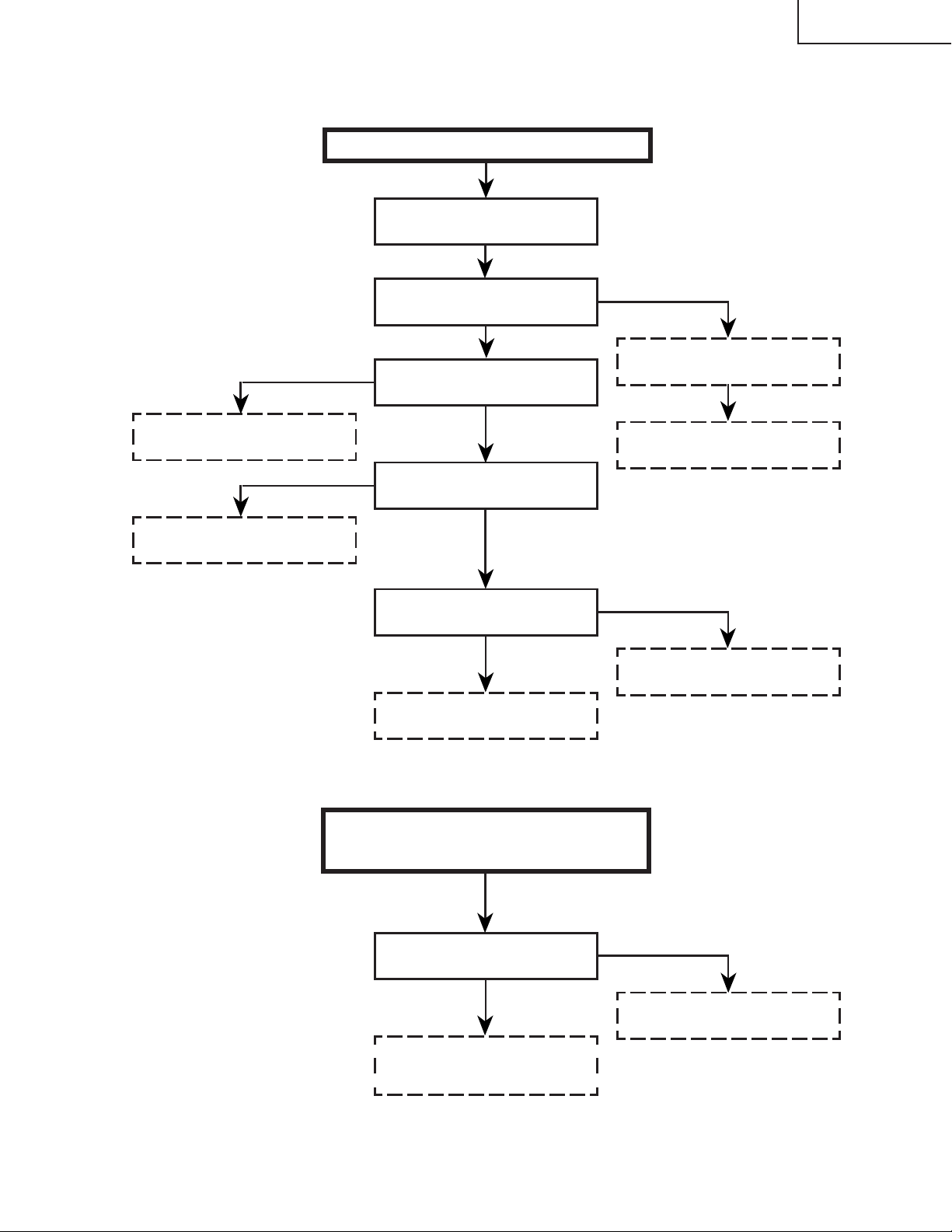
ADJ. IN (adjustment input) FUNCTION
1. Keys used for the adjustments
On the sub PWB: S2001
Control keys: [ENTER], [MENU], [SELECT/ADJ.'], [SELECT/ADJ."], [VOLUME+]
2. Operation
Press S2001 to call up the ADJ IN mode.
Use the [SELECT/ADJ. '] and [SELECT/ADJ."] keys to select an adjustment group, and press the
[ENTER] key.
Use the [SELECT/ADJ. '] and [SELECT/ADJ."] keys again to select an adjustment subject, and
press the [ENTER] key.
The [SELECT/ADJ. '] and [SELECT/ADJ."] keys are also used to make adjustments.
Each time the [ENTER] key is pressed on the ADJ IN screen, the adjustment subjects of a group are
changed one by one. (Pressing the [VOLUME + ] key changes the subjects in the reverse order.)
When the [MENU] key is pressed, the previous group appears on the screen.
Press S2001 again to go out of the ADJ IN mode.
Group
Adjustment
subjects
VIDEO 1
H-CENT
P-H-CENT
CONT
BRIGHT
SUB-R
SUB-G
SUB-B
VIDEO 2
SUB-BIAS
R-BIAS
B-BIAS
R-DRIVE
B-DRIVE
TINT
COLOR
P-COLOR
S-COLOR
VIDEO 3
GAMMA1
GAMMA2
AGCADJ
T-BRT
VIDEO 4
C-CONT
C-BRIGHT
C-COLOR
C-TINT
C-H-CENT
C-PH-CENT
SET
HL
The adjustment group "LINE" is not used here.
Do not feed the signal when the adjustment group "N • W" is used.
N • W
RED
GREEN
BLUE
N • W
LINE
AUTO
OFF TIMER
TEMP1
TEMP2
FACTORY SET4
TEST
TIME1
TIME2
14
Page 15

3. Adjustment subjects
VIDEO 1
H-CENT NTSC horizontal position adjustment
P-H-CENT P AL horizontal position adjustment
CONT Sub-contrast adjustment
BRIGHT Brightness adjustment
SUB-R Not used, just to be 0 (zero)
SUB-G Not used, just to be 0 (zero)
SUB-B Not used, just to be 0 (zero)
VIDEO 2
SUB-BIAS Sub-bias adjustment
R-BIAS White balance (red), bias adjustment
B-BIAS White balance (blue), bias adjustment
R-DRIVE White balance (red), drive adjustment
B-DRIVE White balance (blue), drive adjustment
TINT TINT adjustment
COLOR Colour level adjustment
P-COLOR PAL colour level adjustment
S-COLOR SECAM colour level adjustment
XV-C100A/M/E
VIDEO 3
GAMMA1 Gamma correction 1
GAMMA2 Gamma correction 2
AGC ADJ AGC adjustment
T-BRT Chroma IC brightness adjustment
VIDEO 4
C-CONT Component input contrast adjustment
C-BRIGHT Component input brightness adjustment
C-COLOR Component input colour level adjustment
C-TINT Component input tint adjustment
C-H-CENT Component input NTSC horizontal position adjustment
C-PH-CENT Component input PAL horizontal position adjustment
SET
HL Temperature detection level setting
N • W (Single-colour display)
RED Red
GREEN Green
BLUE Blue
N • W Not used
TEST
TIME1 1-hour increment setting for total lamp timer
TIME2 1899H-1999H-0H-1899H setting for total lamp timer
15
Page 16
XV-C100A/M/E
0
SUB-B
FLOWCHART OF ADJUSTMENT
–4
S-COLOR
–6
P-COLOR
+7
C-PH-CENT
HL
2
0
SUB-G
0
SUB-R
–3
BRIGHT
+6
CONT
0
P-H-CENT
64
B-DRIVE
64
R-DRIVE
74
B-BIAS
74
R-BIAS
COLOR
TINT
T-BRT
ADJ
AGC
GAMMA2
–4
–3
–30
0
0
+5
C-H-CENT
+9
C-TINT
+7
C-COLOR
+5
C-BRIGHT
Not used
0000
TIME2
ENTER
H-CENT SUB-R
VIDEO1
H-CENT
MENU
P-H-CENT SUB-G
CONT SUB-B
–3
BRIGHT
SUB-BIAS
MENU
ENTER
TINT
COLOR
P-COLOR
SUB-BIAS
R-BIAS
B-BIAS
VIDEO2
User mode screen
64
S-COLOR
R-DRIVE
B-DRIVE
S2001
ENTER
ENTER
MENU
VIDEO1 SET
VIDEO2 N • W
ADJ IN
255
GAMMA1
MENU
GAMMA1
GAMMA2
AGC ADJ
VIDEO3
VIDEO3 LINE
VIDEO4 TEST
T-BRT
ENTER
C-PH-CENT
C-CONT
C-BRIGHT
VIDEO4
–4
C-CONT
MENU
C-COLOR
C-TINT
C-H-CENT
16
ENTER
N • W
RED
R G B N • W
MENU
GREEN
BLUE
N • W
LINE
AUTO
OFF TIMER
TEMP1
TEMP2
ENTER
Not used
FACTORY SET 4
TEST
TIME1
MENU
TIME1
TIME2
0001
Page 17
XV-C100A/M/E
ELECTRICAL ADJUSTMENT
No. Adjustment Item Adjustment Conditions Adjustment Procedure
1
NTSC freerunning
frequency
(R1616)
2
PAL freerunning
frequency
(R1602)
3
Horizontal
center (NTSC)
(DAC)
4
Horizontal
center (PAL)
(DAC)
1.Receive the NTSC monoscope pattern
signal.
2.Hold down S801.
1. Receive the PAL monoscope pattern
signal.
2. Hold down S801.
1. Receive the NTSC monoscope pattern
signal.
2. Press S2001 to call up the ADJ IN
mode and select the following subject.
Group: VIDEO 1
Subject: H-CENT
1. Receive the PAL monoscope pattern
signal.
2. Press S2001 to call up the ADJ IN
mode and select the following subject.
Group: VIDEO 1
Subject: P-H-CENT
• Turn R1616 until the image appears
as specified.
• Turn R1602 until the image appears
as specified.
• Using the ' and " keys, make the
overscan just the same at right and
left.
Overscan: 91-97%
• Using the ' and " keys, make the
overscan just the same at right and
left.
Overscan: 91-97%
5
Contrast (DAC)
(gamma
correction off)
1. Receive the NTSC 10-step pattern
signal.
2. Connect a dual-beam oscilloscope
between pin (2) of P1401 and GND.
3. Press S2001 to call up the ADJ IN
mode and select the following subject.
Group: VIDEO 2
Subject: SUB-BIAS
4. Using the ' and " keys, put the
waveform to its proper shape.
5. Press S2001 again to call up the ADJ
IN mode and select the following
subject.
Group: VIDEO 1
Subject: SUB-R, SUB-G, SUB-B
Make sure all these subjects have an
entry of 0 (zero).
6. Adjust R861 to get the highest gain.
7. Finally select the following subject.
Group: VIDEO 1
Subject: CONT
• Using the ' and " keys, adjust the
difference between the tenth-step
level and the pedestal level to
6.0±0.15 Vp-p.
10
17
Page 18
XV-C100A/M/E
No. Adjustment Item Adjustment Conditions Adjustment Procedure
6
Automatic gain
control: R861
(gamma
correction off)
7
Brightness
(DAC)
(gamma
correction on)
1. Receive the NTSC 10-step pattern
signal.
2. Connect the dual-beam oscilloscope
between pin (2) of P1401 and GND.
3. Select the following subject.
Group: VIDEO 1
Subject: CONT
1. Receive the NTSC 10-step pattern
signal.
2. Connect the dual-beam oscilloscope
between pin (2) of P1401 and GND.
3. Press S2001 to call up the ADJ IN
mode and select the following subject.
Group: VIDEO 1
Subject: BRIGHT
• Turn R861 so that the difference
between the 100% white level and the
pedestal level be 4.8±0.05 Vp-p.
10
• Using the ' and " keys, adjust the
difference between the first-step
level and the tenth-step level to
2.0±0.05 Vp-p.
10
1
8
Component
contrast (DAC)
(gamma
correction off)
9
Component
brightness
(DAC)
(gamma
correction on)
1. Feed the NTSC 10-step pattern signal
to the component terminal.
2. Connect the dual-beam oscilloscope
between pin (2) of P1401 and GND.
3. Press S2001 to call up the ADJ IN
mode and select the following subject.
Group: VIDEO 4
Subject: C-CONT
1. Feed the NTSC 10-step pattern signal
to the component terminal.
2. Connect the dual-beam oscilloscope
between pin (2) of P1402 and GND.
3. Press S2001 to call up the ADJ IN
mode and select the following subject.
Group: VIDEO 4
Subject: C-BRIGHT
• Using the ' and " keys, adjust the
difference between the 100% white
level and the pedestal level be
4.8±0.05 Vp-p.
10
• Using the ' and " keys, adjust the
difference between the first-step
level and the tenth-step level to
2.0±0.05 Vp-p.
10
1
18
Page 19
XV-C100A/M/E
No. Adjustment Item Adjustment Conditions Adjustment Procedure
10
Tint (DAC)
11
Component tint
(DAC)
1. Receive the NTSC half-colour bar
signal.
2. Press S2001 to call up the ADJ IN
mode and select the following subject.
Group: VIDEO 2
Subject: TINT
3. Connect the dual-beam oscilloscope
between pin (5) of P803 and GND.
1. Feed the NTSC half-colour bar signal
to the component terminal.
2. Press S2001 to call up the ADJ IN
mode and select the following subject.
Group: VIDEO 4
Subject: C-TINT
3. Connect the dual-beam oscilloscope
between pin (3) of P803 and GND.
• Using the ' and " keys, adjust the
(B-Y) signal waveform to slope down
straight.
• Using the ' and " keys, adjust the
(B-Y) signal waveform to slope down
straight.
12
Sub-bias (DAC)
(gamma
correction on)
13
R-drive
B-drive
1. Receive the NTSC 10-step pattern
signal.
2. Connect the dual-beam oscilloscope
between pin (2) of P1401 and GND.
3. Press S2001 to call up the ADJ IN
mode and select the following subject.
Group: VIDEO 2
Subject: SUB-BIAS
1. Receive the NTSC 10-step pattern
signal.
2. Connect the dual-beam oscilloscope
between pin (3)(R) (or pin (1)(B)) of
P1401 and GND.
3. Press S2001 to call up the ADJ IN
mode and select the following subject.
Group: VIDEO 2
Subject: R-DRIVE, B-DRIVE
• Using the ' and " keys, adjust the
difference between the white levels
to 3.0±0.05 Vp-p.
• Using the ' and " keys, adjust the
difference between the first-step
level and the tenth-step level to
2.0±0.05 Vp-p.
19
Page 20
XV-C100A/M/E
No. Adjustment Item Adjustment Conditions Adjustment Procedure
14 • Using the ' and " keys, adjust the
R-bias
B-bias
15
NTSC colour
(DAC) (gamma
correction on)
1. Receive the NTSC 10-step pattern
signal.
2. Connect the dual-beam oscilloscope
between pin (3)(R) (or pin (1)(B)) of
P1401 and GND.
3. Press S2001 to call up the ADJ IN
mode and select the following subject.
Group: VIDEO 2
Subject: R-BIAS, B-BIAS
1. Receive the NTSC half-colour bar
signal.
2. Connect the dual-beam oscilloscope
between pin (3) of P1401 and GND.
3. Press S2001 to call up the ADJ IN
mode and select the following subject.
Group: VIDEO 2
Subject: COLOR
difference between the white levels
to 3.0±0.05 Vp-p.
• Using the ' and " keys, adjust the
difference between the 100% white
level and the primary red level to
0±0.05 Vp-p.
100% white
Primary red
16
PAL colour
(DAC) (gamma
correction on)
1. Receive the P AL half-colour bar signal.
2. Connect the dual-beam oscilloscope
between pin (3) of P1401 and GND.
3. Press S2001 to call up the ADJ IN
mode and select the following subject.
Group: VIDEO 2
Subject: P-COLOR
20
• Using the ' and " keys, adjust the
difference between the 100% white
level and the primary red level to
0.10±0.05 Vp-p.
100% white
Primary red
Page 21
XV-C100A/M/E
No. Adjustment Item Adjustment Conditions Adjustment Procedure
17
SECAM colour
(DAC) (gamma
correction on)
18
Component
colour (DAC)
1. Receive the SECAM half-colour bar
signal.
2. Connect the dual-beam oscilloscope
between pin (3) of P1401 and GND.
3. Press S2001 to call up the ADJ IN
mode and select the following subject.
Group: VIDEO 2
Subject: S-COLOR
1. Feed the NTSC half-colour bar signal
to the component terminal.
2. Press S2001 to call up the ADJ IN
mode and select the following subject.
Group: VIDEO 4
Subject: C-COLOR
• Using the ' and " keys, adjust the
difference between the 100% white
level and the red level to 0.10±0.05
Vp-p.
100% white
• Make sure that the setting is 12.
Primary red
19
Counter-bias
(R1402)
20
White balance
(DAC)
1. Receive the NTSC monoscope pattern
signal.
1. Receive the NTSC monoscope pattern
signal.
2. Press S2001 to call up the ADJ IN
mode and select the following subject.
Group: VIDEO 2
Subject: R-BIAS, B-BIAS
• Turn R1402 until the best contrast
is achieved.
• Using the ' and " keys, visually
adjust the white balance to best
position.
21
Page 22
XV-C100A/M/E
No. Adjustment Item Adjustment Conditions Adjustment Procedure
21
On-screen
display position
check (L2003)
22
Temperature
sensor setting
check
1. Receive the NTSC monoscope pattern
signal.
2. Press the SOUND UP/DOWN keys to
get the sound volume display bar on
the screen.
1. Press S2001 to call up the ADJ IN
mode and select the following group.
Group: SET
Subject: HL
• Turn L2003 so that the display bar
be well centered on the screen.
• Make sure that the setting is 2.
23
Component
horizontal
center (NTSC)
(DAC)
24
Component
horizontal
center (PAL)
(DAC)
1. Receive the NTSC monoscope pattern
signal.
2. Press S2001 to call up the ADJ IN
mode and select the following subject.
Group: VIDEO 4
Subject: C-H-CENT
1. Receive the PAL monoscope pattern
signal.
2. Press S2001 to call up the ADJ IN
mode and select the following subject.
Group: VIDEO 4
Subject: C-PH-CENT
• Using the ' and " keys, make the
overscan just the same at right and
left.
Overscan : 91-97%
• Using the ' and " keys, make the
overscan just the same at right and
left.
Overscan : 91-97%
22
Page 23
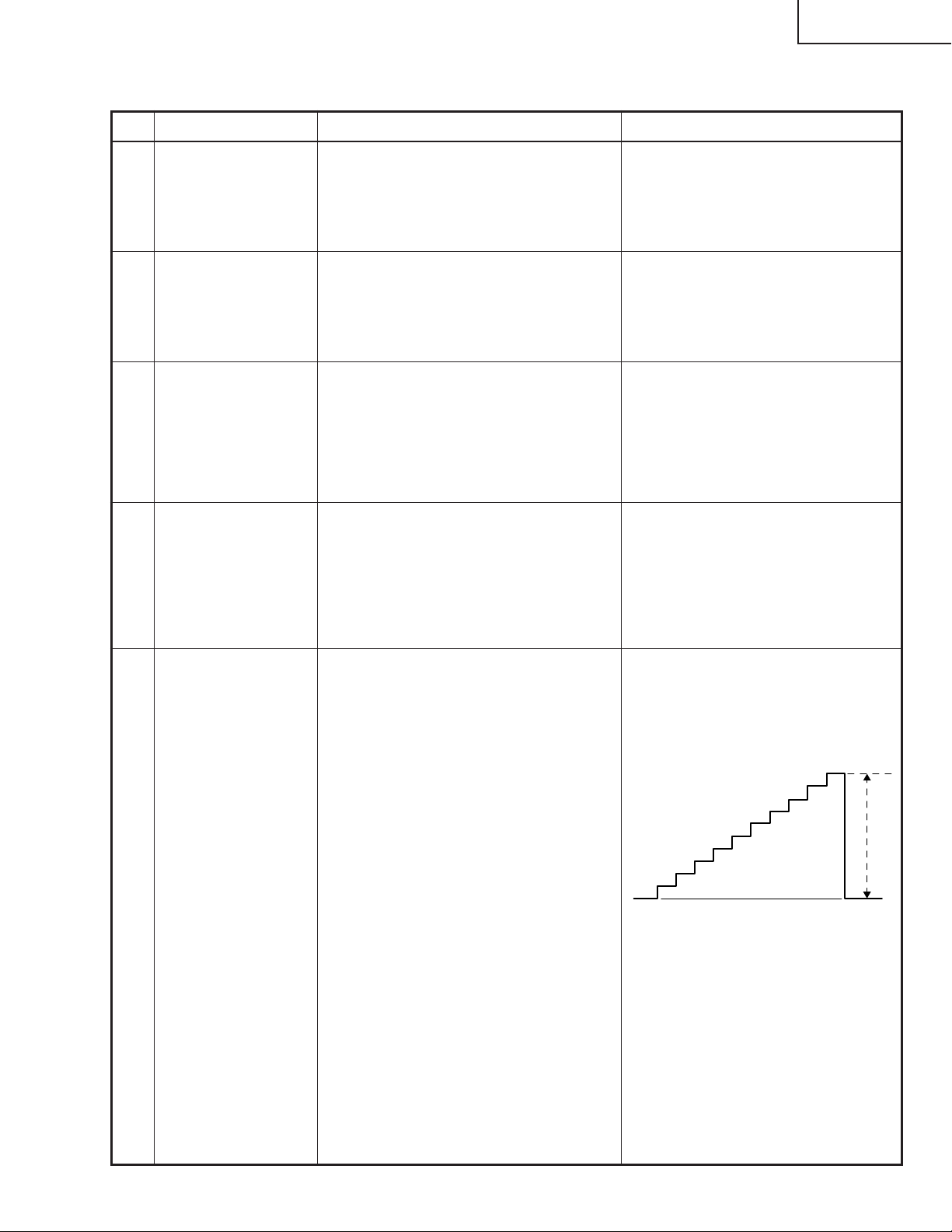
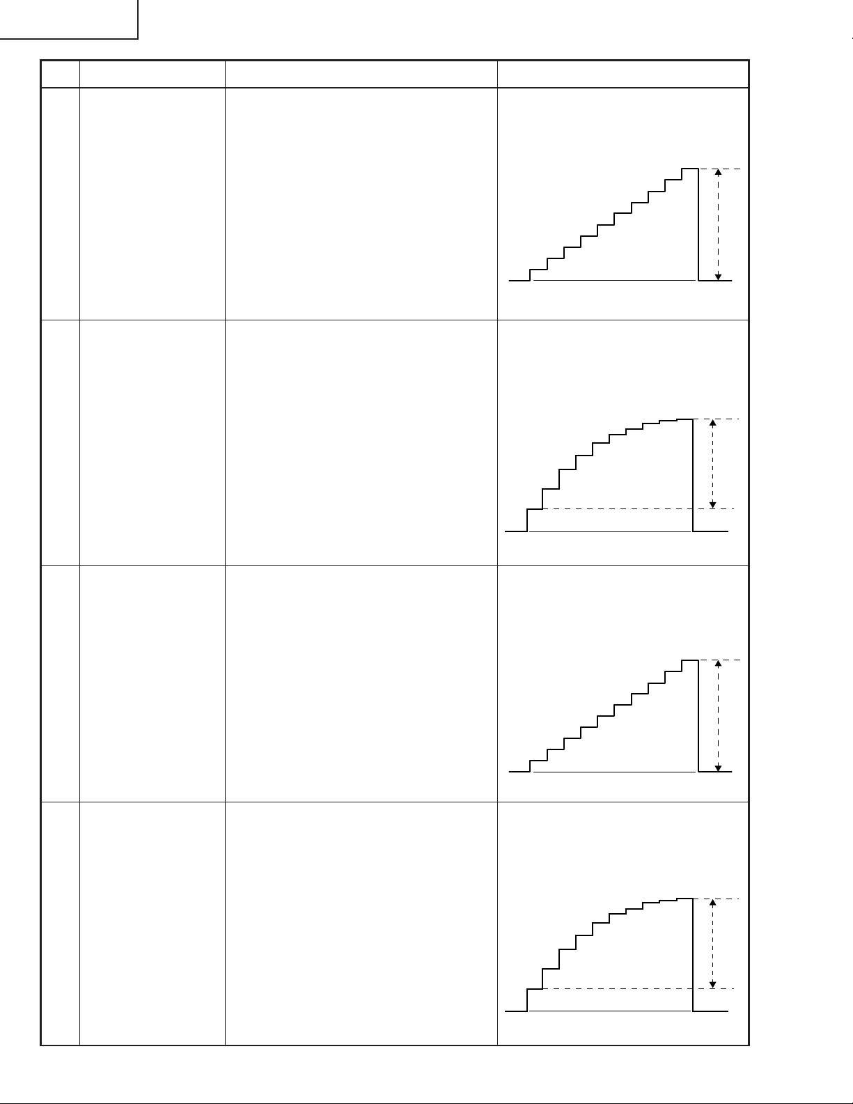
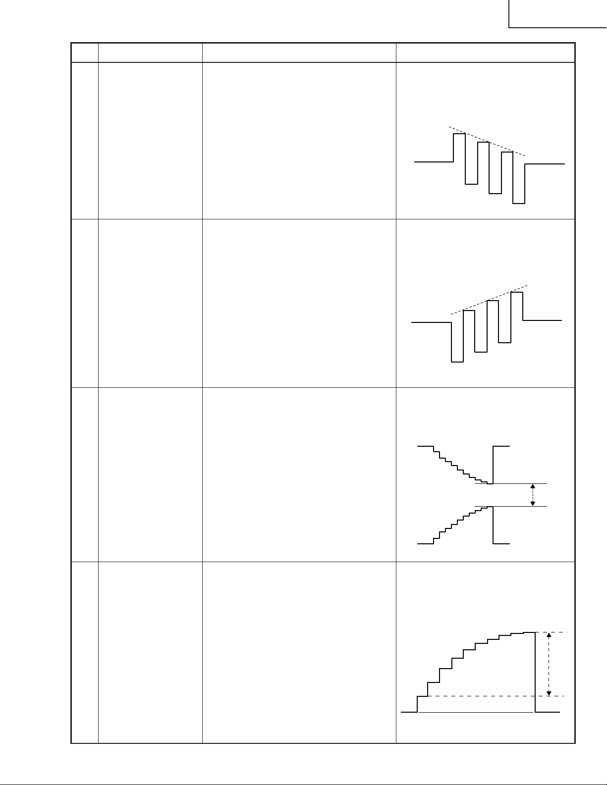
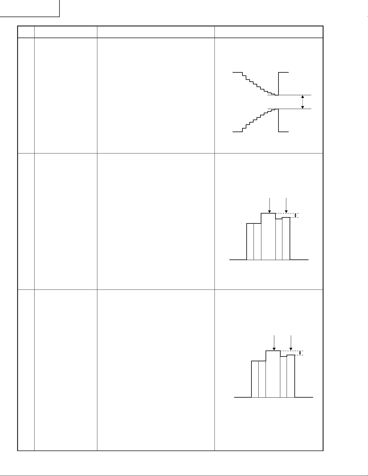
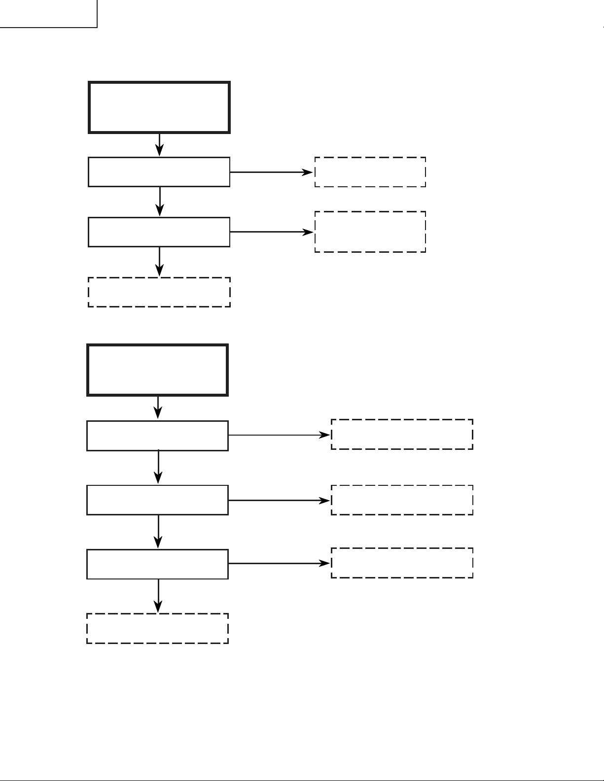
TROUBLE SHOOTING TABLE
Checking the video system
No picture
XV-C100A/M/E
Check the power unit.
Check IC401, DL401 and their
peripheral circuits.
No
No
Is the lamp on?
Yes
Is voltage applied at the EA
and EB connectors?
Yes
Is there signal at pins (21) and
(29) of IC801?
Yes
Is there signal at pins (1), (2) and (3)
of P803?
Yes
Go to "Checking the IC1501
interface circuit".
No
Check the lamp.
Check the ballast unit circuit.
No
Check IC801, IC804, Q801, Q802,
Q803 and their peripheral circuits.
No colour or poor tint with
NTSC signal
Is there chroma signal input at pin
(20) of IC801?
Yes
Check IC801, IC802, IC804 and their
peripheral circuits (X801 and C810 in
particular).
23
No
Check DL401, IC401, Q401 and their
peripheral circuits.
Page 24
XV-C100A/M/E
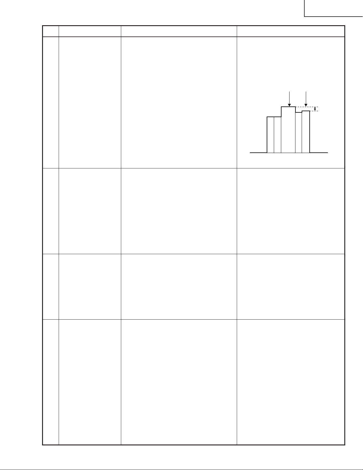
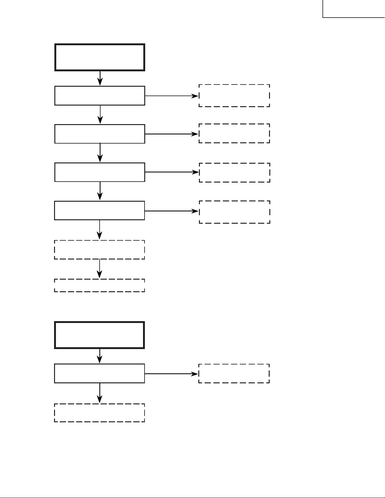
TROUBLE SHOOTING TABLE (Continued)
No colour or poor
tint with PAL
signal
Is there video signal input at pin (29)
of IC801?
Yes
Are R-Y and B-Y signals put out of
pins (45) and (46) of IC801?
Yes
Check IC802, IC804 and their
peripheral circuits.
No colour or poor
tint with SECAM
signal
Is there chroma signal input at pin
(20) of IC803?
No
No
No
Check IC401 and its
peripheral circuits.
Check IC801 and its
peripheral circuits (X802 and
C811 in particular).
Check IC401 and its peripheral
circuits.
Yes
Are there R-Y and B-Y signal outputs
at pins (11) and (12) of IC803?
Yes
Is voltage of over 4V fed to pin (49)
of IC801?
Yes
Check IC801, IC802, IC804 and their
peripheral circuits.
No
No
Check IC803 and its peripheral
circuits.
Check IC803 and its peripheral
circuits.
24
Page 25
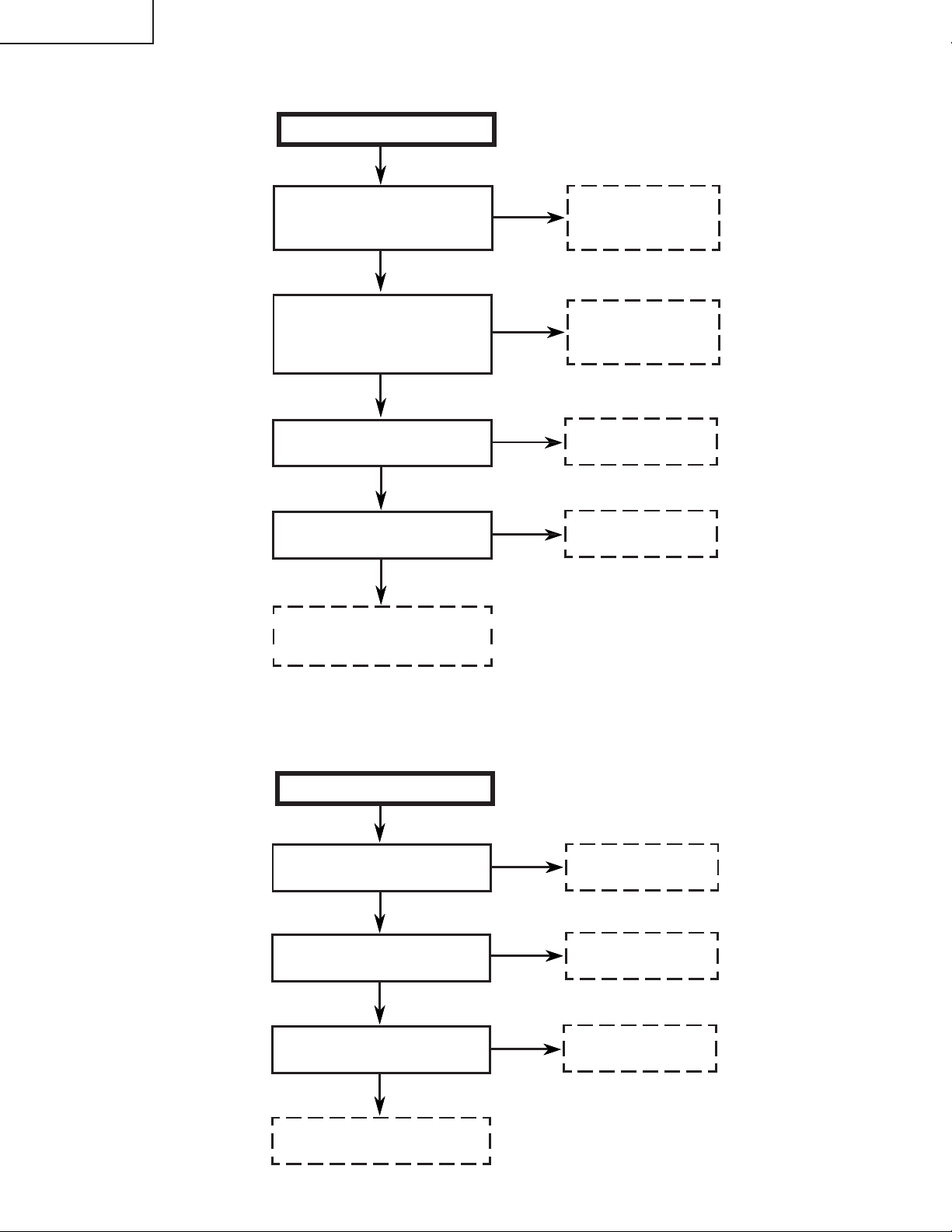
TROUBLE SHOOTING TABLE (Continued)
No component
picture
XV-C100A/M/E
Is there Y signal input at pin (35) of
IC3003?
Yes
Are there signal inputs at pins (13)
and (14) of IC3003?
Yes
Are there signal outputs at pins (44),
(45) and (46) of IC3003?
Yes
Are there signal inputs at pins (35),
(36) and (37) of IC801?
Yes
Check IC801 and its peripheral
circuits.
No
No
No
No
Check Q3001, Q3020,
Q3021 and their peripheral
circuits.
Check IC2001 and its
peripheral circuits.
Check IC3003 and its
peripheral circuits.
Check C830, C831, C832
and their peripheral circuits.
Check the IC1501 interface circuit.
No component
colour
Are there signal inputs at pins (33)
and (34) of IC3003?
Yes
Check IC3003 and its peripheral
circuits.
No
Check Q3006 thru Q3013
and Q3007 thru Q3010.
25
Page 26
XV-C100A/M/E
TROUBLE SHOOTING TABLE (Continued)
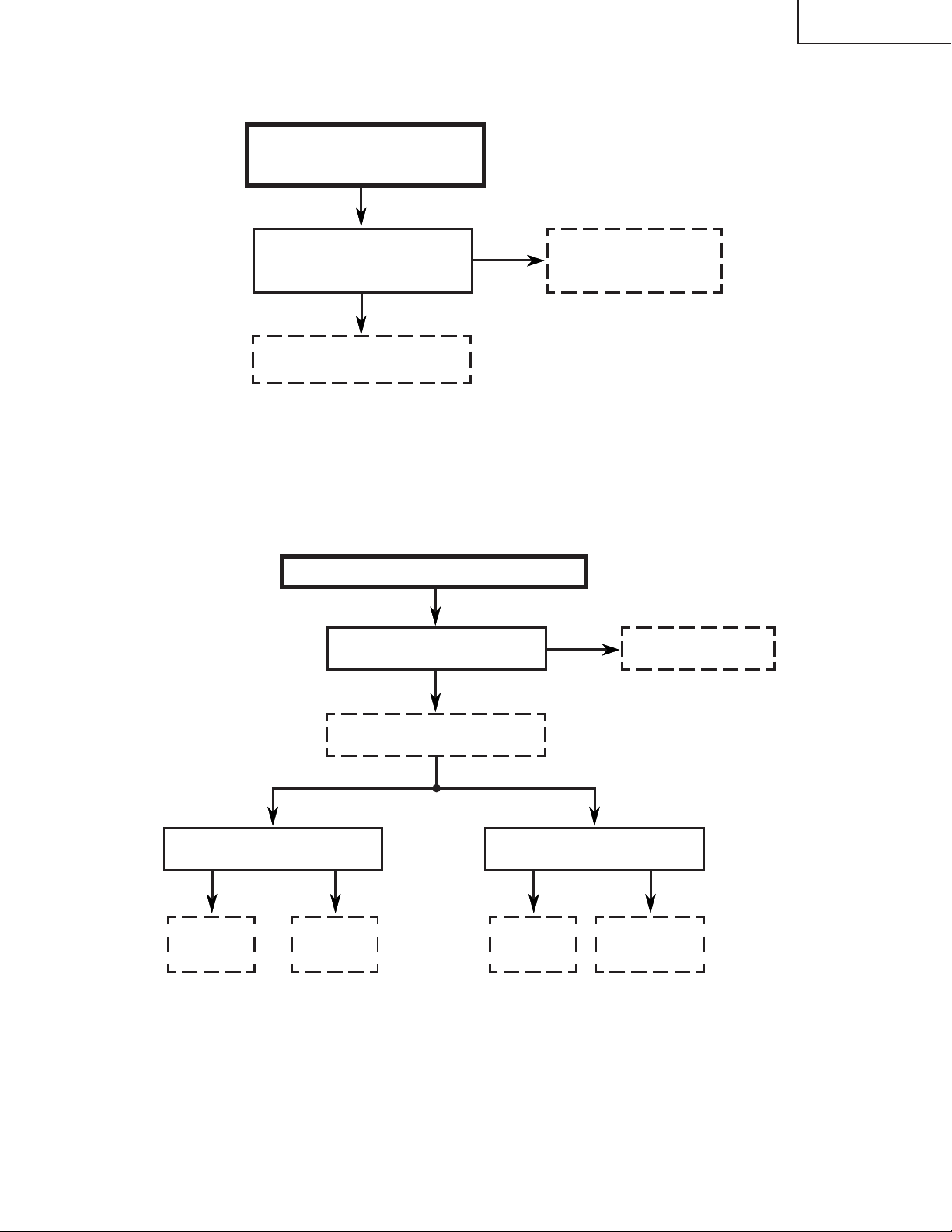
No horizontal sync
Is there horizontal drive signal output
at pin (56) of IC801?
Yes
Are video signal at pin (21) or (29) of
IC801 and horizontal drive signal at
pin (58) of IC801 in sync with each
other?
Yes
Is there horizontal sync signal output
at pin (10) of IC503?
Yes
Is there composite sync signal output
at pin (4) of IC504?
Yes
Check IC1603, IC1607, IC1608 and
all located on the control PWB. Check
also their peripheral parts.
No
No
No
No
Check pins (17) and (18)
of IC801, IC501 and their
peripheral circuits.
Check pins (58) and
(59) of IC801 and their
peripheral parts.
Check IC503 and its
peripheral circuits.
IC504 defective.
No vertical sync
Is there vertical sync signal output at
pin (4) of IC801?
Yes
Is there vertical sync signal input at
pin (11) of IC502?
Yes
Is there vertical sync signal output at
pin (10) of IC502?
Yes
Check IC1606 and its peripheral
parts.
26
No
No
No
Check IC801 and its
peripheral circuits.
Check Q827.
Check IC502 and its
peripheral parts.
Page 27
TROUBLE SHOOTING TABLE (Continued)
Checking the IC1501
interface circuit
XV-C100A/M/E
Are there video signal outputs at pins
(32), (34) and (36) of IC1501?
Yes
Check Q1501, Q1502, Q1503,
Q1504, Q1505 and Q1506.
Lamp Failure to Light Up
Remove Q1701. Does F1701 break
down again?
No
No
Check the voltages of all the
IC1501 pins. Check also their
peripheral circuits.
Yes
Power unit in trouble.
No problem with fuse
Is discharging sound heard?
Replace
T1702 or
lamp.
Check trigger
circuit.
Ballast unit in trouble.
No
Fuse blown-out
Do Q1701 and L1701 break down in
the short-circuit mode?
NoYesYes
Replace
Q1701 and
L1701.
Check Q1701,
L1701 and their
peripheral circuits.
27
Page 28
XV-C100A/M/E
Technische Daten
28
Page 29
HINWEIS FÜR DAS WARTUNGSPERSONAL
ACHTUNG: UV-STRAHLUNG
XV-C100A/M/E
Die Lichtquelle im LCD-Projektor, eine MetallHalogen-Lampe, gibt eine geringe UV-Strahlung ab.
DIREKTE BESTRAHLUNG AUF AUGEN
UND HAUT MUSS VERMIEDEN WERDEN.
Zur Gewährleistung der Sicherheit muß folgendes
beachtet werden:
1. Bei Arbeiten am Projektor bei eingeschalteter
Lampe und abgenommenem oberen Gehäuse
muß unbedingt eine Sonnenbrille getragen
werden.
2. Die Lampe darf nicht außerhalb des
Lampengehäuses eingeschaltet werden.
3. Betrieb für länger als 2 Stunden bei
abgenommenem Gehäuse ist nicht zulässig.
Zur Beachtung bei UV-Strahlung
und Mitteldruck-Lampen
1. Vor dem Auswechseln der Lampe muß der
Netzstecker gezogen werden.
2. Vor Durchführung von Wartungsarbeiten muß das
Gerät eine Stunde abkühlen.
3. Die Lampe darf nur gegen eine der gleichen Art
ausgewechselt werden. Typ CLMPF0053DE03,
bemessen für 65V/155W.
4. Die Lampe gibt eine geringe UV-Strahlung ab,
daher muß direkter Augenkontakt vermieden
werden.
5. Die Mitteldruck-Lampe weist ein Explosionsrisiko
auf. Daher müssen die nachstehenden
Installationsanweisungen beachtet werden, und
die Lampe muß vorsichtig behandelt werden.
ËAuswechseln der Lampe
Hinweis:
Da die Lampe während des Betriebs sehr heiß wird,
sollte die Lampe erst ausgewechselt werden, nachdem
das Gerät mindestens eine Stunde ausgeschaltet war,
damit die Lampe ausreichend abkühlen kann.
Beim Installieren der neuen Lampe muß darauf
geachtet werden, die Lampe selbst (Glaskolben)
nicht zu berühren. Vielmehr muß die Lampe am
Reflektor 2 gehalten werden.
[Es darf nur ein Original-Ersatzteil verwendet
werden.]
Lampe
1
2
GEFAHR! — Niemals die Spannungsversorgung
einschalten, ohne daß eine Lampe vorhanden ist,
um elektrische Schläge und Schäden am Gerät zu
vermeiden, da der Stabilisator anfangs hohe
Spannungen erzeugt.
29
Reflektor
Page 30
XV-C100A/M/E
Lage der Bedienelemente
30
Page 31

Fernbedienter Betrieb
XV-C100A/M/E
31
Page 32

XV-C100A/M/E
Abmessungen
32
Page 33

XV-C100A/M/E
ENTFERNEN DER HAUPTKOMPONENTEN
1. Entfernen der Gehäuse
1-1. Die Schraube herausdrehen, dann die Abdeckung des Glühlampengehäuses abnehmen.
1-2. Die beiden Sicherungsschrauben (zwei 4-mm-Schrauben) aus dem Glühlampen-/Gehäusemodul
herausdrehen.
1-3. D en O bjektiv-Schaltregler soweit verstellen, bis das Objektiv fast bis an die Mitte der Objektivöffnung im
vorderen Gehäuse heranreicht.
1-4. Die sechs Schrauben (sechs 3 mm Gewindeschneidschrauben) vom hinteren Gehäuse entfernen.
1-5. Die M3-Blechschraube aus der Zusatzeinheit-Abdeckung herausdrehen.
1-1
Glühlampengehäuse
1-2
Lampen/Käfig-Moduleinheit
Hinteres Gehäuse
1-3
1-6. Die Abdeckung des Luftfilters entfernen.
1-7. Die fünf Schneidschrauben von der Bodenplatte losdrehen.
1-7
Unteres Gehäuse
1-6
Luftfilterabdeckung
1-4
1-5
1-7
33
Page 34

XV-C100A/M/E
Oberes Gehäuse
1-8
1-8. Nun das obere Gehäuse weiter anheben und die Blattschalter-
Steckverbinder (LL) sowie den Flachkable-Steckverbinder (KE) der
Betriebseinheit abtrennen. Damit ist das obere Gehäuse frei.
1-9. Den Steckverbinder (PE) des Wechselstromkabels (das durch das
hintere Gehäuse vom Vorschaltelement verläuft) abtrennen. Das
hintere Gehäuse abnehmen.
1-10. Das Abstandsstück entfernen.
1-11. Die Schrauben von dem Lensenabdeckung losdrehen.
1-12.Den Stecker des Lautsprechers (SP) abziehen, dann die drei
Sicherungsschrauben entfernen. Die Schraube des Massekabels
herausdrehen; danach die Seitenabdeckung abnehmen.
1-10
Hinteres Gehäuse
1-9
(PE)
1-12
(SP)
1-11
Lensenabdeckung
1-12
Seitliche Abdeckung
Einbauverfahren
1. Die Lensenabdeckung und die Seitenabdeckung auf die Bodenplatte einpassen. Die erforderliche Schrauben
festziehen.
2. Das obere Gehäuse auf dem unteren Gehäuse aufsetzen.
3. Die M3-Blechschraube an der Zusatzeinheit-Abdeckung wieder festziehen.
4. Danach das hintere Gehäuse gegen das obere und untere Gehäuse drücken, um diese anzupassen.
5. Die Schrauben am hinteren Gehäuse festziehen. Die vier 3-mm-Blechschräuben und eine M2.5Maschinenschraube benutzen. Niemals Blechschrauben in das M2.5-Schraubenloch eindrehen. Die
Schraubenwindungen Können dadurch zerstört werden.
6. Die Blechschrauben für die Befestigung des oberen und unteren Gehäuses festziehen.
7. Das Glühlampen-/Gehäusemodul einsetzen; danach die beiden 4-mm-Schrauben festziehen.
8. Die Abdeckung des Glühlampengehäuses anbringen und die Schrauben festziehen.
34
Page 35

XV-C100A/M/E
2. Entfernen der gedruckten Leiterplatten-
2-1. Die Netzeinheit, die Ballasteinheit, die Haupteinheit und die in Richtung der entsprechenden Pfeile herausziehen.
Die Steckverbinder abtrennen.
2-2. Die drei Schrauben herausdrehen, die beiden Klebebänder abziehen, dann die Bedienungstasten-Einheit
herausnehmen.
2-3. Die Schrauben von der Ausgangseinheit, Bedienungstasteneinheit sowie Fernbedienungseinheit losdrehen.
Die Steckverbinder trennen.
2-4. Die Tastenabdeckung entfernen.
3. Entfernen der Flüssigkristalldisplay-Moduleinheit
3-1. Die Schraube von der Tafel-Abdeckung entfernen. Die T afel-
Abdeckung herausnehmen.
3-2. Die Flüssigkristalldisplay-Moduleinheit langsam aus ihrer
Position hochziehen.
Bedientasteneinheit
2-2
TafelAbdeckung
3-2
2-3
2-3
3-1
LCDModuleinheit
InfrarotEmpfängereinheit
Steuereinheit
2-1
2-4
Ballasteinheit
2-3
Oberes Gehäuse
2-1
Netzeinheit
Haupteinheit
Signaleinheit
2-3
35
2-1
Untereinheit
Page 36

XV-C100A/M/E
4. Entfernen der Optikmechanismus-Baugruppe
4-1. Die fünf Schrauben von der Optikmechanismus-Baugruppe entfernen. Die Baugruppe vom unteren Gehäuse
abnehmen.
4-2. Die vier Schrauben an der Lufteinlaßführung herausdrehen. Die Lufteinlaßführung vom unteren Gehäuse
abnehmen.
4-3. Die beiden Schrauben vom Kühlgebläse entfernen.
5.Ausbau der Lampe
5-1. Die drei Versenkschrauben von den oberen und
unteren Lampengehäusen losdrehen.
5-2. Die Arretierschraube und die Mutter vom
Lampenanschluß losdrehen.
5-3. Die Lampen-Arretierfeder aus dem Haken unter
dem Lampengehäuse lösen. Nun die Lampen/Spiegeleinheit herausnehmen.
5-2
Lampen-/
Spiegeleinheit
Unteres Lampengehäuse
5-3
4-3
5-2
Lampen/KäfigModuleinheit
Oberes
Lampengehäuse
5-1
5-1
5-1
Optikmechanismus-
Bau gruppe
Untere GehäuseBaugruppe
Kühlgebläse
(Entlüftungsöfnung)
4-2
4-1
Einlaßkanal-Baugruppe
36
Page 37

Optikeinheit
PCAPH1061CESB
Objektivdeckel
Flüssigkristalldisplay
RLCDP0088CEZZ
OPTIKSYSTEM
Polarisator-Eingangsplatte
PFiLW0164CEZZ
PFiLW0202CEZZ
PFiLW0194CEZZ
Ultraviolett-/Infrarotfilter
Wärmesenke
XV-C100A/M/E
PFiLW0200CEZZ
PLNS-0124CEZZ
Projektionsobjektiv
Beugungsgitter
Reinigung der Objektive und Reflektoren
1. Objektivreiniger
• Reinigungsflüssigkeit:
Das Mischverhältnis von Alkohol und Äther entsprechend der
Umgebungstemperatur wählen. Sicherstellen, daß die Flüssigkeit
unmittelbar nach dem Wischen von der Oberfläche der Linsen
verdampft, dieses ist dann das beste Verhältnis. Je mehr Äther
verwendet wird, desto schneller verdampft die Flüssigkeit.
• Methode:
Ein gut gespültes, gebleichtes Baumwolltuch oder im Fachhandel
erhältliches Reinigungspapier verwenden. Das gebleichte
Baumwolltuch mit der Flüssigkeit befeuchten, und die Linse im Tuch
zwischen Daumen und Zeigefinger halten. Die Linse drehen, und
seine Oberfläche von der Mitte nach außen wischen, um Staub zu
entfernen. Darauf achten, die vergütete Oberfläche nicht zu stark zu
reiben.
CLMPF0053DE03
Lampe/Reflektor-Baugruppe
37
Page 38

XV-C100A/M/E
Ë
Kontrolle der Gesamtbetriebsstunder der Lampe
Die folgende Kontrolle wird durchgeführt, wenn die Lampe 1900 Stunden und 2000 Stunden verwendet wurde.
1. Nach 1900 Stunden Verwendung
Beim Einschalten der Spannungsversorgung erscheint "LAMP" für etwa 1 Minute (blinkt gelb) auf der BildschirmAnzeige, und die Lampen-LED leuchtet rot.
Wenn die Betriebszeit von 1900 Stunden während der V erwendung des Geräts erreicht wird, blinkt die Anzeige
"LAMP" gelb auf dem Bildschirm für 1 Minute genau zur Betriebszeit von 1900 Stunden.
Dann wechselt die Lampen-LED von grün zu rot.
2. Nach 2000 Stunden Verwendung
Wenn die Spannungsversorgung eingeschaltet wird, erscheint "LAMP" für 5 Minuten (blinkt rot) auf der BildschirmAnzeige, und die Lampen-LED leuchtet rot. Fünf Minuten danach wird die Spannungsversorgung automatisch
ausgeschaltet und der Betrieb des Geräts unterbrochen. Wird die Betriebszeit von 2000 Stunden während der
Verwendung des Geräts erreicht, blinkt "LAMP" für 5 Minuten rot auf dem Bildschirm genau zur Betriebszeit von
2000 Stunden. Fünf Minuten später wird die Spannungsversorgung automatisch ausgeschaltet und der Betrieb
des Geräts unterbrochen. (Die Lampen-LED leuchtet seit dem Erreichen der Betriebszeit von 1900 Stunden
ständig rot.)
Wenn nach der 2000-Stunden-Betriebszeit zweimal versucht wird, die Spannungsversorgung einzuschalten,
bleibt das Gerät ausgeschaltet.
3. Bei Erreichen der 2000-Stunden-Betriebszeit die folgenden Schritte durchführen.
Die Lampe gegen eine neue auswechseln. Beide Tasten "VOLUME "" und "SELECT/ADJ "" am Gerät gedrückt
halten und dabei den Hauptnetzschalter (an der Rückseite des Geräts) einschalten. Dadurch wird der LampenBetriebsstundenzähler auf null zurückgestellt. Das Gerät einschalten und sicherstellen, daß "0000H" auf der
Zeit-Anzeige angezeigt wird.
4. Anzeige der Gesamtbetriebsstunden der Lampe
Die ST ATUS3-Dateneinstellungen ändern: PICTURE auf 0, BRIGHT auf MAX, COLOR auf MIN, TINT auf MIN
und SHARPNESS auf MAX. Die Tasten SOUND DOWN und ENTER für mindestens 2 Sekunden gedrückt
halten. Dadurch werden die Gesamtbetriebsstunden auf dem Bildschirm angezeigt.
ZEIT
0000H
GESAMTZEIT
0000H
38
Page 39

XV-C100A/M/E
FUNKTION ADJ IN (Eingangseinstellung)
1. Tasten für die Einstellung
An der Neben-Leiterplatte: S2001
Steuertasten: [ENTER], [MENU], [SELECT/ADJ.'], [SELECT/ADJ."], [VOLUME+],
2. Bedienung
S2001 drücken, um den ADJ IN-Modus abzurufen.
Mit den Tasten [SELECT/ADJ. '] und [SELECT/ADJ."] eine Einstellungsgruppe wählen, dann die
Taste [ENTER] drücken.
Erneut mit den Tasten [SELECT/ADJ. '] und [SELECT/ADJ."] ein Einstellungselement wählen, dann
wieder die Taste [ENTER] drücken.
Die Tasten [SELECT/ADJ. '] und [SELECT/ADJ."] dienen außerdem zum Durchführen der
Einstellungen.
Bei jeder Betätigung der Taste [ENTER] am ADJ IN-Bildschirm werden die Einstellungselemente einer
Gruppe nacheinander gewechselt. (Durch Drücken der Taste [VOLUME +] werden die Elemente in
umgekehrter Reihenfolge durchlaufen.)
Wenn die Taste [MENU] key is pressed, gedrückt wird, erscheint die vorherige Gruppe am Bildschirm.
S2001 erneut drücken, um den ADJ IN-Modus zu verlassen.
Gruppe
Einstellung
-selemente
VIDEO 1
H-CENT
P-H-CENT
CONT
BRIGHT
SUB-R
SUB-G
SUB-B
VIDEO 2
SUB-BIAS
R-BIAS
B-BIAS
R-DRIVE
B-DRIVE
TINT
COLOR
P-COLOR
S-COLOR
VIDEO 3
GAMMA1
GAMMA2
AGCADJ
T-BRT
VIDEO 4
C-CONT
C-BRIGHT
C-COLOR
C-TINT
C-H-CENT
C-PH-CENT
SET
HL
N • W
RED
GREEN
BLUE
N • W
Die Einstellgruppe “LINE” wird hier nicht verwendet.
Kein Signal zuführen, wenn die Einstellungsgruppe “N • W” verwendet wird.
LINE
AUTO
OFF TIMER
TEMP1
TEMP2
FACTORY SET4
TEST
TIME1
TIME2
39
Page 40

XV-C100A/M/E
3. Einstellelemente
VIDEO 1
H-CENT Einstellung der Horizontalposition für NTSC
P-H-CENT Einstellung der Horizontalposition für PAL-System
CONT Einstellung des Unterkontrastes
BRIGHT Einstellung der Helligkeit
SUB-R Nicht belegt, auf 0 (null) eingestellt
SUB-G Nicht verwendet, muß 0 (null) sein
SUB-B Nicht verwendet, muß 0 (null) sein
VIDEO 2
SUB-BIAS Einstellung der Unter-Vormagnetisierung
R-BIAS Weißbalance (rot), Einstellung der Vormagnetisierung
B-BIAS Weißbalance (blau), Einstellung der Vormagnetisierung
R-DRIVE Weißbalance (rot), Einstellung der Ansteuerung
B-DRIVE Weißbalance (blau), Einstellung der Ansteuerung
TINT TINT-Einstellung
COLOR Farbpegel-Einstellung
P-COLOR Farbpegel-Einstellung für PAL-System
S-COLOR Farbpegel-Einstellung für SECAM-System
VIDEO 3
GAMMA1 Gamma-Korrektur 1
GAMMA2 Gamma-Korrektur 2
AGC ADJ AGC-Einstellung
T-BRT Chroma-IC-Helligkeitseinstellung
VIDEO 4
C-CONT Kontrasteinstellung für Komponenten-Eingangssignal
C-BRIGHT Helligkeitseinstellung für Komponenten-Eingangssignal
C-COLOR Farbpegel-Einstellung für Komponenten-Eingangssignal
C-TINT Tönungseinstellung für Komponenten-Eingangssignal
C-H-CENT Einstellung der Horizontalposition für Komponenten-Eingangssignal am NTSC-System
C-PH-CENT Einstellung der Horizontalposition für Komponenten-Eingangssignal am PAL-System
SET
HL Einstellung des Temperaturerfassungspegels
N • W (Einfarbige Anzeige)
RED Rot
GREEN Grün
BLUE Blau
N • W Nicht verwendet
TEST
TIME1 Einstellung in 1-Stunden-Schritten für Gesamt-Glühlampen-Timer
TIME2 Einstellung 1899 h - 1999 h - 0 h - 1899 h für Gesamt-Glühlampen-Timer
40
Page 41

FLIESSDIAGRAMM DER EINSTELLUNGEN
–4
S-COLOR
–6
0
SUB-B
P-COLOR
+7
C-PH-CENT
HL
2
XV-C100A/M/E
0
SUB-G
0
SUB-R
–3
BRIGHT
+6
CONT
0
P-H-CENT
64
B-DRIVE
64
R-DRIVE
74
B-BIAS
74
R-BIAS
COLOR
TINT
T-BRT
ADJ
AGC
GAMMA2
–4
–3
–30
0
0
+5
C-H-CENT
+9
C-TINT
+7
C-COLOR
+5
C-BRIGHT
Not used
0000
TIME2
ENTER
H-CENT SUB-R
VIDEO1
H-CENT
MENU
P-H-CENT SUB-G
CONT SUB-B
–3
BRIGHT
64
SUB-BIAS
MENU
ENTER
TINT
COLOR
P-COLOR
S-COLOR
SUB-BIAS
R-BIAS
B-BIAS
VIDEO2
Anwendermodus-
R-DRIVE
Bildschirm
B-DRIVE
ENTER
S2001
ENTER
MENU
VIDEO1 SET
VIDEO2 N • W
ADJ IN
255
GAMMA1
MENU
GAMMA1
GAMMA2
AGC ADJ
VIDEO3
VIDEO3 LINE
VIDEO4 TEST
T-BRT
ENTER
C-PH-CENT
C-CONT
C-BRIGHT
VIDEO4
–4
C-CONT
MENU
C-COLOR
C-TINT
C-H-CENT
41
ENTER
N • W
R G B N • W
MENU
RED
GREEN
BLUE
N • W
LINE
AUTO
OFF TIMER
TEMP1
TEMP2
FACTORY SET 4
ENTER
Nicht belegt
TEST
TIME1
MENU
TIME1
TIME2
0001
Page 42

XV-C100A/M/E
ELEKTRISCHE EINSTELLUNG
Nr. Einstellgegenstand Einstellbedingungen Einstellverfahren
1
NTSCFreilauffrequenz
(R1616)
2
PALFreilauffrequenz
(R1602)
3
NTSCHorizontalzentrierung
(Digital/AnalogWandler)
4
PAL-Horizontalzentrierung
(Digital/AnalogWandler)
1. Das NTSC-Monoskopsignal
empfangen.
2. S801 gedrückt halten.
1. Das P AL-Monoskopsignal empfangen.
2. S801 gedrückt halten.
1. Das NTSC-Monoskopsignal
empfangen.
2. S2001 drücken, um in den Modus ADJ
IN zu schalten, und das folgende
Element wählen.
Gruppe: VIDEO 1
Element: H-CENT
1. Das P AL-Monoskopsignal empfangen.
2. S2001 drücken, um in den Modus ADJ
IN zu schalten, und das folgende
Element wählen.
Gruppe: VIDEO 1
Element: PAL-H-CENT
• R1616 drehen, bis das Bild nach
Spezifikation erscheint.
• R1602 drehen, bis das Bild nach
Spezifikation erscheint.
• Mit den Tasten ' und " die
Nutzflächenüberschreitung rechts
und links gleich einstellen.
Overscan: 91 - 97%
• Mit den Tasten ' und " die
Nutzflächenüberschreitung rechts
und links gleich einstellen.
Overscan: 91 - 97%
5
Kontrast
(Digital/AnalogWandler)
(Gammakorrektur
eingeschaltet)
1. Das 10stufige NTSC-Mustersignal
empfangen.
2. Das Doppelstrahl-Oszilloskop
zwischen Stift (2) von P1401 und GND
anschließen.
3. S2001 drücken, um in den Modus ADJ
IN zu schalten, und das folgende
Element wählen.
Gruppe: VIDEO 2
Element: S-BIAS
4. Mit den Tasten ' und " die
Wellenform auf die richtige Form
einstellen.
5. S2001 noch einmal drücken, um den
ADJ IN-Modus zu aktivieren, dann die
nachfolgende Position wählen.
Gruppe: VIDEO 1
Element: SUB-R, SUB-G, SUB-B
Sicherstellen, daß diese Elemente alle
den Eintrag 0 (null) aufweisen.
6. R861 so einstellen, daß die größte
Verstärkung erhalten wird.
7. Gruppe: VIDEO 1
Element: CONT
• Mit den Tasten ' und " den
Unterschied zwischen dem 10Stufenpegel und dem Austastpegel
auf 6,0 ±0,15 Vs-s einstellen.
10
42
Page 43

Nr. Einstellgegenstand Einstellbedingungen Einstellverfahren
XV-C100A/M/E
6
Automatische
Verstärkungsregelung: R861
(Gammakorrektur
ausgeschaltet)
7
Kontrast (D/AWandler)
(Gammakorrektur
aus)
1. Das 10stufige NTSC-Mustersignal
empfangen.
2. Das Doppelstrahl-Oszilloskop
zwischen Stift (2) von P1401 und GND
anschließen.
3. Den nachfolgenden Gegendstand
wählen.
Gruppe: VIDEO 1
Gegenstand: CONT
1. Das 10stufige NTSC-Mustersignal
empfangen.
2. Das Doppelstrahl-Oszilloskop
zwischen Stift (2) von P1401 und GND
anschließen.
3. S2001 drücken, um in den Modus ADJ
IN zu schalten, und das folgende
Element wählen.
Gruppe: VIDEO 1
Element: BRIGHT
• R861 drehen, so daß die Differenz
zwischen dem 100 % Weißpegel und
dem Austastpegel auf 4,8 ±0,05 Vss
beträgt.
• Mit den Tasten ' und " die
Differenz zwischen dem Pegel der
ersten Stufe und dem 100 %
Weißpegel auf 2,0 ±0,05 Vss
einstellen.
1
10
10
8
KomponentensignalKontrast (DAC)
(Gammakorrektur
aus)
9
KomponentensignalHelligkeit (DAC)
(Gammakorrektur
aus)
1. Ein NTSC-10-Stufen-Testbildsignal
dem Komponentensignal-Anschluß
zuführen.
2. Das Doppelstrahl-Oszilloskop
zwischen Stift (2) von P1401 und GND
anschließen.
3. S2001 drücken, um in den Modus ADJ
IN zu schalten, und das folgende
Element wählen.
Gruppe: VIDEO 4
Element: C-CONT
1. Ein NTSC-10-Stufen-Testbildsignal
dem Komponentensignal-Anschluß
zuführen.
2. Das Doppelstrahl-Oszilloskop
zwischen Stift (2) von P1402 und GND
anschließen.
3. S2001 drücken, um in den Modus ADJ
IN zu schalten, und das folgende
Element wählen.
Gruppe: VIDEO 4
Element: C-BRIGHT
• Mit den Tasten ' und " die
Differenz zwischen dem 100 %
Weißpegel und dem Austastpegel
auf 4,8 ±0,05 einstellen.
10
• Mit den Tasten ' und " die
Differenz zwischen dem Pegel der
ersten Stufe und dem 100 %
Weißpegel auf 2,0 ±0,05 Vss
einstellen.
1
10
43
Page 44

XV-C100A/M/E
Nr.
Einstellgegenstand Einstellbedingungen Einstellverfahren
10
Farbton (Digital/
AnalogWandler)
11
KomponentensignalTönung
(DAC)
1. Das NTSC-Halbfarbbalkensignal
empfangen.
2. S2001 drücken, um in den Modus ADJ
IN zu schalten, und das folgende
Element wählen.
Gruppe: VIDEO 2
Element: TINT
3. Das Doppelstrahl-Oszilloskop
zwischen Stift (5) von P803 und GND
anschließen.
1. Ein NTSC-Halbfarbbalkensignal dem
Komponentensignal-Anschluß
zuführen.
2. S2001 drücken, um in den Modus ADJ
IN zu schalten, und das folgende
Element wählen.
Gruppe: VIDEO 4
Element: C-TINT
3. Das Doppelstrahl-Oszilloskop
zwischen Stift (3) von P803 und GND
anschließen.
• Mit den Tasten ' und " die
Signalwellenform (B-Y) auf eine
gerade Abwärtsflanke einstellen.
• Mit den Tasten ' und " die
Signalwellenform (B-Y) auf eine
gerade Abwärtsflanke einstellen.
12
UnterVormagnetisierung (Digital/
AnalogWandler)
(Gammakorrektur
eingeschaltet)
13
R-Ansteuerung
B-Ansteuerung
1. Das 10stufige NTSC-Mustersignal
empfangen.
2. Das Doppelstrahl-Oszilloskop
zwischen Stift (2) von P1401 und GND
anschließen.
3. S2001 drücken, um in den Modus ADJ
IN zu schalten, und das folgende
Element wählen.
Gruppe: VIDEO 2
Element: SUB-BIAS
1. Das 10stufige NTSC-Mustersignal
empfangen.
2. Ein Doppelstrahl-Oszilloskop zwischen
Stift (3) (R) [oder Stift (1) (B)] von
P1401 und der Masse (GND)
anschließen.
3. S2001 drücken, um in den Modus ADJ
IN zu schalten, und das folgende
Element wählen.
Gruppe: VIDEO 2
Element: R-DRIVE, B-DRIVE
• Mit den Tasten ' und " die
Differenz zwischen den Weißpegeln
auf 3,0 ±0,05 Vss einstellen.
• Mit den Tasten ' und " die
Differenz zwischen dem Pegel der
ersten Stufe und dem Weißpegel
auf 2,0 ±0,05 Vss einstellen.
44
Page 45

Nr. Einstellgegenstand Einstellbedingungen Einstellverfahren
XV-C100A/M/E
14 • Mit den Tasten ' und " die
R-Vormagnetisierung
B-Vormagnetisierung
15
NTSC-Farbe
(Digital/AnalogWandler)
(Gammakorrektur
eingeschaltet)
1. Das 10stufige NTSC-Mustersignal
empfangen.
2. Ein Doppelstrahl-Oszilloskop zwischen
Stift (3) (R) [oder Stift (1) (B)] von
P1401 und der Masse (GND)
anschließen.
3. S2001 drücken, um in den Modus ADJ
IN zu schalten, und das folgende
Element wählen.
Gruppe: VIDEO 2
Element: R-BIAS, B-BIAS
1. Das NTSC-Halbfarbbalkensignal
empfangen.
2. Das Doppelstrahl-Oszilloskop
zwischen Stift (3) von P1401 und GND
anschließen.
3. S2001 drücken, um in den Modus ADJ
IN zu schalten, und das folgende
Element wählen.
Gruppe: VIDEO 2
Element: COLOR
Differenz zwischen den Weißpegeln
auf 3.0 ±0,05 Vss einstellen.
• Mit den Tasten ' und " die
Differenz zwischen dem 100 %
Weißpegel und dem Rotpegel auf
0±0,05 Vss einstellen.
100 % weiß
Primärrot
16
PAL-Farbe
(Digital/AnalogWandler)
(Gammakorrektur
eingeschaltet)
1. Das PAL-Halbfarbbalkensignal
empfangen.
2. Das Doppelstrahl-Oszilloskop
zwischen Stift (3) von P1401 und GND
anschließen.
3. S2001 drücken, um in den Modus ADJ
IN zu schalten, und das folgende
Element wählen.
Gruppe: VIDEO 2
Element: P-COLOR
45
• Mit den Tasten ' und " die
Differenz zwischen dem 100 %
Weißpegel und dem Rotpegel auf
0,10 ±0,05 Vss einstellen.
100 % weiß
Primärrot
Page 46

XV-C100A/M/E
Nr. Einstellgegenstand Einstellbedingungen Einstellverfahren
17
SECAM-Farbe
(Digital/AnalogWandler)
(Gammakorrektur
eingeschaltet)
18
Farbe des
Komponentensignals (DAC)
1. Das SECAM-Halbfarbbalkensignal
empfangen.
2. Das Doppelstrahl-Oszilloskop
zwischen Stift (3) von P1401 und GND
anschließen.
3. S2001 drücken, um in den Modus ADJ
IN zu schalten, und das folgende
Element wählen.
Gruppe: VIDEO 2
Element: S-COLOR
1. Ein NTSC-Halbfarbbalkensignal dem
Komponentensignal-Anschluß
zuführen.
2. S2001 drücken, um in den Modus ADJ
IN zu schalten, und das folgende
Element wählen.
Gruppe: VIDEO 4
Element: C-COLOR
• Mit den Tasten ' und " die
Differenz zwischen dem 100 %
Weißpegel und dem Rotpegel auf
0,10 ±0,05 Vss einstellen.
100 % weiß
• Sich vergewissern, daß der Wert auf
“12” gesetzt ist.
Primärrot
19
GegenVormagnetisierung (R1402)
20
Weißbalance
(DAC)
1. Das NTSC-Monoskopsignal
empfangen.
1. Das NTSC-Monoskopsignal
empfangen.
2. S2001 drücken, um in den Modus ADJ
IN zu schalten, und das folgende
Element wählen.
Gruppe: VIDEO 2
Element: R-BIAS, B-BIAS
• R1402 so drehen, daß der beste
Kontrast erhalten wird.
• Unter Verwendung der ' und "
T asten den W eißabgleich visuell auf
die optimale Position einstellen.
46
Page 47

Nr. Einstellgegenstand Einstellbedingungen Einstellverfahren
XV-C100A/M/E
21
Prüfung der
Bildschirmanzeigeposition
(L2003)
22
Überprüfung der
T emperatursensorEinstellung
1. Das NTSC-Monoskopsignal
empfangen.
2. Die Tasten SOUND UP/DOWN
drücken, um den Lautstärkebalken auf
den Bildschirm zu rufen.
1. S2001 drücken, um in den Modus ADJ
IN zu schalten, und die folgende
Gruppe wählen.
Gruppe: SET
Element: HL
• L2003 drehen, so daß der Balken
gut auf dem Bildschirm zentriert ist.
• Sich vergewissern, daß der Wert auf
“2” gesetzt ist.
23
Horizontale Mitte
des
Komponentensignals (NTSC)
(DAC)
24
Horizontale Mitte
des
Komponentensignals (PAL)
(DAC)
1. Das NTSC-Testbildsignal zuführen.
2. S2001 drücken, um den ADJ IN-Modus
zu aktivieren, dann die folgende
Position wählen.
Gruppe: VIDEO 4
Element: C-H-CENT
1. Das PAL-Testbildsignal zuführen.
2. S2001 drücken, um den ADJ IN-Modus
zu aktivieren, dann die folgende
Position wählen.
Gruppe: VIDEO 4
Element: C-PH-CENT
• Unter Verwendung der ' und "
T asten den Abtastbereich rechts und
links auf die genau gleiche Distanz
einstellen.
Abtastbereich: 91 - 97%
• Unter Verwendung der ' und "
T asten den Abtastbereich rechts und
links auf die genau gleiche Distanz
einstellen.
Abtastbereich: 91 - 97%
47
Page 48

XV-C100A/M/E
TABELLE FÜR STÖRUNGSSUCHE
Prüfung des Videosystems
Kein Bild
Das Netzteil prüfen.
IC401, DL401 und ihre
Peripheriekreise prüfen.
Nein
Nein
Leuchtet die Lampe?
Ja
Liegt Spannung an den
Steckverbindern EA und EV an?
Ja
Liegt ein Signal an den Stiften
(21) und (29) von IC801 an?
Ja
Liegt ein Signal an den Stiften (1), (2)
und (3) von P803 an?
Ja
Mit “Prüfung des IC1501
Schnittstellenkreises” weitermachen.
Nein
Die Lampe prüfen.
Den Stromkreis des
Vorschaltelements prüfen.
Nein
IC801, Q801, Q804, Q802, Q803
und ihre Peripheriekreise prüfen.
Keine Farbe oder schlechter
Farbton bei NTSC-Signal
Liegt ein Chromasignaleingang an
Stift (20) von IC801 an?
Ja
IC801, IC801, IC804 und seine
Peripheriekreise prüfen
(insbesondere X801 und C810).
48
Nein
DL401, IC401, Q401 und ihre
Peripheriekreise prüfen.
Page 49

TABELLE FÜR STÖRUNGSSUCHE (fortgesetzt)
Keine Farbe oder
schlechter Farbton bei
PAL-Signal
XV-C100A/M/E
Liegt ein Videosignaleingang an Stift
(29) von IC801 an?
Ja
Werden die Signale R-Y und B-Y an
den Stiften (45) und (46) von IC801
ausgegeben?
IC802, IC804 und seine
Peripheriekreise prüfen.
Keine Farbe oder
schlechter Farbton bei
SECAM-Signal
Liegt ein Chromasignaleingang an
Stift (20) von IC803 an?
Nein
Nein
Nein
IC401 und seine
Peripheriekreise prüfen.
IC801 und seine
Peripheriekreise prüfen
(insbesondere X801 und C811).
IC401 und seine Peripheriekreise
prüfen.
Ja
Liegen an den Stiften (11) und (12)
von IC803 R-Y- und
B-Y-Ausgangssignale an?
Ja
Wird Spannung von über 4 V an Stift
(49) von IC801 zugeführt?
Ja
IC801, IC802, IC804 und seine
Peripheriekreise prüfen.
Nein
Nein
IC803 und seine Peripheriekreise
prüfen.
IC803 und seine Peripheriekreise
prüfen.
49
Page 50

XV-C100A/M/E
Kein KomponentensignalBild
TABELLE FÜR STÖRUNGSSUCHE (fortgesetzt)
Liegt an Stift (35) von IC3003 ein
Y-Eingangssignal an?
Ja
Liegen an den Stiften (13) und (14)
von IC3003 Eingangssignale an?
Ja
Liegen an den Stiften (44), (45) und
(46) von IC3003 Ausgangssignale
an?
Ja
Liegen an den Stiften (35), (36) und
(37) von IC801 Eingangssignale an?
Ja
IC801 und die
Peripherie-Schaltkreise überprüfen.
Nein
Nein
Nein
Nein
Q3001, Q3020, Q3021 und
die Peripherie-Schaltkreise
überprüfen.
IC2001 und die
Peripherie-Schaltkreise
überprüfen.
IC3003 und die
Peripherie-Schaltkreise
überprüfen.
C830, C831 und C832 sowie
die Peripherie-Schaltkreise
überprüfen.
Den Schnittstellen-Schaltkreis von
IC1501 überprüfen.
Keine KomponentensignalFarbe
Liegen an den Stiften (33) und (34)
von IC3003 Eingangssignale an?
Ja
IC3003 und die
Peripherie-Schaltkreise überprüfen.
Nein
Q3006 bis Q3013 sowie
Q3007 bis Q3010 überprüfen.
50
Page 51

TABELLE FÜR STÖRUNGSSUCHE (fortgesetzt)
Keine horizontale
Synchronisierung
Ja
XV-C100A/M/E
Liegt ein horizontaler
Ansteuerungssignalausgang an Stift
(56) von IC801 an?
Ja
Sind das Videosignal an Stift (21)
oder (29) von IC801 und das
horizontale Ansteuerungssignal an
Stift (58) von IC801 miteinander
synchronisiert?
Ja
Liegt ein horizontaler
Synchronisierungssignalausgang an
Stift (10) von IC503 an?
Ja
Liegt ein BASSynchronisierungssignalausgang an
Stift (4) von IC504 an?
Ja
IC1603, IC1607 und IC1608, die alle
auf der Steuerung-Leiterplatte
angeordnet sind, prüfen. Außerdem
ihre Peripherieteile prüfen.
Nein
Nein
Nein
Nein
Die Stifte (17) und (18)
von IC801, IC501 und die
Peripherie-Schaltkreise
überprüfen.
Stifte (58) und (59)
von IC801 und ihre
Peripherieteile prüfen.
IC503 und seine
Peripheriekreise prüfen.
IC504 defekt.
Keine vertikale
Synchronisierung
Ja
Liegt ein vertikaler
Synchronisierungssignalausgang an
Stift (4) von IC801 an?
Ja
Liegt ein vertikaler
Synchronisierungssignaleingang an
Stift (11) von IC502 an?
Ja
Liegt ein vertikaler
Synchronisierungssignalausgang an
Stift (10) von IC502 an?
Ja
IC1606 und seine Peripherieteile
prüfen.
Nein
Nein
Nein
IC801 und seine
Peripheriekreise prüfen.
Q804 und Q805 prüfen.
IC502 und seine
Peripherieteile prüfen.
51
Page 52

XV-C100A/M/E
TABELLE FÜR STÖRUNGSSUCHE (fortgesetzt)
Prüfung des IC1501
Schnittstellenkreises
Ja
Liegen Videosignalausgänge an den
Stiften (32), (34) und (36) von IC1501
an?
Ja
Q1501, Q1502, Q1503, Q1504,
Q1505 und Q1506 prüfen.
Lampe leuchtet nicht
Q1701 entfernen. Fällt F1701 wieder
aus?
Nein
Nein
Die Spannungen aller Stifte
von IC1501 prüfen.
Außerdem ihre
Peripheriekreise prüfen.
Ja
Problem bei
Spannungseinheit.
Sicherung in Ordnung
Wird Entladungston gehört?
T1702 oder
Lampe
ersetzen.
Triggerschaltkreis
überprüfen.
Problem bei Vorschalteinheit
NeinJa
Sicherung durchgebrannt
Fallen Q1701 und L1701 im
Kurzschlußmodus aus?
Ja
Q1701 und
L1701
ersetzen.
Q1701, L1701 und ihre
Peripherieschaltkreise
überprüfen.
Nein
52
Page 53

XV-C100A/M/E
53
Page 54

XV-C100A/M/E
!"#$%
!"#$%&
!"#$%&'()*+,-./01
!"#$%&'
!"#$%
!
!"# !"#$%&'=
NK !"#$%&'()*+,-.*/
! !
!"
OK !"#$%&'(()*+,
PK !"#$%&'()*+,- O
!"#$%&
!"
NK !"#$ !"#$%&
OK !"#$%& !"#$%&'
PK !"#$%&'()*
`ijmcMMRPabMP SRsLNRRt
QK !"#$%&'()*+,-
!"#
RK !"#$%&'() !
!"#$%&'()*
Ë
== !"#$%
!"#$%&'()* !"
!"#$%&'()* !"#$
!"#$% !"#$%&'2
! !"#$%&'(
!"#$%&'()*+
1
2
!" !"#$% !"#
!"#$% !"#$%&'()
!"#$
!"#$%&'(
54
Page 55

!"#$
XV-C100A/M/E
55
Page 56

XV-C100A/M/E
!"#$%
56
Page 57

!
XV-C100A/M/E
57
Page 58

XV-C100A/M/E
1-4
1-5
!"#$
1-1
1-2
1-7
1-3
1-6
1-7
58
Page 59

1-8
XV-C100A/M/E
1-10
1-9
(PE)
1-11
1-12
(SP)
1-12
59
Page 60

XV-C100A/M/E
2-2
2-3
3-2
3-1
2-3
2-1
2-4
2-1
2-3
2-3
60
2-1
Page 61

XV-C100A/M/E
5-2
4-3
5-3
5-2
5-1
5-1
5-1
4-1
4-2
61
Page 62

XV-C100A/M/E
!
!
PFiLW0164CEZZ
PFiLW0202CEZZ
RLCDP0088CEZZ
PCAPH1061CESB
PLNS-0124CEZZ
PFiLW0200CEZZ
PFiLW0194CEZZ
CLMPF0053DE03
Ë
!"#$%
62
Page 63

Ë
XV-C100A/M/E
0000H
0000H
63
Page 64

XV-C100A/M/E
!"#$%& '()LINE。
!"#N·W !"#$%
64
Page 65

XV-C100A/M/E
65
Page 66

XV-C100A/M/E
0
SUB-B
!"#
–4
S-COLOR
–6
P-COLOR
+7
C-PH-CENT
HL
2
0
SUB-G
0
SUB-R
–3
BRIGHT
+6
CONT
0
P-H-CENT
64
B-DRIVE
64
R-DRIVE
74
B-BIAS
74
R-BIAS
COLOR
TINT
T-BRT
ADJ
AGC
GAMMA2
–30
0
0
–4
+5
C-H-CENT
–3
+9
C-TINT
+7
C-COLOR
+5
C-BRIGHT
0000
TIME2
ENTER
H-CENT SUB-R
VIDEO1
H-CENT
MENU
P-H-CENT SUB-G
CONT SUB-B
–3
BRIGHT
ENTER
TINT
SUB-BIAS
VIDEO2
SUB-BIAS
MENU
COLOR
P-COLOR
R-BIAS
B-BIAS
64
S-COLOR
R-DRIVE
B-DRIVE
S2001
ENTER
ENTER
MENU
VIDEO1 SET
VIDEO2 N • W
ADJ IN
255
GAMMA1
MENU
GAMMA1
GAMMA2
AGC ADJ
VIDEO3
VIDEO3 LINE
VIDEO4 TEST
T-BRT
ENTER
C-PH-CENT
C-CONT
C-BRIGHT
VIDEO4
–4
C-CONT
MENU
C-COLOR
C-TINT
C-H-CENT
66
ENTER
N • W
RED
R G B N • W
MENU
GREEN
BLUE
N • W
LINE
AUTO
OFF TIMER
TEMP1
TEMP2
ENTER
FACTORY SET 4
TEST
TIME1
MENU
TIME1
TIME2
0001
Page 67

!
XV-C100A/M/E
67
10
Page 68

XV-C100A/M/E
10
10
1
10
68
10
1
Page 69

XV-C100A/M/E
69
Page 70

XV-C100A/M/E
70
Page 71

XV-C100A/M/E
71
Page 72

XV-C100A/M/E
!"#$kqp`
!a^`
!"#Em^i
FEa^`F
1. kqp` !"#$%&'
2. pOMMN !"^ag=fk
!"#$%&'()
・ !sfablQ
・ !`JeJ`bkq
1. m^i !"#$%&'
2. pOMMN !"^ag=fk
!"#$%&'()
・ !sfablQ
・ !`JmeJ`bkq
・'
!"
!VNVT
・'
!"
!VNVT
"
"
!"#$%&'(
!"#$%&'(
72
Page 73

!"
XV-C100A/M/E
73
Page 74

XV-C100A/M/E
!"#$%&'
74
Page 75

!"#$%&'
XV-C100A/M/E
75
Page 76

XV-C100A/M/E
!"#$%&'
76
Page 77

!"#$%&'
XV-C100A/M/E
77
Page 78

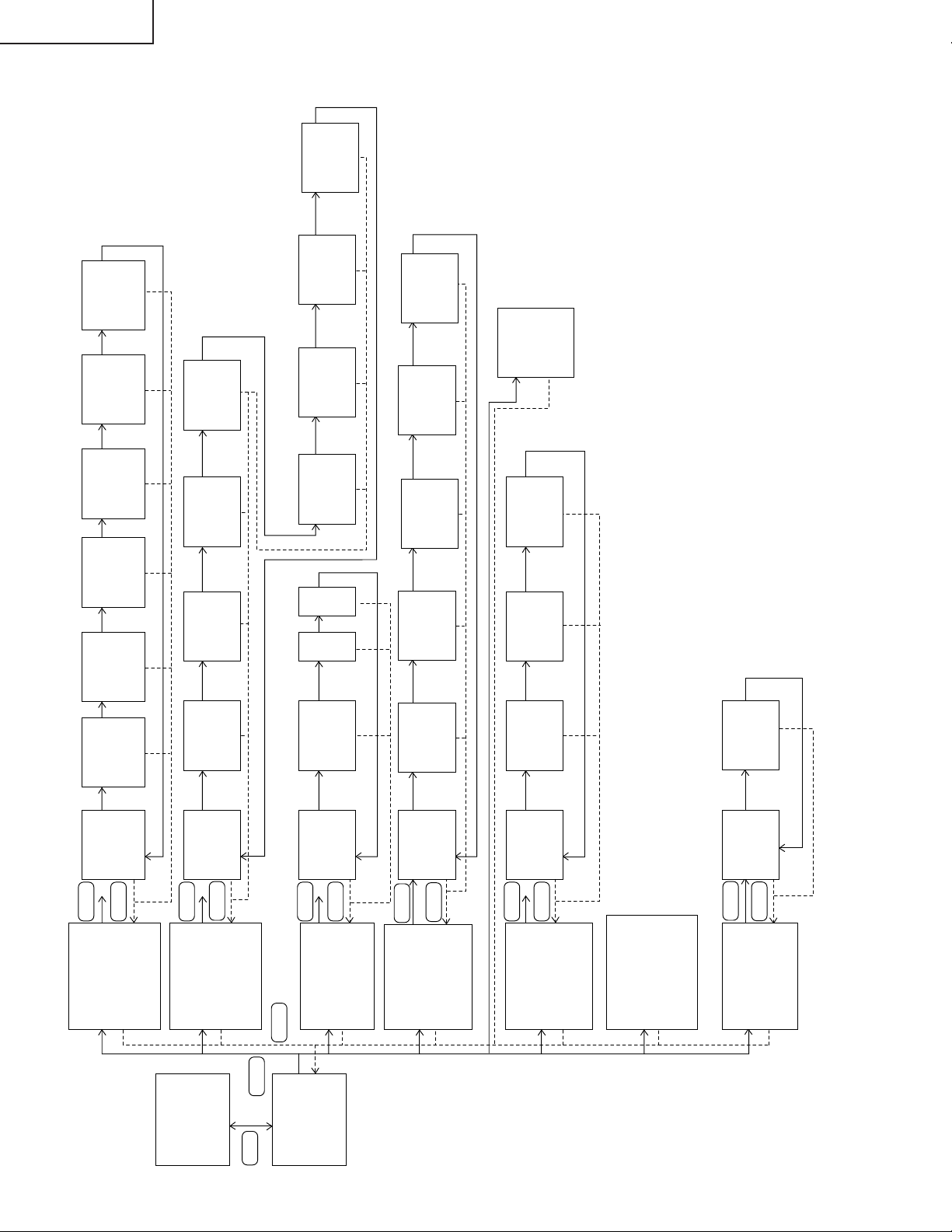
CHASSIS LAYOUT / CHASSIS-ANORDNUNG
!"#$%
H
R/C UNIT
DUNTK9004WEV0/V1/V4
G
F
BALLAST UNIT
RDENC0265CEZZ/DUNTKA009WEV0
RDENC0262CEZZ/DUNTKA009WEV1
XV-C100A/M/E
POWER UNIT
RDENC0266CEZZ/DUNTKA001WEV2
CONTROL UNIT
DUNTK9003WEV0/V1/V4
E
D
C
MAIN UNIT
DUNTK9001WEV0/V1/V4
SUB UNIT
DUNTK9002WEV0/V1/V4
B
OPERATION KEY UNIT
RUNTK0624CEZZ
A
121110987654321
78
79
Page 79

OVERALL WIRING DIAGRAM / GESAMTSCHALTPLAN
!"#$
H
G
F
XV-C100A/M/E
E
D
C
B
A
121110987654321
80
81
Page 80

XV-C100A/M/E
DESCRIPTION OF SCHEMATIC DIAGRAM
VOLTAGE MEASUREMENT CONDITION:
1. Voltages at test points are measured at the supply voltage of AC 220V. Signals
are fed by a colour bar signal generator for servicing purpose and the above
voltages are measured with a 20k ohm/V tester.
H
WAVEFORM MEASUREMENT CONDITION:
1. Waveforms at test points are observed at the supply voltage of AC 220V.
Signals are fed by a colour bar signal generator for servicing purpose.
INDICATION OF RESISTOR & CAPACITOR:
RESISTOR
1. The unit of resistance “Ω” is omitted.
(K=kΩ=1000 Ω, M=MΩ).
2. All resistors are ± 5%, unless otherwise noted.
(J= ± 5%, F= ± 1%, D= ± 0.5%)
3. All resistors are 1/16W, unless otherwise noted.
4. All resistors are Carbon type, unless otherwise noted.
C : Solid W : Cement
S : Oxide Film T : Special
N : Metal Coating
G
F
BESCHREIBUNG DES SCHEMATISCHEN SCHALTPLANS
SPANNUNGSMESSUNGEN:
1. Spannungen an den Prüfpunkten werden bei einer Netzspannung von 220V
gemessen, Signale werden für die Wartung mit einem Farbbalken-Signal
generator zugeführt, und Spannungen werden mit einem Meßinstrument
(20 kΩ/V) ermittelt.
SIGNALFORMMESSUNGEN:
1. Die Wellenformen an den Testpunkten werden bei einer Netzspannung von
220V verfolgt. Signale werden für die Wartung mit einem Farbbalken-Signal
generator zugeführt.
BEZEICHNUNG DES WIDERSTANDS UND
KONDENSATORS:
WIDERSTAND
1. Die Widerstandseinheit “Ω” wird weggelassen.
(K=kΩ=1000 Ω, M=MΩ).
2. Alle Widerstände haben ± 5%, sofern nicht anders angegeben.
(J= ± 5%, F= ± 1%, D= ± 0.5%)
3. Alle Widerstände haben 1/16W, sofern nicht anders angegeben.
4. Alle Widerstände sind Kohletyp, sofern nicht anders angegeben.
C : Fest W : Zement
S : Oxidfilm T : Spezial
N : Metallüberzug
E
D
C
!"#$%
CAPACITOR
1. All capacitors are µF, unless otherwise noted.
(P=pF=µµF).
2. All capacitors are 50V, unless otherwise noted.
3. All capacitors are Ceramic type, unless otherwise noted.
(ML): Mylar (TA): Tantalum
(PF): Polypro Film (ST): Styrol
CAUTION:
This circuit diagram is original one, therefore there may be a slight difference from yours.
SAFETY NOTES:
1. DISCONNECT THE AC PLUG FROM THE AC OUTLET BEFORE
REPLACEING PARTS.
2. SEMICONDUCTOR HEAT SINKS SHOULD BE REGARDED AS
POTENTIAL SHOCK HAZARDS WHEN THE CHASSIS IS OPERATING.
IMPORTANT SAFETY NOTICE:
PAR TS MARKED WITH “å” ( )ARE IMPORT ANT FOR MAINT AINING
THE SAFETY OF THE SET. BE SURE TO REPLACE THESE PARTS WITH
SPECIFIED ONES FOR MAINTAINING THE SAFETY AND PERFORMANCE
OF THE SET.
KONDENSATOR
1. Die Kapazitätseinheit ist µF, sofern nicht anders angegeben.
(P=pF=µµF).
2. Alle Kondensatoren haben 50V, sofern nicht anders angegeben.
3. Alle Kondensatoren sind Keramiktyp, sofern nicht anders angegeben.
(ML): Mylar (TA): Tantal
(PF): Polyprofilm (ST): Styrol
ACHTUNG:
bei diesem Schaltplan handelt es sich um den ursprünglichen. Esönnen
daher geringfügige Unterschiede zu dem lhrem bestehen.
SICHERHEITSANMERKUNGEN:
1. VOR DEM AUSWECHSELN VON TEILEN MUSS UNBEDINGT
NETZSTECKER AUS DER NETZSTECKDOSE GEZOGEN WERDEN.
2. DIE WARMEABLEITER DER HALBLEITER SOLLTEN BEIM BETRIEB
DES CHASSIS ALS MÖGLICHE URSACHEN VON GEFÄHRLICHEN
ELEKTRISCHEN SCHLÄGEN BETRACHTET WERDEN.
WICHTIGE SICHERHEITSANMERKUNGEN:
MIT “å”( )BEZEICHNETEN TEILE SIND BESONDERS WICHTIG
FÜR DIE AUFRECHTERHALTUNG DER SICHERHEIT . BEIM WECHDIESER
TEILE SOLLTEN DIE VORGESCHRIEBENEN TEILE IMMER VERWENDET
WERDEN, UM SOWOHL DIE SICHERHEIT ALS AUCH DIE LEISTUNG DES
GERÄTES AUFRECHTZUERHALTEN.
1 IC801 pin 4
1V/div, 5msec/div
5 IC801 pin 58
0.2V/div, 20µsec/div
9 IC502 pin 10
1V/div, 5msec/div
e P803 pin 2
0.2V/div, 20µsec/div
WAVEFORMS / WELLENFORMEN
2 IC801 pin 20
0.1V/div, 20µsec/div
6 IC801 pin 45
0.2V/div, 20µsec/div
0 IC502 pin 11
1V/div, 5msec/div
r P803 pin 3
0.2V/div, 20µsec/div
3 IC801 pin 21
0.2V/div, 20µsec/div
7 IC801 pin 46
0.2V/div, 20µsec/div
q IC504 pin 4
1V/div, 5msec/div
t P803 pin 5
0.5V/div, 20µsec/div
4 IC801 pin 29
0.2V/div, 20µsec/div
8 IC803 pin 20
50mV/div, 20µsec/div
w P803 pin 1
0.2V/div, 20µsec/div
y IC1501 pin 32
2V/div, 20µsec/div
!"#$
1. !"#$%&'(AC220V !"#$%&'()*+,
!"#$%&'(& )*+,-./0120 /
!"
!"#$
1. !"#$%&'AC220V !"#$%&'()*+,-
!"#$%&'%(
B
!"#$%&
1. !"#$%&'()*+
(Kk1000M )
2. !"#$%&'()*+,5
(J5F1D0.5)
3. !"#$%&'()*+,-1/16W
4. !"#$%&'()*+,-.
` !" t !"
p !"# q !"
k !"#$
A
1. !"#$%&'()*+,-./0(µF)
(P µµF)
2. !"#$%&'()*+,50
3. !"#$%&'()*+,-./0
(ML) !"#$% (TA) !"#
(PF) !"#$%& (ST) !"#$%
!"#$%&'()*+#$%,-. /0 !"#$%12
!"#
!"#$%&
1. !"#$%&'()*+,-./0
2. !"#$%&'()*+,-./01234$56789
!"#$%&
å ( ) !"#$%&'()*+,-./
!"#$%&'()*$%+,-./012*3456789
!"
82
u IC1501 pin 34
2V/div, 20µsec/div
a P1401 pin 3
2V/div, 20µsec/div
i IC1501 pin 36
2V/div, 20µsec/div
o P1401 pin 1
83
2V/div, 20µsec/div
p P1401 pin 2
2V/div, 20µsec/div
121110987654321
Page 81

XV-C100A/M/E
Ë
MAIN UNIT-1/3 / HAUPT-EINHEIT-1/3
H
G
F
!" JNLP
E
D
C
B
A
121110987654321
84
85
Page 82

XV-C100A/M/E
Ë
MAIN UNIT-2/3 / HAUPT-EINHEIT-2/3
H
G
F
!" JOLP
E
D
C
B
A
121110987654321
86
87
Page 83

XV-C100A/M/E
Ë
MAIN UNIT-3/3 / HAUPT-EINHEIT-3/3
H
G
F
!" JPLP
E
D
C
B
A
121110987654321
88
89
Page 84

XV-C100A/M/E
Ë
SUB and INFRARED R/C RECEIVER UNIT / UNTER und
INFRAROT-EMPFÄNGEREINHEIT
H
G
F
!"#$%&'()*+,-.
E
D
C
B
A
121110987654321
90
91
Page 85

XV-C100A/M/E
Ë
CONTROL UNIT / STEUERWERKEINHEIT
H
G
F
!"
E
D
C
B
A
121110987654321
92
93
Page 86

XV-C100A/M/E
Ë
POWER UNIT / NETZEINHEIT
H
!"=
(XV-C100M/E)
RDENC0266CEZZ (OLD)
G
F
E
D
C
B
A
121110987654321
94
95
Page 87

XV-C100A/M/E
Ë
POWER UNIT / NETZEINHEIT
H
G
F
!"
(NEW)
E
D
C
B
A
121110987654321
96
97
Page 88

XV-C100A/M/E
Ë
BALLAST UNIT / BALLASTEINHEIT
H
G
F
RDENC0265CEZZ (OLD)
!"#=
(XV-C100M)
E
D
C
B
A
121110987654321
98
99
Page 89

XV-C100A/M/E
Ë
BALLAST UNIT / BALLASTEINHEIT
H
G
F
RDENC0262CEZZ (OLD)
!"#=
(XV-C100E)
E
D
C
B
A
121110987654321
100
101
Page 90

XV-C100A/M/E
Ë
BALLAST UNIT / BALLASTEINHEIT
H
G
F
!"#=
(NEW)
(XV-C100A/M)
E
D
C
B
A
121110987654321
102
103
Page 91

XV-C100A/M/E
Ë
BALLAST UNIT / BALLASTEINHEIT
H
G
F
!"#=
(NEW)
(XV-C100E)
E
D
C
B
A
121110987654321
104
105
Page 92

XV-C100A/M/E
Ë
OPERATION KEY UNIT / BEDIENTASTENEINHEIT
H
H
G
G
F
F
!"
E
E
D
D
C
C
B
B
A
A
87109654321
654321
106
Page 93

Ë
PRINTED WIRING BOARD ASSEMBLIES /
XV-C100A/M/E
LEITERPLATTENINHEITIN
H
G
F
E
!"#$
Operation Key Unit (Wiring Side) /
Bedienungstasteneinheit
(Leiterbahnseite)
!"#$%&'()&*"+,
D
C
Control Unit (Wiring Side) /
Steuerwerkeinheit (Leiterbahnseite)
!"#$%&'$()*+
B
Operation Key Unit (Component Side) /
Bedienungstasteneinheit
(Bestückungsseite)
!"#$%&'()*!+,-
Infrared R/C Receiver Unit
(Wiring Side) /
Infrarot-empfängereinheit
(Leiterbahnseite)
!"#$%&'()*+,- +./01
A
Control Unit (Component Side) /
Steuerwerkeinheit (Bestückungsseite)
!"#$%&'()*+,
107
Infrared R/C Receiver Unit
(Component Side) /
Infrarot-empfängereinheit
(Bestückungsseite)
!"#$%&'()*+,-./0123
1716 1918151413121110
654321
Page 94

XV-C100A/M/E
H
G
F
E
Main Unit (Wiring Side) /
Haupteinheit (Leiterbahnseite)
!"#$!%&'(
D
C
B
A
Sub Unit (Wiring Side) /
Untereinheit (Leiterbahnseite)
!"#$%&'(%)!*+
87109654321
108
Page 95

XV-C100A/M/E
Main Unit (Component Side) /
Haupteinheit (Bestückungsseite)
!"#$%&'()
Sub Unit (Component Side) /
Untereinheit (Bestückungsseite)
!"#$%&'() *+,
109
1716 1918151413121110
Page 96

XV-C100A/M/E
» Old Unit
H
G
F
E
Power Unit (Wiring Side) /
Netzeinheit (Leiterbahnseite)
!"#$%&'$(!)*
D
C
B
A
Power Unit (Component Side) /
Netzeinheit (Bestückungsseite)
!"#$%&'( )*+
87109654321
110
Page 97

Ballast Unit (Wiring Side) / Ballasteinheit (Leiterbahnseite)
!"#$%&'$()*+
XV-C100A/M/E
Ballast Sub Unit (Wiring Side)/
Ballast-Unterelinheit (Leiterbahnseite)
!"#$%&'()*'+,-.
(To CN1703A)
Ballast Unit (Component Side) / Ballasteinheit (Bestückungsseite)
!"#$%&'()*+,
Ballast Sub Unit (Component Side)/
Ballast-Unterelinheit (Bestückungsseite)
!"#$%&'()*+,-./
"
1716 1918151413121110
111
Page 98

XV-C100A/M/E
» New Unit
H
G
F
E
Power Unit (Wiring Side) /
Netzeinheit (Leiterbahnseite)
!"#$%&'$(!)*
D
C
B
A
Power Unit (Component Side) /
Netzeinheit (Bestückungsseite)
!"#$%&'( )*+
87109654321
112
Page 99

Ballast Unit (Wiring Side) / Ballasteinheit (Leiterbahnseite)
!"#$%&'$()*+
XV-C100A/M/E
Ballast Sub Unit (Wiring Side)/
Ballast-Unterelinheit (Leiterbahnseite)
!"#$%&'()*'+,-.
(To CN1703A)
Ballast Unit (Component Side) / Ballasteinheit (Bestückungsseite)
!"#$%&'()*+,
Ballast Sub Unit (Component Side)/
Ballast-Unterelinheit (Bestückungsseite)
!"#$%&'()*+,-./
"
1716 1918151413121110
113
Page 100

XV-C100A/M/E
Ref. No. Part No. ★ Description Code Ref. No. Part No. ★ Description Code
PARTS LIST
PARTS REPLACEMENT
Replacement parts which have these special safety characteristics
identified in this manual: electrical components having such features
are identified by "å" in the Replacement Parts Lists.
The use of a substitute replacement part which does not have the
same safety characteristics as the factory recommended replacement parts shown in this service manual may create shock, fire or
other hazards.
"HOW TO ORDER REPLACEMENT PARTS"
To have your order filled promptly and correctly, please furnish the
following informations.
1. MODEL NUMBER 2. REF. NO.
3. P AR T NO . 4. DESCRIPTION
5. CODE 6. QUANTITY
MARK ★: SPARE PARTS-DELIVERY SECTION
ERSATZTEILLISTE
AUSTAUSCH VON TEILEN
Ersatzteile, die besondere Sicherheitseigenschften haben, sind in
dieser Anleitung markiert. Elektrische Komponenten mit solchen
Eigenshaften sind in den Ersatzteil durch "å" gekenn-zeichnet.
Der Gebrauch von Ersatzteilen, die nicht deselben Sicherheitseigenschaften haben wie die vom Hersteller empfohlenen ud in der
Bedienungsanleitung angegebenen, können zur Ursache von
Blitzeinschlägen, Bränden und anderen Gefahren werden.
"WIE MAN ERSATSTEILE BESTELLT"
Damit Ihre Bestellung promt und korrekt ausgeführt wird, geben Sie
bitte folgende Informationen.
1. MODELL NR. 2. REF. NR.
3. ERSATZTEIL NR. 4. BESCHREIBUNG
5. KODE 6. QUANTITÄT
MARKIERUNG ★ : ERSA TZTEILE-LIEFERUNG
!"
!
!"#$%&'()*+,-./012345'6
!"#$%&'()*+,-./012#34=å
!"#$%&'()*+,-./012 3456
!"#$%&'()*+,-./01234'5&!
!"#$%&'()*+,-./01
!"#$%&
!"#$%&'()*+,-.$/0&123*45
!"#$%&'()*+
NK OK !
PK ! QK !
RK SK
!"#$%&'()%*
LCD PANEL
NOTE: THE PARTS HERE SHOWN ARE SUPPLIED AS AN
ASSEMBLY BUT NOT INDEPENDENTLY.
DLCPP0064WEV0 R LCD Module Unit CN
PRINTED WIRING BOARD ASSEMBLIES
(NOT REPLACEMENT ITEM)
XV-C100A
DUNTK9001WEV0 – Main Unit —
DUNTK9002WEV0 – Sub Unit —
DUNTK9003WEV0 – Control Unit —
DUNTK9004WEV0 – R/C Reciever Unit —
RUNTK0624CEZZ – Operation key Unit —
DUNTKA001WEV2 – Power Unit —
DUNTKA009WEV0 – Ballast Unit —
XV-C100M
DUNTK9001WEV1 – Main Unit —
DUNTK9002WEV1 – Sub Unit —
DUNTK9003WEV1 – Control Unit —
DUNTK9004WEV1 – R/C Reciever Unit —
RUNTK0624CEZZ – Operation key Unit —
RDENC0266CEZZ – Power Unit (1-134 Set) —
DUNTKA001WEV2 – Power Unit (135- ) —
RDENC0265CEZZ – Ballast Unit (1-134 Set) —
DUNTKA009WEV0 – Ballast Unit (135- ) —
XV-C100E
DUNTK9001WEV4 – Main Unit —
DUNTK9002WEV4 – Sub Unit —
DUNTK9003WEV4 – Control Unit —
DUNTK9004WEV4 – R/C Reciever Unit —
RUNTK0624CEZZ – Operation key Unit —
RDENC0266CEZZ – Power Unit (1-28 Set) —
DUNTKA001WEV2 – Power Unit (29- ) —
RDENC0262CEZZ – Ballast Unit (1-28 Set) —
DUNTKA009WEV1 – Ballast Unit (29- ) —
DUNTK9001WEV0/V1/V4
MAIN UNIT
INTEGRATED CIRCUITS
IC301 VHiM51132FP-1 J M51132FP AL
IC302 VHiNJ3404AM-1 J NJM3404AM AF
IC303 VHiTDA7052V-1 J TDA7052A AH
IC304 VHiNJM2235M-1 J NJM2235M AE
IC305 VHiNJM2235M-1 J NJM2235M AE
IC306 RH-iX2174CEZZ J MC74HC4538FR AG
IC307 VHiPQ09SZ11-1 J PQ09SZ1U AG
IC401 VHiNJM2283F-1 J NJM2283M AF
IC501 RH-iX2174CEZZ J MC74HC4538FR AG
IC502 RH-iX2174CEZZ J MC74HC4538FR AG
IC503 RH-iX2174CEZZ J MC74HC4538FR AG
IC504 VHiTC7S86F/-1 J TC7S86F AD
IC801 VHiTDA8375A-3 J TDA8375AH/N3 BA
IC802 VHiTDA4665T5E J TDA4665 AN
IC803 VHiTDA8395T-3 J TDA8395T AR
IC804 VHiTDA4565/-1 J TDA4565/V6 AN
IC805 VHiNJM2060M-1 J NJM2060M AE
IC901 VHiPQ20VZ11-1 J PQ20VZ11 AH
IC902 VHiNJ2233BM-1 J NJM2233BM AE
IC904 VHiPQ05TZ11-1 J PQ05TZ11 AH
IC1501 VHiiR3Y12B/-1 J IR3Y12B AU
IC1502 VHiNJM2286M-1 J NJM2286M AE
IC1503 RH-iX2174CEZZ J MC74HC4538FR AG
IC1504 VHiTC7S32F/-1 J TC7S32F AC
IC1505 VHiTC4W53F/-1 J TC4W53F AE
IC3003 VHiCXA1839Q-1 J CXA1839 AZ
114
 Loading...