

Page 1
Projector
X171Q-B/X171Q-W
X141Q-B/X141Q-W
User’s Manual
Model No.
XP-X171Q-B/XP-X171Q-W/XP-X141Q-B/XP-X141Q-W
Page 2

Table of Contents
Introduction ............................................................................................................................................... ii
Important Information ....................................................................................................................... iii
1. Check the product overview, supplied items and part names .................................... 1
1-1. Introduction to the Projector ............................................................................................................ 1
1-2. What’s in the Box? ................................................................................................................................. 3
1-3. Part Names of the Projector .............................................................................................................. 4
1-4. Part Names of the Remote Control .............................................................................................. 11
2. Projecting an Image (Basic Operation) ................................................................................. 17
2-1. Flow of Projecting an Image .......................................................................................................... 17
2-2. Connecting Your Computer/Connecting the Power Cord .................................................. 18
2-3. Turning on the Projector ................................................................................................................. 20
2-4. Selecting a Source ............................................................................................................................. 23
2-5. Adjusting the Picture Size and Position ..................................................................................... 24
2-6. Turning o the Projector ................................................................................................................. 31
2-7. After Use ................................................................................................................................................ 32
3. Appendix ............................................................................................................................................... 33
3-1. Specications ...................................................................................................................................... 33
3-2. Troubleshooting ................................................................................................................................. 36
3-3. Mounting a lens (sold separately) ................................................................................................ 42
i
Page 3

Introduction
Thank you for purchasing the projector.
This projector can be connected to computers, video devices, etc. to project images sharply onto
a screen.
Please read this manual carefully before using your projector.
Read this manual if you have any doubts about operation or if you believe the projector may be faulty.
The Installation Manual provides detailed instructions on installation, adjustments, maintenance,
etc., is posted on our website.
https://www.sharp-nec-displays.com/dl/en/pj_manual/lineup.html
NOTES
(1) The contents of this manual may not be reprinted in part or whole without permission.
(2) The contents of this manual are subject to change without notice.
(3) Great care has been taken in the preparation of this manual; however, should you notice any
questionable points, errors or omissions, please contact us.
(4) The image shown in this manual is indicative only. If there is inconsistency between the image
and the actual product, the actual product shall govern.
(5) Notwithstanding article (3) and (4), we will not be responsible for any claims on loss of prot or
other matters deemed to result from using this device.
(6) This manual is commonly provided to all regions so they may contain descriptions that are
pertinent for other countries.
ii
Page 4

Important Information
Supplier’s Declaration of Conformity
SHARP PROJECTOR, XP-X171Q-B/XP-X171Q-W/XP-X141Q-B/XP-X141Q-W
This device complies with Part 15 of the FCC Rules. Operation is subject to the following two
conditions: (1) This device may not cause harmful interference, and (2) this device must accept
any interference received, including interference that may cause undesired operation.
Responsible Party: SHARP ELECTRONICS CORPORATION
100 Paragon Drive, Montvale, NJ 07645
TEL: (630) 467-3000 www.sharpnecdisplays.us
WARNING:
FCC Regulations state that any unauthorized changes or modications to this equipment not expressly approved by the manufacturer could void the user’s authority to operate this equipment.
NOTE:
This equipment has been tested and found to comply with the limits for a Class A digital device,
pursuant to Part 15 of the FCC Rules. These limits are designed to provide reasonable protection
against harmful interference when the equipment is operated in a commercial environment.
This equipment generates, uses, and can radiate radio frequency energy and, if not installed
and used in accordance with the instruction manual, may cause harmful interference to radio
communications.
Operation of this equipment in a residential area is likely to cause harmful interference in which
case the user will be required to correct the interference at his own expense.
U.S.A. ONLY
Cable information
Use shielded cables or cables attached ferrite cores so as not to interfere with radio and television
reception.
Notice Concerning Electromagnetic Interference (EMI) (For other regions)
WARNING:
Operation of this equipment in a residential environment could cause radio interference.
iii
Page 5

Important Information
(For Customers in U.K.)
IMPORTANT
• The wires in this mains lead are coloured in accordance with the following code:
GREEN-AND-YELLOW: “Earth”
BLUE: “Neutral”
BROWN: “Live”
• As the colours of the wires in the mains lead of this apparatus may not correspond with the
coloured markings identifying the terminals in your plug proceed as follows:
• The wire which is coloured GREEN-AND-YELLOW must be connected to the terminal in the
plug which is marked by the letter E or by the safety earth symbol or coloured green or
green-and-yellow.
• The wire which is coloured BLUE must be connected to the terminal which is marked with the
letter N or coloured black.
• The wire which is coloured BROWN must be connected to the terminal which is marked with
the letter L or coloured red.
• Ensure that your equipment is connected correctly. If you are in any doubt consult a qualied
electrician.
“WARNING: THIS APPARATUS MUST BE EARTHED.”
iv
Page 6

Important Information
Information on the Disposal of this Equipment and its Batteries
IF YOU WISH TO DISPOSE OF THIS EQUIPMENT OR ITS BATTERIES, DO NOT USE THE ORDINARY
WASTE BIN, AND DO NOT PUT THEM INTO A FIREPLACE!
Used electrical and electronic equipment and batteries should always be collected and treated
SEPARATELY in accordance with local law.
Separate collection promotes an environment-friendly treatment, recycling of materials, and
minimizing nal disposal of waste. IMPROPER DISPOSAL can be harmful to human health and
the environment due to certain substances! Take USED EQUIPMENT to a local, usually municipal,
collection facility, where available.
Remove USED BATTERIES from equipment, and take them to a battery collection facility; usually
a place where new batteries are sold.
If in doubt about disposal, contact your local authorities or dealer and ask for the correct method
of disposal.
ONLY FOR USERS IN THE EUROPEAN UNION, AND SOME OTHER COUNTRIES; FOR INSTANCE
NORWAY AND SWITZERLAND: Your participation in separate collection is requested by law.
The symbol shown above appears on electrical and electronic equipment and batteries (or the
packaging) to remind users of this. If ‘Hg’ or ‘Pb’ appears below the symbol, this means that the
battery contains traces of mercury (Hg) or lead (Pb), respectively.
Users from PRIVATE HOUSEHOLDS are requested to use existing return facilities for used equipment and batteries.
Batteries are collected at points of sale. Return is free of charge.
If the equipment has been used for BUSINESS PURPOSES, please contact your dealer who will
inform you about take-back. You might be charged for the costs arising from take-back. Small
equipment (and small quantities) might be taken back by your local collection facility.
For Spain: Please contact the established collection system or your local authority for take-back
of your used products.
(for Germany only)
Machine Noise Information Regulation - 3. GPSGV,
The highest sound pressure level is less than 70 dB (A) in accordance with EN ISO 7779.
v
Page 7
Important Information
About the symbols
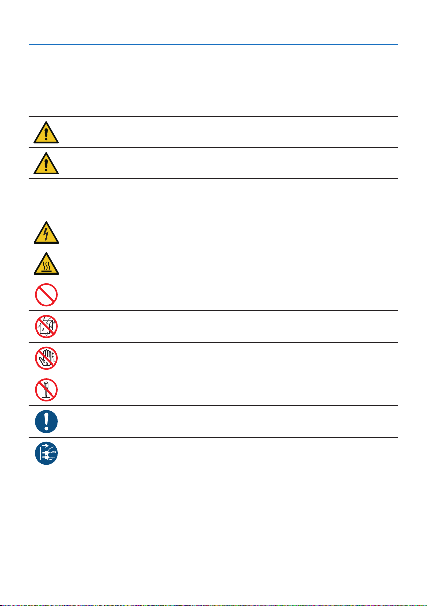
To ensure safe and proper use of the product, this manual uses a number of symbols to prevent
injury to you and others as well as damage to property.
The symbols and their meanings are described below. Be sure to understand them thoroughly
before reading this manual.
WARNING
CAUTION
Failing to heed this symbol and handling the product erroneously
could result in accidents leading to death or major injury.
Failing to heed this symbol and handling the product erroneously
could result in personal injury or damage to surrounding property.
Examples of symbols
This symbol indicates you should be careful of electric shocks.
This symbol indicates you should be careful of high temperatures.
This symbol indicates something that must be prohibited.
This symbol indicates something that must not be got wet.
This symbol indicates you should not touch with wet hands.
This symbol indicates something that must not be disassembled.
This symbol indicates things you must do.
This symbol indicates that the power cord should be unplugged from the power outlet.
vi
Page 8
Safety Cautions
Projected light
Projected light and the pictogram/label indicated on the cabinet
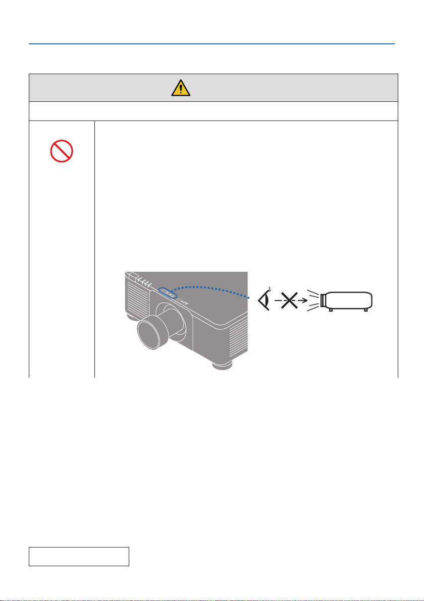
• Do not look into the projector’s lens.
Strong light that could damage your vision is projected when the projec-
PROHIBITED
• Do not look at the projected light using optical devices (magnifying glasses,
• Check that there is no one looking at the lens within the projection range
• Do not allow children to operate the projector alone. When a child is operating
• The below pictogram, that is indicated near the lens on the cabinet, describes
Important Information
WARNING
tor is operating. Laser energy exposure near aperture may cause burns. Be
especially careful when children are around.
reectors, etc.). Doing so could result in vision impairment.
before turning on the projector.
the projector an adult should always be present and watch the child carefully.
looking into the projector is prohibited.
Continue to next page
vii
Page 9
WARNING
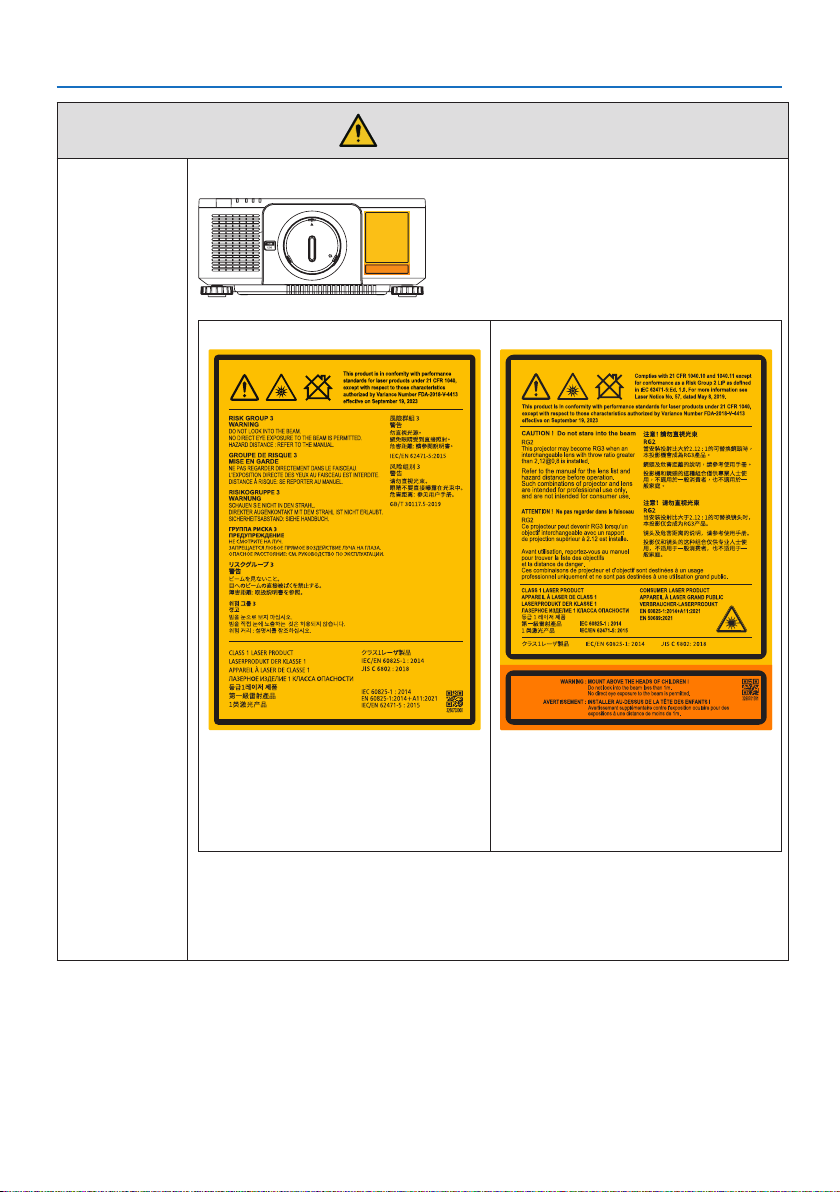
• The following labels are stuck on the projector.
X171Q-B/X171Q-W X141Q-B/X141Q-W
Important Information
This projector is classied as risk group 3
of IEC/EN 62471-5:2015.
• This product complies with EN 50689:2021
except using the lens of XP-62ZL.
• This projector is classied as either IEC/
EN 62471-5:2015 risk group 2 or risk
group 3 depending on the lens unit.
• When classied as risk group 3, this projector is intended for professional use
and must be installed by professional installer to ensure safety.
See page xix for risk groups.
• See page xvii for Laser Safety Caution.
viii
Page 10
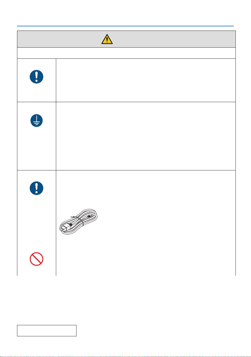
Power supply
REQUIRED
MUST BE
EARTHED
REQUIRED
Important Information
WARNING
Use a suitable voltage power supply.
• This projector is designed to be used with a 100–240 VAC, 50/60 Hz power
supply. Before using the projector, check that the power supply to which the
projector is to be connected meets these requirements.
• Use a power outlet as the projector’s power supply. Do not connect the
projector directly to electrical light wiring. Doing so is dangerous.
Connecting the power cord to earth
• This equipment is designed to be used in the condition of the power cord
connected to earth. If the power cord is not connected to the earth, it may
cause electric shock. Please make sure the power cord is connected to the
wall outlet directly and earthed properly.
Do not use a 2-pin plug converter adapter.
• Be sure to connect the projector and the computer (signal source) to the
same earth point. If the projector and the computer (signal source) will be
connected to dierent earth points, uctuations in the earth potential may
cause re or smoke.
Handling the power cord
• Please use the power cord supplied with this projector. If the supplied power
cord does not satisfy requirements of your country’s safety standard, and
voltage and current for your region, make sure to use the power cord that
conforms to and satises them.
• The power cord you use must be approved by and
comply with the safety standards of your country.
Please refer to the page 34 about the power cord
specication.
For selecting an appropriate power cord, please check
rated voltage for your region by yourself.
• The power cord included with this projector is exclusively for use with this
projector. For safety, do not use it with other devices.
PROHIBITED
Continue to next page
ix
Page 11

HAZARDOUS
VOLTAGE
DO NOT TOUCH
WITH WET
HANDS
Installation
PROHIBITED
DO NOT WET
UNPLUG THE
POWER CORD
Important Information
WARNING
• Handle the power cord with care. Damaging the cord could lead to re or
electric shock.
- Do not place heavy objects on the cord.
- Do not place the cord under the projector.
- Do not cover the cord with a rug, etc.
- Do not scratch or modify the cord.
- Do not bend, twist or pull the cord with excessive force.
- Do not apply heat to the cord.
Should the cord be damaged (exposed core wires, broken wires, etc.), ask
your dealer to replace it.
• Do not touch the power plug should you hear thunder. Doing so could result
in electric shock.
• Do not connect or disconnect the power cord with wet hands. Doing so could
result in electric shock.
Do not use in places such as those described below.
• Do not use in places such as those described below. Doing so could lead to
re or electric shock.
- Shaky tables, inclined surfaces or other unstable places.
- Poorly ventilated spaces.
- Near a radiator, other heat sources, or in direct sunshine.
- Continual vibration areas.
- Humid, dusty, steamy, or oily areas.
- An environment where there are corrosive gases (sulfur dioxide, hydrogen
sulde, nitrogen dioxide, chlorine, ammonia, ozone, etc.).
- Outdoors.
- High-temperature environment where humidity changes rapidly and
condensation is likely to occur.
• Do not use in places such as those described below where the projector could
get wet. Doing so could lead to re or electric shock.
- Do not use in the rain or snow, on a seashore or waterfront, etc.
- Do not use in a bathroom or shower room.
- Do not install under equipment that discharges water, such as air condition-
ers.
- Do not place vases or potted plants on the projector.
- Do not place cups, cosmetics or medicines on the projector.
Should water, etc. get inside the projector, rst turn o the projector’s power,
then unplug the power cord from the power outlet and contact your dealer.
x
Page 12
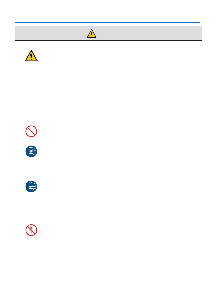
CAUTION
On use
PROHIBITED
UNPLUG THE
POWER CORD
Important Information
WARNING
Installing suspended from the ceiling
• Consult your dealer for installing the projector on the ceiling. Special skills
are required for ceiling installation.
DO NOT perform installation work by people other than installers. Doing so
may result in the projector falling and causing injury.
• We are not liable for any accident or/and damage resulting from improper
installation or handling, misuse, modication, or natural disasters.
• When installed suspended from the ceiling, etc. do not hang from the projector. The projector could drop and cause injury.
• When installing suspended from the ceiling, use a power outlet that is within
reach so the power cord can be easily plugged and unplugged.
Do not place objects inside the projector.
• Do not insert or drop metal or combustible objects or other foreign materials
into the projector from the vents. Doing so could lead to re or electric shock.
Be particularly careful if there are children in the home. Should a foreign object
get inside the projector, rst turn o the projector’s power, then unplug the
power cord from the power outlet and contact your dealer.
UNPLUG THE
POWER CORD
DO NOT
DISASSEMBLE
Unplug the power cord if the projector malfunctions.
• Should the projector emit smoke or strange odors or sounds, or if the projector has been dropped or the cabinet broken, turn o the projector’s power,
then unplug the power cord from the power outlet. Otherwise it may cause
not only re or electric shock but also serious damage to your eyesight or
burns. Contact your dealer for repairs.
Never try to repair the projector on your own. Doing so is dangerous.
Do not disassemble the projector.
• Do not remove or open the projector’s cabinet.
Also, do not modify the projector. There are high voltage areas in the projec-
tor. It may cause re, electric shock, or laser light leakage, resulting in serious
damage to your eyesight or burns.
Have qualied service personnel perform inspection, adjustments and repairs
of the interior.
xi
Page 13
PROHIBITED
CAUTION
FOR HIGH
TEMPERATURE
PROHIBITED
PROHIBITED
Important Information
WARNING
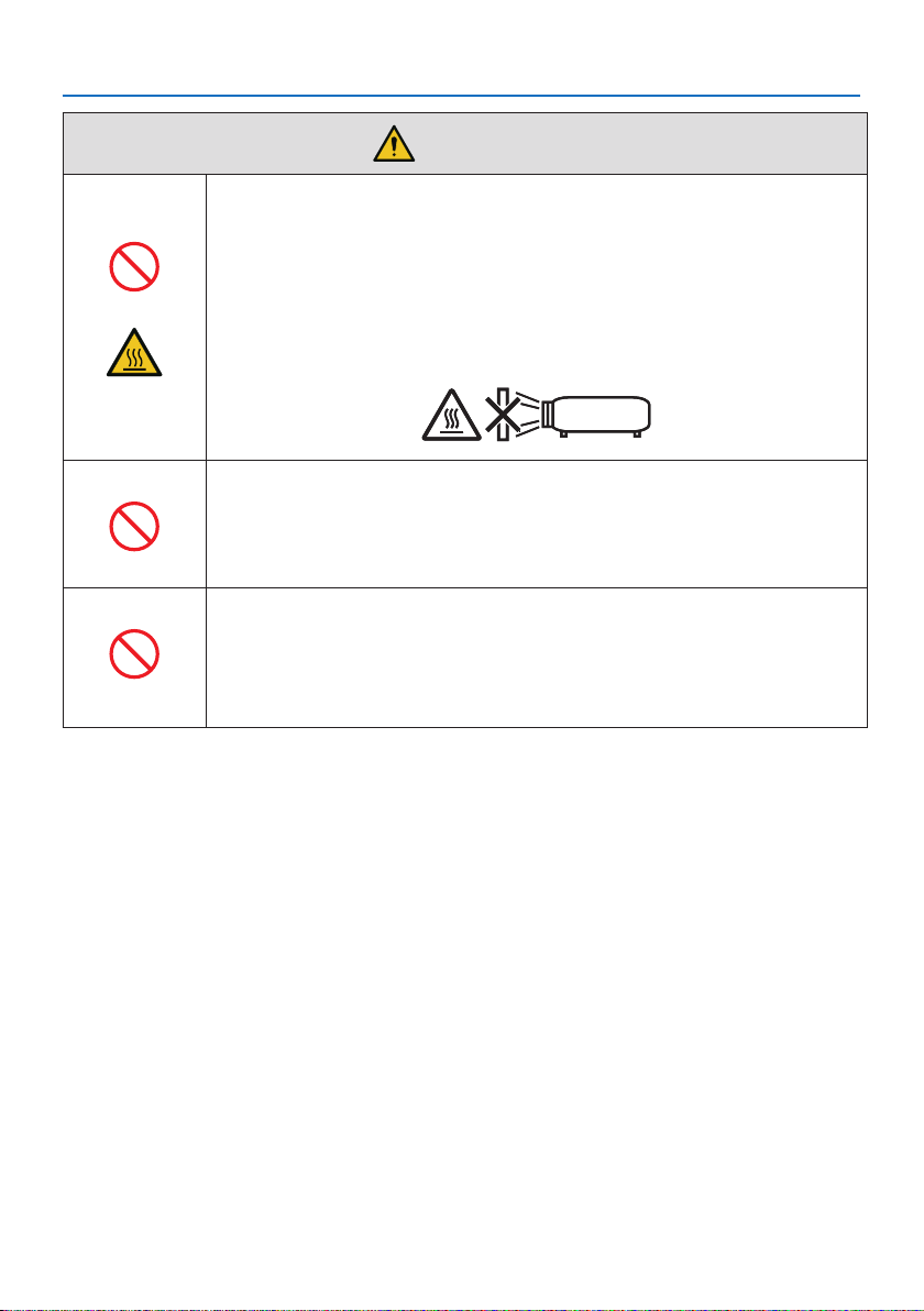
Do not place objects in front of the lens while the projector is
operating.
• Do not leave the lens cap on the lens while the projector is operating. The
lens cap could get hot and be warped.
• Do not place objects in front of the lens that obstruct the light while the
projector is operating. The object could get hot and be broken or catch re.
• The below pictogram indicated on the cabinet means the precaution for
avoiding to place objects in front of the projector lens.
When cleaning the projector
• Do not use ammable gas sprays to remove dust from the lens, cabinet, etc.
Doing so could lead to re.
Do not use in high security locations.
• Usage of the product must not be accompanied by fatal risks or dangers that,
could lead directly to death, personal injury, severe physical damage or other
loss, including nuclear reaction control in nuclear facility, medical life support
system, and missile launch control in a weapon system.
xii
Page 14
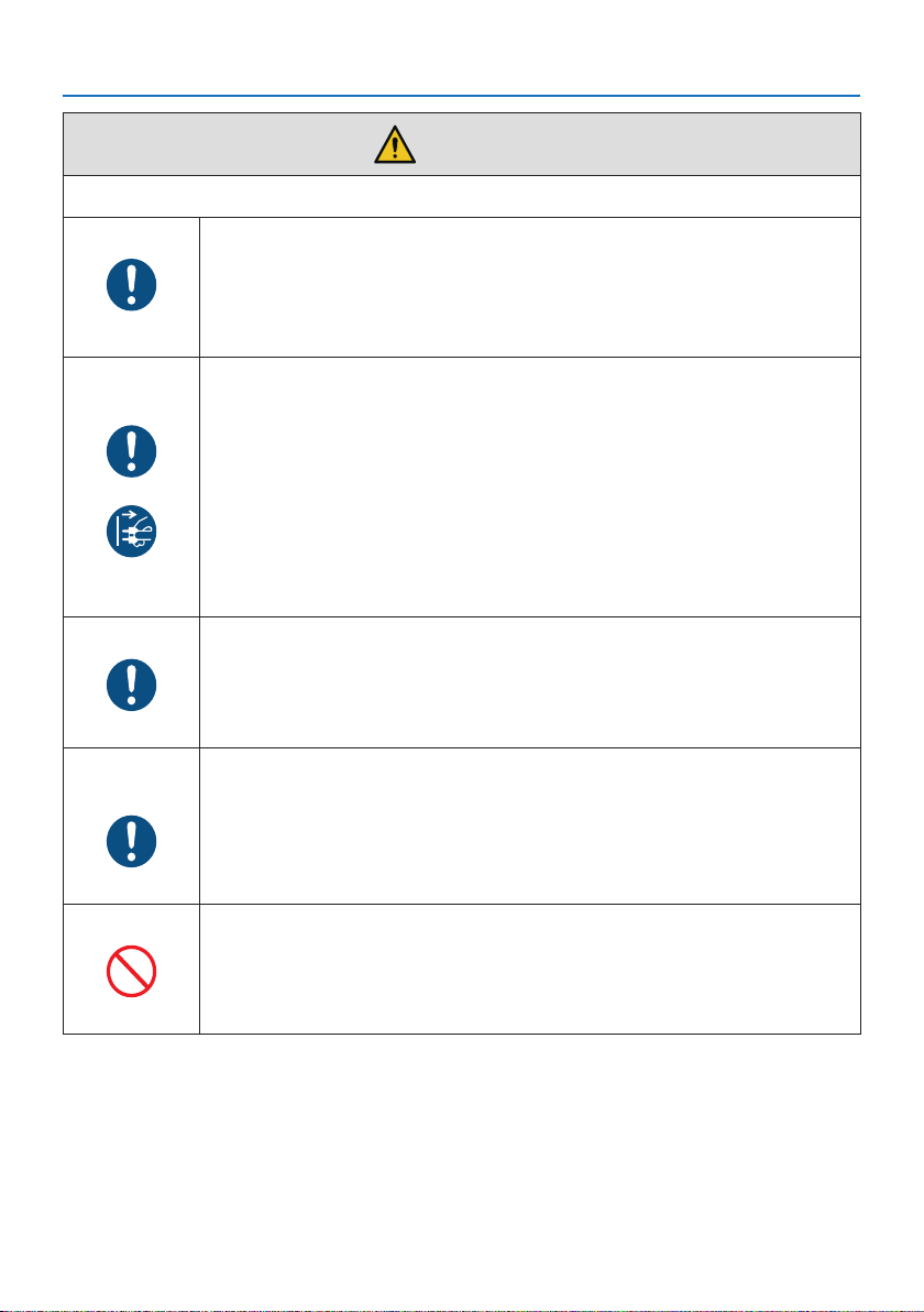
Power cord
REQUIRED
REQUIRED
UNPLUG THE
POWER CORD
Important Information
CAUTION
Handling the power cord
• The projector should be installed close to an easily accessible power outlet.
• When connecting the power cord to the projector’s AC IN terminal, make sure
the connector is fully and rmly inserted. Loose connection of the power cord
could lead to re or electric shock.
Handling the power cord by following below to avoid re or
electric shock
• When disconnecting the power cord, pull the power cord out by holding onto
its plug.
• Unplug the power cord from the power outlet before cleaning the product
or when not planning to use the product for an extended time.
• When the power cord or plug is heat or damaged, unplug the power cord
from the power outlet, and contact your dealer.
Periodically clean dust and other debris from the power plug
• Failure to do so could result in re or electric shock.
REQUIRED
REQUIRED
PROHIBITED
Disconnect power cords and other cables before moving the
projector
• Before moving the product, make sure the product power is o, then unplug
the power cord from the power outlet and check that all cables connecting
the product to other devices are disconnected.
Do not use the power cord with a power tap
• Adding an extension cord may lead to re as a result of overheating.
xiii
Page 15
Installation
REQUIRED
On use
PROHIBITED
REQUIRED
Important Information
CAUTION
Securing the lens unit with the fall prevention wire
• If the projector is going to be suspended from a ceiling or another high place,
secure the lens unit using the fall prevention wire (sold separately). If the lens
unit is not secured, it may fall down if it comes lose.
Do not use on networks subject to overvoltage.
• Connect the projector’s HDBaseT port and LAN port to a network for which
there is no risk of overvoltage being applied.
Overvoltage applied to the HDBaseT or LAN port could result in electric shock.
Lens shift, focus and zoom operations
• When shifting the lens or adjusting the focus or zoom, do so from either
behind or the side of the projector. If adjustments are performed from the
front, your eyes could be exposed to strong light and get injured.
• Keep your hands away from the lens area when performing the lens shift operation. If not, your ngers could get caught in the gap between the cabinet
and the lens.
xiv
Page 16
PROHIBITED
Important Information
CAUTION
Handling batteries
Incorrect usage of batteries can result in leaks or bursting.
• Use the specied batteries only.
• Insert batteries matching the (+) and (–) signs on each battery to the (+) and
(–) signs of the battery compartment.
• Do not mix battery brands.
• Do not combine new and old batteries. This can shorten battery life or cause
liquid leakage of batteries.
• Remove dead batteries immediately to prevent battery acid from leaking into
the battery compartment.
If leaked battery uid gets on your skin or clothing, rinse immediately and
thoroughly. If it gets into your eye, bathe your eye well rather than rubbing
and seek medical treatment immediately. Leaked battery uid that gets into
your eye or your clothing may cause a skin irritation or damage your eye.
• If you will not use the remote control for a long time, remove the batteries.
• Leaving a battery in an extremely high temperature surrounding environment, or a battery subject to extremely low air pressure, that can result in an
explosion or the leakage of ammable liquid or gas.
• Properly dispose of depleted batteries. Disposal of a battery into water, re,
or a hot oven, or mechanically crushing, cutting, or modifying a battery can
result in an explosion.
• Do not short-circuit the batteries.
• Do not charge the batteries. The batteries provided are not rechargeable.
• Contact your dealer or local authorities when disposing of batteries.
PROHIBITED
CAUTION
FOR HIGH
TEMPERATURE
About the vents
• Do not obstruct the projector’s vents. Also, do not place such soft objects as
paper or cloths underneath the projector. Doing so could lead to re.
Leave sucient space between the place where the projector is installed and
its surroundings. (→ page xxviii)
• Do not touch the exhaust vent area while projecting or immediately after
projecting images. The exhaust vent area may be hot at this time and touching it could cause burns.
xv
Page 17
PROHIBITED
REQUIRED
Important Information
CAUTION
Moving the projector
• After the lens unit removed, have at least two people hold the handles to
move the projector. Attempting to move the projector alone could result in
back pain or other injuries.
• When moving the projector, do not hold anywhere but the handles. Otherwise
the projector could fall and cause an injury.
• When carrying the projector with the lens unit removed, do not touch the
mounting area of the lens with your hands. Also, do not put your hand into
the recess of the connection terminal. The projector could be damaged or
fall down, resulting in injuries.
Attaching/detaching the lens
• Turn o the projector and disconnect the power cord before attaching or
detaching the lens unit. Failure to do so could result in visual impairment or
burns.
• Do not attach or detach the lens unit with the projector installed in a high
location.
The lens unit could fall and cause damage or injury.
Do not push or climb on the product. Do not grab or hang onto
the product. Do not rub or tap the product with hard objects.
• The product may fall, causing damage to the product or personal injury.
PROHIBITED
Avoid locations with extreme temperatures and humidity
• Failure to do so could lead to re or electric shock or damage to the projector.
The usage environment for this projector is as follows:
REQUIRED
- The operating temperature: 0°C to 45°C / 32°F to 113°F / humidity: 20 to
80% (without condensation)
- The storage temperature: -10°C to 60°C / 14°F to 140°F / humidity: 20 to
80% (without condensation)
Inspections and Cleaning
Inspecting the projector and cleaning the inside
• Consult with your dealer about once per year for cleaning of the inside of the
projector. Dust could accumulate inside of the projector if it is not cleaned
REQUIRED
for extended periods of time, leading to res or malfunction.
xvi
Page 18
Important Information
Laser Safety Caution
X171Q-B/X171Q-W
WARNING
CLASS 1 LASER PRODUCT [IEC 60825-1:2014]
• The laser module is equipped in this product. Use of controls or adjustments of procedures
other than those specied herein may result in hazardous radiation exposure.
Laser energy exposure near aperture may cause burns.
• This product is classied as Class 1 of IEC 60825-1:2014.
• For EU and UK, This product complies with EN 60825-1:2014+A11:2021.
• Obey the laws and regulations of your country in relation to the installation and management of
the device.
For USA
This product is in conformity with performance standards for laser products under 21 CFR 1040,
except with respect to those characteristics authorized by Variance Number FDA-2018-V-4413
eective on September 19, 2023.
X141Q-B/X141Q-W
WARNING
CLASS 1 LASER PRODUCT [IEC 60825-1:2014]
CLASS 1 CONSUMER LASER PRODUCT OF EN 60825-1:2014+A11:2021 (For EU and UK)
• The laser module is equipped in this product. Use of controls or adjustments of procedures
other than those specied herein may result in hazardous radiation exposure.
Laser energy exposure near aperture may cause burns.
• This product is classied as Class 1 of IEC 60825-1:2014.
• For EU and UK, This product complies with EN 60825-1:2014+A11:2021.
This product also complies with EN 50689:2021 except using the lens of XP-62ZL.
• Obey the laws and regulations of your country in relation to the installation and management of
the device.
For USA
Complies with 21 CFR 1040.10 and 1040.11 except for conformance as a Risk Group 2 LIP as
dened in IEC 62471-5:Ed. 1.0. For more information see Laser Notice No. 57, dated May 8, 2019.
However, when using the XP-62ZL lens, the following applies.
This product is in conformity with performance standards for laser products under 21 CFR 1040,
except with respect to those characteristics authorized by Variance Number FDA-2018-V-4413
eective on September 19, 2023.
xvii
Page 19

Important Information
WARNING (For USA)
• Do not allow to look into the projector beam at any distance from the projector. An adult
should supervise the children to prevent exposure risks.
• Check that there is no one looking at the lens, when using the remote control for starting the
projector.
• Do not look at the projected light using optical devices(binoculars, telescopes, magnifying
glasses, reectors, etc).
• [ WARNING: MOUNT ABOVE THE HEADS OF CHILDREN. ]
The use of a ceiling mount is recommended with this product to place it above the eyes of
children.
• Outline of laser emitted from the built-in light module:
- Wave length: 449 - 461 nm (blue), 635 - 651 nm (red)
- Maximum power: 456 W (blue), 72 W (red)
Light Module
• A light module containing multiple laser diodes is equipped in the product as the light source.
• These laser diodes are sealed in the light module. No maintenance or service is required for the
performance of the light module.
• End user is not allowed to replace the light module.
• Contact qualied distributor for light module replacement and further information.
xviii
Page 20
Important Information
Risk groups
X171Q-B/X171Q-W
This projector is classied as risk group 3 of IEC/EN 62471-5:2015.
X141Q-B/X141Q-W
This projector is classied as either IEC/EN 62471-5:2015 risk group 2 or risk group 3 depending
on the lens unit.
Risk group 2 (RG2)
WARNING
As with any bright light source, do not stare into the beam, RG2 IEC/EN 62471-5:2015.
Risk group 3 (RG3)
WARNING
RG3 PRODUCT OF IEC/EN 62471-5:2015
• When classied as RG3, this projector is for professional use and must be installed in location
where safety is assured. For this reason, be sure to consult your dealer as installation must be
performed by a professional installer. Never try to install the projector by yourself. This may
result in visual impairment etc.
• No direct exposure to the beam shall be permitted, RG3 IEC/EN 62471-5:2015.
• Do not look into the projector’s lens. Serious damage to your eyes could result.
• Operators shall control access to the beam within the hazard distance or install the product
at the height that will prevent exposures of spectators’ eyes within the hazard distance.
• When turning on the power, operate from the side or rear of the projector (outside the hazard
zone). Also, when turning on the power, make sure no one within the projection range is looking at the lens.
xix
Page 21
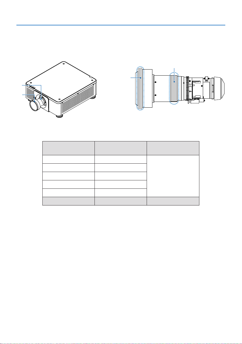
• Check before installing the projector (For X141Q-B/X141Q-W)
① Lens model name or throw ratio
The lens model name and throw ratio are listed in the image below.
b
a
b
a: Lens model name / b: Throw ratio
② Combining lens units and risk groups
Important Information
a
Lens model name Throw ratio
XP-57UL 0.31 - 0.33
XP-58ZL 0.55 - 0.75
XP-59ZL 0.74 - 1.08
XP-60ZL 1.05 - 1.41
XP-61ZL 1.40 - 2.11
XP-62ZL 2.10 - 4.00 RG3
X141Q-B
X141Q-W
RG2
xx
Page 22
Important Information
• Hazard zone
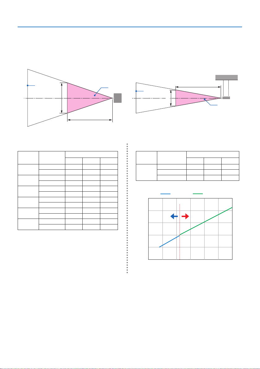
The below gure describes the radiation zone (hazard zone) of light emitted by the projector that
is classied as Risk Group 3 (RG3) of IEC/EN 62471-5:2015.
Overhead view Side view
a
H
HD
b
a
V
a: Screen / b: Hazard zone
X171Q-B/X171Q-W X141Q-B/X141Q-W
Lens
XP-57UL
XP-58ZL
XP-59ZL
XP-60ZL
XP-61ZL
XP-62ZL
Throw ratio
0.31 (Wide) 0.13 0.41 0.26
0.33 (Tele) 0.14 0.41 0.26
0.55 (Wide) 0.23 0.42 0.26
0.75 (Tele) 0.40 0.53 0.33
0.74 (Wide) 0.33 0.53 0.33
1.08 (Tele) 0.60 0.60 0.38
1.05 (Wide) 0.48 0.54 0.34
1.41 (Tele) 0.73 0.57 0.35
1.40 (Wide) 0.62 0.49 0.31
2.11 (Tele) 1.16 0.58 0.36
2.10 (Wide) 1.18 0.57 0.36
4.00 (Tele) 2.53 0.66 0.41
Hazard zone (m)
HD H V
Throw ratio
Lens
2.10 (Wide) - - -
XP-62ZL
2.12 (Middle) 1.00 0.49 0.31
4.00 (Tele) 2.11 0.56 0.35
2.5
2.0
XP-61ZLXP-62ZL
2.12
RG2
1.5
1.0
HD [m]
0.5
0.0
1.00 1.50 2.00 2.50 3.00 3.50 4.00
Throw ratio
HD
b
Hazard zone (m)
HD H V
RG3RG3RG3
Calculation of the throw ratio
Throw ratio = L: Throw distance (m) / W: Screen width (m)
For throw distances and screen widths, refer to “Lens types and throw distance” in the installation
manual.
xxi
Page 23
Important Information
• About the precautionary zone
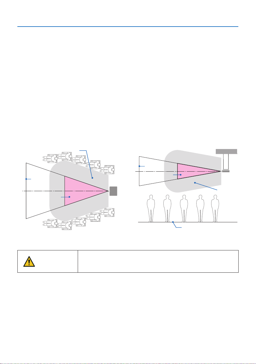
By providing a precautionary zone or physical barriers, it is possible to prevent human eyes from
entering the hazard zone.
When the manager of the projector (operator) cannot prevent spectators from entering the hazard
zone such as in public facilities, it is recommended to secure a space of 1 m or more from the hazard zone as “the precautionary zone” for the safety of the spectators. When installing the projector
overhead, it is recommended that the distance between the oor and the hazard zone be at least
3 m in the vertical direction.
In the United States, provide a horizontal distance of 2.5 meters from the hazard zone.
When install the projector overhead, provide a vertical distance of 3 meters from the oor to the
hazard zone.
• Installation example considering the precautionary zone (For lens units other
than XP-57UL)
① Floor or desktop installation example
c
a
b
a: Screen / b: Hazard zone / c: Precautionary zone / d: oor
If it is expected that spectators will intrude into the hazard zone when
CAUTION
installed on the ceiling, it is necessary to prevent spectators from
entering that area.
② Ceiling installation example
a
b
c
d
xxii
Page 24
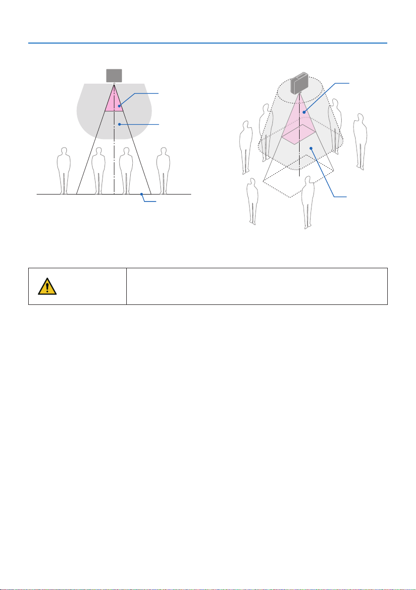
③ Example of downward projection installed on the ceiling
Important Information
b
b
c
d
d
a: Screen / b: Hazard zone / c: Precautionary zone / d: oor
If the precautionary zone between the oor and the hazard zone can-
CAUTION
* If using lens shift, please consider the shift of projected image according to the volume of lens shift. Instal-
lation example considering the precautionary zone
not be secured, it is necessary to prevent spectators from entering the
area around the screen as shown in the gure on the right.
c
xxiii
Page 25
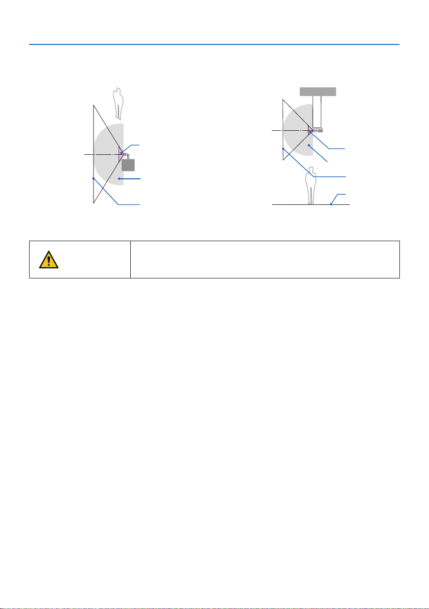
Important Information
• Installation example considering the precautionary zone (For XP-57UL)
① Floor or desktop installation example
b
c
a
a: Screen / b: Hazard zone / c: Precautionary zone / d: Floor
If the precautionary zone cannot be secured between the oor and
CAUTION
* The above gure is an example of a typical installation. It is also necessary to secure the precau-
tionary zone when installing the projector at an angle.
the hazard zone, spectators must be restricted from entering the space
between the projector and screen.
② Ceiling installation example
b
c
a
d
xxiv
Page 26

Important Information
CAUTION
Please follow all safety precautions.
Installing the projector
• When planning the layout of the projector, make sure to follow the safety measures listed in
the installation Manual.
• In order to avoid danger, either install the device within easy reach of a wall outlet or provide
a device like a breaker to disconnect power to the projector in emergency.
• Take safety measures to prevent human eyes from entering the hazard zone.
• Select an appropriate lens for the installation location and secure the safety zone set for each
lens.
Ensure that appropriate safety measures have been taken when operating the projector,
adjusting the light, etc.
• Check whether the appropriate safety zone for the installed lens has been adequately secured.
Periodically check the zone and maintain a record of verications.
The installer or dealer must instruct the manager (operator) of the projector of the following:
• Educate the manager of the projector (operator) about safety before operating the projector.
• Instruct the manager of the projector (operator) to perform inspections (Including safety
checks on light emitted by the projector) before powering the projector on.
• Instruct the manager of the projector (operator) to be able to control the projector whenever
the projector is powered on in case of an emergency.
• Instruct the manager of the projector (operator) to keep the installation Manual, user’s manual
and inspection records in an easy-to-reach place.
• Instruct them to determine whether the projector conforms to the standards of each country
and region.
xxv
Page 27

Important Information
Notes on installation and maintenance
Do not install or store in such places as those described below.
• Locations that amplify vibrations and impacts
If installed in places where the vibrations from power sources and the like are conveyed, or in
vehicles or on vessels, etc. the projector could be aected by vibrations or shocks that may damage internal parts and lead to malfunction.
• Close to high voltage power lines and power sources
It could disrupt the unit.
• Places where strong magnetic elds are generated
Doing so could lead to malfunction.
• Outdoors and places with humid or dust
Places exposed to oil smoke or steam
Places where corrosive gases are generated
Attached substances such as oil, chemicals and moisture may cause deformation or cracks of the
cabinet, corrosion of the metal parts, or malfunction.
To the dealer and the installer
When installing the projector, please see the Installation Manual provided on our website.
1. To prevent the projector from falling, install it on the ceiling in a way with sucient strength to
withstand the combined weight of the projector and the ceiling mount unit for an extended
period of time.
2. When installing the projector on the ceiling, be sure to do so correctly in accordance with the
installation Manual for the Ceiling Mount Unit. Be sure to use the xed metal ttings and to tighten
the screws securely.
3. To prevent the projector from falling, use fall prevention wires.
• Use commercially available metal ttings to join the robust part of a building or construction
and the security bar of the projector with the fall prevention wires.
• Use commercially available metal ttings and fall prevention wires that have sucient strength
to withstand the combined weight of the projector and the ceiling mount unit.
• Slightly slack o the fall prevention wires so as not to put a load on the projector.
• Refer to the “Part Names of the Projector” for the location of the security bar. (→ page 6)
Securing personal information
Personally identiable information, such as IP addresses, may be saved on the projector.
Before transferring or disposing of the projector, clear this data by performing [RESET] on the onscreen menu.
For items that cannot be reset, please clear them individually.
xxvi
Page 28

Important Information
Cautions for ensuring the projector’s performance
• If intense light like laser beams enters from the lens, it could lead to malfunction.
• Consult your dealer before using in places where much cigarette smoke or dust is present.
• When the projector is used at high altitudes (places where the atmospheric pressure is low), it
may be necessary to replace the optical parts sooner than usual.
• About moving the projector
- Detach the lens unit once, and be sure to attach the lens cap so as not to scratch the lens. Also,
attach a dust protective cap to the projector.
- Do not subject the projector to vibrations or strong shocks.
The projector could be damaged otherwise.
• Do not use the tilt feet for purposes other than adjusting the projector’s tilt.
Improper handling, such as carrying the projector by the tilt feet or using it leaned against a wall,
could lead to malfunction.
• Do not touch the surface of the projection lens with bare hands.
Fingerprints or dirt on the surface of the projection lens will be enlarged and projected on the
screen. Do not touch the surface of the projection lens.
• Do not unplug the power cord from the projector or the power outlet while projecting. Doing so
could cause deterioration of the projector’s AC IN terminal or power plug contact. To interrupt
the AC power supply while images are being projected, use a breaker, etc.
• About handling of the remote control
- The remote control will not work if the projector’s remote signal sensor or the remote control’s
signal transmitter is exposed to strong light or if there are obstacles between them that obstruct
the signals.
- Operate the remote control from within 7 meters from the projector, pointing it at the projec-
tor’s remote signal sensor.
- Do not drop the remote control or handle it improperly.
- Do not let water or other liquids get on the remote control. Should the remote control get wet,
wipe it o immediately.
- Avoid using in hot and humid places as far as possible.
• Take measures to prevent external light from shining on the screen.
Make sure only the light from the projector shines on the screen. The less external light on the
screen, the higher the contrast and the more beautiful the images.
• About screens
Images will not be clear if there is dirt, scratches, discoloration, etc. on your screen. Handle the
screen with care, protecting it from volatile substances, scratches and dirt.
• Concerning to all maintenance operations, refer to Installation Manual and follow all instructions
properly.
xxvii
Page 29
Important Information
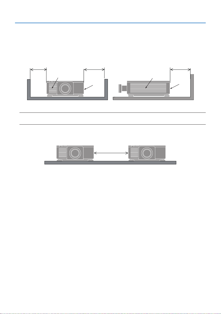
Clearance for Installing the Projector
• When installing the projector, keep sucient space around it, as described below. If not, the hot
exhaust emitted from the projector may be taken back in.
Also, make sure no wind from an air-conditioner hits the projector.
The projector’s heat control system may detect an abnormality (temperature error) and automati-
cally shut o the power.
dc
a
a
a
a: Intake vent / b: Exhaust vent / c: 30 cm/12" or greater / d: 50 cm/20" or greater
NOTE:
• In the above gure, it is assumed that there is sucient space above the projector.
• When using multiple projectors together for multi-screen projection, provide sucient space
around the projectors for air intake and exhaust. When the intake and exhaust vents are obstructed,
the temperature inside the projector will rise and this may result in a malfunction.
d
b
About Copyright of original projected pictures:
Please note that using this projector for the purpose of commercial gain or the attraction of public
attention in a venue such as a coee shop or hotel and employing compression or expansion of the
screen image with the following functions may raise concern about the infringement of copyrights
which are protected by copyright law.
[ASPECT RATIO], [KEYSTONE], Magnifying feature and other similar features.
REGISTER YOUR PROJECTOR! (for residents in the United States and Mexico)
Please take time to register your new projector. This will activate your limited parts and labor warranty and InstaCare service program.
Visit our website at https://www.sharpnecdisplays.us/product-registration and submit your com-
pleted form online.
Upon receipt, we will send a conrmation letter with all the details you will need to take advantage
of fast, reliable warranty and service programs from the industry leader, Sharp Imaging and Information Company of America.
xxviii
Page 30

Important Information
Trademarks
• ProAssist is trademark or registered trademark of Sharp NEC Display Solutions, Ltd. in Japan, in
the United State and other countries.
• The terms HDMI, HDMI High-Denition Multimedia Interface, HDMI Trade dress and the HDMI
Logos are trademarks or registered trademarks of HDMI Licensing Administrator, Inc.
• HDBaseT™ and the HDBaseT Alliance logo are trademarks of the HDBaseT Alliance.
• DisplayPort™ and the DisplayPort™ logo are trademarks owned by the Video Electronics Standards
Association (VESA®) in the United States and other countries.
• DLP® and the DLP logo are trademarks or registered trademarks of Texas Instruments in the United
States and other countries.
• Trademark PJLink is a trademark applied for trademark rights in Japan, the United States of America
and other countries and areas.
• Blu-ray is a trademark of Blu-ray Disc Association.
• Crestron™ and Crestron Connected ™ are trademarks or registered trademarks of Crestron Electronics, Inc. in the United States and other countries.
• Other product and company names mentioned in this user’s manual may be the trademarks or
registered trademarks of their respective holders.
xxix
Page 31

1. Check the product overview, supplied items and part names
1-1. Introduction to the Projector
This section introduces you to your new projector and describes the features and controls.
• Single-chip DLP projector with high resolution and high brightness
Realized to project the image in the resolution 3840 × 2400 pixels (4K), the aspect ratio in 16:10.
Model name Brightness
X171Q-B/X171Q-W 16500 lm (100 - 130 VAC: 14000 lm)
X141Q-B/X141Q-W 13500 lm
• A proprietary sealed structure that achieves highly dust-proof performance
Due to its excellent dust-proof performance, the projector is not equipped with a lter. Filter
replacement is therefore unnecessary.
• A long-life laser diode is equipped in the light module
The laser light source has a long service life, so replacement, adjustment, and other maintenance
should not be necessary for an extended period of time.
• Wide range of optional lenses selectable according to the place of installation
This projector supports 6 types of optional lenses, providing a selection of lenses adapted to a
variety of places of installation and projection methods.
Note that no lens is mounted upon shipment from the factory. Please purchase optional lenses
separately.
• 360 degree free projection
The projector is equipped with a “tilt-free” function for 360° projection vertically and a “roll-free”
function for 360° projection horizontally.
• Power lens control for quick and easy adjustment
By using buttons on the projector or the remote control, zoom, focus, and position (lens shift)
can be adjusted.
• A variety of input terminals such as HDMI, DisplayPort, HDBaseT, SDI, etc.
The projector is equipped with HDMI (1/2), DisplayPort (1/2), HDBaseT, SDI (IN/OUT) input
terminals.
The projector’s HDMI input terminals and DisplayPort input terminals support HDCP.
HDBaseT, promoted and advanced by the HDBaseT Alliance, is a consumer electronic (CE) and
commercial connectivity technology.
• Multi-screen projection using multiple projectors
You can line up multiple projectors to display a high resolution image in a larger screen.
Furthermore, the boundaries of the screens are smoothed using an edge blending function.
• Supports wired LAN
Equips the LAN and HDBaseT ports. Utilizing a wired LAN connected with these ports, it enables
to control the projector by a computer.
1
Page 32

1. Check the product overview, supplied items and part names
• Convenient utility software (User Supportware)
This projector supports our utility software.
NaViSet Administrator 2 helps you control the projector by a computer via wired LAN connec-
tion.
ProAssist is software allowing you for example to control the projector's lens from the computer
connected to the projector by a LAN cable. Some of the functions in ProAssist may not be compatible with the projector.
Please visit our website for downloading each software.
URL: https://www.sharp-nec-displays.com/dl/en/index.html
• Crestron Connected compatibility
The projector supports Crestron Connected, allowing multiple devices connected in the network
to be managed and controlled from a computer.
For details, refer to the Crestron Electronics, Inc. website.
https://www.crestron.com/
* The projector does not support XiO Cloud.
2
Page 33
1. Check the product overview, supplied items and part names
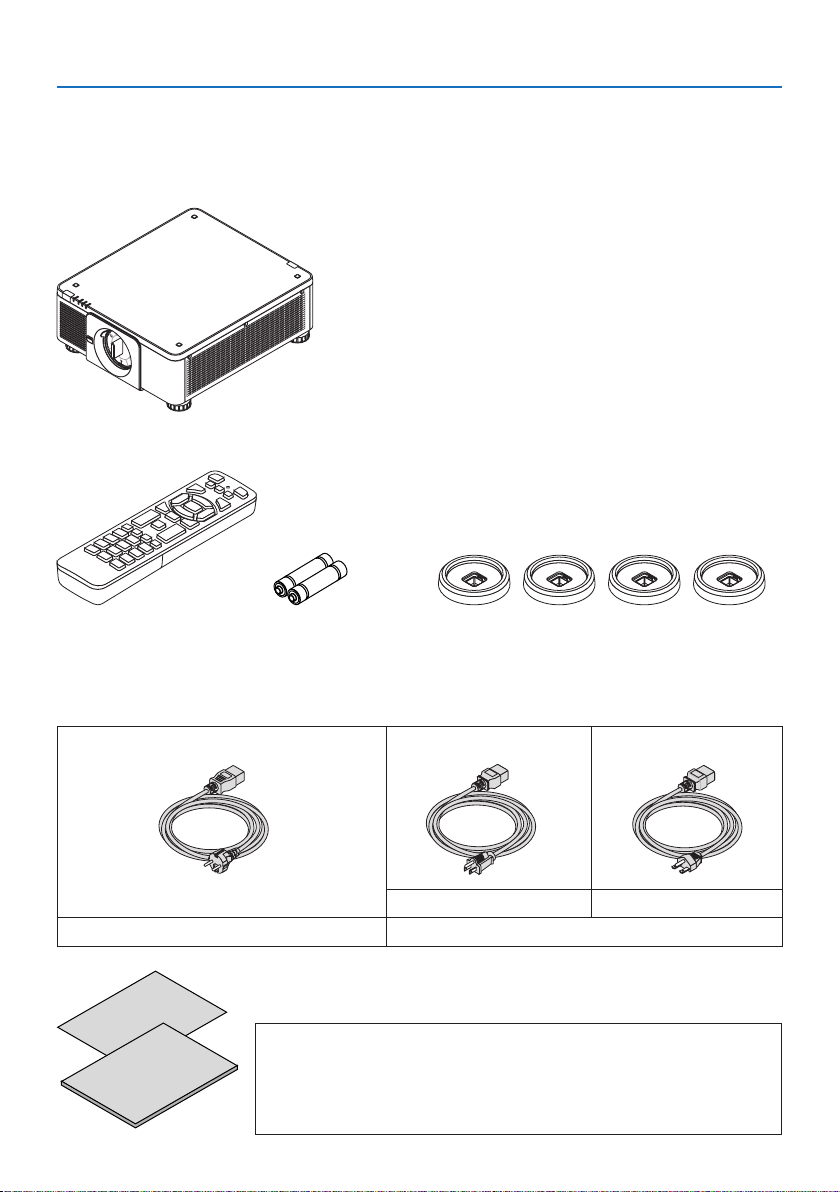
1-2. What’s in the Box?
Make sure your box contains everything listed. If any pieces are missing, contact your dealer.
Please save the original box and packing materials if you ever need to ship your projector.
Projector
Dust cap for lens
* The projector is shipped without a lens.
Remote control AAA alkaline batter-
ies (x2)
[X171Q-B/X171Q-W] Power cord (× 3)
[X141Q-B/X141Q-W] Power cord (× 2)
For Europe/Asia/South America For North America
• Important Infomation
• Quick Setup Guide
For USA only
Limited warranty
For customers in Europe
You will nd our current valid Guarantee Policy on our website:
https://www.sharpnecdisplays.eu
4 Stacking holders
(for AC 120 V) (for AC 200 V)
3
[X171Q-B/X171Q-W only]
Page 34
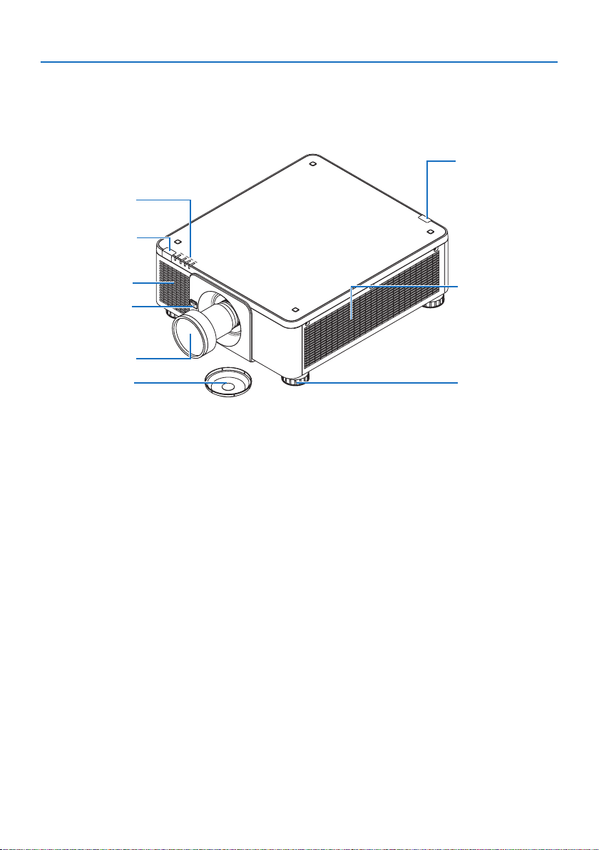
1. Check the product overview, supplied items and part names
1-3. Part Names of the Projector
Front
The lens is sold separately. The description below is for when the XP-61ZL lens is mounted.
4
3
4
2
7
5
6
1. Adjustable Tilt Foot
Rotate the tilt foot to adjust the left/right
orientation.
2. Intake vent
Takes in outside air to cool the unit.
3. Indicator Section
The indicator light turns on or blinks to
relay the status of the projector (Power ON/
Standby/etc.)
4. Remote Sensor
This part receives signals from the remote
control. There are two locations on the front
and back of the projector.
2
1
5. Lens
Images are projected from here. (Lens unit
sold separately.)
6. Lens Cap
(The optional lens is shipped with the lens
cap.)
7. Lens Release (LENS) Button
This is used to remove the lens unit.
4
Page 35
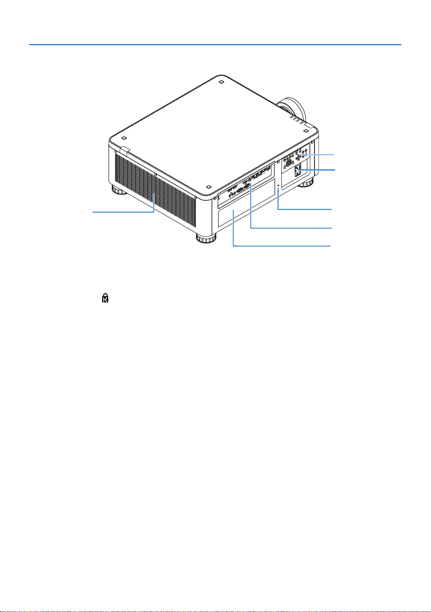
Rear
1. Check the product overview, supplied items and part names
3
5
1
1. Exhaust vent
Heated air is exhausted from here.
2. Security Slot ( )*
This is used when attaching an anti-theft
cable.
3. Controls
The projector's power can be turned ON/
OFF, and the signal for the projected image
can be switched here.
4. Terminals
Connect the cables for the various video
signals.
5. AC IN Terminal
Connect the supplied power cord's three-
pin plug here, and plug the other end into
an active wall outlet.
6. Label
2
4
6
* Security and theft protection lock compatible with Kensington security cables/equipment. For products,
visit Kensington’s website.
5
Page 36
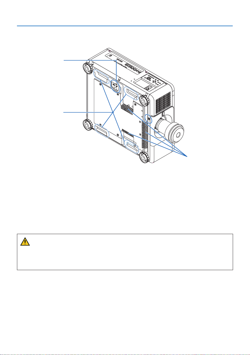
Bottom
1. Check the product overview, supplied items and part names
1
2
3
1. Security Bar
Attach an anti-theft device. The security bar
accepts security wires or chains up to 0.18
inch/4.6 mm in diameter.
2. Handle (located on 4 positions)
For transportation.
3. Intake vent
Takes in outside air to cool the unit.
CAUTION:
For moving the projector, make sure you have at least two people. At the same time, do not grip
and hold the projector other than by these handles. Attempting to move the projector alone
could result in back pain or other injuries.
6
Page 37
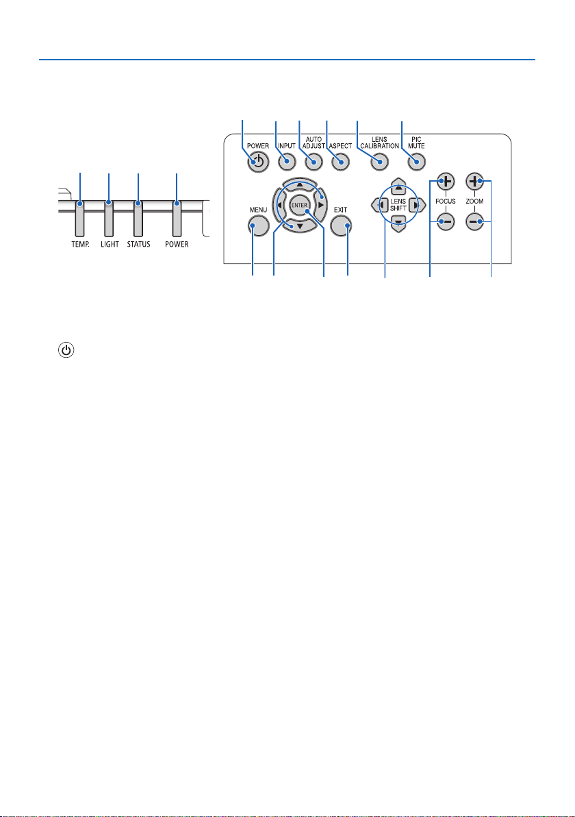
Controls/Indicators
1. Check the product overview, supplied items and part names
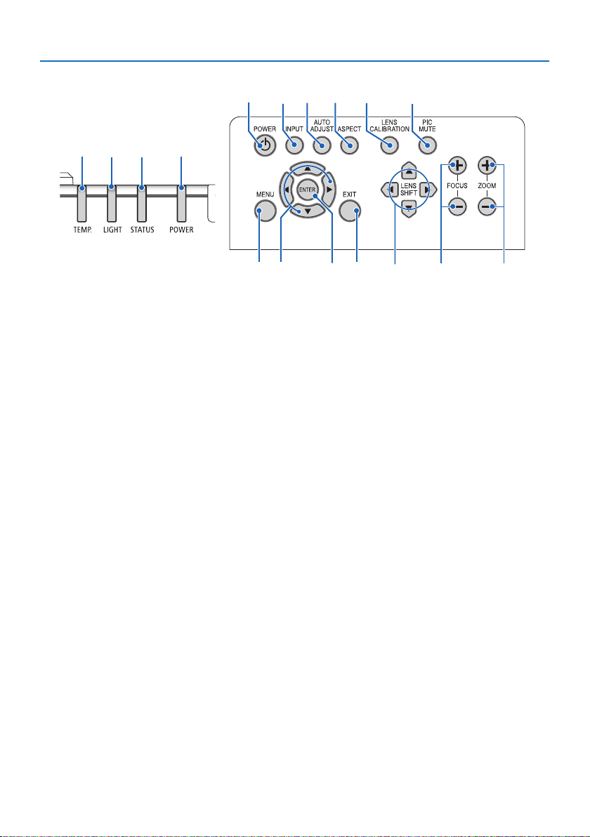
1
5
4
2
3
11
1. (POWER) Button
Switches between projector’s power on and
standby.
When turning off the power (standby),
pressing the button once will bring up a
confirmation message on the screen, so
press the button one more time.
2. POWER Indicator
Indicates the projector’s power state. The
indicator lights up in green when the power
is on. Depending on the state of power, it
will light up or blink in either red or orange
when power is o. Refer to the “Indicator
Message” section for details.
(→ page 36)
3. STATUS Indicator
This lights up or blinks when an operation
button is pressed while the unit is in key
lock mode, while the lens is calibrating, etc.
Refer to the “Indicator Message” section for
details.
(→ page 36)
4. LIGHT Indicator
Indicates the state of the light source.
6 7 8
9
10
14 15 16 1712 13
5. TEMP. Indicator
Indicates high temperatures around the
projector.
6. INPUT Button
Selects the input signal. Pressing it quickly
will display the input selection screen.
Pressing it for one second or longer will
begin a series of automatic checks in the
order of HDMI1 → HDMI2 → DisplayPort1
→ DisplayPort2 → HDBaseT → SDI, and if
an input signal is detected then that signal
will be projected.
7. AUTO ADJUST Button
Automatically adjusts the projected image
to the optimal condition.
8. ASPECT Button
This switches the aspect ratio each time it
is pressed.
9. LENS CALIBRATION Button
The lens unit and lens shift adjustment
range are calibrated and the lens is shifted
back to the home position.
7
Page 38
1. Check the product overview, supplied items and part names
1
5
4
2
3
11
10. PIC MUTE Button
Turns o the image for a short period of
time. Press the button again to unmute.
11. MENU Button
Displays the on-screen menu for various
settings and adjustments.
12. ▲▼◀▶ Buttons
• When the on-screen menu is displayed,
use the ▼▲◀▶ buttons to select the item
that you wish to set or adjust.
• Changes the pattern when the test pattern is displayed.
13. ENTER Button
Moves to the next menu when the on-
screen menu is displayed. Confirms the
item when the confirmation message is
displayed.
6 7 8
9
10
14 15 16 1712 13
14. EXIT Button
Close the menu when the on-screen menu
is displayed.
Cancels the operation when the conrma-
tion message is displayed.
15. SHIFT Button
Adjust the position of the projected image.
16. FOCUS Button
Adjust the focus of the projected image.
17. ZOOM Button
Adjust the size of the projected image.
8
Page 39
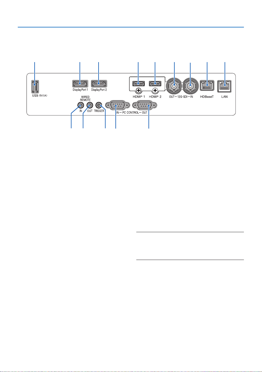
Terminal Panel Features
1. Check the product overview, supplied items and part names
9
10 13
1. HDMI 1 Terminal (Type A)
Connects to the output terminals of a com-
puter, blu-ray player, etc.
2. HDMI 2 Terminal (Type A)
Connects to the output terminals of a com-
puter, blu-ray player, etc.
3. SDI IN Terminal (BNC)
Connects to the SDI output terminal on the
video device.
4. SDI OUT Terminal (BNC)
Outputs the video signal input to the SDI IN
terminal.
5. HDBaseT Port (RJ-45)
Connects to a commercially available
HDBaseT compatible transmission devices.
6. LAN Port (RJ-45)
Connects the unit to a wired LAN.
7. DisplayPort 1 Terminal
Connects to the DisplayPort output terminal
on a computer, etc.
847
11 12
21
63 5
14
8. DisplayPort 2 Terminal
Connects to the DisplayPort output terminal
on a computer, etc.
9. USB Port (Type A)
Supplies a 5.0V/2.0A power source when the
projector’s power is turned on.
10. WIRED REMOTE IN Terminal (Stereo
Mini)
Use this terminal for wired remote control
of the projector.
NOTE:
• When a remote control cable is connected to the REMOTE
terminal, infrared remote control operations cannot be
performed.
9
Page 40
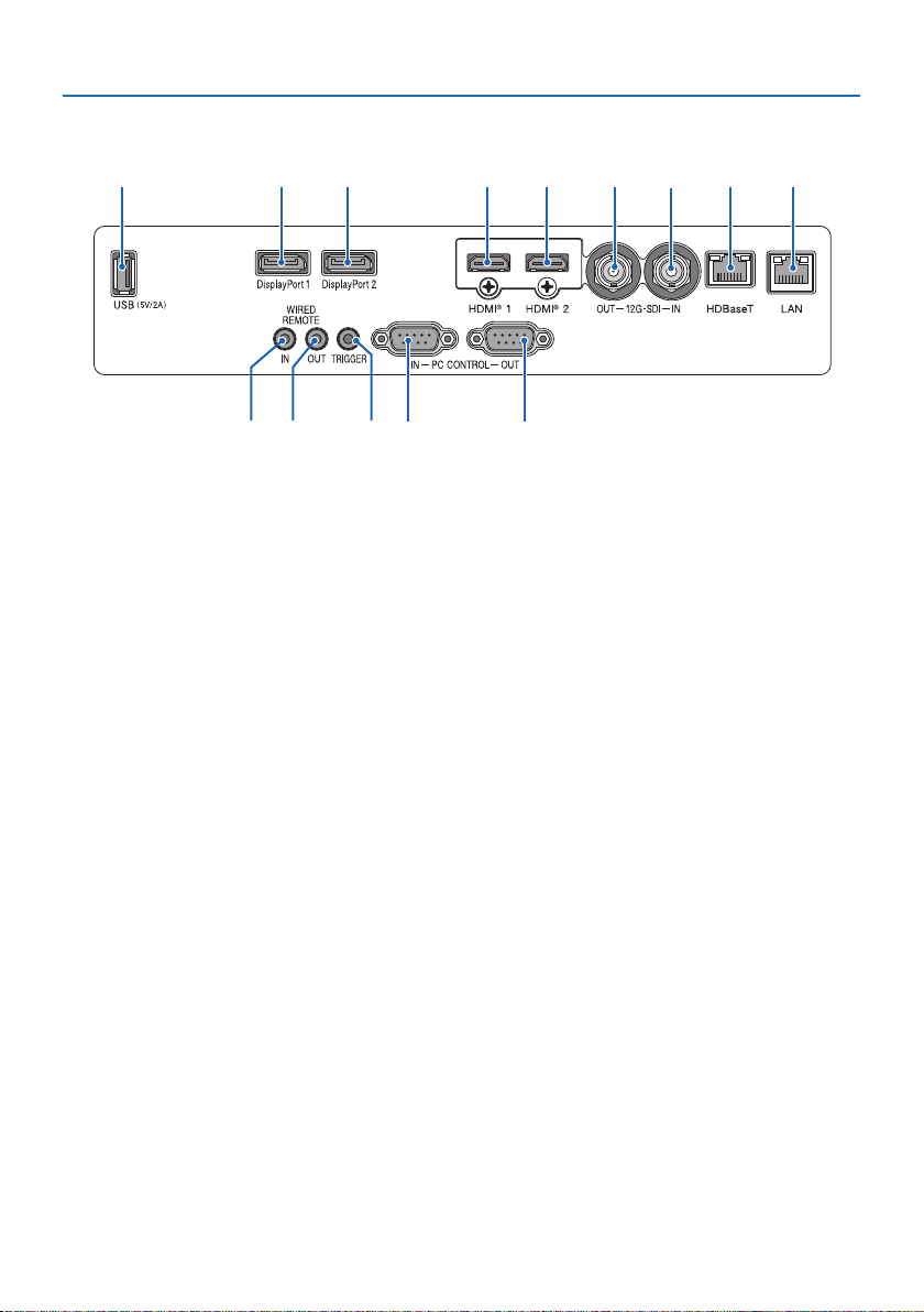
1. Check the product overview, supplied items and part names
9
10 13
11. WIRED REMOTE OUT Terminal
Outputs the video signal input to the WIRED
REMOTE IN terminal.
12. TRIGGER Terminal
When the projector’s power is turned on,
outputs a control voltage for the screen.
Connect a screen controller or other device
to control such things as the screen height
when the projector’s power is turned on and
o.
13. PC CONTROL IN Port (D-Sub 9 Pin)
Use this port to connect a PC or control
system. This enables you to control the projector using serial communication protocol.
14. PC CONTROL OUT Port (D-Sub 9 Pin)
Outputs the control signal input to the PC
CONTROL IN port.
847
11 12
14
21
63 5
10
Page 41
1. Check the product overview, supplied items and part names
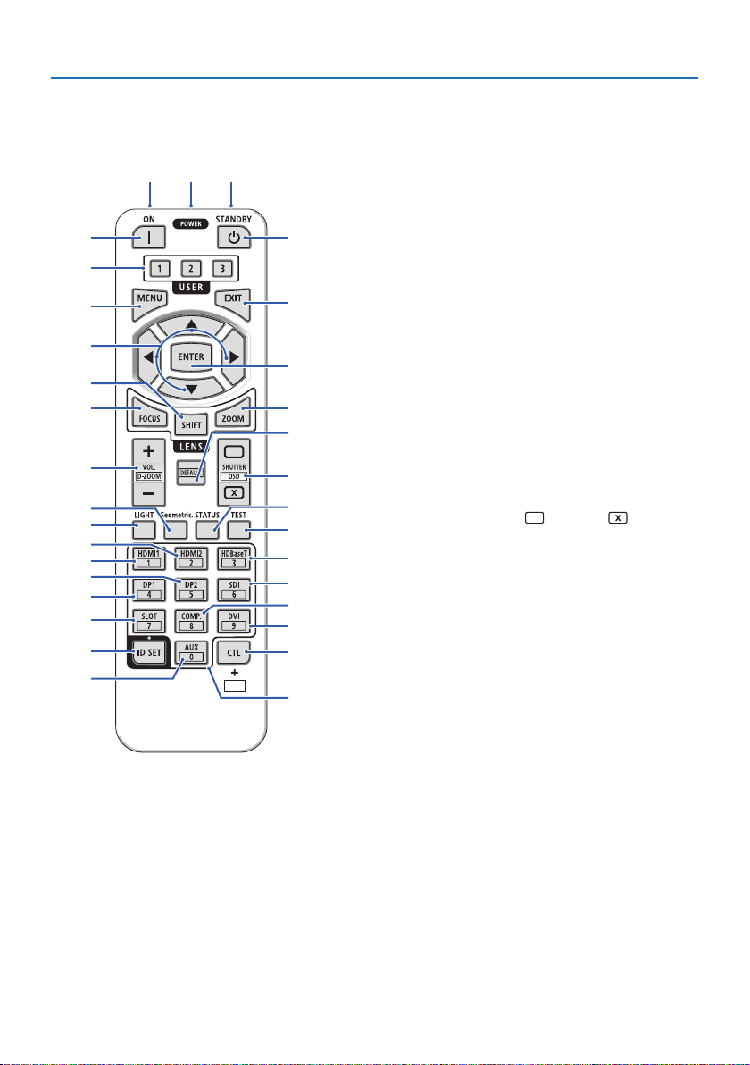
1-4. Part Names of the Remote Control
11
10
13
17
16
21
20
24
23
26
30
29
112
3
5
6
8
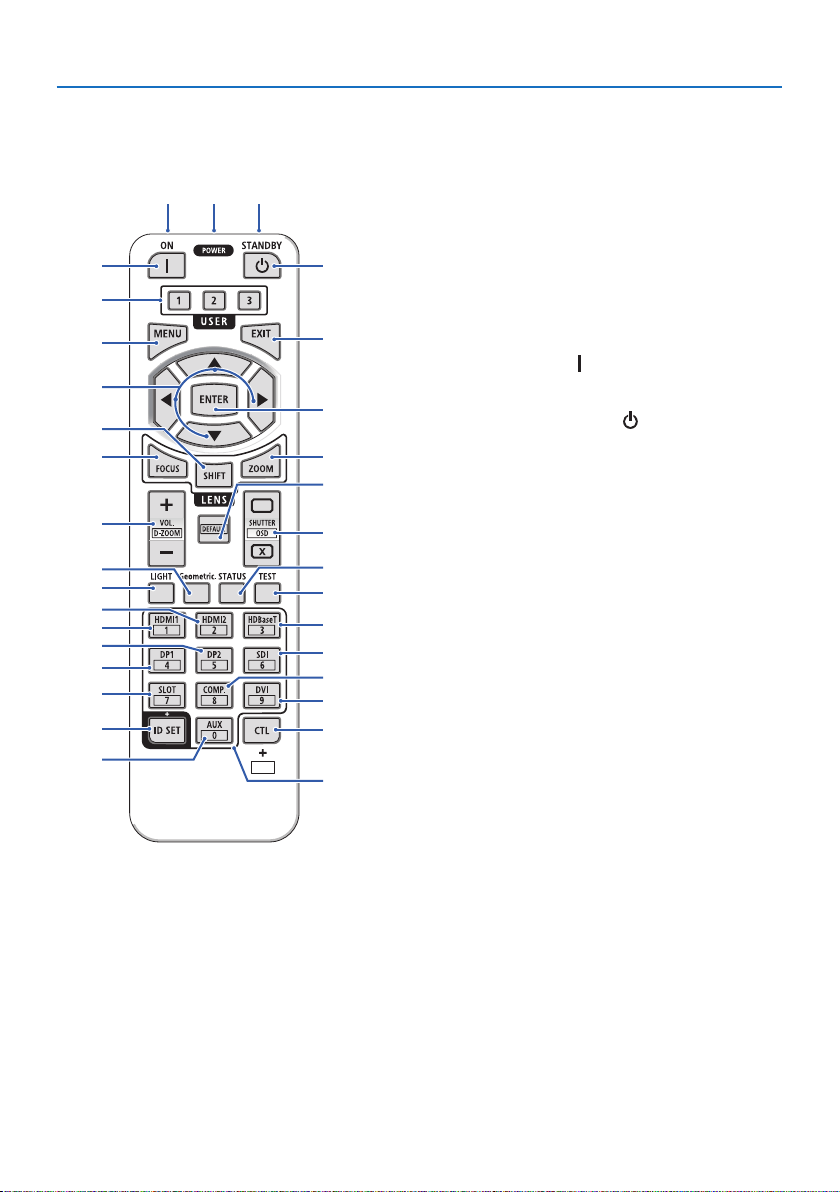
1. Infrared Transmitter
Remote control signals are sent via infrared signal.
Point the remote control at the remote control
4
7
9
12
14
15
18
19
22
25
27
28
32
31
receiver on the projector.
2. Remote Jack
Connect a commercially available remote cable
here for wired operation.
3. POWER ON Button ( )
Turns power ON when in standby mode.
4. POWER STANDBY Button ( )
Pressing the button once will display the shutdown
conrmation message. Press the POWER STANDBY
(or ENTER) button once more to power down the
projector.
5. USER 1/2/3 Button
USER1: Automatically adjusts the projected im-
age to the optimal condition.
USER2/ 3: (Not available on this series of projectors.)
6. MENU Button
Displays the on-screen menu for various settings
and adjustments.
7. EXIT Button
Closes the menu when the on-screen menu is
displayed. Cancels the operation when the conrmation message is displayed.
8. ▲▼◀▶ Button
• When the on-screen menu is displayed, use the
▼▲◀▶ buttons to select the item that you wish
to set or adjust.
• Changes the pattern when the test pattern is
displayed.
9. ENTER Button
Moves to the next menu when the on-screen menu
is displayed. Conrms the item when the conrmation message is displayed.
11
Page 42
1. Check the product overview, supplied items and part names
11
10
13
17
16
21
20
24
23
26
30
29
112
3
5
6
8
10. FOCUS Button
Opens the focus adjustment screen. Adjust the
focus (of the lens) with the ◀ / ▶ buttons.
11. SHIFT Button
4
The lens shift adjustment screen will be displayed.
Use the ▼▲◀▶ buttons to adjust the lens position.
12. ZOOM Button
7
Opens the zoom adjustment screen. Adjust zoom
with the ▼▲ buttons.
9
13. VOL./D-ZOOM (+)(−) Button
Simultaneously pressing the CTL button will ex-
12
14
15
18
19
22
25
27
28
32
31
pand or shrink the image (return to the original
state).
14. DEFAULT Button
(Not available on this series of projectors.)
15. SHUTTER/OSD OPEN ( )/CLOSE ( ) Button
Press the CLOSE button to turn o the light source
and temporarily stop projection. Press the OPEN
button to resume. Simultaneously press the CTL
and CLOSE buttons to close the on-screen display
(On-Screen Mute). Simultaneously press the CTL
and OPEN buttons to go back.
16. LIGHT Button
This switches [REF. LIGHT MODE] each time it is
pressed.
17. Geometric. Button
Displays [DISPLAY] from the on-screen menu.
18. STATUS Button
Displays [INFO.] from the on-screen menu.
19. TEST Button
Projects a test pattern.
20. HDMI1 Button
Selects the HDMI1 input.
21. HDMI2 Button
Selects the HDMI2 input.
12
Page 43
1. Check the product overview, supplied items and part names
11
10
13
17
16
21
20
24
23
26
30
29
112
3
5
6
8
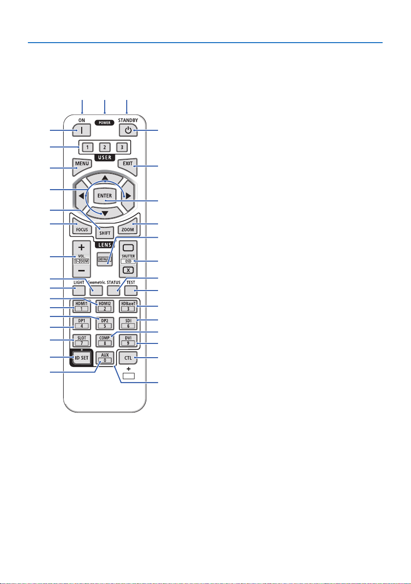
22. HDBaseT Button
Selects the HDBaseT input.
23. DP1 Button
Selects the DisplayPort1 input.
4
24. DP2 Button
Selects the DisplayPort2 input.
7
25. SDI Button
Selects the SDI input.
26. SLOT Button
9
(Not available on this series of projectors.)
12
27. COMP. Button
14
(Not available on this series of projectors.)
28. DVI Button
15
(Not available on this series of projectors.)
18
29. AUX Button
19
(Not available on this series of projectors. For future
22
25
27
28
32
31
expansion)
30. ID SET Button
Used to set the control ID when performing indi-
vidual operations on multiple projectors using the
remote control.
31. Numeric Keypad Button
Used to input the control ID when performing indi-
vidual operations on multiple projectors using the
remote control (set the control ID). Pressing the 0
button while holding down the ID SET button will
remove any control ID settings.
32. CTL Button
This is a multipurpose button for combined use
with other buttons.
13
Page 44
1. Check the product overview, supplied items and part names
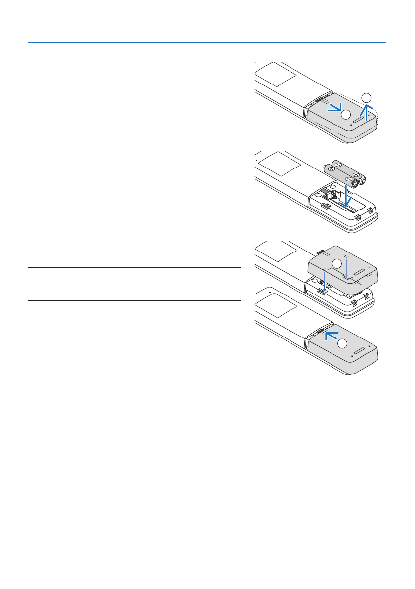
Battery Installation
1. Press the catch and remove the battery cover.
2. Install AAA alkaline batteries. Ensure that you have
the batteries’ polarity (+/−) aligned correctly.
3. Slip the cover back over the batteries until it snaps
into place.
NOTE:
• When replacing the batteries, purchase 2 of the same type of AAA alkaline
batteries.
2
1
1
2
Remote Control Precautions
• Handle the remote control carefully.
• If the remote control gets wet, wipe it dry immediately.
• Avoid excessive heat and humidity.
• Do not short, heat, or take apart batteries.
• Do not throw batteries into re.
• If you will not be using the remote control for a long time, remove the batteries.
• Ensure that you have the batteries’ polarity (+/−) aligned correctly.
• Do not use new and old batteries together, or use dierent types of batteries together.
• Dispose of used batteries according to your local regulations.
• Please note that if multiple projectors are installed nearby, other projectors may unintentionally
light up when you turn on the power using the remote control.
14
Page 45
1. Check the product overview, supplied items and part names
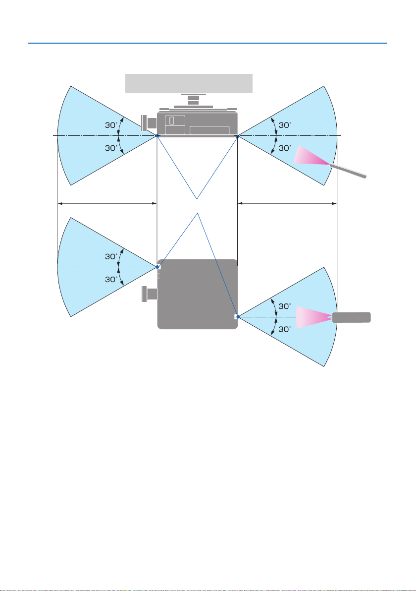
Operating Range for Wireless Remote Control
c
aa
b
c
a: 7 m/276" / b: Remote sensor on projector cabinet / c: Remote control
• The projector will not respond if there are objects between the remote control and the sensor,
or if strong light falls on the sensor. Weak batteries will also prevent the remote control from
properly operating the projector.
15
Page 46
1. Check the product overview, supplied items and part names
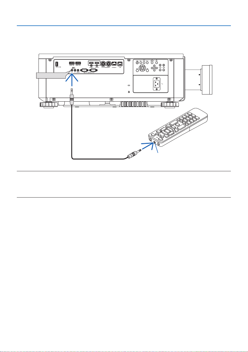
Using the Remote Control in Wired Operation
Connect one end of the remote cable to the REMOTE terminal and the other end to the remote
jack on the remote control.
REMOTE IN
a
a: Remote jack
NOTE:
• When a remote cable is inserted into the REMOTE terminal, the remote control does not work for infrared wireless communication.
• Power will not be supplied to the remote control by the projector via the REMOTE jack. Battery is needed when the remote control
is used in wired operation.
16
Page 47

2. Projecting an Image (Basic Operation)
This section describes how to turn on the projector and to project a picture onto the screen.
2-1. Flow of Projecting an Image
Step 1
• Connecting your computer / Connecting the power cord (→ page 18)
Step 2
• Turning on the projector (→ page 20)
Step 3
• Selecting a source (→ page 23)
Step 4
• Adjusting the picture size and position (→ page 24)
Step 5
• Making a presentation
Step 6
• Turning o the projector (→ page 31)
Step 7
• After use (→ page 32)
17
Page 48

2. Projecting an Image (Basic Operation)
2-2. Connecting Your Computer/Connecting the Power Cord
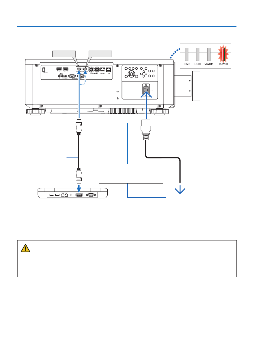
1. Connect your computer to the projector.
This section will show you a basic connection to a computer.
Connect a commercially available HDMI cable between the computer's HDMI output connector
and the projector's HDMI 1 IN or HDMI 2 IN connector.
2. Connect the supplied power cord to the projector.
First connect the supplied power cord’s three-pin plug to the AC IN terminal of the projector,
and then connect another plug of the supplied power cord directly in the wall outlet. Do not
use any plug converter.
CAUTION:
• This equipment is designed to be used in the condition of the power cord connected to
earth. If the power cord is not connected to the earth, it may cause electric shock. Please
make sure the power cord is connected to the wall outlet directly and earthed properly.
Do not use a 2-core plug converter adapter.
• Be sure to connect the projector and the computer (signal source) to the same earth point.
If the projector and the computer (signal source) will be connected to dierent earth
points, uctuations in the earth potential may cause re or smoke.
• To prevent the power cord from coming loose, make sure that all the prongs of the power
cord plug are fully inserted into the AC IN terminal of the projector. A loose contact of the
power cord may cause a re or electric shock.
Upon connecting the power cable, the POWER indicator of the projector will light.
18
Page 49
2. Projecting an Image (Basic Operation)
HDMI 1
HDMI 2
b
Make sure that the prongs are
fully inserted into both the AC
IN and the wall outlet.
a: Power cord (supplied) / b: HDMI cable (not supplied)
a
To wall outlet
• Use a Premium High Speed HDMI Cable.
CAUTION:
Parts of the projector may become temporarily heated if the projector is turned o with the
POWER button or if the AC power supply is disconnected during normal projector operation.
Use caution when picking up the projector.
19
Page 50
2. Projecting an Image (Basic Operation)
2-3. Turning on the Projector
WARNING
The projector produces a strong light. When turning on the power, operate from the side or rear
of the projector (outside the hazard zone). Also, when turning on the power, make sure no one
within the projection range is looking at the lens.
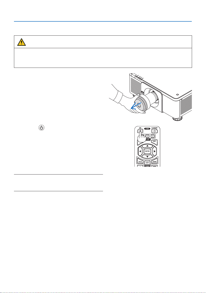
1. Remove the lens cap.
2. Press the (POWER) button on the projector cabinet or the POWER ON button on the
remote control.
The POWER indicator lit in red will start to
blink in green. After that, the image will be
projected onto the screen.
After you turn on your projector, ensure that
the computer or video source is turned on.
NOTE:
• A blue screen (blue background) is displayed when no signal is
being input (by factory default menu settings).
20
Page 51

Performing Lens Calibration
After installation or replacement of the lens, be
sure to perform [LENS CALIBRATION] by pressing
the LENS CALIBRATION button on the projector
cabinet. Perform [LENS CALIBRATION] also when
trouble is found on the lens shift motion. Calibration corrects the adjustable lens shift range. Also,
perform [LENS CALIBRATION] when an error occurs
in the lens shift operation.
2. Projecting an Image (Basic Operation)
21
Page 52
2. Projecting an Image (Basic Operation)
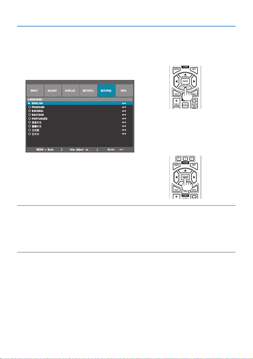
Note on Startup screen (Menu Language Select screen)
When you rst turn on the projector, you will get the Startup menu. This menu gives you the opportunity to select one of the 9 menu languages.
To select a menu language, follow these steps:
1. Use the ▲ or ▼ button to select one of the 9
languages from the menu.
2. Press the ENTER button to execute the selection.
After this has been done, you can proceed to the
menu operation.
If you want, you can select the menu language
later.
NOTE:
• Keep the lens cap o the lens while the projector’s power is on.
If the lens cap is on, it could be warped due to high temperature.
• While the POWER indicator is blinking green in short cycles, the power cannot be turned o by using the power button.
• If the projector is kept in sleep mode or other similar state, the temperature of the internal components could rise even when the
projector is being used within its normal operating temperate. If the power is turned on in that state, the cooling fan will turn on
and the image will be projected after a short while.
22
Page 53
2. Projecting an Image (Basic Operation)
2-4. Selecting a Source
Selecting the computer or video source
NOTE:
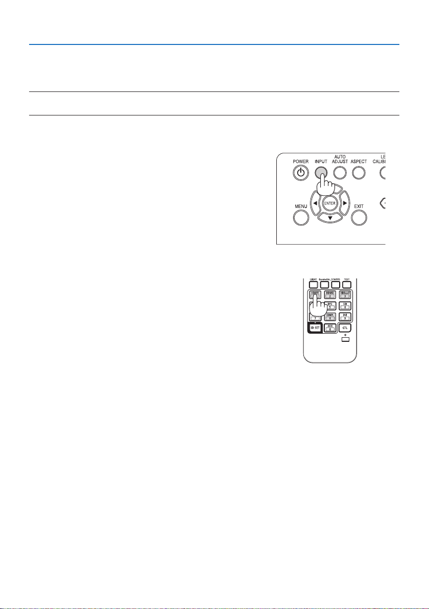
• Turn on the computer or video source equipment connected to the projector.
Using the buttons on the projector cabinet
Pressing the INPUT button will switch to the next input source.
HDMI1 → HDMI2 → DisplayPort1 → DisplayPort2 → HDBaseT
→ SDI → HDMI1 → …
Using the Remote Control
Press the HDMI1 or HDMI2 button.
23
Page 54
2. Projecting an Image (Basic Operation)
2-5. Adjusting the Picture Size and Position
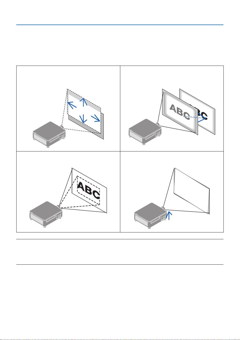
Use the lens shift, the adjustable tilt foot, the zoom and the focus to adjust the picture size and
position.
Repeat these adjustments until you obtain the optimal projection conditions.
In this chapter drawings and cables are omitted for clarity.
Adjusting the projected image’s vertical and
horizontal position
“Lens shift” (→ page 25)
Finely adjusting the size of an image
“Zoom” (→ page 29)
Adjusting the focus
“Focus” (→ page 27)
Adjusting the projected image’s inclination
“Tilt foot” (→ page 30)
NOTE:
• The SHIFT, FOCUS and ZOOM buttons on the remote control will not function while the test pattern is being projected. When
using the remote control, adjust the setting by pressing the MENU button to open the on-screen menu and then selecting
[DISPLAY]→[LENS]→[LENS CONTROL].
24
Page 55
2. Projecting an Image (Basic Operation)
X
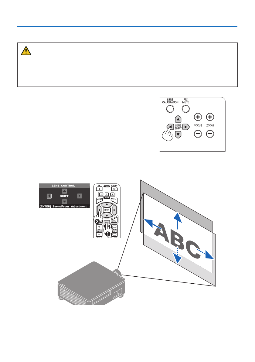
Adjusting the vertical position of a projected image (Lens shift)
CAUTION
• Perform the adjustment from behind or from the side of the projector. If adjustments are
performed from the front, your eyes could be exposed to strong light and get injured.
• Keep hands away from the lens mounting portion while performing a lens shift. Failure to do
so could result in ngers being pinched by the moving lens.
Using the buttons on the projector cabinet
1. Press the LENS SHIFT▼▲◀▶buttons to move the
projected image.
Using the Remote Control
1. Press the SHIFT button.
The [LENS CONTROL (SHIFT)] screen will be displayed.
2. Press the ▼▲◀▶ buttons to move the projected image.
X
25
Page 56
2. Projecting an Image (Basic Operation)
To set back the lens to the home position
Press the LENS CALIBRATION button. The lens mounted on the projector goes back to the home
position. (roughly to the center position)
NOTE:
• If the lens is shifted to the maximum in the diagonal direction, the screen peripheral area will be dark or shaded.
TIP:
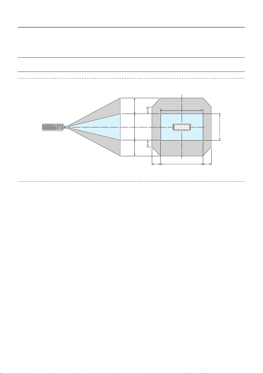
• The gure below shows the lens shift adjustment range (projection method: Desktop/Front) of the XP-61ZL lens unit.
60 %V
100 %V
60 %V
25 %V
25 %V
20 %H 20 %H
H
V
100 %H
Description of symbols: V indicates vertical (height of the projected image), H indicates horizontal (width of the projected image).
26
Page 57
2. Projecting an Image (Basic Operation)
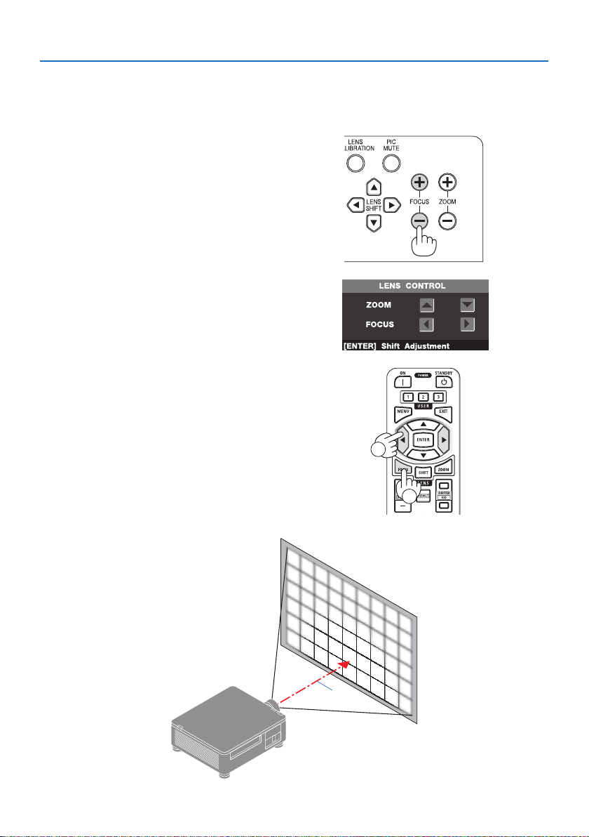
FOCUS
① Adjust the focus around the optical axis (Powered focus)
Using the buttons on the projector
cabinet
1. Press the FOCUS (+) or (–) button to align
focus around the optical axis.
* The picture shows and example when
the lens shift is moved upward. Adjust
the lens until the bottom edge of the
projection screen is in focus.
Using the Remote Control
1. Press the FOCUS or ZOOM button.
The [LENS CONTROL (ZOOM/FOCUS)] screen
will be displayed on.
2. Press either ◀ or ▶ button to align focus
around the optical axis.
2
a: Optical axis
27
1
X
a
Page 58
2. Projecting an Image (Basic Operation)
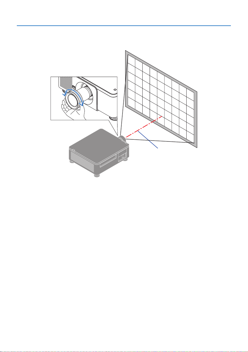
② Adjust the focus of screen peripheral area (Manual focus)
Turn the peripheral focus ring clockwise or counterclockwise.
a
③ Repeat steps ① and ② until the entire projection screen is in focus.
28
Page 59
Zoom
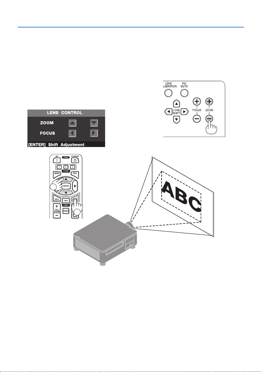
Using the buttons on the projector cabinet
1. Press the ZOOM (+) or (-) button to adjust zoom.
Using the Remote Control
1. Press the ZOOM or FOCUS button.
The [LENS CONTROL (ZOOM/FOCUS)] screen will
be displayed on.
2. Press ▲▼ button to adjust zoom.
2
2. Projecting an Image (Basic Operation)
1
X
29
Page 60
Adjusting the Tilt Foot
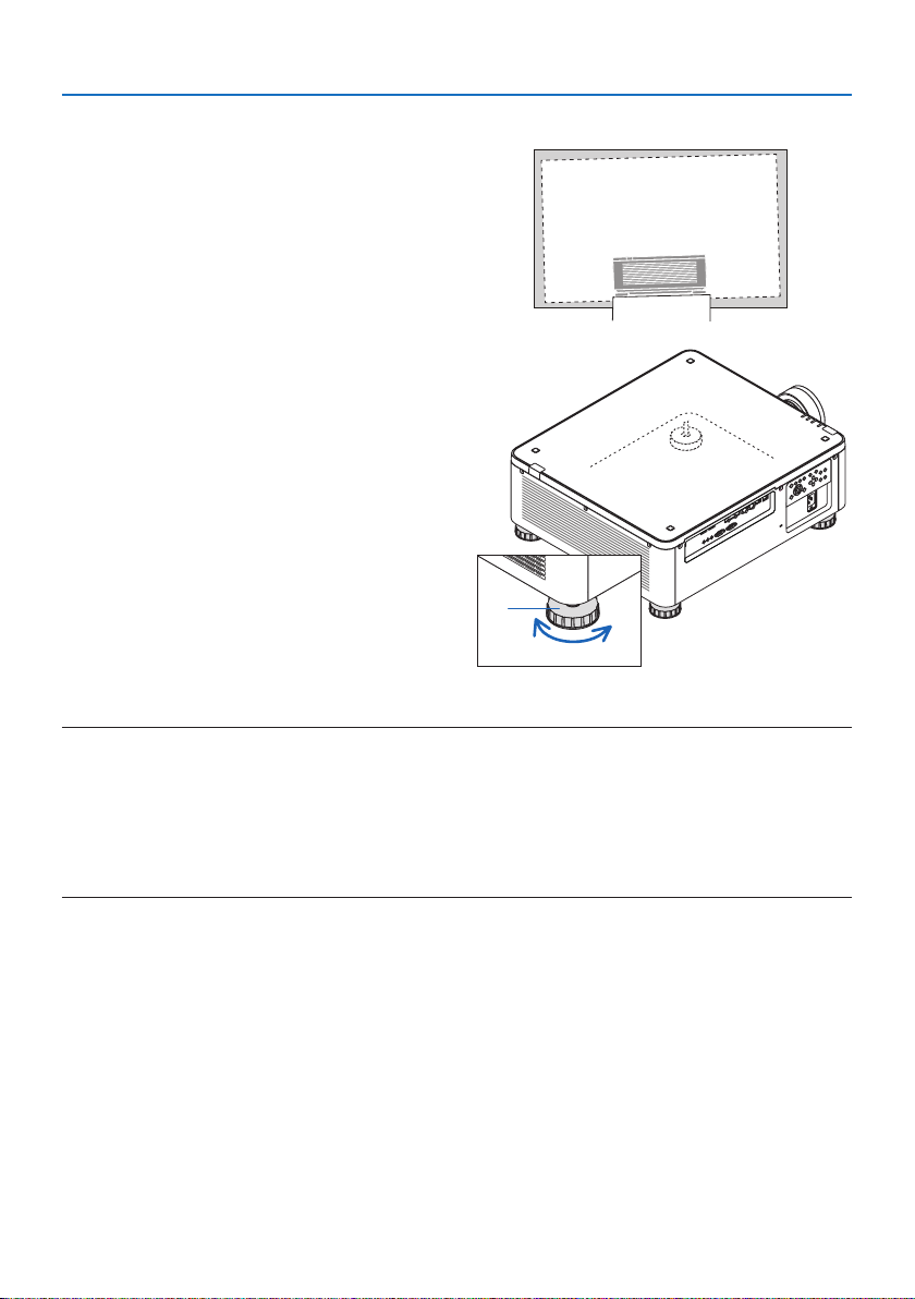
1. The position to project image may be adjusted by the tilt foot positioned at four
corners of the cabinet bottom.
The tilt foot height can be adjusted by its turn.
"To adjust the height of the projected image"
The height of the projected image is adjusted
by turning either front or rear tilt foot.
"If the projected image is tilted"
If the projected image is tilted, turn either left
or right tilt foot to adjust the image so that it
is level.
• The tilt foot can be lengthened by a maxi-
mum of 10 mm.
• The tilt foot can be used to tilt the projector
by a maximum of 1°.
2. Projecting an Image (Basic Operation)
a
bc
a: Tilt foot / b: Up / c: Down
NOTE:
• Do not lengthen the tilt foot any more than 10 mm/0.4". Doing so will make the projector unstable.
• Pay attention to lengthen or shorten two tilt foot at front at the same time. Same for the rear foot, otherwise, the weight of the
projector is loaded on one side and it may cause of damage to it.
• Do not use the tilt foot for any purpose other than adjusting inclination of the projector installation angle.
Handling the tilt foot improperly, such as carrying the projector by grasping the tilt foot or hooking it onto a wall using the tilt
foot, could damage the projector.
30
Page 61
2. Projecting an Image (Basic Operation)
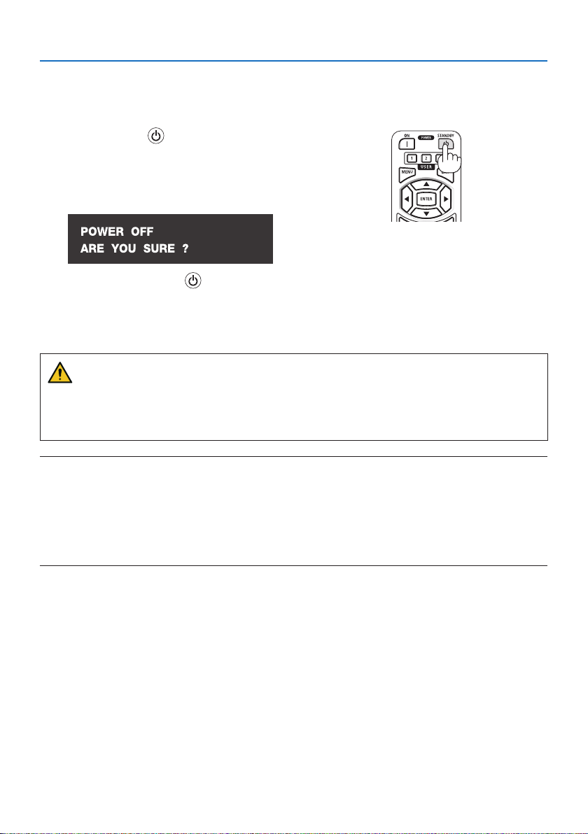
2-6. Turning off the Projector
To turn o the projector:
1. First, press the (POWER) button on the
projector cabinet or the STANDBY button on
the remote control.
The [POWER OFF / ARE YOU SURE ?] message
will appear.
2. Secondly, press the (POWER) or the
STANDBY button again.
The light source will be turned o and the power
supply will be cut.
CAUTION
• Parts of the projector may become temporarily heated if the projector is turned o with the
POWER button or if the AC power supply is disconnected during normal projector operation.
Use caution when picking up the projector.
NOTE:
• While the POWER indicator is blinking green in short cycles, the power cannot be turned o.
• Do not unplug the power cord from the projector or from the power outlet while an image is being projected. Doing so could
deteriorate the projector’s AC IN terminal or the power plug’s contact. To turn o the AC power while an image is being projected,
use the breaker, etc.
• Do not disconnect the AC power supply to the projector within 10 seconds of making adjustment or setting changes and closing
the menu. Doing so can cause loss of adjustments and settings.
31
Page 62

2. Projecting an Image (Basic Operation)
2-7. After Use
1. Unplug the power cord.
2. Disconnect any other cables.
3. Mount the lens cap on the lens.
4. Before moving the projector, screw in the tilt foot if they have been lengthened.
32
Page 63
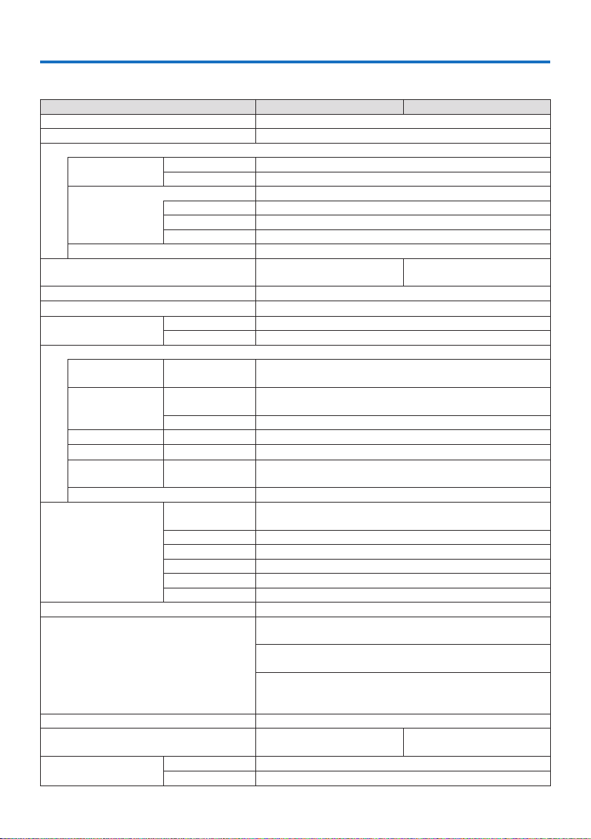
3. Appendix
3-1. Specifications
Model name X171Q-B/X171Q-W X141Q-B/X141Q-W
Method Single DLP® chip
Resolution 9,216,000 pixcels (3840 dots × 2400 lines)
Specications of main parts
DMD panel Size 0.8" (aspect ratio: 16:10)
Projection lenses Refer to the specications of option lens (→ 35 page)
Light source Laser diode with Phosphor
Light output
(*2) (*3)
Screen size (throw distance) 50" - 600" (Throw distance depends on the lens)
Color reproducibility 10-bit color processing (approx. 1.07 billion colors)
Scanning frequency Horizontal 15 kHz, 24 to 153 kHz
Input/output connectors
HDMI 1/2 Video input Type A × 2
HDBaseT Video input RJ-45 x1,
SDI IN
SDI OUT
DisplayPort 1/2
USB USB type A × 1, 5.0 V/2.0 A power supply
Control Terminals LAN RJ-45 × 1, 10BASE-T/100BASE-TX,
Built-in Speaker Not applicable
Usage environment
(*5)
Power supply 100-240 VAC, 50/60 Hz
Power consumption 1080 W (100-130VAC)
Power consumption
(Standby state)
Pixels
(*1)
2,304,000 (1920 dots × 1200 lines)
Zoom Motorized
Focus Motorized
Lens shifting Motorized
16500 lm
13500 lm
(100 - 130 VAC: 14000 lm)
Vertical 24, 25, 30, 48 Hz, 50 to 85 Hz, 100, 120 Hz
Deep Color, LipSync, HDCP
Deep Color, LipSync, HDCP
(*4)
, 4K
(*4)
, 4K
Control 100BASE-TX, PJLink class1
Video input BNC x1 12G
Video output
Video input DisplayPort × 2
BNC x1 12G
Deep Color, LipSync, HDCP
(*4)
, 4K
PJLink class1
PC CONTROL IN D-Sub 9-pin × 1
PC CONTROL OUT D-Sub 9-pin × 1
WIRED REMOTE IN Stereo mini jack × 1
WIRED REMOTE OUT
Stereo mini jack × 1
TRIGGER Stereo mini jack × 1
Operating temperature: 32 to 113°F (0 to 45°C)
Operating humidity: 20 to 80% (with no condensation)
Storage temperature: 14 to 140°F (−10 to 60°C)
Storage humidity: 20 to 80% (with no condensation)
Operating altitude: 0 to 3000 m/10000 feet
(1499 - 3000 m / 5000 - 10000 feet : Set [FAN MODE] to
[HIGH])
1290 W (200-240VAC)
1080 W (100-240 VAC)
Network enabled 2.0 W (100-240 VAC)
Network disabled 0.5 W (100-240 VAC)
33
Page 64

3. Appendix
Model name X171Q-B/X171Q-W X141Q-B/X141Q-W
Rated input current 12.0 A (100-130VAC) –
6.0 A (200-240VAC)
Power cord speci�cation 15 A or higher
External dimensions 19.7" (width) × 8.3" (height) × 22.7" (depth)/
500 mm (width) × 211 mm (height) × 577 mm (depth)
(not including protruding parts)
19.7" (width) × 8.5" (height) × 23.0" (depth)/
500 mm (width) × 216 mm (height) × 583 mm (depth)
(including protruding parts)
Weight 65.5 lbs/29.7kg
(not including lens)
*1 Eective pixels are more than 99.99%.
*2 This is the brightness when lens unit XP-61ZL (sold separately) is attached and [REF. LIGHT MODE] is set to
[NORMAL], [REF. LIGHT ADJUST] is set to [100] (100 - 130 VAC: [85]), and [PRESET] is set to [STANDARD]. Using
[REF. LIGHT ADJUST] will reduce brightness. If any other mode is selected as the [PRESET] mode, the light
output value may drop slightly.
*3 Compliance with ISO21118-2020
*4 If you are unable to view material via the HDMI input, this does not necessarily mean the projector is not
functioning properly. With the implementation of HDCP, there may be cases in which certain content is
protected with HDCP and might not be displayed due to the decision/intention of the HDCP community
(Digital Content Protection, LLC).
Video: HDR, Deep Color, 8/10/12-bit, Lip Sync.
HDMI: Supports HDCP 2.2/1.4
HDBaseT: Supports HDCP 2.2/1.4
DisplayPort: Supports HDCP 1.3
*5 The projector’s protection functions will activate depending on the temperature of the operating environ-
ment.
• For additional information visit:
US: https://www.sharpnecdisplays.us
Europe: https://www.sharpnecdisplays.eu
Global: https://www.sharp-nec-displays.com/global/
For information on our optional accessories, visit our website or see our brochure.
10.0 A (100-130 VAC) –
5.0 A (200-240 VAC)
64.8 lbs/29.4 kg
(not including lens)
The specications are subject to change without notice.
34
Page 65
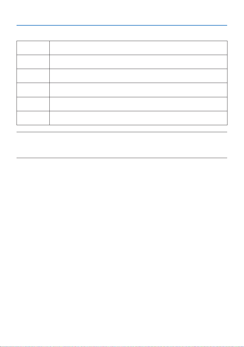
Option lens (sold separately)
3. Appendix
XP-57UL Motorized lens shift, Motorized zoom, Motorized focus
XP-58ZL Motorized lens shift, Motorized zoom, Motorized focus
XP-59ZL Motorized lens shift, Motorized zoom, Motorized focus
XP-60ZL Motorized lens shift, Motorized zoom, Motorized focus
XP-61ZL Motorized lens shift, Motorized zoom, Motorized focus
XP-62ZL Motorized lens shift, Motorized zoom, Motorized focus
(Throw ratio 0.31 - 0.33:1 F 2.05 - 2.11, f= 5.81 - 6.17 mm)
(Throw ratio 0.55 - 0.75:1 F 2.04 - 2.35, f= 10.03 - 13.60 mm)
(Throw ratio 0.74 - 1.08:1 F 2.02 - 2.33, f= 13.47 - 19.67 mm)
(Throw ratio 1.05 - 1.41:1 F 1.90 - 2.08, f= 8.78 - 25.30 mm)
(Throw ratio 1.40 - 2.11:1 F 1.80 - 2.11, f= 25.04 - 37.57 mm)
(Throw ratio 2.10 - 4.00:1 F 1.90 - 2.44, f= 37.23 - 70.60 mm)
NOTE:
• The above throw ratio is for projecting on 100" screen.
• The release date of XP-57UL and XP-58ZL is undecided.
Please refer to our website for release schedule.
35
Page 66
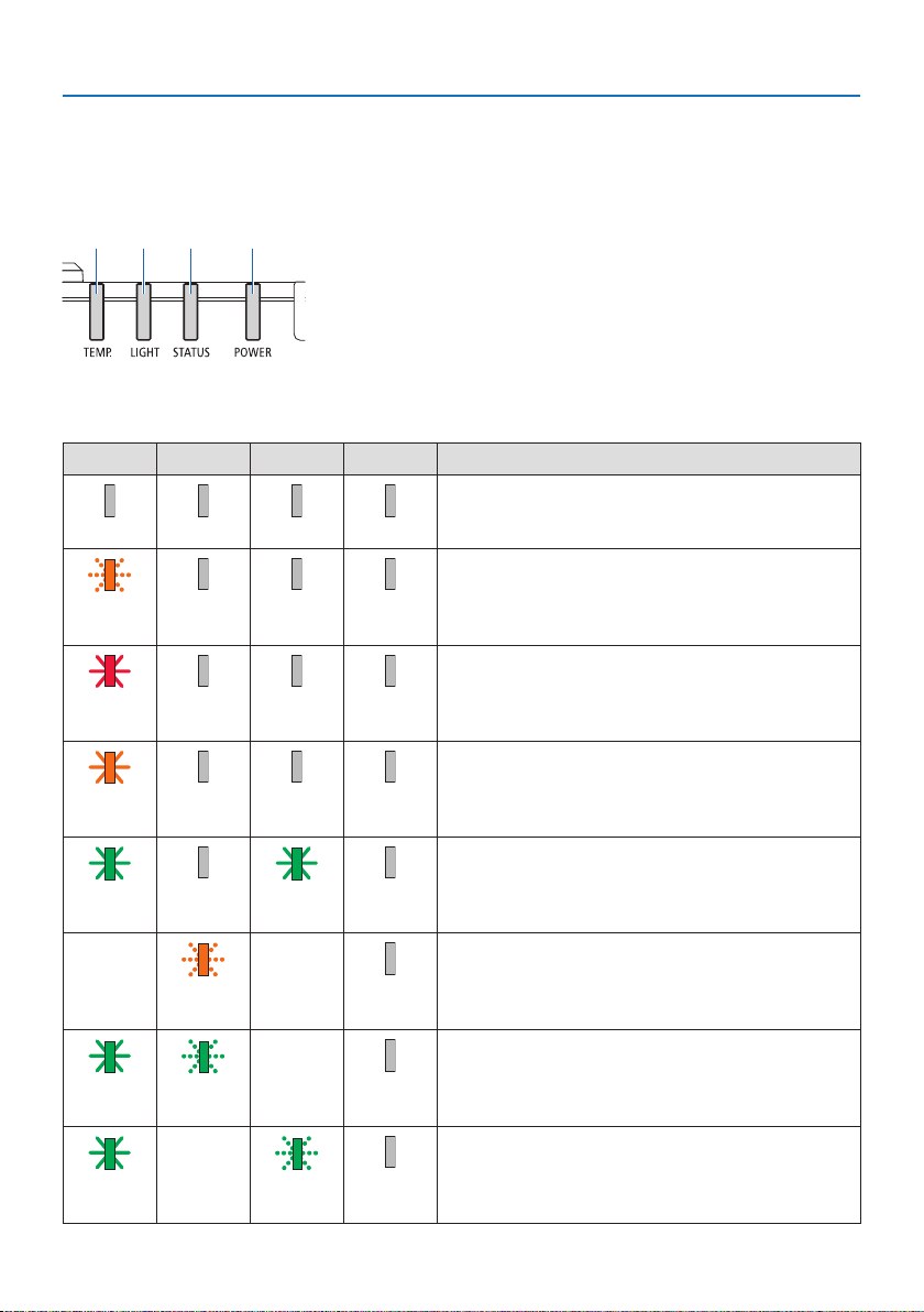
3. Appendix
3-2. Troubleshooting
This section helps you resolve problems you may encounter while setting up or using the projector.
Feature of each indicator
abcd
Indicator Message (Status message)
POWER STATUS LIGHT TEMP. Projector status
O O O O
Orange
(Blink*
1
)
O O O
a: POWER indicator
b: STATUS indicator
c: LIGHT indicator
d: TEMP. indicator
Power is o
Now switching to the standby mode
Main unit now cooling
In the state of Standby (Network is unavailable)
Red
(Light)
Orange
(Light)
Green
(Light)
Status varies Orange
Green
(Light)
Green
(Light)
O O O
O O O
O Green
(Blink*
Green
(Blink*2)
Status varies Green
(Light)
Status varies O
2
)
Status varies O
(Blink*3)
In the state of Standby (Network is available)
Powered state
O
[LENS CALIBRATION] implement request.
Performing the lens calibration
Shutter function is activating
O
36
Page 67

POWER STATUS LIGHT TEMP. Projector status
Preparing for powering [ON]
3. Appendix
Green
1
)
(Blink*
*1 Repetition to light on for 0.5 seconds / o for 0.5 seconds
*2 Repetition to light on for 0.5 seconds / o for 0.5 seconds / on for 0.5 seconds / o for 2 seconds
*3 Repetition to light on for 0.5 seconds / o for 5 seconds
O O O
37
Page 68
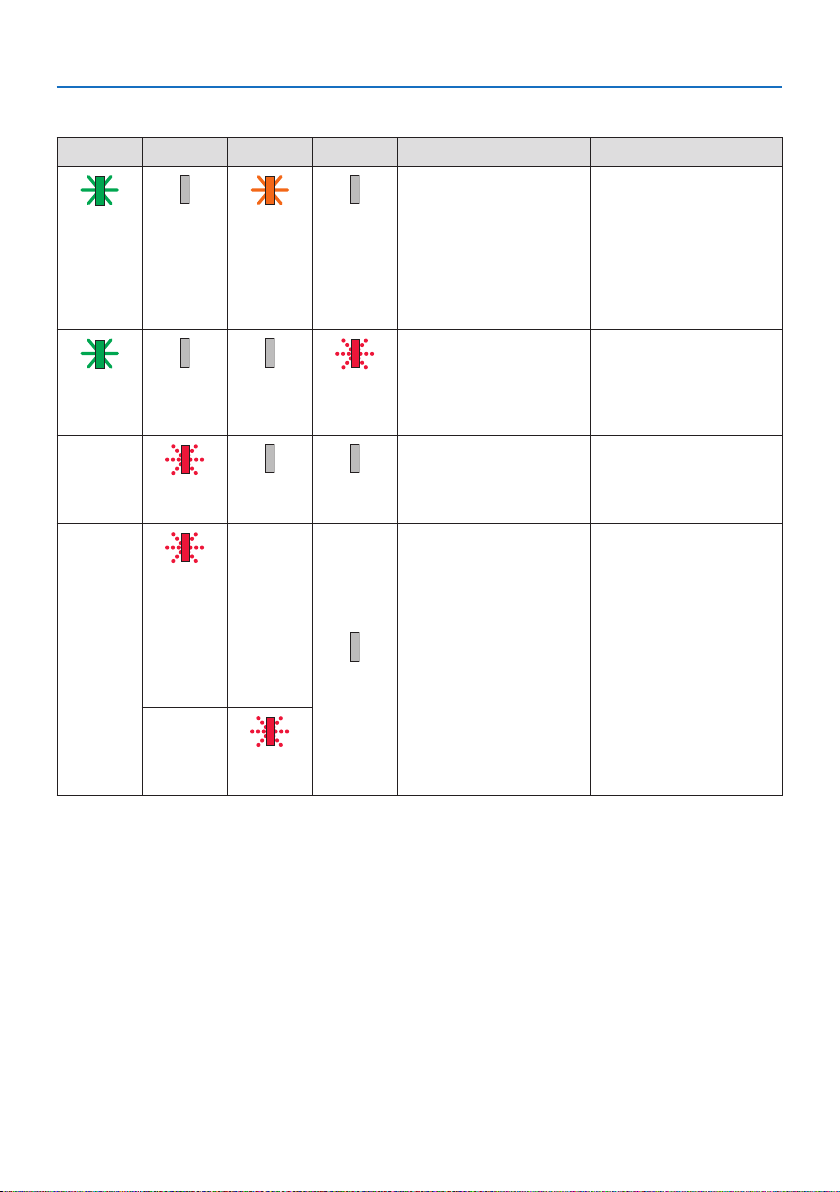
Indicator Message (Error message)
POWER STATUS LIGHT TEMP. Projector status Procedure
Green
O Orange
(Light)
Green
O O Red
(Light)
Status varies Red
(Blink*
Red
(ashing
other than
as describe
Status varies
above)
(lit)
Temperature problem Ambient temteprature
O
(Light)
Temperature problem Ambient temperature
1
)
(Blink*
Lens mounting error Lens is not mounted
4
)
O O
Error requiring service
support
Status varies
Or
O
is high. The projector's
protection functions will
activate depending on
the temperature of the
operating environment.
Lower the room temperature.
is out of the operation
temperature. Check if any
obstruction stays near the
exhaust vent.
properly. Mount it.
Contact your dealer or
service personnel. Make
sure to check and inform
indicator status for asking
to repair.
3. Appendix
Status varies Red
(Blink*2 *4)
*1 Repetition to light on for 0.5 seconds / o for 0.5 seconds
*2 Repetition to light on for 0.5 seconds / o for 0.5 seconds / on for 0.5 seconds / o for 2 seconds
*4 Repetition to light on for 0.5 seconds / o for 2 seconds
38
Page 69

3. Appendix
When the thermal protector is activated:
When inside temperature of the projector becomes too high or low, the TEMP. indicator start to
red blink in a short cycle. After this happened, the thermal protector will activate and the projector
may be turned o.
In this case, please take the below measures:
• Pull out the power plug from the wall inlet.
• Place the projector in cool place if it has been placed in high ambient temperature.
• Clean the exhaust vent if dust has accumulated on.
• Leave the projector for about one hour until inside temperature gets lower.
39
Page 70

Common Problems & Solutions
Problem Check These Items
Does not turn on or shut
down
Will turn o
No picture
Picture suddenly becomes
dark
Image isn’t square to the
screen
Picture is blurred
Image is scrolling vertically,
horizontally or both
• Check that the power cord is plugged in and that the power button on the projector cabinet or the
remote control is on.
• Check to see if the projector has temperature error, If projector inside temperature is too hot or cool,
it disabled to turn on the projector as the protection. Wait for a moment and try turn on the projector
again.
• In case it’s hard to think the trouble is not caused on the above mentioned conditions, unplug the
power cord from the outlet. Then wait 5 minutes before plugging it in again.
• Ensure that the [AUTO POWER OFF] is o.
• Check if the appropriate input is selected. If there is still no picture, press the INPUT button or one of
the input buttons again.
• Ensure your cables are connected properly.
• Use menus to adjust the brightness and contrast.
• Check that the SHUTTER CLOSE button is not pressed.
• Reset the settings or adjustments to factor y preset levels using the [RESET] in the Menu.
• If the HDMI input signal cannot be displayed, try the following.
Reinstall your driver for the graphics card built in your computer, or use the updated driver.
For reinstalling or updating your driver, refer to the user guide accompanied with your computer or
graphics card, or contact the support center for your computer manufacturer.
Install the updated driver or OS on your own responsibility.
We are not liable for any trouble and failure caused by this installation.
• The signal may not be supported depending on the HDBaseT transmission device. In addition, RS232C
interface may not be supported.
• If the projector is kept in sleep mode or other similar state, the temperature of the internal components could rise even when the projector is being used within its normal operating temperate. If the
power is ON when that occurs, the cooling fan will turn on and it will take a little bit of time before
the image is projected. Please wait for a while.
• A hot room may trigger the projector's protection functions, which can result in a temporary reduction
in luminance (brightness). Reduce the temperature in the room.
• Reposition the projector to improve its angle to the screen.
• Perform [GEOMETRIC CORRECTION] when the trapezoid is distorted.
• Adjust the focus.
• Reposition the projector to improve its angle to the screen.
• Ensure that the distance between the projector and screen is within the adjustment range of the
lens.
• Has the lens been shifted by an amount exceeding the guaranteed range?
• Condensation may form on the lens if the projector is cold, brought into a warm place and is then
turned on. Should this happen, let the projector stand until there is no condensation on the lens.
• Check the computer’s resolution and frequency. Make sure that the resolution you are trying to display
is supported by the projector.
3. Appendix
40
Page 71

Problem Check These Items
Remote control does not
work
On-screen menu is not
displayed
Indicator is lit or blinking
• Aim the remote control's infrared transmitter towards the projector's remote control receiver.
• Install new batteries.
• Make sure there are no obstacles between you and the projector.
• Stand within 7 m/276 inch of the projector.
• If a [CONTROL ID] has been set, check whether the ID number for the remote control matches the ID
number for the projector.
• Check whether On-screen mute is active.
On-screen mute can be turned o in the following ways:
- Press the OSD OPEN button while holding down the CTL button on the remote control.
• See the Indic ator Message.
For more information contact your dealer.
3. Appendix
41
Page 72
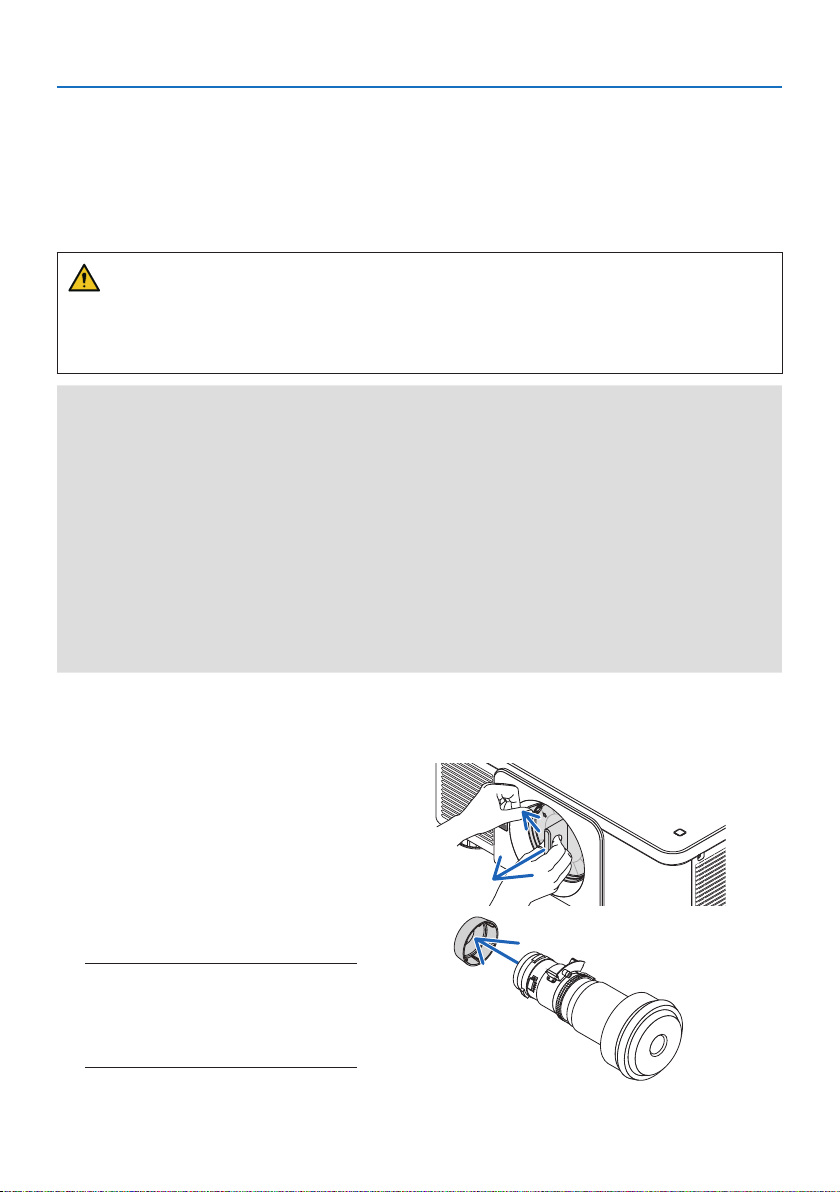
3. Appendix
3-3. Mounting a lens (sold separately)
Six separate bayonet style lenses can be used with this projector. The descriptions here are for the
XP-61ZL lens. Mount other lenses in the same manner.
After installing or replacing the lens unit, press the LENS CALIBRATION button on the projector to
carry out [LENS CALIBRATION]. By carrying out [LENS CALIBRATION], the lens unit and lens shift
adjustment range are calibrated.
WARNING:
(1) Turn o the power and wait for the cooling fan to stop, (2) disconnect the power cord and
wait for the unit to cool before mounting or removing the lens. Failure to do so can result in eye
injury, electric shock, or burn injuries.
Important:
• The projector and lenses are made of precision parts. Do not subject them to shock or excessive forces.
• Remove the separately sold lens when moving the projector. If not, the lens could be subject to shock while the projector is being
moved, damaging the lens and the lens shift mechanism.
• If the projector must be moved with the lens unit attached, such as when it is installed in a high or specic location, use the screws
included with the lens unit to secure it to the projector. Do not hold the lens when moving the projector.
• When dismounting the lens from the projector, return the lens position to the home position before turning o the power. Failure
to do so may prevent the lens from being mounted or dismounted because of narrow space between the projector and the lens.
• Never touch the lens surface while the projector is operating.
• Be very careful not to let dirt, grease, etc., on the lens surface and not to scratch the lens surface.
• Perform these operations on a at surface over a piece of cloth, etc., to prevent the lens from getting scratched.
• When leaving the lens o the projector for long periods of time, mount the dust cap on the projector to prevent dust or dirt from
getting inside.
Items to prepare
Ball point hexagon wrench driver (2.5 mm)
Mounting the lens
1. Remove the dust cap from the projector.
Push the tongue at the top left outward and pull the knob at the center
of the cap.
2. Remove the lens cap on the back of
the lens.
NOTE:
• Make sure to remove the lens cap at the unit
back side. If the lens unit with the lens cap
remaining on is installed on the projector, it
may cause of malfunction.
42
Page 73
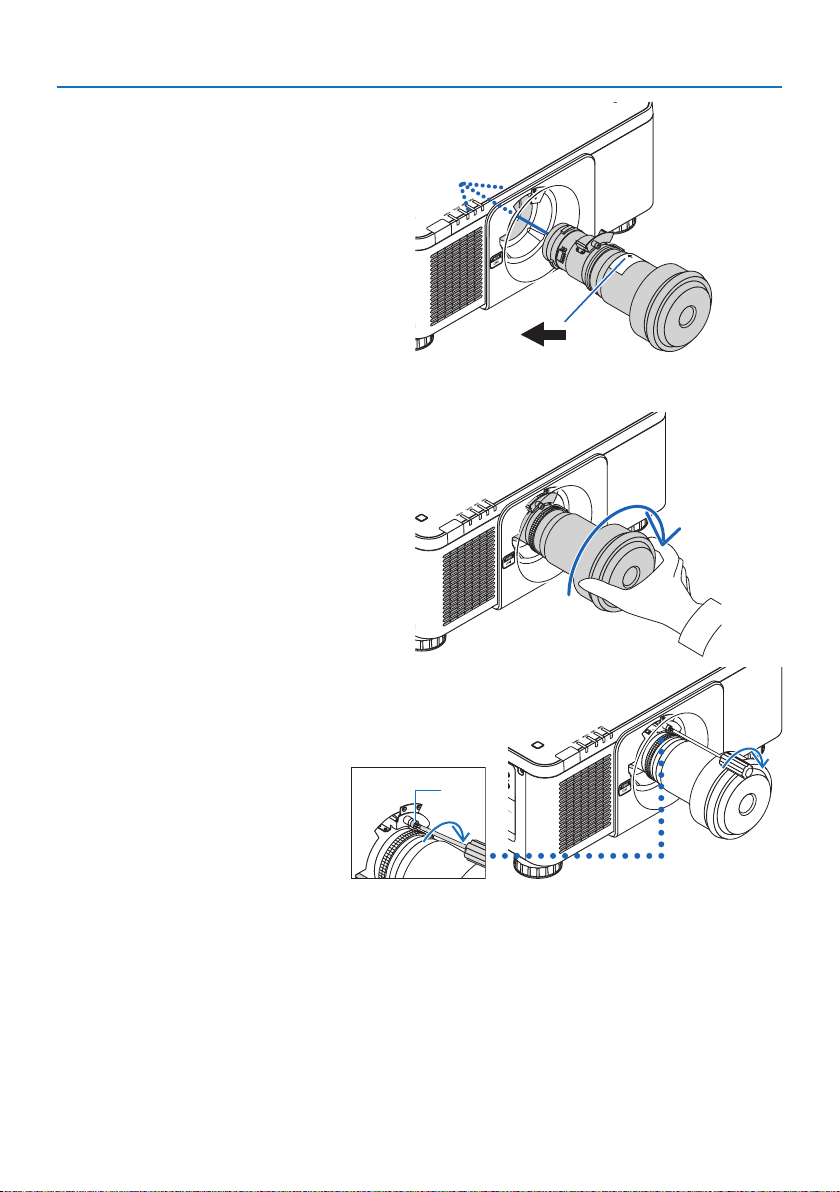
3. Hold the lens unit aligning the
labelled arrow on the unit coming
top and insert the unit to the projector.
Insert the lens slowly all the way in,
keeping the positioning slit at the
same angle.
4. Turn the lens unit rightward until
click is heard.
The lens is now fastened onto the
projector.
3. Appendix
a
a: Arrow mark
5. Use a ball point hexagon wrench
driver to turn lens unit screw ⓐ
clockwise to tighten.
a
43
Page 74
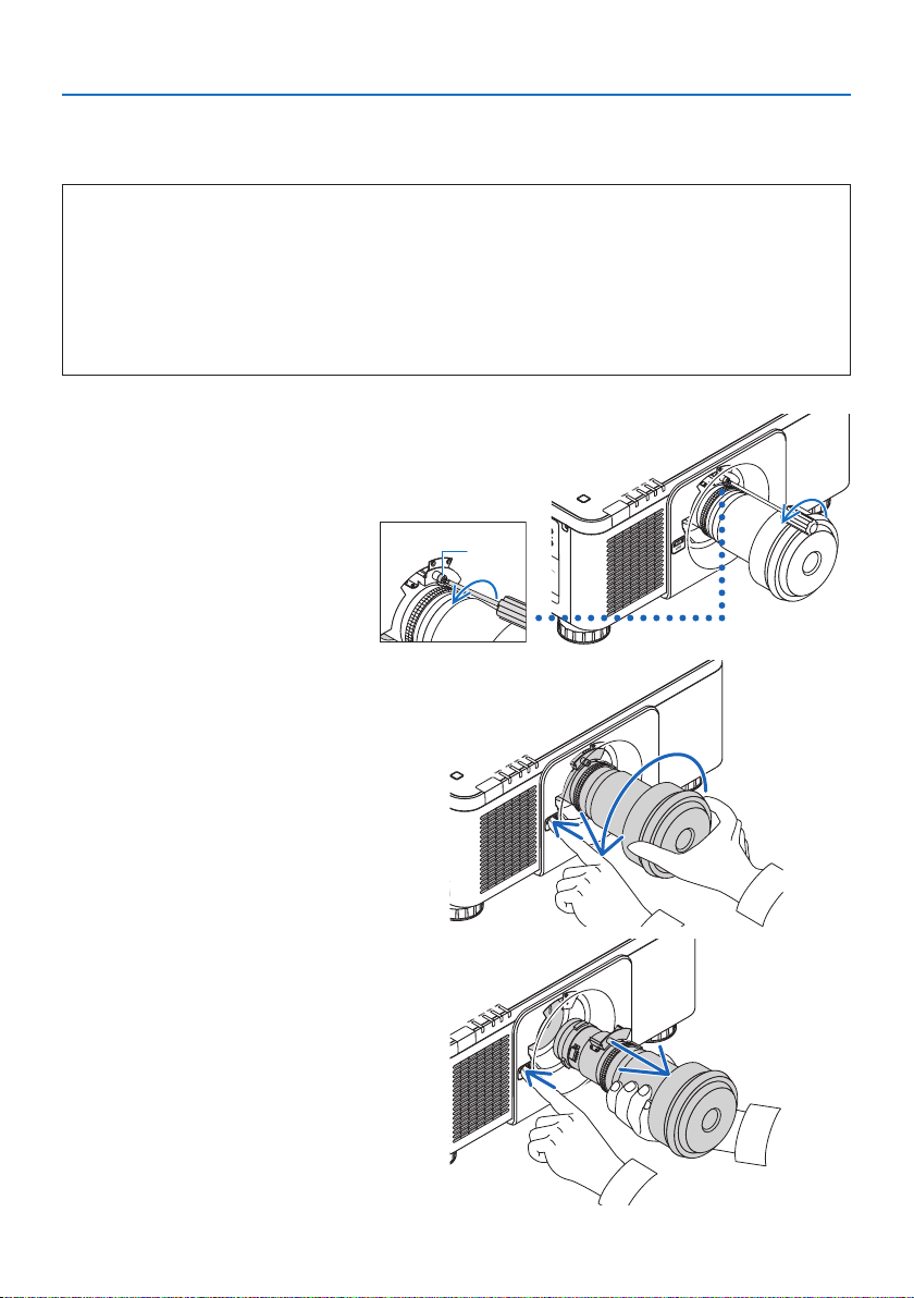
Removing the lens
Before removing the lens:
1. Turn on the projector and display an image.
2. Press the LENS CALIBRATION button.
The lens position will be moved to the home position.
3. Turn o the projector, and then unplug the power cord.
4. Mount the lens cap on the lens.
5. Wait until the projector cabinet is cool enough to handle.
1. To untighten, use a ball point
hexagon wrench driver to turn
the lens unit screw ⓐ counterclockwise until it rotates freely.
The screws cannot be removed.
a
2. While pressing the LENS release
button on the projector’s front
panel fully in, turn the lens counterclockwise.
The lens comes o.
3. Appendix
3. After slowly pulling the lens o
the projector, release the LENS
release button.
- After removing the lens, mount
the lens caps (front and back)
included with the lens before
storing the lens.
- If no lens is going to be mount-
ed on the projector, mount the
dust cap included with the
projector.
44
Page 75
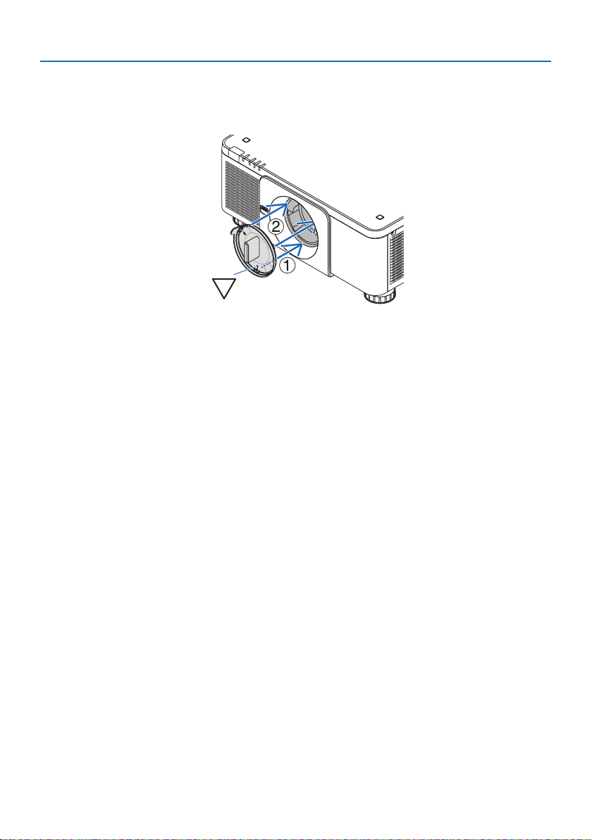
3. Appendix
To attach the dust cap to the projector, locate the catch on the lower end of the dust cap and place
it into the opening of the projector with the point of a triangle mark (▽) facing downward (① in
the gure below), and then push the upper end of the dust cap against the projector to place the
catches into the slot while clutching the handle (② in the gure below).
45
Page 76

Ver.2 2/25
 Loading...