

Page 1
Projector
P721Q-W/P601Q-W
User’s Manual
Model No.
XP-P721Q-W/XP-P601Q-W
Page 2

Table of Contents
IMPORTANT INFORMATION 4
Cable Information .........................................................................................................................................4
Notice Concerning Electromagnetic Interference (EMI) (For other regions) ...........................5
Disposing of Your Used Product ..............................................................................................................7
Laser Safety Caution .....................................................................................................................................9
Risk Groups ................................................................................................................................................... 10
Securing Personal Information .............................................................................................................. 10
About the Symbols .................................................................................................................................... 11
Safety Cautions ........................................................................................................................................... 12
Notes on Installation and Maintenance ............................................................................................. 22
Trademarks ...................................................................................................................................................26
INTRODUCTION 27
Package Overview ...................................................................................................................................... 27
Standard Accessories ................................................................................................................................ 27
Product Overview ...................................................................................................................................... 28
Connections ................................................................................................................................................. 31
Control Panel................................................................................................................................................32
Remote Control ........................................................................................................................................... 33
SETUP AND INSTALLATION 37
Connecting Sources to the Projector .................................................................................................. 37
Adjusting the Projector Image .............................................................................................................. 38
Adjusting the Projector’s Zoom and Focus ....................................................................................... 41
Adjusting the Projector Position ...........................................................................................................42
Remote Setup .............................................................................................................................................. 43
2
Page 3

USING THE PROJECTOR 45
Powering On / O the Projector ...........................................................................................................45
Menu Navigation and Features .............................................................................................................47
OSD Menu Tree............................................................................................................................................48
Image Menu ................................................................................................................................................. 59
Display Menu ............................................................................................................................................... 65
Communication Menu ............................................................................................................................. 71
System Menu ............................................................................................................................................... 83
Information Menu ...................................................................................................................................... 89
Language Menu .......................................................................................................................................... 92
ADDITIONAL INFORMATION 93
Compatible Resolutions ...........................................................................................................................93
RS232 Port Setting and Signals Connection .....................................................................................95
Image Size and Projection Distance .................................................................................................... 96
Ceiling Mount Installation .......................................................................................................................97
External Dimensions ................................................................................................................................. 98
Troubleshooting .........................................................................................................................................99
LED Indicators and Lightning Messages ..........................................................................................101
Specications .............................................................................................................................................102
RS232 Protocol Function List ...............................................................................................................105
REGISTER YOUR PROJECTOR! .............................................................................................................. 106
3
Page 4

IMPORTANT INFORMATION
Cable Information
Use shielded cables or cables attached ferrite cores so as not to interfere with radio and
television reception.
Supplier’s Declaration of Conformity
SHARP PROJECTOR, XP-P721Q-W / XP-P601Q-W
This device complies with Part 15 of the FCC Rules. Operation is subject to the
following two conditions: (1) This device may not cause harmful interference, and (2)
this device must accept any interference received, including interference that may
cause undesired operation.
Responsible Party:
SHARP ELECTRONICS CORPORATION
100 Paragon Drive, Montvale, NJ 07645
TEL: (630) 467-3000 www.sharpnecdisplays.us
WARNING:
FCC Regulations state that any unauthorized changes or modications to this
equipment not expressly approved by the manufacturer could void the user’s authority
to operate this equipment.
NOTE:
This equipment has been tested and found to comply with the limits for a Class A
digital device, pursuant to Part 15 of the FCC Rules. These limits are designed to provide
reasonable protection against harmful interference when the equipment is operated
in a commercial environment. This equipment generates, uses, and can radiate radio
frequency energy and, if not installed and used in accordance with the instruction
manual, may cause harmful interference to radio communications.
Operation of this equipment in a residential area is likely to cause harmful interference
in which case the user will be required to correct the interference at his own expense.
U.S.A. ONLY
4
Page 5

Notice Concerning Electromagnetic Interference (EMI) (For other regions)
WARNING:
Operation of this equipment in a residential environment could cause radio
interference.
(For Customers in U.K.)
IMPORTANT
• The wires in this mains lead are coloured in accordance with the following code:
GREEN-AND-YELLOW: “Earth”
BLUE: “Neutral”
BROWN: “Live”
• As the colours of the wires in the mains lead of this apparatus may not correspond
with the coloured markings identifying the terminals in your plug proceed as
follows:
• The wire which is coloured GREEN-AND-YELLOW must be connected to the
terminal in the plug which is marked by the letter E or by the safety earth symbol
or coloured green or green-and-yellow.
• The wire which is coloured BLUE must be connected to the terminal which is
marked with the letter N or coloured black.
• The wire which is coloured BROWN must be connected to the terminal which is
marked with the letter L or coloured red.
• Ensure that your equipment is connected correctly. If you are in any doubt consult
a qualied electrician.
“WARNING: THIS APPARATUS MUST BE EARTHED.”
5
Page 6
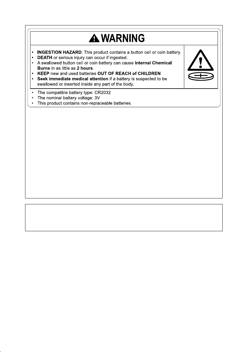
• Remove and immediately recycle or dispose of used batteries according to local
regulations and keep away from children. Do NOT dispose of batteries in household
trash or incinerate.
• Even used batteries may cause severe injury or death.
• Call a local poison control center for treatment information.
• The compatible battery type: CR2032
• The nominal battery voltage: 3V
• Non-rechargeable batteries are not to be recharged.
• Do not force discharge, recharge, disassemble, heat above 95°F (35°C) or incinerate.
Doing so may result in injury due to venting, leakage or explosion resulting in
chemical burns.
• This product contains non-replaceable batteries.
This product utilizes a CR coin Lithium battery which contains a Perchlorate material.
Special handling for this material may apply,
See www.dtsc.ca.gov/hazardouswaste/perchlorate.
6
Page 7

Disposing of Your Used Product
Information on the Disposal of this Equipment and its Batteries
IF YOU WISH TO DISPOSE OF THIS EQUIPMENT OR ITS BATTERIES, DO NOT USE THE
ORDINARY WASTE BIN, AND DO NOT PUT THEM INTO A FIREPLACE!
Used electrical and electronic equipment and batteries should always be collected and
treated SEPARATELY in accordance with local law.
Separate collection promotes an environment-friendly treatment, recycling of materials,
and minimizing nal disposal of waste. IMPROPER DISPOSAL can be harmful to human
health and the environment due to certain substances! Take USED EQUIPMENT to a
local, usually municipal, collection facility, where available.
Remove USED BATTERIES from equipment, and take them to a battery collection facilit y;
usually a place where new batteries are sold.
If in doubt about disposal, contact your local authorities or dealer and ask for the correct
method of disposal.
ONLY FOR USERS IN THE EUROPEAN UNION, AND SOME OTHER COUNTRIES;
FOR INSTANCE NORWAY AND SWITZERLAND: Your participation in separate collection
is requested by law.
The symbol shown above appears on electrical and electronic equipment and batteries
(or the packaging) to remind users of this. If ‘Hg’ or ‘Pb’ appears below the symbol, this
means that the battery contains traces of mercury (Hg) or lead (Pb), respectively.
Users from PRIVATE HOUSEHOLDS are requested to use existing return facilities for
used equipment and batteries.
Batteries are collected at points of sale. Return is free of charge.
If the equipment has been used for BUSINESS PURPOSES, please contact your dealer
who will inform you about take-back. You might be charged for the costs arising from
take-back. Small equipment (and small quantities) might be taken back by your local
collection facility. For Spain: Please contact the established collection system or your
local authority for take-back of your used products.
7
Page 8

Information on the Disposal of this Equipment and its Batteries
IF YOU WISH TO DISPOSE OF THIS EQUIPMENT, DO NOT USE THE ORDINARY WASTE BIN,
AND DO NOT PUT THEM INTO A FIREPLACE!
Used electrical and electronic equipment and batteries should always be collected and
treated SEPARATELY in accordance with local law.
Separate collection promotes an environment-friendly treatment, recycling of materials,
and minimizing nal disposal of waste. IMPROPER DISPOSAL can be harmful to human
health and the environment due to certain substances! Take USED EQUIPMENT to a
local, usually municipal, collection facility, where available.
This equipment contains a BATTERY which cannot be removed by the user. For battery
exchange, please contact your dealer.
If in doubt about disposal, contact your local authorities or dealer and ask for the correct
method of disposal.
ONLY FOR USERS IN THE EUROPEAN UNION, AND SOME OTHER COUNTRIES;
FOR INSTANCE NORWAY AND SWITZERLAND: Your participation in separate collection
is requested by law.
The symbol shown above appears on electrical and electronic equipment (or the
packaging) to remind the users of this.
Users from PRIVATE HOUSEHOLDS are requested to use existing return facilities for used
equipment. Return is free of charge.
If the equipment has been used for BUSINESS PURPOSES, please contact your dealer
who will inform you about take-back. You might be charged for the costs arising from
take-back. Small equipment (and small quantities) might be taken back by your local
collection facility. For Spain: Please contact the established collection system or your
local authority for take-back of your used products.
8
Page 9

Laser Safety Caution
WARNING
CLASS 1 LASER PRODUCT [IEC 60825-1:2014]
CLASS 1 CONSUMER LASER PRODUCT OF EN 60825-1:2014+A11:2021 (For EU and UK)
• The laser module is equipped in this product. Use of controls or adjustments of
procedures other than those specied herein may result in hazardous radiation
exposure.
Laser energy exposure near aperture may cause burns.
• This product is classied as Class 1 of IEC 60825-1:2014.
• For EU and UK, EN 60825-1:2014+A11:2021 and EN 50689:2021 are also conformed.
• Obey the laws and regulations of your country in relation to the installation and
management of the device.
For USA
Complies with 21 CFR 1040.10 and 1040.11 except for conformance as a Risk Group
2 LIP as dened in IEC 62471-5:Ed. 1.0. For more information see Laser Notice No. 57,
dated May 8, 2019.
WARNING
• Do not allow to look into the projector beam at any distance from the projector. An
adult should supervise the children to prevent exposure risks.
• Check that there is no one looking at the lens, when using the remote control for
starting the projector.
• Do not look at the projected light using optical devices(binoculars, telescopes,
magnifying glasses, reectors, etc).
• [ WARNING: MOUNT ABOVE THE HEADS OF CHILDREN. ]
The use of a ceiling mount is recommended with this product to place it above the
eyes of children.
• Outline of laser emitted from the built-in light module:
- Wave length: 455 nm
- Maximum power: 216W
Light Module
• A light module containing multiple laser diodes is equipped in the product as the
light source.
• These laser diodes are sealed in the light module. No maintenance or service is
required for the performance of the light module.
• End user is not allowed to replace the light module.
• Contact qualied distributor for light module replacement and further information.
9
Page 10

Risk Groups
This projector is classied as either IEC/EN 62471-5:2015 risk group 2.
Risk group 2 (RG2)
WARNING
As with any bright light source, do not stare into the beam, RG2 IEC/EN 62471-5:2015.
To the dealer and the installer
1. To prevent the projector from falling, install it on the ceiling in a way with sucient
strength to withstand the combined weight of the projector and the ceiling mount
unit for an extended period of time.
2. When installing the projector on the ceiling, be sure to do so correctly in accordance
with the installation manual for the Ceiling Mount Unit. Be sure to use the xed metal
ttings and to tighten the screws securely.
3. To prevent the projector from falling, use fall prevention wires.
• Use commercially available metal ttings to join the robust part of a building or
construction and the security bar of the projector with the fall prevention wires.
• Use commercially available metal ttings and fall prevention wires that have
sucient strength to withstand the combined weight of the projector and the
ceiling mount unit.
• Slightly slack o the fall prevention wires so as not to put a load on the projector.
• Refer to the “Product Overview” for the location of the security bar. Please refer
page 28 for details.
(for Germany only)
Machine Noise Information Regulation - 3. GPSGV,
The highest sound pressure level is less than 70 dB (A) in accordance with EN ISO 7779.
Information of the AUDIO OUT mini jack
The AUDIO OUT mini jack does not support earphone/headphone terminal.
Securing Personal Information
Personally identiable information, such as IP addresses, may be saved on the projector.
Before transferring or disposing of the projector, clear this data by performing [System] →
[Reset] → [Reset All] on the on-screen menu.
10
Page 11

About the Symbols
To ensure safe and proper use of the product, this manual uses a number of symbols to
prevent injury to you and others as well as damage to property.
The symbols and their meanings are described below. Be sure to understand them
thoroughly before reading this manual.
Failing to heed this symbol and handling the product
WARNING
CAUTION
Examples of symbols
This symbol indicates you should be careful of electric shocks.
This symbol indicates you should be careful of high temperatures.
This symbol indicates something that must be prohibited.
This symbol indicates something that must not be got wet.
erroneously could result in accidents leading to death or
major injury.
Failing to heed this symbol and handling the product
erroneously could result in personal injury or damage to
surrounding property.
This symbol indicates you should not touch with wet hands.
This symbol indicates something that must not be disassembled.
This symbol indicates things you must do.
This symbol indicates that the power cord should be unplugged from the
power outlet.
11
Page 12
Safety Cautions
Projected light
Projected light and the pictogram/label indicated on the
cabinet
• Do not look into the projector’s lens.
• Strong light that could damage your vision is projected when the
PROHIBITED
projector is operating. Laser energy exposure near aperture may
cause burns. Be especially careful when children are around.
• Do not look at the projected light using optical devices (magnifying
glasses, reectors, etc.). Doing so could result in vision impairment.
• Check that there is no one looking at the lens within the projection
range before turning on the projector.
• Do not allow children to operate the projector alone. When a child is
operating the projector an adult should always be present and watch
the child carefully.
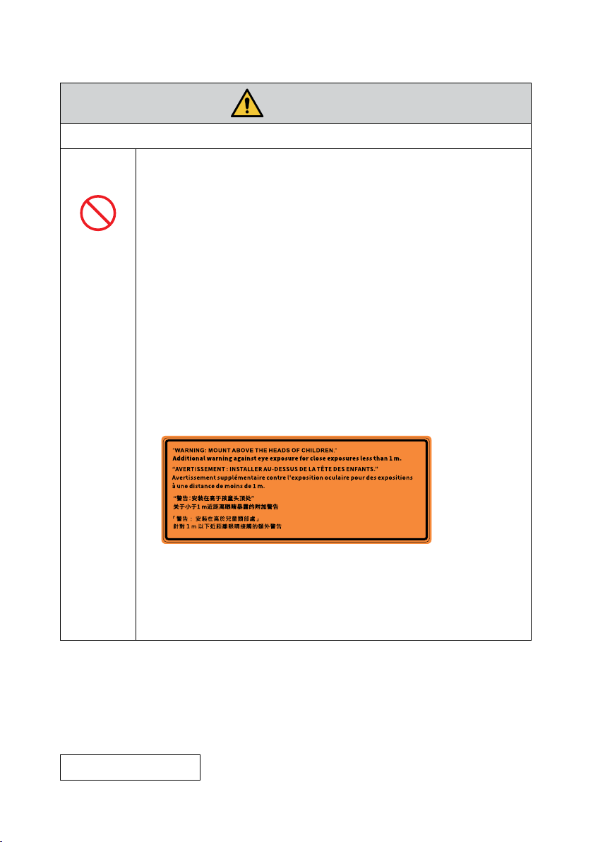
• The following labels are stuck on the projector.
Label 1
FDA additional warning label (For USA only)
WARNING
“WARNING: MOUNT ABOVE THE REACH AND SIGHT OF CHILDREN.”
The use of a ceiling mount is recommended with this product to
place it above the eye level of children.
Additional warning against eye exposure for close exposures less
than 1 m.
Continue to next page
12
Page 13
WARNING
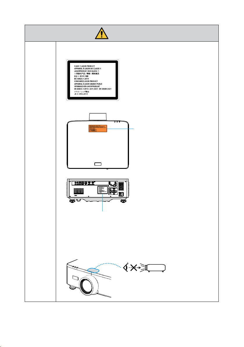
Label 2
Laser explanatory label
Label Location
Label 1
(For USA only)
Label 2
• This product is classied as RG2 of IEC/EN 62471-5:2015.
• The below pictogram, that is indicated near the lens on the cabinet,
describes this projector is categorized in the risk group 2 of IEC/EN
62471-5:2015. As with any bright light source, do not stare into the
beam, RG2 IEC/EN 62471-5:2015.
RG 2
13
Page 14
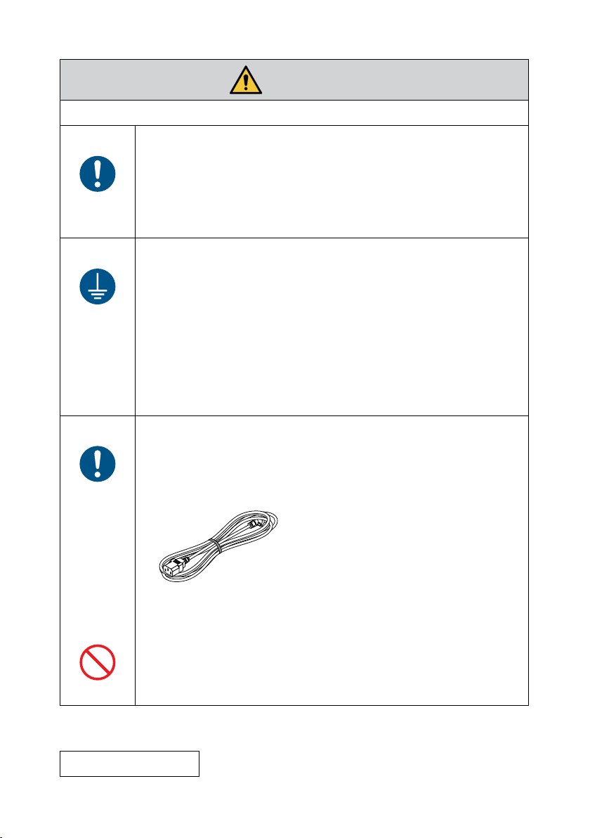
Power supply
Use a suitable voltage power supply.
• This projector is designed to be used with a 100–240 VAC, 50/60 Hz
REQUIRED
MUST BE
EARTHED
REQUIRED
• Use a power outlet as the projector’s power supply. Do not connect
Connecting the power cord to earth
• This equipment is designed to be used in the condition of the power
• Be sure to connect the projector and the computer (signal source)
Handling the power cord
• Please use the power cord supplied with this projector. If the
WARNING
power supply. Before using the projector, check that the power supply
to which the projector is to be connected meets these requirements.
the projector directly to electrical light wiring. Doing so is dangerous.
cord connected to earth. If the power cord is not connected to the
earth, it may cause electric shock. Please make sure the power cord is
connected to the wall outlet directly and earthed properly.
Do not use a 2-pin plug converter adapter.
to the same earth point. If the projector and the computer (signal
source) will be connected to dierent earth points, uctuations in
the earth potential may cause re or smoke.
supplied power cord does not satisfy requirements of your country’s
safety standard, and voltage and current for your region, make sure
to use the power cord that conforms to and satises them.
• The power cord you use must be
approved by and comply with the safety
standards of your country.
Please refer to the page 103 about the
power cord specication.
• For selecting an appropriate power
cord, please check rated voltage for your
region by yourself.
• The power cord included with this projector is exclusively for use
with this projector. For safety, do not use it with other devices.
PROHIBITED
Continue to next page
14
Page 15
HAZARDOUS
VOLTAGE
DO NOT TOUCH
WITH WET
HANDS
Installation
PROHIBITED
WARNING
• Handle the power cord with care. Damaging the cord could lead to
re or electric shock.
- Do not place heavy objects on the cord.
Do not place the cord under the projector.
-
- Do not cover the cord with a rug, etc.
-
Do not scratch or modify the cord.
Do not bend, twist or pull the cord with excessive force.
-
-
Do not apply heat to the cord.
Should the cord be damaged (exposed core wires, broken wires,
etc.), ask your dealer to replace it.
• Do not touch the power plug should you hear thunder. Doing so
could result in electric shock.
• Do not connect or disconnect the power cord with wet hands. Doing
so could result in electric shock.
Do not use in places such as those described below.
• Do not use in places such as those described below. Doing so could
lead to re or electric shock.
- Shaky tables, inclined surfaces or other unstable places.
- Poorly ventilated spaces.
- Near a radiator, other heat sources, or in direct sunshine.
- Continual vibration areas.
- Humid, dusty, steamy, or oily areas.
- An environment where there are corrosive gases (sulfur dioxide,
hydrogen sulde, nitrogen dioxide, chlorine, ammonia, ozone, etc.).
- Outdoors.
- High-temperature environment where humidity changes rapidly
and condensation is likely to occur.
Continue to next page
15
Page 16
DO NOT WET
UNPLUG THE
POWER CORD
CAUTION
WARNING
• Do not use in places such as those described below where the
projector could get wet. Doing so could lead to re or electric shock.
- Do not use in the rain or snow, on a seashore or waterfront, etc.
- Do not use in a bathroom or shower room.
- Do not install under equipment that discharges water, such as air
conditioners.
- Do not place vases or potted plants on the projector.
- Do not place cups, cosmetics or medicines on the projector.
Should water, etc. get inside the projector, rst turn o the
projector’s power, then unplug the power cord from the power
outlet and contact your dealer.
Installing suspended from the ceiling
• Consult your dealer for installing the projector on the ceiling. Special
skills are required for ceiling installation.
DO NOT perform installation work by people other than installers.
Doing so may result in the projector falling and causing injury.
• We are not liable for any accident or/and damage resulting from
improper installation or handling, misuse, modication, or natural
disasters.
• When installed suspended from the ceiling, etc. do not hang from
the projector. The projector could drop and cause injury.
• When installing suspended from the ceiling, use a power outlet
that is within reach so the power cord can be easily plugged and
unplugged.
On use
PROHIBITED
UNPLUG THE
POWER CORD
Do not place objects inside the projector.
• Do not insert or drop metal or combustible objects or other foreign
materials into the projector from the vents. Doing so could lead to
re or electric shock. Be particularly careful if there are children in the
home. Should a foreign object get inside the projector, rst turn o
the projector’s power, then unplug the power cord from the power
outlet and contact your dealer.
16
Page 17
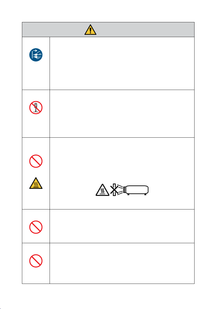
UNPLUG THE
POWER CORD
DO NOT
DISASSEMBLE
PROHIBITED
WARNING
Unplug the power cord if the projector malfunctions.
• Should the projector emit smoke or strange odors or sounds, or
if the projector has been dropped or the cabinet broken, turn o
the projector’s power, then unplug the power cord from the power
outlet. Otherwise it may cause not only re or electric shock but also
serious damage to your eyesight or burns. Contact your dealer for
repairs.
Never try to repair the projector on your own. Doing so is dangerous.
Do not disassemble the projector.
• Do not remove or open the projector’s cabinet.
Also, do not modify the projector. There are high voltage areas in
the projector. It may cause re, electric shock, or laser light leakage,
resulting in serious damage to your eyesight or burns.
Have qualied service personnel perform inspection, adjustments
and repairs of the interior.
Do not place objects in front of the lens while the projector is
operating.
• Do not place objects in front of the lens that obstruct the light while
the projector is operating. The object could get hot and be broken or
catch re.
• The below pictogram indicated on the cabinet means the precaution
for avoiding to place objects in front of the projector lens.
CAUTION
FOR HIGH
TEMPERATURE
PROHIBITED
PROHIBITED
When cleaning the projector
• Do not use ammable gas sprays to remove dust from the lens,
cabinet, etc. Doing so could lead to re.
Do not use in high security locations.
• Usage of the product must not be accompanied by fatal risks or
dangers that, could lead directly to death, personal injury, severe
physical damage or other loss, including nuclear reaction control
in nuclear facility, medical life support system, and missile launch
control in a weapon system.
17
Page 18
Power cord
REQUIRED
REQUIRED
UNPLUG THE
POWER CORD
CAUTION
Handling the power cord
• The projector should be installed close to an easily accessible power
outlet.
• When connecting the power cord to the projector’s AC IN terminal,
make sure the connector is fully and rmly inserted. Loose
connection of the power cord could lead to re or electric shock.
Handling the power cord by following below to avoid re or
electric shock
• When connecting or disconnecting the power cord, pull the power
cord out by holding onto its plug.
• Unplug the power cord from the power outlet before cleaning the
product or when not planning to use the product for an extended
time.
• When the power cord or plug is heat or damaged, unplug the power
cord from the power outlet, and contact your dealer.
Periodically clean dust and other debris from the power plug
• Failure to do so could result in re or electric shock.
REQUIRED
REQUIRED
PROHIBITED
Disconnect power cords and other cables before moving the
projector
• Before moving the product, make sure the product power is o, then
unplug the power cord from the power outlet and check that all
cables connecting the product to other devices are disconnected.
Do not use the power cord with a power tap
• Adding an extension cord may lead to re as a result of overheating.
18
Page 19
On use
PROHIBITED
REQUIRED
PROHIBITED
CAUTION
Do not use on networks subject to overvoltage.
• Connect the projector’s HDBaseT port and LAN port to a network for
which there is no risk of overvoltage being applied.
Overvoltage applied to the HDBaseT or LAN port could result in
electric shock.
Lens shift, focus and zoom operations
• When shifting the lens or adjusting the focus or zoom, do so
from either behind or the side of the projector. If adjustments are
performed from the front, your eyes could be exposed to strong light
and get injured.
Handling batteries
Incorrect usage of batteries can result in leaks or bursting.
• Use the specied batteries only.
• Insert batteries matching the (+) and (–) signs on each battery to the
(+) and (–) signs of the battery compartment.
• Do not mix battery brands.
• Do not combine new and old batteries. This can shorten battery life
or cause liquid leakage of batteries.
• Remove dead batteries immediately to prevent battery acid from
leaking into the battery compartment.
If leaked battery uid gets on your skin or clothing, rinse
immediately and thoroughly. If it gets into your eye, bathe your eye
well rather than rubbing and seek medical treatment immediately.
Leaked battery uid that gets into your eye or your clothing may
cause a skin irritation or damage your eye.
• If you will not use the remote control for a long time, remove the
batteries.
• Leaving a battery in an extremely high temperature surrounding
environment, or a battery subject to extremely low air pressure, that
can result in an explosion or the leakage of ammable liquid or gas.
• Properly dispose of depleted batteries. Disposal of a battery into
water, re, or a hot oven, or mechanically crushing, cutting, or
modifying a battery can result in an explosion.
• Do not short-circuit the batteries.
• Do not charge the batteries. The batteries provided are not
rechargeable.
• Contact your dealer or local authorities when disposing of batteries.
19
Page 20
PROHIBITED
CAUTION
FOR HIGH
TEMPERATURE
PROHIBITED
CAUTION
About the vents
• Do not obstruct the projector’s vents. Also, do not place such soft
objects as paper or cloths underneath the projector. Doing so could
lead to re.
Leave sucient space between the place where the projector is
installed and its surroundings.
• Do not touch the exhaust vent area while projecting or immediately
after projecting images. The exhaust vent area may be hot at this
time and touching it could cause burns.
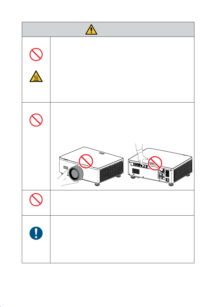
Moving the projector
• When moving the projector, do not hold the lens hood. The lens
hood could become loose and the main unit could fall down,
causing injuries.
• Do not put your hand into the recess of the connection terminal. The
projector could be damaged or fall down, resulting in injuries.
PROHIBITED
REQUIRED
Do not push or climb on the product. Do not grab or hang onto the
product. Do not rub or tap the product with hard objects. The product
may fall, causing damage to the product or personal injury.
Avoid locations with extreme temperatures and humidity
• Failure to do so could lead to re or electric shock or damage to the
projector. The usage environment for this projector is as follows:
- The operating temperature: 0°C to 45°C / 32°F to 113°F /
humidity: 10 to 85% (without condensation)
- The storage temperature: -10°C to 60°C / 14°F to 140°F /
humidity: 20 to 90% (without condensation)
20
Page 21
Inspections and Cleaning
Inspecting the projector and cleaning the inside
• Consult with your dealer about once per year for cleaning of the
inside of the projector. Dust could accumulate inside of the projector
REQUIRED
if it is not cleaned for extended periods of time, leading to res or
malfunction.
3D
Health precautions to users viewing 3D images
Before viewing, be sure to read health care precautions that may be
found in the user’s manual included with your 3D eyeglasses or your 3D
REQUIRED
compatible content such as Blu-ray Discs, video games, computer’s video
les and the like.
To avoid any adverse symptoms, heed the following:
• Do not use 3D eyeglasses for viewing any material other than 3D
images.
• Allow a distance of 2 m/7 feet or greater between the screen and a
user. Viewing 3D images from too close a distance can strain your
eyes.
• Avoid viewing 3D images for a prolonged period of time. Take a
break of 15 minutes or longer after every hour of viewing.
• If you or any member of your family has a history of light-sensitive
seizures, consult a doctor before viewing 3D images.
• While viewing 3D images, if you get sick such as nausea, dizziness,
queasiness, headache, eyestrain, blurry vision, convulsions, and
numbness, stop viewing them. If symptoms still persist, consult a
doctor.
• View 3D images from the front of the screen. Viewing from an angle
may cause fatigue or eyestrain.
CAUTION
21
Page 22
Notes on Installation and Maintenance
Do not install or store in such places as those described below.
• Locations that amplify vibrations and impacts
If installed in places where the vibrations from power sources and the like are
conveyed, or in vehicles or on vessels, etc. the projector could be aected by
vibrations or shocks that may damage internal parts and lead to malfunction.
• Close to high voltage power lines and power sources
It could disrupt the unit.
• Places where strong magnetic elds are generated
Doing so could lead to malfunction.
• Outdoors and places with humid or dust
Places exposed to oil smoke or steam
Places where corrosive gases are generated
Attached substances such as oil, chemicals and moisture may cause deformation or
cracks of the cabinet, corrosion of the metal parts, or malfunction.
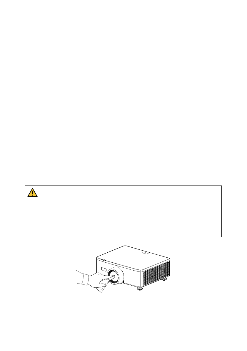
Cleaning the Lens
• The projector has a glass lens. Use a commercially available glass lens cleaner.
• Do not scratch or mar the lens surface as a glass lens is easily scratched.
• Never use alcohol or glass lens cleaner as doing so will cause damage to the glass lens
surface.
WARNING
• Do not use a spray containing ammable gas to remove dust attached to the lens,
etc. Doing so may result in re.
• Turn o the power and unplug the power plug from the socket for cleaning. If the
unit turns on while cleaning the lens, the strong light from the lens could damage
your eyes. It could also burn your ngers.
22
Page 23
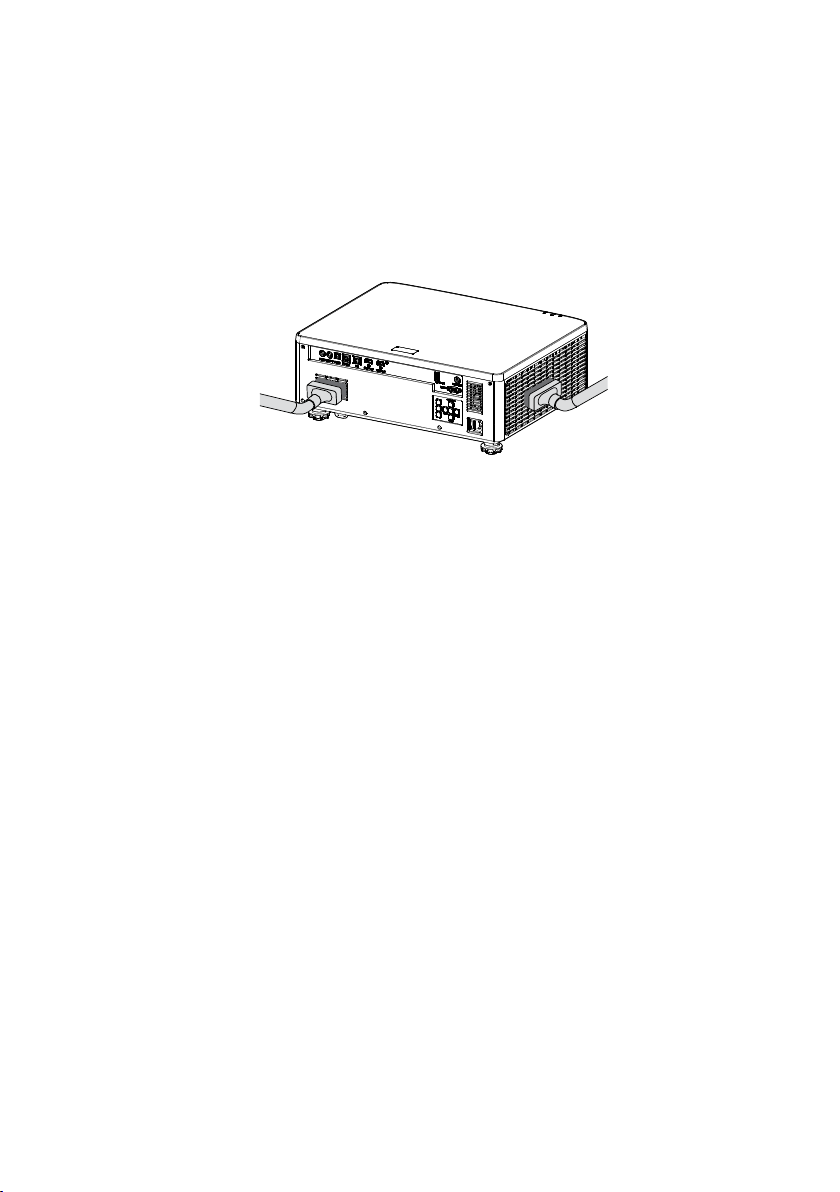
Cleaning the Cabinet
Turn o the projector, and unplug the projector before cleaning.
• Use a dry soft cloth to wipe dust o the cabinet.
If heavily soiled, use a mild detergent.
• Never use strong detergents or solvents such as alcohol or thinner.
• When cleaning the ventilation slits or the speaker using a vacuum cleaner, do not
force the brush of the vacuum cleaner into the slits of the cabinet.
Vacuum the dust o the ventilation slits or the speaker.
• Poor ventilation caused by dust accumulation in ventilation openings can result in
overheating and malfunction. These areas should be cleaned regularly.
• Do not scratch or hit the cabinet with your ngers or any hard objects.
• Contact your dealer for cleaning the inside of the projector.
Note: Do not apply volatile agent such as insecticide on the cabinet, the lens, or the screen.
Do not leave a rubber or vinyl product in prolonged contact with it. Otherwise the
surface nish will be deteriorated or the coating may be stripped o.
23
Page 24

Cautions for ensuring the projector’s performance
• If intense light like laser beams enters from the lens, it could lead to malfunction.
• Consult your dealer before using in places where much cigarette smoke or dust is
present.
• This unit has a built-in air pressure sensor, and the “High Altitude Mode “ will
automatically switch to “On” depending on the altitude of the installation location.
When the High Altitude Mode is switched to On, the cooling fan will rotate at high
speed.
• If the High Altitude Mode does not switch to On even when the altitude exceeds
1500 m/5000 ft, manually switch “System” “High Altitude” in the on-screen menu to
“ On”.
• When the projector is used at high altitudes (places where the atmospheric pressure
is low), it may be necessary to replace the optical parts sooner than usual.
• About moving the projector
Do not subject the projector to vibrations or strong shocks. The projector could be
damaged otherwise.
• Do not use the tilt feet for purposes other than adjusting the projector’s tilt.
Improper handling, such as carrying the projector by the tilt feet or using it leaned
against a wall, could lead to malfunction.
• The projector does not support stack installation. Do not stack projectors directly on
top of each other. Failure to do so may cause damage or failure.
• Do not touch the surface of the projection lens with bare hands.
Fingerprints or dirt on the surface of the projection lens will be enlarged and
projected on the screen. Do not touch the surface of the projection lens.
• Do not unplug the power cord from the projector or the power outlet while
projecting. It could lead to malfunction.
• About handling of the remote control
- The remote control will not work if the projector’s remote signal sensor or the
remote control’s signal transmitter is exposed to strong light or if there are obstacles
between them that obstruct the signals.
- Operate the remote control from within 6 meters (19.7 feet) from the projector,
pointing it at the projector’s remote signal sensor.
- Do not drop the remote control or handle it improperly.
- Do not let water or other liquids get on the remote control. Should the remote
control get wet, wipe it o immediately.
- Avoid using in hot and humid places as far as possible.
• Take measures to prevent external light from shining on the screen.
Make sure only the light from the projector shines on the screen. The less external
light on the screen, the higher the contrast and the more beautiful the images.
• About screens
Images will not be clear if there is dirt, scratches, discoloration, etc. on your screen.
Handle the screen with care, protecting it from volatile substances, scratches and dirt.
24
Page 25
• About Copyright of original projected pictures
Please note that using this projector for the purpose of commercial gain or the
attraction of public attention in a venue such as a coee shop or hotel and employing
compression or expansion of the screen image with the following functions may raise
concern about the infringement of copyrights which are protected by copyright law.
[Aspect Ratio], [V Keystone / H Keystone], Magnifying feature and other similar
features.
Power management function
The projector has power management functions. To reduce power consumption, the power
management functions (1 and 2) are factory preset as shown below. To control the projector
from an external device via a LAN or serial cable connection, use the on-screen menu to
change the settings for 1 and 2.
1. STANDBY MODE (Factory preset: Normal Standby)
To control the projector from an external device, select [Network Standby] or [Sleep]
for [Standby Mode].
( User’s manual: page 83)
2. AUTO POWER OFF (Factory preset: 20 minutes)
To control the projector from an external device, select [0] for [Auto Power O
(min)].
( User’s manual: page 84)
25
Page 26

Trademarks
• The terms HDMI, HDMI High-Denition Multimedia Interface, HDMI Trade dress
and the HDMI Logos are trademarks or registered trademarks of HDMI Licensing
Administrator, Inc.
• HDBaseT3 logo are trademarks of the HDBaseT Alliance.
• DLP®, the DLP logo and the DLP Link are trademarks or registered trademarks of Texas
Instruments in the United States and other countries.
• Trademark PJLink is a trademark applied for trademark rights in Japan, the United
States of America and other countries and areas.
• Blu-ray is a trademark of Blu-ray Disc Association.
• Crestron is a registered trademark of Crestron Electronics, Inc. of the United States.
• AMX is a registered trademark of AMX LLC of the United States.
• Ethernet is either a registered trademark or trademark of FUJIFILM Business
Innovation Corporation.
• GPL/LGPL Software Licenses
The product includes software licensed under GNU General Public License (GPL),
GNU Lesser General Public License (LGPL), and others.
For more information on each software, visit our web site.
https://www.sharp-nec-displays.com/dl/en/pj_manual/lineup.html
• Other product and company names mentioned in this user’s manual may be the
trademarks or registered trademarks of their respective holders.
26
Page 27
INTRODUCTION
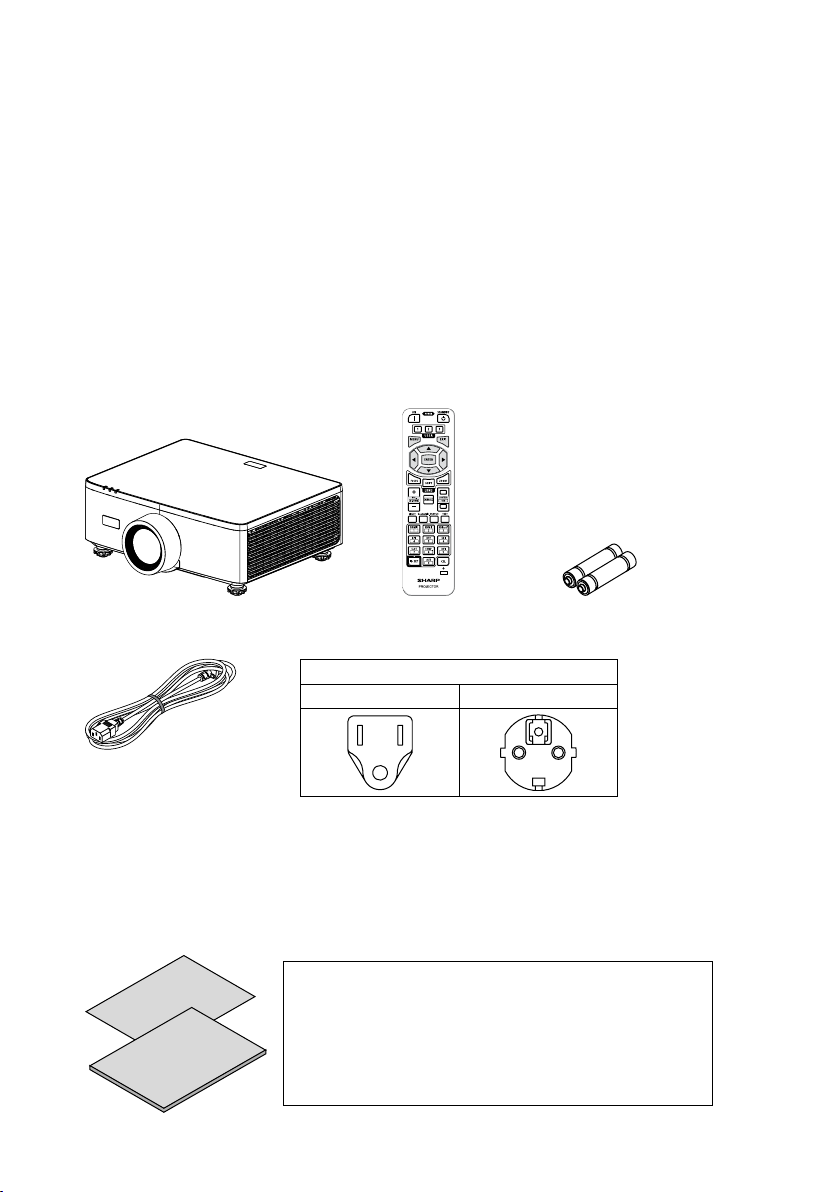
Package Overview
Carefully unpack and verify that you have the items listed below under standard
accessories. Some of the items under optional accessories may not be available
depending on the model, specication and your region of purchase. Please check with
your place of purchase. Some accessories may vary from region to region.
The warranty card is only supplied in some specic regions. Please consult your dealer for
detailed information.
Standard Accessories
Projector
X
Remote control AAA Manganese
batteries (x2)
Plug type
For USA For EU
Power cord
Documents
• Important Information
(For North America: TINS-0035VW01)
(For Other countries than North America: TINS-0035VW01 and TINS-0036VW01)
• Quick Setup Guide (TINS-0037VW01)
• Security Sticker (Use this sticker when security password is set on.)
For North America only
Limited warranty
For customers in Europe
You will nd our current valid Guarantee Policy on our
Web Site:
https://www.sharpnecdisplays.eu
27
Page 28
INTRODUCTION
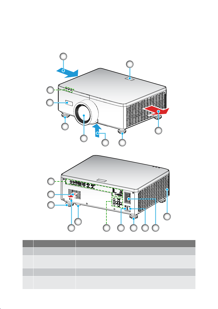
Product Overview
1
2
3
3
4
5
1
7
6
4
8
4
4
1210911 13
No. Item Function
1. Ventilation (Inlet) Take in outside air to cool the unit.
2. LED Indicators
The indicator light turns on or blinks to relay the status of
the projector.
3. IR Receivers Receive signals from the remote control.
Tilt-Adjustment
4.
Feet
Rotate the tilt feet to adjust the projector’s height.
6
13
28
Page 29
INTRODUCTION
No. Item Function
5. Lens Images are projected from here.
6. Ventilation (Outlet) Heated air is exhausted from here.
7. Input / Output Connect the cables for the various audio and video signals.
This is used when attaching an anti-theft cable.
TIP:
8.
Security Slot (
9. Security Bar
10. Control Panel
11. Main Power Switch Turn on and o the power supply.
12. AC Inlet
13. Speaker Emit sound.
Note:
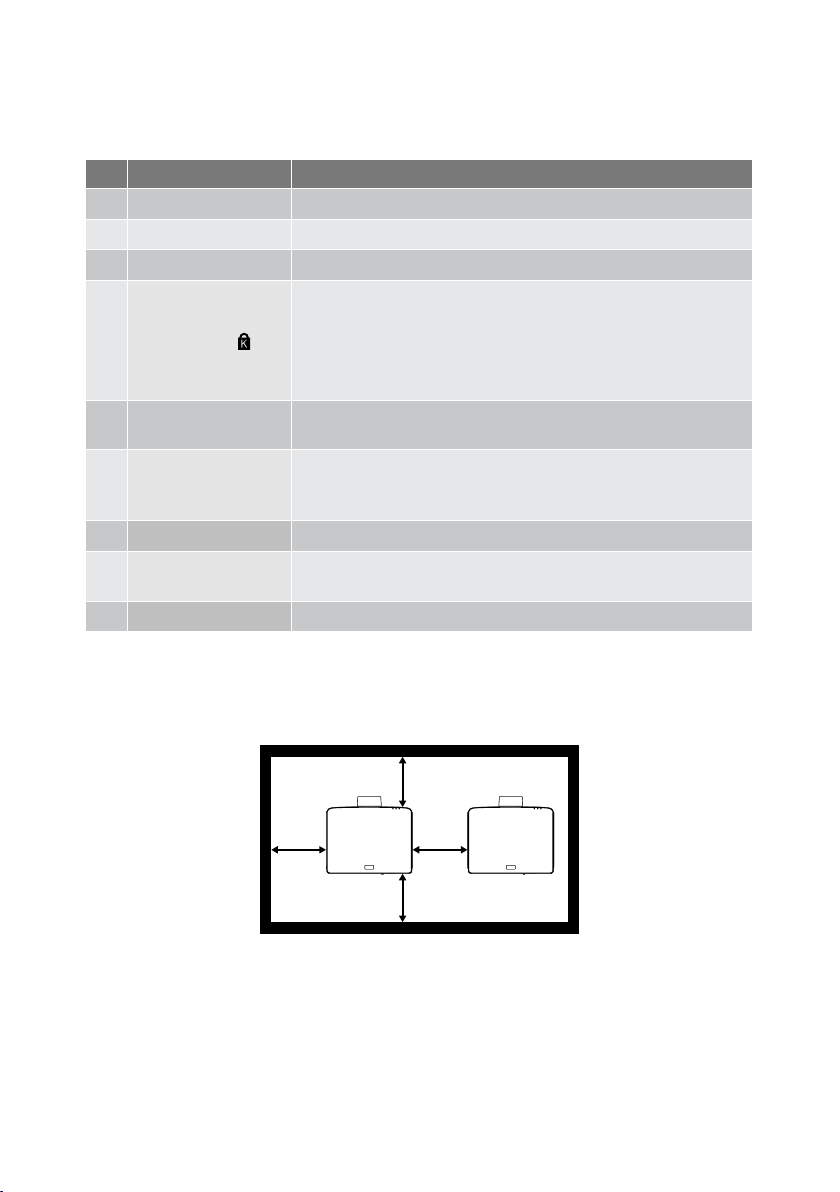
• Do not block projector intake and exhaust vents.
• When operating the projector in an enclosed space, allow at least 1m (39.4”) clearance
around the intake and exhaust vents.
)
• Security and theft protection lock compatible with
Kensington security cables/equipment. For products,
visit Kensington’s website.
Attach an anti-theft device. The security bar accepts
security wires or chains up to 0.18 inch/4.6 mm in diameter.
Use the buttons to power the projector on/o and
congure the projector settings. Refer to page 32 for
more details.
Connect the supplied power cord here, and plug the other
end into an active wall outlet.
≥1M
(≥39.4”)
≥1M
(≥39.4”)
≥1M
(≥39.4”)
(≥39.4”)
29
≥1M
Page 30
INTRODUCTION
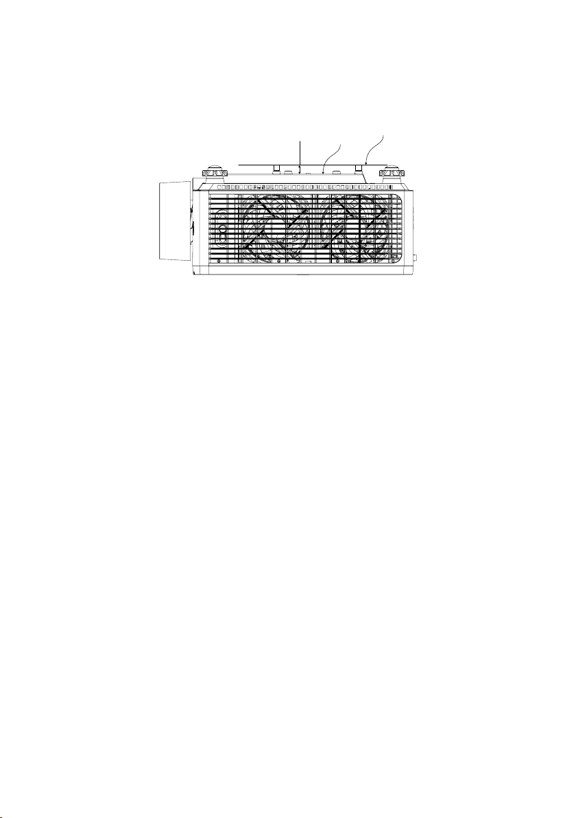
Ceiling Mount Plate
• Need to keep at least 15mm between the ceiling mount and bottom intake.
Bottom Intake
15mm
30
Page 31
INTRODUCTION
Connections
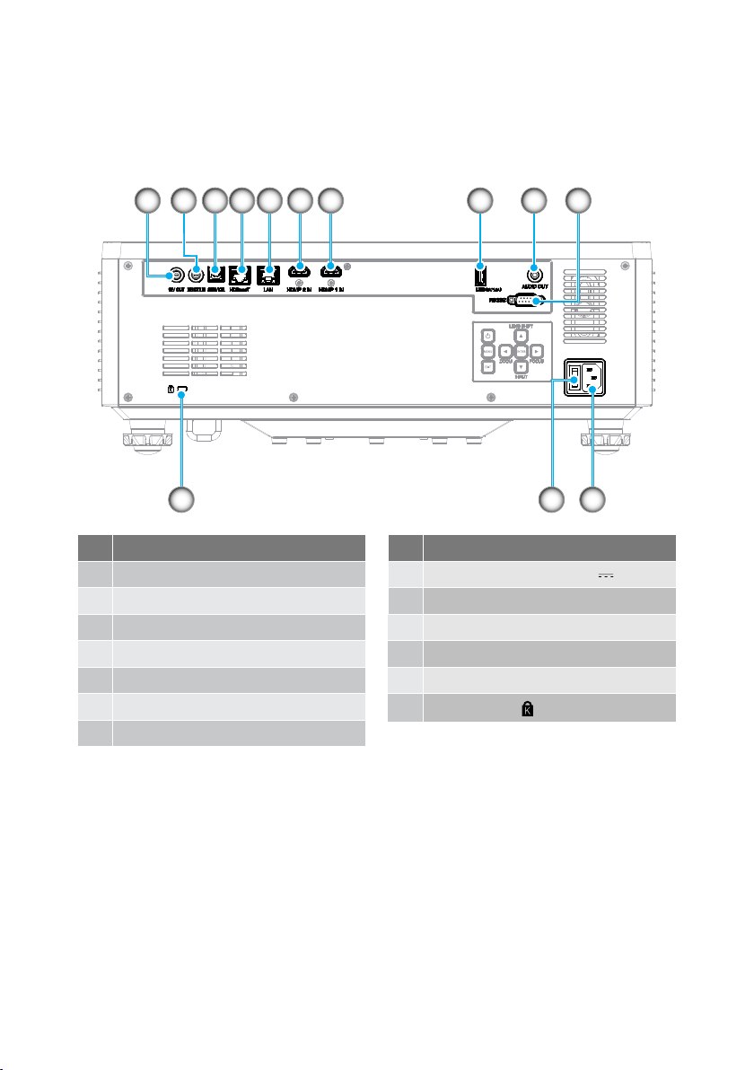
3 4 5 6 7 8 91 2
No. Item
1. 12V Out Connector
2. Remote In Connector (*1)
3. USB Connector
4. HDBaseT Connector
5. LAN Connector
6. HDMI 2 Connector
7. HDMI 1 Connector
10
12
No. Item
8. USB Connector (Power 5V
9. Audio Out Connector (*3)
10. RS-232 Connector
11. AC Inlet
12. Main Power Switch
13.
Security Slot (
)
1113
1.5A) (*2)
Note:
• *1 The system will automatically detect when a wired remote control is plugged in, and
when a wired remote control is detected, the system will disable the reception and
control of wireless remote control signals.
• *2 Not recommended for charging a cell phone.
• *3 Audio Out connector provides an audio signal output only if the projector is in the
power-on state.
31
Page 32
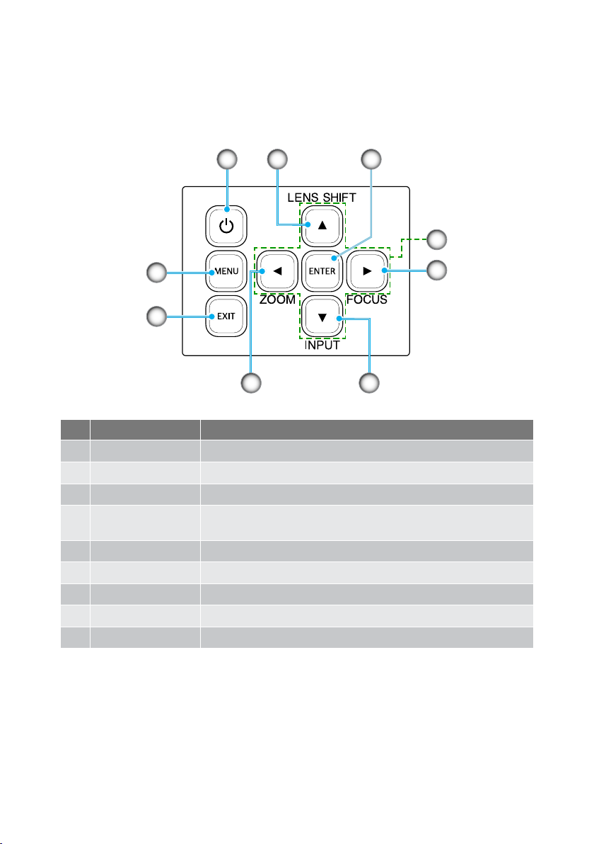
INTRODUCTION
Control Panel
1
9
8
32
4
5
67
No. Button Function
1. Power Button Turns the projector on or o.
2. Lens Shift Adjust the lens vertical / horizontal position.
3. Enter Conrm the settings.
Four Directional
4.
Select Keys
Navigation keys.
5. Focus Adjust the image focus.
6. Input Select the input signal port.
7. Zoom Adjust the image size.
8. Exit Returns to previous menu or exit menu if at top level.
9. Menu Shows the main menu on screen.
32
Page 33
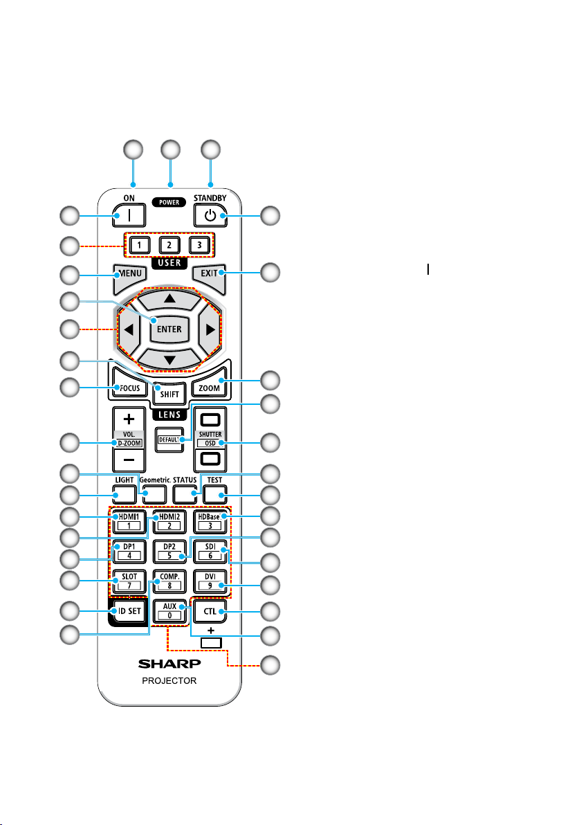
INTRODUCTION
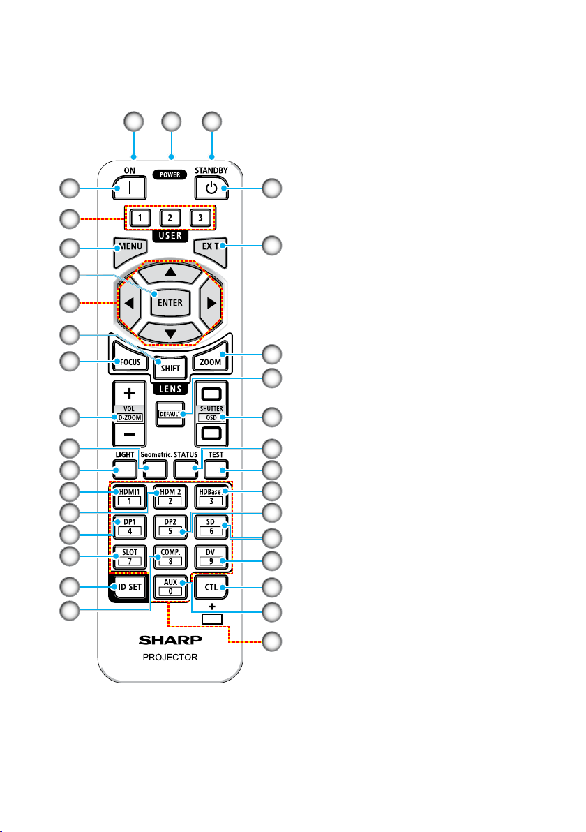
Remote Control
10
11
12
13
14
15
16
17
18
1 2 1
1. Infrared Transmitter
Remote control signals are sent via
infrared signal. Point the remote
control at the remote control receiver
on the projector.
3
4
5
6
19
2. Remote Jack
Connect a commercially available
remote cable here for wired operation.
3. POWER ON Button (
20
Turns power ON when in sleep or
standby mode.
)
4. USER 1/2/3 Button
7
The following 9 functions can be
selected and set. Available options
8
9
21
22
are Color Mode, A/V Mute, Color
Temperature, Orientation, Aspect
Ratio, Freeze Screen, Network Setup,
Audio Mute, and On Screen Display.
5. MENU Button
Displays the on-screen menu for
23
X
24
25
26
27
various settings and adjustments.
6. ENTER Button
Moves to the next menu when the
on-screen menu is displayed. Conrms
the item when the conrmation
message is displayed.
7.
pqtu Button
When the on-screen menu is
28
29
30
31
32
displayed, use the pqtu buttons
to select the item that you wish to set
or adjust.
8. SHIFT Button
The lens shift adjustment screen
will be displayed. Use the pqtu
buttons to adjust the lens position.
9. FOCUS Button
Opens the focus adjustment screen.
Adjust the focus (of the lens) with the
p/q buttons.
33
Page 34
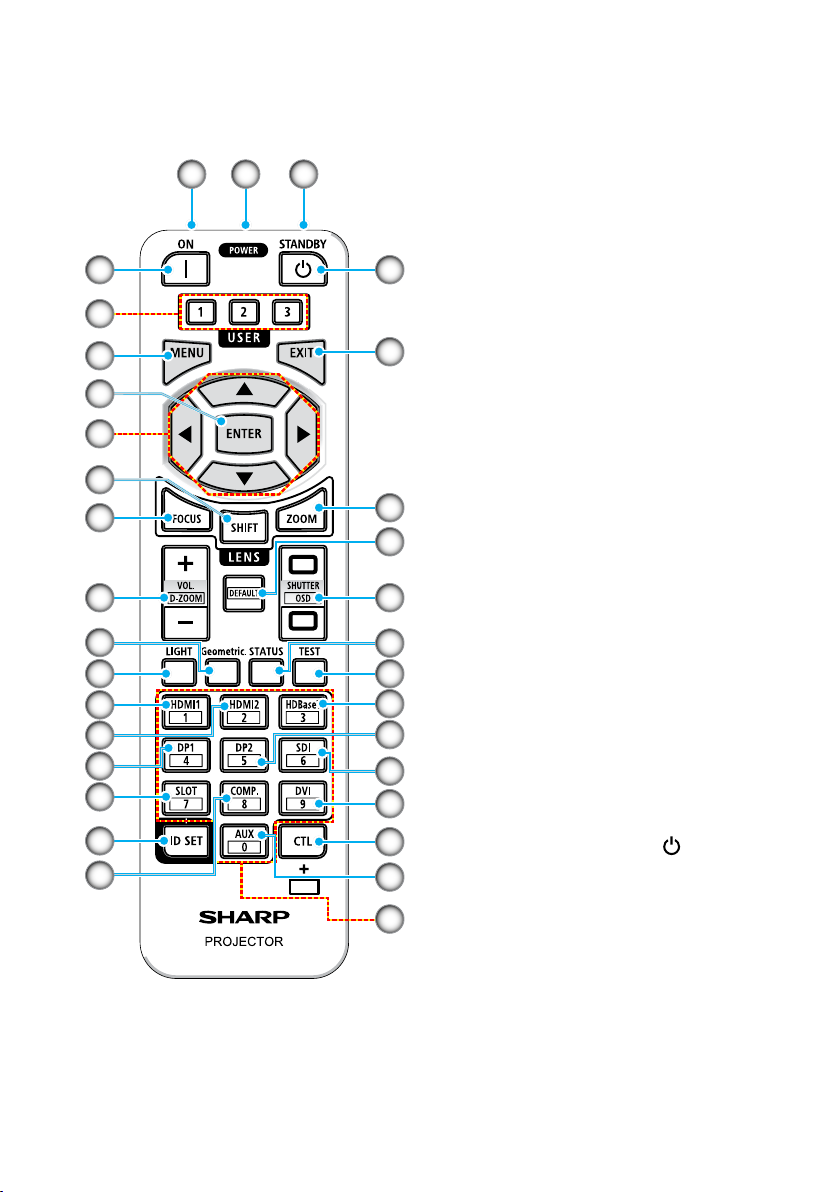
INTRODUCTION
10
11
12
13
14
15
16
17
18
1 2 1
10. VOL./D-ZOOM (+)(−) Button
Adjusts the volume level of the audio
output terminals. Simultaneously
pressing the CTL button will expand
or shrink the image (return to the
3
4
5
6
7
19
20
original state).
11. Geometric. Button
Displays [Geometric Correction] from
the on-screen menu. Use it to adjust
distortions in projected images.
12. LIGHT Button
Displays the light mode screen.
13. HDMI1 Button
Selects the HDMI1 input.
8
9
14. HDMI2 Button
21
22
Selects the HDMI2 input.
15. DP1 Button
(Not available on this series of
projectors.)
23
X
16. SLOT Button
(Not available on this series of
24
25
26
27
28
29
30
31
32
projectors.)
17. ID SET Button
Used to set the control ID when
performing individual operations on
multiple projectors using the remote
control.
18. COMP. Button
(Not available on this series of
projectors.)
19.
POWER STANDBY Button (
Pressing the button once will display
the shutdown conrmation message.
Press the POWER STANDBY button
once more to power down the
)
projector.
34
Page 35
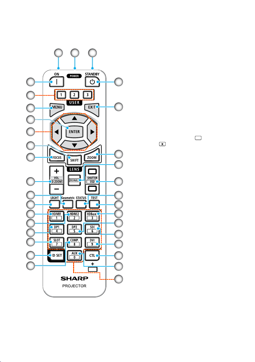
INTRODUCTION
10
11
12
13
14
15
16
17
18
1 2 1
20. EXIT Button
Returns to the menu on the previous
level when the on-screen menu is
displayed. Closes the menu when a
cursor appears in the main menu.
3
19
Cancels the operation when the
conrmation message is displayed.
4
5
6
7
8
9
21. ZOOM Button
20
Opens the zoom adjustment screen.
Adjust zoom with the p/q buttons.
22. DEFAULT Button
(Not available on this series of
projectors.)
23.
SHUTTER / OSD OPEN (
CLOSE (
21
22
Press the CLOSE button to turn o
the light source and temporarily stop
projection. Press the OPEN button
to resume. Simultaneously press the
) /
) Button
CTL and CLOSE buttons to close the
23
X
24
25
26
27
28
29
on-screen display (On-Screen Mute).
Simultaneously press the CTL and
OPEN buttons to go back.
24. STATUS Button
Displays [Information] from the
on-screen menu.
25. TEST Button
Projects a test pattern.
26. HDBaseT Button
Selects the HDBaseT input.
27. DP2 Button
30
(Not available on this series of
projectors.)
31
28. SDI Button
32
(Not available on this series of
projectors.)
35
Page 36
INTRODUCTION
10
11
12
13
14
15
16
1 2 1
29. DVI Button
(Not available on this series of
projectors.)
30. CTL Button
3
4
19
This is a multipurpose button for
combined use with other buttons.
31. AUX Button
(Not available on this series of
5
6
7
20
projectors.)
32. Numeric Keypad Button
Used to input the control ID when
performing individual operations on
multiple projectors using the remote
control (set the control ID). Pressing
8
9
X
21
22
23
24
25
26
27
28
29
the 0 button while holding down the
ID SET button will remove any control
ID settings.
17
18
30
31
32
36
Page 37
SETUP AND INSTALLATION
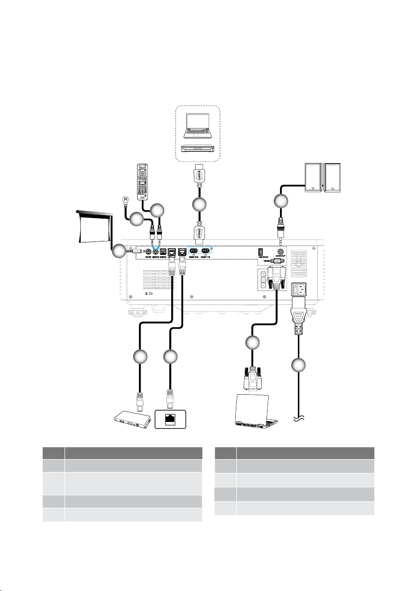
Connecting Sources to the Projector
X
2
2
1
78
No. Item
1. 12V DC Jack
2. Wired Remote Control Cable or
IR Receiver Cable (3.5mm TRS type)
3. HDMI Cable
4. Audio Out Cable
3
4
6
To wall outlet
No. Item
5. Power Cord
6. RS232C Cable (Cross Cable)
7. RJ-45 Cable (Cat.5e)
8. RJ-45 Cable (Cat.6A)
5
37
Page 38
SETUP AND INSTALLATION
Adjusting the Projector Image
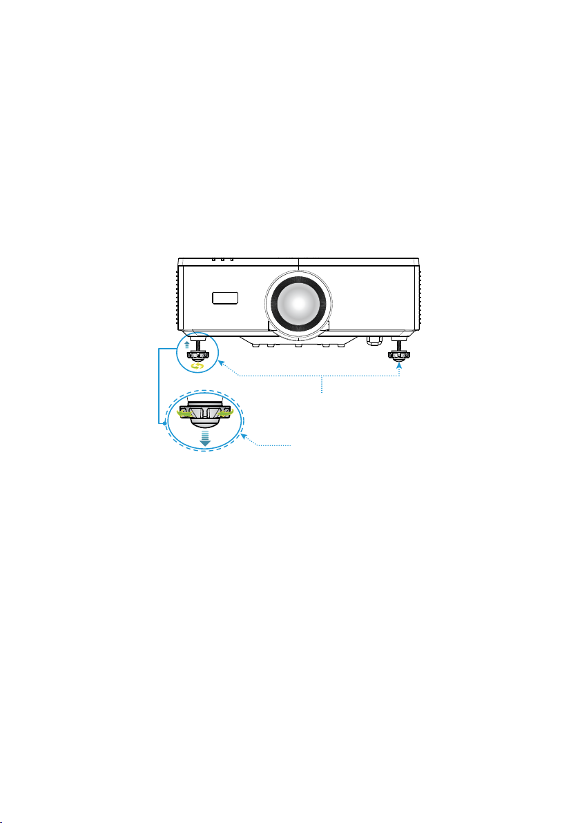
Adjusting the Projector’s Height
The projector is equipped with elevator feet for adjusting the image height.
1. Locate the adjustable foot you wish to adjust on the underside of the projector.
2. Rotate the adjustable foot clockwise or counterclockwise to raise or lower the
projector.
Tilt-Adjustment Feet
Tilt-Adjustment Ring
Note:
• Do not lengthen the tilt foot any more than 19 mm (0.75”). Doing so will make the
projector unstable.
• Do not use the tilt foot for any purpose other than adjusting inclination of the projector
installation angle. Handling the tilt foot improperly, such as carrying the projector by
grasping the tilt foot or hooking it onto a wall using the tilt foot, could damage the
projector.
38
Page 39
SETUP AND INSTALLATION
Lens Shift Range
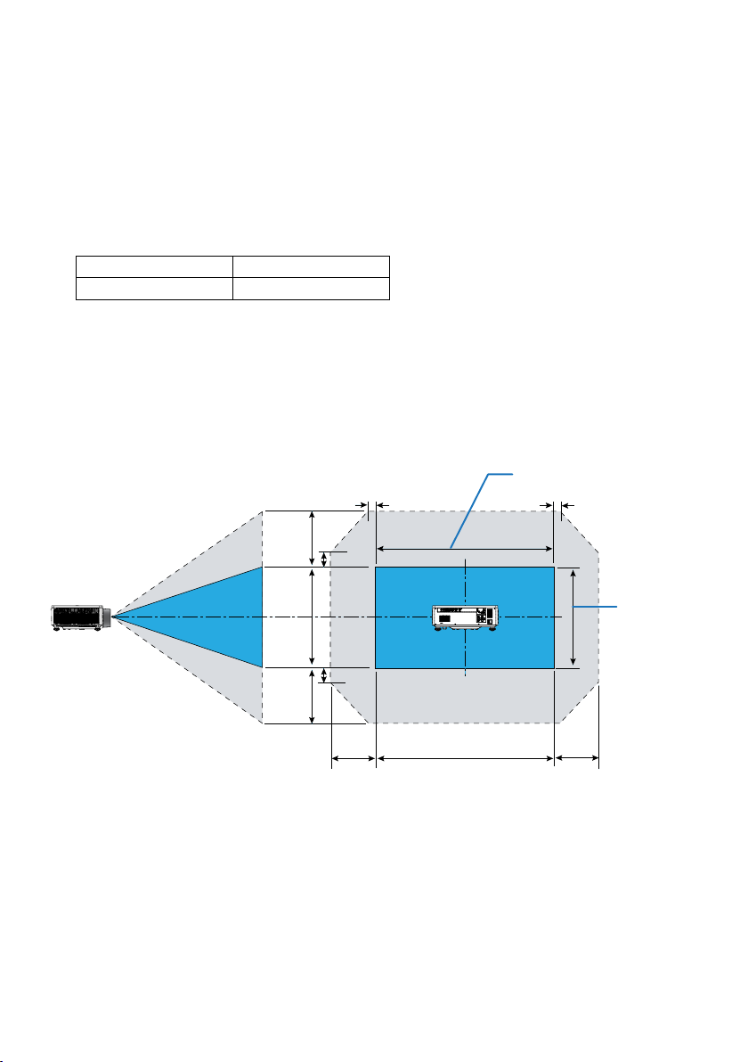
This device features a Motorized lens shift function that allows you to adjust the screen
position using the Remote control or Control Panel on the back of the projector (see page
32). You can perform lens shift within the following range.
Lens Shift Range
Vertical Direction Horizontal Direction
± 55% ± 25%
Note: If the lens shift exceeds the range shown in the diagram, the edges of the screen may
appear blurry or exhibit shadows.
The symbols represent:
• V for vertical (height of the projected screen).
• H for horizontal (width of the projected screen). The lens shift range is expressed as a
ratio of height and width.
Width of projected image
5%H
5%H
55%V
100%V
55%V
15%V
15%V
25%H
Height of
projected
image
25%H100%H
39
Page 40

SETUP AND INSTALLATION
Calculation Example: When projecting with 150 inches
• According to the “Image Size and Projection Distance” ( page 96), the screen
dimensions are H=332.1 cm and V=186.8 cm.
• Vertical Adjustment Range: You can move the projection screen upwards
by approximately 103 cm (0.55 x 186.8 cm
approximately 103 cm.
• Horizontal Adjustment Range: You can move the projection screen leftwards by
approximately 83 cm (0.25 x 332.1 cm
83 cm.
Note: There may be a few percent error due to the simplied calculation formula.
103 cm) and downwards by
83 cm) and rightwards by approximately
40
Page 41
SETUP AND INSTALLATION
Adjusting the Projector’s Zoom and Focus
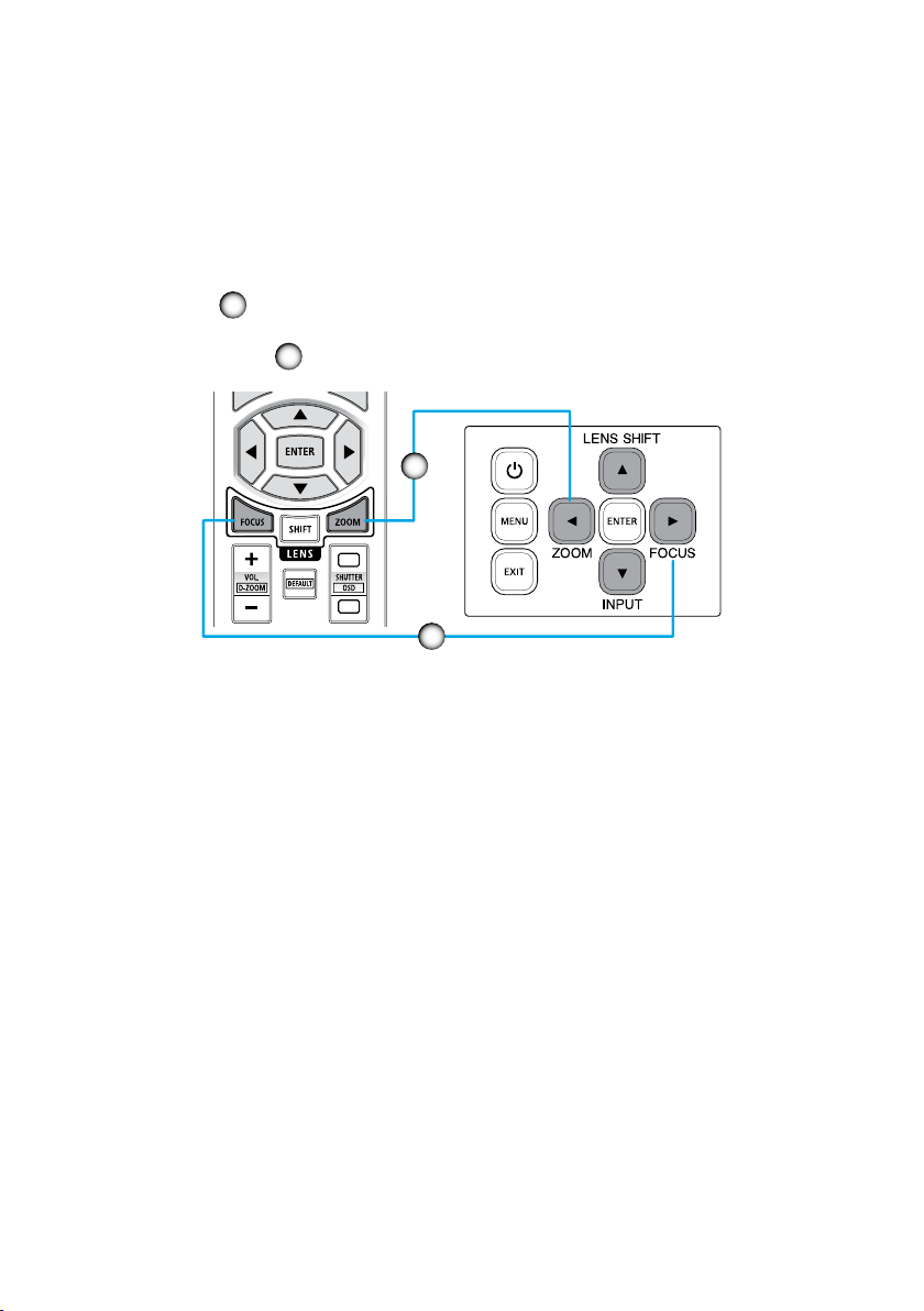
Use the remote control or projector keypad to adjust the zoom and focus of the projected
image.
• To adjust the image size, press ZOOM and the p/q buttons to get the required
image size.
• To adjust the image focus, press FOCUS and the p/q buttons until the image is
sharp and legible.
Note: Recommend to perform the focus adjustment after leaving the projector under the
A
B
A
X
B
state the Test Pattern has been projected for over 30 minutes. Please refer to page
53 and 69 about the Test Pattern.
41
Page 42
SETUP AND INSTALLATION
Adjusting the Projector Position
When you select a position for the projector, consider the size and shape of your screen,
the location of your power outlets, and the distance between the projector and the rest of
your equipment.
Follow these general guidelines:
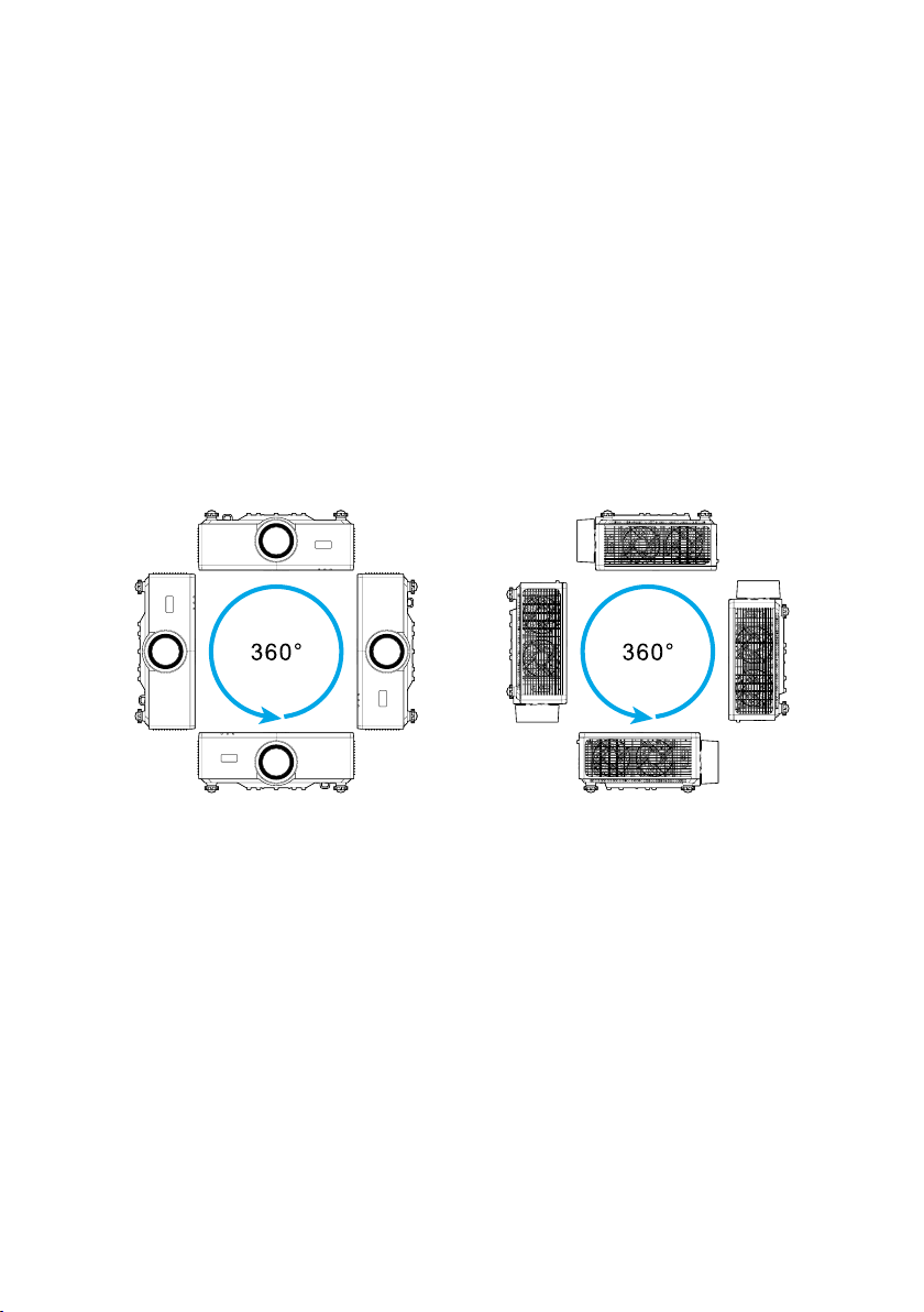
• Position the projector on a at surface at a right angle to the screen. The distance
must be at least 64.6 inch (1.64 m) from the projection screen.
• Position the projector to the desired distance from the screen. The distance from the
lens of the projector to the screen, the zoom setting, and the video format determine
the size of the projected image.
• Lens throw ratio: 1.25 ~ 2.0
• 360 degrees free orientation operation.
• When installing multiple projectors, keep at least 1m (39.4”) space between the
adjacent projectors.
• For ceiling/wall mount installations, make sure to leave 15 mm (0.6”) between the
ceiling mount and the bottom intake vents of the projector.
42
Page 43
SETUP AND INSTALLATION
Remote Setup
Battery Installation
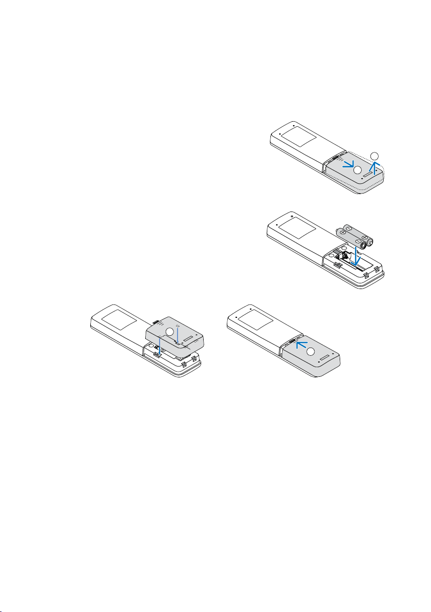
1. Press the catch and remove the battery cover.
2. Install new ones (AAA manganese or alkaline
batteries). Ensure that you have the batteries’
polarity (+/−) aligned correctly.
3. Slip the cover back over the batteries until it snaps into place.
1
2
1
2
Note: Do not mix dierent types of batteries or new and old batteries.
Remote Control Precautions
• Handle the remote control carefully.
• If the remote control gets wet, wipe it dry immediately.
• Avoid excessive heat and humidity.
• Do not short, heat, or take apart batteries.
• Do not throw batteries into re.
• If you will not be using the remote control for a long time, remove the batteries.
• Ensure that you have the batteries’ polarity (+/−) aligned correctly.
• Do not use new and old batteries together, or use dierent types of batteries
together.
• Dispose of used batteries according to your local regulations.
• Please note that if multiple projectors are installed nearby, other projectors may
unintentionally light up when you turn on the power using the remote control.
43
Page 44
SETUP AND INSTALLATION
Remote Control Eective Range
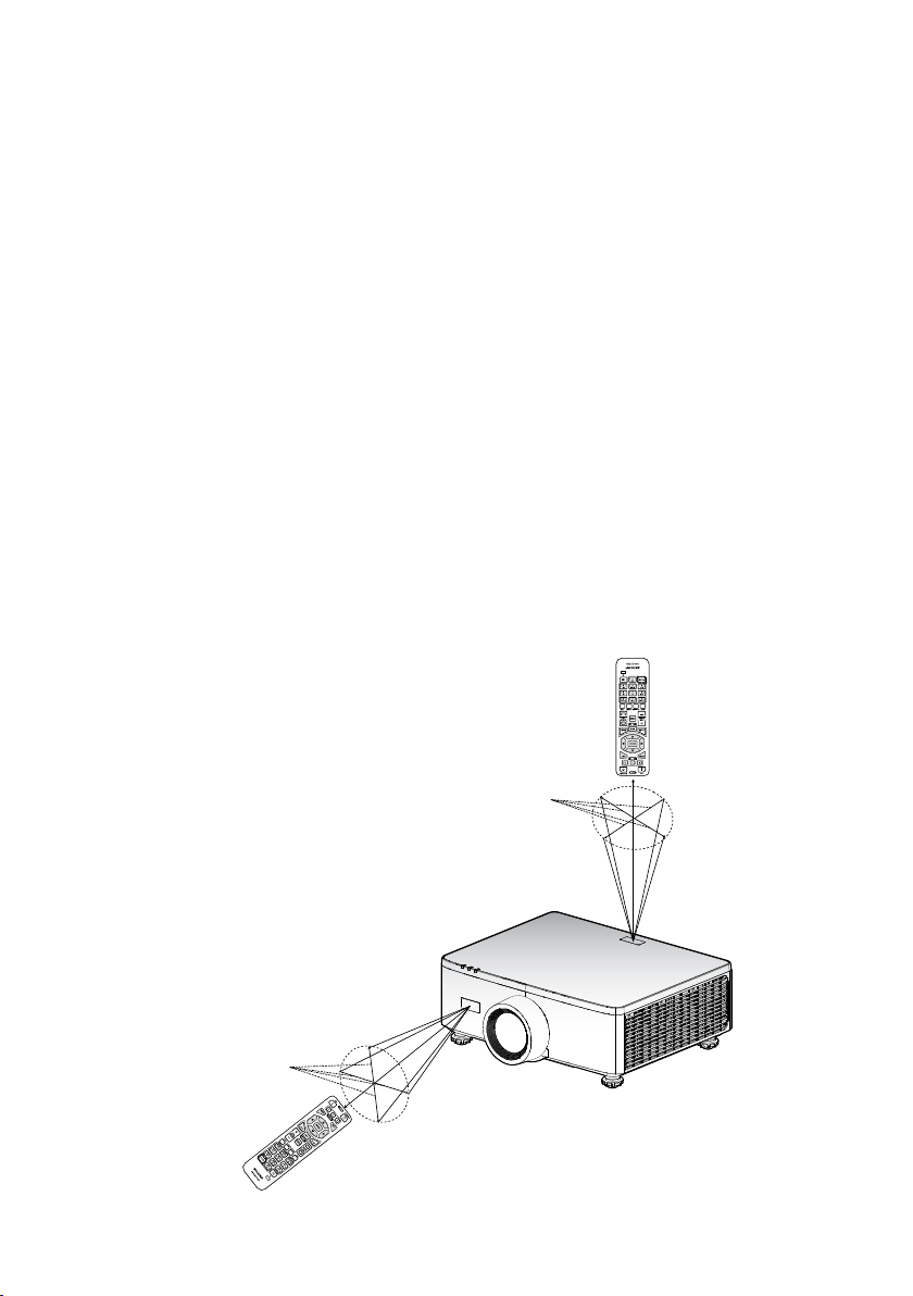
Infra-Red (IR) remote control sensor is located on the top and front of the projector.
Ensure to hold the remote control at an angle within 30 degrees perpendicular to the
projector’s IR remote control sensor to function correctly. The distance between the
remote control and the sensor should not be longer than 6 meters (19.7 feet) when
holding not longer than 8 meters (26.3 feet) when aiming the sensor at 0°.
• Make sure that there are no obstacles between the remote control and the IR sensor
on the projector that might obstruct the infra-red beam.
• Make sure the IR transmitter of the projector/remote control is not being shined by
sunlight or uorescent lamps directly.
• Please keep the remote controller away from uorescent lamps for over 2 m or the
remote controller might become malfunction.
• If the remote control is close to Inverter-Type uorescent lamps, it might become
ineective from time to time.
• If the remote control and the projector are within a very short distance, the remote
control might become ineective.
• When you aim at the screen, the eective distance is less than 5 m from the remote
control to the screen and reecting the IR beams back to the projector. However, the
eective range might change according to screens.
X
Approx. ±30°
Approx. ±30°
X
44
Page 45
USING THE PROJECTOR
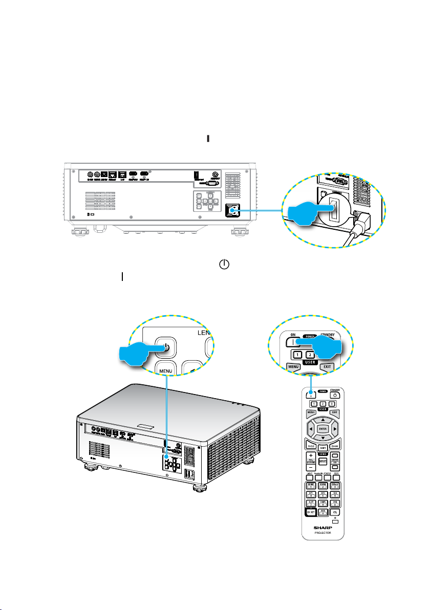
Powering On / O the Projector
Powering On
1. Securely connect the power cord and signal/source cable.
2. Set the main power switch to the “
becomes orange.
3. Turn on the projector by pressing the “ ” button on the projector keypad or the
POWER ON ( ) button on the remote control.
During startup the power LED is ashing red and during normal operation, the
power LED is solid green.
” (On) position and wait until the power LED
or
45
X
Page 46

USING THE PROJECTOR
Powering O
1. Turn o the projector by pressing the “ ” button on the projector keypad or the
POWER STANDBY ( ) button on the remote control. The following message will
be displayed:
Power O
Power O?
Press power key again.
2. Press the or POWER STANDBY ( ) button again to conrm, otherwise the
message will disappear after 15 seconds. When you press the
STANDBY ( ) button for the second time, the projector will shut down.
3. During the cooling cycle, the power LED is ashing green. When the power LED
turns solid orange, this indicates the projector has entered standby mode. If you
wish to turn the projector back on, you must wait until the cooling cycle has
nished and the projector has entered standby mode. When the projector is in
standby mode, simply press the “
button to turn on the projector.
4. Disconnect the power cord from the electrical outlet and the projector.
” button on the projector or the POWER ON ( )
or POWER
Note:
• It is not recommended that the projector is turned on immediately, right after a power o
procedure.
• By default, the projector turns o automatically after 20 minutes of inactivity. You can
modify the idle time length in “Auto Power o (min)” menu in “System Power Settings”.
If you want the projector to enter standby mode instead, disable auto power o and set
the sleep time interval in “System Power Settings O Timer (min)”.
46
Page 47
USING THE PROJECTOR
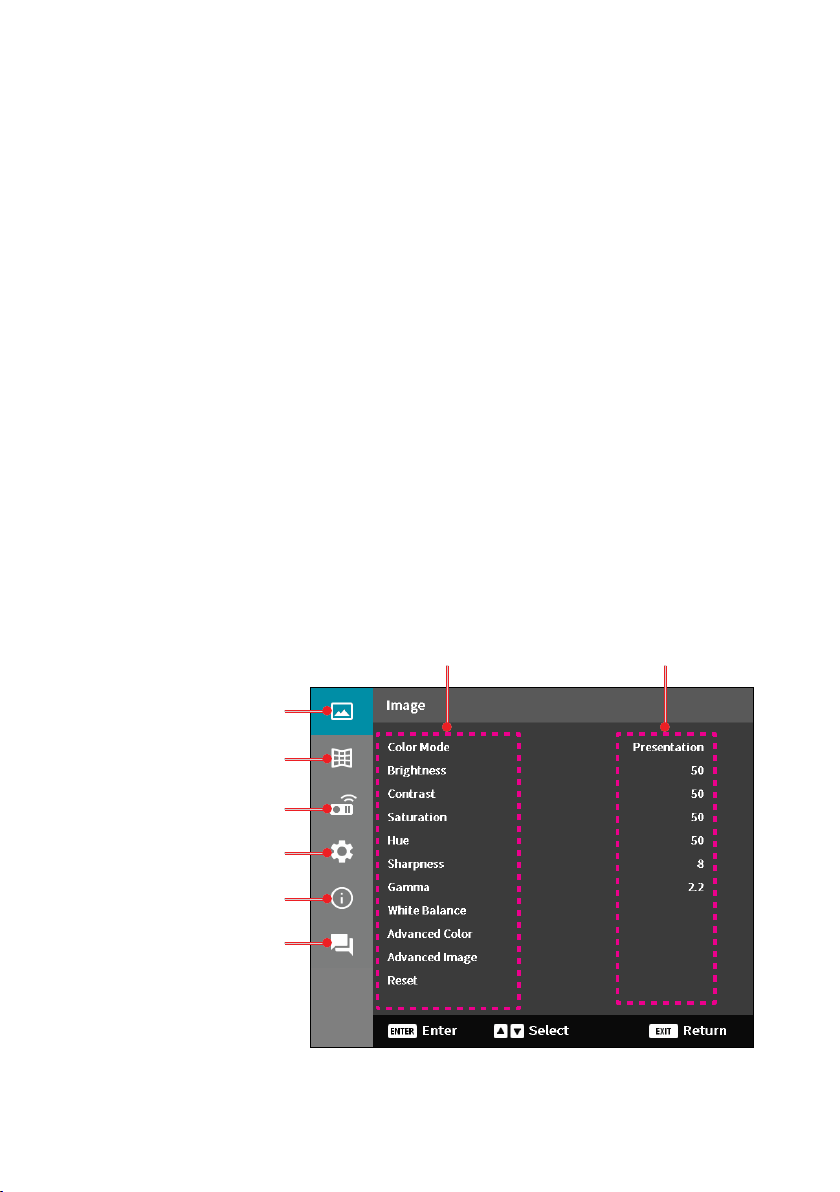
Menu Navigation and Features
The projector has multilingual on-screen display (OSD) menus that allow you to make
image adjustments and change a variety of settings.
1. To open the OSD menu, press the MENU key on the remote control or projector
keypad.
2. To select a main menu or sub menu, use the pq buttons to highlight it. Then,
press the ENTER button to enter the sub menu.
3. Press the EXIT button to return to the previous menu or exit the OSD menu if at
top level.
4. Setting methods to adjust the function value or selection an option.
• To adjust the slide bar values, highlight the function, and use the tu buttons
to change value.
• To check or uncheck a checkbox, highlight the function, and press ENTER.
• To input a number or symbol, highlight the number or symbol, and use the
p q buttons to make a selection. You can also use the number keys on the
remote control or keypad.
• To select a function option, use the pqtu buttons to make the selection.
If no ENTER icon shows at the navigation bar, the highlighted option is
automatically applied. If there is an ENTER icon at the navigation bar, press
ENTER to conrm your selection.
Submenus Settings
Image menu
Display menu
Communication menu
System menu
Information menu
Language menu
47
Page 48

USING THE PROJECTOR
OSD Menu Tree
Main Menu Sub Menu 2 Sub Menu 3 Sub Menu 4 Sub Menu 5 Option / Value Default
Image Color Mode Presentation Color mode
HDR
HLG
Cinema
sRGB
High Bright
DICOM SIM.
3D
High Frame Rate
Brightness 0 - 100 By Color Table
Contrast 0 - 100 By Color Table
Saturation 0 - 100 By Color Table
Hue 0 - 100 By Color Table
Sharpness 1 - 15 By Color Table
Gamma Graphics By Color Table
1.8
2.0
2.2
2.4
2.6
3D
Blackboard
DICOM SIM.
HDR
White
Balance
Color
Temperature
Red Gain 0 - 100 50
Green Gain 0 - 100 50
Blue Gain 0 - 100 50
Red Oset 0 - 100 50
Green Oset 0 - 100 50
Blue Oset 0 - 100 50
Warm By Color Table
Standard
Cool
defaults
depending on
source.
By Color Table
Color Mode
should reapplied
to previous user
setting after 3D
is turned on and
o.
Always autosave
image settings to
each mode.
48
Page 49

USING THE PROJECTOR
Main Menu Sub Menu 2 Sub Menu 3 Sub Menu 4 Sub Menu 5 Option / Value Default
Image Advanced
Color
Advanced
Image
Color Space Auto Auto
RGB(0~255)
RGB(16~235)
YUV
Wall Color O O
Blackboard
Light Yellow
Light Green
Light Blue
Pink
Gray
Color
Correction
Dynamic
Contrast
Dynamic
Range
3D Setup 3D Mode O Auto
Color Red Red
Green
Blue
Cyan
Magenta
Yellow
White
Hue 0 - 254 By Color Table
Saturation 0 - 254 By Color Table
Luminance 0 - 254 By Color Table
Reset Yes / No
Dynamic Black Checkbox Unchecked
Extreme Black Checkbox Unchecked
HDR O Auto
HDR
Brightness
3D Format Auto Auto
(Dialog box)
Auto
0 - 10 By HDR/HLG
source
Auto
Frame Packing
SBS
Top and Bottom
Frame
Sequential
49
Page 50

USING THE PROJECTOR
Main Menu Sub Menu 2 Sub Menu 3 Sub Menu 4 Sub Menu 5 Option / Value Default
Image Advanced
Image
Reset Yes / No
Display Lens Focus Focus In / Out
Aspect Ratio 4:3 Auto
Scale Digital Zoom 80 - 180 100
3D Setup 3D Sync Invert O O
On
Reset Yes / No
Zoom Zoom In / Out
Lens Shift Up (icon)
Lens Shift
Memory
Lens Shift
Calibration
Lens Lock O O
Reset Yes / No
Image Shift Horizontal 0 - 100 50
Save Memory Memory 1 -
Apply Memory Memory 1 -
Clear Memory Yes / No
Vertical 0 - 100 50
(Dialog box)
(Dialog box)
Down (icon)
Left (icon)
Right (icon)
Memory 5
Memory 5
(Dialog box)
Yes / No
(Dialog box)
On
(Dialog box)
16:9
21:9
Letter Box
Auto
No
No
50
Page 51

USING THE PROJECTOR
Main Menu Sub Menu 2 Sub Menu 3 Sub Menu 4 Sub Menu 5 Option / Value Default
Display Geometric
Correction
V Keystone 0 - 40 20
H Keystone 0 - 40 20
4-Corner Press “Up”/
”Down”/”Left”/
“Right” to
focus the point
and press
“OK” to select
the point.
Then press
“Up”/ ”Down”/
”Left”/ “Right”
to shift the
selected point
location.
[Default: TopLeft].
Top Left right (0 - 1152) 0
left (0 - 1152)
up (0 - 648) 0
down (0 - 648)
Top Right right (2688 -
Bottom Left right (0 - 1152) 0
Bottom
Right
3839)
left (2688 - 3839)
up (0 - 648) 0
down (0 - 648)
left (0 - 1152)
up (1512 - 2159) 2159
up (1512 - 2159)
right (2688 -
3839)
left (2688 - 3839)
up (1512 - 2159) 2159
up (1512 - 2159)
3839
3839
Warping O O
On
Warping
Adjustment
Grid Color Green Green
Reset Yes / No
51
(Execute)
Magenta
Red
Cyan
(Dialog box)
Page 52

USING THE PROJECTOR
Main Menu Sub Menu 2 Sub Menu 3 Sub Menu 4 Sub Menu 5 Option / Value Default
Display On Screen
Display
Background Blue Blue
Input Signal
Setting
Orientation Ceiling Auto Auto
Menu
Position
Menu Timer O 10s
Information
Hide
Auto Signal O On
Quick
Resync
Input Signal HDMI 1 HDMI 1
EDID
Settings
Reset Yes / No
Rear O O
HDMI 1 EDID 1.4 2.0
HDMI 2 EDID 1.4 2.0
HDBaseT EDID 1.4 2.0
Top Left Center
Top Right
Center
5s
10s
20s
30s
60s
O O
On
Black
On
O On
On
HDMI 2
HDBaseT
2.0
2.0
2.0
(Dialog box)
On
O
On
52
Page 53

USING THE PROJECTOR
Main Menu Sub Menu 2 Sub Menu 3 Sub Menu 4 Sub Menu 5 Option / Value Default
Display Test Pattern O O
Green Grid
Magenta Grid
White Grid
White
Black
Red
Green
Blue
Yellow
Magenta
Cyan
ANSI Contrast
4x4
Color Bars
Focus
Communication
Reset Yes / No
Remote
Setup
Remote
Code
Remote Lock O O
Remote
Sensor
User1 Color Mode A/V Mute
Front O On
Top O O
HDBaseT O O
(Dialog box)
0 - 99 0
1 - 9
On
On
On
A/V Mute
Color
Temperature
Orientation
Aspect Ratio
Freeze Screen
Network Setup
Audio Mute
On Screen
Display
53
Page 54

USING THE PROJECTOR
Main Menu Sub Menu 2 Sub Menu 3 Sub Menu 4 Sub Menu 5 Option / Value Default
Communication
Remote
Setup
Network
Setup
User2 Color Mode Freeze Screen
A/V Mute
Color
Temperature
Orientation
Aspect Ratio
Freeze Screen
Network Setup
Audio Mute
On Screen
Display
User3 Color Mode Audio Mute
A/V Mute
Color
Temperature
Orientation
Aspect Ratio
Freeze Screen
Network Setup
Audio Mute
On Screen
Display
LAN
Interface
Network
Status
MAC
Address
DHCP O O
IP Address - - - . - - - . - - - . - - - 192.168.0.100
Subnet Mask - - - . - - - . - - - . - - - 255.255.255.0
Gateway - - - . - - - . - - - . - - - 192.168.0.51
DNS 1 - - - . - - - . - - - . - - - 0.0.0.0
DNS 2 - - - . - - - . - - - . - - - 0.0.0.0
Apply Yes / No
Reset Yes / No
RJ-45 RJ-45
HDBaseT
Connected
Disconnected
AA:BB:CC:DD:FF:EE
On
(Dialog box)
(Dialog box)
54
Page 55

USING THE PROJECTOR
Main Menu Sub Menu 2 Sub Menu 3 Sub Menu 4 Sub Menu 5 Option / Value Default
Communication
System Standby
Control Crestron O On
On
PJ Link O On
On
AMX O On
On
HTTP O On
On
Baud Rate 9600 115200
19200
38400
57600
115200
Command
Format
Reset Yes / No
Mode
Power
Settings
Light Source
Setup
Keypad LED
Settings
Direct Power
On
Auto Power
On
Auto Power
O (min)
O Timer
(min)
Light Mode Normal Normal
Brightness
Level
A A
B
(Dialog box)
Normal Standby Normal Standby
Network
Standby
Sleep
O O
On
O O
On
0, 2-180 20
0-960 0
Eco.
Constant
Brightness
Light Power
Adjustment
10% - 100% 100%
O On
On
55
Page 56

USING THE PROJECTOR
Main Menu Sub Menu 2 Sub Menu 3 Sub Menu 4 Sub Menu 5 Option / Value Default
System Security Security O O
On
Security
Timer
Change
Password
12V Trigger O O
High
Altitude
Audio
Settings
User Data Save All
Reset Reset OSD Yes / No
Service
Information Projector Model Name
System
Status
Volume 0 - 10 5
Mute O O
Audio
Output
Reset Yes / No
Settings
Load All
Settings
Reset All Yes / No
Note: This menu is for service personnel only. Customers cannot use it.
Serial
Number
Standby
Mode
Total
Projector
Hours
Light Source
Hours
Ambient
Temp.
System
Temp.
Month 0 - 35 0
Day 0 - 29 0
Hour 0 - 23 0
On
O O
On
On
Auto Auto
Internal Speaker
Line Out
(Dialog box)
Memory 1 Memory 5
Memory 1 Memory 5
(Dialog box)
(Dialog box)
Memory 1
Memory 1
56
Page 57

USING THE PROJECTOR
Main Menu Sub Menu 2 Sub Menu 3 Sub Menu 4 Sub Menu 5 Option / Value Default
Information Control Remote
Communication
Signal Input Signal
FW Version Main Version
Code
Crestron
PJ Link
AMX
HTTP
LAN
Interface
MAC
Address
Network
Status
DHCP
IP Address
Subnet Mask
Gateway
DNS 1
DNS 2
Resolution
Signal
Format
Pixel Clock
Horz Refresh
Vert Refresh
Color Space
F-MCU
Version
A-MCU
Version
LAN Version
Formatter
Version
HDBaseT
Version
57
Page 58

USING THE PROJECTOR
Main Menu Sub Menu 2 Sub Menu 3 Sub Menu 4 Sub Menu 5 Option / Value Default
Language English English
German
French
Italian
Spanish
Swedish
Korean
Polish
Hungarian
Russian
Greek
Turkish
Portuguese
Arabic
Czech
T-Chinese
Norwegian
Dutch
Japanese
S-Chinese
Thai
58
Page 59

USING THE PROJECTOR
Image Menu
Learn how to congure image settings.
Submenus
• Color Mode
• Brightness
• Contrast
• Saturation
• Hue
• Sharpness
• Gamma
• White Balance
• Advanced Color
• Advanced Image
• Reset
Color Mode
There are several predened display modes that you can choose from to suit your
viewing preference. Each mode has been ne-tuned by our expert colour team to ensure
superior colour performance for wide range of content.
Presentation
In this mode, the color saturation and brightness are well-balanced.
HDR / HLG
Decodes and displays High Dynamic Range (HDR) / Hybrid Log Gamma (HLG)
content for the deepest blacks, brightest whites, and vivid cinematic color using
REC.2020 color gamut. This mode will be automatically enabled if HDR/HLG is set to
Auto (and HDR/HLG Content is sent to projector – 4K UHD Blu-ray, 1080p/4K UHD
HDR/HLG Games, 4K UHD Streaming Video). While HDR/HLG mode is active, other
display modes (Cinema, Reference, etc.) cannot be selected.
Cinema
Provides the best balance of detail and colors for watching movies.
sRGB
Standardized accurate color.
High Bright
This mode is suitable for environments where extra-high brightness is required,
such as using the projector in well-lit rooms.
59
Page 60

USING THE PROJECTOR
DICOM SIM.
This sets the settings to be similar to the DICOM standard used in the medical
industry.
Note: The [DICOM SIM.] option is for training/reference only and should not be used for
actual diagnosis.
3D
Optimized settings for watching 3D content.
Note: To experience the 3D eect, you will need to have compatible DLP Link 3D glasses.
See 3D section for more information.
High Frame Rate
High Frame Rate (HFR) refers to higher frame rates than typical prior practice.
Note: High Frame Rate mode only supports input with 1080p 120/240Hz timing and
cannot be manually set. The system automatically detects and switches to this mode.
Brightness
Adjust the luminous brightness of the projected image to adapt to dierent ambient
light.
Contrast
Adjust the contrast ratio of the projected image. The contrast controls the degree of
dierence between the lightest and darkest parts of the image.
Saturation
Adjust the saturation of the selected color. The value indicates the color shifts from or
towards the white in the center of the chromaticity diagram.
Hue
Adjust the color balance of red and green in video images.
Sharpness
Adjust the clarity of details in the projected image to make the image clearer and sharper.
60
Page 61

USING THE PROJECTOR
Gamma
Select an appropriate gamma value to optimize the image conformance to dierent input
sources.
Graphics
Best for projecting photos from PC input.
1.8 / 2.0 / 2.2 / 2.4 / 2.6
Select a preset gamma value to adjust the image performance. In general, the
smaller the value, the brighter the dark areas of the image will become. The
standard gamma value is 2.2.
3D
Best for playing 3D videos.
Blackboard
Best for projecting on to a blackboard.
DICOM SIM.
Best for projecting monochrome medical images, such as X-ray diagram.
HDR
Best for playing HDR videos.
White Balance
Adjust the white balance of the projected image via gain and oset. Gain and oset are
individual controls for each RGB channels used to set greyscale.
Color Temperature
Adjust the color temperature of the projected image. The available options are
Warm, Standard, or Cool.
Red / Green / Blue Gain
Adjust the color of the image’s bright areas.
Red / Green / Blue Oset
Adjust the color of the image’s dark areas.
Note:
• When 3D or High Frame Rate mode is selected, the Color Temperature will be
unavailable.
• When displaying a video with dierence color space (such as YCbCr), the Red Gain/Green
Gain/Blue Gain option will be unavailable.
61
Page 62

USING THE PROJECTOR
Advanced Color
Congure the color advanced settings of the projected image to improve the color
performance.
Color Space
Select a color space that has been specically tuned for the input signal. The
available options are Auto (default), RGB (0 ~ 255), RGB (16 ~ 235), and YUV.
Wall Color
Set the wall color of the projector to achieve best color performance for a specic
wall. The available options are O, Blackboard, Light Yellow, Light Green, Light Blue,
Pink, and Gray.
Color Correction
Change the color of a projected image by adjusting each color component in the
image. The adjustable color includes Red, Green, Blue, Cyan, Yellow, and Magenta
(R / G / B / C / Y / M).
• Red / Green / Blue / Cyan / Magenta / Yellow: Select a color for further
adjustment.
± Hue: Adjust the hue of the selected color. The value reects the number
of degrees of rotation around the chromaticity diagram from the
original color. Increasing value indicates counterclockwise rotation, and
decreasing value, clockwise rotation.
± Saturation: Adjust the saturation of the selected color. The value indicates
the color shifts from or towards the white in the center of the chromaticity
diagram.
± Luminance: Adjust the luminance of the selected color. Increase the value
to brighten the image (add white to a color) or decrease the value to
darken the image (add black to a color).
± Reset: Reset the Red, Green, Blue, Cyan, Magenta, or Yellow color to
factory default values.
• White: Adjust the white color performance via setting the Red, Green, and
Blue values.
± Red / Green / Blue: Adjust the red, green, and blue colors to optimize the
white color performance.
62
Page 63

USING THE PROJECTOR
Advanced Image
Congure other advanced settings of the projected image.
Dynamic Contrast
Set up the Dynamic Contrast to maximize the contrast for dark content.
• Dynamic Black: Enable this function to automatically adjust the contrast ratio
for video sources. It improves the black level in dark scenes by reducing the
light output.
• Extreme Black: Enable this function to automatically increase the contrast
ratio by turning o the laser light when black image is detected. This function
is only available for RGB signal format.
Note:
• When Dynamic Black is turned on, the Extreme Black will be unavailable.
• When Extreme Black is turned on, the Dynamic Black will be unavailable.
Dynamic Range
Congure the HDR (High Dynamic Range) setting and its eect when displaying
video from 4K Blu-ray players and streaming devices.
• HDR: Enable or disable the HDR function.
± O: Turn o HDR Processing. When set to O, the projector will NOT
decode HDR content.
± Auto: Auto detect HDR signal.
• HDR Brightness: Adjust the strength of HDR/HLG.
Note:
• For HDR signal, the default value is 5.
• For HLG signal, the default value is 3.
3D Setup
3D video le combines two slightly dierent images (frames) of the same scene
representing the dierent views that the left and right eyes see. When these frames
are displayed fast enough and viewed with 3D glasses synchronized with the left
and right frames, the viewer’s brain then assemble the separate images into a single
3D image. 3D Menu provides options to set up the 3D functions to correctly display
3D videos.
• 3D Mode: Enable or disable the 3D mode.
± O: Select “O” to turn o 3D mode.
± Auto: Select “Auto” to turn on 3D mode.
63
Page 64

USING THE PROJECTOR
• 3D Format: Use this option to select the appropriate 3D format content.
± Auto: When a 3D identication signal is detected, the 3D format is
selected automatically.
± Frame Packing: Display 3D signal in “Frame Packing” format.
± SBS (Side by Side): Display 3D signal in “Side-by-Side” format.
± Top and Bottom: Display 3D signal in “Top and Bottom” format.
± Frame Sequential: Display 3D signal in “Frame Sequential” format.
• 3D Sync Invert: Use this option to enable/disable the 3D sync invert function.
• Reset: Reset the function settings to factory default values
Note:
• This projector is a 3D ready projector with DLP-Link 3D solution.
• Please ensure that 3D glasses are in use for DLP-Link 3D content before enjoying
your video.
• This projector supports frame sequential (page-ip) 3D via HDMI1/HDMI2 ports.
• To enable 3D mode, the input frame rate should be set to 60Hz only, lower or
higher frame rate is not supported.
• To reach the best performance, resolution 1920x1080 is recommended, please note
that 4K (3840x2160) resolution is not supported in 3D mode.
• When 3D mode is selected, the Presentation, HDR, HLG, Cinema, sRGB, High Bright,
DICOM SIM., High Frame Rate, User mode will be unavailable.
Reset
Reset all the image settings to factory default values.
64
Page 65

USING THE PROJECTOR
Display Menu
Learn how to congure the settings to properly project images according to your
installation circumstances.
Submenus
• Lens
• Aspect Ratio
• Scale
• Geometric Correction
• On Screen Display
• Background
• Input Signal Setting
• Orientation
• Test Pattern
• Reset
Lens
Congure the lens settings to adjust the image quality and position.
Focus
Use the p and q buttons to adjust the focus of the projected image.
Zoom
Use the
Lens Shift
Use the p, q, t, u buttons to adjust the lens position to shift the projected area.
Lens Shift Memory
This projector can save up to ve lens settings, which records the lens position.
• Save Memory: Select a record from 1 to 5 to save the current lens settings.
• Apply Memory: Select a record from 1 to 5 to apply the lens settings.
• Clear Memory: Clear the saved lens records.
and buttons to adjust the size of the projected image.
Lens Shift Calibration
Calibrate the lens position to return it to the center.
Note:
• Ensure that the lens shift calibration has been executed before performing the lens
shift.
• Performing a lens shift calibration will clear the saved lens records.
• When the lens shift calibration is not completed, the lens shift memory will be
unavailable.
65
Page 66
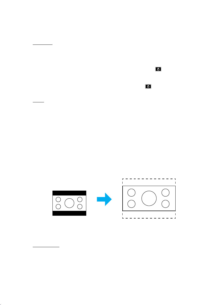
USING THE PROJECTOR
Lens Lock
Lock the lens to prevent the lens motors from moving, which disables all lens
functions.
Note:
• Enabling the Lens Lock function will display the lens lock icon [ ] at the upper
right corner of the screen.
• Focus, Zoom, Lens Shift, Lens Shift Calibration, and Lens Shift Memory will not
be available when the Lens Lock function is enabled. An [
upper right corner of the screen.
Reset
Reset the lens settings to factory default values.
Aspect Ratio
Set the aspect ratio of the projected image. The available options are 4:3, 16:9, 21:9, Letter
Box, or Auto. Select Auto to display the detected image size.
• 4:3: This format is for 4:3 input sources.
• 16:9: This format is for 16:9 input sources, like HDTV and DVD enhanced for Wide
screen TV.
• 21:9: This format is for 21:9 input source, like HDTV and DVD enhanced for Wide
screen TV.
• Letter Box: To ensure that the letterbox signal is properly projected, it will be
enlarged equally in both the vertical and horizontal directions.
] icon appears at the
Letter box
• Auto: Automatically selects the appropriate display format.
Scale
Digital Zoom
Use to reduce or magnify an image on the projection screen. Digital Zoom is not the
same as optical zoom and can result in degradation of image quality.
Note: Zoom settings are retained on power cycle of the projector.
66
Page 67
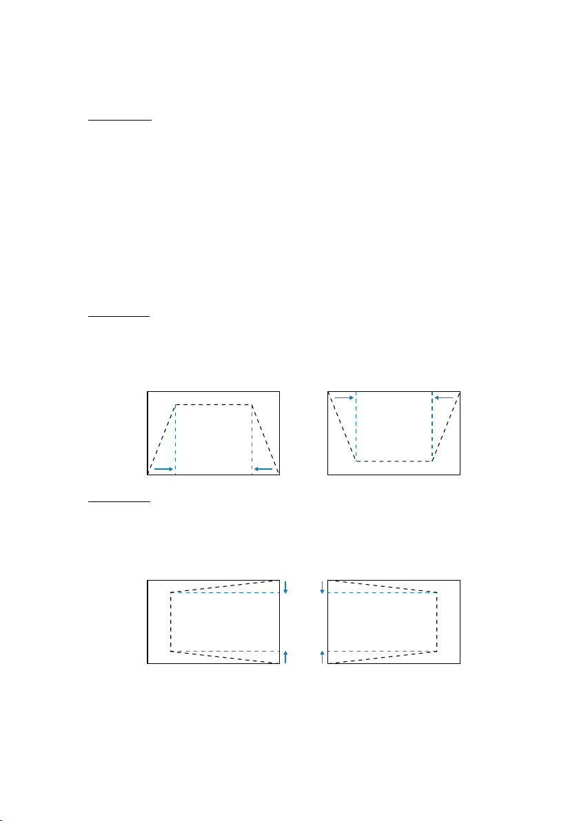
USING THE PROJECTOR
Image Shift
Adjust the projected image position.
• Horizontal: Use the t and u buttons to adjust the projected image position
horizontally.
• Vertical: Use the p and q buttons to adjust the projected image position
vertically.
Note: When the input signal is 2K resolution timing and 3D timing, image shifting will
not be available.
Geometric Correction
Congure the geometric settings to reshape the image for dierent projection surfaces.
V Keystone
Adjust image distortion vertically and make a squarer image. Vertical keystone
is used to correct a keystoned image shape in which the top and bottom are
slanted to one of the sides. This is intended when for use with vertically on-axis
applications.
H Keystone
Adjust image distortion horizontally and make a squarer image. Horizontal
keystone is used to correct a keystoned image shape in which the left and right
borders of the image are unequal in length. This is intended for use with vertically
on-axis applications.
67
Page 68
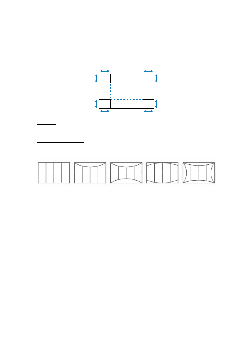
USING THE PROJECTOR
4-Corner
Reshape the image by moving the 4 corners of the image to have it t a specic
projection surface.
Warping
Enable or disable the application of warping adjustment eect.
Warping Adjustment
Use warping to adjust the image to align with the border of the projection surface
(screen) or to eliminate image distortion (cause by an uneven surface).
Grid Color
Select a grid color for warp between Green, Magenta, Red, and Cyan.
Reset
Reset geometric correction settings to factory default values.
On Screen Display
Menu Position
Select the menu location from Top Left, Top Right, and Center.
Menu Timer
Set the length of time the menu displays on the screen.
Information Hide
Enable or disable the corner information messages, such as input source, IP address,
and so on.
68
Page 69

USING THE PROJECTOR
Background
Set a background color to display when no input signal is detected. The available options
are Blue and Black.
Input Signal Setting
Learn how to congure the projector input settings.
Auto Signal
When Auto Signal is enabled, the projector automatically detects and selects
the input signal. Once an input source is selected, press the Input button on the
remote control or keypad to switch to other available sources. When the function is
disabled, pressing Input will bring up the Active Inputs submenu.
Quick Resync
When this function is enabled, auto signal detection will be faster.
Input Signal
Select an input signal from the source list. The available input sources are HDMI1,
HDMI2, and HDBaseT.
EDID Settings
Switch EDID versions.
• 1.4: Compatible with standard video signals.
• 2.0: Supports 4K video signals. Set this when displaying 4K video using a
device that supports 4K video.
Reset
Reset the signal settings to factory default values.
Orientation
Change the image direction by selecting a proper projection mode.
Ceiling
Enable the function for ceiling mount installation.
Rear
Check the function for rear projection.
Test Pattern
Select a test pattern. The available options are O, Green Grid, Magenta Grid, White Grid,
White, Black, Red, Green, Blue, Yellow, Magenta, Cyan, ANSI Contrast 4x4, Color Bars, and
Focus.
69
Page 70

USING THE PROJECTOR
Reset
Reset all the display settings to factory default values.
70
Page 71

USING THE PROJECTOR
Communication Menu
Communication menu is used to congure the settings that allow the projector to
communicate with other projectors or control devices.
Submenus
• Remote Setup
• Network Setup
• Control
• Baud Rate
• Command Format
• Reset
Remote Setup
Congure the settings of the Infra-Red (IR) remote control.
Remote Code
Setting the Remote Code can prevent interference from other identical remote controls.
After adjusting this setting, you must also change the corresponding control ID on the
remote control. Please refer to the ID SET button function description in item 17 on
page 34.
Remote Lock
The IR receiving function of the projector can be temporarily deactivated by hot key
(0 ~ 9) to avoid the IR interference between projectors. The remote ID needs to be
set to All.
Note: Enabling the Remote Lock function will display the remote lock icon [ ] at the
upper right corner of the screen.
Remote Sensor
Set the remote receiver for the projector to control the communication between
the projector and the IR remote.
• Front: Enable or disable the front remote receiver.
• Top: Enable or disable the top remote receiver.
• HDBaseT: Select On to set the HDBaseT terminal as the remote receiver.
Note:
• Only one of the Front and Top IR receivers can be turned on or o at the same time.
• The system will automatically detect when a wired remote control is plugged in,
and when a wired remote control is detected, the system will disable the reception
and control of wireless remote control signals.
71
Page 72

USING THE PROJECTOR
User 1 / User 2 / User 3
Assign a function to the User 1, User 2, and User 3 buttons on the remote control.
It allows you to use the function easily without going through the OSD menus.
The available functions are Color Mode, A/V Mute, Color Temperature, Orientation,
Aspect Ratio, Freeze Screen, Network Setup, Audio Mute, and On Screen Display.
Note: When the Freeze and Audio Mute functions are enabled, the respective icon will
appear at the upper right corner of the screen:
Freeze icon [ ] / Audio Mute icon [ ].
Network Setup
Congure the projector’s network settings.
LAN Interface
Specify the LAN interface to RJ-45 or HDBaseT.
Network Status
Display the network connection status. (Read only)
MAC Address
Display the MAC address. (Read only)
DHCP
Turn on DHCP to automatically acquire IP address, subnet mask, gateway, and DNS.
IP Address
Assign the projector’s IP address.
Subnet Mask
Assign the projector’s subnet mask.
Gateway
Assign the projector’s gateway.
DNS 1/DNS 2
Assign the projector’s DNS 1/DNS 2.
Apply
Apply the wired network settings.
Note: If you have adjusted the settings of DHCP, IP Address, Subnet Mask, Gateway,
DNS1/2, please be sure to execute “Apply” before the system will apply the
settings to the network settings.
Reset
Reset the network settings to default factory values.
72
Page 73

USING THE PROJECTOR
Control
This projector can be controlled remotely by a computer or other external devices
through wired network connection. It allows the user to control one or more projectors
from a remote control center, such as powering the projector on or o, and adjusting the
image brightness or contrast.
Use the Control submenu to select a control device for the projector.
Crestron
Control the projector with Crestron controller and related software (Port: 41794).
For more information, please visit https://www.crestron.com.
PJLink
Control the projector with PJLink Class2 commands (Port: 4352).
For more information, please visit http://pjlink.jbmia.or.jp/english.
AMX
Control the projector with AMX devices (Port: 9131).
For more information, please visit http://www.amx.com.
HTTP
Control the projector with web browser (Port: 80).
For more information, refer to “Overview of the web control panel” on page 76.
Baud Rate
Set the baud rate for Serial Port In and Serial Port Out. The available options are 9600,
19200, 38400, 57600, and 115200 (default).
Command Format
Switch between the available control commands. For the two supported control
functions and commands, refer to the ‘RS232 Protocol Function List’ table on page 105.
Reset
Reset all control settings to default factory values.
73
Page 74
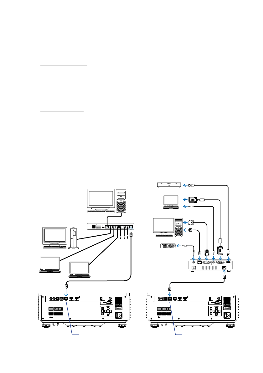
USING THE PROJECTOR
Setup Network Control
LAN / RJ45 function
For simplicity and ease of operation, the projector provides diverse networking and
remote management features.
The LAN / RJ45 function of the projector through a network, such as remotely
manage: Power On / O, brightness, and contrast settings.
HDBaseT function
Use a LAN cable sold commercially to connect the HDBaseT port of the projector to
a HDBaseT transmission device sold commercially.
The HDBaseT port of the projector supports HDMI signals (HDCP) from transmission
devices, control signals from external devices (serial, LAN) and remote control
signals (IR commands).
Note: Refer to the owner’s manual accompanied with your HDBaseT transmission for
connecting with your external devices.
Connection examples of the wired LAN and HDBaseT
HDMI output video device
Server
Computer (for output use)
Hub
Computer (for control use)
Remote control
REMOTE
RS-232C
LAN
Example of a transmission device
LAN port HDBaseT port
74
AUDIO IN HDMI IN
COMPUTER IN
HDBaseT
Page 75

USING THE PROJECTOR
Wired LAN terminal functionalities
This projector can be controlled via the LAN port using a PC (laptop) or other
external devices, supporting control functions such as NaViSet Administrator 2 /
Web control / Crestron Connected V2 / AMX (Device-Discovery) / PJLink Class2.
Using the web control panel
The web control panel allows the user to congure various projector settings using
a web browser from any personal computer or mobile devices.
System Requirements
To use the web control panel, make sure your devices and software meet the
minimum system requirements
• RJ45 cable for HDBaseT port: CAT.6A
• RJ45 cable for LAN port: CAT.5e
• PC, laptop, mobile phone, or tablet installed with a web browser
75
Page 76
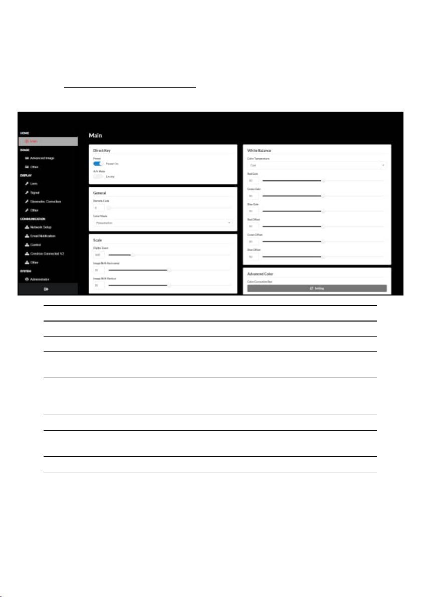
USING THE PROJECTOR
Overview of the web control panel
Congure the projector settings using web browser.
Menu Description
HOME View the projector information and rmware version details.
IMAGE To congure image settings.
DISPLAY To congure the settings to properly project images according to
your installation circumstances.
COMMUNICATION Communication menu is used to congure the settings that allow
the projector to communicate with other projectors or control
devices.
SYSTEM To congure the system settings for the projector.
INFORMATION View the projector information about its status and settings. The
projector information is read only.
LANGUAGE Set system display language.
76
Page 77

USING THE PROJECTOR
Accessing the web control panel
When network is available, connect the projector and the computer to the same
network. Use the projector address as the web URL to open the web control panel in
a browser.
1. Check the projector address using the OSD menu.
• Setup: Communication Network Setup IP Address.
2. Open a web browser and type the projector address in the address bar.
3. The web page redirects to the web control panel.
4. On rst access, in the Username and Password elds, enter your username and
password as follows:
• Username: admin
• Password: (Keep blank and no need to enter)
Note:
• When logging in for the rst time, you don’t need to enter a password.
• It is needed to enter the own password once you have logged in. It is also advised
to use a strong password.
• When you enter the password, pay enough attention to people around for the
password abuse protection. If you have anxiety the password is cheated, change
the password immediately.
77
Page 78
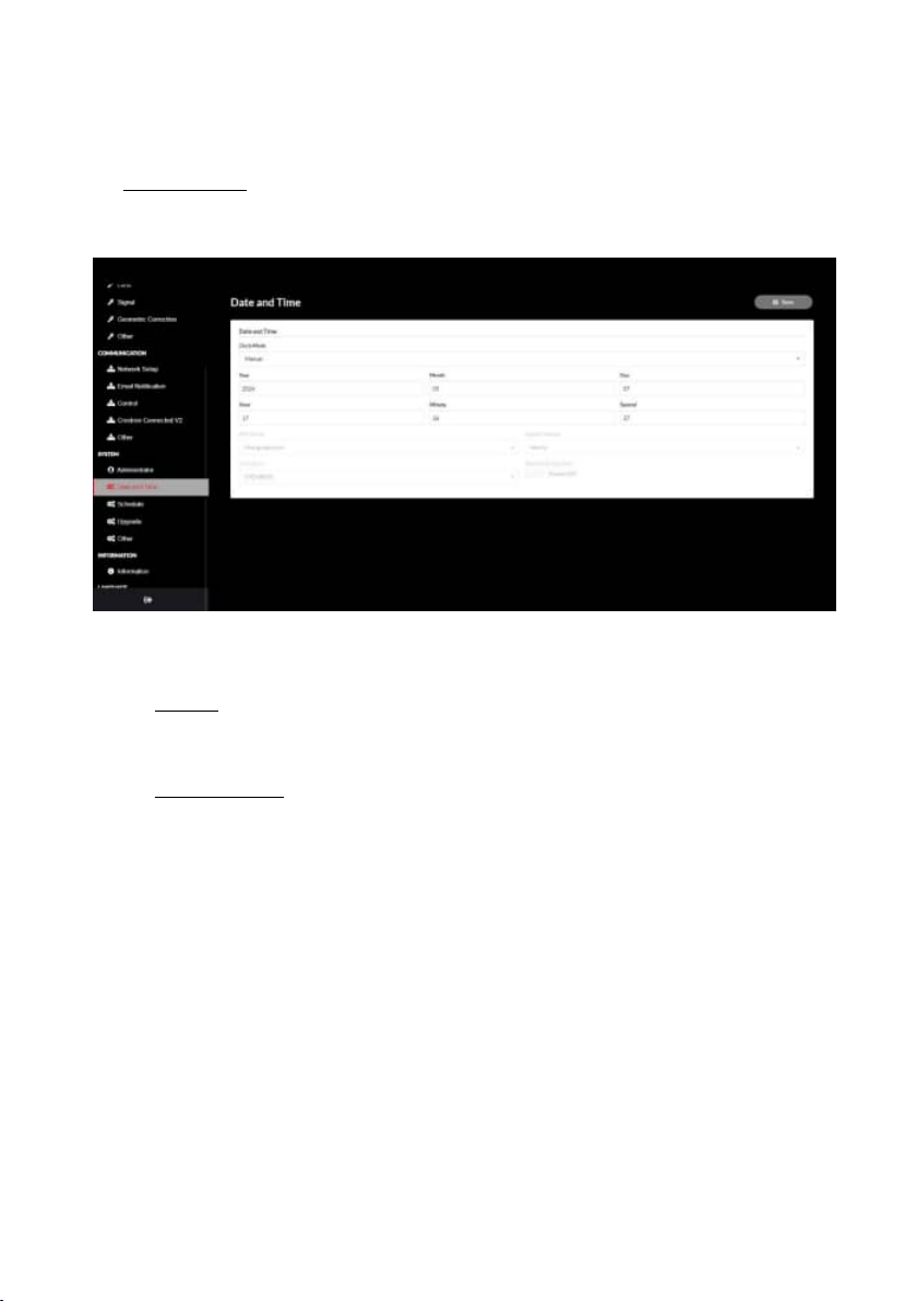
USING THE PROJECTOR
Date and Time
The projector can set the system date and time, and can automatically adjust the time
through the NTP server.
Clock Mode
You can choose to adjust the time manually or through the NTP server.
Manual
Manually set the system date and time. If “Manual” setting is enabled, only Year/
Month/Day/Hour/Minute/Second settings can be adjusted.
Use NTP Server
Correct the system date and time in the corresponding time zone through NTP
Server. If “Use NTP Server” setting is enabled, only NTP Server/Update Interval/
Time Zone/Daylight Saving Time settings can be adjusted.
Year
Manually adjust year settings. The adjustment range is 2000 - 2037.
Month
Manually adjust month settings. The adjustment range is 1 - 12.
Day
Manually adjust day settings. The adjustment range is 1 - 31.
Hour
Manually adjust hour settings. The adjustment range is 00 - 23.
Minute
Manually adjust minute settings. The adjustment range is 00 - 59.
78
Page 79

USING THE PROJECTOR
Second
Manually adjust second settings. The adjustment range is 00~59.
NTP Server
The system provides the following commonly used NTP servers to choose from:
1. time.google.com
2. asia.pool.ntp.org
3. europe.pool.ntp.org
4. north-america.pool.ntp.org
Update Interval
The interval at which the system automatically synchronizes time to the NTP server.
Supports Hourly/Daily.
Time Zone
The system supports 38 time zone options from UTC+14 to UTC-12.
Daylight Saving Time
The daylight saving time setting can be enabled or disabled according to the needs
of the area of use. When DST is enabled, the system will automatically adjust the time
according to the selected time zone.
79
Page 80
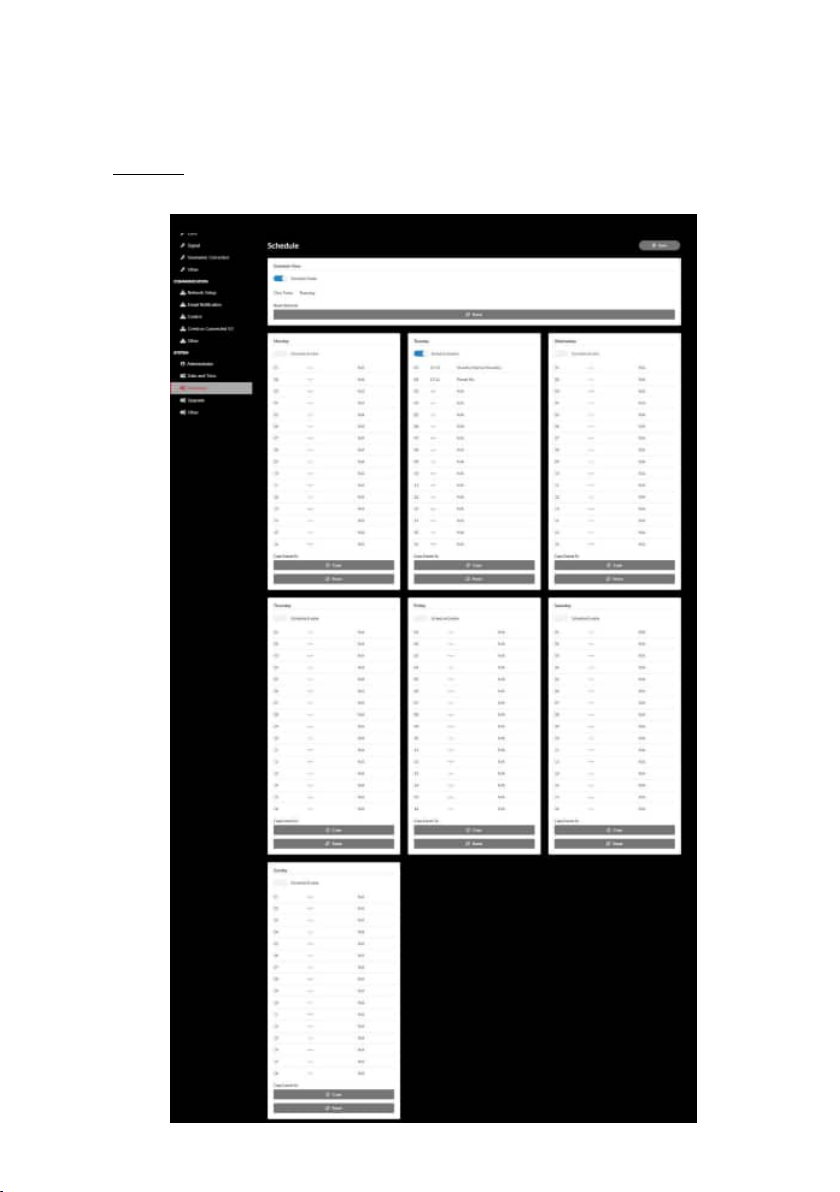
USING THE PROJECTOR
Schedule
The projector can be scheduled to perform repeated functions every day of the week.
80
Page 81

USING THE PROJECTOR
Schedule View
Display the current input signal of the projector.
Schedule Mode
Enable/Disable all scheduled events.
View Today
Display the current day of week.
Reset Schedule
Reset all scheduled events settings.
Monday – Sunday
Display list of scheduled events for day of week.
Schedule Enable
Enable/disable all scheduled events for the day.
Event 01 - 16
Supports up to 16 events per day.
Create Schedule
Create new event for day.
Hour
User can set 00 to 23 for hour.
Minute
User can set 00 to 59 for minute.
Function
Supports Power Settings / Input Source / Light Mode / A/V Mute of
functions.
Event
Provides the following events based on user selection function:
1. Power Settings
i. Power On: Trigger projector power on.
ii. Standby (Normal Standby): Trigger the projector into standby and
set the power setting to Normal Standby.
iii. Standby (Network Standby): Trigger the projector into standby and
set the power setting to Network Standby.
iv. Standby (Sleep): Trigger the projector into standby and set the
power setting to Sleep.
81
Page 82

USING THE PROJECTOR
2. Input Source
i. HDMI 1: Trigger the projector to switch input source to HDMI 1 port.
ii. HDMI 2: Trigger the projector to switch input source to HDMI 2 port.
iii. HDBaseT: Trigger the projector to switch input source to HDBaseT
port.
3. Light Mode
i. Normal: Trigger the projector and set the light mode to Normal.
ii. Eco.: Trigger the projector and set the light mode to Eco..
iii. Constant Brightness: Trigger the projector and set the light mode to
Constant Brightness.
iv. Light Power Adjustment: Trigger the projector and set the light
mode to Light Power Adjustment.
4. A/V Mute
i. A/V Mute On: Trigger the projector to mute Video and Audio.
ii. A/V Mute O: Trigger the projector to disabled mute Video and
Audio.
Copy Events To
Copy events scheduled throughout the day.
Current Day
Show today’s week.
Copy To
Users can copy today’s scheduled events to other days (Sunday to Saturday).
Reset
Reset scheduled events for the day.
82
Page 83

USING THE PROJECTOR
System Menu
Learn how to congure the system settings for the projector.
Submenus
• Standby Mode
• Power Settings
• Light Source Setup
• Keypad LED Settings
• Security
• 12V Trigger
• High Altitude
• Audio Settings
• User Data
• Reset
Standby Mode
Setup the projector’s standby mode.
Normal Standby
Minimum power consumption (0.5 Watt) which does not allow network control.
Network Standby
Low power consumption (< 2 Watt) which allows the LAN module to enter sleep
mode and supports to be woken by Wake on LAN (WoL). When the LAN module is
woken by WoL, the projector is ready to receive commands over the network.
Sleep
More power consumption that allows controlling the projector over the network.
Power Settings
Congure the projector’s power settings.
Direct Power On
Choose “On” to activate Direct Power mode. The projector will automatically power
on when AC power is supplied, without pressing the “Power” key on the projector
keypad or on the remote control.
Auto Power On
Turn on this function to have the projector automatically turning on when
connected to HDMI and HDBaseT input sources. It only applies to the standby
projector set to Sleep.
83
Page 84

USING THE PROJECTOR
Auto Power O (min)
Set an interval timer for the projector to automatically turn o if no signal is
detected within the specied time period. Press the t and u buttons to add or
reduce time, 1 minutes for each press.
O Timer (min)
Set an interval timer for the projector to automatically turn o after operating for
the specied amount of time.
Note: In the last minute before reaching a specied timer, including Auto Power O,
O Timer, and Security Timer, an on-screen message will pop up warning that
the projector shuts down in 60 seconds. Press any button on the remote control
or projector keypad to reset the timer and the projector remains on.
Light Source Settings
Adjust the energy saving settings and brightness matching between each projector
when projecting multiple screens.
If you want to vary the brightness level at will, use “Constant Brightness” mode or “Light
Power Adjustment” mode.
Light Mode
Select a light source mode depending on the installation requirements.
• Normal The Brightness Level is xed at 100%.
• Eco. The Brightness Level is xed at 50%.
Brightness and fan control reduces noise and power
consumption.
• Constant Brightness The brightness level is controlled to keep the
brightness constant. The “Brightness Level” can be
adjusted from 80% to 50%.
• Light Power Adjustment The image is projected at the brightness set by
the Brightness Level. The Brightness Level can be
adjusted from 100% to 10%.
Power consumption decreases according to the
Brightness Level, and the brightness changes
depending on the time the projector is used.
Note: “Constant Brightness” mode keeps the brightness constant. The color will not be
constant.
84
Page 85
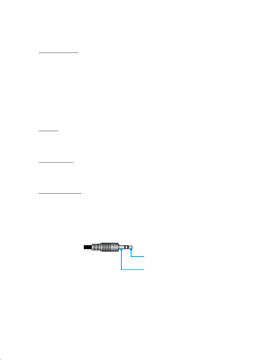
USING THE PROJECTOR
Brightness Level
Adjust the “Brightness Level” when the “Constant Brightness” and “Light Power
Adjustment” are selected in Light Mode.
When you select “Normal” or “Eco.”, you cannot select the “Brightness Level”.
Keypad LED Settings
Enable or disable the keypad LED.
Security
Set up security verication to protect the projector.
Security
Select On to protect the projector with a password. If the user enters incorrect
password three times, a message will pop up warning that the projector shuts
down in 10 seconds.
Security Timer
Specify the length of time the projector can be used without the password. Once
the timer counts to 0, the user must enter a password to use the projector. The timer
restarts every time the projector is turned on.
Change Password
Change the projector password.
12V Trigger
Use this function to enable or disable the trigger.
Note: 3.5mm TS type mini jack that outputs 12V 200mA (max.) for relay system control.
12V Trigger
Output
GND
High Altitude
This unit has a built-in air pressure sensor, and the “High Altitude Mode” will automatically
switch to “On” depending on the altitude of the installation location. When the High
Altitude Mode is switched to On, the cooling fan will rotate at high speed.
If the High Altitude Mode does not switch to On even when the altitude exceeds
1500 m/5000 ft, manually switch “High Altitude” to “On”.
85
Page 86

USING THE PROJECTOR
Audio Settings
Congure the projector built-in speaker settings.
Volume
Adjust the volume level.
Mute
Turn o or turn on the projector sound.
Note: Enabling the Audio Mute function will display the mute icon [ ] at the upper
right corner of the screen.
Audio Output
Select the audio output between Internal Speaker and Line Out.
Reset
Reset the audio settings to default factory values.
User Data
User can save the projector settings as user data and reload the settings later.
Save All Settings
Save all of the projector settings as user data. User can save up to 5 records.
Load All Settings
Load the previously saved user data.
86
Page 87
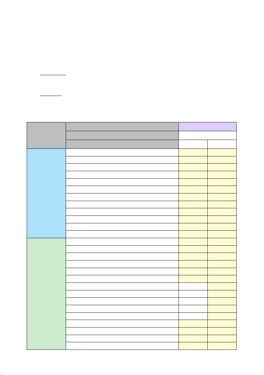
USING THE PROJECTOR
Reset
Reset the settings to factory default values.
Reset OSD
Reset OSD settings to default values.
Reset All
Reset all projector settings to default values.
Reset table
Category System
Reset path
Image
Display
SubCategory Reset
SubSubCategory Reset OSD Reset All
Color Mode
Brightness
Contrast
Sharpness
Gamma
White Balance
Color Space
Wall Color
Color Correction
Dynamic Contrast
Dynamic Range
3D Setup
Lens-Lens Shift Memory
Lens-Lens Lock
Aspect Ratio
Scale
On Screen Display
Background
Geometric Correction - V Keystone
Geometric Correction - H Keystone
Geometric Correction - 4-Corner
Geometric Correction - Warping
Geometric Correction - Grid Color
Input Signal Setting
Orientation
Freeze Screen
Test Pattern
87
Page 88
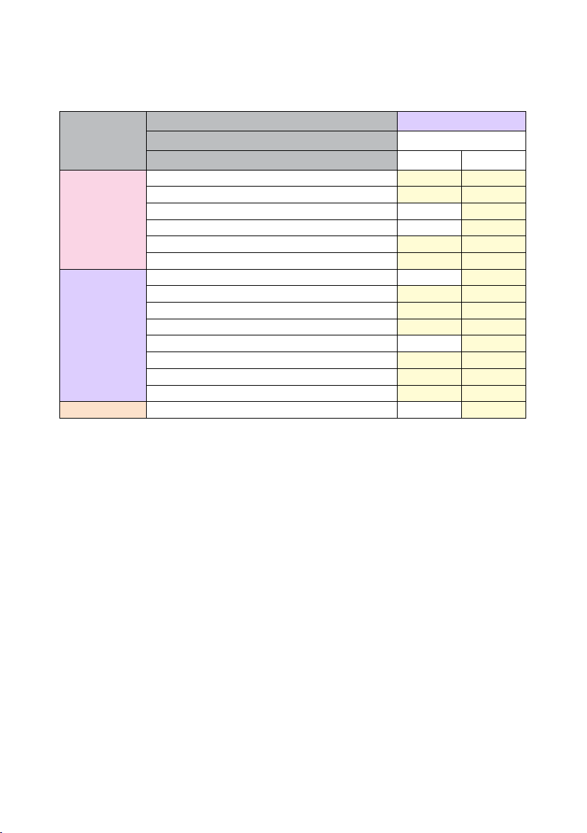
USING THE PROJECTOR
Category System
Reset path
Communication
System
Language
SubCategory Reset
SubSubCategory Reset OSD Reset All
Projector ID
Remote Setup
Network Setup
Control
Baud Rate
Command Format
Standby Mode
Power Settings
Light Source Setup
Keypad LED Settings
Security
12V Trigger
Audio Settings
User Data
88
Page 89

USING THE PROJECTOR
Information Menu
View the projector information about its status and settings. The projector information is
read only.
Submenus
• Projector
• System Status
• Control
• Communication
• Signal
• FW Version
Projector
Display the projector factory information.
Model Name
Display the projector model name.
Serial Number
Display the projector serial number.
System Status
Display the projector system status information.
Standby Mode
Display the current standby mode setting of the projector.
Total Projector Hours
Display the total projector usage hours.
Light Source Hours
Display the projector laser usage hours.
Ambient Temp.
Display the current ambient temperature of the projector.
System Temp.
Display the current system temperature of the projector.
89
Page 90

USING THE PROJECTOR
Control
Display projector control setting information.
Remote Code
Display the current remote code setting of the projector.
Crestron
Display the current Crestron on or o setting of the projector.
PJLink
Display the current PJLink on or o setting of the projector.
AMX
Display the current AMX on or o setting of the projector..
HTTP
Display the current HTTP on or o setting of the projector.
Communication
Display the projector communication setting information.
LAN Interface
Display the current LAN interface settings of the projector.
MAC Address
Display the projector MAC address information.
Network Status
Display the projector network connection status.
DHCP
Display the projector DHCP settings.
IP Address
Display the current IP address of the projector.
Subnet Mask
Display the current Subnet Mask of the projector.
Gateway
Display the current Gateway of the projector.
DNS 1 / DNS 2
Display the current DNS1 and DNS2 address of the projector.
90
Page 91

USING THE PROJECTOR
Signal
Display the projector input signal information.
Input Signal
Display the current input signal of the projector.
Resolution
Display the resolution of the current input signal source of the projector.
Signal Format
Display the format of the current input signal source of the projector.
Pixel Clock
Display the pixel clock of the projector’s current input signal source.
Horz. Refresh
Display the horizontal refresh frequency of the projector’s current input signal
source.
Vert. Refresh
Display the vertical refresh frequency of the projector’s current input signal source.
Color Space
Display the color space of the projector’s current input signal source.
FW Version
Display the projector rmware version information.
Main / F-MCU / A-MCU / LAN / Formatter / HDBaseT Version
Display the projector rmware version information.
91
Page 92

USING THE PROJECTOR
Language Menu
Learn how to select the language for the OSD (on-screen display) menu of the projector.
Submenus
• Language
Language
Select a language for the OSD menu. The available languages are English, German,
French, Italian, Spanish, Swedish, Korean, Polish, Hungarian, Russian, Greek,Turkish,
Portuguese, Arabic, Czech, Traditional Chinese, Norwegian, Dutch, Japanese, Simplied
Chinese, and Thai.
92
Page 93

ADDITIONAL INFORMATION
Compatible Resolutions
Horizontal : 15 - 255KHz
Vertical : 23 – 120Hz, 240Hz
Digital
Signal
VGA 640 x 480 4:3 60
SVGA 800 x 600 4:3 60
XGA 1024 x 768 4:3 60
WXGA 1280 x 768 15:9 60 Only EDID1.4 support
WXGA 1280 x 800 16:10 60
SXGA 1280 x 960 4:3 60
SXGA 1280 x 1024 5:4 60
FWXGA 1360 x 768 16:9 60 Only EDID1.4 support
FWXGA 1366 x 768 16:9 60 Only EDID1.4 support
WXGA+ 1440 x 900 16:10 60
HD+ 1600 x 900 16:9 60
UXGA 1600 x 1200 4:3 60
WSXGA+ 1680 x 1050 16:10 60
WUXGA 1920 x 1200 16:10 60 Reduce Blanking
UWFHD 2560 x 1080 21:9 24/25/30/50/60 Only EDID 2.0 support
480P 720 x 480 4:3 60
576p 720 x 576 5:4 50
720p 1280 x 720 16:9 50/60/120
1080p 1920 x 1080 16:9 24/25/30/50/60/
2160p 3840 x 2160 16:9 24/25/30/50/60 EDID1.4 supports up
4K2K 4096 x 2160 17:9 24/25/30/50/60 EDID1.4 supports up
Resolution
(dots)
Aspect Ratio
Refresh Rate
(Hz)
120/240
Note
Only EDID2.0 supports
1080P240
to 2160P 30Hz
to 4K2K 24Hz
93
Page 94

ADDITIONAL INFORMATION
3D
Signal
720p 1280 x 720 16:9 50/60 Top - and - Bottom
1080p 1920 x 1080 16:9 24/60 Top - and - Bottom
1080p 1920 x 1080 16:9 24/50/60 Side- by-Side (Half )
720p 1280 x 720 16:9 50/60 Frame packing
1080p 1920 x 1080 16:9 24 Frame packing
XGA 1024 x 768 4:3 120 Frame Sequential
720p 1280 x 720 16:9 120 Frame Sequential
1080p 1920 x 1080 16:9 60/120 Frame Sequential
WUXGA 1920 X 1200 16:10 60 Frame Sequential
Resolution
(dots)
Aspect Ratio
Refresh Rate
(Hz)
Note
94
Page 95
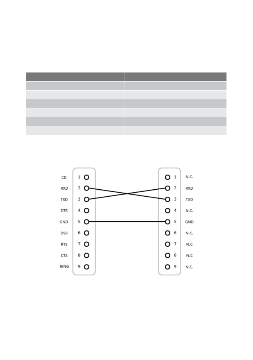
ADDITIONAL INFORMATION
RS232 Port Setting and Signals Connection
RS232 Port Setting
Items Method
Communication Method Asynchronous Communication
Baud Rate 115200
Data Bits 8 bits
Parity None
Stop Bits 1
Flow Control None
RS232 Signals Connection
Computer COM Port
(D-Sub 9-pin connector)
Note: RS232 shell is grounded.
Projector COM Port
(D-Sub 9-pin connector)
95
Page 96
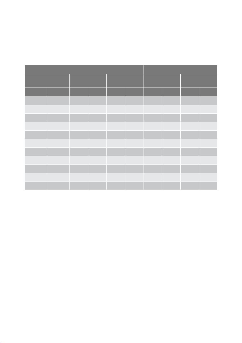
ADDITIONAL INFORMATION
Image Size and Projection Distance
The size of projected images is 60 ~ 300 inches (1.64 ~ 13.35 m)
Screen Size 16:9 (Wx H) Projector Distance
Diagonal Length
of Image
inch m inch m inch m inch m inch m
60 1.52 52.3 1.33 29.4 0.75 64.6 1.64 103.5 2.63
70 1.78 61.0 1.55 34.3 0.87 75.7 1.92 121.1 3.08
80 2.03 69.7 1.77 39.2 1.00 86.8 2.20 138.7 3.52
90 2.29 78.4 1.99 44.1 1.12 97.9 2.49 156.3 3.97
100 2.54 87.2 2.21 49.0 1.25 109.0 2.77 173.9 4.42
120 3.05 104.6 2.66 58.8 1.49 131.2 3.33 209.1 5.31
150 3.81 130.7 3.32 73.5 1.87 164.5 4.18 261.8 6.65
180 4.57 156.9 3.98 88.2 2.24 197.8 5.03 314.6 7.99
200 5.08 174.3 4.43 98.0 2.49 220.0 5.59 349.8 8.88
250 6.35 217.9 5.53 122.5 3.11 275.6 7.00 437.7 11.12
300 7.62 261.5 6.64 147.1 3.74 331.1 8.41 525.7 13.35
Width Height Wide Tele
96
Page 97
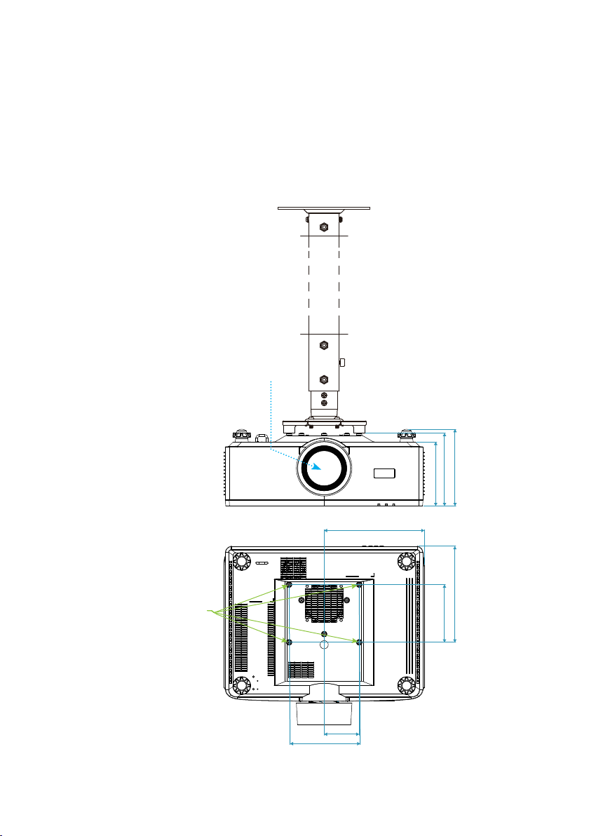
ADDITIONAL INFORMATION
Ceiling Mount Installation
1. To prevent damage to your projector, please use ceiling mount.
2. If you wish to use a third party ceiling mount kit, please ensure the screws used to
attach a mount to the projector meet the following specications:
• Screw type: M4*4
• Minimum screw length: 8 mm
Note: The minimum length of the screw
is 8mm, excluding the thickness of
the ceiling mount.
Lens
Mounting holes
M4L8-4x
97
170.0 (6.7”)
85.0mm (3.3”)
243.0mm (9.6”)
186.0mm (7.3”)
176.5mm (6.9”)
155.0mm (6.1”)
233.0mm (9.2”)
140.0mm (5.5”)
Page 98
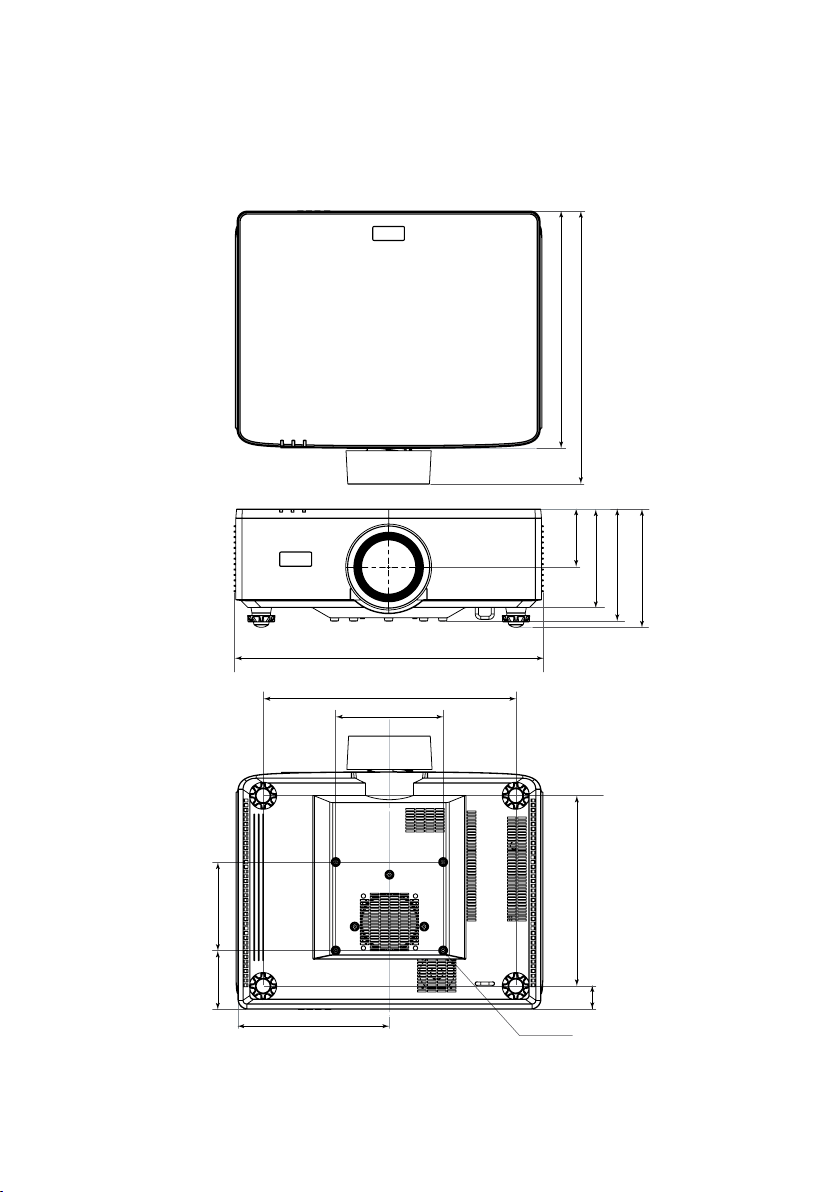
ADDITIONAL INFORMATION
External Dimensions
486.0mm (19.1”)
376.0mm (14.8”)
432.5mm (17.0”)
(3.6”)
91.3mm
155.0mm (6.1”)
176.5mm (6.9”)
186.0mm (7.3”)
(5.5”)
140.0mm
(3.7”)
93.0mm
240.0mm (9.4”)
400.0mm (15.7”)
170.0 (6.7”)
98
4-M4×L8
301.3mm (11.9”)
(1.4”)
36.7mm
Page 99

ADDITIONAL INFORMATION
Troubleshooting
If you experience a problem with your projector, please refer to the following information.
If a problem persists, please contact your local reseller or service center.
Image problems
No image appears on-screen
• Ensure all the cables and power connections are correctly and securely connected as
described in the Setup and Installation section.
• Ensure the pins of connectors are not crooked or broken.
• Ensure that the Shutter feature is not turned on.
Image is out of focus
• Press the FOCUS button on the remote control or projector keypad. Then press the p
or q button to adjust the focus until the image is sharp and legible.
• Make sure the projection screen is between the required distance from the projector.
(Please refer to Image size and projection distance page 96).
The image is stretched when displaying 16:9 DVD title
• When you play anamorphic DVD or 16:10 DVD, the projector will show the best image
in 16:9 format on projector side.
• If you play 4:3 format DVD title, please change the format as 4:3 in projector OSD.
• Please setup the display format as 16:9 (wide) aspect ratio type on your DVD player.
Image is too small or too large
• Press the ZOOM button on the remote control or projector keypad . Then press the p
or q button to adjust the projected image size.
• Move the projector closer to or further from the screen.
• From the OSD menu, select Display Aspect Ratio to change the aspect ratio.
Image has slanted sides:
• If possible, reposition the projector so that it is centered on the screen and below the
bottom of the screen.
• Press the Geometric. buttons on the remote control to adjust distortions in projected
images.
Image is reversed
• From the OSD menu, select Display Orientation Rear to reverse the image so
you can project from behind a translucent screen.
99
Page 100

ADDITIONAL INFORMATION
Other problems
The projector stops responding to all controls
• If possible, turn o the projector, then unplug the power cord and wait at least
20 seconds before reconnecting power.
Remote control problems
If the remote control does not work
• Check that the operating angle of the remote control is pointed within ±30° to the IR
receivers on the projector.
• Make sure there are not any obstructions between the remote control and the
projector. Move to within 6 meters (19.7 feet) of the projector.
• Make sure batteries are inserted correctly.
• Replace batteries if they are exhausted.
100
 Loading...