

Page 1
XL-UH242
SERVICE MANUAL
No. S3607XLUH242/
MICRO COMPONENT SYSTEM
MODEL
XL-UH242 Micro Component System consisting of
XL-UH242 (main unit) and CP-UH242 (speaker system).
• In the interests of user-safety (Required by safety regulations in some countries) the set should be restored to its
original condition and only parts identical to those specified
be used.
This Service Manual is for XL-UH242,which is a minor modification model of the XL-UH240. This Service Manual, therefore,
describes only the changed points from the Service Manual. Please refer to
together with this Service Manual.
the XL-UH240 Service Manual (S1601XLUH240/)
XL-UH242
DIFFERENCE BETWEEN XL-UH240 AND XL-UH242
REF.
NO.
P.W.B ASSEMBLY (Not Replacement Item)
CABINET PARTS
PART NO. PART NO.
XL-UH240 XL-UH242
92 L P WB6 2 74L E D SPW B - D NI L LED (P.W.B Only)
DESCRIPTION
CODE
20 1
20 1 - 3
20 5
20 8
20 9
22 5
ACCESSORIES/ PACKING PARTS
Parts marked with " " are important for maintaining the safety of the set. Be sure to replace these parts with specified
ones for maintaining the safety and performance of the set.
CC A B A64 7 5AW 0 1
HD E C QA2 4 0AW S A
GC A B -A0 3 5AW S A
GI T A SA1 4 0AW S A
GI T A SA1 4 1AW S A
TS P C -A5 6 1AW Z Z
TI N S EA1 2 1AW Z Z
TI N S ZA1 8 1AW Z Z
CC A B A64 7 8AW 0 1
HD E C QA2 6 8AW S A
GC A B -A0 3 5AW S B
GI T A SA1 4 0AW S B
GI T A SA1 4 1AW S B
TS P C -A5 6 6AW Z Z
TI N S EA1 2 2AW Z Z
TI N S ZA1 8 2AW Z Z
– 1
Front Panel Assembly
Panel, FL Display
Top Cabinet
Side Panel, Left
Side Panel, Right
Label, Specification
Operation Manual
Quick Guide
This document has been published to be used for after
sales service only.
The contents are subject to change without notice.
AY
AC
AL
AD
AD
BB
AF
BH
Page 2
XL-UH242
DIFFERENCE BETWEEN XL-UH240 AND XL-UH242
REF.
NO.
PART NO. PART NO.
XL-UH240 XL-UH242
SPEAKER BOX PARTS
90 1
90 2
90 4
SP 1 ,2
SP 3 ,4
90 7
90 8
90 9
GB O X SA1 2 0AW 0 1
CP N L SA0 5 6AW 0 1
TS P C -A5 6 2AW Z Z
RS P - ZA1 7 3AW Z Z
RS P - ZA1 7 4AW Z Z
XE S Y 730 P 100 0 0
NI L
NI L
SPEAKER BOX PARTS
(CP-UH242)
A
909x4
908
B
902
GB O X SA0 9 9AW 0 1
HP N L SA0 3 6AW S C
TS P C -A5 7 3AW Z Z
RS P - ZA0 8 4AW Z Z
RS P - ZA0 8 5AW Z Z
NI L
CW A K PA0 1 0AW 0 2
LH L D Z80 0 1AW S A
DESCRIPTION
Wooden Box Ass'y
Front Panel
Label, Specification
Woofer
Tweeter
Screw, M3x10mm
Net Frame Ass'y
Cathing Holder
C1,2
Capacitor
RED
TWEETER
SP3(L-CH)
SP4(R-CH)
BK
RED
CODE
BF
AU
AQ
AZ
AT
AS
AD
RED
BK
WOOFER
SP1(L-CH)
SP2(R-CH)
904
TWEETER
SP3(L-CH)
SP4(R-CH)
WOOFER
SP1(L-CH)
SP2(R-CH)
C1,2
Capacitor
3.3µF,100V
901
C
D
906x2
SP3,4
E
905x4
903x4
F
SP1,2
G
1
2 3 4 5 6
7
2
Page 3

ACCESSORIES
[]
XL-UH242
PACKING METHOD
UNIT
Label,WMA
TLABZA267AWZZ
Label,Energy Star
TLABZA149AWSA
TLABZA366AWZZ
Polyethylene Bag,Unit
SSAKH0094AWZZ
Packing Add.,Unit,Top/Bottom
SPAKAA119AWZZ
Label,POP
FM Antenna
Polyethylene Bag,Accessories
SSAKAA006AWZZ
Bottom
AM Loop
Antenna
Operatio
k Guide
Quic
Remot
n Manual
Front Speaker(L/R)
Sheet,Speaker
A
e Control
SPAKZA012AWZZ
Polyethylene Bag,Speaker
SSAKHA060AWZZ
Packing,Add.,
Fron
t Speaker,Top/Bottom
SPAKAA067AWZZ
B
: Not Replacement Item
Packing
Case
SPAKCA337AWZZ
Front of Packing Case
B
F
F
R
R
O
O
TN
TN
A
3
Page 4

XL-UH242
SPECIFICATION
rek
epS
a
(CP-UH242)
epyT metsys
u
i mumix
M
a
w
o
p
e
R
eta
emi
D )mm 581(
gieW
p
n
r
d
i
adepmI sm
th
t
w
re
tu
o
n
p
p
ecn
o
isn
sn
t
hgil e
p
yaw-2
y
"
2
8
1
9
0
6
H
.6
t
)mc 5(
1
(
8
1-5
/
"
0
W
W
ho
tpeD
w
)mc 3
1-7 :htdiW
"4/
1-0
1 :thgie
"4/
-9 :h
1
gk 8.2( .sbl 1
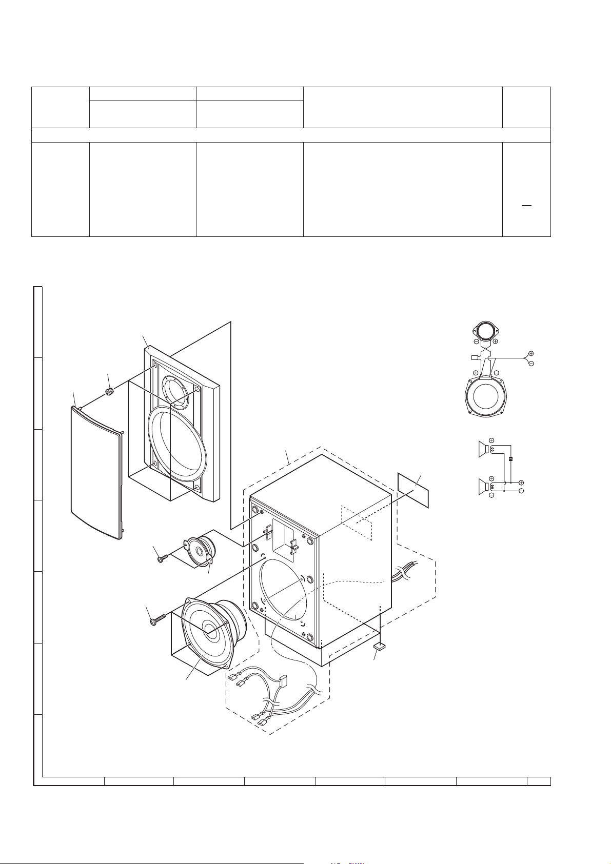
DISASSEMBLY
(CP-UH242)
ps pu-t
ekae
r
reteew
ref
o
o
62(
)m
m 0
m 032( "16/
)m
)
hc
ae/
1 Woofer/
Tweeter
1. Net Frame................(A1) x1
2. Front Panel...............(A2) x1
3. Screw.......................(A3) x6
Front Panel
(A2)x1
NetFrame
(A1)x1
8
(A3)x2
ø3x10mm
Tweeter
(A3)x4
ø4x16mm
Woofer
Screwdriver
Figure 8
SHARP CORPORATION
Sharp-Roxy Corporatio
Sungai Petani, Kedah
Malaysi
a
Printed in Malaysia
A0306-210MX•RR•M
n
,
 Loading...