

Page 1
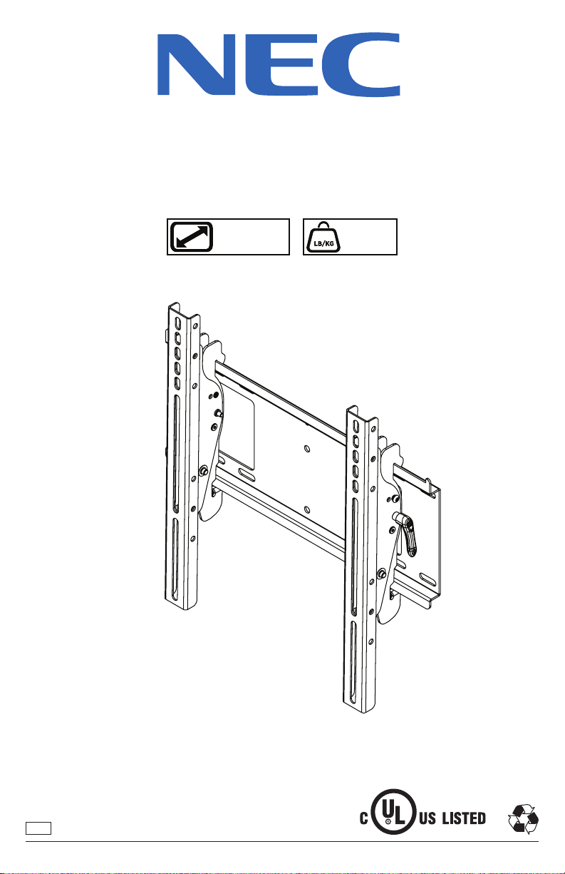
WMK-3298T
32" - 98"
(82 - 249 cm)
MAX
210 lb
(95 kg)
ENG
1
2019-12-18 #:126-9246-3 (2020-03-02)
Page 2
WARNING
ENG - This product is designed to be installed on wood stud, solid concrete or cinder block walls. Hardware is
included for wood stud, solid concrete and cinder block installation. Before installing make sure the supporting
surface will support the combined load of the equipment and hardware. Screws must be tightly secured. Do
not overtighten screws or damage can occur and product may fail. Never exceed the Maximum Load Capacity.
Always use an assistant or mechanical lifting equipment to safely lift and position equipment. This product is
intended for indoor use only. Use of this product outdoors could lead to product failure or personal injury. Be
ENG
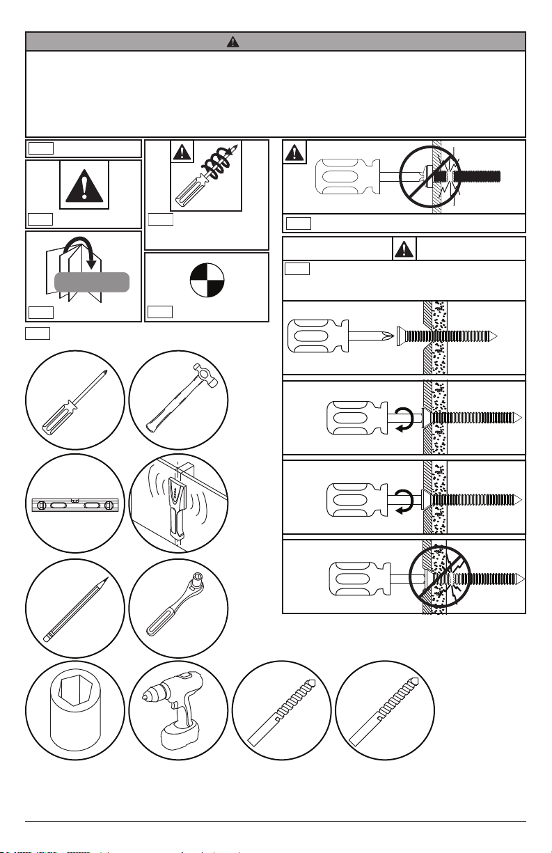
Symbols
x3
Screws must get at
ENG
WARNING
#
ENG
Skip to step.
ENG
Tools Needed for Assembly.
ENG
least three full turns
ENG
Display center.
Do not overtighten screws.
ENG
To properly tighten screws: Tighten until screw
ENG
head makes contact, then tighten another 1/2
turn. Do not overtighten screws.
1
2
3/8"
(10mm)
5/32"
(4mm)
3
+1/2
4
(8mm)
2
2019-12-18 #:126-9246-3 (2020-03-02)
Page 3
ENG
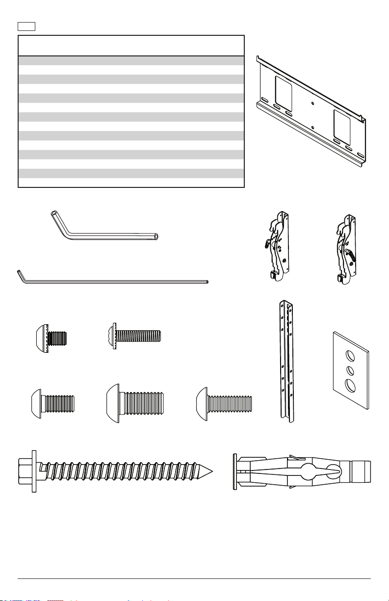
Parts (Before beginning, make sure you have all parts shown below).
Parts List
A wall plate 1 203-1037
B left tilt bracket 1 203-1039
C right tilt bracket 1 203-1038
D #14 x 2.5 wood screw 5S1-015-C03
E concrete anchor 590-0320
F 4mm allen wrench 1
G 4 520-1050
H 4 520-1132
I multi washer 4
J M8 x 15mm socket pin screw 4
K 8 510-1114
L extension brackets 2
M 18 x 1mm security allen wrench 1
N 4 510-1087
(1)
F
4mm allen
wrench
(1)
M
18 x 1mm allen wrench
Part #Description Qty
B (1)
left tilt bracket
A (1)
wall plate
right tilt bracket
C
(1)
(8)
K
(4)
G
D
#14 x 2-1/2" wood screw
N
J
M8 x 15mm
(6)
(4)
(4)
3
(4)
H
(2)
L
extension
bracket
(6)
E
8mm concrete anchor
2019-12-18 #:126-9246-3 (2020-03-02)
(4)
I
multi washer
Page 4
1
ENG
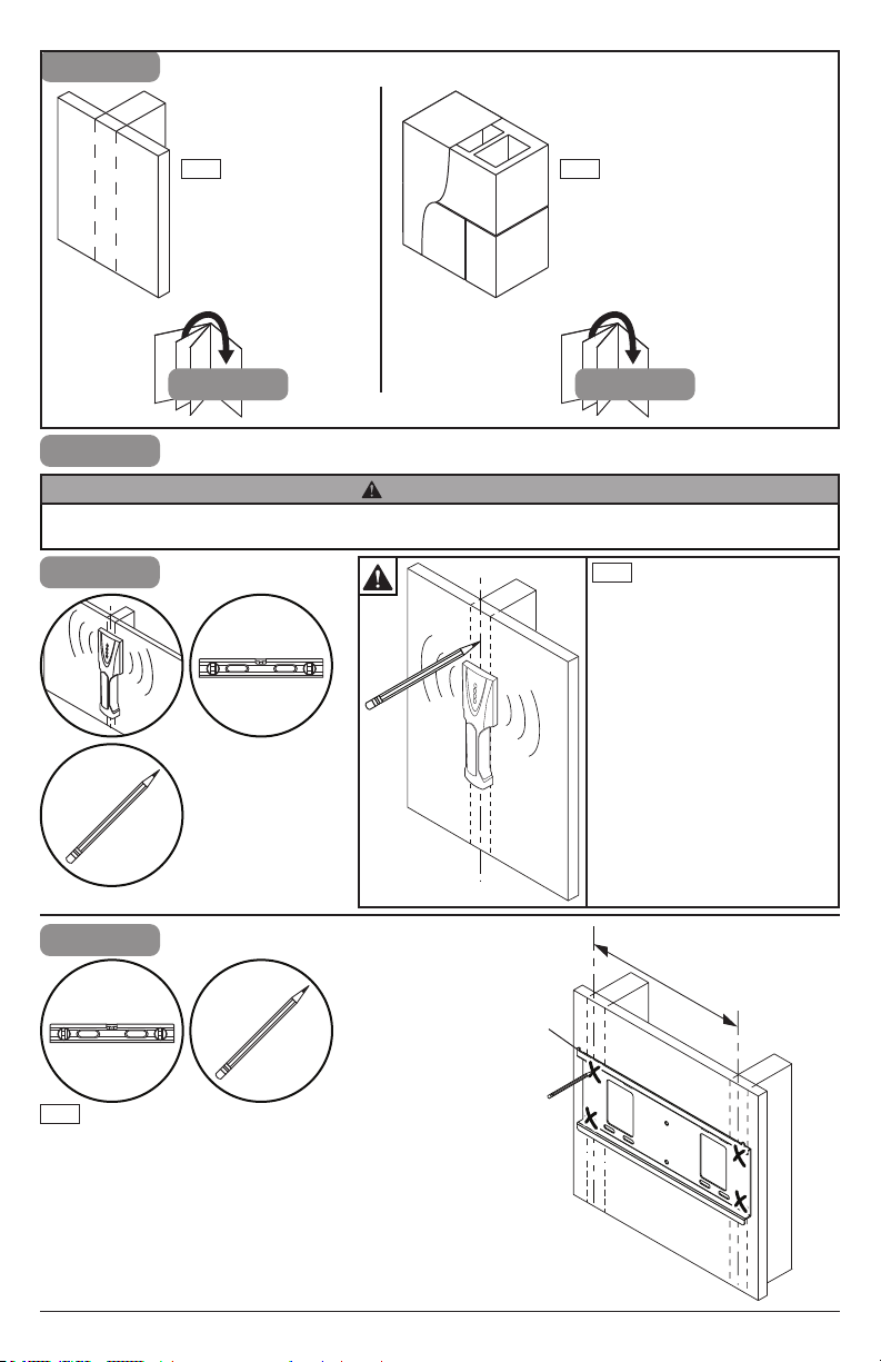
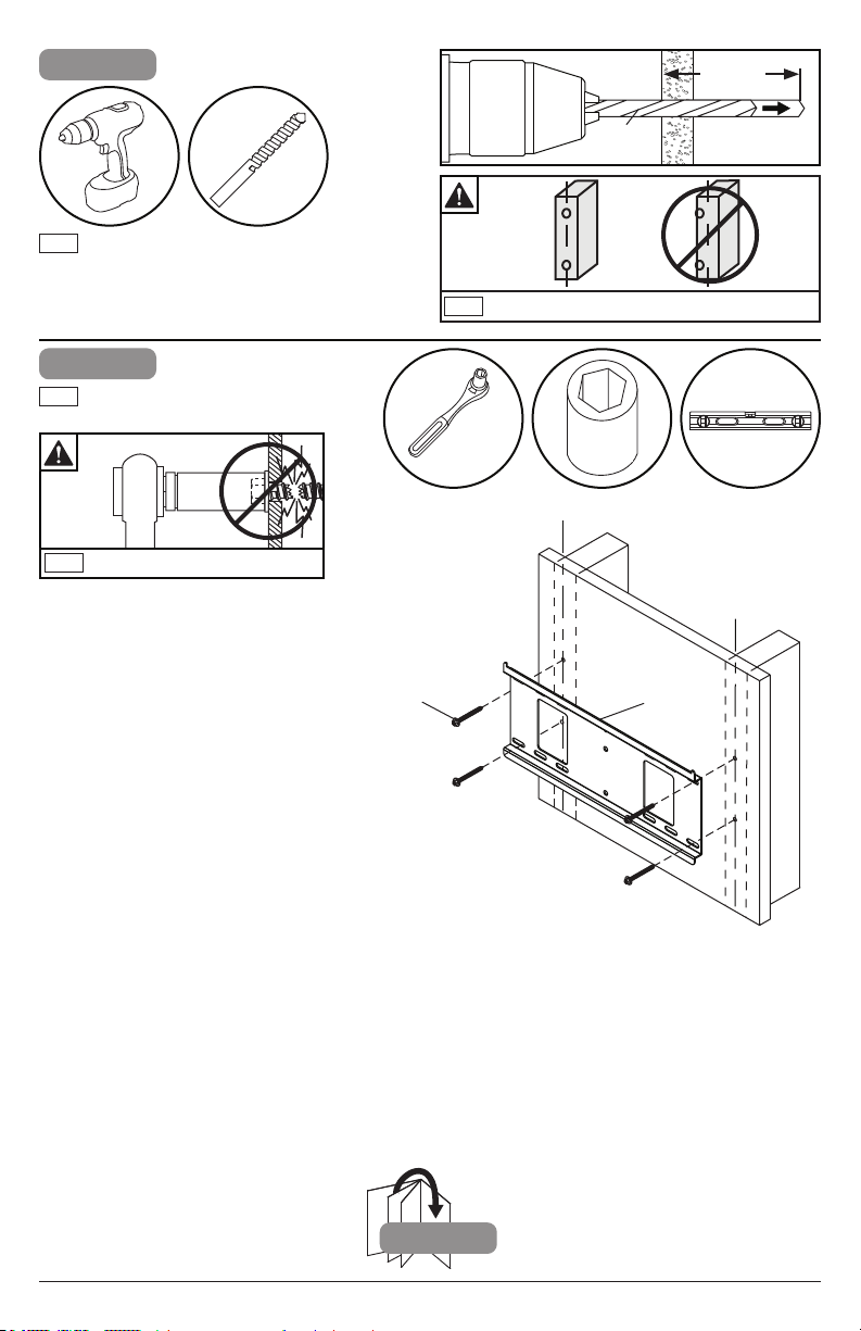
Wood stud wall.
1a
ENG
Concrete/Cinder block.
1b
1a
WARNING
ENG - When installing Peerless wall mounts on a wood stud wall covered with gypsum board (drywall), verify that
the wood studs are a minimum of 2" x 4" nominal size. Do not install over gypsum board thicker than 5/8".
ENG
1a-1
mark stud center lines.
1a-2
ENG
Level wallplate. Mark mounting holes on stud
center lines.
(41cm)
A
4
2019-12-18 #:126-9246-3 (2020-03-02)
Page 5
1a-3
2.5"
5/32"
(4mm)
ENG
Drill mounting holes into supporting surface
1a-4
Level wallplate. Install using wood
ENG
screws provided.
ENG
Maximum 80 in. • lb (9 N.M.).
D (4)
5/32"
(4mm)
ENG
Mounting hole must center on stud.
3/8"
(10mm)
A
5
2
2019-12-18 #:126-9246-3 (2020-03-02)
Page 6
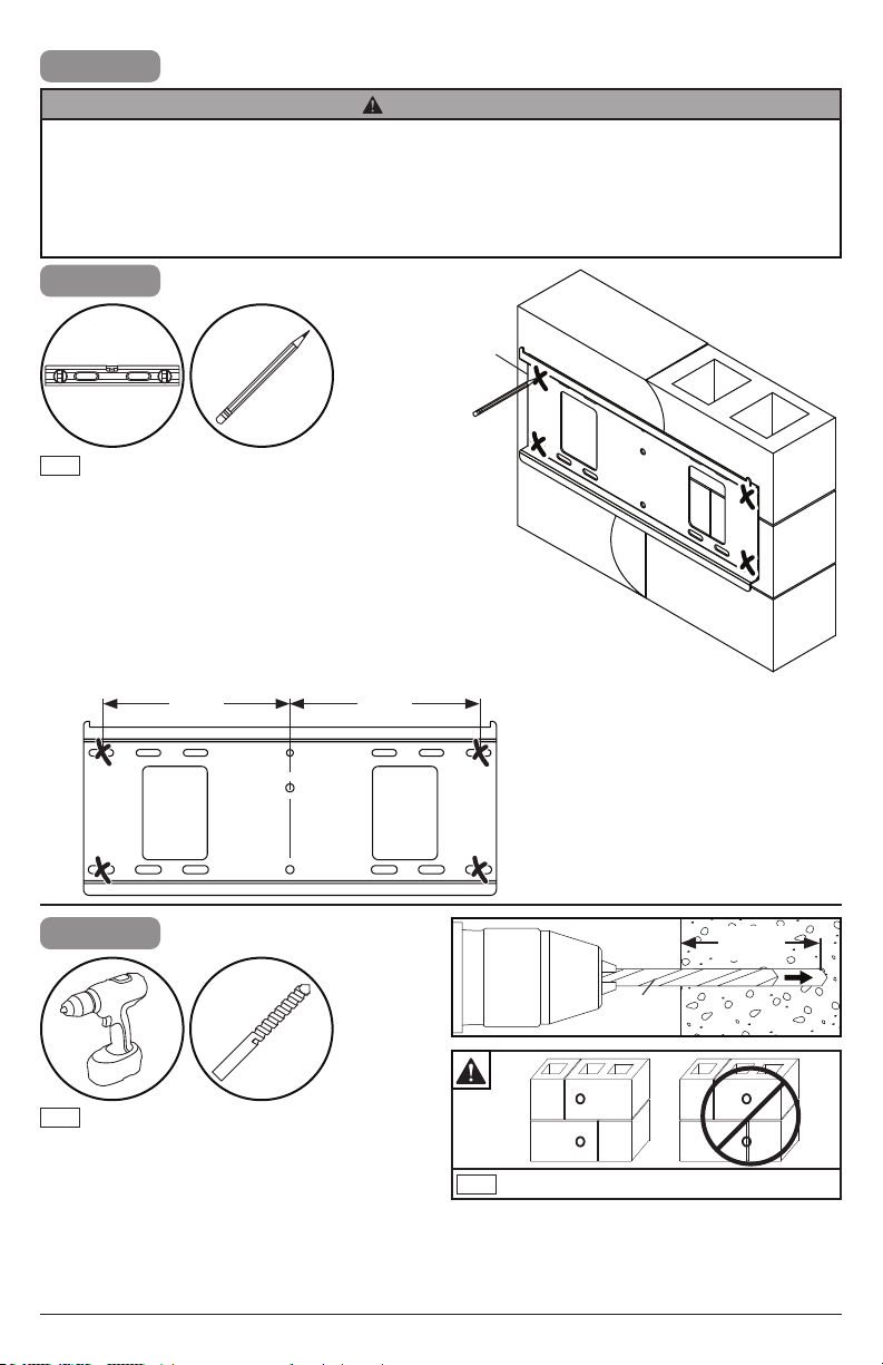
1b
WARNING
ENG - When installing Peerless wall mounts on a concrete wall, the wall must be at least 8" thick with a minimum
compressive strength of 2000 psi. When installing Peerless wall mounts on a cinder block wall, the cinder blocks
Be sure to mount in a solid part of the block, generally 1" (25 mm) minimum from the side of the block. It is
suggested that a standard electric drill on slow setting is used to drill the hole instead of a hammer drill to avoid
breaking out the back of the hole when entering a void or cavity. Never attach concrete expansion anchors to
1b-1
A
ENG
Level wallplate. Mark mounting holes.
8"
(20cm)
1b-2
(8mm)
ENG
Drill mounting holes into supporting surface
8"
(20cm)
2.5"
(8mm)
ENG
Do not drill into mortar joints.
6
2019-12-18 #:126-9246-3 (2020-03-02)
Page 7
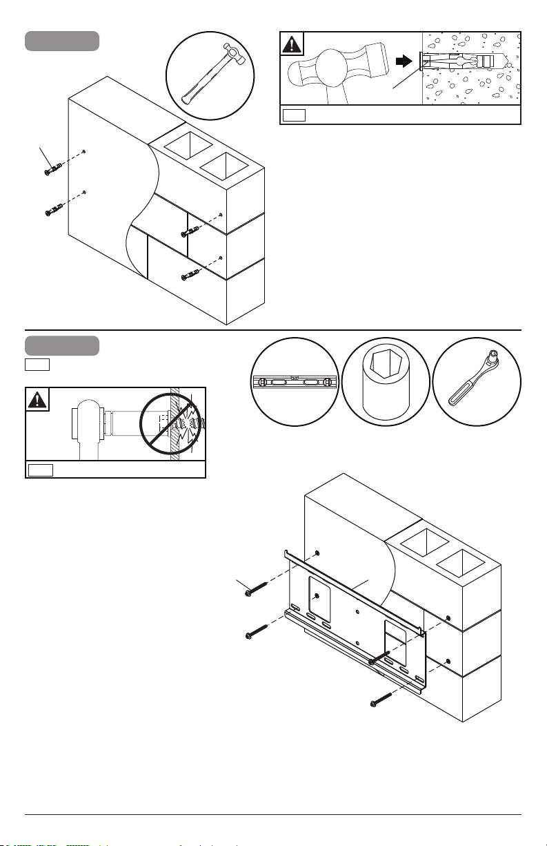
1b-3
E (4)
1b-4
ENG
Level wallplate. Install using concrete
anchors and wood screws provided.
E
ENG
3/8"
(10mm)
ENG
Maximum 80 in. • lb (9 N.M.).
D (4)
A
7
2019-12-18 #:126-9246-3 (2020-03-02)
Page 8
2
ENG
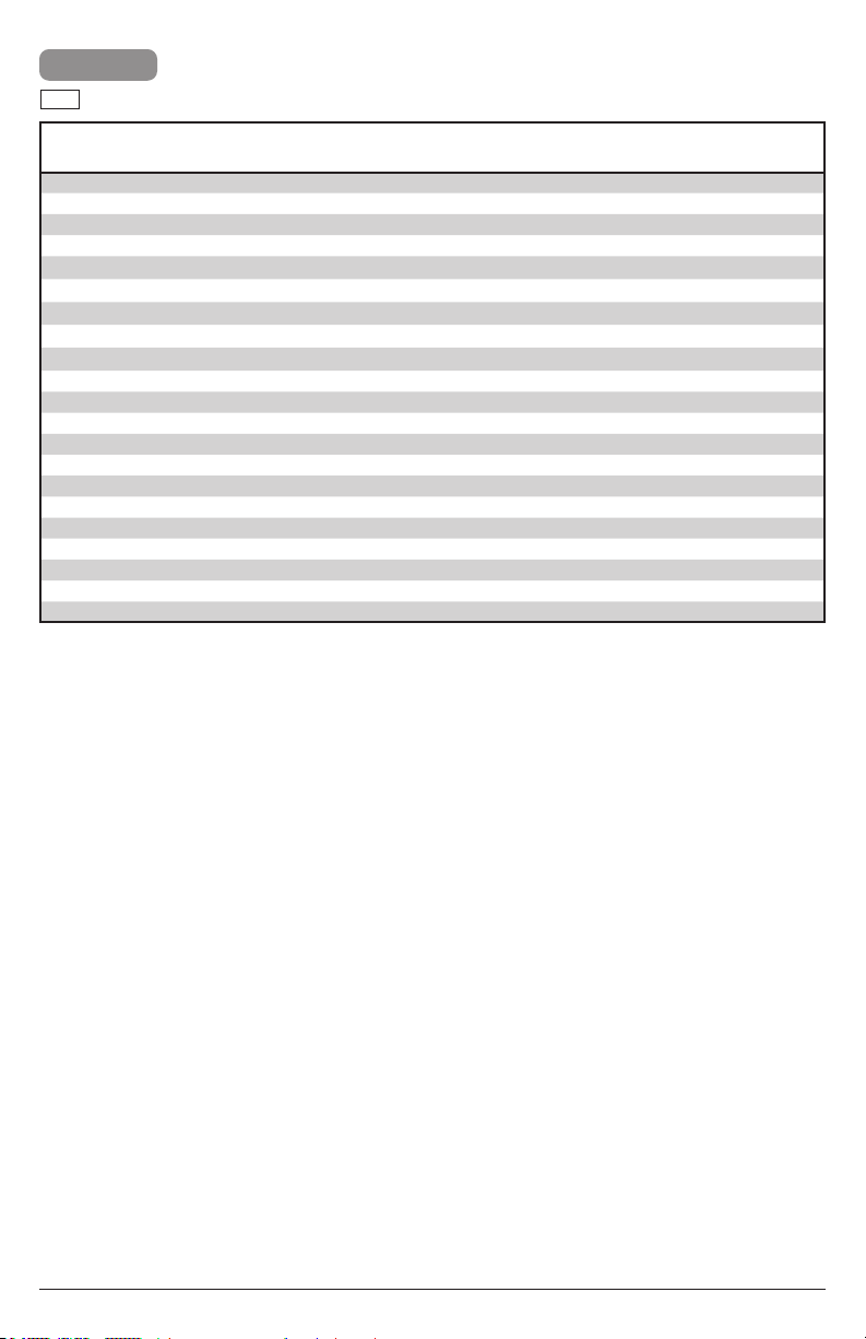
Use chart to determine orientation, vesa pattern and hardware for your display.
Display Model # Orientation Vesa
E327 landscape 100x100
E437Q landscape 200x200
E507Q landscape 400x200
E557Q landscape 400x200
E657Q landscape 400x200
IB554Q-2.1 landscape 300x300
IB654Q-2.1 landscape 400x400 M8 x 15
IB754Q-2.1 landscape 400x400 M8 x 15
IB864Q-2.1 landscape 400x400 M8 x 15
C431 landscape/portrait 300x300
C501 landscape/portrait 300x300
C551 landscape/portrait 300x300
C651Q/V654Q landscape/portrait 400x400 M8 x 15
C751Q/V754Q landscape/portrait 400x400 M8 x 15
C861Q/V864Q landscape/portrait 400x400 M8 x 15
C981Q/V864Q landscape/portrait 400x400 M8 x 15
P404/V404 landscape/portrait 300x300
P484/V484 landscape/portrait 300x300
P554/V554 landscape/portrait 300x300
V323-3 landscape/portrait 200x200
V554Q landscape/portrait 300x300
Mounting Hardware
8
2019-12-18 #:126-9246-3 (2020-03-02)
Page 9
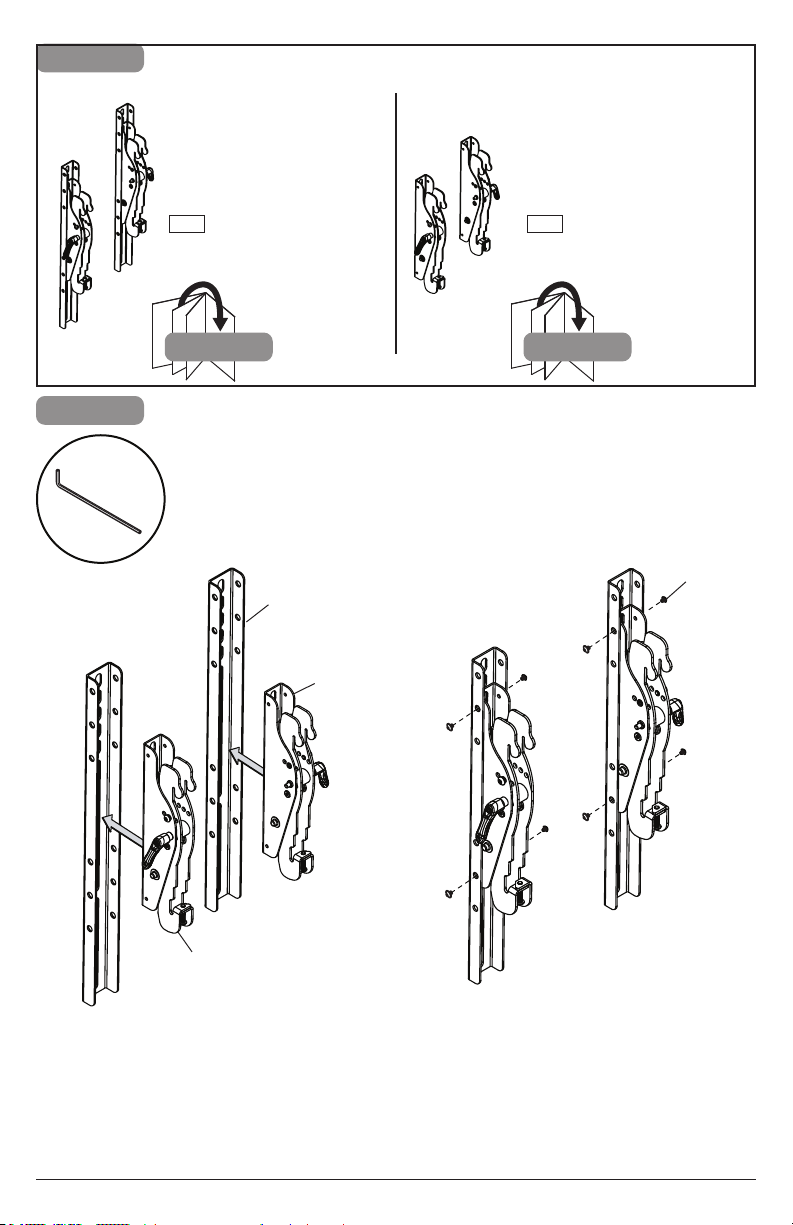
3
VESA 100 X 100:VESA 300 X 300:
3a
F
VESA 400 X 400:
ENG
With extension brackets.
L (2)
C
VESA 200 X 200:
VESA 400 X 200:
ENG
Without extension brackets.
3b3a
K (8)
B
9
2019-12-18 #:126-9246-3 (2020-03-02)
Page 10
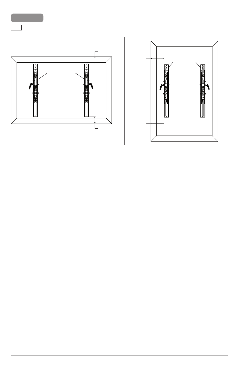
3a-1
ENG
Center adaptor brackets vertically on back of
screen.
B
C
X
X
X
B C
X
10
2019-12-18 #:126-9246-3 (2020-03-02)
Page 11
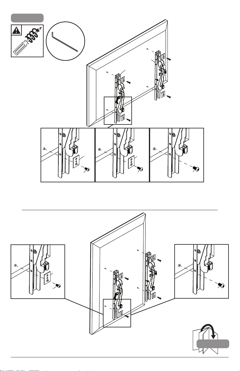
3a-2
F
x3
EE437Q, I B554Q-2.1,
C431, C501, C551, P404/
V404, P484/V484, P554/
V554, V323-3, V554Q
B
I (4)
I (4)
G (4) H (4)
E507Q, E557Q, E657Q
C
J (4)
IB654Q-2.1, I B754Q-2.1,
IB864Q-2.1, C651Q/V654Q,
C751Q/V754Q, C861Q/
V864Q, C981Q/V864Q
I (4)
G (4)
C431, C501, C551,
P404/V404, P484/
V484, P554/V554,
V323-3, V554Q
11
J (4)
C651Q/V654Q,
C751Q/V754Q,
C861Q/V864Q,
C981Q/V864Q
4
2019-12-18 #:126-9246-3 (2020-03-02)
Page 12
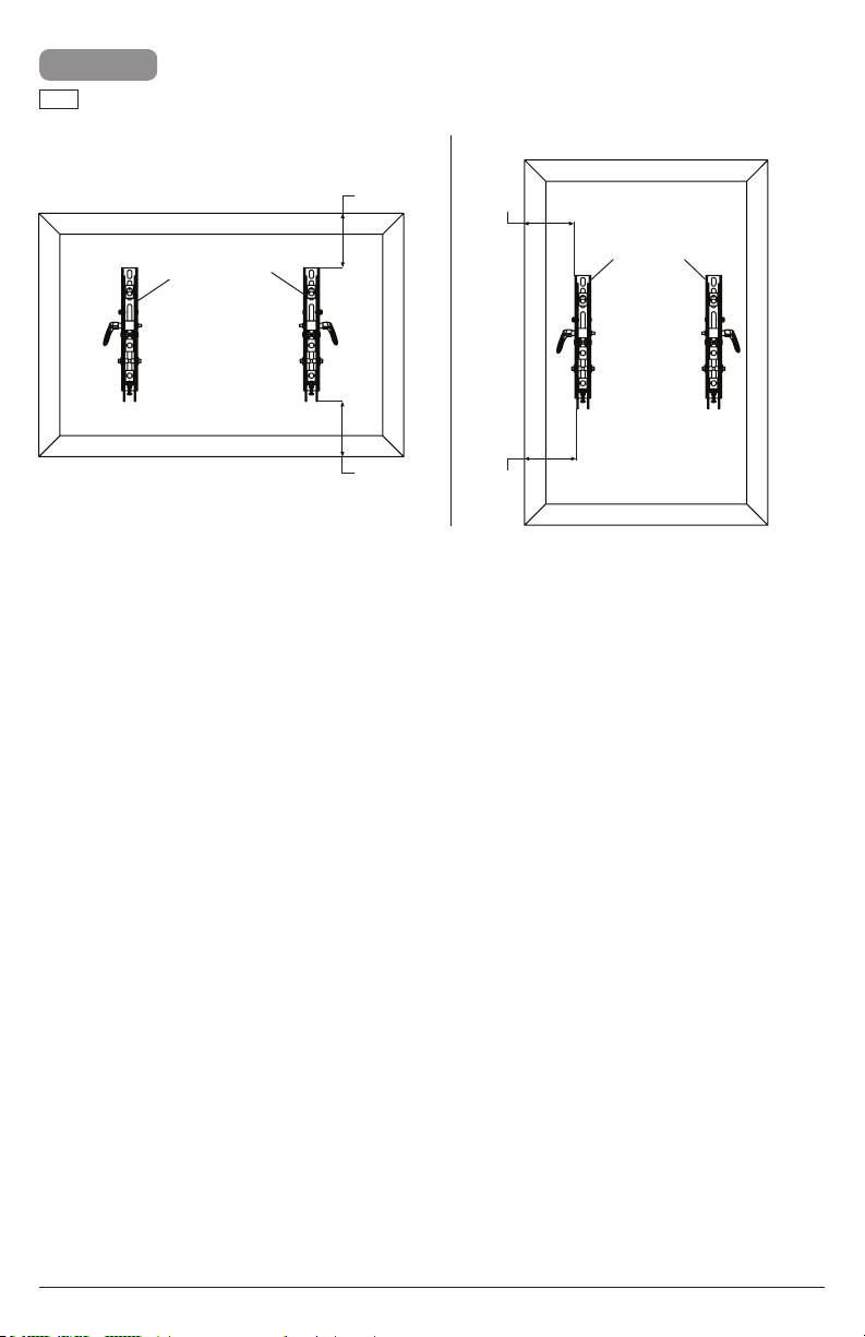
3b
ENG
Center adaptor brackets vertically on back of
screen.
B
C
X
X
X
B C
X
12
2019-12-18 #:126-9246-3 (2020-03-02)
Page 13
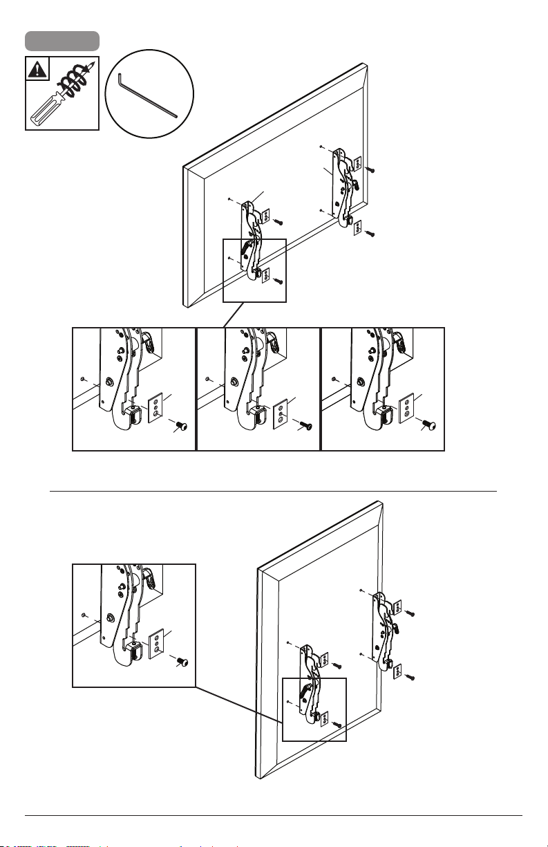
3b-1
x3
F
C
B
G (4)
V323-3
I (4)
I (4)
G (4)
N (4)
E327EE437Q, V323-3
I (4)
I (4)
H (4)
E507Q, E557Q, E657Q
13
2019-12-18 #:126-9246-3 (2020-03-02)
Page 14
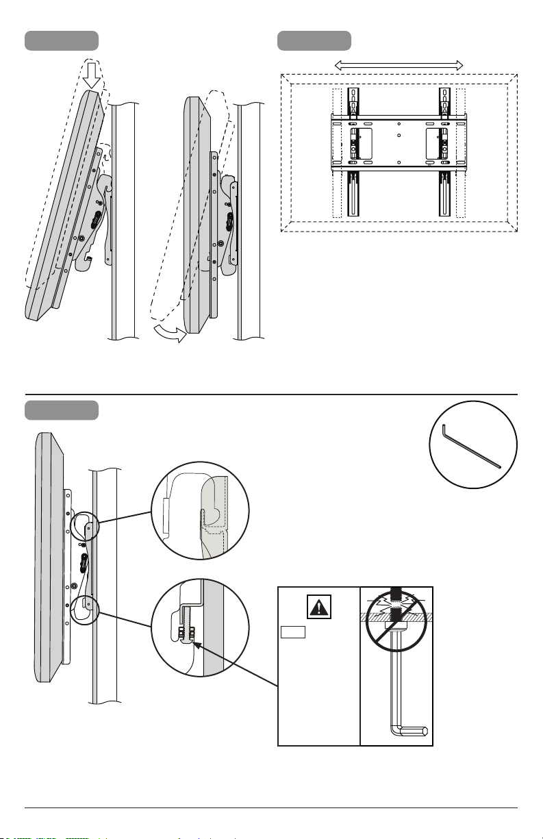
4
6
5
M
14
ENG
Tighten.
2019-12-18 #:126-9246-3 (2020-03-02)
Page 15
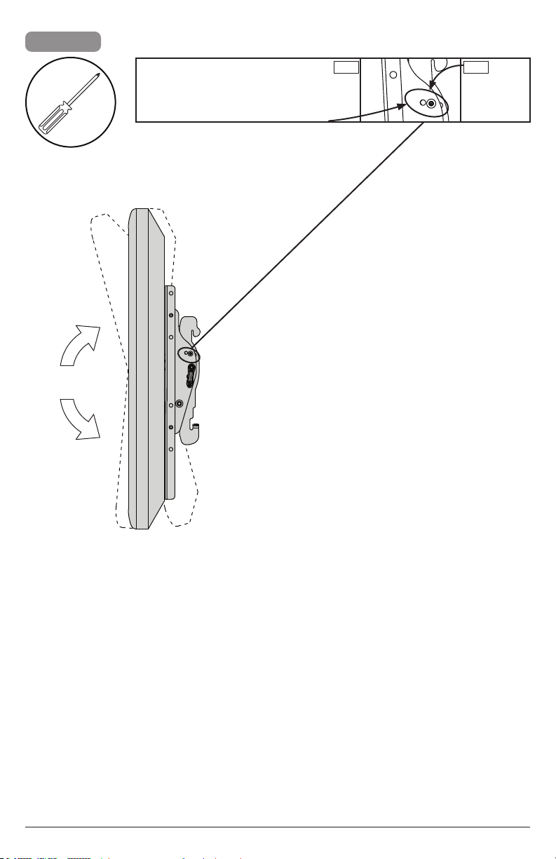
7
+15°,-5°
Pre-set tilt positions of -5°, 0°, 5°, 10° or 15°.
ENG
ENG
Tighten.
15
2019-12-18 #:126-9246-3 (2020-03-02)
Page 16

ENG
Warranty Garantía Garantie Garantie Garantie
ITL SLK
Garanzia Záruka
ESP DEU NEL
Záruka Garantia
www.peerless-av.com/warranty
Peerless-AV
2300 White Oak Circle
Email: [email protected]
www.peerless-av.com
© 2020, Peerless Industries, Inc.
Peerless-AV Europe
Unit 3 Watford Interchange,
Colonial Way, Watford, Herts,
WD24 4WP, United Kingdom
Customer Care
44 (0) 1923 200 100
www.peerless-av.com
© 2020, Peerless Industries, Inc.
Peerless-AV América Latina
Av. de las Industrias 413
Parque Industrial Escobedo
Servicio al Cliente
www.peerless-av.com
© 2020, Peerless Industries, Inc.
 Loading...