

VT5F9MN0006/07
RF Data Sheet
FEATURES
• Stabilized, compact, and lightweight design.
• A board-in type mountable directly on the mother
board of the set.
• Bus noise elimination th rough the use of a built-in
white clip ci r cuit.
• Usable for many purposes such as BS, CATV , etc.,
in addition to VCR and laser disc.
FUNCTIONAL DESCRIPTION
This modulator is designed for operation in NTSC-M
systems. An RF antenna input is provided by an F
Female connector and the combined RF output is provided on an F connector. The antenna input signals
ANTENNA
IN
DISTRIBUTOR
RF Modulator
appear on the RF output when the modulator portion is
not operatin g, allowing for transp arent operati on with
other household video ap pliances. When the m odulator is in use, the modulated signal is seen at output and
the antenna input spectrum is suppressed.
A tuner-out port is included in the VT5F9MN0007 as
this unit is intended for applications where a local tuner
capability is desired, such as in a combine VCR product. The tuner-out port is a sample of the antenna input
spectrum and is always active. The modulator may also
be used in satellite television applications. The out put
channel may be selected be tween NTSC c hannels 3
and 4, as designated in North America. The modulator
operates from a +5 V source.
RF SW
HIGH
PASS FILTER
TUNER
OUT
TV
OUT
VIDEO
IN
AUDIO
IN
VIDEO
CLAMPER
SAW
RESONATOR
PRE-
EMPHASIS
WHITE
CLIPPER
RF CARRIER
OSC
CH SW
AMP
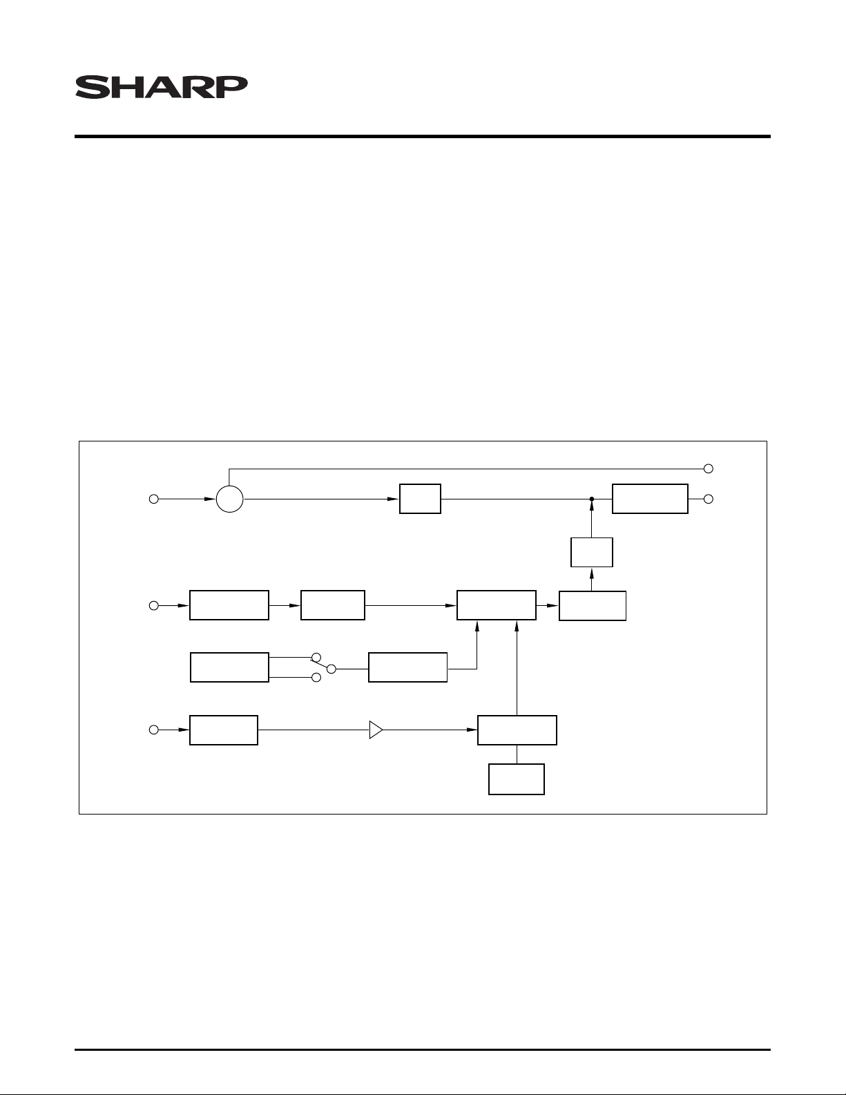
Figure 1. Block Dia gr a m
MODULATOR
FM
MODULATOR
TANK
(4.5 MHz)
RF SW
BANDPASS
FILTER
MOD20-3
RF Data Sheet 1

VT5F9MN0006/07 RF Modulator
SPECIFICATIONS
General Description
• U.S. standard transmission system
• NTCS color system
• Output channel 3, 4
• Output impedance 75 Ω, unbalanc ed
• Power source 5 (VDC) +B (MOD)
Test Condition
• Power source 5 ±0.1 (VDC) +B (MOD)
– Ripple 30 mVp-p MAX.
• Unit setting conditions
– Video: Apply 75% modulated color bar signal 1
Vp-p and set modulation factor and V/S ratio to
specified values. For modulation factor setting,
WHITE signal shall be 1 Vp-p V/S = 7/3,
APL = 50%.
– Audio: Add 1.24 Vp-p
• Ambient Conditions
– Temperature 25°C ±3
– Humidity 65% ±5 RH
– If judgment is not in doubt, standard tem pera-
ture may be considered as 15° to 30°C and humidity 45% to 85% RH.
Electrical Performance (RF MOD Portion)
• Video Characteristics
– Input impedance 1 kΩ ±30%, unbalanced
– Measure at 0 to 4.2 MHz
– Input signal level 1 Vp-p synchronous (–)
– When load of 82 Ω is applied
– Modulation factor 77 ±7%
– When load of 82 Ω is applied
– V/S Ratio
– 7 +0.25, -0. Input: Staircase wave 1 Vp-p syn-
chronous (–)
– 3 +0, -0.25. V/S = 7/3
– Amplitude frequency characteristics +2 dB, -3
(MAX.)
– Using 1 MHz as a standard in the 0 to 4.2 MHz
range, measure at RF output using multibu rst
or sweep generator. Spectrum analyze r band
is 300 kHz.
– Differential gain 10% (MAX.)
– Superimposed 3.58 MHz sine wave level shall
be 20% of sta irc as e w av e lev el, m eas ur ed in a
modulation factor range of 65% to 75% and an
APL ran ge o f 10 % to 90%. Ho weve r, d i ffe rent i al
gain of demo dulator unit shall req uire correc tion.
– Differential phase 10° (MAX.)
– Superimposed 3.58 MHz sine wave level shall
be 20% of staircase wave level, measured in a
modulation factor range of 65% to 75% and an
APL rang e o f 10 % to 90%. Howev e r, d if fer enti al
gain of demo dulator un it shall requ ire corr ection.
– Change in modulation factor to APL ±5% (MAX.)
– Within an APL range of 10% to 90% with APL
50% as referenced.
– S/N ratio 45 dB (p-p/rms MIN.)
– Measure with standard demodulator output.
• Audio system characteristics
– Input impedance 30 kΩ, unbalanced (MIN.)
– Measure at 0.1 to 10 kHz
– Input signal level 1.24 Vp-p
– Amplitude frequency characteristics +2 dB, -3 dB
– Using 1 kHz as a standard in the 100 Hz to
10 kHz range, measure deviation between reference.
– Modulation factor 90 ±20%
– 100% = ±25 kHz (±25 kHz ±5 kHz)
– Distortion rate 3% (MAX.)
– S/N ratio 45 dB (MIN.), includes buzz
• Output system characteristics.
– Video carrier frequency ±100 kHz (MAX.)
– For test conditions, temperature shall be 25°C,
and humidity 65% RH.
– Audio frequency 4,500 kHz ±7 (MAX.)
– For test conditions, temperature shall be 25°C,
and humidity 65% RH.
– Video output level 66 dBµ ±3 (MAX.)
– p-p level (AT modulation): 75 Ω load
– Audio output level difference (P/S ratio) 16 dB +4,
-3 (MAX.)
– Difference between video output lev el and au-
dio output level (audio non-modulation)
– Output terminal spurious
– Specific frequency 16 dB +4, -3 (MAX.)
fp–4.5MHz
– Other frequencies 30 dB (MIN.). Measure as
per FCC regulations: 0 to 1,000 MHz, excluding frequency in preceding remark.
– Spurious radiation within the band 60 dB (MIN.)
– Between fp and fs
– Chroma beat (920 kHz) 50 dB (MIN.)
– Apply 3.58 MHz 0.3 Vp-p sine wave to video in-
put and measure using spectrum analyzer.
– Output VSWR 3 (MAX.)
– Worst point in the band at 75 Ω termination.
2 RF Data Sheet
 Loading...