

Page 1

SERVICE MANUAL
37VT-26H(GY)
SERVICE MANUAL
S99P337VT26H/
TV/VCR COMBINATION
TELEVIDEO
Chassis No. VP-8
37VT-26H(GY)
TV/VCR COMBINATION TELEVIDEO
Ë AIS (Automatic Instruction System)
Ë ASS (Automatic Sorting System)
Ë VPS/PDC (Video Program System / Program Delivery
Control)
Ë FASTEXT
Ë VIDEO Plus+
Ë Post Cord Security
Ë On Screen Digital Channel/Sound Level/Tuning Display,
Control (Contrast, Colour, Brightness, Tint, Sharpness,
White temp) Symbol and Level
Ë Blue Back Off Timer
Ë 52 Key, Wireless Remote Control Unit
MODEL 37VT-26H(GY)
» SPECIFICATIONS ................................................................................................................................................................................. 2
» IMPORTANT SERVICE NOTES............................................................................................................................................................ 3
» LOCATION OF USER'S CONTROL ...................................................................................................................................................... 4
» DISASSEMBLY AND REASSEMBLY .................................................................................................................................................... 6
» ADJUSTMENT OF THE TV ELECTRICAL CIRCUITRY ........................................................................................................................9
» PRECAUTIONS IN REASSEMBLING ................................................................................................................................................ 19
» FUNCTION OF MAJOR MECHANICAL PARTS ................................................................................................................................. 20
» ADJUSTMENT, REPLACEMENT AND ASSEMBLY OF MECHANICAL UNITS ................................................................................. 22
» ADJUSTMENT OF THE VCR ELECTRICAL CIRCUITRY ...................................................................................................................41
» MECHANISM OPERATION FLOWCHART AND TROUBLESHOOTING GUIDE ...............................................................................44
» CHASSIS LAYOUT .............................................................................................................................................................................. 63
» BLOCK DIAGRAM OF TV SECTION.................................................................................................................................................. 64
» BLOCK DIAGRAM OF VCR SECTION............................................................................................................................................... 66
» DESCRIPTION OF SCHEMATIC DIAGRAM ...................................................................................................................................... 75
» SOLID STATE DEVICE BASE DIAGRAM ........................................................................................................................................... 76
» WAVEFORMS .....................................................................................................................................................................................77
» SCHEMATIC DIAGRAM ...................................................................................................................................................................... 78
» PRINTED WIRING BOARD ASSEMBLIES......................................................................................................................................... 92
» REPLACEMENT PARTS LIST ............................................................................................................................................................ 99
» PACKING OF THE SET..................................................................................................................................................................... 115
MODEL
In the interests of user-safety (Required by safety regulations in some countries) the set should be restored to its
original condition and only parts identical to those specified
be used.
FEATURE
Ë Channel Skip
Ë High Speed and Double Speed Video Search System
Ë DPSS (Digital Program Search System)
Ë Quick Start Playback with Full Loading System
Ë Digital Automatic Tracking Control
Ë Automatic Playback Function
Ë AHC (Automatic Head Cleaning System)
Ë Sharp Super Picture
Ë 345 Times Hi-Speed FF/REW
CONTENTS
37VT-26H(GY)
» PAL : 3 times/7 times (SP/LP)
» NTSC : 3 times/5 times (SP/LP)
5 times/15 times (EP)
Page
WARNING
The chassis in this receiver is partially hot. Use an isolation transformer between the line cord plug and power
receptacle, when servicing this chassis. To prevent electric shock, do not remove cover. No user – serviceable
parts inside. Refer servicing to qualified service personnel.
SHARP CORPORATION
1
Page 2

37VT-26H(GY)
Ë
OUTLINE OF THE PRODUCT
Receiving Broadcast Standard: I
Antenna Input Impedance: VHF/UHF;75 ohm Unbalanced (DIN)
Ë
TV SECTION
SPECIFICATIONS
Power Source: 220~240 V AC, 50 Hz
Power Consumption: 77 W
Receiving Channel: VHF; 1A~S36
UHF; S37~C57
Receiving System: Sound; 6.0 MHz
Colour; PAL
Video Signal: Input; 0.5-2.0 Vp-p/75 ohm (SCART/RCA)
Output; 1.0 Vp-p/75 ohm (SCART)
Audio Signal: Input; 0.5 Vrms/10k ohm (SCART/RCA)
Output; 0.5 Vrms/1k ohm (SCART) (54% MOD)
Temperature: Operation; 5°C to 40°C
Storage; -10°C to 60°C
Dimensions (Approx.): 378 mm (W) × 387 mm (H) × 384 mm (D)
Weight (Approx.): 12.7 kg
Cabinet Material: Plastic
Accessories: Operation Manual
Infrared Remote Control Unit
Dry Batteries, Type AA (×2 pcs.)
Viewing Area: 33.54 cm Diagonal Measurement
Picture Power: 22.0 kV at 800 µA Beam Current
Speaker Output: 3.0 W at Max. (5×9 cm oval type ×1pc.)
Picture Tube: T ype; VB370BVBK1S-S (Tint T ube)
Heater; 6.3 V, 300 mA
Focus; High Bi-Potential Electrostatic
Ë
VCR SECTION
Outline: VHS Video System Colour Video Cassette Recorder
Format: VHS PAL/NTSC Standard
Video Recording System: Rotary Slant Azimuth 2-Head Helical Scan System
Luminance: FM Recording
Chrominance: Low Frequency Converted Direct Recording
Video Signal System: PAL/NTSC 3.58MHz Colour
Cassette Tape: VHS T ype Video Cassette T ape
Tape Width: 12.7 mm
Tape Speed: PAL ; 23.39 mm/s (SP), 11.70 mm/s (LP)
NTSC ; 33.35 mm/s (SP), 16.68 mm/s (LP·PB only), 11.12 mm/s (EP)
Recording/Playback Time: SP ; Max. 240 min (with E-240)
LP ; Max. 480 min (with E-240, PAL only)
EP ; Max. 480 min (with T-160, NTSC only)
Number of Video Head: 4 pcs.
Note: The antenna must correspond to the new standard DIN 45325 (IEC 169-2) for combined UHF antenna with
75 ohm connector.
Specifications are subject to change without prior notice.
2
Page 3

IMPORTANT SERVICE NOTES
Maintenance and repair of this receiver should be done by qualified service
personnel only.
SERVICING OF HIGH VOLTAGE SYSTEM AND PICTURE TUBE
When servicing the high voltage system, remove static charge fr om it by connecting a 10k ohm Resistor in series with an insulated wire (such as a test
probe) between picture tube dag and 2nd anode lead. (A C line cord should be
disconnected from AC outlet.)
1. Picture tube in this receiver employs integral implosion protection.
2. Replace with tube of the same type number for continued safety.
3. Do not lift picture tube by the neck.
4. Handle the picture tube only when wearing shatterproof goggles and after discharging
the high voltage completely.
37VT-26H(GY)
X-RAY
This receiver is designed so that any X-Ray radiation is kept to an absolute
minimum. Since cer tain malfunctions or servicing may produce potentially
hazardous radiation with prolonged exposure at close range, the following
precautions should be observed:
1. When repairing the circuit, be sure not to increase the high voltage to more than 25.3 kV,
(at beam 0 µA) for the set.
2. T o keep the set in a normal operation, be sure to make it function on 22.0 kV + 1.5 kV – 2.0
kV (at beam 800 µA) in the case of the set. The set has been factory – Adjusted to the
above-mentioned high voltage.
∴ If there is a possibility that the high voltage fluctuates as a result of the repair s, never
forget to check for such high voltage after the work.
3. Do not substitute a picture tube with unauthorized types and/or brands which may cause
excess X-ray radiation.
BEFORE RETURNING THE RECEIVER
Before returning the receiver to the user , perform the following saf ety checks.
1. Inspect all lead dress to make certain that leads are not pinched or that hardware is not
lodged between the chassis and other metal parts in the receiver.
2. Inspect all protective devices such as non-metallic control knobs, insulating fishpapers,
cabinet backs, adjustment and compartment covers or shields, isolation resistor-capacity networks, mechanical insulators etc.
3
Page 4

37VT-26H(GY)
LOCATION OF USER'S CONTROL
4
Page 5
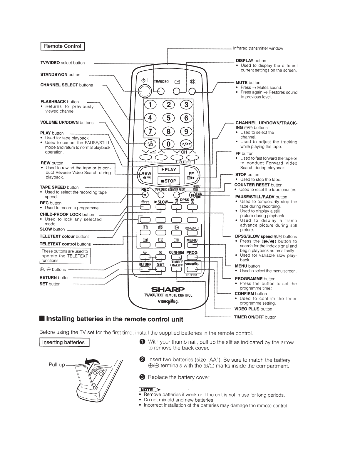
LOCATION OF USER'S CONTROL (CONTINUED)
37VT-26H(GY)
5
Page 6

37VT-26H(GY)
DISASSEMBLY AND REASSEMBLY
1. Remove the 11 rear cover fixing screws and detach the rear cover.
2. Take out the anode cap, CRT PWB, connectors H, G and F, coating ground, SP chip, fixing screws and others.
3. Remove the Main PWB fixing screws and take out the Main PWB unit and the Power PWB.
4. Remove the 4 Power PWB fixing screws, and take out the Power PWB unit.
1
1
2
H
G
F
4
3
6
Page 7

37VT-26H(GY)
DISASSEMBLY AND REASSEMBLY (CONTINUED)
5. Remove the 8 VCR fixing screws, and detach the shielding case.
6. Remove the 4 cassette housing control fixing screws, and detach the cassette housing control.
7. Remove the 7 mechanism chassis fixing screws, and detach the mechanism chassis from the Main PWB.
8. Remove the 3 Main PWB fixing screws, and detach the Main PWB.
9. Remove the 2 Tuner/Def and IF PWB fixing screws, and detach the Tuner/Def and IF PWB.
5
6
7
7
7
7
8
9
7
Page 8

37VT-26H(GY)
DISASSEMBLY AND REASSEMBLY (CONTINUED)
For servicing any of the components inside, disconnect the lead dressing holder . Position the main PWB unit upright
as shown below and connect the leads for starting the services.
AB
G
PC
PA
K
H
A
PB
AV
H
A
F
PB
AO
F
G
S
AB
Note: Fit the VCR unit the front cabinet with the front flap door tilted at 70~80°.
K
PA
S
AV
AJ
PC
AJ
70~80°
8
Page 9
ADJUSTMENT OF THE TV ELECTRICAL CIRCUITRY
ADJUSTMENT PRECAUTIONS
1. Calling the service mode
Get the service test points (TP2002 and TP2003) of the set short-circuited.
2. Getting out of the service mode
Get the above service test points open.
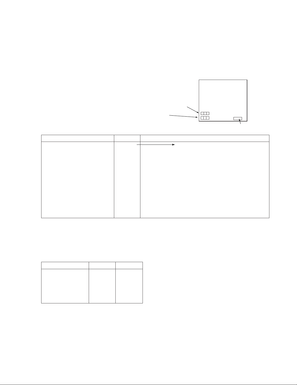
3. On-screen display in the service mode
A service mode item and its data appear in two lines
at the lower left on the screen.
Top line : Service mode item (See below)
Bottom line : Data (See below)
37VT-26H(GY)
Service mode
Item Display Data Variable range
DIRECT MODE → Adjustable in the DIRECT MODE
V-AMPLITUDE V-AMP 0 ~ 127 R CUT OFF (0 ~ 255)
V-LINEARITY V-LIN 0 ~ 31 G CUT OFF (0 ~ 255)
V-OUT PHASE V-POS 0 ~ 7 B CUT OFF (0 ~ 255)
H-POSITION H-POS 0 ~ 31 G DRIVE GAIN (0 ~ 255)
BELL FILTER BELL 0 ~ 3 B DRIVE GAIN (0 ~ 255)
R-Y BLACK OFFSET R-Y 0 ~ 15
B-Y BLACK OFFSET B-Y 0 ~ 15
Y-SUB CONTRAST CONT 0 ~ 31
SUB COLOUR COLOR 0 ~ 240
SUB BRIGHT BRI 0 ~ 150
SUB TINT TINT 0 ~ 37
Note :
Item selectable by the CH '" keys and data by the VOL '" keys (effective on both the
remote controller and the set)
The numeric keys on the remote controller work as follows in the DIRECT mode only.
UP DOWN
R CUT OFF 1 4
G CUT OFF 2 5
B CUT OFF 3 6
G DRIVE GAIN 7
B DRIVE GAIN 8 0
Õ
õ
Micon version display
Notes :
In all the other modes, these keys are used to select channels.
In the DIRECT TUNING mode, these keys are used to enter data.
9
Page 10

37VT-26H(GY)
Item-by-item control in the service mode
1. DIRECT mode F-B/W 0 - > 1 (forced B/W)
2. DIRECT mode + HOR. POS. mode DRV CNT 0 - > 1 (drive forced center)
3. R-Y Black Offset CONTRAST MAX (USER-CONTROL)
4. B-Y Black Offset CONTRAST MAX (USER-CONTROL)
5. SUB Tint MUTE MODE Y -MUTE
6. Unspecified items PICTURE NORMAL (CONT. BRI. COL.)
SUB-BRIGHT Initial value
R.G.B. CUTOFF 0 (E2PROM data resumed when any of the “0” thru
“9” keys on the remote controller is pressed)
BRIGHT MAX (USER-CONTROL)
COLOUR CENTER (USER-CONTROL)
R-MONITOR SW 0 - > 1 (MONITOR OUT)
MUTE MODE Y-MUTE
BRIGHT MAX (USER-CONTROL)
COLOUR CENTER (USER-CONTROL)
B-MONITOR SW 0 - > 1 (MONITOR OUT)
MUTE MODE Y-MUTE
Note :
All the settings will be back to the initial ones when shifting into any other mode or getting out of the
service mode.
Allocation of special keys in the service mode
`HORIZONTAL POSITION key CONFIRM (SET -> S-PICTURE)
`Y-MUTE KEY SET
`COLOUR MAX./MIN. select key TIMER ON/OFF
`DIRECT TUNING MODE KEY RETURN
`VCR SLOW TEST KEY PROG
`NVM MODE KEY DISPLAY
Adjustment precautions
1) Basically follow the sequential order of adjustments.
(Unless otherwise specified, follow the adjustment procedures.)
2) The “`”-marked steps in the adjustment procedures are automatically taken when in the service mode. Leave
out these steps.
3) For adjustments in the service mode, it is necessary to have the remote controller at hand.
Trouble indicators
If the set is interrupted by the protectors, the following indicators work to identify a spot in trouble.
1) LED (red) flashing : Deflection system protector activated (high-voltage or beam vert, out protector)
2) REC LED flashing : IIC bus line error (VCJ or tuner, EEPROM, TEXT, PDC)
3) LED off : Power protector activated (+B line short-circuited)
10
Page 11

Initial settings of EEPROM data
Initial settings of adjustment items
Item V ariable range Initial setting
R CUT OFF 0 ~ 255 0
G CUT OFF 0 ~ 255 0
B CUT OFF 0 ~ 255 0
V-AMPLITUDE 50Hz 0 ~ 127 35
V-AMPLITUDE 60Hz 0 ~ 127 37
V-LINEARITY 50Hz 0 ~ 31 25
V-LINEARITY 60Hz 0 ~ 31 18
V-OUT PHASE 50Hz 0 ~ 7 05
V-OUT PHASE 60Hz 0 ~ 7 02
HORIZONTAL POSITION 50Hz 0 ~ 31 05
HORIZONTAL POSITION 60HZ 0 ~ 31 09
Y-SUB CONTRAST 0 ~ 31 0
SUB-COLOUR 0 ~ 240 91
SUB-BRIGHT 0 ~ 150 100
G-DRIVE GAIN 0 ~ 255 128
B-DRIVE GAIN 0 ~ 255 128
SUB-TINT 0 ~ 37 20
BELL FO 0 ~ 3 01
R-Y BLACK OFFSET 0 ~ 15 8
B-Y BLACK OFFSET 0 ~ 15 8
37VT-26H(GY)
PICTURE Adjust User setting
Initial setting : NORMAL (CONTRAST at 52, others at CENTER)
11
Page 12

37VT-26H(GY)
ab
A=B
AB
A=B
AB
ËË
Ë
ËË
PURITY ADJUSTMENT
1. PURITY ADJUSTMENT
1. First of all, let a beam current of over 400µA flow
in the set to warm it up for 30 minutes or longer.
2. Keep the purity magnet in the zero magnetic field
in advance. Roughly adjust the static convergence.
3. Receive the green-only colour signal. Adjust the
beam current to about 500 µA.
4. Degauss the cathode ray tube enough with the
degaussing coil.
ADJUSTMENT
Eastward magnetic field specified
1) Observe the beam landings “a” and “b”, as
shown in
just the landings as specified. (
2) If the right and left landings are equally out-
ward, move the deflection yoke forward.
3) If the right or left landing is shifted to the right
or to the left, adjust the opening angle of the
purity magnet.
4) Make sure the right and left beam landings are
just as specified about the screen center. Now
check the cathode ray tube corners.
Be sure that all the landings are at rank “B”.
5) If any other colour appears on the screen,
move the deflection yoke back and forth.
LANDING ERROR
» Outward: Mov e the deflection yoke forward.
» Inward: Move the deflection y oke bac kward.
6) Receive the monoscope pattern signal.
RASTER ROTATION
7) Adjust the raster rotation to “0” eastward.
» Adjustment error : 0 ±2 mm
8) Tighten up the deflection coil screws.
» Tightening torque : 11±2 kg
Note : Each time the single-colour key is pressed,
the screen colour changes as follows.
Fig. A
, through a microscope. Ad-
Fig. B, Fig. C
Fig. A
)
Fig. B
Fig. C
Green-only
screen
Red-only
screen
Single-colour
screen cleared
Blue-only
screen
12
Page 13

ËË
Wedge "a"
Lacqure
Wedge "b" Wedge "c"
Approx.100° Approx.100°
B G R
B
G
R
R G B
B
G
R
R G B
R
G
B
B G R
R
G
B
Ë
ËË
CONVERGENCE ADJUSTMENT
1. CONVERGENCE ADJUSTMENT
(to be done after the purity adjustment)
1. Receive the crosshatch pattern signal.
2. Using the remote controller, call the Normal mode.
STATIC CONVERGENCE
1. Turn the 4-pole magnet to a proper opening an-
gle in order to superimpose the blue and red colours.
2. Turn the 6-pole magnet to a proper opening an-
gle in order to superimpose the green colour over
the blue and red colours.
DYNAMIC CONVERGENCE
1. Adjust the convergence on the fringes of the
screen in the following steps.
» Fig. a : Drive the wedge at point “a” and
swing the deflection coil upward.
» Fig. b :Drive the wedges at points “b” and
“c” and swing the deflection coil
downward.
» Fig. c : Drive the “c” wedge deeper and
swing the deflection coil rightward.
» Fig. d :Drive the “d” wedge deeper and
swing the deflection coil leftward.
2. Fix all the wedges on the cathode ray tube and
apply glass tape over them.
3. Apply lacquer to the deflection yoke lock screw,
magnet unit (purity, 4-pole and 6-pole magnets),
and magnet unit lock screw.
Fig. a
Fig. c
37VT-26H(GY)
Fig. b
Fig. d
Finally receive the red-only and blue-only colour signals and make sure there is no other colour mixed
on the screen.
4-pole magnet
6-pole magnet
Purity magnet
Fig. 1
CRT neck
Lacquer
13
Page 14

37VT-26H(GY)
ËË
Ë CRT CUT-OFF, BACKGROUND AND SUB-CONTRAST ADJUSTMENT (1)
ËË
1. CRT CUT-OFF (I2C bus data adjustment)
1. Receive the monoscope pattern signal.
2. Put the set in the service mode and call up the DIRECT mode (DIRCT).
3. Set the screen control to 0/10 position.
4. Press the “CONFIRM” key on the remote controller to reach the horizontal centering mode. (S-PICTURE k ey on
the set)
5. Turn the screen control clockwise until the horizontal raster of the first glimmering colour becomes slightly
visible.
6. Adjust the cut-off data of the other two colours until the horizontal raster becomes whitish.
Note : The data can be turned up and down with the above keys.
» R CUT OFF UP “1” KEY » G CUT OFF DOWN “5” KEY
» R CUT OFF DOWN “4” KEY » B CUT OFF UP “3” KEY
» G CUT OFF UP “2” KEY » B CUT OFF DOWN “6” KEY
7. Turn the screen control counterclockwise until the horizontal raster disappears.
Note : Before starting this adjustment, warm up the unit for 30 min utes or longer at a beam current of over
600 µA.
8. Press the “CONFIRM” k e y on the remote controller to call up the NORMAL mode . (S-PICTURE key on the set)
SUB-BRIGHTNESS (I2C bus data adjustment)
9. Using the remote controller, call the SUB-BRIGHT setting mode (BRI). (Receive the crosshatch and gray scale
signal.)
10.Set the sub-brightness data so that the third black portion (1st to 5th counted from the left of the screen) of the
window pattern looks sinking.
Note : The service mode adjustment in the above steps 9. and 10. should be carried out after the white
balance and background adjustments.
11.Exit from the service mode.
2. WHITE BALANCE AND BACKGROUND (I2C bus data adjustment)
1. Receive the monoscope pattern signal.
2. Put the set in the service mode and call up the DIRECT mode (DIRCT).
3. Connect the beam ammeter between TP601 and TP602.
4. Using the sub-contrast control, roughly adjust the beam current to about 700 µA.
5. Adjust the G-drive and B-drive data to have a colour temperature of 9,000°K (white).
» 9,000°K x : 0.290
y : 0.284
(with a Minolta colour temperature meter CA-100)
Note : The data can be turned up and down with the above keys.
» G-DRIVE UP “7” KEY » B-DRIVE UP “8” KEY
» G-DRIVE DOWN “
6. Adjust the contrast and brightness controls to have the beam current of 200 µA or so. Now check the back-
ground colour. If the colour temperature is not as specified, go back to No. 1 on the preceding page.
7. Exit from the service mode.
Note : Before starting this adjustment, warm up the unit for 30 min utes or longer at a beam current of over
600 µA.
Õ
” KEY » B-DRIVE DOWN “0” KEY
õ
14
Page 15

ËË
Ë
ËË
CRT CUT-OFF, BACKGROUND AND SUB-CONTRAST ADJUSTMENT (2)
3. SUB-CONTRAST
(I2C bus data adjustment)
1. Receive the crosshatch pattern signal.
2. Put the set in the service mode and select the SUB-CONTRAST mode (CONT).
3. Adjust the sub-contrast data to "0".
4. Exit from the service mode.
ËË
Ë
ËË
HORIZONTAL AND VERTICAL CIRCUIT ADJUSTMENT
1. SERVICE MODE DATA ADJUSTMENT
Put the set in the service mode.
Turn up or down the data for this adjustment.
I2C bus data adjustment
» V-AMP 50 Hz
A) Select the V-AMP mode (V-AMP). Adjust the
overscan to 9% .
» V-LINEARITY - 50 Hz
B) Select the V-LIN mode (V-LIN). Adjust to get the
best linearity.
» V-OUT PHASE - 50 Hz (V-CENTER)
C) Select the V-OUT POS mode (V-POS). Align the
screen center with the cathode ray tube’s geometrical center.
» H-POS 50 Hz (H-CENTER)
D) Select the H-POS mode (H-POS). Make the dis-
tances “A” and “B” on both sides equal.
Exit from the service mode.
Note :
The selected channels in parentheses have the
following signals.
Monoscope pattern (50 Hz) signal
A
Fig.2
B
37VT-26H(GY)
For the V-AMP 60 Hz, V-LINEARITY 60 Hz, V-OUT PHASE 60 Hz, and H-POS 60 Hz adjustments, their corrected
data are automatically entered when the corresponding 50-Hz mode adjustments are made. Chec k these data on
the 60 Hz mode screen. Readjust any of them if required. (The 50 Hz and 60 Hz modes are selected on the
screen.)
Once the adjustment has been made in the 60 Hz mode, do not change it in the 50 Hz mode.
2. FOCUS ADJUSTMENT
1. Receive the monoscope pattern signal.
2. Make the PICTURE ADJUST setting to NORMAL.
3. Adjust the focus control so that the middle areas
between the pattern’s center and the screen’ s both
ends be in the best focus.
Adjust point
Fig.3
15
Page 16

37VT-26H(GY)
W
YCYG
MG
R
B
To be at the same level
ËË
Ë
ËË
PAL CHROMA ADJUSTMENT
1. SUB-COLOUR ADJUSTMENT (I2C bus data adjustment)
1. Receive the PAL colour bar signal.
2. Put the set in the service mode.
3. Select the sub-colour mode (COL).
4. Connect the oscilloscope to TP1852 (RED cath-
ode). (Use a 10 : 1 probe.)
» Range: 20 V/div .
» Sweep time: 20 µsec/div.
5. Adjust the sub-colour data so that the 75% white
and red portions of the PAL colour bar be at the
same level. See
6. Exit from the service mode.
» When getting out of the SUB-COLOUR mode,
the sub-colour data turns up 15.
ËË
Ë
ËË
NTSC CHROMA ADJUSTMENT
Fig. 4
.
1. SUB-TINT ADJUSTMENT (I2C bus data adjustment)
1. Receive the NTSC colour bar signal.
2. Put the set in the service mode.
3. Select the SUB-TINT mode (TINT).
4. Connect the oscilloscope to TP802 (B-Y OUT).
» Range : 10 mV/div. (AC)
» Sweep time :10 µsec/div.
(Use a 10 : 1 probe.)
5. Adjust the sub-tint data to obtain the wavef orm as
shown in
6. Exit from the service mode.
Fig. 5
.
Fig.4
CY
GMGR
Y
W
B
About 3 Vp-p
Fig.5
ËË
Ë
ËË
A/V INPUT AND OUTPUT CHECK (1)
1. VIDEO and AUDIO OUTPUT CHECK
1. Receive the E-69CH.
(100% white colour bar, 400 Hz, 100% modulation audio)
2. Terminate the video output with a 75Ω impedance. Make sure the out-
put is as specified
(1.0 Vp-p ± 3 dB(0.71 – 1.41 Vp-p).
3. Terminate the audio output with a 10k ohm impedance. Mak e sure the
output is as specified (2.6 Vp-p ± 3 dB(1.84 – 3.67 Vp-p).
» Make sure the video and audio signals from the tuner are outputted.
2. VIDEO and AUDIO INPUT CHECK
1. Receive the E-69CH.
2. Feed the video and audio signal via the A/V input jacks.
3. Using the CH '/" keys on the remote controller, change to the AV
mode and make sure the external video and audio outputs are accordingly given.
(The AV mode can be picked up between 1CH and 0CH.)
CH ' 99 → 0 → AV1 → AV2 → 1 → 2
CH " 2 → 1 → AV2 → AV1 → 0 → 99
» The AV mode may also be picked up using the TV/VIDEO key on
the remote controller.
RF → AV1 → AV2 → RF
WAVEFORM & OTHER
21PIN SCART
VIDEO OUT 19 PIN
AUDIO OUT 1, 3 PIN
SC401(REAR)........AV1
WAVEFORM & OTHER
SC401(REAR)........AV1
J1401(FRONT).......AV2
16
Page 17

ËË
Ë
ËË
A/V INPUT AND OUTPUT CHECK (2)
21PIN Euro-SCART (REAR)
37VT-26H(GY)
2468101214161820
121 35791113151719
1. Audio right output
2. Audio right input
3. Audio left output
4. Commom earth for audio
5. Earth for blue
6. Audio left input
7. Blue input
8. Audio-video control
9. Earth for green
10. Not used
11. Green input
12. Not used
13. Earth for red
14. Not used
15. Red input
16. Red/Green/Blue control
17. Earth for video
18. Earth for Red/Green/Blue control
19. Video output
20. Video input
21. Plug shield
Fig.6
ËË
Ë
ËË
PROTECTOR PERFORMANCE CHECK
1. BEAM PROTECTOR
1. Receive the monoscope pattern signal.
2. Set the contrast control to maximum.
3. Set the brightness control to maximum.
4. Make a short-circuit between the collector and emitter of Q1801 and
make sure that the protector is activated and the stand-by mode is
called. (The POWER LED indicator starts flashing in red.)
2. HIGH-VOLTAGE PROTECTOR
1. Receive the monoscope pattern signal.
2. Connect the bias box to TP603.
3. Adjust the bias box voltage to 20 V and mak e sure that the protector is
not activated.
Note : Normally about 19 V
4. Adjust the bias box voltage to 25 V and mak e sure that the protector is
activated.
3. OTHER PROTECTORS
» In checking the performance of other protectors — for example, the
one against shorting of smoothing electrolytic capacitor of +B line —,
pay attention not to damage or deteriorate any related element.
ËË
Ë
ËË
FUNCTION CHECK (1) (VIDEO AND AUDIO)
1. CONTRAST KEY
1. Receive the mono scope pattern signal.
2. Using the PICTURE ADJUST control, select CON-
TRAST .
3. The contrast must be changeable with the +/- ke y .
R/C
2. COLOUR KEY
1. Receive the PAL colour bar signal.
2. Using the PICTURE ADJUST control, select COL-
OUR.
3. The colour must be changeable with the +/- key.
(There must be no colour at the MIN position.)
3. BRIGHTNESS KEY
1. Receive the monoscope pattern signal.
2. Using the PICTURE ADJUST control, select
BRIGHT.
3. The black level must be changeable with the +/-
key.
MENU KEY
→PICTURE ADJUST
→CONTRAST
→COLOUR
→BRIGHT
→TINT
→V-TONE
→WHITE TEMP
→NORMAL
17
Page 18

37VT-26H(GY)
ËË
Ë
ËË
FUNCTION CHECK (2) (VIDEO AND AUDIO)
4. TINT KEY
1. Receive the NTSC colour bar signal. (AV2 input)
2. Using the PICTURE ADJUST control, select TINT.
3. The tint must be changeable toward green with the + key and toward red with the - key.
5. PIC-NORMAL KEY
1. With the PICTURE ADJUST control, select NORMAL. Make sure the following normal settings are displayed.
Here are the normal settings.
» Contrast : 52
» Colour : CENTER (0)
» Brightness : CENTER (0)
» Tint : CENTER (0)
» Sharpness : CENTER (0)
» White T emp : CENTER (0)
6. WHITE TEMP KEY
1. Receive the monoscope pattern signal.
2. Using the PICTURE ADJUST control, select WHITE TEMP.
3. The BACK GND must be changeable with the +/- k ey with the + k ey (The w arm direction with the + key, the cold
direction with the - key ).
7. V-TONE KEY
1. Receive the monoscope pattern signal.
2. Using the PICTURE ADJUST control, select V-TONE.
3. The sharpness must be changeable with the +/- key.
8. CHANNEL SIGH DISPLAY COLOUR
1. The display colour of all the channel (0 ~ 99) signs must be green (AFT on).
9. COLOUR SYSTEM KEY
1. Input PAL COLOUR BAR with AV 1, 2. Using the
COLOUR SYSTEM key, select a mode other than
AUT O/P AL and mak e sure the colour system does
not work properly.
2. When receive the E-69CH. PAL COLOUR BAR,
make sure the colour system work properly.
3. When receive the JA-8CH NTSC 3.58 COLOUR
BAR, make sure the colour system does not work
properly .
R/C
MENU KEY
→COLOUR SYSTEM
(Selection is possible only at the time of the AV mode.)
18
Page 19

PRECAUTIONS IN REASSEMBLING
INSTALLING THE CASSETTE CONTROLLER
When the cassette controller is installed on the mechanism, the initial setting is essential condition.
There are two initial setting methods, namely electrical
and mechanical.
1. Electrical initial setting
Make a short-circuit between TP7701 and TP7702 then
plug in the AC cord and be sure that the mechanism is
back to its initial setting position (*1). Now install the
cassette controller in position. (Conditions: When mechanism and PWB have been installed)
Pulley feed gear
Screwdriver
37VT-26H(GY)
2. Mechanical initial setting
Feed the pulley feed gear of loading motor with screw
driver. After ascertaining the return to the initial set
position (*1) install the cassette controller in the specified position. (This method is applied only for the mechanism.)
Casecon
drive gear
Tilt mark (*1)
INSTALLING THE MECHANISM ON PWB
Lower vertically the mechanism, paying attention to the
mechanism edge, and install the mechanism with due
care so that the parts are not damaged. So as to fix the
mechanism to the main PWB tighten up the two screws.
(One for fixing the mechanism and the head amplifier
shield, the other on the main PWB's soldering side and
located near the loading motor.) Connect again the FFC
cable (AA-MH, AD-ME, AH-MZ) between the mechanism and the main PWB.
END SENSOR
REC TIP SW
Drive angle of
cassette control
PARTS WHICH NEED PARTICULAR CARE
When installing the mechanism chassis on the PWB
unit, take care so as to prevent deformation due to
contact of mechanism chassis with Rec tip switch
(S7701), Start sensor (Q7703) and End sensor (Q7704).
AE CONNECTOR
AC CONNECTOR
19
AL CONNECTOR
START SENSOR
Page 20

37VT-26H(GY)
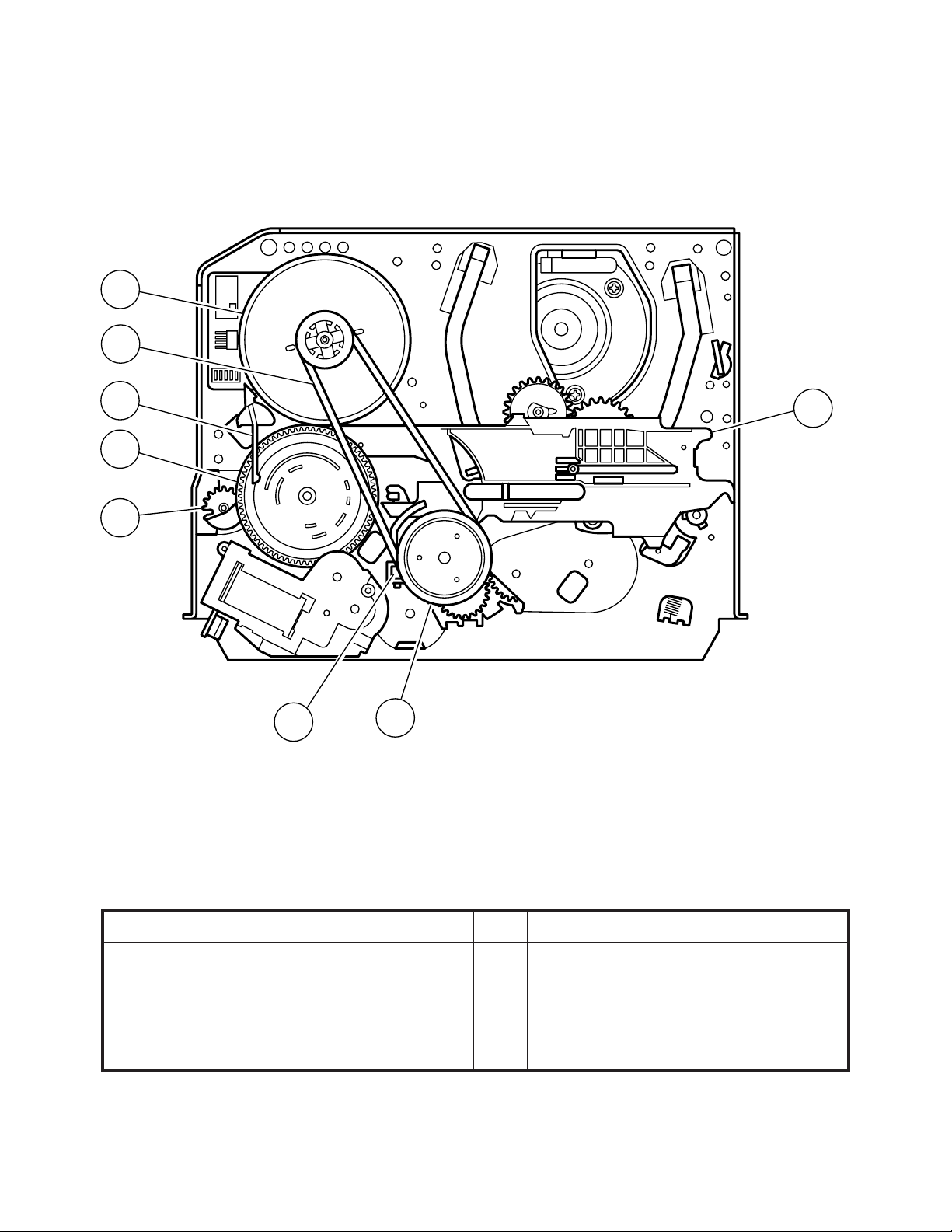
FUNCTION OF MAJOR MECHANICAL PARTS (TOP VIEW)
1715
18
10
27
14
1
9
2
7
3
11
5
12
8
No. Function
1 Full erase head
2 Supply pole base ass'y
3 Tension arm ass'y
4 Idler wheel ass’y
5 Pinch drive lever ass’y
6 Supply reel disk
7 Supply main brake ass'y
8 Take-up main brake ass'y
9 Pinch drive cam
10 A/C Head ass’y
16
6
4
No. Function
11 Reverse guide lever ass'y
12 Casecon drive gear
13 Take-up reel disk
14 Pinch roller lever ass’y
15 Drum ass'y
16 Loading motor
17 Drum motor
18 Take-up pole base ass'y
27 Fixing guide
13
20
Page 21
37VT-26H(GY)
FUNCTION OF MAJOR MECHANICAL PARTS (BOTTOM VIEW)
21
22
19
20
12
23
26
24
No. Function
19 Slow brake lever
20 Master cam
21 Capstan D.D. motor
22 Reel belt
No. Function
23 Clutch lever
24 Limiter pulley ass'y
(12) Casecon drive gear
26 Shifter
21
Page 22
37VT-26H(GY)
ADJUSTMENT, REPLACEMENT AND ASSEMBLY OF MECHANICAL UNITS
The explanation given below relates to the on-site general service (field service) but it does not relates to the adjustment
and replacement which need high-grade equipment, jigs and skill. For example, the drum assembling, replacement and
adjustment service must be performed by the person who have finished the technical courses.
Note :
There is a function to cut off the high voltage of TV by taking the plug of P2002 off the socket SC2002 in Main PWB
in order to check only VCR part including mechanism.
So you can use this function in the case of checking and adjusting mechanism.
1. MECHANISM CONFIRMATION ADJUSTMENT JIG
So as to perform completely the mechanism adjustment prepare the following special jigs. So as to maintain the initial
performance of the machine the maintenance and check are necessary. Utmost care must be taken so that the tape
is not damaged. If adjustment needs any jig, be sure to use the required jig.
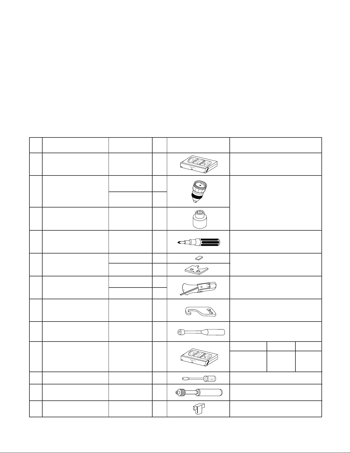
No. Jig ltem Part No. Code Configuration Remarks
1. Torque Cassette Meter JiGVHT-063 CZ
JiGTG0090 CM
2.
Torque Gauge
JiGTG1200 CN
3. Torque Gauge Head JiGTH0006 AW
4. Torque Driver JiGTD1200 CB
Master Plane Jig and
Reel Disk Height
5.
Adjusting Jig
JiGRH0002 BR
JiGMP0001 BY
JiGSG2000 BS
Tension Gauge6.
JiGSG0300 BF
Pinch pressing force
7. JiGADP003 BK
measuring jig
Reverse guide height
8.
adjustment box driver
JiGDRiVER11055
AR
This cassette torque meter is used for checking and adjusting the torque of take-up for
measuring tape back tension.
These Jigs are used for checking
and adjusting the torque of take-up
and supply reel disks.
When fixing any part to the threaded
hole using resin with screw, use the
jig. (Specified torque 5 kg)
These Jigs are used for checking
and adjusting the reel disk height.
There are two gauges used for the
tension measurements, 300 g and
2.0 kg.
This Jig is used with the tension
gauge. Rotary transformer clearance adjusting jig.
This Jig is used for height adjustment of the
reverse guide (for reverse guide height adjustment).
Alignment Tape9. VROCPSV CK
Guide roller height
10. JiGDRiVERH-4 AP
adjustment driver
X value adjustment
11. JiGDRiVER-6 BM
gear driver
Reverse Guide Height
12. JiGRVGH-F18 BU
Adjusting Jig
22
Video Audio Track
625 Monoscope
and
Color Bar
This screwdriver is used for adjusting the
guide roller height.
For X value adjustment
6kHz
and
1kHz
49µm
This Jig is used for height
adjustment of the reverse guide.
Page 23

2. MAINTENANCE CHECK ITEMS AND EXECUTION TIME
Perform the maintenance with the regular intervals as follows so as to maintain the quality of machine.
37VT-26H(GY)
Maintained
Parts
Guide roller ass’y
Sup guide shaft
Reverse guide
Slant pole on pole base
Full erase head
A/C head
Upper and lower drum ass’y
Capstan D.D. motor
Pinch roller
Reel belt
500
hrs.
1000
hrs.
1500
hrs.
2000
hrs.
Possible symptom
encountered
Lateral noises Head
occasionally blocked
Colour and beating
Small sound or sound
distortion
Poor S/N ratio, no colour
Poor flatness of the
envelope with alignment
tape
No tape running,
uneven colour
No tape running, tape
slack
No tape running, tape
slack, no fast forward/
rewind motion
Remarks
Abnormal rotation or significant
vibration requires replacement.
Clean tape contact part with the
specified cleaning liquid.
Clean tape contact area with the
specified cleaning liquid.
Clean rubber and rubber contact
area with the specified cleaning
liquid.
Tension band ass’y
Loading motor
Idler ass’y
Limiter pulley
Supply/take-up main brake levers
Screen swaying
Cassette not loaded or
unloaded
No tape running, tape
slack
Tape slack
Replace the roller of the cleaner
AHC (Automatic Head Cleaner)
when it wears down.
Just change the AHC roller
assembly for new one.
NOTE : Part replacement. : Cleaning : Apply grease
<Specified> Cleaning liquid Industrial ethyl alcohol
* This mechanism does not need electric adjustment with variable resistor. Check parts. If any deviation is found,
clean or replace parts.
Video head cleaning procedure
1. Apply one drop of cleaning liquid to the cleaning paper with the baby oiler.
2. Gently press the cleaning paper against the video head to fix your finger, and move the upper drum so that each head
is passed to and fro 5 times (do not move the cleaning paper).
3. Wipe with the dry cleaning paper.
Notes :
• Use the commercially available ethanol of Class 1 as
cleaning liquid.
• Since the video head may be damaged, do not move up
and down the cleaning paper.
Gently press the cleaning paper to
fix with your finger, and rotate the
upper drum to clean.
Move to and fro 5 times for each head.
(Do not move the cleaning paper.)
Rotate the upper drum
with one hand.
• Whenever the video head is cleaned, replace the cleaning paper.
• Do not apply this procedure for the parts other than the
video head.
Parts Code Description Code
ZPAPRA56-001E Cleaning Paper AW
ZOiLR-02-24TE Babe Oiler (Spoit) AH
23
Page 24

37VT-26H(GY)
3.REMOVING AND INSTALLING THE
CASSETTE HOUSING
• Removal
1. In the cassette eject mode, remove the cassette.
2. Unplug the power cord.
3. Remove in the following numerical order.
a) Remove two screws 1.
b) Slide and pull up the cassette housing control.
1
Notes:
1. When fitting the S/E sensor holder to the cassette
controller frame L/R, take care.
2. Misengagement of teeth of casecon drive gear and
drive angle gear causes malfunction. (The cassette
cannot be set, load and ejection are repeated).
3. In the case when you use the magnet screw driver,
never approach the magnet driver to the A/C head,
FE head, and drum.
4. When installing or removing, take care so that the
cassette housing control and tool do not contact the
guide pin or drum.
5. After installing the cassette housing control once
perform cassette loading operation.
4.TO RUN A TAPE WITHOUT THE CASSETTE
HOUSING CONTROL ASSEMBLY
1. Short-circuit TP7701 (J930) and TP7702 (J359).
2. Plug in the power cord.
3. Turn off the power switch.
(The pole bases move into U.L.position.)
4. Open the lid of a cassette tape by hand.
5. Hold the lid with two pieces of vinyl tape.
6. Set the cassette tape in the mechanism chassis.
7. Stabilize the cassette tape with a weight (500g) to
prevent floating.
8. Turn on the power switch.
9. Perform running test.
Figure 1-1.
• Reassembly
1. Before installing the cassette housing control, shortcircuit TP7701 (J930) and TP7702 (J359) provided at
the left of the main PWB, press the eject button. The
casecon drive gear turns and stops when the positioning mark appears. Engage two teeth of casecon
drive gear with the three teeth of casecon drive angle
gear, and set on the mechanism chassis as shown
below.
Casecon
drive gear
Casecon drive
angle gear
500g
Weight to prevent
float (500g)
Mechanism chassis
Figure 1-3.
Note:
The weight should not be more than 500g.
• To take out the cassette tape.
1. Turn off the power switch.
2. Take out the cassette tape.
Figure 1-2.
2. Install in the reverse order of removal.
24
Page 25

37VT-26H(GY)
5.REEL DISK REPLACEMENT AND HEIGHT
CHECK
• Removal
1. Remove the cassette housing control assembly.
2. Pull the tension band out of the tension arm ass'y.
3. Remove the Supply/Take-up main brake ass'y.
4. Open the hook at the top of the reel disk, and remove
the reel disk.
Note:
Take care so that the tension band ass'y and main brake
ass'y (especially soft brake) are not deformed.
Tension arm ass'y
Supply main brake ass'y
Tension band ass'y
Supply reel disk
Take-up main brake ass'y
Take-up reel disk
Notes:
1. When installing the reel disk, take due care so that
the tension band ass'y is not deformed and grease
does no adhere.
2. Do not damage the Supply main brake ass'y. Be
careful so that grease does not adhere to the brake
surface.
• Reassembly (Take-up reel disk)
1. Clean the reel disk shaft and apply grease (SC-141) to it.
2. Align the phase of the reel disk to that of the reel relay
gear and to install a new take-up reel disk onto the
shaft.
3. Check the reel disk height and reassemble the takeup main brake ass'y.
Notes:
1. Take care so that the Take-up main brake ass'y is not
damaged. Take care so that grease does not adhere
the brake surface.
2. After reassembly, check the video search rewind
back tension (see 10.), and check the brake torque
(see 14.).
• Height checking and adjustment
Notes:
1. Set the master plane with due care so that it does not
contact the drum.
2. When putting the master plane, shift the reverse
guide a little in the loading direction. Care must be
taken since excessive shift results in damage.
Figure 1-4.
Note:
When the tension band ass'y is pressed in the direction of the
arrow for removal, the catch is hard to be deformed.
Figure 1-5.
• Reassembly (Supply reel disk)
1. Clean the reel disk shaft and apply grease (SC-141) to it.
2. Match the phases of reel disk and reel relay gear, and
set the new reel disk.
3. After checking the reel disk height, wind the tension
band ass'y around the reel disk, and insert into the
hole of tension arm ass'y.
4. Assemble the Supply main brake ass'y.
Master plane
Reverse
guide
Supply reel disk
Cassette lock
release shaft
Take-up reel disk
Position
pin
Figure 1-6.
Note:
Check that the reel disk is lower than part A but higher
than part B. If the height is not correct, readjust the reel
disk height by changing the poly-slider washer under
the reel disk.
25
Page 26

37VT-26H(GY)
Note:
Whenever replacing the reel disk, perform the height
checking and adjustment.
Master plane
10 ± 0.2mm
Reel disk
Reel disk
Reel disk height
adjusting jig
Mechanism chassis
A
B
Figure 1-7.
6. CHECKING AND ADJUSTMENT OF TAKE-UP
TORQUE IN FAST FORWARD MODE
• Remove the cassette housing control assembly.
• After short-circuiting TP7701 (J930) and TP7702
(J359) provided at the left on the main PWB, plug
in the power cord, then turn on the power.
• Setting
1. Set a torque gauge to zero on the scale. Place it on
the take-up reel disk.
2. Press the FF button.
3. To calculate the remaining capacity of the play back
mode, slowly rotate the supply reel disk, and then
shift it into the forward mode.
Notes:
1. Hold the torque gauge by hand so that it is not moved.
2. Do not keep the reel disk in lock state. Do not allow
long-time measurement.
7. CHECKING AND ADJUSTMENT OF TAKE-
UP TORQUE IN REWIND MODE
• Remove the cassette housing control assembly.
• After short-circuiting TP7701 (J930) and TP7702
(J359) provided at the left on the main PWB, plug
in the power cord, then turn on the power.
• Setting
1. Set a torque gauge to zero on the scale. Place it on
the supply reel disk.
2. Press the rewind button.
3. To calculate the remaining capacity, slowly rotate the
take-up reel disk, and then shift it into the rewind
mode.
• Checking
1. Turn the torque gauge slowly (one rotation every 2 to
3 seconds) by hand in the CCW direction.
2. Make sure that the indication of torque gauge is not
less than 30mN·m (306gf·cm).
Torque gauge
• Checking
1. Turn the torque gauge slowly (one rotation every 2 to
3 seconds) by hand in the CW direction.
2. Make sure that the indication of torque gauge is not
less than 30mN·m (306gf·cm).
Torque gauge
30mN·m (306gf·cm)
or more
Idler ass'y
CW
The gauge is held at
its maximum value.
(Red mark)
Figure 1-8.
• Adjustment
1. If the FF winding-up torque is less than the specified
value, clean the capstan D.D. motor pulley, reel belt,
and limiter pulley with cleaning liquid, and check
again.
2. If the torque is less than the set value, replace the reel
belt.
30mN·m (306gf·cm)
or more
CCW
The gauge is held at
its maximum value.
(Red mark)
Supply reel disk
Idler ass'y
Figure 1-9.
• Adjustment
1. If the rewind winding-up torque is less than the
specified value, clean the capstan D.D. motor pulley,
drive belt, and limiter pulley with cleaning liquid,
rewind again, and check the winding-up torque.
2. If the winding-up torque is still out of range, replace
the drive belt.
Notes:
1. Hold the torque gauge by hand so that it is not moved.
2. Do not keep the reel disk in lock state. Do not allow
long-time measurement.
26
Page 27

37VT-26H(GY)
8.CHECKING AND ADJUSTMENT OF TAKEUP TORQUE IN RECORD/PLAYBACK MODE
• Remove the cassette housing control assembly.
• After short-circuiting TP7701 (J930) and TP7702
(J359) provided at the left on the main PWB, plug
in the power cord.
• Turn off the power switch.
• Open the cassette torque meter lid, and fix it with
tape.
• Load the cassette torque meter into the unit.
• Put the weight (500g) on the cassette torque
meter.
• Turn on the power switch.
• Press the REC button, and set LP picture record
mode.
Set value LP6.9 ± 2.5mN⋅m (70 ± 25gf⋅cm)
500g
9.CHECKING AND ADJUSTMENT OF TAKEUP TORQUE IN VIDEO SEARCH REWIND
MODE
• Remove the cassette housing control assembly.
• After short-circuiting TP7701 (J930) and TP7702
(J359) provided at the left on the main PWB, plug
in the power cord, then turn on the power.
• Setting
1. Press the playback button and rewind button to set
the video search rewinding mode.
• Checking
1. Place the torque gauge on the supply reel disk, and
turn it counterclockwise very slowly (one rotation
every 1 to 2 seconds) and check that the torque is
within the set value 14.0 ± 3.9mN⋅m. (144 ± 40gf⋅cm)
Torque gauge
CCW
Cassette torque meter
Figure 1-10.
• Checking
1. Make sure that value is within the setting 6.9±2.5mN·m
(70±25gf·cm).
2. The winding-up torque fluctuates due to variation of
rotation torque of limiter pulley ass'y. Read the center
value of fluctuation as setting.
3. Set the LP record mode and make sure that the
winding-up torque is within setting.
• Adjustment
1. If the playback winding-up torque is not within the
setting, replace the limiter pulley assembly.
Note:
When the torque cassette is set, put a weight (500g) to
prevent rise.
When the cassette torque meter is taken out, turn off the
power switch.
Supply reel disk
Figure 1-11.
Note:
Surely put the torque gauge on the reel disk to measure.
If the torque gauge is raised, accurate measurement is
impossible.
• Adjustment
1. If the rewinding playback winding-up torque is not
within the setting, replace the limiter pulley assembly.
Note:
The winding-up torque fluctuates due to variation of
rotation torque of supply reel disk. Read the center value
of fluctuation as setting.
27
Page 28

37VT-26H(GY)
10.CHECKING THE VIDEO SEARCH
REWIND BACK TENSION
• Remove the cassette housing control assembly.
• After short-circuiting TP7701 (J930) and TP7702
(J359) provided at the left on the main PWB, plug
in the power cord, then turn on the power.
• Checking
1. After pressing the play button, press the rewind
button, and set the video search rewind mode.
2. Place the torque gauge on the take-up reel disk, and
turn it counterclockwise very slowly (one rotation
every 2 to 3 seconds) and check that the torque is
within the set value 3.4±1.5mN⋅m (35±15gf⋅cm).
Torque gauge
CCW
Take-up reel disk
Figure 1-12.
Note:
Set the torque gauge securely on the take-up reel disk.
If it is not secure, the measurement will be incorrect.
11. CHECKING THE PINCH ROLLER
PRESSURE
• Remove the cassette housing control assembly.
• After short-circuiting TP7701 (J930) and TP7702
(J359) provided at the left on the main PWB, plug
in the power cord, then turn on the power.
Pinch roller
Capstan shaft
Tension gauge adapter
Tension gauge
8.8 –11.8N
(900 ~ 1,200gf)
Figure 1-13.
1. Detach the pinch roller from the capstan shaft.
Do not separate excessively. Or the pinch lever and
pinch double action lever may disengage.
2. Engage the tension gauge adapter with the pinch
roller shaft, and pull in the arrow direction.
3. Gradually return the pinch roller, and measure the
pulling force when the pinch roller contacts the capstan shaft.
4. Make sure that the measured value is within setting
8.8 to 11.8 N (900 to 1,200gf).
12. CHECKING AND ADJUSTMENT OF
TENSION POLE POSITION
• Remove the cassette housing control assembly.
• After short-circuiting TP7701 (J930) and TP7702
(J359) provided at the left on the main PWB, plug
in the power cord.
• Setting
1. Turn off the power switch.
2. Open the cassette tape (E-180), and fix with tape.
3. Set the cassette tape in loading state.
4. Put the weight (500g) on the cassette tape.
5. Turn on the power switch.
6. Make the adjustment with the beginning of a E-180
tape.
(E-180)
• Checking
1. Press the play button to set the playback mode.
500g
Weight to prevent
float (500g)
Figure 1-14.
28
Page 29

37VT-26H(GY)
• Checking
1. Set a cassette tape, push the REC button to place the
unit in the SP record mode. Now check the tension
pole position.
2. Visually check to see if the right edge of the tension
pole is within the 2.3 ± 0.25mm from the right edge of
the Sup guide shaft.
Supply guide shaft
Tension pole
2.3 ± 0.25mm
Make the adjustment with the beginning of a E-180 tape.
Figure 1-15.
At left side from the center line
Tension pole adjuster adjusting range
Tension pole adjuster
90°
90°
Figure 1-18.
Adjust so that the delta mark of tension pole adjuster
is within 90° range (left, right).
13. CHECKING AND ADJUSTMENT OF
RECORD/PLAYBACK BACK TENSION
• Remove the cassette housing control assembly.
2.3 ± 0.25mm
Figure 1-16.
Insert the slotted screwdriver in the tension pole adjuster, and rotate counterclockwise.
At right side from the center line
2.3 ± 0.25mm
Figure 1-17.
Insert the slotted screwdriver in the tension pole adjuster, and rotate clockwise.
• After short-circuiting TP7701 (J930) and TP7702
(J359) provided at the left on the main PWB, plug
in the power cord.
• Setting
1. Turn off the power switch.
2. Open the torque cassette meter and fix with tape.
3. Set the cassette tape in loading state.
4. Put the weight (500g) on the cassette torque meter.
5. Turn on the power switch.
500g
Weight to prevent
float (500g)
Cassette torque
meter
Figure 1-19.
• Checking
1. Push the REC button to place the unit in the SP
record mode.
2. At this time ascertain that the back tension is within
the setting (36.5 to 52g·cm) by seeing the indication
of torque cassette meter.
29
Page 30

37VT-26H(GY)
• Adjustment
1. If the indication of torque cassette meter is lower than
the setting, shift the tension spring engagement to
the part A.
2. If the indication of torque cassette meter is higher
than the setting, shift the tension spring engagement
to the part B.
A
B
Tension arm
Tension spring
Figure 1-20.
14. CHECKING THE BRAKE TORQUE
• Checking the brake torque at the supply side
Torque gauge
CCW
CW
• Checking the brake torque at the take-up side
Torque gauge
CW
Take-up reel
disk
CCW: 8.8~23.5mN⋅m (90~240gf⋅cm)
CW: 4.9~11.8mN⋅m (50~120gf⋅cm)
CCW
Figure 1-22.
• Remove the cassette housing control assembly.
• After short-circuiting TP7701 (J930) and TP7702
(J359) provided at the left on the main PWB, plug
in the power cord, then turn on the power.
Supply reel disk
CCW: 3.9~9.8mN⋅m (40~100gf⋅cm)
CW: 8.8~23.5mN⋅m (90~240gf⋅cm)
Figure 1-21.
• Remove the cassette housing control assembly.
• After short-circuiting TP7701 (J930) and TP7702
(J359) provided at the left on the main PWB, plug
in the power cord, then turn on the power.
• Setting
1. Set a torque gauge to zero on the scale. Place it on
the supply reel disk.
2. Switch from the FF mode to the STOP mode.
3. Disconnect the power cord.
• Checking
Turn the torque gauge at a rate of about one turn/2
sec in the CW direction/CCW direction with respect
to the supply reel disk so that the reel disk and torque
gauge pointer rotate at equal speed, and make sure
that the value is within the setting (CW direction: 8.8
to 23.5mN·m (90 to 240gf·cm); CCW direction: 3.9 to
9.8mN·m (40 to 100gf·cm).
• Setting
1. Switch from the FF mode to the STOP mode.
2. Disconnect the power cord.
3. Set a torque gauge to zero on the scale. Place it on
the take-up reel disk.
• Checking
1. Turn the torque gauge at a rate of about one turn/2
sec in the CCW direction/CW direction so that the reel
disk and torque gauge pointer rotates at equal speed
and make sure that the value is within the setting
(CCW direction: 8.8 to 23.5mN·m (90 to 240gf·cm),
CW direction: 4.9 to 11.8 mN·m (50 to 120gf·cm).
2. Adjustment of the brake torque at the supply side and
the take-up side
• Unless the supply side brake torque or take-up side
brake torque is within the setting, clean the felt
surface of reel disk (supply, take-up) brake lever,
check again the brake torque.
• If value cannot be set within the setting yet, replace
the main brake ass'y or main brake spring.
30
Page 31

37VT-26H(GY)
15. REPLACEMENT OF A/C (Audio/Control)
HEAD
1. Remove the cassette housing control assembly.
2. In unloading state unplug the power cord.
• Removal
1. Remove the screws 123, Azimuth screw and
Tilt screw.
2. Unsolder the PWB fitted to the A/C head
Notes:
1. When replacing, never touch the head. If you touched,
clean with the cleaning liquid.
2. When removing the screw 3, take care so that the
spring may out.
3
Tilt screw
Azimuth screw
Height screw
Spring
2
1
3. Align the left end of gear of A/C head plate with the
punched mark of chassis, tentatively tighten the
screws 1 and 2 so as to ensure smooth motion of
A/C head plate. Tentative tightening torque must be
0.15 to 0.20 N·m (1.5 to 2.0kgf·cm).
1
3
Height screw
Left end of A/C head plate gear
2
Punched line mark on chassis
Figure 1-25.
Notes:
1. If the screws 1 and 2 are tighten tentatively too
loose, the azimuth and height of A/C head may
change when they are finally tightened. Therefore
care must be taken.
2. After completion of A/C head be sure to adjust tape
running. (Execute the running adjustment by the
method described in 18..)
Figure 1-23.
• Replacement
1. Solder the removed PWB to the new head assembly.
2. Adjust the height from the A/C head plate (lower
surface) to the A/C head base to 10.8mm with slide
calipers. (3 places of azimuth screw section, tilt
screw section and height screw section)(See the
figure below.)
Solder
New A/C head ass'y
A/C head PWB
Never touch the head
∗
A/C head base
10.8mm
10.8mm
Figure 1-24.
31
Page 32

37VT-26H(GY)
16. A/C HEAD HEIGHT ROUGH ADJUSTMENT
• Setting
Azimuth screw
Height screw
500g
Weight to prevent
float (500g)
Figure 1-26.
1. Set the cassette tape in the unit.
2. Press the PLAY button to put the unit in the playback
mode.
3. Roughly adjust the height of the A/C head by turning
the height screw until the tape is in the position shown
below.
Tilt screw
Cassette tape
Mechanism chassis
17. HEIGHT ADJUSTMENT OF REVERSE
GUIDE
1. Adjust the height from the mechanism chassis to the
reverse guide lower flange to 13.38 mm, using the
reverse guide height adjustment jig, in tape loading
state. (Refer to Figure 1-28 (a) (b).)
Reverse guide height
Reverse guide
adjusting jig
Mechanism
chassis
(a)
Figure 1-28.
2. Rotate counterclockwise the reverse guide height
adjustment nut 1/10 turn. (For height adjustment use
the reverse guide height adjustment box driver
(JiGDRiVER11055)).
CCW
Reverse guide height
adjusting jig
13.38mm
(b)
Box driver
Height adjusting nut
A/C head
Tape
0.3mm
Figure 1-27.
• Adjustment
Adjust the height screw visually so that the control head
is visible 0.3mm below the bottom of the tape.
Figure 1-29.
3. Set the tape, and check for tape crease near the
reverse guide in the playback mode.
If crease is found, turn the reverse guide adjustment
nut to remove crease. (As for crease check refer to
Figure 1-30.)
500g
Weight to
prevent float (500g)
A
Mechanism
chassis
Reverse guide
Capstan
motor shaft
Fixing guide
An example of
crease near the
reverse guide
✽ Check for crease from the A direction.
Figure 1-30.
32
Page 33

18. ADJUSTMENT OF TAPE DRIVE TRAIN
1. Tape run rough adjustment
1 Remove the cassette housing control assembly.
2 After shortcircuiting TP7701 (J930) and TP7702
(J359) provided at the left on the main PWB, plug
in the power cord, then turn on the power.
3 Check and adjust the position of the tension pole.
(See 12..)
4 Check and adjust the video search rewind back
tension. (See 10..)
5 Connect the oscilloscope to the test point for PB
CHROMA envelope output (TP3301). Set the
synchronism of the oscilloscope to EXT. The PB
CHROMA signal is to be triggered by the head
switching pulse (TP3302).
6 After turnning off the power, set the alignment
tape (VROCPSV) then turn on the power and
playback the tape. (Put a 500g weight on the
cassette tape to prevent lift of cassette tape.)
Guide roller
Cassette Tape
37VT-26H(GY)
Figure 1-32.
2. Adjustment of A/C head height and azimuth
1 Perform the initial setting of A/C head position by
the method stated in "15. Replacement -3.".
2 Connect the oscilloscope to the audio output
(TP6601).
3 Using the alignment tape in which 1 kHz linear
audio signal has been recorded, adjust the height
screw so as to get max audio output.
4 Using the alignment tape in which 6 kHz linear
audio signal has been recorded, adjust the azimuth screw so as to get max audio output.
5 The adjustment of 3 and 4 twice or three times
repeat, and finally adjust 4.
500g
Weight of 500g
Figure 1-31.
7 Press the tracking button (+), (–) and change the
envelope waveform from max to min and from min
to max. At this time make sure that the envelope
waveform changes nearly parallel.
8 Unless the envelope waveform changes nearly
parallel, adjust the height of supply side and takeup side guide roller so that the envelope waveform changes nearly parallel. (For envelop adjustment procedure refer to Figure 1-35.)
9 Turn the tilt screw to remove the tape crease at
the fixing guide flange.
Play back the tape and check for tape crease at
the fixing guide flange.
(1)If there is no tape crease
Turn the tilt screw clockwise so that tape
crease appears once at the flange, and then
return the tilt screw so that the crease disappears.
(2)If there is tape crease
Turn counterclockwise the tilt screw so that
the tape crease disappears.
(Reference) If the tilt screw is turned clockwise
crease appears at the lower flange.
Notes:
1. Previously set the tracking control in the center position, and adjust the envelope waveform to maximum
with X value adjustment nut. Thereby the tape run
rough adjustment is facilitated.
2. Especially the outlet side envelope waveform must
have higher flatness.
For X value adjustment
Adjust the X value, turning the gear
driver.
Figure 1-33.
3. Tape run adjustment
1 Connect the oscilloscope to PB CHROMA enve-
lope output test point (TP3301), set oscilloscope
sync to EXT, trigger-input the head switching
pulse (TP3302).
2 Rough adjustment of X value
Tentatively fix A/C head arm screws 1 and 2 by
the method described in 15. "Replacement -3.".
After shortcircuiting TP7701 (J930) and TP7702
(J359), plug in the power cord, turn off the power,
set the alignment tape (VROCPSV), turn on the
power and then playback the tape. As a result the
auto-tracking is automatically cancelled, so that
the X value adjustment mode is set.
Move the A/C head with the X value adjustment
gear driver (JiGDRiVER-6) by the method shown
in Figure 1-33, and adjust the A/C head so as to
get the maximum envelope waveform. (Note:
When the A/C head is adjusted, adjust so that the
maximum envelope waveform is obtained nearest the position of initial setting made in 15..)
3 When the VROCPSV tape is used, press the
tracking button (+), (–) and change the envelope
waveform from max to min and from min to max.
At this time adjust the height of supply and takeup side guide roller with the adjustment driver
(JiGDRiVERH-4) so that the envelope waveform
changes nearly parallel.
33
Page 34

37VT-26H(GY)
4 If the tape is lifted or sunk from the helical lead
surface, the PB CHROMA envelope waveform
appears as shown in Figure 1-35.
5 Press the tracking button (+), (–) and make sure
that the envelope waveform changes nearly parallel.
6 Finally check tape crease near the reverse guide.
If tape crease is found, remove it as stated in 17.
"HEIGHT ADJUSTMENT OF REVERSE GUIDE"
item 3.
When the tape is above the helical lead. When the tape is below the helicallead.
Supply side
PB CHROMA
Envelope
CH-1 CH-2
Head switching pulse
Figure 1-34.
Take-up side Supply side Take-up side
Supply side guide roller
rotated in clockwise
direction (lowers guide
roller) to flatten
Adjustment
envelope.
4. A/C head X value adjustment
1 Tentatively fix A/C head arm screws 1 and 2 by
the method described in 15. "Replacement -3.".
2 After shortcircuiting TP7701 (J930) and TP7702
(J359), plug in the power cord, turn off the power,
set the alignment tape (VROCPSV), turn on the
power and then playback the tape. As a result the
auto-tracking is automatically cancelled, so that
the X value adjustment mode is set.
3 Move the A/C head with the X value adjustment
gear driver by the method shown in Figure 1-33,
and adjust the A/C head so as to get the maximum
envelope waveform. (Note: At this time adjust so
as to get the maximum envelope waveform nearest the A/C head position which has been set in
case of X value rough adjustment as stated in 18.,
3-2).
4 Tighten finally the screws 1 and 2. Be sure to
tighten at first the screw 1 and then the screw 2.
Final tightening torque is 0.6N·m (If the screw 2
is tightened first, the X value may deviate.)
Take-up side guide roller
rotated in clockwise
direction (lowers guide
roller) to flatten
envelope.
Figure 1-35.
5 Adjust the playback switching point (Refer to the
electric adjustment method.)
6 Playback the self-picture-recorded tape, and
check the flatness of envelope waveform and
sound.
Note:
When the A/C head X value adjustment is performed, be
sure to perform at first X value rough adjustment (refer
to 18., 3-2).
Supply side guide roller
rotated in counterclockwise direction (raises
guide roller) to make the
tape float above the helical
lead. The supply
side guide roller is then
rotated in the clockwise
direction to flatten the
envelope.
2
Figure 1-36.
Take-up side guide roller
rotated in counterclockwise direction (raises
guide roller) to make the
tape float above the
helical lead. The take-up
side guide roller is then
rotated in the clockwise
direction to flatten the
envelope.
1
34
Page 35

37VT-26H(GY)
19. REPLACEMENT OF THE CAPSTAN
D.D. (DIRECT DRIVE) MOTOR
• Remove the mechanism from the main PWB (refer to
"7. Remove the 7 mechanism chassis fixing screws,
and detach the mechanism chassis from the Main
PWB" on page 7.).
• Removal (Follow the order of indicated numbers.)
1. Remove the reel belt 1.
2. Remove the three screws 2.
2
Capstan D.D. motor
Capstan D.D.
motor
control PWB
20. REPLACEMENT OF DRUM D.D. MOTOR
1. Set the eject mode.
2. Withdraw the main power plug from the socket.
• Removal (Perform in numerical order.)
1. Disconnect the FFC cable 1.
2. Unscrew the D.D. stator assembly fixing screws 2.
3. Take out the D.D. stator assembly 3.
4. Unscrew the D.D. rotor assembly fixing screws 4.
5. Take out the D.D. rotor assembly 5.
Notes:
1. In removing the D.D. stator assembly, part of the
drum earth spring pops out of the pre-load collar.
Be careful not to lose it.
2. Install, so that the D.D. rotor ass'y and upper drum
ass'y mounting direction check holes align.
(Align the upper drum dent with the rotor hole.)
3. Be careful not to damage the upper drum or the video
head.
4. Protect the hole elements from shock due to contact
with D.D. stator or D.D. rotor ass'y.
5. After installation adjust the playback switching point
for adjustment of servo circuit.
1 Reel belt
Figure 1-37.
• Reassembly
1. Taking care so that the capstan shaft does not
contact the mechanism chassis, set its position on
the mechanism chassis, and then install with the
three screws.
2. Install the reel belt.
Notes:
1. After installing the capstan D.D. motor, be sure to
rotate the capstan D.D. motor and check the movement.
2. Set the tape, and check for the tape crease near the
reverse guide in the playback mode. Adjust the A/C
head and azimuth as stated in 18. item 2. If crease is
found, adjust as stated in 17. "HEIGHT ADJUSTMENT OF REVERSE GUIDE".
4
5
2
D.D. stator ass'y
3
4
D.D. rotor ass'y
Figure 1-38.
1
Upper drum
35
Page 36

37VT-26H(GY)
21. REPLACING THE UPPER AND LOWER
DRUM ASSEMBLY
• Replacement (Perform in the numerical order)
1 Remove the motor as stated in 20. D.D. motor
replacement.
2 Remove the drum earth brush 2.
3 Remove the drum base 3 from the upper and lower
drum assembly 1.
[Cares when replacing the drum]
1. Be careful so that the drum earth brush is not lost.
2. Do not touch directly the drum surface.
3. Fit gently the screwdriver to the screws.
4. Since the drum assembly is an extremely precise
assembly, it must be handled with utmost care.
5. Make sure that the drum surface is free from dust, dirt
and foreign substances.
6. After replacing the drum be sure to perform the tape
running adjustment.
After that, perform also the electrical adjustment.
• Playback switching point adjustment
• X-position adjustment and check
7. After replacing the drum clean the drum.
22. ASSEMBLING OF PHASE MATCHING
MECHANISM COMPONENTS
• Assemble the phase matching mechanism com-
ponents in the following order.
1. Assemble the pinch roller assembly and pinch drive
cam.
2. Mounting the shifter (on the back of the mechanism
chassis).
3. Mounting the master cam (on the back of the mecha-
nism chassis).
4. Assemble the connection gear, slow brake and load-
ing motor parts.
• Pinch drive cam and pinch roller assembling
method.
(Place the following parts in position in numerical order.)
(1)Reverse drive lever 1
(2)Reverse guide spring 2
(3)Reverse guide lever ass’y 3
(4)Reverse guide height adjusting nut 4
(5)Pinch drive cam 5
(6)Pinch roller ass’y 6
(7)Open lever 7
7
1
2
Figure 1-39.
3
4
3
2
Figure 1-40.
6
1
5
36
Page 37

1Insert Reverse Guide Lever Ass’y
37VT-26H(GY)
Insert reverse guide lever ass'y
2 Insert pinch drive cam
Turn the reverse guide lever
assembly counterclockwise
to the stopper.
Fit the pinch drive cam so that the notch of
pinch drive lever assembly aligns with the
half-round notch of chassis.
Pinch drive lever ass'y
Figure 1-41-1.
2Insert Pinch Roller/Pinch Double Action Lever Ass’y.
Pinch Roller Double
Action Lever Ass'y
Phase Matching Point 2
Align here.
Fit the pinch drive cam so that the notch of pinch
drive cam aligns with the dent of pinch drive lever
assembly.
3Insert Open Lever.
Open lever
Figure 1-41-2.
Figure 1-41-3.
37
Page 38

37VT-26H(GY)
23. INSTALLING THE SHIFTER
Capstan
D.D. motor
Reel pulley
(Bottom side of mechanism chassis)
Figure 1-42.
Insert
point 3
Drum
1. Make sure that the loading gear is at the phase-
matching point 1 as shown below.
2. Install, paying attention to 5 insertion points and 3
release points.
3. For the phase matching at the insertion point 1, see
the phase-matching point 2 as shown below.
4. Finally fix the inserts 1 and 4.
Phase-Matching
point 2
Loading gear(T)
Round mark
Sifter
Half round notch
Insert
point 1
Shaft 1
Insert
point 2
Rotation
point 2
Shaft 1
Insert
point 4
Shaft 2
Insert
point 5
Phase-matching
point 1
Shaft 1
Figure 1-43.
38
Release
point 3
Page 39

37VT-26H(GY)
10.2 mm
+0
–0.2
24. INSTALLING THE MASTER CAM (AT
REAR SIDE OF MECHANISM CHASSIS)
1. Make sure beforehand that the shifter is at the point
as shown below.
2. Place the master cam in the position as shown below.
E ring
(XRESJ30-06000)
Master cam
Fully turn
clockwise
Fully turn counterclockwise
Face the wide tooth side ward
Figure 1-44-1.
25. REPLACEMENT OF LOADING MOTOR
• Removal
Apply grease
Apply grease
No grease
Note:
See the figure below for the phase matching between
the master cam and the casecon drive gear.
3. Finally fix with the E ring.
Master cam
Casecon drive gear
Half-round notch
Round mark
When installing the master cam,
align the casecon drive gear
round mark with the half-round
notch of master cam.
Figure 1-45.
• Replacement
1. Remove the loading motor, and install the replacement loading motor as shown below.
Figure 1-46.
Figure 1-44-2.
39
The loading motor pressing-in must be less than 147 N
(15 kgf).
Adjust the distance between motor and pulley to 10.2
+0.2
mm).
–0.2
Page 40

37VT-26H(GY)
26. ASSEMBLY OF CASSETTE HOUSING
1. Drive Gear and R Drive angle ass’y
MSPRT0381AJFJ
Apply grease
Apply grease
Apply grease
Figure 1-47.
2. Synchro Gear, Drive Gear L and Drive Gear R
Top surface should be free from scratches or soil.
Drive angle
LANGF9592AJFW
Drive gear R
Frame
Figure 1-48.
40
Page 41

37VT-26H(GY)
ADJUSTMENT OF THE VCR ELECTRICAL CIRCUITRY
Notes:
» Before the adjustment:
Electrical adjustments described here are often required after replacement of electronic components and mechanical
parts such as video heads.
Check that the mechanism and all electric components are in good working condition prior to the adjustments,
otherwise adjustments can not be completed.
» Instruments required:
Dual-trace oscilloscope
Blank video cassette tape
Colour bar generator
Alignment tape (VROCBZF)
» Adjustment of the VCR should be done in the TV/VCR combinated style. But there is a function that is able
to cut off high voltage of TV. Namely, you can check only VCR part by taking the plug of P2002 off the
socket SC2002 in Main PWB (PWB-A). Therefore you can use this function on the occasion of checking
and adjustment of VCR part.
SERVO CIRCUIT ADJUSTMENT
ADJUSTMENT OF HEAD SWITCH-
ING POINT
Measuring Dual-trace oscilloscope
instrument
Mode Playback
Cassette Alignment tape(VROCBZF)
Test point TP2201 (Video Out) to CH1
TP3302 (Head Switching Pulse,
Trigger) to CH2
Control Remote Control
Specification 5.5 ± 0.5H (lines)
1. Play back the alignment tape (VROCBZF)
2. Press the CH" (TR ) button and the "0" button of
remote control at the same time to turn the set into
the adjustment mode for the head switching point.
"TEST" is displayed on the TV screen.
3. Connect a dual trace oscilloscope to the test points
TP2201 (Video Out) and TP3302. (Trigger the
oscilloscope with the head switching pulse on
TP3302.)
4. Press the PLA Y button of remote control to mak e the
adjustment of the head switching point. The head
switching point is automatically adjusted so that the
leading edge of head switching pulse is set 5.5H
(lines) ahead of the vertical sync as shown in Figure
2-1, then the adjustment mode is released. "TEST"
disappears on the screen.
5. Press the STOP button to stop the tape.
CH-1
VIDEO OUT
CH-2
HEAD
SWITCHING
PULSE
Notes:
1 The data of this adjustment for the head switching
point is memorized in the EEP-ROM IC.
2 Pressing both the CH" (TR ) button and the "0"
button at the same time transmits the test code. When
the unit receives this test code in the playbac k mode,
the unit is turned into the adjustment mode for the
head switching point and "TEST" is displayed at the
center of the monitor screen. This function is av ailable
to the remote control : RRMCG1521PESA.
5.5 ± 0.5H(Iines)
Figure 2-1.
CH-1: 1V/div 50µsec/div
CH-2: 2V/div 50µsec/div
V-sync.
41
Page 42

37VT-26H(GY)
ADJUSTMENT OF PAL SYSTEM SP/
LP SLOW TRACKING PRESET
Measuring Monitor Screen
instrument
Mode PAL system SP/LP slow motion
playback
Input Signal/Tape
Test point Monitor Screen
Control Remote Control
Specification
1. Play back the PAL system SP self-recorded tape in
the slow mode.
2. Press the CH" (TR ) button and the "0" button of
remote control at the same time to turn the set into
the adjustment mode for the SP slow trac king preset.
"TEST" is displayed on the TV screen.
3. Press the SLOW button of remote control to make
the adjustment of the PAL SP slow tracking preset.
The SP slow tracking preset is automatically adjusted
so that there is no noise bar on the screen, then the
adjustment mode is released. "TEST" disappears on
the screen.
4. Press the PLAY button to return to the SP playback
mode, then press the PAUSE/STILL button to enter
the still mode. Be sure that there is no noise bar on
the screen. (Repeat three times.)
5. Next play bac k the P AL system LP self-recorded tape
in the slow mode.
6. Press the CH" (TR ) button and the "0" button of
remote control at the same time to turn the set into
the adjustment mode for the LP slow trac king preset.
"TEST" is displayed on the TV screen.
7. Press the SLOW button of remote control to make
the adjustment of the PAL LP slow tracking preset.
The LP slow tracking preset is automatically adjusted
so that there is no noise bar on the screen, then the
adjustment mode is released. "TEST" disappears on
the screen.
8. Press the PLAY button to return to the LP playback
mode, then press the PAUSE/STILL button to enter
the still mode. Be sure that there is no noise bar on
the screen. (Repeat three times.)
9. Press the STOP button to stop the tape.
PAL system SP/LP self-recording
tape
No noise bar on the monitor screen
ADJUSTMENT OF NTSC SYSTEM
SP/EP SLOW TRACKING PRESET
Measuring Monitor Screen
instrument
Mode NTSC system SP/EP slow motion
playback
Input Signal/Tape
Test point Monitor Screen
Control Remote Control
Specification
1. Play back the NTSC system SP self-recorded tape
in the slow mode.
2. Press the CH" (TR ) button and the "0" button of
remote control at the same time to turn the set into
the adjustment mode for the SP slow trac king preset.
"TEST" is displayed on the TV screen.
3. Press the SLOW button of remote control to make
the adjustment of the NTSC SP slow tracking preset.
The SP slow tracking preset is automatically adjusted
so that there is no noise bar on the screen, then the
adjustment mode is released. "TEST" disappears on
the screen.
4. Press the PLAY button to return to the SP playback
mode, then press the PAUSE/STILL button to enter
the still mode. Be sure that there is no noise bar on
the screen. (Repeat three times.)
5. Next play back the NTSC system EP self-recorded
tape in the slow mode.
6. Press the CH" (TR ) button and the "0" button of
remote control at the same time to turn the set into
the adjustment mode for the EP slow trac king preset.
"TEST" is displayed on the TV screen.
7. Press the SLOW button of remote control to make
the adjustment of the NTSC EP slow tracking preset.
The EP slow tracking preset is automatically adjusted
so that there is no noise bar on the screen, then the
adjustment mode is released. "TEST" disappears on
the screen.
8. Press the PLAY button to return to the EP playback
mode, then press the PAUSE/STILL button to enter
the still mode. Be sure that there is no noise bar on
the screen. (Repeat three times.)
9. Press the STOP button to stop the tape.
Notes:
1 The data of these adjustment for the slow tracking
preset are memorized in the EEP-ROM IC.
2 Pressing both the CH" (TR ) button and the "0"
button at the same time transmits the test code. When
the unit receives this test code in the slow mode, the
unit is turned into the adjustment mode for the PAL
system SP, LP, NTSC SP and EP slow tracking preset
and "TEST" is displayed at the center of the monitor
screen. This function is av ailable to the remote control
: RRMCG1521PESA.
NTSC system SP/EP self-recording
tape
No noise bar on the monitor screen
42
Page 43

■ Test points layout.
37VT-26H(GY)
Figure 2-2.
ADJUSTMENT OF PAL SYSTEM LP
STILL PICTURE VERTICAL SYNC
Measuring Monitor TV
instrument
Mode Still picture playback
Input signal PAL LP self-recording tape
Test point Monitor screen
Adjusting point CH ▲ / ▼ (TR / ) buttons.
Specification No Vertical jitter .
1. Play back the LP Self-recorded tape in the PAL
System still mode.
2. Using the CH ▲ / ▼ (TR / ) buttons on the remote
control, make adjustment so that jitter becomes
minimum.
3. Now press the STOP button to stop the tape.
ADJUSTMENT OF NTSC SYSTEM EP
STILL PICTURE VERTICAL SYNC
Measuring Monitor TV
instrument
Mode Still picture playback
Input signal NTSC EP self-recording tape
Test point Monitor screen
Adjusting point CH ▲ / ▼ (TR / ) buttons.
Specification No Vertical jitter.
1. Play back the EP Self-recorded tape in the NTSC
System still mode.
2. Using the CH ▲ / ▼ (TR / ) buttons on the remote
control, make adjustment so that jitter becomes
minimum.
3. Now press the STOP button to stop the tape.
43
Page 44

37VT-26H(GY)
0
5
10
15
20
25
G mechanical timing
Mode check
Cam mark
Mode detection outside
(CAM SW B D7704)
Mode detection inside
(CAM SW A D7705)
Cam graph E
60 120 180 240
300 360
CA/END
CS/EJ
19.812°
UL
81
VSR
233
PU1
179
PU2
200
PB
265
SLOW
282
FF
316
STOP
334
Cam switch
0
Mode detection outside
Mode detection inside
S sensor
S sensor
Mode detection inside
CAM SW A
Mode detection outside
CAM SW B
CS/EJ
ULD
PU1
PU2
VSR
PB
SLOW
FF
STOP
111000000
011110110
open
close
0
1
EJ
UL
FF
PU
PU2
011
011
000
001
0
0
1
00
1 or 0
1
1
1
1
1
0
1
00
1
0
0
0
000
1
0
1
0
1
0
0
0
1
0
1
00
0
0
0
0
1
1
1
1
1
VSR
PB
SLW
STP
10.354° 12.812°
Loading motor turns in reverse
direction and master cam
counterclockwise.
CASSETTE INSERTION STOP
Cassette
inserting
Full-
loading
YES
YES
YES
NO
NO
NO
Unloading
Loading motor starts in normal
direction and master cam counter
clockwise.
Does mechanism position SW.
come off within 2.5 sec.?
Are start/end sensors at low level
before cassette insertion ?
Insert cassette.
Double action rack slides.
Drum motor starts.
Tape loading.
Pinch roller comes into contact.
Cam switch is at PB position.
Loading motor stops.
Is drum PG pulse output ?
End
End
Cassette is ejected and loading
motor stops.
Start sensor close.
(Cassette is judged
caught halfway.)
(Cassette LED or some other part
is judged defective.)
MECHANISM OPERATION FLOWCHART AND TROUBLESHOOTING GUIDE
MECHANISM OPERATION FLOWCHART
44
Page 45

STOP REC/PLAY
PLAY STILL
PLAY VSR
VSR PLAY
Capstan motor turns
counterclockwise.
Is take-up reel sensor signal
outputted ?
End
Press REC/PLAY key.
Picture appears at PB.
Unloading
Set capstan motor to search
speed.
End
Press FF key.
PLAY VSF
REC/PLAY STOP
Capstan motor turns in
reverse direction.
Loading motor turns in
counterclockwise direction and
master cam turns clockwise.
Slow brake comes into
contact with capstan motor.
Slow brake
pressing
Cam switch is at STILL
position.
End
Capstan motor stops.
Press STOP key.
Loading motor stops.
End
Capstan motor stops.
NO
YES
Press STILL key.
Pinch
roller
releasing
Idler
swinging
Pinch
roller
pressing
Loading motor turns
clockwise and master
cam turns counterclockwise.
Capstan motor in turns
reverse direction.
Loading motor turns
counterclockwise.
Cam switch is at VSR
position.
Set capstan motor to search
speed.
Is supply reel sensor signal
outputted ?
Press REW key.
Release pinch roller.
Cam switch is at PU2 position.
Cam switch is at PU1 position.
Loading motor stops.
Press pinch roller.
Loading motor turns clockwise.
Release the supply auxiliary
brake.
Loading motor stops.
End
Unloading
Cam switch is at PB position.
End
Press PLAY Key.
Loading motor turns counter-
clockwise and master cam
turns clockwise.
Capstan motor turns
counterclockwise. PB speed.
NO
YES
37VT-26H(GY)
45
Page 46

37VT-26H(GY)
STOP FF/REW
STOP CASSETTE EJECT
FF/REW STOP
NO
NO
Capstan motor turns
normal or reverse direction,
after the remaining tape has
been detected.
Loading motor turns counter-
clockwise.
Cam switcn is at Stop
position.
End
Press STOP key.
Press FF/REW key.
Capstan motor stops.
Loading motor stops.
End
Loading motor turns in clockwise and master cam turns
counterclockwise.
Does 4 supply reel
pulses output ?
Does the take-up
reel pulse output
two edges?
Capstan motor turns
clockwise.
Loading motor turns
clockwise.
Cam switch is at
Eject position.
Loading motor
stops.
Capstan motor
stops.
Press EJECT key.
Tape
unloading
Cassette
eject
End
Capstan motor turns
clockwise.
Capstan motor turns
counterclockwise in about
2 seconds.
Loading motor stops.
Capstan motor turns in reverse direction.
Cam switch is at UL position.
YES
YES
46
Page 47

MECHANISM TROUBLESHOOTING
1. FF/REW FAILURE (NO TAPE WINDING)
Press FF key.
NO
NO
NO
NO NO NO
NO
NO
YES
YES
YES
YES
YES
YES
YES YES
Is master cam at
FF position ?
Does loading
motor operate?
Modes changing
smoothly through
cam switch ?
Loading motor
control system
in trouble.
Are 12V and
5V supplied ?
Replace the
capstan motor.
Replace the idler
wheel ass’y.
Replace the reel
sensor.
Loading motor is
damaged.
Replace it.
Voltage supply
system in trouble.
Mode sensor
(CAM SW A and B)
system in trouble
or master cam
malpositioned.
Voltage supply
system in trouble.
Does capstan
motor turn in FF (or
REW) direction ?
Are idler wheel
ass’y and reel disk
in mesh ?
Does the pulse
output from reel
sensor ?
The cassette tape
is presumably
damaged.
2. REC/PLAY FAILURE (MODE RELEASE)
NO
NO
NO
NO NO
NO
NO
NO
YES
YES
YES
YES
YES
YES
YES YES
Is the master cam
at PB position ?
Does loading
motor operate ?
Modes changing
smoothly through
cam switch ?
Mode sensor (CAM
SW A and B) system
in trouble or master
cam malpositioned.
Loading motor
control system
in trouble.
Are 12V and
5V supplied ?
Replace the
capstan motor.
Replace the idler
ass’y.
Replace the reel
sensor.
Loading motor is
damaged.
Replace it.
Voltage supply
system in trouble.
Voltage supply
system in trouble.
Does capstan
motor turn ?
Are idler wheel
ass'y and reel disk
in mesh ?
Is the pulse
outputted from reel
sensor ?
Check main PWB.
Does voltage
supply at loading
motor ?
Is voltage applied
to loading motor ?
37VT-26H(GY)
47
Page 48

37VT-26H(GY)
Replace loading motor block.
3. WINDING FAILURE AT VSR 4. UNUSUAL SOUND IN EACH MODE
Is Playback
function normal ?
Does master cam
shift to VSR
position ?
Go to 2. REC/
PLAY FAILURE
routine.
Replace idler
gear ass’y.
Replace limiter
pulley ass’y.
Replace reel
sensor.
Go to 2. REC/
PLAY FAILURE
routine.
Are idler wheel
ass’y and supply
reel disk in mesh ?
Is supply reel disk
winding torque
normal ?
Does pulse output
from reel sensor?
Check main PWB.
YES
YES
YES
YES
YES
NO
NO
NO
NO
NO
YES
YES
NO
NO
YES
Press REW key.
4-i) Unusual sound in cassette
insertion and ejection mode
Is unusual sound heard during
cassette countrol running ?
Is unusual sound heard with pinch
roller lever going up or down ?
Is unusual sound heard during
loading/unloading ?
Check pinch roller drive cam, pinch roller
drive lever and reverse guide for their actions.
Replace damaged one with new one.
Replace cassette control ass’y.
48
Page 49

37VT-26H(GY)
YES
YES
NO
NO
NO
NO
YES
YES
Replace capstan motor.
4-ii) Unusual sound in FF/REW mode
Is reel disk height as specified ?
Is drive system out of contact with any
part on main PWB ?
Turn capstan motor by hand.
Is unusual sound heard ?
Check drive system’s gears for
damage. Replace damaged gear
with new one.
• Reel disk
• Limiter pulley ass’y
• Idler wheel ass’y
Check reel disk and main chassis.
And replace defective parts.
Adjust reel disk height.
Rearrange the parts on main PWB.
Are there thrust gap found at reel
disk ?
49
Page 50

37VT-26H(GY)
FLOWCHART NO. 1-3
Fix or replace the cassette housing.
YES
A cassette tape is not taken in.
CASSETTE CONTROL TROUBLESHOOTING
Is the cassette housing distored ?
Check the start sensor cover.
Check the start sensor and the way
up to pin (5) of IC2001.
NO
NO
Does the start sensor cover become
open when the cassette tape is
NO
YES
Does the start sensor pin (5) of
IC2001 go to "L" level when the
inserted ?
cassette tape is inserted ?
Check pin (21) of IC2001 and all the
way up to pin (5) of IC7701.
NO
YES
Does pin (5) of IC7701 go to "H" level
(about 1.8V) when the cassete tape
is inserted ?
Check IC7701 and UR12V line.
NO
YES
Does pin (2) of IC7701 go to about
11V when the cassette tape is
Check between IC7701 and the
NO
YES
inserted ?
Is the correct voltage at the loading
motor terminal when the cassette
loading motor.
YES
tape is inserted ?
Check and replace the loading motor .
Check the start sensor and all the
way up to IC2001.
NO
A cassette tape is taken in, but ejected at once.
Does start sensor pulse at pin (5) of
IC2001 change from "L" to "H" level
Check the end sensor and all the
way up to IC2001.
NO
YES
when the cassette tape is loaded ?
Does end sensor pulse at pin (6) of
IC2001 change from "L" to "H" level
when the cassette tape is loaded ?
Check cam switches and all the way
up to IC2001.
NO
YES
Do the cam switches A and B
operate normally when the cassette
tape is loaded ? (at pins (22) and
(23))(refer to MECHANISM flowchart)
YES
Replace IC2001.
FLOWCHART NO. 1-1 FLOWCHART NO. 1-2
Replace the fuse.
Check short in the MAIN PWB.
NO
The VCR is dead. (No power)
VCR POWER TROUBLESHOOTING
NO
ELECTRICAL TROUBLESHOOTING
YES
Is the fuse F1701 alright in the SUB
Un plug the AC power cord. Replug it
a few minutes later.
PWB ?
Check poor soldering.
Check the AT 5V line, Q785 and
Check fuse resistor and transistor
trouble of the power circuit in the
power PWB.
Are the UR 12V and UR 8.5V lines
normal in the MAIN PWB ?
D785.
NO
YES
Is the AT 5V line normal ?
NO
YES
YES
Are the AT 5V and GND lines
properly connected with IC2001 ?
Check / Replace IC2001 and / or X7701.
NO
Is there oscillation at pins (38) and
(39) of IC2001 ?
Check the signal line of sys-con reset
all the way up to pin (3) of IC2003.
NO
YES
Does pin (34) of IC2001 change from
"L" to "H" level after the AC cord is
plugged in?
Check power key input to IC2001.
NO
YES
Does pin (31) of IC2001 change from
"L" to "H" level when the power
Check Q782 and Q781.Is the PC 5V line normal ?
NO
YES
button is pressed to turn the power
on ?
YES
Check wire harness to mechanism
and the sensor inputs to IC2001 from
mechanism. (CAM Switches,
start/end and reel sensors)
50
Page 51

Check IC2001.
37VT-26H(GY)
Check Q782 and Q785(AT5V GEN.).
No power.
SYSTEM CONTROL TROUBLESHOOTING
FLOWCHART NO. 1-4 FLOWCHART NO. 1-5
NO
Does power control (H) signal at pin
(31) of IC2001 change from "L" to "H"
level when power key is pressed ?
See FLOWCART NO. 1-6
NO
YES
YES
Is the PC 5V line normal ?
Check the reel disk and reel drive unit.
Check peripheral circuit for poor
soldering and wire harness to
mechanism or the sensor input to
IC2001 from mechanism.
Check between pin (6) of IC7701 and
Check the take up reel sensor and all
the way to IC2001.
all the way up to pin (20) of IC2001.
Check IC7701 and "L" level of pin (5)
of it.
Replace the loading motor.
Check between IC7701 and all the
way up to the loading motor.
NO
A cassette tape fails to eject.
LOADING MOTOR AND EJECT TROUBLESHOOTING
Does the capstan motor start when
the EJECT button is pressed ?
NO
YES
Does the take-up reel disk turn when
the capstan motor is running ?
NO
YES
YES
Is reel pluse at pin (80) of IC2001
when the take-up reel disk is turning ?
NO
Is "H" level (about 1.8V) at pin (6) of
NO
YES
IC7701 when reel pulse is inputted ?
Is about 11V at pin (10) of IC7701 ?
NO
YES
YES
Is the correct voltage at the loading
motor terminal ?
51
NO
YES
Does the loading motor run ?
Replace the cassette cam, gear, etc.
Page 52

37VT-26H(GY)
FLOWCHART NO. 1-7
Check between D7702
and pin (80) of IC2001,
between D7703 and pin
(79) of IC2001.
YES
NO
Are there the take
up/supply reel pulses at
the collectors of
D7702/D7703 ?
Check/Replace the take
up/supply reel sensors
Insert the cassette, and
put the unit in FF or REW
No reel sensor pulse appears.
TAKE-UP REEL PULSE GENERATOR TROUBLESHOOTING
mode.
about
4.6V
D7702/D7703.
FLOWCHART NO. 1-8
See FLOW CHART NO.
1-9.
NO
Is the drum motor
rotating ?
No head switching pulse.
HEAD SWITCHING PULSE TROUBLESHOOTING
4.2V
0
D-PG
Check pin (18) of IC2001
and signal line of head
switching pulse.
YES
YES
Are the drum PG and
drum FG signal inputted
to pins (90) and (89) of
IC2001, respectively ?
0
4.4V
D-FG
Check PG/FG signal lines
YES
NO
Are there the drum PG
all the way up to pins (90)
and (89) of IC2001.
NO
Check the harness
AD-ME and the drum
and drum FG signals at
pins (3) and (5) of
connector AD ?
motor unit.
FLOWCHARTNO. 1-6
Check the STAND-BY 5V line.
Check between the connector AC and
pin (76) of IC2001, and between the
connector AC and pin (73) of IC2001.
NO
The capstan motor fails to run.
CAPSTAN MOTOR TROUBLESHOOTING
Is 5V at pin (8) of connector AC ?
NO
YES
YES
Is the voltage more than about 2.6V
given to pin (4) of connector AC ?
Check pin (74) of IC2001.
Check 8V, 12V and/or 23V lines.
NO
Is the voltage at pin (3) of connector
NO
YES
AC 1.6~2.7V ?
Is 8V, 12V or 23V at pin (5) of
YES
connector AC ?
Check/replace the capstan motor.
52
Page 53

37VT-26H(GY)
FLOWCHART NO. 1-9
Check the STAND-BY5V line.
Check between the connector AD
and pin (77) of IC2001, and between
the connector AD and pin (78) of
IC2001.
NO
The drum motor fails to run.
DRUM MOTOR TROUBLESHOOTING
Is the voltage more than about 2.6V
applied at pin (7) of connector AD ?
NO
YES
Is 5V at pin (1) of connector AD ?
Check the PC12V line.
NO
YES
YES
Check the connection between
Is 12V at pin (4) of connector AD ?
connectors AD and ME or
FLOWCHART NO. 1-10
check/replace the drum motor.
Check the drum motor.
Check between the connector AD and
all the way up to pin (90) of IC2001.
NO
The drum motor runs only for a few seconds.
Is drum PG signal at pin (3) of AD
connector ?
NO
YES
Is drum PG signal at pin (90) of
IC2001 ?
Check/replace IC2001.
NO
YES
YES
Is H. SW. pulse at pin (18) of
IC2001 ?
Check the connection between
connector AD and ME or
check/replace the drum motor.
53
Page 54

37VT-26H(GY)
FLOWCHART NO. 1-11
Is there the reference
signal (V-sync.) at pin
In REC modeIn PB mode
YES
Check X7701, C7706
and C7707.
NO
(56) of IC2001 ?
Check the composite
See FLOWCHART NO.
sync. signal at pin (14) of
IC2201, Q2217, Q2218
and Q7706 all the way up
to pin (56) of IC2001.
1-8.
Replace IC2001.
YES
NO
Is pin (78) of IC2001 in
high impedance ?
Replace IC2001.
Check the signal line
between pin (7) of AD
and pin (77) of IC2001.
NO
YES
Is there 16MHz
oscillation at pins (38)
and (39) of IC2001 ?
Drum servo does not function.
DRUM SERVO TROUBLESHOOTING
NO
YES
Is there the durm PG
signal at pin (90) of
IC2001 ?
Is there the head
YES
NO
Is there the durm FG
NO
YES
switching pulse at pin
(18) of IC2001 ?
Is there the drum control
output at pin (77) of
IC2001 ?
NO
signal at pin (89) of
IC2001 ?
Check FG and PG signal
at pins (3) and (5) of the
connector ME and the
NO
YES
Is there the drum control
voltage applied to pin (7)
drum motor.
Check the signal line of
YES
Check and replace the
of connector AD ?
drum PG.
drum motor.
54
Page 55

NO
37VT-26H(GY)
FLOWCHART NO. 1-12
YES
Are REC and/or PB
mode inoperative ?
Is there 16MHz
oscillation at pins (38)
and (39) of IC2001 ?
Capstan servo does not function.
CAPSTAN SERVO TROUBLESHOOTING
NO
YES
YES
Does there appear the
V-sync. at pin (56) at
IC2001 ?
Is there REC CTL signal
output at pins (95), (94)
of IC2001 ?
YES
Does there appear the
capstan FG signal at pin
(87) of IC2001 ?
NO
NO
Replace IC2001.
NO
YES
YES
Is there capstan control
signal at pin (76) of
IC7701 ?
Check the composite
sync. signal line between
pin (14) of IC2201,
Q2217, Q2218 and
Q7706 all the way up to
pin (56) of IC2001.
Check pin (73) of IC2001.
NO
YES
Is there the capstan
control voltage applied to
pin (4) of AC connector ?
Check " A ".
In case of NO GOOD
Check " B ".
Replace the capstan
motor.
Check X7701, C7706
and C7707.
Only PB mode inoperative. Only REC mode inoperative.
A B
Check the capstan FG
signal line between AC
connector and IC2001.
YES
Does PB CTL signal
appear at pin (97) of
IC2001 ?
55
Replace IC2001.
NO
NO
Does CTL amplifier
circuit of IC2001 (pins
(94) to (97)) operate
Replace the FFC AA-MH.
NO
YES
normally ? (Does the
noise appear at pin (97)
when touch R7759 by
hand ?)
Is the FFC AA-MH
YES
normal ?
Replace A/C head.
NO
YES
Does the A/C head
operate normally ?
Adjust the height of the
A/C head.
Page 56

37VT-26H(GY)
FLOWCHART NO. 1-14
Check data and clock
signals from pins (72)
and (71) of IC2001.
NO
YES
Are there Y/C data and
clock signals at pins (8)
and (7) of IC2201
respectively when
recording starts ?
Record is in black and white (E-E colour mode).
VCR RECORDING MODE (CHROMA) TROUBLESHOOTING
Check the PC5V line.
NO
YES
Is there 5V at pin (4),
(21), (48) and (63) of
IC2201 ?
Check parts around pins
NO
YES
Is there a signal at pin
(57) of IC2201 ?
Check the signal line all
the way up to pin (57) of
IC2201.
(12), (43), (45) and (10)
of IC2201 and signal line.
NO
YES
Is there a (Chroma)
signal at pin (26) of
IC3301 ?
Check the chroma
rotation pulse line.
NO
YES
Check the signal at pin
(99) of IC2201.
Is there chroma rotation
pulse at pin (65) of
IC2201 ?
(Frequency, 4.43MHz
NORMAL ABNORMAL
(PAL/SECAM),
Frequency, 3.58MHz
(NTSC)).
Check X5501, X5502 and
peripheral circuit.
Replace IC2201.
FLOWCHART NO. 1-13
Check data and clock
signals from pins (72)
and (71) of IC2001.
NO
No record.
Are there Y/C data and
clock signals (IIC bus
data and clock) at pins
(8) and (7) of IC2201
respectively when
recording starts ?
VCR RECORDING MODE (LUMINANCE) TROUBLESHOOTING
Check the PC5V line.
NO
YES
Is there 5V at pin (4),
(21), (48) and (63) of
NO
Is there a signal at pin
(29) of IC2201 ?
YES
IC2201 ?
Check pins (27), (38) and
(36) of IC2201 and signal
line.
Check pins (30), (31)
and peripheral circuit.
NO
YES
YES
Is there a signal at pin
(57) of IC2201 ?
Check the signal line all
the way up to pin (57) of
IC2201.
Check PC5V and the
BIAS CTL (H) line.
NO
Is there a signal at pin (26)
YES
of IC3301 ?
NO
YES
Are pins (36) and (35) of
IC3301 at 5V level ?
Replace IC3301.
NO
YES
Check the connector AH
Is there a signal at pins
(3) and (10) of IC3301?
and cylinder.
Replace cylinder.
56
Page 57

37VT-26H(GY)
FLOWCHART NO. 1-16
Check data and clock
signals from pins (72)
and (52) of IC2001.
NO
YES
Check the pin (35) of IC3301 is 0V
(Bias CTL (H) line) and peripheral
circuit of IC3301.
Are there Y/C data and
clock signals at pins (8)
and (7) of IC2201
respectively when
playback starts ?
Check the signal line all the way up to
Playback is in black and white.
NO
NO
VCR PLAYBACK MODE (CHROMA) TROUBLESHOOTING
YES
Is there a signal at pin
(30) of IC3301 ?
Is there a chroma signal
Check parts around pins
(12), (43), (45) and (10).
pin (30) of IC3301.
NO
YES
at pin (7) of IC2201 ?
YES
Is there a signal at pin
(10) of IC2201 ?
Check the chroma
rotation line.
NO
ABNORMAL
YES
Check the signal at pin
(99) of IC2201.
(Frequency, 4.43MHz
Is there chroma rotation
at pin (65) of IC2201 ?
(PAL/SECAM),
NO
YES
Is there chroma signal at
pin (25) of IC2201 ?
X5501, X5502 and
peripheral circuit.
NORMAL
Replace IC2201.
Frequency, 3.58MHz
(NTSC)).
Check the system
(AUTO/PAL/SECAM/NTSC)
of the TV circuit.
FLOWCHART NO. 1-15
Check data and clock
signals from pins (72)
and (71) of IC2001.
NO
YES
Check the PC5V line.
NO
Check the H. SW. Pulse
line.
NO
YESYES
No playback.
Is there 5V at pin (36) of
IC3301 ?
Is there H. SW. Pulse at
Are there Y/C data and
clock signals at pins (8)
and (7) of IC2201
respectively when
playback starts ?
pin (1) of IC3301 ?
NO
VCR PLAYBACK MODE (LUMINANCE) TROUBLESHOOTING
Are there signal at pin
(30) of IC3301 ?
YES
Check connector AH.
Check video head and/or
replace IC3301.
NO GOOD
NO GOOD
Head cleanning.
Check between pin (30)
NO
Is there a signal at pin
Check the PC5V line.
NO
YES
Is there 5V at pin (4),
(21), (48) and (63) of
of IC3301 and all the way
up thru to pin (57) of
IC2201.
IC2201 ?
NO
YES
(57) of IC2201 ?
YES
Is there a signal at pin
(27) of IC2201 ?
Replace IC2201.
NO GOOD
Check the IIC bus data
and clock at pins (8) and
(7) of IC2201.
Check pin (13) of IC2201.
NO
YES
Is there a signal at pin
(25) of IC2201 ?
Check TV Section.
57
Page 58

37VT-26H(GY)
No playback.
FLOWCHART NO. 1-17
No Sound.
No record.
YES
Is there "L" level at
pin (70) of IC2201 ?
NO
Is there an Audio signal at
Check BIAS CTL (H)
NO
NO
Check BIAS CTL (H)
line.
YES
pin (74) of IC2201 ?
line.
Are there the IIC bus data
and clock signal at pins (8)
and (7) of IC2201 ?
NO
NO
YES
YES
Are the FFC MH-AA
and the PB AMP's
peripheral parts
normal ?
NO
Replace defective
parts.
Check the IIC bus data
and clock signal line.
Clean A/C head.
Check PC 9V line.
NO
NO GOOD
Are azimuth and
height of the A/C
head properly
NO
Readjust azimuth
and height.
Check T6601, Q6603,
NO
Check AUDIO
adjusted ?
YES
Replace A/C head.
Q6604 and their
peripheral parts.
MUTE (H) line.
NO
Is there "L" level at pin (72)
of IC2201 ?NOIs there a signal at pin (85)
Check FFC MH-AA and
YES
Replace IC2201.
YES
A/C head.
YES
Check line between pin (85) of IC2201 and the audio
speaker output.
of IC2201 ?
VCR SOUND TROUBLESHOOTING
Is there 0.7V voltage level
Check parts around the
No E-E signal.
YES
at pin (70) of IC2201 ?
audio inputs jack, and
circuits around the audio
output circuit in TV tuner.
NO
Is there an Audio
signal at pin (87) of
IC2201 ?
YES
Is there a signal at pin
(81) of IC2201 ?
Check the PC 5V line.
NO
YES
Is there supply
voltage of 5V feed to
Replace IC2201.
Is there supply voltage of
Check between pins (8) and
(7) of IC2201 and all the
way thru to pins (72) and
NO
YES
pin (84) of IC2201 ?
Are there the IIC bus
date and clock
signal at pins (8) and
YES
Is there a Bias Oscillator
signal at pin (6) of
9V feed to at pin (2) of
T6601 ?
(51) of IC2001.
YES
(7) of IC2201 ?
T6601 ?
YES
Is voltage of pins (86) and
(88) of IC2201 normal ?
NO
YES
Is there a signal at
pin (85) of IC2201 ?
YES
Is there "L" level at pin (72)
of IC2201.
Check signal line
between pin (85) of
NO
Is there a signal
(Bias+Audio sig.) at pin
(4) of connector AA.
YES
NO
IC2201 and TP6601.
Check the signal line all
Replace
IC2201.
Check A-MUTE
(H) line.
the way up to pin (81) of
IC2201 and pin (6) of
T6601.
58
Page 59

37VT-26H(GY)
FLOWCHART NO. 2-2
Check the switch contact.
NO
KEY-IN TROUBLESHOOTING
Key-in input is not received.
YES
Is the key switch in good contact ?
Check IC2001 and switches for poor
soldering.
NO
Is there short-circuit in the key input ?
Check key lines to input of IC2001.
NO
YES
YES
Check IC2001.
Are signals received at pins (8) and (9)
of IC2001 when the key is activated ?
FLOWCHART NO. 2-3
Replace the infrared remote control
as required.
NO
No operation is possible from the
infrared remote control.
INFRARED R/C TROUBLESHOOTING
Does the infrared remote control
function ?
YES
Check R2069 and GND lines.
NO
YES
Is 5V applied at pin (2) of the remote
control receiver ?
Check pin (14) of IC1001. and/or
receiver and R2008.
NO
YES
Is "L" pulse given out of pin (1) of the
receiver and received at pin (14) of
IC2001, when the infrared remote
control is activated ?
Reposition the set not to be exposed
to strong light.
NO
YES
Is fluorescent lighting enough away
from the set ?
Check key input terminals.
NO
YES
YES
Check IC2001.
Is there short-circuit in the key input
or IC2001 ?
FLOWCHART NO. 2-1
Connect AC cord.
NO
Set not operating
Is AC cord connected ?
TV TROOUBLESHOOTING TABLE
AC cord broken.
NO
YES
Is AC applied to line
between (1) and (2) of
YES
A-connector ?
Is 350V DC applied to
NO
Is F1701 blown ?
Check R702, R703,
NO
YES
C704 ?
YES
NO
Is 350V DC applied to
line between (1) and
SCR701 and IC701.
YES
Is 15V DC applied to
pin (4) of IC701 ?
Check
AB-connector
s and AB-wire
harness.
Check
D701~D704,
L1701, L1702
and R701.
(2) of IC701 ?
NO
Does pulse waveform
exist at line between
(1) and (2) of IC701 ?
Check IC701
and adjacent
parts.
NO
Pins (7), (5)
of T701
open.
YES
Check secondary
circuits of D751~D755
and FB751~FB756.
59
Page 60

37VT-26H(GY)
FLOWCHART NO. 2-5
NO PICTURE, NO SOUND
Does the noise level increase at max,
Contrast, Brightness, and Sound Control?
NO
Picture noise
decrease but sound
Is there a signal at
level varies greatly.
YES
Is there a signal at
pin (1) of IC401?
NO NO
Is there a
signal at
pin (1) of
IC301?
Check the
signal line
between
pin (3) of
IC351 and
pin (8) of
pin (8) of IC301.
NO NO
Is there a
signal at
pin (3) of
IC351.
YES
Is there a signal at
pin (8) of IC851?
NO
Check IC401 and adjacent parts
YES
YES
IC301.
YES
NO
YES
YES
Check
IC301
and
Check or
replace
NO
Is there a
signal at
Check
R852, C857
NO
Is there a
signal at
pin (12) of
IC851?
YES
adjacent
parts.
IC351
and/or
adjacent
pin (8) of
IC351?
IC851.
parts.
YES
Check
the
Abnormal
Check TUNER
Circuit and bias.
speaker.
Normal
Is there a signal at
pin (16) of TU201.
Check IC2001
and adjacent
parts.
Check Tuner AGC.
NO
Check TU201,
YES
Check Q201
Check TU201.
IC2001 and
adjacent parts.
and adjacent
parts.
Noise increases but
Circuit to be checked:
1. TUNER
2. PIF
3. Automatic gain
control
4. 9V power source
FLOWCHART NO. 2-4
NO RASTER
F1701 Check Blown out
no signal is received.
Normal Replace the Fuse
TV TROUBLESHOOTING TABLE
Is there a signal at
pin (8) of IC401?
IC701 Check
The Fuse is again
blown out
Normal
T701 Pin (7)
voltage check
about: 350V DC
Abnormal
R701
Check IC801 and
Is there a signal at
pin (47) of IC801?
adjacent parts.
Normal
+B voltage check
about: 115V
Abnormal
Check Q851, Q852
and adjacent parts.
Abnormal
D701~D704, C704
Normal
CRT connector
K3~K5 bias check
Normal
IC701, IC751,
D710, D752
IC801, Q801,
Q802, Q803
Normal
R610, R614,
Q601, Q602
C1801, R603 and
D601
about: 0V
D752
60
Page 61

FLOWCHART NO. 2-7
Check pin (29) of IC801
and adjacent parts.
Check the VCR:
FLOWCHART NO. 2-8
TROUBLE SHOOTING
"NO PLAYBACK".
Check the VCR:
FLOWCHART NO. 2-9
TROUBLE SHOOTING
37VT-26H(GY)
"NO SOUND".
NO SOUND
NO
YES
Does waveform appear
at pin (8) of IC301 ?
NO
YES
Does waveform appear
at pin (3) of IC351 ?
Check IC301, TU Circuit
and adjacent parts.
YES
Does waveform appear
at pin (8) of IC351 ?
NO
Check the speaker.
Check IC351 and
adjacent parts.
NO
YES
of IC801 ?
Check IC801 and
NO PLAYBACK PICTURE
Is there a signal at pin (1)
adjacent parts as same
as "NO PICTURE".
NO
YES
NO PLAYBACK SOUND
Is there a signal at pin (28)
of IC801 ?
Check the TV:
TROUBLE SHOOTING
"NO SOUND".
Abnormal
FLOWCHART NO. 2-6
NO VERTICAL SCAN
Vertical freq check
Abnormal
Pin (53) of IC801
Normal
IC801 pin (54) bias
check.
IC801
Normal
Abnormal
D501, D504, C502, C504,
C511, R513
Normal
IC501 bias check.
61
Check IC501, the
connectors F5, F6 and
adjacent parts.
Page 62

37VT-26H(GY)
FLOWCHART NO. 2-11
Check IF Circuit and
adjacent parts.
NO
Readjust the white
Is the white balance
properly adjusted ?
balance.
Check Q1803 and its
The picture colour is
blue or yellow.
adjacent circuits.
Specific colours are not produced in
colour broadcast reception.
NO SPECIFIC COLOUR (NTSC)
YES
Is the mode AV1,
Circuits to be checked:
» IC801 and its Adjacent Circuit
» R. G. B. Output Circuit
FLOWCHART NO. 2-10
NO
YES
YES
Is there a chroma signal
at pin (42) of IC801 ?
Is some colour
NO
NO
AV2, or PB?
This model is not
suport NTSC colour at
broadcast.
Check IF Circuit and
adjacent parts.
YES
produced in B/W
broadcast reception ?
IC801, X801(16.2MHz)
NO
Is the white balance
properly adjusted ?
Readjust the white
balance.
The picture colour is
green or magenta.
The picture colour is
red or cyan.
The picture coloour is
blue or yellow.
Check Q1802 and its
adjacent circuits.
Check Q1801 and its
adjacent circuits.
Check Q1803 and its
adjacent circuits.
Specific colours are not produced in
colour broadcast reception.
NO SPECIFIC COLOUR (PAL)
Circuits to be checked:
» IC801 and its Adjacent Circuit
» R. G. B. Output Circuit
NO
YES
YES
Is some colour
produced in B/W
Is there a chroma signal
at pin (42) of IC801 ?
broadcast reception ?
NO
YES
IC801
X801 (16.2MHz)
62
The picture colour is
green or magenta.
The picture colour is
red or cyan.
Check Q1802 and its
adjacent circuits.
Check Q1801 and its
adjacent circuits.
Page 63

CHASSIS LAYOUT
37VT-26H(GY)
63
Page 64

37VT-26H(GY)
BLOCK DIAGRAM OF TV SECTION
64
Page 65

37VT-26H(GY)
65
Page 66

37VT-26H(GY) 37VT-26H(GY)
BLOCK DIAGRAM OF VCR SECTION
OVERALL BLOCK DIAGRAM
66~67
Page 67

37VT-26H(GY)
SYSTEM CONTROL BLOCK DIAGRAM
68
Page 68

SAFETY DEVICE BLOCK DIAGRAM
37VT-26H(GY)
69
Page 69

37VT-26H(GY) 37VT-26H(GY)
SERVO PROCESS BLOCK DIAGRAM
70~71
Page 70

37VT-26H(GY) 37VT-26H(GY)
Y/C BLOCK DIAGRAM
72~73
Page 71

37VT-26H(GY)
AUDIO BLOCK DIAGRAM
74
Page 72

DESCRIPTION OF SCHEMATIC DIAGRAM
TV SECTION VCR SECTION
37VT-26H(GY)
SAFETY NOTE:
1. DISCONNECT THE AC PLUG FR OM THE A C OUTLET
BEFORE REPLACEING PARTS.
2. SEMICONDUCTOR HEAT SINKS SHOULD BE
REGARDED AS POTENTIAL SHOCK HAZARDS
WHEN THE CHASSIS IS OPERATING.
IMPORTANT SAFETY NOTICE:
BE SURE TO USE GENUINE PARTS FOR SECURING THE
SAFETY AND RELIABILITY OF THE SET.
PARTS MARKED WITH "
IMPORTANT FOR MAINTAINING THE SAFETY OF THE
SET. BE SURE TO REPLACE THESE PARTS WITH
SPECIFIED ONES FOR MAINT AINING THE SAFETY AND
PERFORMANCE OF THE SET.
å
" ( ) ARE
SER VICE PRECAUTION:
THE AREA ENCLOSED BY THIS LINE ( ) IS
DIRECTLY CONNECTED WITH ACMAINS VOLTAGE.
WHEN SERVICING THE AREA, CONNECT AN
ISOLATING TRANSFORMER BETWEEN TV RECEIVER
AC LINE T O ELIMINA TE HAZARD OF ELECTRIC SHOCK.
CAUTION:
This circuit diagram is original one, theref ore there may
be a slight difference from yours.
NOTES:
1. The unit of resistance "Ω" is omitted.
(K = kΩ = 1000 Ω, M = MΩ).
2. All resistors are 1/8 watt, unless otherwise noted.
3. The unit of capacitance "F" is omitted.
(µ = µF, P = µµF).
4. The values in parentheses are the ones in the PB mode;
the values without parentheses are the ones in the REC
mode.
IMPORTANT SAFETY NOTICE:
BE SURE TO USE GENUINE PARTS FOR SECURING THE
SAFETY AND RELIABILITY OF THE SET.
P ARTS MARKED WITH "
BLACK) ARE ESPECIALLY IMPORTANT FOR
MAINTAINING THE SAFETY AND PROTECTING
ABILITY OF THE SET.
BE SURE TO REPLACE THEM WITH PARTS OF
SPECIFIED PART NUMBER.
å
" AND P ARTS SHADED (IN
SAFETY NOTE:
1. DISCONNECT THE AC PLUG FR OM THE A C OUTLET
BEFORE REPLACEING PARTS.
2. SEMICONDUCTOR HEAT SINKS SHOULD BE
REGARDED AS POTENTIAL SHOCK HAZARDS
WHEN THE CHASSIS IS OPERATING.
NOTES:
1. The unit of resistance "Ω" is omitted.
(K = kΩ = 1000 Ω, M = MΩ).
2. All resistors are 1/16 watt, unless otherwise noted.
3. The unit of capacitance "F" is omitted.
(µ = µF, P = µµF).
4. The values in parentheses are the ones in the PB mode;
the values without parentheses are the ones in the REC
mode.
VOLTAGE MEASUREMENT CONDITIONS:
1. DC voltages are measured between points indicated and
chassis ground by VTVM, with AC 220 ~ 240V, 50Hz
supplied to unit and all controls are set to normal viewing
picture unless otherwise noted.
2, Voltages are measured with 10000µV B&W or coloour
signal.
VOLTAGE MEASUREMENT CONDITIONS:
1. DC voltages are measured between points indicated and
chassis ground by VTVM, with AC 220 ~ 240V, 50Hz
supplied to unit and all controls are set to normal viewing
picture unless otherwise noted.
2, Voltages are measured with 10000µV B&W or coloour
signal.
WAVEFORM MEASUREMENT CONDITIONS:
10000µV, 87.5% modulated colour bar signal is fed into
tuner.
WAVEFORM MEASUREMENT CONDITIONS :
10000µV, 87.5% modulated colour bar signal is fed into
tuner.
CAUTION:
This circuit diagram is original one. Therefore there may
be a slight difference from yours.
75
Page 73

37VT-26H(GY)
SOLID STATE DEVICE BASE DIAGRAM
TOP VIEW
43
12
FX0008GE
36 17
116
SIDE VIEW
BASE
COLLECTOR
EMITTER
2SA1266
2SC3198
2SC2001
2SA1015
AN3364S
85
14
NJM2230
80 51
81
100
130
iX3313CE
NN3572F
BASE
COLLECTOR
EMITTER
2SC2482
2SC3939
50
31
56 29
M24C08W
128
TB1226DN
40 21
120
SAA5254
24 13
112
LC74793
ECB
2SB1117
123
KA7809P
19
TA7348P
iX0037CE
123
SE115N
A K
BCE
2SC3851
123
PST600D
KiA7045P
BCE
2SD2586
19
TDA7056A
110
2SD1944
BA6209
STRG6653
15
BA7755
15
17
LA7830
76
Page 74

WAVEFORMS
37VT-26H(GY)
77
Page 75

37VT-26H(GY)
SCHEMATIC DIAGRAM
Infrared Remote Control Unit
J
I
H
G
F
NOTE: The parts here shown are supplied as an assembly but not independently.
C3002
CF3001
20 19 18 17
R3R2R1
K0K1K2K3D0D1D2D3D4
12345678910
TV POWER TV/VIDEO REC CH CH
16 15
R0
I3001
14 13 12 11
GND
RESET
VDD
OSC1
OSC2
C3001
REHOU1
D5
3V
R3002
R3001
D3001
Q3001
CH1 CH2
E
D
C
B
CH4 CH5
CH7 CH8
FLASH
BACK CH0 [EJCT] TEXT/MIX HALF PAGE INDEX HOLD
DISPLAY MUTE [F • ADV] MENU
CH3 CH6 [MPX] PROG CONFIRN DATA – DATA +
CH9 -/--
PAUSE/
STILL FF STOP REW PLAY
TAPE
SPEED
[REC
MONITER] B Y R G
COUNTER/
RESET
SLOW
(DPSS) +
VIDEO
PLUS
SLOW
(DPSS) – C-LOCK SLOW
DISPLAY
CANCEL CLOCK REVEAL
TIMER
ON/OFF RETURN SET
D3002
A
12345678910
D3003
78
Page 76

37VT-26H(GY)
Tuner
NOTE: The parts here shown are supplied as an assembly but not independently.
J
I
H
G
(TU201)
å VTUVTBT6ED267
F
E
D
C
B
A
12345678910
79
Page 77

37VT-26H(GY) 37VT-26H(GY)
MAIN UNIT (1)
J
I
H
G
F
E
D
C
B
A
1234567891011 12 13 14 15 16 17 18 19 20
* VOLTAGE MEASUREMENT MODE
PB .......... Parentheses ( )
REC ....... Without Parentheses
80~81
Page 78

37VT-26H(GY)
CRT UNIT
J
I
H
G
F
E
D
C
B
A
12345678910
* VOLTAGE MEASUREMENT MODE
PB .......... Parentheses ( )
REC ....... Without Parentheses
88
Page 79

JACK UNIT
J
I
H
G
37VT-26H(GY)
F
E
D
C
B
A
12345678910
* VOLTAGE MEASUREMENT MODE
PB .......... Parentheses ( )
REC ....... Without Parentheses
89
Page 80

37VT-26H(GY)
CONTROL UNIT
J
I
H
G
F
E
D
C
B
A
12345678910
* VOLTAGE MEASUREMENT MODE
PB .......... Parentheses ( )
REC ....... Without Parentheses
90
Page 81

37VT-26H(GY) 37VT-26H(GY)
MAIN UNIT (2)
J
I
H
G
F
E
D
C
B
A
1234567891011 12 13 14 15 16 17 18 19 20
* VOLTAGE MEASUREMENT MODE
PB .......... Parentheses ( )
REC ....... Without Parentheses
82~83
Page 82

37VT-26H(GY) 37VT-26H(GY)
MAIN UNIT (3)
J
I
H
G
F
E
D
C
B
A
1234567891011 12 13 14 15 16 17 18 19 20
* VOLTAGE MEASUREMENT MODE
PB .......... Parentheses ( )
REC ....... Without Parentheses
84~85
Page 83

37VT-26H(GY)
SUB POWER UNIT
J
I
H
G
F
E
D
C
B
A
12345678910
* VOLTAGE MEASUREMENT MODE
PB .......... Parentheses ( )
REC ....... Without Parentheses
86
Page 84

POWER UNIT
J
I
H
G
37VT-26H(GY)
F
E
D
C
B
A
12345678910
* VOLTAGE MEASUREMENT MODE
PB .......... Parentheses ( )
REC ....... Without Parentheses
87
Page 85

- M E M O -
37VT-26H(GY)
91
Page 86

37VT-26H(GY) 37VT-26H(GY)
PRINTED WIRING BOARD ASSEMBLIES
PWB-A: MAIN UNIT(WIRING SIDE)
J
I
H
G
F
E
D
C
B
A
1234567891011 12 13 14 15 16 17 18 19 20
92~93
Page 87

37VT-26H(GY) 37VT-26H(GY)
PWB-A: MAIN UNIT(WIRING SIDE(CHIP PARTS))
J
I
H
G
F
E
D
C
B
A
1234567891011 12 13 14 15 16 17 18 19 20
94~95
Page 88

37VT-26H(GY)
J
I
H
G
PWB-B: SUB UNIT(WIRING SIDE)
F
E
D
PWB-D: CRT UNIT(WIRING SIDE)
C
B
PWB-E: JACK UNIT(WIRING SIDE)
A
12345678910
PWB-F: CONTROL UNIT(WIRING SIDE)
96
Page 89

PWB-C: POWER UNIT(WIRING SIDE)
J
I
H
G
37VT-26H(GY)
F
E
D
C
B
A
12345678910
97
Page 90

37VT-26H(GY)
- M E M O -
98
Page 91

37VT-26H(GY)
Ref. No. Part No. ★ Description Code Ref. No. Part No. ★ Description Code
IC3301 VHiAN3364S/-1 R AN3364S, Head Amp AL
REPLACEMENT PARTS LIST
PARTS REPLACEMENT
IC6601 VHiBA7755A/-1 R BA7755A, Head SW AE
IC7701 VHiBA6209//1E R BA6209, Loading Motor AG
Driver
Replacement parts which have these special safety characteristics
are identified in this manual; electrical components having such
features are identified by "å" in the Replacement Parts Lists.
The use of a substitute replacement part which does not have the
same safety characteristics as the factory recommended replacement parts shown in this service manual may create shock, fire or
other hazards.
"HOW TO ORDER REPLACEMENT PARTS"
To have your order filled promptly and correctly, please furnish the
following informations.
1. MODEL NUMBER 2. REF. NO.
3. PART NO. 4. DESCRIPTION
MARK : SPARE PARTS-DELIVERY SECTION.
Ref. No. Part No. ★ Description Code
PICTURE TUBE
å DY601 RCiLH0140PEZZ R Deflection Yoke BC
å L799 RCiLG0031PEZZ R Degaussing Coil AN
å V801 VB370BVBK1S-S R Picture Tube BZ
QEARC1434PEZZ R Wire, Grounding Strap AG
LHLDW0003PEKZ R Degaussing Coil Holder, x4 AB
PMAGF3006CEZZ R Purity Magnet AK
PSPAG0004PEZZ R Wedge (Gum), x3 AB
PRINTED WIRING BOARD ASSEMBLIES
(NOT REPLACEMENT ITEM)
PWB-A DUNTK9973FMV0 - Main Unit —
PWB-B DUNTK9974WEV0 - Sub Power Unit —
PWB-C DUNTK9975WEV0 - Power Unit —
PWB-D DUNTK9976WEV0 - CRT Unit —
PWB-E DUNTK9977WEV0 - Jack Unit —
PWB-F DUNTK9978WEV0 - Control Unit —
PWB-A DUNTK9973FMV0 MAIN UNIT
TUNER
å TU201 VTUVTBT6ED267 R Tuner BG
INTEGRATED CIRCUITS
IC201 RH-iX0037CEZZ R IX0037CE AF
IC301 VHiTA7348P/-1 R TA7348P, Audio SW AK
IC401 VHiTA7348P/-1 R TA7348P, Video SW AK
IC481 VHiNJM2230M-1 R NJM2230M, Sync DET. AH
IC801 VHiTB1226DN-1 R TB1226DN, PAL/SECAM/ BB
NTSC
IC851 VHiSAA5254E-1 R SAA5254P, BF
Teletext Decoder
IC2001 RH-iX3313CEZZ R IX3313CE, System Control BB
IC2002 VHiM24C08W6-1 R M24C08W6, Memory AH
IC2003 VHiPST600D/-1 R PST600D, Reset AD
IC2004 VHiKiA7045P-1 R KIA7045P AD
IC2005 VHiLC74793J1E R LC74793J1E, VRS PDC AV
IC2201 VHiNN3572F/-1 R NN3572F, YC & Audio BA
Processor
Q201 VS2SC1623L51E R C1623L5 AB
TRANSISTORS
Q202 VS2SC1623L51E R C1623L5 AB
Q203 VS2SA812-M51E R A812-M5 AC
Q204 VS2SC1623L51E R C1623L5 AB
Q205 VS2SA812-M51E R A812-M5 AC
Q206 VS2SC1623L51E R C1623L5 AB
Q210 VS2SC1623L51E R C1623L5 AB
Q321 VS2SC1623L51E R C1623L5 AB
Q322 VSUN2213///-1 R UN2213 AA
Q323 VS2SC1623L51E R C1623L5 AB
Q421 VS2SC3198-G-1 R C3198 AA
Q431 VS2SC1623L51E R C1623L5, Video Amp. AB
Q432 VS2SA812-M51E R A812-M5 AC
Q441 VS2SC1623L51E R C1623L5 AB
Q451 VS2SA1266-Y-1 R A1266 AA
Q452 VS2SA1266-Y-1 R A1266 AA
Q453 VS2SA812-M51E R A812-M5 AC
Q481 VS2SA812-M51E R A812-M5 AC
Q482 VS2SC1623L51E R C1623L5 AB
Q651 VS2SC1623L51E R C1623L5 AB
Q801 VS2SA1015G/1E R A1015G AC
Q802 VS2SA1015G/1E R A1015G AC
Q803 VS2SA1015G/1E R A1015G AC
Q804 VS2SC1623L51E R C1623L5 AB
Q805 VS2SA1266-Y-1 R A1266 AA
Q851 VS2SC1623L51E R C1623L5 AB
Q852 VS2SC1623L51E R C1623L5 AB
Q854 VS2SA812-M51E R A812-M5 AC
Q855 VS2SC1623L51E R C1623L5 AB
Q2001 VSUN2213///-1 R UN2213 AA
Q2002 VS2SC1623L51E R C1623L5 AB
Q2003 VS2SC1623L51E R C1623L5 AB
Q2004 VS2SC1623L51E R C1623L5 AB
Q2005 VSUN2213///-1 R UN2213 AA
Q2006 VS2SA1298Y/-1 R A1298Y AB
Q2007 VS2SC1623L51E R C1623L5 AB
Q2008 VS2SC1623L51E R C1623L5 AB
Q2206 VS2SA812-M51E R A812-M5, Spt. Drive AC
Q2207 VS2SA812-M51E R A812-M5, Spt. Drive AC
Q2208 VS2SC1623L51E R C1623L5, E.F. AB
Q2209 VS2SC1623L51E R C1623L5, Spt. DET. AB
Q2210 VS2SC1623L51E R C1623L5, Spt. DET. AB
Q2215 VS2SC1623L51E R C1623L5, E.F. AB
Q2217 VS2SC1623L51E R C1623L5, V. Sync. Sepa. AB
Q2218 VSUN2113///-1 R UN2113, Inv. AA
Q2219 VSUN2213///-1 R UN2213, SW AA
Q2220 VS2SA812-M51E R A812-M5, E.F. AC
Q2227 VSUN2213///-1 R UN2213, Sync. Sepa. SW AA
Q2233 VSUN2213///-1 R UN2213, Inv. AA
Q2234 VSUN2213///-1 R UN2213, Inv. AA
Q5501 VSUN2213///-1 R UN2213, SW AA
Q5502 VSUN2213///-1 R UN2213, SW AA
Q5503 VSUN2213///-1 R UN2213, ACC SW AA
Q5504 VSUN2213///-1 R UN2213, ACC SW AA
Q5505 VSUN2213///-1 R UN2213, SW AA
Q6603 VS2C3939SQR-1 R 2C3939SQR, Bias Osc. AC
Q6604 VS2SC2001LK-1 R C2001LK, SW AA
Q6605 VSUN2113///-1 R UN2113, Inv. AA
Q6606 VSUN2212///-1 R UN2212, SW AA
Q6607 VSUN2113///-1 R UN2113, Buffer AA
Q6608 VS2SC1623L51E R C1623L5, Audio Mute AB
Q7706 VS2SC1623L51E R C1623L5, V-Sync. Inv. AB
Q7711 VS2SC1623L51E R C1623L5, 23V(H) AB
Q7712 VS2SB1117KU1E R B1117KU, 23V SW AE
Q7721 VS2SC1623L51E R C1623L5, Capstan AB
Hi-Speed SW
Q7722 VS2SA812-M51E R A812-M5, Capstan AC
Hi-Speed SW
Q7723 VS2SB1117KU1E R B1117KU, 12V SW AE
Q7724 VS2SC3851A/-1 R C3851A, Capstan 18V AD
Generator
99
Page 92

37VT-26H(GY)
Ref. No. Part No. ★ Description Code Ref. No. Part No. ★ Description Code
Q7725 VS2SC1623L51E R C1623L5, 12V SW AB
Q7726 VSUN2213///-1 R UN2213 AA
Q7727 VS2SA1298Y/-1 R A1298Y AB
Q8303 VS2SC1623L51E R C1623L5, LED Driver AB
Q8304 VS2SC1623L51E R C1623L5, LED Driver AB
Q8305 VS2SC1623L51E R C1623L5, LED Driver AB
Q8306 VSUN2213///-1 R UN2213 AA
Q8307 VS2SC1623L51E R C1623L5, LED Driver AB
Q8308 VS2SC1623L51E R C1623L5, LED Driver AB
DIODES AND LED’S
D401 RH-DX0475CEZZ R DX0475CE AB
D402 RH-DX0475CEZZ R DX0475CE AB
D403 RH-EX0147CEZZ R Zener Diode, 3.5V AC
D404 RH-EX0147CEZZ R Zener Diode, 3.5V AC
D405 RH-EX0147CEZZ R Zener Diode, 3.5V AC
D406 RH-EX0147CEZZ R Zener Diode, 3.5V AC
D407 RH-DX0475CEZZ R DX0475CE AB
D451 RH-DX0475CEZZ R DX0475CE AB
D452 RH-DX0475CEZZ R DX0475CE AB
D481 RH-DX0475CEZZ R DX0475CE AB
D482 RH-DX0475CEZZ R DX0475CE AB
D551 RH-DX0475CEZZ R DX0475CE AB
D552 RH-EX0615GEZZ R Zener Diode, 5.6V AA
D651 RH-DX0475CEZZ R DX0475CE AB
D801 RH-DX0475CEZZ R DX0475CE AB
D802 RH-DX0475CEZZ R DX0475CE AB
D803 RH-DX0475CEZZ R DX0475CE AB
D804 RH-DX0475CEZZ R DX0475CE AB
D805 RH-DX0475CEZZ R DX0475CE AB
D806 RH-DX0475CEZZ R DX0475CE AB
D851 RH-DX0475CEZZ R DX0475CE AB
D852 RH-DX0475CEZZ R DX0475CE AB
D853 RH-DX0475CEZZ R DX0475CE AB
D854 RH-EX0619GEZZ R Zener Diode, 6.3V AA
D855 RH-EX0619GEZZ R Zener Diode, 6.3V AA
D856 RH-DX0475CEZZ R DX0475CE AB
D857 RH-DX0475CEZZ R DX0475CE AB
D858 RH-DX0475CEZZ R DX0475CE AB
D859 RH-DX0475CEZZ R DX0475CE AB
D2001 RH-DX0475CEZZ R DX0475CE AB
D2002 RH-DX0475CEZZ R DX0475CE AB
D2003 RH-DX0475CEZZ R DX0475CE AB
D2004 RH-DX0475CEZZ R DX0475CE AB
D2005 RH-DX0475CEZZ R DX0475CE AB
D2006 RH-EX0612GEZZ R Zener Diode, 4.7V AA
D2007 RH-DX0475CEZZ R DX0475CE AB
D2008 RH-DX0475CEZZ R DX0475CE AB
D2201 RH-DX0475CEZZ R DX0475CE AB
D2202 RH-DX0475CEZZ R DX0475CE AB
D5501 RH-DX0475CEZZ R DX0475CE AB
D7701 RH-PX0270GEZZ R LED, Cassette LED AC
D7702 RH-PX0252GEZZ R LED, Take Up Reel Sensor AF
D7703 RH-PX0252GEZZ R LED, Supply Reel Sensor AF
D7704 RH-PX0253GEZZ R LED, Cam SW B AF
D7705 RH-PX0253GEZZ R LED, Cam SW A AF
D7711 VHD1A3-F///-1 R 1A3-F AA
D7720 VHD1A3-F///-1 R 1A3-F AA
D7722 RH-EX0655GEZZ R Zener Diode, 19.1V AB
D7737 VHD1A3-F///-1 R 1A3-F AA
D7738 RH-DX0475CEZZ R DX0475CE AB
D7739 RH-DX0475CEZZ R DX0475CE AB
D8301 RH-PX0423CEZZ R LED, Power / Wake Up AD
D8302 RH-PX0422CEZZ R LED, Rec AD
D8303 RH-PX0422CEZZ R LED, Prog Timer AD
D8304 RH-PX0422CEZZ R LED, Child Lock AD
Q7703 RH-PX0233GEZZ R LED, Start Sensor AD
Q7704 RH-PX0233GEZZ R LED, End Sensor AD
PACKAGED CIRCUITS
X801 RCRSB0260CEZZ R Crystal, CRSB0260CE, AK
16.2MHz
X851 RCRSB0006PEZZ R Crystal, CRSB0006PE, AK
27MHz
X2001 RCRSB0138GEZZ R Crystal, CRSB0138GE, AD
32MHz
X2002 RCRSB0184GEZZ R Crystal, CRSB0184GE, AM
17.734MHz
X5501 RCRSB0166GEZZ R Crystal, CRSB0166GE AG
X5502 RCRSB0204GEZZ R Crystal, CRSB0204GE AG
X7701 RCRSB0282CEZZ R Crystal, CRSB0282CE, AG
16MHz
COILS
L201 VP-CF270K0000 R Peaking, 27µHAB
L202 VP-CF270K0000 R Peaking, 27µHAB
L203 VP-CF270K0000 R Peaking, 27µHAB
L204 VP-XF390K0000 R Peaking, 39µHAB
L206 VP-DF3R3K0000 R Peaking, 3.3µHAB
L301 VP-DF3R3K0000 R Peaking, 3.3µHAB
L302 VP-DF3R3K0000 R Peaking, 3.3µHAB
L304 VP-DF120K0000 R Peaking, 12µHAB
L311 VP-DF3R3K0000 R Peaking, 3.3µHAB
L321 VP-DF3R3K0000 R Peaking, 3.3µHAB
L401 VP-DF3R3K0000 R Peaking, 3.3µHAB
L402 VP-DF120K0000 R Peaking, 12µHAB
L431 VP-XF4R7K0000 R Peaking, 4.7µHAB
L451 VP-CF101K0000 R Peaking, 100µHAB
L801 VP-DF101K0000 R Peaking, 100µHAB
L802 VP-DF101K0000 R Peaking, 100µHAB
L851 VP-DF100K0000 R Peaking, 10µHAB
L852 VP-XF1R0M0000 R Peaking, 1µHAB
L853 VP-DF100K0000 R Peaking, 10µHAB
L2001 VP-DF8R2K0000 R Peaking, 8.2µHAB
L2202 VP-DF4R7K0000 R Peaking, 4.7µHAB
L2203 VP-XF330K0000 R Peaking, 33µHAB
L2205 VP-XF101K0000 R Peaking, 100µHAB
L2206 VP-ZK471K0000 R Peaking, 470µHAB
L2207 VP-ZK561K0000 R Peaking, 560µHAB
L2210 VP-XF221K0000 R Peaking, 220µHAB
L2214 VP-ZK221K0000 R Peaking, 220µHAB
L2223 RCiLP0312CEZZ R Coil, 39µHAE
L3301 VP-MK101K0000 R Peaking, 100µHAB
L5501 VP-MK101K0000 R Peaking, 100µHAB
L6601 VPADK153J0000 R Peaking, 15mH AC
L6602 VPADK153J0000 R Peaking, 15mH AC
L6604 VP-DF221K0000 R Peaking, 220µHAB
L6608 VP-DF100K0000 R Peaking, 10µHAB
TRANSFORMER
T6601 RTRNH0053GEZZ R OSC. Transformer AE
CAPACITORS
C201 VCEA0A1CW337M R 330 16V Electrolytic AC
C202 VCKYCY1HF103Z R 0.01 50V Ceramic AA
C203 VCEA0A1CW337M R 330 16V Electrolytic AC
C205 VCEA0A1HW106M R 10 50V Electrolytic AB
C207 RC-QZA222TAYK R 2200p 50V Mylar AB
C208 VCEA0A1HW106M R 10 50V Electrolytic AB
C209 VCCCCY1HH270J R 27p 50V Ceramic AA
C210 VCCCCY1HH180J R 18p 50V Ceramic AA
C211 VCCCCY1HH470J R 47p 50V Ceramic AA
C213 VCEA0A1HW106M R 10 50V Electrolytic AB
C214 VCKYCY1HB102K R 1000p 50V Ceramic AA
C215 VCKYCY1HB102K R 1000p 50V Ceramic AA
C301 VCKYCY1HB102K R 1000p 50V Ceramic AA
C302 VCKYCY1HB102K R 1000p 50V Ceramic AA
C303 VCKYCY1HB102K R 1000p 50V Ceramic AA
C304 VCEA0A1HW106M R 10 50V Electrolytic AB
C307 VCEA0A1HW106M R 10 50V Electrolytic AB
C308 VCEA0A1HW106M R 10 50V Electrolytic AB
C309 VCEA0A1HW106M R 10 50V Electrolytic AB
C310 VCEA0A1CW476M R 47 16V Electrolytic AB
C311 VCKYCY1HF103Z R 0.01 50V Ceramic AA
C321 VCEA0A1HW106M R 10 50V Electrolytic AB
C322 VCEA0A1HW106M R 10 50V Electrolytic AB
C323 VCEA0A1HW106M R 10 50V Electrolytic AB
C324 VCEA0A1HW106M R 10 50V Electrolytic AB
C325 VCKYCY1HB102K R 1000p 50V Ceramic AA
C326 VCKYPA1HB102K R 1000p 50V Ceramic AA
C401 VCEA0A1CW476M R 47 16V Electrolytic AB
C403 VCEA0A1HW106M R 10 50V Electrolytic AB
C404 VCEA0A1CW476M R 47 16V Electrolytic AB
100
Page 93

37VT-26H(GY)
Ref. No. Part No. ★ Description Code Ref. No. Part No. ★ Description Code
C405 VCEA0A1CW476M R 47 16V Electrolytic AB
C406 VCKYCY1HF103Z R 0.01 50V Ceramic AA
C407 VCQYTA1HM104J R 0.1 50V Mylar AA
C408 VCQYTA1HM104J R 0.1 50V Mylar AA
C409 VCQYTA1HM104J R 0.1 50V Mylar AA
C411 VCKYCY1HB102K R 1000p 50V Ceramic AA
C421 VCEA0A1CW477M R 470 16V Electrolytic AC
C431 VCEA0A1CW476M R 47 16V Electrolytic AB
C451 VCCCCY1HH560J R 56p 50V Ceramic AA
C452 VCEA0A1HW105M R 1 50V Electrolytic AB
C453 VCKYCY1CF104Z R 0.1 16V Ceramic AA
C454 VCEA0A1HW475M R 4.7 50V Electrolytic AB
C455 VCKYCY1HF103Z R 0.01 50V Ceramic AA
C456 VCEA0A1AW107M R 100 10V Electrolytic AB
C457 VCKYCY1HF103Z R 0.01 50V Ceramic AA
C458 VCEA0A1HW105M R 1 50V Electrolytic AB
C459 VCKYCY1CF104Z R 0.1 16V Ceramic AA
C460 VCEA0A1CW226M R 22 16V Electrolytic AB
C461 VCEA0A1CW476M R 47 16V Electrolytic AB
C481 VCEA0A1CW476M R 47 16V Electrolytic AB
C482 VCEA0A1AW107M R 100 10V Electrolytic AB
C483 VCKYCY1HB102K R 1000p 50V Ceramic AA
C484 VCEA0A1HW475M R 4.7 50V Electrolytic AB
C485 VCCCCY1HH101J R 100p 50V Ceramic AA
C486 VCKYCY1HF103Z R 0.01 50V Ceramic AA
C551 VCEACA1HC225M R 2.2 50V Electrolytic AC
C552 VCEA0A1HW105M R 1 50V Electrolytic AB
C553 VCEACA1HC105M R 1 50V Electrolytic AC
C554 VCEACA1HC105M R 1 50V Electrolytic AC
C555 VCKYCY1HB102K R 1000p 50V Ceramic AA
C556 VCKYCY1HB122K R 1200p 50V Ceramic AA
C557 VCKYCY1HF103Z R 0.01 50V Ceramic AA
C651 VCEA0A1HW475M R 4.7 50V Electrolytic AB
C652 VCKYCY1HF103Z R 0.01 50V Ceramic AA
C653 VCKYCY1HF103Z R 0.01 50V Ceramic AA
C654 VCQYTA1HM104J R 0.1 50V Mylar AA
C655 VCEA0A1HW105M R 1 50V Electrolytic AB
C656 VCQYTA1HM103J R 0.01 50V Mylar AA
C801 VCEA0A1CW107M R 100 16V Electrolytic AC
C802 VCKYCY1HF103Z R 0.01 50V Ceramic AA
C803 VCEA0A1CW477M R 470 16V Electrolytic AC
C804 VCKYCY1HF103Z R 0.01 50V Ceramic AA
C805 VCEA0A1HW475M R 4.7 50V Electrolytic AB
C806 VCEA0A1HW105M R 1 50V Electrolytic AB
C807 VCQYTA1HM103J R 0.01 50V Mylar AA
C808 VCKYCY1CF104Z R 0.1 16V Ceramic AA
C809 VCKYCY1CF104Z R 0.1 16V Ceramic AA
C810 VCEA0A1AW107M R 100 10V Electrolytic AB
C811 VCKYCY1HF103Z R 0.01 50V Ceramic AA
C812 VCCCCY1HH120J R 12p 50V Ceramic AA
C813 VCQYTA1HM223J R 0.022 50V Mylar AA
C814 VCEA0A1CW107M R 100 16V Electrolytic AC
C851 VCEA0A1AW477M R 470 10V Electrolytic AC
C852 VCKYCY1HF103Z R 0.01 50V Ceramic AA
C853 VCKYCY1HB102K R 1000p 50V Ceramic AA
C854 VCCCCY1HH150J R 15p 50V Ceramic AA
C855 VCCCCY1HH560J R 56p 50V Ceramic AA
C856 VCEAEA1HW105M R 1 50V Electrolytic AB
C857 VCE9EA1HW105M R 1 50V ELECT.(N.P) AC
C858 VCCCCY1HH221J R 220p 50V Ceramic AA
C859 VCEA0A1AW477M R 470 10V Electrolytic AC
C860 VCKYCY1HF103Z R 0.01 50V Ceramic AA
C861 VCEA0A1CW106M R 10 16V Electrolytic AB
C862 VCEA0A1CW476M R 47 16V Electrolytic AB
C2003 VCKYCY1HB222K R 2200p 50V Ceramic AA
C2004 VCEA0A1CW106M R 10 16V Electrolytic AB
C2005 VCEA0A1CW106M R 10 16V Electrolytic AB
C2006 VCKYCY1CF104Z R 0.1 16V Ceramic AA
C2007 VCEA2A0JW108M R 1000 6.3V Electrolytic AB
C2008 VCKYCY1CF104Z R 0.1 16V Ceramic AA
C2009 VCCCCY1HH220J R 22p 50V Ceramic AA
C2010 VCCCCY1HH220J R 22p 50V Ceramic AA
C2011 RC-EZ0425GEZZ R 0.047 5.5V Electrolytic AE
C2012 VCKYCY1CF104Z R 0.1 16V Ceramic AA
C2013 VCKYCY1CF104Z R 0.1 16V Ceramic AA
C2014 VCEA9M1HW105M R 1 50V Electrolytic AB
C2015 VCKYCY1HB221K R 220p 50V Ceramic AA
C2017 VCKYCY1CF104Z R 0.1 16V Ceramic AA
C2018 VCEAKA1CW106M R 10 16V Electrolytic AB
C2019 VCEAKA1CW106M R 10 16V Electrolytic AB
C2020 VCKYCY1CF104Z R 0.1 16V Ceramic AA
C2021 VCKYCY1HF103Z R 0.01 50V Ceramic AA
C2022 VCEA9A1AW476M R 47 10V Electrolytic AB
C2023 VCCCCY1HH120J R 12p 50V Ceramic AA
C2024 VCCCCY1HH120J R 12p 50V Ceramic AA
C2025 VCQYTA1HM563J R 0.056 50V Mylar AB
C2026 VCEA0A1HW475M R 4.7 50V Electrolytic AB
C2027 VCEA0A1HW105M R 1 50V Electrolytic AB
C2028 VCEA0A1HW105M R 1 50V Electrolytic AB
C2029 VCKYCY1HF103Z R 0.01 50V Ceramic AA
C2030 VCEAKA0JW476M R 47 6.3V Electrolytic AB
C2031 VCCCCY1HH560J R 56p 50V Ceramic AA
C2032 VCQYTA1HM223J R 0.022 50V Mylar AA
C2033 VCCCCY1HH181J R 180p 50V Ceramic AA
C2034 VCKYCY1CF104Z R 0.1 16V Ceramic AA
C2201 VCKYCY1EB822K R 8200p 25V Ceramic AA
C2202 VCKYCY1HF103Z R 0.01 50V Ceramic AA
C2203 VCEA9A0JW226M R 22 6.3V Electrolytic AB
C2204 VCKYCY1HF103Z R 0.01 50V Ceramic AA
C2205 VCEA9A1CW106M R 10 16V Electrolytic AB
C2206 VCEAKA1HW225M R 2.2 50V Electrolytic AB
C2207 VCKYCY1HF103Z R 0.01 50V Ceramic AA
C2208 VCEA9A0JW476M R 47 6.3V Electrolytic AB
C2209 VCEAKA0JW476M R 47 6.3V Electrolytic AB
C2210 VCKYCY1HF103Z R 0.01 50V Ceramic AA
C2211 VCKYCY1CF104Z R 0.1 16V Ceramic AA
C2212 VCKYCY1CF104Z R 0.1 16V Ceramic AA
C2213 VCEA9A1HW475M R 4.7 50V Electrolytic AB
C2214 VCEA9A1CW106M R 10 16V Electrolytic AB
C2215 VCCCCY1HH201J R 200p 50V Ceramic AD
C2216 VCKYCY1CF474Z R 0.47 16V Ceramic AB
C2217 VCEA9A1HW474M R 0.47 50V Electrolytic AB
C2218 VCKYCY1CF104Z R 0.1 16V Ceramic AA
C2219 VCCCCY1HH330J R 33p 50V Ceramic AA
C2220 VCKYCY1CF104Z R 0.1 16V Ceramic AA
C2221 VCKYCY1CF104Z R 0.1 16V Ceramic AA
C2222 VCEA9M0JW107M R 100 6.3V Electrolytic AB
C2225 VCCCCY1HH680J R 68p 50V Ceramic AA
C2228 VCCCCY1HH560J R 56p 50V Ceramic AA
C2229 VCEA9A0JW476M R 47 6.3V Electrolytic AB
C2230 VCKYCY1HF103Z R 0.01 50V Ceramic AA
C2231 VCKYCY1HF103Z R 0.01 50V Ceramic AA
C2233 VCKYCY1CF104Z R 0.1 16V Ceramic AA
C2237 VCCCCY1HH201J R 200p 50V Ceramic AD
C2238 VCKYCY1HF103Z R 0.01 50V Ceramic AA
C2239 VCKYCY1CF474Z R 0.47 16V Ceramic AB
C2244 VCKYCY1HF223Z R 0.022 50V Ceramic AB
C2245 VCKYCY1CF104Z R 0.1 16V Ceramic AA
C2247 VCEAKM0JW476M R 47 6.3V Electrolytic AB
C2254 VCKYCY1HF103Z R 0.01 50V Ceramic AA
C2258 VCKYCY1EB103K R 0.01 25V Ceramic AA
C2259 VCKYCY1EB103K R 0.01 25V Ceramic AA
C2260 VCKYCY1EB103K R 0.01 25V Ceramic AA
C2267 VCKYCY1HF103Z R 0.01 50V Ceramic AA
C2269 VCKYCY1HF103Z R 0.01 50V Ceramic AA
C2270 VCKYCY1CF104Z R 0.1 16V Ceramic AA
C2273 VCKYCY1CF104Z R 0.1 16V Ceramic AA
C2274 VCCCCY1HH560J R 56p 50V Ceramic AA
C2275 VCCCCY1HH820J R 82p 50V Ceramic AA
C2276 VCKYCY1CF104Z R 0.1 16V Ceramic AA
C2277 VCEA9A1HW105M R 1 50V Electrolytic AB
C2280 VCEA0A0JW477M R 470 6.3V Electrolytic AC
C3301 VCKYCY1HF223Z R 0.022 50V Ceramic AB
C3302 VCCCCY1HH220J R 22p 50V Ceramic AA
C3303 VCKYCY1HF223Z R 0.022 50V Ceramic AB
C3304 VCCCCY1HH220J R 22p 50V Ceramic AA
C3305 VCKYCY1HF223Z R 0.022 50V Ceramic AB
C3306 VCCCCY1HH220J R 22p 50V Ceramic AA
C3307 VCKYCY1HF223Z R 0.022 50V Ceramic AB
C3308 VCCCCY1HH220J R 22p 50V Ceramic AA
C3311 VCKYCY1HB471K R 470p 50V Ceramic AA
C3312 VCKYCY1HF103Z R 0.01 50V Ceramic AA
C3313 VCKYCY1CF104Z R 0.1 16V Ceramic AA
C3314 VCKYCY1CF104Z R 0.1 16V Ceramic AA
C3315 VCKYCY1HF103Z R 0.01 50V Ceramic AA
C3316 VCKYCY1CF104Z R 0.1 16V Ceramic AA
101
Page 94

37VT-26H(GY)
Ref. No. Part No. ★ Description Code Ref. No. Part No. ★ Description Code
C3317 VCEAKM0JW476M R 47 6.3V Electrolytic AB
C3318 VCCCPA1HH180J R 18p 50V Ceramic AA
C5501 VCKYCY1HB392K R 3900p 50V Ceramic AA
C5502 VCEA9A1HW105M R 1 50V Electrolytic AB
C5503 VCEA9A1HW225M R 2.2 50V Electrolytic AB
C5504 VCCCCY1HH221J R 220p 50V Ceramic AA
C5505 VCKYCY1HF103Z R 0.01 50V Ceramic AA
C5506 VCKYCY1HF103Z R 0.01 50V Ceramic AA
C5507 VCKYCY1CF474Z R 0.47 16V Ceramic AB
C5508 VCKYCY1CF104Z R 0.1 16V Ceramic AA
C5509 VCEA0A0JW477M R 470 6.3V Electrolytic AC
C5510 VCKYCY1HF103Z R 0.01 50V Ceramic AA
C5511 VCKYCY1HF103Z R 0.01 50V Ceramic AA
C5512 VCKYCY1CF104Z R 0.1 16V Ceramic AA
C5513 VCKYCY1HF103Z R 0.01 50V Ceramic AA
C5514 VCKYCY1CF104Z R 0.1 16V Ceramic AA
C5515 VCKYCY1CF474Z R 0.47 16V Ceramic AB
C5519 VCKYCY1AF105Z R 1 10V Ceramic AC
C6601 VCKYCY1CB104K R 0.1 16V Ceramic AB
C6602 VCEA9A1CW226M R 22 16V Electrolytic AB
C6604 VCKYCY1EB123K R 0.012 25V Ceramic AA
C6605 VCKYCY1HB821K R 820p 50V Ceramic AA
C6606 VCKYCY1HB102K R 1000p 50V Ceramic AA
C6610 VCKYCY1EB153K R 0.015 25V Ceramic AA
C6611 VCKYCY1EB153K R 0.015 25V Ceramic AA
C6612 VCKYCY1HF103Z R 0.01 50V Ceramic AA
C6613 VCEA9A0JW476M R 47 6.3V Electrolytic AB
C6614 VCEAKA1CW226M R 22 16V Electrolytic AB
C6615 VCEA9A0JW476M R 47 6.3V Electrolytic AB
C6616 VCKYCY1CF104Z R 0.1 16V Ceramic AA
C6617 VCKYCY1CF104Z R 0.1 16V Ceramic AA
C6618 VCEA9A1CW106M R 10 16V Electrolytic AB
C6619 VCKYCY1CF104Z R 0.1 16V Ceramic AA
C6620 VCKYCY1EB183K R 0.018 25V Ceramic AA
C6621 VCKYCY1EB153K R 0.015 25V Ceramic AA
C6622 VCKYCY1HB682K R 6800p 50V Ceramic AA
C6630 VCQPYA2AA562J R 5600p 100V Mylar AC
C6631 VCEA9M1CW476M R 47 16V Electrolytic AB
C6632 VCKYCY1HF103Z R 0.01 50V Ceramic AA
C6633 VCKYCY1HF103Z R 0.01 50V Ceramic AA
C6634 VCEA9A1CW106M R 10 16V Electrolytic AB
C6636 VCEA9A1CW476M R 47 16V Electrolytic AB
C6638 VCEA9A1HW105M R 1 50V Electrolytic AB
C6639 VCEA9A1HW105M R 1 50V Electrolytic AB
C6643 VCEA9A1HW105M R 1 50V Electrolytic AB
C6646 RC-KZ0019GEZZ R 0.1 25V Ceramic AA
C6647 RC-KZ0019GEZZ R 0.1 25V Ceramic AA
C6648 VCCSPA1HL271J R 270p 50V Ceramic AA
C7701 VCKYCY1HF103Z R 0.01 50V Ceramic AA
C7702 VCKYCY1HB102K R 1000p 50V Ceramic AA
C7703 VCKYCY1HB102K R 1000p 50V Ceramic AA
C7704 VCKYCY1HB102K R 1000p 50V Ceramic AA
C7706 VCCCCY1HH560J R 56p 50V Ceramic AA
C7707 VCCCCY1HH150J R 15p 50V Ceramic AA
C7709 VCKYCY1HB102K R 1000p 50V Ceramic AA
C7710 VCKYCY1HF103Z R 0.01 50V Ceramic AA
C7711 VCKYCY1HB272K R 2700p 50V Ceramic AA
C7712 VCKYCY1HF103Z R 0.01 50V Ceramic AA
C7713 VCEA9A1CW106M R 10 16V Electrolytic AB
C7714 VCKYCY1HF103Z R 0.01 50V Ceramic AA
C7715 VCKYCY1HF103Z R 0.01 50V Ceramic AA
C7716 VCKYCY1HF103Z R 0.01 50V Ceramic AA
C7717 VCEA9M1CW106M R 10 16V Electrolytic AB
C7719 VCKYCY1CF104Z R 0.1 16V Ceramic AA
C7720 VCKYCY1HF103Z R 0.01 50V Ceramic AA
C7721 VCKYCY1HF103Z R 0.01 50V Ceramic AA
C7722 VCKYCY1HB102K R 1000p 50V Ceramic AA
C7723 VCKYCY1HB102K R 1000p 50V Ceramic AA
C7725 VCKYCY1HF103Z R 0.01 50V Ceramic AA
C7726 VCKYCY1HF103Z R 0.01 50V Ceramic AA
C7727 VCKYCY1CF104Z R 0.1 16V Ceramic AA
C7728 VCKYCY1HF103Z R 0.01 50V Ceramic AA
C7729 VCEA9A1CW226M R 22 16V Electrolytic AB
C7730 VCKYCY1HB222K R 2200p 50V Ceramic AA
C7733 VCCCCY1HH221J R 220p 50V Ceramic AA
C7735 VCKYCY1HF103Z R 0.01 50V Ceramic AA
C7736 VCKYCY1HF103Z R 0.01 50V Ceramic AA
C7738 VCEA9M1CW476M R 47 16V Electrolytic AB
C7739 VCKYCY1CF104Z R 0.1 16V Ceramic AA
C7740 VCE9EM1HW105M R 1 50V ELECT.(N.P) AB
C7742 VCKYCY1CF104Z R 0.1 16V Ceramic AA
C7744 VCEA0A1CW227M R 220 16V Electrolytic AC
C7745 VCFYSA1HB474J R 0.47 50V M.Polypro AC
C7746 VCFYSA1HB334J R 0.33 50V M.Polypro AB
C7748 VCKYCY1CF104Z R 0.1 16V Ceramic AA
C7749 VCKYCY1CF104Z R 0.1 16V Ceramic AA
C7750 VCKYCY1CF104Z R 0.1 16V Ceramic AA
C7751 VCEAKM0JW476M R 47 6.3V Electrolytic AB
C7753 VCEA9A0JW476M R 47 6.3V Electrolytic AB
C7754 VCKYPA1HF103Z R 0.01 50V Ceramic AA
C7755 RC-KZ0019GEZZ R 0.1 25V Ceramic AA
RESISTORS
RJ1 VRS-CY1JF000J R 0 1/16W Metal Oxide AA
RJ2 VRS-CY1JF000J R 0 1/16W Metal Oxide AA
RJ4 VRS-CY1JF000J R 0 1/16W Metal Oxide AA
RJ5 VRS-CY1JF000J R 0 1/16W Metal Oxide AA
RJ7 VRS-CY1JF000J R 0 1/16W Metal Oxide AA
RJ8 VRS-CY1JF000J R 0 1/16W Metal Oxide AA
RJ9 VRS-CY1JF000J R 0 1/16W Metal Oxide AA
RJ10 VRS-CY1JF000J R 0 1/16W Metal Oxide AA
RJ12 VRS-CY1JF000J R 0 1/16W Metal Oxide AA
RJ30 VRS-CY1JF000J R 0 1/16W Metal Oxide AA
RJ31 VRS-CY1JF000J R 0 1/16W Metal Oxide AA
RJ33 VRS-CY1JF000J R 0 1/16W Metal Oxide AA
RJ34 VRS-CY1JF000J R 0 1/16W Metal Oxide AA
RJ35 VRS-CY1JF000J R 0 1/16W Metal Oxide AA
RJ36 VRS-CY1JF000J R 0 1/16W Metal Oxide AA
RJ37 VRS-CY1JF000J R 0 1/16W Metal Oxide AA
RJ39 VRS-CY1JF000J R 0 1/16W Metal Oxide AA
RJ40 VRS-CY1JF000J R 0 1/16W Metal Oxide AA
RJ41 VRS-CY1JF000J R 0 1/16W Metal Oxide AA
RJ42 VRS-CY1JF000J R 0 1/16W Metal Oxide AA
RJ43 VRS-CY1JF000J R 0 1/16W Metal Oxide AA
RJ45 VRS-CY1JF000J R 0 1/16W Metal Oxide AA
RJ46 VRS-CY1JF000J R 0 1/16W Metal Oxide AA
RJ47 VRS-CY1JF000J R 0 1/16W Metal Oxide AA
RJ48 VRS-CY1JF000J R 0 1/16W Metal Oxide AA
RJ49 VRS-CY1JF000J R 0 1/16W Metal Oxide AA
RJ51 VRS-CY1JF000J R 0 1/16W Metal Oxide AA
RJ52 VRS-CY1JF000J R 0 1/16W Metal Oxide AA
RJ53 VRS-CY1JF000J R 0 1/16W Metal Oxide AA
RJ54 VRS-CY1JF000J R 0 1/16W Metal Oxide AA
RJ55 VRS-CY1JF000J R 0 1/16W Metal Oxide AA
RJ56 VRS-CY1JF000J R 0 1/16W Metal Oxide AA
RJ57 VRS-CY1JF000J R 0 1/16W Metal Oxide AA
RJ58 VRS-CY1JF000J R 0 1/16W Metal Oxide AA
R201 VRD-RA2BE101J R 100 1/8W Carbon AB
R202 VRD-RA2BE101J R 100 1/8W Carbon AB
R205 VRS-CY1JF101J R 100 1/16W Metal Oxide AA
R206 VRD-RA2BE472J R 4.7k 1/8W Carbon AA
R207 VRS-CY1JF681J R 680 1/16W Metal Oxide AA
R208 VRS-CY1JF682J R 6.8k 1/16W Metal Oxide AA
R209 VRS-CY1JF473J R 47k 1/16W Metal Oxide AA
R210 VRD-RA2BE473J R 47k 1/8W Carbon AA
R211 VRS-CY1JF100J R 10 1/16W Metal Oxide AA
R212 VRS-CY1JF472J R 4.7k 1/16W Metal Oxide AA
R214 VRD-RA2BE102J R 1k 1/8W Carbon AA
R215 VRS-CY1JF472J R 4.7k 1/16W Metal Oxide AA
R216 VRS-CY1JF123J R 12k 1/16W Metal Oxide AA
R217 VRS-CY1JF472J R 4.7k 1/16W Metal Oxide AA
R218 VRS-CY1JF101J R 100 1/16W Metal Oxide AA
R219 VRD-RA2BE391J R 390 1/8W Carbon AA
R220 VRS-CY1JF391J R 390 1/16W Metal Oxide AA
R221 VRS-CY1JF221J R 220 1/16W Metal Oxide AA
R222 VRD-RA2BE102J R 1k 1/8W Carbon AA
R223 VRS-CY1JF222J R 2.2k 1/16W Metal Oxide AA
R224 VRS-CY1JF223J R 22k 1/16W Metal Oxide AA
R225 VRS-CY1JF102J R 1k 1/16W Metal Oxide AA
R226 VRD-RA2BE101J R 100 1/8W Carbon AB
R227 VRD-RA2BE101J R 100 1/8W Carbon AB
R228 VRD-RA2BE101J R 100 1/8W Carbon AB
R229 VRS-CY1JF102J R 1k 1/16W Metal Oxide AA
R301 VRS-CY1JF472J R 4.7k 1/16W Metal Oxide AA
R302 VRS-CY1JF472J R 4.7k 1/16W Metal Oxide AA
R304 VRS-CY1JF223J R 22k 1/16W Metal Oxide AA
102
Page 95

37VT-26H(GY)
Ref. No. Part No. ★ Description Code Ref. No. Part No. ★ Description Code
R305 VRD-RA2BE101J R 100 1/8W Carbon AB
R306 VRS-CY1JF000J R 0 1/16W Metal Oxide AA
R308 VRD-RA2BE101J R 100 1/8W Carbon AB
R309 VRS-CY1JF101J R 100 1/16W Metal Oxide AA
R310 VRD-RA2BE101J R 100 1/8W Carbon AB
R311 VRS-CY1JF272J R 2.7k 1/16W Metal Oxide AA
R312 VRS-CY1JF183J R 18k 1/16W Metal Oxide AA
R313 VRD-RA2BE472J R 4.7k 1/8W Carbon AA
R314 VRD-RA2BE472J R 4.7k 1/8W Carbon AA
R321 VRD-RA2BE101J R 100 1/8W Carbon AB
R322 VRS-CY1JF103J R 10k 1/16W Metal Oxide AA
R323 VRS-CY1JF823J R 82k 1/16W Metal Oxide AA
R324 VRS-CY1JF273J R 27k 1/16W Metal Oxide AA
R325 VRS-CY1JF392J R 3.9k 1/16W Metal Oxide AA
R326 VRS-CY1JF122J R 1.2k 1/16W Metal Oxide AA
R327 VRS-CY1JF101J R 100 1/16W Metal Oxide AA
R328 VRS-CY1JF473J R 47k 1/16W Metal Oxide AA
R329 VRS-CY1JF473J R 47k 1/16W Metal Oxide AA
R330 VRS-CY1JF101J R 100 1/16W Metal Oxide AA
R331 VRS-CY1JF102J R 1k 1/16W Metal Oxide AA
R332 VRS-CY1JF104J R 100k 1/16W Metal Oxide AA
R333 VRD-RA2BE821J R 820 1/8W Carbon AA
R401 VRD-RA2EE750J R 75 1/4W Carbon AA
R402 VRD-RA2BE101J R 100 1/8W Carbon AB
R404 VRD-RA2BE101J R 100 1/8W Carbon AB
R405 VRS-CY1JF101J R 100 1/16W Metal Oxide AA
R406 VRS-CY1JF101J R 100 1/16W Metal Oxide AA
R407 VRD-RA2BE102J R 1k 1/8W Carbon AA
R408 VRS-CY1JF102J R 1k 1/16W Metal Oxide AA
R409 VRD-RA2BE750J R 75 1/8W Carbon AA
R410 VRD-RA2BE101J R 100 1/8W Carbon AB
R411 VRD-RA2BE750J R 75 1/8W Carbon AA
R412 VRD-RA2BE101J R 100 1/8W Carbon AB
R413 VRD-RA2BE750J R 75 1/8W Carbon AA
R414 VRD-RA2BE101J R 100 1/8W Carbon AB
R415 VRD-RA2BE101J R 100 1/8W Carbon AB
R416 VRS-CY1JF472J R 4.7k 1/16W Metal Oxide AA
R417 VRS-CY1JF102J R 1k 1/16W Metal Oxide AA
R418 VRS-CY1JF102J R 1k 1/16W Metal Oxide AA
R419 VRS-CY1JF102J R 1k 1/16W Metal Oxide AA
R420 VRD-RA2BE123J R 12k 1/8W Carbon AA
R422 VRD-RM2HD271J R 270 1/2W Carbon AA
R423 VRD-RA2EE750J R 75 1/4W Carbon AA
R424 VRS-CY1JF103J R 10k 1/16W Metal Oxide AA
R425 VRS-CY1JF103J R 10k 1/16W Metal Oxide AA
R431 VRS-CY1JF221J R 220 1/16W Metal Oxide AA
R432 VRS-CY1JF183J R 18k 1/16W Metal Oxide AA
R433 VRS-CY1JF822J R 8.2k 1/16W Metal Oxide AA
R434 VRS-CY1JF102J R 1k 1/16W Metal Oxide AA
R435 VRS-CY1JF102J R 1k 1/16W Metal Oxide AA
R436 VRS-CY1JF222J R 2.2k 1/16W Metal Oxide AA
R437 VRS-CY1JF821J R 820 1/16W Metal Oxide AA
R441 VRS-CY1JF222J R 2.2k 1/16W Metal Oxide AA
R442 VRS-CY1JF223J R 22k 1/16W Metal Oxide AA
R443 VRD-RA2BE102J R 1k 1/8W Carbon AA
R444 VRS-CY1JF101J R 100 1/16W Metal Oxide AA
R451 VRS-CY1JF102J R 1k 1/16W Metal Oxide AA
R452 VRS-CY1JF222J R 2.2k 1/16W Metal Oxide AA
R453 VRS-CY1JF473J R 47k 1/16W Metal Oxide AA
R454 VRS-CY1JF102J R 1k 1/16W Metal Oxide AA
R455 VRS-CY1JF102J R 1k 1/16W Metal Oxide AA
R456 VRS-CY1JF222J R 2.2k 1/16W Metal Oxide AA
R457 VRS-CY1JF824J R 820k 1/16W Metal Oxide AA
R458 VRS-CY1JF103J R 10k 1/16W Metal Oxide AA
R459 VRS-CY1JF273J R 27k 1/16W Metal Oxide AA
R481 VRS-CY1JF271J R 270 1/16W Metal Oxide AA
R482 VRS-CY1JF681J R 680 1/16W Metal Oxide AA
R483 VRS-CY1JF472J R 4.7k 1/16W Metal Oxide AA
R484 VRS-CY1JF122J R 1.2k 1/16W Metal Oxide AA
R485 VRS-CY1JF102J R 1k 1/16W Metal Oxide AA
R486 VRS-CY1JF472J R 4.7k 1/16W Metal Oxide AA
R487 VRS-CY1JF102J R 1k 1/16W Metal Oxide AA
R488 VRD-RA2EE101J R 100 1/4W Carbon AA
R489 VRS-CY1JF333J R 33k 1/16W Metal Oxide AA
R490 VRS-CY1JF563J R 56k 1/16W Metal Oxide AA
R491 VRD-RA2BE472J R 4.7k 1/8W Carbon AA
R492 VRS-CY1JF103J R 10k 1/16W Metal Oxide AA
R493 VRD-RA2BE682J R 6.8k 1/8W Carbon AA
R551 VRS-CY1JF182J R 1.8k 1/16W Metal Oxide AA
R552 VRS-CY1JF102J R 1k 1/16W Metal Oxide AA
R553 VRD-RA2BE103J R 10k 1/8W Carbon AA
R554 VRD-RA2BE103J R 10k 1/8W Carbon AA
R651 VRS-CY1JF102J R 1k 1/16W Metal Oxide AA
R652 VRS-CY1JF681J R 680 1/16W Metal Oxide AA
R653 VRS-CY1JF103J R 10k 1/16W Metal Oxide AA
R654 VRS-CY1JF104J R 100k 1/16W Metal Oxide AA
R655 VRS-CY1JF822J R 8.2k 1/16W Metal Oxide AA
R656 VRD-RA2BE562J R 5.6k 1/8W Carbon AA
R657 VRS-CY1JF103J R 10k 1/16W Metal Oxide AA
R658 VRS-CY1JF152J R 1.5k 1/16W Metal Oxide AA
R801 VRD-RA2BE101J R 100 1/8W Carbon AB
R802 VRD-RA2BE101J R 100 1/8W Carbon AB
R803 VRS-CY1JF222J R 2.2k 1/16W Metal Oxide AA
R804 VRS-CY1JF222J R 2.2k 1/16W Metal Oxide AA
R805 VRS-CY1JF222J R 2.2k 1/16W Metal Oxide AA
R806 VRD-RA2BE102J R 1k 1/8W Carbon AA
R807 VRS-CY1JF102J R 1k 1/16W Metal Oxide AA
R808 VRS-CY1JF102J R 1k 1/16W Metal Oxide AA
R809 VRS-CY1JF101J R 100 1/16W Metal Oxide AA
R810 VRS-CY1JF101J R 100 1/16W Metal Oxide AA
R811 VRS-CY1JF101J R 100 1/16W Metal Oxide AA
R812 VRD-RA2BE561J R 560 1/8W Carbon AA
R813 VRS-CY1JF222J R 2.2k 1/16W Metal Oxide AA
R814 VRD-RA2BE561J R 560 1/8W Carbon AA
R815 VRS-CY1JF222J R 2.2k 1/16W Metal Oxide AA
R816 VRD-RA2BE561J R 560 1/8W Carbon AA
R817 VRS-CY1JF222J R 2.2k 1/16W Metal Oxide AA
R819 VRS-CY1JF681J R 680 1/16W Metal Oxide AA
R820 VRS-CY1JF273J R 27k 1/16W Metal Oxide AA
R821 VRD-RA2BE473J R 47k 1/8W Carbon AA
R822 VRS-CY1JF473J R 47k 1/16W Metal Oxide AA
R823 VRS-CY1JF473J R 47k 1/16W Metal Oxide AA
R824 VRS-CY1JF223J R 22k 1/16W Metal Oxide AA
R825 VRS-CY1JF102J R 1k 1/16W Metal Oxide AA
R826 VRS-CY1JF222J R 2.2k 1/16W Metal Oxide AA
R827 VRD-RA2BE392J R 3.9k 1/8W Carbon AA
R852 VRS-CY1JF821J R 820 1/16W Metal Oxide AA
R853 VRS-CY1JF273J R 27k 1/16W Metal Oxide AA
R854 VRS-CY1JF103J R 10k 1/16W Metal Oxide AA
R855 VRS-CY1JF101J R 100 1/16W Metal Oxide AA
R856 VRS-CY1JF332J R 3.3k 1/16W Metal Oxide AA
R857 VRS-CY1JF562J R 5.6k 1/16W Metal Oxide AA
R858 VRS-CY1JF123J R 12k 1/16W Metal Oxide AA
R859 VRS-CY1JF101J R 100 1/16W Metal Oxide AA
R860 VRS-CY1JF272J R 2.7k 1/16W Metal Oxide AA
R861 VRS-CY1JF100J R 10 1/16W Metal Oxide AA
R862 VRS-CY1JF102J R 1k 1/16W Metal Oxide AA
R863 VRS-CY1JF102J R 1k 1/16W Metal Oxide AA
R864 VRS-CY1JF102J R 1k 1/16W Metal Oxide AA
R870 VRD-RA2BE471J R 470 1/8W Carbon AA
R871 VRS-CY1JF103J R 10k 1/16W Metal Oxide AA
R872 VRS-CY1JF272J R 2.7k 1/16W Metal Oxide AA
R873 VRS-CY1JF472J R 4.7k 1/16W Metal Oxide AA
R874 VRS-CY1JF100J R 10 1/16W Metal Oxide AA
R875 VRD-RA2BE101J R 100 1/8W Carbon AB
R876 VRD-RA2BE101J R 100 1/8W Carbon AB
R2001 VRS-CY1JF102J R 1k 1/16W Metal Oxide AA
R2002 VRS-CY1JF102J R 1k 1/16W Metal Oxide AA
R2003 VRS-CY1JF102J R 1k 1/16W Metal Oxide AA
R2004 VRS-CY1JF102J R 1k 1/16W Metal Oxide AA
R2005 VRS-CY1JF102J R 1k 1/16W Metal Oxide AA
R2006 VRS-CY1JF102J R 1k 1/16W Metal Oxide AA
R2007 VRS-CY1JF102J R 1k 1/16W Metal Oxide AA
R2008 VRD-RA2BE152J R 1.5k 1/8W Carbon AA
R2009 VRS-CY1JF223J R 22k 1/16W Metal Oxide AA
R2010 VRD-RA2BE102J R 1k 1/8W Carbon AA
R2011 VRD-RA2BE101J R 100 1/8W Carbon AB
R2012 VRS-CY1JF221J R 220 1/16W Metal Oxide AA
R2013 VRS-CY1JF103J R 10k 1/16W Metal Oxide AA
R2014 VRD-RA2BE103J R 10k 1/8W Carbon AA
R2015 VRS-CY1JF822J R 8.2k 1/16W Metal Oxide AA
R2017 VRS-CY1JF564J R 560k 1/16W Metal Oxide AA
R2018 VRS-CY1JF102J R 1k 1/16W Metal Oxide AA
R2019 VRS-CY1JF102J R 1k 1/16W Metal Oxide AA
R2021 VRD-RA2BE472J R 4.7k 1/8W Carbon AA
R2023 VRD-RA2BE102J R 1k 1/8W Carbon AA
103
Page 96

37VT-26H(GY)
Ref. No. Part No. ★ Description Code Ref. No. Part No. ★ Description Code
R2024 VRS-CY1JF471J R 470 1/16W Metal Oxide AA
R2025 VRS-CY1JF102J R 1k 1/16W Metal Oxide AA
R2026 VRS-CY1JF102J R 1k 1/16W Metal Oxide AA
R2027 VRS-CY1JF102J R 1k 1/16W Metal Oxide AA
R2028 VRS-CY1JF102J R 1k 1/16W Metal Oxide AA
R2029 VRS-CY1JF221J R 220 1/16W Metal Oxide AA
R2030 VRS-CY1JF102J R 1k 1/16W Metal Oxide AA
R2031 VRS-CY1JF103J R 10k 1/16W Metal Oxide AA
R2032 VRS-CY1JF102J R 1k 1/16W Metal Oxide AA
R2033 VRS-CY1JF272J R 2.7k 1/16W Metal Oxide AA
R2034 VRS-CY1JF272J R 2.7k 1/16W Metal Oxide AA
R2035 VRD-RA2BE101J R 100 1/8W Carbon AB
R2036 VRD-RA2BE101J R 100 1/8W Carbon AB
R2037 VRS-CY1JF153J R 15k 1/16W Metal Oxide AA
R2038 VRS-CY1JF103J R 10k 1/16W Metal Oxide AA
R2039 VRS-CY1JF103J R 10k 1/16W Metal Oxide AA
R2040 VRS-CY1JF153J R 15k 1/16W Metal Oxide AA
R2041 VRS-CY1JF223J R 22k 1/16W Metal Oxide AA
R2042 VRS-CY1JF333J R 33k 1/16W Metal Oxide AA
R2043 VRS-CY1JF101J R 100 1/16W Metal Oxide AA
R2044 VRD-RA2BE473J R 47k 1/8W Carbon AA
R2045 VRD-RA2BE473J R 47k 1/8W Carbon AA
R2046 VRD-RA2BE102J R 1k 1/8W Carbon AA
R2047 VRD-RA2BE102J R 1k 1/8W Carbon AA
R2048 VRS-CY1JF103J R 10k 1/16W Metal Oxide AA
R2049 VRS-CY1JF102J R 1k 1/16W Metal Oxide AA
R2050 VRD-RM2HD101J R 100 1/2W Carbon AA
R2051 VRS-CY1JF102J R 1k 1/16W Metal Oxide AA
R2052 VRD-RA2BE223J R 22k 1/8W Carbon AA
R2053 VRS-CY1JF102J R 1k 1/16W Metal Oxide AA
R2054 VRD-RA2BE102J R 1k 1/8W Carbon AA
R2055 VRS-CY1JF224J R 220k 1/16W Metal Oxide AA
R2056 VRD-RA2BE333J R 33k 1/8W Carbon AA
R2057 VRS-CY1JF101J R 100 1/16W Metal Oxide AA
R2058 VRS-CY1JF101J R 100 1/16W Metal Oxide AA
R2062 VRS-CY1JF333J R 33k 1/16W Metal Oxide AA
R2068 VRS-CY1JF273J R 27k 1/16W Metal Oxide AA
R2069 VRD-RM2HD101J R 100 1/2W Carbon AA
R2070 VRD-RA2BE103J R 10k 1/8W Carbon AA
R2071 VRS-CY1JF562J R 5.6k 1/16W Metal Oxide AA
R2072 VRS-CY1JF103J R 10k 1/16W Metal Oxide AA
R2073 VRS-CY1JF272J R 2.7k 1/16W Metal Oxide AA
R2074 VRS-CY1JF562J R 5.6k 1/16W Metal Oxide AA
R2075 VRS-CY1JF103J R 10k 1/16W Metal Oxide AA
R2076 VRD-RA2BE101J R 100 1/8W Carbon AB
R2077 VRD-RA2BE101J R 100 1/8W Carbon AB
R2078 VRS-CY1JF472J R 4.7k 1/16W Metal Oxide AA
R2080 VRS-CY1JF103J R 10k 1/16W Metal Oxide AA
R2081 VRS-CY1JF333J R 33k 1/16W Metal Oxide AA
R2082 VRS-CY1JF103J R 10k 1/16W Metal Oxide AA
R2083 VRS-CY1JF153J R 15k 1/16W Metal Oxide AA
R2084 VRS-CY1JF183J R 18k 1/16W Metal Oxide AA
R2085 VRS-CY1JF182J R 1.8k 1/16W Metal Oxide AA
R2086 VRS-CY1JF153J R 15k 1/16W Metal Oxide AA
R2087 VRD-RA2BE103J R 10k 1/8W Carbon AA
R2088 VRS-CY1JF221J R 220 1/16W Metal Oxide AA
R2089 VRS-CY1JF221J R 220 1/16W Metal Oxide AA
R2201 VRS-CY1JF103J R 10k 1/16W Metal Oxide AA
R2202 VRD-RA2BE103J R 10k 1/8W Carbon AA
R2203 VRS-CY1JF474J R 470k 1/16W Metal Oxide AA
R2204 VRS-CY1JF125J R 1.2M 1/16W Metal Oxide AA
R2205 VRS-CY1JF121J R 120 1/16W Metal Oxide AA
R2208 VRS-CY1JF272J R 2.7k 1/16W Metal Oxide AA
R2210 VRS-CY1JF103J R 10k 1/16W Metal Oxide AA
R2211 VRS-CY1JF333J R 33k 1/16W Metal Oxide AA
R2212 VRS-CY1JF103J R 10k 1/16W Metal Oxide AA
R2213 VRS-CY1JF471J R 470 1/16W Metal Oxide AA
R2215 VRS-CY1JF472J R 4.7k 1/16W Metal Oxide AA
R2216 VRS-CY1JF123J R 12k 1/16W Metal Oxide AA
R2217 VRS-CY1JF103J R 10k 1/16W Metal Oxide AA
R2222 VRS-CY1JF151J R 150 1/16W Metal Oxide AA
R2225 VRS-CY1JF561J R 560 1/16W Metal Oxide AA
R2226 VRS-CY1JF272J R 2.7k 1/16W Metal Oxide AA
R2227 VRS-CY1JF681J R 680 1/16W Metal Oxide AA
R2228 VRS-CY1JF471J R 470 1/16W Metal Oxide AA
R2229 VRS-CY1JF102J R 1k 1/16W Metal Oxide AA
R2230 VRD-RA2BE272J R 2.7k 1/8W Carbon AA
R2231 VRS-CY1JF104J R 100k 1/16W Metal Oxide AA
R2232 VRS-CY1JF101J R 100 1/16W Metal Oxide AA
R2233 VRS-CY1JF822J R 8.2k 1/16W Metal Oxide AA
R2234 VRS-CY1JF681J R 680 1/16W Metal Oxide AA
R2235 VRS-CY1JF153J R 15k 1/16W Metal Oxide AA
R2236 VRD-RA2BE331J R 330 1/8W Carbon AA
R2237 VRS-CY1JF822J R 8.2k 1/16W Metal Oxide AA
R2238 VRS-CY1JF272J R 2.7k 1/16W Metal Oxide AA
R2245 VRS-CY1JF681J R 680 1/16W Metal Oxide AA
R2253 VRS-CY1JF122J R 1.2k 1/16W Metal Oxide AA
R2254 VRS-CY1JF333J R 33k 1/16W Metal Oxide AA
R2255 VRS-CY1JF223J R 22k 1/16W Metal Oxide AA
R2257 VRD-RA2BE101J R 100 1/8W Carbon AB
R2260 VRD-RA2BE103J R 10k 1/8W Carbon AA
R2261 VRS-CY1JF103J R 10k 1/16W Metal Oxide AA
R2262 VRS-CY1JF103J R 10k 1/16W Metal Oxide AA
R2263 VRS-CY1JF103J R 10k 1/16W Metal Oxide AA
R2267 VRS-CY1JF332J R 3.3k 1/16W Metal Oxide AA
R2274 VRD-RA2BE224J R 220k 1/8W Carbon AA
R2277 VRS-CY1JF103J R 10k 1/16W Metal Oxide AA
R2279 VRS-CY1JF102J R 1k 1/16W Metal Oxide AA
R2284 VRD-RA2BE100J R 10 1/8W Carbon AA
R2285 VRS-CY1JF824J R 820k 1/16W Metal Oxide AA
R2287 VRS-CY1JF223J R 22k 1/16W Metal Oxide AA
R3302 VRS-CY1JF103J R 10k 1/16W Metal Oxide AA
R3308 VRS-CY1JF102J R 1k 1/16W Metal Oxide AA
R3311 VRS-CY1JF102J R 1k 1/16W Metal Oxide AA
R3312 VRS-CY1JF682J R 6.8k 1/16W Metal Oxide AA
R3314 VRS-CY1JF473J R 47k 1/16W Metal Oxide AA
R3361 VRS-CY1JF000J R 0 1/16W Metal Oxide AA
R3362 VRS-CY1JF000J R 0 1/16W Metal Oxide AA
R3365 VRS-CY1JF000J R 0 1/16W Metal Oxide AA
R3367 VRS-CY1JF000J R 0 1/16W Metal Oxide AA
R5501 VRS-CY1JF122J R 1.2k 1/16W Metal Oxide AA
R5502 VRS-CY1JF103J R 10k 1/16W Metal Oxide AA
R5503 VRS-CY1JF101J R 100 1/16W Metal Oxide AA
R5504 VRS-CY1JF101J R 100 1/16W Metal Oxide AA
R5505 VRS-CY1JF223J R 22k 1/16W Metal Oxide AA
R5507 VRS-CY1JF223J R 22k 1/16W Metal Oxide AA
R6601 VRS-CY1JF102J R 1k 1/16W Metal Oxide AA
R6602 VRS-CY1JF151J R 150 1/16W Metal Oxide AA
R6603 VRS-CY1JF472J R 4.7k 1/16W Metal Oxide AA
R6604 VRS-CY1JF334J R 330k 1/16W Metal Oxide AA
R6605 VRS-CY1JF333J R 33k 1/16W Metal Oxide AA
R6606 VRD-RA2BE471J R 470 1/8W Carbon AA
R6607 VRD-RA2BE223J R 22k 1/8W Carbon AA
R6610 VRS-CY1JF391J R 390 1/16W Metal Oxide AA
R6611 VRS-CY1JF561J R 560 1/16W Metal Oxide AA
R6612 VRS-CY1JF225J R 2.2M 1/16W Metal Oxide AA
R6613 VRS-CY1JF561J R 560 1/16W Metal Oxide AA
R6614 VRS-CY1JF123J R 12k 1/16W Metal Oxide AA
R6615 VRS-CY1JF223J R 22k 1/16W Metal Oxide AA
R6616 VRS-CY1JF103J R 10k 1/16W Metal Oxide AA
R6630 VRS-CY1JF473J R 47k 1/16W Metal Oxide AA
R6632 VRD-RA2EE4R7J R 4.7 1/4W Carbon AA
R6633 VRS-CY1JF682J R 6.8k 1/16W Metal Oxide AA
R6634 VRD-RA2BE470J R 47 1/8W Carbon AA
R6635 VRS-CY1JF000J R 0 1/16W Metal Oxide AA
R6636 VRD-RA2BE561J R 560 1/8W Carbon AA
R6637 VRS-CY1JF153J R 15k 1/16W Metal Oxide AA
R6638 VRS-CY1JF562J R 5.6k 1/16W Metal Oxide AA
R6639 VRS-CY1JF473J R 47k 1/16W Metal Oxide AA
R7701 VRS-CY1JF102J R 1k 1/16W Metal Oxide AA
R7702 VRS-CY1JF102J R 1k 1/16W Metal Oxide AA
R7703 VRS-CY1JF102J R 1k 1/16W Metal Oxide AA
R7705 VRD-RA2BE102J R 1k 1/8W Carbon AA
R7707 VRD-RA2BE102J R 1k 1/8W Carbon AA
R7708 VRS-CY1JF102J R 1k 1/16W Metal Oxide AA
R7709 VRS-CY1JF102J R 1k 1/16W Metal Oxide AA
R7710 VRS-CY1JF102J R 1k 1/16W Metal Oxide AA
R7711 VRS-CY1JF102J R 1k 1/16W Metal Oxide AA
R7713 VRD-RA2BE102J R 1k 1/8W Carbon AA
R7714 VRD-RA2BE102J R 1k 1/8W Carbon AA
R7715 VRD-RA2BE103J R 10k 1/8W Carbon AA
R7716 VRS-CY1JF103J R 10k 1/16W Metal Oxide AA
R7717 VRS-CY1JF103J R 10k 1/16W Metal Oxide AA
R7718 VRS-CY1JF102J R 1k 1/16W Metal Oxide AA
R7719 VRS-CY1JF102J R 1k 1/16W Metal Oxide AA
R7720 VRD-RA2BE102J R 1k 1/8W Carbon AA
104
Page 97

37VT-26H(GY)
Ref. No. Part No. ★ Description Code Ref. No. Part No. ★ Description Code
R7721 VRD-RA2BE102J R 1k 1/8W Carbon AA
R7722 VRD-RA2BE102J R 1k 1/8W Carbon AA
R7723 VRS-CY1JF684J R 680k 1/16W Metal Oxide AA
R7724 VRS-CY1JF102J R 1k 1/16W Metal Oxide AA
R7725 VRS-CY1JF102J R 1k 1/16W Metal Oxide AA
R7728 VRS-CY1JF102J R 1k 1/16W Metal Oxide AA
R7729 VRS-CY1JF102J R 1k 1/16W Metal Oxide AA
R7730 VRS-CY1JF103J R 10k 1/16W Metal Oxide AA
R7731 VRS-CY1JF103J R 10k 1/16W Metal Oxide AA
R7732 VRS-CY1JF102J R 1k 1/16W Metal Oxide AA
R7733 VRS-CY1JF102J R 1k 1/16W Metal Oxide AA
R7735 VRS-CY1JF562J R 5.6k 1/16W Metal Oxide AA
R7736 VRS-CY1JF221J R 220 1/16W Metal Oxide AA
R7737 VRS-CY1JF102J R 1k 1/16W Metal Oxide AA
R7738 VRS-CY1JF103J R 10k 1/16W Metal Oxide AA
R7739 VRS-CY1JF562J R 5.6k 1/16W Metal Oxide AA
R7740 VRD-RA2BE101J R 100 1/8W Carbon AB
R7741 VRD-RA2BE101J R 100 1/8W Carbon AB
R7742 VRS-CY1JF102J R 1k 1/16W Metal Oxide AA
R7743 VRS-CY1JF473J R 47k 1/16W Metal Oxide AA
R7744 VRS-CY1JF224J R 220k 1/16W Metal Oxide AA
R7745 VRS-CY1JF472J R 4.7k 1/16W Metal Oxide AA
R7746 VRS-CY1JF393J R 39k 1/16W Metal Oxide AA
R7747 VRS-CY1JF153J R 15k 1/16W Metal Oxide AA
R7748 VRS-CY1JF183J R 18k 1/16W Metal Oxide AA
R7749 VRS-CY1JF102J R 1k 1/16W Metal Oxide AA
R7750 VRS-CY1JF104J R 100k 1/16W Metal Oxide AA
R7751 VRS-CY1JF102J R 1k 1/16W Metal Oxide AA
R7752 VRD-RA2BE102J R 1k 1/8W Carbon AA
R7753 VRS-CY1JF102J R 1k 1/16W Metal Oxide AA
R7754 VRS-CY1JF102J R 1k 1/16W Metal Oxide AA
R7755 VRS-CY1JF102J R 1k 1/16W Metal Oxide AA
R7756 VRS-CY1JF102J R 1k 1/16W Metal Oxide AA
R7757 VRS-CY1JF102J R 1k 1/16W Metal Oxide AA
R7758 VRD-RA2BE472J R 4.7k 1/8W Carbon AA
R7759 VRS-CY1JF681J R 680 1/16W Metal Oxide AA
R7760 VRD-RA2BE332J R 3.3k 1/8W Carbon AA
R7761 VRD-RA2BE102J R 1k 1/8W Carbon AA
R7762 VRS-CY1JF103F R 10k 1/16W Metal Oxide AA
R7763 VRS-CY1JF103F R 10k 1/16W Metal Oxide AA
R7764 VRS-CY1JF103J R 10k 1/16W Metal Oxide AA
R7765 VRD-RA2BE123J R 12k 1/8W Carbon AA
R7766 VRD-RA2BE123J R 12k 1/8W Carbon AA
R7767 VRD-RA2EE151J R 150 1/4W Carbon AA
R7768 VRS-CY1JF102J R 1k 1/16W Metal Oxide AA
R7772 VRS-CY1JF222J R 2.2k 1/16W Metal Oxide AA
R7773 VRS-CY1JF103J R 10k 1/16W Metal Oxide AA
å R7774 VRG-SC2EB1R2J R 1.2 1/4W Fuse Resistor AB
R7775 VRS-CY1JF102J R 1k 1/16W Metal Oxide AA
R7776 VRS-CY1JF272J R 2.7k 1/16W Metal Oxide AA
R7777 VRS-CY1JF391J R 390 1/16W Metal Oxide AA
R7778 VRS-CY1JF473J R 47k 1/16W Metal Oxide AA
R7779 VRS-CY1JF391J R 390 1/16W Metal Oxide AA
R7780 VRS-CY1JF473J R 47k 1/16W Metal Oxide AA
R7781 VRS-CY1JF223J R 22k 1/16W Metal Oxide AA
R7782 VRS-CY1JF221J R 220 1/16W Metal Oxide AA
R7788 VRD-RA2BE104J R 100k 1/8W Carbon AA
R7789 VRD-RA2BE271J R 270 1/8W Carbon AA
R7790 VRD-RA2BE104J R 100k 1/8W Carbon AA
R7791 VRD-RA2BE271J R 270 1/8W Carbon AA
å R7792 VRG-SC2EB1R2J R 1.2 1/4W Fuse Resistor AB
R7793 VRS-CY1JF103J R 10k 1/16W Metal Oxide AA
R7794 VRS-CY1JF103J R 10k 1/16W Metal Oxide AA
R7795 VRS-CY1JF102J R 1k 1/16W Metal Oxide AA
R7797 VRS-CY1JF182J R 1.8k 1/16W Metal Oxide AA
R7798 VRS-CY1JF102J R 1k 1/16W Metal Oxide AA
R7830 VRD-RM2HD561J R 560 1/2W Carbon AA
R7831 VRS-CY1JF103J R 10k 1/16W Metal Oxide AA
R7840 VRD-RM2HD561J R 560 1/2W Carbon AA
R7841 VRS-CY1JF103J R 10k 1/16W Metal Oxide AA
R7842 VRD-RA2BE562J R 5.6k 1/8W Carbon AA
R7843 VRD-RA2BE562J R 5.6k 1/8W Carbon AA
R7844 VRS-CY1JF103J R 10k 1/16W Metal Oxide AA
R7845 VRD-RM2HD561J R 560 1/2W Carbon AA
R7846 VRD-RM2HD561J R 560 1/2W Carbon AA
R7847 VRD-RA2BE104J R 100k 1/8W Carbon AA
R7848 VRS-CY1JF562J R 5.6k 1/16W Metal Oxide AA
R7849 VRS-CY1JF562J R 5.6k 1/16W Metal Oxide AA
R7864 VRD-RM2HD561J R 560 1/2W Carbon AA
R7865 VRD-RM2HD561J R 560 1/2W Carbon AA
R7866 VRS-CY1JF102J R 1k 1/16W Metal Oxide AA
R7867 VRS-CY1JF563J R 56k 1/16W Metal Oxide AA
R8301 VRD-RA2BE561J R 560 1/8W Carbon AA
R8302 VRD-RA2BE471J R 470 1/8W Carbon AA
R8303 VRD-RA2BE152J R 1.5k 1/8W Carbon AA
R8304 VRD-RA2BE152J R 1.5k 1/8W Carbon AA
R8305 VRD-RA2BE152J R 1.5k 1/8W Carbon AA
BALUNES
FB202 RBLN-0014GEZZ R Balun, BLN-0014GE AB
FB401 RBLN-0037CEZZ R Balun, BLN-0037CE AB
FB402 RBLN-0037CEZZ R Balun, BLN-0037CE AB
FB451 RBLN-0037CEZZ R Balun, BLN-0037CE AB
FB551 RBLN-0037CEZZ R Balun, BLN-0037CE AB
FB2001 RBLN-0036CEZZ R Balun, BLN-0036CE AB
FB5501 RBLN-0036CEZZ R Balun, BLN-0036CE AB
FB5502 RBLN-0036CEZZ R Balun, BLN-0036CE AB
FB6601 RBLN-0037CEZZ R Balun, BLN-0037CE AB
FB7651 RBLN-0037CEZZ R Balun, BLN-0037CE AB
FB7701 RBLN-0036CEZZ R Balun, BLN-0036CE AB
FB7702 RBLN-0036CEZZ R Balun, BLN-0036CE AB
FB7703 RBLN-0037CEZZ R Balun, BLN-0037CE AB
FB7704 RBLN-0037CEZZ R Balun, BLN-0037CE AB
FB7705 RBLN-0036CEZZ R Balun, BLN-0036CE AB
FB7706 RBLN-0036CEZZ R Balun, BLN-0036CE AB
SWITCHES
S2001 QSW-P0596CEZZ R Switch, Stand-by AH
S7701 QSW-F0042AJZZ R Switch, Rec Tip SW AG
S7702 QSW-F0043GEZZ R Switch, Cassette SW AD
MISCELLANEOUS PARTS
LHLDP1057PEZZ R Holder AD
å ACC701 QACCB5003PEZZ R AC Cord, AC220-240V, AY
P201 QTiPM0083CEZZ R Tip AB
P202 QTiPM0083CEZZ R Tip AB
P204 QTiPM0083CEZZ R Tip AB
P401 QPLGN0661CEZZ R Plug, 6 Pin AD
P781 QPLGN1061CEZZ R Plug, 10 Pin AC
P782 QPLGN0961CEZZ R Plug, 9 Pin AD
P783 QTiPM0083CEZZ R Tip AB
P801 QPLGN0561CEZZ R Plug, 5 Pin AB
P2001 QPLGN0561CEZZ R Plug, 5 Pin AB
P2002 QPLGZ0430GEZZ R Plug, 4 Pin AB
P2005 QPLGN0342CEZZ R Plug, 3 Pin AA
P2201 QPLGN0361CEZZ R Plug, 3 Pin AB
P3301 QPLGN0352GEZZ R Plug, 3 Pin AA
P7702 QPLGN0252GEZZ R Plug, 2 Pin AA
P7706 QPLGZ0883GEZZ R Plug, 8 Pin AD
RMC2001
SC401 QSOCZ2101CEZZ R Socket, 21 Pin AH
SC2002 QSOCZ0430GEZZ R Socket, 4 Pin AB
SC3301 QSOCN0611REN1 R Socket, 6 Pin AC
SC6601 QSOCN0695REZZ R Socket, 6 Pin AB
SC6602 QSOCZ0293GEZZ R Socket, 2 Pin AC
SC7701 QSOCN0795REZZ R Socket, 7 Pin AC
SC7702 QSOCZ0292GEZZ R Socket, 2 Pin AC
SLD201 PSLDM0293PEFW R Shield AD
SLD801 PSLDM0289PEFW R Shield AD
SLD802 PSLDM0290PEFW R Shield AC
SLD851 PSLDM0291PEFW R Shield AD
SLD852 PSLDM0292PEFW R Shield AC
SP301 VSP9050PB20WA R Speaker AP
TP201 QLUGP0102PEZZ R Lug AA
TP802 QLUGP0102PEZZ R Lug AA
K7701 QCNW-2434PEZZ R Connecting Wire AC
PSLDM0252PEFW R Shield AD
50Hz
RRMCU0222CEZZ R Remote Receiver AL
or (DIP Type)
QCNW-2422PEZZ R Connecting Wire AC
(Hand Soldering Type)
105
Page 98

37VT-26H(GY)
Ref. No. Part No. ★ Description Code Ref. No. Part No. ★ Description Code
PWB-B DUNTK9974WEV0 SUB POWER UNIT
INTEGRATED CIRCUIT
IC1351 VHiTDA7056A-1 R TDA7056A, Audio Out AP
VARISTOR
å VA1701 RH-VX0048CEZZ R Varistor AE
COILS
L1351 VP-DF3R3K0000 R Peaking, 3.3µHAB
L1352 VP-CF3R3K0000 R Peaking, 3.3µHAB
L1353 VP-CF3R3K0000 R Peaking, 3.3µHAB
L1354 VP-DF3R3K0000 R Peaking, 3.3µHAB
L1355 VP-DF3R3K0000 R Peaking, 3.3µHAB
åL1701 RCiLF0105CEZZ R Coil, CiLF0105CE AP
å L1702 RCiLF0105CEZZ R Coil, CiLF0105CE AP
CAPACITORS
C1351 VCKYPA1HB102K R 1000p 50V Ceramic AA
C1352 VCEA0A1HW106M R 10 50V Electrolytic AB
C1353 VCQYTA1HM103J R 0.01 50V Mylar AA
C1354 VCEA0A1HW105M R 1 50V Electrolytic AB
C1355 VCEA0A1CW477M R 470 16V Electrolytic AC
C1356 VCKYPA1HF103Z R 0.01 50V Ceramic AA
C1357 VCKYPA1HB102K R 1000p 50V Ceramic AA
C1358 VCKYPA1HB102K R 1000p 50V Ceramic AA
C1359 VCEA0A1AW107M R 100 10V Electrolytic AB
C1360 VCKYPA1HB102K R 1000p 50V Ceramic AA
C1361 VCKYPA1HB102K R 1000p 50V Ceramic AA
C1362 VCKYPA1HB102K R 1000p 50V Ceramic AA
C1364 VCEA0A1AW107M R 100 10V Electrolytic AB
C1451 VCEA0A1CW476M R 47 16V Electrolytic AB
å C1701 RC-FZ086CGEZZ R 0.47 250V M.Polypro AF
å C1702 RC-FZ086CGEZZ R 0.47 250V M.Polypro AF
RESISTORS
R1351 VRD-RA2BE472J R 4.7k 1/8W Carbon AA
R1352 VRD-RA2BE153J R 15k 1/8W Carbon AA
R1353 VRD-RA2BE101J R 100 1/8W Carbon AB
R1354 VRD-RA2BE333J R 33k 1/8W Carbon AA
R1355 VRD-RA2BE123J R 12k 1/8W Carbon AA
R1356 VRD-RA2BE273J R 27k 1/8W Carbon AA
R1357 VRD-RM2HD680J R 68 1/2W Carbon AA
R1358 VRD-RM2HD680J R 68 1/2W Carbon AA
R1451 VRD-RA2EE750J R 75 1/4W Carbon AA
R1452 VRD-RA2BE101J R 100 1/8W Carbon AB
å R1701 VRC-UA2HG275K R 2.7M 1/2W Solid AA
SWITCH
å S1701 QSW-P0588CEZZ R Switch AP
MISCELLANEOUS PARTS
å FH1701 QFSHD1017CEZZ R Fuse Holder AC
å FH1702 QFSHD1018CEZZ R Fuse Holder AC
å F1701 QFS-C3229CEZZ R Fuse, T3.15AL 250V AD
P1351 QPLGN0261CEZZ R Plug, 2 Pin AB
P1352 QPLGN0961CEZZ R Plug, 9 Pin AD
P1353 QPLGN0661CEZZ R Plug, 6 Pin AD
P1354 QPLGN0261CEZZ R Plug, 2 Pin AB
P1701 QPLGN0269GEZZ R Plug, 2 Pin AB
P1702 QPLGN0304CEZZ R Plug, 3 Pin AB
RDA1351
PRDAR0142PEFW R Heat Sink AD
Q602 VS2SD2586//1E R D2586 AM
Q603 VS2SC3198-G-1 R C3198 AA
Q751 VS2SD1944K/-1 R D1944K AE
Q752 VS2SA1266-Y-1 R A1266-Y AA
Q753 VSKTA1024-Y-1 R KTA1024-Y AD
Q754 VS2SC2229O/1E R C2229O AD
Q755 VSKTA1024-Y-1 R KTA1024-Y AD
Q756 VS2SC2229O/1E R C2229O AD
Q781 VSDTC144ES/-1 R DTC144ES AB
Q782 VS2SB1117KU1E R B1117KU AE
Q783 VS2SB1117KU1E R B1117KU AE
Q784 VS2SC3198-G-1 R C3198-G AA
Q785 VS2SD1944K/-1 R D1944K AE
Q786 VS2SA1266-Y-1 R 2SA1266-Y AA
SCR701 VHSSFOR5D43-1 R SI.Control Rectifier AC
DIODES
D501 RH-DX0127CEZZ R DX0127CE AC
D502 RH-EX0653GEZZ R Zener Diode, 17.9V AB
D503 RH-DX0475CEZZ R DX0475CE AB
D504 RH-DX0279CEZZ R DX0279CE AB
D601 RH-DX0073CEZZ R DX0073CE AD
D602 RH-DX0279CEZZ R DX0279CE AB
D603 RH-EX0631GEZZ R Zener Diode, 9.1V AA
D604 RH-DX0279CEZZ R DX0279CE AB
D605 RH-EX0660GEZZ R Zener Diode, 21.6V AC
D606 RH-DX0475CEZZ R DX0475CE AB
D701 RH-DX0055TAZZ R DX0055TA AD
D702 RH-DX0055TAZZ R DX0055TA AD
D703 RH-DX0055TAZZ R DX0055TA AD
D704 RH-DX0055TAZZ R DX0055TA AD
D705 VHD1SS82///1A R 1SS82 AC
D706 VHD1SS82///1A R 1SS82 AC
D708 RH-DX0475CEZZ R DX0475CE AB
D709 RH-DX0027CEZZ R DX0027CE AE
D710 RH-DX0066GEZZ R DX0066GE AB
D711 RH-DX0475CEZZ R DX0475CE AB
D751 RH-DX0349CEZZ R DX0349CE AC
D752 RH-DX0461CEZZ R DX0461CE AG
D753 RH-DX0473CEZZ R DX0473CE AK
D754 RH-DX0473CEZZ R DX0473CE AK
D755 RH-DX0460CEZZ R DX0460CE AF
D756 RH-EX0665GEZZ R Zener Diode, 24.2V AA
D758 RH-DX0475CEZZ R DX0475CE AB
D760 RH-DX0475CEZZ R DX0475CE AB
D762 RH-DX0475CEZZ R DX0475CE AB
D763 RH-DX0475CEZZ R DX0475CE AB
D764 RH-DX0475CEZZ R DX0475CE AB
D765 RH-DX0279CEZZ R DX0279CE AB
D766 RH-DX0279CEZZ R DX0279CE AB
D767 RH-DX0475CEZZ R DX0475CE AB
D768 RH-DX0027CEZZ R DX0027CE AE
D781 RH-EX0616GEZZ R Zener Diode, 5.8V AA
å IC702 RH-FX0008GEZZ R LED AE
å IC703 RH-FX0008GEZZ R LED AE
PACKAGED CIRCUIT
PR701 RMPTP0028CEZZ R Packaged Circuit AG
COILS
L601 VP-CF1R5M0000 R Peaking, 1.5µHAB
L602 RCiLP0223CEZZ R Coil, 33mH AE
L751 RCiLP0179CEZZ R Coil, 47µHAD
L752 RCiLP0171CEZZ R Coil, 10µHAD
PWB-C DUNTK9975WEV0 POWER UNIT
INTEGRATED CIRCUITS
IC501 VHiLA7830//-1 R LA7830 AH
å IC701 VHiSTRG6653-1 R STRG6653 AR
IC781 VHiKA7809Pi-1 R KA7809PI AE
IC751 VHiSE115N//-1 R SE115N AF
TRANSISTORS
Q601 VS2SC2482//-1 R C2482 AD
å T601 RTRNF0141PEZZ R H-Volt Transformer BC
TRANSFORMERS
T602 RTRNZ0179CEZZ R Transformer AE
å T701 RTRNZ0167PEZZ R Transformer AQ
CAPACITORS
C501 VCKYPA2HB102K R 1000p 500V Ceramic AA
C502 VCEA0A1VW477M R 470 35V Electrolytic AB
C503 VCQYTA1HM152J R 1500p 50V Mylar AA
C504 VCEA0A1VW107M R 100 35V Electrolytic AC
C505 VCEACA1HC474M R 0.47 50V Electrolytic AB
C506 VCKYPA1HB102K R 1000p 50V Ceramic AA
106
Page 99

37VT-26H(GY)
Ref. No. Part No. ★ Description Code Ref. No. Part No. ★ Description Code
C507 VCQYTA1HM683J R 0.068 50V Mylar AB
C508 VCQYTA1HM104J R 0.1 50V Mylar AA
C509 VCEA0A1EW108M R 1000 25V Electrolytic AD
C510 VCQYTA1HM272J R 2700p 50V Mylar AA
C511 VCQYTA1HM104J R 0.1 50V Mylar AA
C601 VCEA0A2AW106M R 10 100V Electrolytic AC
C602 VCQYTA1HM104J R 0.1 50V Mylar AA
C603 VCEA0A1HW105M R 1 50V Electrolytic AB
C604 VCEA0A1HW105M R 1 50V Electrolytic AB
C605 VCKYPA1HF103Z R 0.01 50V Ceramic AA
C606 VCFPVC2DB224J R 0.22 200V M.Polypro AE
C607 VCFPVC3CA652H R 6500p 1600V M.Polypro AE
C608 VCFPVC2DB474J R 0.47 200V M.Polypro AE
C610 VCFYSB2EB823J R 0.082 250V M.Polypro AD
C611 VCKYPA2HB102K R 1000p 500V Ceramic AA
C701 RC-KZ0160GEZZ R 0.01 250V Ceramic AC
C702 RC-KZ0160GEZZ R 0.01 250V Ceramic AC
C703 RC-KZ0160GEZZ R 0.01 250V Ceramic AC
C704 RC-EZ0520CEZZ R 150 400V Electrolytic AQ
C705 VCQYTA1HM122J R 1200p 50V Mylar AA
C706 VCEA0A1HW107M R 100 50V Electrolytic AB
C708 VCFPPC3CA122J R 1200p 1600V M.Polypro AD
C710 VCQYTA1HM103J R 0.01 50V Mylar AA
C711 VCKYPA2HB102K R 1000p 500V Ceramic AA
C712 VCFYFA1HA224J R 0.22 50V M.Polypro AB
C713 VCKYPA1HB102K R 1000p 50V Ceramic AA
å C740 RC-KZ0128CEZZ R 2200p 4kV Ceramic AD
C751 VCKYPA2HB102K R 1000p 500V Ceramic AA
C753 RC-KZ0341CEZZ R 1000p 2kV Ceramic AD
C754 VCKYPA2HB102K R 1000p 500V Ceramic AA
C755 VCKYPA2HB102K R 1000p 500V Ceramic AA
C756 VCEA0A1EW108M R 1000 25V Electrolytic AD
C757 VCEA0H2CW227M R 220 160V Electrolytic AK
C758 VCKYPA2HB102K R 1000p 500V Ceramic AA
C759 VCEA0A1EW108M R 1000 25V Electrolytic AD
C760 VCEA0A1CW108M R 1000 16V Electrolytic AD
C761 VCEA0A1HW108M R 1000 50V Electrolytic AE
C762 VCEA0A1VW107M R 100 35V Electrolytic AC
C763 VCEA0A1HW105M R 1 50V Electrolytic AB
C764 VCEA0A1EW477M R 470 25V Electrolytic AD
C765 VCKYPA2HB102K R 1000p 500V Ceramic AA
C766 VCEA0A1HW105M R 1 50V Electrolytic AB
C767 VCKYPA2HB102K R 1000p 500V Ceramic AA
C781 VCEA0A1EW107M R 100 25V Electrolytic AC
C782 VCEA0A1CW476M R 47 16V Electrolytic AB
C783 VCEA0A1CW107M R 100 16V Electrolytic AC
C784 VCEA0A1CW476M R 47 16V Electrolytic AB
RESISTORS
R501 VRD-RA2BE103J R 10k 1/8W Carbon AA
R502 VRD-RM2HD122J R 1.2k 1/2W Carbon AA
R503 VRD-RM2HD271J R 270 1/2W Carbon AA
R504 VRD-RA2BE392J R 3.9k 1/8W Carbon AA
R505 VRD-RA2BE124J R 120k 1/8W Carbon AA
R506 VRD-RA2BE223J R 22k 1/8W Carbon AA
R507 VRD-RA2BE473J R 47k 1/8W Carbon AA
R508 VRD-RA2BE221J R 220 1/8W Carbon AA
R509 VRD-RA2BE563J R 56k 1/8W Carbon AA
R510 VRD-RA2BE220J R 22 1/8W Carbon AA
R512 VRN-SV2HB2R2J R 2.2 1/2W Metal Film AA
R513 VRD-RA2BE471J R 470 1/8W Carbon AA
R601 VRD-RM2HD682J R 6.8k 1/2W Carbon AA
R602 VRD-RM2HD223J R 22k 1/2W Carbon AA
R603 VRN-RV3AB1R2J R 1.2 1W Metal Film AB
R604 VRS-SU2HB102J R 1k 1/2W Metal Oxide AA
R605 VRD-RM2HD680J R 68 1/2W Carbon AA
R606 VRD-RA2BE154J R 150k 1/8W Carbon AA
R607 VRD-RA2BE102J R 1k 1/8W Carbon AA
R608 VRD-RA2BE123J R 12k 1/8W Carbon AA
R609 VRD-RA2BE103J R 10k 1/8W Carbon AA
R610 VRS-KT3LB472J R 4.7k 3W Metal Oxide AC
R611 VRD-RM2HD392J R 3.9k 1/2W Carbon AA
R612 VRD-RA2BE391J R 390 1/8W Carbon AA
R613 VRD-RA2BE102J R 1k 1/8W Carbon AA
R614 VRW-KQ3HC4R7K R 4.7 5W Cement AE
å R615 RR-XZ0073CEZZ R 270 1/2W Fuse Resistor AB
R617 VRD-RA2BE682J R 6.8k 1/8W Carbon AA
R618 VRD-RA2BE393J R 39k 1/8W Carbon AA
R619 VRD-RA2BE683J R 68k 1/8W Carbon AA
R620 VRD-RA2BE103J R 10k 1/8W Carbon AA
R621 VRD-RA2BE333J R 33k 1/8W Carbon AA
R701 VRW-KX3NC6R8K R 6.8 7W Cement AD
R702 VRD-RM2HD184J R 180k 1/2W Carbon AA
R703 VRD-RM2HD184J R 180k 1/2W Carbon AA
R704 VRD-RM2HD3R3J R 3.3 1/2W Carbon AA
R705 VRD-RM2HD102J R 1k 1/2W Carbon AA
R706 VRD-RM2HD222J R 2.2k 1/2W Carbon AA
R707 VRD-RA2BE332J R 3.3k 1/8W Carbon AA
R710 VRN-VV3ABR22J R 0.22 1W Metal Film AA
R711 VRD-RA2BE681J R 680 1/8W Carbon AA
R712 VRD-RA2BE100J R 10 1/8W Carbon AA
R713 VRD-RA2BE472J R 4.7k 1/8W Carbon AA
R714 VRD-RA2BE472J R 4.7k 1/8W Carbon AA
å R740 VRC-UA2HG825K R 8.2M 1/2W Solid AA
å R741 VRC-UA2HG825K R 8.2M 1/2W Solid AA
R751 VRD-RA2BE473J R 47k 1/8W Carbon AA
R752 VRD-RA2BE223J R 22k 1/8W Carbon AA
R753 VRD-RA2BE103J R 10k 1/8W Carbon AA
R754 VRD-RA2BE103J R 10k 1/8W Carbon AA
R755 VRD-RA2BE123J R 12k 1/8W Carbon AA
R756 VRD-RA2BE473J R 47k 1/8W Carbon AA
R757 VRD-RA2BE473J R 47k 1/8W Carbon AA
R758 VRD-RA2BE104J R 100k 1/8W Carbon AA
R759 VRD-RM2HD273J R 27k 1/2W Carbon AA
R760 VRD-RA2BE104J R 100k 1/8W Carbon AA
R761 VRD-RA2BE473J R 47k 1/8W Carbon AA
R762 VRD-RA2BE272J R 2.7k 1/8W Carbon AA
R763 VRD-RA2BE472J R 4.7k 1/8W Carbon AA
R765 VRD-RA2BE470J R 47 1/8W Carbon AA
R766 VRD-RA2BE223J R 22k 1/8W Carbon AA
R767 VRD-RA2BE563J R 56k 1/8W Carbon AA
R768 VRD-RA2EE104J R 100k 1/4W Carbon AA
R769 VRS-VV3DB223J R 22k 2W Metal Oxide AA
R771 VRD-RA2BE103J R 10k 1/8W Carbon AA
R772 VRD-RA2BE472J R 4.7k 1/8W Carbon AA
R773 VRD-RM2HD1R0J R 1 1/2W Carbon AA
R781 VRD-RA2BE102J R 1k 1/8W Carbon AA
R782 VRD-RA2BE563J R 56k 1/8W Carbon AA
R783 VRD-RA2BE472J R 4.7k 1/8W Carbon AA
R784 VRD-RM2HD271J R 270 1/2W Carbon AA
R785 VRD-RM2HD271J R 270 1/2W Carbon AA
R786 VRD-RA2BE563J R 56k 1/8W Carbon AA
R787 VRD-RA2BE103J R 10k 1/8W Carbon AA
R788 VRD-RA2BE273J R 27k 1/8W Carbon AA
R789 VRD-RA2BE153J R 15k 1/8W Carbon AA
R790 VRD-RM2HD391J R 390 1/2W Carbon AA
BALUNES
FB601 RBLN-0037CEZZ R Balun, BLN-0037CE AB
FB701 RBLN-0037CEZZ R Balun, BLN-0037CE AB
FB703 RBLN-0037CEZZ R Balun, BLN-0037CE AB
FB705 RBLN-0037CEZZ R Balun, BLN-0037CE AB
FB706 RBLN-0037CEZZ R Balun, BLN-0037CE AB
FB751 RBLN-0037CEZZ R Balun, BLN-0037CE AB
FB752 RBLN-0037CEZZ R Balun, BLN-0037CE AB
FB753 RBLN-0037CEZZ R Balun, BLN-0037CE AB
FB754 RBLN-0037CEZZ R Balun, BLN-0037CE AB
FB755 RBLN-0037CEZZ R Balun, BLN-0037CE AB
FB756 RBLN-0037CEZZ R Balun, BLN-0037CE AB
MISCELLANEOUS PARTS
F601 QFS-J1023CEZZ R Fuse AE
LB601 LX-BZ3100CEFD R Screw AA
P601 QPLGN0961CEZZ R Plug, 9 Pin AD
P602 QPLGN0603CEZZ R Plug, 6 Pin AB
P603 QPLGN0461CEZZ R Plug, 4 Pin AB
P604 QTiPM0083CEZZ R Tip AB
P701 QPLGN0304CEZZ R Plug, 3 Pin AB
P702 QPLGN0207CEZZ R Plug, 2 Pin AA
P703 QPLGN1061CEZZ R Plug, 10 Pin AC
P704 QPLGN0261CEZZ R Plug, 2 Pin AB
P752 QTiPM0083CEZZ R Tip AB
RDA501 PRDAR0223PEFW R Heat Sink AF
RDA601 PRDAR0224PEFW R Heat Sink AF
RDA701 PRDAR0284PEFW R Heat Sink AG
107
Page 100

37VT-26H(GY)
Ref. No. Part No. ★ Description Code Ref. No. Part No. ★ Description Code
RDA751 PRDAR0292PEFW R Heat Sink AG
PWB-D DUNTK9976WEV0 CRT UNIT
TRANSISTORS
Q1801 VS2SC2229O/1E R C2229O, Video Out AD
Q1802 VS2SC2229O/1E R C2229O, Video Out AD
Q1803 VS2SC2229O/1E R C2229O, Video Out AD
Q1804 VS2SA1266-Y-1 R A1266-Y, Current AA
Regurator
DIODES
D1801 RH-DX0475CEZZ R DX0475CE AB
D1802 RH-DX0475CEZZ R DX0475CE AB
D1803 RH-DX0475CEZZ R DX0475CE AB
COIL
L1801 VP-CF681K0000 R Peaking, 680µHAB
CAPACITORS
C1801 VCEA0A1HW106M R 10 50V Electrolytic AB
C1802 VCEA0A1HW106M R 10 50V Electrolytic AB
C1803 VCKYPA1HB391K R 390p 50V Ceramic AA
C1804 VCKYPA1HB391K R 390p 50V Ceramic AA
C1805 VCKYPA1HB391K R 390p 50V Ceramic AA
C1806 VCEA0A2DW106M R 10 200V Electrolytic AD
C1807 RC-KZ0093GEZZ R 4700p 2kV Ceramic AD
C1808 VCKYPA1HB102K R 1000p 50V Ceramic AA
RESISTORS
R1801 VRD-RA2BE272J R 2.7k 1/8W Carbon AA
R1802 VRD-RA2BE152J R 1.5k 1/8W Carbon AA
R1803 VRD-RA2BE152J R 1.5k 1/8W Carbon AA
R1804 VRD-RA2BE471J R 470 1/8W Carbon AA
R1805 VRD-RA2BE560J R 56 1/8W Carbon AA
R1807 VRD-RA2BE560J R 56 1/8W Carbon AA
R1808 VRD-RA2BE560J R 56 1/8W Carbon AA
R1810 VRD-RA2BE561J R 560 1/8W Carbon AA
R1811 VRD-RA2BE471J R 470 1/8W Carbon AA
R1812 VRD-RA2BE561J R 560 1/8W Carbon AA
R1813 VRD-RA2BE471J R 470 1/8W Carbon AA
R1814 VRD-RA2BE561J R 560 1/8W Carbon AA
R1815 VRD-RA2BE471J R 470 1/8W Carbon AA
R1816 VRS-VV3DB123J R 12k 2W Metal Oxide AA
R1817 VRS-VV3DB123J R 12k 2W Metal Oxide AA
R1818 VRS-VV3DB123J R 12k 2W Metal Oxide AA
R1819 VRD-RM2HD272J R 2.7k 1/2W Carbon AA
R1820 VRD-RM2HD272J R 2.7k 1/2W Carbon AA
R1821 VRD-RM2HD272J R 2.7k 1/2W Carbon AA
R1822 VRD-RA2BE100J R 10 1/8W Carbon AA
BALUN
FB1801 RBLN-0037CEZZ R Balun, BLN-0037CE AB
MISCELLANEOUS PARTS
CN1802 QCNW-2358PEZZ R Connecting Cord AD
P1801 QPLGN0461CEZZ R Plug, 4 Pin AB
P1802 QPLGN0561CEZZ R Plug, 5 Pin AB
P1806 QTiPM0083CEZZ R Tip AB
å SC1801 QSOCV0842CEZZ R Socket, 8 Pin AH
PWB-E DUNTK9977WEV0 JACK UNIT
COILS
L1301 VP-DF3R3K0000 R Peaking, 3.3µHAB
L1302 VP-DF3R3K0000 R Peaking, 3.3µHAB
L1305 VP-DF3R3K0000 R Peaking, 3.3µHAB
CAPACITORS
C1301 VCKYPA1HB102K R 1000p 50V Ceramic AA
C1302 VCKYPA1HB102K R 1000p 50V Ceramic AA
C1303 VCKYPA1HB102K R 1000p 50V Ceramic AA
C1304 VCKYPA1HB102K R 1000p 50V Ceramic AA
C1307 VCKYPA1HB102K R 1000p 50V Ceramic AA
C1308 VCKYPA1HB102K R 1000p 50V Ceramic AA
C1309 VCKYPA1HF103Z R 0.01 50V Ceramic AA
BALUN
FB1401 RBLN-0014GEZZ R Balun, BLN-0014GE AB
MISCELLANEOUS PARTS
CN1401 QCNW-2356PEZZ R Connecting Cord AF
J1301 QJAKJ0061CEZZ R Jack AH
J1401 QJAKF0040CEZZ R Jack AF
P1401 QPLGN0961CEZZ R Plug, 9 Pin AD
PWB-F DUNTK9978WEV0 CONTROL UNIT
RESISTORS
R1101 VRD-RA2BE682J R 6.8k 1/8W Carbon AA
R1102 VRD-RA2BE103J R 10k 1/8W Carbon AA
R1103 VRD-RA2BE153J R 15k 1/8W Carbon AA
R1104 VRD-RA2BE273J R 27k 1/8W Carbon AA
R1105 VRD-RA2BE683J R 68k 1/8W Carbon AA
R1106 VRD-RA2BE682J R 6.8k 1/8W Carbon AA
R1107 VRD-RA2BE103J R 10k 1/8W Carbon AA
R1108 VRD-RA2BE153J R 15k 1/8W Carbon AA
R1109 VRD-RA2BE273J R 27k 1/8W Carbon AA
R1110 VRD-RA2BE683J R 68k 1/8W Carbon AA
SWITCHES
S1100 QSW-K0602CEZZ R Switch, Stop/Eject AC
S1101 QSW-K0602CEZZ R Switch, FF AC
S1102 QSW-K0602CEZZ R Switch, Play AC
S1103 QSW-K0602CEZZ R Switch, Rew AC
S1105 QSW-K0602CEZZ R Switch, Rec AC
S1106 QSW-K0602CEZZ R Switch, S.S.P. AC
S1107 QSW-K0602CEZZ R Switch, CH Up AC
S1108 QSW-K0602CEZZ R Switch, CH Down AC
S1109 QSW-K0602CEZZ R Switch, Vol Up AC
S1110 QSW-K0602CEZZ R Switch, Vol Down AC
S1111 QSW-K0602CEZZ R Switch, Preset AC
MISCELLANEOUS PARTS
CN1101 QCNW-5240PEN3 R Connecting Cord AD
P1101 QPLGN0342CEZZ R Plug, 3 Pin AA
MECHANISM CHASSIS PARTS
1 LBNDK1011AJZZ V Tension Band Ass’y AH
2 LBOSZ1007AJZZ V Tension Arm Boss AD
4 LBOSZ1006AJZZ V Cassette Stay L AD
5 LCHSM0166AJZZ V Main Chassis Ass’y BA
6 LHLDZ2016AJZZ V Loading Motor Block AG
7 LPOLM0070GEZZ J Supply Pole Base Ass’y AK
8 LPOLM0064GEZZ J Take-Up Pole Base Ass’y AM
9 MLEVF0518AJZZ V Take-Up Loading AF
Arm Ass’y
10 MLEVF0519AJZZ V Supply Loading AF
Arm Ass’y
11 MLEVF0499AJZZ V Pinch Drive Lever Ass’y AG
12 MLEVF0500GEZZ J Pinch Roller Lever Ass’y AW
15 MLEVF0523AJZZ V Tension Arm Ass’y AH
16 LANGF9620AJFW V A/C Head Plate AG
17 MLEVP0271AJZZ V Shifter Drive Lever AE
18 MLEVP0272AJZZ V Pinch Double Action Lever AD
19 MLEVP0301AJZZ V Reverse Guide Lever Ass’y AL
20 MLEVP0275AJZZ V Reverse Drive Lever AD
21 MLEVP0292AJZZ V Slow Brake Lever AE
22 MLEVP0290AJZZ V Open Lever AD
23 MLEVP0293AJZZ V Clutch Lever AE
24 MLEVP0294AJZZ V Supply Main Brake Ass’y AF
25 MLEVP0295AJZZ V Take-Up Main Brake Ass’y AF
108
 Loading...