

Page 1
SHARP SERVICE MANUAL
_A
S58P5VL-SWSOU
LIQUID CRYSTAL CAMCORDER q NTSC
MODEL vL-sw5ou
In the interests of user-safety (Required by safety regulations in some countries) the set should be restored to its
original condition and only parts identical to those specified
be used.
VL-swsou
CONTENTS
Page
1.
IMPORTANT SERVICE NOTES
.
2
SPECIFICATIONS . . . . . . . . . . . . . . . . . . . . . . . . . . . . . . . . . . . . . . . . . . . . . . . . . . . . . . . . . . . . . . . . . . . . . . . . . . . . . . . . . . . . . . . . . . . . . . . . . . . . . . . . . . . . . . . . . . . . . . . . ...
3
PART NAMES AND FUNCTION
4:
DISASSEMBLY OF THE SET
.
5
MECHANISM ADJUSTMENT . . . . . . . . . . . . . . . . . . . . . . . . . . . . . . . . . . . . . . . . . . . . . . . . . . . . . . . . . . . . . . . . . . . . . . . . . . . . . ..~..........................
.
6
ADJUSTMENT OF VCR . . . . . . . . . . . . . . . . . . . . . . . . . . . . . . . . . . . . . . . . . . . . . . . . . . . . . . . . . . . . . . . . . . . . . . . . . . . . . . . . . . . . . . . . . . . . . . . . . . . . . . . . . . . . . . . . . . .
.
7
SYSTEM BLOCK DIAGRAM . . . . . . . . . . . . . . . . . . . . . . . . . . . . . . . . . . . . . . . . . . . . . . . . . . . . . . . . . . . . . . . . . . . . . . . . . . . . . . . . . . . . . . . . . . . . . . . . . . . . . . . . . . .
.
8
SCHEMATIC DIAGRAMS . . . . . . . . . . . . . . . . . . . . . . . . . . . . . . . . . . . . . . . . . . . . . . . . . . . . . . . . . . . . . . . . . . . . . . . . . . . . . . . . . . . . . . . . . . . . . . . . . . . . . . . . . . . . . . .
9 .
SEMICONDUCTOR LEAD IDENTIFICATION
lO.PRINTED WIRING BOARD ASSEMBLIES . . . . . . . . . . . . . . . . . . . . . . . . . . . . . . . . . . . . . . . . . . . . . . . . . . . . . . . . . . . . . . ..~.................. 10-l
11 .REPLACEMENT PARTS LIST . . . . . . . . . . . . . . . . . . . . . . . . . . . . . . . . . . . . . . . . . . . . . . . . . . . . . . . . . . . . . . . . . . . . . . . . . . . . . . . . . . . . . . . . . . ..~......... 11-l
12,PACKING OF THE SET . . . . . . . . . . . . . . . . . . . . . . . . . . . . . . . . . . . . . . . . . . . . . . . . . . . . . . . . . . . . . . . . . . . . . . . . . . . . . . . . . . . . . . . . . . . . . . . . . . . . . . . . . . . . . . . .
13.AC ADAPTER
SHARP CORPORATlON
. . . . . . . . . . . . . . . . . . . . . . . . . . . . . . . . . . . . . . . . . . . . . . . . . . . . . . . . . . . . . . . . . . . . . . . . . . . . . . . . . . . . . . . . . . . . . . . . . . . . . . . . . . . . . . . . . . . . . . . . .......
. . . . . . . . . . . . . . . . . . . . . . . . . . . . . . . . . . . . . . . . . . . . . . . . . . . . . . . . . . . . . . . . . . . . . . . . . . . . . . . . . . . . . . ..*............ l-l
. . . . . . . . . . . . . . . . . . . . . . . . . . . . . . . . . . . . . . . . . . . . . . . . . . . . . . . . . . . . . . . . . . . . . . . . . . . . . . . . . . . . . . . . . . . . . . . . . . . . . .
. . . . . . . . . . . . . . . . . . . . . . . . . . . . . . . . . . . . . . . . . . . . . . . . . . . . . . . . . . . . . . . . . . . . . . . . . . . . . . . . . . . . . . . . . . . . . . . . . . . . . . . . . .
. . . . . . . . . . . . . . . . . . . . . . . . . . . . . . . . . . . . . . . . . . . . . . . . . . . . . . . . ..~.....................
This document has been published to be used for
after sales service only.
The contents are subject to change without notice.
2-l
3-1
4-l
5-1
6-l
7-l
8-1
9-l
12-1
13-1
Page 2
VL-sw5ou
1. IMPORTANT SERVICE NOTES
BEFORE RETURNING THE VIDEO CAMERA
RECORDER
Before returning the video camera recorder to the user,
perform the following safety checks.
1. Inspect all lead dress to make certain that leads are
not pinched or that hardware is not lodged between
the chassis and other metal parts in the video camera
recorder.
2. Inspect all protective devices such as non-metallic
control knobs, insulating materials, cabinet backs,
adjustment and compartment covers or shields, isolation resistor/capacitor networks, mechanical insulators etc.
3. To be sure that no shock hazard exists, check for
leakage current in the following manner.
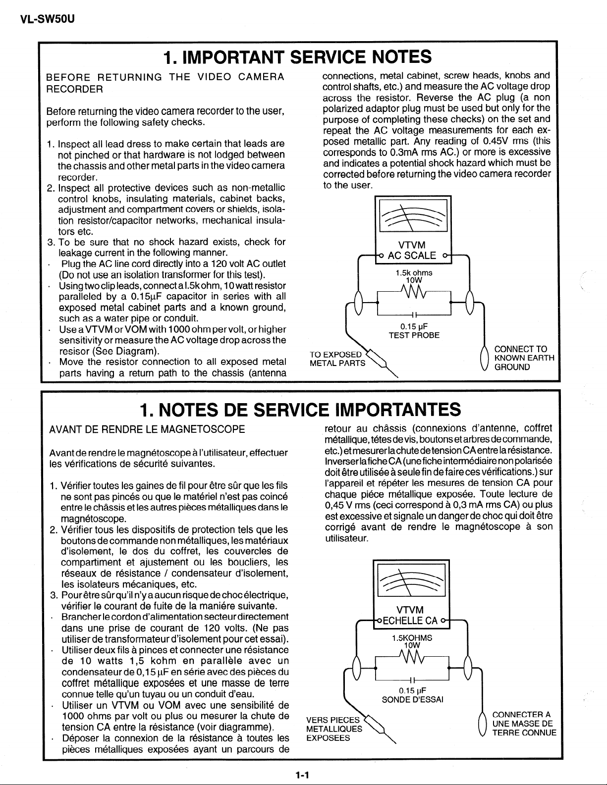
. Plug the AC line cord directly into a 120 volt AC outlet
(Do not use an isolation transformer for this test).
l Using two clip leads, connect a Kkohm, 10 watt resistor
paralleled by a 0.15pF capacitor in series with all
exposed metal cabinet parts and a known ground,
such as a water pipe or conduit.
. Use aVTVM or VOM with 1000 ohm pervolt, or higher
sensitivity or measure the AC voltage drop across the
resisor (See Diagram).
. Move the resistor connection to all exposed metal
parts having a return path to the chassis (antenna
connections, metal cabinet, screw heads, knobs and
control shafts, etc.) and measure the AC voltage drop
across the resistor. Reverse the AC plug (a non
polarized adaptor plug must be used but only for the
purpose of completing these checks) on the set and
repeat the AC voltage measurements for each exposed metallic part. Any reading of 0.45V rms (this
corresponds to 0.3mA rms AC.) or more is excessive
and indicates a potential shock hazard which must be
corrected before returning the video camera recorder
to the user.
TO EXP
METAL
CONNECT TO
KNOWN EARTH
GROUND
1. NOTES DE S RVICE IMPORTAhlTES
AVANT DE RENDRE LE MAGNETOSCOPE
Avant de rendre le magnetoscope a I’utilisateur, effectuer
les verifications de securite suivantes.
1. Verifier toutes les gaines de fil pour etre sur que les fils
ne sont pas pin&s ou que le materiel n’est pas coin&
entre le chassis et les autres pieces metalliques dans le
magnetoscope.
2. Verifier tous les dispositifs de protection tels que les
boutons de commande non metalliques, les materiaux
d’isolement, le dos du coffret, les couvercles de
compartiment et ajustement ou les boucliers, les
reseaux de resistance / condensateur d’isolement,
les isolateurs mecaniques, etc.
3. Pour etre sur qu’il n’y aaucun risque de choc electrique,
verifier le courant de fuite de la maniere suivante.
. Brancher lecordon d’alimentation secteurdirectement
dans une prise de courant de 120 volts. (Ne pas
utiliser de transformateur d’isolement pour cet essai).
. Utiliser deux fils a pinces et connecter une resistance
de IO watts I,5 kohm en parallele avec un
condensateur de 0,15 I_LF en serie avec des pieces du
coffret metallique exposees et une masse de terre
connue telle qu’un tuyau ou un conduit d’eau.
. Utiliser un VTVM ou VOM avec une sensibilite de
1000 ohms par volt ou plus ou mesurer la chute de
tension CA entre la resistance (voir diagramme).
. Deposer la connexion de la resistance a toutes les
pieces metalliques exposees ayant un parcours de
retour au chassis (connexions d’antenne, coffret
metallique, t&es devis, boutons et arbres decommande,
etc.) et mesurer lachute de tension CAentre la resistance.
Inverserlafiche CA (unefiche intermediaire non polarisee
doit etre utiliseeaseulefin defairecesverifications.) sur
I’appareil et repeter les mesures de tension CA pour
chaque piece metallique exposee. Toute lecture de
0,45 V rms (ceci correspond a 0,3 mA rms CA) ou plus
est excessive et signale un danger de choc qui doit etre
corrige avant de rendre le magnetoscope a son
utilisateur.
VERS PIECES
METALLIQUES
1-l
Page 3
vL-sw5ou
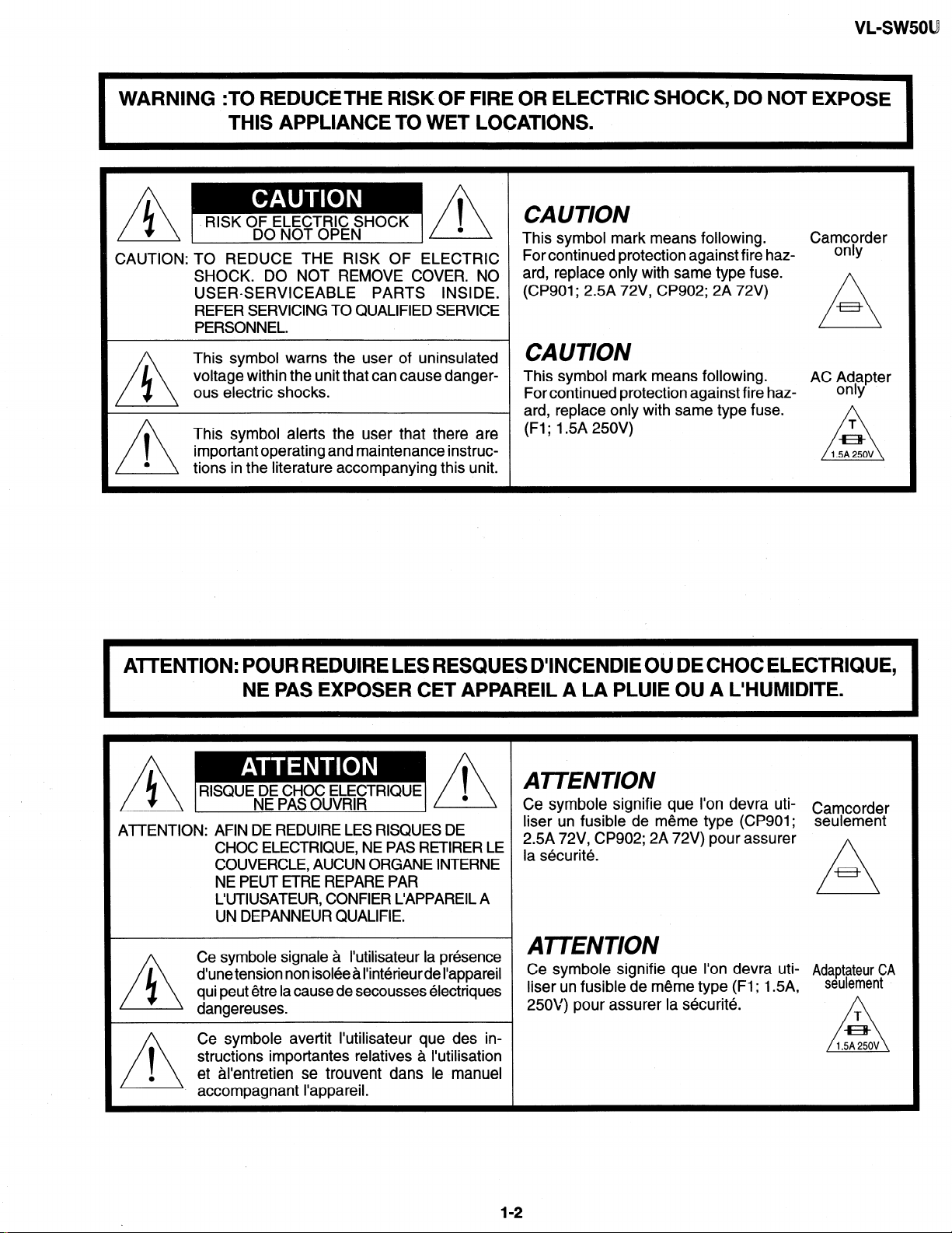
WARNING :TO REDUCETHE RISK OF FIRE OR ELECTRIC SHOCK, DO NOT EXPOSE
THIS APPLIANCE TO WET LOCATIONS.
1
A
AA
RISK OF ELECTRIC SHOCK
CAUTION: TO REDUCE THE RISK OF ELECTRIC
SHOCK. DO NOT REMOVE COVER. NO
USERSERVICEABLE PARTS INSIDE.
REFER SERVICING TO QUALIFIED SERVICE
PERSONNEL.
This symbol warns the user of uninsulated
voltage within the unit that can cause danger-
A
ous electric shocks.
This symbol alerts the user that there are
important operating and maintenance instruc-
tions in the literature accompanying this unit.
DO NOT OPEN
l
CAUTION
This symbol mark means following.
For continued protection against fire haz-
ard, replace only with same type fuse.
(CP901; 2.5A 72V, CP902; 2A 72V)
CAUTION
This symbol mark means following.
For continued protection against fire haz-
ard, replace only with same type fuse.
(Fl; 1.5A 250V)
Camcorder
only
AC Adapter
only
A
AmENTION: POUR REDUIRE LES RESQUES D’INCENDIE OU DE CHOC ELECTRIQUE,
NE PAS EXPOSER CET APPAREIL A LA PLUIE OU A L’HUMIDITE.
RISQUE DE CHOC ELECTRIQUE
ATTENTION: AFIN DE REDUIRE LES RISQUES DE
Ce symbole signale a I’utilisateur la presence
d’une tension non isolee a I’interieur de I’appareil
qui peut etre la cause de secousses electriques
dangereuses.
Ce symbole avertit I’utilisateur que des in-
I
0
n
structions importantes relatives a I’utilisation
et al’entretien se trouvent dans le manuel
accompagnant I’appareil.
NE PAS OUVRIR
CHOC ELECTRIQUE, NE PAS RETIRER LE
COUVERCLE, AUCUN ORGANE INTERNE
NE PEUT ETRE REPARE PAR
L’UTIUSATEUR, CONFIER L’APPAREIL A
UN DEPANNEUR QUALIFIE.
ATTENTION
Ce symbole signifie que t’on devra uti-
liser un fusible de meme type (CP901; seulement
2.5A 72V, CP902; 2A 72V) pour assurer
la securite.
Camcorder
n
AmENTION
Ce symbole signifie que I’on devra uti- Adapt&ur CA
liser un fusible de meme type (Fl; 1.5A,
25OV) pour assurer la securite.
seulement
12
I
Page 4
A CAUTION
BEFORE BATTERY DESTROY
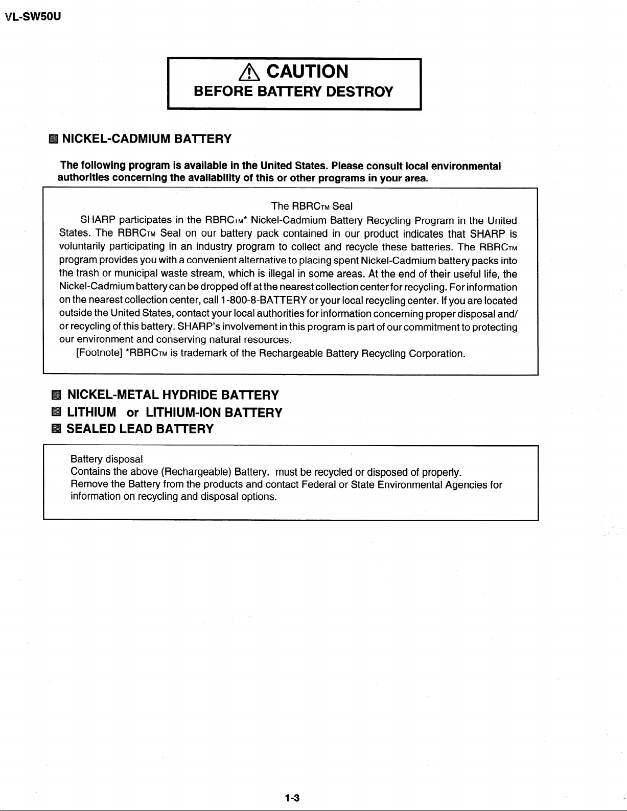
NICKEL-CADMIUM BATTERY
The following program is available in the United States. Please consult local environmental
authorities concerning the availability of this or other programs in your area.
The RBRCTM Seal
SHARP participates in the RBRCTM* Nickel-Cadmium Battery Recycling Program in the United
States. The RBRCTM Seal on our battery pack contained in our product indicates that SHARP is
voluntarily participating in an industry program to collect and recycle these batteries. The RBRCTM
program provides you with a convenient alternative to placing spent Nickel-Cadmium battery packs into
the trash or municipal waste stream, which is illegal in some areas. At the end of their useful life, the
Nickel-Cadmium battery can be dropped off at the nearest collection center for recycling. For information
on the nearest collection center, call I-800,8-BATTERY or your local recycling center. If you are located
outside the United States, contact your local authorities for information concerning proper disposal and/
or recycling of this battery. SHARP’s involvement in this program is part of our commitment to protecting
our environment and conserving natural resources.
[Footnote] *RBRCTM is trademark of the Rechargeable Battery Recycling Corporation.
NICKEL-METAL HYDRIDE BATTERY
LITHIUM or LITHIUM-ION BAlTERY
SEALED LEAD BATTERY
Battery disposal
Contains the above (Rechargeable) Battery. must be recycled or disposed of properly.
Remove the Battery from the products and contact Federal or State Environmental Agencies for
information on recycling and disposal options.
1-3
Page 5
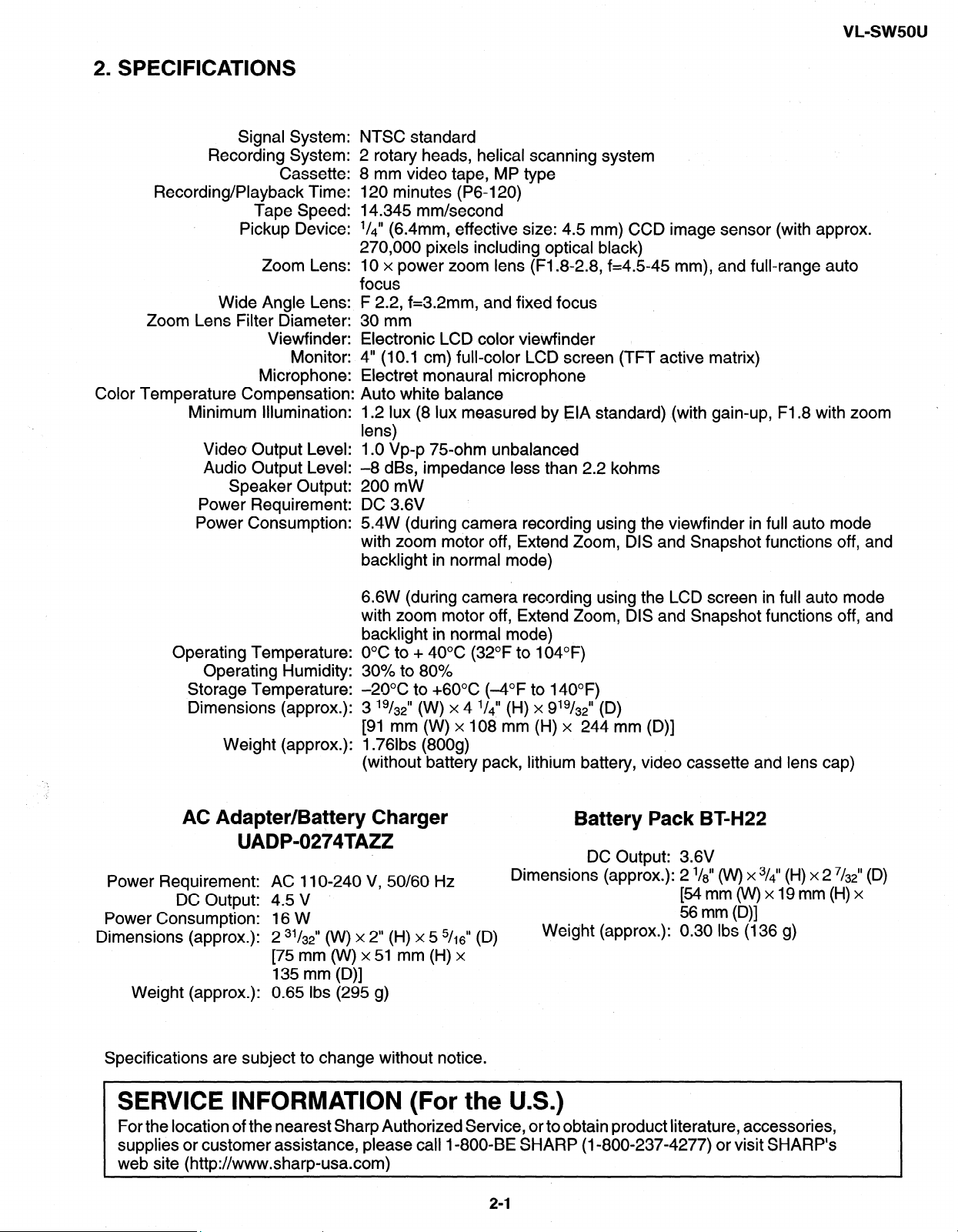
2. SPECIFICATIONS
VL-sw5ou
Signal System:
Recording System:
Cassette:
Recording/Playback Time:
Tape Speed:
Pickup Device:
Zoom Lens:
Wide Angle Lens:
Zoom Lens Filter Diameter:
Viewfinder:
Monitor:
Microphone:
Color Temperature Compensation:
Minimum Illumination:
Video Output Level:
Audio Output Level:
Speaker Output:
Power Requirement:
Power Consumption:
NTSC standard
2 rotary heads, helical scanning system
8 mm video tape, MP type
120 minutes (P6-120)
14.345 mm/second
l/d” (6 4mm effective size: 4.5 mm) CCD image sensor (with approx.
270,060 pixels including optical black)
10 x power zoom lens (Fl.8.2.8, f=4.5-45 mm), and full-range auto
focus
F 2.2, f=3.2mm, and fixed focus
,30mm
Electronic LCD color viewfinder
4” (10.1 cm) full-color LCD screen (TFT active matrix)
Electret monaural microphone
Auto white balance
1.2 lux (8 lux measured by EIA standard) (with gain-up, Fl.8 with zoom
lens)
1 .O Vp-p 75.ohm unbalanced
-8 dBs, impedance less than 2.2 kohms
200 mW
DC 3.6V
5.4W (during camera recording using the viewfinder in full auto mode
with zoom motor off, Extend Zoom, DIS and Snapshot functions off, and
backlight in normal mode)
6.6W (during camera recording using the LCD screen in full auto mode
with zoom motor off, Extend Zoom, DIS and Snapshot functions off, and
backlight in normal mode)
Operating Temperature:
Operating Humidity:
Storage Temperature:
Dimensions (approx.):
Weight (approx.):
O°C to + 40°C (32°F to 104°F)
30% to 80%
-2OOC to +6O”C (-4°F to 140°F)
3 ‘g/32” (W) x 4 ‘/41’ (H) x 9’9/32” (D)
191 mm (W) x 108 mm (H) x 244 mm (D)]
1.76lbs (800g)
(without battery pack, lithium battery, video cassette and lens cap)
AC Adapter/Battery Charger
UADP-0274TAZZ
Power Requirement: AC 1 IO-240 V, 50/60 Hz
DC Output: 4.5 V
Power Consumption: 16 W
Dimensions (approx.):
Weight (approx.): 0.65 Ibs (295 g)
2 31/3$’ (W) x 2” (H) x 5 5/16” (D)
[75 mm o(v) x 51 mm (H) x
135 mm (D)]
Battery Pack BT-H22
DC Output: 3.6V
Dimensions (approx.): 2 l/d’ o(v) x 3/<’ (H) x 2 7/&’ (D)
[54mm(W)xl9mm(H)x
56 mm (D)]
Weight (approx.): 0.30 Ibs (136 g)
Specifications are subject to change without notice.
SERVICE INFORMATION (For the U.S.)
For the location of the nearest Sharp Authorized Service, or to obtain product literature, accessories,
supplies or customer assistance, please call I-800-BE SHARP (I-800-237-4277) or visit SHARP’s
web site (http://www.sharp-usa.com)
2-1
Page 6
lSW5OU
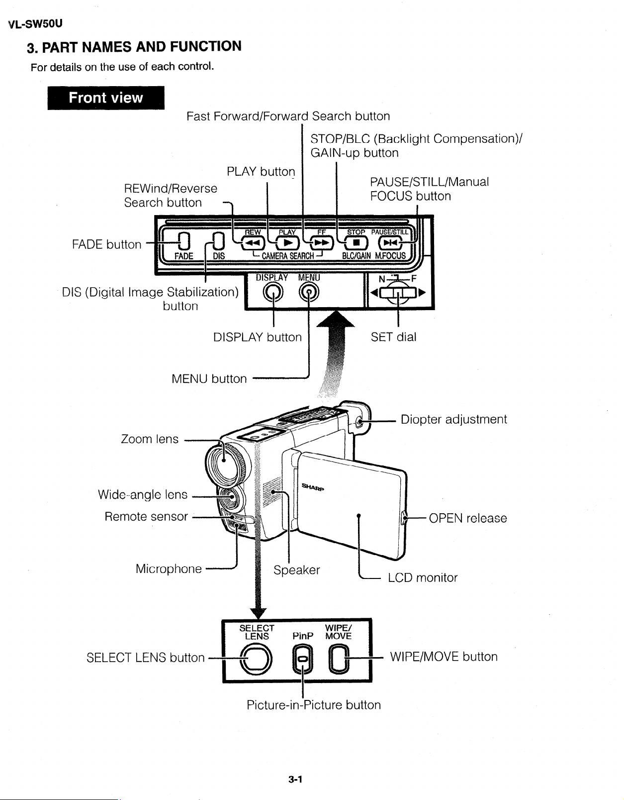
3. PART NAMES AND FUNCTION
For details on the use of each control.
Fast Forward/Forward Search button
REWind/Reverse
Search button
FADE button
DIS (Digital Image Stabi
buttor
MENU button
PLAY button
I
STOP/BLC (Backlight Corn
GAIN-up button
PAUSE/STILL/M
FOCUS button
Diopter adjustment
lpensation)/
anual
Remote sensor
SELECT LENS button
Speaker
I
I
Picture-in-Picture button
-OPEN release
LCD monitor
WIPE/MOVE button
Page 7
VL-sw5ou
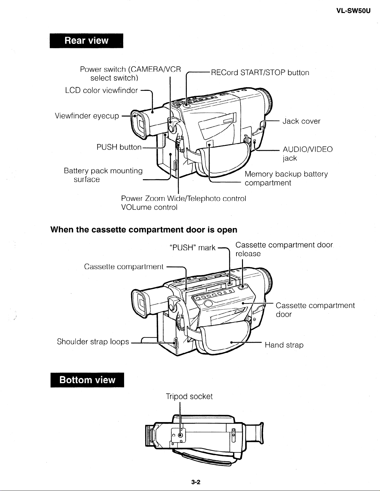
Power switch (CAMERA/VCR
select switch)
LCD color viewfinder h-1
.
VI
ewfind
Batter
When the cassette compartment door is open
er eyecup
y pack mounting
sur
face
t3scx
Power Zoom Wide/Telephoto control
VOLume control
1 I
--
- RECord START/STOP button
l
“PUSH” mark
- compartment
f& Jack cover
O/VIDEO
battery
Cassette compartment door
release
Cassette compartment
Shoulder strap loops
Tripod socket
Cassette
door
nd strap
compartment
3-2
Page 8
VL-swsou
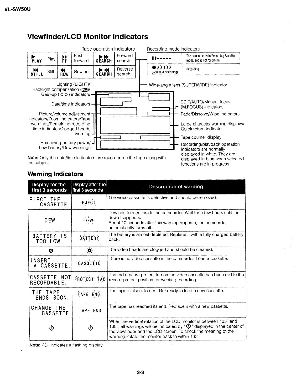
Viewfinder/LCD Monitor Indicators
.
b
PLAY Play F’: !%ard &sH ~~~~hd L ’ ‘lrn w m w w
HI
ST I LL ““’
Backlight compensation (m)/
Gain-up ( UXP) indicators -
Picture/volume adjustment
indicators/Zoom indicators/Tape
warnings/Remaining recording
time indicator/Clogged heads
Remaining battery power/
Low battery/Dew warnings
Note: Only the date/time indicators are recorded on the tape along with
the subject.
44
RE,,,, Rewind b*
I 1
Lighting (LIGHT)/
Date/time indicators
Tape operation indicators Recording mode indicators
l ))W
(Continuous flashing)
I
Wide-angle lens (SUPERWIDE) indicator
t
I
I 1
I I
. warnrng
Reverse
SEARCH search
I 1
I
l-----l -
-
-I_ -
J
_I
I
I
Warning Indicators
The camcorder is in Recording Standby
mode, and is not recording.
Recording
EDIT/AUTO/Manual focus
(M.FOCUS) indicators
r
-
Fade/Dissolve/Wipe indicators
Large-character warning displays/
-
Quick return indicator
-
Tape counter display
I
-
Recording/playback operation
indicators are normally
displayed in white. They are
displayed in blue when selected
functions are in progress.
:JECT THE
CASSETTE.
DEW
BATTERY IS '
T()() L ()W,
0
INSERT
A CASSETTE, ++S~T,TE’-
ZASSETTE NOT . ..PRijf&' ij(B_.
3 E COR DA B L E , a” 1 1 :’ \. .I.
THE TAPE a ' ’ ;
ENDS SOON, jk! E.;NP-’
_.'i j i 6 =f_.
XI t :'
. ..b EW .-
.J 1 i
._bAT&_.
.- / ! 5 ..-
I
: .*
. ...;&;.
i
t
. . ,+
CHANGE THE
The video cassette is defective and should be removed.
Dew has formed inside the camcorder. Wait for a few hours until the
dew disappears.
About IO seconds after this warning appears, the camcorder
automatically turns off.
The battery is almost depleted. Replace it with a fully charged battery
pack.
The video heads are clogged and should be cleaned.
I
There is no video cassette in the camcorder. Load a cassette.
The red erasure protect tab on the video cassette has been slid to the
record-protect position, preventing recording.
The tape is about to end. Get ready to load a new cassette.
The tape has reached its end. Replace it with a new cassette.
CASSETTE, TAPE END
When the vertical rotation of the LCD monitor is between 135” and
0
!
0
!
180°, all warnings will be indicated by ‘@” displayed in the center of
the viewfinder and the LCD screen. To check the meaning of the
warning, rotate the monitor back to within 135”.
I
I
Note: -1: I- indicates a flashing display.
33
I
Page 9
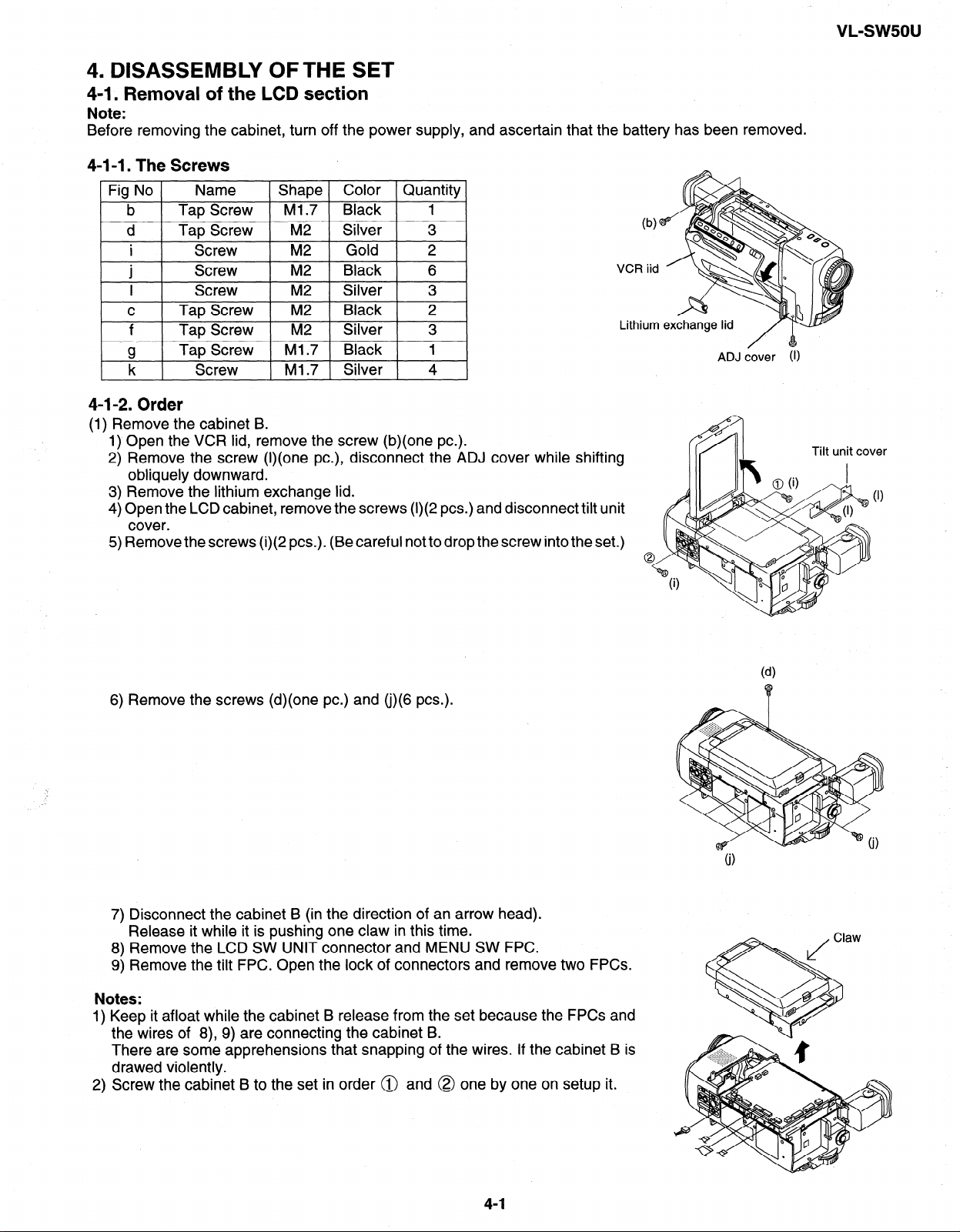
4. DISASSEMBLY OFTHE SET
4-l. Removal of the LCD section
Note:
Before removing the cabinet, turn off the power supply, and ascertain that the battery has been removed.
4-1-1. The Screws
Fig No
b
d Tap Screw M2 Silver 3
I
C
f Tap Screw M2
g
k Screw Ml .7 Silver 4
4-1-2. Order
(1) Remove the cabinet B.
1) Open the VCR lid, remove the screw (b)(one PC.).
2) Remove the screw (I)(one PC.), disconnect the ADJ cover while shifting
obliquely downward.
3) Remove the lithium exchange lid.
4) Open the LCD cabinet, remove the screws (I)(2 PCS.) and disconnect tilt unit
cover.
5) Remove the screws (i)(2 PCS.). (Be careful not to drop the screw into the set.)
Name Shape Color Quantity
Tap Screw Ml.7 Black 1
Screw
Screw
M2
M2
Screw M2
Tap Screw M2
Gold
Black
Silver 3
Black
Silver 3
Tap Screw
Ml .7 Black 1
2
6
VCR iid
2
Lithium exchange lid
ADJ
cover (1)
VL-sw5ou
’ .
Tilt unit cover
6) Remove the screws (d)(one PC.) and (j)(6 PCS.).
7) Disconnect the cabinet B (in the direction of an arrow head).
Release it while it is pushing one claw in this time.
8) Remove the LCD SW UNIT connector and MENU SW FPC.
9) Remove the tilt FPC. Open the lock of connectors and remove two FPCs.
Notes:
1) Keep it afloat while the cabinet B release from the set because the FPCs and
the wires of 8), 9) are connecting the cabinet B.
There are some apprehensions that snapping of the wires. If the cabinet B is
drawed violently.
2) Screw the cabinet B to the set in order @ and @ one by one on setup it.
4-1
Page 10
vL-sw5ou
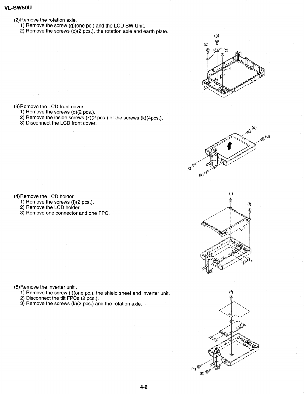
(2) Remove the rotation axle.
1) Remove the screw (g)(one PC.) and the LCD SW Unit.
2) Remove the screws (c)(2 PCS.), the rotation axle and earth plate.
(3)Remove the LCD front cover.
1) Remove the screws (d)(2 PCS.).
2) Remove the inside screws (k)(2 PCS.) of the screws (k)(4pcs.).
3) Disconnect the LCD front cover.
(4)Remove the LCD holder.
1) Remove the screws (f)(2 PCS.).
2) Remove the LCD holder.
3) Remove one connector and one FPC.
(5)Remove the inverter unit .
1) Remove the screw (f)(one PC.), the shield sheet and inverter unit.
2) Disconnect the tilt FPCs (2 PCS.).
3) Remove the screws (k)(2 PCS.) and the rotation axle.
4-2
Page 11
VL-SW5OU
Fig. No Name
C
d
.
J
Tap Screw M2
Tap Screw M2
Screw
I Screw
Shape Color Quantity
Black 3
Silver 1
M2
Black 1
_ M2 _ Silver _ 4
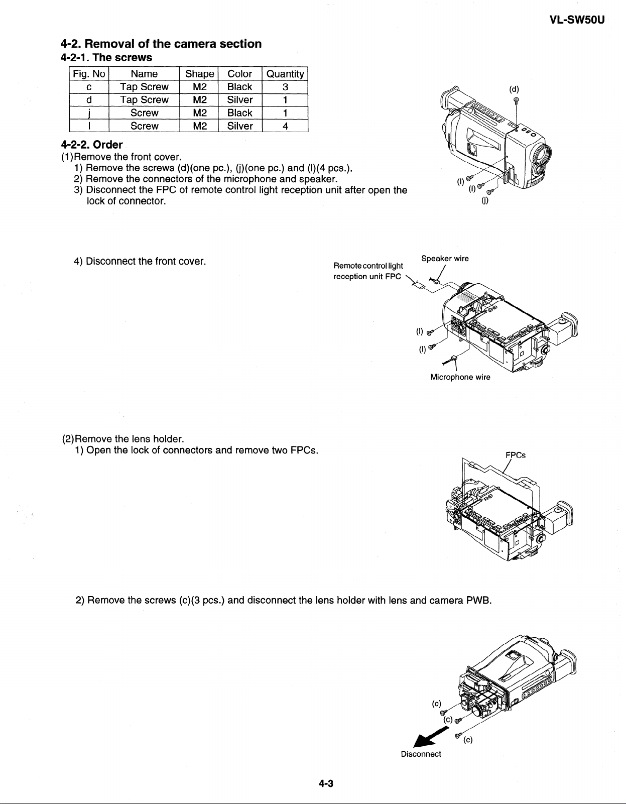
4-2-2. Order.
(1)Remove the front cover.
1) Remove the screws (d)(one PC.), (j)(one PC.) and (I)(4 PCS.).
2) Remove the connectors of the microphone and speaker.
3) Disconnect the FPC of remote control light reception unit after open the
lock of connector.
4) Disconnect the front cover.
Remote control light
reception unit FPC
Speaker wire
(2)Remove the lens holder.
1) Open the lock of connectors and remove two FPCs.
2) Remove the screws (c)(3 PCS.) and disconnect the lens holder with lens and camera PWB.
4-3
Disconnect
Page 12
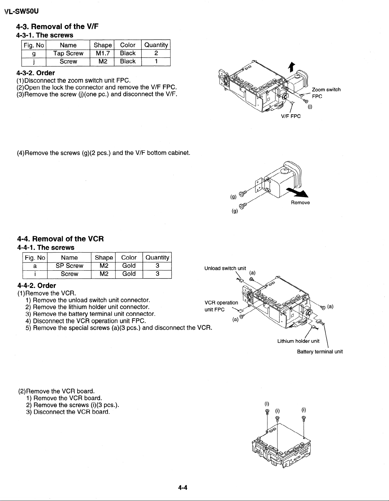
4-3. Removal of the V/F
4-3-1. The screws
Fig. No
g
l
I
4-3-2. Order
(1)Disconnect the zoom switch unit FPC.
(2)Open the lock the connector and remove the V/F FPC.
(3)Remove the screw (j)(one PC.) and disconnect the V/F.
(4)Remove the screws (g)(2 PCS.) and the V/F bottom cabinet.
Name Shape Color Quantity
Tap Screw
Screw
Ml .7 Black 2
M2 Black 1
Zoom switch
FPC
V/F FPC
4-4. Removal of the VCR
4-4-l. The screws
Fig. No
a SP Screw M2
i
4-4-2. Order
(l)Remove the VCR.
1) Remove the unload switch unit connector.
2) Remove the lithium holder unit connector.
3) Remove the battery terminal unit connector.
4) Disconnect the VCR operation unit FPC.
5) Remove the special screws (a)(3 PCS.) and discon
(2)Remove the VCR board.
1) Remove the VCR board.
2) Remove the screws (i)(3 PCS.).
3) Disconnect the VCR board.
Name
Shape Color Quantity
Screw M2
Gold
Gold 3
3
nect the V
Lithium holder unit
i
0
a
( 1
Battery terminal unit
\
4-4
Page 13
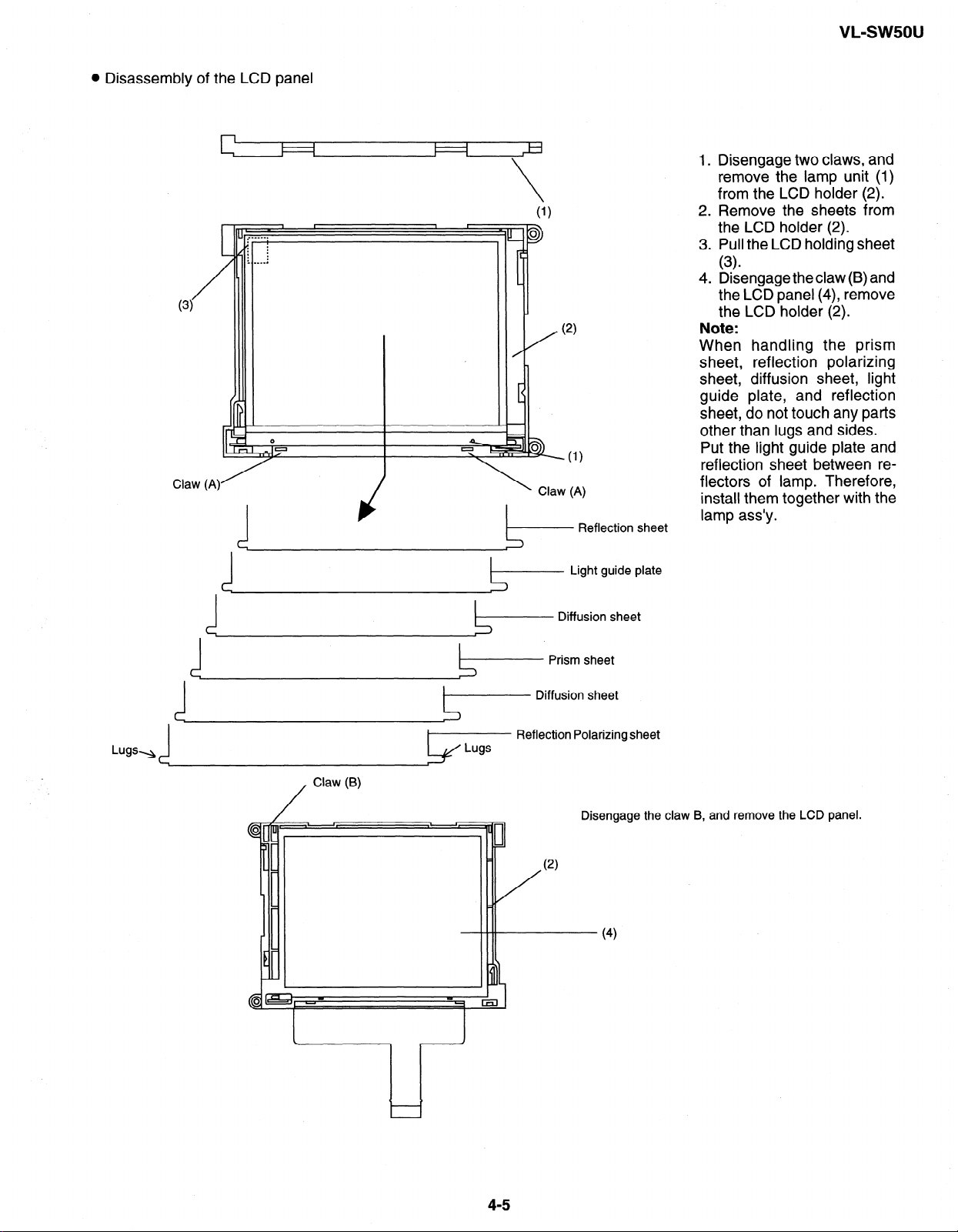
0 Disassembly of the LCD panel
VL-sw5ou
I I
I
I
Claw (A)
(- Reflection sheet
Light guide plate
1 .
Disengage two claws, and
remove the lamp unit (1)
from the LCD holder (2).
.
2
Remove the sheets from
the LCD holder (2).
.
3
Pull the LCD holding sheet
(3)
4.
Disengage the claw (B) and
the LCD panel (4), remove
the LCD holder (2).
Note:
When handling the prism
sheet, reflection polarizing
sheet, diffusion sheet, light
guide plate, and reflection
sheet, do not touch any parts
other than lugs and sides.
Put the light guide plate and
reflection sheet between re-
flectors of lamp. Therefore,
install them together with the
lamp ass’y.
Lugs-
1
/
Diffusion sheet
Prism sheet
Diffusion sheet
Reflection Polarizing sheet
Claw (6)
Disengage the claw B, and remove the LCD panel.
(2)
(4)
4-5
Page 14
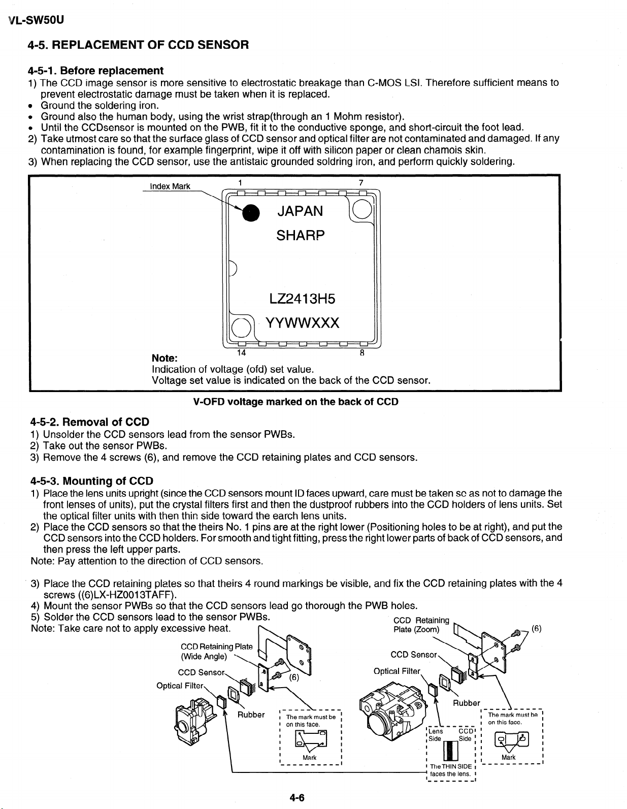
4-5. REPLACEMENT OF CCD SENSOR
4-5-l. Before replacement
The CCD image sensor is more sensitive to electrostatic breakage than CMOS LSI. Therefore sufficient means to
prevent electrostatic damage must be taken when it is replaced.
Ground the soldering iron.
Ground also the human body, using the wrist strap(through an 1 Mohm resistor).
Until the CCDsensor is mounted on the PWB, fit it to the conductive sponge, and short-circuit the foot lead.
Take utmost care so that the surface glass of CCD sensor and optical filter are not contaminated and damaged. If any
contamination is found, for example fingerprint, wipe it off with silicon paper or clean chamois skin.
When replacing the CCD sensor, use the antistaic grounded soldring iron, and perform quickly soldering.
Index Mark
LZ2413H5
L
.ct yywwxxx
Note:
Indication of voltage (ofd) set value.
Voltage set value is indicated on the back of the CCD sensor.
V-OFD voltage marked on the back of CCD
4-5-2. Removal of CCD
1) Unsolder the CCD sensors lead from the sensor PWBs.
2) Take out the sensor PWBs.
3) Remove the 4 screws (6), and remove the CCD retaining plates and CCD sensors.
4-5-3. Mounting of CCD
1) Place the lens units upright (since the CCD sensors mount ID faces upward, care must be taken SC as not to damage the
front lenses of units), put the crystal filters first and then the dustproof rubbers into the CCD holders of lens units. Set
the optical filter units with then thin side toward the earth lens units.
2) Place the CCD sensors so that the theirs No. 1 pins are at the right lower (Positioning holes to be at right), and put the
CCD sensors into the CCD holders. For smooth and tight fitting, press the right lower parts of back of CCD sensors, and
then press the left upper parts.
Note: Pay attention to the direction of CCD sensors.
’ 3) Place the CCD retaining plates so that theirs 4 round markings be visible, and fix the CCD retaining plates with th
screws ((6)LX_HZ0013TAFF).
4) Mount the sensor PWBs so that the CCD sensors lead go thorough the PWB holes.
5) Solder the CCD sensors lead to the sensor PWBs.
Note: Take care not to apply excessive heat.
CCD Retaining Plate
CCD Retainin
e4
\
._-___ ___I
I
I Themarkmust be :
1 on this face.
I
I
I
I
I
I
_1_____1-1
0
0
KJ
M&k
4-6
I
I
I
I
I
I
I
1 TheTHlNSlDE 1
I faces the lens. I
I
__--_-_-
I
Page 15
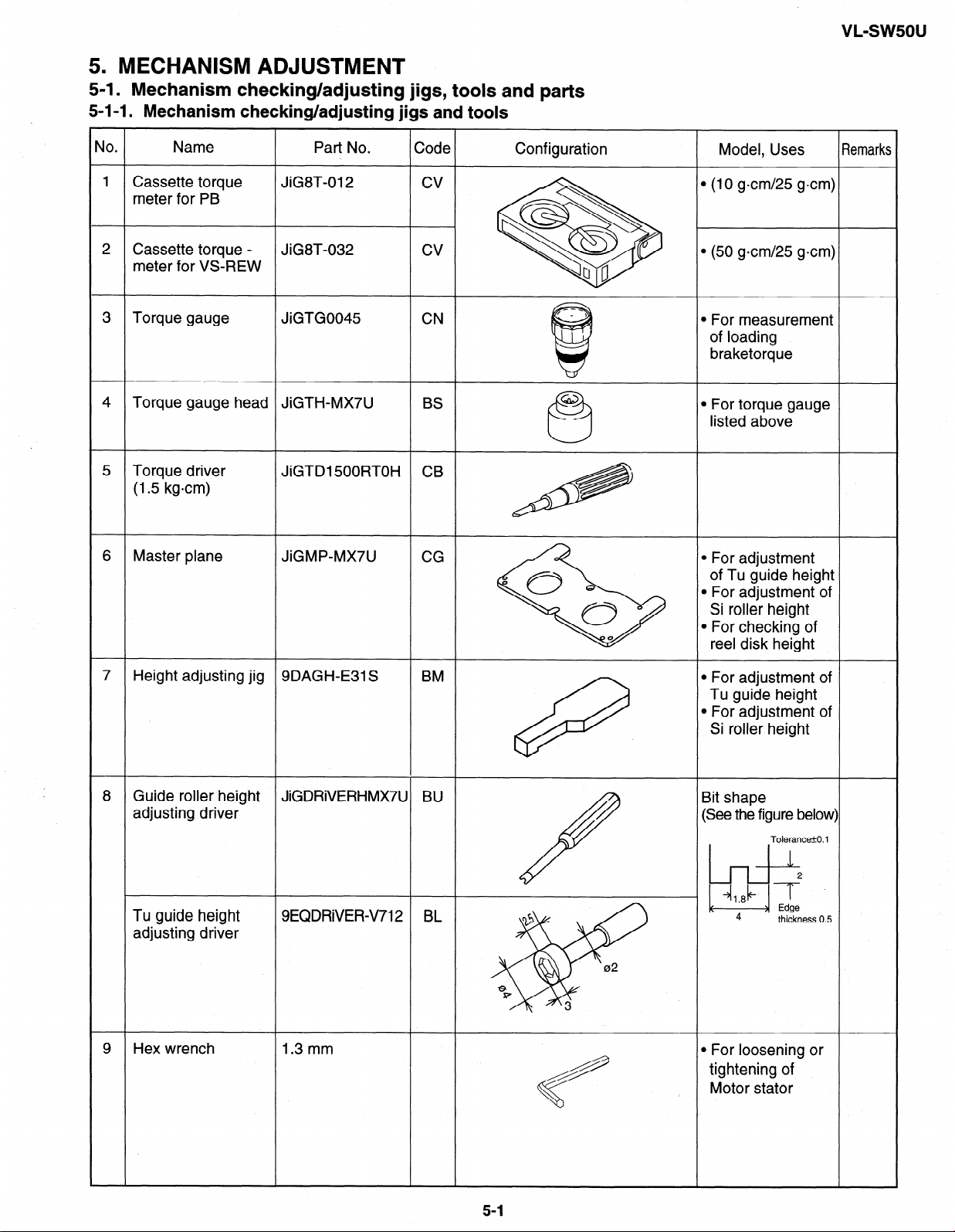
5. MECHANISM ADJUSTMENT
5-l. Mechanism checking/adjusting jigs, tools and parts
5-1-I. Mechanism checking/adjusting jigs and tools
VL=S\NSOU
l (10 g-cm/25 g=cm)
l (50 g-cm/25 g*cm)
l For measurement
Guide roller height
8
JiGDRiVERHMX7U BU
adjusting driver
Tu guide height 9EQDRiVEKV712 BL
adjusting driver
9 Hex wrench
1.3 mm l For loosening or
l For adjustment of
Si roller height
Bit shape
(See the figure below)
Tolerance&O. 1
/
4&b
I++/
15
02
8
17
+
3
2
Edge
thickness 0.5
tightening of
Motor stator
5-l
Page 16
Name
Part No.
Code
Configuration
Model, Uses
Remarks
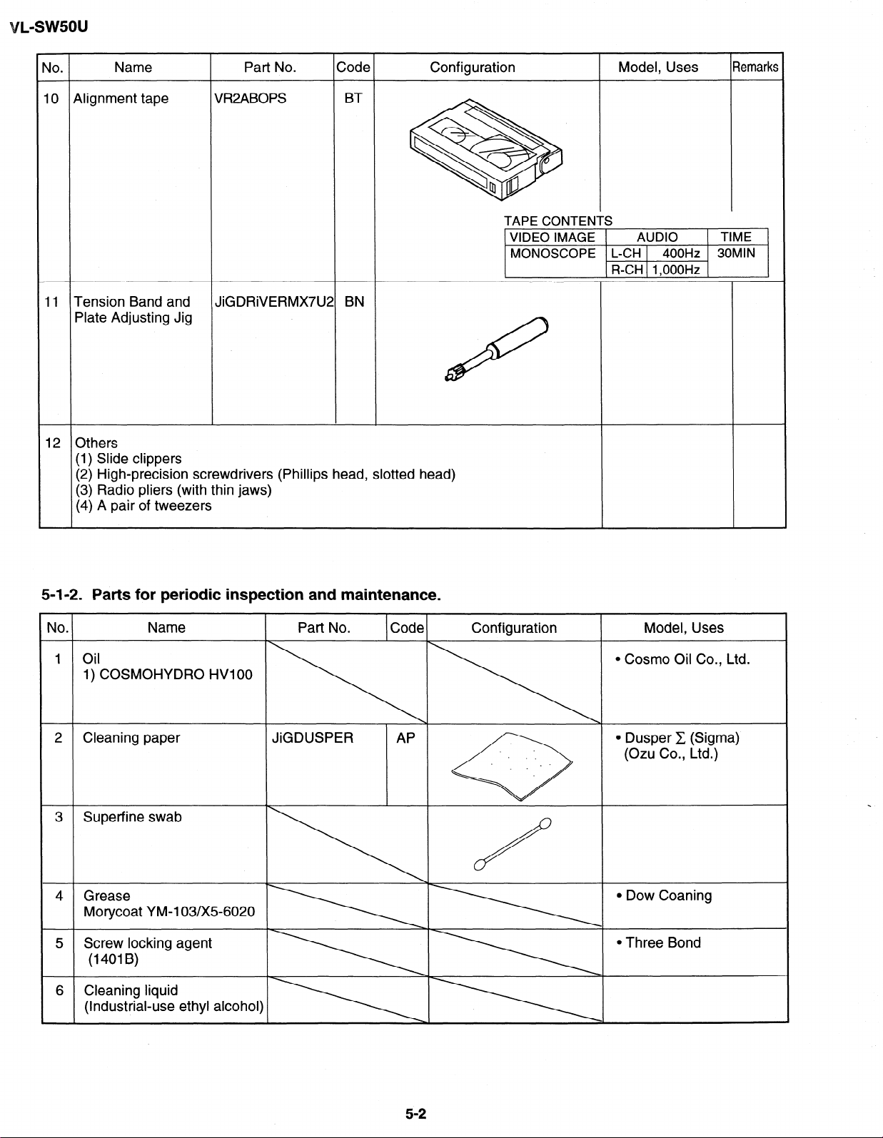
9lignment tape
11 Tension Band and
VR2ABOPS
JiGDRiVERMX7UZ
BT
BN
f
Plate Adjusting Jig
12
Others
(1) Slide clippers
(2) High-precision screwdrivers (Phillips head, slotted head)
(3) Radio pliers (with thin jaws)
(4) A pair of tweezers
TAPE CONTENTS
1 VIDEO IMAGE 1
MONOSCOPE L-CH
R-CH 1,OOOHz
AUDIO
400Hz 30MlN
1 TIME 1
5-1-2. Parts for periodic inspection and maintenance.
No
1
.
.
011
Name
1) COSMOHYDRO HVIOO
Cleaning paper
2
3 Superfine swab
4 Grease
Morycoat YM-103/X5-6020
Screw locking agent
5
(1401B)
6 Cleaning liquid
(Industrial-use ethyl alcohol]
Part No. Code
-\.\.\
I
JiGDUSPER AP
Configuration
Model, Uses
l Cosmo Oil Co., Ltd.
l Dusper C (Sigma)
(Ozu Co., Ltd.)
l Dow Coaning
l Three Bond
5-2
Page 17
VL-SW50U
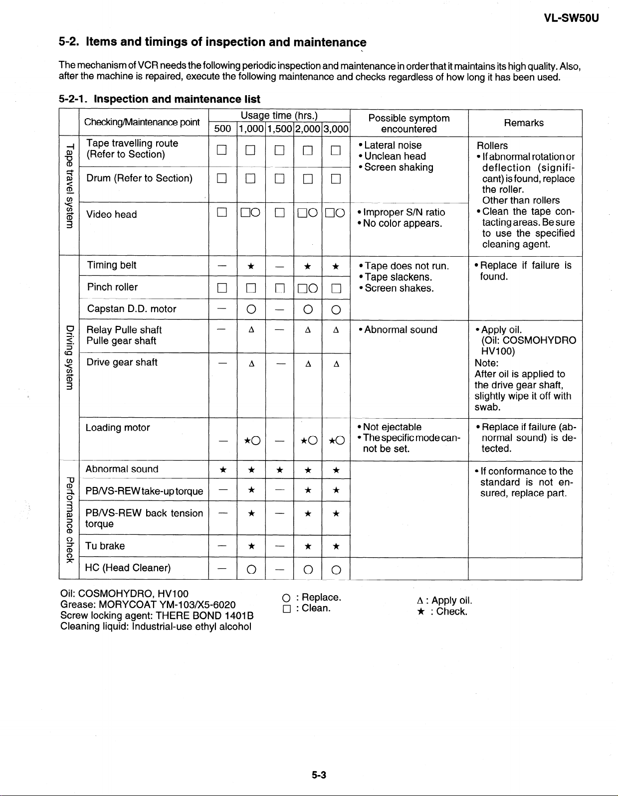
5-2. Items and timings of inspection and maintenance
.
The mechanism of VCR needs the following periodic inspection and maintenance in order that it maintains its high quality Also,
after the machine is repaired, execute the following maintenance and checks regardless of how long it has been used.
5-2-l. Inspection and maintenance list
Checking/Maintenance point
Tape travelling route
2
(Refer to Section)
CD
s L Drum (Refer to Section)
3
g Video head
3
Timing belt
Pinch roller
Capstan D.D. motor
CJ Relay Pulle shaft
2: Pulle gear shaft
cz
Drive gear shaft
3
il;
3
Usage time (hrs.)
500 1,000 1,500 2,000 3,000
0 0 0 0 0 $;;ran”;g;d
q cl q cl 0
0 00 q 00 00 *Improper S/N ratio
* - * *
0 0 0 00 0 *Screen shakes.
- 0 - () 0
A - A A
A - A A
Possible symptom
encountered
Remarks
Rollers
l If abnormal rotation or
l Screen shaking deflection (signifi-
cant) is found, replace
the roller.
. Other than rollers
*Clean the tape con-
l No color appears.
tatting areas. Be sure
to use the specified
cleaning agent.
*Tape does not run.
*Tape slackens.
@Abnormal sound
l Replace if failure is
found.
l Apply oil.
(Oil: COSMOHYDRO
HVI 00)
Note:
After oil is applied to
the drive gear shaft,
slightly wipe it off with
swab.
Loading motor
*o a
Abnormal sound
- *o -
* * * * *
a
?, PBNS-REWtake-uptorque - * - * *
g
2 PBA/S-REW back tension - * - * *
Z torque
CD
2 Tu brake
* - * *
%
HC (Head Cleaner)
Oil: COSMOHYDRO, HVI 00
Grease: MORYCOAT YM-103/X5-6020
Screw locking agent: THERE BOND 1401 B
0
0 0
0 : Replace.
0 : Clean.
Cleaning liquid: Industrial-use ethyl alcohol
l Not ejectable
l The specific mode can-
not be set.
A : Apply oil.
* : Check.
l Replace if failure (ab-
normal sound) is de-
tected.
* If conformance to the
standard is not ensured, replace part.
5-3
Page 18
5-2-2. Notes and cautions
(1) Any cut washers, once removed for parts replacement or for other reason, must be replaced with new ones.
(2) The mechanism of this VCR does not involve any volume adjustment. If the specified range is not satisfied, either
cleaning or replacing the parts is required.
(3) Oils
a) Be sure to use the specified oils (different viscosity may cause troubles).
b) For the bearings, be sure to use oil that is free form dust and other foreign substances. (Dust or foreign substance
contained in the oil may cause wear or seizure of the bearings.)
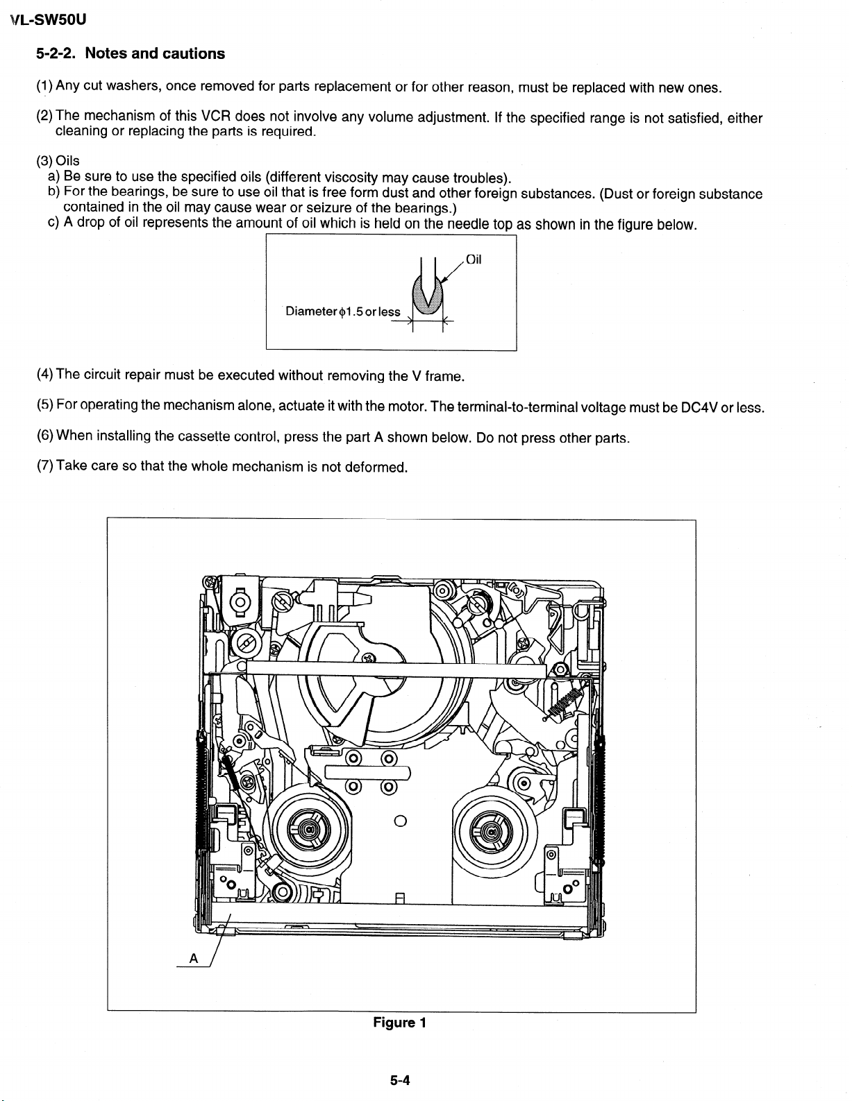
c) A drop of oil represents the amount of oil which is held on the needle top as shown in the figure below.
Oil
(4) The circuit repair must be executed without removing the V frame.
(5) For operating the mechanism alone, actuate it with the motor. The terminal-to-terminal voltage must be DC4V or less.
(6) When installing the cassette control, press the part A shown below. Do not press other parts.
(7) Take care so that the whole mechanism is not deformed.
A /
Figure 1
5-4
Page 19
VL-SWSOU
5-3. Mechanism checks and adjustments
The description given below relates to the general field services, but does not relate to the adjustment and replacement
that require high level equipments, jigs, and technical skills.
In order to maintain the initial characteristics of the machine, it is necessary to execute the maintenance and check and
to prevent damage to tapes and other parts. For adjustments which need jigs, be sure to use the jigs.
Notes and cautions
(1) For mechanism checks and adjustments, be sure to use the AC adapter as the power supply.
(2) For running the tape, be sure to install the cassette control ass’y in advance. (if the cassette control ass’y is to be
removed subsequently after its installation.)
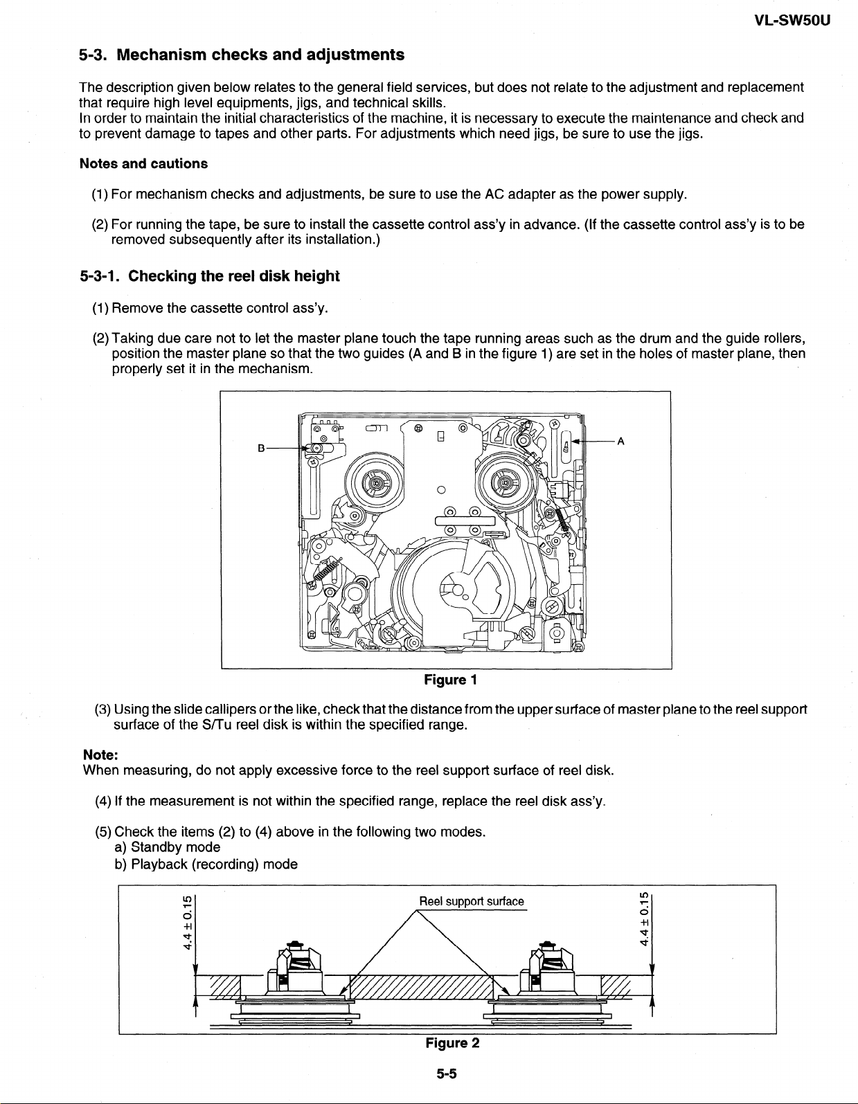
5-3-l. Checking the reel disk height
(1) Remove the cassette control ass’y.
(2) Taking due care not to let the master plane touch the tape running areas such as the drum and the guide rollers,
position the master plane so that the two guides (A and B in the figure 1) are set in the holes of master plane, then
properly set it in the mechanism.
B
Figure 1
(3) Using the slide callipers or the like, check that the distance from the upper surface of master plane to the reel support
surface of the Smu reel disk is within the specified range.
Note:
When measuring, do not apply excessive force to the reel support surface of reel disk.
(4) If the measurement is not within the specified range, replace the reel disk ass’y.
(5) Check the items (2) to (4) above in the following two modes.
a) Standby mode
b) Playback (recording) mode
A
Figure 2
Page 20
vL-sw5ou
5-3-2. Checking the take-up torque for playback (recording)
(1) Set the torque cassette (8T-012) in position, and check in the SP-mode recording mode (tape recorded in SP mode)
that the torque at the tape taking-up side is within the standard range.
Standard of take-up torque for SP-mode recording (playback)
9 +, 3 gem with ripples less than 4 gem
(If the torque ripples appear, read the center value of torque between the ripples.)
5-3-3. Checking and adjusting the back tension torque for playback (recording)
(1) Checking
1) Set the torque cassette (8T-012) in position, and check in the SP-mode recording mode (tape recorded in SP mode)
that the torque at the tape supply side is within the standard range.
Standard of back tension torque for SP-mode recording (playback):
8 & 2 gem with ripples of less than 2 gem
(Torque ripple must be within 8 + 2 gem)
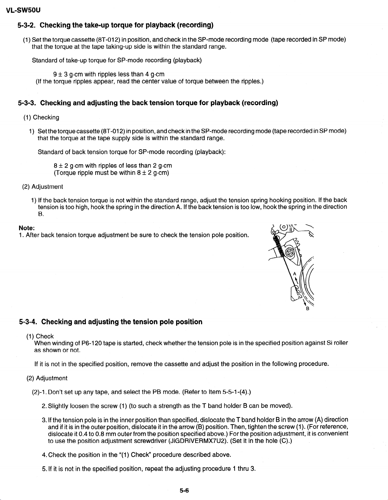
(2) Adjustment
1) If the back tension torque is not within the standard range, adjust the tension spring hooking position. If the back
tension is too high, hook the spring in the direction A. If the back tension is too low, hook the spring in the direction
.
B
Note:
1. After back tension torque adjustment be sure to check the tension pole position.
5-3-4. Checking and adjusting the tension pole position
(1) Check
When winding of P6-120 tape is started, check whether the tension pole is in the specified position against Si roller
as shown or not.
If it is not in the specified position, remove the cassette and adjust the position in the following procedure.
(2) Adjustment
(2)-l. Don’t set up any tape, and select the PB mode. (Refer to Item 5-5-l-(4).)
2. Slightly loosen the screw (1) (to such a strength as the T band holder B can be moved).
3. If the tension pole is in the inner position than specified, dislocate the T band holder B in the arrow (A) direction
and if it is in the outer position, dislocate it in the arrow (B) position. Then, tighten the screw (1). (For reference,
dislocate it 0.4 to 0.8 mm outer from the position specified above.) For the position adjustment, it is convenient
to use the position adjustment screwdriver (JiGDRiVERMX7U2). (Set it in the hole (C).)
4.Check the position in the “(1) Check” procedure described above.
5. If it is not in the specified position, repeat the adjusting procedure 1 thru 3.
5-6
Page 21
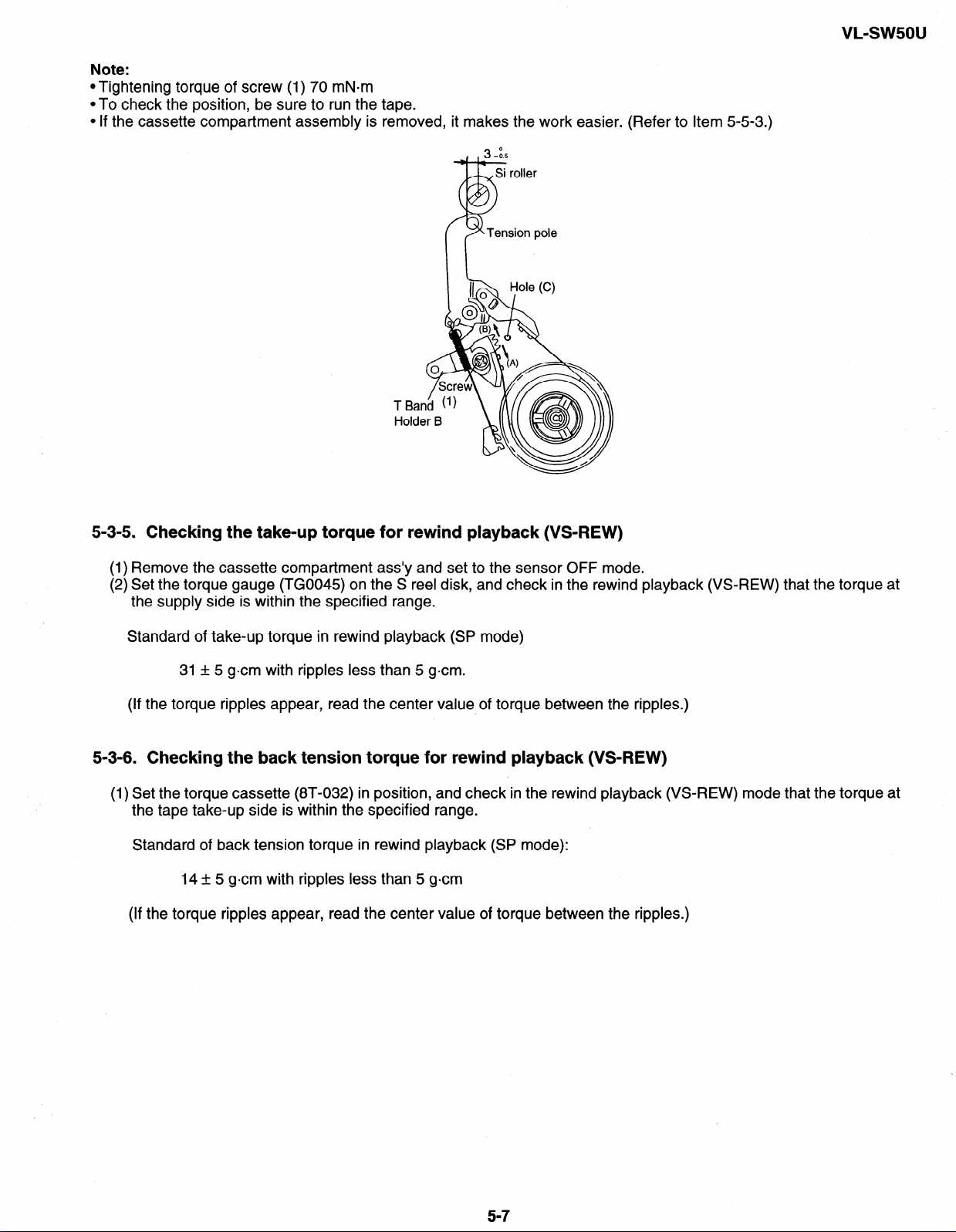
Note:
*Tightening torque of screw (1) 70 mN-m
*To check the position, be sure to run the tape.
l If the cassette compartment assembly is removed, it makes the work easier. (Refer to Item 5-5-3.)
VL-sw5ou
5-3-5. Checking the take-up torque for rewind playback (VS-REW)
(1) Remove the cassette compartment ass’y and set to the sensor OFF mode.
(2) Set the torque gauge (TG0045) on the S reel disk, and check in the rewind playback (VS-REW) that the torque at
the supply side is within the specified range.
Standard of take-up torque in rewind playback (SP mode)
31 & 5 gem with ripples less than 5 gem.
(If the torque ripples appear, read the center value of torque between the ripples.)
5-3-6. Checking the back tension torque for rewind playback (VS-REW)
(1) Set the torque cassette (8T-032) in position, and check in the rewind playback (VS-REW) mode that the torque at
the tape take-up side is within the specified range.
Standard of back tension torque in rewind playback (SP mode):
14 + 5 gem with ripples less than 5 gem
(If the torque ripples appear, read the center value of torque between the ripples.)
5-7
Page 22
VL-swsou
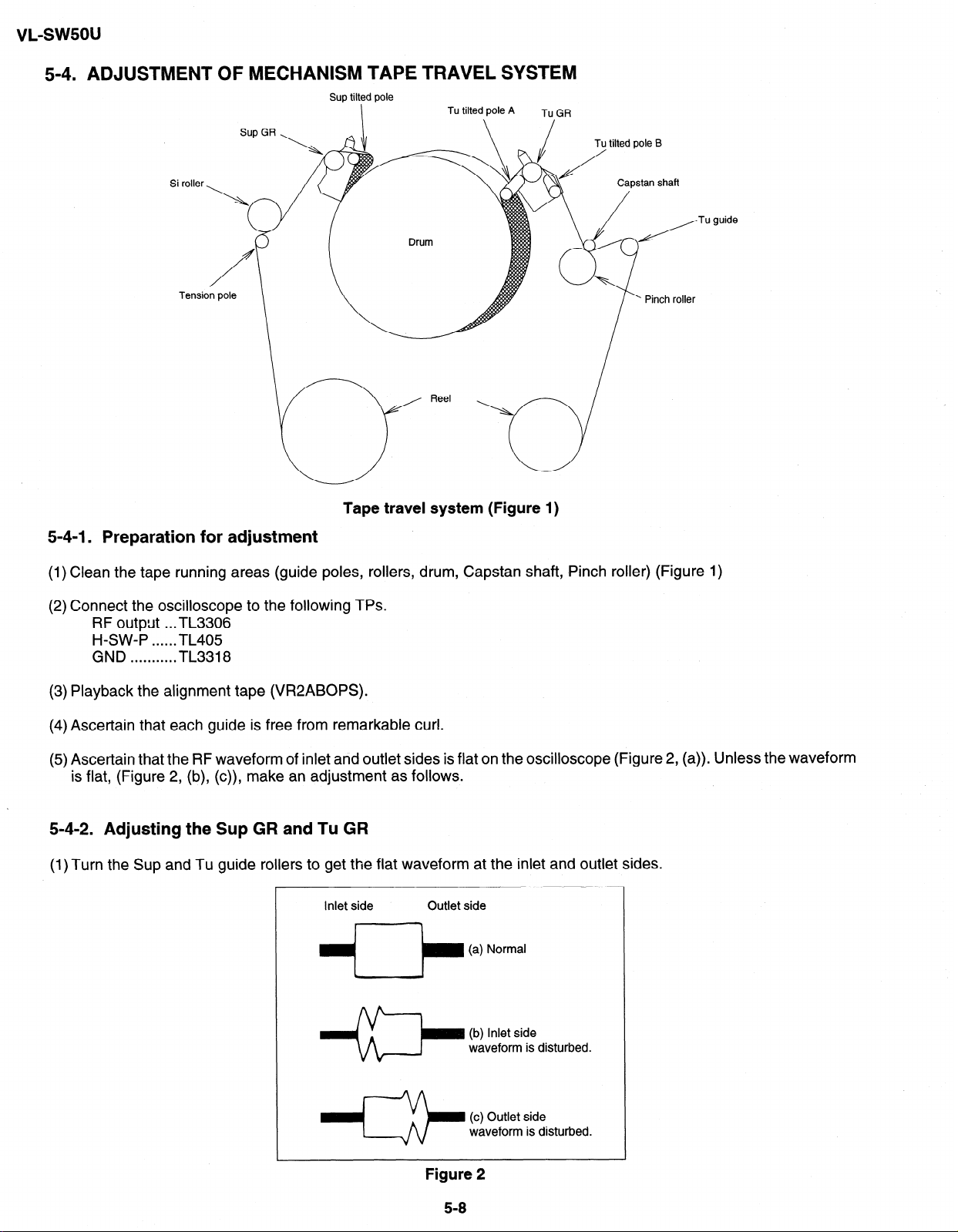
5-4. ADJUSTMENT OF MECHANISM TAPE TRAVEL SYSTEM
Sup tilted pole
Tu guide
Tape travel system (Figure 1)
5-4-l. Preparation for adjustment
(1) Clean the tape running areas (guide poles, rollers, drum, Capstan shaft, Pinch roller) (Figure 1)
(2) Connect the oscilloscope to the following TPs.
RF output . ..TL3306
H-SW-P . . . . ..TL405
GND . . . . . . . . . . . TL3318
(3) Playback the alignment tape (VR2ABOPS).
(4) Ascertain that each guide is free from remarkable curl.
(5) Ascertain that the RF waveform of inlet and outlet sides is flat on the oscilloscope (Figure 2, (a)). Unless the waveform
is flat, (Figure 2, (b), (c)), make an adjustment as follows.
5-4-2. Adjusting the Sup GR and Tu GR
(1) Turn the Sup and Tu guide rollers to get the flat waveform at the inlet and outlet sides.
Figure 2
5-8
Page 23
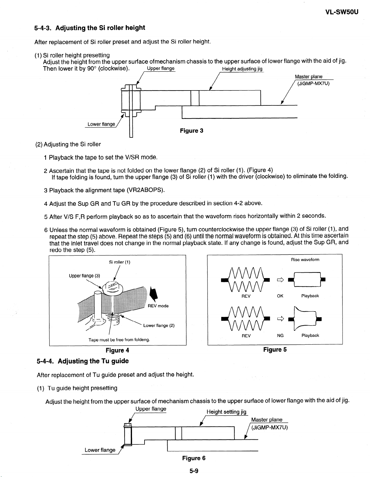
5-4-3. Adjusting the Si roller height
After replacement of Si roller preset and adjust the Si roller height.
(1) Si roller height presetting
Adjust the height from the upper surface ofmechanism chassis to the upper surface of lower flange with the aid of jig.
Then lower it by 90’ (clockwise).
Upper flange
Figure 3
(2) Adjusting the Si roller
1 Playback the tape to set the V/SR mode.
2 Ascertain that the tape is not folded on the lower flange (2) of Si roller (1). (Figure 4)
If tape folding is found, turn the upper flange (3) of Si roller (1) with the driver (clockwise) to eliminate the folding.
Height adjusting jig
Master plane
/w
VL-sw5ou
3 Playback the alignment tape (VR2ABOPS).
4 Adjust the Sup GR and Tu GR by the procedure described in section 4-2 above.
5 After V/S F,R perform playback so as to ascertain that the waveform rises horizontally within 2 seconds.
6 Unless the normal waveform is obtained (Figure 5), turn counterclockwise the upper flange (3) of Si roller (I), and
repeat the step (5) above. Repeat the steps (5) and (6) until the normal waveform is obtained. At this time ascertain
that the inlet travel does not change in the normal playback state. If any change is found, adjust the Sup GR, and
redo the step (5).
NG
Rise waveform
Playback
Upper flange (3)
. /
Tape must be free from foldeng.
Si roller (1)
Figure 4
REV
+%%I&
REV
Figure 5
5-4-4. Adjusting the Tu guide
After replacement of Tu guide preset and adjust the height.
(1) Tu guide height presetting
Adjust the height from the upper surface of mechanism chassis to the upper surface of lower flange with the aid of jig.
Upper flange
i---
jHeight setWI its Master p,ane
(JiGMP-MX7U)
I
Lower flange
Figure 6
5-9
Page 24
VL-sw5ou
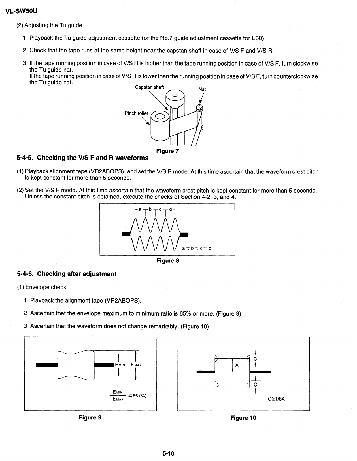
(2) Adjusting the Tu guide
1 Playback the Tu guide adjustment cassette (or the No.7 guide adjustment cassette for E30).
2 Check that the tape runs at the same height near the capstan shaft in case of V/S F and V/S R.
3 If the tape running position in case of V/S R is higher than the tape running position in case of V/S F, turn clockwise
the Tu guide nat.
If the tape running position in case of V/S R is lower than the running position in case of V/S F, turn counterclockwise
the Tu guide nat.
Pinch roller
I
Figure 7
5-4-5. Checking the V/S F and R waveforms
(1) Playback alignment tape (VR2ABOPS), and set the V/S R mode. At this time ascertain that the waveform crest pitch
is kept constant for more than 5 seconds.
(2) Set the V/S F mode. At this time ascertain that the waveform crest pitch is kept constant for more than 5 seconds.
Unless the constant pitch is obtained, execute the checks of Section 4-2, 3, and 4.
taTbTcTdl
Figure 8
5-4-6. Checking after adjustment
(1) Envelope check
1 Playback the alignment tape (VR2ABOPS).
2 Ascertain that the envelope maximum to minimum ratio is 65% or more. (Figure 9)
3 Ascertain that the waveform does not chanae remarkably. (Figure 10)
- EMIN EMAX
EMIN
- 2 65 (%)
EMAX
Figure 10 Figure 9
5-l 0
Page 25
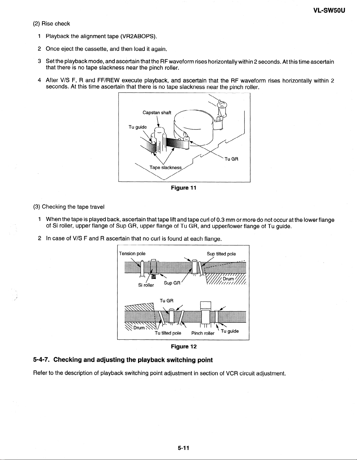
(2) Rise check
Playback the alignment tape (VR2ABOPS).
Once eject the cassette, and then load it again.
Set the playback mode, and ascertain that the RF waveform rises horizontally within 2 seconds. At this time ascertain
that there is no tape slackness near the pinch roller.
After V/S F, R and FF/REW execute playback, and ascertain that the RF waveform rises horizontally within 2
seconds. At this time ascertain that there is no tape slackness near the pinch roller.
Tu
cl’
/
GR
VL-swsou
Figure 11
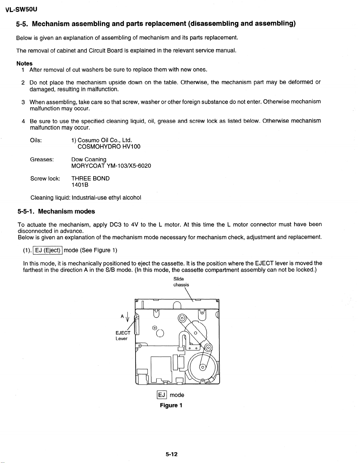
(3) Checking the tape travel
1 When the tape is played back, ascertain that tape lift and tape curl of 0.3 mm or more do not occur at the lower flange
of Si roller, upper flange of Sup GR, upper flange of Tu GR, and upper/lower flange of Tu guide.
2 In case of V/S F and R ascertain that no curl is found at each flange.
Tension pole
Tu tilted pole
Sup tilted pole
Pinch roller
’
Tu guide
Figure 12
5-4-7. Checking and adjusting the playback switching point
Refer to the description of playback switching point adjustment in section of VCR circuit adjustment.
5-l 1
Page 26
vL-sw5ou
5-5. Mechanism assembling and parts replacement (disassembling and assembling)
Below is given an explanation of assembling of mechanism and its parts replacement.
The removal of cabinet and Circuit Board is explained in the relevant service manual.
After removal of cut washers be sure to replace them with new ones.
Do not place the mechanism upside down on the table. Otherwise, the mechanism part may be deformed or
damaged, resulting in malfunction.
When assembling, take care so that screw, washer or other foreign substance do not enter. Otherwise mechanism
malfunction may occur.
Be sure to use the specified cleaning liquid, oil, grease and screw lock as listed below. Otherwise mechanism
malfunction may occur.
Oils: 1) Cosumo Oil Co., Ltd.
COSMOHYDRO HVlOO
Greases: Dow Coaning
MORYCOAT YM-103/X5-6020
Screw lock:
Cleaning liquid: Industrial-use ethyl alcohol
THREE BOND
14018
5-5-l. Mechanism modes
To actuate the mechanism, apply DC3 to 4V to the L motor. At this time the L motor connector must have been
disconnected in advance.
Below is given an explanation of the mechanism mode necessary for mechanism check, adjustment and replacement.
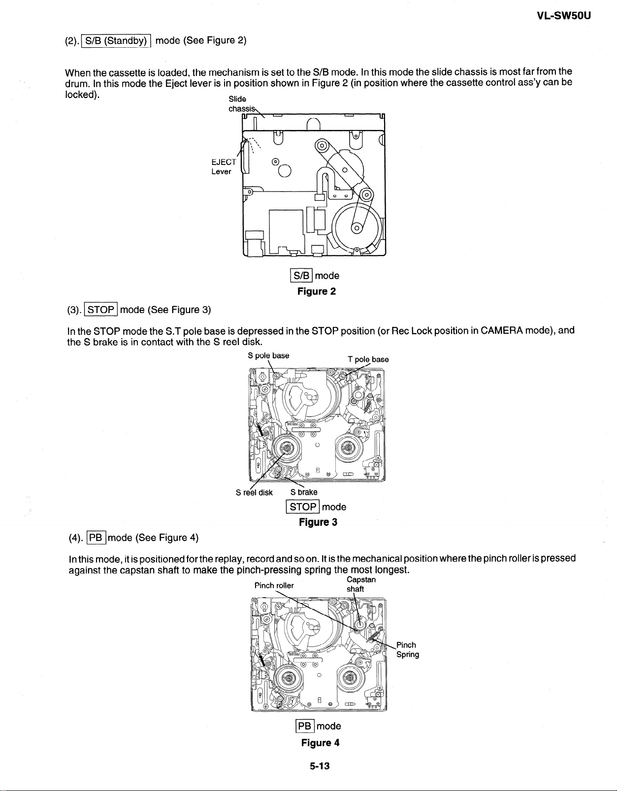
(1). I] mode (See Figure 1)
In this mode, it is mechanically positioned to eject the cassette. It is the position where the EJECT lever is moved the
farthest in the direction A in the S/B mode. (In this mode, the cassette compartment assembly can not be locked.)
Slide
chassis
EJ mode
cl
Figure 1
5-12
Page 27
VL-SW5OU
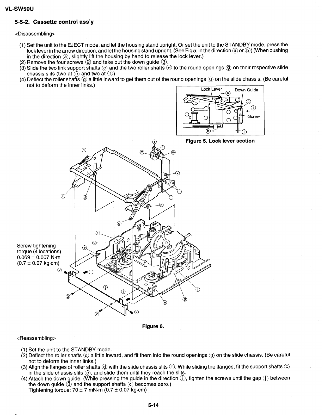
(2).( S/B (Standby)
When the cassette is loaded, the mechanism is set to the S/B mode. In this mode the slide chassis is most far from the
drum. In this mode the Eject lever is in position shown in Figure 2 (in position where the cassette control ass’y can be
locked).
(3). ml mode (See Figure 3)
mode (See Figure 2)
Slide
EJECT
Lever
S/B mode
I
Figure 2
In the STOP mode the ST pole base is depressed in the STOP position (or Ret Lock position in CAMERA mode), and
the S brake is in contact with the S reel disk.
Sr
STOP mode
Figure 3
(4). (PBlmode (See Figure 4)
In this mode, it is pos
against the capstan
itioned for the replay,
shaft to make the pi
record and so on. It is the mechanical position
rich-pressing spring the most longest.
Pinch roller
Capstan
shaft
where the pinch roller is pressed
PB mode
L-l
Figure 4
5-13
-Pinch
Spring
Page 28
VL-swsou
5-5-2. Cassette control ass’y
<Disassembling>
(1) Set the unit to the EJECT mode, and let the housing stand upright. Or set the unit to the STANDBY mode, press the
lock lever in the arrow direction, and let the housing stand upright. (See Fig 5: in the direction @ or @) (When pushing
in the direction @, slightly lift the housing by hand to release the lock lever.)
(2) Remove the four screws @ and take out the down guide @.
(3) Slide the two link support shafts @ and the two roller shafts @ to the round openings @ on their respective slide
chassis slits (two at @ and two at 0).
(4) Deflect the roller shafts @ a little inward to get them out of the round openings (@on the slide chassis. (Be careful
not to deform the inner links.)
Lock Lever
Down Guide
Screw tightening
torque (4 locations)
0.069 & 0.007 Nom
(0.7 1: 0.07 kgcm)
Q
I
Figure 5. Lock lever section
Figure 6.
<Reassembling>
(1) Set the unit to the STANDBY mode.
(2) Deflect the roller shafts @ a little inward, and fit them into the round openings @ on the slide chassis. (Be careful
not to deform the inner links.)
(3) Align the flanges of roller shafts @ with the slide chassis slits 0. While sliding the flanges, fit the support shafts @
in the slide chassis slits @, and slide them until they reach the slits.
(4) Attach the down
the down guide 3 and the support shafts @ becomes zero.)
uide. (While pressing the guide in the direction 0, tighten the screws until the gap 0 between
P,
Tightening torque: 70 + 7 mN*m (0.7 * 0.07 kgcm)
5-14
Page 29
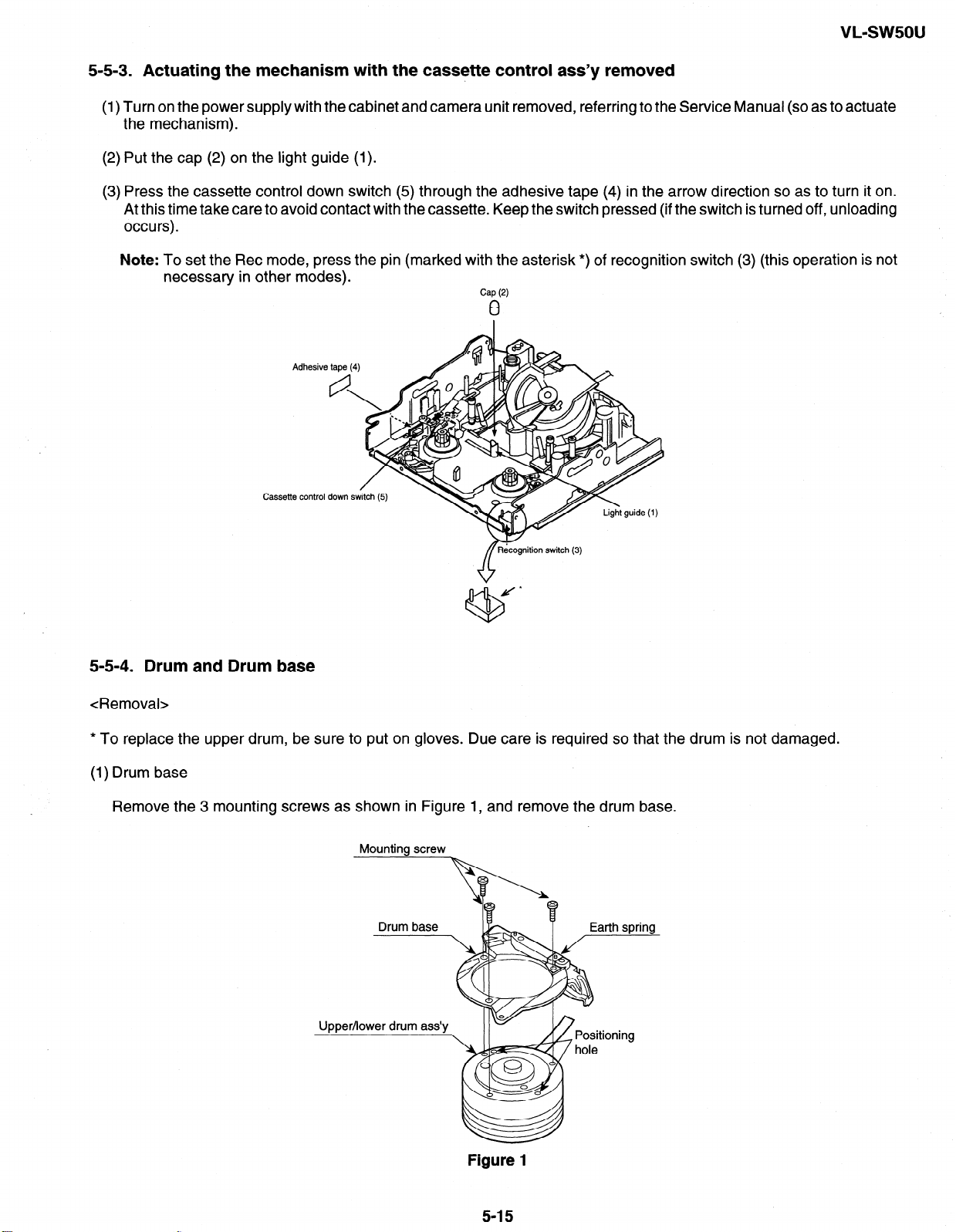
5-5-3. Actuating the mechanism with the cassette control ass’y removed
(1) Turn on the power supply with the cabinet and camera unit removed, referring to the Service Manual (so as to actuate
the mechanism).
(2) Put the cap (2) on the light guide (1).
(3) Press the cassette control down switch (5) through the adhesive tape (4) in the arrow direction so as to turn it on.
At this time take care to avoid contact with the cassette. Keep the switch pressed (if the switch is turned off, unloading
occurs).
Note: To set the Ret mode, press the pin (marked with the asterisk *) of recognition switch (3) (this operation is not
necessary in other modes).
Cassette control
Cap (2)
0
5-5-4. Drum and Drum base
<Removal>
* To replace the upper drum, be sure to put on gloves. Due care is required so that the drum is not damaged.
(1) Drum base
Remove the 3 mounting screws as shown in Figure 1, and remove the drum base.
Mounting screw
Figure 1
5-l 5
Page 30
VL-SWSOU
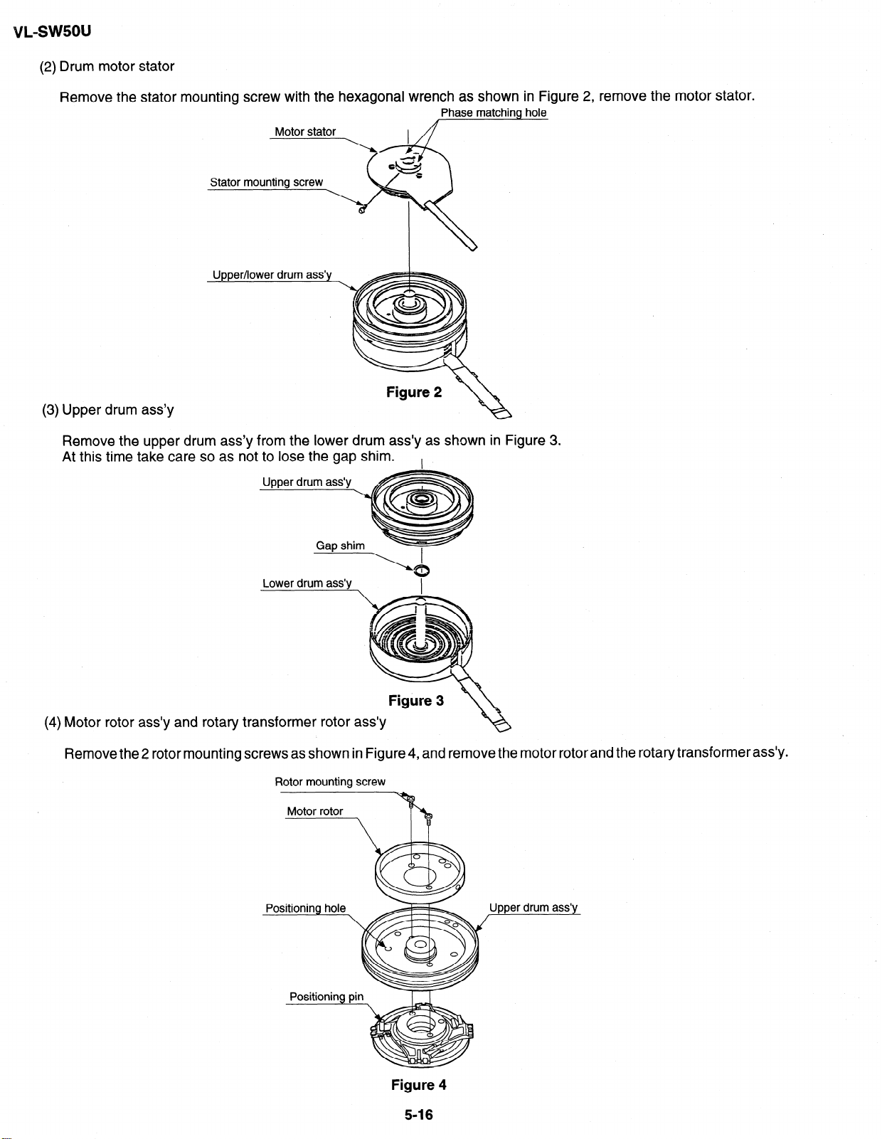
(2) Drum motor stator
Remove the stator mounting
screw with the hexagonal wrench as shown
Stator
Upper/lower drum ass’y
Figure 2
(3) Upper drum ass’y
Remove the upper drum ass’y from the lower drum ass’y as shown
At this time take care so as not to lose the gap shim.
I
Phase matching
\
in Figure 3.
in Figure
hole
2, remove the motor stator.
Lower drum ass’y
\
I
Figure 3
Motor rotor ass’y and rotary transformer rotor ass’y
Remove the 2 rotor mounting screws as shown in Figure 4, and remove the motor rotor and the rotary transformer ass’y.
Rotor mounting screw
I
drum ass’v
Figure 4
5-16
Page 31

(5) Balancer
Remove the balancer mounting screw as shown in Figure 5, and remove the balancer.
BTancer mounting screw ~ /Ba,ancer
Upper drum ass’y
Figure 5
(6) Lower drum ass’y
Remove the FPC mounting screw from the lower drum ass’y as shown in Figure 6.
FPC mounting screw
Lower drum ass’y
VL-swsou
Figure 6
<Installation>
Install the upper drum in the reverse order of removal.
(1) Balancer
Mount the balancer to the upper drum ass’y with the balancer mounting screw. The screw tightening torque must be
0.1 N-m (tighting torque 1 kgcm). (Figure 5)
(2) Motor rotor, rotary transformer rotor ass’y
Clean the contact surfaces of rotor ass’y holder and upper drum ass’y, and ascertain that there are no contamination
and flaws.
Next, adjust the phase so that the positioning pin of rotor ass’y is inserted into the positioning hole of upper drum, and
tight fit the rotor ass’y to the lower surface of upper drum ass’y (Figure 7).
Mounting screw hole
Rotary transformer
Rotor ass’y
Rotary transformer
rotor
with
position pin.
Figure 7
5-17
Page 32

In this state put the motor rotor on the upper surface of upper drum ass’y, and tighten the mounting screw. At this time
make sure that the head screw in the three places is visible through the motor rotor hole (Figure 8). The screw tightening
torque must be 0.1 Nom (1 kgcm).
Rotor mounting screw
Motor rotor
f/
L ch
Upper drum ass’y
Rotary transformer
rotor ass’v
Head mounting
Figure 8
(3) Lower drum ass’y
Tighten the FPC mounting screw to the lower drum ass’y. The screw tightening torque must be 0.08 N-m (tighting torque
0.8 kgcm). (Figure 6)
(4) Upper drum ass’y
After fitting the gap shim which was removed when the upper drum ass’y was dismantled to the shaft of lower drum
ass’y, fit the upper drum ass’y. (Figure 3)
At this time slightly turn the upper drum ass’y by hand to ascertain that RTr does not scrape. If scrape is found, replace
the gap shim with the gap shim packaged together with the replacement upper drum ass’y.
(5) Drum motor stator
Fit the motor stator to the shaft. Then, apply the preliminary pressure 0.07 N-m (0.7 kg) to the motor stator, tighten the
stator mounting screw. The tightening torque must be 0.15 Nom (1.5 kgcm).
Install the stator so that the chassis line is nearly parallel with the motor stator straight section when it is installed on
the chassis. (Figure 9)
(6) Drum base
Align the positioning pin, and tighten the screws (3 PCS.).
Motor stator
Stator set
screw
Chassis line
FPC /
Arrange parallel.
circuit board
Figure 9
5-l 8
Page 33

(7) Drum ass’y
Install the drum ass’y on the main chassis, and tighten the screws (3 PCS.).
(8) Tape guide
Align the positioning pin, and tighten the screw (one PC.).
5-5-5. Phase matching
The phase of the following parts must be matched as shown in the figure below.
(Ascertain that the A marks and round holes align.)
VL-sw5ou
(1) Lo relay gear (2) Main cam (3) Sub-cam
Lo relay gear
(4) Mode switch
Phase alignment mark
(AMaW
Phase alignment mark
(Round hole)
Mode switch
5-6. MECHANISM ASSEMBLING METHOD
(1) Adjust the phase of each part.
(2) Install screws and washers.
(3) Install the segment gear, T arm guide and the M-function lever. Install the eject lever.
B
Item
a S Tight Ml .4 x 3 70 mN*m (0.7 kgfcm)
B 00.8,03.0-to.2
a
claw
t- side.
Tiqhteninq torque
c3
M
rear side&v
Quantity
1
I
5-19
Page 34

VL-sw5ou
(4) Install the loading block assembly and the capstan motor.
(5) Install the drive gear. At this time, pay attention to the direction of gear. (The small gear must be located in the chassis
side.)
Item Tightening torque Quantity
A S Tight Ml .4 x 2.5 70 mN=m
a S Tight Ml .4 x 3 70 mN=m
1
4
a
&?
, Install the
motor under
this plate.
Position the small gear of the drive towards
the chassis.
a
(6) Install the guide rail assembly.
insert the
and slide
Make sure not to
deform the arm.
1 part in the rail
it down.
5-20
Page 35

(7) Install the guide rail assembly taking care to position it correctly.
VL-swsou
Item
A S Tight Ml .4 x 2.5 70
B S Tight Ml .4 x 4
C 00.8-03.0-to.2
D 02.1 -&LO-to.25
a S Tight Ml .4 x 3 70
Make sure not deform the arm.
Align the marks on the parts.
Tightening torque
mN*m 2
40 mN*m
mN*m 1
Quantity
1
1
1
5-21
Segment gear
Assly
Page 36

VL-swsou
(8) Install the drum assembly in the chassis.
(9) Install the tape guide in the drum assembly.
(10) Install the Si roller.
Item
A S tight Ml .7 x L5.3
B S tight Ml .7 x L2.5
Tightening torque
100 mN*m
60 mN-m
Si roller
9
4 Rolle
@
r spring
Quantity
3
1
A
Tape guide
Drum assembly
/
Chassis drawing
Page 37

(11) Install the slide chassis.
T arm guide
VL-sw5ou
Item Tightening torque Quantity
/I Ml .4
6 Ml .4 x 1.5 03.5
x 1.5 04.0 40 mN-m
40 mN-m
1
3
\/
Main cam pin
\
Slide this part towards the T arm.
Place the slide chassis
on the guide rail.
1
L---- Sup reel base
I
’ Insert the main cam pin into the hole of
cam of slide chassis.
5-23
Page 38

i/L-SWSOU
(12) Install in the following order: T guide lever spring, T guide lever, pinch lever.
(13) Install the swing arm.
(14) Install the right guide holder.
A S tight Ml .4 x 2.5
B
r
00.8-03.0-to.2
CW
Item
Tightening torque
70 mN*m
70 mN*m
Pinch lever
&jad / Attach to hook
Quantity
1
1
.
Swing arm
Take care of position.
Pinch lever
The pinch lever
is positioned on
the stopper.
@B
Secure on back side
Take
care not to bend the tension band
during assembly or disassembly.
5-24
Page 39

VL-sw5ou
6. ADJUSTMENT OF VCR
6-I w ADJUSTMENT OF VCR SECTION 6-1-1 n Before starting the electric circuit adjustment
l Electric circuit adjustment becomes necessary, in most cases, when any of the wear mechanical parts or the video head
has been replaced. Before starting the electric circuit adjustment, be sure to check that the mechanical parts work well
(i.e., the mechanical parts have all been perfectly adjusted). In case a trouble or troubles are found in the electric
circuitry, be sure to pinpoint the cause(s) by using the measuring instruments described below. After locating the trouble
spot(s), then proceed to repair, replacement or adjustment. Do not change the positions of the controls when adequate
measuring instruments are not available.
l In order to implement a higher-density, smaller machine, most of the electric circuit parts used on the Circuit Boards
are of small-sized, surface-mounted type. For replacing part(s) as after-sales service, work with a soldering iron as
speedily as possible. The heat resistance of the surface-mounted components is poor, when compared with the largersized discrete parts used for television sets and stationary decks, owning to their small sizes. Therefore, exercise due
care to avoid long-time exposure of the pins of these parts to the heat of the soldering iron which may possibly damage
them. Such care should be exercised especially for chip-layer capacitor replacement. It is advisable to use a
temperature-controlled ceramic soldering iron (temperature at the tip: 250°C, contacting time: less than 5 seconds).
< Adjusting the video/LCD section >
l Measuring instruments:
*Color monitor TV set
*Oscilloscope
*Vector scope
*Digital voltmeter
*Frequency counter
*DC power supply
*Signal generator (NTSC pattern generator LCG-401/401 YC: Leader-made)
*Audio generator (CR oscillator)
*Video recording tape (For Y/C, audio and servo adjustments)
*Alignment tapes (JiGWR2-1 NP, VR2-ATOC, JiGWRS-5NSP)
*AC adapter
*DC cable (AC adapter accessory)
*AV output cable (accessory)
*Video extension cables
6-l-2. Initial setting of E*PROM IC
6-1-2-l. E*PROM data alterable ways
1) Set the switch of main body to VCR, and use the remote control (RRMCG0033TASA) for adjustment to turn on the
adjustment mode.
2) VCR adjustment address setting.
V ADJ
00
After an objective address was established, play key is pushed and set.
In addition, numerical change uses a “REW” or “FF” key.
3) VCR adjustment data setting.
V ADJ
00 ##
After an objective data was established, “PLAY” key is pushed and set.
4) When data of other address are changed successively, push “STOP” key, and please repeat operation to 4) from 2).
5) When SW of the substance is turned into off, data are written to E*PROM from systematic microcomputer.
“00” is blinking
Value of “##” differs by an address.
6-l
Page 40

vL-sw5ou
6-1-2-2. IC702 (E*PROM)
When the IC702 has been replaced, make the following settings and adjustments.
e System code setting
* Set the test mode to the VCR adjustment mode. Take the following steps.
1) Destination code Write the destination data (model numbers) to the addresses 02.
Destination 02
U 01
For calling the addresses and writing the data, refer to the VCR adjustment mode.
2) Specification switching code
Address Data
3) Menu selection code
4) Softwere selection code
5) Dew selection code
6) Function code
*After setting the above codes, clear the VCR adjustment mode and turn off the power.
Notes: Cope with only the following case (A), according as the following [Procedure].
(A) The case with the exception of “O”, the superior bite [ ** h ] of date [Address : 021
(B) [Procedure]
@ Set up “0” from the superior bite of date [Address : 021 : [ 0 *h 1.
@ Press “CONTINUE” key and set out the adjustment mode.
@ Disconnect the only battery of electric power on “switch-on”.
Adjustments to follow
Make the system controller servo, VCR, and LCD adjustments according to their respective instructions.
Address Data
04
Address Data
05 00
Address Data
3c cc
Address Data
03 F8
00
-L
Superior bite
Y- Set up “0”
6-1-2-3. Camera adjustment
All the camera adjustment data are written in the E2PROM provided on the lens unit. Therefore, when the lens is replaced,
the camera must be adjusted again according to the camera adjusting procedure.
6-l-3. Adjusting the Y/C, audio and LCD circuits on models without AA/ in mode
(A/V in mode SET-UP produce)
Set the switch of main body to VCR, and use the remote control (RRMCG0033TASA) for adjustment to turn on the
1)
adjustment mode.
Set up the adjustment address (example : EEmode adjustment address 14). Once this address has been set up, the A/V
2)
IN mode (test mode) is automatically brought and the images appear on the LCD display.
Now make the adjustments referring to the instruotions in the manual.
3)
Page 41

6-l-4. Servicing the VCR section Adjustment 6-1-4-l. Typical connections
Extension Cable etc.
NO .
1
4
5
6
7
8
9
Extension Cable Inverter-VCR (7pin)
Extension Cable MECHA-VCR (70pin) QCNW-1534TAZi
Connector fitting and withdrawing
extractor
Connector fitting and withdrawing
tweezers
Service remote control
Operation Unit
LCD SW Unit
NAME
PART NO.
QCNW-1265TAZi
SEQPiNSETOGGE
RRMCGOO33TASP
QSW-20293TAZZ
QSW-Z0289TAZZ
Code 1 CONFIGURATION 1
AX
a
REMARKS
I
VL-swsou
I
10
11
Extens 1Om cable zoom camera
SW-VCR (6pin)
Extens IOm cable LCD-VCR (24pin)
CAMERA
CABINET
I’4702
,_____.
P3301
SC4701 SC4702
L---u
- L-J VCR UNIT
QCNW-154OTAZZ
QCNW4382TAZZ
I
SC804 SC&
I
BD
W-l
540TAZZ
L-----u I I lJNIT I&
QSW-Z0289TAZZ
QCNW-1265TAZZ
QCNW-1382TAZZ
(00ooooa1
QSW-Z0293TAZZ
6-3
Page 42

l Types of test modes
1 TEST No. 1 Title
Sensors off
I
Contents
All sensors but the cassette controller switch, dew sensor
1 Sensor on/off 1
and battery sensor stay off.
Automatic battery sensor Battery sensor’s input voltage put in memory.
adjustment
Battery adjustment error Battery sensor’s adjustment errors are displayed at the
display
right of the “past errors” area.
All sensors on
All but sensors
on
’ 5 PASS mode
6 Camera adjustment mode Camera adjustment mode
Track shift mode (l/4 shift) All sensors on
[VCR
interrupted]
7
8
VCR adjustment mode VCR adjustment mode
Automatic switching point Play standard tape and call this mode. Switching point is
adjustment (STOP ADJ)
automatically adjusted.
@ When the battery adjustment mode is selected from the camera adjustment mode with a cassette with the erase
protection tab, the VCR is automatically put in the REC mode.
l Below discussed are these seven test modes.
@ [TEST No. I] Sensors off mode
All the sensors, except for the cassette controller switch, dew sensor and battery sensor, stay off. This
enables to bring the VCR in the loading mode without tape. The VCR/camera performance can now
be checked with no tape inside.
@ [TEST No. 31 Automatic battery alarm adjustment
Used to automatically adjust the voltage level which makes the “battery” appear on the LCD display.
@ [TEST No. 41 Battery alarm check/error display
l The difference between the preset battery alarm voltage and the current supply voltage is displayed
as follows.
l A past error is displayed at the right of the current battery alarm error.
@ [TEST No. 51 PASS mode
Used to adjust the tape travelling condition. The tracking is shifted by l/4 from the center to make the
tape running-related RF envelope fluctuations easier to observe.
@ VEST No. 61
Camera adjustment mode
Used to adjust the camera section. (For details, see Servicing the Camera Section.)
@ [TEST No. 71
VCR adjustment mode
Used to adjust the VCR section. (For details, see Servicing the VCR Section.)
0 [TEST No. 81
Automatic switching point adjustment
Used to automatically adjust the playback switching point. (For details, see Automatic Adjustment of
the Playback Switching Point.)
6-l-4-2. Setting up the VCR section adjustment mode (camera section adjustment)
e Select adjustment items by using addresses. Rewrite the adjustment data to change the settings.
Below shown the adjustment procedures and on-screen display.
---‘--------________,
Enlarged view
(CAM ADJ) camera
V ADJ+VCR,?=bD
00
(Address) (Data)
00
;VADJi
100 [
___________________a
-----
T-07
64
I
Page 43

VL-sw5ou
Procedural steps
@ Turn up or down the flashing hexadecimal number with the FF or REW key to select the
address of a desired adjustment item. (Initial address: OOH)
Note: The addresses change as follows. 7E - 7F - 00 - 01 - 02
@ Press the PB key to read the data of the selected address. V ADJ
@ Turn up or down the data setting with the FF or REW key. The data display starts flashing. V ADJ
@ Press the PB key again to write the data setting into the selected address. V ADJ
@ Press the STOP key in the above step @ or @, and the screen returns back to the step 0.
When the FF or REW key is held down for 0.3 second or longer, the address selection is repeated in cycles of 100 msec.
The data setting changes by + 4 by holding the key down for 2 seconds or longer.
Display
( : flashing)
V ADJ
2C A3
2c
2C 72
V ADJ
6-l-4-3. Battery shut-off voltage adjusting method
Supply power to the main unit, using the variable-voltage DC power supply (range of 2.5V to 5V).
1)
Set the CAM/OFF/VCR SW to CAM to switch to the camera mode.
2)
Load a recordable tape and set the main unit to CAM REC. PAUSE.
3)
Set the main unit to TEST mode No. 3, and start recording.
4)
Measure voltage between TL901(+) and TL903(GND), and adjust the supply voltage to 3.OV.
5)
The adjustment is complete if “BATTERY” is displayed on the monitor screen for a second when the PLAY key of
6)
operation unit is pressed.
The adjustment is regarded as proper if the auto shut-off is actuated after the warning is displayed when the TEST mode
7)
is cancelled.
*
In case of automatic adjustment of shut-off voltage, adjustment is impossible if voltage is above 3.OV & 0.2V.
If the adjustment is made at 2.9V or below, the low-voltage operation may become unstable.
0 Types of test modes
Any of the eight test modes can be set up by changing the input voltage at pin (54) of IC703. During any test mode, the
REC Start/Stop corn mands are not accepted.
5v
I I
1.2k 1.5k 2.2k 3.3k 5.6k 10k 33k
Use the SW2 thru SW9 switches on the adjustment tool to select the following test modes.
1 SW No. 1 Title
2
3
4
5
6 1 PASS mode
I
7 Camera adjustment mode Camera adjustment mode
8
9
Sensors off All sensors but the cassette controller switch, dew sensor and battery
Mechanism adjustment mode @ Automatic SP/LP detection prohibited
Automatic battery sensor
adjustment
Error display
~a~ad~tmenterror~~y_Ba~rye~o~ ajui’rnxt?%rs are ~p~yeda~h~ight ofihe -
VCR adjustment mode VCR adjustment mode
Automatic switching point Play standard tape and call this mode. Switching point is automatically
adjustment (STOP ADJ)
I
sensor stay off.
@ Different-mode detection prohibited
@ ATF sampling limited to center
Battery sensor’s input voltage put in memory.
Past errors appear on the counter display of the viewfinder.
“past errors” area.
1 Track shift mode (l/4 shift)
adjusted.
Adjustment tool
Contents
I
-
I
Sensor on/off
All sensors on
All sensors on
All but sensors
on
All sensors on
[VCR
interrupted]
@ When the battery adjustment mode is selected from the camera adjustment mode with a cassette with the erase
protection tab, the VCR is automatically put in the REC mode.
I
65
Page 44

VL-swsou
6-1-5. Adjusting the VCR circuit
l Test Points on the Video Circuit Board
o_TL709
o+=TL713
o-TL716
ovTL8825
o_TL8827
TL8810-==--%
TL8819-Qo
TL8812===+o Qo
TL8817_
co pig
0 ZGWO
2 z 44&j o-Jm*
GC 0
1 P1 0 1
TL1925-00 QQ
TL8807-o ~~$26
TL609=
o_TL701
QhTL9706Q-TL706 o_TLg40
o-TL3723
OohTL3719
-TL3722
o0
TL9703
In
O*
c-0
mr,
acr,
*iI
+
TL47
TL47
o-TL9705o+=-TLg46
owTL9704
0
z oe===-TL941
0
PC
cu
TL947-o
Q-
T
L905
TL913-QQ
TL925-0 ," 2
CW==-TL932
cnw
-0
03W
4Ll
+I+
ul.
00
0
l/S
*O-l
:% TL91 TL802
TL9715- f =
TL910-ogc+;b;;;6 m
TL931 2
TL927y
TL903-+oo+TL904
TLg12-ooe=-TL926
TL909-o
m
*
cT) J ;b;;t(==+Q$o+-TL"":
F
II
8
t t
TF
iz
o_TL943
oQ-TL911
iz
TL803-o
Q+--TL801
Q+=TL8
Q_TL8
g-TL8
8‘
4
6-1-5-l. Adjusting the power circuit
POWER CIRCUIT ADJUSTMENT PROCEDURE
Turn on power (camera).
1. Adjust to LCD-1 5.W.
2. Check P-CON 4.9V.
3. Check CAM 4.9V.
4. Check CAM 2.9V.
6-6
I
5. Check LCD 13.5V.
6. Check LCD 7V.
7. Check CAM 15V.
8. Check LCD -7V.
0 Turn off power.
Page 45

POWER CIRCUIT ADJUSTMENT METHOD
0 Input 6V from the battery terminal, and set the power switch to the camera side.
1. Adjustment to LCD-15.5V
1) Make an adjustment so that the digital voltmeter indicates -15.5V + 0.05V.
2. Checking of P-CON 4.9V
1) Check that the digital voltmeter indicates 4.9V + O.lV.
3. Checking of CAM 4.9V
1) Ascertain that the digital voltmeter indicates 4.9V + O.lV. -
4. Checking of CAM 2.9V
1) Ascertain that the digital voltmeter indicates 2.9V& O.lV.
5. Checking of LCD 13SV
1) Ascertain that the digital voltmeter indicates 13.5V +, 0.3V.
Measuring instrument
Measuring terminal
Adjustment address
1 Standard I -15.5v + 0.05v I
Measuring instrument Digital voltmeter
Measuring terminal TL905
Adjustment address
Standard 4.9v + O.lV ‘,
Measuring instrument Digital voltmeter
Measuring terminal
Adjustment address
Standard 4.9v +, O.lV
Measuring instrument Digital voltmeter
Measuring terminal TL93l
Adjustment address
Standard
Measuring instrument
Measuring terminal
Adjustment address
Standard
Digital voltmeter
TL909
20H
-
TL906
2.9v + O.lV
Digital voltmeter
TL913
13.5v + 0.3v
-
6. Checking of LCD 7V
1) Ascertain that the digital voltmeter indicates 7V + 0.25V.
7. Checking of CAM 15V
1) Ascertain that the digital voltmeter indicates 15V - 0.2V / +
0.25V.
8. Checking of LCD -7V
1) Ascertain that the digital voltmeter indicates -7V + 0.5V.
0 Turn off power supply.
.
1 Standard r 15V-0.2V/+O.25V 1
1 Standard
6-l-6. Adjustment of system controller and servo circuit 6-1-6-l. Adjustment of playback switching point
Play back the alignment tape (JiGWRS-5NSP)
1)
Press the “CONTINUOUS PUSH” and “TEST MODE
2)
SELECTION” of adjustment remote controller to set the
test mode.
At this time the numeral of “TESTOI” blinks.)
Using the “FF” and “REW” keys, select “TESTO8”, and pr
3)
After a while the adjustment is completed, and operation
4)
In case of adjustment failure the tape is ejected automati
1 Measuring instrument I Oscilloscope
Mode
Adjustment address
Tape
‘ess the playback key to set the SW-P adjustment mode.
stops automatically.
tally.
Measuring instrument
Measuring terminal TL914
Adjustment address
Standard
Measuring instrument
Measuring terminal
Adjustment address
Measuring instrument
Measuring terminal
Adjustment address
Playback
30 h
Alignment tape (JiGWRS-SNSP)
Digital voltmeter
7V I!Z 0.25V
Digital voltmeter
TL910
Digital voltmeter
TL911
6-7
Page 46

!/L=SW5OU
Only in the case when the satisfactory result was not obtained by the adjusting method described above, perform the
following adjustment.
1)Connect each signal to the oscilloscope.
1 ch: Video output . . . TL801
2ch: H-SW-P . . . . . . . . . . TL405
GND: GND . . . . . . . . . . . . . . . TL802
2) Play back the alignment tape (JiGWRS-5NSP)
3) Press the “CONTINUOUS PUSH”and “VCR ADJUSTMENT” of adjustment remote controller to set the VCR adjustment
mode.
Select the address 30h, set the sync slope of oscilloscope to (-), adjust the data with “REW” and “FF” so that
the interval between the trigger point and the V sync
signal is set to 6H, and fix the data with the “PLAY” button.
(See Figure 6.1 .I .)
------A
3H-4
I
I
I
I
I
i V sync signal
*-
‘k-3H~3H+
6H+
Then, set the sync slope to (+), and ascertain that the
interval between the trigger point and the V sync signal
has been set to 6H. (See Fiqure 6.2.2.)
_
6)Keep the STOP key pressedfor about 3 seconds to exit
I;M,
I
lMl-i_
Figure 6.1 .l Figure 6.2.2
from the adjustment mode.
6-l-7. Y/C circuit adjustment method
Input signal conditions
Video signals generated by a pattern generator are used to make electric adjustments in a Y/C circuit. Thus this signal
must conform to the standards prescribed for adjustment signals.
Use an oscilloscope to check that the video signal is terminated with a 75 &2 resistor, the amplitude of the sync signal
component, video component and burst signal are approx. 0.3 Vp-p, 0.7 Vp-p and 0.3 Vp-p, respectively and that they
are flat. The relative level of the burst signal and the red signal shall be 0.30:0.66.
The color bar used in an electrical adjustment is shown in Figure A.
White (approx. 100%)
r-
I-- Burst signal
Approx. 0.7 VP+
I
L-
Red (approx. 0.6 VP-P)
- Horizontal sync signal
Figure A Color bar signal produced by a pattern generator
* When a pattern generator is not used
Shoot a color bar chart (JiGCHART-4) using a perfectly adjusted video camera.
A signal from a perfectly adjusted video camera shooting a color bar chart (JiGCHART-4) can be used as an adjusting
signal if the lighting can be set to meet the following conditions: output (75 IR terminated), the amplitude of the sync signal
component, video component and burst signal are approx. 0.3 Vp-p, 0.7 Vp-p and 0.3 Vp-p, respectively. The relative
level of the burst signal and the red signal shall be 0.30:0.66. This is shown in Figure B.
White (approx. 100%)
Approx. 0.7 Vp-p
L---
Red (approx. 0.6 VP-P)
- Horizontal sync signal
Figure B Color bar signal produced by a video camera
6-8
Page 47

1. Adjustment of fixed data writing
ADD
DATA
23
25
26 DO
00
00
(l)Before starting Y/C adjustment, be sure to write the
specific data in the addresses listed left.
If the data listed left is written after Y/C adjustment,
adjusting values may deviate.
Before starting Y/C adjustment, write 00 to the address
31
*
At the end of Y/C and LCD adjustment, write FF to the
address 31.
2. Adjustment of input Y level
LCD OPEN +TL801
Measuring instrument Oscilloscope
, Mode
. Input signal
Measuring point
VCR STOP
Color bar
TL801 or TL8826
LCD CLOSE-+TL8826
Adjustment address 32
Adjustment level
500 mVp-p & 20 mVp-p
(1)lnput the color bar signal into the video input/output terminal in the VCR STOP mode.
(2)Enter the VCR adjustment mode with an adjustment remote control, and select the address 32.
Select the address, using the FF or REW key, and fix it with the PB key.
(3)Make an adjustment so as to get 500 mVp-p between SYNC TIP and WHITE PEAK on TL801 or TL8826.
Select the data, using the FF or REW key, and fix it with the PB key.
After the adjustment, press the STOP key, and exit from the adjustment address 32.
3. Adjustment of playback Y level
Measuring instrument Oscilloscope
Mode
Playback signal
Measuring point
PB
Color bar (JiGWR5-5NSP)
TL801 or TL8826
LCD OPEN +TL801
LCD CLOSE+TL8826
Adjustment address 27
Adjustment level
500 mVp-p & 20 mVp-p
(l)Set the color bar tape for adjustment (JiGWR5-SNSP).
(2)Enter the VCR adjustment mode with an adjustment remote control, and select the address 27.
Select the address, using the FF or REW key, and fix it with the PB key. (It will automatically set the playback mode.)
(3)Make an adjustment so as to get 500 mVp-p between SYNC TIP and WHITE PEAK on TL801 or TL8826.
Select the data, using the FF or REW key, and fix it with the PB key.
After the adjustment, press the STOP key, and exit from the adjustment address 27.
4. Adjustment of Y-FM carrier f0 Measuring instrument Frequency counter
Mode
Input signal
Measuring point
VCR STOP
No input
TL7401
Adjustment address 33
Adjustment level
4.20 + 0.02 MHz
(1)input the no-signal into the video input/output terminal in the VCR STOP mode.
At this time, do not pull out the jack on the Viewcam side.
(2)Enter the VCR adjustment mode with an adjustment remote control, and select the address 33.
Select the address, using the FF or REW key, and fix it with the PB key.
(3)Make an adjustment so that the frequency counter indicates 4.2 MHz on TL7401.
Select the data, using the FF or REW key, and fix it with the PB key.
After the adjustment, press the STOP key, and exit from the adjustment address 33.
69
I
Page 48

5. Adjustment of Y-FM deviation
Measuring instrument Oscilloscope
Mode
Input signal Color bar
Measuring point
I Adiustment address I 34
I Adiustment level
(1)Set the recordable tape.
(2)Before entering the adjustment mode, make self-playback/recording of color bar with an external output.
Measure whether the playback output at this time is 500 mVp-p on TL801 or TL8826.
(3)Enter the VCR adjustment mode with an adjustment remote control, and select the address 34.
Select the address, using the FF or REW key, and fix it with the PB key.
(4)When decreasing by IO mVp-p as compared to the measurement value of (2), increase the data of address 34 by about
5 (digit). (Reference)
When increasing by IO mVp-p as compared to the measurement value of (2), decrease the data of address 34 by about
5 (digit). (Reference)
Select the address, using the FF or REW key, and fix it with the PB key.
(5)Release the adjustment mode, and make self-playback/recording again. When the measuring value at this time is in
the standard value, the adjustment is completed. If it is not in the standard value, repeat the steps (2) - (4).
(6)After completing the adjustment of (5), check the adjusting value of Y-FM carrier f0 (4.2 MHz in no input).
When the measuring value exceeds the standard value of carrier f0, make an adjustment of Y-FM carrier f0 again.
REC/PB (self-plavback/recordina)
TL801 or TL8826
I 500 mVp-p + 20 mVp-p I
LCD OPEN +TL801
6. Adjustment of Y recording current
I Measuring instrument I Oscilloscope
I Mode
I Input signal
I Measurina point
I Adiustment address I 35
I Adjustment level
(1)lnput the color bar signal into the video input/output terminal in the VCR STOP mode.
(2)Enter the VCR adjustment mode with an adjustment remote control, and select the address 35.
Select the address, using the FF or REW key, and fix it with the PB key.
(3)Make an adjustment so that the SYNC TIP portion gets 200 mVp-p on TL7401.
Select the data, using the FF or REW key, and fix it with the PB key.
After the adjustment, press the STOP key, and exit from the adjustment address 35.
7. Adjustment of comb filter I Measurina instrument I Oscilloscope
I Mode
I Input signal
I Measurina point
I Adiustment address I Phase: 36, Gain: 37
I Adiustment level
(1)lnput the color bar signal into the video input/output terminal in the VCR STOP mode.
(2)Enter the VCR adjustment mode with an adjustment remote control, and select the address 36.
Select the address, using the FF or REW key, and fix it with the PB key.
(3)Make an adjustment so as to minimize the chroma component on TL404.
Select the data, using the FF or REW key, and fix it with the PB key.
After the adjustment, press the STOP key, and exit from the adjustment address 36.
(4)Enter the VCR adjustment mode with an adjustment remote control, and select the address 37.
Select the address, using the FF or REW key, and fix it with the PB key.
(5)Make an adjustment so as to minimize the chroma component on TL404.
Select the data, using the FF or REW key, and fix it with the PB key.
After the adjustment, press the STOP key, and exit from the adjustment address 37.
(6)Repeat the steps (2) - (3).
I VCR STOP
1 Color bar
I TL7401 I
I 200 + IO mVp-p
I VCR STOP
I Color bar
I TL404
I Minimum chroma component
I
I
I
C-SYNC
(TL451)
Minimum chroma component
n
I I
r
6-l 0
Page 49

,
8. Adjustment of chroma emphasis f0
VL-sw5ou
Measuring instrument Oscilloscope
Mode VCR STOP
Input signal
Measuring point
Adjustment address 38
Adjustment level
(1)lnput the color bar signal into the video input/output terminal in the VCR STOP mode.
(2)Enter the VCR adjustment mode with an adjustment remote control, and select the address 38.
Select the address, using the FF or REW key, and fix it with the PB key.
(3)Make an adjustment so as to get minimum chroma component on TL7402.
Select the data, using the FF or REW key, and fix it with the PB key.
After the adjustment, press the STOP key, and exit from the adjustment address 38.
9. Adjustment of C recording current Measuring instrument Oscilloscope
Mode
Input signal
Measuring point
Adjustment address 39
Adjustment level 175HO mVp-p
(1)lnput the color bar signal into the video input/output terminal in the VCR STOP mode.
(2)Enter the VCR adjustment mode with an adjustment remote control, and select the address 39.
Select the address, using the FF or REW key, and fix it with the PB key.
(3)Make an adjustment so that the amplitude of red portion gets 175 mVp-p on TL7402.
Select the data, using the FF or REW key, and fix it with the PB key.
After the adjustment, press the STOP key, and exit from the adjustment address 39.
Color bar
TL7402
Minimum chroma component
VCR STOP
Color bar
TL7402
Minimum chroma component
t
Red part
,.
6-l-8. Adjustment of audio circuit
1. Adjustment of filter f0
1 Measuring instrument 1 Oscilloscope
Mode PB
Input signal (tape)
1 Measuring terminal 1 TL605/AUDIO.OUT
Adjustment address 2 1
Adjustment value Clear the waveform
Audio Check
Checking of self-recording/playback
( Measuring instrument I Valve voltmeter (oscilloscope)
I Mode
I Input signal (tape) I 400 Hz, -8 dBs (872 mVp-p)
I Measuring terminal I Audio IN/OUT
I Adjustment address l -
I Adjustment value
JiGWR2-1 NP or VR2-ATOC or
JiGWRS-5NSP (Color bar)
I REC+PB
I -8 dBs + 4 dBs (580 to 1370 mVp-p) I
Set the alignment tape (JiGWR2-INP or VR2-ATOC or
JiGWRS-5NSP (Color bar))
Using the adjustment remote controller (RRMCG0033TASA),
set the VCR adjustment mode, and set the address “21”
with the operation switch (FF/REWIND key).
I
(
I
I
I
I
Play back the standard tape.
Using the operation switch (FF/REWIND key), make an
adjustment so that the most clear playback waveform is
obtained on TL605.
Press the operation switch (PLAYBACK key) to write the
data.
Press the operation switch (STOP key) to exit from the
address “2 1”.
(The address “21” blinks.)
Input the audio signal (4OOHz, -8dBs) into the Audio line
1)
IN/OUT terminal, and record.
Connect the valve voltmeter (oscilloscope) to the Audio
2)
line IN/OUT terminal.
Play back the record, and ascertain that the output
3)
waveform level is -8 dBs & 4 dBs (580 to 1370 mVp-p on
the oscilloscope).
If there is any deviation from the specified value, perform
4)
adjustment again as stated in items 1) above, and check
again the self-recording/playback level.
6-l 1
Page 50

VL-sw5ou
6-l-9. Adjustment of LCD display circuit
/
oe--TL607
TL609m
swTL
TL880
0
b
cm
0-l
2
o+====TL709
P
TL9703
o~TL8825
owTL713
owTL716
'01
g705 o-TL946
oe==TL9704
co oe==TL941
0 0
PC cxl
m m
c
O-TL8827
o-TL940
TL947-0
O+=-TL905
TL913-08
TL925-0 Zi ;
0-TL932
37
0-TL9
TL8810~-=P
TL8819-oo
TL1925-00 00
TL8807-0 TLy926
TL9715- ‘t %
TL910-O$m=-;~;:;6 p
TL903-OO+=TL904
TLg12-oo+TL926
TL909-0
LD
-d.
~ a ;~m-yo+'"""'
F
1
0
t t
+
c
o-TL801
TL931 z
_TL92+
o-TL943
oO-TL911
iz
TL803-0
T
+TT8822
E;:t;f;
+==TL8818
-TL8821
+TL8820
+TL8823
TL4703-oO4
/
Adjustment procedures and connections are the same as with the VCR section.
1. Contrast adjustment
Measuring point TL817 (G-OUT)
Address
Mode
Adjusting method l)Set the data of address 47 at the address 80.
Adiustment standard I3.35V + 0.1 V
Remarks
2. R-W/B adjustment
Measuring point TL817 (G-OUT) TL816 (R-OUT)
Address
Mode
Adjusting method
Adjustment standard
Remarks I I
140 I
1 VCR AV input
2) Input white 100% as an AV input.
3)Connect TL805 to GND. (The 1 H inversion stops.)
4)Connect 220 KQ between TL803 and GND.
5) Seeing the waveform of TL817 (G-OUT), make an adjustment between
the white peak and the svnc tip.
I I
41
1 VCR AV input
1) AV input: Nonsignal.
2) TL817 (G-OUT): Oscilloscope CHl
TL816 (R-OUT): Oscilloscope CH2
3)Adiust P-P of TL816 becomes
biaaer 0.15V than TL817.
f 0.1 Vp-p
I
I
6-12
Page 51

3. B-W/B adjustment
VL-swsou .
Measuring point TL817 (G-OUT) TL818 (B-OUT)
1 Address
142 I
1 Mode 1 VCR AV input
Adjusting method l)AV input: Nonsignal.
2) TL817 (G-OUT): Oscilloscope CHI
3) TL818 (B-OUT): Oscilloscope CH2
4)Adjust P-P of TL818 become bigger O.lV than TL817.
Adjustment standard + 0.1 Vp-p
j Remarks
4. VCO adjustment Measuring point
Address
TL808
43
Mode 1 VCR AV input
Adjusting method
l)AV input : NON Signal
2)Connect the frequency counter to TL808, and adjust the frequency.
1 Adjustment standard I 15734kHz + 1 OOHz
j Remarks
I I
5. H-position adjustment
1 Measuring point
1 Add ress
Mode
TL808
44
.VCR AV input
Adjusting method 1) Input the white 100% signal as an AV input.
2)Connect the oscilloscope to TL808; and adjust the pulse width.
I
I
Adjustment standard 3.4psec + 0.1 Spec
Remarks
6. COMMON PULSE adjustment Measuring point TL821
Address 22
Mode
VCR AV input
Adjusting method l)Set the data of address 47 at the address 80.
2) Input the white 100% signal as an AV input.
3)Connect the oscilloscope to TL821 p and adjust the pulse width.
Adjustment standard 6.6 Vp-p
I Remarks
I I
7. COM-BIAS adjustment Measurina point
Address
Mode
LCD panel display surface
45
VCR AV input
Adjusting method 1)lnput the white 40% signal as an AV input, and set data of address 47 at the address 80.
2)Set the illuminometer (TOPCON IM-3) on the LCD panel surface (do not allow entry of external
light).
3) Connect the illuminometer to the oscilloscope.
4)Make an adjustment so as to minimize the ripple of output waveform.
Response time: 0.6 set
5) Adjust again if longitudinal stripe appears evidently.
* Or set to the point where the black is settled deepest with the grey scale signal.
‘Adjustment standard
Minimum
Remarks Make an adjustment after aging for 5 minutes or more.
6-13
Page 52

VL-swsou
8. W/B adjustment
Measuring point
Address
Mode VCR AV input
Adjusting method
Adjustment standard Standard monitor
Remarks Make an adjustment after aging for 5 minutes or more.
9. lnverter input voltage setting
1 Measuring point 1 LCD panel display surface
Address
Mode
Adjusting method
Adjustment standard 11 =C2
Remarks
LCD panel display surface
41,42
l)White fade signal input.
2)Adjust so as to get the same white screen as that of standard monitor. (Adjust again, visually
checking as stated in item 2.3.)
11,12
VCR AV input
Set the data of addresses 11 and 12.
12=9B
6-l-10. Adjustment of View Far circuit
9706 O0
z;
3722
P
J9703
04===-TL701
-TL706
oc=-TL970
men
izg
5g=
704
L941
o-TL8827
T%
TL947=-+0
TL913'0'
TL925-0 ;;: 2
O+====-TL937
O-TL932
TL8808-0 * "
TL8809-00 80
TL9715d f z
TLw====+o,m-;~~~~"
TL903-+OO+TL904
TLg12-ooe=TL926
TL909-0
k
n
0
u f
*
c
TL931 2
TL927g
o-TL943
oo-TL911
c
I
u
1. VF date setting
Address DATE
VCR ADJ 1D
VCR ADJ 3B
23
95
Examples l During iC702(E2PROM) replacement.
l During IC8800 replacement.
6-14
Page 53

2. VF VCO adjustment
--.-.-.---.-.-.-.-___-.-
Test point TL8805 (HSY)
Address VCR ADJ 08
1 Mode IVCR AV input
Procedure
Adjustment rating 15634kHz + 1 OOHz
1 Remarks
Examples l During IC702(E2PROM) replacement.
3. VF bright adjustment Test point
Address
Mode
Procedure
Adjustment rating 7.5kHz + O.lVp-p
1) AV input : No signal
2) Connect to the frequency counter, and adjust to the adjustment standard value at address
.
08
I I
0 During IC8800 replacement.
TL8811 (VG)
VCR ADJ OE
VCR AV input
1) The input signal must be 3-step wave.
2) Connect TL8825 (IC8800 pin 53) to GND.
3) Adjust the pedestal interval of waveform of TL8811 to the specified level.
VL-sw5ou
Sig. center -
:-.’
GND
Remarks
Examples l During IC702(E2PROM) replacement.
0 During IC8800 replacement.
4. VF contrast adjustment Test point
Address
Mode
Procedure
Adjustment rating
TL8811 (VG)
VCR ADJ OD
VCR AV input
1) The input signal must be 3-step wave.
2) Connect TL8825 (lC8800 pin 53) to GND.
3) Change the address 09/OA to 00.
4) Adjust the pedestal -100% interval of wave form of TL8811 to the specified level.
0.85 + O.lVp-p
, rru 0.855-0.1 Vp-p
7.5 f 0.1 vp-p
Remarks
Examples 0 During 1C702(E2PROM) replacement.
0 During IC8800 replacement.
w
6-15
Page 54

VL-sw5ou
5. VFyl adjustment
Test point
Address
Mode
Procedure
Adjustment rating
Remarks
Examples
6. VF sub bright R/B adjustment
TL8811 (VG)
VCR ADJ 09
VCR AV input
1) The input signal must be 3-step wave.
2) Connect TL8825 (KS800 pin 53) to GND.
3) Adjust the pedestal -50% interval of wave form of TL8811 to the specified level.
1.5 & 0.1 vp-p
l During IC702(E*PROM) replacement.
l During iC8800 replacement.
/“\ 1.5 Ik 0.1 vp-p
SL ”
GND
Test point
Address
Mode
Procedure
Adjustment rating
Remarks
Examples
1 View Far panel area
VCR ADJ OC (R) VCR ADJ OB (B)
VCR AV input
1) Feed 40% white signal to the AV input jacks and the standard monitor.
2) Adjust the tone of the colour with the VCR ADJ addresses OC and OB until it becomes the
same as that of the standard monitor.
Make this adjustment after 5-minute or longer aging.
l During IC702(E*PROM) replacement.
l During IC8800 replacement.
6-16
Page 55

6-2. ADJUSTMENT OF CAMERA SECTION 6-2-1. Servicing of camera section
(1) Object, measuring instrument and jigs necessary for camera section servicing
l Gray scale chart l Color bar chart l AC adapter
l Vectorscope l Color temperature conversion filter HOYA “LB-165”
l Extension cable l Digital voltmeter
l Oscilloscope l Halogen light (2 PCS.)
l Video output cable l Color video monitor
l Service Remote Control
VL-sw5ou
Note
7
5 Siement Star Chart
JiGCHART- 1
CE
6 Torque Driver (1.5 kgcm) JiGTD1500RTDH CB
7 VM-22U
SDADRiVERSWSOU BL
B. F. Adjustment Jig
Notes:
1. Color temperature conversion filter (jig item No.3) may be obtained from HOYA Optics in your local market.
2. N: Indicates the new jigs.
0 Connections for Camera Section Servicing
TO SW
Module.
/
/
/
ZOOM LENS
,------
I
I'
PP
30pin
I
I
I \
I
I
I
I
I
I
Connect FPC
1
between the
camera and
the VCR.
8pin i i
CCD PWB
1. 1 J
I
I
I
I
1
I
I
I
I
I
I
I
I
I
I
I
I
I
I
I
I
I
\
. ~___________________~~~~~~~~~~~
I
I
\
\
____________________~~~~~~~~~~~~~~~~~~
CCD2 PWB
I I ,
\
\
1 Spin
1 Spin
I
I
,
,
I
I
I
I
I
I
I
I
I
I
,
I
I
I I
/,i; ,
,
:
:
:
I
I
I
I
:
:2c
:
:lo.-,
'OaD
;____________~ 0-J
8
I
.------_---_-I
I
I
I
I
I
I
I
I
I
I ---____
I
I
I
;
I
I
I
/
6-17 -
0 Obverse Side
i i Reverse Side
*..._,,:
SC1 1 1 Spin
SC12 19pin
SC501 15pin
SC502 17pin
1 SC551 30pin
SC552 8pin
4pin
P501
\
Page 56

VL-SWSOU
l WIDE ANGLE LENS
Back focus adjustment.
Siement star chart
Front lens point’s surface
of wide angle lens
Adjustment item
Back focus adjustment of wide angle lens
. Distance to object : 100 + 1 cm
. Object : Siement star chart
. Adjustment jig : B. F. adjustment jig
(SDADRiVERSW50U)
: Torque driver
(JiGTD15OORTDH)
L-
/
cm
Method
1. Match the center of siement star chart to the center of monitor, and loose
the screw (1) of the mirror cylinder fixing angle.
2. Insert the B. F. adjustment jig to the hole of wide angle lens, and move
to turn the lens in front and in the rear, and match the best point of lens
focus.
3. Tightening the fixing screw (1) of the mirror cylinder fixing angle to torque
driver in the best position.
Tightening torque : 0.098 N-m * 0.0098 Nom
Notes:
* After adjustment, check in the focus that take the picture to the object at
infinity (100 m or more) from about 50 cm.
* Open the lock to use for B. F. adjustment jig before operation the back
focus adjustments of wide angle lenses, because the products of serial
No. 804311139-804312149 are locked the mirror cylinder with the screw
lock materials.
After the back focus adjustments finished, apply “Screw locking agent
(1401 B)” to section A that parts about 4-points.
(2) Hole
Section A
6-l a
\
(1) Fixing screw
Page 57

0 WIDE ANGLE LENS
Parallax adjustment
VL-sw5ou
Siement star chart
ti
Front lens point’s
surface of zoom lens
Adjustment item
Parallax adjustment of wide angle lens
. Distance to object : 300 + 10 cm
. Object : Siement star chart
. Adjustment jig : B. F. adjustment jig
(SDADRiVERSW50U)
: Torque driver
(JiGTD1500RTDH)
3OOk IOcm
Method
1. Match zoom lens the center of siement star chart to the center of monitor
with TELE end.
2. Loose two wide angle lens fixing screws (1) about l/4 turning.
3. Insert the B. F. adjustment jig to the hole (2) of lens holder and match the
center of siement star chart to center of monitor after change the
photographing lens to surface of wide angle lens.
4. Tight two screws (1) of wide angle lens fixing.
Tightening torque : 0.225 N-m * 0.0098 N-m
Note : After tighted the screws, check the center of zoom lens and wide
angle lens.
6-19
Page 58

6-2-2. Adjustment procedures
This adjusting procedure covers all the
be skipped, depending on the specific
steps for conducting the adjustments all the way. There are some steps that may
needs for servicing and adjustment.
1 1. Checking the power supply voltage
2. Adjusting the lenses
* Preparation: Set the Lenses adjustment mode.
* Adjusting the basic iris. (For both of lenses)
* Adjusting the lenses. (For a zoom lens) 9. Adjusting the auto white balance (For a zoom lens)
7. Adjusting the white balance (For a zoom lens)
8. Adjusting the color gain (For a zoom lens)
c
3. Adjusting the sync level
* Preparation: Set the camera signal adjustment mode.
4. Adjusting the iris AE (For a zoom lens)
5. Adjusting the carrier balance and AF noise level
(For both of lenses)
6. Adjusting the burst gain
I
10. Adjusting the iris AE (For a wide angle lens)
t
11. Adjusting the white balance (For a wide angle lens)
12. Adjusting the color gain (For a wide angle lens)
t
1 13. Adjusting the auto white balance (For a wide angle lens) 1
6-2-2-l. Checking the power supply voltage
l Measuring terminal: CAM 4.9V
CAM 2.9V
CAM 15V
CAM -8V
LENS 5V
l Measuring instrument: Digital voltmeter
6-2-2-2. Lenses adjustment
l Basic iris adjustment (For both of lenses)
Measuring instrument 1 None
Subject
Tape
1 Test point
Adjustment address
Adjustment level
1) Set up the lenses adjustment mode. (Write 01 to the address 1 FE)
2) Write the adjustment data 09, OA and OB one after the other to the address 1 FF, the adjustment are as follows.
Data
09 j Hall offset
OA I Iris offset
OB 1 Iris close
II-
one
IN
1 1 FF
1 09, OA, OB
1 Adjustment
1
I
I
I
I
I
1
-1
6-20
Page 59

VL-swsou
l Lenses adjustment (For a zoom lens)
1 Measuring instrument 1 None
Subject
Tape
Test point
Adjustment address
Adjustment level OC, 06,08
1) Set up the lenses adjustment mode.
(This is unnecessary after the above basic iris adjustment has been made.)
2) Write the adjustment data OC, 06 and 08 one after the other to the address 1 FF. The adjustments are as follows.
3) Write FF to the address 1 FE to exit the lenses adjustment mode.
More than 50 m away
None
1FF
Data
oc
06 Wide-end focus
08
Adjustment
MR sensor adjustment
00 position adjustment
Tele-end focus
00 position adjustment
6-2-2-3.
Before starting these adjustments, set up the lenses adjust.
l Sync level adjustment
Measuring instrument Oscilloscope
Subject
Tape
Test point VIDEO OUT (Terminated in 75R)
Adjustment address 23B
1 Adjustment level 1 286mVp-p
1) Set up the camera signal adjustment mode. (Write 00 to the address 1 FE)
2) Push the lens select switch and out the signal of the zoom lens.
3) Connect the oscilloscope to the VIDEO-OUT. Adjust the sync level to 286mVp-p.
Anything
i
I
Video
1
6-2-2-4.
l Iris AE adjustment (For a zoom lens)
Measuring instrument Oscilloscope
Subject
Tape
Test point
Adjustment address
Adjustment level
b
1) Shoot the gray scale in the standard way. Observe the VIDEO-OUT signal on the oscilloscope screen and rewrite the
data of address 1 FD to get an amplitude of 700mVp-p as shown above.
Gray scale
VIDEO-OUT
1FD
700mVp-p
6-2-2-S.
l Carrier balance , AF noise level adjustment (For both of
1 Measuring instrument 1 None
Subject
Tape
Test point
Adjustment address 1 FF
1 Adjustment level 1 01
1) Preparation : write FF to address 19C, 19D, 19E, 19F, lA0, 1Al for a zoom lens.
Write FF to address 309, 30A, 30B, 3OC, 30D, 30E for a wide angle lens.
2) Write the data 01 to the address IFF.
The following adjustments are automatically
carried on ; @ Carrier balance adjustment
at AGC Gain Min , AGC Gain Max and Gain up.
Anything
None
@ AF noise level adjustment
lenses)
I
6-21
Page 60

VL-SWSOU
6-2-2-6.
l Burst gain adjustment
1 Measurina instrument 1 Oscilloscooe
Subject
Tape
1 Test point
mAdiusx&nt address 123C
Adjustment level
1) Measure the burst signal level on the oscilloscope. Using the address 23C, adjust the burst amplitude to 286mVp-p.
None
1 VIDEO OUT (Terminated in 75 Q) 1
286mVp-p
I
-
286mVp-p
1I-
6-2-2-7.
l White balance adjustment (For a zoom lens)
1 Measuring instrument I Vector scope
1 Subiect
Tape
Test point VIDEO OUT (Terminated in 75 Q)
Adjustment address R-GAIN 010, B-GAIN 012
Adjustment level
1) Adjust the spot to the center of vector scope (R-Y : 0%, B-Y : 0%) using address 010 and 012.
1 Gray scale
R-Gain 0 % + 3 %
B-Gain 0 % + 3 %
I
n B-Y
R-Y
I Cnnt
I/
\
Center point
6-2-2-8.
l Color gain adjustment (For a zoom lens)
Measuring instrument Vector scope
Subject
Tape
Test point
Adjustment address R-Y GAIN ODD
Adjustment level
1) Using the address ODD, adjust the R level to a burst ratio of 1.2. With the address ODB, adjust the B level to a burst ratio
of 1.0.
2) Using the address OD7, adjust the R phase to 100°. With the address OD9, adjust the B phase to 344’.
3) Repeat the above steps 1) and 2).
Color bar chart
VIDEO OUT (Terminated in 75 a)
B-Y GAIN ODB
R-Y MAT 0D7
B-Y MAT OD9
R-Y GAIN; Burst ratio 1.2 + 0.1 6 level
B-Y GAIN; Burst ratio 1 .O + 0.1
R-Y MAT;
B-Y MAT;
1oo+2o
344 + 2O
R-Y
6-2-2-9.
l Auto white balance adjustment (For a zoom lens)
Measuring instrument
Subject Gray scale
Tape
Test point
Adjustment address R-OUT DOOR 016
Adjustment level
1) Attach the color temperature conversion filter (JiGHOYA-LB165) to the front of the zoom lens.
2) Using the addresses R-OUT DOOR 016 and B-OUT DOOR 018, adjust the spot to the center.
3) Take off the color temperature conversion filter.
Vector scope
VIDEO OUT (Terminated in 75 R)
B-OUT DOOR 018
R-OUT DOOR; 0 + 3 %
B-OUT DOOR; 0 + 3 %
6-22
R-Y
4
1
Spot
Center point
B-Y
Page 61

VL-swsou
6-2-2-10.
l Iris AE adjustment (For a wide angle lens)
Measuring instrument Oscilloscope
Subject
Tape
Test point VIDEO-OUT
Adjustment address 347
Adjustment level
1) Push the lens select switch and out the signal of the wide angle lens.
2) Shoot the gray scale in the standard way. Observe the VIDEO-OUT signal on the oscilloscope screen and rewrite the
data of address 347 to get an amplitude of 700mVp-p as shown above.
Gray ‘scale
700mVp-p
: *~oomvp-p
6-2-2-11.
l White balance adjustment (For a wide angle lens)
1 Measuring instrument 1 Vector scope
Subject
Tape
Test point
1 Adjustment address 1 R-GAIN 280, B-GAIN 282 I
Gray scale
VIDEO OUT (Terminated in 75 Q) 1
I
R-Y
B-Y
Center point
Adjustment level R-Gain 0 % + 3 %
B-Gain 0 % + 3 %
1) Adjust the spot to the center of vector scope (R-Y : 0%, B-Y : 0%) using address 280 and 282.
6-2-2-12.
l Color gain adjustment (For a wide angle lens)
Measuring instrument Vector scope
Subject Color bar chart
Tape
Test point VIDEO OUT (Terminated in 75 Q)
Adjustment address R-Y GAIN 29A
B-Y GAIN 298
-&-$jj&Y
R-Y MAT 294
B-Y MAT 296
Adjustment level
R-Y GAIN; Burst ratio 1.2 + 0.1
B-Y GAIN; Burst ratio 1 .O + 0.1
R-Y MAT; 100+2O
B-Y MAT; 344 * 2O
1) Using the address 29A, adjust the R level to a burst ratio of 1.2. With the address 298, adjust the B level to a burst ratio
of 1.0.
2) Using the address 294, adjust the R phase to 100°. With the address 296, adjust the B phase to 344O.
3) Repeat the above steps 1) and 2).
R-Y
R level
B spot
6-2-2-13.
l Auto white balance adjustment (For a wide angle lens)
Measuring instrument
Subject
Vector scope
Gray scale
Tape
Test point VIDEO OUT (Terminated in 75 0)
Adjustment address R-OUT DOOR 286
B-OUT DOOR 288
Adjustment level
R-OUT DOOR; 0 + 3 %
B-OUT DOOR; 0 & 3 %
Attach the color temperature conversion filter (JiGHOYA-LB165) to the front of the wide angle lens.
1)
Using the addresses R-OUT DOOR 286 and B-OUT DOOR 288, adjust the spot to the center.
2)
Take off the color temperature conversion filter.
3)
Write FF to the address 1 FE to exil camera signal adjustment mode.
4)
6-23
R-Y
Center point
B-Y
Page 62

VL-swsou
6-3. TROUBLE SHOOTING
6-3-l. Classification of troubles
No function at all
No tape ejection
No LCD light-up
No picture in EE mode
No picture playback
No video recording
Streaking at self-recording/playback
w
Noises at regular intervals in playback
--t)YES Check the Y/C circuit and head amplifier circuit.
Black streaking
I+
l-+
b
)YES
YES
YES
YES
)YES
YES
YES
Check the Power circuit and system control circuit.
Check the system control and loading motor
circuit.
Check the inverter transformer and power circuit.
* Check the camera section and Y/C circuit and
LCD circuit.
Check the Y/C circuit and head amplifier circuit.
Check the Y/C circuit and head amplifier circuit.
Check the ATF circuit.
No recorded characters on screen
f
No color in EE mode
No color in playback
No color in recording
No sound
Error message (e.g. E007)
v Normal
6-3-2. Troubleshooting for the camera section
No picture
--t)YES
t+
I+
I-+
YES Check the LCD circuit and character generator
(IC705).
YES * Check the camera section and Y/C circuit.
YES
)YES
)YES
YES
YES
Check the Y/C circuit and head amplifier circuit.
Check the Y/C circuit and head amplifier circuit.
Check the audio circuit.
Check the system controller and CAP MOTOR
DRIVER circuit.
Check the lens drive circuit (IC551) and main
signal line.
Check 16201 (DSP), and their peripherals. No color
No auto white balance function
No lenses function
No power zoom function
f Normal
t-+
I+
6-24
)YES
YES
YES
Check I6501 (camera CPU) and its peripherals.
Check IC501, IC551 and their peripherals.
Check IC501, IC551 and their peripherals.
Page 63

VL-sw5ou
6-25
Page 64

VL-sw5ou
7. SYSTEM BLOCK DIAGRAM
POWER (CAMERA)
C”““rl
I
I
I
I
I
I
I
_ IC501
CAMERA
MICROCOMPUTER
E2PROM
r”l
1.
I
I
I
I
I
I
I
I
I :---
_________
POWER (AT 3.3V)
SERIAL BUS
1-1111
I IC2701
I
I
’ IC701 & Q701
POWER (SYS 3.3V)
11-111-1
SYSTEMSERVO
CONTROLLER
I
I
I
I
I
I
I
I
IC703
I
IC702
I
I
SERIAL BUS
I
Y/C I
I
I . I
bl Al InIn
II
----------11-II-II-II-Ii
I
I
I
I
:
I
I
I
I
I
I
I
I
I
I
I
I
L,
H/A
UNIT
MECHA-
CHASSIS
I-~--~--~II~~~-I--I~~II--
- "
1 ATF
> MECHA- < I
NISM
1
I
I
I
I
I
I
I
I
I
I
I
I
:
i
I
:
4
* On this model, all the circuits of the VCR and camera sections are controlled by IC703 and IC501.
1) lC501 and IC401 are controlled with the serial data from IC703.
2) IC702 is a memory that serves to store the adjustment data of the VCR section.
3) IC2 is a memory that serves to store the adjustment data of the camera section.
4) The other circuits and ICs are under the L/H level or the PWM control.
/ IC800
7-l
Page 65

Page 66

Page 67

Page 68

Page 69

Page 70

Page 71

Page 72

Page 73

Page 74

Page 75

Page 76

Page 77

Page 78

Page 79

Page 80

Page 81

Page 82

Page 83

Page 84

Page 85

Page 86

Page 87

Page 88

Page 89

Page 90

Page 91

Page 92

Page 93

Page 94

Page 95

Page 96

Page 97

Page 98

Page 99

Page 100

 Loading...