

Page 1
_ -
SHARP SERVEE MANUAL
S38N3VL-SE1 OU
LIQUID CRYSTAL CAMCORDER q NTSC
VL-SE1 OU
MODELS VL-SE20U
In the interests of user-safety (Required by safety regulations in some countries) the set should be restored to its
original condition and only parts identical to those specified
be used.
VL-SElOU
VL-SE20U
CONTENTS
1.
IMPORTANT SERVICE NOTES
2.
SPECIFICATIONS
3
PART NAMES AND FUNCTION . . . . . . . . . . . . . . . . . . . . . . . . . . . . . . . . . . . . . ..~.............................................................. 3-l
4:
DISASSEMBLY OF THE SET . . . . . . . . . . . . . . . . . . . . . . . . . . . . . . . . . . . . . . . . . . . . . . . . . . . . . . . . . . . . . . . . . . . . . . . . . . . . . . . . . . . . . . . . . . . . . . . . . . . ..~....
5.
MECHANISM ADJUSTMENT . . . . . . . . . . . . . . . . . . . . . . . . . ..*..............................................................................
.
ADJUSTMENT OF VCR . . . . . . . . . . . . . . . . . . . . . . . . . . . . . . . . . . . . . . . . . . . . . . . . . . . . . . . . . . . . . . . . . . . . . . . . . . . . . . . . . . . . . . . . . . . . . . . . . . . . . ..~...........
6
7.
SYSTEM BLOCK DIAGRAM . . . . . . . . . . . . . . . . . . . . . . . . . . . . . . . . . . . . . . . . . . . . . . . . . . . . . . . . . . . . . . . . . . . . . . . . . . . . . . . . . . . . . . . . . . . . . . . . . . . . . . . . . . .
.
SCHEMATIC DIAGRAMS . . . . . . . . . . . . . . . . . . . . . ..~......................................~................................................
8
9.
SEMICONDUCTOR LEAD IDENTIFICATION
PRINTED WIRING BOARD ASSEMBLIES . . . . . . . . . . . . . . . . . . . . . . . ..~.....................................................~...
10
I i IREPLACEMENT PARTS LIST . . . . . . . . . . . . . . . . . . . . . . . . . . . . . . . . . . . . . . . . . . . . . . . . . . . . . . . . . . . . . . . . . . . . . . . . . . . . . . . . . . . . . . . . . . . . . . . . . . . . . .
12.PACKING OF THE SET
13.AC ADAPTER
SHARP CORPORA’JJON
. . . . . . . . . . . . . . . . . . . . . . . . . . . . . . . . . . . . . . . . . . . . . . . . . . . . . . . . . . . . . . . . . . . . . . . . . . . . . . . . . . . . . . . . . . . . . . . . . . . . . . . . . . . . . . . . . . . . . . . . ...
. . . . . . . . . . . . . . . . . . . . . . . . . . . . . . . . . . . . . . . . . . . . . . . . . . . . . . . . . . . . . . . . . . . . . . . . . . . . . . . . . . . . . . . . . . . . . . . . . . . . . . . . . . . . . . . .
. . . . . . . . . . . . . . ..~.....................................................................................................‘........ 13-1
. . . . . . . . . . . . . . . . . . . . . . . . . . . . . . . . . . . . . . . . . . . . . . . . . . . . . . . . . . . . . . . . . . . . . . . . . . . . . . . . . . . . . . . . . . . . . . . . . . . . . l-l
. . . . . . . . . . . . . . . . . . . . . . . . . . . . . . . . . . . . . . . . . . . . . . . . . . . . . . . . . . . . . . . . . . . . . . . . . . . . . . . . 9-1
This document has been published to be used for
after sales service only. ’
The contents are subject to change without notice.
>
Page
2-l
4-1
5-l
6-l
7-1
8-l
IO-I
1 l-l
12-l
Page 2
VL-SE1 OU
VL-SE20U
1. IMPORTANT SERVICE NOTES
BEFORE RETURNING THE VIDEO CAMERA
RECORDER
Before returning the video camera recorder to the user,
perform the following safety checks.
1. Inspect all lead dress to make certain that leads are
not pinched or that hardware is not lodged between
the chassis and other metal parts in the video camera
recorder.
2. Inspect all protective devices such as non-metallic
control knobs, insulating materials, cabinet backs,
adjustment and compartment covers or shields, isolation resistor/capacitor networks, mechanical insulators etc.
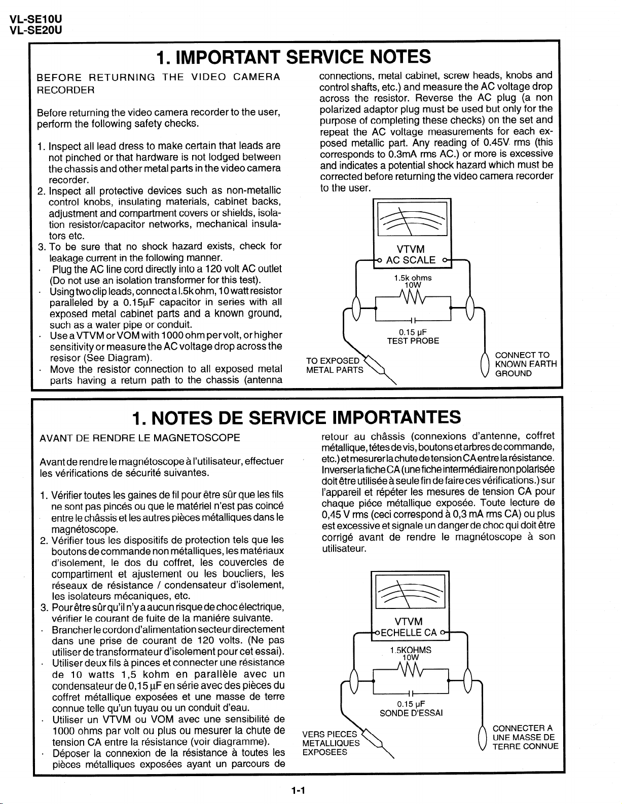
3. To be sure that no shock hazard exists, check for
leakage current in the following manner.
.
Plug the AC line cord directly into a 120 volt AC outlet
(Do not use an isolation transformer for this test).
. Using twoclip leads, connect a IZkohm, IO watt resistor
paralleled by a 0.1 !$F capacitor in series with all
exposed metal cabinet parts and a known ground,
such as a water pipe or conduit.
.
UseaVTVM orVOM with IOOOohm pervolt, or higher
sensitivity or measure the AC voltage drop across the
resisor (See Diagram).
.
Move the resistor connection to all exposed metal
parts having a return path to the chassis (antenna
connections, metal cabinet, screw heads, knobs and
control shafts, etc.) and measure the AC voltage drop
across the resistor. Reverse the AC plug (a non
polarized adaptor plug must be used but only for the
purpose of completing these checks) on the set and
repeat the AC voltage measurements for each exposed metallic part. Any reading of 0.45V rms (this
corresponds to 0.3mA rms AC.) or more is excessive
and indicates a potential shock hazard which must be
corrected before returning the video camera recorder
to the user.
B
VTVM
TO EXPOSED
METAL PARTS
LZBE )
< 0 AC SCALE 0 \
’ m5:o~ims
\
1. NOTES DE SERVICE IMPORTANTES
AVANT DE RENDRE LE MAGNETOSCOPE
Avant de rendre le magnetoscope a I’utilisateur, effectuer
les verifications de securite suivantes.
1. Verifier toutes les gaines de fil pour etre sur que les fils
ne sont pas pin& ou que le materiel n’est pas coin&
entre le chassis et les autres pieces metalliques dans le
magnetoscope.
2. Verifier tous les dispositifs de protection tels que les
boutons de commande non metalliques, les materiaux
d’isolement, le dos du coffret, les couvercles de
compartiment et ajustement ou les boucliers, les
reseaux de resistance / condensateur d’isolement,
les isolateurs mecaniques, etc.
3. Pour etre stir qu’il n’y a aucun risque de choc electrique,
verifier le courant de fuite de la maniere suivante.
.
Brancher le cordon d’alimentation secteur directement
dans une prise de courant de 120 volts. (Ne pas
utiliser de transformateur d’isolement pour cet essai).
. Utiliser deux fils a pinces et connecter une resistance
de 10 watts I,5 kohm en parallele avec un
condensateur de 0,15 PF en serie avec des pieces du
coffret metallique exposees et une masse de terre
connue telle qu’un tuyau ou un conduit d’eau.
.
Utiliser un VTVM ou VOM avec une sensibilite de
1000 ohms par volt ou plus ou mesurer la chute de
tension CA entre la resistance (voir diagramme).
.
Deposer la connexion de la resistance a toutes les
pieces metalliques exposees ayant un parcours de
retour au chassis (connexions d’antenne, coffret
metallique, t&es devis, boutons et arbres de commande,
etc.) et mesurer lachutede tension CAentre la resistance.
lnverser lafiche CA (unefiche intermediaire non polarisee
doit etre utilisee a seule fin de faire ces verifications.) sur
I’appareil et repeter les mesures de tension CA pour
chaque piece metallique exposee. Toute lecture de
0,45 V rms (ceci correspond a 0,3 mA rms CA) ou plus
est excessive et signale un danger de choc qui doit etre
corrige avant de rendre le magnetoscope a son
utilisateur.
VERS PIECES
ExposEE~~“”
METALLIQUES
l-l
Page 3

VL-SE1 OU
VL-SE2OU
WARNING :TO REDUCETHE RISK OF FIRE OR ELECTRIC SHOCK, DO NOT EXPOSE
THIS APPLIANCE TO WET LOCATIONS.
CAUTION
CAUTION: TO REDUCE THE RISK OF ELECTRIC
SHOCK. DO NOT REMOVE COVER. NO
USERSERVICEABLE PARTS INSIDE.
REFER SERVICING TO QUALIFIED SERVICE
PERSONNEL.
This symbol mark means following. Camcorder
For continued protection against fire haz-
ard, replace only with same type fuse.
(CP9Ol; 2A 72V, CP902; 2A 72V)
only
I
A I
This symbol warns the user of uninsulated
voltage within the unit that can cause dangerous electric shocks.
This symbol alerts the user that there are
important operating and maintenance instruc-
tions in the literature accompanying this unit.
1 CAUTION
This symbol mark means following.
For continued protection against fire haz-
ard, replace only with same type fuse.
(Fl; 1 .bA 25OVj
_ -
AC Adapter
only
//
ATTENTION: POUR REDUIRE LES RESQUES D’INCENDIE OU DE CHOC ELECTRIQUE,
NE PAS EXPOSER CET APPAREIL A LA PLUIE OU A L’HUMIDITE.
ATTENTION
Ce symbole signifie que l’on devra uti- Camcorder
liser un fusible de meme type (CP901; seulement
2A 72V, CP902; 2A 72V) pour assurer la
securite.
A
A
ATTENTION: AFIN DE REDUIRE LES RISQUES DE
CHOC ELECTRIQUE, NE PAS RETIRER LE
COUVERCLE, AUCUN ORGANE INTERNE
NE PEUT ETRE REPARE PAR
L’UTIUSATEUR, CONFIER L’APPAREIL A
UN DEPANNEUR QUALIFIE.
I
0
Ce symbole signale a I’utilisateur la presence
d’une tension non isolee a I’interieur de I’appareil
qui peut etre la cause de secousses electriques
dangereuses.
Ce symbole aver-tit I’utilisateur que des instructions importantes relatives a I’utilisation
et al’entretien se trouvent dans le manuel
accompagnant I’appareil.
ATTENTION
Ce symbole signifie que I’on devra uti- Adaptateur CA
liser un fusible de meme type (Fl; 1.5A,
250V) pour assurer la securite.
1-2
seulement
Page 4
VL-SE1 OU
VL-SE20U
\
.A CAUTION
BEFORE BAmERY DESTROY
NICKEL-CADMIUM BATTERY
The following program is available in the United States. Please consult local environmental
authorities concerning the availability of this or other programs in your area.
The RBRCTM Seal
SHARP participates in the RBRCTM* Nickel-Cadmium Battery Recycling Program in the United
States. The RBRCTM Seal on our battery pack contained in our product indicates that SHARP is
voluntarily participating in an industry program to collect and recycle these batteries. The RBRCTM
program provides you with a convenient alternative to placing spent Nickel-Cadmium battery packs into
the trash or municipal waste stream, which is illegal in some areas. At the end of their useful life, the
Nickel-Cadmium battery can be dropped off at the nearest collection center for recycling. For information
on the nearest collection center, call I-800-8-BATTERY or your local recycling center. If you are located
outside the United States, contact your local authorities for information concerning proper disposal and/
or recycling of this battery. SHARP’s involvement in this program is part of our commitment to protecting
our environment and conserving natural resources.
[Footnote] *RBRCTM is trademark of the Rechargeable Battery Recycling Corporation.
NICKEL-METAL HYDRIDE BATTERY
LlTHhJM or LITHIUM-ION BATTERY
SEALED LEAD BATTERY
Battery disposal
Contains the above (Rechargeable) Battery. must be recycled or disposed of properly.
Remove the Battery from the products and contact Federal or State Environmental Agencies for
information on recycling and disposal options.
13
I
Page 5
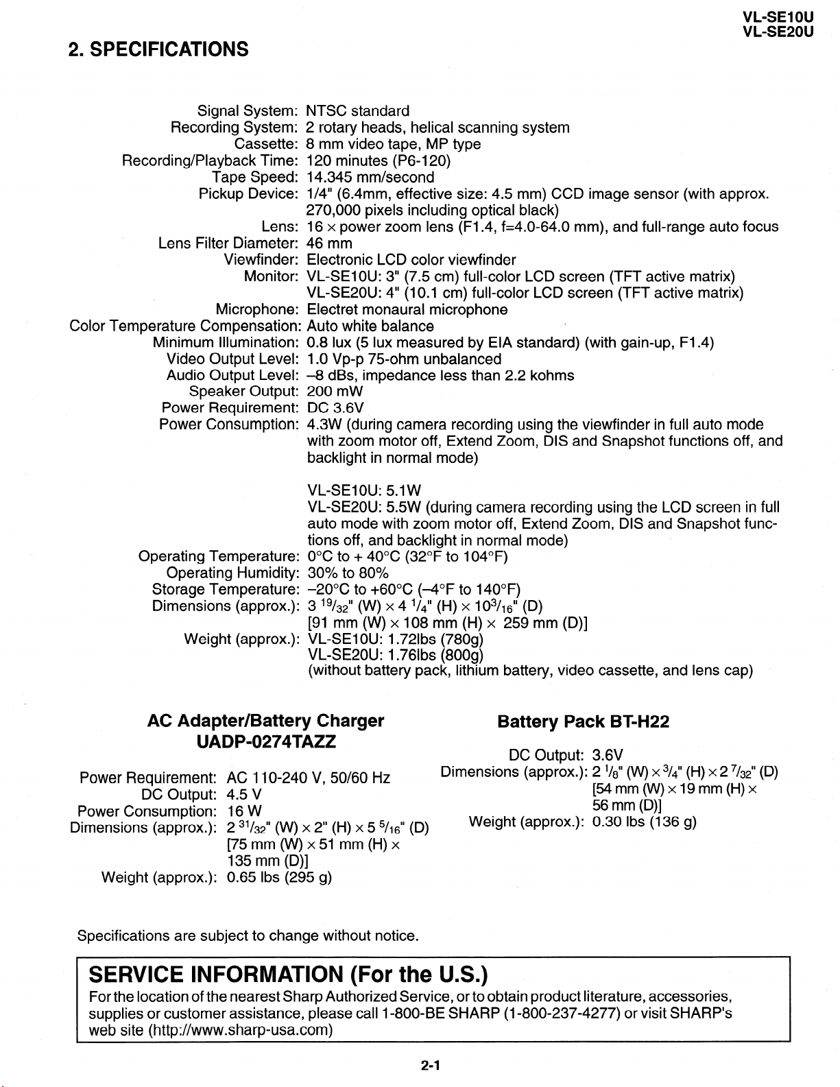
2. SPECIFICATIONS
Signal System: NTSC standard
Recording System:
Cassette:
Recording/Playback Time:
Tape Speed:
Pickup Device:
Lens:
Lens Filter Diameter: 46 mm
Viewfinder: Electronic LCD color viewfinder
Monitor:
Microphone:
Color Temperature Compensation:
Minimum Illumination:
Video Output Level:
Audio Output Level:
Speaker Output:
Power Requirement:
Power Consumption:
VL-SE1 OU
VL-SE20U
2 rotary heads, helical scanning system
8 mm video tape, MP type
120 minutes (P6-120)
14.345 mm/second
l/4” (6.4mm, effective size: 4.5 mm) CCD image sensor (with approx.
270,000 pixels including optical black)
16 x power zoom lens (Fl.4, f=4.0-64.0 mm), and full-range auto focus
VL-SEIOU: 3” (7.5 cm) full-color LCD screen (TFT active matrix)
VLSE20U: 4” (10.1 cm) full-color LCD screen (TFT active matrix)
Electret monaural microphone
: Auto white balance
0.8 lux (5 lux measured by EIA standard) (with gain-up, Fl.4)
1 .O Vp-p 75-ohm unbalanced
-8 dBs, impedance less than 2.2 kohms
200 mW
DC 3.6V
4.3W (during camera recording using the viewfinder in full auto mode
with zoom motor off, Extend Zoom, DIS and Snapshot functions off, and
backlight in normal mode)
VL-SEIOU: 5.lW
VLSE20U: 5.5W (during camera recording using the LCD screen in full
auto mode with zoom motor off, Extend Zoom, DIS and Snapshot functions off, and backlight in normal mode)
Operating Temperature:
Operating Humidity: 30% to 80%
Storage Temperature: -2OOC to +6O”C (-4°F to 140°F)
Dimensions (approx.): 3 ’ g/32” (W) x 4 1/4” (H) x 1 03/, 6” (D)
Weight (approx.):
0°C to + 40°C (32°F to 104°F)
[91 mm (W) x 108 mm (H) x 259 mm (D)]
VL-SE1 OU: 1.72lbs (780g)
VLSE20U: 1.76lbs (800g)
(without battery pack, lithium battery, video cassette, and lens cap)
AC Adapter/Battery Charger
UADP-0274TAZZ
Power Requirement: AC 1 IO-240 V, 50/60 Hz
DC Output: 4.5 V
Power Consumption: 16 W
Dimensions (approx.): 2 31/32” (W) x 2” (H) x 5 5/16” (D)
[75 mm (W) x 51 mm (H) x
135 mm (D)]
Weight (approx.): 0.65 Ibs (295 g)
Battery Pack BT-H22
DC Output: 3.6V
Dimensions (approx.): 2 l/a” o(v) x 3/4” (H) x 2 7/$ (D)
[54mm(W)xl9mm(H)x
56 mm (D)]
Weight (approx.): 0.30 Ibs (136 g)
Specifications are subject to change without notice.
SERVICE INFORMATION (For the U.S.)
For the location of the nearest Sharp Authorized Service, or to obtain product literature, accessories,
supplies or customer assistance, please call I-800,BE SHARP (I-800-237-4277) or visit SHARP’s
web site (http://www.sharp-usa.com)
2-1
Page 6
VL-SE1 OU
VL-SE20U
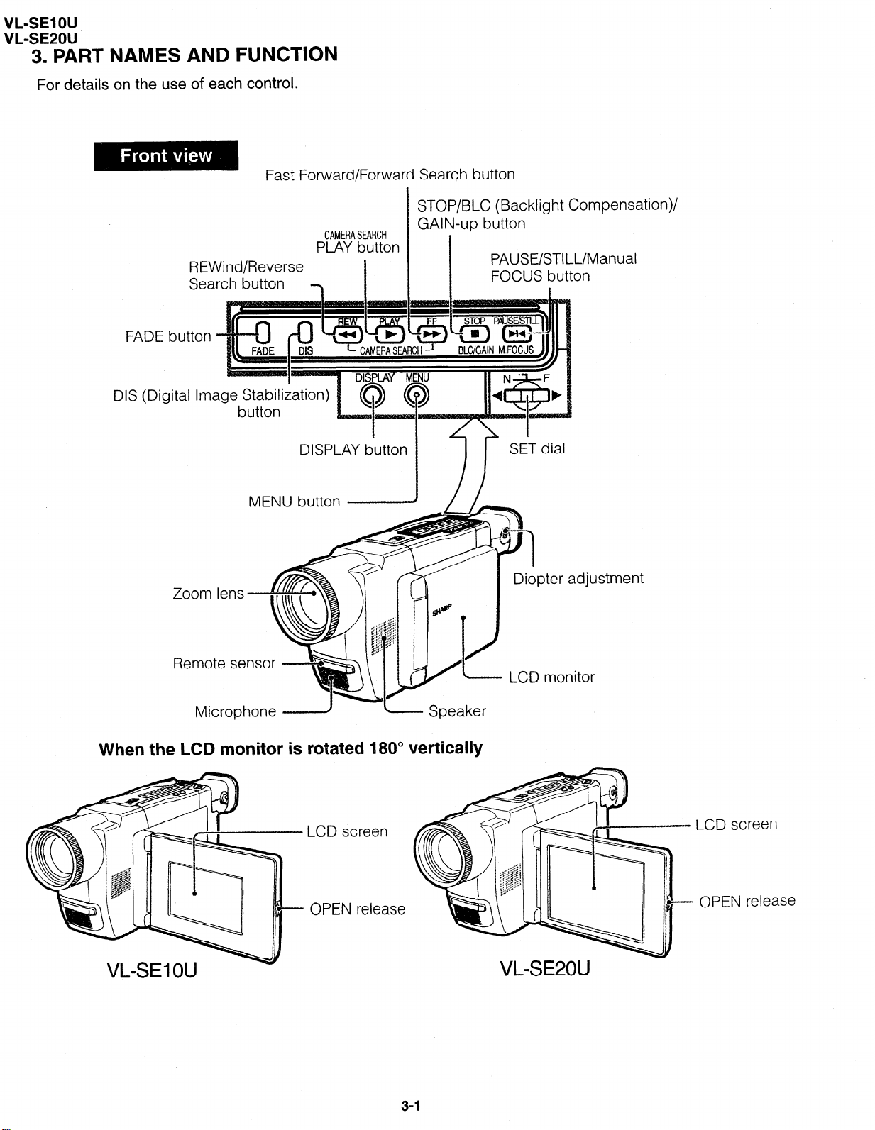
3. PART NAMES AND FUNCTION
For details on the use of each control.
Fast Forward/Forward Search button
REWind/Reverse
Search button
Zoom lens
CAMERASEARCH
PLAY button
I
DISPLAY button
STOP/BLC (Backlight Compensa
GAIN-up button
PAUSE/STILL/Manual
FOCUS button
i
tion)/
Remote se
Microphone _=.---J
L Speaker
When the LCD monitor is rotated 180” vertically
LCD screen
OPEN release
LCD screen
OPEN release
VL-SE20U
3-1
Page 7
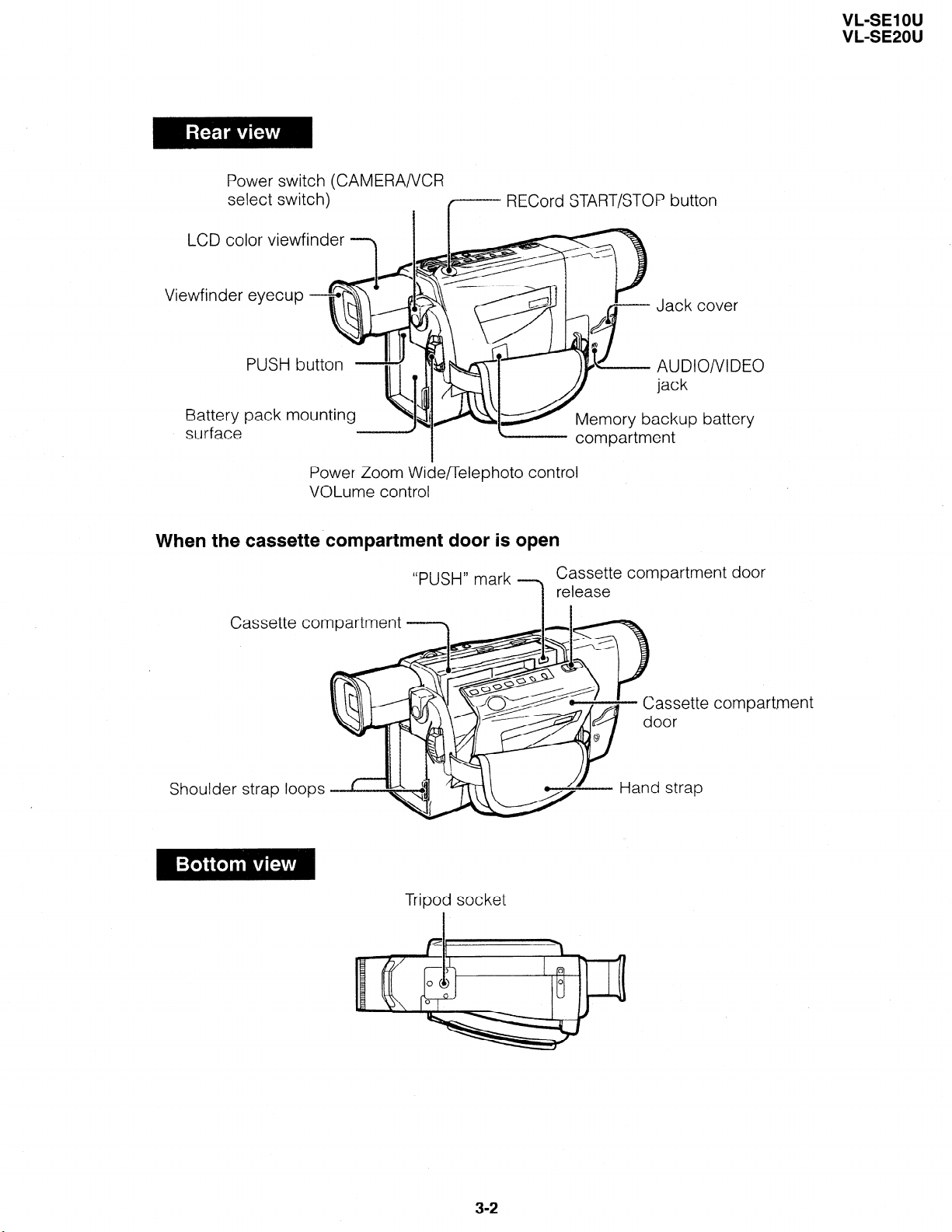
Power switch (CAMERA/VCR
select switch)
LCD color viewfinder
r--- RECord
VL-SE1 OU
VL-SE2OU
START/STOP button
Viewfinder evecup
J
pust
Battery pack
surface
Power Zoom Wide/Telephoto control
VOLume control
When the cassette compartment door is
“PUSH” mark
Cassette compartment --3
open
Cassette compartment door
release
1
Shoulder strap loops
Hand strap
Tripod socket
3-2
Page 8
VL-SE1 OU
VL-SE20U
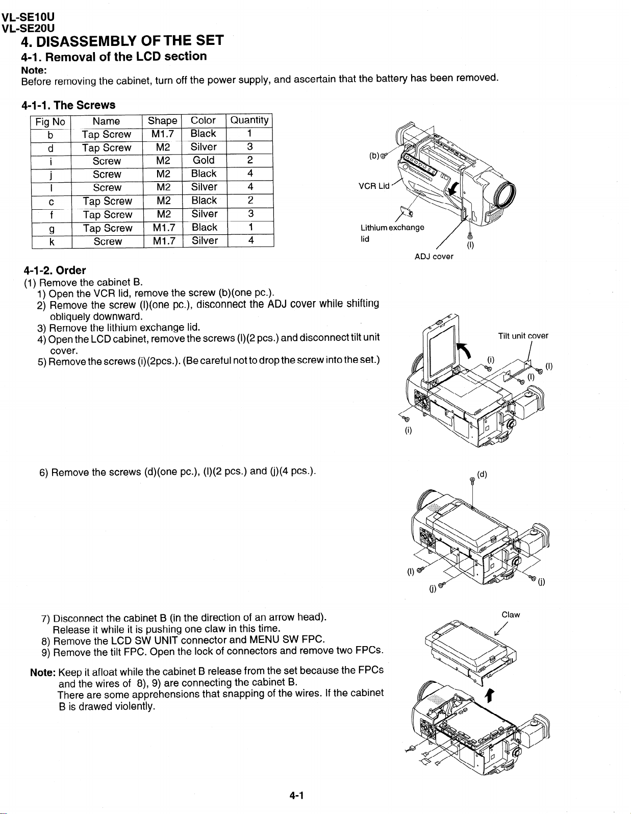
4. DISASSEMBLY OFTHE SET
4-1. Removal of the LCD section
Note:
Before removing the cabinet, turn off the power supply, and ascertain that the battery has been removed.
4-l-l. The Screws
Fig No
b
d
i
.
1
I
C
f
a
”
k
Name
Tap Screw
Tap Screw M2
Screw
Screw
Screw
Tap Screw M2
Tap Screw M2
Tap Screw
Screw
4-l-2. Order
(1) Remove the cabinet B.
1) Open the VCR lid, remove the screw (b)(one PC.).
2) Remove the screw (l)(one PC.), disconnect the ADJ cover while shifting
obliquely downward.
3) Remove the lithium exchange lid.
4) Open the LCD cabinet, remove the screws (I)(2 PCS.) and disconnect tilt unit
cover.
5) Remove the screws (i)(2pcs.). (Be careful not to drop the screw into the set.)
Shape Color Quantity
Ml .7
Black
1
Silver 3
M2
M2
M2
Gold
Black
Silver 4
Black
2
4
2
Silver 3
Ml .7
Ml .7
Black
Silver 4
1
lid
/
ADJ cover
(1)
6) Remove the screws (d)(one PC.), (I)(2 PCS.) and (j)(4 PCS.).
7) Disconnect the cabinet B (in the direction of an arrow head).
Release it while it is pushing one claw in this time.
8) Remove the LCD SW UNIT connector and MENU SW FPC.
9) Remove the tilt FPC. Open the lock of connectors and remove two FPCs.
Note: Keep it afloat while the cabinet B release from the set because the FPCs
and the wires of 8), 9) are connecting the cabinet B.
There are some apprehensions that snapping of the wires. If the cabinet
B is drawed violently.
Claw
4-1
Page 9
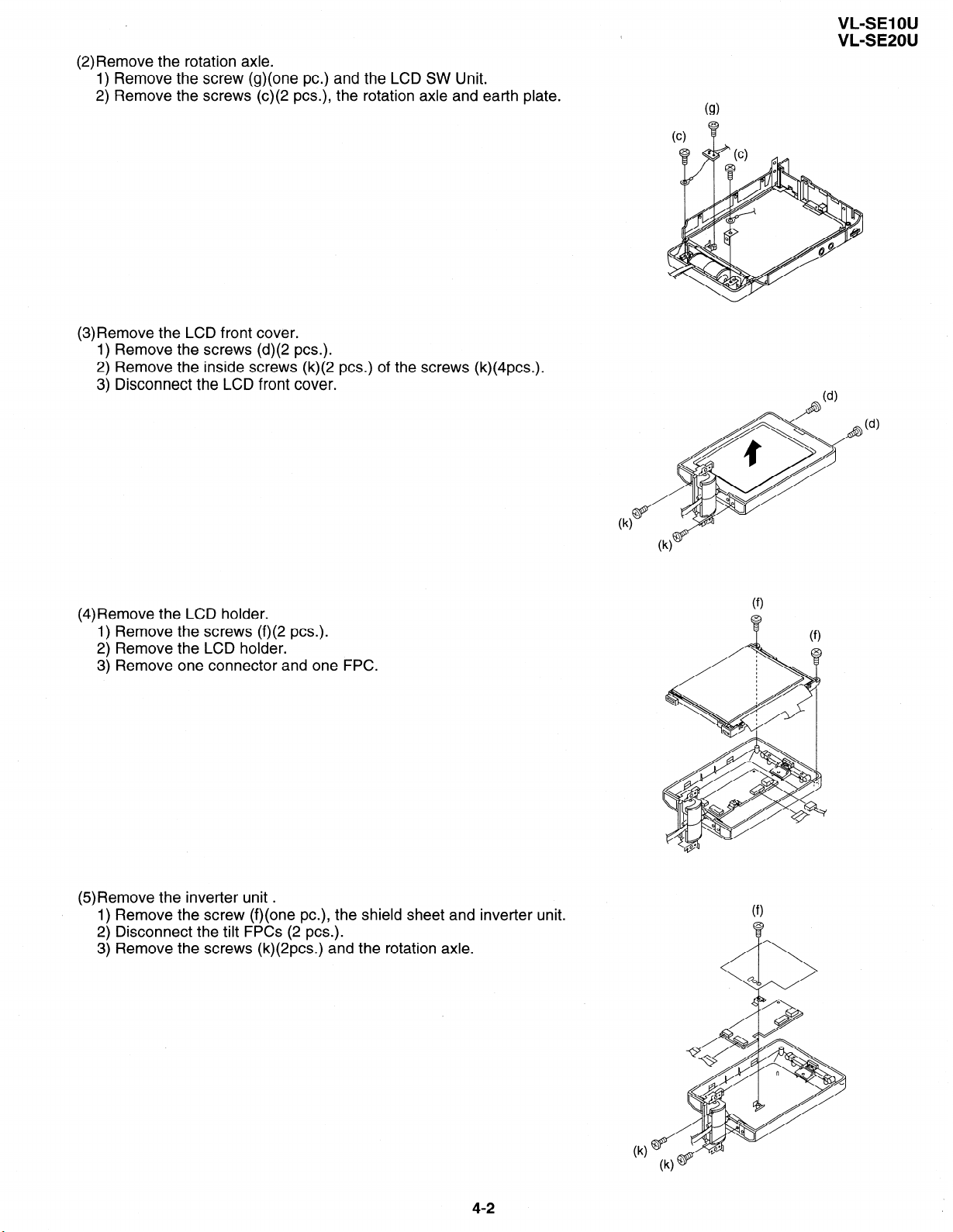
(2) Remove the rotation axle.
1) Remove the screw (g)(one PC.) and the LCD SW Unit.
2) Remove the screws (c)(2 PCS.), the rotation axle and earth plate.
(3)Remove the LCD front cover.
1) Remove the screws (d)(2 PCS.).
2) Remove the inside screws (k)(2 PCS.) of the screws (k)(4pcs.).
3) Disconnect the LCD front cover.
VL-SE1 OU
VL-SE20U
(4)Remove the LCD holder.
1) Remove the screws (f)(2 PCS.).
2) Remove the LCD holder.
3) Remove one connector and one FPC.
(5)Remove the inverter unit .
1) Remove the screw (f)(one PC.), the shield sheet and inverter unit.
2) Disconnect the tilt FPCs (2 PCS.).
3) Remove the screws (k)(2pcs.) and the rotation axle.
4-2
Page 10
VL-SE1 OU
VL-SE20U
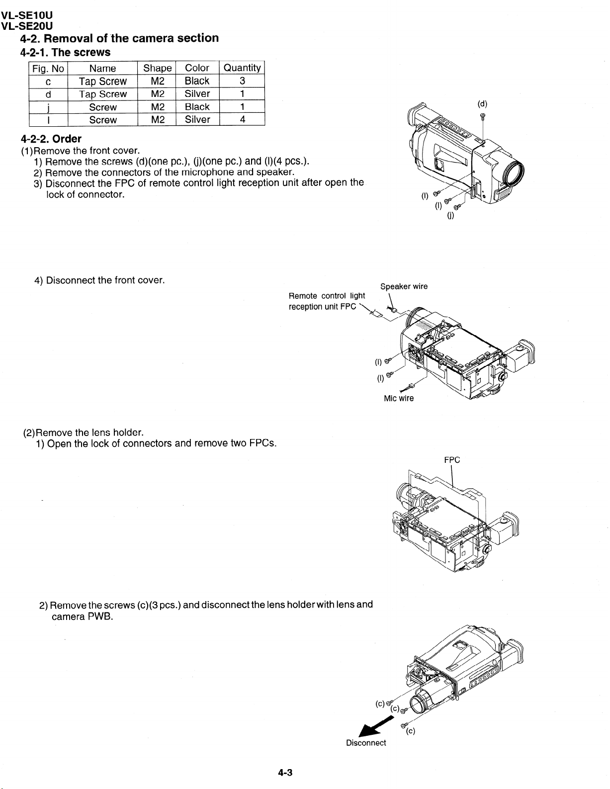
4-2. Removal of ‘the camera section
4-2-l. The screws
Fig. No
C
d
.
J
I
Name
Tap Screw M2
Tap Screw M2
Screw
Screw
4-2-2. Order
(l)Remove the front cover.
1) Remove the screws (d)(one PC.), (j)(one PC.) and (I)(4 PCS.).
2) Remove the connectors of the microphone and speaker.
3) Disconnect the FPC of remote control light reception unit after open the
lock of connector.
Shape Color Quantity
M2 Black
M2 Silver 4
Black
Silver
3
1
1
4) Disconnect the front cover.
(2)Remove the lens holder.
1) Open the lock of connectors and remove two FPCs.
Remote control light
reception unit FPC
Speaker wire
\
2) Remove the screws (c)(3 PCS.) and disconnect the lens holder with lens and
camera PWB.
Disconnect
4-3
Page 11
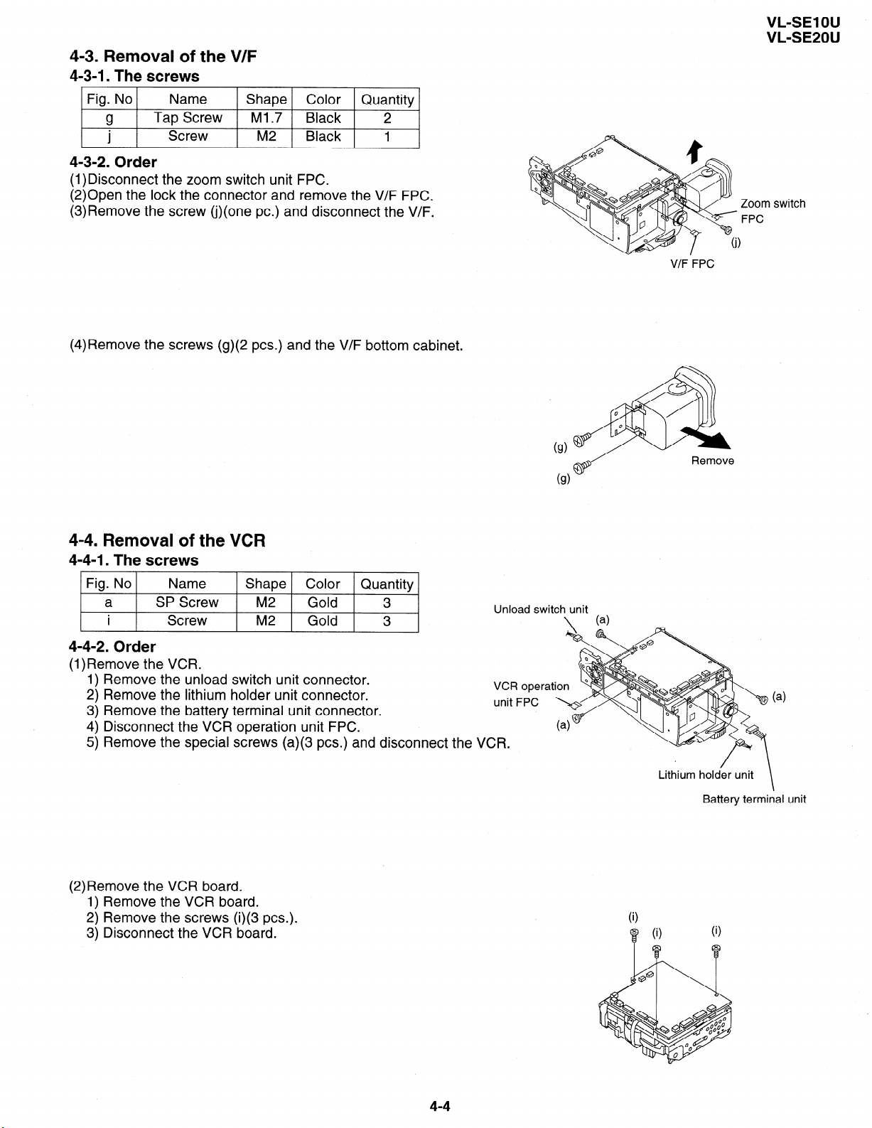
4-3. Removal of the V/F
4-3-l. The screws
Fig. No Name Shape Color Quantity
g
.
J
4-3-2. Order
(1)Disconnect the zoom switch unit FPC.
(2)Open the lock the connector and remove the V/F FPC.
(3)Remove the screw (j)(one PC.) and disconnect the V/F.
(4)Remove the screws (g)(2 PCS.) and the V/F bottom cabinet.
Tap Screw Ml .7 Black 2
Screw M2 Black 1
VL-SE1 OU
VL-SE20U
Zoom switch
FPC
V/F FPC
4-4. Removal of the VCR
4-4-l. The screws
Fig. No
a SP Screw M2 Gold
i
4-4-2. Order
(l)Remove the VCR.
1) Remove the unload switch unit connector.
2) Remove the lithium holder unit connector.
3) Remove the battery terminal unit connector.
4) Disconnect the VCR operation unit FPC.
5) Remove the special screws (a)(3 PCS.) and discon
Name Shape Color Quantity
Screw
M2
Gold 3
3
nect the VCR.
Unload switch unit
VCR operat
unit FPC
\
Lithium
Remove
( >
holder unit
\
Battery terminal unit
a
(2)Remove the VCR board.
1) Remove the VCR board.
2) Remove the screws (i)(3 PCS.).
3) Disconnect the VCR board.
4-4
i
0
i
0
i
0
Page 12
VL-SE1 OU
VL-SE201’
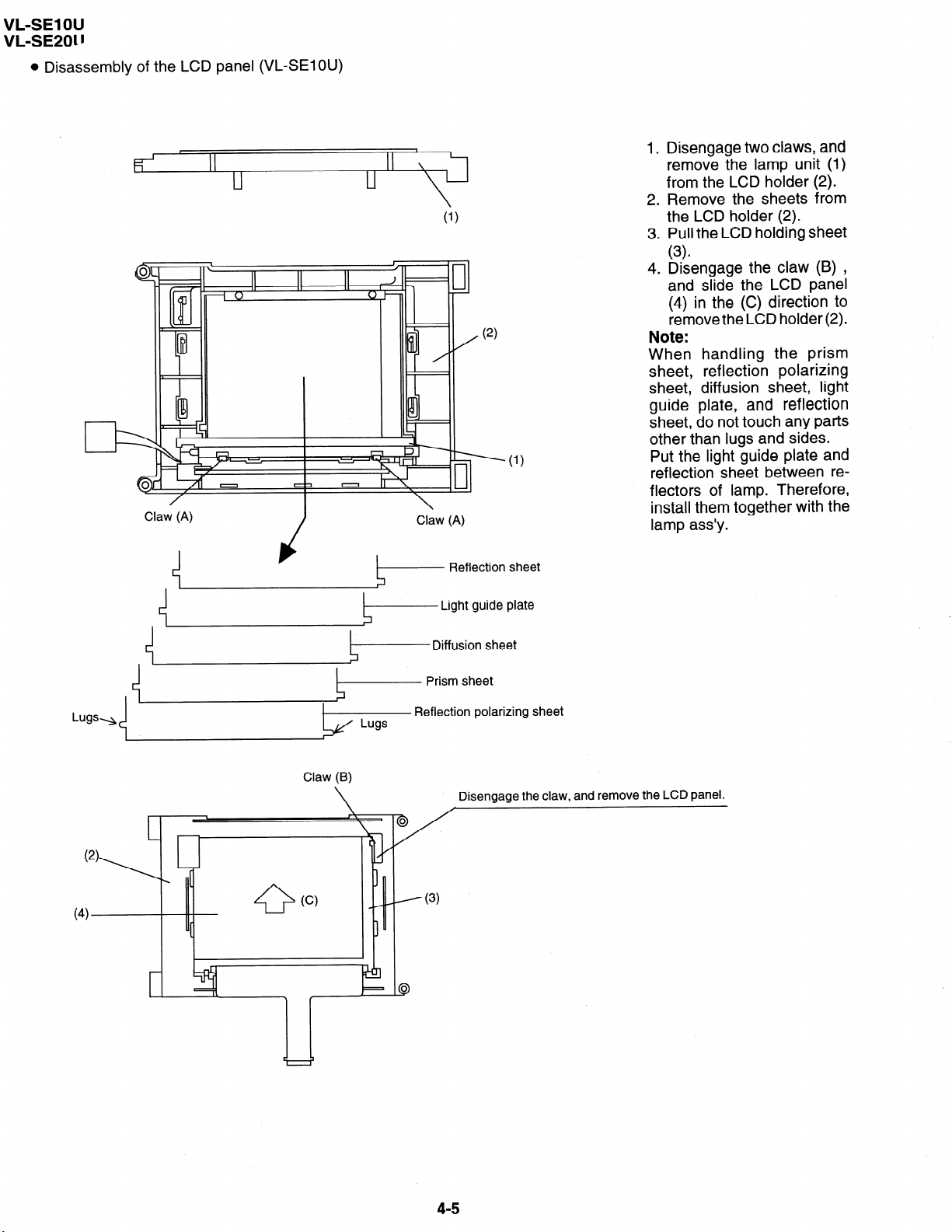
l Disassembly of the LCD panel (VL-SElOU)
Claw (A)
Claw (A)
(2)
1. Disengage two claws, and
remove the lamp unit (1)
from the LCD holder (2).
2. Remove the sheets from
the LCD holder (2).
3. Pull the LCD holding sheet
(3)
4. Disengage the claw (9) ,
and slide the LCD panel
(4) in the (C) direction to
remove the LCD holder (2).
Note:
When handling the prism
sheet, reflection polarizing
sheet, diffusion sheet, light
guide plate, and reflection
sheet, do not touch any parts
other than lugs and sides.
Put the light guide plate and
reflection sheet between re-
flectors of lamp. Therefore,
install them together with the
lamp ass’y.
(4)
(2)
Reflection sheet
Light guide plate
Diffusion sheet
&------ Prism sheet
Reflection polarizing sheet
Claw (B)
Disengage the claw, and remove the LCD panel.
\
0
(c)
[
4-5
Page 13
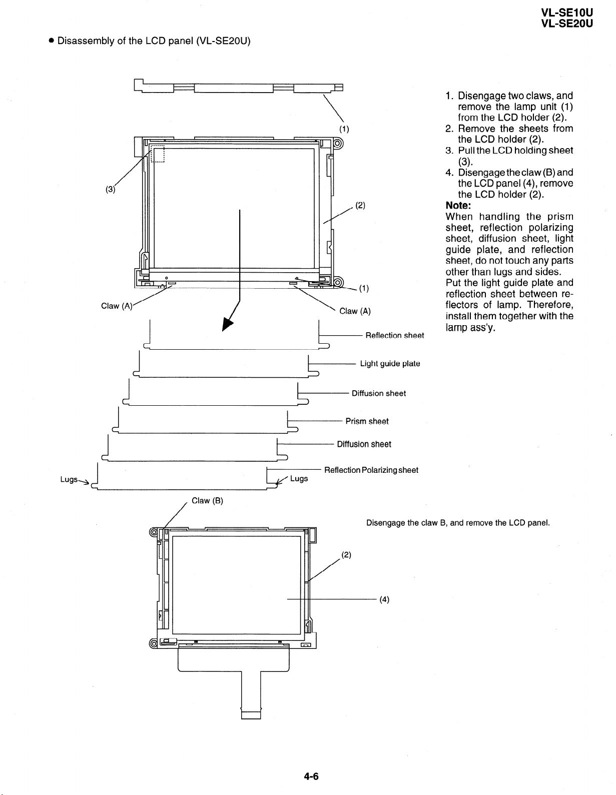
l Disassembly of the LCD panel (VL-SEZOU)
VL-SE1 OU
VL-SE2OU
I 4
I 1
Claw (A)
Reflection sheet
Light guide plate
1.
Disengage two claws, and
remove the lamp unit (1)
from the LCD holder (2).
2.
Remove the sheets from
the LCD holder (2).
3.
Pull the LCD holding sheet
(3)
4.
Disengage the claw (B) and
the LCD panel (4), remove
the LCD holder (2).
Note:
When handling the prism
sheet, reflection polarizing
sheet, diffusion sheet, light
guide plate, and reflection
sheet, do not touch any parts
other than lugs and sides.
Put the light guide plate and
reflection sheet between reflectors of lamp. Therefore,
install them together with the
lamp ass’y.
/
Claw (B)
}p
Diffusion sheet
Prism sheet
Diffusion sheet
Reflection Polarizing sheet
Disengage
the claw B, and
(2)
- (4)
remove the LCD
panel.
4-6
Page 14
VL-SE1 OU
VL-SE20U
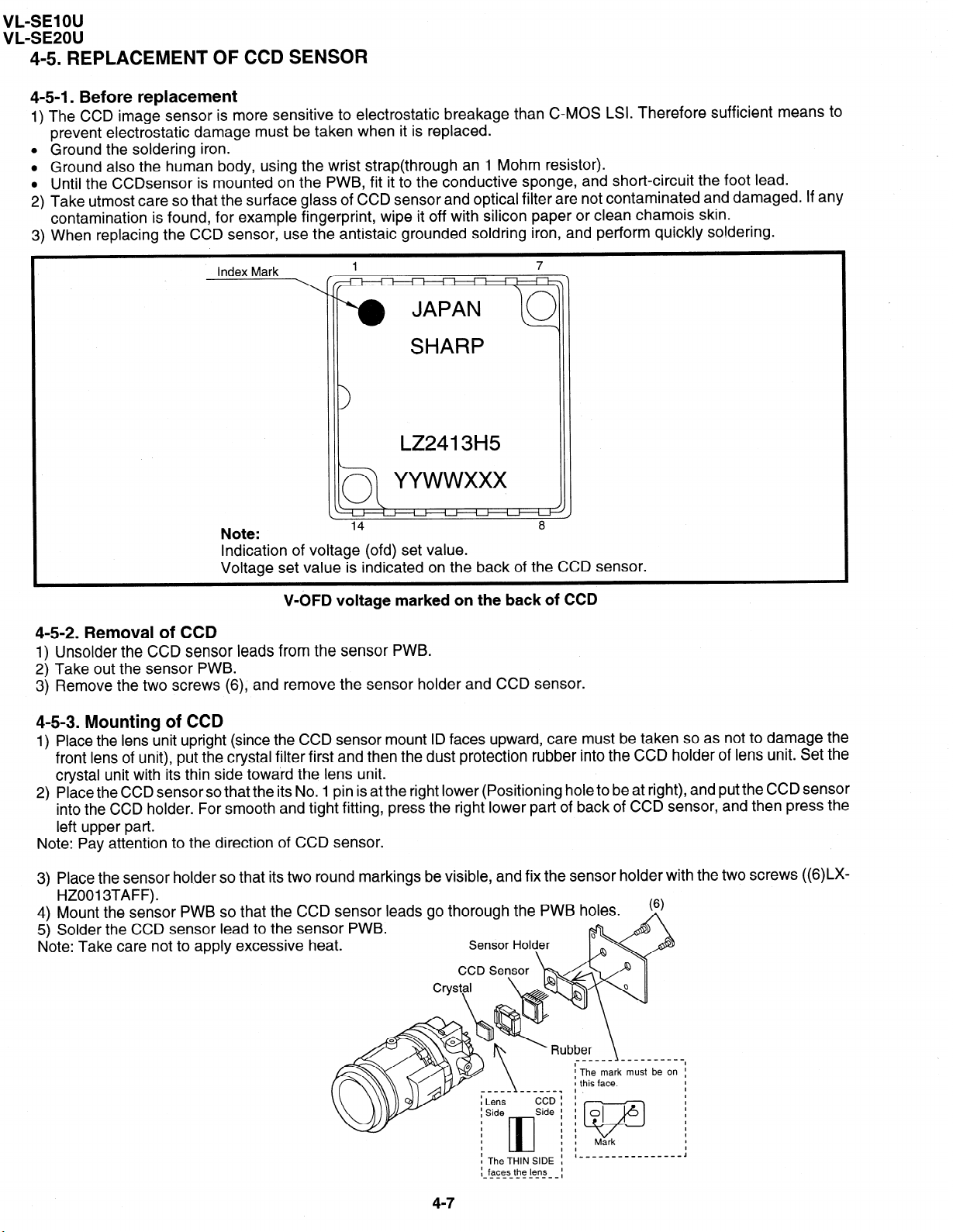
4-5. REPLACEMENT OF CCD SENSOR
4-5-l. Before replacement
The CCD image sensor is more sensitive to electrostatic breakage than CMOS LSI. Therefi
prevent electrostatic damage must be taken when it is replaced.
Ground the soldering iron.
Ground also the human body, using the wrist strap(through an 1 Mohm resistor).
Until the CCDsensor is mounted on the PWB, fit it to the conductive sponge, and short-circuit the foot lead.
Take utmost care so that the surface glass of CCD sensor and optical filter are not contaminated and damaged. If any
contamination is found, for example fingerprint, wipe it off with silicon paper or clean chamois skin.
When replacing the CCD sensor, use the antistaic grounded soldring iron, and perform quickly so!dering.
ore sufficient means to
Index Mark
Note:
I
Indication of voltage (ofd) set value.
1 7
14 8
Voltage set value is indicated on the back of the CCD sensor.
V-6FD voltage marked on the back of CCD
4-5-2. Removal of CCD
1) Unsolder the CCD sensor leads from the sensor PWB.
2) Take out the sensor PWB.
3) Remove the two screws (6), and remove the sensor holder and CCD sensor.
4-5-3. Mounting of CCD
1) Place the lens unit upright (since the CCD sensor mount ID faces upward, care must be taken so as not to damage the
front lens of unit), put the crystal filter first and then the dust protection rubber into the CCD holder of lens unit. Set the
crystal unit with its thin side toward the lens unit.
2) Place the CCD sensor so that the its No. 1 pin is at the right lower (Positioning hole to be at right), and put the CCD sensor
into the CCD holder. For smooth and tight fitting, press the right lower part of back of CCD sensor, and then press the
left upper part.
Note: Pay attention to the direction of CCD sensor.
3) Place the sensor holder so that its two round markings be visible, and fix the sensor holder with
HZ001 3TAFF).
4) Mount the sensor PWB so that the CCD sensor leads go thorough the PWB holes.
5) Solder the CCD sensor lead to the sensor PWB.
Note: Take care not to apply excessive heat.
Sensor Holder
: TheTH,NS,DE ; I,,- __________--- J
: faces the lens
____________
\
Jbt 3er
\
__-___----
___--- .
The mark
this face.
0
I
v
Mark
must be on :
:
the two screws
I
1
I
I
I
I
((wo
47
I
Page 15
VL-SE1 OU
VL-SE20U
4-6. INlTIAL SETTING OF E*PROM IC
4-6-l. E*PROM data alterable ways
Set the switch of main body to VCR, and use the remote control (RRMCG0033TASA) for adjustment to turn on the
1)
adjustment mode.
VCR adjustment address setting.
2)
3)
4)
5)
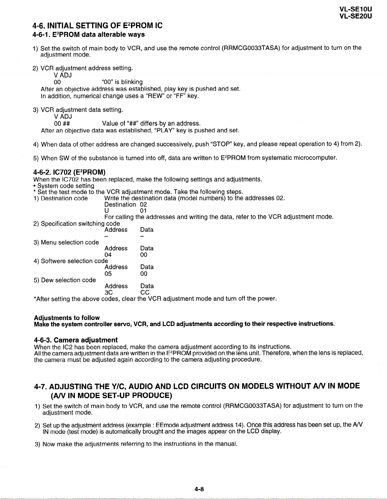
4-6-2. IC702 (E*PROM)
When the IC702 has been replaced, make the following settings and adjustments.
l System code setting
* Set the test mode to the VCR adjustment mode. Take the following steps.
1) Destination code
5) Dew selection code
*After setting the above codes, clear the VCR adjustment mode and turn off the power.
V ADJ
00
After an objective address was established, play key is pushed and set.
In addition, numerical change uses a “REW” or “FF” key.
VCR adjustment data setting.
V ADJ
00 ##
After an objective data was established, “PLAY” key is pushed and set.
When data of other address are changed successively, push “STOP” key, and please repeat operation to 4) from 2).
When SW of the substance is turned into off, data are written to E*PROM from systematic microcomputer.
Specification switching code
Menu selection code
Softwere selection code
“00” is blinking
Value of “#I#” differs by an address.
Write the destination data (model numbers) to the addresses 02.
Destination 02
U
For calling the addresses and writing the data, refer to the VCR adjustment mode.
Address
- -
Address Data
04 00
Address Data
05
Address Data
3c cc
01
Data
00
Adjustments to follow
Make the system controller
servo, VCR, and LCD adj ustments
according to their respective
instructions.
4-6-3. Camera adjustment
When the IC2 has been replaced, make the camera adjustment according to its instructions.
All the camera adjustment data are written in the E*PROM provided on the lens unit. Therefore, when the lens is replaced,
the camera must be adjusted again according to the camera adjusting procedure.
4-7. ADJUSTING THE Y/C, AUDIO AND LCD CIRCUITS ON MODELS WITHOUT A/V IN MODE
(A/V IN MODE SET-UP PRODUCE)
Set the switch of main body to VCR, and use the remote control (RRMCGOO33TASA) for adjustment to turn on the
1)
adjustment mode.
Set up the adjustment address (example : EEmode adjustment address 14). Once this address has been set up, the A/V
2)
IN mode (test mode) is automatically brought and the images appear on the LCD display.
Now make the adjustments referring to the instruotions in the manual.
3)
4-a
Page 16
VL-SE1 OU
VL-SE20U
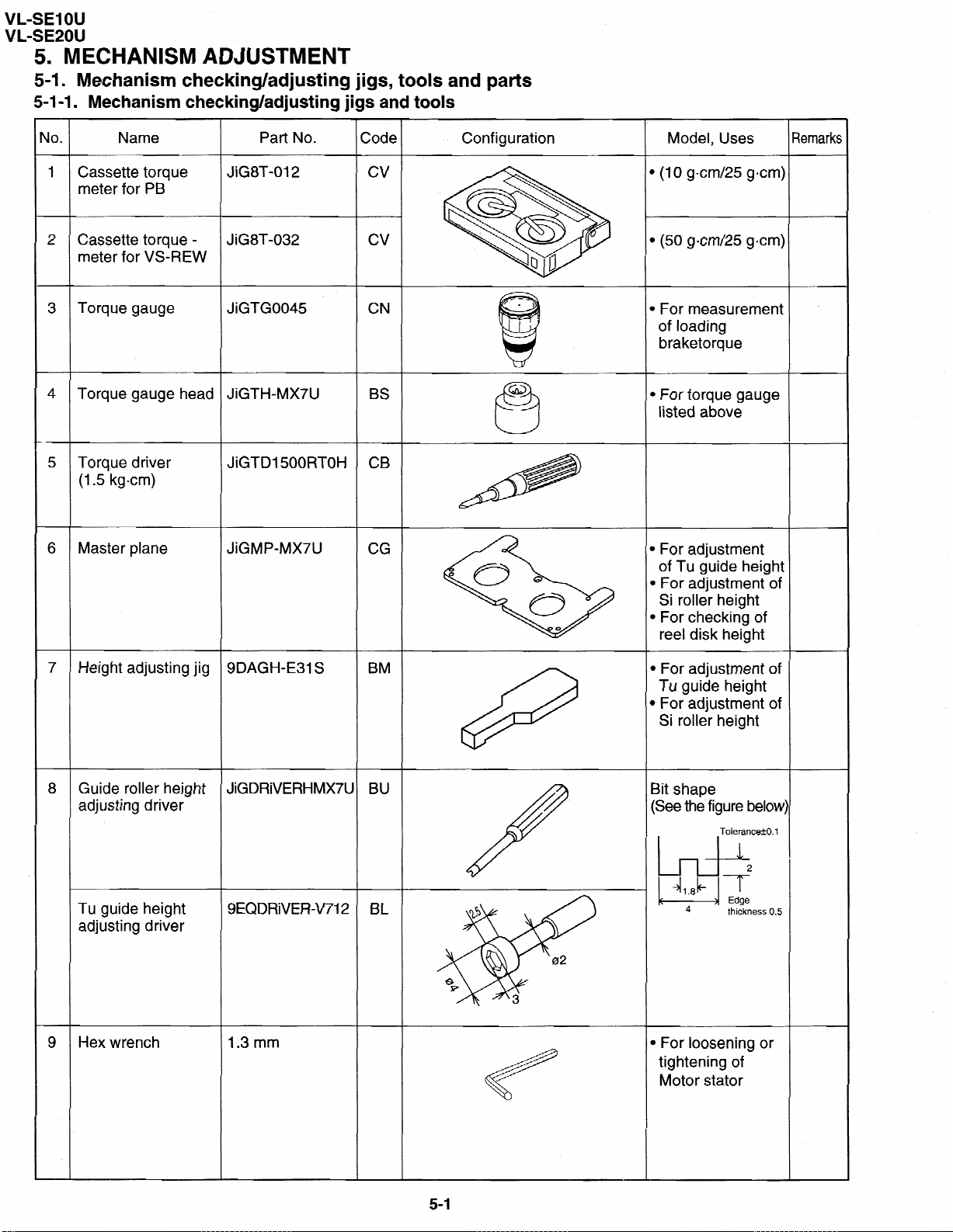
5. MECHANISM ADJUSTMENT
5-1. Mechanism
5-l-l. Mechanism checking/adjusting jigs and tools
.
40
1
Name
Cassette torque
meter for PB
checking/adjusting jigs, tools and parts
Part No.
JiG8T-012
Zode
cv
Configuration
Model, Uses
1
(10 gem/25 gem)
Iemarks
2 Cassette torque -
meter for VS-REW
3 Torque gauge
4 Torque
Torque driver
5
(1.5 kgcm)
6 Master plane
7 Height adjusting jig
gauge head
cv JiG8T-032
JiGTG0045 ’
JiGTH-MX7U
JiGMP-MX7U CG
SDAGH-E31 S BM
CN
BS
CB JiGTDl500RTOH
Gika
4
1 (50 gem/25 gem)
) For measurement
of loading
braketorque
b For torque gauge
listed above
b For adjustment
of Tu guide height
B For adjustment of
Si roller height
m For checking of
reel disk height
. For adjustment of
Tu guide height
l
For adjustment of
Si roller height
8 Guide roller height
adjusting driver
Tu guide height
adjusting driver
Hex wrench
9
JiGDRiVERHMX7L
SEQDRiVER-V712 BL
1.3 mm
BU
8
17
:
5-l
/
15
Bit shape
(See the figure
02
3
l For loosening or
tightening of
Motor stator
below
Tolerance&O. 1
thickness 0.5
Page 17
.
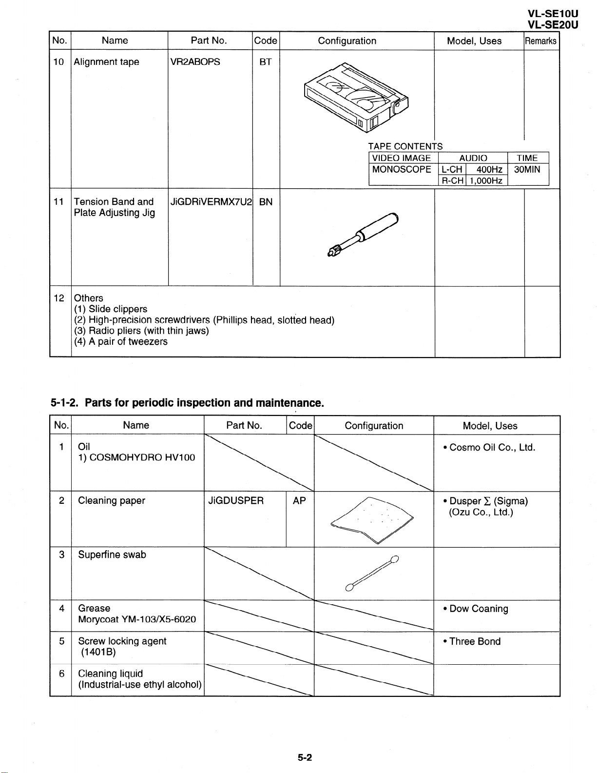
No
Name Part No. Code
10 Alignment tape VWABOPS BT
Configuration Model, Uses
VL-SE1 OU
VL-SE2OU
Remarks
\
11 Tension Band and JiGDRiVERMX7U2 BN
Plate Adjusting Jig
12 Others
(1) Slide clippers
(2) High-precision screwdrivers (Phillips head, slotted head)
(3) Radio pliers (with thin jaws)
(4) A pair of tweezers
5-l-2. Parts for periodic inspection and maintenance.
.
IO
Name Part No. Code
,
Ql0
TAPE CONTENTS
VIDEO IMAGE
MONOSCOPE L-CH 400Hz 30MIN
&
AUDIO
R-CH 1,OOOHz
3 9
Configuration Model, Uses
TIME
1 Oil
l Cosmo Oil Co., Ltd.
1) COSMOHYDRO HWOO
2 Cleaning paper JiGDUSPER AP
l Dusper C (Sigma)
(Ozu Co., Ltd.)
3 Superfine swab
4 Grease
l Dow Coaning
Morycoat YM-103/X5-6020
5 Screw locking agent l Three Bond
(14OlB)
6 Cleaning liquid
(Industrial-use ethyl alcohol)
5-2
Page 18
VL-SEIOU
VL-SE20U
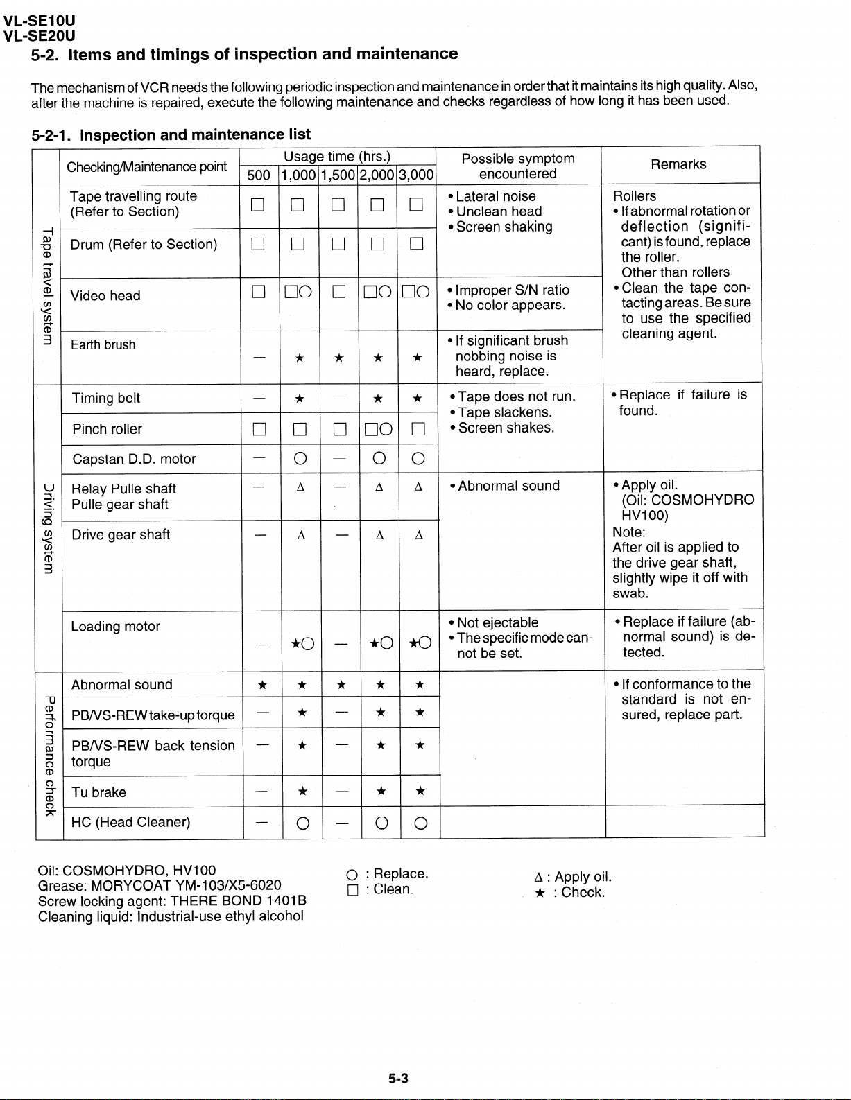
5-2. Items and timings of inspection and maintenance
The mechanism of VCR needs the following periodic inspection and maintenance in order that it maintains its high quality. Also,
after the machine is repaired, execute the following maintenance and checks regardless of how long it has been used.
5-2-l. Inspection and maintenance list
Checking/Maintenance point -
Tape travelling route
(Refer to Section)
A+~
g Drum (Refer to Section)
CD
z.
z5
- Video head
2
v,
5.
3
Earth brush
Usage time (hrs.)
500 1,000 1,500 2,000 3,000
q 0 [7 0 0 :~;;~a,noh~~d
q 0 0 0 0
0 00 j’-J 00 c]O *Improper S/N ratio
* * * *
Possible symptom
encountered
Remarks
Rollers
l If abnormal rotation or
l Screen shaking deflection (signifi-
cant) is found, replace
the roller.
Other than rollers
@Clean the tape con-
l No color appears.
tatting areas Be sure
to use the specified
l If significant brush
cleaning agent.
nobbing noise is
heard, replace.
Timing belt
Pinch roller
Capstan D.D. motor
v Relay Pulle shaft
0 cl III 00 0
* - * *
- 0 - 0 0
A - A A
Z: Pulle gear shaft
cz
Drive gear shaft
z
v,
A - A A
z
3
Loading motor
- *o -
Abnormal sound
2
z PBNS-REWtake-uptorque - * - * *
0
‘T
* * * * *
*o a
z PB/VS-REW back tension - * - * *
Z torque
CD
g Tu brake
* - * *
g
x HC (Head Cleaner)
0 0 0
*Tape does not run.
l Tape slackens.
l Screen shakes.
l Abnormal sound
l Not ejectable
0 The specific mode can-
not be set.
*Replace if failure is
found.
l Apply oil.
(Oil: COSMOHYDRO
HVI 00)
Note:
After oil is applied to
the drive gear shaft,
slightly wipe it off with
swab.
l Replace if failure (ab-
normal sound) is de-
tected.
0 If conformance to the
standard is not ensured, replace part.
Oil: COSMOHYDRO, HVI 00
Grease: MORYCOAT YM-103/X5-6020
Screw locking agent: THERE BOND 14018
Cleaning liquid: industrial-use ethyl alcohol
0 : Replace.
0 : Clean.
I
53
A : Apply oil.
j, : Check.
Page 19
VL-SE1 OU
VL-SE2OU
5-2-2. Notes and cautions
(1) Any cut washers, once removed for parts replacement or for other reason, must be replaced with new ones.
(2) The mechanism of this VCR does not involve any volume adjustment. If the specified range is not satisfied, either
cleaning or replacing the parts is required.
(3) Oils
a) Be sure to use the specified oils (different viscosity may cause troubles).
b) For the bearings, be sure to use oil that is free form dust and other foreign substances. (Dust or foreign substance
contained in the oil may cause wear or seizure of the bearings.)
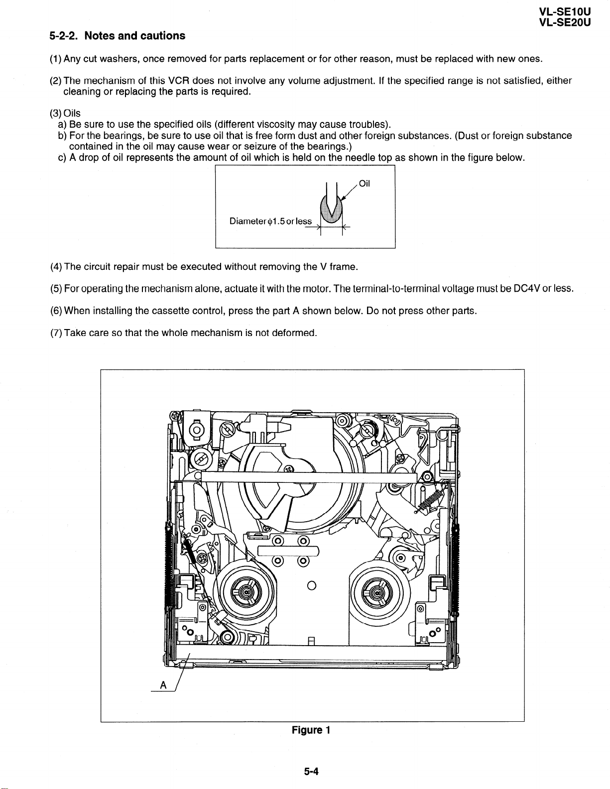
c) A drop of oil represents the amount of oil which is held on the needle top as shown in the figure below.
Oil
(4) The circuit repair must be executed without removing the V frame.
(5) For operating the mechanism alone, actuate it with the motor. The terminal-to-terminal voltage must be DC4V or less.
(6) When installing the cassette control, press the part A shown below. Do not press other parts.
(7)Take care so that the whole mechanism is not deformed.
Figure 1
5-4
Page 20
VL-SElOU
VL-SE20U
5-3. Mechanism checks and adjustments
The description given below relates to the general field services, but does not relate to the adjustment and replacement
that require high level equipments, jigs, and technical skills.
In order to maintain the initial characteristics of the machine, it is necessary to execute the maintenance and check and
to prevent damage to tapes and other parts. For adjustments which need jigs, be sure to use the jigs.
Notes and cautions
(1) For mechanism checks and adjustments, be sure to use the AC adapter as the power supply.
(2) For running the tape, be sure to install the cassette control ass’y in advance. (If the cassette control ass’y is to be
removed subsequently after its installation.)
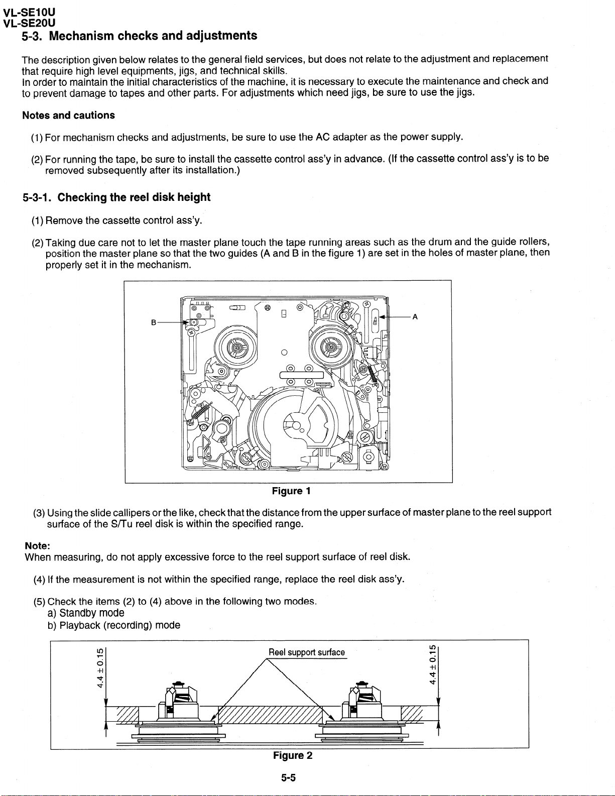
5-3-l. Checking the reel disk height
(1) Remove the cassette control ass’y.
(2) Taking due care not to let the master plane touch the tape running areas such as the drum and the guide rollers,
position the master plane so that the two guides (A and B in the figure 1) are set in the holes of master plane, then
properly set it in the mechanism.
B-
Figure 1
(3) Using the slide callipers or the like, check that the distance from the upper surface of master plane to the reel support
surface of the S/Tu reel disk is within the specified range.
Note:
When measuring, do not apply excessive force to the reel support surface of reel disk.
(4) If the measurement is not within the specified range, replace the reel disk ass’y.
(5) Check the items (2) to (4) above in the following two modes.
a) Standby mode
b) Playback (recording) mode
A
Reel support surface
Figure 2
5-5
Page 21
VL-SE1 OU
VL-SE20U
5-3-2. Checking the take-up torque for playback (recording)
(1) Set the torque cassette (8T-012) in position, and check in the SP-mode recording mode (tape recorded in SP mode)
that the torque at the tape taking-up side is within the standard range.
Standard of take-up torque for SP-mode recording (playback)
9 + 3 gem with ripples less than 4 gem
(If the torque ripples appear, read the center value of torque between the ripples.)
5-3-3. Checking and adjusting the back tension torque for playback (recording)
(1) Checking
1) Set the torque cassette (81-012) in position, and check in the SP-mode recording mode (tape recorded in SP mode)
that the torque at the tape supply side is within the standard range.
Standard of back tension torque for SP-mode recording (playback):
8 & 2 gem with ripples of less than 2 gem
(Torque ripple must be within 8 + 2 gem)
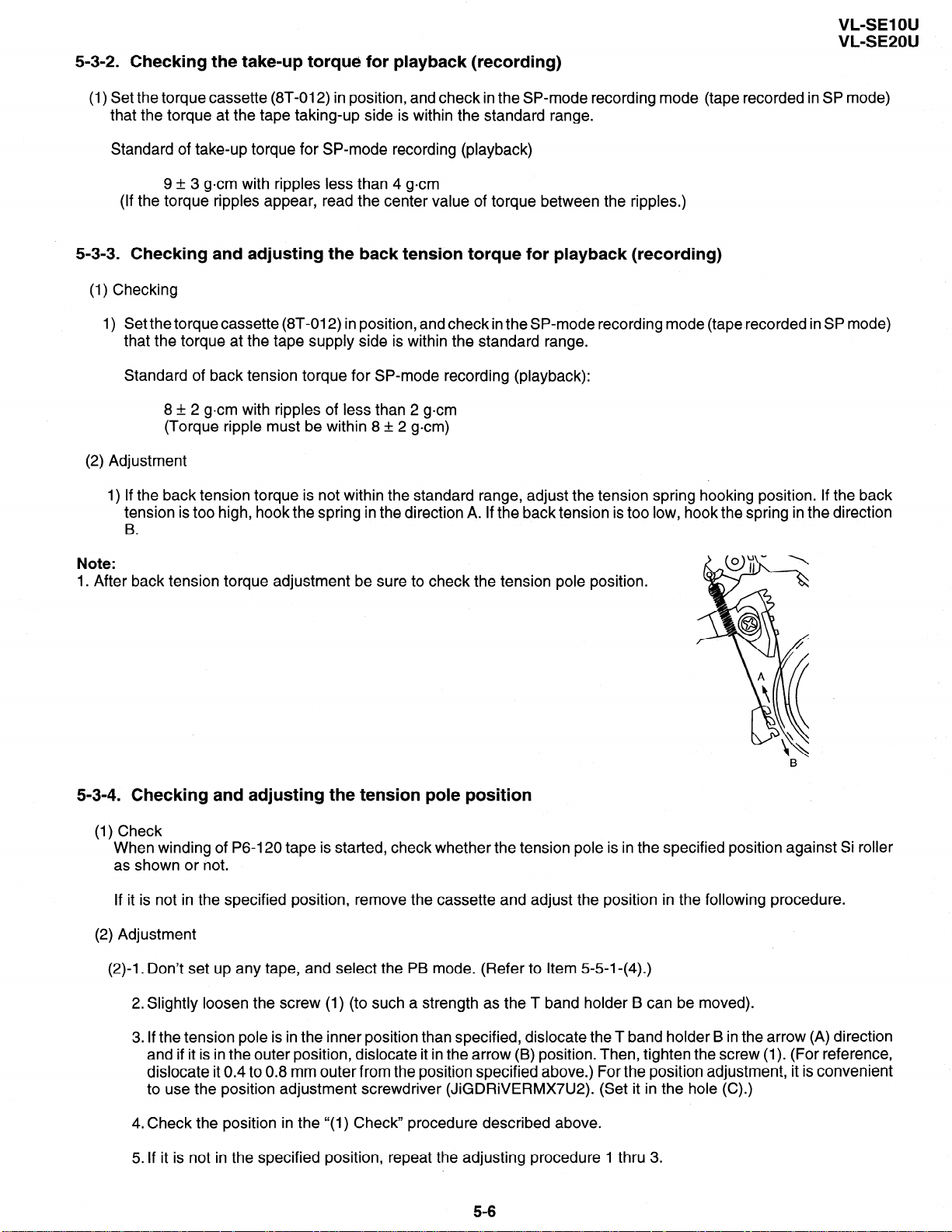
(2) Adjustment
1) If the back tension torque is not within the standard range, adjust the tension spring hooking position. If the back
tension is too high, hook the spring in the direction A. If the back tension is too low, hook the spring in the direction
.
B
Note:
1. After back tension
torque adjustment be sure to check
the tension pole position.
5-3-4. Checking and adjusting the tension pole position
(1) Check
When winding of P6-120 tape is started, check whether the tension pole is in the specified position against Si roller
as shown or not.
If it is not in the specified position, remove the cassette and adjust the position in the following procedure.
(2) Adjustment
(2)-l. Don’t set up any tape, and select the PB mode. (Refer to Item 5-5-l-(4).)
2.Slightly loosen the screw (1) (to such a strength as the T band holder B can be moved).
3. If the tension pole is in the inner position than specified, dislocate the T band holder B in the arrow (A) direction
and if it is in the outer position, dislocate it in the arrow (B) position. Then, tighten the screw (1). (For reference,
dislocate it 0.4 to 0.8 mm outer from the position specified above.) For the position adjustment, it is convenient
to use the position adjustment screwdriver (JiGDRiVERMX7U2). (Set it in the hole (C).)
4. Check the position in the “(1) Check’ procedure described above.
5. If it is not in the specified position, repeat the adjusting procedure 1 thru 3.
5-6
Page 22
VL-SE1 OU
VL-SE20U
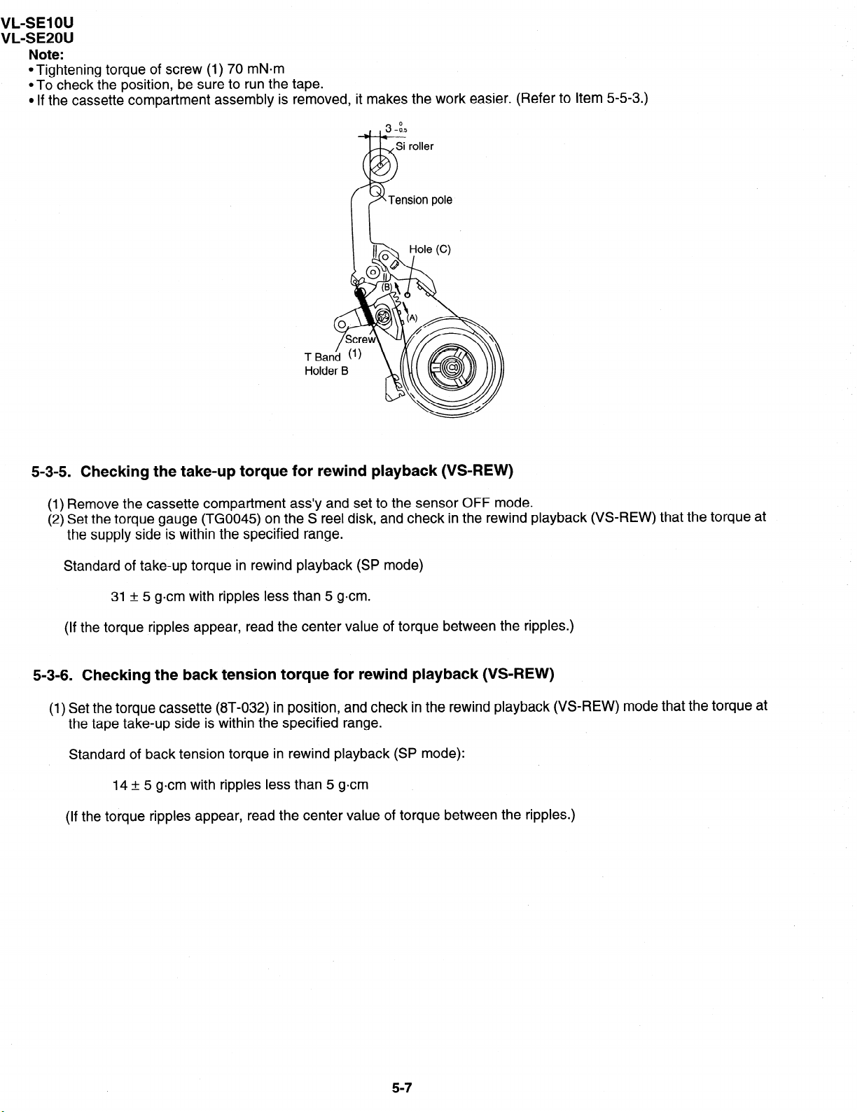
Note:
l Tightening torque of screw (1) 70 mN=m
*To check the position, be sure to run the tape.
l If the cassette compartment assembly is removed, it makes the work easier. (Refer to Item 5-5-3.)
5-3-5. Checking the take-up torque for rewind playback (VS-REW)
(1) Remove the cassette compartment ass’y and set to the sensor OFF mode.
(2) Set the torque gauge (TGO045) on the S reel disk, and check in the rewind playback (VS-REW) that the torque at
the supply side is within the specified range.
Standard of take-up torque in rewind playback (SP mode)
31 + 5 gem with ripples less than 5 gem.
(If the torque ripples appear, read the center value of torque between the ripples.)
5-3-6. Checking the back tension torque for rewind playback (VS-REW)
(1) Set the torque cassette (8T-032) in position, and check in the rewind playback (VS-REW) mode that the torque at
the tape take-up side is within the specified range.
Standard of back tension torque in rewind playback (SP mode):
14 + 5 gem with ripples less than 5 gem
(If the torque ripples appear, read the center value of torque between the ripples.)
5-7
Page 23
5-4. ADJUSTMENT OF MECHANISM TAPE TRAVEL SYSTEM
Sup tilted pole
I
Tu tilted pole A
Reel
Tu GR
VL-SE1 OU
VL-SE20U
Tu guide
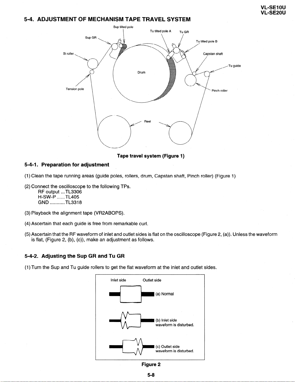
Tape travel system (Figure 1)
5-4-l. Preparation for
adjustment
(1) Clean the tape running areas (guide poles, rollers, drum, Capstan shaft, Pinch roller) (Figure 1)
(2) Connect the oscilloscope to the following TPs.
RF output . ..TL3306
H-SW-P . . . . ..TL405
. . . . . . . . . . . TL3318
GND
(3) Playback the alignment tape (VR2ABOPS).
(4) Ascertain that each guide is free from remarkable curl.
(5) Ascertain that the RF waveform of inlet and outlet sides is flat on the oscilloscope (Figure 2, (a)). Unless the waveform
is flat, (Figure 2, (b), (c)), make an adjustment as follows.
5-4-2. Adjusting the Sup GR and Tu GR
(1) Turn the Sup and Tu guide rollers to get the flat waveform at the inlet and outlet sides.
Inlet side
q-b (a) Normal
Outlet side
Figure 2
5-8
Page 24
VL-SE1 OU
VL-SE20U
5-4-3. Adjusting the Si roller height
After replacement of Si roller preset and adjust the Si roller height.
(1) Si roller height presetting
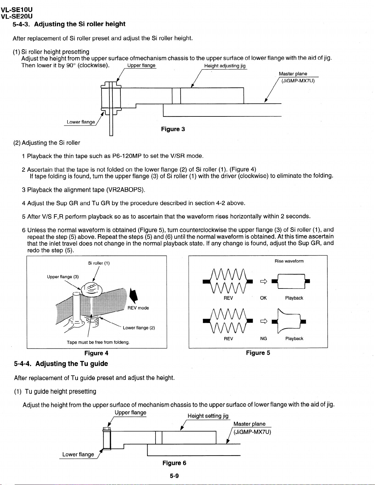
Adjust the height from the upper surface ofmechanism chassis to the upper surface of lower flange with the aid of jig.
Then lower it by 90° (clockwise).
(2) Adjusting the Si roller
1 Playback the thin tape such as P6-120MP to set the V/SR mode.
2 Ascertain that the tape is not folded on the lower flange (2) of Si roller (1). (Figure 4)
If tape folding is found, turn the upper flange (3) of Si roller (1) with the driver (clockwise) to eliminate the folding.
Upper flange
I
Figure 3
Height adjusting jig
Master plane
, /“““““”
3 Playback the alignment tape (VR2ABOPS).
4 Adjust the Sup GR and Tu GR by the procedure described in section 4-2 above.
5 After V/S F,R perform playback so as to ascertain that the waveform rises horizontally within 2 seconds.
6 Unless the normal waveform is obtained (Figure 5), turn counterclockwise the upper flange (3) of Si roller (I), and
repeat the step (5) above. Repeat the steps (5) and (6)‘until the normal waveform is obtained. At this time ascertain
that the inlet travel does not change in the normal playback state. If any change is found, adjust the Sup GR, and
redo the step (5).
OK
NG
Rise waveform
Playback
Playback
Upper flange (3)
Tape must be free from foldeng.
Si roller (1)
Figure 4
REV
REV
Figure 5
5-4-4. Adjusting the Tu guide
After replacement of Tu guide preset and adjust the height.
(1) Tu guide height presetting
Adjust the height from the upper surface of mechanism chassis to the upper surface of lower flange with the aid of jig.
Upper flange
i-
/ Height.setting jig Master p,ane
(JiGMP-MX7U)
I
Lower flange
Figure 6
I
59
Page 25
VL-SE1 OU
VL-SE20U
(2) Adjusting the Tu guide
1 Playback the Tu guide adjustment cassette (or the No.7 guide adjustment cassette for E30).
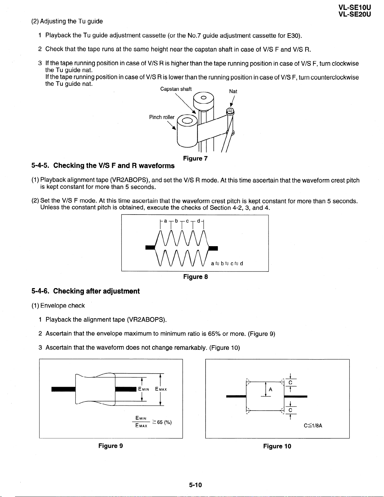
2 Check that the tape runs at the same height near the capstan shaft in case of V/S F and V/S R.
If the tape running position in case of V/S R is higher than the tape running position in case of V/S F, turn clockwise
3
the Tu guide nat.
If the tape running position in case of V/S R is lower than the running position in case of V/S F, turn counterclockwise
the Tu guide nat.
t
III 1 //
-
Figure 7
5-4-5. Checking the V/S F and R waveforms
(1) Playback alignment tape (VR2ABOPS), and set the V/S R mode. At this time ascertain that the waveform crest pitch
is kept constant for more than 5 seconds.
(2) Set the V/S F mode. At this time ascertain that the waveform crest pitch is kept constant for more than 5 seconds.
Unless the constant pitch is obtained, execute the checks of Section 4-2, 3, and 4.
t”T”T”T”1
Figure 8
5-4-6. Checking after adjustment
(1) Envelope check
1 Playback the alignment tape (VR2ABOPS).
2 Ascertain that the envelope maximum to minimum ratio is 65% or more. (Figure 9)
3 Ascertain that the waveform does not change remarkably. (Figure 10)
- EMIN EMAX
Figure 9
I
EMIN
- 265 (%)
EMAX
-d
-f-
C'lI8A
Figure 10
5-10
Page 26
VL-SE1 OU
VL-SE20U
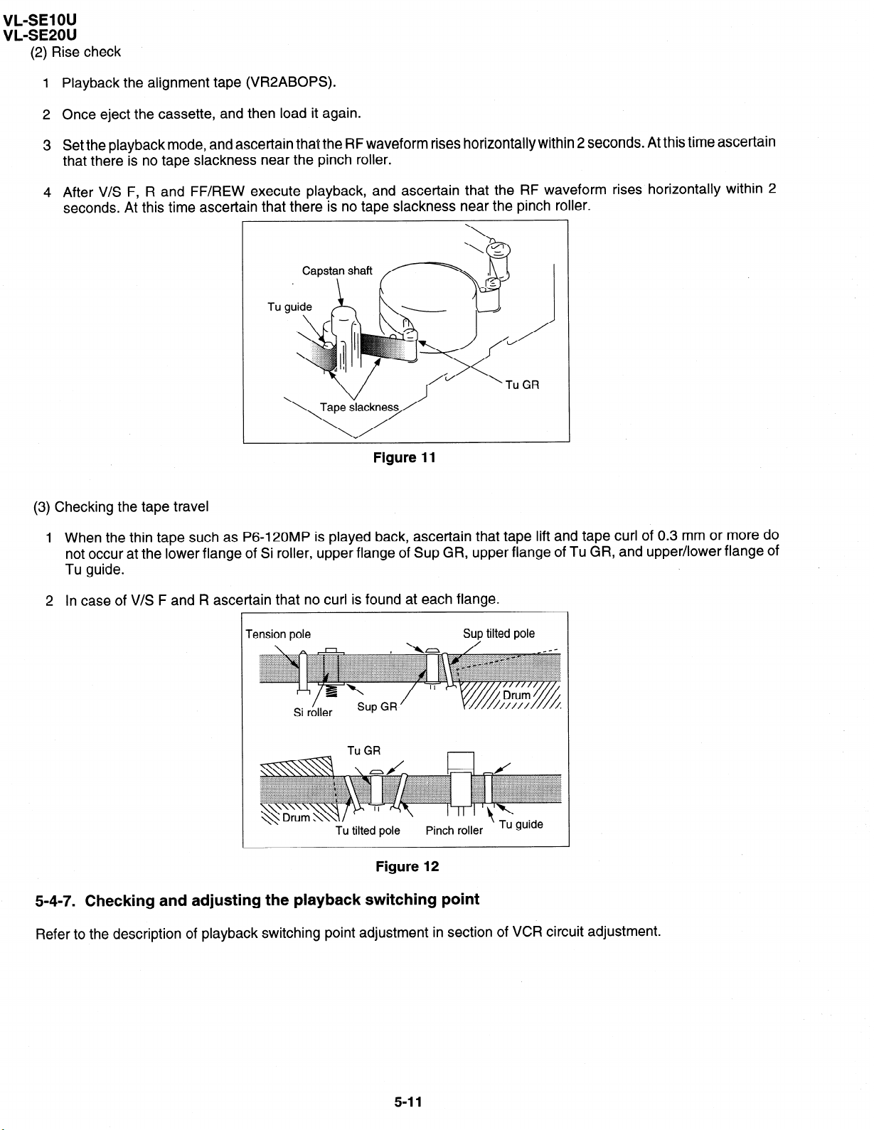
(2) Rise check
1
Playback the alignment tape (VR2ABOPS).
2 Once eject the cassette, and then load it again.
3
Set the playback mode, and ascertain that the RF waveform rises horizontally within 2 seconds. At this time ascertain
that there is no tape slackness near the pinch roller.
4 After V/S F, R and FF/REW execute playback, and ascertain that the RF waveform rises horizontally within 2
seconds. At this time ascertain that there is no tape slackness near the pinch roller.
Tu
Figure 11
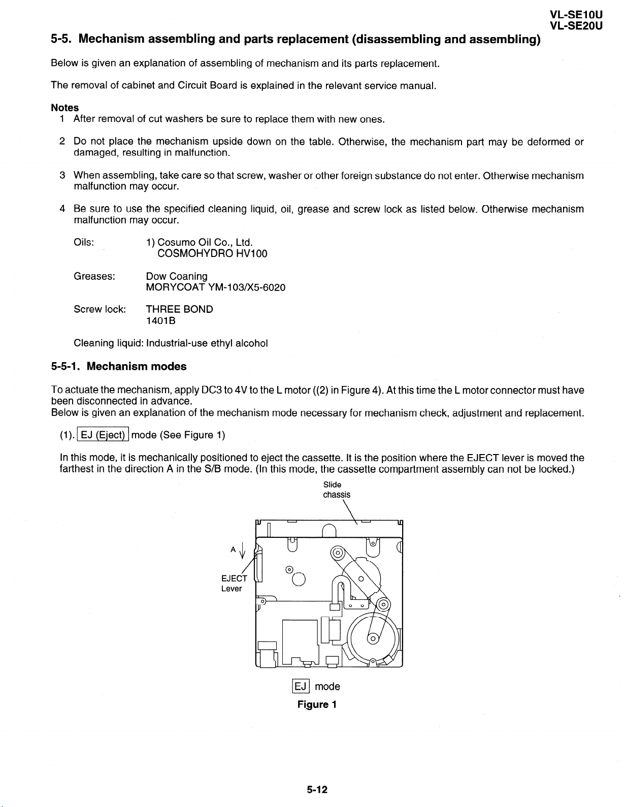
(3) Checking the tape travel
1
When the thin tape such as P6-120MP is played back, ascertain that tape lift and tape curl of 0.3 mm or more do
not occur at the lower flange of Si roller, upper flange of Sup GR, upper flange of Tu GR, and upper/lower flange of
Tu guide.
2
In case of V/S F and R ascertain that no curl is found at each flange.
Tension pole Sup tilted pole
Tu GR
Figure 12
5-4-7. Checking and adjusting the playback switching point
Refer to the description of playback switching point adjustment in section of VCR circuit adjustment.
5-I 1
Page 27
5-5. Mechanism assembling and parts replacement (disassembling and assembling)
Below is given an explanation of assembling of mechanism and its parts replacement.
The removal of cabinet and Circuit Board is explained in the relevant service manual.
Notes
After removal of cut washers be sure to replace them with new ones.
Do not place the mechanism upside down on the table. Otherwise, the mechanism part may be deformed or
damaged, resulting in malfunction.
When assembling, take care so that screw, washer or other foreign substance do not enter. Otherwise mechanism
malfunction may occur.
Be sure to use the specified cleaning liquid, oil, grease and screw lock as listed below. Otherwise mechanism
malfunction may occur.
Oils: 1) Cosumo Oil Co., Ltd.
COSMOHYDRO HVI 00
VL-SE1 OU
VL-SE20U
Greases:
Screw lock:
Cleaning liquid: industrial-use ethyl alcohol
Dow Coaning
MORYCOAT YM-103/X5-6020
THREE BOND
1401B
5-5-1. Mechanism modes
To actuate the mechanism, apply DC3 to 4V to the L motor ((2) in Figure 4). At this time the L motor connector must have
been disconnected in advance.
Below is given an explanation of the mechanism mode necessary for mechanism check, adjustment and replacement.
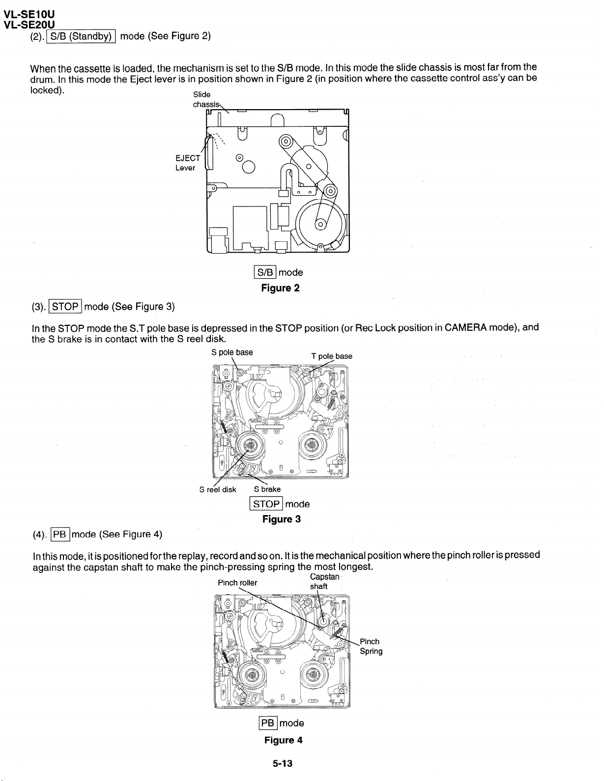
(1). -1 mode (See Figure 1)
In this mode, it is mechanically positioned to eject the cassette. It is the position where the EJECT lever is moved the
farthest in the direction A in the S/B mode. (In this mode, the cassette compartment assembly can not be locked.)
Slide
chassis
EJECT
EJ mode
cl
Figure 1
5-12
Page 28
VL-SE1 OU
VL-SE20U
(Z).S/B(Standby) mode (See Figure 2)
When the cassette is loaded, the mechanism is set to the S/B mode. In this mode the slide chassis is most far from the
drum. In this mode the Eject lever is in position shown in Figure 2 (in position where the cassette control ass’y can be
locked).
EJECT
Lever
Slide
chassis,
S/B mode
I
Figure 2
(3). m] mode (See Figure 3)
In the STOP mode the S.T pole base is depressed in the STOP position (or Ret Lock position in CAMERA mode), and
the S brake is in contact with the S reel disk.
S re’el disk
(4). pimode (See Figure 4)
In this mode, it is positioned for the replay,
against the capstan shaft to make the pi
record and so on. It is the mechanical position where the pinch roller is
rich-pressing spring the most longest.
Pinch roller
S brake
STOP mode
Figure 3
presse
Capstan.
s!aft
d
PB mode
El
Figure 4
5-13
Pinch
Spring
Page 29
VL-SE1 OU
VL&2OU
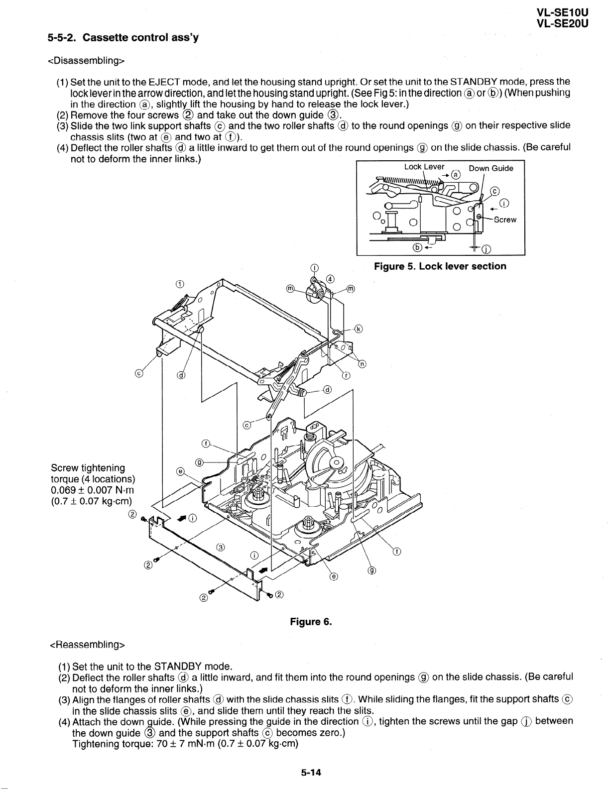
5-5-2. Cassette control ass)/
<Disassembling>
(1) Set the unit to the EJECT mode, and let the housing stand upright. Or set the unit to the STANDBY mode, press the
lock lever in the arrow direction, and let the housing stand upright. (See Fig 5: in the direction @ or @) (When pushing
in the direction @, slightly lift the housing by hand to release the lock lever.)
(2) Remove the four screws @ and take out the down guide @.
(3) Slide the two link support shafts @ and the two roller shafts @ to the round openings @ on their respective slide
chassis slits (two at @ and two at 0).
(4) Deflect the roller shafts @ a little inward to get them out of the round openings @ on the slide chassis. (Be careful
not to deform the inner links.)
Lock Lever
.
Figure 5. Lock lever section
Down Guide
Screw tightening
torque (4 locations)
0.069 + 0.007 Nom
(0.7 & 0.07 kgcm)
<Reassembling>
d
c)
0
Figure 6.
(I) Set the unit to the STANDBY mode.
(2) Deflect the roller shafts @ a little inward, and fit them into the round openings @ on the slide chassis. (Be careful
not to deform the inner links.)
(3) Align the flanges of roller shafts @ with the slide chassis slits 0. While sliding the flanges, fit the support shafts @
in the slide chassis slits @, and slide them until they reach the slits.
(4) Attach the down
the down guide 3 and the support shafts @ becomes zero.)
Tightening torque: 70 + 7 mN*m (0.7 + 0.07 kgcm)
uide. (While pressing the guide in the direction 0, tighten the screws until the gap @ between
Q
5-14
Page 30
VL-SE1 OU
VL-SE20U
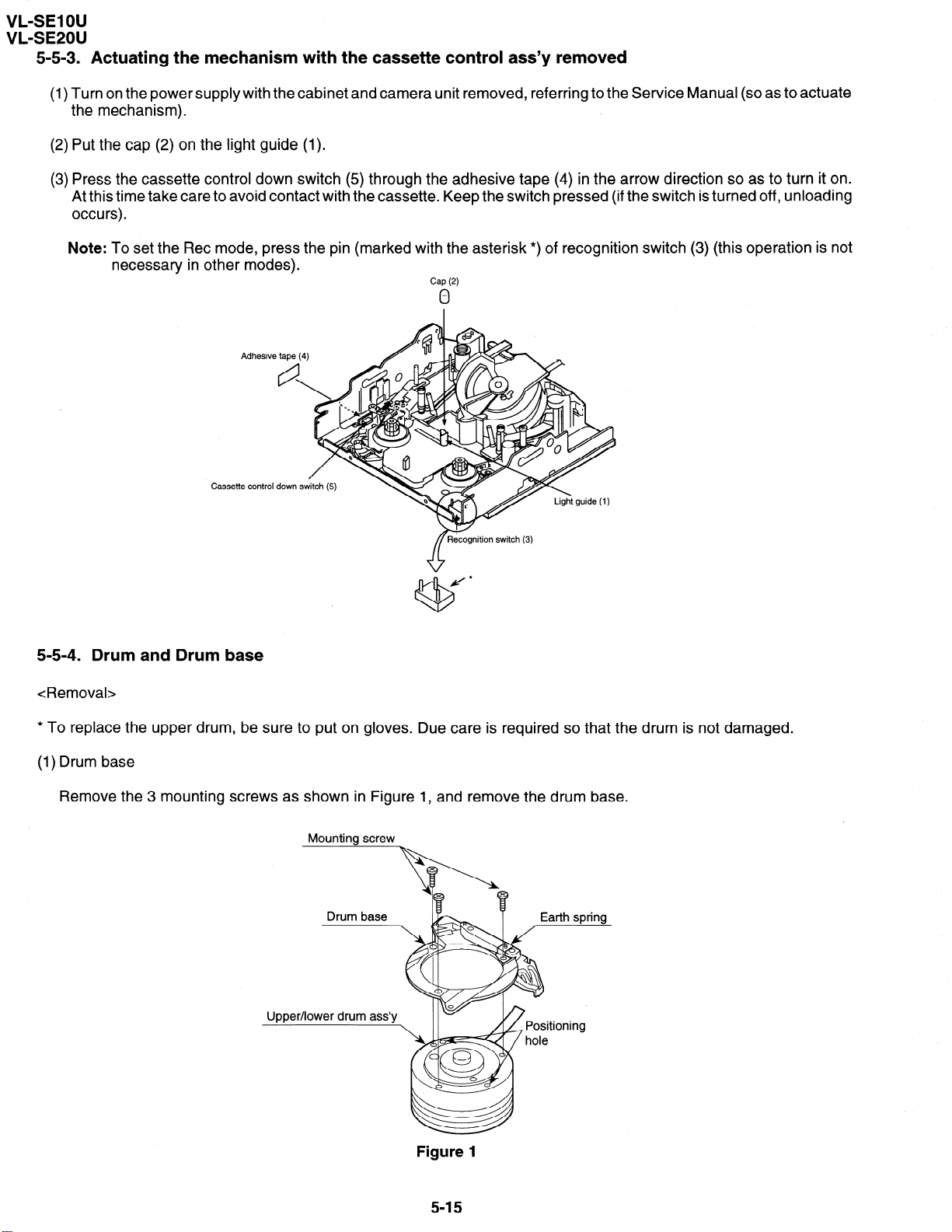
5-5-3. Actuating the mechanism with the cassette control as&y removed
(1) Turn on the power supply with the cabinet and camera unit removed, referring to the Service Manual (so as to actuate
the mechanism).
(2) Put the cap (2) on the light guide (1).
(3) Press the cassette control down switch (5) through the adhesive tape (4) in the arrow direction so as to turn it on.
At this time take care to avoid contact with the cassette. Keep the switch pressed (if the switch is turned off, unloading
occurs).
Note: To set the Ret mode, press the pin (marked with the asterisk *) of recognition switch (3) (this operation is not
necessary in other modes).
Cap (2)
0
Cassette control down s
5-5-4. Drum and Drum base
<Removal>
* To replace the upper drum, be sure to put on gloves. Due care is required so that the drum is not damaged.
(1) Drum base
Remove the 3 mounting screws as shown in Figure 1, and remove the drum base.
Mounting screw
Upper/lower drum ass’y
Figure 1
5-15
Page 31

(2) Drum motor stator
Remove
the stator mounting
screw with the hexagonal wrench as shown
n Phase matching
Motor stator
Stator
I
in Figure 2,
hole
remove the
motor
VL-SE1 OU
VLLSE2OU
stator.
Upper/lower drum ass’y
\
Figure 2
(3) Upper drum ass’y
\
Remove the upper drum ass’y from the lower drum ass’y as shown in Figure 3.
At this time take care so as not to lose the gap shim.
Upper drum ass’y
Gap shim
,
Motor rotor ass’y and rotary
(4
transformer rotor ass’y
Remove the 2 rotor mounting screws as shown in Figure 4, and remove the motor rotor and the rotary transformer ass’y.
Rotor mounting screw
=TTJ
drum ass’y
Figure 4
5-16
Page 32

VL-SE1 OU
VL-SE20U
(5) Balancer
Remove the balancer mounting screw as shown in Figure 5, and remove the balancer.
(6) Lower drum ass’y
Remove the FPC mounting screw from the lower drum ass’y as shown in Figure 6.
Balancer mounting screw
Balancer
v
Upper drum ass’y
Figure 5
F-PC mounting screw
Lower drum ass’y
Figure 6
<Installation>
Install the upper drum in the reverse order of removal.
Balancer
Mount the balancer to the upper drum ass’y with the balancer mounting screw. The screw tightening torque must be
0.1 Nom (tighting torque 1 kgcm). (Figure 5)
Motor rotor, rotary transformer rotor ass’y
Clean the contact surfaces of rotor ass’y holder and upper drum ass’y, and ascertain that there are no contamination
and flaws.
Next, adjust the phase so that the positioning pin of rotor ass’y is inserted into the positioning hole of upper drum, and
tight fit the rotor ass’y to the lower surface of upper drum ass’y (Figure 7).
Mounting screw hole
h
1
Rotary transformer
Rotor ass’y
area)
Rotary transformer
rotor
pin.
Figure 7
5-17
Page 33

VL-SE1 OU
VL-SE2OU
In this state put the motor rotor on the upper surface of upper drum ass’y, and tighten the mounting screw. At this time
make sure that the head screw in the three places isvisible through the motor rotor hole (Figure 8). The screw tightening
torque must be 0.1 N-m (1 kgcm).
Rotor mounting screw
yEK
L ch
Head mounting
Rotary transformer
Alignment position (3 pcs.)v -
G
Figure 8
(3) Lower drum ass’y
Tighten the FPC mounting screw to the lower drum ass’y. The screw tightening torque must be 0.08 N-m (tighting torque
0.8 kgcm). (Figure 6)
(4) Upper drum ass’y
After fitting the gap shim which was removed when the upper drum ass’y was dismantled to the shaft of lower drum
ass’y, fit the upper drum ass’y. (Figure 3)
At this time slightly turn the upper drum ass’y by hand to ascertain that RTr does not scrape. If scrape is found, replace
the gap shim with the gap shim packaged together with the replacement upper drum ass’y.
(5) Drum motor stator
Fit the motor stator to the shaft. Then, apply the preliminary pressure 0.07 N*m (0.7 kg) to the motor stator, tighten the
stator mounting screw. The tightening torque must be 0.15 N-m (1.5 kgcm).
Install the stator so that the chassis line is nearly parallel with the motor stator straight section when it is installed on
the chassis. (Figure 9)
(6) Drum base
Align the positioning pin, and tighten the screws
Stator
screw
Motor stator
(3 PCS.).
Figure 9
5-18
Arrange parallel.
Chassis line
FPC
/ I
stator
board
Page 34

VL-SE1 OU
VL-SE20U
(7) Drum ass’y
Install the drum ass’y on the main chassis, and tighten the screws (3 PCS.).
(8) Tape guide
Align the positioning pin, and tighten the screw (one PC.).
5-5-5. Phase matching
The phase of the following parts must be matched as shown in the figure below.
(Ascertain that the A marks and round holes align.)
(1) Lo relay gear (2) Main cam (3) Sub-cam
Lo relay gear
(4) Mode switch
Phase alignment mark Phase alignment mark
(AMaW
(Round hole)
- Mode switch
5-6. MECHANISM ASSEMBLING METHOD
(l)Adjust the phase of each part.
(2) Install screws and washers.
(3) Install the segment gear, T arm guide and the M-function lever. Install the eject lever.
a
B
Move claw to
Item
a S Tight Ml .4 x 3 70 mN*m (0.7 kgfcm)
B ar0.8-03.0-to.2
Tiqhtening torque
Quantity
1
1
5-19
Page 35

VL-SE1 OU
(4) Install the loading block assembly and the capstan motor.
(5) Install the drive gear. At this time, pay attention to the direction of gear. (The small gear must be located in the chassis
side.)
Item Tightening torque Quantity
A S Tight Ml .4 x 2.5
a S Tight Ml .4 x 3
, Install the
motor under
this plate.
I
70 mN*m 1
70 mN*m
VL-SE20U
4
_
Position the small gear of the drive towards
the chassis.
(6) Install the guide rail assembly.
insert the
and slide it down.
.
0
hb
Make sure not to
deform the arm.
Insert the part in the rail
and slide it down.
Page 36

VL-SE1 OU
VL-SE20U
(7) Install the guide rail assembly taking care to position it correctly.
Item
A S Tiaht Ml .4 x 2.5
1 B 1 S Tiaht Ml .4 x 4
1 C 100.8~03.0-to.2
D 02.1~05.0-to.25
a S Tight Ml .4 x 3 70 mN.m
deform the arm. lot
Align the marks on the parts.
Tightening torque Quantity
70 mN.m 2
40 mN*m
1
l
I
I
1 I
1 I
1
1
Square Hollow Mark
\
/
Segment gear
Su
arm Ass’y
Triangle Mark
/
T Lo arm Ass’y
5-21
Page 37

(8) Install the drum assembly in the chassis.
(9) Install the tape guide in the drum assembly.
(10) Install the Si roller.
VL-SE1 OU
VL-SE20U
Item
A S tight Ml .7 x L5.3
B S tiaht Ml .7 x L2.5
Tightening torque
100 mN*m
60 mN-m
Si roller
a
&
4 Roller spring
@
Quantity
3
1
A
Tape guide
Drum assembly
/
Chassis drawing
0
5-22
Page 38

VL-SE1 OU
VL-SE20U
(11) Install the slide chassis.
T arm guide
\/
/
\
Item
A Ml .4 x 1.5 04.0
B
Ml .4 x 1.5 03.5 40
Tightening torque
40 mN*m
mN-m 3
Quantity
1
Main cam pin
I
I
\
\
\
\
N
_I)
3
Slide this part towards the T arm.
Place the slide chassis
li
nl
on the guide rail.
\
Insert the main cam pin into the hole of
cam of slide chassis.
0
+ Sup reel base
I
I
/
0
0
5-23
Page 39

(12) Install in the following order: T guide lever spring, T guide lever, pinch lever.
(13) Install the swing arm.
(14) Install the right guide holder.
A S tight Ml .4 x 2.5 70 mN*m
Item Tightening torque
B CW lzrO.8-lzr3.0-to.2 70 mN*m
VL-SE1 OU
VL-SE2OU
Quantity
1
1
Pinch lever
Attach to hook
Tu guide lever SPR
Attach to hook
care of position.
Pinch lever
The pinch lever
is positioned on
Stopper
the stopper.
aB
Secure on back side
Take care not to bend the tension band
5-24
Page 40

VL-SE1 OU
VL-SE20U
6. ADJUSTMENT CM= VCR
6-I. ADJUSTMENT OF VCR SECTION 6-l-l m Before starting the electric circuit adjustment
0 Electric circuit adjustment becomes necessary, in most cases, when any of the wear mechanical parts or the video head
has been replaced. Before starting the electric circuit adjustment, be sure to check that the mechanical parts work well
(i.e., the mechanical parts have all been perfectly adjusted). In case a trouble or troubles are found in the electric
circuitry, be sure to pinpoint the cause(s) by using the measuring instruments described below. After locating the trouble
spot(s), then proceed to repair, replacement or adjustment. Do not change the positions of the controls when adequate
measuring instruments are not available.
0 In order to implement a higher-density, smaller machine, most of the electric circuit parts used on the Circuit Boards
are of small-sized, surface-mounted type. For replacing part(s) as after-sales service, work with a soldering iron as
speedily as possible. The heat resistance of the surface-mounted components is poor, when compared with the larger-
sized discrete parts used for television sets and stationary decks, owning to their small sizes. Therefore, exercise due
care to avoid long-time exposure of the pins of these parts to the heat of the soldering iron which may possibly damage
them. Such care should be exercised especially for chip-layer capacitor replacement. It is advisable to use a
temperature-controlled ceramic soldering iron (temperature at the tip: 250°C, contacting time: less than 5 seconds).
< Adjusting the video/LCD section >
0 Measuring instruments:
*Color monitor TV set
*Oscilloscope
*Vector scope
*Digital voltmeter
*Frequency counter
*DC power supply
*Signal generator (NTSC pattern generator LCG-401/401 YC: Leader-made)
*Audio generator (CR oscillator)
*Video recording tape (For Y/C, audio and servo adjustments)
*Alignment tapes (JiGWR2-1 NP, VR2-ATOC, JiGWR5SNSP)
*AC adapter
*DC cable (AC adapter accessory)
*AV output cable (accessory)
*Video extension cables
6-1
Page 41

6-1-2. Servicing the VCR section Adjustment 6-1-2-l. Typical connections
Extension Cable etc.
I Nom I
1 Extension Cable Inverter-VCR (7pin) QCNW-1265TAZZ AX
4 Extension Cable MECHA-VCR (70pin) QCNW-1534TAZZ BS
NAME PART NO. 1 Code 1 CONFIGURATION I REMARKS
VL-SElOU
VL-SE20U
_i
5 Connector fitting and withdrawing
extractor
Connector fitting and withdrawing
/ ’ 1 tweezers
Service remote control RRMCG0033TASA BT
7
10 Extens IOm cable zoom camera QCNW-I 540TAZZ AZ
SW-VCR (6pin)
II Extens IOm cable LCD-VCR (24pin) QCNW-I 382TAZZ BD
ECHANISM
SC305
\ \
efl insulating sleeve
1
1
QCNW-1540TAZZ
I I
CAMERA
CABINET
r
1
P4702
7 QSW-Z0293TAZZ 1 \b” 1
QSW-Z0289TAZZ
@
I ’
, ’
VCR UNIT
SC902
SC4701 SC4702 SC804 SC901
6-2
n
QCNW-1265TAZZ
QCNW-1382TAZZ
Page 42

VL-SE1 OU
VL-SE20U
l Types of test modes
TEST No. Title
1 Sensors off
All sensors but the cassette controller switch, dew sensor
Contents
and battery sensor stay off.
3
Automatic battery sensor Battery sensor’s input voltage put in memory.
adjustment
4
5
6
7 1 VCR adiustment mode IVCR adjustment mode
I
8
Battery adjustment error Battery sensor’s adjustment errors are displayed at the
display
PASS mode
right of the “past errors” area.
Track shift mode (l/4 shift)
Camera adjustment mode Camera adjustment mode
Automatic switching point Play standard tape and call this mode. Switching point is
adjustment (STOP ADJ) automatically adjusted.
@ When the battery adjustment mode is selected from the camera adjustment mode with a cassette with the erase
protection tab, the VCR is automatically put in the REC mode.
Sensor on/off
All sensors on
All but sensors
on
All sensors on
[VCR
interrupted]
I I
0 Below discussed are these seven test modes.
@ [TEST No. I] Sensors off mode
All the sensors, except for the cassette controller switch, dew sensor and battery sensor, stay off. This
enables to bring the VCR in the loading mode without tape. The VCR/camera performance can now
be checked with no tape inside.
@ [TEST No. 31
Automatic battery alarm adjustment
Used to automatically adjust the voltage level which makes the “battery” appear on the LCD display.
@ [TEST No. 41 Battery alarm check/error display
0 The difference between the preset battery alarm voltage and the current supply voltage is displayed
as follows.
0 A past error is displayed at the right of the current battery alarm error.
@ [TEST No. 51
PASS mode
Used to adjust the tape travelling condition. The tracking is shifted by l/4 from the center to make the
tape running-related RF envelope fluctuations easier to observe.
@ [TEST No. 61
Camera adjustment mode
Used to adjust the camera section. (For details, see Servicing the Camera Section.)
@ [TEST No. 71
VCR adjustment mode
Used to adjust the VCR section. (For details, see Servicing the VCR Section.)
I
0 [TEST No. 83
Automatic switching point adjustment
Used to automatically adjust the playback switching point. (For details, see Automatic Adjustment of
the Playback Switching Point.)
6-l-2-2. Setting up the VCR section adjustment mode (camera section adjustment)
0 Select adjustment items by using addresses. Rewrite the adjustment data to change the settings.
Below shown the adjustment procedures and on-screen display.
____‘________‘__‘__5
Enlarged view
(CAM AD4) camera ..----~~._~~.__......_~
V
00 00
(Address) (Data)
ADJ+VCR,%D
;VADJi
T-07
6-3
Page 43

VL-SEIOU
VL-SE20U
Procedural steps
@ Turn up or down the flashing hexadecimal number with the FF or REW key to select the
address of a desired adjustment item. (Initial address: OOH)
Note: The addresses change as follows. 7E - 7F - 00 - 01 - 02
@ Press the PB key to read the data of the selected address.
@ Turn up or down the data setting with the FF or REW key. The data display starts flashing.
@ Press the PB key again to write the data setting into the selected address.
.
@ Press the STOP key in the above step @ or @, and the screen returns back to the step 0.
When the FF or REW key is held down for 0.3 second or longer, the address selection is repeated in cycles of 100 msec
The data setting changes by + 4 by holding the key down for 2 seconds or longer.
Display
( : flashing)
V ADJ
V ADJ
2C A3
V ADJ
2c
V ADJ
2C 72
V ADJ
6-1-2-3. Battery shut-off voltage adjusting method
Supply power to the main unit, using the variable-voltage DC power supply (range of 2.5V to 5V).
1)
Set the CAM/OFF/VCR SW to CAM to switch to the camera mode.
2)
Load a recordable tape and set the main unit to CAM REC. PAUSE.
3)
Set the main unit to TEST mode No. 3, and start recording.
4)
Measure voltage between TL901(+) and TL903(GND), and adjust the supply voltage to 3.OV.
5)
The adjustment is complete if “BATTERY” is displayed on the monitor screen for a second when the PLAY key of
6)
operation unit is pressed.
The adjustment is regarded as proper if the auto shut-off is actuated after the warning is displayed when the TEST mode
7)
is cancelled.
*
In case of automatic adjustment of shut-off voltage, adjustment is impossible if voltage is above 3.OV + 0.2V.
If the adjustment is made at 2.9V or below, the low-voltage operation may become unstable.
l Types of test modes
Any of the eight test modes can be set up by changing the input voltage at pin (54) of IC703. During any test mode, the
REC Start/Stop commands are not accepted.
5v
Adjustment tool
1.2k 1.5k 2.2k 3.3k 5.6k 10k 33k
Use the SW2 thru SW9 switches on the adjustment tool to select the following test modes.
SW No.
2
3
4
Title
Sensors off
Mechanism adjustment mode @ Automatic SP/LP detection prohibited
Automatic battery sensor
adiustment
Error display
Ba%rcdFstmenterror%$iy aEGe=oz
PASS mode
Camera adjustment mode
VCR adiustment mode
Automatic switching point 1 Play standard tape and call this mode. Switching point is automatically
adjustment (STOP ADJ)
All sensors but the cassette controller switch, dew sensor and battery
sensor stav off.
@ Different-mode detection prohibited
@ ATF sampling limited to center
Battery sensor’s input voltage put in memory.
Past errors appear on the counter display of the viewfinder.
adjuxrnGtFr= are dispEyedanh=ight rthe -
“past errors” area.
Track shift mode (l/4 shift)
Camera adjustment mode
VCR adjustment mode
adjusted.
Contents
Sensor on/off
All sensors on
All sensors on
All but sensors
on
All sensors on
[VCR
interrupted]
(
@ When the battery adjustment mode is selected from the camera adjustment mode with a cassette with the erase
protection tab, the VCR is automatically put in the REC mode.
6-4
Page 44

VL-SE1 OU
VL-SE2OU
6-1-3. Adjusting the VCR circuit
l Test Points on the Video Circuit Board
owTL60
o+TL714
TL8803-0
u
0 w 0
0 N w
w w w
w
E- &J
I R
0 O
ohTL709
u-l
TL8810-=
TL8819-60
owTL8827
O+==TL 607
TL609--
TL
Tf:
o--_TL713
owTL716
o+-TL701
-TL706
oe===TL9705 8z
O-TL9704
TL4709.-+
TL4710-m0000
18
sTL940
#TL946
TL947-0
tTL905
TL913-O0
TL925-0
TL
TL
TL
TL
u-l
*
cn
2
I
O-TL9 32
mm
-0
COW
TLI
TL
TL
TL
T
T
L9715_ f z
TL931 ",
91o-=+og3;~;;;6
903-++OOe-TL904
912-o~+=TL926
909-o
0
lI w
TL927y
oo-TL91
TL803-0
Oe-TL801
T
90;
3
1
6-1-3-1. Adjusting the power circuit
POWER CIRCUIT ADJUSTMENT PROCEDURE
1. Adjust to LCD-l 5.OV.
2. Check P-CON 4.9V.
3. Check CAM 4.9V.
I--
4. Check CAM 2.9V.
I
5. Check LCD 13.W. Turn on power (camera).
6. Check LCD 7.OV.
I---
I
I
7. Check CAM 15.OV.
8. Check LCD -7.OV.
I
0 Turn off power.
Page 45

POWER CIRCUIT ADJUSTMENT METHOD
0 Input 6V from the battery terminal, and set the power switch to the camera side.
1. Adjustment to LCD-15.0V
1) Make an adjustment so that the digital voltmeter indicates -15OV + 0.05V.
2. Checking of P-CON 4.9V
1) Check that the digital voltmeter indicates 4.9V + O.lV.
3. Checking of CAM 4.9V
1) Ascertain that the digital voltmeter indicates 4.9V + O.lV.
4. Checking of CAM 2.9V
1) Ascertain that the digital voltmeter indicates 2.9V& O.lV.
5. Checking of LCD 13.5V
1) Ascertain that the digital voltmeter indicates 13.5V + 0.3V.
Measuring instrument
Measuring terminal
Adjustment address
Standard
Measuring instrument
Measuring terminal
Adjustment address
Standard
Measuring instrument
Measuring terminal
Adjustment address
Standard
Measuring instrument
Measuring terminal
Adjustment address
Standard
Measuring instrument
Measuring terminal
Adjustment address
Standard
VL-SE1 OU
VL-SE20U
Digital voltmeter
TL909
20H
-15ov + 0.05v
Digital voltmeter
TL905
4.9v + O.lV
Digital voltmeter
TL906
4.9v +, O.lV
Digital voltmeter
TL931
2.9v I!I O.lV
Digital voltmeter
TL913
13.5v + 0.3v
6. Checkina of LCD 7.OV
Ascertai;that the digital voltmeter indicates 7.OV + 0.25V.
Checking of CAM 15.OV
1) Ascertain that the digital voltmeter indicates 15.OV - 0.2V /
+ 0.25V.
8. Checking of LCD -7.OV
1) Ascertain that the digital voltmeter indicates -7.OV + 0.5V.
(b Turn off power supply.
Measuring instrument
Measuring terminal
Adjustment address
Standard
Measuring instrument
Measuring terminal
Adjustment address
Standard
Measuring instrument
Measuring terminal
Adjustment address
Standard
Digital voltmeter
TL914
7.OV * 0.25V
Digital voltmeter
TL910
15.OV - 0.2V / + 0.25V
Digital voltmeter
TL911
-7.ov + 0.5v
6-I-4. Adjustment of system controller and servo circuit 6-1-4-l. Adjustment of playback switching point
1) Play back the alignment tape (JiGWR5-SNSP)
2)Press the “CONTINUOUS PUSH” and “TEST MODE
SELECTION” of adjustment remote controller to set the
test mode.
At this time the numeral of “TESTOI” blinks.)
3) Using the “FF” and “REW” keys, select “TEST08”, and press the playback key to set the SW-P adjustment mode.
4)After a while the adjustment is completed, and operation stops automatically.
In case of adjustment failure the tape is ejected automatically.
1 Measurina instrument 1 Oscilloscope
1 Playback
1 Adjustment address 1 30h
I Tape
1 Alignment tape (JiGWR5-5NSP)
1
6-6
Page 46

VL-SE1 OU
VL-SE20U
Only in the case when the satisfactory result was not obtained by the adjusting method described above, perform the
following adjustment.
1)Connect each signal to the oscilloscope.
lch: Video output . . . TL801
2ch: H-SW-P . . . . . . . . . . TL405
GND: GND . . . . . . . . . . . . . . . TL802
2) Play back the alignment tape (JiGWR55NSP)
3) Press the “CONTINUOUS PUSH”and “VCR ADJUSTMENT" of adjustment remote controller to set the VCR adjustment
mode.
Select the address 30h, set the sync slope of oscilloscope to (-), adjust the data with “REW” and “FF’: so that
the interval between the trigger point and the V sync
signal is set to 6H, and fix the data with the “PLAY” button.
(See Figure 6.1.1.)
+6~-
------A
3H-4
I
I
I
I
I
i V sync signal
*6~‘k-3H---++-
+
3H-4
i V sync signal
Then, set the sync slope to (+), and ascertain that the
interval between the trigger point and the V sync signal
has been set to 6H. (See Figure 6.2.2.)
6)Keep the STOP key pressed for about 3 seconds to exit
UlnJL
Figure 6.1 .I Figure 6.2.2
from the adjustment mode.
6-l-5. Y/C circuit adjustment method
Input signal conditions
Video signals generated by a pattern generator are used to make electric adjustments in a Y/C circuit. Thus this signal
must conform to the standards prescribed for adjustment signals.
Use an oscilloscope to check that the video signal is terminated with a 75 Cl resistor, the amplitude of the sync signal
component, video component and burst signal are approx. 0.3 Vp-p, 0.7 Vp-p and 0.3 Vp-p, respectively and that they
are flat. The relative level of the burst signal and the red signal shall be 0.30:0.66.
The color bar used in an electrical adjustment is shown in Figure A.
-White (approx. 100%)
I ’
Red (approx. 0.6 VP-P)
L---- Horizontal sync signal
Figure A Color bar signal produced by a pattern generator
* When a pattern generator is not used
Shoot a color bar chart (JiGCHART-4) using a perfectly adjusted video camera.
A signal from a perfectly adjusted video camera shooting a color bar chart (JiGCHART-4) can be used as an adjusting
signal if the lighting can be set to meet the following conditions: output (75 Q terminated), the amplitude of the sync signal
component, video component and burst signal are approx. 0.3 Vp-p, 0.7 Vp-p and 0.3 Vp-p, respectively. The relative
level of the burst signal and the red signal shall be 0.30:0.66. This is shown in Figure B.
White (approx. 100%)
Approx. 0.7 VP-P
L_----- Red (approx. 0.6 V p-p)
- Horizontal sync signal
Figure B Color bar signal produced by a video camera
6-7
Page 47

1. Adjustment of fixed data writing
ADD DATA
23
25 00
26
00
DO
VL-SE1 OU
VL-SE20U
(l)Before starting Y/C adjustment, be sure to write the
specific data in the addresses listed left.
If the data listed left is written after Y/C adjustment,
adjusting values may deviate.
*
Before starting Y/C adjustment, write 00 to the address
31.
*
At the end of Y/C and LCD adjustment, write FF to the
address 31.
2. Adjustment of input Y level
Measuring instrument Oscilloscope
Mode
I Input sianal
Measuring point
, Adjustment address 32
Adiustment level
(1)lnput the color bar signal into the video input/output terminal in the VCR STOP mode..
(2)Enter the VCR adjustment mode with an adjustment remote control, and select the address
Select the address, using the FF or REW key, and fix it with the PB key.
(3)Make an adjustment so as to get 500 mVp-p between SYNC TIP and WHITE PEAK on TL801 or TL8826.
Select the data, using the FF or REW key, and fix it with the PB key.
After the adjustment, press the STOP key, and exit from the adjustment address 32.
3. Adjustment of playback Y level
1 Measuring instrument 1 Oscilloscope
Mode PB
Playback signal
Measurinq point TL801 or TL8826
Adjustment address 27
Adjustment level 500 mVp-p + 20 mVp-p
(l)Set the color bar tape for adjustment (JiGWRS-SNSP).
(2)Enter the VCR adjustment mode with an adjustment remote control, and select the address 27.
Select the address, using the FF or REW key, and fix it with the PB key. (It will automatically set the playback mode.)
(3)Make an adjustment so as to get 500 mVp-p between SYNC TIP and WHITE PEAK on TL801 or TL8826.
Select the data, using the FF or REW key, and fix it with the PB key.
After the adjustment, press the STOP key, and exit from the adjustment address 27.
VCR STOP
1 Color bar l
TL80l or TL8826
500 mVD-D +I 20 f’d/D-D
Color bar (JiGWR5-5NSP)
LCD OPEN +TL801
I
32 .
LCD OPEN +TL801
4. Adjustment of Y-FM carrier f0
Measuring instrument Frequency counter
Mode VCR STOP
Input signal 1 No input
Measurina point
Adjustment address 33
Adjustment level
(1)lnput the no-signal into the video input/output terminal in the VCR STOP mode.
At this time, do not pull out the jack on the Viewcam side.
(2)Enter the VCR adjustment mode with an adjustment remote control, and select the address 33.
Select the address, using the FF or REW key, and fix it with the PB key.
(3)Make an adjustment so that the frequency counter indicates 4.2 MHz on TL7401.
Select the data, using the FF or REW key, and fix it with the PB key.
After the adjustment, press the STOP key, and exit from the adjustment address 33.
I TL7401
4.20 It 0.02 MHz
6-8
Page 48

VL-SE1 OU
VL-SE20U
5. Adjustment of Y-FM deviation
Measuring instrument Oscilloscope
Mode
Input signal
Measurina point
Adjustment address 34
Adiustment level
REC/PB (self-playback/recording)
Color bar
TL801 or TL8826
500 mVp-p & 20 mVp-p
500 mVp-p
7
LCD OPEN +TL801
LCD CLOSE+TL8826
(l)Set the recordable tape.
Before entering the adjustment mode, make self-playback/recording of color bar with an e
(2
Measure whether the playback output at this time is 500 mVp-p on TL801 or TL8826.
Enter the VCR adjustment mode with an adjustment remote control, and select the address 34.
(3
Select the address, using the FF or REW key, and fix it with the PB key.
When decreasing by 10 mVp-p as compared to the measurement value of (2), increase the data of address 34 by about
(4
5 (digit). (Reference)
When increasing by 10 mVp-p as compared to the measurement value of (2), decrease the data of address 34 by about
5 (digit). (Reference)
Select the address, using the FF or REW key, and fix it with the PB key.
(5)Release the adjustment mode, and make self-playback/recording again. When the measuring value at this time is in
the standard value, the adjustment is completed. If it is not in the standard value, repeat the steps (2) - (4).
(6)After completing the adjustment of (5), check the adjusting value of Y-FM carrier f0 (4.2 MHz in no input).
When the measuring value exceeds the standard value of carrier f0,
make an adjustment of Y-FM carrier f0 again.
ternal output.
l-l
6. Adjustment of Y recording current
Measuring instrument Oscilloscope
Mode
Input signal
Measurina point
Adjustment address 35
Adiustment level
(1)lnput the color bar signal into the video input/output terminal in the VCR STOP mode.
(2)Enter the VCR adjustment mode with an adjustment remote control, and select the address 35.
Select the address, using the FF or REW key, and fix it with the PB key.
(3)Make an adjustment so that the SYNC TIP portion gets 200 mVp-p on TL7401.
Select the data, using the FF or REW key, and fix it with the PB key.
After the adjustment, press the STOP key, and exit from the adjustment address 35.
VCR STOP
Color bar
TL7401
200 -O- 10 mVp-p
. C-SYNC
m-451) 1 1
200mVp-p
I I
I
7. Adjustment of comb filter
Measuring instrument Oscilloscope
Mode
Input signal
Measuring point
Adjustment address
Adiustment level
(1)lnput the color bar signal into the video input/output terminal in the VCR STOP mode.
(2)Enter the VCR adjustment mode with an adjustment remote control, and select the address 36.
Select the address, using the FF or REW key, and fix it with the PB key.
(3)Make an adjustment so as to minimize the chroma component on TL404.
Select the data, using the FF or REW key, and fix it with the PB key.
After the adjustment, press the STOP key, and exit from the adjustment address 36.
(4)Enter the VCR adjustment mode with an adjustment remote control, and select the address 37.
Select the address, using the FF or REW key, and fix it with the PB key.
(5)Make an adjustment so as to minimize the chroma component on TL404.
Select the data, using the FF or REW key, and fix it with the PB key.
After the adjustment, press the STOP key, and exit from the adjustment address 37.
(6)Repeat the steps (2) - (3).
VCR STOP
Color bar
TL404
Phase: 36, Gain: 37
Minimum chroma component
Minimum chroma component
6-9
Page 49

8. Adjustment of chroma emphasis f0
VL-SE1 OU
VL-SE20U
Measuring instrument Oscilloscope
Mode VCR STOP
Input signal
Measuring point
Adjustment address 38
Adjustment level Minimum chroma component
(1)lnput the color bar signal into the video input/output terminal in the VCR STOP mode.
(2)Enter the VCR adjustment mode with an adjustment remote control, and select the address 38.
Select the address, using the FF or REW key, and fix it with the PB key.
(3)Make an adjustment so as to get minimum chroma component on TL7402.
Select the data, using the FF or REW key, and fix it with the PB key.
After the adjustment, press the STOP key, and exit from the adjustment address 38.
9. Adjustment of C recording current
Measuring instrument Oscilloscope
Mode VCR STOP
Input signal Color bar
Measuring point TL7402
Adjustment address 39
Adjustment level 175 + 10 mVp-p
(1)lnput the color bar signal into the video input/output terminal in the VCR STOP mode.
(2)Enter the VCR adjustment mode with an adjustment remote control, and select the address 39.
Select the address, using the FF or REW key, and fix it with the PB key.
(3)Make an adjustment so that the amplitude of red portion gets 175 mVp-p on TL7402.
Select the data, using the FF or REW key, and fix it with the PB key.
After the adjustment, press the STOP key, and exit from the adjustment address 39.
Color bar
TL7402
Minimum chroma component
t
Red part
6-l-6. Adjustment of audio circuit
1. Adjustment of filter f0
1 Measuring instrument 1 Oscilloscope
1 Mode
Input signal (tape) JiGWR2-1 NP or
1 Measuring terminal 1 TL605/AUDIO.OUT
I Adjustment address l 21
I Adjustment value I Clear the waveform
Audio Check
Checking of self-recording/playback
I Measuring instrument I Valve voltmeter (oscilloscope)
1 Mode
Input signal (tape) 400 Hz, -8 dBs (872 mVp-p)
Measuring terminal Audio IN/OUT
I Adjustment address l -
I Adjustment value
I PB I
JiGWR55NSP (Color bar)
1 REC + PB
I -8 dBs * 4 dBs (580 to 1370 mVp-p) I
Set the alignment tape (JiGWR2-INP or VR2-ATOC or
JiGWR5-SNSP (Color bar))
Using the adjustment remote controller (RRMCGOO33TASA),
set the VCR adjustment mode, and set the address “21”
with the operation switch (FF/REWIND key).
Play back the standard tape.
Using the operation switch (FF/REWIND key), make an
I
adjustment so that the most clear playback waveform is
obtained on TL605.
Press the operation switch (PLAYBACK key) to write the
data.
Press the operation switch (STOP key) to exit from the
address “21”.
(The address “21” blinks.)
Input the audio signal (40OHz, -8dBs) into the Audio line
IN/OUT terminal, and record.
Connect the valve voltmeter (oscilloscope) to the Audio
line IN/OUT terminal.
Play back the record, and ascertain that the output
waveform level is -8 dBs + 4 dBs (580 to 1370 mVp-p on
the oscilloscope).
If there is any deviation from the specified value, perform
adjustment again as stated in items 1) above, and check
again the self-recording/playback level.
6-l 0
Page 50

VL-SE1 OU
VL-SE20U
6-l-7. Adjustment of LCD display circuit
OWTL
605 Q Q
T t
mm
TL8803-0
P
o+=TL709
owTL8825
Q+==-TL8827
TL8810.P
TL8819-00
CM==TL 607
TL601==+0
TL602+@0
TL604-
o%TL9706
o-TL3723
qy=w~;;~
ILlJILL
O0
J
TL9703
‘II
a-+
r-0
mp_
acr)
TL47
TL47
owTL713
ovTL716
o+-TL701
owTL706
o~TL9705Oe-TL946
oe-TL9704
0
0
t
o+=TL940
TL941
cv
2 0
F3
1
I 0
Q s
E-
TL947-0
O+-==TL905
TL913-0'
TL925-0 5 2
O+==TL937
OwTL932 E-
rnco
-0
WW
“4
7lT
TL1925-60 00
TL8807-0 TLy926
9-00 6Qi
TL880
5~fcv
TL971
‘““lo-o$c+;b;;;” +
TL903-OO+TL904
TLg12-oC+TL926
TL909-0
u-l
-+
a, c ;~N~~==+oy=-T"""'
I
TL931 ",
o++=TL943
ojjwTL911
0
1 %
-a
i?
TL803-=+0
O+===-TL801
T
TL9272
TL80i
Adjustment procedures and connections are the same as with the VCR section.
1. Contrast adjustment
Measuring point TL817 (G-OUT)
Address 40
Mode
1 VCR AV input
Adjusting method l)Set the data of address 47 at the address 80.
2) Input white 100% as an AV input.
3)Connect TL805 to GND. (The 1 H inversion stops.)
4)Connect 220 KQ between TL803 and GND.
5)Seeing the waveform of TL817 (G-OUT), make an adjustment between
the white peak and the svnc tip.
Adiustment standard 13” : 3.3V & 0.1 V
Remarks
2. R-W/B adjustment
Measuring point
TL817 (G-OUT) TL816 (R-OUT)
1 Address 141
I Mode
Adjusting method
I VCR AV input
1) AV input: Nonsignal.
2)TL817 (G-OUT): Oscilloscope CHI
TL816 (R-OUT): Oscilloscope CH2
3)Adiust P-P of TL816 becomes
bioaer 0.15V than TL817.
I Adiustment standard I + 0.1 Vp-R
I Remarks
I
I 4” : 3.35v * O.lV
6-l 1
Page 51

3. B-W/B adjustment
Measuring point TL817 (G-OUT) TL818 (B-OUT)
Address 42
Mode VCR AV input
Adjusting method 1) AV input: Nonsignal.
2) TL817 (G-OUT): Oscilloscope CHI
3) TL818 (B-OUT): Oscilloscope CH2
4)Adjust P-P of TL818 become bigger 0.1 V than TL817.
Adjustment standard + 0.1 Vp-p
Remarks
4. VCO adjustment
Measuring point TL808
Address 43
Mode VCR AV input
Adjusting method 1)AV input : NON Signal
2)Connect the frequency counter to TL808, and adjust the frequency.
Adjustment standard 15734kHz * 1 OOHz
Remarks
5. H-position adjustment
VL-SE1 OU
VL-SE20U
Measuring point TL808
Address
Mode
Adjusting method 1) Input the white 100% signal as an AV input.
Adjustment standard 3” : 3.9pec + 0.1 !$sec 4” : 3.4pec + 0.1 Spec
Remarks
6. COMMON PULSE adjustment
Measuring point
Address
Mode
Adjusting method 1)Set the data of address 47 at the address 80.
Adjustment standard
Remarks
7. COM-BIAS adjustment
Measuring point
Address
Mode
Adjusting method
Adjustment standard
Remarks
44
VCR AV input
2)Connect the oscilloscope to TL808, and adjust the pulse width.
--LIFE-
I
TL821
22
VCR AV input
2) Input the white 100% signal as an AV input.
3)Connect the oscilloscope to TL821, and adjust the pulse width.
3” : 6.8Vp-p + 0.1 Vp-p 4” : 6.6 vp-p
LCD panel display surface
45
VCR AV input
1) Input the white 40% signal as an AV input, and set data of address 47 at the address 80.
2)Set the illuminometer (TOPCON IM-3) on the LCD,panel surface (do not allow entry of external
light).
3) Connect the illuminometer to the oscilloscope.
4)Make an adjustment so as to minimize the ripple of output waveform.
Response time: 0.6 set
5) Adjust again if longitudinal stripe appears evidently.
* Or set to the point where the black is settled deepest with the grey scale signal.
Minimum
Make an adjustment after aging for 5 minutes or more.
6-12
Page 52

VL-SE1 OU
VL-SE20U
8. W/B adjustment
Measuring point
Address
Mode
Adjusting method
Adjustment standard Standard monitor
Remarks
9. lnverter input voltage setting (4”)
Measuring point
Address
j Mode
Adjusting method
Adjustment standard 11 =C2
LCD panel display surface
41,42
VCR AV input
l)White fade signal input.
2)Adjust so as to get the same white screen as that of standard monitor. (Adjust again, visually
checking as stated in item 2.3.)
Make an adjustment after aging for 5 minutes or more.
LCD panel display surface
II,12
1 VCR AV input
Set the data of addresses 11 and 12.
12=9B
IRemarks_ I
I
I
6-l-8. Adjustment of View Far circuit
E-E-
n
nn
0
'L613==-$:
TL606-o
se=-TL ,607
Q-TL
cr)
0
lc
iz
n
0
0
TL8803-0 o '
n 1
owTL709
oe===TL713
oe=-TL716
o+-TL701
-TL706
O*
9706
Q-TL9705 Ob---TL946
%i
3722
0
.9703
w owTL941
0 0
p cv
0, cy-)
o+-TL8825
o-TL9704
oe==TL8827
oe===TL940
0-
'L947-0
,TL 905
TL913-Q"
TL925-0
TL
F::
TL
In
-3
0-l
z
n
Q-TL9 32
TL1925-06 66
TL8807-0 TLy926
TL971
TL880
TL88
TL97
glo-og=;#6
903-OOe-TL904
g12-ooeTL926
909-Q
1. VF DATE SETTING
Address
VCR ADJ 1D
1 VCR ADJ 3B
Examples
DATE
23
Ig!5 I
l During IC702(E2PROM) replacement.
l During IC8800 replacement.
6-13
Page 53

2. VF VCO adjustment
Test point
Address
Mode
Procedure
TL8805 (HSY)
VCR ADJ 08
VCR AV input
1) AV input : No signal
2) Connect to the frequency counter, and adjust to the adjustment standard value at address
Adjustment rating
15.634kHz + 1 OOHz
Remarks
Examples
l During IC702(E*PROM) replacement.
l During IC8800 replacement.
3. VF bright adjustment
Test point
Address
Mode
Procedure
TL8811 (VG)
VCR ADJ OE
VCR AV input
1) The input signal must be 3-step wave.
2) Connect TL8825 (KS800 pin 53)‘to GND.
3) Adjust the pedestal interval of waveform of TL8811 to the specified level.
Adjustment rating
7.5kHz + O.lVp-p
08
VL-SE1 OU
VL-SE20U
I
I
I
.
Remarks
Examples
l During IC702(E*PROM) replacement.
l During iC8800 replacement.
4. VF contrast adjustment
Test point
Address
Mode
Procedure
TL8811 (VG)
VCR ADJ OD
VCR AV input
1) The input signal must be 3-step wave.
2) Connect TL8825 (KS800 pin 53) to GND.
3) Change the address 09/OA to 00.
4) Adjust the pedestal -100% interval of wave form of TL8811 to the specified level.
Adjustment rating
0.85 + 0.1 Vp-p
Remarks
Examples
l During IC702(E*PROM) replacement.
l During IC8800 replacement.
GND
, ä ,I 0.85kO.l Vp-p
GND
6-14
Page 54

i/L-SE1 OU
VL-SE20U
5. VFyl adjustment
Test point
Address
Mode
Procedure
Adjustment rating
Remarks
Examples
6. VF sub bright R/B adjustment
Test point View Far panel area
1 Address 1 VCR ADJ OC (R) VCR ADJ OB (B)
1 Mode
Procedure
1 Adjustment rating 1
Remarks
Examples l During lC702(E2PROM) replacement.
TL8811 (VG)
VCR ADJ 09
VCR AV input
1) The input signal must be 3-step wave.
2) Connect TL8825 (KS800 pin 53) to GND.
3) Adjust the pedestal -50% interval of wave form of TL8811 to the specified level.
1.5 + 0.1 vp-p
& ”
GND
l During IC702(E2PROM) replacement.
l During IC8800 replacement.
1 VCR AV input
1) Feed 40% white signal to the AV input jacks and the standard monitor.
2) Adjust the tone of the colour with the VCR ADJ addresses OC and OB until it becomes the
same as that of the standard monitor.
Make this adjustment after 5-minute or longer aging.
l During IC8800 replacement.
r\ 1.5hO.l vp-p
6-l 5
Page 55

6-2. ADJUSTMENT OF CAMERA SECTION 6-2-l. Servicing of camera section
(1) Object, measuring instrument and jigs necessary for camera section servicing
l Gray scale chart l Color bar chart
l Vectorscope
l Extension cable
l Oscilloscope l Halogen light (2 PCS.)
l Video output cable
NO
.
l Color temperature conversion filter HOYA “LB-165”
l Digital voltmeter l Service Remote Control
l Color video monitor
Item Part Cord Price
1 Gray Scale Chart (390 x 520 mm) JiGCHART- CP
l AC adapter
Code
Configuration
VL-SE1 OU
VL-SE20U
Note
2
Color Bar Chart (240 x 320 mm)
JiGCHART- DA
3 Color Temperature JiGHOYA-LB165
Conversion Filter
4 Service Remote Control RRMCG0033TASA BT
2. N: Indicates the new jigs.
l Connections for Camera
BN
Connect FPC
between the
camera and
the VCR.
LENS
CCD PWB
SC6
20pin
1 Spin
6-16
Page 56

VL-SE1 OU
VL-SE20U
6-2-2. Adjustment procedures
This adjusting procedure covers all the steps for conducting the adjustments all the way. There are some steps that may
be skipped, depending on the specific needs for servicing and
adiustment.
1 1. Checking the power supply voltage
t
2. Adjusting the auto focus.
* Preparation: Set the auto focus adjustment mode.
Preparation: Set the camera signal adjustment mode.
4. Adjusting the iris AE
6-2-2-l. Checking the power supply voltage
l Measuring terminal: CAM 4.9V
CAM 2.9V
CAM 15V
CAM -8V
LENS 5V
l Measuring instrument: Digital voltmeter
5. Adjusting the carrier balance and AF noise level
6. Adjusting the burst gain
7. Adjusting the white balance
8. Adjusting the color gain
1 9. Adjusting the auto white balance
6-2-2-2. Auto focus adjustment
l Basic iris adjustment
1 Measuring instrument 1 None
1 Subject
ae
IT P
I Test point
Adjustment address
Adjustment level 09, OA, OB
1) Set up the auto focus adjustment mode. (Write 01 to the address 1 FE)
2) Write the adjustment data 09, OA and OB one after the other to the address 1 FF, the adjustment are as follows.
Data
09
OA
OB
l- I
I- I
one
IN
IFF
Adjustment
Hall offset
I Iris offset
1 Iris close
6-17
Page 57

VL-SE1 OU
VL-SE20U
l Lens adjustment
Measuring instrument None
Subject More than 50 m away
Tape
Test point None
Adjustment address
IFF
Adjustment level 11, 12, 06, 08
1) Set up the auto focus adjustment mode.
(This is unnecessary after the above basic iris adjustment has been made.)
2) Write the adjustment data 11, 12, 06 and 08 one after the other to the address 1 FF. The adjustments are as follows.
3) Write FF to the address 1 FE to exit the auto focus adjustment mode.
1 Data 1 Adjustment
11
Voltage adjustment
12 Optical wide-end adjustment
06 1 Wide-end focus 00 position adjustment 1
08
1 Tele-end focus 00
position adjustment 1
6-2-2-3.
Before starting these adjustments, set up the auto focus adjust.
l Sync level adjustment
Measuring instrument Oscilloscope
Subject
Anything
Tape
I Test point I VIDEO OUT (Terminated in 75Q) I
I Adjustment address I 1 FE
I Adjustment level
I 286mVp-p
I
1H
1) Set up the camera signal adjustment mode. (Write 00 to the address 1 FE)
2) Connect the oscilloscope to the VIDEO-OUT. Adjust the sync level to 286mVp-p.
Video
6-2-2-4.
l Iris AE adjustment
Measuring instrument Oscilloscope
Subject
Gray scale
Tape
Test point
VIDEO-OUT
Adjustment address I 1 FD
Adjustment level 1 700mVp-p
I
1
1) Shoot the gray scale in the standard way. Observe the VIDEO-OUT signal
data of address 1 FD to get an amplitude of 700mVp-p as shown above.
6-2-2-5.
l Carrier balance , AF noise level adjustment
I Measuring instrument I None
Subject
Tape
I Test point
I Adjustment address I 1 FF
I Adjustment level
1) Preparation : write FF to address 19C, 19D, 19E, 19F, 1 AO, 1 Al.
2) Write the data 01 to the address 1 FF.
The following adjustments are automatically
carried on ;
@ Carrier balance adjustment
@ AF noise level adjustment
at AGC Gain Min , AGC Gain Max and Gain up.
Anything
one
IN
I 01
I
on the oscilloscope screen and rewrite the
6-18
Page 58

VL-SElOU
VL-SE20U
6-2-2-6.
l Burst gain adjustment
1 Measuring instrument ( Oscilloscope
Subject
Tape
1 Test point
I Adjustment address I 1 F9
Adjustment level
1) Measure the burst signal level on the oscilloscope. Using the address 1 F9, adjust the burst amplitude to 286mVp-p.
None
1 VIDEO OUT (Terminated in 75 Q)
1286mVp-p
11
286mVp-p
6-2-2-7.
l White balance adjustment
Measuring instrument Vector scope
Subject
Tape
Test point
Adjustment address R-GAIN 010, B-GAIN 012
Adjustment level R-Gain 0 % + 3 %
1) Adjust the spot to the center of vector scope (R-Y : 0%, B-Y : 0%) using address 010 and 012.
Gray scale
VIDEO OUT (Terminated in 75 Q)
B-Gain 0 % If: 3 %
R-Y
Center point
6-2-2-8.
l Color gain adjustment
Measuring instrument
Subject
Tape
Test point
Adjustment address
Adjustment level
Vector scope
Color bar chart
VIDEO OUT (Terminated in 75 Q)
R-Y GAIN ODD
B-Y GAIN ODB
R-Y MAT 0D7
R-Y
R level
B-Y
B-Y
1) Using the address ODD, adjust the R level to a burst ratio of 1.2. With the address ODB, adjust the B level to a burst ratio
of 1.0.
2) Using the address 0D7, adjust the R phase to 100’. With the address OD9, adjust the B phase to 344’.
3) Repeat the above steps 1) and 2).
* 6-2-2-g.
l Auto white balance adjustment
Measuring instrument
Subject
Tape
Test point
Adjustment address R-OUT DOOR 016
Adjustment level
1) Attach the color temperature conversion filter (JiGHOYA-LB165) to the front of the lens.
2) Using the addresses R-OUT DOOR 016 and B-OUT DOOR 018, adjust the spot to the center.
3) Take off the color temperature conversion filter.
4) Write FF to the address 1 FE to exit camera signal adjustment mode.
Vector scope
Gray scale
VIDEO OUT (Terminated in 75 Q)
B-OUT DOOR 018
R-OUT DOOR; 0 I!I 3 %
B-OUT DOOR; 0 + 3 %
6-19
R-Y
B-Y
Center point
Page 59

6-3. TROUBLE SHOOTING
6-3-l. Classification of troubles
VL-SE1 OU
VL-SE20U
No function at all
No tape ejection
No LCD light-up
No picture in EE mode
+
No picture playback
f
No video recording
Streaking at self-recording/playback
w
Noises at regular intervals in playback
-t--)YES
--t)YES
Black streaking
t+
YES
YES
YES
YES
Check the Power circuit and system control circuit.
Check the system control and loading motor
circuit.
Check the invertertransformer and power circuit.
* Check the camera section and Y/C circuit and
LCD circuit.
Check the Y/C circuit and head amplifier circuit.
Check the Y/C circuit and head amplifier circuit.
Check the Y/C circuit and head amplifier circuit.
Check the ATF circuit.
No recorded characters on screen
f
No color in EE mode
No color in playback
No color in recording
No sound
Error message (e.g. E007)
Normal
6-3-2. Troubleshooting for the camera section
No picture
*
L
t-,
t)
t,
t+
)YES
YES
YES
YES
bYES
YES
*YES
YES
Check the LCD circuit and character generator
(IC705).
* Check the camera section and Y/C circuit.
Check the Y/C circuit and head amplifier circuit.
Check the Y/C circuit and head amplifier circuit.
Check the audio circuit.
Check the system controller and CAP MOTOR
DRIVER circuit.
Check the lens drive circuit (IC551) and main
signal line.
Check ICZOI (DSP), and their peripherals. No color
’
No auto white balance function
No auto focus function
No power zoom function
f Normal
)YES
,----+YES
YES
6-20
Check IC501 (camera CPU) and its peripherals.
Check ICXOI, IC551 and their peripherals.
Check IC501, IC551 and their peripherals.
Page 60

VL-SE1 OU
VL-SE20U
7. SYSTEM BLOCK DIAGRAM ~pEgB_“r____,
I
I
POWER (CAMERA)
p”--“-I
I
CAMERA
MICROCOMPUTER
CONVERTOR
I
I
I
I
I ~----“---I
POWER (AT 3.3V)
I
IC2701
POWER (SYS 3.3V)
-111111
I
I
I
I
I
IC703
I
SYSTEMSERVO
CONTROLLER
IC702
Y/C > AUDIO
IC401
*0
In this model, all the circuits of the VCR and camera sections are controlled by IC703 and IC501.
IC601 /
I
I
I
I
I
I
I
I
I
I
I
I
H/A
UNIT
I
j MECHA-
; CHASSIS
I II-II-__-_I-II-II-_I-__-I
7
> MECHA- c
NISM
1
I
I
I
J
1) IC501 and IC401 are controlled with the serial data from IC703.
2) IC702 is a memory that serves to store the adjustment data of the VCR section.
3) IC2 is a memory that serves to store the adjustment data of the camera section.
4) The other circuits and ICs are under the L/H level or the PWM control.
7-1
/ IC800
LCD
CIRCUIT
I
Page 61

Page 62

Page 63

Page 64

Page 65

Page 66

Page 67

Page 68

Page 69

Page 70

Page 71

Page 72

Page 73

Page 74

Page 75

Page 76

Page 77

Page 78

Page 79

Page 80

Page 81

Page 82

Page 83

Page 84

Page 85

Page 86

Page 87

Page 88

Page 89

Page 90

Page 91

Page 92

Page 93

Page 94

Page 95

CCD P.W.B.
VL-SE1 OU
VL-SE20U
Component Side
Wiring Side
SIDE A
J /
SIDE B
P-7 n
0 0 0
Page 96

VL-SE1 OU
VL-SE20U
Page 97

11 n REPLACEMENT PARTS LIST/
EXPLODED VIEWS
ELECTRICAL PARTS LIST
Parts marked with “A II are important for maintaining the safety of the
set. Be sure to replace these parts with specified ones for maintaining
the safety and performance of the set.
Les pieces marquess ‘A ‘sent importantes pour maintenir la securite
de I’appareil. Ne remplacer ces pieces que par des pieces dont le
numero est specific pour maintenir la securite et proteger le bon
fonctinnement de I’appareil.
M HOW TO ORDER REPLACEMENT PARTS”
in USA:
in CANADA:
*MARK : SPARE PARTS-DELIVERY SECTION : ALL JAPAN
To have your order filled promptly and correctly, please furnish
the following informations.
L’ASSEMBLANGE P.C.I. EST UN ARTICLE NON REMPLACABLE
Contact your nearest SHARP Parts Distributor. For
location of SHARP Parts Distributor,
Call Toll-free 1 -IBE800-SHARP
Contact SHARP Electronics of Canada Limited
Phone (416) 890-2100.
1. MODEL NUMBER
3. PART NO.
5. PRICE CODE
A MARK: SAFETY RELATED PARTS
A PIECES: RELATIVES A LA SECURITE
PWB ASSEMBLY IS NOT REPLACEMENT ITEM
2. REF. NO.
4. DESCRIPTION
Ref. No. Part No. *
IC703
IC704
IC705
IC706
IC800
IC801
IC802
IC803
IC901
IC902
IC904
IC905
ICI 701
IC2701
IC3701
lC3702
163703
IC4401
IC8800
IC9800
RH-iX0648TAZZ
or
RH-iX0592TAZZ
or
RH-iX0637TAZZ
VHiNJM2904M-1
RH-iX0598TAZZ
VHiRS5C313/-1
VHiiR3Y29AM-1
VHiNJM2107F-1
VHiNJM4565V-1
VHiLZ95NAl/-1
RH-iX0325TAZZ
VHiTA75SOl F-l
VHiNJM2904M-1
VHiTA75SOl F-l
VHiCXA1814N-1
VHiMB88344F-I
VHiLBl95OV/-1
VHiLB1951V/-1
VHiLB1638M/-1
VHiTL8856FS1
VHiCXA2503A-1
VHiTC7WO8U/-1
Description
I.C.
I.C.
!.C.(VL-SE1 OU)
NJM2904M
I.C.
RS5C313-E2
IR3Y29AM
NJM2107F
NJM4565V
LZ95NAl
MB4484PFVG
TA75SOl F
NJM2904M
TA75SOl F
CXAI 814N/-T4
MB88344PFV
LB1 950V-TRM
LB1 951 V-TRM
LB1 638M-TE-R
TL8856FS(EL)
CXA2503AR-T6
TC7W08FU
VL-SE1 OU
VL-SE2OU
Code
AY
AY
AY
AE
AR
AL
AV
AE
AF
AR
AY
AD
AE
AD
AQ
AV
AQ
AN
AK
AH
AZ
AE
Ref. No. Part No. *
Description Code
PRINTED WIRING BOARD ASSEMBLIES
(NOT REPLACEMENT ITEM)
DUNTK2786QAOO
DUNTK2786QAOl
DUNTK2788QAOO
DUNTK2791 QAOO
DUNTK2800PMOO
RAMP-001 7TAN0
VCR UNIT(VL-SE1 OU)
VCR UNIT(VL-SE20U) -
CAMERA1 UNIT
CAMERA2 UNIT
CCD UNIT
HEAD AMP UNIT
DUNTK2786QAOO VCR UNIT(VL-SE1 OU)
DUNTK2786QAOl VCR UNIT(VL-SE20U)
INTEGRATED CIRCUITS
A CP901 VHiCCP2E63/-1 I.C.
A CP902 VHiCCP2E50/-1
IC401
IC601
IC701
IC702 VHiBR93L56F-1
VHiAN2492F/-1 AN2492FH
VHiLA7458W/-1
VHiRM3329B/-1
I.C.
LA7458W
RS5RM3329B-T2
BR93LC56F-E2
AD
AD
AX
AT
AL
AM
TRANSISTORS
Q401
Q402
Q403
-
-
-
-
Q404
Q405
Q406
Q407
Q409
Q411
Q412
Q413
Q414
Q415
Q601
Q602
Q603
Q701
Q702
Q703
Q704
Q709
Q710
VSRTI N241 U/-l
VSRTI N241 U/-l
VSUMD2/////-1
VSUMD2/////-1
VSRTI P241 U/-l
VS2PA1774R/-1
VS2SC5383F/-I
VSRTI N241 U/-l
VS2SC5384C/-1
VSRTI P241 U/-l
VSRTI N441 U/-l
VSRTI N441 U/-l
VSUPUMTl///-1
VS2SA1298Y/-1
VSDTC144EE/-1
VS2SC4738Yk1
VS2SB12956/-1
VSDTC144EE/-I
VSXP6501///-1
VSUMD2/////-1
VSUMH2/////-1
VSUMH2/////-1
Transistor
Transistor
Transistor
Transistor
Transistor
Transistor
Transistor
Transistor
Transistor
Transistor
Transistor
Transistor
Transistor
Transistor
Transistor
Transistor
Transistor
Transistor
Transistor
Transistor
Transistor
Transistor
AB
AB
AC
AC
AB
AB
AB
AB
AB
AB
AB
AB
AC
AB
AA
AA
AB
AA
AB
AC
AC
AC
11-1
Page 98

VL-SE1 OU
VL-SE20U
Ref. No.
Part No. * Description Code
Ref. No. Part No. *
Description
Q77 7 VSUMH2/////-7
Q772 VSUMH2llW7
Q773 VSUMH2/////-7
Q774 VSUMT2//Wl
Q775
Q776 VSUMT2//W7
Q777 VSUMT2lIW7
Q778
Q77 9 VSUMT2llW7
Q720 VSU MT2/////-7
Q727 VS2SA7774Fb7
Q722 VSUPUMXIWI
Q723
Q803 VSUPUMZIWI
Q804
Q907 VSFP307////-7
Q903 VS2SB72956/-7
Q904
Q905 VSFZT7048Ab7
Q906 VS2SB72956/-7
Q907 VS2SA1973//-7
Q908 VS2SA1973//-7
Q909 VS2SA7973//-7
Q970 VS2SA7973//-7
Q97 7 VSUMA4/////-7
Q972 VSMPLI lllll-7
Q973 VS2SB7723//-7
Q974 VSUMD2/////-1
Q97 5 VSUMD2h’W7
Q976
Q977 VSUMD2/////-7
Q97 8 VSUMD2/////-7
Q97 9 VSUMD2/////-7
Q920 VSUMG2/////-7
Q923 VSUMD2/////-7
Q924
Q925 VS FX803////- 1
Q926
VSUPUMZIWI
VSUMT2/////-7
VSUMH2/////-7
VSUMG2/////-7
VS2SA7 774F/-7
VSUMH2/////-7
VSUMD6/////-7
VSMPLI /////-I
Q927 VSMPLI /l/l/-l
Q928 VSFZTI 048Af-1
Q929 VS2SA7774Fb7
Q933 VSUMD2/////-7
Q934
Q935 VS2SC467 7B/-1
Q936
Q937
Q7402
Q7403 VS2SC5383Fb7
VS2SA7 774F/-7
VSDTA744EEb7
VSDTA744EEb7
VS2SA7989Rbl
Transistor
Transistor
Transistor
Transistor
Transistor
Transistor
Transistor
Transistor
Transistor
Transistor
Transistor
Transistor
Transistor
Transistor
Transistor
Transistor
Transistor
Transistor
Transistor
Transistor
Transistor
Transistor
Transistor
Transistor
Transistor
Transistor
Transistor
Transistor
Transistor
Transistor
Transistor
Transistor
Transistor
Transistor
Transistor
Transistor
Transistor
Transistor
Transistor
Transistor
Transistor
Transistor
Transistor
Transistor
Transistor
Transistor
Transistor
Transistor
AC
AC
AC
AB
AC
AB
AB
AB
AB
AB
AA
AC
AC
AC
AC
AD
AB
AA
AF
AB
AD
AD
AD
AD
AB
AE
AC
AC
AC
AC
AC
AC
AC
AC
AC
AC
AG
AE
AE
AA
AC
AF
AA
AA
AA
AA
AB
AB
Q7404
Q3707
Q3702
Q4407
Q4402
Q4405
Q5407
Q5402
Q5403
Q5404
Q5405
Q7402
Q7403
Q7404
Q7405
Q8402
Q8403
Q8404
Q8405
Q8407
Q8408
Q8409
Q8800
Q8807
Q8802
Q8803
Q9407
D407
D607
D707
D702
D704
D705
D707
D802
D803
D805
D907
D902
D903
D904
D905
D906
D907
D7907
D5407
VSXPI B307//-7
VSUPUMXIWI
VSUMB2/////-7
VS2PA1774Rbl
VS2PA1774Rbl
VS2PA7774Rbl
VS2SC5384W7
VS2SC5384Cb7
VS2PC467 7R/-7
VS2SC5383Fb7
VS2SA1298Y/-7
VS2SA1989Rb7
VS2SC5384C/-7
VS2SA1989Rhl
VSRTI P247 W-7
VSUPUMXIWI
VSRTlN747U/-7
VSUPUMZIWI
VSUPUMXIWI
VS2SC5383Fb7
VS2SC5383Fb7
VSILSAl989Rb7
VSUPUMZIIII-7
VSUMG2/////-7
VSUMG2/////-7
VSDTCI 44EE/-7
VSUPUMXIWI
DIODES AND LED’S
VHDMAI 33///-l
VHDMAI 32K//-7
RH-DXOI 82TAZZ
RH-DXOI 82TAZZ
VHDMAGS727/-7
VHDMAI 32K//-7
RH-DXOI 82TAZZ
VHDMAI 32K//-7
VHDHVC359TR-7
RH-EXOI 89TAZZ
VHDFI J2HWl
RH-EXOI 93TAZZ
VHDI SS355//-7
VHDDA227///-7
VHDFOI J2E//-7
VHDFI J2HWl
VHDFI J2HWl
VHDMA2Sll l/-l
VHDHVU77TRF-7
Transistor
Transistor
Transistor
Transistor
Transistor
Transistor
Transistor
Transistor
Transistor
Transistor
Transistor
Transistor
Transistor
Transistor
Transistor
Transistor
Transistor
Transistor
Transistor
Transistor
Transistor
Transistor
Transistor
Transistor
Transistor
Transistor
Transistor
Diode
Diode
Diode
Diode
Diode
Diode
Diode
Diode
Diode
Zener Diode
Diode
Zener Diode
Diode
Diode
Diode
Diode
Diode
Diode
Diode
AD
AC
AB
AB
AB
AB
AB
AB
AB
AB
AB
AB
AB
AB
AB
AC
AB
AC
AC
AB
AB
AB
AC
AC
AC
AA
AC
AB
AA
AD
AD
AD
AA
AD
AA
AD
AC
AD
AC
AB
AB
AC
AD
AD
AC
AE
11-2
Page 99

Ref. No.
Part No. * Description
VL-SE1 OU
VL-SE20U
Ref. No. Part No. * Description Code
D8800 VHDlT406///-1 Diode
PACKAGEQ CIRCUITS
TH5401 VHHTI 222K41-1
x401 RCRSCOI 13TAZZ
x701 RCRSC0030TAZZ
X702 RCRSC0032TAZZ
X800 RCRSC0087TAZZ
X8800 RCRSC0087TAZZ
Thermistor
Crystal
Crystal
Crystal
Crystal
Crystal
COIL AND TRANSFORMERS
FL701
FL540 1
L401
L402
L403
L404
L601
L602
L603
L701
L702
L703
L800
L802
L803
L804
L805
L805
L806
L901
L902
L903
L904
L905
L906
L907
L908
L909
L910
L911
L912
L913
L914
L915
L916
RCiLB0039TAZZ
RCiLF0367TAZZ
VPAXM220KR88N
VPAWMlOlJ140N
VPAEM151J11ON
VPAEM220J2R9N
VPAXMI 01 K4RON
VPAXMI 01 K4RON
VP-WM220KR71 N
RCiLP0241 TAZZ
VPAXM220KR88N
VPAXM220KR88N
VPAWM47OJGR4N
VPAXM470Kl R7N
VPAXMI OOKR42N
VPAWMI R2JR78N
VPAEM220J2R9N
VPAEM120Jl R9N
VPAWMI OOJ2R6N
RCiLP0226TAZZ
RCiLP0206TAZZ
VPAXMl 01 K4RON
VPAXMI OOKR42N
RCiLPOl GOTAZZ
RCiLP0206TAZZ
VPAXMl OOKR42N
VPAXM2R2MR16N
VPAXMI OOKR42N
VPAXM2R2MR16N
RCiLPO16OTAZZ
RCiLP0206TAZZ
VPAXMI OOKR42N
RCiLP0226TAZZ
VPBAMI OOKR26N
VPBAMI OOKR26N
Oscillation Coil
Coil
Peaking 22pH 10%
Peaking 100pH 5%
Peaking 150pH 5%
Peaking 22pH 5%
Peaking IOOpH 10%
Peaking IOOpH 10%
Peaking 221,~H 10%
Coil
Peaking 22pH 10%
Peaking 22pH 10%
Peaking 47pH 5%
Peaking 47pH 10%
Peaking IOpH 10%
Peaking 1.2pH 5%
Peaking 22pH 5%
(VL-SE1 OU)
Peaking 12pH 5%
(VL-SE20U)
Peaking IOpH 5%
Coil
Coil
Peaking IOOpH 10%
Peaking 10pH 10%
Coil
Coil
Peaking IOpH 10%
Peaking 2.2pH 20%
Peaking IOpH 10%
Peaking 2.2pH 20%
Coil
Coil
Peaking IOpH 10%
Coil
Peaking IOpH 10%
Peaking IOpH 10%
AD
AD
AH
AG
AG
AK *
AK
AE
AH
AC
AC ’
AC
AC
AC
AC
AB
AF
AC ’
AC
AC
AC
AC
AD
AC
AC
AC
AE
AE
AC
AC
AE
AE
AC
AC
AC
AC
AE 8
AE
AC
AE
AC
AC
L917
L918
L919
L920
L921
L922
L923
L924
L925
L926
L927
L928
L929
L930
L931
L932
L1701
L2701
L3701
L4401
L7402
L7403
L7404
L7405
L8401
L8402
L8403
L8404
L8405
L8407
L8408
L8800
L8801
L8802
L8803
L8804
L9800
L9801
A T901
C402
c403
c404
c405
C406
c407
C408
VPBAM2R2M090N
VPBAMI OOKR26N
RCiLPOl GOTAZZ
RCiLP0206TAZZ
VPAXM2R2MRl6N
VPAXMI OOKR42N
RCiLPOl GOTAZZ
RCiLP0205TAZZ
RCiLP0205TAZZ
RCiLP0206TAZZ
RCiLP0223TAZZ
RCiLPOl GOTAZZ
RCiLP0206TAZZ
VPAXM2R2MR16N
VPAXMI 01 K4RON
RCiLP0226TAZZ
VPAXM220KR88N
VPAXM220KR88N
VPAXM2R2MR16N
VPAXM470Kl R7N
VPAEM121 JSRON
VPAEM391 J220N
VPAWMI R8JR98N
VPAEM471 J250N
VPAWM6R8J2Rl N
VPAWMI OOJ2R6N
VPAWM8R2J2R3N
VPAEM121 JSRON
VPAEM471 J250N
VPAEM331 J21 ON
VPAEM471 J250N
VPAWMI OOJ2R6N
VPAWMI OOJ2R6N
VPAWMl OOJ2R6N
VPAWMI OOJ2R6N
VPAWM470J6R4N
VPAWMl OOJ2R6N
VPAWMI OOJ2R6N
RTRNZ0131 TAZZ
Peaking 2.2y,H 20%
Peaking IOpH 10%
Coil
Coil
Peaking 2.2pH 20%
Peaking IOpH 10%
Coil
Coil
Coil
Coil
Coil
Coil
Coil
Peaking 2.2pH 20%
Peaking IOOpH 10%
Coil
Peaking 22pH 10%
Peaking 22pH 10%
Peaking 2.2pH 20%
Peaking 47pH 10%
Peaking 120pH 5%
Peaking 390pH 5%
Peaking 1.8pH 5%
Peaking 470pH 5%
Peaking 6.8pH 5%
Peaking IOpH 5%
Peaking 8.2pH 5%
Peaking 120yH 5%
Peaking 470pH 5%
Peaking 330pH 5%
Peaking 470pH 5%
Peaking IOpH 5%
Peaking IOpH 5%
Peaking 10l_~H 5%
Peaking IOpH 5%
Peaking 47pH 5%
Peaking IOpH 5%
Peaking IOpH 5%
Transformer
CAPACITORS
VCKYCZI CBI 03K 0.01 16V Ceramic
VCKYCZl CB103K
RCKZ0051 TAZZ
VCSATAlAJ106M 10 1 OV Tantalum
VCSATAlAJ335M 3.3 1 OV Tantalum
VCKYCZI HFI 032 0.01
VCSATAlAJ475M 4.7 1 OV Tantalum
0.01 16V Ceramic
Capacitor
50V Ceramic
AC
AC
AE
AE
AC
AC
AE
AE
AE
AE
AE
AE
AE
AC
AC
AE
AC
AC
AC
AC
AC
AC
AC
AC
AC
AC
AD
AC
AC
AC
AC
AC
AC
AC -
AC
AC
AC
AC
AH
AB
AB
AC
AC
AC
AB
AC
11-3
Page 100

VL-SE1 OU
VL-SE20U
Ref. No.
Part No. *
Description Ref. No. Part No.
* Description
Code
c409
c410
c411
C412
c413
c414
c415
C416
c417
C418
c419
C420
C421
C423
C424
C425
C426
C427
C428
c429
c430
c431
C432
c433
c435
C436
c437
C438
c439
c440
c441
C442
c443
c445
C446
c447
C448
c449
c450
c451
c453
c454
c455
c457
C458
c459
C601
C602
VCSATAI AJ475M
RC-KZ0051 TAZZ
RC-KZ0051 TAZZ
RC-KZ0055TAZZ
RC-KZ0055TAZZ
VCKYTVI CB224K
VCSATAlAJ106M
VCSATAI AJ475M
VCSATAI AJI 06M
VCSATAI AJ335M
VCKYCZI CBI 03K
VCCCCYlHH151J
RC-KZ0051 TAZZ
VCKYCYI HB682K
VCCCCYI HH331 J
VCCCCYI HH391 J
VCCCCZI HH270J
VCKYCZI CBI 03K
VCSATAI AJ106M
VCKYCZI HFI 032
VCKYCZI CBI 03K
VCCCCZI HH390J
VCKYCZI CBI 03K
VCKYCZI HFI 032
VCKYCZI CBI 03K
VCKYCZI CBI 03K
VCCCCYI HH471 J
RC-KZ0055TAZZ
VCCCCYI HH391 J
VCKYCZI CBI 03K
VCKYCZI CBI 03K
VCCCCZI HH470J
VCCCCZI HH470J
VCKYCZI CBI 03K
RC-KZ0051 TAZZ
VCSATAlAJ106M
VCKYCZI CBI 03K
VCSATJI AJ476M
VCCCCYI HH820J
VCSAPDI CJI 05M
VCCCCY 1 HH 150J
VCKYCZI CBI 03K
VCKYTVI CB474K
RC-KZ0051 TAZZ
VCKYCYI HBI 03K
VCKYCZI CBI 03K
VCSATAI CJ225M
VCKYTVI CF225Z
4.7
Capacitor
Capacitor
Capacitor
Capacitor
0.22
IO
4.7
IO 1 OV Tantalum
3.3 1 OV
0.01 16V
150p
Capacitor
68OOp 50V Ceramic
330p 50V Ceramic
390p 50V Ceramic
27P
0.01
IO 1 OV Tantalum
0.01 50V Ceramic
0.01 16V Ceramic
39P
0.01 16V Ceramic
0.01 50V Ceramic
0.01
0.01
470p
Capacitor
390p
0.01
0.01
47P
47P
0.01 16V Ceramic
Capacitor
IO
0.01 16V Ceramic
47 1 OV Tantalum
82P
1 .o 16V Tantalum
15P
0.01
0.47 16V Ceramic
Capacitor
0.01 50V Ceramic
0.01
2.2 16V Tantalum
2.2 16V Ceramic
1 OV Tantalum
16V Ceramic
1 OV Tantalum
1 OV Tantalum
Tantalum
Ceramic
50V Ceramic
50V Ceramic
16V Ceramic
50V Ceramic
16V Ceramic
16V Ceramic
50V Ceramic
50V Ceramic
16V Ceramic
16V Ceramic
50V Ceramic
50V Ceramic
I OV Tantalum
50V Ceramic
50V Ceramic
16V Ceramic
16V Ceramic
AC
AC
AC
AD
AD
AB
AC
AC
AC
AC
AB
AA
AC
AA
AA
AA
AB
AB
AC
AB
AB
AB
AB
AB
AB
AB
AA
AD
AA
AB
AB
AB
AB
AB
AC
AC
AB
AE
AA
AC
AA
AB
AC
AC
AA
AB
AC
AC
C603
C604
C605
C606
C607
C608
C609
C610
C611
C612
C613
C614
C615
C616
C617
C618
C619
C620
C621
C622
C623
C624
C625
C626
C627
C628
C629
C630
C631
C632
C633
C634
C635
C636
C637
C638
c701
C702
c703
c704
c705
C706
c707
C708
c709
c710
c711
C712
VCSATJI AJ476M
VCSATJI AJ476M
VCKYCYI HB103K
VCKYCY 1 HBI 03K
VCKYCYI HB103K
VCKYCYI HB103K
VCKYCY 1 CF334Z
VCKYCYI HBI 03K
VCSATEOJJ226M
VCEAPHI HW474M
VCKYCYI HBI 03K
VCKYTVI HB223K
VCEAPHI HWI 05M
VCKYCYI HB102K
VCSATEI AJ336M
RC-KZOO51TAZZ
VCSATEI DJ475M
VCKYCYI HBI 03K
VCSATEI DJ475M
VCSAPDI DJ474M
VCSATElCJ106M
VCEAPFOJW476M
VCSATEI DJ475M
VCKYCYI HBI 03K
VCKYCYI HBI 03K
VCKYCYI HB682K
VCKYCYI HB332K
VCKYCYI HBI 03K
VCSATAI EJI 05M
VCKYCYI HB222K
VCKYCYI CBI 04K
VCKYCYI CBI 04K
VCKYCYI HB103K
VCSATAI EJI 05M
VCSATJI AJ476M
VCKYCYI CB273K
VCKYCYI HBI 02K
VCKYCYI HBI 02K
VCKYCYlHB102K
VCKYCYI HBI 02K
VCKYCYI HB102K
VCKYCYI HBI 02K
VCEAPFI AW476M
VCSATJI CJ226M
VCSATAI AJ475M
VCEAPFOJWI 07M
VCKYCYI CFI 042
VCKYCYI CFI 042
47 IOV Tantalum AE
47 IOV Tantalum AE
0.01
0.01 50V Ceramic AA
0.01 50V Ceramic AA
0.01 50V Ceramic AA
0.33 16V Ceramic AA
0.01
22 6.3V Tantalum AD
0.47 50V Electrolytic AB
0.01 50V Ceramic AA
0.022
1 .o
1 ooop 50V Ceramic AA
33 IOV Tantalum AG
Capacitor
4.7 20V Tantalum AD
0.01 50V Ceramic AA
4.7 20V Tantalum AD
0.47 20V Tantalum AD
IO 16V Tantalum AD
47
4.7
0.01 50V Ceramic AA
0.01 50V Ceramic AA
68OOp
3300p 50V Ceramic AA
0.01 50V Ceramic AA
1 .o 25V Tantalum AC
2200p 50V Ceramic AA
0.1 16V Ceramic AB
0.1 16V Ceramic AB
0.01 50V Ceramic AA
1 .o 25V Tantalum AC
47
0.027
1 ooop
1 ooop 50V Ceramic AA
1 ooop
1 ooop 50V Ceramic AA
1 ooop 50V Ceramic AA
1 ooop 50V Ceramic AA
47 IOV Electrolytic AB
22 16V Tantalum AE
4.7 IOV Tantalum AC
100 6.3V Electrolytic AC
0.1
0.1
50V Ceramic AA
50V Ceramic AA
50V Ceramic AB
50V Electrolytic AB
AC
6.3V Electrolytic AB
20V Tantalum AD
50V Ceramic AA
IOV Tantalum AE
50V Ceramic AA
50V Ceramic AA
50V Ceramic AA
16V Ceramic AA
16V Ceramic AA
11-4
 Loading...