

Page 1
SHARP SERVICE MANUAL
S38N4VL-PDI U/
LIQUID CRYSTAL DIGITAL CAMCORDER NTSC
MODEL VL-PDI u
In the interests of user-safety (Required by safety regulations in some countries) the set should be restored to its
original condition and only parts identical to those specified
be used.
VL-PDl U
1.
IMPORTANT SERVICE NOTES . . . . . . . . . . . . . . . . . . . . . . . . . . . . . . . . . . . . . . . . . . . . . . . . . . . . . . . . . . . . . . . . . . . . . ..*..............................
2.
SPECIFICATIONS
3.
PART NAMES . . . . . . . . . . . . . . . . . . . . . . . . . . . . . . . . . . . . . . . . . . . . . . . . . . . . . . . . . . . . . . . . . . . . . . . . . . . . . . . . . . . . . . . . . . . . . . . . . . . . . . . . . . . . . . . . . . . . . ..~..........
4.
DISASSEMBLY OF THE SET . . . . . . . . . . . . . . . . . . . . . . . . . . . . . . . . . . . . . . . . . . . . . . . . . . . . . . . . . . . . . . . . . . . . . . . . . . . . . . . . . . . . . . . . . . . . . . . . . . . . . . . . .
.
MECHANISM ADJUSTMENT JIGS AND PARTS
5
.
INSPECTION AND MAINTENANCE
6
ITEMS AND INTERVALS
7.
MECHANICAL ADJUSTMENTS AND CHECKS
8.
TAPE RUNNING ADJUSTMENT
.
MECHANICAL SECTION ASSEMBLY AND PARTS REPLACEMENT
9
(DISASSEMBLY AND REASSENBLY)
1 O.ADJUSTlNG THE ELECTRICAL CIRCUITS
11 .USEFUL TIPS
12.SIGNAL FLOW DIAGRAM
13.BLOCK DIAGRAM
14.SCHEMATlC DIAGRAM
15SEMICONDUCTOR LEAD IDENTIFICATION
16.PRINTED WIRING BOARD ASSEMBLIES
17.REPLACEMENT PARTS LIST
18.PACKING OF THE SET
. . . . . . . . . . . . . . . . . . . . . . . . . . . . . . . . . . . . . . . . . . . . . . . . . . . . . . . . . . . . . . . . . . . . . . . . . . . . . . . . . . . . . . . . . . . . . . . . . . . . . . . . . . . . . . . . . . . . . . . . ...
. . . . . . . . . . . . . . . . . . . . . . . . . . . . . . . . . . . . . . . . . . . . . . . . . . . . . . . . . . . . . . . . . . . . . . . . . . . 5-I
. . . . . . . . . . . . . . . . . . . . . . . . . . . . . . . . . . . . . . . . . . . . . . . . . . . . . . . . . . . . . . . . . . . . . . . . . . . . . . . . . . . . . . . . . . . . . . . . . . . . . . . . . . . . . . . .
. . . . . . . . . . . . . . . . . . . . . . . . . . . . . . . . . . . . . . . . . . . . . . . . . . . . . . . . . . . . . . . . . . . . . . . . . . . . .
. . . . . . . . . . . . . . . . . . . . . . . . . . . . . . . . . . . . . . . . . . . . . . . . . . . . . . . . . . . . . . . . . . . . . . . . . . . . . . ..*.................... 8-l
. . . . . . . . . . . . . . . . . . . . . . . . . . . . . . . . . . . . . . . . . . . . . . . . . . . . . . . . . . . . . . . . . . . . . . . . . . . . . . . . . . . . . . . . . . .
. . . . . . . . . . . . . . . . . . . . . . . . . . . . . . . . . . . . . . . . . . . . . . . . . . . . . . . . . . . . . . . . . . . . . . . . . . . . . . . . .
. . . . . . . . . . . . . . . . . . . . . . . . . . . . . . . . . . . . . . . . . . . . . . . . . . . . . . . . . . . . . . . . . . . . . . . . . . . . . . ..~...............................................
. . . . . . . ..~.........................................................................‘........................”
. . . . . . . . . . . . . . . . . . . . . . . . . . . . . . . . . . . . . . . . . . . . . . . . . . . . . . . . . . . . . . . . . . . . . . . . . . . . . . . . . . . . . . . . . . . . . . . . . . . . . . . . . . . . . . . . . . . . . . . .
. . . . . . . . . . . . . . . . . . . . . . . . . . . . . . . . . . . . . . . . . . . . . . . . . . . . . . . . . . . . . . . . . . . . . . . . . . . . . . . . . . . . . . . . . . . . . . . . . . . . . . . . . . . . ...*
. . . . . . . . . . . . . . . . . . . . . . . . . . . . . . . . . . . . . . . . . . . . . . . . . . . . . . . . . . . . . . . . . . . . . . . . . . . . . . .
. . . . . . . . . . . . . . . . . . . . . . . . . . . . . . . . . . . . . . . . . . . ..*.....................................
. . . . . . . . . . . . . . . . . . . . . . . . . . . . . . . . . . . . ..~................................................................
.~.................................................,.......................................................~.....
Page
l-l
2-l
3-1
4-1
6-l
7-l
9-l
IO-I
11-I
12-1
13-I
14-I
15-1
16-1
17-1
18-1
SHARP CORPORA’lON
This document has been published to be used for
after sales service only.
The contents are subject to change without notice.
Page 2
VL-PDl U
1. IMPORTANT SERVICE NOTES
BEFORE RETURNING THE VIDEO CAMERA
RECORDER
Before returning the video camera recorder to the user,
perform the following safety checks.
1. Inspect all lead dress to make certain that leads are
not pinched or that hardware is not lodged between
the chassis and other metal parts in the video camera
recorder.
2. Inspect all protective devices such as non-metallic
control knobs, insulating materials, cabinet backs,
adjustment and compartment covers or shields, isolation resistor/capacitor networks, mechanical insulators etc.
3. To be sure that no shock hazard exists, check for
leakage current in the following manner.
l Plug the AC line cord directly into a 120 volt AC outlet
(Do not use an isolation transformer for this test).
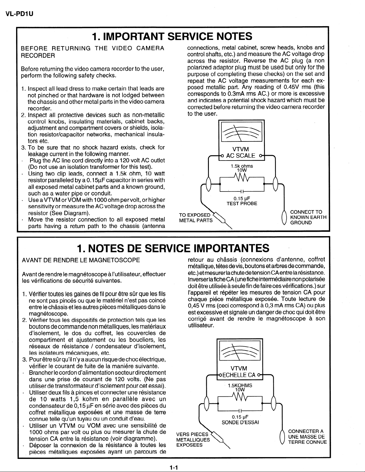
. Using two clip leads, connect a 1.5k ohm, IO watt
resistor paralleled by a 0.15pF capacitor in series with
all exposed metal cabinet parts and a known ground,
such as a water pipe or conduit.
l Use aVTVM or VOM with 1000 ohm pervolt, or higher
sensitivity or measure the AC voltage drop across the
resistor (See Diagram).
l Move the resistor connection to all exposed metal
parts having a return path to the chassis (antenna
connections, metal cabinet, screw heads, knobs and
control shafts, etc.) and measure the AC voltage drop
across the resistor. Reverse the AC plug (a non
polarized adaptor plug must be used but only for the
purpose of completing these checks) on the set and
repeat the AC voltage measurements for each exposed metallic part. Any reading of 0.45V rms (this
corresponds to 0.3mA rms AC.) or more is excessive
and indicates a potential shock hazard which must be
corrected before returning the video camera recorder
to the user.
/
m .
VTVM
0 AC SCALE 0 \
,
’ ~5:ooo~ms
TO EXPOSED
METAL PARTS
;I:“’ E$H
1. NOTES DE SERVICE IMPORTANTES
AVANT DE RENDRE LE MAGNETOSCOPE
Avant de rendre le magnetoscope a I’utilisateur, effectuer
les verifications de securite suivantes.
i
1. Verifier toutes les gaines de fil pour etre sur que les fils
ne sont pas pin&s ou que le materiel n’est pas coin&
entre le chassis et les autres pieces metalliques dans le
magnetoscope.
2. Verifier tous les dispositifs de protection tels que les
boutons de commande non metalliques, les materiaux
d’isolement, le dos du coffret, les couvercles de
compartiment et ajustement ou les boucliers, les
reseaux de resistance / condensateur d’isolement,
les isolateurs mecaniques, etc.
3. Pour etre stir qu’il n’y a aucun risque de choc electrique,
verifier le courant de fuite de la maniere suivante.
. Brancher le cordon d’alimentation secteur directement
dans une prise de courant de 120 volts. (Ne pas
utiliser de transformateur d’isolement pour cet essai).
. Utiliser deux fils a pinces et connecter une rkistance
de 10 watts 1,5 kohm en parallele avec un
condensateur de 0,15 PF en serie avec des pikes du
coffret mbtallique expos6es et une masse de terre
connue telle qu’un tuyau ou un conduit d’eau.
. Utiliser un VTVM ou VOM avec une sensibilitb de
1000 ohms par volt ou plus ou mesurer la chute de
tension CA entre la ksistance (voir diagramme).
. Deposer la connexion de la resistance a toutes les
pieces metalliques exposees ayant un parcours de
.
retour au chassis (connexions d’antenne, coffret
metallique, tetesdevis, boutons et arbres decommande,
etc.) et mesurer lachutede tension CAentre la resistance.
Inverserlafiche6A(uneficheintermediairenonpolaris~e
doit etre utilisee a seule fin de faire ces verifications.) sur
I’appareil et repeter les mesures de tension CA pour
chaque piece metallique exposee. Toute lecture de
0,45 V rms (ceci correspond a 0,3 mA rms CA) ou plus
est excessive et signale un danger de choc qui doit etre
corrige avant de rendre le magn6toscope 3 son
utilisateur.
VTVM
oECHELLE CA 0 \
‘-5%fYMs
METALLIQUES
1-1
Page 3
VL-PDl U
WARNING :TO REDUCETHE RISK OF FIRE OR ELECTRIC SHOCK, DO NOT EXPOSE
THIS APPLIANCE TO WET LOCATIONS.
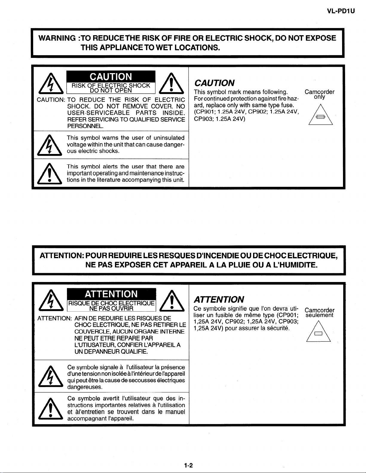
CAUTION: TO REDUCE THE RISK OF ELECTRIC
SHOCK. DO NOT REMOVE COVER. NO
USERSERVICEABLE PARTS INSIDE.
REFER SERVICING TO QUALIFIED SERVICE
PERSONNEL.
This symbol warns the user of uninsulated
voltage within the unit that can cause danger-
A
I
0
A
ous electric shocks.
This symbol alerts the user that there are
important operating and maintenance instruc-
tions in the literature accompanying this unit.
This symbol mark means following. Camcorder
For continued protection against fire haz-
ard, replace only with same type fuse.
(CP901; 1.25A 24V, CP902; 1.25A 24V,
CP903; 1.25A 24V)
only
ATTENTION: POUR REDUIRE LES RESQUES D’INCENDIE OU DE CHOC ELECTRIQUE,
NE PAS EXPOSER CET APPAREIL A LA PLUIE OU A L’HUMIDITE.
A
AA
RISQUE DE CHOC ELECTRIQUE
ATTENTION: AFIN DE REDUIRE LES RISQUES DE
Ce symbole signale a I’utilisateur la presence
d’une tension non isolee a I’interieur de I’appareil
A
1
0
A
qui peut etre la cause de secousses electriques
dangereuses.
Ce symbole avertit I’utilisateur que des instructions importantes relatives a I’utilisation
et al’entretien se trouvent dans le manuel
accompagnant I’appareil.
NE PAS OUVRIR
CHOC ELECTRIQUE, NE PAS RETIRER LE
COUVERCLE, AUCUN ORGANE INTERNE
NE PEUT ETRE REPARE PAR
L’UTIUSATEUR, CONFIER L’APPAREIL A
UN DEPANNEUR QUALIFIE.
0
A
1
0
ATTENTION
Ce symbole signifie que l’on devra utiliser un fusible de meme type (CP901;
1,25A 24V, CP902; 1,25A 24V, CP903;
1,25A 24V) pour assurer la securite.
I
12
Camcorder
seulement
A
Page 4
VL-PDI U
/
/fj CAUTION
BEFORE BATTERY DESTROY
NICKEL-CADMIUM BATTERY
The following program is available in the United States. Please consult local environmental
authorities concerning the availability of this or other programs in your area.
The RBRCTM Seal
SHARP participates in the RBRC
States. The RBRCTM Seal on our battery pack contained in our product indicates that SHARP is
voluntarily participating in an industry program to collect and recycle these batteries. The RBRCTM
program provides you with a convenient alternative to placing spent Nickel-Cadmium battery packs into
the trash or municipal waste stream, which is illegal in some areas. At the end of their useful life, the
Nickel-Cadmium battery can be dropped off at the nearest collection center for recycling. For information
on the nearest collection center, call I-800-8-BATTERY or your local recycling center. If you are located
outside the United States, contact your local authorities for information concerning proper disposal and/
or recycling of this battery. SHARP’s involvement in this program is part of our commitment to protecting
our environment and conserving natural resources.
[Footnote] *RBRCTM is trademark of the Rechargeable Battery Recycling Corporation.
TM* Nickel-Cadmium Battery Recycling Program in the United
NICKEL-METAL HYDRIDE BATTERY
LITHIUM or LITHIUM-ION BATTERY
SEALED LEAD BATTERY
Battery disposal
Contains the above (Rechargeable) Battery. must be recycled or disposed of properly.
Remove the Battery from the products and contact Federal or State Environmental Agencies for
information on recycling and disposal options.
1-3
Page 5
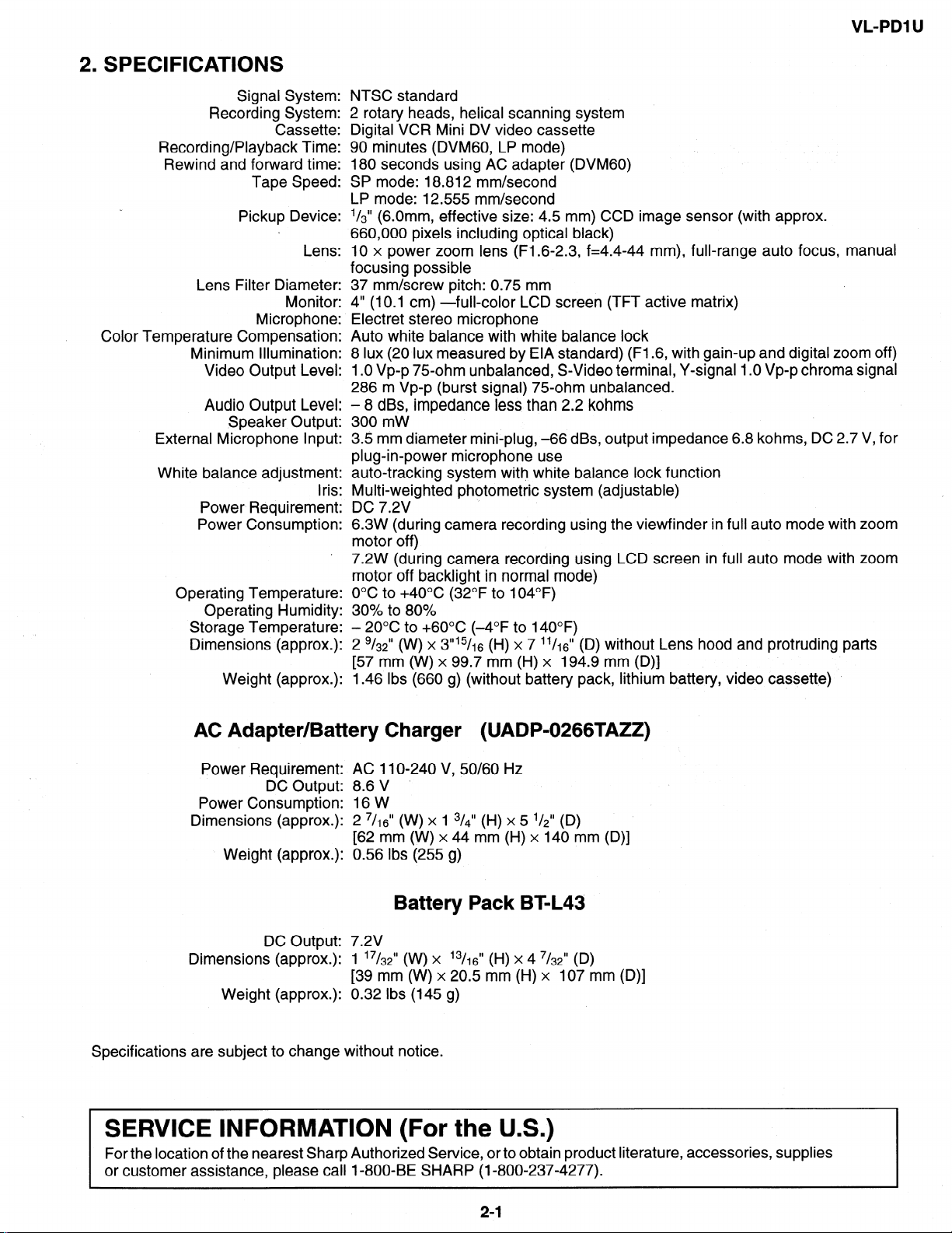
2. SPECIFICATIONS
Signal System:
Recording System:
Cassette:
Recording/Playback Time:
Rewind and forward time:
Tape Speed:
Pickup Device:
Lens:
Lens Filter Diameter:
Monitor:
Microphone:
Color Temperature Compensation:
Minimum Illumination:
Video Output Level:
Audio Output Level:
Speaker Output:
External Microphone input:
White balance adjustment:
Power Requirement;
Power Consumption:
Operating Temperature:
Operating Humidity:
Storage Temperature:
Dimensions (approx.):
Weight (approx.):
NTSC standard
2 rotary heads, helical scanning system
Digital VCR Mini DV video cassette
90 minutes (DVMGO, LP mode)
180 seconds using AC adapter (DVMGO)
SP mode: 18.812 mm/second
LP mode: 12.555 mm/second
l/3” (6 Omm effective size: 4.5 mm) CCD image sensor (with approx.
660,060 pixels including optical black)
10 x power zoom lens (F1.6-2.3, f=4.4-44 mm), full-range auto focus, manual
focusing possible
37 mm/screw pitch: 0.75 mm
4” (10.1 cm) -full-color LCD screen (TFT active matrix)
Electret stereo microphone
Auto white balance with white balance lock
8 lux (20 lux measured by EIA standard) (F1.6, with gain-up and digital zoom off)
1 .O Vp-p 75-ohm unbalanced, S-Video terminal, Y-signal 1 .O Vp-p chroma signal
286 m Vp-p (burst signal) 75-ohm unbalanced.
- 8 dBs, impedance less than 2.2 kohms
300 mW
3.5 mm diameter mini-plug, -66 dBs, output impedance 6.8 kohms, DC 2.7 V, for
plug-in-power microphone use
auto-tracking system with white balance lock function
.
.
ins
Multi-weighted photometric system (adjustable)
DC 7.2V
6.3W (during camera recording using the viewfinder in full auto mode with zoom
motor off)
7.2W (during camera recording using LCD screen in full auto mode with zoom
motor off backlight in normal mode)
O°C to +4O”C (32°F to 104°F)
30% to 80%
- 20°C to +6O”C (-4°F to 140°F)
2 g/& (W) x 3”15/16 (H) x 7 ll/&’ (D) without Lens hood and protruding parts
[57 mm (W) x 99.7 mm (H) x 194.9 mm (D)]
1.46 Ibs (660 g) (without battery pack, lithium battery, video cassette)
AC Adapter/Battery Charger (UADP-0266TAZZ)
Power Requirement:
DC Output:
Power Consumption:
Dimensions (approx.):
Weight (approx.):
AC 11 O-240 V, 50/60 Hz
8.6 v
16W
2 7/,6” (W) x 1 3/~” (H) x 5 ‘/$’ (D)
[62 mm (W) x 44 mm (H) x 140 mm (D)]
0.56 Ibs (255 g)
Battery Pack BT-L43
DC Output:
Dimensions (approx.):
Weight (approx.):
Specifications are subject to change without notice.
7.2V
1 ‘7t32” (w) x ’ 3/, 6” (H) x 4 7/32” (D)
[39 mm (W) x 20.5 mm (H) x 107 mm (D)]
0.32 Ibs (145 g)
SERVICE INFORMATION (For the U.S.)
For the location of the nearest Sharp Authorized Service, or to obtain product literature, accessories, supplies
or customer assistance, please call I-800-BE SHARP (I-800-237-4277).
21
I
Page 6
L-PDl U
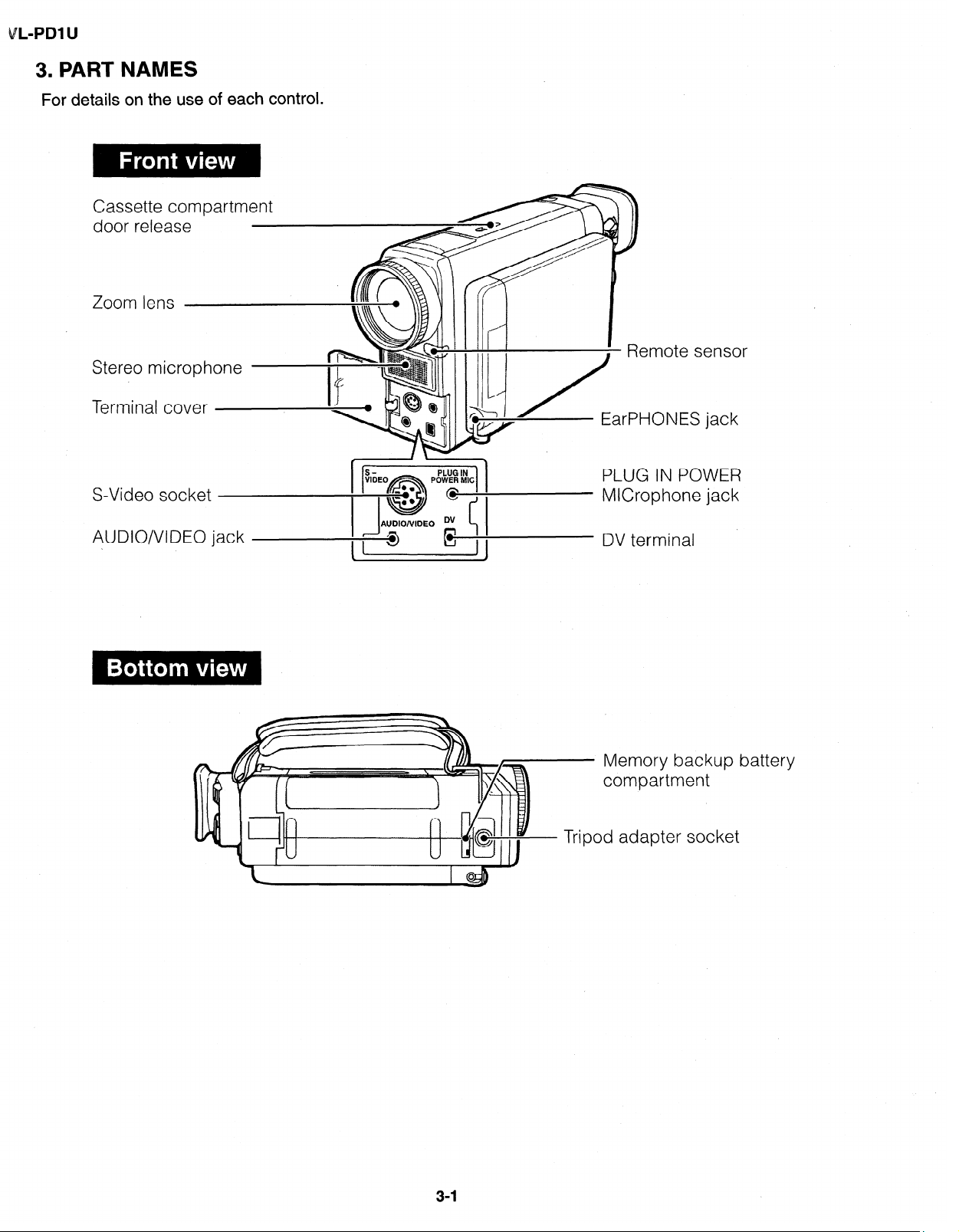
3. PART NAMES
For details on the use of each control.
Cassette compartment
door release
Zoom lens
Stereo microphone
Terminal cover
S-Video socket
AUDIO/VIDEO jack
EarPHONES jack
PLUG IN POWER
MICrophone jack
DV terminal
- Memory backup battery
compartment
Tripod adapter socket
3-l
Page 7
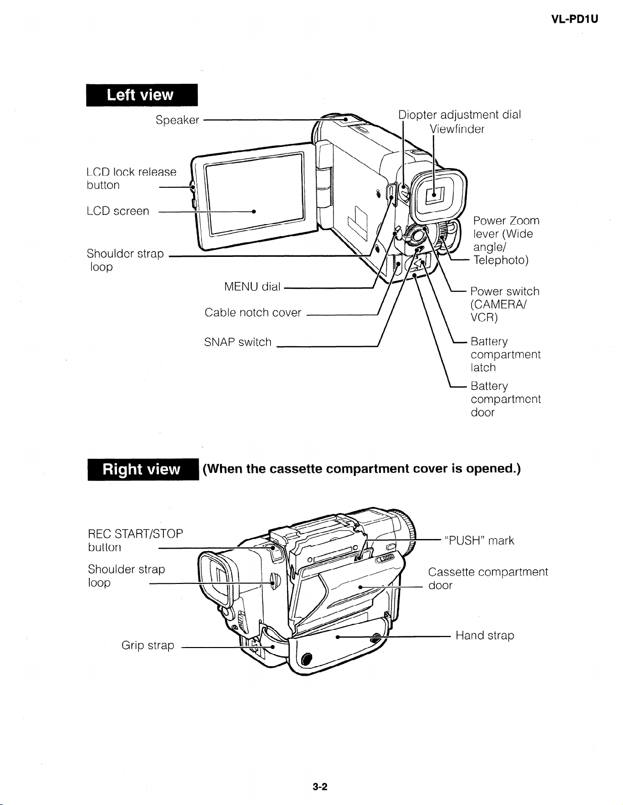
LCD lock release
Cable notch cover
VL-PDl U
Power Zoom
lever (Wide
angle/
Telephoto)
Power switch
(CAMERA/
START/STOP
REC
butto
Shou
loop
SNAP switch
compartment
latch
Battery
compartment
door
(When the cassette compartment cover is opened.)
Cassette compa rtment
32
I
Page 8
VL-PDl U
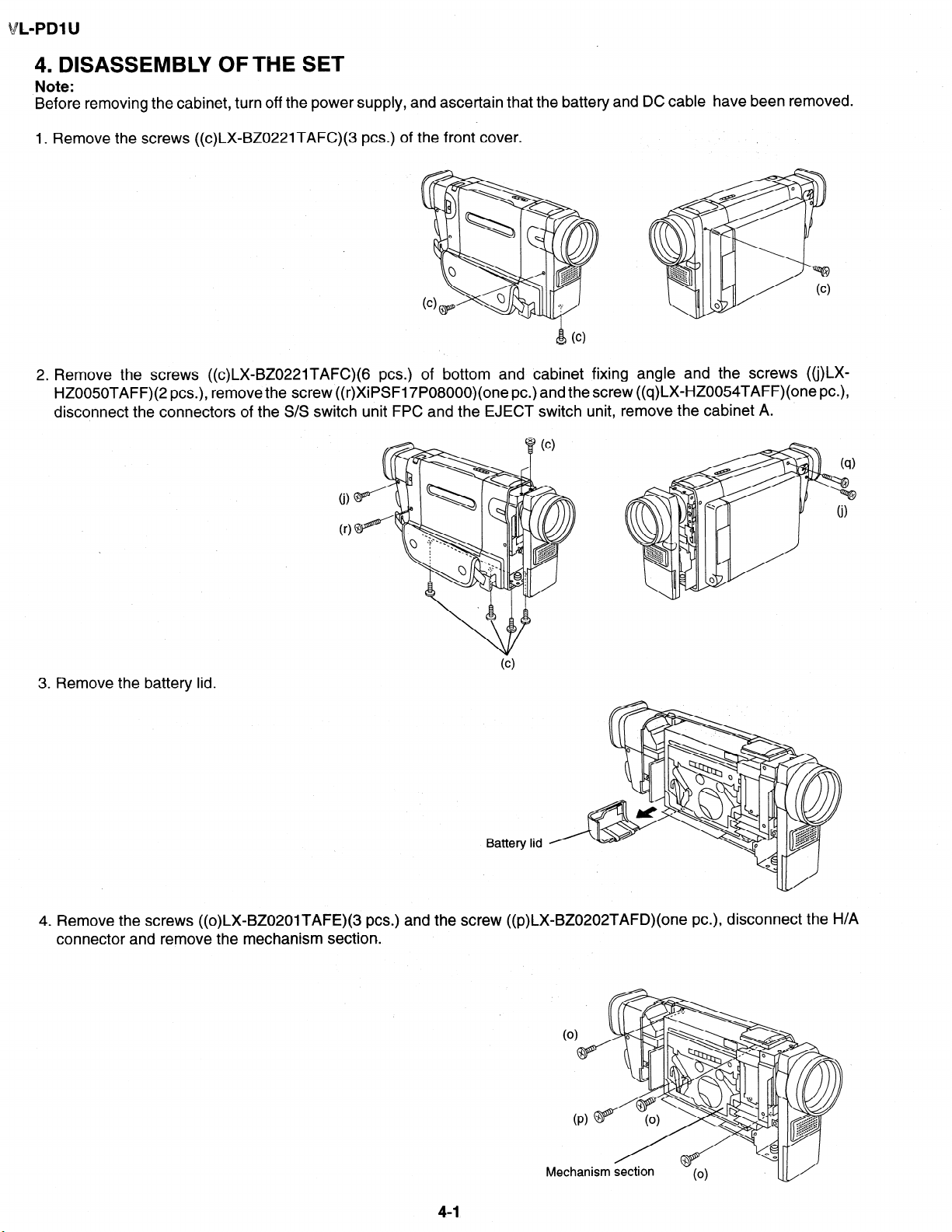
4. DISASSEMBLY OFTHE SET
Note:
Before removing the cabinet, turn off the power supply, and ascertain that the battery and DC cable have been removed.
1. Remove the screws ((c)LX-BZ0221TAFC)(3 PCS.) of the front cover.
2. Remove the screws ((c)LX-BZ0221TAFC)(G PCS.) of bottom and cabinet fixing angle and the screws ((j)LXHZOO50TAFF)(2 PCS.), remove the screw ((r)XiPSF17P08000)(one PC.) and the screw ((q)LX-HZOO54TAFF)(one PC.),
disconnect the connectors of the S/S switch unit FPC and the EJECT switch unit, remove the cabinet A.
.
0)
r
0
3. Remove the battery lid.
Battery lid
4. Remove the screws ((o)LXgBZ0201TAFE)(3 PCS.) and the screw ((p)LX_BZO202TAFD)(one PC.), disconnect the H/A
connector and remove the mechanism section.
4-1
Page 9
VL-PDl U
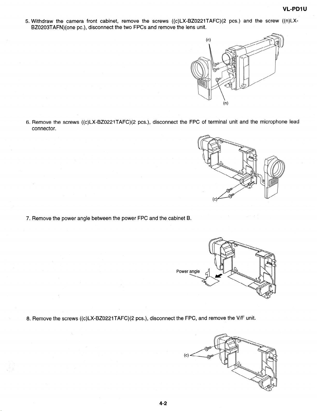
5. Withdraw the camera front cabinet, remove the screws ((c)LX-BZ0221TAFC)(2 PCS.) and the screw ((n)LXBZ0203TAFN)(one PC.), disconnect the two FPCs and remove the lens unit.
6. Remove the screws ((c)LX-BZ022lTAFC)(2 PCS.), disconnect the FPC of terminal unit and the microphone lead
connector.
7. Remove the power angle between the power FPC and the cabinet B.
Power
8. Remove the screws ((c)LX-BZ0221TAFC)(2 PCS.), disconnect the FPC, and remove the V/F unit.
4-2
Page 10
L-PDI u
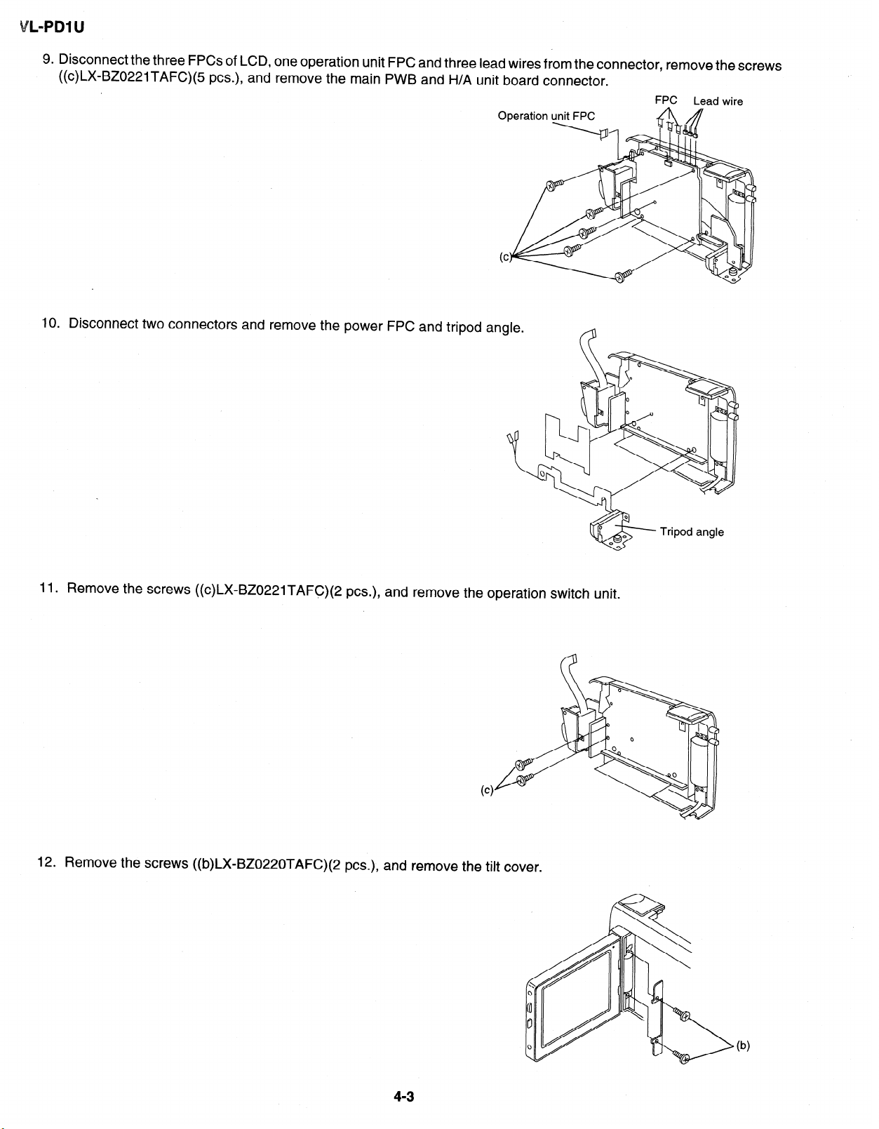
9. Disconnect the three FPCs of LCD, one operation unit FPC and three lead wires from the connector, remove the screws
((c)LX-BZOZ21TAFC)(5 PCS.), and remove the main PWB and H/A unit board connector.
FPC Lead wire
Operation
IO. Disconnect two connectors and remove the power FPC and tripod angle.
unit FPC
11. Remove the screws ((c)LX=BZ0221TAFC)(2 PCS.), and remove the operation switch unit.
12. Remove the screws ((b)LX=BZ0220TAFC)(2 PCS.), and remove the tilt cover.
4-3
Page 11
VL-PDl U
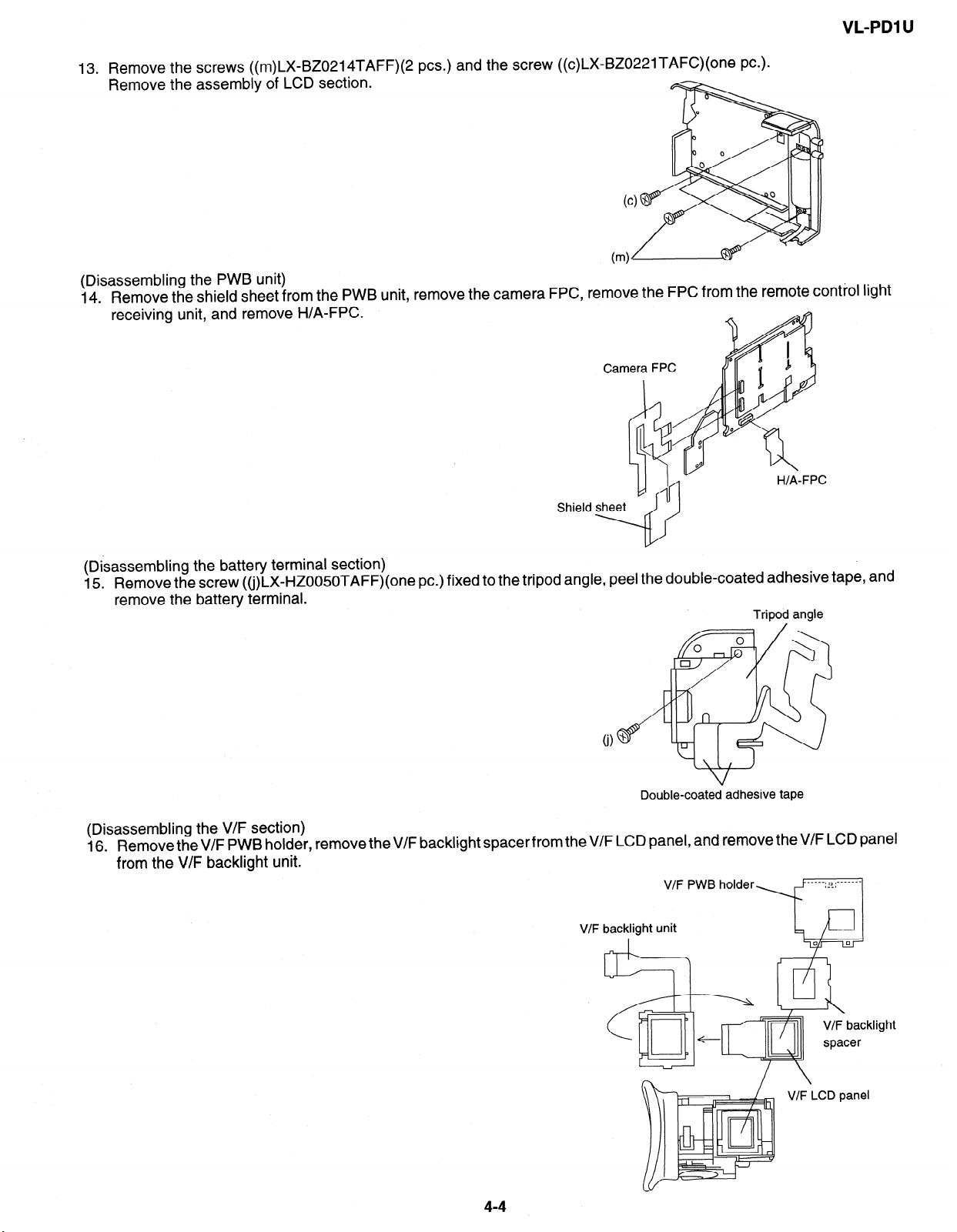
13. Remove the
Remove the
screws ((m)LX-BZ0214TAFF)(2 PCS.) and the screw ((c)LX-BZ0221TAFC)(one PC.).
assembii of LCD section.
(Disassembling the PWB unit)
14. Remove the shield sheet from the PWB unit, remove the camera FPC, remove the FPC from the remote control light
receiving unit, and remove H/A-FPC.
Camera FPC
Shield
(Disassembling the battery terminal section)
Remove the screw ((j)LX-HZOO5OTAFF)(one PC.) fixed to the t
15.
remove the battery terminal.
ripod angle, peel the double-coated adhesive tape,
Tripod angle
Double-coated adhesive tape
and
(Disassembling the V/F section)
16. RemovetheV/F PWB holder, remove theV/F backlight spacerfrom the V/F LCD panel, and remove the V/F LCD panel
from the V/F backlight unit.
V/F PWB holder
V/F backlight unit
I
44
ht
V/F LCD panel
I
Page 12
L-PDl U
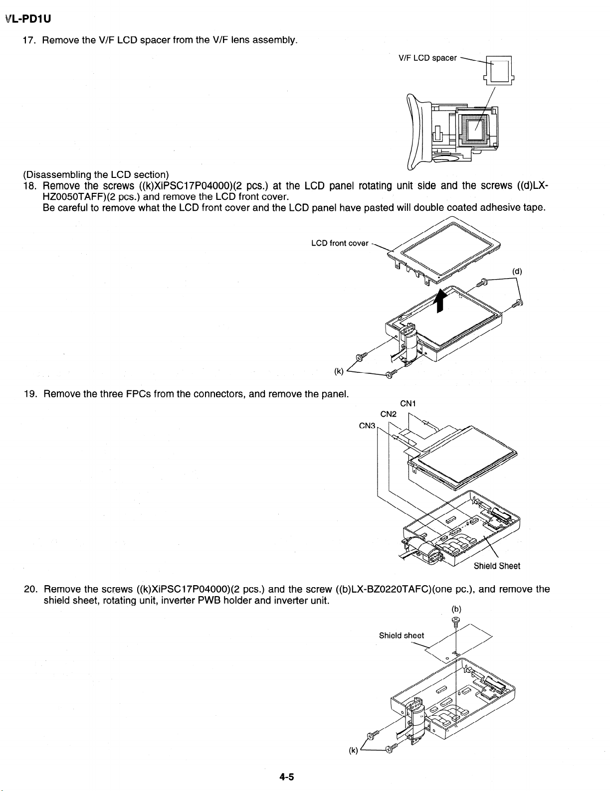
17. Remove the V/F LCD spacer from the V/F lens assembly.
V ‘/F LCD spacer
(Disassembling the LCD section)
18. Remove the screws ((k)XiPSC17P04000)(2 PCS.) at the LCD panel rotating unit side and the screws ((d)LX-
HZ0050TAFF)(2 PCS.) and remove the LCD front cover.
Be careful to remove what the LCD front cover and the LCD panel have pasted will double coated adhesive tape.
LCD
19. Remove the three FPCs from the connectors, and remove the panel.
CN3
20. Remove the screws ((k)XiPSC17P04000)(2 PCS.) and the screw ((b)LX-BZ0220TAFC)(one PC.), and remove the
shield sheet, rotating unit, inverter PWB holder and inverter unit.
(b)
4-5
Page 13
VL-PDl U
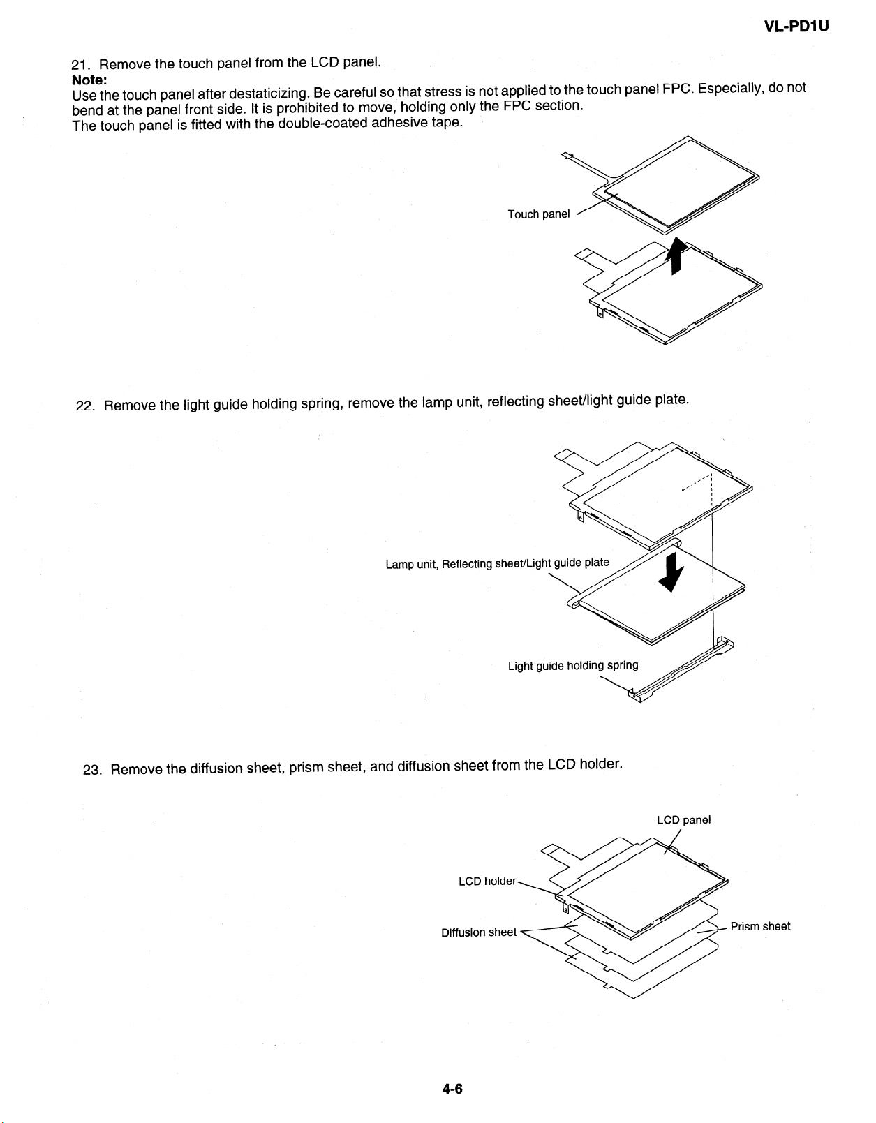
21. Remove the touch panel from the LCD panel.
Note:
Use the touch panel after destaticizing. Be careful so that stress is not applied to the touch panel FPC. Especially, do not
bend at the panel front side. It is prohibited to move, holding only the FPC section.
The touch panel is fitted with the double-coated adhesive tape.
22.
Remove the light guide holding spring, remove the lamp unit, reflecting sheet/light guide plate.
Lamp unit, Reflecting
Light guide holding spring
23. Remove the diffusion sheet, prism sheet, and diffusion sheet from the LCD holder.
LCD holder
Diffusion sheet
LCD panel
Prism sheet
Page 14
L-PDl U
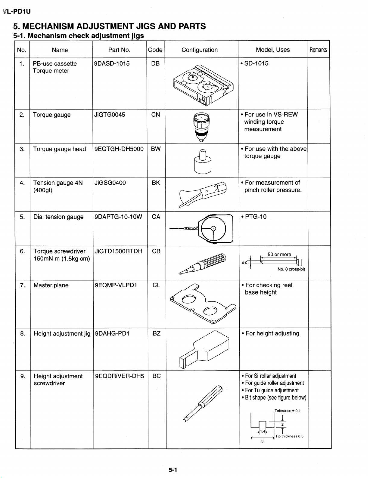
5. MECHANISM ADJUSTMENT JIGS
5-I. Mechanism check adjustment jigs
4 .
Tension gauge 4N
(400gf)
JiGSG0400
AND PARTS
BK
0 r
measurement
\\
l For measurement of
pinch roller pressure.
5.
Dial tension gauge 9DAPTG-1 O-l OW
6 .
Torque screwdriver
JiGTD1500RTDH CB
150mN*m (1.5kgcm)
7.
Master plane SEQMP-VLPDI CL
8 .
Height adjustment jig 9DAHG-PDl
9 .
Height adjustment SEQDRiVER-DH5 BC
screwdriver
1
CA
4 l pTG-‘o
0
0
\
0
BZ
1 I
3
tk
021 \
l For checking reel
50 or more
No. 0 cross-bit
y--
base height
l For height adjusting
l For Si roller adjustment
l For guide roller adjustment
l For Tu guide adjustment
l Bit shape (see figure below)
I
51
Tolerance + 0.1
/’
1 1.4 1 *
b&
Tip thickness 0.5
3
Page 15
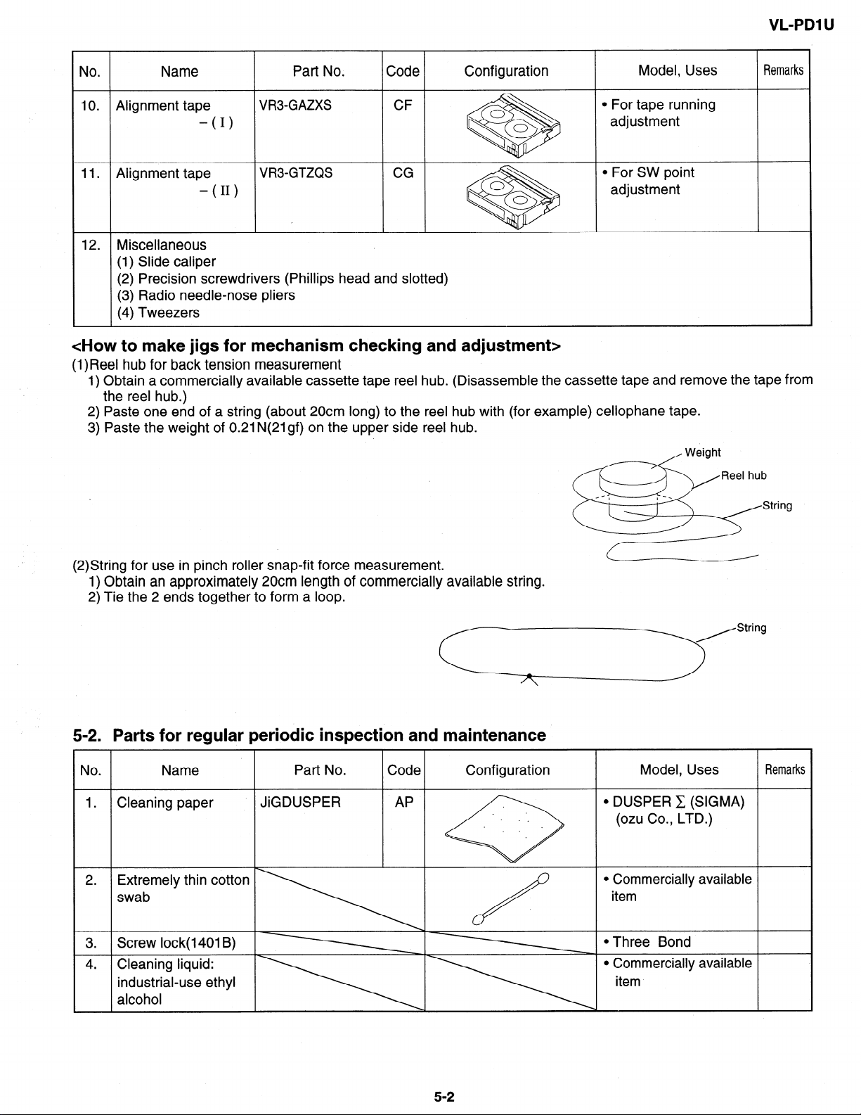
(2) Precision screwdrivers (Phillips head and slotted)
<How to make jigs for mechanism checking and adjustment>
(1)Reel hub for back tension measurement
1) Obtain a commercially available cassette tape reel hub. (Disassemble the cassette tape and remove the tape from
the reel hub.)
2) Paste one end of a string (about 20cm long) to the reel hub with (for example) cellophane tape.
3) Paste the weight of 0.21 N(21 gf) on the upper side reel hub.
VL-PDl U
(2)String for use in pinch roller snap-fit force measurement.
1) Obtain an approximately 20cm length of commercially available string.
2) Tie the 2 ends together to form a loop.
5-2. Parts for regular periodic inspection and maintenance
No . Name
1 . Cleaning paper
2. Extremely thin cotton
swab
. Screw lock( 1401 B)
3
4 . Cleaning liquid:
industrial-use ethyl
alcohol
Part No. Code
JiGDUSPER AP
Configuration
Model, Uses
l DUSPER C (SIGMA)
(ozu Co., LTD.)
l Commercially available
item
l Three Bond
l Commercially available
item
Remarks
5-2
Page 16
VL-PDl U
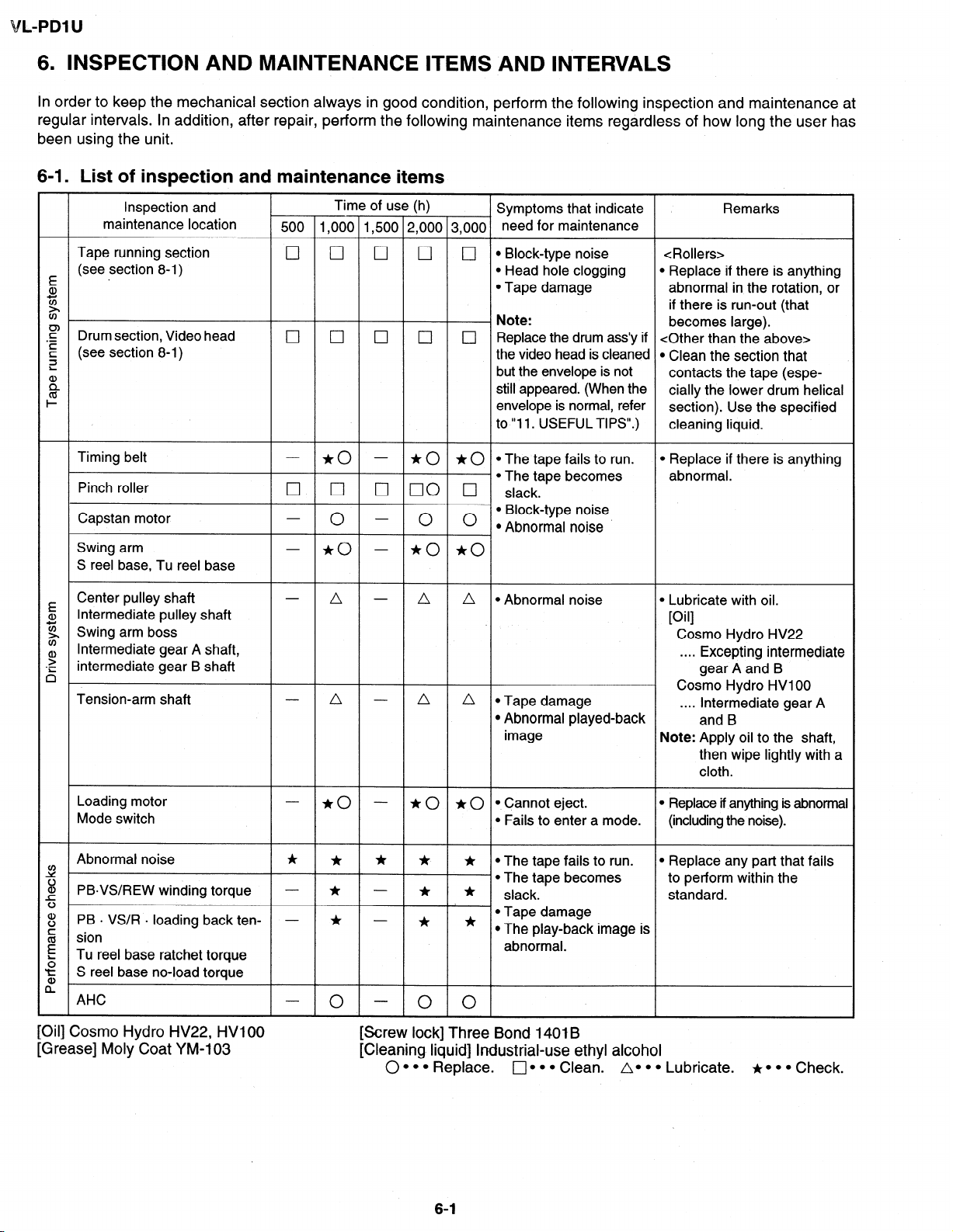
6. INSPECTION AND MAINTENANCE ITEMS ‘AND INTERVALS
In order to keep the mechanical section always in good condition, perform the following inspection and maintenance at
regular intervals. In addition, after repair, perform the following maintenance items regardless of how long the user has
been using the unit.
6-l. List of inspection and maintenance items
Inspection and
maintenance location
Tape running section
(see section 8-1)
E -
a,
5
?Y
F
Drum section, Video head
.-
(see section 8-1)
E
3
:
%
I-
Timing belt
Pinch roller
Capstan motor
Swing arm
S reel base, Tu reel base
E Center pulley shaft
Intermediate pulley shaft
a,
g Swing arm boss
v)
Intermediate gear A shaft,
?
.-
intermediate gear B shaft
6
Tension-arm shaft
Time of use (h)
Symptoms that indicate
500 1,000 1,500 2,000 3,000 need for maintenance
0 cl cl 0
l Block-type noise <Rollers>
0
l Head hole clogging l Replace if there is anything
l Tape damage abnormal in the rotation, or
Note:
17
III 0
c] 0
Replace the drum ass’y if <Other than the above>
the video head is cleaned l Clean the section that
but the envelope is not
still appeared. (When the
envelope is normal, refer
to “11. USEFUL TIPS”.)
- *o -
0 0
0
- *o
* 0 * 0 l The tape fails to run.
l The tape becomes abnormal.
0 00 0
0
slack.
l Block-type noise
0
l Abnormal noise
- *o *o
A - A A *Abnormal noise
A - A A l Tape damage
l Abnormal played-back
image
Remarks
if there is run-out (that
becomes large).
contacts the tape (especially the lower drum helical
section). Use the specified
cleaning liquid.
l Replace if there is anything
l Lubricate with oil.
i
10 11
Cosmo Hydro HV22
. . . .
Excepting intermediate
gear A and B
a
Cosmo Hydro HVIOO
Intermediate gear A
“”
and B
Note: Apply oil to the shaft,
then wipe lightly with a
cloth.
Loading motor
- *o -
Mode switch
Abnormal noise
* * * * * *The tape fails to run.
Y
8
PBVS/REW winding torque - * - * *
5
PB . VS/R l loading back ten- - * - jt *
$
sion
S
E
Tu reel base ratchet torque
;5
‘t
S reel base no-load torque
I?
AHC
[Oil] Cosmo Hydro HV22, HVlOO
[Grease] Moly Coat YM-103
0
[Screw lock] Three Bond 1401B
[Cleaning liquid] Industrial-use ethyl alcohol
* 0 * 0 l Cannot eject.
l Fails to enter a mode. (including the noise).
l The tape becomes to perform within the
slack. standard.
l Tape damage
l The play-back image is
abnormal.
0
0
0 l l l Replace.
I
61
0 l l l Clean. A. l l Lubricate. 1r0 l l Check.
l Replace if anything is abnormal
l Replace any part that fails
Page 17
VL-PDI U
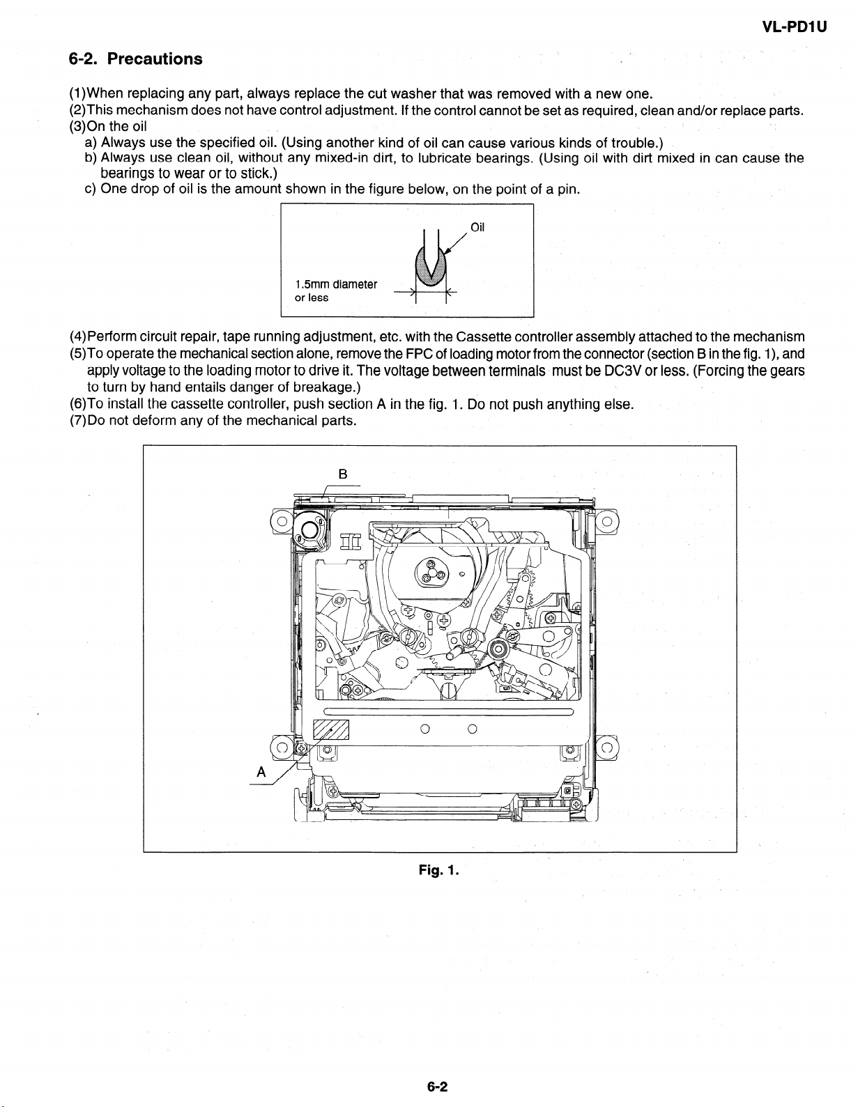
6-2. Precautions
(1)When replacing any part, always replace the cut washer that was removed with a new one.
(2)This mechanism does not have control adjustment. If the control cannot be set as required, clean and/or replace parts.
(3)On the oil
a) Always use the specified oil. (Using another kind of oil can cause various kinds of trouble.)
b) Always use clean oil, without any mixed-in dirt, to lubricate bearings. (Using oil with dirt mixed in can cause the
bearings to wear or to stick.)
c) One drop of oil is the amount shown in the figure below, on the point of a pin.
Oil
,.;g ::::
:::::
.:.:.:
.:y:::.
$$g:.
..:.:.:.:
~~~~~~~~.
;::::::::.
i.......... ..>w.
.>g$g$~ ..:.x.:..
. ..fS...
Y$($.J$Y
1.5mm diameter
or less
(4)Petform circuit repair, tape running adjustment, etc. with the Cassette controller assembly attached to the mechanism
(5)To operate the mechanical section alone, remove the FPC of loading motor from the connector (section B in the fig. l), and
apply voltage to the loading motor to drive it. The voltage between terminals must be DC3V or less. (Forcing the gears
to turn by hand entails danger of breakage.)
(6)To install the cassette controller, push section A in the fig. 1. Do not push anything else.
(7)Do not deform any of the mechanical parts.
‘A:.:.: 8..
N
1
Fig. 1.
6-2
Page 18
L-PDl U
7. MECHANICAL ADJUSTMENTS AND CHECKS .
The items discussed here relate to general on-site servicing (field servicing). Adjustments and replacements that require
sophisticated facilities, jigs and technology are omitted.
In addition, in order to maintain the characteristics that the unit has when it is new, not only are inspection and maintenance
necessary, but it is absolutely necessary that, for example, the tape not be damaged, and always use jigs for adjustments
that require them.
<Precautions>
(1) Always set the power supply and state of the unit as follows for mechanism adjustments and checks.
AC adapter used, with cassette controller assembly 1
07-l Checking the playback (recording) winding torque
07-4 Back tension torque check and adjustment in record (playback) mode
1 AC adapter used, without cassette controller assembly (independent Mechanism) 1
07-2 Checking the rewinding playback (VS-REW) winding torque
DC3V, without cassette controller assembly (Independent Mechanism)
07-3 Checking of reel base height
07-5 Checking and adjustment of tension roller position in record (playback) mode
07-6 Checking of supply S reel base no-load torque
07-7 Checking of loading back tension
07-8 Checking of winding Tu reel base ratchet torque
07-9 Checking of rewinding playback (VS-REW) back tension
l 7-10 Checking of pinch pressing force
(2) When performing checks with a DC3V power supply and independent mechanism, disconnect the loading motor
FPC from the connector.
(3) Always run the tape with the cassette controller assembly attached.
7-1. Checking the ptayback (recording) winding torque
(l)Set the torque cassette with the cassette controller assembly attached, then, in SP recording mode (playback mode
if a signal has already been recorded in SP mode on the tape), confirm that the torque on the winding side is within the
standard.
Winding torque standard-in record (playback) mode
0.70 * 0.35mNm (7.0 + 3.5gfcm),
ripple 0‘.2mN*m (2gfcm) or less
(If there is torque ripple, read the center value.)
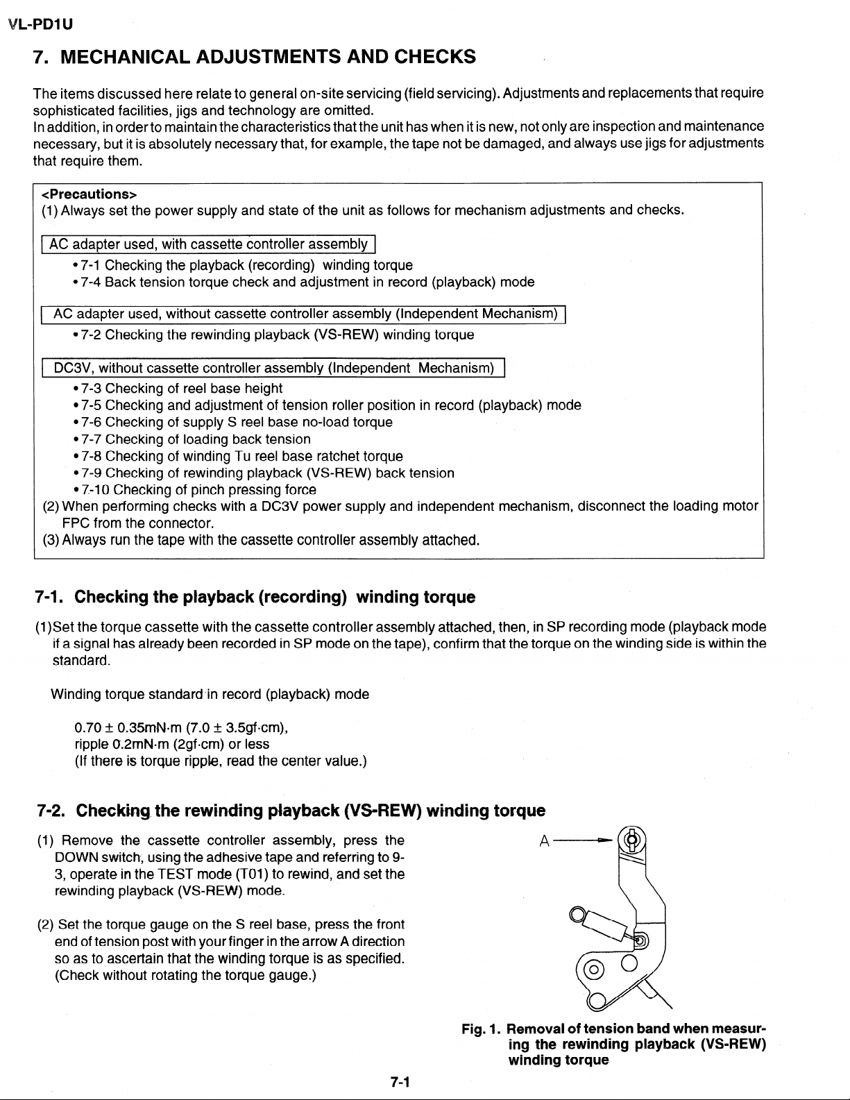
7-2. Checking. the rewinding playback (VS-REW) winding torque
(1) Remove the cassette controller assembly, press the
DOWN switch., using the adhesive tape and referring to 9-
3, operate in the TEST mode (TOl) to rewind, and set the
rewinding playback (VS-REW) mode.
(2) Set the torque gauge on the S reel base, press the front
end of tension post with your finger in the arrow A direction
so as to ascertain that the winding torque is as specified.
(Check without rotating the torque gauge.)
7-l
Fig. 1.
Removal of tension band when measur-
ing the rewinding playback (VS-REW)
winding torque
Page 19
VL-PDI U
Rewinding playback (VS-REW) winding torque standard
1.6 + O.GmN=m (16 + Ggfcm),
ripple 0.4mN*m (4gfcm) or less
(If torque ripple exists, read its center value.)
(3) After checking the winding torque remove the torque gauge, and remove the adhesive tape used in item (1) above (refer
to 9-3). The STANDBY mode is set automatically.
7-3. Checking of reel base height
(l)Remove the cassette controller assembly (refer to 9-2).
(2)Referring to 9-1, apply DC3V to the loading motor and put the system into playback mode.
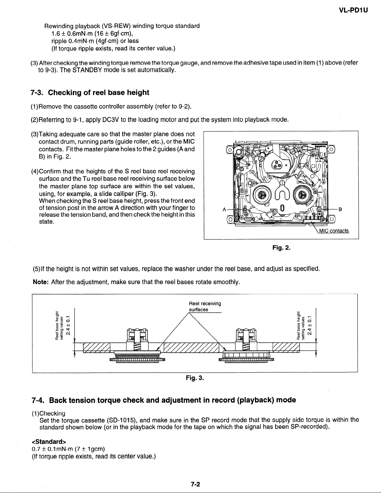
(3)Taking adequate care so that the master plane does not
contact drum, running parts (guide roller, etc.), or the MIC
contacts. Fit the master plane holes to the 2 guides (A and
B) in Fig. 2.
(4)Confirm that the heights of the S reel base reel receiving
surface and the Tu reel base reel receiving surface below
the master plane top surface are within the set values,
using, for example, a slide calliper (Fig. 3).
When checking the S reel base height, press the front end
of tension post in the arrow A direction with your finger to
release the tension band, and then check the height in this
state.
B
tacts
Fig. 2.
(5)lf the height is not within set values, replace the washer under the reel base, and adjust as specified.
Note: After the adjustment, make sure that the reel bases rotate smoothly.
Reel receiving
Fig. 3.
7-4. Back tension torque check and adjustment in record. (playback) mode
(1)Checking
Set the torque cassette (SD-1015), and make sure in the SP record mode that the supply side torque is within the
standard shown below (or in the playback mode for the tape on which the signal has been SP-recorded).
<Standard>
0.7 + 0.1 mN*m (7 + lgcm)
(If torque ripple exists, read its center value.)
7-2
Page 20
L-PDl U
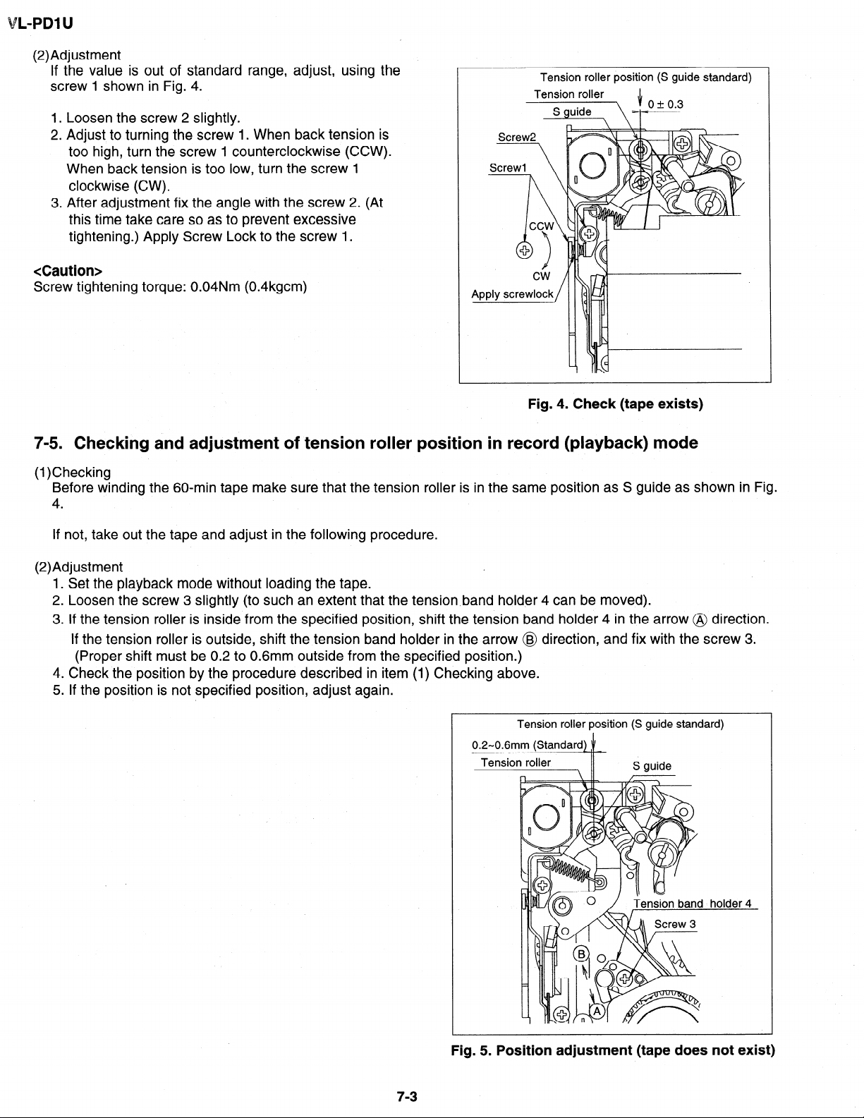
(2)Adjustment
If the value is out of standard range, adjust, using the
screw 1 shown in Fig. 4.
1. Loosen the screw 2 slightly.
2. Adjust to turning the screw 1. When back tension is
too high, turn the screw 1 counterclockwise (CCW).
When back tension is too low, turn the screw 1
clockwise (CW).
3. After adjustment fix the angle with the screw 2. (At
this time take care so as to prevent excessive
tightening.) Apply Screw Lock to the screw 1.
<Caution>
Screw tightening torque: 0.04Nm (0.4kgcm)
Tension roller position (S guide standard)
Tension roller ,I,
Fig. 4. Check (tape exists)
7-5. Checking and adjustment of tension roller position in record (playback) mode
(1)Checking
Before winding the 60-min tape make sure that the tension roller is in the same position as S guide as shown in Fig.
4.
If not, take out the tape and adjust in the following procedure.
(2)Adjustment
1.
Set the playback mode without loading the tape.
2.
Loosen the screw 3 slightly (to such an extent that the tensionband holder 4 can be moved).
3.
If the tension roller is inside from the specified position, shift the tension band holder 4 in the arrow @ direction.
If the tension roller is outside, shift the tension band holder in the arrow @ direction, and fix with the screw 3.
(Proper shift must be 0.2 to 0.6mm outside from the specified position.)
4
Check the position by the procedure described in item (1) Checking above.
5:
If the position is not specified position, adjust again.
Tension roller position (S guide standard)
7-3
Fig. 5. Position adjustment (tape does not exist)
Page 21
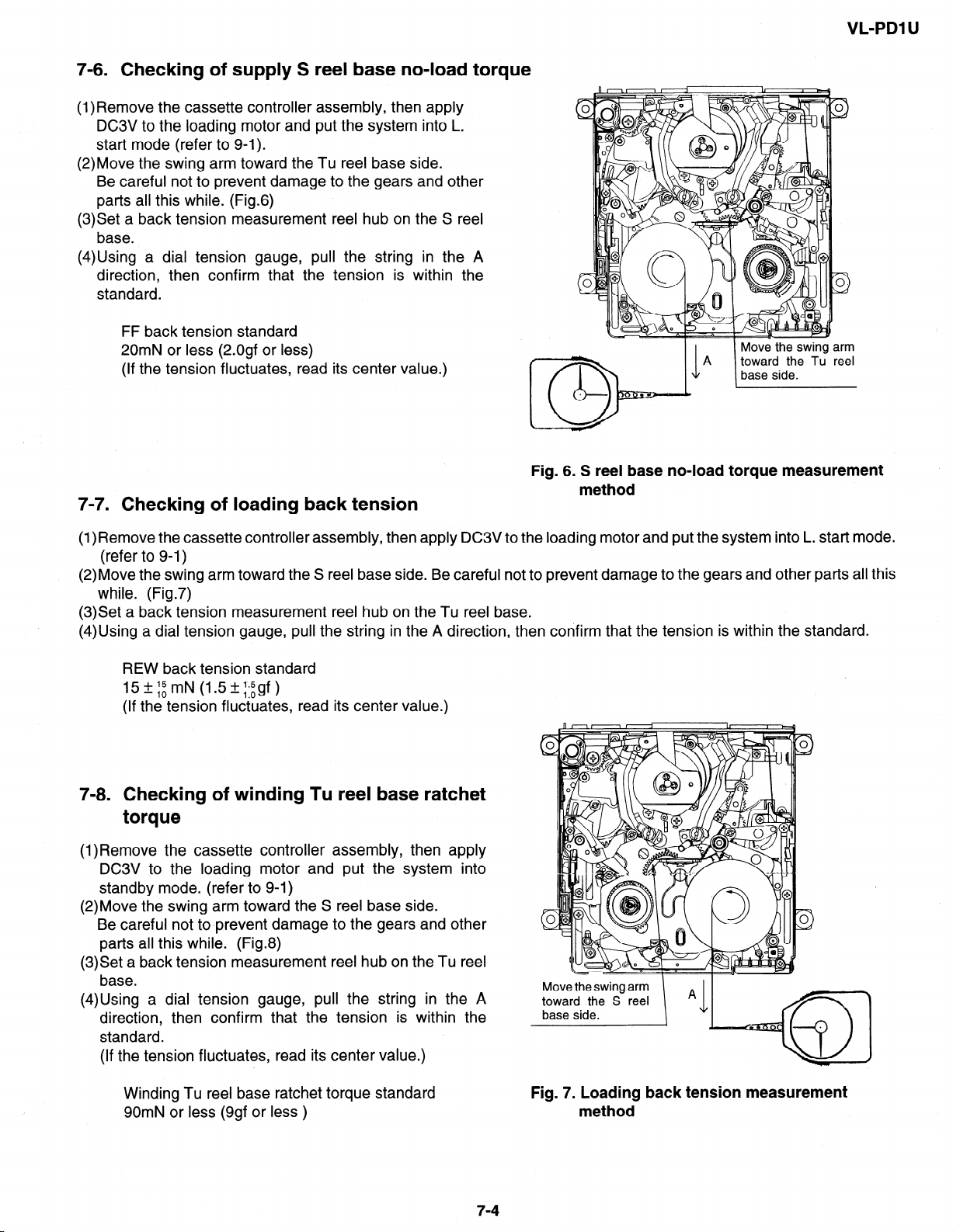
7-6. Checking of supply S reel base no-load torque
(l)Remove the cassette controller assembly, then apply
DC3V to the loading motor and put the system into L.
start mode (refer to 9-l).
(2)Move the swing arm toward the Tu reel base side.
Be careful not to prevent damage to the gears and other
parts all this while. (Fig.6)
(3)Set a back tension measurement reel hub on the S reel
base.
(4)Using a dial tension gauge, pull the string in the A
direction, then confirm that the tension is within the
standard.
FF back tension standard
20mN or less (2.0gf or less)
(If the tension fluctuates, read its center value.)
7-7. Checking of loading back tension
VL-PDI U
Fig. 6. S reel base no-load torque measurement
method
(l)Remove the cassette controller assembly, then apply DC3V to the loading motor and put the system into L. start mode.
(refer to 9-1)
(2)Move the swing arm toward the S reel base side. Be careful not to prevent damage to the gears and other parts all this
while. (Fig.7)
(3)Set a back tension measurement reel hub on the Tu reel base.
(4)Using a dial tension gauge, pull the string in the A direction, then confirm that the tension is within the standard.
REW back tension standard
lSfi:rnN (l+.;gf)
(If the tension fluctuates, read its center value.)
7-8. Checking of winding Tu reel base ratchet
torque
(l)Remove the cassette controller assembly, then apply
DC3V to the loading motor and put the system into
standby mode. (refer to 9-l)
(2)Move the swing arm toward the S reel base side.
Be careful not to.prevent damage to the gears and other
parts all this while. (Fig.8)
(3)Set a back tension measurement reel hub on the Tu reel
base.
(4)Using a dial tension gauge, pull the string in the A
direction, then confirm that the tension is within the
standard.
(If the tension fluctuates, read its center value.)
Move the swing arm
toward the S reel
base side.
Winding Tu reel base ratchet torque standard
90mN or less (9gf or less )
Fig. 7. Loading back tension measurement
method
7-4
Page 22
VL-PDl U
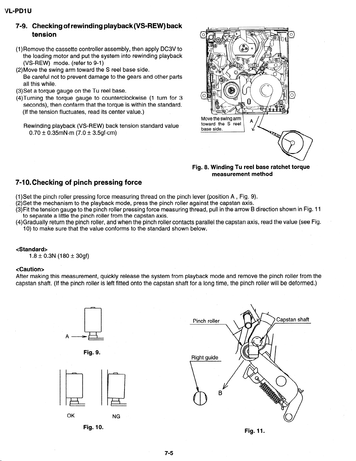
7-9. Checking of rewinding playback(VS-REW) back
tension
(1) Remove the cassette controller assembly, then apply DC3V to
the loading motor and put the system into rewinding playback
(VS-REW) mode. (refer to 9-l)
(2)Move the swing arm toward the S reel base side.
Be careful not to prevent damage to the gears and other parts
all this while.
(3)Set a torque gauge on the Tu reel base.
(4)Turning the torque gauge to counterclockwise
seconds), then confarm that the torque is within
(If the tension fluctuates, read its center value.)
Rewinding playback (VS-REW) back tension standard value
0.70 + 0.35mN*m (7.0 + 3Sgfcm)
(1 turn for 3
the standard.
7-lO.Checking of pinch pressing force
Fig. 8. Winding Tu reel base ratchet torque
measurement method
(l)Set the pinch roller pressing force measuring thread on the pinch lever (position A , Fig. 9).
(2)Set the mechanism to the playback.mode, press the pinch roller against the capstan axis.
(3)Fit the tension gauge to the pinch roller pressing force measuring thread, pull in the arrow B direction shown in Fig. 11
to separate a little the pinch roller from the capstan axis.
(4)Gradually return the pinch roller, and when the pinch roller contacts parallel the capstan axis, read the value (see Fig.
10) to make sure that the value conforms to the standard shown below.
<Standard>
1.8 + 0.3N (180 + 30gf)
<Caution>
After making this measurement, quickly release the system from playback mode and remove the pinch roller from the
capstan shaft. (If the pinch roller is left fitted onto the capstan shaft for a long time, the pinch roller will be deformed.)
A-
Fig. 9.
OK
Fig. 10.
NG
Fig. 11.
7-5
Page 23
VL-PDI U
8. TAPE RUNNING ADJUSTMENT
8-1 m Adjustment locations
I I
<Replacement parts>
. S guide
. T roller, arm
- Tu guide, arm
- Slide chassis
Adjust the height of only
replaced parts with the
adjusting jig.
Adjustment procedure 8-2
-
Cassette controller
installation
3
. Ball base
- Guide roller
. Drum assembly
- Cap motor, etc.
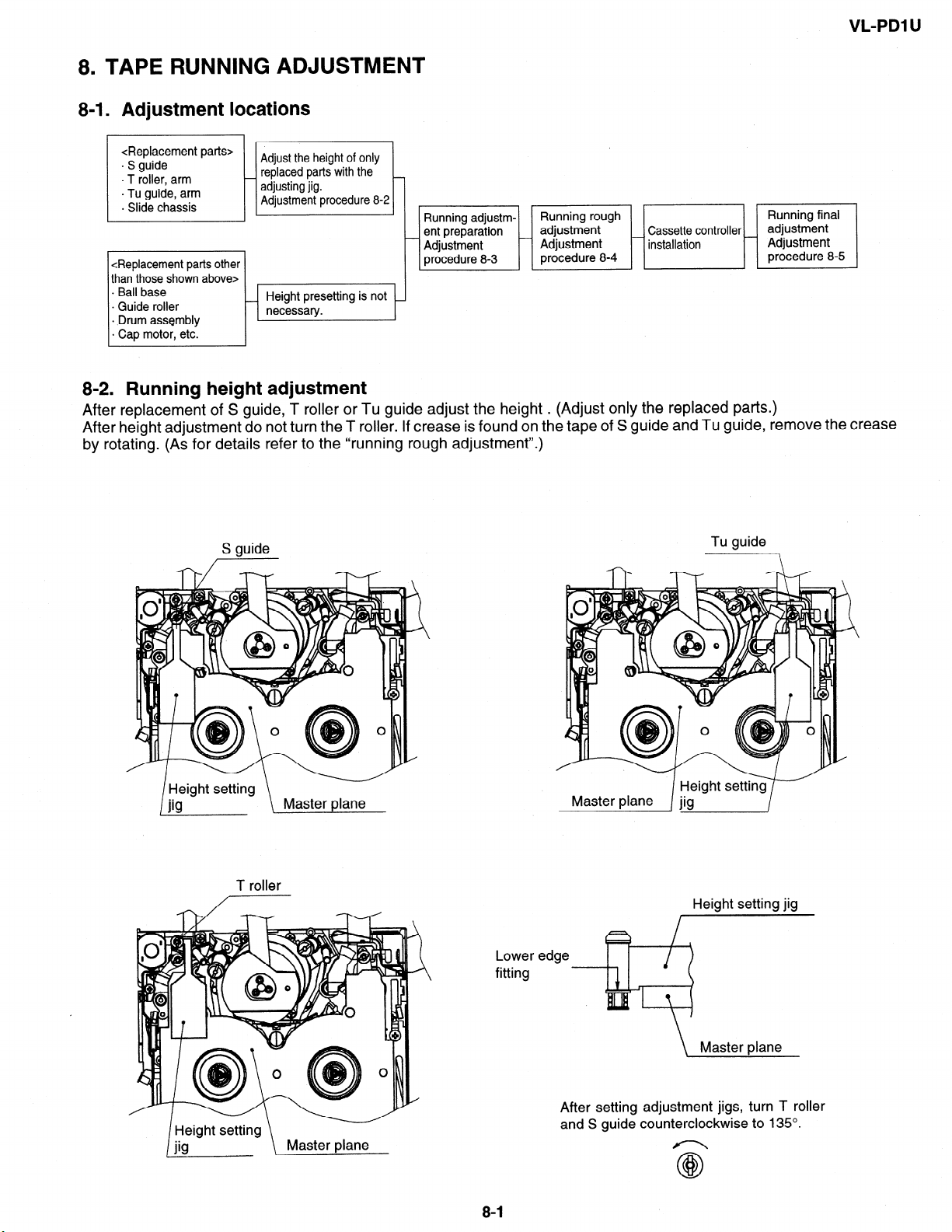
8-2. Running height adjustment
After replacement of S guide, T roller or Tu guide adjust the height . (Adjust only the replaced parts.)
After height adjustment do not turn the T roller. If crease is found on the tape of S guide and Tu guide, remove the crease
by rotating. (As for details refer to the “running rough adjustment”.)
S guide
/
Tu guide
T roller
Height setting jig
Lower edge
fitting
\ Master plane
After setting adjustment jigs, turn T roller
and S guide counterclockwise to 135’.
Page 24
VL-PDl U
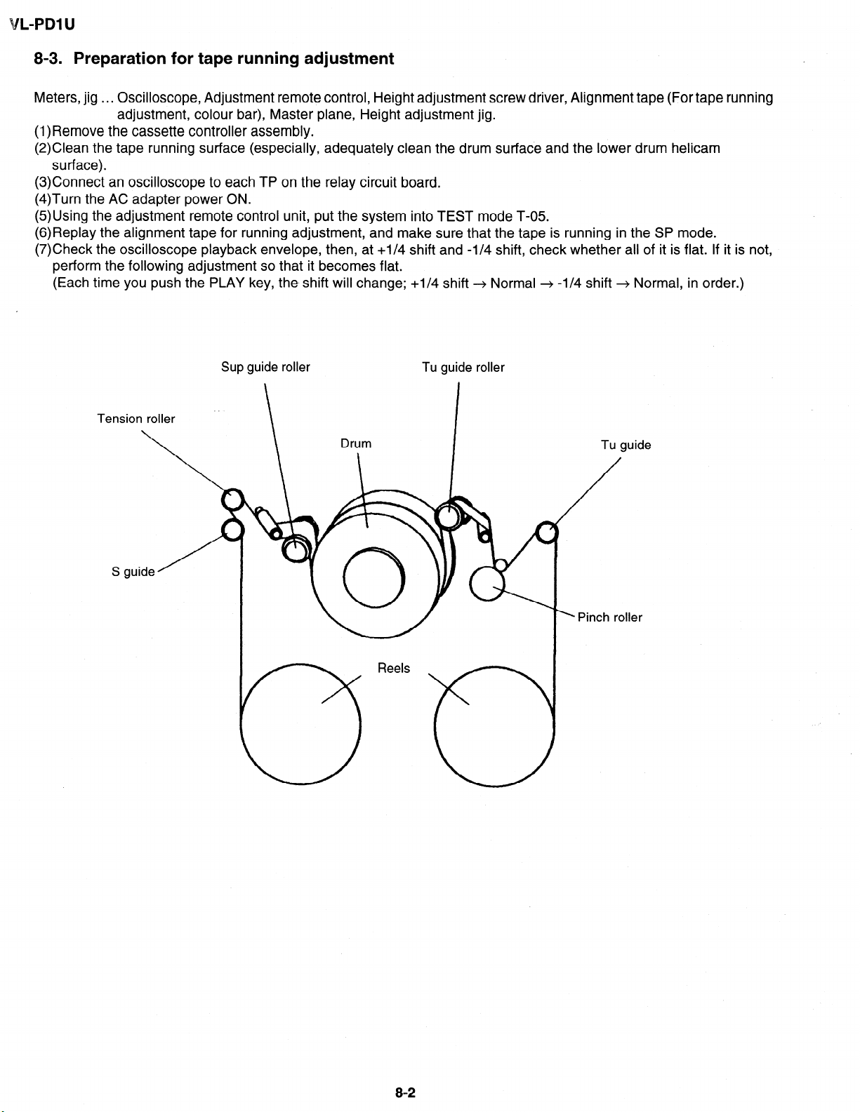
8-3. Preparation for tape running adjustment
Meters, jig . . . Oscilloscope, Adjustment remote control, Height adjustment screw driver, Alignment tape (For tape running
adjustment, colour bar), Master plane, Height adjustment jig.
(1)Remove the cassette controller assembly.
(2)Clean the tape running surface (especially, adequately clean the drum surface and the lower drum helicam
surface).
(3)Connect an oscilloscope to each TP on the relay circuit board.
(4)Turn the AC adapter power ON.
(5)Using the adjustment remote control unit, put the system into TEST mode T-05.
(6)Replay the alignment tape for running adjustment, and make sure that the tape is running in the SP mode.
(7)Check the oscilloscope playback envelope, then, at +I/4 shift and -l/4 shift, check whether all of it is flat. If it is not,
perform the following adjustment so that it becomes flat.
(Each time you push the PLAY key, the, shift will change; +I/4 shift -+ Normal + -l/4 shift --+ Normal, in order.)
Sup guide roller
Tu guide roller
Tu guide
8-2
Page 25
VL-PDl U
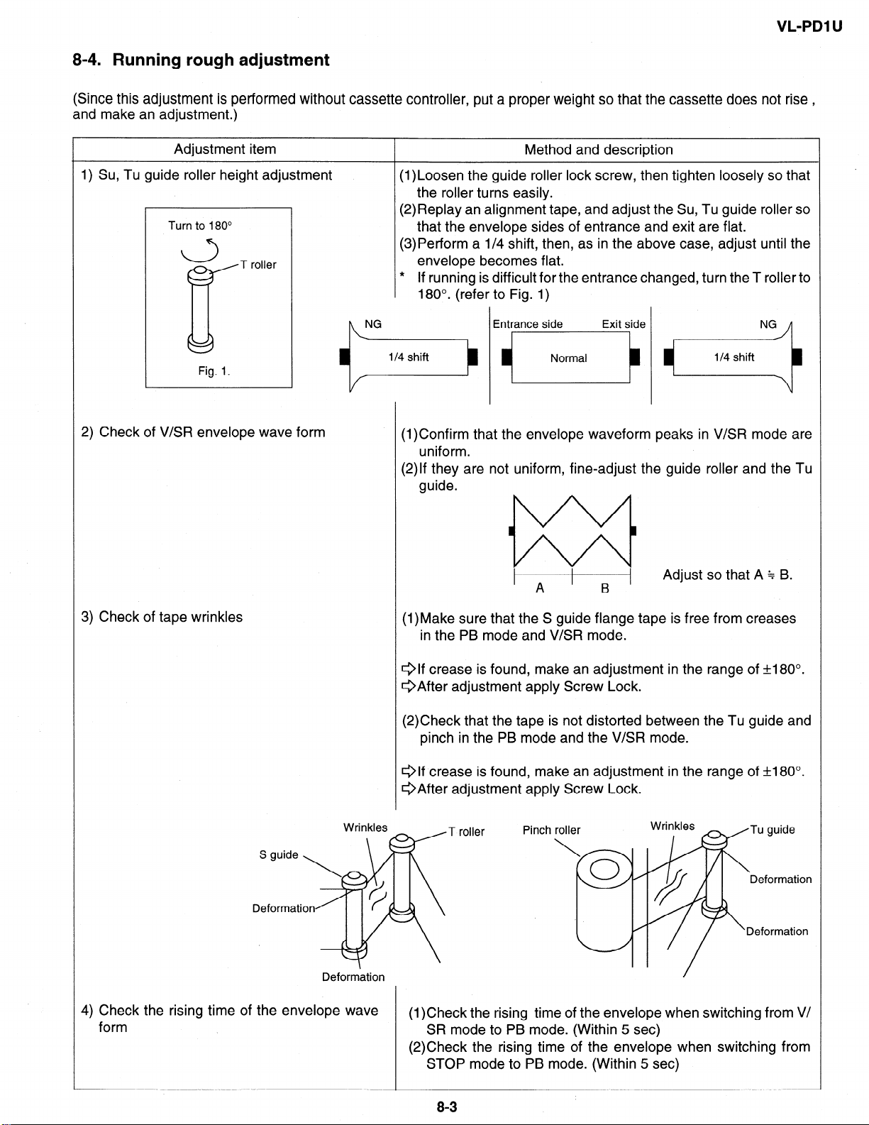
8-4. Running rough adjustment
(Since this adjustment is performed without cassette controller, put a proper weight so that the cassette does not rise ,
and make an adjustment.)
Adjustment item
1) Su, Tu guide roller height adjustment
Turn to 180”
a
c
2) Check of V&R envelope wave form
T roller
Method and description
(l)Loosen the guide roller lock screw, then tighten loosely so that
the roller turns easily.
(2)Replay an alignment tape, and adjust the Su, Tu guide roller so
that the envelope sides of entrance and exit are flat.
(3)Perform a l/4 shift, then, as in the above case, adjust until the
envelope becomes flat.
* If running is difficult for the entrance changed, turn the T roller to
180”. (refer to Fig. 1)
(l)Confirm that the envelope waveform peaks in V/SR mode are
uniform.
(2)lf they are not uniform, fine-adjust the guide roller and the Tu
guide.
3) Check of tape wrinkles
Deformation
1
A
(l)Make sure that the S guide flange tape is free from creases
in the PB mode and V/SR mode.
elf crease is found, make an adjustment in the range of f180°.
@After adjustment apply Screw Lock.
(2)Check that the tape is not distorted between the Tu guide and
pinch in the PB mode and the V/SR mode.
Qlf crease is found, make an adjustment in the range of t180”.
QAfter adjustment apply Screw Lock.
T roller
Pinch roller
\
B
0
Adjust so that A $ B.
Wrinkles
Tu guide
Deformation
//
~
‘q // ‘Deformation
4) Check the rising time of the envelope wave
form
(1)Check the rising time of the envelope when switching from V/
SR mode to PB mode. (Within 5 set)
(2)Check the rising time of the envelope when switching from
STOP mode to PB mode. (Within 5 set)
I
83
Page 26
L-PDl U
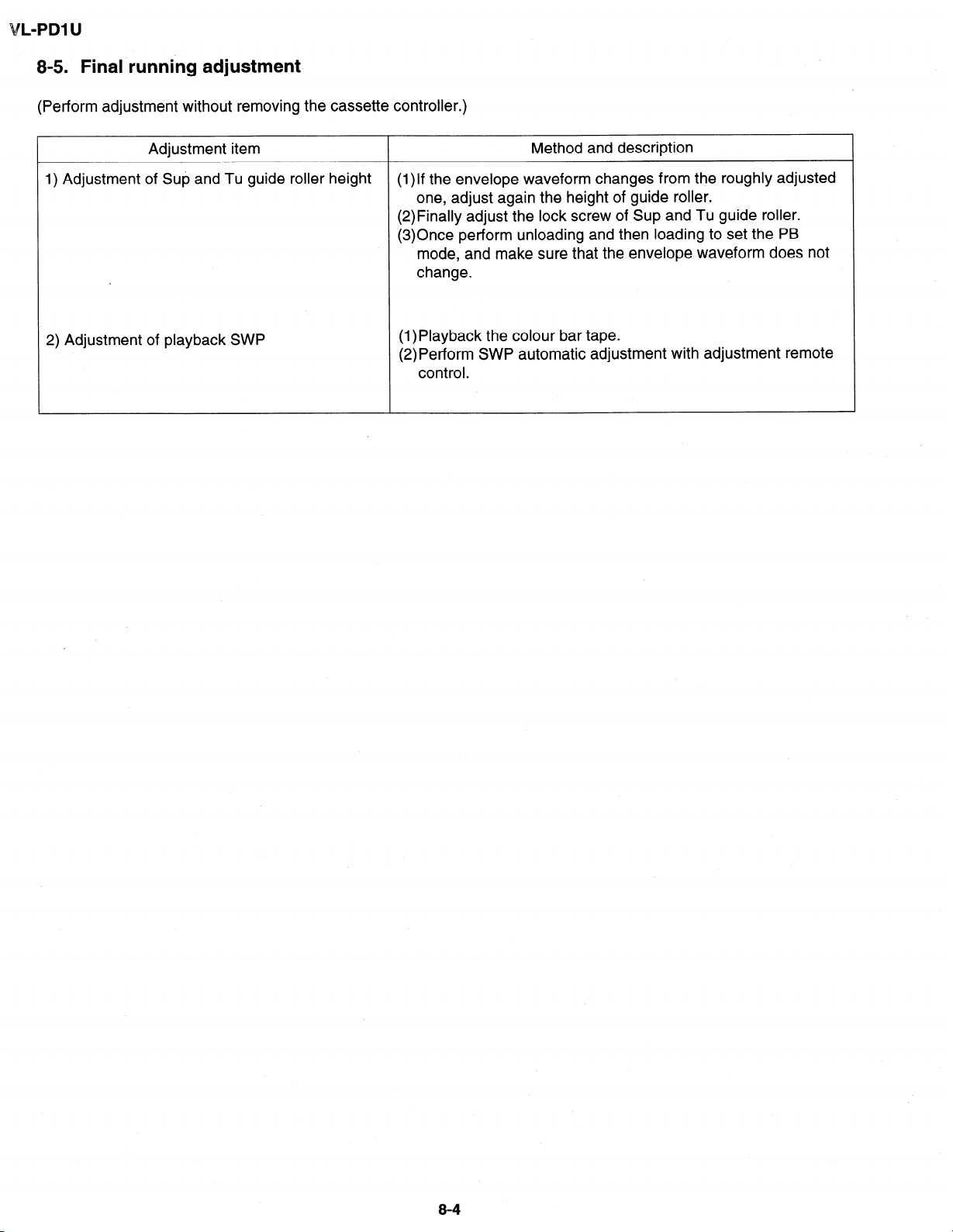
8-5. Final running adjustment
(Perform adjustment without removing the cassette controller.)
Adjustment item
1) Adjustment of Sup and Tu guide roller height
2) Adjustment of playback SWP
Method and description
(1)lf the envelope waveform changes from the roughly adjusted
one, adjust again the height of guide roller.
(2)Finally adjust the lock screw of Sup and Tu guide roller.
(3)Once perform unloading and then loading to set the PB
mode, and make sure that the envelope waveform does not
change.
(1)Playback the colour bar tape.
(2) Perform SWP automatic adjustment with adjustment remote
control.
8-4
Page 27
9. MECHANICAL SECTION ASSEMBLY AND PARTS REPLACEMENT
(DISASSEMBLY AND REASSEMBLY)
Mechanical section disassembly and reassembly are explained in this section.
For removal of the cabinet, etc., refer to 4. DISASSEMBLY OF THE SET.
<Precautions>
1. Always replace cut washers that have been removed, for example in parts replacement, with new ones.
2. When reassembling, be careful not to allow screws, washers or foreign matter to enter. They can cause mechanical
misoperation.
3. Use the cleaning liquid, oil, grease and screw lock that are specified below. Use of any other kind can cause
mechanical misoperation.
.
l
011
Grease:
Screw lock: Three Bond :1401B
Cleaning liquid: Industrial-use ethyl alcohol
4. Turn the mechanical section over, do not place it on, for example, a desk. Deformation and scratching of mechanical
parts can cause trouble.
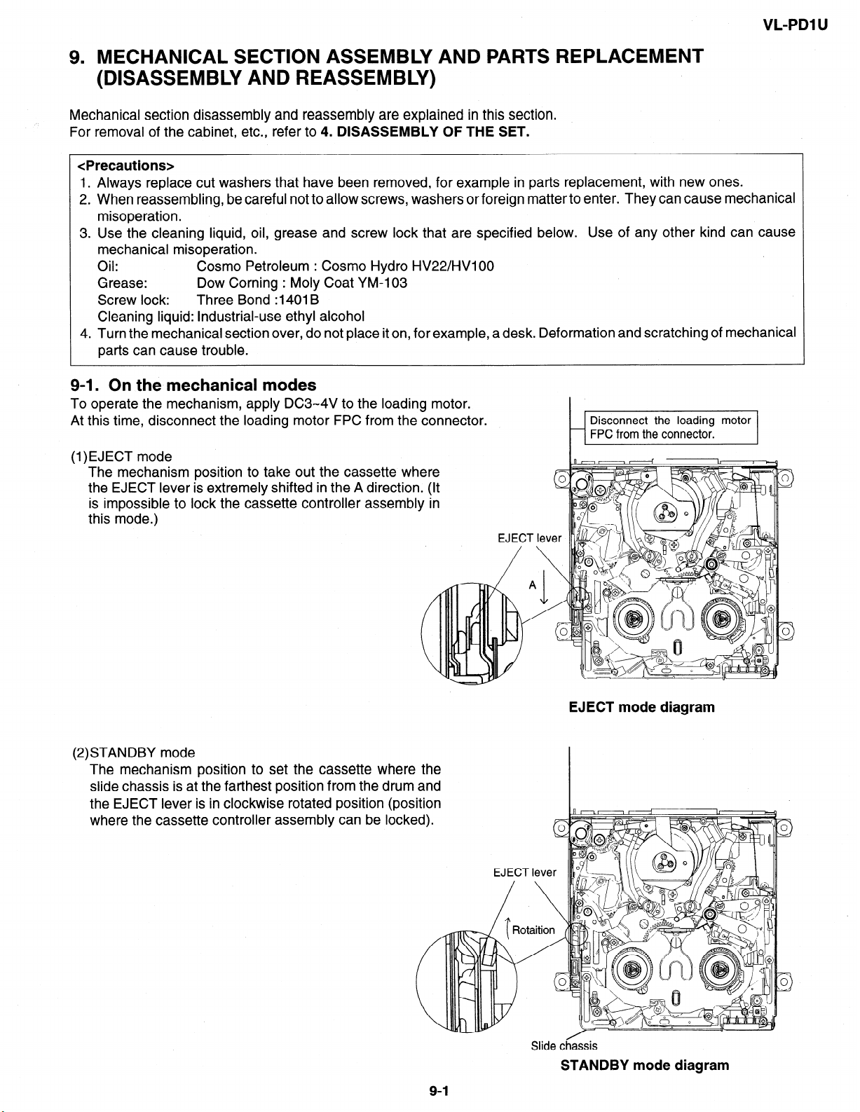
9-I. On the mechanical modes
To operate the mechanism, apply DC3-4V to the loading motor.
At this time, disconnect the loading motor FPC from the connector.
Cosmo Petroleum : Cosmo Hydro HV22/HVlOO
Dow Corning : Moly Coat YM-103
VL-PDl U
(l)EJECT mode
The mechanism position to take out the cassette where
the EJECT lever is extremely shifted in the A direction. (It
is impossible to lock the cassette controller assembly in
this mode.)
(2)STANDBY mode
The mechanism position to set the cassette where the
slide chassis is at the farthest position from the drum and
the EJECT lever is i
where the cassette controller assembly can be
n clockwise rotated position
(position
EJEC
T lev
\
EJECT mode diagram
0
3
Slide chassis
STANDBY mode diagram
Page 28
L-PDl U
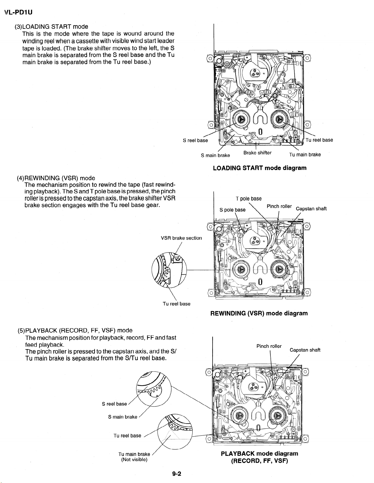
(3)LOADING START mode
This is the mode where the tape is wound around the
winding reel when a cassette with visible wind start leader
tape is loaded. (The brake shifter moves to the left, the S
main brake is separated from the S reel base and the Tu
main brake is separated from the Tu reel base.)
S reel base
\
reel base
(4)REWINDING (VSR) mode
The mechanism position to rewind the tape (fast rewind-
ing playback). The S and T pole base is pressed, the pinch
roller is pressed to the capstan axis, the brake shifter VSR
brake section engages with the Tu reel base gear.
VSR brake section
\
Tu reel base
S main /brake
Brake shifter
LOADING START mode diagram
T pole base
S pole base
\
\
Pinch roller
I /
REWINDING (VSR) mode diagram
Tu main brake
Capstan shaft
(5)PLAYBACK (RECORD, FF, VSF) mode
The mechanism position for playback, record, FF and fast
, feed playback.
The pinch roller is pressed to the capstan axis, and the S/
Tu main brake is separated from the S/Tu reel base.
S main brake
Tu main brake
(Not visible)
/
92
PLAYBACK mode diagram
(RECORD, FF, VSF)
I
Page 29
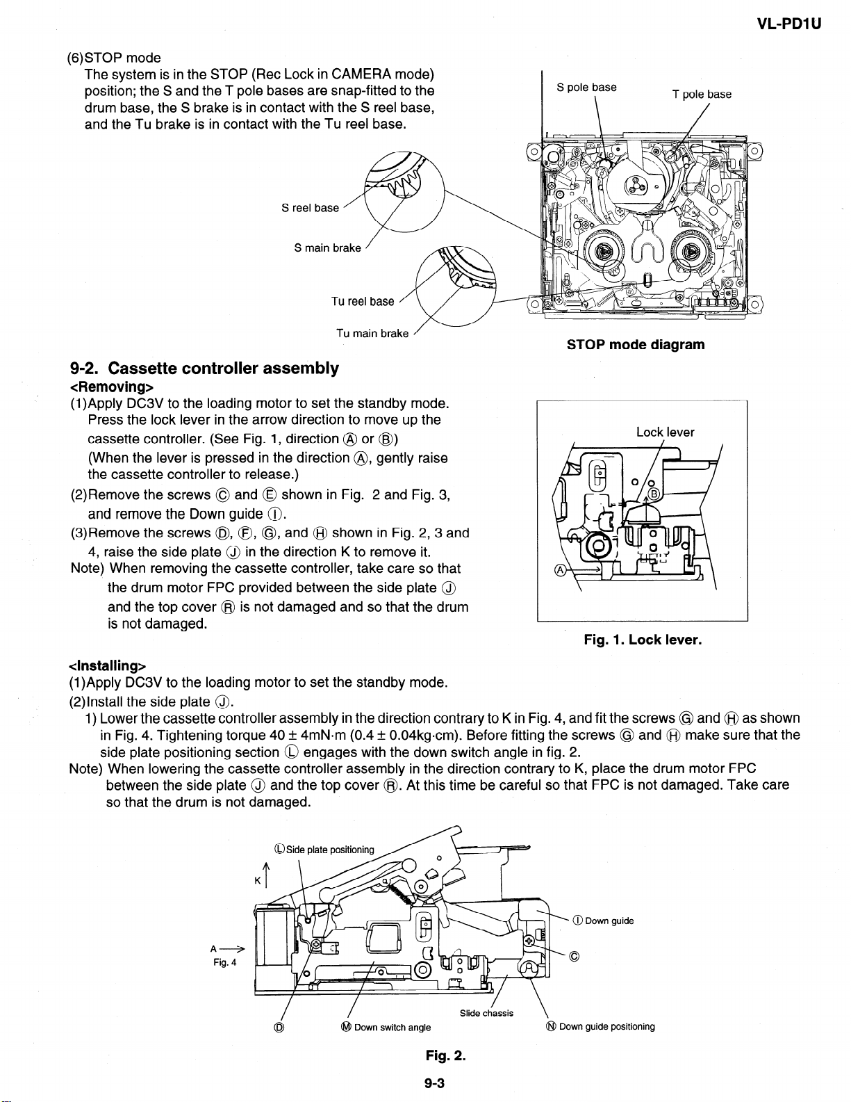
(6)STOP mode
The system is in the STOP (Ret Lock in CAMERA mode)
position; the S and the T pole bases are snap-fitted to the
drum base, the S brake is in contact with the S reel base,
and the Tu brake is in contact with the Tu reel base.
S main brake
S pole base
\
VL-PDI U
T pole base
Tu main brake
STOP mode diagram
9-2. Cassette controller assembly
<Removing>
(1)Apply DC3V to the loading motor to set the standby mode.
Press the lock lever in the arrow direction to move up the
cassette controller. (See Fig. 1, direction @ or @)
(When the lever is pressed in the direction @, gently raise
the cassette controller to release.)
(2)Remove the screws 0 and @ shown in Fig. 2 and Fig. 3,
and remove the Down guide 0.
(3)Remove the screws @, 0, @, and @$ shown in Fig. 2,3 and
4, raise the side plate @ in the direction K to remove it.
Note) When removing the cassette controller, take care so that
the drum motor FPC provided between the side plate @
and the top cover @ is not damaged and so that the drum
is not damaged.
Fig. 1. Lock lever.
<Installing>
(1)Apply DC3V to the loading motor to set the standby mode.
(2)lnstall the side plate 0.
1) Lower the cassette controller assembly in the direction contrary to K in Fig. 4, and fit the screws @ and @ as shown
in Fig. 4. Tightening torque 40 + 4mN.m (0.4 + 0.04kgcm). Before fitting the screws @ and @j make sure that the
side plate positioning section 0 engages with the down switch angle in fig. 2.
Note) When lowering the cassette controller assembly in the direction contrary to K, place the drum motor FPC
between the side plate @ and the top cover @. At this time be careful so that FPC is not damaged. Take care
so that the drum is not damaged.
Lock lever
A+
Fig. 4
0 Side plate positioning
/
0
/
@ Down switch angle
J
.
@ Down guide
Slide chassis
\
@I Down guide positioning
Fig. 2.
9-3
Page 30
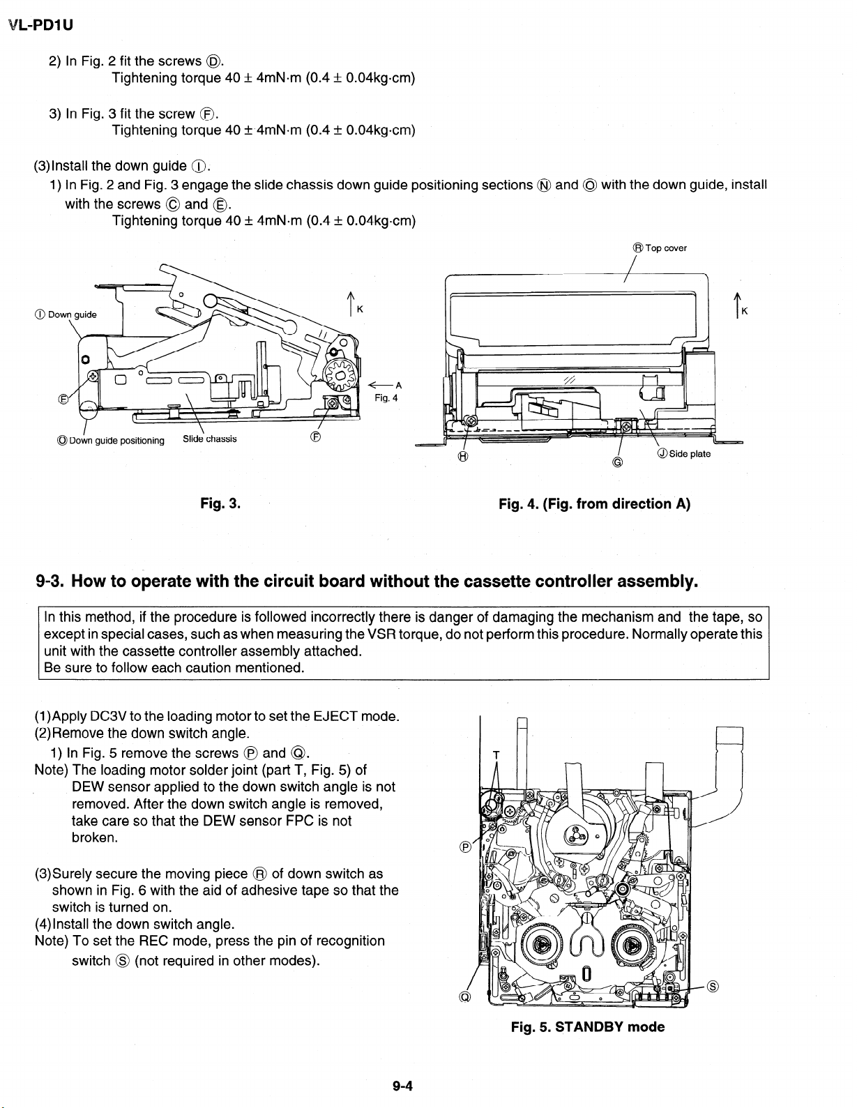
L-PDl U
2) In Fig. 2 fit the screws @
Tightening torque 40 + 4mN.m (0.4 + 0.04kgcm)
3) In Fig. 3 fit the screw @.
Tightening torque 40 f.4mN.m (0.4 + 0.04kgcm)
(3)lnstall the down guide @.
1) In Fig. 2 and Fig. 3 engage the slide chassis down guide positioning sections @ and 0 with the down guide, install
with the screws 0 and 0.
Tightening torque 40 + 4mN-m (0.4 & 0.04kgcm)
@ Top cover
+A
Fig. 4
I
0 Down guide positioning
9-3. How to operate with the circuit board
Slide‘ chassis
Fig. 3.
Fig. 4. (Fig. from direction A)
without the cassette controller assembly.
In this method, if the procedure is followed incorrectly there is danger of damaging the mechanism and the tape, so
except in special cases, such as when measuring the VSR torque, do not perform this procedure. Normally operate this
unit with the cassette controller assembly attached.
Be sure to follow each caution mentioned.
(1)Apply DC3V to the loading motor to set the EJECT mode.
(2)Remove the down switch angle.
1) In Fig. 5 remove the screws @ and @I.
Note) The loading motor solder joint (part T, Fig. 5) of
DEW sensor applied to the down switch angle is not
removed. After the down switch angle is removed,
take care so that the DEW sensor FPC is not
broken.
(3)Surely secure the moving piece @ of down switch as
shown in Fig. 6 with the aid of adhesive tape so that the
switch is turned on.
(4)lnstall the down switch angle.
Note) To set the REC mode, press the pin of recognition
switch @ (not required in other modes).
Fig. 5. STANDBY mode
Page 31

VL-PDl U
(5)Set the test mode (T-01) with the adjustment remote controller without loading the tape. Thereby the mechanism
operation is enabled with the mode key.
(6)To eject, remove the tape (3).
moving
@ Down switch moving
piece
tape
Adhesive tape, ok
Fig. 6.
9-4. Phase matching
For the parts listed below, match the phases as shown in Fig. 7.
(1) AHC cam (2) MODE switch (3) Main cam (4) Sub cam
Note) Before disassembling, check the marker positions carefully.
Note) When installing the engagement gear, make sure that the main cam and sub cam phase matching hole aligns with
the chassis hole.
Note) After phase matching, turn the MODE switch by hand and confirm that it turns almost one complete turn. (After
checking, return it to its original position.)
Phase matching hole \
(for chassis)
Phase matching
mark
MODE switch
Phase matching
mark
AHC cam
Main dam
/
Phase matching hole
(for chassis)
Coupling gear
Fig. 7.
9-S
Sub cam
I
Phase matching hole
(for chassis)
Page 32

L-PDl U
9-5. Reassembly
9-5-l. Reassembly in side of the main chassis.
Note) Numbers before part names are given as a guide to the order of assemblv.
As for greasing/oiling/cleaning places refer to the attached drawings (1 akd 2).
Side surface grease
(2) Pinch drive lever
Shaft grease
(2) Mechanism fixing angle
assembly (Rear surface)
B-4
7
I
Main chassis
A 9 S Tight . Ml .4 x L3
B 9 S Tight . Ml .4 x L2
assembly (Front surface)
Item
Tightening torque Quantity
70mN-m
70mN.m
3
6
se to the cam groove.
Note) The numbers following A and B
indicate the screw tightening order.
Main chassis assembly (Rear surface)
9-6
Page 33

VL-PDl U
Coupling
(4)
(3) Sub
Positioning hole
Cam groove grease
(6) T arm control lever
n _d- -2
/&=tY
(7) AHC control lever
c
\
lrem
I Quantitv I
(2) Loading lever
To cam aroove ‘I
Groove grease \\\y
(1) Shifter drive lever assembly
\w
D Groove grease
/
I
(3) 1 u guide cam
Item
B @ S Tight l Ml .4 x L2
c @ cw01.2-03.0-to.25
D 9 Special screw l
Ml .4 x L1.6
Tightening torque Quantity
70mN.m
40mN=m
2
2
4
9-7
Page 34

VL-PDl U
(4) Intermediate gear angle sub assembly
(1) intermediate pulley assembly
(2) Center pulley assem
Phase match check
B
Enter part of convexity rear surface
Tightening torque Quantity
S Tight l Ml .4 x L2
70mN.m 1
Phase match check
Guide rail sub assembly (Rear surface)
98
I
Page 35

VL-PDl U
S pole base assembly
S loading arm assembly
\
S pressi rre spring
S loading gear
Guide roller assembly
Tu pressure spring
Item ’
F Q CW00.7-02.2-to.25
G g Special screw l
Ml .2 x Ll .8 (Tentative tightening)
Tu pole base assembly
/
, Tu loading arm assembly
Tightening torque Quantity
2
5mN=m
2
(3) Loading motor assembly Grease
\
surface, groove side
surface)
Tu loading gear
A
x
0
K-b, _
(2) Tape guide spring
/
kzI
(2) PB guide spring
ti
I
I
. Grease
(Front surface, rear surface, groove side surface)
Drum base sub assemblv
99
[A 19 S TigGl.4 x L3 1 70mN*m 1 4 1
p Special screw with step-
Ml .4 x L6.25
I
70mN-m
Page 36

L-PDI U
(2) Down
angle
switch attachment ’
.
. .
Item
A
x
SL chassis holder S
k
A 9 S Tight . Ml.4 x L3
Tightening torque Quantity
70mN.m
2
Ia
Fit, clamping the plate
(1) AHC assembly
9-l 0
Page 37

9-5-2. Reassembly in side of the Slide chassis.
Note) Numbers before part names are given as a guide to the order of assembly.
As for greasing/oiling/cleaning places refer to the attached drawings (3 and 4).
VL-PDl U
Fit the main brake SPR from
above, and close with the hook.
(3)
n /\
(3) one pc.
(7) one pc.
(8)
456
0
one pc.
(8)
I
I
*@Tightening torque
40 + 4mN.m
(0.4 +_ 0.04kgocm)
382 @)
(3
,Grea
(2)
382
P
Tightening torque
40 + 4mN=m
(0.4 + 0.04kggcm)
9-l 1
Note) Be careful not to scratch or denttithe
---14
be careful not to deform the tension
band in handling it.
Page 38

VL-PDl U
9-5-3. Main chassis assembly and slide chassis assembly assembling method
(l)Set the US mode (see the figure below).
(2)lnset-t the slide chassis side operation pins (0 tension arm, @ Tu guide arm, @ pinch lever) in the position shown
below at the main chassis.side, move the slide chassis in the arrow direction, using @ to @ as guides, insert the
loading lever operation pin into the groove of slide chassis, and install with the 4 screws.
@Tightening torque
40 & 4mN-m
(0.4 + O.O4kg-cm)
Numbers before part names are given as
a guide to the order of assembly.
When treating the sensor FPC wire, pay
attention to the part A shown in Fig. 6.
Oil application place is shown in Fig. 5.
*@Tightening torque
70 + 7mN.m
(0.7 + O.O7kg-cm)
Page 39

GREASE/OIL APPLICATION
PCS.
Tightening torque
40 f: 4mN.m
(0.4 + 0.04kgocm)
VL-PDl U
0. 1.
Fig. 1. Side of the main chassis
Brake shifter
(G3 : Greasing
@ : Greasing
I I I
I
Fig. 4. Side of the slide chassis
I
G
d”
Tu guide arm
I I. y 0
I
Pinch lever
0 : Oiling
G : Greasing
0
m : Greasing
9-13
G : Greasing
0
m : Greasing
Fig. 3. Side of the slide chassis
0
c2
0
0
Swing arm
Fig. 5. After joining the main chassis
and slide chassis
Page 40

i/L-PDl U
Mode switch
Enabled aft
assembling
T arm control lever
h-
Pinch control lever
Pinch drive lever
From rear surface side
Main cam surface
AHC cam
Sub cam
tar
side
0
0
O 0
&
%
Intermediate gear angle
0 0
Shifter drive lever
after
“cl
Loading lever
Tu guide cam
S loading arm
Tu loading arm
Drum base assembly
Fig. 2. Side of the main chassis
ensor FPC
Fig. 6. Sensor FPC wiring
9-14
Part A
Page 41

VL-PDl U
9-6. Removing the cassette
(1)Apply DC3V to the loading motor unload slightly.
(2)After the tape is slackened, turn
direction, Fig. 1)
(3)Repeat the operations (1) and (2). After the pole base has been completely unloaded, ascertain that the tape is not
loose.
(4)Finally apply again DC3V to the loading motor, so that the cassette controller ejects.
(5)Take out the cassette.
Note) DC3V is applied
to the loading motor as shown below. Then, the mechanism moves
the rotor (lower side of mechanism) of capstan motor to tighten the tape. (Arrow
in the unloading direction.
Plus pole
I
I
Minus pole
Capstan motor rotor rotation direction
(from rear side of mechanism)
Loading motor
/
Fig. 1.
Page 42

L-PDl U
10. ADJUSTING THE ELECTRICAL CIRCUITS
Before starting the electric circuit adjustment
l The adjustment methods described herein are used, in most cases, when the expendable mechanical parts, including
the video head, have been replaced, at which time the electrical circuits need to be readjusted. Before adjusting the
electrical circuits, make sure that the mechanism works properly (i.e., the mechanism is properly adjusted). lncase of
the occurrence of any problem to the electrical circuits, be sure to use the specified measuring instruments to locate
the area to which the problem is occurring, and then take the necessary action,‘including repair, replacement or
adjustment, exactly as instructed in the electrical adjustment methods that will follow.
Do not attempt to make adjustments without using the proper measuring instruments.
l This machine is configured so that the electrical circuits inside its PWB unit are composed, for the most part, of high-
density, small surface-mounted component parts for downsized machine body.
To perform repair service or parts replacement, do so using a soldering iron, but in as short a time as possible; this is
because surface-mounted component parts are generally so small in size and susceptible to heat, as compared with
the large discrete parts used in TV sets, desk-top video decks, etc., that attempting to heat their electrodes for a longer
time than is necessary with a soldering iron may result in their becoming defective.
This applies particularly when replacing the laminated chip capacitors.
For this purpose, ceramic soldering irons with a temperature regulator are recommended (iron tip temperat
and soldering time 5 seconds or shorter).
ure 250°C
The VL-PDI U and other models that follow are newly equipped with the digital interface function. The Digita
IEEE1394 Standard stipulates that each set with the digital interface function be given its specific ID number. The ID
number is written on the E*PROM of the set while it is manufactured. If the E*PROM alone or the PWB having this E*PROM
on it has been replaced for repair purpose, it is necessary to write a new ID number again. (Note that any replacement
part does not have an ID number yet.)
Accordingly, the repair engineer must obtain the new ID number.
Interface
Head amplifier PWB
If the IC302 (E*PROM) or the head amplifier PWB has been replaced, it is necessary to write a new ID number. (Note that
any replacement part does not have an ID number yet.)
Obtain a new ID number from the service department of sales company. Take the following steps to write the ID number
on the E*PROM.
n How to write an ID number on.the E*PROM (Have the adjustment remote control at hand.)
Take this procedure after all the repair complete.
1. Set the power switch to the “VCR” position.
W
l CAMERA
2. Press the “CONTINUE” key first and then the “VCR ADJ” key, both
located on the adjustment remote control.
Make sure an address appears on the LCD monitor. Be careful not
to press the “CONTINUE” and “VCR ADJ” keys at once.
3. Using the “FF” or “REW” key, look for your target address. To
advance the numbers, use the “FF” key. To move them back, use
the “REW” key.
4. Press the “PLAY” key and the address is set up.
1 o-1
Page 43

Using the “FF” or “REW” key, set up the ID number for the target
5.
address. To advance the numbers, use the “FF” key. To move
them back, use the “REW” key.
6
Press the “PLAY” key and the ID number is set up.
7:
Press the “STOP” key and you go backto the above step 2. Now
write the ID numbers for all the addresses (17E, 17F, 180, 181
and 182).
8 .
Set the power switch to the “OFF” position. Now the writina is
complete.
OFF
VCR
VL-PDl lJ
[PLAY] key
f
FFI key
[STOP] key
[REW] key
[VCR ADJ] key
[CONTINUE] key
VL-PDl U Service jig configuration
7
l@
CAMERA,
HEAD t 0
,_ 8 r’ 1
@
I
Mechanism
1 J
VCR Main PWB
ADJ. REMOTE CONTROL
RRMCG 0033 TASA
I
CAMERA POWER
PWB
VL-PDl U Specifications of service jigs
1 No. 1
I1 T H/A ++ VCR Main (pin80)
1 2
I 3 I VCR Main t) CAMERA POWER (pin80)
r -- ~~~~
I 5 1 VCR Main e CAMERA POWER (pin40)
I 6
I I
I
I
I
1 VCR Main t) LCD Panel (pinl0)(3pcs.)
4 [ VCR Main t) CAMERA POWER (pin80)
I VCR Main t) DV PWB (pin60)
7
8
9
10 1 CAMERA HEAD ++ CAMERA POWER (pin15)
11 1 CAMERA HEAD ti CAMERA POWER (pin17)
12 1 For checking VCR wave form (pin14)
Video output
s output
Battery terminal
Control switch
I
NAME
1 o-2
I
1 QCNW-1762TAZZ 1 BZ
1 QCNW-1769TAZZ 1 BF
1 QCNW-1765TAZZ 1 CA
1 QCNW-1765TAZZ 1 CA
1 QCNW-1763TAZZ 1 BU
1 ‘QCNW-1764TAZZ 1 BW
1 QTANZ0126TAZZ 1 BB
1 QSW-Z0280TAZZ 1 AY
1 QCNW-1771TAZZ 1 BG
1 QCNW-1773TAZZ 1 BH
Part code 1 Price Code
QJAKZOO55TAZZ
QCNW-1775TAZZ
AQ
BP
Page 44

L-PDl U
[TEST POINT]
(Wiring board diagram: Main Side A)
(Wiring board diagram: Sub Side A)
TL930(+)
Shutdown voltage
TL934( -)
Shutdown voltage
1 o-3
Page 45

(Wiring board diagram: Main Side B)
TL803(B OUT) ,
DAC full-scale
IC461
TL8805(HSY)
VF VCO
TL800(HSY)
VCO free-run
VL-PDl U
I
TL8814(VG)
Operation of lamp system
safety defection circuit
TL808(BL_PWR)
mD, MOperation of lamp system
safety defection circuit
TL807(BL PWR)
Operation>f lam’p system
safety defection circuit
-m -A-.._ .- _ _.A . .
IL603(IN I MIG L) -
EE level check
Frequency character
check
/
TL604
(Audio-R out)
EE level check
Frequency character Frequency character
check
EXT MIC
TL605
(Audio-L out)
EE level check
check
EXT MIC
TL2402
_-- ._(EXT MIC R)
EXT MIC
TI 5401
’ --
(EXl
- MIC L)
EXT
MIC
VCO free-run
.TL804(C OUT)
vv YIN.
AGC
DAC full-scale
DAC full-scale
TLGOl(INT MIC R)
EE level check
.
.
1 o-4
Page 46

L-PDl U
[Making adjustments]
Adjusting the servo system controller and related parts
1. Setting the system codes
Replacement of IC703 E2PROM requires the following data to be set in this order. I
[Procedure]
Set the unit to the VCR mode and set the data for each address.
Address
1) Model code 01 00
09 FF
2) Destination code
3) Specifications code
4) Menu selection code
5) Software switching code 05 00
6) Calendar switching code 07 98
When replacing the IC7O3 E2PROM, first make the following settings and then start the I
adjustments.
(1) Electromagnetic conversion (2) LCD
Address
Data
02 01
OA FE
03 10
OB EF
04 FF
oc 00
OD FF
OF 67
Address Data
Data
I
I
I
* Some adjustment step
numbers are followed by
I
when to perform the ad-
I
1 justment.
I Examples
1) During E2PROM replace-
I
ment
1 2) During circuit board (Main)
replacement
I
1 3) During LCD replacement
I 4) During mechanism re-
placement
I
-_--------II) During E2PROM(IC703)
I replacement
I
I
I
I 25 26 27 28 80 80 60 80
2B
l Adjustment with automatic machine
[Procedure]
1) Using the 12 command, set the VCR adjustment mode.
2) Using the 20 command, give the E2PROM Write permission.
3) Set the system code with the 22 command for each type.
4) Using the command, set Write inhibition.
5) Using the command, cancel the adjustment mode.
l Manual adjustment
[Procedure]
Set the VCR adjustment mode, and set data of each address.
1) Set the CAM/OFF/VCR selection switch to VCR.
2) Press ‘CONTINUE” ---+ “VCR adjustment” on the remote controller to set the VCR I
adjustment mode.
(At this time an indication “VCR ADJ” appears at the left upper side.)
Enter a setting corresponding to the address.
Setting method
3) Adjust the address by moving up and down the blinking numeral with the FF and REW
key, and fix the address by pressing the PB key.
4) Adjust to the setting by moving up and down the blinking numeral with the FF or REW 1
key, and set data by pressing the PB key.
5) Press the STOP key to set the address set state.
6) Repeat the operations 3), 4) and 5) as much as input addresses. After completion of I
input of all items hold down the STOP key for about 3 seconds to cancel the VCR I
adjustment mode.
7) Set the CAM/OFF/VCR selection switch to OFF.
CA
50 23 I I I
’
I
I
I
I
I
I
I
I
I
I
I
I
I
I
I
I
I
I
I
I
I
I
1 o-5
Page 47

VL-PDl U
2. Shutdown voltage adjustment
(Wiring board diagram: Sub Side A)
TL930(+)
TL934(-)
I
I
11) During E2PROM replacement (IC703)
I
I
jcpgd
I
I
I
L9ia
-I
CP90
I
I
I
L921
-,I
pqjl
I
I
I
I
[Procedure]
Load the blank cassette into the deck.
1)
Set the unit to the camera mode, and start recording. (LCD : ON, V/F OFF)
i
2)
Press the “CONTINUE” and “TEST SEL” keys on the adjustment remote control in this 1
3)
order.
Select T-03 with the “REW” and “FF” keys and press “PLAY” key.
4
*
This shifts the operation mode to the shutdown voltage adjustment mode.
At this time, the display in which T-03 is flashing changes to the normal REC screen. I
Measure the voltages between TL930 (+) and TL934 (-) using the digital multi-meter,
5)
and supply external power until the power voltage is adjusted to +5.90 VAC.
Press the “SET” key. I
6)
+
This executes automatic adjustment.
At this time, with the “BATTERY” indication appearing only for an instant, the I
adjustment is complete.
Press the “CONTINUE” key on the adjustment remote control.
7)
.
3
HSWP adjustment
[Procedure]
1) Play back the alignment tape in the video mode.
2) Press the “CONTINUE” and “HSWP ADJ” keys on the adjustment remote control in this I 2) During E2PROM replace-
order.
+ This executes the HSWP adjustment.
When the adjustment is successful, the blue LCD lights up and the cassette is
automatically ejected. If not properly adjusted, the red LCD lights up.
I
I
i
I
I
k--5.9OV + 30mV
I
I
I
1 1) During mechanism reI placement
ment (IC302 inside the
I
head amplifier circuit
I
board)
I
I
I
I
I
I
I
I
I
I
I
I
I
I
I
I
I
I
I
I
I
1 O-6
Page 48

L-PDl U
ADJUSTING THE ELECTROMAGNETIC CONVERSION
CIRCUIT SYSTEM
Note:
During the adjustment of the electromagnetic conversion circuit system, keep R404 out 1
of operation.
1. PLL VCO adjustment
[Procedure]
1)Playback the alignment tape (or a self-recorded tape).
2)Call the adjustment mode (V-ADJ).
3)Set the address to “2C”, and call the data.
4) Using the FF key, vary the data that has been called until the playback image screen 1
changes to the blue backscreen. Then use the REW keytovarythedata backward until
the data point is found where the screen starts to switch from the blue back to the I
playback image. At this time, take note of the data obtained at this point.
5) As in the above step 4), vary the data that has been called - this time using the REW 1
key - until the playback image screen changes to the blue back screen. Then use the 1
FF key to vary the data backward until the data point is found where the screen starts I
to switch from the blue back to the playback image. At this time, take note of the data I
obtained at the point.
Playback screen
I
I
I
I
I
I
1 1) During Circuit board (Main)
replacement
I
2) During E*PROM replace-
I
ment
1
I
0000
Blue back
Position @ at which note Position @ at which note
is made of the datum is made of the datum
6) Calculate the data taken note of at the points @ and @I to find the center of these data, I
and shift to and determine the central data by using the FF or REW key.
Example:
If the data taken note of at points @ and @ are 5A and 65, respectively:
2
2
Y
2
13
2
m
Thecentral data is set to “5F”.
5A. 5B.
<
0
5 a>
z
5C.
0000
Step 5)
REW key
5E. 5F. 60. 61. 62. 63. 64.
5D.
0000
Blue back
65
0
ij
I
I
I
I
I
I
I
I
I
I
I
I
I
I
I
1 o-7
Page 49

VL-PDl U
2. Phase and equalizer adjustment + (Performed in the VCR mode) I
[Procedure]
1) Load a self-recorded tape into the deck.
2) After playback for 3 minutes, select the test mode OF using the remote control for 1 2) During circuit board (Main)
adjustment to start the automatic adjustment. (The following sequence is automatically
performed.)
The built-in PTW colour bar is recorded.
-1
VS REW
II) During mechanism re-
1 placement
replacement
I
3) During E*PROM replace-
I
ment
+L
PB
L
Phase and equalizer are adjusted automatically.
Blue LCD comes on.
I
Judg*ment
I
+
OK
4
NG
Red LCD comes on.
\1
Tape is EJECT.
Error rate check
3)
Select and fix the TEST MODE OC on the adjustment remote control.
Manual adjustment method (video adjustment mode)
4
*
Perform this adjustment with the self-recording/playback in the LP mode.
For phase, vary the data for the address 2B, and for equalizer, vary the data for the I
address 27, to set the error rate to the minimum.
I
I
I
I
Synchronization error Error rate
I
Synchronization error 20 or less
Error rate
200 or less (SP Mode)
330 or less (LP Mode)
I
I
I
I
I
I
I
I
I
I
I
I
I
I
1018
Page 50

WL-PDI U
ADJUSTING THE VIDEO I/O CIRCUIT SYSTEM
(Wiring board diagram: Main Side B)
-TL1402
AGC
1. I/O Filter adjustment
Mode 1 Colour bar input EEmode
Procedure 1) Call the adjustment mode (V-ADJ).
2) Set the address to “2D”, and call the date.
3) Set the date to “80”.
Examples l During E*PROM replacement.
2. PC0 D/A-Y adjustment
Test point
Mode
Procedure
Examples
TLI 408 (connected to oscilloscope)
EE mode for any given video signal
Call the adjustment mode (V-ADJ).
1)
Set the address to “22”, and call the date.
2)
(100% white signal is output.)
Vary the date with the FF and REW keys to set the signal appearing at TL1408 to 1 .OVp-p + 0.05.
3)
l During E*PROM replacement. l During IC4401 replacement. l During ICI401 replacement.
l During circuit board (Main or Sub) replacement.
I
TL1407
PC0 D/A-C
\
TL1408
PC0 D/A-C
____--_____
1 .o * 0.05
U-I
-____ -.
l During circuit boards (Main and Sub) replacement.
3. PC0 D/A-C adiustment
Test point
Mode
Procedure
Examples
TLI 407
No input
1) Call the adjustment mode (V-ADJ).
2) Set the address to “23”, and call the data.
3) Vary the data with the FF and REW keys to set the signal appearing at TL1407 to 1.28 Vp-p + 0.05.
l During E*PROM replacement l During IC4401 replacement. l During IC1401 replacement.
0 During circuit board (Main or Sub) replacement.
1.28 + 0.05
l During circuit boards (Main and Sub) replacement.
1 o-9
Page 51

4. AGC adiustment
1 Test point 1 TL1402
Mode
Procedure
100% white signal (half colour bar)
1) Call the adjustment mode (V-ADJ).
EE mode
2) Set the address to “24” and call the data.
3) Vary the data with the FF and REW keys to set the signal appearing at TL1402 to 1 .OVp-p rt 0.05.
Examples
l During E2PROM replacement. l During IC4401 replacement. l During ICI401 replacement.
l During circuit board (Main or Sub) replacement.
l Durino circuit boards (Main and Sub) replacement.
.
5. Frame lack adjustment
Procedure
2) Set the address to “21” and call the data.
3) Vary the data with the FF and REW keys to set the “80”.
Examples l During E2PROM replacement.
ADJUSTING THE LCD CIRCUIT
* To make this adjustment, set the backlight switch to the “NORMAL” position.
VL-PDl U
(Wiring board diagram: Main Side B)
TL800(HSY)
VCO free-run
I \
TL803( B OUT)
DAC full-scale
TL806(BL_GND)
Operation of lamp system
safety defection circuit
/
TL808(BL_PWR)
‘Operation of lamp system
safety defection circuit
TL807(BL_PWR)
-Operation of lamp system
safety defection circuit
- TL801 (R OUT)
DAC full-scale
+ TL802(G OUT)
DAC full-scale
VCO free-run
1040
\ TL804(C OUT)
DAC full-scale
Page 52

VL-PDl U
1. VCO free-run adjustment
Test point TL800 (HSY)
Address VCR ADJ 32
Mode
Procedure
VCR AV input
1) Change the VCR ADJ address 53 to FB.
2) Connect the Frequency counter to TL802 and adjust it to the specified rating with the VCR ADJ address
32
3) Set the VCR ADJ address 53 to FF.
Note: Setting the address 53 to FC/FD turns off the LCD screen, but keep changing the data. Ot-herwise
the original screen will not come on again. In such case, the address and the data cannot be
checked on the LCD screen.
Adjustment
15734kHz + 1 OOHz
rating
Examples
l During IC703(E2PROM) replacement.
l During IC801 replacement.
2. DAC full-scale adiustment
Test point
Address
Mode
Procedure
Adjustment
rating
TL801 (R OUT) TL802 (G OUT) TL803 (B OUT) TL804 (C OUT)
VCR ADJ 3D (R) VCR ADJ 3E (G) VCR ADJ 3F (B) VCR ADJ 29 (C)
VCR AV input
1) Change the VCR ADJ addresses 46,57 and 69 to 7F, FE and 7F, respectively.
2) With the VCR ADJ address 3D, set the TL801 output voltage to the adjustment rating, and with the
oscilloscope, set the peak voltage also to the adjustment rating, in such a way that the both TP’s
voltages will be averaged into the rated mean value.
3) With the VCR ADJ address 3E/3F/29, set the TL802/803/804 output voltage to the adjustment rating,
and with the oscilloscope, set the peak voltage also to the adjustment rating. ((Same as in Step 2)
above)
4) Set the changed address data back to normal.
Note: Setting each address data back to normal leaves the LCD screen white. At this time, turning off and
on the main power will restore the screen (the lithium battery should be removed).
1 .OOOVp-p + 1 OmV
Examples
1 .OOOV f 1 OmV
_A__
A ~
l During IC703(E2PROM) replacement.
l During IC801 replacement.
10-11
Page 53

3. COM-Bias adjustment
Test point
Address
Mode
Input signal 40% White (or gray scale) signal
Procedure 1) Input white 40% signal as AV input.
Adjustment Minimum
rating Set the point to make the black portion blackest.
Remark
Examples
LCD panel display area
VCR ADJ 33
VCR AV input
2) Set the illuminometer (TOPCON IM-3) on the LCD panel surface.
(Shut off the external light.)
3) Minimize the ripple of output waveform of illuminometer.
Response time : 0.6 sec.
Make this adjustment after 5minute or longer aging.
l During IC703(E*PROM) replacement.
l During LCD replacement.
l During circuit board (Main) replacement.
4. White Balance adjustment
Test point
Address
Mode VCR AV input
Procedure 1) Feed 40% white signal to the AV input jacks and the standard monitor.
Adjustment
rating
Remark
Examples
LCD panel display area
VCR ADJ 30 (R) VCR ADJ 31 (B)
2) Set the Colour luminance meter (TOPCON BM-5) on the LCD panel surface.
(Shut off the external light.)
3) Adiust the VCR ADJ addresses 30 and 31 until it became the same as that of the standard monitor.
Set of the standard W=VF-HL3-136
Set of the limit
Make this adjustment after 5-minute or longer aging.
l During IC703(E*PROM) replacement.
0 During LCD replacement.
R=VF-HLl -048 G=VF-HLI -050 B=VF-HLI -052
l During circuit board (Main) replacement.
VL-PDl U
5. Operation of lamp system safety detection circuit
Test point
Mode
Procedure
I I
Remark
Examples
LCD panel display area
VCR AV input
1) Set the user bright center.
2) Make sure that the lamp indication appears when the 12 ohm (2W) resistor is put between TL807,
808(BL_PWR) and TL805,806 (BL_GND).
BL CTL = Nomal
-
Make this adjustment after 5-minute or longer aging.
l During IC703(E*PROM) replacement.
l During IC8800 replacement..
10912
Page 54

L-PDl U
ADJUSTMENT OF VIEW FAR CIRCUIT
TL8814(VG)
TL8805(
VF VCO
- TL8826
VF VCO
(Wiring board diagram: Main Side A)
1. VF VCO adjustment
Test point 1 TL8805 (HSY)
Address VCR ADJ 70
Mode VCR AV input
Procedure
Adjustment 15.734kHz (NTSC) + IOOHz
rating
Remark
Examples l During IC703(E2PROM) replacement.
2. VF bright adjustment
Test point TL8814 (VG)
Address VCR ADJ 76
Mode VCR AV input
Procedure 1) The input signal must be 3-step wave.
Adjustment 7.5kHz * 0.1 Vp-p
rating
1) Connect TL8826 to 3V.
2) Connect TL8805 to the frequency counter, and adjust to the adjustment standard value at address 78.
3) Open TL8826.
l During IC8800 replacement.
2) Connect TL8825 (lC8800 pin 53) to GND.
3) Adjust the pedestal interval of waveform of TL8814 to the specified level.
(Wiring board diagram: Main Side B)
CJg.center _ ___-_-.__- _____ -_-_-.-__
_1
GND
Remark
Examples l During IC703(E2PROM) replacement.
l During IC8800 replacement.
7.5 Ik 0.1 vp-p
1043
Page 55

3. VF contrast adiustment
Test point TL8814 (VG)
Address VCR ADJ 75
Mode
Procedure
rating
Remark
Examples
VCR AV input
1) The input signal must be 3-step wave.
2) Connect TL8825 (IC8800 pin 53) to GND.
3) Change the address 71/72 to 00.
4) Adjust the pedestal -100% interval of wave form of TL8814 to the specified level.
0.85 + O.lVp-p Adjustment
l During IC703(E*PROM) replacement.
l During IC8800 replacement.
VL-PDI U
, n,l 0.85If:O.l Vp-p,
GND
4. VF y 1 adjustment
Test point TL8814 (VG)
Address VCR ADJ 72
Mode VCR AV input
Procedure 1) The input signal must be 3-step wave.
2) Connect TL8825 (IC8800 pin 53) to GND.
3) Adjust the pedestal -50% interval of wave form of TL8814 to the specified level.
Adjustment
rating
1.5 + 0.1 vp-p
r\ 1.5kO.l vp-p
J-L ”
Remark
Examples
5. VF sub briaht
Test point 1 View Far panel area
Address VCR ADJ 74 (R) VCR ADJ 73 (B)
Mode VCR AV input
Procedure
Adjustment
rating
Remark Make this adjustment after 5-minute or longer aging.
Examples
l During IC703(E*PROM) replacement.
l Durina
IC8800 replacement.
R/B adiustment
1) Feed 40% white signal to the AV input jacks and the standard monitor.
2) Adjust the tone of the colour with the VCR ADJ addresses 73 and 74 until it becomes the same as that
of the standard monitor.
l During IC703(E2PR.0M) replacement.
l During IC8800 replacement.
I
10-14
Page 56

bfL-PDl U
ADJUSTING THE TOUCH PANEL CIRCUIT
1. Touch panel position detection adjustment
Test point
Mode VCR AV input
Procedure 1) Enter the adjustment of touch panel adjustment mode.
Examples
LCD panel display area
2) Press successively the two-point OSD indication which appears on the LCD indication surface.
Note: To set the touch panel adjustment mode, press “CONTINUE” -+ “TEST” on the remote control for
adjustment, adjust the address to “OE” with FF/REW, and press the PB key.
ADJUSTING THE MIC AMP CIRCUIT
(Wiring board diagram: Main Side B)
TL603(INT MIC L)
EE level check \
Frequency character
check
TL604
(Audio-R out)
EE level check
Frequency character
check
EXT MIC
TL605
(Audio-L out)
EE level check
Frequency character
check
EXT MIC
\
TL2402
(EXT MIC R)
EXT MIC
TL2401
(EXT MIC L)
EXT MIC
+ TL601 (INT MIC R)
EE level check
1. EE level check
Measuring instrument Valve voltmenter
Test point TL605 TL604
Mode
Adjustment rating -1OdBs I!I 3dB
1 Test signal IlkHz -54dBs sine wave
Procedure 1) Input 1 kHz, -54dBs sine wave into TL603(lNT MIC L), TLGOl(INT MIC R).
Remark TL608 : OPEN
Examples
P-ON (CAM)
2) Make sure that the signal level of TL605 Audio-L out and TL604 Audio-R out is within the
standard limits.
IO-15
Page 57

2. Frequency character check
Measuring instrument Valve voltmenter
Test point TL605 TL604
Mode
Adjustment rating
Test signal
Procedure
1 Remark
Examples
P-ON (CAM)
(1 kHz standard) IOOHz : -2dB + 3dB
1 OOHz, 1 OkHz -54dBs sine wave
1) input IOOHz, -54dBs sine wave and then IOkHz, -54dBs sine wave into TL603 (INT MIC L)
and TL601 (INT MIC R).
2) At this time make sure that the signal level of TL605 Audio-L out and TL604 Audio-R out is
within the standard limit (1 kHz standard).
TL608 : OPEN
3. EXT MIC adjustment
1 Measuring instrument 1 Valve voltmenter
Test point TL2401 TL2402
1 Mode 1 P-ON (CAM)
Adjustment rating
Test signal
Procedure
Remark
Examples
I
-8dBs + 3dB
1 kHz -63dBs sine wave
1) input 1 kHz, -63dBs sine wave into TL2401 (EXT MIC L), TL2402(EXT MIC R).
2) Make sure that the signal level of TL605 Audio-L out and TL604 Audio-R out is within the
standard limits.
TL608 : Connect the GND
I
VL-PDl U
IOkHz : -5dB + 3dB
I
DV INTERFACE ID SETTING
1. DV interface ID setting
Address
Mode
Adjustment rating
Procedure
17E, 17F, 180, 181, 182
VCR
*1*2, *3*4, 0*5, 00, 01
1) Using the 12 command, set the VCR adjustment mode.
2) Using the 20 command, give the E*PROM Write permission.
3) Set the ID numbers as follows.
High-order 20 bit
OlOOOh 41 OOOh-4FFFFh For
OlOOOh 50000h-5FFFFh For Line 2 (for 65,535 sets)
01 OOOh 60000h-6FFFFh For
OlOOOh
The high-order 20 bit is set with OlOOOh fixed. For low-order 20 bit, individual ID number is set
for each set within the limits specified above for each production line.
4) Using the command, set Write inhibition.
5) Using the command, cancel the adjustment mode.
Note: Low-order 20 bit
*5*4*3*2*1 h
Low-order 20 bit
OOOOOh-OOFFFh
Line 1 (for 61,440 sets)
Line 3 (for 65,535 sets)
Service and repair parts (for 4,095 sets)
lo-16
Page 58

L-PDl U
1 O-2. Camera Section Adjustments
1 O-2-1. Camera section service
(1)Camera adjustment is performed after the set has been completed.
(2)Subjects, measuring instruments and jigs needed for camera section service and adjustments
l Gray scale chart
l White chart
l Colour bar chart
l Oscilloscope
l Digital voltmeter
l Vector scope
l Frequency counter
l Illumination meter
l Colour temperature meter
l Colour temperature conversion filter HOYA “LB-1 65”
l Colour video monitor
l Video output cable
l Halogen lamp: 2 PCS. l AC adapter
l Extension cables
l Remote control unit for servicing
10-2-2. List of camera jigs and tools
Colour temperature
PC plate connector drawer
7 Remote control until for servicing
conversion filter JiGHOYA-LB165
JiGTH-SSI 0
RRMCG0033TASA BT
Note: N indicates a new jig.
b-
L- by
_- b-
--
Q
10-2-3. Adjusting the camera unit
(l)Preparations for adjustments and items to be checked
1) Set up the light box so that the entire pattern is evenly lit. Set the colour temperature to 3200OK.
2) Use test patterns that are not dirty nor discoloured.
3) If the electrical circuitry gets in trouble, be sure to pinpoint the trouble spot with a measuring instrument and repair
or replace the defective part.
(2)Remote control for servicing RRMCG0033TASA
To adjust the camera section of this machine, the remote control for servicing (RRMCG0033TASA) is used. The
adjustment is made in such a manner that the remote control writes necessary data by way of the microprocessor to
the specific addresses on the E2PROM (IC502 and the ROM on the lens unit).
1) To adjust the camera:
Press the “CONTINUE” key first and then the “CAM ADJ” key.
This will show
CAM ADJ
. . . . . ., . . . . . ., . . . . . ., . . . .,
. ::::::
i: :: :::
:
on the LCD screen, thereby having the camera unit ready for the adjustments.
. . . . . . . : . . . . . i . . . . . i . . . . . i
10-17
Page 59

2) Descriptions of the displays
VL-PDl U
CAM
. . . . . . . . . . . . ., . . . . . . .
: :: :: :::
: :: :: :::
::::i .
. . . . . . . . . . . . .
.....-.
. . . . i . . . . . . i : ,....i
ADJ (Indicates the camera adjustment mode.)
. . . . . . . . . . . . . . . . . . .,
: :: :: :::
::.:: .
: :: :::
.-.....
(Address value) (Data value)
*The address values for this machine range from 0000 to 05FF.
*The data include byte data (the last two digits are effective) and 2-byte data (the last three digits are effective).
3) Descriptions of the remote control keys
“FF” key:
Increases the address and data values.
“REW” key: Decreases the address and data values.
“PLAY” key: Specifies addresses and calls the data.
This key also fixes (i.e., writes to the E2PROM) the data values.
“STOP” key:Clears the data to enable the selection of address.
4) Operation flow
> FFor REW -----+ PLAY - FFor REW ------+ PLAY ---+ STOP
Address is selected and specified, with the data called. Then the called data are selected and
fixed. The operation flows in this sequence.
5) When the adjustment is complete:
Press the “CONTINUE” key to let the “CAM ADJ” display disappear from the screen.
Note: Before terminating the adjustments, make sure that the adjustment mode is neither the auto-focus function
adjustment mode nor the camera signal system adjustment mode (these modes are mentioned later).
Camera unit adjustment modes
The camera unit is adjusted in two types of modes: the auto-focus function adjustment mode and the camera signal
system adjustment mode.
_ ’
Note: Each E2PROM contains the adjustment item data as shown below. If it is changed, data rewriting and confirmation
of latest data must be performed.
1) E2PROM on lens unit of camera head section
Lens data, LCD drive timing data
2) IC703 on main unit
Signal system adjustment data
(3)Auto-focus function adjustment mode
l The camera unit uses a microprocessor-controlled auto-focus zoom lens.
The auto-focus circuit incorporated in this unit is designed to execute the image processing where the focusing action
is done by taking advantage of the fact that the high-frequency components in the image signals increase as the focus
intensifies. Moreover, to achieve high magnifying power with a small lens, the camera unit incorporates the inner focus
system in which the focus is shifted by moving the master lens (rear lens) back and forth. This inner focus system is
a full-range focus type by which the focus can be shifted from approximately 10 mm to the infinity. It should be noted,
however, that since the closest subject distance at the telephoto end is fixed at 1.5 m, subjects in a closer range than
1.5 m at the telephoto end will be out of focus. For this reason, the unit is designed so the zoom control is automatically
shifted to the wide angle side until the position is found where the subject can be focused on.
In the auto-focusing system of this until, the following constitute the important factors:
l Master lens position detection data
l Iris position detection data
.Zoom lens position detection data
These detection data are handled and stored by the microprocessor, lens by lens, into the E2PROM.
Therefore, in the following cases, the auto-focus function adjustment is required:
*When the lens has been replaced
@When the CCD has been replaced
*When the E2PROM (located on the lens unit or IC502) has been replaced
1) Shifting to the auto-focus function adjustment mode
Set the data for the address “05FE” to ” [.y:i[.y,< 01 ‘I.
9
This makes the screen fade temporarily in white and shifts to the auto-focus function adjustment mode.
*When this adjustment mode has been shifted to, make the adjustment according to (5) Camera unit adjustment
procedure.
* In this adjustment mode, the lens can not be operated.
lo-18
Page 60

dL-PDI U
2) Shifting to the normal operation mode
Set the data for the address “05FE” to ” ~.1_j~.‘.~_j FF”.
This makes the screen fade temporarily in white and shifts to the normal operation mode.
Press the “CONTINUE” key, and the “CAM ADJ” display goes out of the screen, enabling the normal operation.
(4)Camera signal system adjustment mode
In the camera signal system adjustment mode, the automatic white balance is disabled to allow for the adjustment of
the camera unit. At this time, the white balance mode is fixed at the INDOORS mode and the focus mode is switched
to the manual focus mode.
Shifting to the camera signal system adjustment mode
1)
Set the data for the address “OOBO” to ” i._../ i..../ 00”.
This shifts the mode to the auto-focus function adjustment mode.
*When this adjustment mode has been shifted to, make the adjustment according to (5) Camera unit adjustment
procedure.
Shifting to the normal operation mode
2)
Set the data for the address "OOBO" to ” ~_~.~$~~_~~ FF".
This shifts the mode to the normal operation mode.
Press the “CONTINUE” key, and the “CAM ADJ” display goes out of the screen, enabling the normal operation.
(5)Camera unit adjustment procedure
9
a
.a..... .......
a
0
e
1. Auto focus adjustment
2. Iris basic adjustment
3. Black balance adjustment/A/F noise adjustment
4. Iris AE adjustment
5. White balance coarse adjustment
I
1
6. Colour gain coarse adjustment
7. White balance adjustment.
8. Colour gain adjustment
9. Auto white balance adjustment
w
I
* The above 1. Auto-focus function adjustment and 2. iris basic adjustment are performed in the auto-focus function
adjustment mode, whereas the other adjustments are made in the camera signal system adjustment mode.
* After completing the auto-focus adjustment mode, set the camera signal system adjustment mode. (Take care that the
adjustment mode transfer address is different.)
(6)Gyro unit replacement method
I) Replacing the lens without replacing the gyro sensor unit
The gyro adjustment data has been written in the E2PROM of lens. Write the data of address 456 to 459.
2) Replacing the gyro sensor
After replacing the specified gyro sensor, write the following
Address Data
456 01
457 EO
458 03
1 459 1 80 1 Replacing Sl (RSNSG0005CEOl) 1
Replacing S2 (RSNSG0004CEOl)
Replacing S2 (RSNSG0004CEOl)
Replacing Sl (RSNSG0005CEOl)
IO-19
data in the address 456 to-459.
Page 61

1 O-2-4. Adjustment procedures
Item
(1) Auto-focus adjustment
Adjustment method
Set the unit to the auto-focus function adjustment mode and write data to the
address “05FD” one after another. This executed the adjustments automatically.
The items to be adjusted are as listed below. Every time an adjustment is made
properly, the data “FF” is written to the address. After each adjustment, make
sure that the adjustment has been made properly, and then go on to the next
adjustment item.
Address Data Adjustment item
05FD . OOOC MR censor adjustment
0012 WIDE end adjustment
0008 TELE end focus 00 position adjustment
0006
WIDE end focus = position adjustment
Note 1: To adjustment of 00 position is executed by actually picking up the image
of subject. For this adjustment use the subject with clear profile.
Especially, if the adjustment of TELE end focus 00 position is made
without picking up the image of remote subject, adjustment failure may
occur.
Adjustment of WIDE end focus 00 position: 3 m or more
Adjustment of TELE end focus 00 position: 50 m or more
Note 2: In case of = position adjustment the field depth is important to ensure the
adjustment accuracy. If the field depth is high, the focus becomes too
stable , which may cause incorrect adjustment of 00 position. Therefore
the adjustment must be made with low field depth (with iris opened).
The iris can be opened with the high-speed shutter.
1. It returns to the normal operation mode.
2. In the normal operation mode, set the high-speed shutter mode until the iris is
opened. (Refer to the operation manual.)
3. Display “CAM ADJ” with the remote control for service.
4. It shifts to the auto-focus adjustment mode.
5. Perform the 00 position adjustment.
6. After completing the 00 position adjustment, return the high-speed shutter
mode to the normal mode.
(2) Iris basic adjustment
This is for adjusting the operating point of the hole element installed in the iris
meter of the lens.
Set the unit to the auto-focus function adjustment mode and write data to the
address “05FD” one after another. This excutes the adjustments automatically.
The items to be adjusted are as listed below. Every time an adjustment is made
properly, the data “OOFF” is written to the address.
Address Data Adjustment item
05FD
* After completion of 1. Auto-focus adjustment, 2. Iris basic adjustment once
restore the regular operation mode. Data “05OF” is written in the address
“01 EB”.
(3)Blackbalanceadjustment/A/Fnoise 1) Prior to the adjustment, initialize the data for the addresses “007A”
adjustment
“007C”, “007E”, “0080”, “0082”, “0084”.
Write ” i:E i:E FF” (the last two digits are effective) to all of these address.
2) In the camera signal system adjustment mode (the data “~‘-‘.‘~?‘*‘~OO” is written to
the address “OOBO”), write the data “i*““i i? 01” to the address "OOBl ” This starts
the adjustment automatically. When the adjustment is completed properly, the
data “OOFF” is written automatically.
0009 Hall offset adjustment
OOOA Iris offset adjustment
OOOB
Iris close adjustment
. . . . . . . . . . . .
L . . . . . ‘. . . . . .
1 O-20
Page 62

V’L-PDl U
Address: “OOB2” AE CVT
Measuring instrument:
Object:
Data variation width:
S terminal luminance signal output (75 Q termination)
Oscilloscope (horizontal sync)
G rey scale
“0000” to “OOFE”
level
(not includin
5) White balance coarse adjustment
Measurement terminal:
EE output
(1)lndication on the vector scope is observed in the grey scale standard record
state, data of address “0018” and “001 A” are rewritten, and an adjustment is
made so that the luminous dot is located in the position of burst ratio:
Address: R-Y 0 + 5%
“0018” CGAIN KR W
B-Y 0 + 5%
“001 A” CGAIN-KB-W
Measuring instrument:
Vector scope
Object:
G rey scale
Data variation width:
“0000” to “03FF”
6)Colour gain coarse adjustment
Measurement terminal:
EE output
Address:
“012B” CGIN RYG
“012D” CGIN BYG
“0128” CMAT RYG
(l)The colour bar chart is imaged, and the picture angle is adjusted so as to get
white level 650 mV. Indication on the vector scope is observed, the data of
address “012B”, “012D”, “0126” and “0128” are rewritten, and setting is made
so that the red and blue luminous dots are located in the following positions.
The gain of vector scope must be set on 75% amplitude point on the B-Y axis.)
(The red phase is adjusted at the address “0218”, and the blue phase is
adjusted at the address “0126”.)
“0126” CMAT BYG
Measuring instrument:
Vector scope
Object:
Colour bar chart
Data variation width:
“0000” to “OOFF”
Red amplitude
Blue amplitude
Red phase
Blue phase
1.60 + 0.1 time (burst ratio)
1 .I5 + 0.1 time (burst ratio)
103O k 2”
344” t 2”
1 o-21
Adjustment address
: “012B”
: “012D”
n “0128” .
- “0126” .
Page 63

EE output
Address:
“0018” INDOOR W/BR
“001 A” INDOOR W/BR
Measuring instrument:
Vector scope
Object:
G rey scale
Data variation width:
“0000” to “03FF”
Address:
“012B” CGIN RYG
“012D” CGIN BYG
“0128” CMAT RYG
“0126” CMAT BYG
Measuring instrument:
Vector scope
Object:
Waveform monitor colour bar
chart
Data variation width:
“0000” to “OOFF”
(1) Colour gain adjustment is performed repeatedly.
Adjustment address
Red amplitude
Blue amplitude
1.60 k 0.05 time (burst ratio)
1 .I 5 + 0.05 time (burst ratio)
103O + I”
344” + 2”
VL-PDl U
: “012B”
: “012D”
n “0128” .
= “0126” .
(9)Auto white balance adjustment
l Measurement terminal:
EE output
l Address:
“006A” OUTDOOR R
“006C” OUTDOOR B
l Measuring instrument:
(l)The colour temperature conversion filter (LB1 65) is mounted in front of lens.
(2) Indication of vector scope is observed in the grey scale standard record state,
and an adjustment is made so that the luminous dots are located in the
following positions:
R-Y 0 + 5% (burst ratio)
B-Y 0 + 5% (burst ratio)
Vector scope
l Object:
G rey scale
l Data variation width:
“0000” to “03FF”
After completion of adjustment set the regular operation mode (the data ” ..’ _: .I,,: FF” is written in the address “OOBO”.)
1 o-22
Page 64

VL-PDl U
11 m USEFULTIPS (PROBLEMS DIFFER FROM THOSE FOUND ON VHS OR 8MM
DECKS BECAUSE THE SIGNALS ARE DIGITALLY PROCESSED.)
>amera (EE mode)
JCR (EE mode)
\
Blueback fails
to appear.
J c
Problems
Major circuits to be checked
l CCD
l Camera circuits (CDS, ADC, DSP)
. PPW (IC4401)
l LCD_DSP (ICSOO)
l System controller (IC701)
. VI0 (IC1401)
l Mechanical controller (IC7701)
l LCD_DSP (ICSOO)
/
l System controller (IC701)
0 Zoom (IC251)
l CLOCK GENERATOR (IC471)
Camera (REC mode)
VCR (PB mode)
\
Picture fails to
appear when tape
recorded on this
unit or another unit
is played back.
(EE OK)
Camera (REC mode)
VCR (PB mode)
2
Blueback when
tape recorded on
this unit or another
unit is played back.
(EE OK)
/ .
l Zoom (IC251)
l CLOCK GENERATOR (IC471)
0
\
. PLL (lC3401)
l ATF (lC3402)
l Head amplifier (IC301)
*
/
Dirty or defective video head
\
11-l
Page 65

VL-PDI U
There is considerable
randam block noise.
Page 66

1
IC802 24pin R Output(1 H)
IC802 6pin R Input (1H)
VF
@
@
LCD Panel
“W
0 G m @
@
@ B >@ @
?
@
LCD DSP LCD INTERFACE
PPW
j q
El401 81 pin Y Output
IC4401 112pin ZYP3 Input
IC4401 27pin LDC3 Output
IC4401 88pin C Output
IC4.401 121pin ZCP3 Input
CAMERA DSP
WAVEFORM DIAGRAM (DURING COLOUR BAR RECORDING)
Page 67

.
IC441 175pin RecGATE Output
4
‘*
I I ’ 5ne’d
i-r--
1 =p*lO
I ’ ’ 5g’d
I I I
IC441 174pin RecDATA Output
363301
BTOB
IC441
TRANSPORT
CODEC
PPW
REC GATE
*
IC441 8pin VDATA3 Input
“” v
1
0 =l*ln
ti
ZYP
/
ZCP
/
WAVEFORM DIAGRAM (DURING COLOUR BAR RECORDING)
Page 68

s - 2
ZQOM - ; t _
CODEC
=I
lC3404 Spin Input
.
tinkId
! '
i I
TRANSPORT
1
EQ/ATF
CLK
lC3402
>@) @-
PE DATA
lC3404 3pin Input
IC3401 54pin Input
DIAGRAM (DURING COLOUR BAR PLAYBACK)
WAVEFORM
lC3402 4pin PBDATA Input
We/d
v
IC441 8pin VDATA3 Output
D ‘P:lo
,
% 1
I
Page 69

REC system
same as in
TRANSPORT
PCM
IC1650
REC DATA
VDATA
IC441QD Input
AIDAT
a2
AUDIO l/O
I$607 AUD-L ADIN~~O’
M,C L
>o
AUD-R ADIN
@
MIC
ICI 601 @Output
WAVEFORM DIAGRAM (1.6 kHz SINE WAVE)
Page 70

0
m
AUDIO OUT R
@,,,I0 OUT L
AUDIO I/O
PCM
1 IC601 1
D-L DA OUT
IC1650
- -
@
I @I-+
I
1 AUD-R-DA-OUT j@
DODAT -
@
I
IC441
TRANSPORT
From lC3404
PB system
same as in Video
WAVEFORM DIAGRAM (1.6 kHz SINE WAVE)
I
IC441 mADATA Output ICI601 ODODAT Input
Page 71

B
313
DV
=
MECHA
a
) OUT
PLL
IC3401
IC402
Shuffling
Memory
b lC7451
I
I
1111
4
PPW
IC4401
I
I
I
I I I
IC201 b IC251
T/G 4 b
ICI2
LENZ
lC552
CAMERA DSP ZOOM
DRIVER
c
1 I
IC702
+ CAMERA
IC501
+ LENZ 4
MICON
MICON
163702 4
CHARAGen
___________ (‘ONTROL___1__-,
I D I I IP@ I I b -REC (EE)+
Page 72

m
31[1
D
v)
m
I
I
;
I I I
I
I I I
I
I I I
I
.YY.~,Y .______________.__--
::..
. . . . . .
y:::::..
.:.:.:.:.:.:.:.,
:.:.:.:.:.:.:.:.:.,
pi
,
,
ICI 51
IObit A/D Conv
VHIADS933Y
LAGC OUT
BLOCK DIAGRAM i
/ PPW SECTION
j
1 PPW
; LCD DSP
I
II
I
ZHDP
ZVDP
=LKp.-g CODEC
ZUVSELP
PADDAO--74
;-
+VDX, HDX
FCK, RBID DZy()-7
I
ADCLK ADINO-9
I
I
8 , I
I I I
I
I
““1 _R:iij:
ZYPb -7
1
I
ZCP_o--7
1111111111 1
MRYIO-17
,
CDHDP. CDVDP
CDUVSELP, CCLKI 35
IC251
ZOOM DSP
RHIXh0553TA
+I
WRTRI
fl MRCIO-13
m I m
- -CDYO “7, CDCO ~7 -
k
180P
WE1
m I m
m I m
I
--ii2
WXAD2 m
m
RXAD2 m
I
m
m
i 3:AGCOUT j
[ 2:VRT
/ 4:VRB
; 10:MCK i
i 6:HDX
1 7:HDX
I
MCKA
I
t
48P
ICI2
PBLK
CLPX, BCPX
FSX, FCX, RSX
RS
I
HI, H2
I I
L-, 1 24p /*VRT, “FIB4 sc1-scj51 L”RT, “,,i 48p /
OFD
Vl, v2, v3, v4
VHILR38573
ICI3
V-DRIVER
‘, ;
OFD
VIX, v2x
VHIX, VH3X
- v3x, v4x
VHlUPD16510
Page 73

IC401
CODEC
RHIX0530TA
176P
IC804
R OUT
,,,,GOUT-..I
VHiMM1323XJ
LCD IhlTERFACE
B OUT
C OUT
24P
FRPV -
CLD, SPD, CTR
EXI, EX2, EX3
-
I
SPS, RES, CLS, LOW
I
LCD UNIT
11111111
PPW
IC4401
RH-IX0522TAZZ
A-Y 0,UT
OSD VD
A-C OUT
OSD HD
163702
CHARA GENE
I
REC CHARA
a
I
IC800
LCD DSP
RH-IX0422TAZZ
RHIX0588TA
REC CHARA BLK
VIDEO I/O
48P
VHICl 11306F
IC802
I
1M SRAM
,
RHIX0560TA
LCD UNIT
I I I
* - - - - --- - - - - - - - - - - CDUVSELP, CDHDP, CDVDP
I
I
ZUVSELP
VIDEO IN/OUT
P2401
i+ SEP Y OUT I I
SEP C OUT
I
I
Page 74

L-PDl U
13-4. CODEC SECTION BLOCK DIAGRAM
13-4
Page 75

.,
i-
;
SYSTEM
CONNECT
:
__.;
i
: .,
: /
j IntMlC
AUDIO L l/O
_ . AUDIO R l/O
I
24P
DFSP +
IC1601
DFSl
16bit DA. AD
VHIPCM3006T
PDAD,
ADMCK
CMODE-
I
---J ,---
PDDA
I
60P
SC7404
SYSTEM
CONNECT
t CS, RD, WR
+ AIDAT
R DA OUT I
L !A OUT
I
. - - SPOUT. - q SPEAKER ;
7
L---l
4
VHIBH7761KV
AUD L AD IN
AUD R AD IN
I-
I
;
1
J7401
DVCONNECT
. . . . . . . . ..__________........................
i
; .,
lC7451
IEEE1 394
VHIXMB66611
100P
x7451
0.192MHz
RCRSC012TTAZZ -
CODEC
BLOCK
TRANSPORT
*--ADATAO 7-m
PCM
IC1650
RHIX0469TAZZ
GSDEB, AIDE b
100P
DFIP
FRPSA --L-
RClLZ0263TAZZ
RCRSCOlO7TAz
w
REC (EE)m-b
I I I I I I I I sP6m I I I I - I I
- - - - n REC (EE), PB- - - - +
Page 76

To VCR
PPW Block
PTW Block
>
Syscon Block
>
Syscon Block
>
I
IC251
PB Y/C Digital Data
I ”
Serial Data
Control/Data Bus
REC & PB Y/C Digital Data
Camera PWB Unit
IC501
Lens
p-cot4
=Jr
Camera Head PWB Unit
Lens Unit
Page 77

EAD AMP P.W.B.
Component Side SIDE A
VL-PDl U
f
cn
Wiring Side SIDE A
1
P307
mmn Elm
Wiring Side SIDE B
16-21
Page 78

F/L-PDl U
CCD P.W.B.
Component Side SIDE A
/
1
Wiring Side SIDE A
Component Side SIDE B
\
4
Wiring Side
SIDE B
16-22
Page 79

Page 80

Page 81

Page 82

Page 83

Page 84

Page 85

Page 86

Page 87

Page 88

Page 89

Page 90

Page 91

Page 92

Page 93

Page 94

Page 95

Page 96

Page 97

Page 98

Page 99

Page 100

 Loading...