

Sharp VL-NZ10S,VL-NZ10H,VL-NZ10E Service Manual
SERVICE MANUAL
12/9/2016
Published in Heiloo, Holland
VL-NZ10S/H/E
SERVICE MANUAL
S01B8VL-NZ10S
LIQUID CRYSTAL DIGITAL CAMCORDER PAL
VL-NZ10S
VL-NZ10H
LIQUID CRYSTAL DIGITAL CAMCORDER
1. SPECIFICATIONS.............................................................................................................................. 2
2. PART NAMES .................................................................................................................................... 3
3. DISASSEMBLY OF THE SET ............................................................................................................ 4
4. MECHANISM ADJUSTMENT JIGS AND PARTS.............................................................................. 6
5. INSPECTION AND MAINTENANCE
ITEMS AND INTERVALS ................................................................................................................... 7
6. MECHANICAL ADJUSTMENTS AND CHECKS................................................................................ 8
PAL
MODELS VL-NZ10S/H/E
7. TAPE RUNNING ADJUSTMENT ..................................................................................................... 11
8. MECHANICAL SECTION ASSEMBLY AND PARTS REPLACEMENT
(DISASSEMBLY AND REASSENBLY) ........................................................................................... 13
9. ADJUSTING THE ELECTRICAL CIRCUITS.................................................................................... 20
10.USEFUL TIPS................................................................................................................................... 38
11.SIGNAL FLOW DIAGRAMS ............................................................................................................. 39
12.BLOCK DIAGRAMS ......................................................................................................................... 42
13.SCHEMATIC DIAGRAMS ................................................................................................................ 48
14.SEMICONDUCTOR LEAD IDENTIFICATION ............................................................................... 102
15.PRINTED WIRING BOARD ASSEMBLIES.................................................................................... 104
16.REPLACEMENT PARTS LIST ....................................................................................................... 121
17.PACKING OF THE SET ................................................................................................................. 142
MODELS
In the interests of user-safety (Required by safety regulations in some countries) the set should be restored to its
original condition and only parts identical to those specified
be used.
CONTENTS
VL-NZ10E
Page
SHARP CORPORATION
1

VL-NZ10S/H/E
12/9/2016
Published in Heiloo, Holland
1. SPECIFICATIONS
Recording/Playback Time: 90 minutes (DVM60, LP mode)
Lens Filter Diameter: 27 mm
Color Temperature Compensation: Auto white balance with white balance lock, outdoor or indoor
Minimum Illumination: 1 lux* (with gain-up, F1.8)
Still Image Compression System: JPEG base line conformance
Still Image Recording Format: JPEG (Exif2.1)
Still Image Recording Medium: SD Memory Card, MultiMediaCard
Power Requirement: DC 7.4 V
Power Consumption: 4.5 W (during camera recording in Full Auto mode with zoom motor off and
Operating Temperature: 0°C to +40°C
Storage Temperature: –20°C to +60°C
Dimensions (approx.): 136.1 mm (W) × 86.3 mm (H) × 58.6 mm (D)
Signal System: PAL standard
Recording System: 2 rotary heads, helical scanning system
Cassette: Digital VCR Mini DV video cassette
Tape Speed: SP mode: 18.831 mm/second
LP mode: 12.568 mm/second
Pickup Device:1/4" (6.4 mm, effective size: 4.5 mm) CCD image sensor
(with approx. 800,000 pixels including optical black)
Lens: 10 × optical/300 × digital power zoom lens (F1.8, f=3.6-36.0 mm), full-range auto
focus
Monitor: 3" (7.5 cm) full-color LCD screen (TFT active matrix)
Microphone: Electret stereo microphone
backlight in normal mode)
Operating Humidity: 30% to 80%
Weight (approx.): 455 g
(without battery pack, lithium battery, video cassette, lens cap, lens hood, hand
strap, shoulder strap and card)
AC Adapter/Battery Charger
(UADP-0334TAZZ)
Power Requirement: AC 110-240 V, 50/60 Hz
DC Output: 7.8 V
Power Consumption: 23 W
Dimensions (approx.): 70mm (W) × 43.5mm (H) × 113 mm (D)
Weight (approx.): 170 g
MultiMedia Card (Supplied Accessory)
Memory Capacity: 8 MB
Power Requirement: 3 V
Operating Temperature: 0°C to +40°C
Storage Temperature: –20°C to +65°C
Specifications are subject to change without notice.
*Minimum illumination: Since there is no widely accepted testing procedure for determining minimum illumination
capability, lux ratings are comparable only between models from the same manufacturer.
2

2. PART NAMES
Front view
Accessory shoe
Stereo microphone
Zoom lens
Cassette compartment door release
Lithium battery
compartment door
Cassette
compartment door
Cassette holder
Rear view
Operation button
CARD selection
switch)
Media Selection
switch (TAPE/
PC connection
jack
DV terminal
AV + S terminal
Jack cover
EarPHONES jack
Rear view
Bottom view
GAMMA/
BRIGHTER button
FADE button
SET button
Remote sensor
button
RECord START/STOP
LCD monitor
Power Zoom Wide
angle/Telephoto
control/
VOLume control
STILL button
Power switch
(CAMERA/VCR
select switch)
Speaker
Card slot cover
DIS button/
MULTI button
MENU button
Tripod adapter socket
Power source mounting surface
Strap loop
Power source release
12/9/2016
Published in Heiloo, Holland
For details on the use of each control.
VL-NZ10S/H/E
3
VL-NZ10S/H/E
FPC
Radiation Angle
LCD Panel
(c)
(c)
(c)
(h)
(h)
(i)
Battery Cover
Lid Lock Fitting
Tilte FPC
Connector
Main PWB
(i)
(i)
(c)
(i)
(i)
(i)
(i)
12/9/2016
Published in Heiloo, Holland
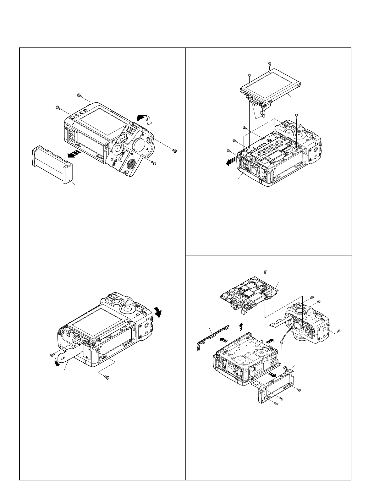
3. DISASSEMBLY OF THE SET
Note:
Before removing the cabinet, turn off the power supply, and ascertain that the battery have been removed.
1.
(c)
(c)
Battery Unit
1) Remove the battery unit.
2) Remove the 4 screws ((c)XiPSN17P03000).
3.
(c)
(c)
1) Remove the 1 screw ((i)XiPSF17P03000) and 2 screws
((h)XiPSF17P02000).
2) Remove the 2 screws ((c)XiPSN17P03000) to detach the
VCR operation PWB. Then remove the FPC of the LCD panel
and FPC of the reflector to detach the LCD panel.
3) Remove the 3 screws ((c)XiPSN17P03000) to detach the
radiation angle.
2.
(i)
1) Remove the 1 screw ((i)XiPSF17P03000) and 1 screw ((q)LXHZ0050TAFF) to detach the AV terminal cover.
AV terminal cover
(q)
4.
1) Remove the 1 screw ((c)XiPSN17P03000) and disconnect
the tilt FPC to detach the main PWB.
2) Remove the lid lock fitting.
3) Remove the 4 screws ((i)XiPSF17P03000) to detach the
battery cover.
4) Remove the 2 screws ((i)XiPSF17P03000) and disconnect
the connector to detach the lens section.
4

VL-NZ10S/H/E
Camera Rear Cabinet
Camera Side Cover
Camera Front Cabinet
Microphone Cover
(i)
(i)
(i)
(i)
(i)
(i)
(i)
(c)
(c)
(c)
(c)
(o)
Power SW Unit
(c)
(c)
12/9/2016
Published in Heiloo, Holland
5.
Mechanism
(k)
(k)
(k)
(m)
1) Take the mechanism out.
2) Remove the 3 floating screws A ((k)LX-BZ0251TAFD) and 1
floating screw B ((m)LX-BZ0253TAFN).
6.
7.
1) Remove the 3 screws ((c)XiPSN17P03000) and 4 screws
((i)XiPSF17P03000) fixing the camera rear cabinet to detach it. (Note: When detaching the camera rear cabinet, pay
attention to the FPC of the camera operation unit.)
2) Remove the 2 screws ((c)XiPSN17P03000) and detach the
camera side cover in the direction of the arrow. (Note: When
detaching the side cover, pat attention to the lead wire of the
speaker.)
3) Remove the 1 screw ((i)XiPSF17P03000) and 1 screw
((o)XiPSN17P06000) and detach the microphone cover in
the direction of the arrow. (Note: When detaching the microphone cover, pay attention to the lead wire of the microphone.)
4) Remove the 2 screws ((c)XiPSN17P03000) and camera
front cabinet.
Lithium Holder
(r)
(r)
Lithium PWB Unit
1) Remove the lithium holder and 2 screws ((r)XiPSN17P04000)
to detach the lithium PWB unit.
8.
1) Remove the 1 screw ((c)XiPSN17P03000) to detach the
power SW unit. (Note: When detaching the power SW unit,
pay attention to the FPC.)
2) Remove the 1 screw ((c)XiPSN17P03000) to detach the lens
unit.
5
VL-NZ10S/H/E
12/9/2016
Published in Heiloo, Holland
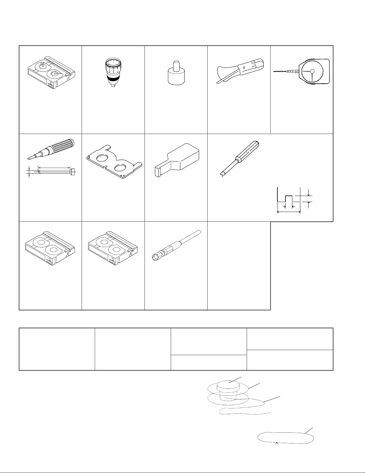
4. MECHANISM ADJUSTMENT JIGS AND PARTS
4-1. Mechanism check adjustment jigs
1. PB-use cassette
Torque meter
2. 9DASD-1015
3. DB
* 1mN·m/1.5mN·m
50 or more
ø2
No. 0 cross-bit
No. 00 cross-bit
1. Torque screwdriver
150mN·m
2. JiGTD1500RTDH
3. CB
1. Torque gauge
2. JiGTG0045
3. CN
*
For use in VS-REW wind-
ing torque measurement.
1. Master plane
2. 9EQMP-VLPD1
3. CL
* For checking reel base
height.
1. Torque gauge head
2. 9EQTGH-DH5000
3. BW
* For use with the torque
gauge listed left.
1. Height adjustment jig
2. 9DAHG-PD1
3. BZ
* For height adjusting.
<Note: The entries of list>
1. Tension gauge 4N
2. JiGSG0400
3. BK
* For measurement of
pinch roller pressure.
1. Height adjustment
screwdriver
2. 9EQDRiVER-DH5
3. BC
*
For guide roller adjustment.
Configuration
1. Name
2. Part No.
3. Code
* Model, Uses Remarks
1. Dial tension gauge
2. 9DAPTG-10-10W
3. CA
* PTG-10
*
For Tu guide adjustment.
*
For T roller adjustment.
*
Bit shape (see figure below).
Tolerance ± 0.1
2
1.4
Tip thickness 0.5
3
<Miscellaneous>
(1) Slide caliper
(2) Precision screwdrivers
1. Alignment tape – ( I )
2. VR3-GAZXS
3. CF
*
For tape running
adjustment.
1. Alignment tape – ( II )
2. VR3-JPZQS
3. CG
*
For SW point adjustment.
* 90ADVC-TAPEPAL can
use, too.
1. For hexagon nut
opposite side 3mm bit.
2. 95CM22001
3. BL
* For S guide hexagon
nut installation.
(Phillips head and slotted)
(3) Radio needle-nose pliers
(4) Tweezers
4-2. Parts for regular periodic inspection and maintenance
1. Oil
Cosmo Hydro HV22
2. 9EQ-Oil-HV22
3. AE
* Cosmo Petroleum K.K.
1. Cleaning paper
2. JiGDUSPER
3. AP
* DUSPER ∑ (SIGMA)
(Ozu Co., LTD.)
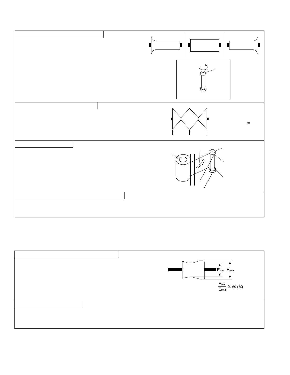
<How to make jigs for mechanism checking and adjustment>
(1)Reel hub for back tension measurement (Fig. 1)
1) Obtain a commercially available cassette tape reel hub.
(Disassemble the cassette tape and remove the tape from
the reel hub.)
2) Paste one end of a string (about 20cm long) to the reel hub
with (for example) cellophane tape.
3) Paste the weight of about 0.21N on the upper side reel hub.
(2)String for use in pinch roller snap-fit force measurement (Fig. 2)
1) Obtain an approximately 20cm length of commercially available string.
2) Tie the 2 ends together to form a loop.
1. Grease: Moly Coat
YM-103
2. 99FGREASE-YM103
* Dow corning
1. Screw lock (1401B)
* Three Bond
<Note:
The entries of list>
1. Cleaning liquid:
Industrial-use ethyl alcohol
* Commercially available item
1. Extremely thin cotton swab
* Commercially available item
Weight
Reel hub
Fig. 1
Configuration
1. Name
2. Part No.
3. Code
* Model, Uses Remarks
String
String
Fig. 2
6
VL-NZ10S/H/E
12/9/2016
Published in Heiloo, Holland
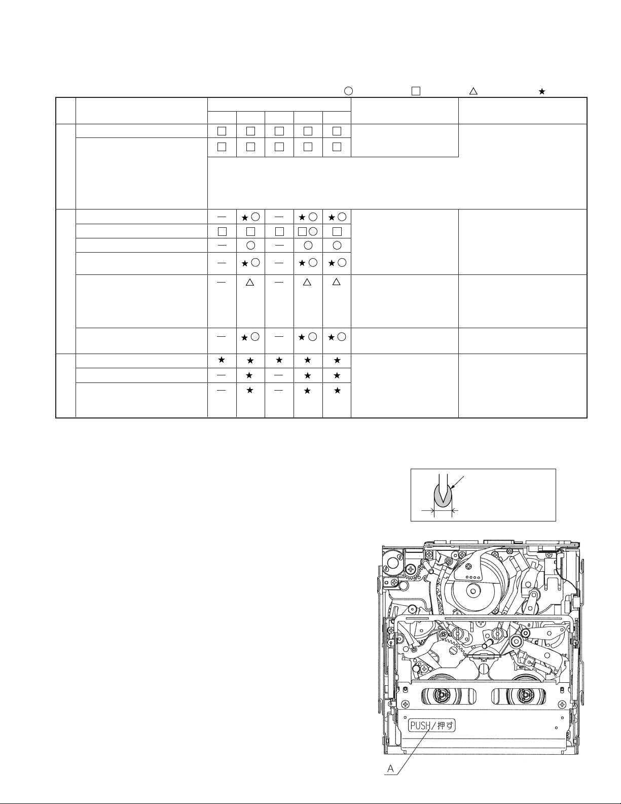
5. INSPECTION AND MAINTENANCE ITEMS AND INTERVALS
In order to keep the mechanical section always in good condition, perform the following inspection and maintenance at regular intervals.
In addition, after repair, perform the following maintenance items regardless of how long the user has been using the unit.
5-1. List of inspection and maintenance items
Inspection and
maintenance location
Tape running section (see section 7-3)
Drum section, Video head
(see section 7-3)
Tape running system
Timing belt
Pinch roller
Capstan motor
Swing arm
S reel base, Tu reel base
Center pulley shaft
Intermediate pulley shaft
Swing arm boss
Drive system
Intermediate gear A shaft,
Intermediate gear B shaft
Loading motor
Mode switch
Abnormal noise
PB · VS/R winding torque
PB · VS/R · loading back tension
Tu reel base ratchet torque
S reel base no-load torque
Performance checks
500 1,000 1,500 2,000 3,000
<Rollers>
• Replace if there is anything abnormal in the rotation, or if there is run-out
(that becomes large).
<Other than the above>
• Clean the section that contacts the tape (especially the lower drum helical
section). Use the specified cleaning liquid.
Time of use (h)
[Oil] Cosmo Hydro HV22
[Grease] Moly Coat YM-103
• • • Replace. • • • Clean. • • • Lubricate. • • • Check.
Symptoms that indicate
need for maintenance
• Block-type noise
• Head hole clogging
• Tape damage
• The tape fails to run.
• The tape becomes slack.
• Block-type noise
• Abnormal noise
• Abnormal noise
• Cannot eject.
• Fails to enter a mode.
• The tape fails to run.
• The tape becomes slack.
• Tape damage
• The play-back image is
abnormal.
[Screw lock] Three Bond 1401B
[Cleaning liquid] Industrial-use ethyl alcohol
Note:
Replace the drum ass'y if the
video head is cleaned but the
envelope still does not appear.
(When the envelope is normal,
refer to "10. USEFUL TIPS".)
• Replace if there is anything
abnormal.
• Lubricate with oil.
[Oil]
Cosmo Hydro HV22
Note:
• Replace if anything is abnormal
(including the noise).
• Replace any part that fails to
perform within the standard.
Remarks
Apply oil to the shaft, then
wipe lightly with a cloth.
5-2. Precautions
(1) When replacing any part, always replace the cut washer that was
removed with a new one.
(2) This mechanism does not have control adjustment. If the control
cannot be set as required, clean and or replace parts.
(3)On the oil
a) Always use the specified oil. (Using another kind of oil can cause
various kinds of trouble.)
b) Always use clean oil, without any mixed-in dirt, to lubricate bearings.
(Using oil with dirt mixed in can cause the bearings to wear or to
stick.)
c) One drop of oil is the amount shown in the Fig. 1, on the point of a
pin.
(4)Perform circuit repair, tape running adjustment, etc. with the cassette
controller assembly attached to the mechanism.
(5)When operating the mechanism separately, apply voltage to the
loading motor. However, the terminal voltage must be DC3V~4V.
(When the mechanism is connected to the main PWB, do not apply
external voltage to the loading motor. It may cause a trouble.)
(Forcing the gears to turn by hand entails danger of breakage.)
If the mechanism is separated from the unit, the capstan motor may rub
and be damaged if spacing under the mechanism is inadequate.
(6)To install the cassette controller, push section A in the Fig. 2. Do not
push anything else.
(7)Do not deform any of the mechanical parts.
Oil
1.5mm diameter or less
Fig. 1
Fig. 2
7
VL-NZ10S/H/E
12/9/2016
Published in Heiloo, Holland
6. MECHANICAL ADJUSTMENTS AND CHECKS
The items discussed here relate to general on-site servicing (field servicing). Adjustments and replacements that require
sophisticated facilities, jigs and technology are omitted.
In addition, in order to maintain the characteristics that the unit has when it is new, not only are inspection and maintenance necessary,
but it is absolutely necessary that, for example, the tape not be damaged, and always use jigs for adjustments that require them.
<Precautions>
(1)Always set the power supply and state of the unit as follows Notes for mechanism adjustments and checks.
AC adapter used, with cassette controller assembly
AC adapter used, without cassette controller assembly (Independent Mechanism)
DC3V, without cassette controller assembly (Independent Mechanism)
(2) When the mechanism is connected to the main PWB, do not apply external voltage to the loading motor. It may cause a trouble.
(3) Always run the tape with the cassette controller assembly attached.
6-1. Checking the playback (recording) winding torque AC adapter used, with cassette controller assembly
(1)Set the torque cassette with the cassette controller assembly attached, then, in SP recording mode (playback mode if a signal has
already been recorded in SP mode on the tape), confirm that the torque on the winding side is within the standard.
<Winding torque standard in record (playback) mode>
(If there is torque ripple, read the center value.)
0.70 +0.4/-0.3mN·m, ripple 0.4mN·m or less
6-2. Checking the rewinding playback (VS-REW) winding torque
AC adapter used, without cassette controller assembly (Independent Mechanism)
(1)Remove the cassette controller assembly, press the DOWN switch, using the
adhesive tape and referring to 8-3, operate in the TEST mode (T01) to rewind,
and set the rewinding playback (VS-REW) mode.
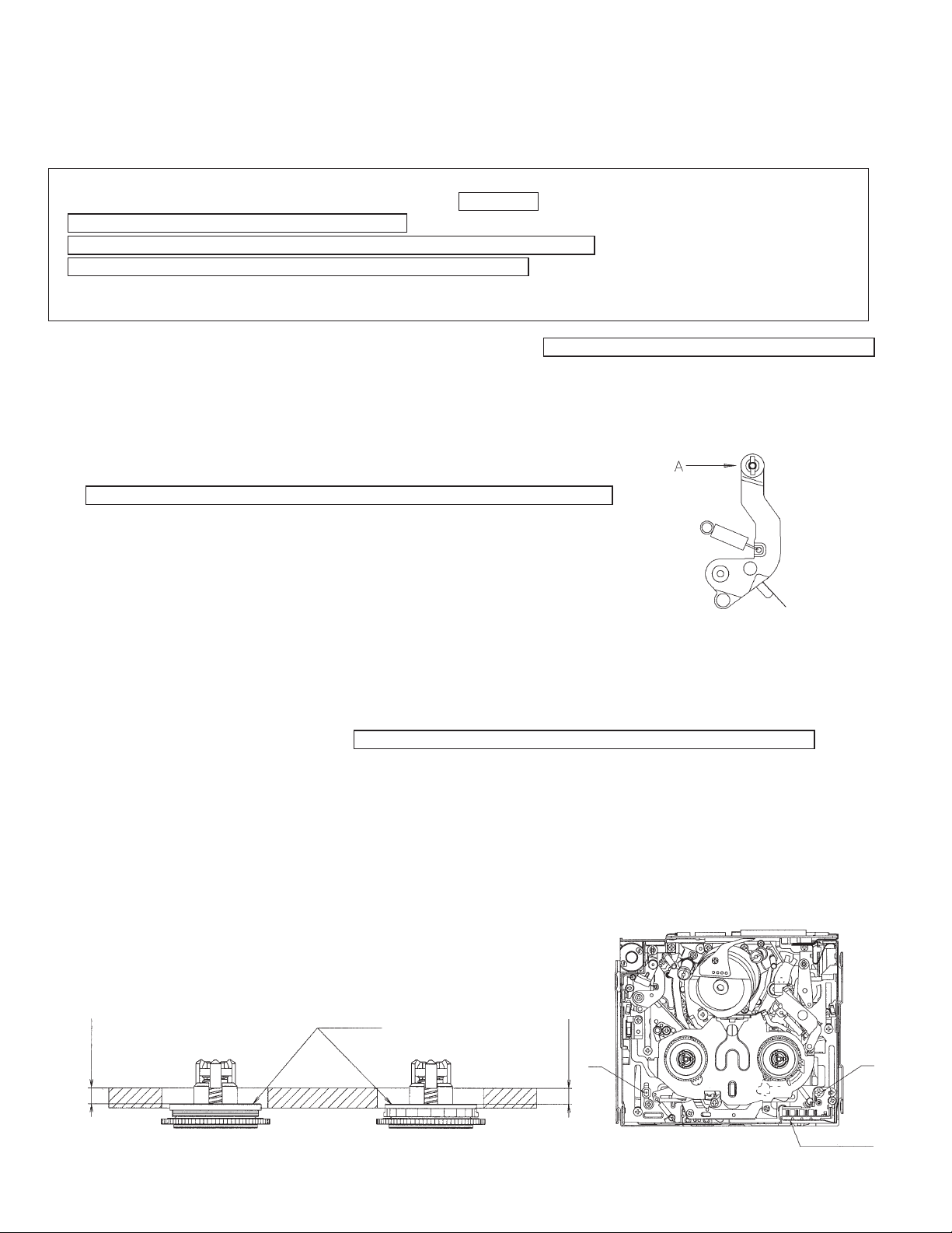
(2)Set the torque gauge on the S reel base, press the front end of tension post with
your finger in the arrow A direction so as to ascertain that the winding torque is
as specified. (Check without rotating the torque gauge.)
<Rewinding playback (VS-REW) winding torque standard>
(If torque ripple exists, read its center value.)
1.6 ± 0.6mN·m, ripple 0.5mN·m or less
(3)After checking the winding torque remove the torque gauge, and remove the
adhesive tape used in item (1) above (refer to 8-3). The STANDBY mode is set
automatically.
Fig. 1. Removal of tension band when
measuring the rewinding playback (VS-REW) winding torque
6-3. Checking of reel base height DC3V, without cassette controller assembly (Independent Mechanism)
(1)Remove the cassette controller assembly (refer to 8-2).
(2)Referring to 8-1, apply DC3V to the loading motor and put the system into playback mode.
(3)Taking adequate care so that the master plane does not contact drum, running parts (guide roller, etc.), or the MIC contacts. Fit
the master plane holes to the 2 guides (A and B) in Fig. 2.
(4)Confirm that the heights of the S reel base reel receiving surface and the Tu reel base reel receiving surface below the master plane
top surface are within the set values, using, for example, a slide calliper (Fig. 3).
When checking the S reel base height, press the front end of tension post in the arrow A direction with your finger to release the
tension band, and then check the height in this state (Fig. 1).
(5)If the height is not within set values, replace the washer under the reel base, and adjust as specified.
Note: After the adjustment, make sure that the reel bases rotate smoothly.
Reel receiving
surfaces
2.4 ± 0.1
2.4 ± 0.1
Reel base height
setting values
Reel base height
Fig. 3
A
setting values
MIC contacts
Fig. 2
B
8
6-4. Back tension torque check and adjustment in record (playback) mode
12/9/2016
Published in Heiloo, Holland
AC adapter used, with cassette controller assembly
(1)Checking
Set the torque cassette (SD-1015), and make sure in the SP record mode that
the supply side torque is within the standard shown below (or in the playback
mode for the tape on which the signal has been SP-recorded).
<Standard>
(If torque ripple exists, read its center value.)
0.7 ± 0.1mN·m
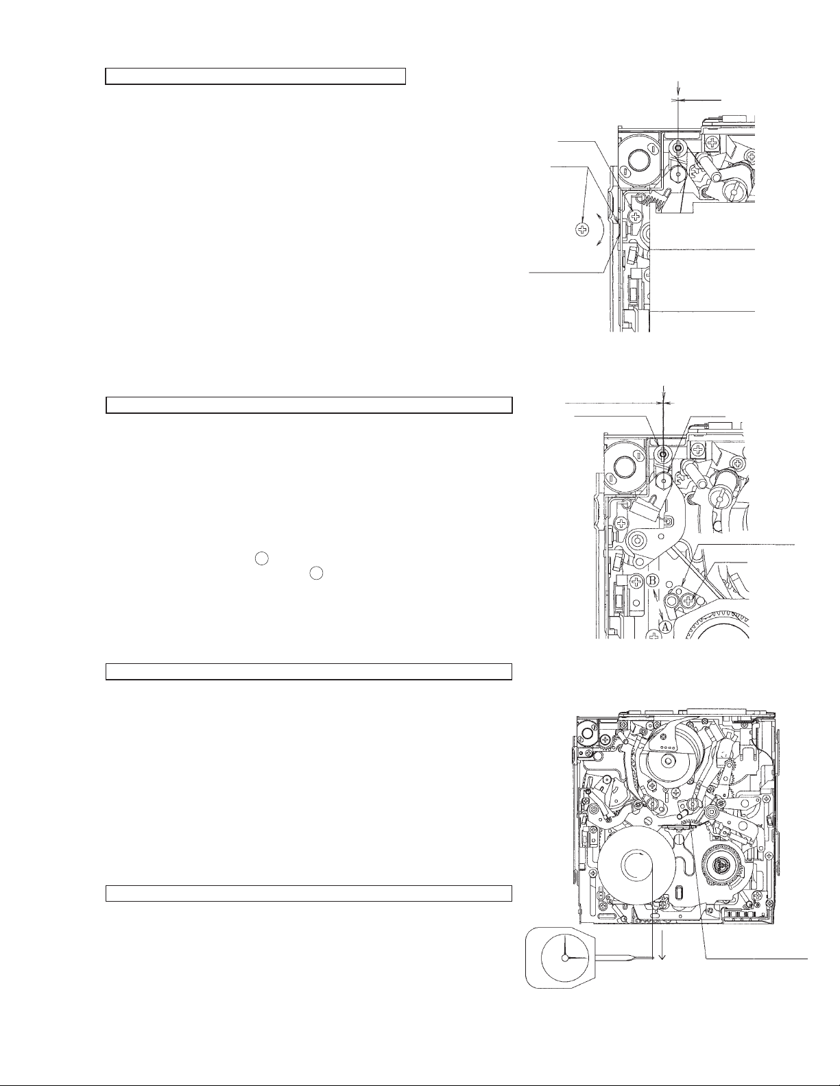
(2)Adjustment (Fig. 4)
If the value is out of standard range, adjust, using the screw 1 shown in Fig. 4.
1. Loosen the screw 2 slightly.
2. Adjust to turning the screw 1. When back tension is too high, turn the screw
1 counterclockwise (CCW).
When back tension is too low, turn the screw 1 clockwise (CW).
3. After adjustment fix the angle with the screw 2. (At this time take care so as
to prevent excessive tightening.) Apply Screw Lock to the screw 1.
<Caution>
Screw tightening torque: 0.04N·m
6-5. Checking and adjustment of tension roller position in
record (playback) mode
DC3V, without cassette controller assembly (Independent Mechanism)
(1)Checking
Before winding the 60-min tape make sure that the tension roller is in the same
position as S guide as shown in Fig. 4.
If not, take out the tape and adjust in the following procedure.
(2)Adjustment (Fig. 5)
1. Set the playback mode without loading the tape.
2. Loosen the screw 3 slightly (to such an extent that the tension band holder
4 can be moved).
3. If the tension roller is inside from the specified position, shift the tension
band holder 4 in the arrow
the tension band holder in the arrow
(Proper shift must be 0.2 to 0.6mm outside from the specified position.)
4. Check the position by the procedure described in item (1) Checking above.
5. If the position is not specified position, adjust again.
direction. If the tension roller is outside, shift
A
direction, and fix with the screw 3.
B
Apply screwlock
Tension roller position (S guide standard)
Screw2
Screw1
CCW
CW
Fig. 4. Check (tape exists)
Tension roller position (S guide standard)
0.2~0.6mm (Standard)
Tension roller
VL-NZ10S/H/E
0 ± 0.3
S guide
Tension band holder 4
Screw 3
6-6. Checking of supply S reel base no-load torque
DC3V, without cassette controller assembly (Independent Mechanism)
(1)Remove the cassette controller assembly, then apply DC3V to the loading
motor and put the system into L. start mode (refer to 8-1).
(2)Move the swing arm toward the Tu reel base side.
Be careful not to cause damage to the gears and other parts in the process.
(Fig. 6)
(3)Set a back tension measurement reel hub on the S reel base.
(4)Using a dial tension gauge, pull the string in the A direction, then confirm that the
tension is within the standard.
<FF back tension standard>
(If the tension fluctuates, read its center value.)
30mN or less
6-7. Checking of loading back tension
DC3V, without cassette controller assembly (Independent Mechanism)
(1)Remove the cassette controller assembly, then apply DC3V to the loading
motor and put the system into L. start mode. (refer to 8-1)
(2)Move the swing arm toward the S reel base side. Be careful not to cause
damage to the gears and other parts in the process. (Fig. 7)
(3)Set a back tension measurement reel hub on the Tu reel base.
(4)Using a dial tension gauge, pull the string in the A direction, then confirm that
the tension is within the standard.
Fig. 5. Position adjustment
(tape does not exist)
Move the swing arm
A
toward the Tu reel
base side.
Fig. 6. S reel base no-load torque
measurement method
9
VL-NZ10S/H/E
12/9/2016
Published in Heiloo, Holland
<REW back tension standard>
(If the tension fluctuates, read its center value.)
15 ± 12mN
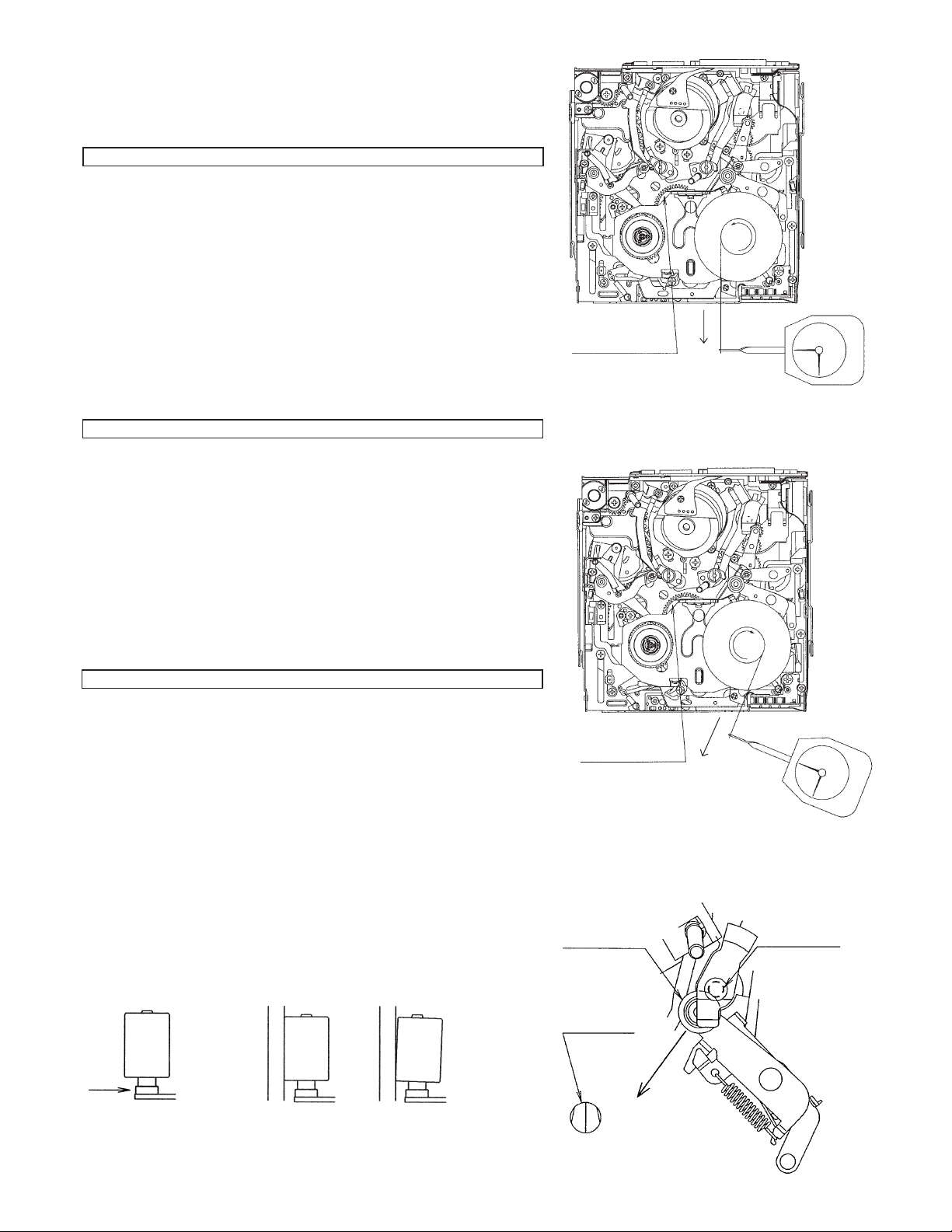
6-8. Checking of winding Tu reel base ratchet torque
DC3V, without cassette controller assembly (Independent Mechanism)
(1)Remove the cassette controller assembly, then apply DC3V to the loading
motor and put the system into standby mode. (refer to 8-1)
(2)Move the swing arm toward the S reel base side.
Be careful not to cause damage to the gears and other parts in the process.
(Fig. 8)
(3)Set a back tension measurement reel hub on the Tu reel base.
(4)Using a dial tension gauge, pull the string in the A direction, then confirm that
the tension is within the standard.
<Winding Tu reel base ratchet torque standard >
(If the tension fluctuates, read its center value.)
100mN or less
6-9. Checking of rewinding playback (VS-REW) back
tension
DC3V, without cassette controller assembly (Independent Mechanism)
(1)Remove the cassette controller assembly, then apply DC3V to the loading
motor and put the system into rewinding playback (VS-REW) mode. (refer to
8-1)
(2)Move the swing arm toward the S reel base side.
Be careful not to cause damage to the gears and other parts in the process.
(3)Set a torque gauge on the Tu reel base.
(4)Turning the torque gauge to counterclockwise (1 turn for 3 seconds), then
confirm that the torque is within the standard.
<Rewinding playback (VS-REW) back tension standard value>
(If the tension fluctuates, read its center value.)
0.70 +0.6/-0.3mN·m
Move the swing arm
toward the S reel
base side.
A
Fig. 7. Loading back tension measurement
method
6-10.Checking of pinch pressing force
DC3V, without cassette controller assembly (Independent Mechanism)
(1) Set the pinch roller pressing force measuring thread on the pinch lever
(position A , Fig. 9).
(2)Set the mechanism to the playback mode, press the pinch roller against the
capstan shaft.
(3)Fit the tension gauge to the pinch roller pressing force measuring thread, pull
in the arrow B direction shown in Fig. 11 to separate a little the pinch roller from
the capstan shaft.
(4)Gradually return the pinch roller, and when the pinch roller contacts parallel
the capstan shaft, read the value (see Fig. 10) to make sure that the value
conforms to the standard shown below.
<Standard>
1.8 +0.3/-0.5N
<Caution>
After making this measurement, quickly release the system from playback
mode and remove the pinch roller from the capstan shaft. (If the pinch roller
is left fitted onto the capstan shaft for a long time, the pinch roller will be
deformed.)
A
OK
NG
Move the swing arm
toward the S reel
base side.
A
Fig. 8. Winding Tu reel base ratchet torque
measurement method
Pinch roller
Right guide
Capstan shaft
B
Fig. 9
Fig. 10
Fig. 11
10
7. TAPE RUNNING ADJUSTMENT
12/9/2016
Published in Heiloo, Holland
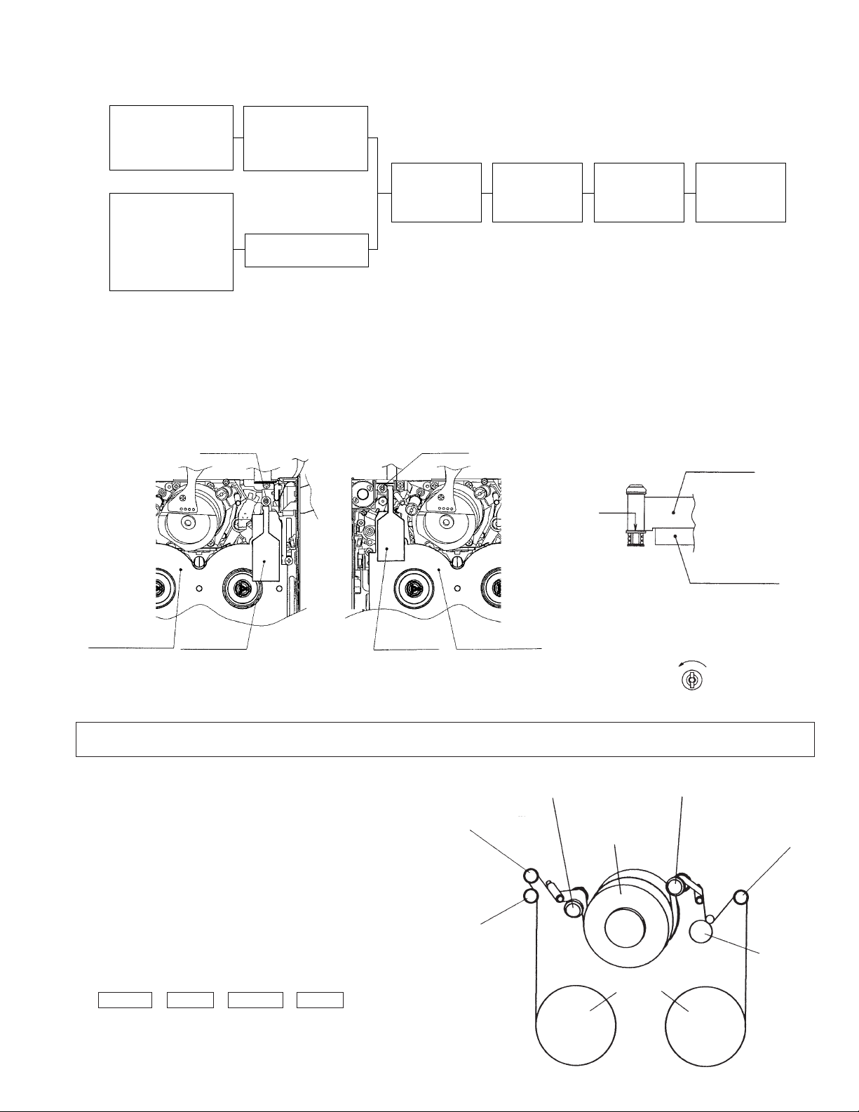
7-1. Adjustment locations
VL-NZ10S/H/E
<Replacement parts>
· T roller, arm
· Tu guide, arm
· Slide chassis
<Replacement parts other
than those shown above>
· S guide
· Pole base
· Guide roller
· Drum assembly
· Capstan motor, etc.
Adjust the height of only
replaced parts with the
adjusting jig.
Adjustment procedure 7-2
Height presetting is not
necessary.
Cassette controller
installation
Running adjustment preparation
Adjustment
procedure 7-3
Running rough
adjustment
Adjustment
procedure 7-4
Running final
adjustment
Adjustment
procedure 7-5
7-2. Running height adjustment
· After replacement of T roller or Tu guide adjust the height . (Adjust only the replaced parts.)
· After height adjustment do not turn the T roller. If crease is found on the tape of Tu guide, remove the crease by rotating.
(As for details refer to the “Running rough adjustment”.)
· After height adjustment of T roller or Tu guide, apply Screw lock to an end of shaft.
(After replacement of S guide apply Screw lock to same point, too.)
Tu guide
T roller
Height setting
jig
Lower edge
fitting
Master plane
Fit height the par on low edge fitting.
After setting adjustment jigs, turn T roller
counterclockwise to 315°.
Master plane
Height setting
jig
Height setting
jig
Master plane
7-3. Preparation for tape running adjustment
Meters, jig… Oscilloscope, Adjustment remote control, Height adjustment screw driver, Alignment tape (for tape running
adjustment, for switch point adjustment), Master plane, Height adjustment jig.
<Method and description>
(1)Clean the tape running surface (especially, adequately clean
the drum surface and the lower drum helicam surface).
(2)Attach the cassette controller.
(3)Connect an oscilloscope to each TP on the relay circuit board.
(4)Turn the AC adapter power ON.
(5)Using the adjustment remote control unit, put the system TEST
mode T-05.
(6)Replay the alignment tape for running adjustment, and make
sure that the tape is running in the SP mode.
(7)Check the oscilloscope playback envelope, then, at +1/4 shift
and -1/4 shift, check whether all of it is flat. If it is not, perform
the following adjustment so that it becomes flat.
(Each time you push the PLAY key, the shift will change;
+1/4 shift → Normal → -1/4 shift → Normal , in order.)
Sup guide roller
Tension roller
Drum
S guide
Tu guide roller
Tu guide
Pinch roller
Reels
11
VL-NZ10S/H/E
12/9/2016
Published in Heiloo, Holland
7-4. Running rough adjustment
(With cassette controller)
1) Su, Tu guide roller height adjustment
<Method and description>
(1)Loosen the guide roller lock screw, then tighten loosely so that
the roller turns easily.
(2)Replay an alignment tape, and adjust the Sup, Tu guide roller
so that the envelope sides of entrance and exit are flat.
(3)Perform ± 1/4 shift, then, as in the above case, adjust until the
envelope becomes flat.
* If running is difficult for the entrance changed, turn the T roller
to counterclockwise 180°. (refer to Fig. 1)
2) Check of V/SR envelope wave form
<Method and description>
(1)Confirm that the envelope waveform peaks in V/SR mode are
uniform.
(2) If they are not uniform, fine-adjust the guide roller and the Tu
guide.
3) Check of tape wrinkles
<Method and description>
(1)Check that the tape is not distorted between the Tu guide and
pinch in the PB mode and the V/SR mode.
-If crease is found, make an adjustment in the range of ±180°.
-After adjustment apply Screw Lock.
NG
±1/4 shift ±1/4 shift
Entrance side
Turn to 180°
Exit side
Normal
T roller
Fig. 1
Adjust so that A B.
A
Pinch roller
B
Wrinkles
Tu guide
Deformation
Deformation
NG
•
•
4) Check the rising time of the envelope wave form
<Method and description>
(1)Check the rising time of the envelope when switching from V/SR mode to PB mode. (Within 5 sec)
(2)Check the rising time of the envelope when switching from STOP mode to PB mode. (Within 5 sec)
7-5. Final running adjustment
(With cassette controller)
1) Adjustment of Sup and Tu guide roller height
<Method and description>
(1)Perform ± 1/4 shift, then if the envelope wave's ratio of MAX.
to MIN. are 60% or less, adjust again the height of guide roller.
(Refer to Fig. 2)
(2)Finally adjust the lock screw of Sup and Tu guide roller.
(3)Once perform unloading and then loading to set the PB mode,
and make sure that the envelope waveform does not change.
2) Adjustment of playback SWP
<Method and description>
(1)Playback the alignment tape for switch point adjustment.
(2)Perform SWP automatic adjustment with adjustment remote control.
Fig. 2
* When replacing the mechanism and drum, adjust the phase and equalizer using the adjustment remote control.
(Refer to "9. ADJUSTING THE ELECTRICAL CIRCUITS".)
12
VL-NZ10S/H/E
12/9/2016
Published in Heiloo, Holland
8. MECHANICAL SECTION ASSEMBLY AND PARTS REPLACEMENT
(DISASSEMBLY AND REASSEMBLY)
Mechanical section disassembly and reassembly are explained in this section.
For removal of the cabinet, etc., refer to 3. DISASSEMBLY OF THE SET.
<Precautions>
1. Always replace cut washers that have been removed, for example in parts replacement, with new ones.
When reassembling, be careful not to allow screws, washers or foreign matter to enter. They can cause mechanical misoperation.
2.
3. Use the cleaning liquid, oil, grease and screw lock that are specified below. Use of any other kind can cause mechanical
misoperation.
Oil: Cosmo Petroleum : Cosmo Hydro HV22 Screw lock: Three Bond :1401B
Grease: Dow Corning : Moly Coat YM-103 Cleaning liquid: Industrial-use ethyl alcohol
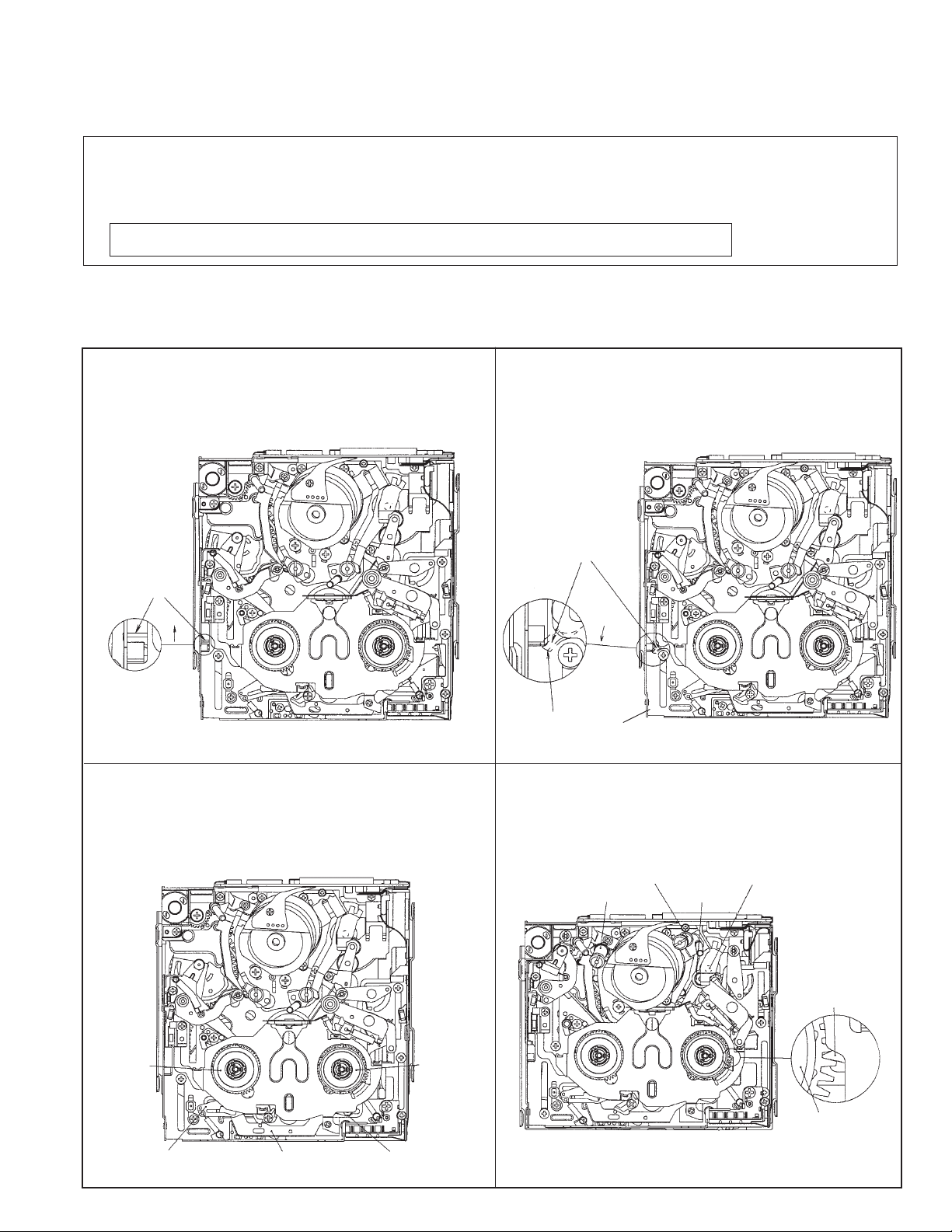
8-1. On the mechanical modes
When operating the mechanism separately, apply DC3~4V to the loading motor.
(When the mechanism is connected to the main PWB, do not apply external voltage to the loading motor. It may cause operational problems.)
(1)EJECT mode
The mechanism position to take out the cassette where the
EJECT lever is extremely shifted in the A direction. (It is
impossible to lock the cassette controller assembly in this
mode.)
EJECT lever
A
EJECT mode diagram
(3)LOADING START mode
This is the mode where the tape is wound around the winding
reel when a cassette with visible wind start leader tape is
loaded. (The brake shifter moves to the left, the S main brake
is separated from the S reel base and the Tu main brake is
separated from the Tu reel base.)
(2)STANDBY mode
The mechanism position to set the cassette where the slide
chassis is at the farthest position from the drum and the
EJECT lever is in counterclockwise rotated position (position
where the cassette controller assembly can be locked).
EJECT lever
Rotation
It is hardly seen since
it is concealed with
slide chassis.
Slide chassis
STANDBY mode diagram
(4)REWINDING (VSR) mode
The mechanism position to rewind the tape (fast rewinding
playback). The S and T pole base is pressed, the pinch roller
is pressed to the capstan shaft, the brake shifter VSR brake
section engages with the Tu reel base gear.
T pole base
S pole base
Capstan shaft
Pinch roller
S reel base
S main brake
Brake shifter
LOADING START mode diagram
VSR brake section
Tu reel base
Tu reel base
Tu main brake
REWINDING (VSR) mode diagram
13
VL-NZ10S/H/E
12/9/2016
Published in Heiloo, Holland
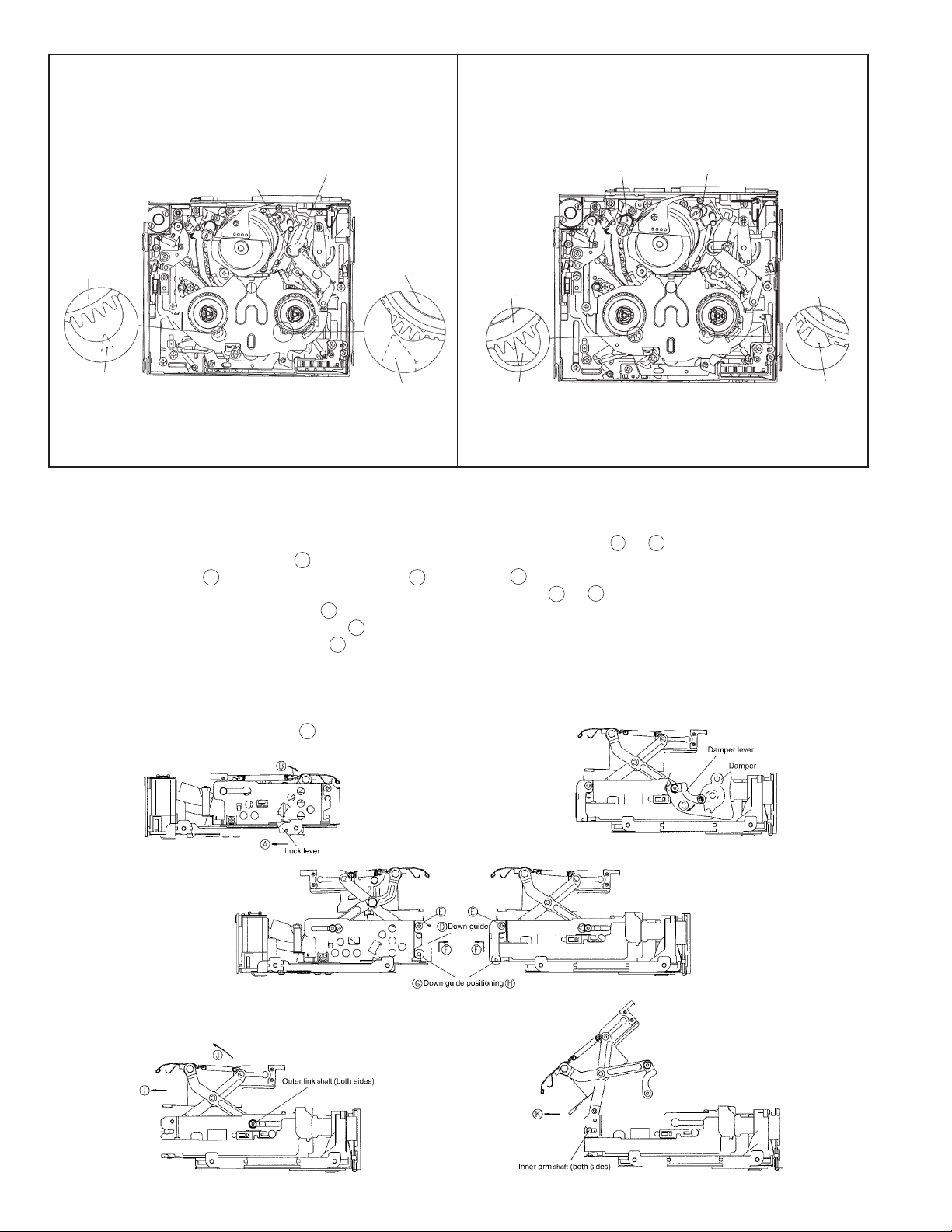
(5)PLAYBACK (RECORD, FF, VSF) mode
The mechanism position for playback, record, FF and fast
feed playback.
The pinch roller is pressed to the capstan shaft, and the S/Tu
main brake is separated from the S/Tu reel base.
Pinch roller
S reel base
S main brake
Capstan shaft
Tu reel base
Tu main brake
(Not visible)
(6)STOP mode
The system is in the STOP (Rec Lock in CAMERA mode)
position; the S and the T pole bases are snap-fitted to the drum
base, the S brake is in contact with the S reel base, and the Tu
brake is in contact with the Tu reel base.
S pole base
S reel base
S main brake
T pole base
PLAYBACK mode diagram
(RECORD, FF, VSF)
STOP mode diagram
8-2. Cassette controller assembly
<Removing>
(1) Apply DC3V to the loading motor to enter the standby mode.
Press the lock lever in the arrow direction to raise the cassette controller. (See Fig. 1; A or B direction.)
(2) Turn the damper lever in the arrow
(3) Remove two screws
, and remove the down guide D in the arrow F direction. (See Figs. 3 and 4.)
E
Take care that the slide chassis is provided with the down guide positioning
(4) Slide the cassette controller in the arrow
and turn the cassette controller in the arrow J direction. (See Fig. 5.)
(5) Slide the cassette controller in the arrow K direction. (See Fig. 6.)
direction to release the engagement of the damper bar. (See Fig. 2.)
C
or
.
H
direction, remove the outer link shaft (both sides) toward the inside of the mechanism,
I
G
Tu reel base
Tu main brake
<Installing>
(1) Apply DC3V to the loading motor to enter the standby mode.
(2) For assembly, reverse the removing procedure (5) thru (2).
Tightening torque of two screws
Fig. 1.
: 40±4mN.m
E
Fig. 3.
Fig. 2.
Fig. 4.
Fig. 5.
Fig. 6.
14
VL-NZ10S/H/E
12/9/2016
Published in Heiloo, Holland
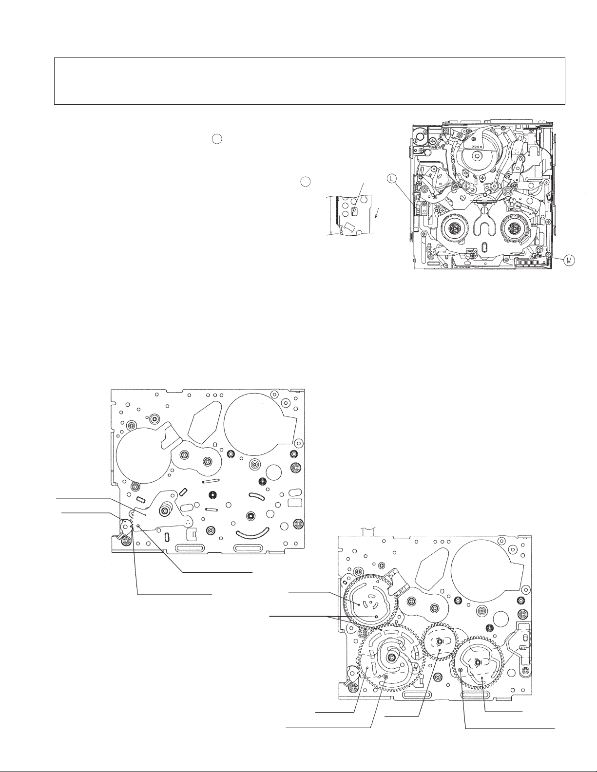
8-3. How to operate with the circuit board without the cassette controller assembly.
In this method, if the procedure is followed incorrectly there is danger of damaging the mechanism and the tape, so except in special
cases, such as when measuring the VSR torque, do not perform this procedure. Normally operate this unit with the cassette controller
assembly attached.
Be sure to follow each caution mentioned.
(1) Apply DC3 ~ 4V to the loading motor to enter the standby mode.
(2) Securely press the movable piece L of the down SW with
cellophane tape or similar to turn on SW. (Take care that the
movable piece turns only in the shown arrow direction.)
Note: To enter REC mode, press the pin of the recognition switch M.
(Unnecessary in other modes.)
(3) Set the test mode (T-01) with the adjustment remote controller
without putting the tape, and the mechanical operation will
become possible with the mode key.
(4) For ejection, remove the tape of (2).
Movable piece
of down SW.
Side view
Rotary direction of
movable
piece
8-4. Phase matching
Fig. 7. LOADING START mode
Referring to Figs. 8 and 9, align the phase for the following parts.
(1) Eject lever (2) Eject control lever (3) Mode SW (4) Main cam (5) Sub cam
Note: Before disassembly, sufficiently check the marker position.
Note: When installing the joining gears, verify that the phase matching holes of the main cam and subcam are aligned to the hole of
the chassis.
Note: After the phase is aligned, turn the mode SW with hand, and verify that it turns nearly one turn.
(After verification, return it to the original position.)
Eject
control lever
Eject lever
Phase matching hole
(for chassis)
Phase matching hole
(for gear)
Fig. 8
Mode switch
Phase matching
mark
Main cam
Phase matching hole
(for chassis)
15
Coupling
gear
Fig. 9
Sub cam
Phase matching hole
(for chassis)
VL-NZ10S/H/E
367
315
363
366
311
312
364
365
421
459
C
F
E
E
T arm control
lever stopper
H/A PWB angle
Center pulley
Ass'y
Drive belt
Intermediate gear angle
sub Ass'y
Intermediate gear
stopper
Intermediate pulley
Ass'y
Capstan FPC stopper
G
G
Phase match check
Enter part of
convexity rear
surfacer
Guide rail sub Ass'y
Phase match check
Guide rail sub Ass'y
(Rear surface)
12/9/2016
Published in Heiloo, Holland
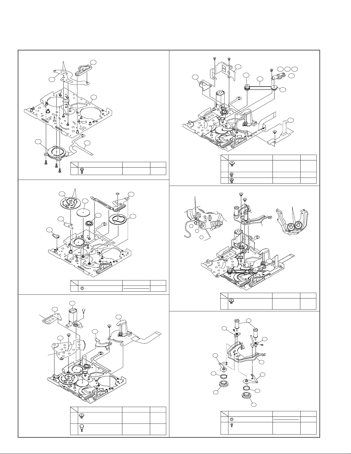
8-5. Reassembly
8-5-1. Reassembly in side of the main chassis.
Note) Numbers before part names are given as a guide to the order of assembly.
As for greasing/oiling/cleaning places refer to the attached drawings (Grease/Oil application side of the main chassis).
1.
2.
Pinch control lever
Mode SW
303
463
A-3
EJECT control lever
EJECT lever
360
Groove grease
A-2
A-1
Main cam
304
302
Pinch drive lever
361
Main chassis Ass'y(Front surface)
301
LM/Mode FPC
465
Item
Tightening torque
A S Tight · M1.4 x L3 70mN·m 3
Cam groove grease
Coupling
gear
370
AHC cam
369
Shifter drive lever
B
305
371
Sub cam
Ass'y
Quantity
4.
C Special screw · 40mN·m 1
Item
M1.4 x L1.6
E S Tight · M1.4 x L4 70mN·m 2
F S Tight · M1.4 x L2 70mN·m 1
Tightening torque
Quantity
5.
3.
T arm control lever
Groove grease
Groove grease
309
Loading lever
B CWø1.2-ø3.0-t0.25 1
Item
Loading motor Ass'y
461
Loading motor
D
306
fitting Ass'y
Slide chassis
C
guide
Capstan motor
462
C
386
Item
C Special screw · 40mN·m 2
D
M1.4 x L1.6
Special screw with step
M1.4 x L6.25
· 70mN·m 1
Tightening torque
Tightening torque
Quantity
Quantity
16
G
Special head screw ·
Item
Tightening torque
40mN·m 2
Quantity
M1.4 x L1.5
6.
Sup pole base Ass'y
S loading arm
Ass'y
307
S pressure spring
395
372
S loading gear
I
451
H
Guide roller Ass'y
454
Tu loading arm Ass'y
H
396
373
Tu loading gear
Item
Tu pole base
452
Ass'y
I
Guide rail
362
308
Tu pressure spring
Tightening torque
Quantity
H CWø0.7-ø2.2-t0.25 2
I Special screw · 5mN·m 2
M1.2 x L1.8
(Tentative tightening)
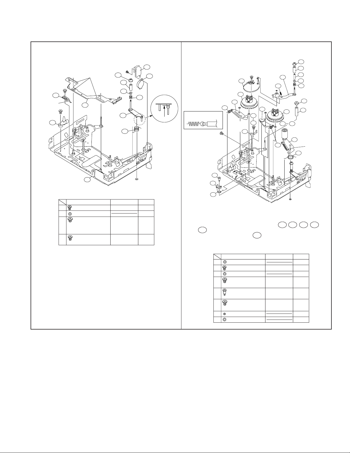
8-5-2. Reassembly in side of the Slide chassis.
428
382
455
384
383
397
351
392
354
456
356
375
374
391
391
357
420
390
385
394
458
457
411
411
415
415
N
N
O
O
L
F
K
M
H
B
H
T roller upper
flange
T roller Ass'y
T roller inner
T roller bottom
flange
Guide adjustment
SPR.
S guide hexagon
nut
S guide sleeve
Tu reel base
Ass'y
Tension arm Ass'y
T arm SPR.
Tension band
Ass'y
S reel base Ass'y
S main brake
Main brake SPR.
Fit the main brake SPR from
above, and close with the hook.
T spring
hanging
ANG
Pinch lever
return SPR.
Pinch lever Ass'y
Grease
Main brake
SPR.
Swing arm release
lever fixing screw
Swing arm
release lever
Swing arm
release SPR.
Tu main
brake
12/9/2016
Published in Heiloo, Holland
Note) Numbers before part names are given as a guide to the order of assembly.
As for greasing/oiling/cleaning places refer to the attached drawings (Grease/Oil application side of the slide chassis)
VL-NZ10S/H/E
1.
Slide adjustment
angle
Grease
376
S cassette stay
K
382
Tu pole
381
383
352
Tu guide
Ass'y
arm
393
Tu guide
arm SPR.
Tightening torque
Note1)
344
J
F
Grease
353
Brake shifter
Ass'y
331
Slide chassis Ass'y
Item
T roller upper
flange
T roller bottom
flange
F S Tight · M1.4 x L2 40mN·m 1
H CWø0.7-ø2.2-t0.25 1
J Special screw · 40mN·m 1
M1.2 x L1
Note 1: Use the No. 00 bit.
K
Special head screw ·
40mN·m 1
M1.4 x L2
Sensor FPC cover
502
466
397
Guide
adjustment
SPR.
H
Quantity
2.
Damper
Spring
Note 1: Take care for scratch and hit mark on 381, 382 , 383 , 384 and
455 . Handle the tension band with care against deformation.
Note 2: After lightly tightening 428 arm area against deformation,
apply screw-lock on the tip of the shaft.
17
Item
Tightening torque
Quantity
B CWø1.2-ø3.0-t0.25 1
F S Tight · M1.4 x L2 40mN·m 1
H CWø0.7-ø2.2-t0.25 2
Special head screw ·
K
40mN·m 1
M1.4 x L2
Special screw with step
L
· 40mN·m 1
M1.4 x L1
Type 2 minuteness
M
40mN·m 1
M1.4 x L1
N CWø0.7-ø1.8-t0.1 2
O Wø1.2-ø2.5-t0.3 2
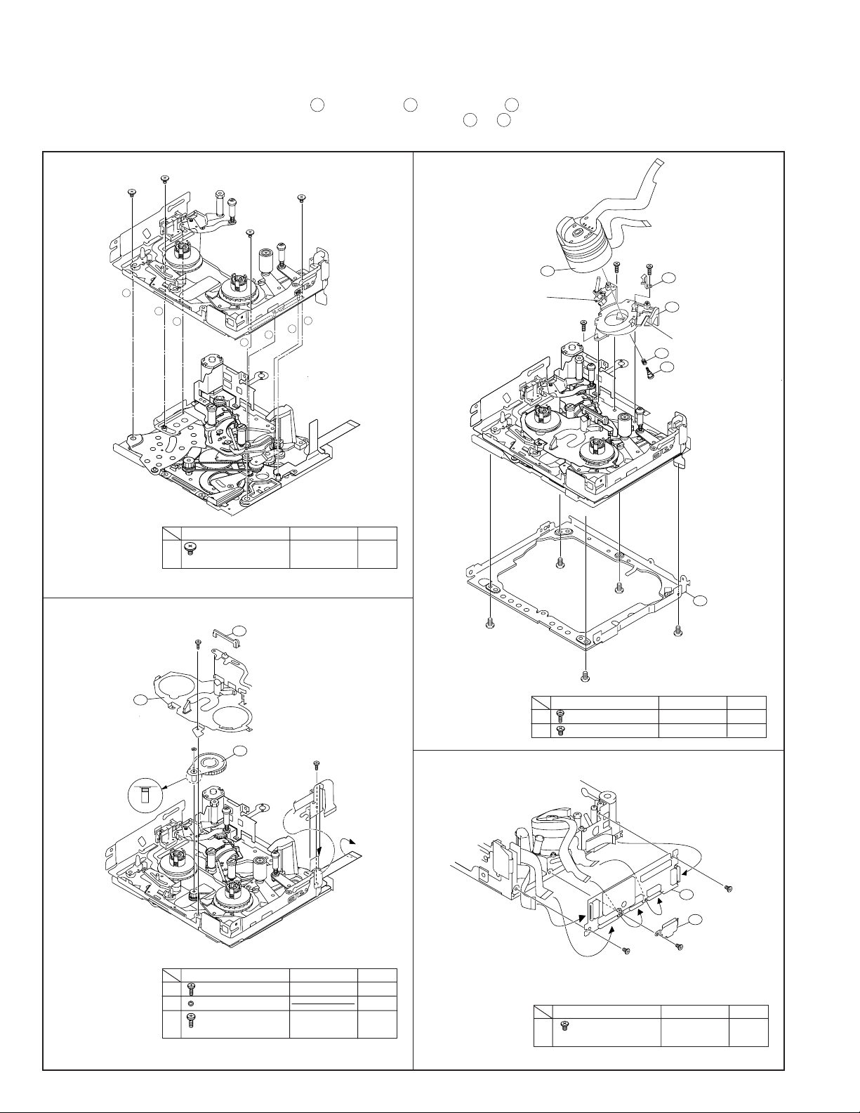
VL-NZ10S/H/E
Grease
(Rear surface,
groove side surface)
470
453
399
398
438
314
A
A
A
F-3
F-4
F-5
F-2
F-1
PB guide SPR.
Drum base Ass'y
Grease
(Front surface, rear surface,
groove side surface)
Tightening torque
50mN·m
Drum Installation screw
Drum fixing SPR
Drum Ass'y
Mechanism fixing angle
Q
501
500
Q
Q
H/A FPC shield plate
Head amplifier PWB unit
12/9/2016
Published in Heiloo, Holland
8-5-3. Main chassis assembly and slide chassis assembly assembling method
(1)Enter the coupling mode. (In this position, the cam groove of the T arm operation lever in the figure is parallel to the side of the main
chassis, and the poll base is slightly moved.)
(2)Insert the slide chassis side operation pins (1 tension arm, 2 Tu guide arm, 3 pinch lever) in the position shown below at the
A
main chassis side, move the slide chassis in the arrow direction, using
into the groove of slide chassis, and install with the 4 screws.
to D as guides, insert the loading lever operation pin
1.
C
C
C
B
A
1
D
Item
C
Special screw ·
C
2
3
Tightening torque
C
Quantity
40mN·m 4
3.
M1.4 x L1.6
2.
355
Reel cover Ass'y
FPC cover
377
P
Swing arm Ass'y
N
313
Oil
Item
A
Tightening torque
A S Tight · M1.4 x L3 40mN·m 1
N CWø0.7-ø1.8-t0.1 1
Type 1 minuteness
P
M1.4 x L1
40mN·m 1
Quantity
18
Item
Tightening torque
Quantity
A S Tight · M1.4 x L3 70mN·m 3
F S Tight · M1.4 x L2 70mN·m 5
4.
Q
Type 2 minuteness
M1.4 x L2
Item
Tightening torque
40mN·m 3
Quantity
VL-NZ10S/H/E
12/9/2016
Published in Heiloo, Holland
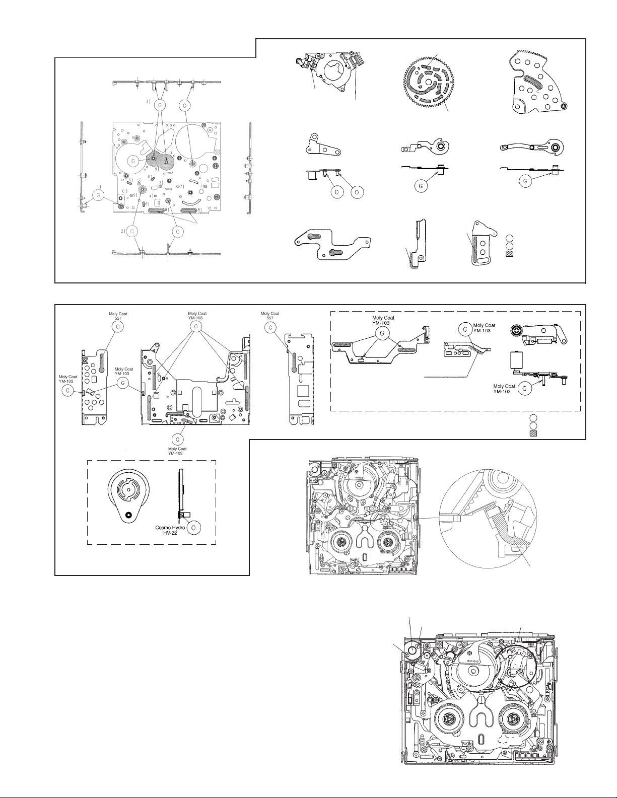
GREASE/OIL APPLICATION
Including groove
side surface
(Applied)
Rear surface · groove
side surface
Drum base assembly
Intermediate gear angle
Pinch control lever
Front surface · rear
surface · groove
side surface
Side of the main chassis
(Applied)
Main cam
S loading arm
Enabled after
Enabled after
assembling
Capstan FPC stopper
assembling
From rear
surface side
From rear
surface side
T arm control lever
Loading lever
Tu loading arm
: Oiling(Cosmo Hydro HV22)
O
: Greasing(Moly Coat YM-103)
G
: Greasing(Moly Coat YM-103)
Swing arm
After joining the main chassis
and slide chassis
8-6. Removing the cassette
(1)Apply DC3V to the loading motor unload slightly.
(2)After the tape is slackened, turn the rotor (lower side of mechanism)
of capstan motor to tighten the tape. (Arrow direction, Fig. 1)
(3) Repeat the operations (1) and (2). After the pole base has been
completely unloaded, ascertain that the tape is not loose.
(4)Finally apply again DC3V to the loading motor, so that the cassette
controller ejects.
(5)Take out the cassette.
Note) DC3V is applied to the loading motor as shown Fig 1. Then, the
mechanism moves in the unloading direction.
Enabled after
Brake shifter
assembling
Slide adjustment angle
Side of the slide chassis
Sensor FPC wiring
Loading motor
Minus pole
Plus pole
Pinch lever
: Oiling
O
: Greasing
G
: Greasing
Part A
Capstan motor rotor rotation direction
(from rear side of mechanism)
Sensor FPC
19
Fig. 1

VL-NZ10S/H/E
12/9/2016
Published in Heiloo, Holland
9. ADJUSTING THE ELECTRICAL CIRCUITS
Before starting the electric circuit adjustment
• The adjustment methods described herein are used, in most cases, when the expendable mechanical parts, including
the video head, have been replaced, at which time the electrical circuits need to be readjusted. Before adjusting the
electrical circuits, make sure that the mechanism works properly (i.e., the mechanism is properly adjusted). Incase of
the occurrence of any problem to the electrical circuits, be sure to use the specified measuring instruments to locate
the area to which the problem is occurring, and then take the necessary action, including repair, replacement or
adjustment, exactly as instructed in the electrical adjustment methods that will follow.
Do not attempt to make adjustments without using the proper measuring instruments.
• This machine is configured so that the electrical circuits inside its PWB unit are composed, for the most part, of highdensity, small surface-mounted component parts for downsized machine body.
To perform repair service or parts replacement, do so using a soldering iron, but in as short a time as possible; this is
because surface-mounted component parts are generally so small in size and susceptible to heat, as compared with
the large discrete parts used in TV sets, desk-top video decks, etc., that attempting to heat their electrodes for a longer
time than is necessary with a soldering iron may result in their becoming defective.
This applies particularly when replacing the laminated chip capacitors.
For this purpose, ceramic soldering irons with a temperature regulator are recommended (iron tip temperature 250°C
and soldering time 5 seconds or shorter).
VL-NZ10S/H/E Specifications of service jigs
No. Connection section Connector REF. No.
1 H/A_PWB–H/A_FPC P306– 80B-B C QCNW-1832TAZZ BV
2 H/A_FPC–Main –SC3301 80B-B CPWBH2876TA01 Product unit use AS
3 Main–Battery Terminal SC900← 20B-B QTANZ0152TAZZ Product unit use AN
4 Main–LCD Panel SC2801–LCD Panel 24 C QCNW-1382TAZZ or BD
5 Main–Inverter PWB SC2802–SC9801 9 N QCNWKA001WJZZ AS
6 Inverter–Lamp Unit SC9802–LAMP Direct connection : High tension caution —
7 Main–Operation PWB SC701–SC2001 6 QPWBH3239TAZZ Product unit use AD
8 Main–AIO PWB SC1202–SC2604 CPWBH3236TA01 Product unit use AX
9 Main–Card PWB SC1204–SC1503 CPWBH3236TA01 Product unit use AX
10 Main–Cam Head SC1201–SC101 CPWBH3236TA01 Product unit use AX
11 AIO–Hot Shoe Unit SC6601← QPWBH3237TAZZ Product unit use AG
12 Power/Snap SW Unit– SC2701← RMiCC0108TAZZ Product unit use AP
Mic Unit
13 AIO–Power/Snap SW Unit SC2601← QSW-Z0379TAZZ Product unit use AW
14 AIO–Zoom/Media SW Unit SC2602← QSW-Z0374TAZZ Product unit use AY
15 AIO–Speaker P602← VSP0020P-918N Product unit use AL
16 Cam Head–Lens SC551← Direct connection —
17 Cam Head–CCD PWB SC2–SC21 QPWBH3225TAZZ Product unit use
18 Cam Head–Turn SW Unit P101← QSW-Z0376TAZZ Product unit use AF
19 Cam Head–Main P103–P1203 12 QCNW-2060TAZZ Product unit use AD
20 TP Jig for Envelope SC3302← 10PB-B N RUNTKA003WJZZ BF
confirmation
No. of pins
New or
Continuation
QCNW-1274TAZZ AZ
Part cord
Price
code
20
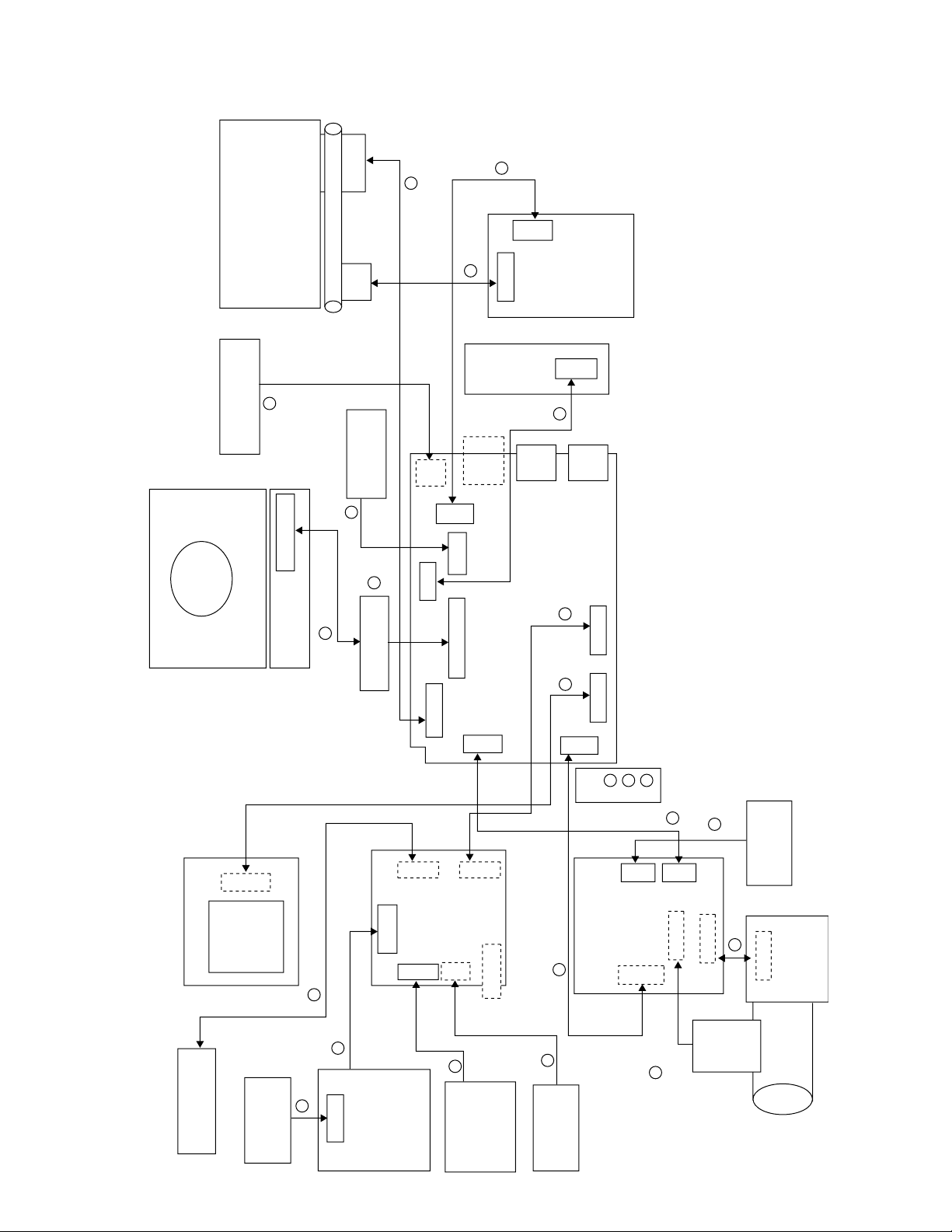
VL-NZ10S/H/E Service jig configuration
Direct connection
Direct connection
TURN SW UNIT
QSW-Z0376TAZZ
10
13
14
5
11
9
9 10
8
18
17
6
8
19
15
CCD PWB
SC2
SC21
LENS FPC
SC551
SC101
P101
SC2604 SC6601
SC1503
SC2602P602
P103
SC1201
CPWBH3236TA01
( , , )
P1203
SC2802
J1401
SC9801
J7401
J3701
SC2001 OPERATION PWB
SC
3302
CAM HEAD PWB
SC1204 SC1202
SC2801
SC3301
SC701
SC900
BATTERY
TERMINAL UNIT
QTANZ0152TAZZ
HEAD AMP FPC
CPWBH2876TA01
P306
HEAD AMP UNIT
MECHANISM
JIG FOR ENV. OUTPUT
RUNTKA003WJZZ
LCD PANEL
LAMP
FPC
PANEL FPC
SC9802
INVERTER PWB
MAIN PWB
CARD PWB
SC1501
CARD SOCKET
HOT SHUE UNIT
QJAKE0094TAZZ
MIC UNIT
RMiCC0108TAZZ
SC2701
POWER/SNAP SW
UNIT
QSW-Z0379TAZZ
ZOOM/MEDIA SW
MENU OPERATION
SW UNIT
QSW-Z0374TAZZ
SPEAKER
VSP0020P-918N
SC2601
J601
3
20
4
2
1
7
16
12
QCNW-2060TAZZ
QPWBH3225TAZZ
AUDIO I/O PWB
QPWBH3237TAZZ
QCNW-1832TAZZ
QCNW-1382TAZZ
or
QCNW-1274TAZZ
QCNWKA001WJZZ
QPWBH3239TAZZ
LENS UNIT
12/9/2016
Published in Heiloo, Holland
VL-NZ10S/H/E
21
VL-NZ10S/H/E
12/9/2016
Published in Heiloo, Holland
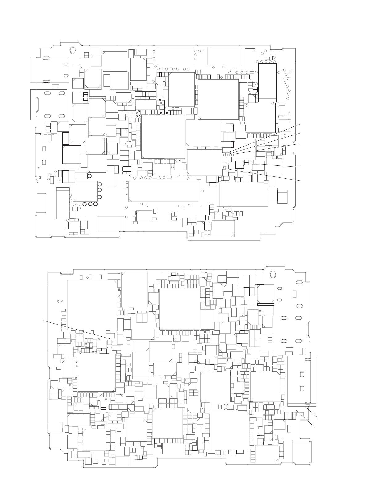
[TEST POINT]
(Wiring board diagram: Main Side A)
TL1476
J3701
J7401
C971
R988
R989
R1477
TL1470
TL1472
TL1478
R1479
FB3703
TL1474
R1481
TL1471
TL1246TL1201
C3708
FB456
TL3321
D2800
TL3337
TL1234TL1236TL1237
TL1249
TL1247
C3719
C3718
R3716 R3758
C3710 C3703 C3706
FB3701
C3701
C465
IC408
C430
C460
TL3320
C2808
C2825
C2801
C2807
R2821
D2802
R2839
R2837
C3716
R3745
C463
IC407
Q2804
C2817
TL1217
C3717
R3746
R415 C462
C2827
C2828
C2826
R2856
R2842
L2803
R2840
R2810
R2806
R2805
Q2803
R2836
R2834
SC1204
TL3776
R3713
IC3701
C2823
IC2803
IC2801
C2829
TL2824
TL1227
TL2803
TL2801
L3701
R2851
TL2825
TL3774
R3710
C2804
C2805
L2801
TL2802TL2804
C2803
R2811
C2800
R2852
TL2826
FB2800
R2807
TL3773
TL1202
TL3775
R3703
C3707
R3709
R3743
R3704
R3744
FL3702
R3707
R3706
R3705
R3708
C3704
TL3339
R3717
R3701
C3702
R3718
R152
R153
C165
C155
Q3701
L151
L2800
IC2800
Q2802
R2813
C2814
C2812
R2815
R2825 R2824
R2804
R2841
R2853
R2830
R2808
R2844
SC2801
TL8827
R2854
R2855
R2819
R2818
R2823
C2818
C960
R991
C961
Q909
R995
C937
C953
R982
Q903
C970
R987
Q906
R956
R993
L916
Q907
C972
L917
C974
L915
C991
C930
TL1473
R1474
CP2
TL2829
TL2831
TL2832
SC2802
TL2836
R2831
R2835
CP3
TL902
CP1
SC900
TL901
TL2833TL2834
TL2830
R2860
R2857
R2858
Q2805
FB2801
R2833
C2819
Q2806
IC2802
R2863
R2862
C2831
C2821
T900
Q905
L907
C938
C931
C973
R970
R999
C932
Q900
L901
C933
C982
L918
Q908
C981
L923
Q911
R951
C992
C990
L922
Q7401
L2804
TL905
TL906
TL904
TL903TL900
SC701
R411
R950
FB7401
R7401
R403
L900
R412
R996
C980
R990
L1601
C451
R443
IC405
R441
R440
C405
C450
C404
R416
R407
R410
Q7402
Q7403
R7403
C7414
C7413
R7419
C7403
D7401
R7417
R7420
D7402
R7415 R7416 R7413
R7418
C7401
L7400
C403
C402
C401
R401
R463
R402
TL420
TL3332
TL3330
TL3331
TL3325
TL3328
TL3317
R3491
TL1245
C1608
TL1216
C1605
C1610
TL1206
C1611
C1617
IC1602
C1604 C1603
TL1242
C407
C452
R446
D404
D403
R442
C447
R437
R436
C435
FL403
TL405
TL407
R429
R435
R438
R467
R409
TL404
TL401
C424
R7402
R414
C412
C7404
R7423
R7422
C7405
R7424
C7402
R7425
C7417
C413
C425
C7400
C472
C420
C473
L471
R477
C474
D472
D471
R478
TL3326TL3313
TL3329
SC1202
TL1214
TL1210
TL1244
TL1243
TL1209TL1240
TL1238
R3748
R3752
R3756
R3757
Q3702
R3754
R3753 R3755
C3709
R406
C417
TL415
TL414
R405
C477
FB408
TL421
R468
R428
C415
IC3702
L403
TL416
TL403
TL417
R413
TL406
C423 C478 R404
C432
C414
R471
C411
R462
IC452
TL402TL418
C421
R418
R432
C475
C476
R431
C410
C456
TL3323
X401
TL3301TL3322
C418
C419
TL3324
TL3333
SC3301
TL3314
R3492 R3493
TL3315
IC3405
C3462
R3495
TH2800
TL3316
TL3318
C2830
R2859
R2861
TL1205
R2829
R2822
TL1254
TL1252
TL1256
C3715
C1201
TL1267TL1257TL1253
TL1260
TL1261
TL1264
C167
R158
Q1200
R3741
TL1262
C157
R2803
C2815
C166
C2806
IC151
C158
TL1269
C2810
C2811
C2809
L2802
C2816
C154
C159
R2802 R2801
C2824
TL1258
SC1201
TL1271
C160
C161
Q2800
R2814
R2812
P1203
C2802
D2801
TL1266
TL1203
TL1259
TL1265
TL8828
TL1223
TL1263
TL1270
TL1222
TL1224
TL1225
R155
C164
TL152
C163
TL2803(G OUT)
P153
R154 C162
R159
C153
Q4471
R4478
R4477
R4473
C1402
TL151
R4475 R4474
C1431
DAC full-scale
TL2802(R OUT)
DAC full-scale
TL2804(B OUT)
DAC full-scale
TL2800
COMMON PULSE
TL2801(C OUT)
COMMON PULSE
IC3703
R1200
R3702
R3742
C3711
R3740
R157
TL1268
IC152
C156
R156
TL2800
Q2801
R2820
R2809
C2813
C2822
(Wiring board diagram: Main Side B)
C212
R245
TL207
TL7800
VCO free-run
C215
TL211
TL210
TL212
C218
C217
C220
R246
R219
C4465
R4468
C4464
Q4462
R4465
R4464
C4461
R4469
IC4461
R4454
D4452
C4454 R4456
L4451
X4451
R4453
C4451
D4451
Q4431
TL4417
R4451
C4485
L4481
Q4481
R4486
C4483
C4482 R4485
R4489
R4487
Q4483
C1441
C1411
R1425
C1439
R1419
R4467
R4460
C4466
FB4461
C4427
C4423
C4424
C4422
C4420
C7846
C7845
C1440 R4488
Q1401
C1406
R1402
Q1402
C4463
TL4433
TL4434
TL4416
Q4482
IC1431
IC202
TL208
TL209
C214
R4463
TL244
Q4461
R7843
R7851
R4494
TL4428
C4462
R4462
C7837
C7842
TL4429
R4461
R7841
C4431
C4432
R4495
C7844
TL4425
TL4426
R7847
R4415
C4411
C4405
R4404
R4405
R4406
R4422
R4423
Q4432
C4481
R4437 R4436
R1441
R1440
C1436
C1438
R1442
R1456
R1454
C1404
C1409
R1408
R1415
IC1401
C1405
C1407
Q1404
R1424
D7800
TL4424
C7815
IC4401
R4407
C1437
Q1434
TL1431
C1412
TL246
TL243
TL4421
C4436
C1408
TL1420
C201
FB201
TL202
C202
TL203
C208 C207
C210 C204
C211
FB203
C203
TL250
C213
TL248
C4403
C206
TL7800
TL249
C7816
TL4440
R7852
R4403
L7801
R7857
C7843
C7813
R7856
TL4436
R7860
R4414
R7827
R7859
C4429
C7802
R7803
R7804
R7805
R7802
R7801
R7800
C4425
C4421
C4402
L4401
C4413
C4417
C4410
C4419
TL4415
IC4472
TL4414
FB4402
R4401
C4435
R4435
C4404 L1431
R1431
C1433
R1433
Q1432
R1438
R1434
C1432
R1432 C1434
R1439
L1404
C1413
R1452
R1437
R1455
C1435
C1410
L1402
C1414
C1416
C1418
R1404
C1417
R1421
R1403
R1462
R1461
Q1403
R1413
R1414
Q1405
R1423
C1415
R1422
FB204
TL4441
TL4437
TL4439
R7854 R7855
C7801
C7803
L7800
C7800
Q1433
R1436
C3456
Q1901
FB202
R1904
R7808
TL3334
C3454
C205
TL4438
R7810
R7811
R7809
R7806
C4401
Q1431
R4402
Q3405
TL1248
TL412
Q705
R771
R740
R797
R747
R744
C704
R735
R720
R737
R729
R799
R741
R725
R738
R736
R733
IC201
R731
C727 C732
IC708
C733
R780
C701
C702
R703 R704
C706
TL1235
R708
IC704
C712
L701
TL1251
R755
R706
R710
R730
C721
IC705
IC702
IC703
X701
C715
R7812
R7814
C3455
R3451
L3405
L3402
R3494
L3404
TL3319
IC3404
R3497
IC3403
R3469
R3457
R3411
R3412 C3466
TL3335
C3458
C3451
R3471
C3452
R726
IC707
R727
C738
TL790
D701
D703
C3465
FL3401
FL3402
R3406
R3407
C3410
R3409
C3409
C3408
R3414
R3413
R3410
TL3336
C3411
C3414
C3420
C3417
C3419
C3421
TL3401
C3423
C3481
R3423
R3462
R3463
C3475
R3468
IC3401
TL3403
TL3406
R3436
R3435
C3430
C3429
R3480
C3471
R3490
R3481
C3474
C3436
C714
R7813
R7807
R1435
C3457
R3452
R732 R759
R724
C735
R782
Q3401
C3443
C3413
C3434
C3444
IC3402
R739
C718
R796
R714
R772
R723
C731
TL798
IC701
C734
R711
R781
R716
R713
R719
Q701
Q702
C705
R1998
C1900
R1995
R1994
C703
C3390
R3496
R701
R1717
TL3327
R3489
R3442
R1726
Q3406
C3401
R3401
L3401
C3402
C3442
C3405
R3430
C3403
R3404
C3412
C3406
C3415
R3415
C3416
C3418
C3476
C3477
C3424
C3426
C3433
R3424
R3425
R3482
C3431
R3437
R3422
R3427
C3432
R3446
C3479
C709
C716
C711
R712
R709
R728
R743
R742
R717
R757
C729
R800
R702
R1910
R1908 R1909 R1956
Q1907
Q1902
R1903
L1702
C1728
Q1701
R1719 R1728
R1718 R1727
FL3403
R3418 C3478
R3417
R3416
R3470 C3467
C3470 R3478
R3472
R3420
R3473
R3419
R3421
R3429
C3428
R3432
R3487
R3486
R3428
R3488
R3402
TH3401
C713
R722
R745
C744
C741
C1922
R3454
C3425
Q703
R762
R761
R760
R763
C730
C719
R748
R718 C720
R801
R705
C1911
Q1909
C4701
R1720
R1701
R3479
Q3404
C3473
R3445
C724
R779
R749
R750
C737
C740
R754
TL914
R798
R766
C728
R765
TL799
R764
R767
C726
R751
R756
C725
R746
X702
C745
R802
C746
C742
R707
C743
R1959
C936
TL1908
R1958
R1957
TL1904
Q1908
TL1905
L1701
C1711
C1705
C1706
C1707
C1709
C1713
C1716
C1715
R1712
C1719
R1722
R1721
C1721
R3499
C1722
C722
R753
R752
TL917
TL911
FB900
C949
L902
Q1911
R1925
IC4701
C962
D902
C968
D901
IC706
C967
L920
C723
L921
L913
R985
R986
C959
C965
TL918
C969
L908
C939
C946
L906
Q902
R1999
L905
Q1932
Q1904
C1982
R1918
R1920
R1921
C1921
R1927
R1919
C1910
Q1903
R1917
R1930
R1943 R1944
R1931
R1915
R1929
Q1913
TL1906
C4702
C1906
R1914
C1702
C1701
R1703
R1706
R1705
IC1701
R1716
C1725
R1714
C1723
C1727
C1726
R1715
C963
R1996
Q1914
R1702
R1713
Q1906
C964
R972
R1992
R1913
C1724
L914
Q901
C950
R1997 C1981
IC1902
TL1907
R1940
R931 R930
R934
R935 R937
Q1905
C1703
FB901
TL912
C948
TL913
R1901
R1902
R1941
R1945
R902
R904 R905
R936
C908
C911
C912
C913
C956
L910
L909
R1993
C940
R974
R976
R975
R981
C947
R1950
C983
C902
R903
R933
C909
R939
R938
C910
R940
C914
R1707
R1708
R1709
C1710
C1712
R1710
R1711
C1714 R1911
C1717
C1718
C1720
TL908
L912
C957
C952
L911
C951
R973
C943
C945
R979
Q910
R977
IC901
Q904
C941
C942
R980
C955
L904
C935
C954
R984
L903
C934
R983
TL910
L919
D900
R915
R911 R929
R910
R909
R912
C925
R913 C927
C904
R918
C993
C926
R906
C903
R920
R914
R919
R907
IC900
R941
R943
R947 R953
C915
R942
R946
R948
C917
C916
C924
R968
R1704
R932
R949
R969
C918
R954
R965
C923
C1708
C1704
FB1472
FB1471
R1912
Q1921
Q1920
Q1900
D1900
R1900
R1991
R1990
IC1901
R1989
R1969
C1980
TL3705
TL3702
TL3703
FB3702
TL3704
TL3707
TL1480
TL1481TL1482
TL1484
TL1483
R7427
R7426
R7429
R7428
R994
R917
R924
C905
C928
R923
R926
R927
C906
R962
C907
R928
R966
J1401
C921
C922
R967
C920
C919
R958
C966
R992
R957
R959
R960
R964
FB1475
R952
Q1201
R900
TL3342
R1980
R901
C900
R1986
R1985
R1968
R1983
R1981
R1982
R1984
TL3341
TL1479
R1480
FB1473
TL3340
R1478
TL1477
TL3338
R1476
SC3302
TL1475
TL1475
PCO D/A-Y
TL1477
PCO D/A-C
22
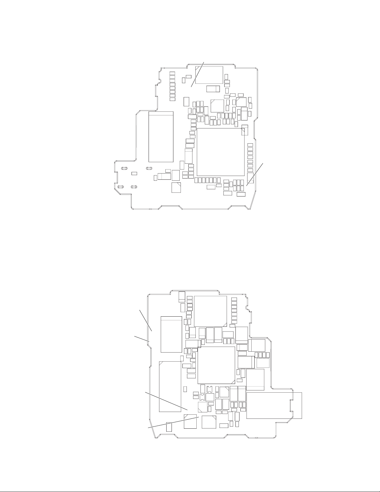
(Wiring board diagram: AIO Side A)
12/9/2016
Published in Heiloo, Holland
TL606
C695
TL607
TL609
TL608
FB603
R2627
R2626
R2625
R2624
R2623
R2622
R2620
R2621
SC2602
C687
D602
TL6607(INT MIC R)
EE level check
Frequency character check
C2611
TL2672
TL2675
TL2674
C2610
TL2671
TL6607
TL2673
0
C6647
R6646
R6648
C6645
C6644
R6651
R6650
R6647
R6649
R6685
C6635
C6646
R6652
C6643
C6639
C6640
C6641
C6681 R6682
R6637
C6648
R6684 C6680
C6634
C6620
TL2679
TL2690
TL2686
TL2685
TL2684
TL2682
TL2681
TL2680
TL2678
TL2677
TL2676
L6601
Q6609
SC2601
D6601
C6682 R6683
C6632
R6634
R6636
C6633
C6619
C6618
C6612
IC6603
R6635
R6633
IC6601
C6613
R6618
R6619
R6617 C6631 R6632
R2629
R2628
C6683
R6631
C6610
R6615
R6616
C6627
C6614
R2630
R2631
R6681
C6649
R6687
C6629
C6601
C6623
R6611
C6658
R6630 C6659 R6688
R6613 C6609
C6606
R6610
Q6601
C6611
R6680 R6607
TL6605
C6625 R6612
TL6606
C6603 C6608
R6686
D6602
R6602
C6628
C6630
R6666
R6665
R6629
C6622
TL6606(INT MIC L)
R6628
EE level check
C6621
Frequency character check
C6604 R6606
VL-NZ10S/H/E
(Wiring board diagram: AIO Side B)
TL6608(TELE-MIC)
Super-directional microphone check
TL6609(GND)
EE level check
Frequency character check
Super-directional microphone check
TL605
EE level check
Frequency character check
Super-directional microphone check
TL604
EE level check
Frequency character check
Super-directional microphone check
TL6608
TL6601
TL6609
TL2642
TL2687
TL2689
TL2663
TL2669
TL2655
TL2643
TL2659
TL2647
TL2648
TL2667
TL2652
TL2654
TL2645
TL2683
TL2653
SC6601
TL6602
SC2604
1
C2608
R6690
R6689
C628
R2607
TL2662
TL2688
R2617
R2616
C2606
R635
TL605
C2602
R2606
R2619
R2618
C2605
R2601C2607
R658
C645
TL2646
TL2644
R2615
R2614
R2613
IC2601
C2609
C631
C632
R638
C639
R654
R657
C629
C624
C623
C617
Q601
IC601
R613
R614
R616
Q605
R662
Q606C606
R641R655
TL604
Q608
R2612
R2611
R2610
TL602
R2609
R2608
C633
R660R661
C603
R609
R603
R690
Q604
C640
L601
R646
C605
R670
C642
C638
C690
R656
C651
C646
C635
R640
C637
R639
TL610
TL611
C686
C685
C616
R687
R685
R688
R686
C694
C693
R691
C692
C691R689
R651
L603
P602
J601
23

VL-NZ10S/H/E
12/9/2016
Published in Heiloo, Holland
[Making adjustments]
Adjusting the servo system controller and related parts
1. Setting the system codes
Replacement of IC705 E2PROM requires the following data to be set in this order.
[Procedure]
Set the unit to the VCR mode and set the data for each address.
Code
Address 01 09 02 0A 03 0B 04 0C 05 0D 07 0F
Data 00 FF S 0A F5 S 36 C9 S 00 FF 00 FF 01 FE
When replacing the IC705 E2PROM, first make the following settings and then start the adjustments.
(1) Electromagnetic conversion
Address 27 28 2B *105 25 26
Data 40 90 90 80 40 90
* The address uses only when replacing the IC302.
• Adjustment with automatic machine
Mode VCR ADJ mode
Procedure 1) Using the 12 command, set the VCR adjustment mode.
Examples • During E
1. Model code 2. Destination code 3. Specification code 4. Menu selection code 5. Software switching code 6. Calender switching
H0DF2H3E C1 H 08 F7
E0BF4E3E C1 E 00 FF
2
2) Using the 20 command, give the E
PROM write permission.
3) Set the system code with the 22 command for each type.
4) Using the command, set write inhibition.
5) Using the command, cancel the adjustment mode.
2
PROM (IC705) replacement.
• Manual adjustment
Mode VCR ADJ mode
Procedure 1) Set the CAM/OFF/VCR selection switch to VCR.
2) Press “CONTINUE” → ”VCR adjustment” on the remote controller to set the VCR adjustment mode.
(At this time an indication “VCR ADJ” appears at the left lower side.)
Enter a setting corresponding to the address.
<Setting method>
3) Adjust the address by moving up and down the blinking numeral with the FF and REW key, and fix the address
by pressing the PB key.
4) Adjust to the setting by moving up and down the blinking numeral with the FF or REW key, and set data by
pressing the PB key.
5) Press the STOP key to set the address set state.
6) Repeat the operations 3), 4) and 5) as much as input addresses. After completion of input of all items hold
down the “CONTINUE” key to cancel the VCR adjustment mode.
7) Set the CAM/OFF/VCR selection switch to OFF.
2
Examples • During E
PROM (IC705) replacement.
2. HSWP adjustment
Mode VCR ADJ mode
Procedure 1) Play back the alignment tape in the video mode.
2) Press the "CONTINUE" and "HSWP ADJ" keys on the adjustment remote control in this order.
→ This executes the HSWP adjustment.
When the adjustment is successful, the LCD lights up [OK] and the cassette is automatically ejected. If not
properly adjusted, the LCD lights up [NG].
Examples • During mechanism replacement. • During E
2
PROM replacement (IC302 inside the head amplifier circuit board).
3. SHUT OFF adjustment
Mode VCR ADJ mode
Procedure 1) Load a recordable tape, and set the camera mode.
2)
3) Select T-03 with the FF or REW key and then press the PB key.
4) Observing the power voltage from TL900(-), set it so that TL904(+) obtains 6.00V ± 50mV.
5) Press the MENU button on the main unit. Turn off the power and the adjustment is completed.
Examples • During microcomputer (IC701) , REGULATOR (IC704) or E2PROM (IC705) replacement.
Press the "CONTINUE" and then the "TEST SEL" on the remote control for adjustment to enter the TEST mode (T-01 blinks).
24
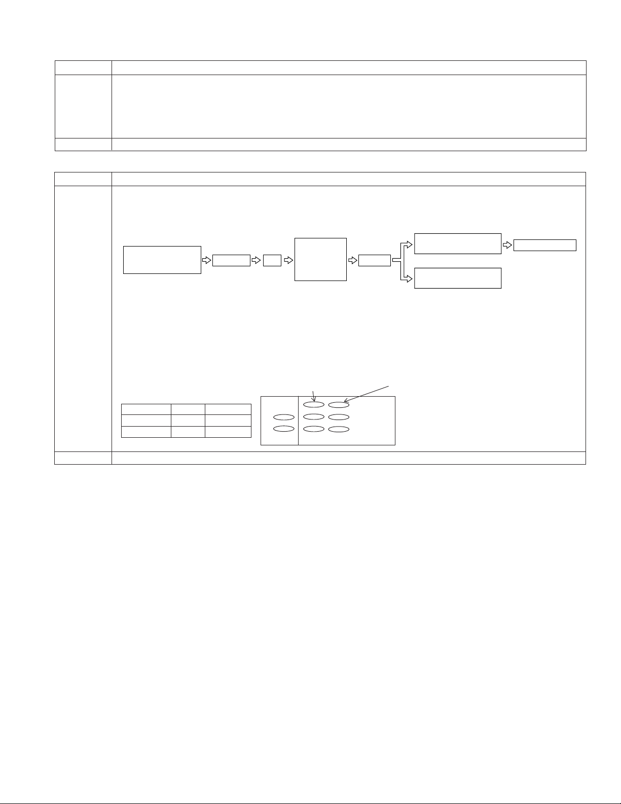
ADJUSTING THE ELECTROMAGNETIC CONVERSION CIRCUIT SYSTEM
12/9/2016
Published in Heiloo, Holland
1. PLL VCO adjustment
Mode VCR ADJ mode
Procedure 1) Playback the alignment tape (or a self-recorded tape).
2) Call the adjustment mode (V-ADJ).
3) Set the address "2A" and call the data.
4) Set the called data with the FF/REW key to the point where the playback screen appears.
(At this time, the screen full of block noise is OK.)
Examples • During E
2. Phase and equalizer adjustment → (Performed in the VCR mode)
Mode VCR ADJ mode
Procedure 1) Load a self-recorded tape into the deck.
2) After playback for 3 minutes, select the test mode 0F using the remote control for adjustment to start the
automatic adjustment. (The following sequence is automatically performed.)
2
PROM replacement. • During circuit board (Main) replacement.
VL-NZ10S/H/E
The built-in VI/O
colour bar is recorded.
VS REW
PB
Phase and
equalizer are
adjusted
automatically.
OK:
Blue LCD comes on.
Judgment
NG:
Red LCD comes on.
Tape is EJECT.
3) ON/OFF does a power source.
4) Error rate check
Select and fix the TEST MODE 0B on the adjustment remote control.
5) Manual adjustment method (video adjustment mode)
* Perform this adjustment with the self-recording/playback in the LP mode.
For phase, vary the data for the address 26 and 2B, and for equalizer, vary the data for the address 25 and 27,
to set the error rate is made as small as possible.
Error rate
Synchronization error 20 or less
Error rate 200 or less (SP Mode)
330 or less (LP Mode)
Phase Equalizer
H ch side 2B 27
L ch side 26 25
Synchronization error
H
L
Examples • During mechanism replacement. • During circuit board (Main) replacement. • During E2PROM replacement.
25
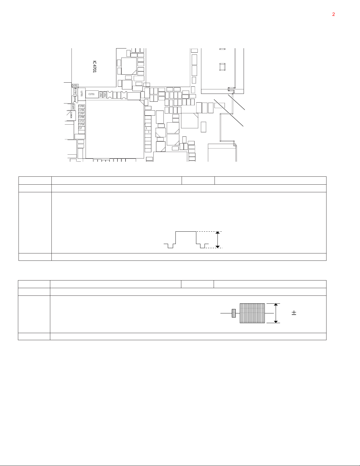
VL-NZ10S/H/E
0.62 0.05
,
,
,
,
y
y
y
y
7
1
R
7
9369089
3
12/9/2016
Published in Heiloo, Holland
ADJUSTING THE VIDEO I/O CIRCUIT SYSTEM
(Wiring board diagram: Main Side B)
C4701
Q3404
C3473
R3445
R1720
R1701
R3479
C1705
C1706
C1707
C1709
C1713
C1716
C1715
R1712
C1719
R1722
R1721
L1701
C1721
IC4701
C1711
C17C1
C1702
C1701
C1R
C4702
R1703
R1706
R1705
IC1701
R17C17R17R1
L1906
C1906
R1914
Q1906
R1702
R934
R1913
R935 R937
Q1905
C1703
C913
C911
C912
C909
R939
R938
C910
33
R940
R941
C915
C914
C924
R1704
R1707
C1704
R1708
R1709
C1710
C1712
R1710
R1711
C1714 R1911
C1717
C1718
C1720
R1991
R943
R968
R942
C916
R932
C1708
R1912
Q1920
D1900
IC900
R947 R953
R946
R948
R949
C918
R954
R965
FB1472
FB1471
Q1921
Q1900
R1900
C917
R969
C923
C919
R964
R952
R901
R958
R992
R957
R900
C900
R959
Q1201
R1980
R1986
R1985
R1968
R1983
C966
R966
C920
R960
C921
C922
R967
FB1475
TL1479
TL3341
TL3342
FB1473
R1480
TL3340
J1401
TL1477
R1478
R1476
TL3338
TL1475
SC
1. PCO D/A-Y adjustment
Test point TL1475 (connected to oscilloscope) Address VCR ADJ 22
Mode VCR STOP mode
Procedure 1) Connect the AVS cable and then connect it to the monitor (TO).
2) Call the adjustment mode (V-ADJ).
3) Set the address to "22", and call the date.
(100% white signal is output.)
4) Vary the data with the FF and REW keys to set the signal appearing at TL1475 to 1.0Vp-p ± 0.05Vp-p.
TL1475
PCO D/A-Y
TL1477
PCO D/A-C
1.0±0.05
Examples • During E2PROM replacement. • During IC4401 replacement. • During IC1401 replacement.
2. PCO D/A-C adjustment
Test point TL1477 Address VCR ADJ 23
Mode VCR STOP mode
Procedure 1) Connect the AVS cable and then connect it to the monitor (TO).
2) Call the adjustment mode (V-ADJ).
3) Set the address to "23", and call the data.
4) Vary the data with the FF and REW keys to set the signal
appearing at TL1477 to 0.62Vp-p ± 0.05Vp-p.
Examples • During E
2
PROM replacement. • During IC4401 replacement. • During IC1401 replacement.
,,,,
yyyy
,,,,
yyyy
,,,,
yyyy
,,,,
yyyy
26
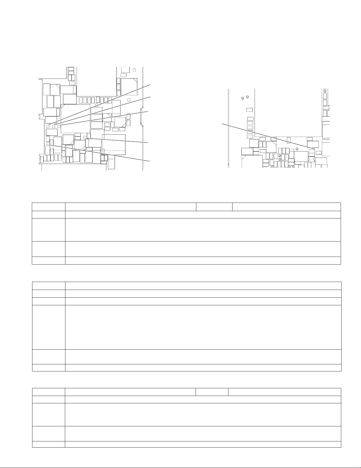
ADJUSTING THE LCD CIRCUIT
TL211
TL210
TL212
C218
C217
C220
R246
R219
C4465
R4468
C4464
Q4462
R4465
R4464
C4461
R4469
IC4461
FB
R7827
C4466
TL442
R7847
TL442
TL442
C7815
R7856
C7813
R4495
C7844
C4431
C4432
R4460
R7841
R4461
R7857
L7801
TL4429
C7842
C7837
R4403
C4463
R4462
C4462
TL4428
D7800
C7816
R4494
R7843
R7851
TL249
TL4421
Q4461
C4403
TL244
TL243
R4467
TL248
R4463
C213
C214
TL246
TL209
TL208
TL250
IC202
TL203
C208 C207
C210
FB204
C211
FB203
C203
C206
TL7800
R7852
TL4440
C7843
TL443
TL443
R7860
R4414
TL7800
VCO free-run
C
12/9/2016
Published in Heiloo, Holland
* To make this adjustment, set the backlight switch to the "NORMAL" position.
(Wiring board diagram: Main Side A)
VL-NZ10S/H/E
TL2803
C2829
L3701
TL2801
R2851
C2804
C2805
L2801
TL2802TL2804
C2803
R2811
R2813
C2800
R2815
R2853
R2852
Q3701
R2841
L2800
C2814
R2804
Q2802
R2825 R2824
R2844
C155
C3702
R3718
L151
R153
C165
IC2800
C2812
R2830
R2808
R152
R2829
R2822
Q2801
C2813
C156
TL2800
R2809
C2822
R156
R2820
C157
R2803
C2806
C2815
IC151
C154
C158
TL1269
C2810
C2811
C2809
L2802
C2816
C159
C2824
Q2800
R2814
R2812
R2802 R2801
C160
C2802
C161
R4473
P1203
D2801
R4478
C153
Q4471
C163
R154 C162
R159
R4477
TL151
P153
R4475 R4474
TL152
(Wiring board diagram: Main Side B)
TL2803(G OUT)
DAC full-scale
TL2802(R OUT)
DAC full-scale
TL2804(B OUT)
DAC full-scale
TL2800
COMMON PULSE
TL2801(C OUT)
COMMON PULSE
Adjustment procedure and connecting same as the VCR section.
1. VCO free-run adjustment
Test point TL7800 Address VCR ADJ 32
Mode VCR AV input
Procedure 1) Input the white 100% signal to AV input.
2) Connect the digital voltmeter to TL7800, and adjust DC voltage value to the specified adjustment value with
VCR ADJ 32.
Adjustment 2.00 ± 0.1V
rating
Examples • During E2PROM (IC705) replacement. • During VIO ENG (IC4401) replacement.
2. DAC full-scale adjustment
Test point TL2802(R OUT), TL2803(G OUT), TL2804(B OUT)
Address VCR ADJ 3D(R), VCR ADJ 3E(G), VCR ADJ 3F(B)
Mode VCR AV input
Procedure 1) Set the VCR ADJ 83/93/C0 to 00/77/00. (At this time, LCD can not be displayed.)
Adjustment 0.78V ± 10mV
rating
Examples • During E2PROM (IC705) replacement. • During VIO ENG (IC4401) replacement.
3. COMMON PULSE adjustment
Test point TL2801(C OUT) Address VCR ADJ 29(C)
Mode VCR AV input
Procedure 1) Connect TL2800 to GND.
Adjustment 6.95V ± 50mV
rating
Examples • During E
2) With the VCR ADJ 3D, adjust the output voltage of TL2802 and the DC voltage value of the digital voltmeter to
the specified adjustment values.
3) Similarly with the VCR ADJ 3E/3F, adjust the output voltage of TL2803/2804 and the DC voltage value of the
digital voltmeter to the specified adjustment values. (Same as Item (2))
4) Return the VCR ADJ 83/93/C0 to the initial value. (Initialization: C5/7F/28)
27
2) With VCR ADJ 29, adjust the output voltage of TL2801 and the DC voltage value of the digital voltmeter to the
specified adjustment values.
2
PROM (IC705) replacement.

VL-NZ10S/H/E
c
12/9/2016
Published in Heiloo, Holland
4. COM-BIAS adjustment
Test point LCD panel display surface Address VCR ADJ 33
Mode VCR AV input
Procedure 1) Input the white 100% signal to AV input.
2) Set up the illuminance meter (TOPCON IM-3) on the LCD panel surface. (The outside light must not enter.)
3) Minimize the ripple of the output waveform of the illuminance meter.
Adjustment Minimum
rating
Remark Make this adjustment after 5-minute or longer aging.
Examples • During LCD Panel replacement. • During IC705 replacement.
Response timeF0.6se
5. White Balance adjustment
Test point LCD panel display surface Address VCR ADJ 84, VCR ADJ 86
Mode VCR AV input
Procedure 1) Input the white 40% signal to AV input.
2) Input the white 40% signal to the standard monitor, and adjust it to become equal to that of the screen.
Adjustment Standard monitor
rating
Remark Make this adjustment after 5-minute or longer aging.
Examples • During LCD monitor replacement. LCD Panel • During IC4401, IC705 replacement.
28
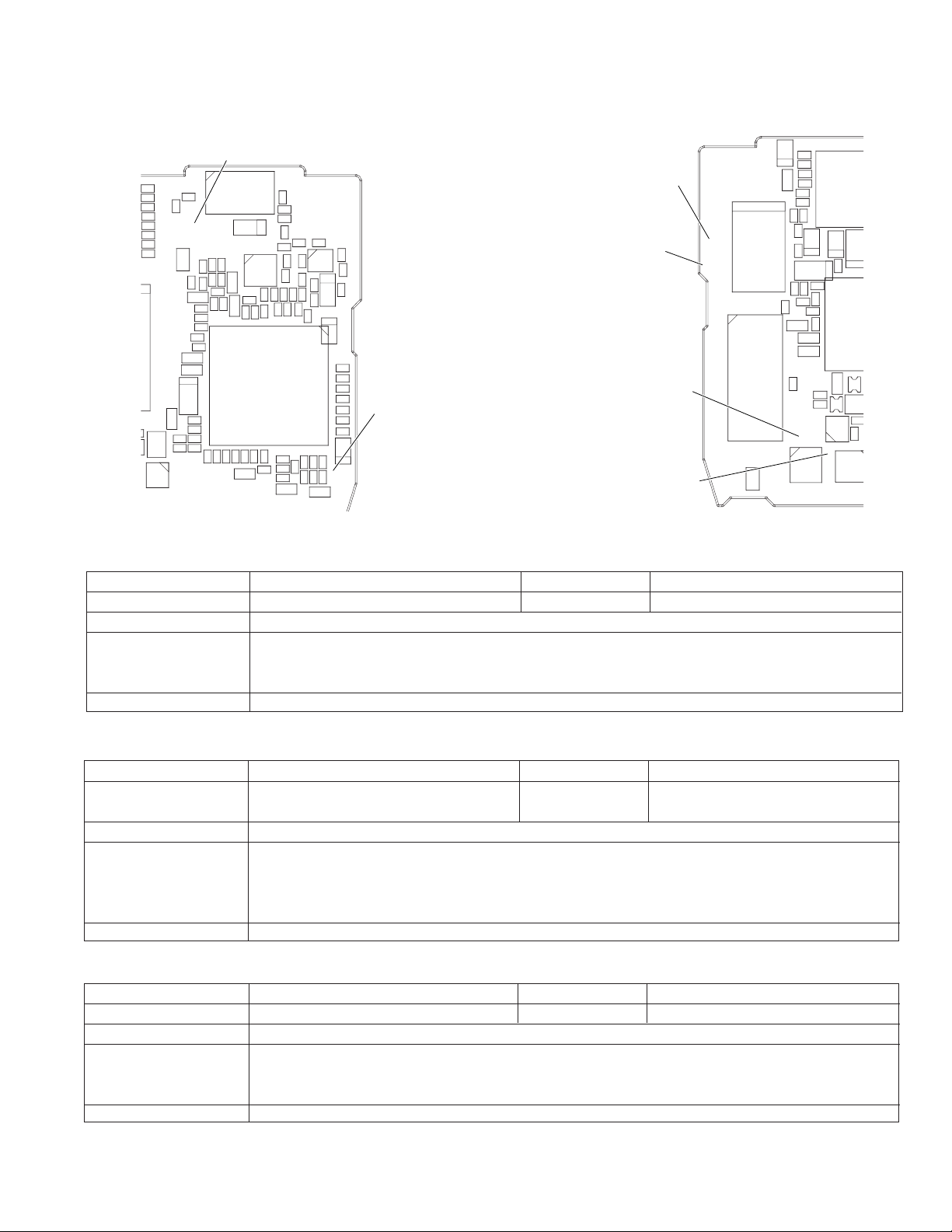
ADJUSTING THE MIC AMP CIRCUIT
TL6609
TL6601
TL6608
TL2663
TL2689
TL2687
TL2642
TL2655
TL2669
TL2667
TL2648
TL2647
TL2659
TL2643
TL2652
TL2654
TL2683
TL2645
TL2653
1
SC2604
SC6601
TL6602
C2608
R6689
R6690
TL2688
TL2662
R2607
C628
C2606
R635
TL605
R2616
R2617
TL2646
R2601C2607
C645
R2606
C2602
R2618
R2619
TL2644
C2605
R658
C617
C623
Q601
C629
C639
C2609
R654
R657
C624
R616
R613
TL604
C631
R614
Q606C606
R638
Q608
IC2601
Q605
R662
R641R655
C632
IC
TL6609(GND)
EE level check
Frequency character check
Super-directional microphone check
TL6608(TELE-MIC)
Super-directional microphone check
TL605
EE level check
Frequency character check
Super-directional microphone check
TL604
EE level check
Frequency character check
Super-directional microphone check
12/9/2016
Published in Heiloo, Holland
(Wiring board diagram: AIO Side A)
TL6607(INT MIC R)
EE level check
Frequency character check
R2627
C2611
TL2674
C2610
TL2673
0
C6645
C6644
R6651
R6650
R6647
R6649
TL2675
TL6607
R6685
C6635
C6639
C6640
C6641
C6646
R6652
C6643
C6681 R6682
C6648
R6637
R6684 C6680
C6634
C6620
SC2601
D6601
C6682 R6683
C6632
R6634
R6636
C6633
C6619
C6618
C6612
IC6603
R6635
R6633
IC6601
C6613
R6618
R6619
R6617 C6631 R6632
R2629
R2628
C6683
R6631
C6610
R6615
R6616
C6627
C6614
R2630
R2631
C6649
R6687
R6681
C6629
C6601
C6623
R6611
C6658
R6630 C6659 R6688
R6613 C6609
C6606
R6610
Q6601
TL6605
C6625 R6612
C6611
R6680 R6607
TL6606
C6603 C6608
D6602
R6686
R6602
C6628
C6630
R6666
R6665
R6629
C6622
TL6606(INT MIC L)
R6628
EE level check
C6621
Frequency character check
C6604 R6606
R2626
R2625
R2624
R2623
R2622
R2620
R2621
TL2679
TL2672
TL2671
TL2690
TL2686
TL2685
TL2684
TL2682
TL2681
TL2680
TL2678
TL2677
TL2676
L6601
Q6609
C6647
R6646
R6648
VL-NZ10S/H/E
(Wiring board diagram: AIO Side B)
1. EE level check
Measuring instrument Valve voltmeter Test point TL605, TL604
Mode P-ON (CAM), Zoom Mic "OFF" Adjustment rating -9dBs ± 3dB
Test signal 1kHz -54dBs sine wave
Procedure 1) Input 1kHz, -54dBs sine wave into TL6606(INT MIC L) and TL6607(INT MIC R).
Remark TL6609: GND
2. Frequency character check
Measuring instrument Valve voltmeter Test point TL605, TL604
Mode P-ON (CAM) Adjustment rating
Test signal 100Hz, 10kHz -54dBs sine wave
Procedure 1) Input 100Hz, -54dBs sine wave and then 10kHz, -54dBs sine wave into TL6606(INT MIC L) and
Remark TL6609: GND
3. Super-directional microphone check
Measuring instrument Valve voltmeter Test point TL605, TL604
Mode P-ON (CAM), Zoom MIC "TELE" Adjustment rating -14dBs ± 3dB
Test signal 1kHz -54dBs sine wave
Procedure 1) Input 1kHz, -54dBs sine wave into TL6608(TELE-MIC).
Remark TL6609: GND
2) Make sure that the signal level of TL605 Audio-L out and TL604 Audio-R out is within the standard
limits.
(1kHz standard)
100Hz: -11dBs ± 3dB
Parameter; Zoom Mic "OFF" 10kHz: 0dBs ± 3dB
TL6607(INT MIC R).
2) At this time make sure that the signal level of TL605 Audio-L out and TL604 Audio-R out is within the
standard limits (1kHz standard).
2) Make sure that the signal level of TL605 Audio-L out and TL604 Audio-R out is within the
standard limits.
29
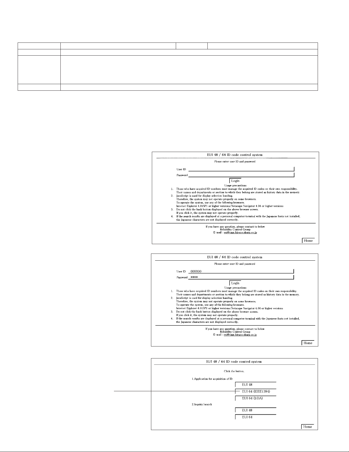
VL-NZ10S/H/E
12/9/2016
Published in Heiloo, Holland
DV INTERFACE (IEEE1394) ID SETTING
This unit has a DV interface function conforming to IEEE1394. Therefore, each individual ID number must be used for each unit. Since this
ID is written on the E
Address 180, 17F, 17E Mode VCR
Adjustment rating ID number obtained from the URL below
Procedure 1) Refer to the ID code application below.
Examples • During E
■ ID code is acquired
1. Connect with the EUI48/64 ID code control system.
(1) Start the Internet Explorer or Netscape Navigator.
(2) Access the following address.
(URL:http://www.rcg.kami.sharp.co.jp/quics/e_index.html)
Select the "EUI48/64 ID code control system" from the "Service" item.
Note: If you want to establish a connection by directly inputting the URL, please input the following.
2
PROM (IC302) on the head amp PWB, the ID must be newly written when replacing this IC or the head amp PWB.
2) Set the data acquired in step 1) to the corresponding address in the VCR adjustment mode.
* Download an ID number or write it on the main unit according to the notice from the AV Systems Group
"Issue No. S8-001".
2
PROM (IC302: on the H/A unit) replacement. • During the H/A unit (RAMP-0035TAN4) replacement.
URL:http://www1.rcg.kami.sharp.co.jp:7000/adrs_agt/adrs_dba/ide00010.main
The login screen will appear.
(3) For the [User ID], input the [Password].
Click on [Login].
(4) Click on [EUI 64 (IEEE 1394)] from the
[1. Application for acquisition of ID].
Click
30
 Loading...