

Sharp VL-H870S, VL-H96E, VL-H960E, VL-H860S, VL-H860H Service Manual
...
VL-H870U
VL-H860S/H/VL-H870S
VL-H875U
VL-H890S/VL-H94E
VL-H890U
VL-H96E/VL-H960E
VL-H860S/H/VL-H870S
VL-H860S/H/VL-H870S
VL-H890S/VL-H94E
VL-H890S/VL-H94E
VL-H96E/VL-H960E
VL-H96E/VL-H960E
SERVICE MANUAL
SERVICE MANUAL
LIQUID CRYSTAL CAMCORDER Hi
VL-H860S/H/H94E
S69I1VL-H860S
LIQUID CRYSTAL CAMCORDER Hi 8 PA L
VL-H860S/H
VL-H870S
VL-H890S
VL-H94E
VL-H96E
MODELS
In the interests of user-safety (Required by safety regulations in some countries) the set should be restored to its
original condition and only parts identical to those specified
be used.
VL-H960E
8
PAL
VL-H870S/H890S/H96E/H960E
MODELS VL-H860S/H/H870S/H890S/H94E/H96E/H960E
CONTENTS
1. SPECIFICATIONS ........................................................................................................................... 1-1
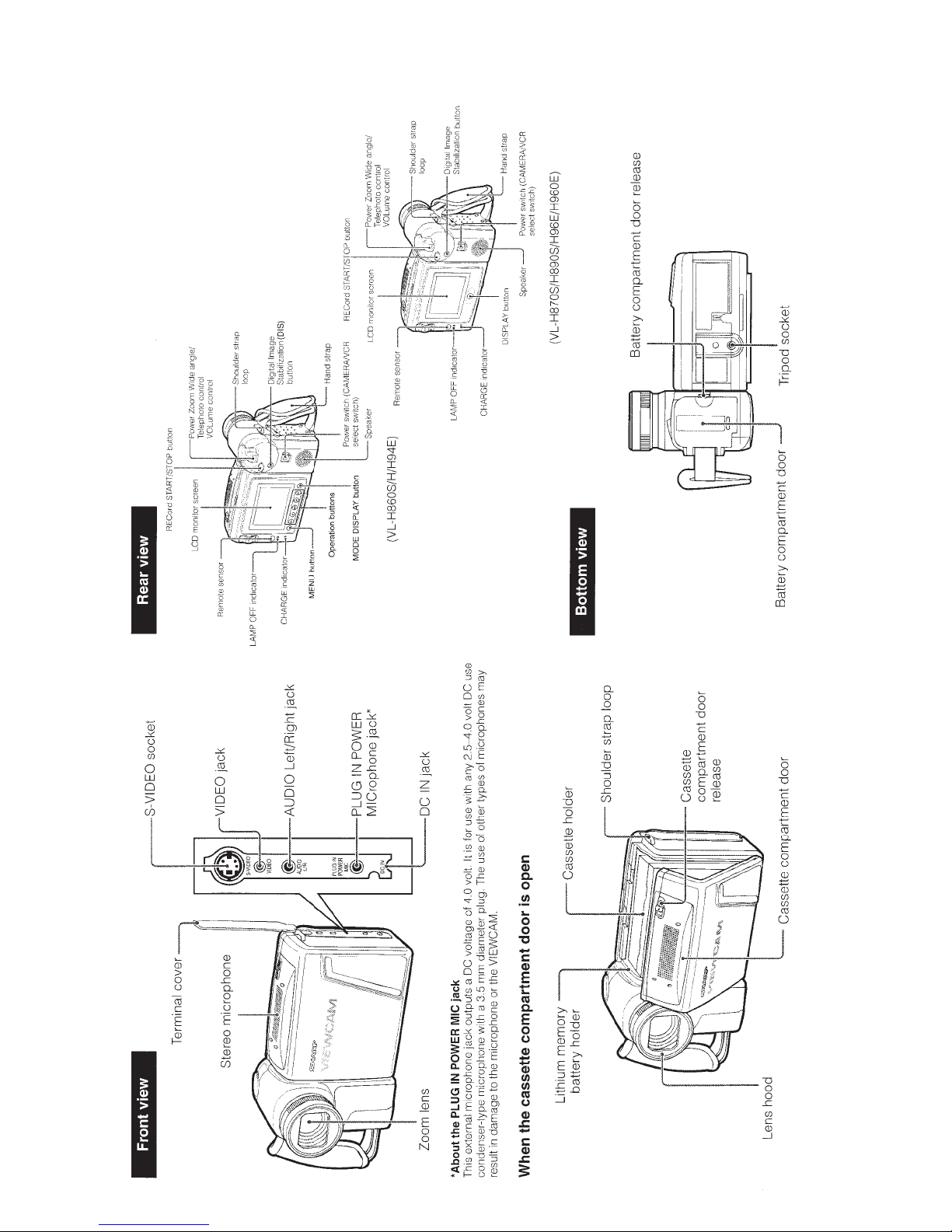
2. PART NAMES AND FUNCTION ......................................................................................................2-1
3. DISASSEMBLY OF THE SET..........................................................................................................3-1
4. MECHANISM ADJUSTMENT ..........................................................................................................4-1
5. ADJUSTMENT OF VCR AND CAMERA..........................................................................................5-1
6. SYSTEM BLOCK DIAGRAMS ........................................................................................................ 6-1
7. SCHEMATIC DIAGRAMS ............................................................................................................... 7-1
8. SEMICONDUCTOR LEAD IDENTIFICATION ................................................................................ 8-1
9. PRINTED WIRING BOARD ASSEMBLIES..................................................................................... 9-1
10.REPLACEMENT PARTS LIST ...................................................................................................... 10-1
11.PACKING OF THE SET ................................................................................................................ 11-1
Page
SHARP CORPORATION

VL-H860S/H/VL-H870S
VL-H890S/VL-H94E
VL-H96E/VL-H960E
1. SPECIFICATIONS
Signal System: PAL standard
Recording System: 2 rotary heads, helical scanning system
Cassette: 8 mm video tape, MP type or Hi8 MP, ME type
Recording/Playback Time: 90 minutes (P5-90)
Tape Speed: 20.051 mm/second
Pickup Device: 1/4" (6.4mm, effective size: 4.5 mm) CCD image sensor (with approx.
470,000 pixels including optical black)
Lens: 22 × power zoom lens (F1.6, f=4.0-88.0 mm) and full-range auto focus
Lens Filter Diameter: 46 mm
Monitor: 3" (7.5 cm) (VL-H860S/H/H870S/H94E/H96E)
3.5" (8.8 cm) (VL-H890S/H960E)
full-color LCD screen (TFT active matrix)
Microphone: Electret stereo microphone
Color Temperature Compensation: Auto white balance with white balance lock
Minimum Illumination: 5 lux* (with gain-up, F1.6)
Video Output Level: 1.0 Vp-p 75-ohm unbalanced
Audio Output Level: –8 dBs, impedance less than 2.2 kohms
Speaker Output: 200 mW
External Microphone Input: 3.5 mm diameter mini-plug, –66 dBs, output impedance 6.8kohms, DC
4 V, for plug-in-power microphone use
Power Requirement: DC 7.4V
Power Consumption:
Operating Temperature: 0°C to + 40°C
Operating Humidity: 30% to 80%
Storage Temperature: –20°C to +60°C
Dimensions (approx.): 180 mm (W) × 112 mm (H) × 107 mm (D)
Weight (approx.): 740g (VL-H860S/H/H94E)
4.95W (VL-H860S/H/H870S/H94E/H96E)
5.3W (VL-H890S/H960E)
(during camera recording in full auto mode with zoom motor off, Extend
Zoom, DIS and Snapshot functions off, and backlight in normal mode)
760g (VL-H870S/H96E)
765g (VL-H890S/H960E)
(without battery pack, lithium battery, video cassette, and lens cap)
VL-H860S/H/VL-H870S
VL-H890S/VL-H94E
VL-H96E/VL-H960E
VL-H870U
VL-H875U
VL-H890U
AC Adapter UADP-0304TAZZ
Power Requirement: AC 110-240 V, 50/60 Hz
DC Output: 9.0 V
Power Consumption: 15 W
Dimensions (approx.): 68 mm (W) × 37 mm (H) ×
130 mm (D)
Weight (approx.): 230 g
Specifications are subject to change without notice.
* Minimum illumination: Since there is no widely accepted testing procedure for determining minimum
illumination capability, lux ratings are comparable only between models from the
same manufacturer
Battery Pack BT-L241
DC Output: 7.4 V
Dimensions (approx.): 40 mm (W) × 43 mm (H) ×
54 mm (D)
Weight (approx.): 97 g
1-1
VL-H870U
VL-H860S/H/VL-H870S
VL-H875U
VL-H890S/VL-H94E
VL-H890U
VL-H96E/VL-H960E
2. PART NAMES AND FUNCTION
For details on the use of each control.
VL-H860S/H/VL-H870S
VL-H890S/VL-H94E
VL-H96E/VL-H960E
2-1
VL-H860S/H/VL-H870S
VL-H890S/VL-H94E
VL-H96E/VL-H960E
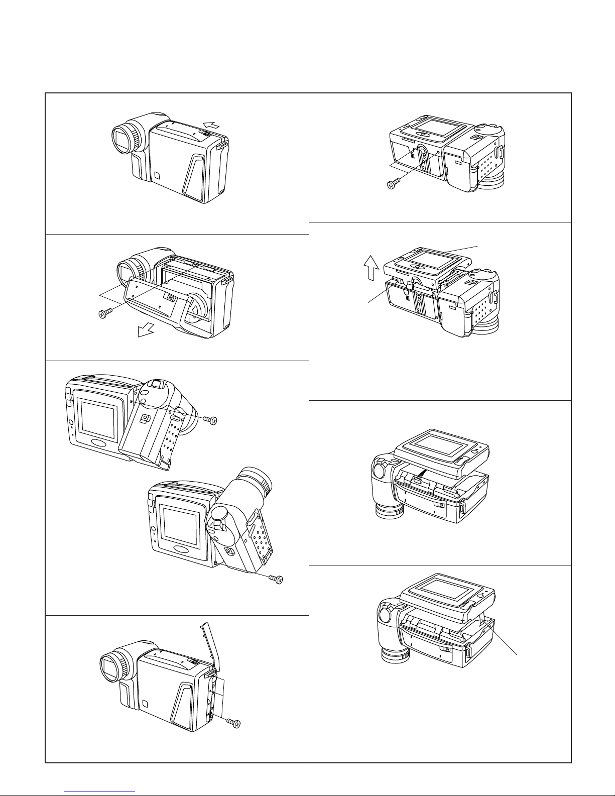
3. DISASSEMBLY OF THE SET
3-1. DISASSEMBLY OF THE VCR PARTS
Note:
Before removing the cabinet, turn off the power supply, and ascertain that the battery has been removed.
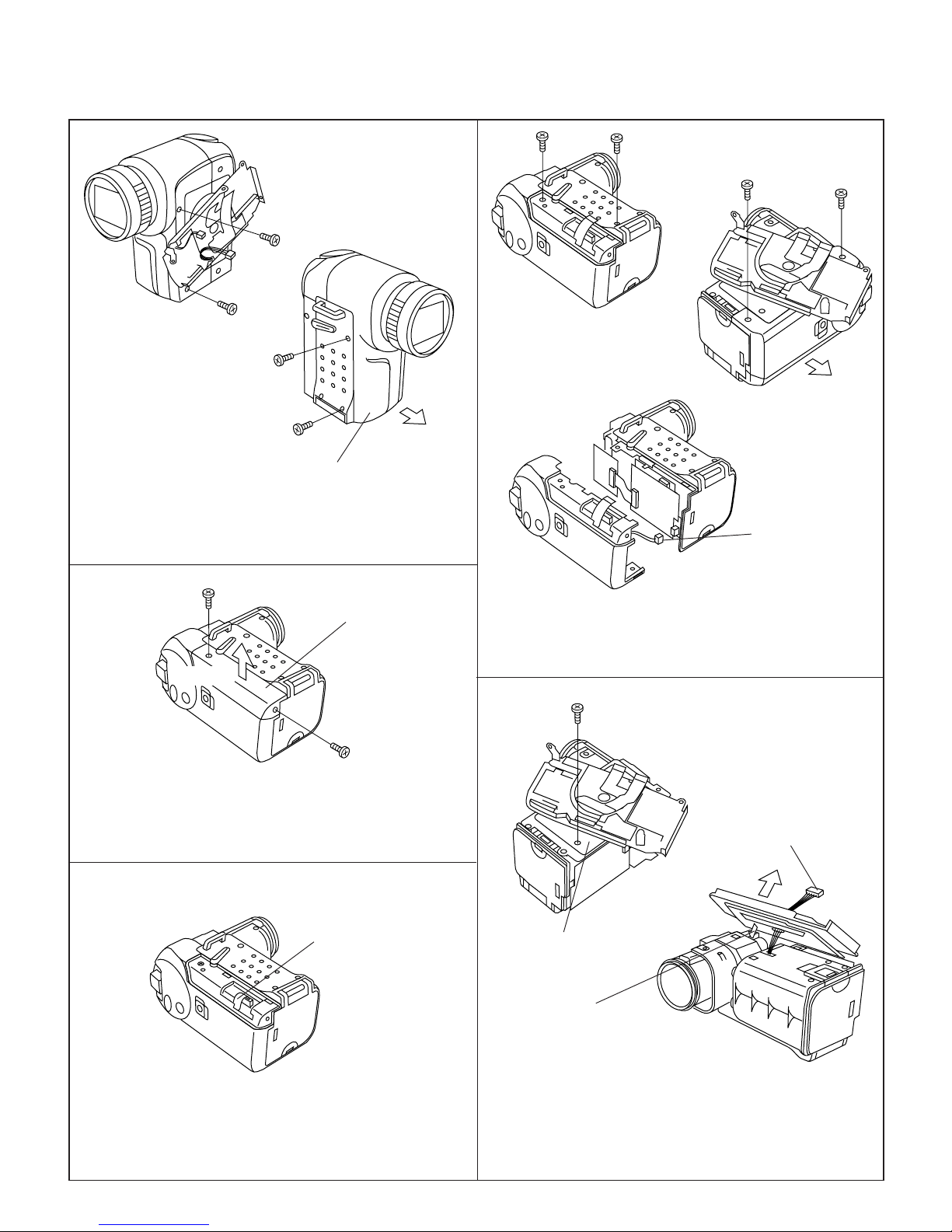
<1. Removal of the Cabinet L>
(i)
VL-H860S/H/VL-H870S
VL-H890S/VL-H94E
VL-H96E/VL-H960E
VL-H870U
VL-H875U
VL-H890U
(1) Slide the VCR lid knob in the arrow direction, open the VCR
lid.
(b)
(2) Remove the screws (b)LX-HZ0018TAFF(2pcs.).
(i)
(5) Remove the screws (i)XiPSN20P04000(2pcs.).
L.Cabinet
FPC connector
(6) Close the VCR lid.
(7) Lift about half of the L.Cabinet parts in the arrow direction,
remove the FPC connector.
(3) Turn the Camera section, and remove the screws
(i)XiPSN20P04000(1pc.), (d)XiPSF20P04000(1pc.).
(4) Remove the A.V.terminal cover and the screws
(i)XiPSN20P04000(3pcs.).
(8) Remove the outside charging battery connector.
(d)
A.V.terminal FPC
(9) Remove the A.V.terminal FPC.
Note:
The FPCs and the wires of process (7), (8), and (9) are connect-
(i)
ing with the L.Cabinet, and remove the L.Cabinet while it is
floating from the main body.
If the L.Cabinet is drawed violently, they have some apprehensions of snap off the wires.
3-1
VL-H870U
VL-H860S/H/VL-H870S
VL-H875U
VL-H890S/VL-H94E
VL-H890U
VL-H96E/VL-H960E
VL-H860S/H/VL-H870S
VL-H890S/VL-H94E
VL-H96E/VL-H960E
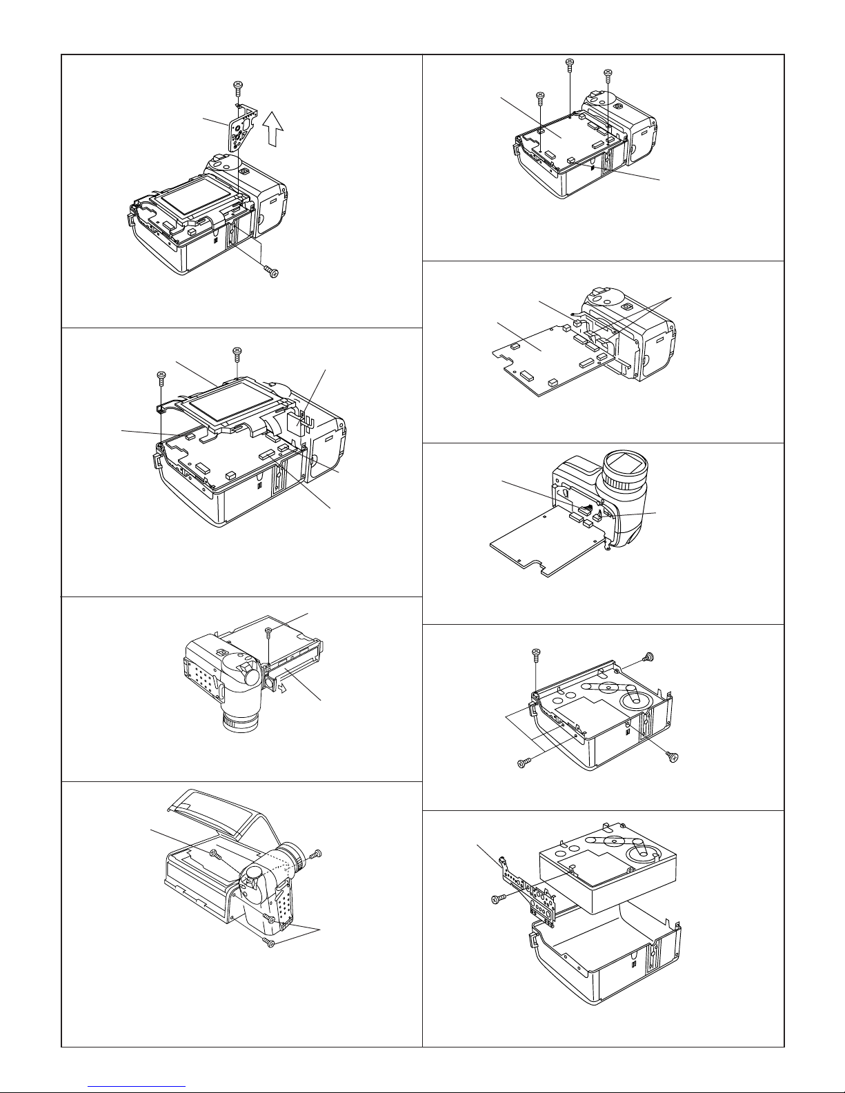
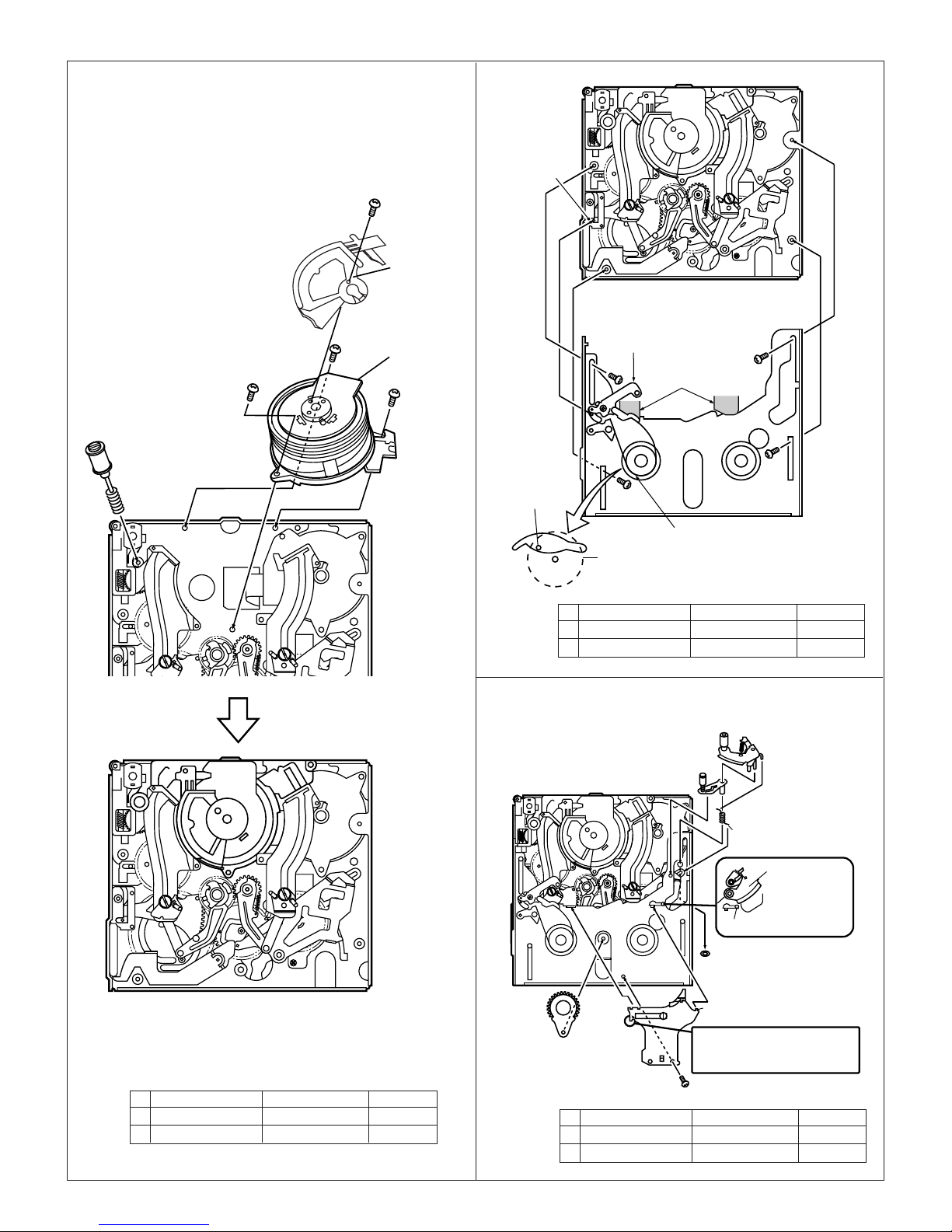
<2. Remove the Tripod Angle.>
(d)
Tripod Angle
(d)
(1) Remove the screws (d)XiPSF20P04000(3pcs.), pull the Tri-
pod Angle.
<3. Removal of the LCD unit>
LCD unit
(d)
C
(b)
Inverter transformer
Main PWB
(f)
(f)
(f)
Microphone connector
(3) Remove the Microphone connector.
Remove the main PWB fixing screws (f)XiPSD20P03000(3pcs.).
Lift the main PWB in the arrow direction and remove the
connection "B to B".
<5. Removal of the main P.W.B>
Lithium connector
Main PWB
Camera FPC
(1) Remove the Camera FPCs(2pcs.) are connected with main
PWB and the Camera section, and remove the Lithium
connector.
B
A
(1) Remove the FPCs from connectors A, B and C.
("C" isn't used with VL-H860S/H94E/EX.)
(2) Remove the screws (d)XiPSF20P04000(1pc.) and (b)LX-
HZ0018TAFF(1pc.).
<4. Removal of the V.Cabinet>
Remove the Lithium
Holder
(b)
V.Cabinet
(1) • Firstly, remove the Lithium Holder.
•Turn to upside the surface of V.lid, remove the
V.Cabinet fixing screw (b)LX-HZ0018TAFF(1pc.).
(d)
(b)
Remove the battery
connector
Remove EJECT TURN
S.W. connector
(2) The same as process 4., remove the battery connector in the
reverse side of PWB and EJECT TURN S.W. connector, and
disconnect the Tilt section and main PWB.
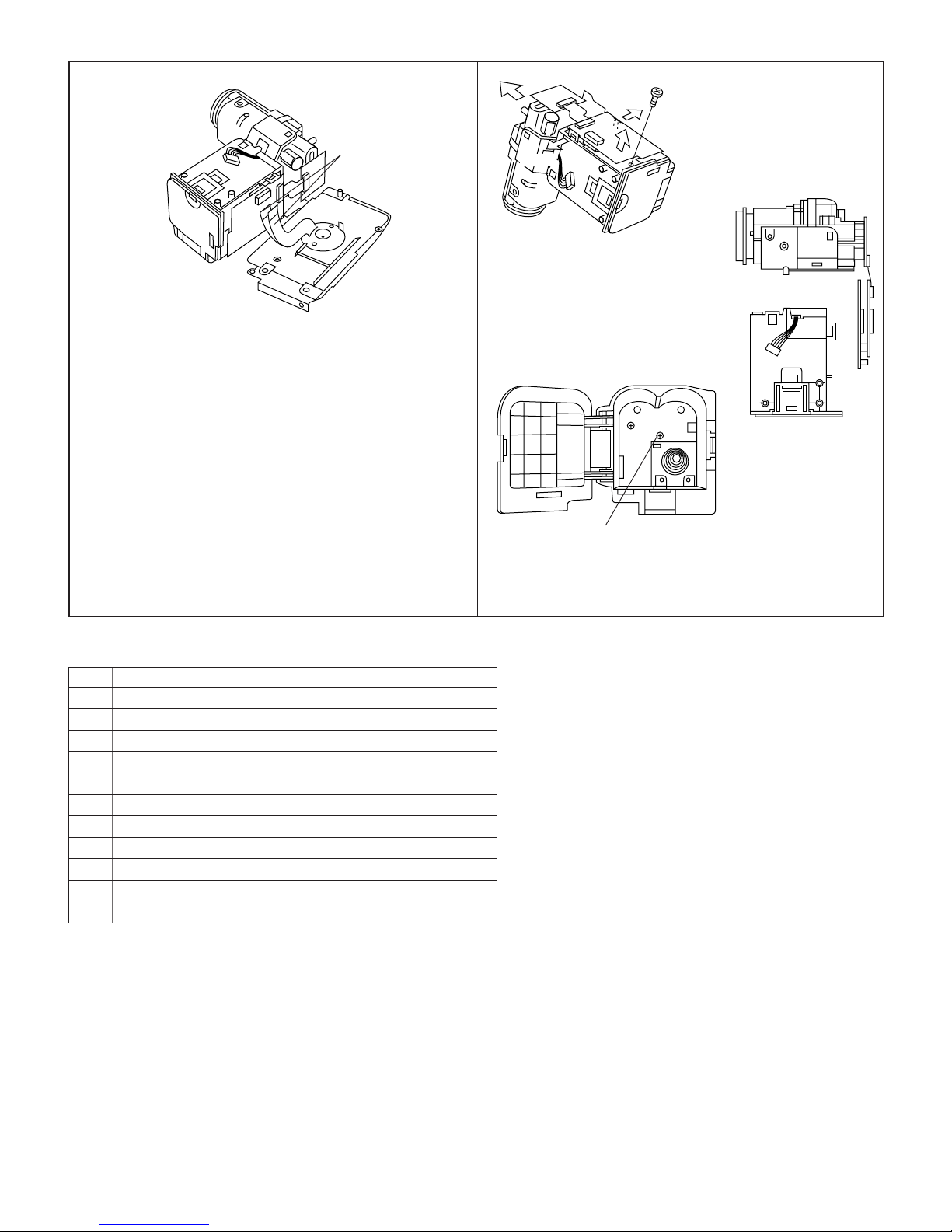
<6. Removal of the Cabinet and Mechanism>
(b)
(d)
(e)
(e)
(1) Remove the screws (b)LX-HZ0018TAFF(1pc.), (d)
XiPSF20P04000(3pcs.) and (e)LX-BZ0191TAFD(2pcs.).
Side angle
(2) Turn the Camera section to right angle, remove the Tilt side
fixing screws (g)LX-HZ0045TAFF(2pcs.), the bottom side
screw (b)LX-HZ0018TAFF(1pc.), open the VCR lid, and
remove the slant wise screw (d)XiPSF20P04000(1pc.).
Note:
The Tilt section is setting with the parts of the Camera section .
(Never remove the parts of Camera section only.)
(e)
(g)
(2) Pull the Mechanism from K.S.V.Cabinet, remove the screw
(e)LX-BZ0191TAFD(1pc.) and the side angle.
3-2
VL-H860S/H/VL-H870S
VL-H890S/VL-H94E
VL-H96E/VL-H960E
<7. Removal of the cassette compartment lid>
B
C
C
E
B
VL-H860S/H/VL-H870S
VL-H890S/VL-H94E
VL-H96E/VL-H960E
VL-H870U
VL-H875U
VL-H890U
Note:
When fixing the cassette compartment lid, first engage the
A
claws A and B, and then engage the claws C and D, verify that
the four claws (A, B, C and D) of the cassette compartment lid
are securely engaged as shown in the view below.
D
Claw C
A
D
F
Claw B
Claw D
View E
Claw A
View F
(1) Using the slotted precision screwdriver, push and turn the two claws (C and D) which fasten the cassette compartment lid, and
the cassette compartment lid will be removed from the hook area of the cassette component.
(2) Turning the cassette compartment lid in the arrow direction, lift it, and the claws A and B will be disengaged to remove the
cassette compartment lid.
Note:
Take care to prevent breaking the claws of the cassette compartment lid.
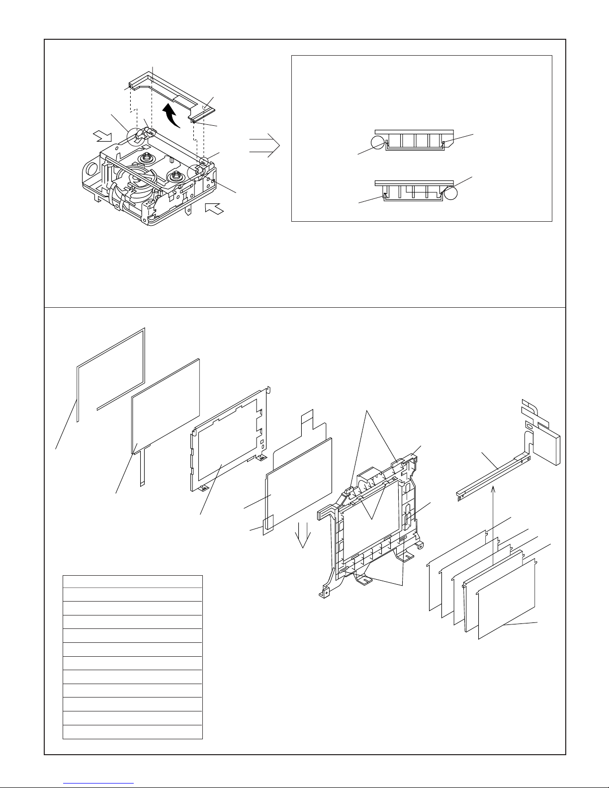
<8. Removal of LCD Unit>
(3)
(L)
(B)
(A) Touch Panel Fitting A
(B) Touch Panel
(C)LCD Panel
(D)LCD Holder A
(E) DBEF Sheet
(F) Prism Sheet
(G)Diffusion Sheet
(H)Light Guide Plate
(I) Reflection Polarizing Sheet
(J) Lamp Inverter
(K) LCD Holding Sheet
(L) Touch Panel Sheet
(A)
(C)
(K)
(D)
(2)
(4)
(a)
(1)
(J)
•At the time of removing from the LCD Holder A(D), and take off the hooks(1)(2pcs.).
•At the time of removing from the LCD Holder A(D), take off (K), remove the FPC from
the hooks(3)(2pcs.), disengage the claw(2), and slide the LCD Panel(C) in the (a)
direction to remove the LCD Holder A(D).
•At the time of removing from the LCD Holder A(D), remove the claws(4)(2pcs.).
•As for VL-H860S/H/H94E (A) (B) (L) (E) isn't used.
``
` Refer to the item CABINET EXPLODED VIEW about other parts.
``
(E)
(F)
(G)
(H)
(I)
3-3
VL-H870U
VL-H860S/H/VL-H870S
VL-H875U
VL-H890S/VL-H94E
VL-H890U
VL-H96E/VL-H960E
3-2. REMOVAL OF THE CAMERA PARTS
Note:
Before removing the Cabinet, turn off the power supply,and ascertain that the battery has been removed.
VL-H860S/H/VL-H870S
VL-H890S/VL-H94E
VL-H96E/VL-H960E
(a)
(c)
(b)
(d)
Pull out
Camera front cabinet
1. Remove the screws (b)LX-HZ0018TAFF(1pc.), (a)LX-HZ
0018TAFN(1pc.),(c)LX-HZ0045TAFN(1pc.)and
(d)XiPSF20P04000(1pc.), pull out the Front cabinet.
(b)
(d)
(c)
Speaker connector
(c)
Pull out
(g)
Camera rear grip cover
Remove
(g)
2. Remove the screws (g)LX-HZ0045TAFF(2pcs.) and the Camera rear grip cover .
Connector
4. Remove the screws(b)LX-HZ0018TAFF(1pc.),(c)LXHZ0045TAFN(2pcs.) and (d)XiPSF20P04000(1pc.),pulling out
the Camera rear Cabinet, and remove the Speaker connector.
(c)
Battery catcher connector
Pull out
Tilt Frame C
Claw
3. Remove the connector.
5. Remove the screw (c)LX-HZ0045TAFN(1pc.) and pull out
the Tilt Frame C.
Pull out the Tilt Frame C. at right angle, because of closing the
claw.
Then, pull out the battery catcher connector from the Tilt
Frame C.
3-4
VL-H860S/H/VL-H870S
VL-H890S/VL-H94E
VL-H96E/VL-H960E
Tilt connector
6. Remove the Tilt connectors(2pcs.) as the Tilt Frame C. are
floating in the air.
Note:
Take care to prevent breaking the FPC when the Tilt Frame C.
is removing from them.
Remove
Open
Open
(c)
Remove
VL-H860S/H/VL-H870S
VL-H890S/VL-H94E
VL-H96E/VL-H960E
VL-H870U
VL-H875U
VL-H890U
Screws
a LX-HZ0018TAFN M2x6 Tapping Screw, Silver
b LX-HZ0018TAFF M2x6 Tapping Screw, Black
c LX-HZ0045TAFN M2x4 Tapping Screw, Silver
d XiPSF20P04000 M2x4 Small Screw, Black Zinc Plating
e LX-BZ0191TAFD M2 Special Screw
f XiPSD20P03000 M2x3 Screw
g LX-HZ0045TAFF M2x4 Tapping Screw, Black
h LX-HZ0013TAFF M1.7x6 Tapping Screw, Black
i XiPSN20P04000 M2x4 Small Screw, Silver
j LX-HZ0050TAFN M1.7x4 Tapping Screw, Silver
k LX-BZ0236TAFD M2x8 Screw
l XiPSF20P03000 M2x3 Screw, Black
(g)
7. Remove the screws (g)LX-HZ0045TAFF(1pc.) and (c)LXHZ0045TAFN(1pc.), opening the claws(2pcs.) to outward,
remove the Lens unit with Camera P.W.B.
3-5
VL-H870U
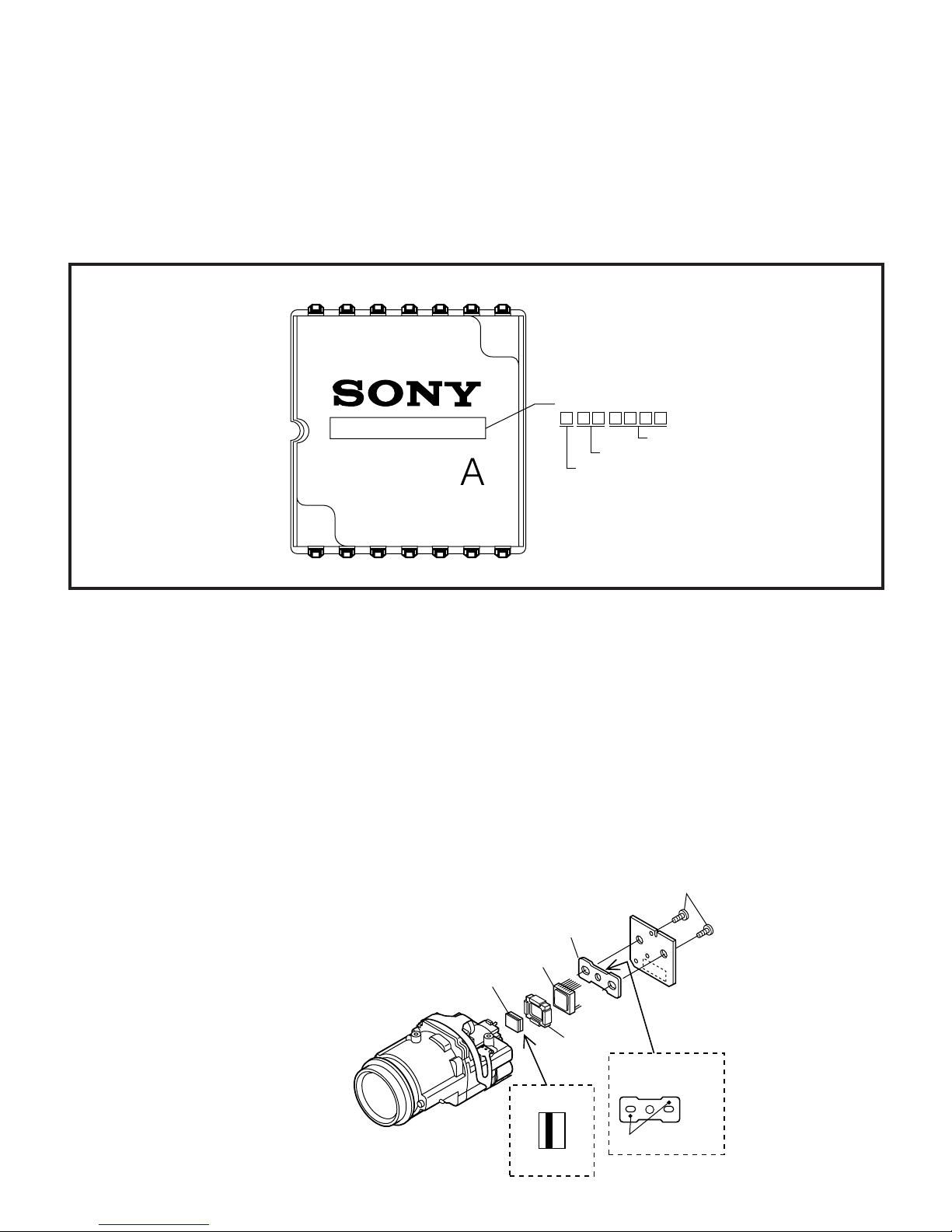
Mark
The THIN SIDE
faces the lens
Sensor Holder
CCD Sensor
Crystal
Rubber
(b)
Lens
Side
CCD
Side
The mark must be on
this face.
I C X 2 0 9
A K
17
14 8
Lot No. (Max 7)
Control No.
Week manufactured
Year manufactured
VL-H860S/H/VL-H870S
VL-H875U
VL-H890S/VL-H94E
VL-H890U
VL-H96E/VL-H960E
VL-H860S/H/VL-H870S
VL-H890S/VL-H94E
VL-H96E/VL-H960E
3-3. REPLACEMENT OF CCD SENSOR
3-3-1. Before replacement
1) The CCD image sensor is more sensitive to electrostatic breakage than C-MOS LSI. Therefore sufficient means to prevent
electrostatic damage must be taken when it is replaced.
• Ground the soldering iron.
• Ground also the human body, using the wrist strap(through an 1 Mohm resistor).
• Until the CCDsensor is mounted on the PWB, fit it to the conductive sponge, and short-circuit the foot lead.
2) Take utmost care so that the surface glass of CCD sensor and optical filter are not contaminated and damaged. If any contamination
is found, for example fingerprint, wipe it off with silicon paper or clean chamois skin.
3) When replacing the CCD sensor, use the antistaic grounded soldring iron, and perform quickly soldering.
3-3-2. Removal of CCD
1) Unsolder the CCD sensor leads from the sensor PWB.
2) Take out the sensor PWB.
3) Remove the two screws (b), and remove the sensor holder and CCD sensor.
3-3-3. Mounting of CCD
1) Place the lens unit upright (since the CCD sensor mount ID faces upward, care must be taken so as not to damage the front lens of
unit), put the crystal filter first and then the dust protection rubber into the CCD holder of lens unit. Set the crystal unit with its thin side
toward the lens unit.
2) Place the CCD sensor so that the its No. 1 pin is at the right lower (Positioning hole to be at right), and put the CCD sensor into the
CCD holder. For smooth and tight fitting, press the right lower part of back of CCD sensor, and then press the left upper part.
Note: Pay attention to the direction of CCD sensor.
3) Place the sensor holder so that its two round markings be visible, and fix the sensor holder with the two screws ((b)LX-HZ0013TAFF).
4) Mount the sensor PWB so that the CCD sensor leads go thorough the PWB holes.
5) Solder the CCD sensor lead to the sensor PWB.
Note: Take care not to apply excessive heat.
3-6
VL-H870U
VL-H860S/H/VL-H870S
VL-H875U
VL-H890S/VL-H94E
VL-H890U
VL-H96E/VL-H960E
4. MECHANISM ADJUSTMENT
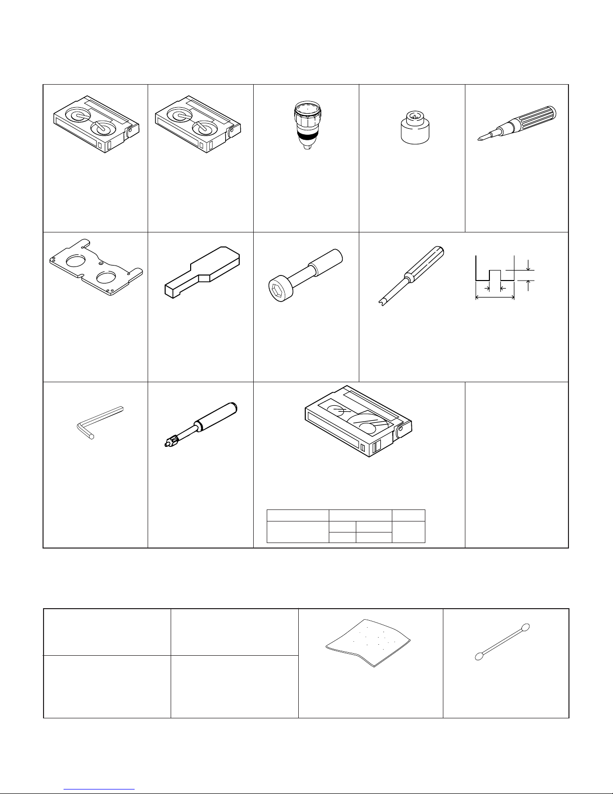
4-1. MECHANISM CHECKING/ADJUSTING JIGS, TOOLS AND PARTS
4-1-1. Mechanism checking/adjusting jigs and tools
<Note: The entries of list>
VL-H860S/H/VL-H870S
VL-H890S/VL-H94E
VL-H96E/VL-H960E
Configuration
1. Name
2. Part No.
3. Code
* Model, Uses Remarks
1. Cassette torquemeter
for PB
2. JiG8T-012
3. CV
* (10 g·cm/25 g·cm)
1. Master plane
2. JiGMP-MX7U
3. CG
* For adjustment of Tu guide
height, Si roller height and
checking of reel disk height
1. Hex wrench
3. —
*
For loosening or tight-
ening of Motor stator
(1.3mm)
1. Cassette torquemeter
for VS-REW
2. JiG8T-032
3. CV
* (50 g·cm/25 g·cm)
1. Height adjusting jig
2. 9DAGH-E31S
3. BM
* For adjustment of Tu
guide height and Si
roller height
1. Tension Band and Plate
Adjusting Jig
2. JiGDRiVERMX7U2
3. BN
1. Torque gauge
2. JiGTG0045
3. CN
* For measurement of
loading brake torque
1. Tu guide height
adjusting driver
2. 9EQDRiVER-V712
3. BL
1. Torque gauge head
2. JiGTH-MX7U
3. BS
* For torque gauge listed
left
1. Guide roller height adjusting driver
2. JiGDRiVERHMX7U
3. BU
* Bit shape (See the figure above.)
1. Alignment tape
2. VR2DBOPS
3. BT
TAPE CONTENTS
VIDEO IMAGE AUDIO TIME
MONOSCOPE L-CH 400Hz 30MIN
R-CH 1,000Hz
1. Torque driver
(1.5 kg·cm)
2. JiGTD1500RT0H
3. CB
Tolerance±0.1
2
1.8
Edge
4
thickness 0.5
<Others>
(1) Slide calipers
(2) High-precision screw-
drivers (Phillips head,
slotted head)
(3) Radio pliers (with thin
jaws)
(4) A pair of tweezers
4-1-2. Parts for periodic inspection and maintenance.
1. Oil
COSMOHYDRO HV100
* Cosmo Oil Co., Ltd.
1. Greases
Morycoat YM-103/X5-6020
* Dow Coaning
1. Screw locking agent
(1401B)
* Three Bond
1. Cleaning liquid
(Industrial-use ethyl alcohol)
<Note: The entries of list>
1. Cleaning paper
2. JiGDUSPER
3. AP
* Dusper ∑ (Sigma) (Ozu Co., Ltd.)
4-1
Configuration
1. Name
2. Part No.
3. Code
* Model, Uses Remarks
1. Superfine swab
* Commercially available
item

VL-H860S/H/VL-H870S
VL-H890S/VL-H94E
VL-H96E/VL-H960E
VL-H860S/H/VL-H870S
VL-H890S/VL-H94E
VL-H96E/VL-H960E
4-2. ITEMS AND TIMINGS OF INSPECTION AND MAINTENANCE
The mechanism of VCR needs the following periodic inspection and maintenance in order that it maintains its high quality. Also,
after the machine is repaired, execute the following maintenance and checks regardless of how long it has been used.
4-2-1. Inspection and maintenance list
Checking/Maintenance point
Tape travel system
Tape travelling route
(Refer to Section)
Drum (Refer to Section)
Video head
Timing belt
Pinch roller
Capstan D.D. motor
Driving system
Relay Pulle shaft
Pulle gear shaft
Drive gear shaft
Loading motor
Performance check
Abnormal sound
PB/VS-REW take-up torque
PB/VS-REW back tension torque
Tu brake
HC (Head Cleaner)
500 1,000 1,500 2,000 3,000
★★★★★
Oil: COSMOHYDRO HV100
Greases: MORYCOAT YM-103/X5-6020
Screw locking agent: THREE BOND 1401B
Cleaning liquid: Industrial-use ethyl alcohol
Usage time (hrs.)
★★★
∆∆∆
∆∆∆
★★★
★★★
★★★
★★★
: Replace.
: Clean.
∆ : Apply oil.
★ : Check.
Possible symptom
encountered
• Lateral noise
• Unclean head
• Screen shaking
• Improper S/N ratio
• No color appears.
• Tape does not run.
• Tape slackens.
• Screen shakes.
• Abnormal sound • Apply oil.
• Not ejectable
• The specific mode cannot
be set.
Remarks
Rollers
• If abnormal rotation or deflection (significant) is
found, replace the roller.
Other than rollers
• Clean the tape contacting
areas. Be sure to use the
specified cleaning agent.
• Replace if failure is found.
(Oil : COSMOHYDRO
HV100)
Note:
After oil is applied to the
drive gear shaft, slightly
wipe it off with swab.
• Replace if failure (abnormal sound) is detected.
• If conformance to the
standard is not ensured,
replace part.
VL-H870U
VL-H875U
VL-H890U
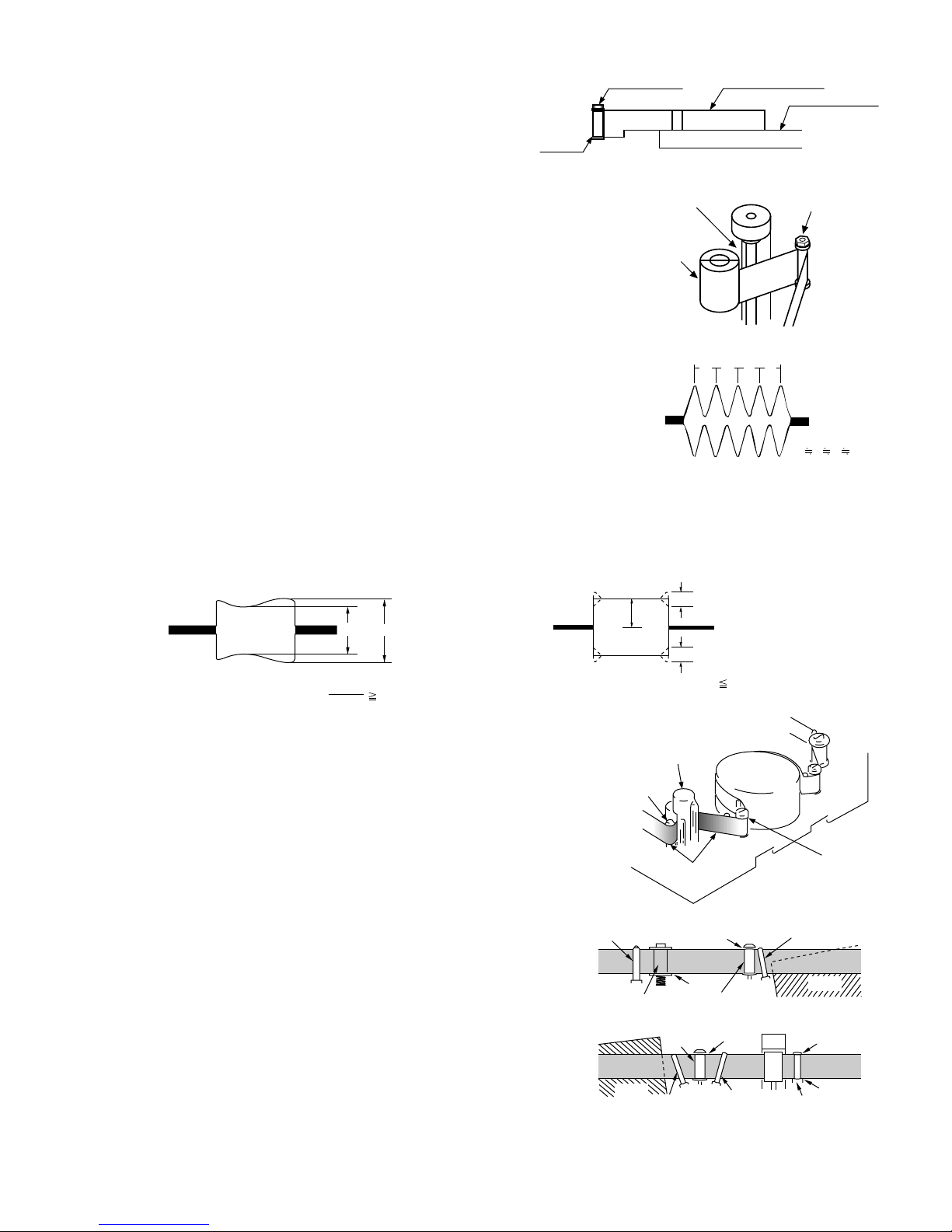
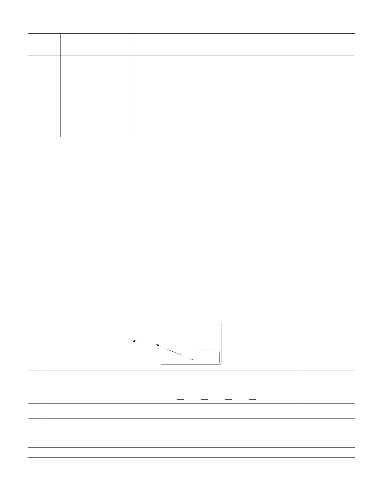
4-2-2. Notes and cautions
(1) Any cut washers, once removed for parts replacement or for other
reason, must be replaced with new ones.
(2) The mechanism of this VCR does not involve any volume adjustment.
If the specified range is not satisfied, either cleaning or replacing the
parts is required.
(3) Oils
a) Be sure to use the specified oils (different viscosity may cause
troubles).
b) For the bearings, be sure to use oil that is free form dust and other
foreign substances. (Dust or foreign substance contained in the oil
may cause wear or seizure of the bearings.)
c) A drop of oil represents the amount of oil which is held on the needle
top as shown in the figure 1.
(4) The circuit repair must be executed without removing the V frame.
(5) For operating the mechanism alone, actuate it with the motor. The
terminal-to-terminal voltage must be DC4V or less.
(6) When installing the cassette control, press the part A shown in Figure
2.
*Do not press other parts.
(7) Take care so that the whole mechanism is not deformed.
4-2
Oil
Diameter φ1.5 or less
Figure 1
A
Figure 2
VL-H870U
VL-H860S/H/VL-H870S
VL-H875U
VL-H890S/VL-H94E
VL-H890U
VL-H96E/VL-H960E
VL-H860S/H/VL-H870S
VL-H890S/VL-H94E
VL-H96E/VL-H960E
4-3. MECHANISM CHECKS AND ADJUSTMENTS
The description given below relates to the general field services, but does not relate to the adjustment and replacement that require
high level equipments, jigs, and technical skills.
In order to maintain the initial characteristics of the machine, it is necessary to execute the maintenance and check and to prevent
damage to tapes and other parts. For adjustments which need jigs, be sure to use the jigs.
Notes and cautions
(1) For mechanism checks and adjustments, be sure to use the AC adapter as the power supply.
(2) For running the tape, be sure to install the cassette control ass’y in advance. (If the cassette control ass’y is to be removed
subsequently after its installation.)
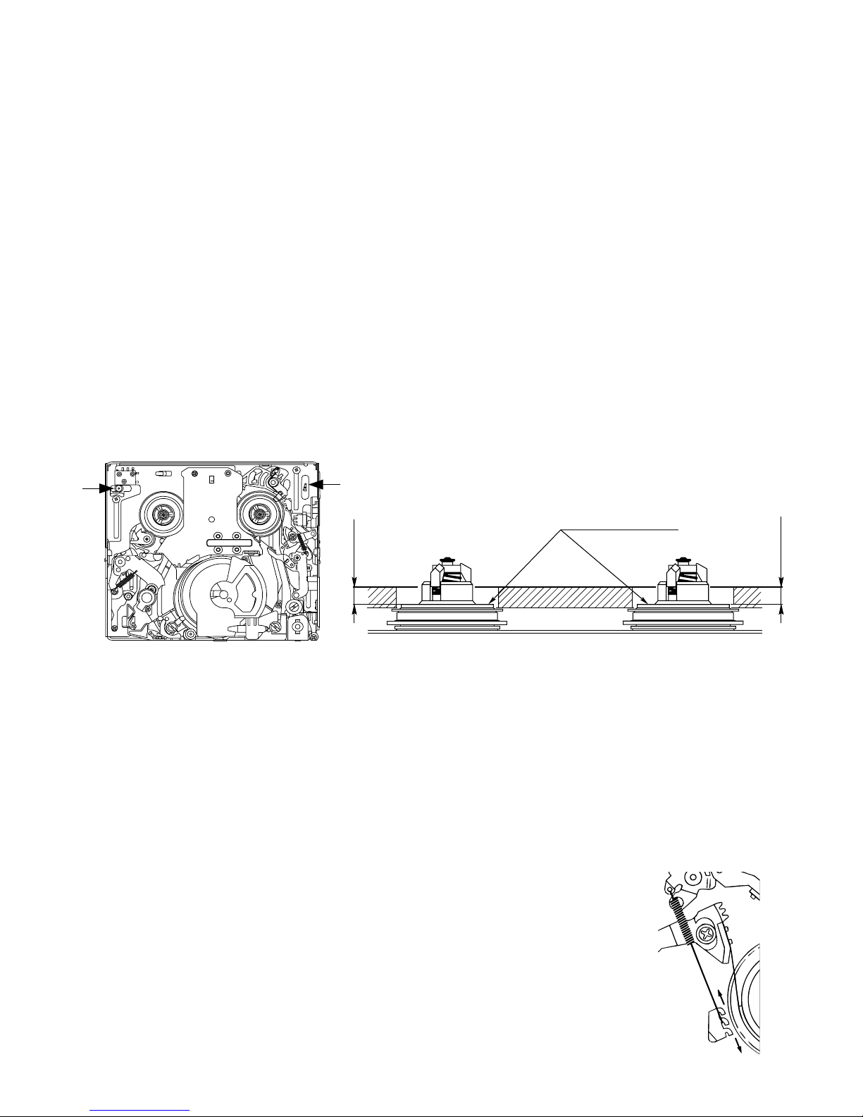
4-3-1. Checking the reel disk height
(1) Remove the cassette control ass’y.
(2) Taking due care not to let the master plane touch the tape running areas such as the drum and the guide rollers, position the
master plane so that the two guides (A and B in the figure 1) are set in the holes of master plane, then properly set it in the
mechanism.
(3) Using the slide callipers or the like, check that the distance from the upper surface of master plane to the reel support surface
of the S/Tu reel disk is within the specified range. (Figure 2)
Note:
When measuring, do not apply excessive force to the reel support surface of reel disk.
(4) If the measurement is not within the specified range, replace the reel disk ass’y.
(5) Check the items (2) to (4) above in the following two modes.
a) Standby mode
b) Playback (recording) mode
B
A
Reel support surface
4.4 ± 0.15
Figure 2Figure 1
4-3-2. Checking the take-up torque for playback (recording)
(1) Set the torque cassette (JiG8T-012) in position, and check in the SP-mode recording mode (tape recorded in SP mode) that
the torque at the tape taking-up side is within the standard range.
Standard of take-up torque for SP-mode recording (playback)
9 ± 3 g·cm with ripples less than 4 g·cm
(If the torque ripples appear, read the center value of torque between the ripples.)
4-3-3. Checking and adjusting the back tension torque for playback (recording)
(1) Checking
1) Set the torque cassette (JiG8T-012) in position, and check in the SP-mode recording mode
(tape recorded in SP mode) that the torque at the tape supply side is within the standard
range.
Standard of back tension torque for SP-mode recording (playback):
8 ± 2 g·cm with ripples of less than 2 g·cm
(Torque ripple must be within 8 ± 2g·cm)
(2) Adjustment
1) If the back tension torque is not within the standard range, adjust the tension spring hooking
position. If the back tension is too high, hook the spring in the direction A. If the back tension
is too low, hook the spring in the direction B.
Note:
1. After back tension torque adjustment be sure to check the tension pole position.
A
B
4.4 ± 0.15
4-3
VL-H860S/H/VL-H870S
3 – 0.5
0
Si roller
Tension pole
T Band
Holder B
Screw
(a)
(B)
Hole (C)
(A)
VL-H890S/VL-H94E
VL-H96E/VL-H960E
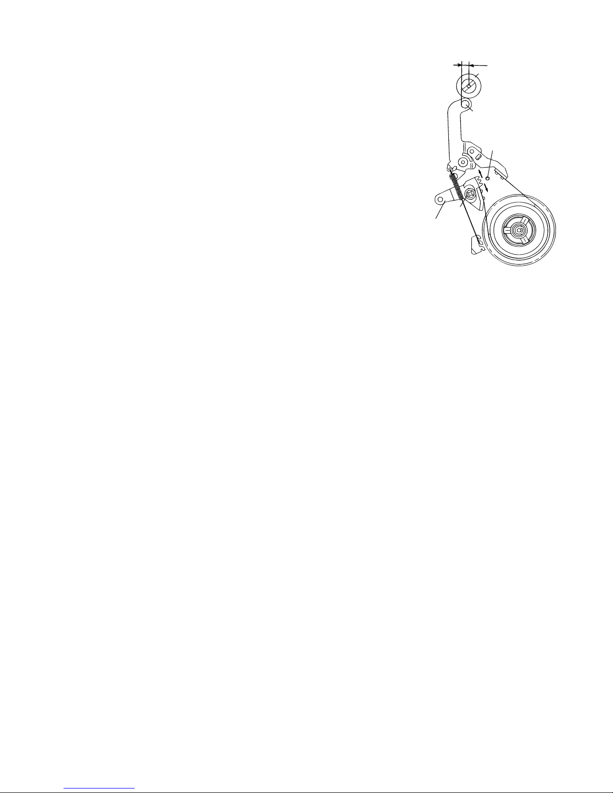
4-3-4. Checking and adjusting the tension pole position
(1) Check
When winding of P5-90 tape is started, check whether the tension pole is in the
specified position against Si roller as shown or not.
If it is not in the specified position, remove the cassette and adjust the position
in the following procedure.
(2) Adjustment
1. Don’t set up any tape, and select the PB mode. (Refer to Item 4-5-1-(4).)
2. Slightly loosen the screw (a) (to such a strength as the T band holder B can
be moved).
3. If the tension pole is in the inner position than specified, dislocate the T band
holder B in the arrow (A) direction and if it is in the outer position, dislocate it
in the arrow (B) position. Then, tighten the screw (a). (For reference, dislocate
it 0.4 to 0.8 mm outer from the position specified above.) For the position
adjustment, it is convenient to use the position adjustment screwdriver
(JiGDRiVERMX7U2). (Set it in the hole (C).)
4. Check the position in the “(1) Check” procedure described above.
5. If it is not in the specified position, repeat the adjusting procedure 1 thru 3.
Note:
• Tightening torque of screw (a) 70 mN·m
• To check the position, be sure to run the tape.
• If the cassette compartment assembly is removed, it makes the work easier. (Refer
to Item 4-5-3.)
VL-H860S/H/VL-H870S
VL-H890S/VL-H94E
VL-H96E/VL-H960E
VL-H870U
VL-H875U
VL-H890U
4-3-5. Checking the take-up torque for rewind playback (VS-REW)
(1) Remove the cassette compartment ass'y and set to the sensor OFF mode.
(2) Set the torque gauge (JiGTG0045) on the S reel disk, and check in the rewind playback (VS-REW) that the torque at the supply
side is within the specified range.
Standard of take-up torque in rewind playback (SP mode)
31 ± 5 g·cm with ripples less than 5 g·cm.
(If the torque ripples appear, read the center value of torque between the ripples.)
4-3-6. Checking the back tension torque for rewind playback (VS-REW)
(1) Set the torque cassette (JiG8T-032) in position, and check in the rewind playback (VS-REW) mode that the torque at the tape
take-up side is within the specified range.
Standard of back tension torque in rewind playback (SP mode):
14 ± 5 g·cm with ripples less than 5 g·cm
(If the torque ripples appear, read the center value of torque between the ripples.)
4-4
VL-H870U
Drum
Reel
Tension pole
Si roller
Sup GR
Sup tilted pole
Tu tilted pole A
Tu GR
Tu tilted pole B
Capstan shaft
Tu guide
Pinch roller
Upper flange
Lower
flange
Height adjusting jig
Master plane
(JiGMP-MX7U)
g
Rise waveform
REV OK Playback
REV NG Playback
VL-H860S/H/VL-H870S
VL-H875U
VL-H890S/VL-H94E
VL-H890U
VL-H96E/VL-H960E
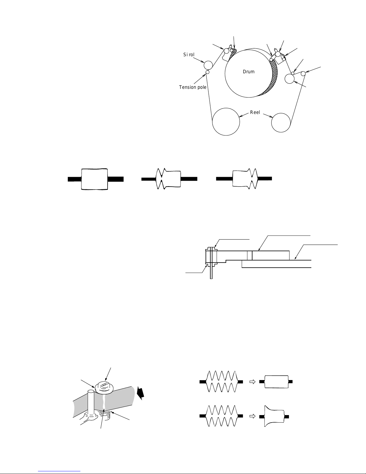
4-4. ADJUSTMENT OF MECHANISM TAPE TRAVEL SYSTEM
4-4-1. Preparation for adjustment
(1) Clean the tape running areas (guide poles, rollers, drum,
Capstan shaft, Pinch roller) (Figure 1)
(2) Connect the oscilloscope to the following TPs.
RF output..... TL7406
H-SW-P ....... TL7446
GND............. TL7452
(3) Playback the alignment tape (VR2DBOPS).
(4) Ascertain that each guide is free from remarkable curl.
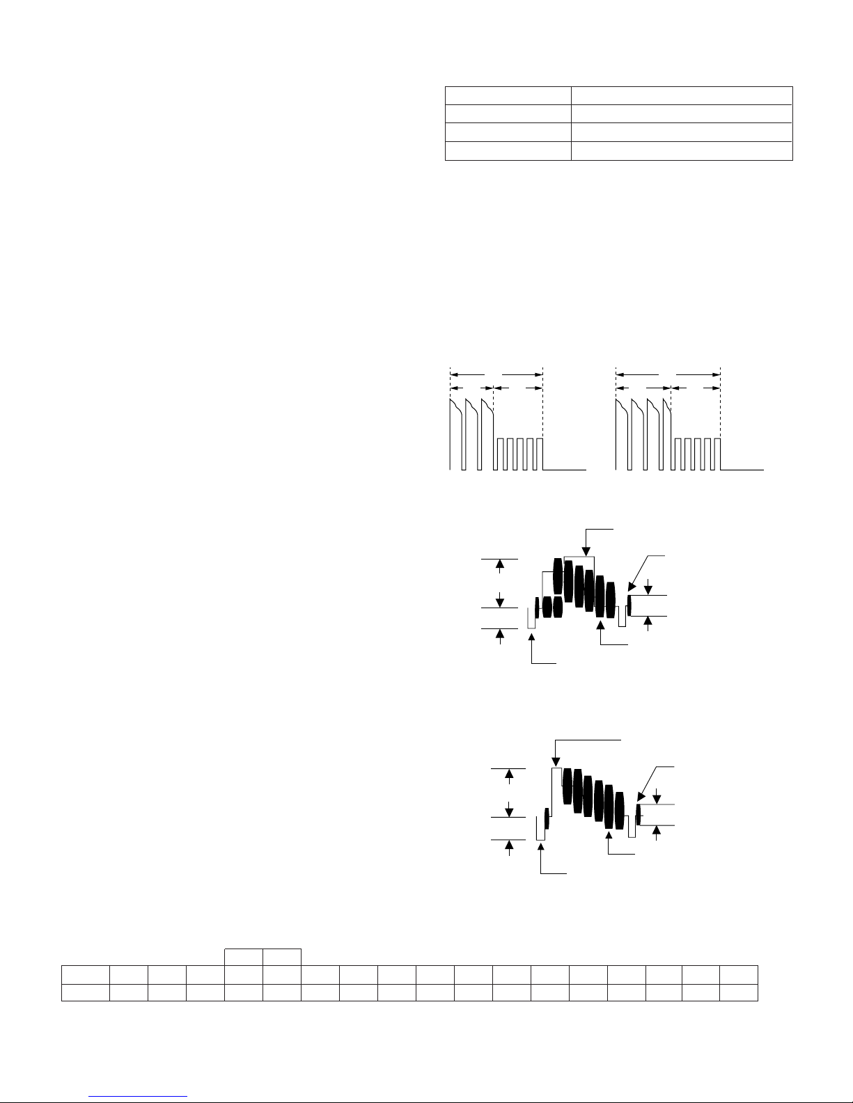
(5) Ascertain that the RF waveform of inlet and outlet sides is flat
on the oscilloscope (Figure 2, (a)). Unless the waveform is
flat, (Figure 2, (b), (c)), make an adjustment as follows.
VL-H860S/H/VL-H870S
VL-H890S/VL-H94E
VL-H96E/VL-H960E
4-4-2. Adjusting the Sup GR and Tu GR
Tape travel system (Figure 1)
(1) Turn the Sup and Tu guide rollers to get the flat waveform at the inlet and outlet sides.
Inlet side Outlet side
(a) Normal
(b) Inlet side
waveform is disturbed.
(c) Outlet side
waveform is disturbed.
Figure 2
4-4-3. Adjusting the Si roller height
After replacement of Si roller preset and adjust the Si roller
height.
(1) Si roller height presetting
Adjust the height from the upper surface ofmechanism chassis to the upper surface of lower flange with the aid of jig. Then
lower it by 90° (clockwise).
Figure 3
(2) Adjusting the Si roller
1 Playback the tape to set the V/SR mode.
2 Ascertain that the tape is not folded on the lower flange (B) of Si roller. (Figure 4)
If tape folding is found, turn the upper flange (A) of Si roller with the driver (clockwise) to eliminate the folding.
3 Playback the alignment tape (VR2DBOPS).
4 Adjust the Sup GR and Tu GR by the procedure described in section 4-2 above.
5 After V/S F,R perform playback so as to ascertain that the waveform rises horizontally within 2 seconds.
6 Unless the normal waveform is obtained (Figure 5), turn counterclockwise the upper flange (A) of Si roller, and repeat the step
(5) above. Repeat the steps (5) and (6) until the normal waveform is obtained. At this time ascertain that the inlet travel does
not change in the normal playback state. If any change is found, adjust the Sup GR, and redo the step (5).
Si roller
Upper flange (A)
REV mode
Tape must be free from folden
Figure 4
Lower flange (B)
.
Figure 5
4-5
VL-H860S/H/VL-H870S
abcd
a b c d
A
C
C
C 1/8A
Capstan shaft
Tu guide
Tape slackness
Tu GR
Tension pole
Si roller
Sup tilted pole
Sup GR
Drum
Drum
Tu GR
Pinch roller
Tu guide
Tu tilted pole
VL-H890S/VL-H94E
VL-H96E/VL-H960E
VL-H860S/H/VL-H870S
VL-H890S/VL-H94E
VL-H96E/VL-H960E
VL-H870U
VL-H875U
VL-H890U
4-4-4. Adjusting the Tu guide
After replacement of Tu guide preset and adjust the height.
(1) Tu guide height presetting
Adjust the height from the upper surface of mechanism chassis to the
upper surface of lower flange with the aid of jig.
(Figure 6)
Lower
flange
(2) Adjusting the Tu guide (Figure 7)
1 Playback the alignment tape (VR2DBOPS).
2 Check that the tape runs at the same height near the capstan shaft in case of
V/S F and V/S R.
3 If the tape running position in case of V/S R is higher than the tape running
position in case of V/S F, turn clockwise the Tu guide nat.
If the tape running position in case of V/S R is lower than the running position
in case of V/S F, turn counterclockwise the Tu guide nat.
4-4-5. Checking the V/S F and R waveforms (Figure 8)
(1) Playback alignment tape (VR2DBOPS), and set the V/S R mode. At this time
ascertain that the waveform crest pitch is kept constant for more than 5 seconds.
(2) Set the V/S F mode. At this time ascertain that the waveform crest pitch is kept
constant for more than 5 seconds.
Unless the constant pitch is obtained, execute the checks of Section 4-2, 3, and
4.
4-4-6. Checking after adjustment
(1) Envelope check
1 Playback the alignment tape (VR2DBOPS).
2 Ascertain that the envelope maximum to minimum ratio is 65% or more. (Figure 9)
3 Ascertain that the waveform does not change remarkably. (Figure 10)
Upper flange
Capstan shaft
Pinch roller
Height setting jig
Master plane
(JiGMP-MX7U)
Figure 6
Nat
Figure 7
Figure 8
Figure 9
(2) Rise check
1 Playback the alignment tape (VR2DBOPS).
2 Once eject the cassette, and then load it again.
3 Set the playback mode, and ascertain that the RF waveform rises horizontally
within 2 seconds. At this time ascertain that there is no tape slackness near
the pinch roller.
4 After V/S F, R and FF/REW execute playback, and ascertain that the RF
waveform rises horizontally within 2 seconds. At this time ascertain that there
is no tape slackness near the pinch roller.
(3) Checking the tape travel
1 When the tape is played back, ascertain that tape lift and tape curl of 0.3 mm
or more do not occur at the lower flange of Si roller, upper flange of Sup GR,
upper flange of Tu GR, and upper/lower flange of Tu guide.
2 In case of V/S F and R ascertain that no curl is found at each flange.
4-4-7. Checking and adjusting the playback switching point
Refer to the description of playback switching point adjustment in section of VCR circuit adjustment.
E
MAX
E
MIN
E
MIN
65 (%)
E
MAX
Figure 10
Figure 11
Figure 12
4-6
VL-H870U
VL-H860S/H/VL-H870S
VL-H875U
VL-H890S/VL-H94E
VL-H890U
VL-H96E/VL-H960E
VL-H860S/H/VL-H870S
VL-H890S/VL-H94E
VL-H96E/VL-H960E
4-5. MECHANISM ASSEMBLING AND PARTS REPLACEMENT
(DISASSEMBLING AND ASSEMBLING)
Below is given an explanation of assembling of mechanism and its parts replacement.
The removal of cabinet and Circuit Board is explained in the relevant service manual.
Notes
1 After removal of cut washers be sure to replace them with new ones.
2 Do not place the mechanism upside down on the table. Otherwise, the mechanism part may be deformed or damaged, resulting
in malfunction.
3 When assembling, take care so that screw, washer or other foreign substance do not enter. Otherwise mechanism malfunction
may occur.
4 Be sure to use the specified cleaning liquid, oil, grease and screw lock as listed below. Otherwise mechanism malfunction may
occur.
Oil: Cosmo Oil Co., Ltd.
COSMOHYDRO HV100
Greases: Dow Coaning
MORYCOAT YM-103/X5-6020
Screw lock: THREE BOND
1401B
Cleaning liquid: Industrial-use ethyl alcohol
4-5-1. Mechanism modes
To actuate the mechanism, apply DC3 to 4V to the L motor. At this time the L motor connector must have been disconnected in advance.
Below is given an explanation of the mechanism mode necessary for mechanism check, adjustment and replacement.
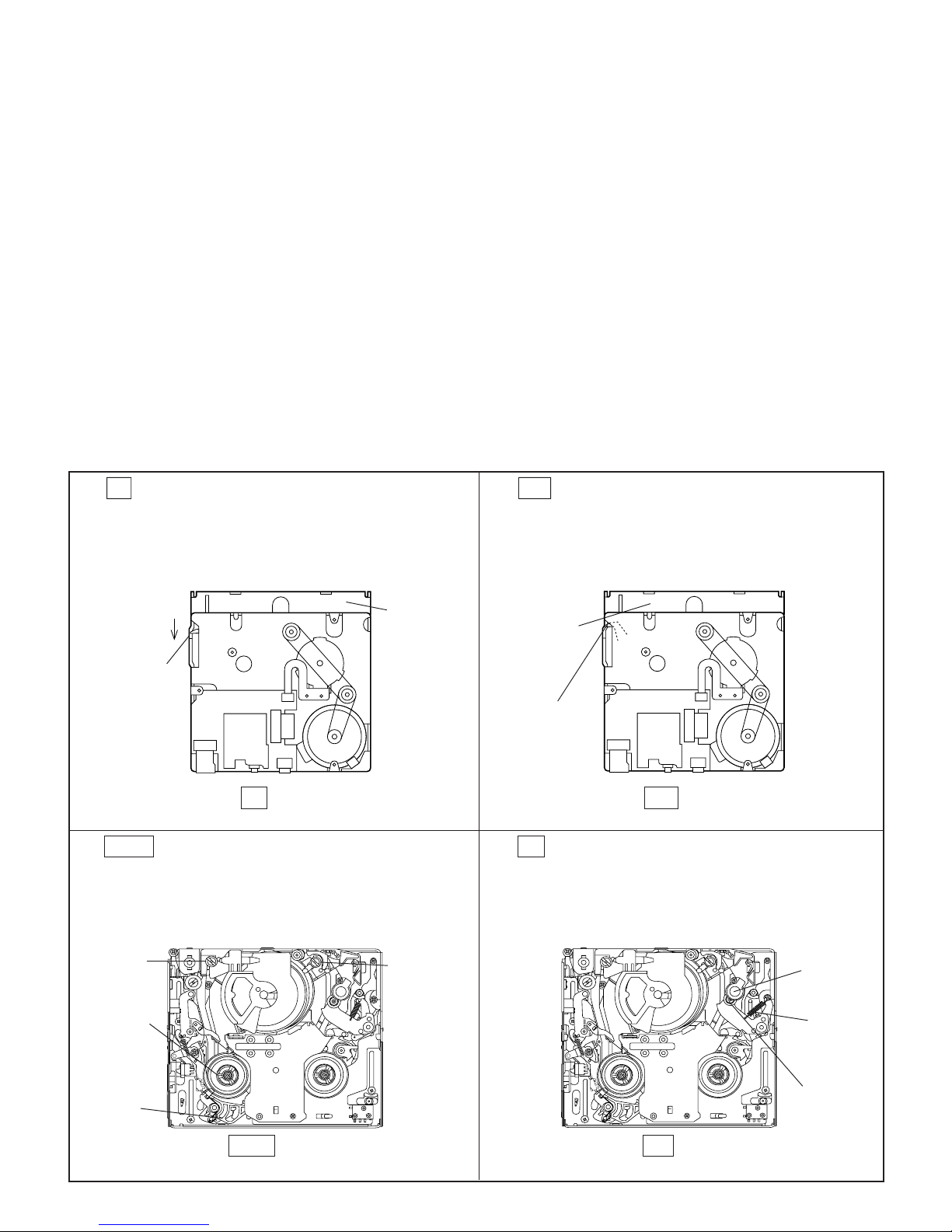
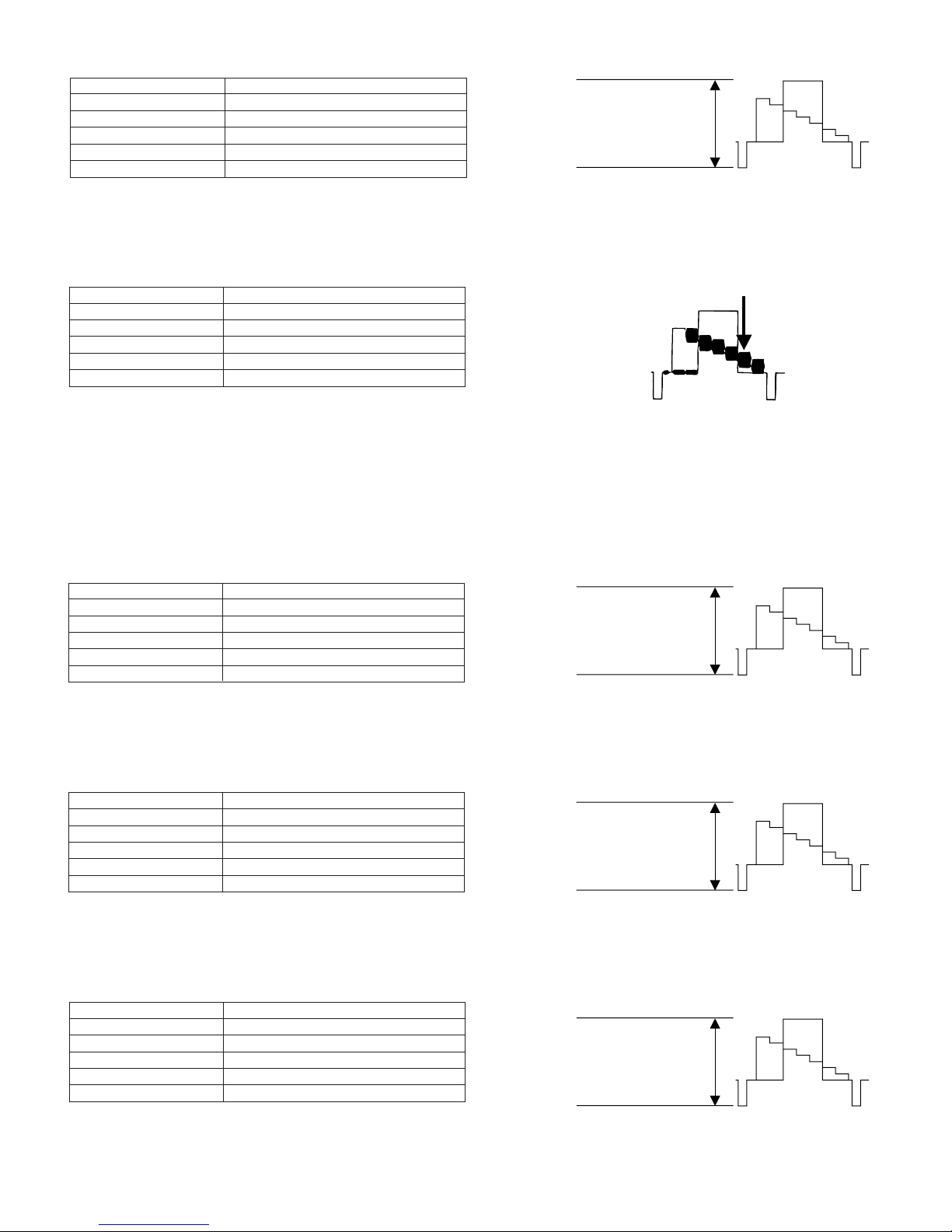
(1). EJ (Eject) mode (See Figure 1)
In this mode, it is mechanically positioned to eject the
cassette. It is the position where the EJECT lever is moved
the farthest in the direction A in the S/B mode. (In this
mode, the cassette compartment assembly can not be
locked.)
A
A
EJECT
Lever
EJ mode
Figure 1
(3). STOP mode (See Figure 3)
In the STOP mode the S.T pole base is depressed in the
STOP position (or Rec Lock position in CAMERA mode),
and the S brake is in contact with the S reel disk.
Slide
chassis
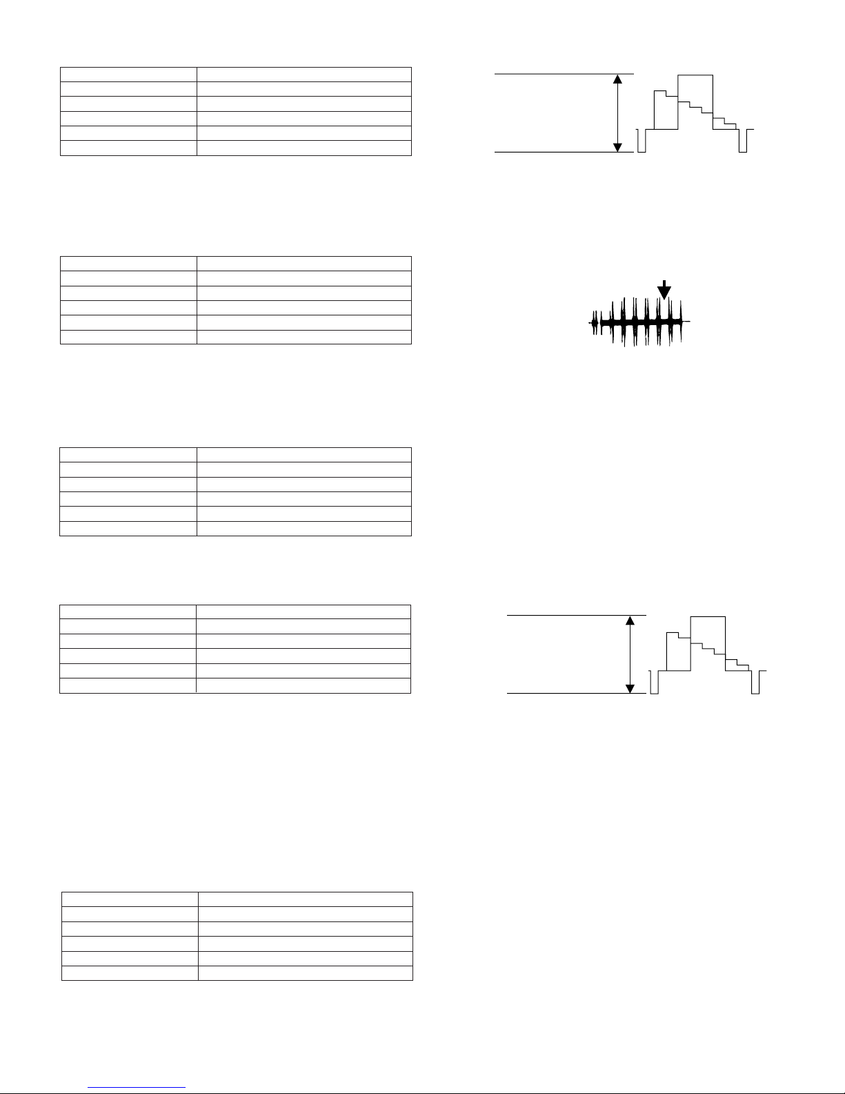
(2). S/B (Standby) mode (See Figure 2)
When the cassette is loaded, the mechanism is set to the
S/B mode. In this mode the slide chassis is most far from
the drum. In this mode the Eject lever is in position shown
in Figure 2 (in position where the cassette control ass’y
can be locked).
Slide
chassis
EJECT
Lever
S/B mode
Figure 2
(4). PB mode (See Figure 4)
In this mode, it is positioned for the replay, record and so
on. It is the mechanical position where the pinch roller is
pressed against the capstan shaft to make the pinchpressing spring the most longest.
S pole base
S reel disk
S brake
STOP mode
Figure 3
T pole base
Capstan
shaft
Pinch
Spring
Pinch roller
PB mode
Figure 4
4-7

VL-H860S/H/VL-H870S
c
i
b
j
a
1
d
f
m
4
m
l
d
k
n
e
e
2
2
2
2
3
i
i
g
f
g
r
c
c
Upper/lower
drum ass'y
Motor stator
Stator mounting
screw
Phase matching
hole
Recognition switch
Cap
Cassette control
down switch
Light guide
Adhesive tape
*
VL-H890S/VL-H94E
VL-H96E/VL-H960E
4-5-2. Cassette control ass’y
<Disassembling>
(1) Set the unit to the EJECT mode, and let the housing stand upright. Or set the
unit to the STANDBY mode, press the lock lever in the arrow direction, and
let the housing stand upright. (See Fig. 5: in the direction
a
pushing in the direction
, slightly lift the housing by hand to release the lock
lever.)
(2) Remove the four screws 2 and take out the down guide 3.
c
(3) Slide the two link support shafts
g
openings
(4) Deflect the roller shafts
g
on the slide chassis. (Be careful not to deform the inner links.)
on their respective slide chassis slits (two at
d
a little inward to get them out of the round openings
and the two roller shafts
<Reassembling>
(1) Set the unit to the STANDBY mode.
(2) Deflect the roller shafts
into the round openings
d
a little inward, and fit them
g
on the slide chassis. (Be
careful not to deform the inner links.)
(3) Align the flanges of roller shafts
f
. While sliding the flanges, fit the support shafts
slits
c
in the slide chassis slits e, and slide them until they
d
with the slide chassis
reach the slits.
(4) Attach the down guide. (While pressing the guide in the
i
direction
, tighten the screws until the gap j between the down guide 3 and the support shafts
becomes zero.)
Tightening torque: 70±7 mN·m (0.7±0.07 kg·cm)
a
e
c
or b) (When
d
to the round
and two at f).
VL-H860S/H/VL-H870S
VL-H890S/VL-H94E
VL-H96E/VL-H960E
Lock Lever
Down Guide
Figure 5. Lock lever section
VL-H870U
VL-H875U
VL-H890U
Screw
4-5-3. Actuating the mechanism with the cassette control ass’y removed
(1) Turn on the power supply with the cabinet and camera unit
removed, referring to the Service Manual (so as to actuate the
mechanism).
(2) Put the cap on the light guide.
(3) Press the cassette control down switch through the adhesive
tape in the arrow direction so as to turn it on. At this time take
care to avoid contact with the cassette. Keep the switch
pressed (if the switch is turned off, unloading occurs).
Note: To set the Rec mode, press the pin (marked with the
asterisk *) of recognition switch (this operation is not
necessary in other modes).
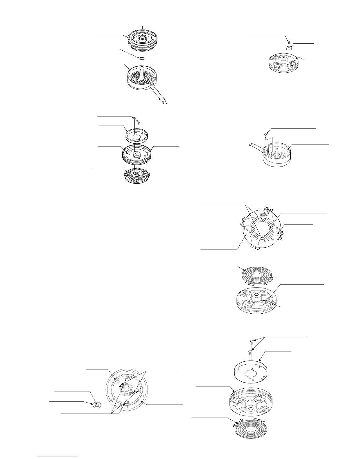
4-5-4. Drum and Drum base
<Removal>
* To replace the upper drum, be sure to put on gloves. Due care is required so that the drum is not damaged.
(1) Drum base
Remove the 3 mounting
screws as shown in Figure 1,
and remove the drum base.
Upper/lower drum ass'y
Mounting
screw
Drum base
Figure 1
Screw tightening
torque (4 locations)
0.069±0.007 N·m
(0.7±0.07kg·cm)
(2) Drum motor stator
Earth spring
Positioning
hole
4-8
Figure 6
Remove the stator
mounting screw with
the hexagonal wrench
as shown in Figure 2,
remove the motor
stator.
Figure 2
VL-H870U
Balancer mounting
screw
Balancer
Upper drum
ass'y
Rotary transformer
rotor
Positioning pin
Cleaning (shaded area)
(holder)
Mounting screw hole
VL-H860S/H/VL-H870S
VL-H875U
VL-H890S/VL-H94E
VL-H890U
VL-H96E/VL-H960E
(3) Upper drum ass’y
Remove the upper drum
ass’y from the lower drum
ass'y as shown in Figure
3.
At this time take care so
as not to lose the gap shim.
Upper drum
ass'y
Gap shim
Lower drum
ass'y
Figure 3
(5) Balancer
Remove the balancer
mounting screw as
shown in Figure 5, and
remove the balancer.
VL-H860S/H/VL-H870S
VL-H890S/VL-H94E
VL-H96E/VL-H960E
Figure 5
(4) Motor rotor ass'y and ro-
tary transformer rotor
ass'y
Rotor mounting
screw
Motor rotor
Remove the 2 rotor
mounting screws as
shown in Figure 4, and
remove the motor rotor
Positioning
hole
Upper drum
ass'y
and the rotary transformer
ass'y.
Positioning pin
Figure 4
<Installation>
Install the upper drum in the reverse order of removal.
(1) Balancer
Mount the balancer to the upper drum ass'y with the balancer
mounting screw. The screw tightening torque must be 0.1N·m
(tighting torque 1kg·cm). (Figure 5)
(2) Motor rotor, rotary transformer rotor ass’y
Clean the contact surfaces of rotor ass’y holder and upper drum
ass'y, and ascertain that there are no contamination and flaws.
Next, adjust the phase so that the positioning pin of rotor ass'y
is inserted into the positioning hole of upper drum, and tight fit
the rotor ass'y to the lower surface of upper drum ass'y (Figure
7).
(6) Lower drum ass'y
Remove the FPC mounting
screw from the lower drum
ass'y as shown in Figure 6.
Rotary transformer
Rotor ass'y
FPC mounting screw
Lower drum ass'y
Figure 6
Positioning hole
To be aligned with
RTr rotor side position
pin.
In this state put the motor rotor on the upper surface of upper
drum ass'y, and tighten the mounting screw. At this time make
sure that the head screw in the three places is visible through
the motor rotor hole (Figure 8). The screw tightening torque
must be 0.1N·m (1 kg·cm).
Motor rotor
Head mounting
screw
Screw relief hole
Alignment position (3 pcs.)
L ch
R ch
Cleaning
Figure 7
Rotor mounting screw
Motor rotor
Mounting screw
Upper drum ass'y
Upper drum ass'y
Rotary transformer
rotor ass'y
Figure 8
4-9
VL-H860S/H/VL-H870S
Motor stator
Stator set
screw
Lo relay gear
Phase
alignment mark
(Round hole)
Phase alignment
mark ( Mark)
Phase alignment mark
(Round hole)
Mode switch
VL-H890S/VL-H94E
VL-H96E/VL-H960E
(3) Lower drum ass'y
Tighten the FPC mounting screw to the lower drum ass'y. The screw
tightening torque must be 0.08N·m (tighting torque 0.8kg·cm). (Figure 6)
(4) Upper drum ass’y
After fitting the gap shim which was removed when the upper drum
ass'y was dismantled to the shaft of lower drum ass’y, fit the upper
drum ass’y. (Figure 3)
At this time slightly turn the upper drum ass'y by hand to ascertain that
RTr does not scrape. If scrape is found, replace the gap shim with the
gap shim packaged together with the replacement upper drum ass’y.
(5) Drum motor stator
Fit the motor stator to the shaft. Then, apply the preliminary pressure
0.07N·m (0.7kg) to the motor stator, tighten the stator mounting
screw. The tightening torque must be 0.15N·m (1.5kg·cm).
Install the stator so that the chassis line is nearly parallel with the
motor stator straight section when it is installed on the chassis.
(Figure 9)
(6) Drum base
Align the positioning pin, and tighten the screws (3 pcs.).
(7) Drum ass’y
Install the drum ass’y on the main chassis, and tighten the screws (3
pcs.).
(8) Tape guide
Align the positioning pin, and tighten the screw (1 pc.).
Arrange parallel.
FPC
VL-H860S/H/VL-H870S
VL-H890S/VL-H94E
VL-H96E/VL-H960E
Chassis line
Motor stator
circuit board
VL-H870U
VL-H875U
VL-H890U
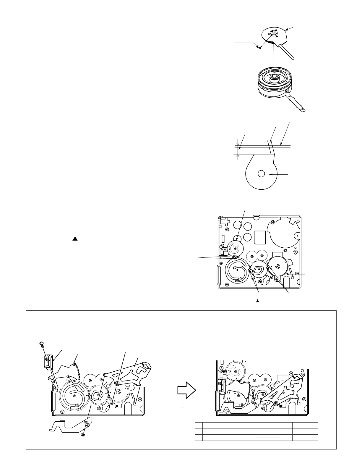
4-5-5. Phase matching
The phase of the following parts must be matched as
shown in the figure below.
(Ascertain that the marks and round holes align.)
(1) Lo relay gear (2) Main cam
(3) Sub-cam (4) Mode switch
4-6. MECHANISM ASSEMBLING METHOD
(1) Adjust the phase of each part.
(2) Install screws and washers.
(3) Install the segment gear, T arm guide and the M-function
lever. Install the eject lever.
a
T arm guide
Segment gear
M-function lever
Figure 9
Move claw to
rear side.
B
Move claw
to rear side.
Item Tightening torque Quantity
a S Tight M1.4 x 3 70mN·m (0.7kgf·cm) 1
B ø0.8-ø3-t0.2 1
4-10

VL-H870U
Make sure not deform the arm.
A
a
A
C
D
B
VL-H860S/H/VL-H870S
VL-H875U
VL-H890S/VL-H94E
VL-H890U
VL-H96E/VL-H960E
VL-H860S/H/VL-H870S
VL-H890S/VL-H94E
VL-H96E/VL-H960E
(4) Install the loading block assembly and the capstan motor.
(5) Install the drive gear. At this time, pay attention to the
direction of gear. (The small gear must be located in the
chassis side.)
a
A
Loading motor
Capstan motor
Move FF
downwards
a
a
a
Install the
motor under
this plate.
(7) Install the guide rail assembly taking care to position it
correctly.
Drive gear
Position the small gear of the drive
towards the chassis.
Item Tightening torque Quantity
(6) Install the guide rail assembly.
A S Tight M1.4 x 2.5 70mN·m 1
a S Tight M1.4 x 3 70mN·m 4
Insert the part in the
rail and slide it down.
Make sure not to
deform the arm.
Item Tightening torque Quantity
A S Tight M1.4 x 2.5 70mN·m 2
B S Tight M1.4 x 4 40mN·m 1
C ø0.8-ø3-t0.2 1
D ø2.1-ø5-t0.25 1
a S Tight M1.4 x 3 70mN·m 1
Align the marks on the parts.
Square Hollow Mark
Round Hole
Triangle Mark
Insert the part in the rail
and slide it down.
4-11
Segment gear
Edge A
Su arm Ass'y
T Lo arm Ass'y
VL-H860S/H/VL-H870S
Take care not to bend the
tension band during assembly
or disassembly.
Pinch lever
Tu guide lever
Tu guide lever SPR
Attach to hook
Attach to hook
Take care of position.
Pinch lever
Stopper
The pinch lever
is positioned on
the stopper.
Secure on back side
B
A
Claw
Claw
Swing arm
VL-H890S/VL-H94E
VL-H96E/VL-H960E
VL-H860S/H/VL-H870S
VL-H890S/VL-H94E
VL-H96E/VL-H960E
VL-H870U
VL-H875U
VL-H890U
(8) Install the drum assembly in the chassis.
(9) Install the tape guide in the drum assembly.
(10) Install the Si roller.
A
A
Si roller
Roller spring
B
Tape guide
Drum assembly
A
(11) Install the slide chassis.
T arm guide
Slide this part towards the T arm.
Place the slide chassis
on the guide rail.
B
Main cam pin
B
Sup reel base
A
B
Insert the main cam pin into the
hole of cam of slide chassis.
Chassis drawing
Item Tightening torque Quantity
A M1.4 x 1.5 ø4 40mN·m 1
B M1.4 x 1.5 ø3.5 40mN·m 3
(12) Install in the following order: T guide lever spring, T guide
lever, pinch lever.
(13) Install the swing arm.
(14) Install the right guide holder.
Item Tightening torque Quantity
A S tight M1.7 x L5.3 100mN·m 3
B S tight M1.7 x L2.5 60mN·m 1
Item Tightening torque Quantity
A S tight M1.4 x 2.5 70mN·m 1
B CW ø0.8-ø3-t0.2 70mN·m 1
4-12

VL-H870U
VL-H860S/H/VL-H870S
VL-H875U
VL-H890S/VL-H94E
VL-H890U
VL-H96E/VL-H960E
VL-H860S/H/VL-H870S
VL-H890S/VL-H94E
VL-H96E/VL-H960E
5. ADJUSTMENT OF VCR AND CAMERA
5-1. INITIAL SETTING OF E2PROM IC
5-1-1. E2PROM data alterable ways
1) Set the switch of main body to CAM, and use the remote control (RRMCG0033TASA) for adjustment to turn on the adjustment
mode.
2) VCR adjustment address setting.
V ADJ
0000 “0000” is blinking
After an objective address was established, play key is pushed and set.
In addition, numerical change uses a “REW” or “FF” key.
3) VCR adjustment data setting.
V ADJ
0000 ## Value of “##” differs by an address.
After an objective data was established, “PLAY” key is pushed and set.
4) When data of other address are changed successively, push “STOP” key, and please repeat operation to 5) from 3).
5) When SW of the substance is turned into off, data are written to E
5-1-2. IC703 (E2PROM)
When the IC703 has been replaced, make the following settings and adjustments.
1. Remove the backup battery (CR2025).
2. Turn power switch to CAMERA.
3. Setting up the V ADJ mode as follows.
* After press the CONTINUE key, press the VCR ADJ key on service remote control (RRMCG0033TASA).
4. After setting the above data, clear the V ADJ mode and turn off the power by pull out the battery pack or DC cable.
Neglect about 30 seconds after turned of power, because data of address becomes effective after microcomputer is reset.
Now the setting of data is completion.
2
PROM from systematic microcomputer.
address data data data data data data data data data data data data
03 (Specificaton code) 28 20 28 28 01 01 01 20 01 01 01 01
02 (Country code) 00 00 00 00 00 00 00 00 00 00 00 00
Adjustments to follow
Make the system controller servo, VCR, and LCD adjustments according to their respective instructions.
H860S H860H H870S H890S H94E H94EW H94EX H96E H96EW H96EX H960E H960EW
5-1-3. Camera adjustment
When the IC2 has been replaced, make the camera adjustment according to its instructions.
All the camera adjustment data are written in the E2PROM provided on the lens unit. Therefore, when the lens is replaced, the
camera must be adjusted again according to the camera adjusting procedure.
5-2. ADJUSTING THE Y/C, AUDIO AND LCD CIRCUITS ON MODELS WITHOUT A/V IN MODE
(A/V IN MODE SET-UP PRODUCE)
1) Set the switch of main body to CAM, and use the remote control (RRMCG0033TASA) for adjustment to turn on the adjustment
mode.
2) Set up the adjustment address (example : EE mode adjustment address 14). Once this address has been set up, the A/V IN mode (test
mode) is automatically brought and the images appear on the LCD display.
3) Now make the adjustments referring to the instruotions in the manual.
5-3. ADJUSTMENT OF VCR SECTION
5-3-1. Before starting the electric circuit adjustment
• Electric circuit adjustment becomes necessary, in most cases, when any of the wear mechanical parts or the video head has been
replaced. Before starting the electric circuit adjustment, be sure to check that the mechanical parts work well (i.e., the mechanical
parts have all been perfectly adjusted). In case a trouble or troubles are found in the electric circuitry, be sure to pinpoint the cause(s)
by using the measuring instruments described below. After locating the trouble spot(s), then proceed to repair, replacement or
adjustment. Do not change the positions of the controls when adequate measuring instruments are not available.
• In order to implement a higher-density, smaller machine, most of the electric circuit parts used on the Circuit Boards are of smallsized, surface-mounted type. For replacing part(s) as after-sales service, work with a soldering iron as speedily as possible. The
heat resistance of the surface-mounted components is poor, when compared with the larger-sized discrete parts used for television
sets and stationary decks, owning to their small sizes. Therefore, exercise due care to avoid long-time exposure of the pins of these
parts to the heat of the soldering iron which may possibly damage them. Such care should be exercised especially for chip-layer
capacitor replacement. It is advisable to use a temperature-controlled ceramic soldering iron (temperature at the tip: 250°C,
contacting time: less than 5 seconds).
5-1
VL-H860S/H/VL-H870S
VL-H890S/VL-H94E
VL-H96E/VL-H960E
VL-H860S/H/VL-H870S
VL-H890S/VL-H94E
VL-H96E/VL-H960E
< Adjusting the video/LCD section >
• Measuring instruments:
*Color monitor TV set *AC adapter *DC cable (AC adapter accessory)
*Digital voltmeter *Oscilloscope *Video extension cables
*DC power supply *Frequency counter *Vector scope
*Audio generator (CR oscillator) *Signal generator
*Alignment tape (JiGWR5-5CSP) *AV output cable (accessory)
(JiGWR5-8CSE) *Video recording tape
(JiGWR5-9CS) (For Y/C, audio and servo adjustments)
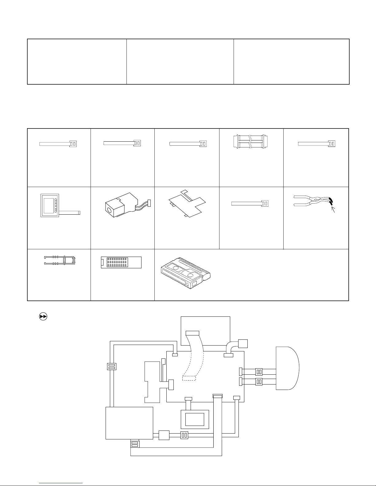
5-3-2. Servicing the VCR section Adjustment
5-3-2-1. Typical connections
<Extension Cable etc.>
12345
Configuration
<Note: The entries of list> 1. Name 2. Part No. 3. Code
4. Note * Model, Uses Remarks
VL-H870U
VL-H875U
VL-H890U
1. Extension Cable
Inverter~VCR (7pin
)
2. QCNW-1265TAZZ
3. AX
6
1. Operation Unit
2. QSW-Z0287TAZZ
3. AW
1. Extension Cable
Camera~VCR (18pin)
2. QCNW-1270TAZZ
3. AY
7
1. DC-IN Jack Unit
2. QJAKZ0069TAZZ
3. AK
1. Extension Cable
Camera~VCR (19pin)
2. QCNW-1381TAZZ
3. AX
8
1. AV Jack Unit
2. QJAKZ0070TAZZ
3. AX
~1
1. Connector fitting and
withdrawing tweezers
2. 9EQPiNSET06GE
1. Service remote control
2. RRMCG0033TASA
3. BT
3. BR
~1 VL-H870/H890/H96/H960
" (FF) Button" functions to as "DISPLAY-button".
~2 It is unnecessary with the VL-H860/H94.
9
1. Extension Cable
MECHA~VCR (70pin)
2. QCNW-1534TAZZ
3. BS
1. Extension Cable LCD~
VCR (24pin)
2. QCNW-1382TAZZ
3. BD
9
1. Extension Cable
Touch Panel (6pin
2. QCNW-1267TAZZ
3. AX
~2
)
1. Connector fitting and
withdrawing extractor
insulating sleeve
· Alignment Tape
JiGWR5-5CSP (PAL) .......Normal 8 TAPE (MONO)
JiGWR5-8CSE (PAL) ......Hi8 TAPE (MONO)
JiGWR5-9CS (PAL).........Hi8 TAPE (STEREO)
* Y/C Audio Alignment
MECHA
UNIT
4
7
LCD
UNIT
8
INVERTER
5
5-2
6
VCR
UNIT
1
2
3
CAMERA
UNIT
VL-H870U
VL-H860S/H/VL-H870S
VL-H875U
VL-H890S/VL-H94E
VL-H890U
VL-H96E/VL-H960E
VL-H860S/H/VL-H870S
VL-H890S/VL-H94E
VL-H96E/VL-H960E
• Types of test modes
TEST No. Sensor on/off
Title
Contents
1 Sensors off All sensors but the cassette controller switch, dew sensor and
battery sensor stay off.
3 Automatic battery sensor Battery sensor’s input voltage put in memory.
adjustment
4 Battery adjustment error Battery sensor’s adjustment errors are displayed at the right of All sensors on
display the “past errors” area. All but sensors
on
5 PASS mode Track shift mode (1/4 shift) All sensors on
6 Camera adjustment mode Camera adjustment mode [VCR
interrupted]
7 VCR adjustment mode VCR adjustment mode
8 Automatic switching point Play standard tape and call this mode. Switching point is
adjustment (STOP ADJ) automatically adjusted.
1 When the battery adjustment mode is selected from the camera adjustment mode with a cassette with the erase protection tab,
the VCR is automatically put in the REC mode.
• Below discussed are these seven test modes.
1 [TEST No. 1] Sensors off mode
All the sensors, except for the cassette controller switch, dew sensor and battery sensor, stay off. This enables
to bring the VCR in the loading mode without tape. The VCR/camera performance can now be checked with no
tape inside.
2 [TEST No. 3] Automatic battery alarm adjustment
Used to automatically adjust the voltage level which makes the “battery” appear on the LCD display.
3 [TEST No. 4] Battery alarm check/error display
• The difference between the preset battery alarm voltage and the current supply voltage is displayed as follows.
• A past error is displayed at the right of the current battery alarm error.
4 [TEST No. 5] PASS mode
Used to adjust the tape travelling condition. The tracking is shifted by 1/4 from the center to make the tape
running-related RF envelope fluctuations easier to observe.
5 [TEST No. 6] Camera adjustment mode
Used to adjust the camera section. (For details, see Servicing the Camera Section.)
6 [TEST No. 7] VCR adjustment mode
Used to adjust the VCR section. (For details, see Servicing the VCR Section.)
7 [TEST No. 8] Automatic switching point adjustment
Used to automatically adjust the playback switching point. (For details, see Automatic Adjustment of the
Playback Switching Point.)
5-3-2-2. Setting up the VCR section adjustment mode (camera section adjustment)
• Select adjustment items by using addresses. Rewrite the adjustment data to change the settings.
Below shown the adjustment procedures and on-screen display.
Enlarged view
(CAM ADJ) camera
V ADJ VCR, LCD
0000 00
(Address) (Data)
Procedural steps
1 Turn up or down the flashing hexadecimal number with the FF or REW key to select the V ADJ
address of a desired adjustment item. (Initial address: 00H)
Note: The addresses change as follows. 01FE 01FF 0000 0001 0002
2 Press the PB key to read the data of the selected address. V ADJ
3 Turn up or down the data setting with the FF or REW key. The data display starts flashing. V ADJ
4 Press the PB key again to write the data setting into the selected address. V ADJ
5 Press the STOP key in the above step 2 or 4, and the screen returns back to the step 1. V ADJ
When the FF or REW key is held down for 0.3 second or longer, the address selection is repeated in cycles of 100 msec. The data
setting changes by ± 4 by holding the key down for 2 seconds or longer.
T-07
V ADJ
0000 00
Display
( : flashing)
002C A3
002C
002C 72
5-3

VL-H860S/H/VL-H870S
VL-H890S/VL-H94E
VL-H96E/VL-H960E
VL-H860S/H/VL-H870S
VL-H890S/VL-H94E
VL-H96E/VL-H960E
5-3-2-3. Battery shut-off voltage adjusting method
1) Supply power to the main unit, using the variable-voltage DC power supply (range of 5V to 9V).
2) Set the CAM/OFF/VCR SW to CAM to switch to the camera mode.
3) Load a recordable tape and set the main unit to CAM REC. PAUSE.
4) Set the main unit to TEST mode No. 3, and start recording.
5) Measure voltage between TL2918(+) and TL2904(GND), and adjust the supply voltage to 6V.
6) The adjustment is complete if "BATTERY" is displayed on the monitor screen for a second when the PLAY key of operation unit
is pressed.
7) The adjustment is regarded as proper if the auto shut-off is actuated after the warning is displayed when the TEST mode is
cancelled.
* In case of automatic adjustment of shut-off voltage, adjustment is impossible if voltage is above 6V ± 0.2V.
If the adjustment is made at 5.8V or below, the low-voltage operation may become unstable.
•Type of test modes
<Procedues>
To adjust the camera section of this machine, the remote control for servicing (RRMCG0033TASA) is used.
Press the "CONTINUE" key → "TEST SEL", this will show [T-01] on the LCD OSD, (01:flashing), and select the below TEST No. with
"FF" or :REW" key and set with "PLAY" key.
Same procedures of adjustment from now on.
Use the SW2 thru SW9 switches on the adjustment tool to select the following test modes.
VL-H870U
VL-H875U
VL-H890U
TEST No. Title
Contents
Sensor on/off
1 Sensors off All sensors but the cassette controller switch, dew sensor and
battery sensor stay off.
2 Mechanism adjustment 1 Automatic SP/LP detection prohibited All sensors on
mode 2 Different-mode detection prohibited
3 ATF sampling limited to center
3 Automatic battery sensor Battery sensor’s input voltage put in memory.
adjustment
4 Error display Past errors appear on the counter display of the viewfinder. All sensors on
Battery adjustment error Battery sensor’s adjustment errors are displayed at the right of the All but sensors
display “past errors” area. on
5 PASS mode Track shift mode (1/4 shift) All sensors on
6 Camera adjustment mode Camera adjustment mode [VCR
interrupted]
7 VCR adjustment mode VCR adjustment mode
8 Automatic switching point Play standard tape and call this mode. Switching point is
adjustment (STOP ADJ) automatically adjusted.
1 When the battery adjustment mode is selected from the camera adjustment mode with a cassette with the erase protection tab,
the VCR is automatically put in the REC mode.
5-4
VL-H870U
VL-H860S/H/VL-H870S
VL-H875U
VL-H890S/VL-H94E
VL-H890U
VL-H96E/VL-H960E
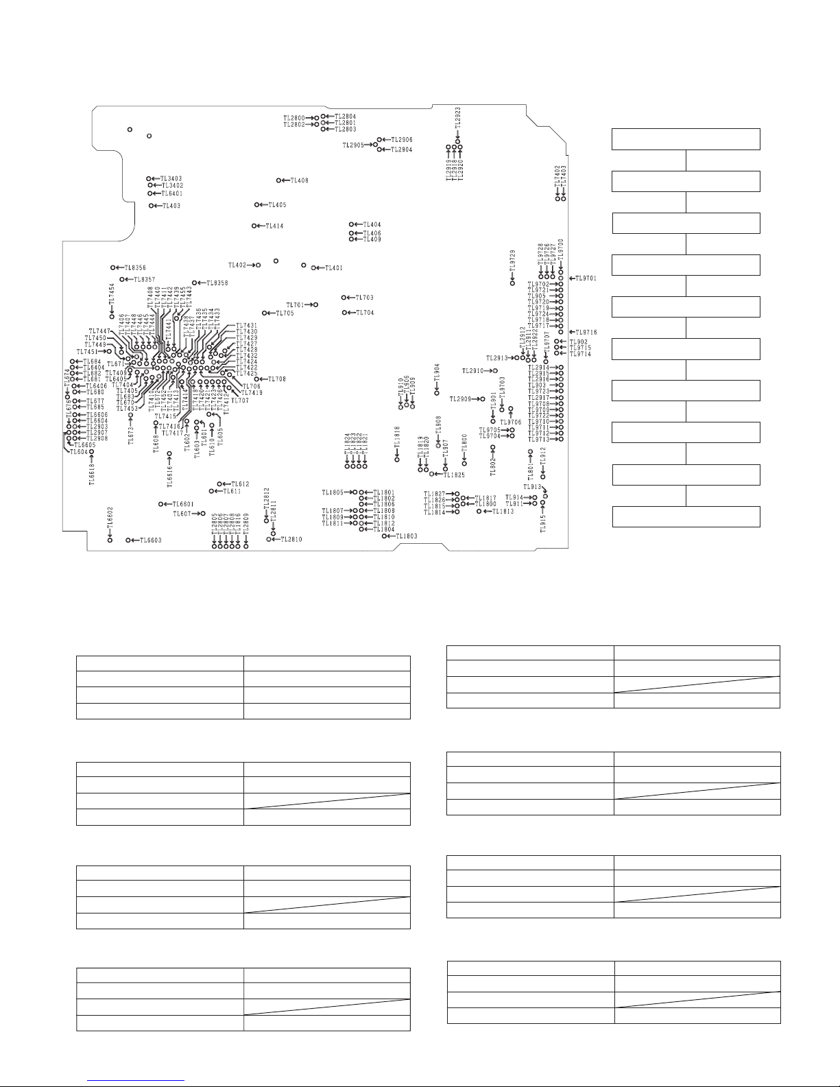
5-3-3. Adjusting the VCR circuit
• Test Points on the Video Circuit Board
VL-H860S/H/VL-H870S
VL-H890S/VL-H94E
VL-H96E/VL-H960E
5-3-3-1. Adjusting the power
circuit
a) POWER CIRCUIT ADJUSTMENT
PROCEDURE
Turn on power (camera).
û
1. Adjust to CAM 15V.
û
2. Check P-CON 4.9V.
û
3. Check P-CON 3.3V.
û
4. Check CAM 2.9V.
û
5. Check LCD 13.5V.
û
6. Check LCD 7V.
û
POWER CIRCUIT ADJUSTMENT METHOD
Æ Input 9V from DC Jack, and set the power switch to the camera side.
` Don't fail to fix the back light unit befor adjusting them.
1. Adjustment to CAM 15V
5. Checking of LCD 13.5V
Make an adjustment so that the digital voltmeter indicates 15V
± 0.05V.
Measuring instrument Digital voltmeter
Measuring terminal TL905
Adjustment address 3EH
Standard 15V ± 0.05V
2. Checking of P-CON 4.9V
6. Checking of LCD 7V
Check that the digital voltmeter indicates 4.9V ± 0.1V.
Measuring instrument Digital voltmeter
Measuring terminal TL901
Adjustment address
Standard 4.9V ± 0.1V
7. Checking of LCD -15.2V
3. Checking of P-CON 3.3V
Ascertain that the digital voltmeter indicates 3.3V ± 0.1V.
Measuring instrument Digital voltmeter
Measuring terminal TL903
Adjustment address
Standard 3.3V ± 0.1V
8. Checking of LCD -7V
4. Checking of CAM 2.9V
Ascertain that the digital voltmeter indicates -7V +0.4/-0.7V.
Ascertain that the digital voltmeter indicates 2.9V ± 0.1V.
Measuring instrument Digital voltmeter
Measuring terminal TL910
Adjustment address
Standard 2.9V ± 0.1V
Æ Turn off power supply.
7. Check LCD -15.2V.
û
8. Check LCD -7V.
û
Æ Turn off power.
Ascertain that the digital voltmeter indicates 13.5V ± 0.2V.
Measuring instrument Digital voltmeter
Measuring terminal TL907
Adjustment address
Standard 13.5V ± 0.2V
Ascertain that the digital voltmeter indicates 7V +0.4/-0.2V.
Measuring instrument Digital voltmeter
Measuring terminal TL904
Adjustment address
Standard 7V +0.4/-0.2V
Ascertain that the digital voltmeter indicates -15.2V ± 1V.
Measuring instrument Digital voltmeter
Measuring terminal TL906
Adjustment address
Standard -15.2V ± 1V
Measuring instrument Digital voltmeter
Measuring terminal TL908
Adjustment address
Standard -7V +0.4/-0.7V
5-5
VL-H860S/H/VL-H870S
6H
3H 3H
V sync signal
6H
3H 3H
V sync signal
Horizontal sync signal
Red (approx. 0.6 V )
Approx. 0.3 V
White (approx. 100%)
Burst signal
Approx. 0.7 V
Approx. 0.3 V
p-p
p-p
p-p
p-p
Horizontal sync signal
White (approx. 100%)
Burst signal
Approx. 0.3 V
p-p
Approx. 0.7 V
p-p
Approx. 0.3 V
p-p
Red (approx. 0.6 V )
p-p
VL-H890S/VL-H94E
VL-H96E/VL-H960E
VL-H860S/H/VL-H870S
VL-H890S/VL-H94E
VL-H96E/VL-H960E
5-3-4. Adjustment of system controller and servo circuit
5-3-4-1. Adjustment of playback switching point
b) CHARGING CIRCUIT ADJUSTMENT PROCEDURE
1) Play back the alignment tape (JiGWR5-5CSP)
2)Press the “CONTINUOUS PUSH” and “TEST MODE SELECTION” of adjustment remote controller to set the test mode.
Measuring instrument
Mode Playback
Adjustment address 30h
Tape Alignment tape (JiGWR5-5CSP)
(At this time the numeral of “TEST01” blinks.)
3)Using the “FF” and “REW” keys, select “TEST08”, and press the playback key to set the SW-P adjustment mode.
4)After a while the adjustment is completed, and operation stops automatically.
In case of adjustment failure the tape is ejected automatically.
Only in the case when the satisfactory result was not obtained by the adjusting method described above, perform the following
adjustment.
1)Connect each signal to the oscilloscope.
1ch: Video output..... TL3402
2ch: H-SW-P ............ TL404
GND: GND ................. TL7449
2)Play back the alignment tape (JiGWR5-5CSP)
3)Press the “CONTINUOUS PUSH” and “VCR ADJUSTMENT” of adjustment remote controller to set the VCR adjustment mode.
4)Select the address 30h, set the sync slope of oscilloscope to (–),
adjust the data with “REW” and “FF” so that the interval between
the trigger point and the V sync signal is set to 6H, and fix the data
with the “PLAY” button. (See Figure 5.1.1.)
5)Then, set the sync slope to (+), and ascertain that the interval
between the trigger point and the V sync signal has been set to 6H.
(See Figure 5.1.2.)
6)Keep the STOP key pressed for about 3 seconds to exit from the
adjustment mode.
Figure 5.1.1
Oscilloscope
Figure 5.1.2
VL-H870U
VL-H875U
VL-H890U
5-3-5. Y/C circuit adjustment method
Input signal conditions
Video signals generated by a pattern generator are used
to make electric adjustments in a Y/C circuit. Thus this
signal must conform to the standards prescribed for adjustment signals.
Use an oscilloscope to check that the video signal is
terminated with a 75 Ω resistor, the amplitude of the sync
signal component, video component and burst signal are
approx. 0.3 Vp-p, 0.7 Vp-p and 0.3 Vp-p, respectively and
that they are flat. The relative level of the burst signal and
the red signal shall be 0.30:0.66.
The color bar used in an electrical adjustment is shown in
Figure A.
* When a pattern generator is not used
Shoot a color bar chart (JiGCHART-4) using a perfectly
adjusted video camera.
A signal from a perfectly adjusted video camera shooting
a color bar chart (JiGCHART-4) can be used as an adjusting signal if the lighting can be set to meet the following
conditions: output (75 Ω terminated), the amplitude of the
sync signal component, video component and burst signal
are approx. 0.3 Vp-p, 0.7 Vp-p and 0.3 Vp-p, respectively.
The relative level of the burst signal and the red signal shall
be 0.30:0.66. This is shown in Figure B.
Figure A Color bar signal produced by a pattern generator
Figure B Color bar signal produced by a video camera
1. Adjustment of fixed data writing
ADD 67 68 69 *6A *6A 6B 6C 6D 6E 6F 55 5A 66 54 65 5C 64
DATA 01 00 02 *00 *01 C8 00 00 66 11 FE C0 FE FE FE C0 C0
Before starting Y/C adjustment, be sure to write the specific data in the addresses listed left.
If the data listed left is written after Y/C adjustment, adjusting values may deviate.
* As for S · H, after all conditioning (VCR circuit) is shut down, Data of 6A is changed in accordance with the above table.
S · H E
5-6
VL-H870U
500 ± 20 mVp-p
Minimum chroma component
500 ± 20 mVp-p
500 ± 20 mVp-p
500 ± 20 mVp-p
VL-H860S/H/VL-H870S
VL-H875U
VL-H890S/VL-H94E
VL-H890U
VL-H96E/VL-H960E
2. Adjustment of EE Y level
Measuring instrument Oscilloscope
Mode VCR STOP
Input signal Color bar
Measuring point TL3402, TL8356 (GND)
Adjustment address 32
Adjustment level 500 ± 20 mVp-p
(1)Input the color bar signal into the video input/output terminal in the VCR STOP mode.
(2)Enter the VCR adjustment mode with an adjustment remote control, and select the address 32.
Select the address, using the FF or REW key, and fix it with the PB key.
(3)Make an adjustment so as to get 500 mVp-p between SYNC TIP and WHITE PEAK on TL3402.
Select the data, using the FF or REW key, and fix it with the PB key.
After the adjustment, press the STOP key, and exit from the adjustment address 32.
3. Adjustment of comb filter
Measuring instrument Oscilloscope
Mode VCR STOP
Input signal Color bar
Measuring point TL414, TL8356 (GND)
Adjustment address Phase: 36, Gain: 37
Adjustment level Minimum chroma component
(1)Input the color bar signal into the video input/output terminal in the VCR STOP mode.
(2)Enter the VCR adjustment mode with an adjustment remote control, and select the address 36.
Select the address, using the FF or REW key, and fix it with the PB key.
(3)Make an adjustment so as to minimize the chroma component on TL414.
Select the data, using the FF or REW key, and fix it with the PB key.
After the adjustment, press the STOP key, and exit from the adjustment address 36.
(4)Enter the VCR adjustment mode with an adjustment remote control, and select the address 37.
Select the address, using the FF or REW key, and fix it with the PB key.
(5)Make an adjustment so as to minimize the chroma component on TL414.
Select the data, using the FF or REW key, and fix it with the PB key.
After the adjustment, press the STOP key, and exit from the adjustment address 37.
(6)Repeat the steps (2) - (3).
4. Adjustment of Y emphasis level
Measuring instrument Oscilloscope
Mode VCR STOP
Input signal Color bar
Measuring point TL408, TL8356(GND)
Adjustment address 56
Adjustment level 500 ± 20 mVp-p
(1)Input the color bar signal into the video input/output terminal in the VCR STOP mode.
(2)Enter the VCR adjustment mode with an adjustment remote control, and select the address 56.
Select the address, using the FF or REW key, and fix it with the PB key.
(3)Make an adjustment so as to get 500 mVp-p between SYNC TIP and WHITE PEAK on TL408.
Select the data, using the FF or REW key, and fix it with the PB key.
After the adjustment, press the STOP key, and exit from the adjustment address 56.
5. Adjustment of Y de-emphasis (Hi-8)
Measuring instrument Oscilloscope
Mode PB
Input signal Color bar (JiGWR5-8CSE)
Measuring point TL405, TL8356(GND)
Adjustment address 57
Adjustment level 500 ± 20 mVp-p
(1)Set the color bar tape for alignment (JiGWR5-8CSE).
(2)Enter the VCR adjustment mode with an adjustment remote control, and select the address 57.
Select the address, using the FF or REW key, and fix it with the PB key.
(3)Make an adjustment so as to get 500 mVp-p between SYNC TIP and WHITE PEAK on TL405
Select the data, using the FF or REW key, and fix it with the PB key.
After the adjustment, press the STOP key, and exit from the adjustment address 57.
6. Adjustment of Y de-emphasis (Normal-8)
Measuring instrument Oscilloscope
Mode PB
Input signal Color bar (JiGWR5-5CSP)
Measuring point TL405, TL8356(GND)
Adjustment address 62
Adjustment level 500 ± 20 mVp-p
(1)Set the color bar tape for alignment (JiGWR5-5CSP).
(2)Enter the VCR adjustment mode with an adjustment remote control, and select the address 62.
Select the address, using the FF or REW key, and fix it with the PB key.
(3)Make an adjustment so as to get 500 mVp-p between SYNC TIP and WHITE PEAK on TL405.
Select the data, using the FF or REW key, and fix it with the PB key.
After the adjustment, press the STOP key, and exit from the adjustment address 62.
5-7
VL-H860S/H/VL-H870S
VL-H890S/VL-H94E
VL-H96E/VL-H960E
VL-H860S/H/VL-H870S
500 ± 20 mVp-p
500 ± 20 mVp-p
VL-H890S/VL-H94E
VL-H96E/VL-H960E
7. Adjustment of PB Y level
Measuring instrument Oscilloscope
Mode PB
Input signal Color bar (JiGWR5-8CSE)
Measuring point TL3402, TL8356(GND)
Adjustment address 3F
Adjustment level 500 ± 20 mVp-p
(1)Set the color bar tape for alignment (JiGWR5-8CSE).
(2)Enter the VCR adjustment mode with an adjustment remote control, and select the address 3F.
Select the address, using the FF or REW key, and fix it with the PB key.
(3)Make an adjustment so as to get 500 mVp-p between SYNC TIP and WHITE PEAK on TL3402.
Select the data, using the FF or REW key, and fix it with the PB key.
After the adjustment, press the STOP key, and exit from the adjustment address 3F.
8. Adjustment of chroma emphasis f0
Measuring instrument Oscilloscope
Mode VCR STOP
Input signal Color bar
Measuring point TL409, TL8356 (GND)
Adjustment address 38
Adjustment level Minimum chroma component
(1)Input the color bar signal into the video input/output terminal in the VCR STOP mode.
(2)Enter the VCR adjustment mode with an adjustment remote control, and select the address 38.
Select the address, using the FF or REW key, and fix it with the PB key.
(3)Make an adjustment so as to get minimum chroma component on TL409.
Select the data, using the FF or REW key, and fix it with the PB key.
After the adjustment, press the STOP key, and exit from the adjustment address 38.
VL-H860S/H/VL-H870S
VL-H890S/VL-H94E
VL-H96E/VL-H960E
Minimum chroma component
VL-H870U
VL-H875U
VL-H890U
9. Adjustment of Y-FM carrier (Hi-8)
Measuring instrument Frequensy counter
Mode VCR STOP
Input signal No input
Measuring point TL7443
Adjustment address 33
Adjustment level 5.99 ± 0.02kHz
10. Adjustment of Y-FM deviation (Hi-8)
Measuring instrument Oscilloscope
Mode RWC/PB (self-playback/recording)
Input signal Color bar
Measuring point TL3402
Adjustment address 34
Adjustment level 500 ± 20 mVp-p
(1)Set the recordable tape.
(2)Before entering the adjustment mode,make self-playback/recording of color bar with an external output.
Measure whether the playback output at this time is 500 mVp-p on TL3402 (Hi8 TAPE).
(3)Enter the VCR adjustment mode with an adjustment remote control, and select the address 34.
Select the address, using the FF or REW key, and fix it with the PB key.
(4)When decreasing by 10 mVp-p as compared to the measurement value of (2), decrease the data of address 34 by about 5 (digit).
(Reference)
When increasing by 10 mVp-p as compared to the measurement value of (2), increase the data of address 34 by about 5 (digit).
(Reference)
Select the address, using the FF or REW key, and fix it with the PB key.
(5)Release the adjustment mode, and make self-playback/recording again. When the measuring value at this time is in the standard
value, the adjustment is completed. If it is not in the standard value, repeat the steps (2) -(4).
(6)After completing the adjustment of (5), check the adjusting value of Y-FM carrier f0 (5.99 MHz in no input).
When the measuring value exceeds the standard value of carrier f0, make an adjustment of Y-FM carrier f0 again.
11. Adjustment of Y-FM carier f0 (Normal-8)
Measuring instrument Ferquensy counter
Mode VCR STOP
Input signal No input
Measuring point TL7443
Adjustment address 60
Adjustment level 4.38 ± 0.02 MHz
(1) Input the no-signal into the video input/output terminal in the VCR
STOP mode.
At this time, do not pull out the jack on the Viewcam side.
(2) Enter the VCR adjustment mode with an adjustment remote
control, and select the address 33.
Select the address, using the FF or REW key, and fix it with the PB
key.
(3) Make an adjustment so that the frequency counter indicates
5.99MHz on TL7443.
Select the data, using the FF or REW key, and fix it with the PB key.
After the adjustment, press the STOP key, and exit from the
adjustment address 33.
(1)Input the no-signal into the video input/output terminal in the
VCR STOP mode.
At this time, do not pull out the jack on the Viewcam side.
(2) Enter the VCR adjustment mode with an adjustment remote
control, and select the address 60.
Select the address, using the FF or REW key, and fix it with the
PB key.
(3) Make an adjustment so that the frequency counter indicates
4.38 MHz on TL7443.
Select the data, using the FF or REW key, and fix it with the PB
key.
After the adjustment, press the STOP key, and exit from the
adjustment address 60.
5-8
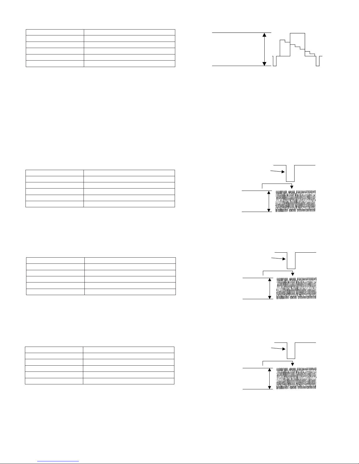
VL-H870U
500 ± 20 mVp-p
530 mVp-p
SYNC
(TL3402)
360 mVp-p
SYNC
(TL3402)
510 mVp-p
SYNC
(TL3402)
VL-H860S/H/VL-H870S
VL-H875U
VL-H890S/VL-H94E
VL-H890U
VL-H96E/VL-H960E
VL-H860S/H/VL-H870S
VL-H890S/VL-H94E
VL-H96E/VL-H960E
12. Adjustment of Y-FM deviation (Normal-8)
Measuring instrument Oscilloscope
Mode REC/PB (self-playback/recording)
Input signal Color bar
Measuring point TL3402
Adjustment address 61
Adjustment level 500 ± 20 mVp-p
(1)Set the recordable tape.
(2)Before entering the adjustment mode,make self-playback/recording of color bar with an external output.
Measure whether the playback output at this time is 500 mVp-p on TL3402 (Nor 8 TAPE).
(3)Enter the VCR adjustment mode with an adjustment remote control, and select the address 61.
Select the address, using the FF or REW key, and fix it with the PB key.
(4)When decreasing by 10 mVp-p as compared to the measurement value of (2), decrease the data of address 61 by about 5 (digit).
(Reference)
When increasing by 10 mVp-p as compared to the measurement value of (2), increase the data of address 61 by about 5 (digit).
(Reference)
Select the address, using the FF or REW key, and fix it with the PB key.
(5)Release the adjustment mode, and make self-playback/recording again. When the measuring value at this time is in the standard
value, the adjustment is completed. If it is not in the standard value, repeat the steps (2) -(4).
(6)After completing the adjustment of (5), check the adjusting value of Y-FM carrier f0 (4.38 MHz in no input).
When the measuring value exceeds the standard value of carrier f0, make an adjustment of Y-FM carrier f0 again.
13. Adjustment of REC-Y equalizer (Hi-8 ME)
Measuring instrument Oscilloscope
Mode VCR STOP
Input signal Color bar
Measuring point TL7443
Adjustment address 58
Adjustment level 530 ± 20 mVp-p
(1)Input the color bar signal into the video input/output terminal in the VCR STOP mode.
(2)Enter the VCR adjustment mode with an adjustment remote control, and select the address 58.
Select the address, using the FF or REW key, and fix it with the PB key.
(3)Make an adjustment so that the SYNC TIP portion gets 530 mVp-p on TL7443.
Select the data, using the FF or REW key, and fix it with the PB key.
After the adjustment, press the STOP key, and exit from the adjustment address 58.
14. Adjustment of REC-Y equalizer (Hi-8 MP)
Measuring instrument Oscilloscope
Mode VCR STOP
Input signal Color bar
Measuring point TL7443
Adjustment address 31
Adjustment level 360 ± 20 mVp-p
(1)Input the color bar signal into the video input/output terminal in the VCR STOP mode.
(2)Enter the VCR adjustment mode with an adjustment remote control, and select the address 31.
Select the address, using the FF or REW key, and fix it with the PB key.
(3)Make an adjustment so that the SYNC TIP portion gets 360 mVp-p on TL7443.
Select the data, using the FF or REW key, and fix it with the PB key.
After the adjustment, press the STOP key, and exit from the adjustment address 31.
15. Adjustment of REC-Y equalizer (Normal-8 ME)
Measuring instrument Oscilloscope
Mode VCR STOP
Input signal Color bar
Measuring point TL7443
Adjustment address 63
Adjustment level 510 ± 20 mVp-p
(1)Input the color bar signal into the video input/output terminal in the VCR STOP mode.
(2)Enter the VCR adjustment mode with an adjustment remote control, and select the address 63.
Select the address, using the FF or REW key, and fix it with the PB key.
(3)Make an adjustment so that the SYNC TIP portion gets 510 mVp-p on TL7443.
Select the data, using the FF or REW key, and fix it with the PB key.
After the adjustment, press the STOP key, and exit from the adjustment address 63.
5-9
 Loading...