

Sharp VL-E630U/T,VL-E680U,VL-E685U/T Service Manual
yp&yT
VL:E665Urr
SHARP
SERVICE MANUAL
SYBASJL-E630U
LIQUID CRYSTAL CAMCORDER
q
NTSC
VL-E630U/T
VL=E680U
MODELS
VL-E685U/T
In
the
interests
of
user-safety
(Required by
safety regula-
tions in
some
countries)
the
set should be restored to its
original
condition and
only parts
identical to those specified
be used.
CONTENTS
Page
2. SPECIFICATIONS
..............................................................................................................................
2
4. DISASSEMBLY OF THE SET
.............................................................................................................
3
5. MECHANISM ADJUSTMENT..
...........................................................................................................
4
6. ADJUSTMENT OF
VCR..
....................................................................................................................
5
8. SCHEMATIC DIAGRAMS..
................................................................................................................
8
11
.REPLACEMENT PARTS LIST
..........................................................................................................
29
12.PACKlNG OF THE SET
....................................................................................................................
35
SHARP CORPORATlON
This document has been published to be used for
after sales service only.
The contents are subject to change without notice.
~p3o~fr
VL:E685Un
2. SPECIFICATIONS
Signal System:
Recording System:
Cassette:
Recording/Playback Time:
Tape Speed:
Pickup Device:
Lens:
Lens Filter Diameter:
Monitor:
Microphone:
Color Temperature Compensation
Minimum Illumination:
Video Output Level:
Audio Output Level:
Speaker Output:
Power Requirement:
Power Consumption:
Operating Temperature:
Operating Humidity:
Storage Temperature:
Dimensions (approx.):
Weight (approx.):
NTSC standard
2 rotary heads, helical
scanning system
8 mm video tape, MP type
120 minutes (P6-
120)
14.345 mm/second
l/4” (6.4mm, effective size: 4.5 mm) CCD image sensor with approx.
270,000 pixels including optical black
16 x power
zoom
lens (F1.4, f=4.0-64.0 mm) and full-range auto
focus
46 mm
3” (7.5 cm)-full-color LCD screen (TFT active matrix)
Electret monaural microphone
Auto white balance
0.8 lux (5 lux measured by EIA standard) (with gain-up, F1.4)
1 .O Vp-p 75-ohm unbalanced
-8 dBs, impedance less than 2.2 kohms
200 mW
DC 3.6V
E630U:4.8W (during camera recording in full auto mode with zoom
motor off, and backlight in normal mode)
E680U/E685U:4.9W (during camera recording in full auto mode with
zoom motor off, Extend Zoom, DIS and Snapshot functions off, and
backlight in normal mode)
0°C to + 40°C (32°F to 104°F)
30% to 80%
-20°C to +6O”C (-4°F to 140°F)
7 5/32” (W) x 4 g/$ (H) x 3 7/~” (D)
[182 mm (W) x 109 mm (H) x 99 mm (D)]
1.52lbs (690g)
(without battery pack, lithium battery, video cassette, and lens cap)
AC Adapter/Battery Charger Battery Pack BT-H22
UADP-0274TAZZ(VL-E63OU/680U/685U)
UADP-0275TAZZ(VL-E63OT/685T)
DC Output: 3.6V
Dimensions (approx.): 2 l/s” (W) x 3/4” (H) x 2 7/32” (D)
Power Requirement:
DC Output:
Power Consumption:
Dimensions (approx.):
AC 11 O-240
V, 50160
Hz
4.5 v
16W
2
31/32” (W) x 2” (H) x 5 5/16” (D)
r/5mm(W)x51 mm(H)x
135 mm (D)]
0.65 Ibs (295 g)
k$,mmm(OJ x 19 mm
O-4
x
Weight (approx.): 0.30 Ibs (136 g)
Weight (approx.):
Specifications are subject to change without notice.
SERVICE INFORMATION (For the U.S.)
For the location of the nearest Sharp Authorized Service, or to obtain product literature, accessories,
supplies or customer assistance, please call l -800-BE SHARP (l-800-237-4277) or visit SHARP’s
web site (http://www.sharp-usa.com)
4. DISASSEMBLY OFTHE SET
4-2. Disassembly of the VCR main body
1. Removal of the VCR lid shaft
(l)Remove one screw ((j)LX-HZ0063TAFC).
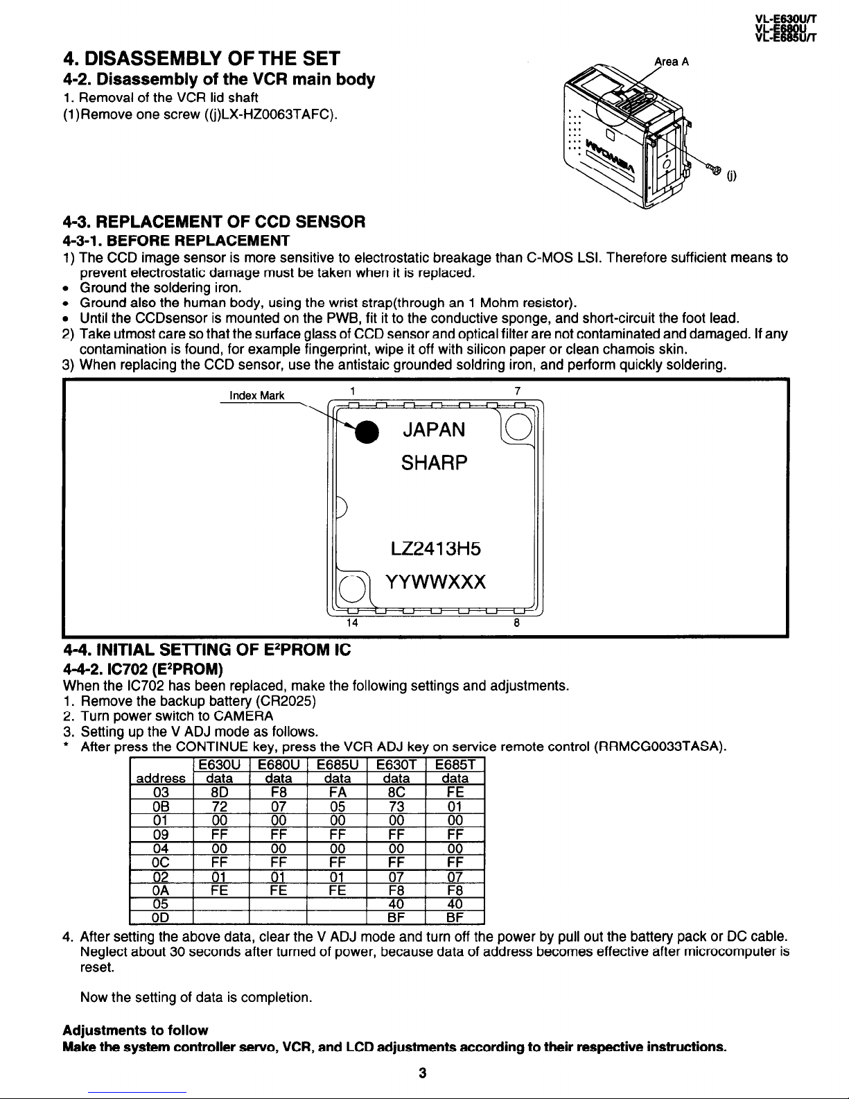
4-3. REPLACEMENT OF CCD SENSOR
4-3-l. BEFORE REPLACEMENT
1) The CCD image sensor is more sensitive to electrostatic breakage than C-MOS LSI. Therefore sufficient means to
prevent electrostatic damage must be taken when it is replaced.
l Ground the soldering iron.
l Ground also the human body, using the wrist strap(through an 1 Mohm resistor).
l Until the CCDsensor is mounted on the PWB, fit it to the conductive sponge, and short-circuit the foot lead.
2) Take utmost care so that the surface glass of CCD sensor and optical filter are not contaminated and damaged. If any
contamination is found, for example fingerprint, wipe it off with silicon paper or clean chamois skin.
3) When replacing the CCD sensor, use the antistaic grounded soldring iron, and perform quickly soldering.
Index Mark
1 7
SHARP
LZ2413H5
4-4. INITIAL SE-KING OF EzPROM IC
4-4-2. IC702 (E*PROM)
When the IC702 has been replaced, make the following settings and adjustments.
Remove the backup battery (CR2029
Turn power switch to CAMERA
Setting up the V ADJ mode as follows.
After press the CONTINUE key, press the VCR ADJ key on service remote control
1.
2.
3.
l
4. _ After setting the above data, clear the V ADJ mode and turn off the power by pull out the battery pack or DC cable.
Neglect about 30 seconds after turned of power, because data of address becomes effective after microcomputer is
reset.
(RRMCG0033TASA).
Now the setting of data is completion.
Adjustments to follow
Make the system controller servo, VCR, and LCD adjustments according to their respective instructions.
3

VL-E63olJ/l
VL-E68ou
VL-E685U/T
5.
MECHANISM
ADJUSTMENT
5-2.
Items and
timings
of inspection and maintenance
5-2-l. Inspection
and maintenance list
-
Remarks
I
CheckingIvlaintenance point 5oo
t-
Usag
E
1,000
,
!
time
1,5oc
hrs.)
Possible symptom
?,OOO 3,000
encountered
cl
cl
l
Lateral
noise
l
Unclean head
l
Screen shaking
cl
cl
no 00
l
Improper S/N ratio
l
No color appears.
* *
l Tape does not run.
l
Tape
slackens.
q
o q
l
Screen
shakes.
0 0
A A
l Abnormal sound
Cl
0
q
-
q
-
-
Rollers
l
If abnormal rotation or
deflection
(signifi-
cant)
is found,
replace
the roller.
Other
than
rollers
*Clean the tape con-
tacting areas. Besure
to use
the
specified
cleaning agent.
.
Replace if failure is
found.
Timing belt
Pinch
roller
Capstan D.D. motor
Relay
Pulle shaft
Pulle gear shaft
Drive gear shaft
cl
-
-
-
A
A
l-l
l
Apply oil.
(Oil:
Note:
)
After oil is applied to
the drive
gear shaft,
slightly wipe it off with
swab.
I
I
l
Not ejectable
l Replace if failure (ab-
*o 90
l
The specific mode can-
normal sound) is de-
not be set.
tected.
l
If conformance to the
standard is not ensured, replace part.
Abnormal sound
sr
PBNS-REW take-up torque
-
PBNS-REW back tension torque
Tu brake
-
HC (Head Cleaner)
-
I
I
1
* *
I I
I
I
*
0
*
I * I
I I
0 : Replace.
0
: Clean.
A :
Apply oil.
+
:
Check.
Oil:
Grease: MORYCOAT YM-103/X5-6020
Screw locking agent: THERE BOND 1401 B
Cleaning liquid: Industrial-use ethyl alcohol
5-4. ADJUSTMENT OF MECHANISM TAPE TRAVEL SYSTEM
5-4-3. Adjusting the Si roller height
(2) Adjusting the Si roller
1 Playback the tape such to set the V/SR mode.
4
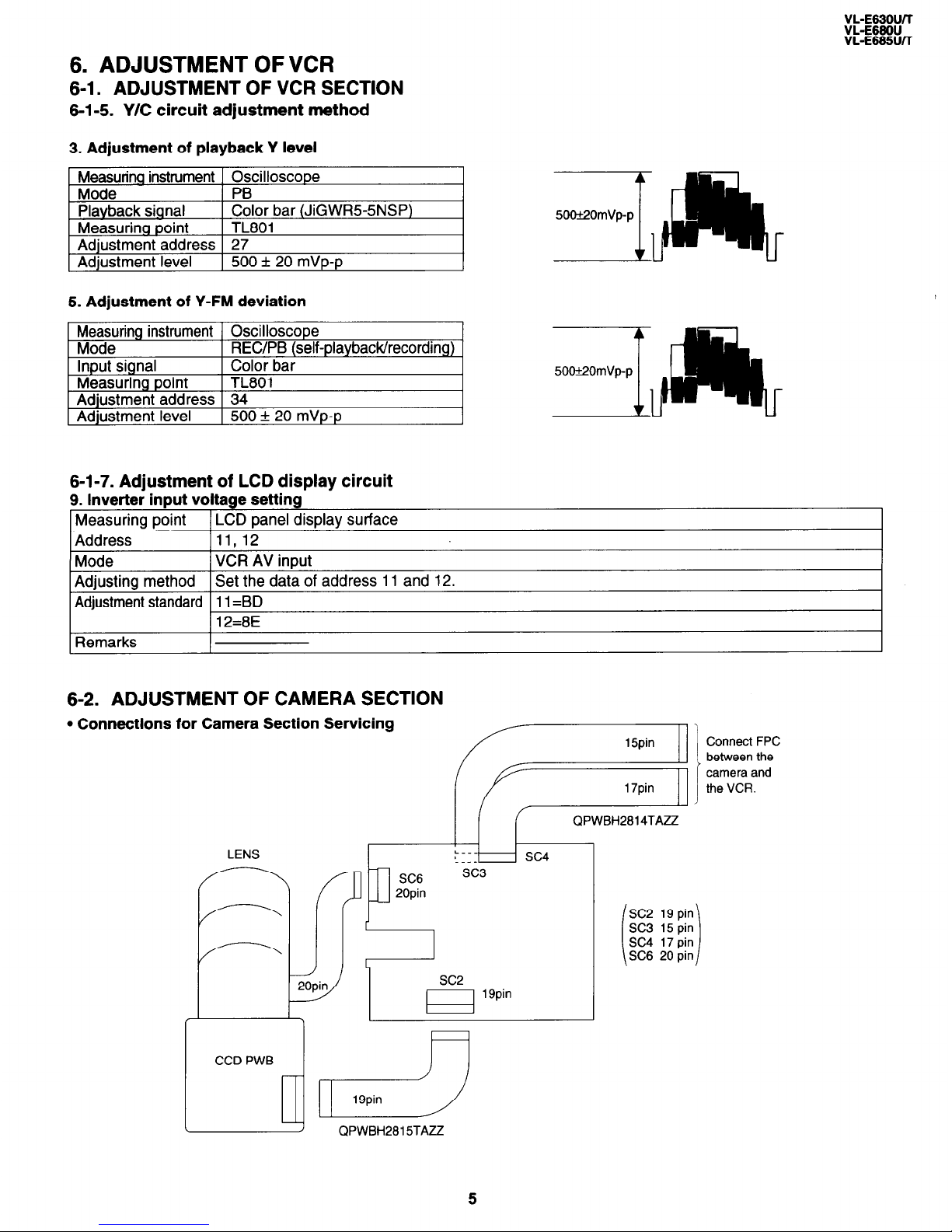
6. ADJUSTMENT OF VCR
6-1. ADJUSTMENT OF VCR SECTION
6-l-5. Y/C circuit adjustment method
3. Adjustment of playback Y level
~,
5. Adjustment of Y-FM deviation
Measuring instrument Oscilloscope
Mode REC/PB (self-playback/recording)
Input signal
Color bar
Measuring point
TL801
Adjustment address 34
Adjustment level 500 f 20 mVp-p
6-l-7. Adjustment of LCD display circuit
9. lnverter input voltage setting
Measuring point
LCD panel display surface
Address 11,12
Mode
VCR AV input
Adjusting method
Set the data of address 11 and 12.
Adjustment standard 11 =BD
12=8E
Remarks
6-2. ADJUSTMENT OF CAMERA SECTION
l Connections for Camera Section Servicing
LENS
F
-
20pin
i
k-----k
CCD PWB
SC3
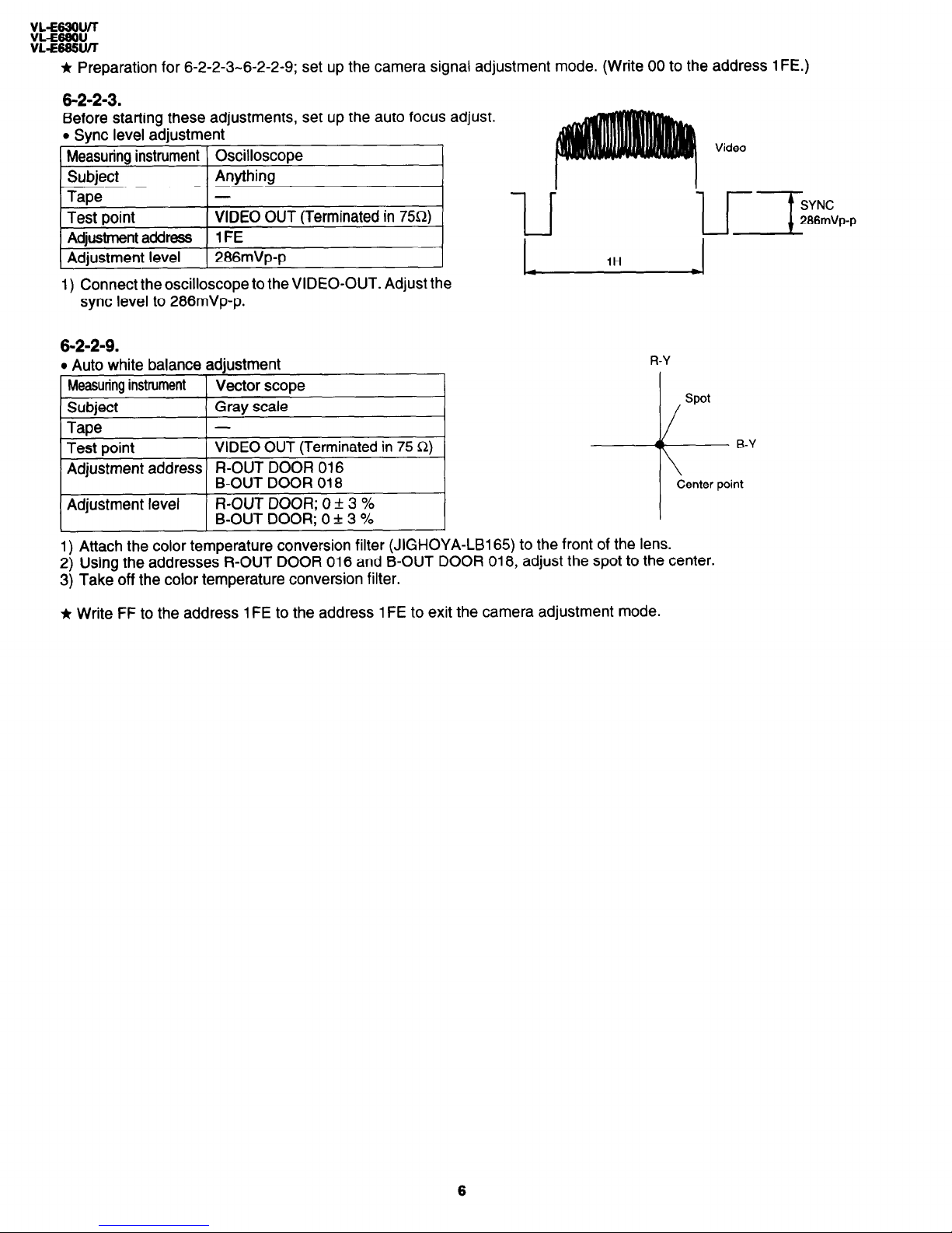
* Preparation for 6-2-2-3-6-2-2-9; set up the camera signal adjustment mode. (Write 00 to the address 1 FE.)
6-2-2-3.
Before starting these adjustments, set up the auto focus adjust.
l Sync level adjustment
Measuring instrument Oscilloscope
Subject
Anything
Tape
-
Test point
VIDEO OUT (Terminated in 75Q)
Adjustment address
1FE
Adjustment level
286mVp-p
1) Connect the oscilloscope to the VIDEO-OUT. Adjust the
sync level to 286mVp-p.
6-2-2-9.
l Auto white balance adjustment
Measuring instrument
Vector scope
Subject
Gray scale
Tape
-
Test point
VIDEO OUT (Terminated in 75 Q)
Adjustment address R-OUT DOOR 016
B-OUT DOOR 018
Adjustment level
R-OUT DOOR; 0 + 3 %
B-OUT DOOR; 0 + 3 %
Video
1H
R-Y
/
spot
1) Attach the color temperature conversion filter (JIGHOYA-LB165) to the front of the lens.
2) Using the addresses R-OUT DOOR 016 and B-OUT DOOR 018, adjust the spot to the center.
3) Take off the color temperature conversion filter.
Ir Write FF to the address 1 FE to the address 1 FE to exit the camera adjustment mode.
-MEMO-
_-_------___-------________________________-_------________-----______-------_____-------_
_____------_____----------______-------_________---__________-_-__________--_________-----
_-______---_______-----________---________________________________________________________
____------______-------____-_-----_____________________-_____________________--________---
_-----___-------___------------~~~----------~___--------____------~__--------~~__--_---~~~
------___--________----__---------________________________________________________________
_-_-_____--________----_____________________________________~________________--________---
~----___------__----------~~~~----------_____-----_____-----_______---______----_____-----
____------_---------__--------________________________________________________--__________
_-_--______-----____-_--------_______---_______---________--_________-________--_______---
______----______----____________________________________________________________________-_
___---________----______------___________________-________--________--_______---_____----~
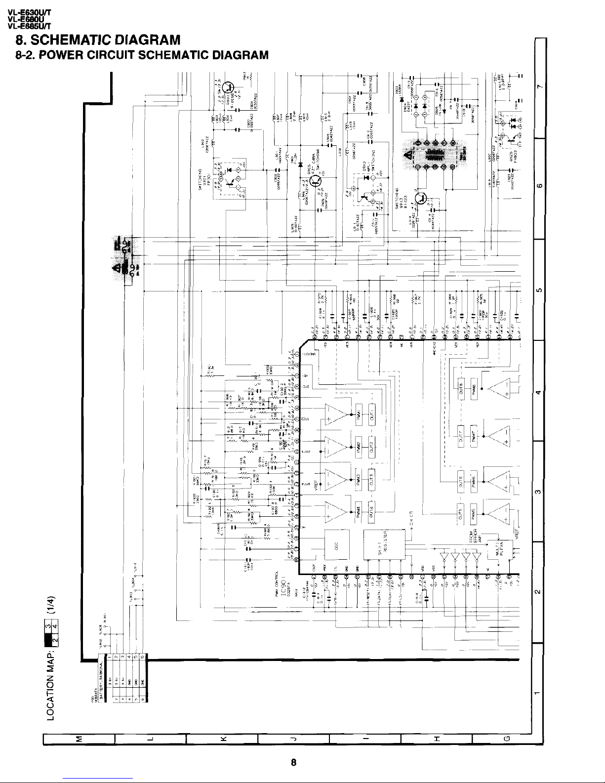
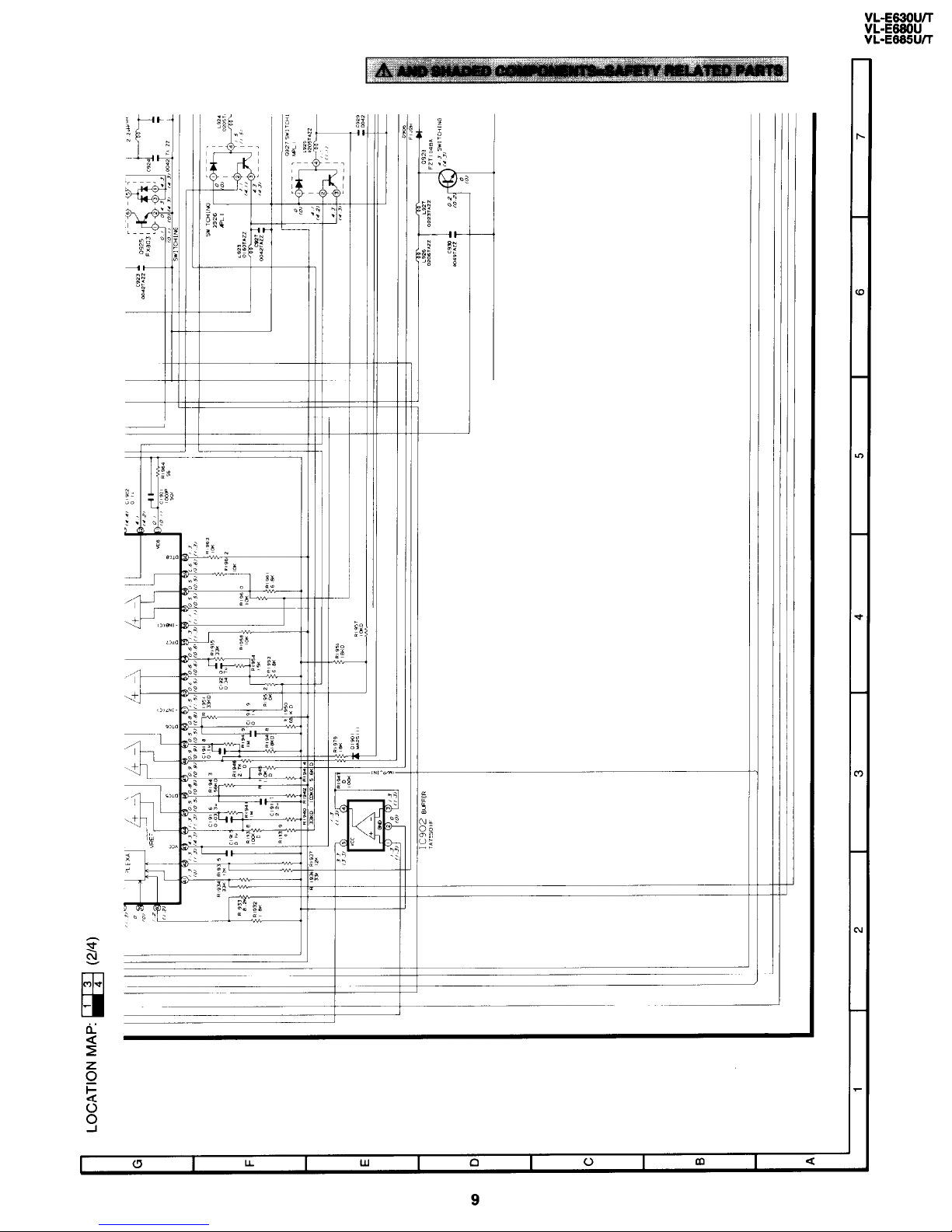
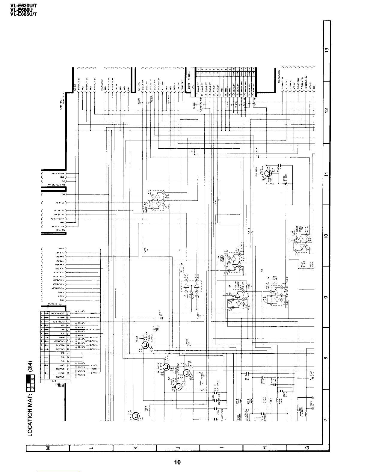
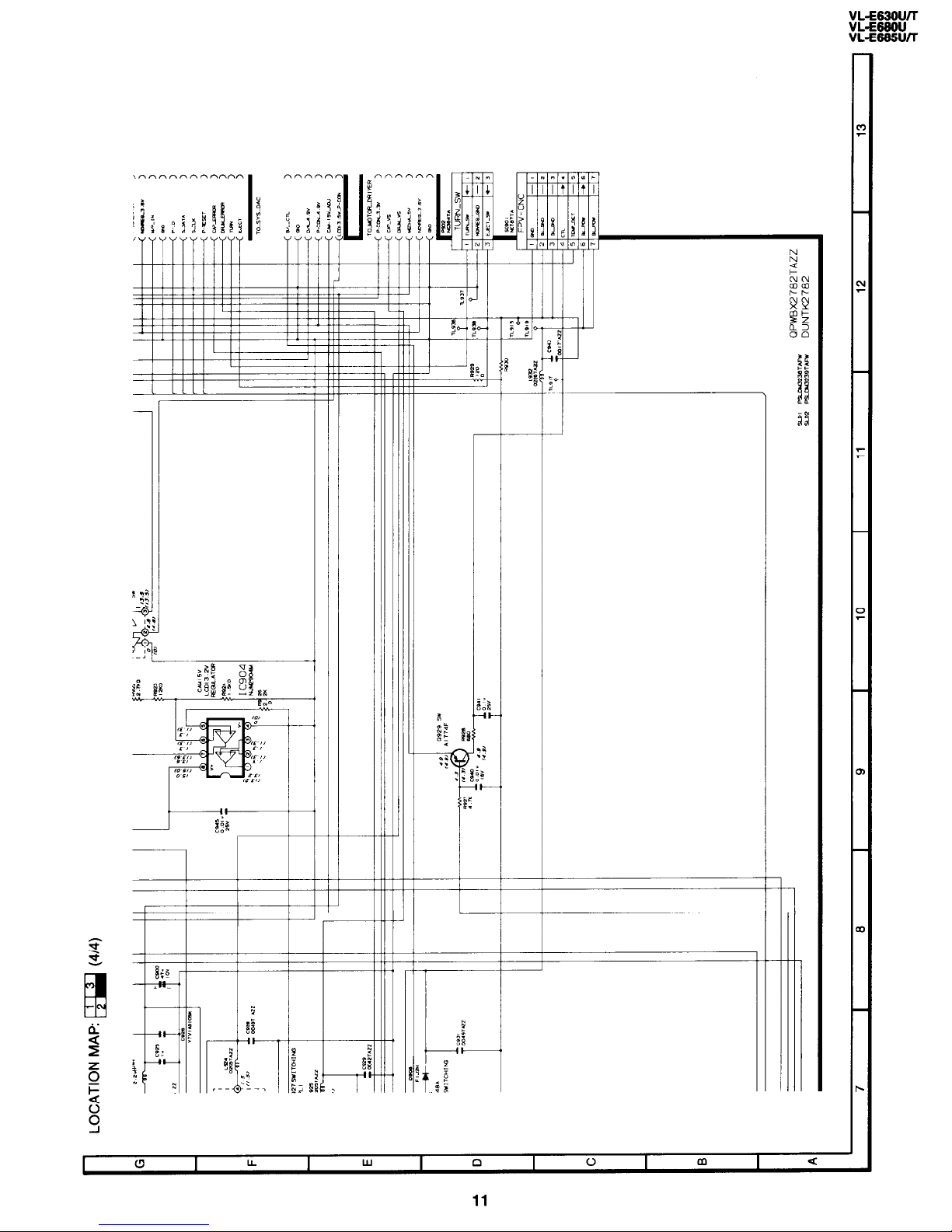
8. SCHEMATIC DIAGRAM
8-2. POWER CIRCUIT SCHEMATIC DIAGRAM
I -
-f
8
VL-E63OWT
VL-E66OU
VL-E66!5U/T
‘t
9
c-
i
/--I
10
_
_
_
_
11
 Loading...