


Sharp VC-A410U, VC-A411U, VC-A420U, VC-H810U, VC-H811U Operating Manual
...
VIDEO CASSETTE RECORDER
OPERATION MANUAL
Please read this operation manual carefully
before using the VCR.
MODEL
VC-A410U VC-A411U VC-A420U VC-H810U VC-H811U VC-H820U
|
TAMPER REMOTE SENSOR |
|
POWER TIMER VCR REC |
PROOF |
SET MENU |
|
|
|
|
|
S.PICTURE |
(VC-H820U)
Information |
General |
|
|
|
|
SettingUp |
|
|
|
|
|
Operations |
Basic |
|
|
|
|
Recording |
|
|
|
|
|
Functions |
Special |
|
|
|
|
Hints |
Helpful |
|
|
[IMPORTANT]
EZ SET UP (AUTO CHANNEL/CLOCK SET UP)
|
|
|
|
|
|
|
|
|
|
|
|
|
|
|
|
|
|
|
|
|
|
|
|
|
|
|
|
|
|
|
|
|
|
|
|
|
|
|
|
|
|
|
|
|
|
|
|
|
|
|
|
|
|
|
|
|
|
|
|
|
|
|
|
|
|
|
|
|
|
! Connect Antenna/Cable |
@ Then, plug into AC |
||||||||||||
to VCR first. |
Power Outlet. |
||||||||||||
|
|
|
|
|
|
|
|
|
|
|
|
|
|
TAMPER |
REMOTE SENSOR |
POWER TIMER VCR REC PROOF
Flashing |
#Do not press the POWER button until completion of EZ SET UP.
TAMPER |
REMOTE SENSOR |
POWER TIMER VCR REC PROOF
Flash slowly |
$ EZ SET UP complete.
Detail: Please see page 15
1
This video cassette recorder (VCR) uses “ONLY” cassette tapes, NTSC video signals and 120 V AC, 60 Hz (standard household current).
For future reference, record the model and serial number (located on the rear of the VCR) in the space provided.
Model No.: —————————
Serial No.: —————————
WARNING:TO REDUCE THE RISK OF FIRE OR ELECTRIC SHOCK, DO NOT
EXPOSE THIS APPLIANCE TO RAIN OR MOISTURE.
CAUTION: TO PREVENT ELECTRIC SHOCK, MATCH WIDE BLADE OF PLUG TO WIDE SLOT, FULLY INSERT.
CAUTION
RISK OF ELECTRIC SHOCK
DO NOT OPEN
CAUTION: TO REDUCE THE RISK OF ELECTRIC SHOCK, DO NOT REMOVE COVER. NO USERSERVICEABLE PARTS INSIDE. REFER SERVICING TO QUALIFIED SERVICE PERSONNEL.
This symbol warns the user of uninsulated voltage within the unit that can cause dangerous electric shocks.
This symbol alerts the user that there are important operating and maintenance instructions in the literature accompanying this unit.
WARNING—Keep your VCR away from electrical and magnetic appliances which could impair performance. Be sure to position your VCR away from your TV or video monitor by at least 8 .
WARNING OF DEW FORMATION
Whenever your VCR is moved from a cold to a warm environment, it is important that you plug the unit in, turn the power on and allow it to sit for about 2 hours before attempting to play a tape. This period will allow any dew formation to evaporate. Failure to do so may result in tape and/or video head damage.
After the 2 hour evaporation period, you may witness a “snowy” picture for the first few minutes of VCR operation. This picture noise will disappear shortly thereafter.
As an ENERGY STAR® Partner, SHARP has determined that this product meets the ENERGY STAR® guidelines for energy efficiency. ENERGY STAR is a U.S. registered mark.
WHAT IS ENERGY STAR®
TVs and VCRs use energy both when they are on and when they are off. North Americans spend more than $1 billion a year of energy consumed by TVs and VCRs when they are not in use. The new ENERGY STAR® models will reduce that energy “leakage” by up to 75 percent. Ultimately, this will mean more than $500 million a year in energy savings for consumers.
The energy savings will help reduce the burning of fossil fuels and the related carbon dioxide pollution that contributes to global warming. If every North American family replaced their TVs and VCRs with ENERGY STAR® models, it would reduce carbon dioxide emissions by five million tons every year -- equivalent to eliminating the pollution from more than one million cars.
By using ENERGY STAR® products, you will save money on your electric bills and use less energy. This not only makes good economic sense but also good for our environment.
2
IMPORTANT SAFEGUARDS AND PRECAUTIONS
CAUTION
READ THE SAFETY AND OPERATING INSTRUCTIONS before operating your VCR. FOLLOW INSTRUCTIONS AND HEED ALL WARNINGS on your VCR and in this manual.
INSTALLATION
1.Operate only from a power source indicated on your VCR or in this manual. If you are unsure of your power supply, ask your local power company.
2.As a safety feature, your VCR is equipped with either a 2-wire polarized plug (one plug blade bigger than the other) or a 3-wire grounded plug (a third pin for grounding). The 2-wire polarized plug will fit only one way into the power outlet. The 3-wire grounded plug will fit only into a grounding-type power outlet.
If the plug does not fit, ask your electrician to replace your obsolete outlet. Do not modify the plug. To do so will void the safety feature.
3.Protect and route power cords so they will not be stepped on or pinched by anything placed on or against them. Be especially careful at plug-ins, convenience receptacles or cord exit points from the VCR. Frayed power cords or damaged plugs are hazardous. Have them replaced by a qualified service technician.
Overloaded wall outlets and extension cords may cause fire or electrical shock hazards.
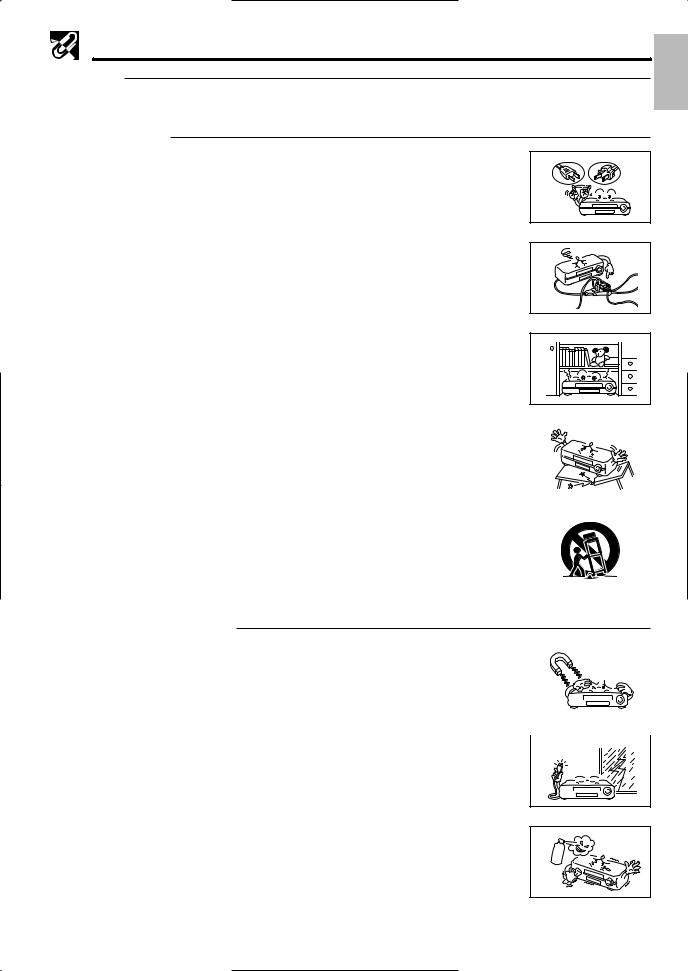
4.Do not cover or block ventilation holes in the VCR cabinet. Doing so may damage the VCR or cassette or cause fire.
2
3
4 |
|
Do not place your VCR on a soft surface which could block ventilation holes on the |
6 |
|
|
bottom. Avoid enclosed installations such as bookshelves or racks unless ventilation |
||
|
|
||
|
is adequate. |
|
|
5. |
Avoid excessive humidity, sudden temperature changes or temperature extremes. |
|
|
|
Dew may form inside your VCR or on the cassette. |
|
|
6. |
To avoid costly damage or injury, place your VCR flat on a solid, stable surface free |
|
|
7 |
|||
|
from vibrations; do not place any heavy objects on top of it. Use only a cart, stand, |
||
|
tripod, bracket or table recommended by the manufacturer; follow all instructions |
|
|
|
regarding their use exactly. |
|
|
7. |
An appliance and cart combination should be moved with care. Quick stops, |
|
|
|
excessive force and uneven surfaces may cause the appliance and cart combination |
|
|
|
|
||
|
to overturn. |
|
OPERATION/CLEANING
1. |
Keep your VCR away from electrical and magnetic appliances which could impair |
1 |
|
|
|
|
|
performance. Be sure to position your VCR away from your TV or video monitor by at |
|
|
|
|
|
|
|
|
|
|
|
|
|
least 8 . |
|
|
|
|
|
2. |
Keep your VCR away from wet locations such as bathtubs, sinks, laundries, wet |
|
|
|
|
|
|
|
|
|
|
||
|
basements and swimming pools. |
|
|
|
|
|
3. |
Use only accessories recommended by the manufacturer to avoid fire, shock or other |
|
|
|
|
|
5 |
|
|
|
|
||
|
hazards. |
|
|
|
|
|
|
|
|||||
4. |
If your VCR has been exposed to rain, moisture or strong impact, unplug it and have |
|
|
|
|
|
|
it inspected by a qualified service technician before resuming use. |
|
|
|
|
|
5.Unplug your VCR and disconnect it from the antenna and/or cable system during a lightning storm or an extended period of discontinued use.
6
6. Unplug your VCR before cleaning. Use a damp cloth for cleaning. Do not use cleaning fluids or aerosols which could enter the unit and cause damage, fire or electrical shock. These substances may also mar the finish of your VCR.
7. Never open or remove covers or make any adjustments not described in this manual. Attempting to do so could expose you to dangerous electrical shock or other hazards. It may also cause serious damage to your VCR.
GeneralInformation
3

IMPORTANT SAFEGUARDS AND PRECAUTIONS
8. Keep liquids and foreign objects away from your VCR. Never operate your VCR if |
8 |
|
any liquid or foreign object has entered it. Electrical shorts could result and possibly |
||
|
||
cause fire or shock hazards. Unplug your VCR immediately and have it inspected by |
|
|
a qualified service technician. |
|
|
|
|
OUTDOOR ANTENNA GROUNDING AND POWER LINES
1.If an outside antenna or cable system is connected to your VCR, be sure the antenna or cable system is grounded, thus providing some protection against voltage surges and built-up static charges. Section 810 of the National Electrical Code, ANSI/NFPA No.70-1984, provides information regarding proper grounding of the mast and supporting structure, grounding of the lead-in wire to an antenna discharge unit, size of grounding conductors, location of antenna-discharge unit, connection to grounding electrodes and requirements for the grounding electrode. See diagram below.
EXAMPLE OF ANTENNA
GROUNDING AS PER NATIONAL
ELECTRICAL CODE
ANTENNA LEAD-IN
WIRE
GROUND CLAMP
|
ANTENNA |
|
DISCHARGE |
|
UNIT |
|
(NEC SECTION |
|
810–20) |
ELECTRIC |
GROUNDING |
CONDUCTORS |
|
SERVICE |
(NEC SECTION |
EQUIPMENT |
810–21) |
|
GROUND CLAMPS |
|
POWER SERVICE GROUNDING |
|
ELECTRODE SYSTEM |
NEC— NATIONAL ELECTRICAL CODE |
(NEC ART 250, PART H) |
2.An outside antenna system should not be located in the vicinity of overhead power lines or other electric light or power circuits, or where it can come into contact with power lines or circuits. When installing an outside antenna system, extreme care should be taken to keep from coming into contact with power lines or circuits; contact with them might be fatal.
SERVICE
1.Do not attempt to service this VCR yourself. Instead, unplug it and contact a qualified service technician. (See LIMITED WARRANTY at the end of this manual.)
2.Be sure the service technician uses authorized replacement parts or their equivalents. Unauthorized parts may cause fire, electrical shock, or other hazards.
3.Following any service or repair, be sure the service technician performs safety checks to certify that your VCR is in safe operating order.
OTHERS
1.For Your Information: Your full understanding of the following is appreciated. Parliament by statute has decreed that it is illegal to make copies of copyrighted material of any manner or kind without the consent of the copyright owner, subject to the “Fair Dealing” exceptions in the Act penalties may be imposed on those guilty of making such copies.
2.Normally, your VCR does not require head cleaning. However, the heads may become clogged when an old or damaged tape is used. If the playback picture becomes blurred, the heads may need cleaning. Head cleaning should be performed by a qualified technician. Contact the nearest Sharp Factory Service Center or Authorized Service Station. Do not use a cleaning tape unless it is new and of high quality. Excessive use of cleaning tapes may also damage the heads.
4

CONTENTS |
|
General Information |
|
IMPORTANT SAFEGUARDS AND |
|
PRECAUTIONS ................................................... |
3 |
Features ................................................................. |
6 |
Accessories ........................................................... |
6 |
Major Components of Your VCR ......................... |
7 |
Remote Control ..................................................... |
8 |
• Inserting the Batteries |
|
Setting Up
Connecting the VCR ............................................. |
9 |
•RF Connection
•AV Connection
•After the Connection
•Setting the 3 ↔ 4 Output Channel Selector
Cable TV Connections .......................................... |
10 |
Menu Screen .......................................................... |
14 |
OSD (On Screen Display) ..................................... |
14 |
• How to Display Indicators |
|
EZ Set Up (With Auto Clock Setting) ................... |
15 |
Setting the Language ............................................ |
16 |
Setting the Clock ................................................... |
16 |
•Auto Clock Setting
•Manual Clock Setting
•Automatic Daylight Saving-Time (D.S.T.) Adjustment
Setting the Channels ............................................ |
19 |
• Adding Channel Memory/Erasing Channel |
|
Memory |
|
Mode Selection ...................................................... |
21 |
Recording
Recording a TV Program ...................................... |
25 |
•Without a Cable Box or Digital Satellite Receiver
•With a Cable Box or Digital Satellite Receiver
•To Watch Another TV Program While Recording
•Cassette Erase Protection
•Recording Speeds
•Recording Hi-Fi Stereo Sound
•Recording MTS (Multi-channel TV Sound) Broadcasts
•Monitor Output When Receiving a SAP Broadcast
•Tape Dubbing Connection Instructions
Simple Recording Timer ....................................... |
28 |
•Changing the Contents of the Simple Recording Timer
•Cancelling the Simple Recording Timer
Recording with the Timer ..................................... |
29 |
•Confirming Timer Programs
•Cancelling Timer Programs
Special Functions |
|
Sharp Super Picture .............................................. |
32 |
Recorded Section Auto Repeat ........................... |
32 |
Auto Zero Back ...................................................... |
32 |
DPSS (Digital Program Search System) ............. |
33 |
Skip Search ............................................................ |
33 |
Instant Replay ........................................................ |
33 |
Tamper Proof ......................................................... |
34 |
Basic Operations
Playback ................................................................. |
22 |
•Inserting a Video Cassette
•Playback
•Fast Forward and Rewind
•Video Search
•Slow Motion Playback (only with the remote control)
•Still Picture and Frame Advance
•Automatic Tracking Control System
•Manual Tracking Control
•Blue Screen Noise Elimination
•Quick Start with Full Loading Mechanism
•Full Automatic Playback
•Audio Output Mode
Helpful Hints |
|
Specifications ........................................................ |
35 |
Troubleshooting .................................................... |
36 |
Service Information ............................................... |
36 |
LIMITED WARRANTY ............................................ |
38 |
5
Features
Only for VC-H810U, VC-H811U, VC-H820U
• Hi-Fi Stereo Sound
•Built-in MTS (Multi-channel TV Sound) Decoder
— Lets you record stereo or SAP (Separate Audio
Program) broadcasts.
Common Features
•EZ Set Up — VCR tuner channels and clock are automatically set for both Air and Cable channels.
•S-VHS Quasi Playback
Notes for S-VHS tape
•Playback of S-VHS recorded tapes is possible.
•Playback of S-VHS image quality is not available.
•Picture noise or distortion may appear on the screen during playback in the SLOW or STILL mode.
•S-VHS recording is not available. However, HQ recording is possible with S-VHS tape.
•Double-Azimuth 4-Heads
•19µ Clear Picture System (in EP mode) — For enhanced picture quality in EP (Extended Play) mode.
•
 System for Better Resolution and Color Reproduction
•Multi-Language (English/Spanish/French) OSD (On Screen Display) with Menu Screen Guidance
— On-screen setting and recording instructions.
•181-channel PLL Quartz Synthesized Random Access Tuner with Automatic Channel Setting
•Quick Start with Full Loading Mechanism
•1-Year, 8-Event Programmable Timer
•Simple Recording Timer
•Unified Remote Control
•Sharp Super Picture — Enhances picture quality during playback.
•5 Seconds Timer Backup
•Field-Still/Variable Slow/Frame Advance
•Automatic Daylight Saving-Time (D.S.T.) Adjustment — Automatically adjusts VCR clock to daylight saving-time.
•Blue Screen Noise Elimination
•Auto Tracking Control System — Automatically adjusts tracking during playback.
•Digital Program Search System (DPSS) — Quickly locates the beginning of a specific recording.
•Skip Search — Quickly operates a forward video search in 30 second intervals, then resumes playback.
•Instant Replay — Quickly operates a reverse video search in 20 second intervals, then resumes playback.
•Auto Zero Back — Quickly finds “0:00.00” point and stops there.
•Recorded Section Auto Repeat — Continually plays back a recorded section of the tape.
•Full Automatic Playback
•Tamper Proof — Prevents accidental change of the operation mode.
•Up to 8 Hours of Recording and Playback (with T-160 cassette)
Only for VC-A420U, VC-H820U
•Built-in Front AV Jacks — For easy connection of audio/video equipment such as the Sharp Viewcam.
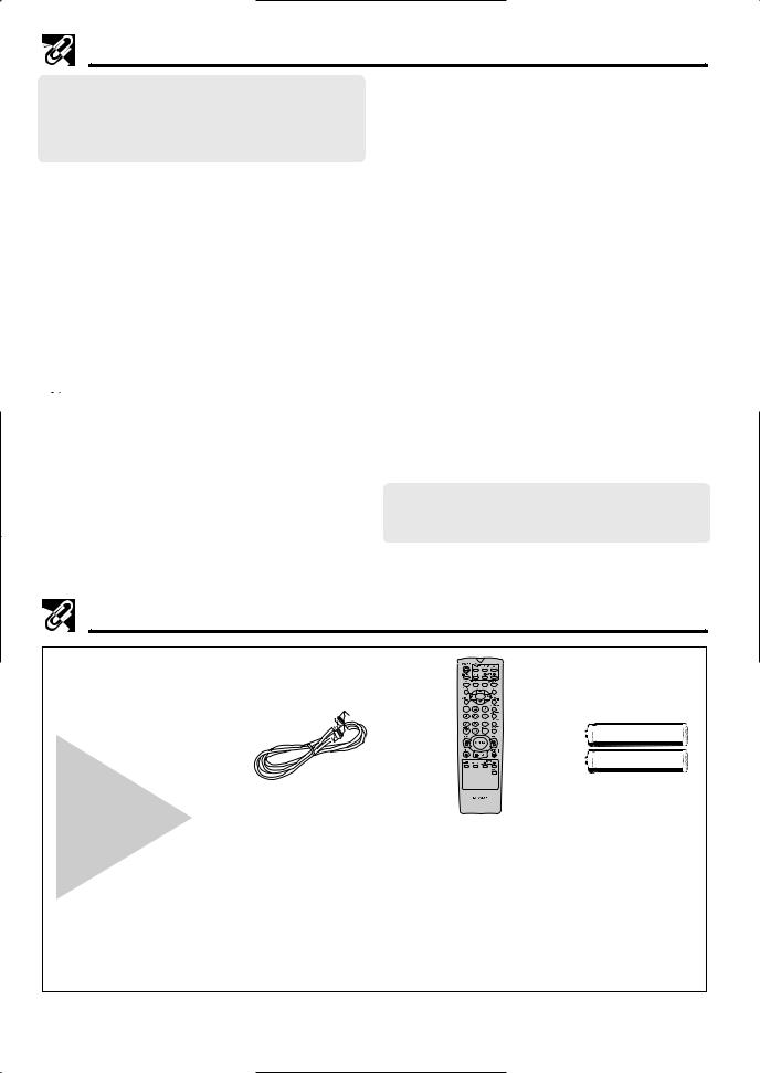
Accessories
Be sure that the following accessories are all included with your VCR.
VIDEO CASSETTE RECORDER
Round coaxial cable |
Remote control unit |
AA batteries for |
(75 Ohm, 1 m [3-1/4 ft.]) |
RRMCG1236AJSA |
the remote |
QCNW-8115AJZZ |
or |
control unit |
or |
RRMCG1236AJSB |
|
(75 Ohm, 0.9 m [3-11/18 ft.]) |
or |
|
QCNW-8530AJZZ |
RRMCG1236AJSC |
|
or |
|
|
QCNW-8533GEZZ |
|
|
or |
|
|
QCNW-8555AJZZ |
|
|
or |
|
|
QCNW-8614AJZZ |
|
|
6
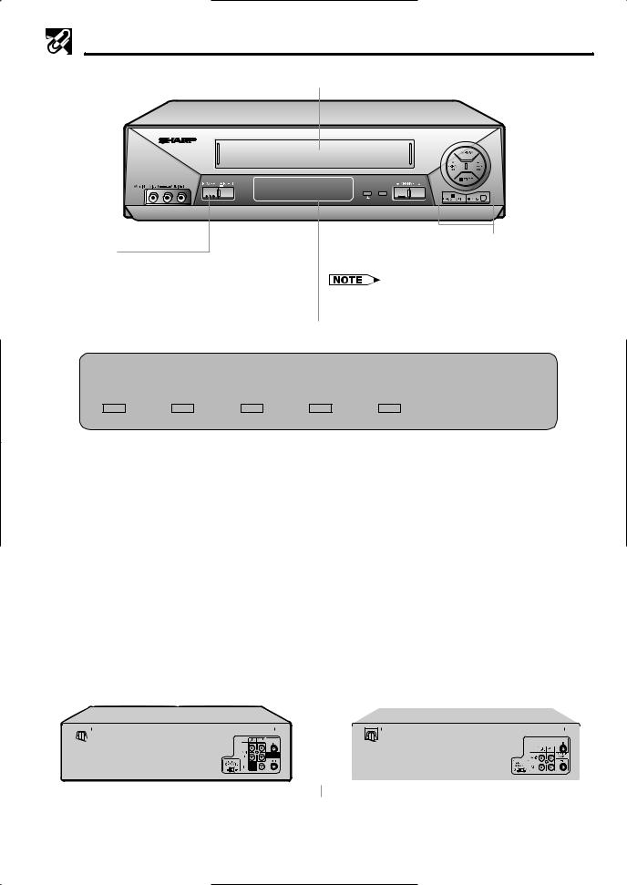
Major Components of Your VCR
[Front]
Cassette compartment (see Playback/Recording)
POWER TIMER VCR
(VC-H820U)
POWER button
(When pressed to turn on the VCR, POWER LED indicator will light up. When the power is turned off, POWER LED indicator will turn off.)
|
TAMPER REMOTE SENSOR |
|
REC |
PROOF |
SET MENU |
|
|
|
|
|
S.PICTURE |
Basic function controls (see Playback/Recording)
•The design may be slightly different depending on the model.
LED Indicator (explained throughout the operation instruction)
|
|
|
|
TAMPER |
REMOTE SENSOR |
POWER |
TIMER |
VCR |
REC |
PROOF |
|
|
|
|
|
|
|
|
|
|
|
|
|
! |
@ |
# |
$ |
% |
^ |
||||||
! POWER LED indicator |
|
|
|
|
|
|
$ REC LED indicator |
|
|
||
This indicator lights up whenever the VCR is turned on.
This indicator lights up during recording. This indicator flashes during REC-Pause.
@TIMER LED indicator
This indicator lights up when the VCR is set for timer recording, Simple Recording Timer and Recording with the Timer.
#VCR LED indicator
This indicator lights up when selecting “VCR” by using the TV/VCR button.
%TAMPER PROOF (ÿ) LED indicator
This indicator lights up when the set mode is locked.
^Remote Sensor
Point Remote Control at this window.
[Rear] |
|
|
|
|
|
|
|
|
|
|
|
|
||||||||||||||||
|
|
|
|
|
|
|
(VC-A410U, VC-A411U, VC-A420U) |
|||||||||||||||||||||
|
|
|
(VC-H810U, VC-H811U, VC-H820U) |
|
|
|
||||||||||||||||||||||
|
|
|
|
|
||||||||||||||||||||||||
|
|
|
|
|
|
|||||||||||||||||||||||
|
|
|
Connection terminals (see Connecting the VCR and |
|
|
|
Connection terminals (see Connecting the VCR and |
|||||||||||||||||||||
|
|
|
|
|
||||||||||||||||||||||||
|
|
|
|
|
|
|||||||||||||||||||||||
|
|
|
|
|
|
Cable TV Connections) |
|
|
|
|
|
Cable TV Connections) |
||||||||||||||||
|
|
|
|
|
|
|
|
|
|
|||||||||||||||||||
|
|
|
|
|
Connection terminals (see Tape Dubbing) |
|
|
|
|
|
Connection terminals (see Tape Dubbing) |
|
||||||||||||||||
|
|
|
|
|
|
|
|
|||||||||||||||||||||
|
|
|
|
|
|
|
|
|
||||||||||||||||||||
|
|
|
|
|
|
|
|
|
|
|
|
|
|
|
|
|
|
|
|
|
|
|
|
|
|
|
|
|
|
|
|
|
|
|
|
|
|
|
|
|
|
|
|
|
|
|
|
|
|
|
|
|
|
|
|
|
|
|
|
|
|
|
|
|
|
|
|
|
|
|
|
|
|
|
|
|
|
|
|
|
|
|
|
|
|
|
|
|
|
|
|
|
|
|
|
|
|
|
|
|
|
|
|
|
|
|
|
|
|
|
|
|
|
|
|
|
|
|
|
|
|
|
|
|
|
|
|
|
|
|
|
|
|
|
|
|
|
|
|
|
|
|
|
|
|
|
|
|
|
|
|
|
|
|
|
|
|
|
|
|
|
|
|
|
|
|
|
|
|
|
|
|
|
|
|
|
|
|
|
|
|
|
|
|
|
|
|
|
|
|
|
|
|
|
|
|
|
|
|
|
|
|
|
|
|
|
|
|
|
|
|
|
|
|
|
|
|
|
|
|
|
|
|
|
|
|
|
|
|
|
|
|
|
|
|
|
|
|
|
|
|
|
|
|
|
|
|
|
|
|
|
|
|
|
|
|
|
|
|
|
|
|
|
|
|
|
|
|
|
|
|
|
|
|
|
|
|
|
|
|
|
|
|
|
|
|
|
|
|
|
|
|
|
|
|
|
|
|
|
|
|
|
|
|
|
|
|
|
|
|
|
|
|
|
|
|
|
|
|
|
|
|
|
|
|
|
|
|
|
|
|
|
|
|
|
|
|
|
|
|
|
|
|
|
|
|
|
3 ↔ 4 OUTPUT CHANNEL selector |
3 ↔ 4 OUTPUT CHANNEL selector |
(see Setting the 3 ↔ 4 Output Channel Selector) |
(see Setting the 3 ↔ 4 Output Channel Selector) |
7
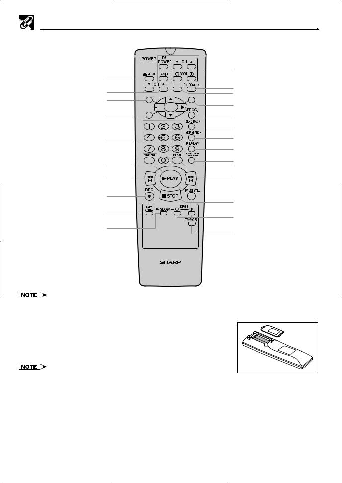
Remote Control
POWER button (p. 16) 

EJECT button (p. 22)
CH (CHANNEL) ∂/ƒ buttons (p. 28) 
 MENU button (p. 14)
∂/ƒ/ß/© button (p. 16) 
 CANCEL button (p. 31)
Numbered buttons (p. 18)
100/AM/PM button (p. 18) 
 PLAY button (p. 22)

REW button (p. 23)
REC button (p. 25)
TAPE SPEED button (p. 25)
SLOW button (p. 23)
TV Functions Control buttons (POWER, CH ∂/ƒ, VOL j/k and TV/VIDEO)
•This Remote Control can control many of SHARP’s TVs.
ON SCREEN button (p. 14)  (*)
(*)
SET button (p. 16)
PROG. (PROGRAM) button (p. 29)
ZERO BACK button (p. 32)
SKIP SEARCH button (p. 33)
REPLAY button (p. 33)
TAMPER PROOF button (p. 34)  INPUT button (p. 27)
FF button (p. 23)


 PAUSE/STILL button (p. 23) STOP button (p. 22)
j/k buttons (SLOW j/k, DPSS j/k) (p. 33)
TV/VCR buttons (p. 16)
VIDEO CASSETTE RECORDER
*: This button cannot be used for this model.
Inserting the Batteries
Make sure that the batteries have been properly installed first. Fit two batteries type “AA”. If the remote control stops working, fit new batteries.
Ensure the batteries are fitted correctly, matching the polarities (j/k) indicated in the remote control.
•Do not subject the remote control to shock, water or excessive humidity.
•The remote control may not function if the VCR sensor is in direct sunlight or any other strong light.
•Incorrect use of batteries may cause them to leak or burst. Read the battery warnings and use the batteries properly.
•Do not mix old and new batteries, or mix brands in use.
•Remove the batteries if the remote control will not be operated for an extended period of time.
•If the remote control does not function properly when new batteries are installed, remove the batteries and keep pressing any button for 10 seconds before re-installing them.
8
Connecting the VCR
The connection method differs depending on the type of TV.
If you have cable TV (CATV), see Cable TV Connections.
RF Connection (for connection to a TV without AV terminals)
! Disconnect the TV antenna from the TV.
@ Connect the TV antenna cable to the ANTENNA IN terminal on the rear of the VCR.
# Connect the TV OUT terminal on the rear of the VCR with the antenna terminal on the TV using a coaxial cable. Select the TV channel 3 or 4 corresponding to the 3 ↔ 4 output channel selector of the VCR. (See
Setting the 3 ↔ 4 Output Channel Selector below.)
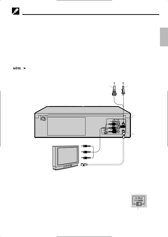
AV Connection (for connection to a TV with AV terminals)
! Disconnect the TV antenna from the TV.
@ Connect the antenna, VCR, and TV using the Audio/Video cable and coaxial cable (supplied) as shown.
# Select the video input mode or A/V input mode on your TV. (See the TV operation manual for details.)
Up Setting
• If your VCR is a monaural model, connect the audio cable to “AUDIO OUT” on the VCR.
Antenna
Connect the flat twin lead cable to a transformer (300 ohm to 75 ohm, not supplied)
VCR Rear (Hi-Fi model)
Audio/Video cable (not supplied)
TV
Coaxial cable (supplied)
Coaxial cable
ANTENNA IN (antenna or cable input)
TV OUT
After the Connection
Plug in the power cord of the TV. Then go to EZ Set Up.
Setting the 3 ↔ 4 Output Channel Selector
The 3 ↔ 4 OUTPUT CHANNEL selector changes the VCR OUTPUT to standard TV broadcasting signals. Both your TV and VCR must be set to the same channel (i.e. TV on channel 3 and VCR OUTPUT CHANNEL selector on 3).
Your VCR is set to channel 3 at the factory, so your TV should be tuned to channel 3 as well. If channel 3 is an active broadcast channel in your area, set the VCR 3 ↔ 4 OUTPUT CHANNEL selector to 4 and tune your TV to channel 4.
Rear of Your VCR
3 ↔ 4 OUTPUT CHANNEL selector
9
Cable TV Connections
Your VCR is capable of receiving the following non-scrambled channels.
• Scrambled channels can be received with the cable box supplied by your cable TV company.
Set the 3 ↔ 4 OUTPUT CHANNEL selector on the rear of the VCR to 3 or 4. (Factory preset: 3)
First check your TV/CATV system
Step Q Is your TV cable compatible with the VCR?
•YES → Go to Step W
•NO → Go to Step E
Step W Does your CATV system have some or all channels scrambled?
•YES |
→ |
Go to |
|
|
|||
•NO |
→ |
Go to |
|
|
Step E Does your CATV system have some or all channels scrambled?
•YES |
→ |
Go to |
|
|
|
||||
•NO |
→ |
Go to Step R |
||
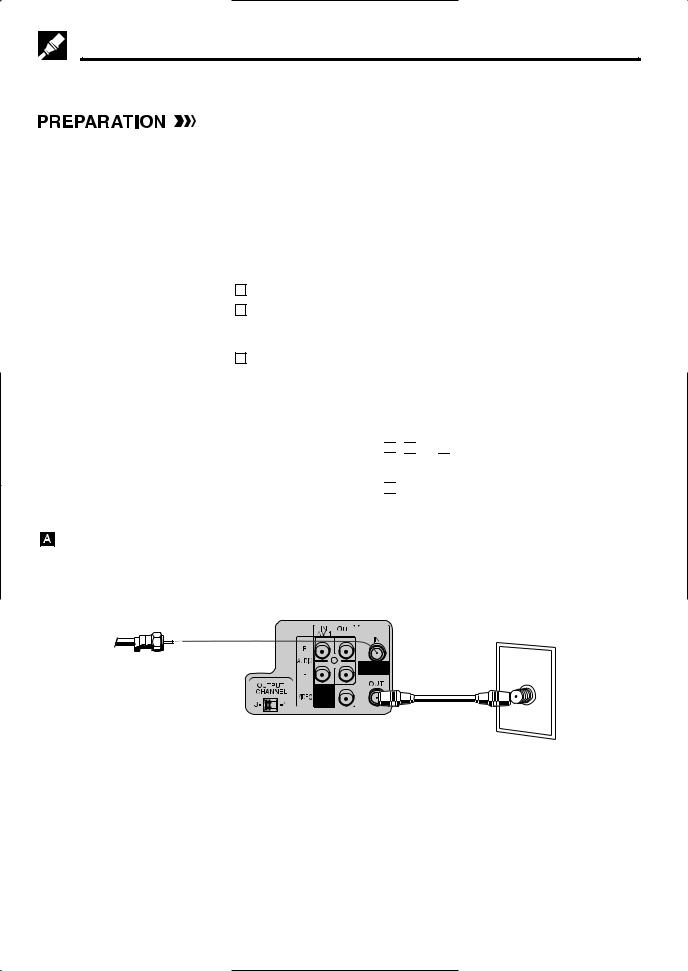
Step R Choose the type below.
•Basic connection (only for
descrambled CATV signals.) → Go to 

 -
- 

 or
or 
•To watch a CATV program while recording a TV program by using the A/B switch. → Go to 


Connection without a cable box
• Connect as shown. Then go to “After the Connection”.
VCR Rear (Hi-Fi model)
From CATV system
TV Rear
ANT/CABLE
Coaxial cable (Supplied)
10
Cable TV Connections
Connection with cable box
•Connect as shown. With this connection, it is possible to record descrambled CATV signals. Then go to “After the Connection”.
Cable Box |
Coaxial cable VCR Rear (Hi-Fi model) |
|
IN |
OUT |
(Not supplied) |
|
|
TV Rear |
From |
|
|
CATV |
|
ANT/CABLE |
system |
|
|
Coaxial cable (Supplied)
•If the cable box is turned off, it will not output any signals, thus making it impossible to record or view a program from the CATV system.
•In the case of the above connections, it is not possible to change channels using the VCR remote control. Only the cable box can be used to change channels.
•Only one channel at a time can be programmed for recording programs with the timer. It is not possible to watch a TV program different from the one being recorded.
•Depending on which terminals the TV has, a separate combiner (mixer) or separator (splitter) may be necessary.
•Connect as shown. With this connection, it is not possible to record CATV programs which have been scrambled, but is possible to record one channel and watch the other one. Then go to “After the Connection”.
From CATV system |
VCR Rear (Hi-Fi model) |
TV Rear |
|
||
|
Cable Box |
|
|
IN |
ANT/CABLE |
|
OUT |
|
Coaxial cable (Supplied)
Coaxial cable (Not supplied)
•With the above connection, ∂/ƒ of the VCR or the numbered buttons on the remote control can be used to select channels.
•Depending on which terminals the TV has, a combiner (mixer) or separator (splitter) may be necessary.
•To record one channel and watch another, the VCR must be set to the TV mode.
11
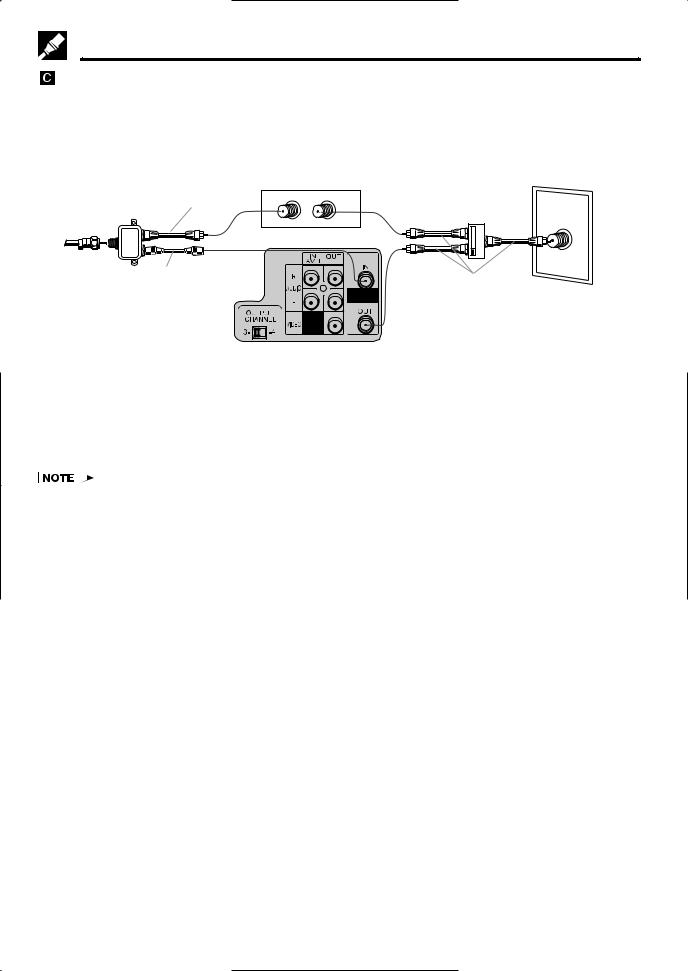
Cable TV Connections
Connection with cable box, A/B switch and splitter
By using an A/B switch or splitter, it is possible to switch between the cable box and the VCR output.
For example, while recording a TV program with the VCR, it is possible to watch a CATV program (including descrambled programs) using the A/B switch.
• Connect as shown. Then go to “After the Connection”.
|
Splitter |
Coaxial cable |
Cable Box |
|
From |
(Not supplied) |
IN |
OUT |
|
(Not supplied) |
|
|
||
|
|
|
||
CATV |
|
|
|
|
system |
VCR Rear (Hi-Fi model) |
|||
|
|
|||
|
Coaxial cable |
|
|
|
|
(Supplied) |
|
|
|
TV Rear
A/B switch |
|
(Not supplied) |
ANT/CABLE |
|
|
A |
|
B |
|
Coaxial cable |
|
(Not supplied) |
|
Using the A/B Switch
1.Set the A/B switch to the “A” position in the following situations.
! To watch a cable TV program while recording another program. @ To watch a scrambled cable TV program.
# To watch a cable TV program when the VCR is turned off.
•Use the cable box to change channels.
•If you turn off the cable box, you cannot watch a CATV program.
2.Set the A/B switch to the “B” position in the following situations.
! To play back a cassette on the VCR.
@ To watch a program which is being recorded with the VCR tuner.
# To watch a program using the VCR tuner.
12
 Loading...