

Page 1

SERVICE MANUAL
S13V5SX76NF8/
COLOUR TELEVISION
Chassis No. GA-20X
SX76NF8
MODEL
In the interests of user-safety (Required by safety regulations in some countries) the set should be restored
to its original condition and only parts identical to those specified should be used.
SX76NF8
FEATURE
Ë
Ë
Full Auto Channel Preset and Auto Channel Skip
Ë
100 CH Program Memory
Ë
CATV (Hyper Band) Ready
<Used Frequency Synthesizer Tuner>
Ë
High Contrast Picture
Ë
TELETEXT(10 page)
English / German / French / Spanish / Italian
/ Swedish / Dutch / portuguese
Ë
ON Timer/OFF T imer
Blue Back Noise Mute
Ë
White Temperature Adjustment
Ë
Child Lock
Ë
Auto Sound Limiter
Ë
Headphone Terminal
Ë
Stereo (NICAM / IGR) Decoder
Ë
Rotation adjustment (picture tilt adjustment)
Ë
Component Input Terminal
CONTENTS
Page
» SPECIFICATIONS.............................................2
» IMPORTANT SERVICE NOTES........................2
» ADJUSTMENT PRECAUTIONS........................3
» TROUBLE SHOOTING TABLE ......................... 8
» WAVEFORMS ..................................................12
» CHASSIS LAYOUT ..........................................14
» BLOCK DIAGRAM...........................................16
» DESCRIPTION OF SCHEMATIC DIAGRAM ..18
» SCHEMATIC DIAGRAM
Ë
CRT UNIT.....................................................19
Ë
MAIN UNIT ...................................................20
Ë
CONTROL UNIT .......................................... 26
Ë
DF UNIT .......................................................28
Ë
LED UNIT .....................................................29
Ë
KEY UNIT..................................................... 29
Ë
SUB WOOFER UNIT ...................................30
» PRINTED WIRING BOARD ASSEMBLIES..... 31
» REPLACEMENT PARTS LIST
Ë
ELECTRICAL PARTS
MAIN UNIT ................................................... 38
CRT UNIT.....................................................43
CONTROL UNIT .......................................... 44
DF UNIT .......................................................45
LED UNIT .....................................................45
SUB WOOFER UNIT ...................................45
KEY UNIT..................................................... 45
Ë
MISCELLANEOUS PARTS..........................46
Ë
SUPPLIED ACCESSORIES.........................46
Ë
PACKING PARTS......................................... 46
Ë
CABINET PARTS ......................................... 46
Ë
CABINET PARTS LOCATION...................... 46
» PACKING OF THE SET...................................47
Page
The chassis in this receiver is partially hot. Use an isolation transformer between the line cord plug and power
receptacle, when servicing this chassis. To prevent electric shock, do not remove cover. No user – serviceable
parts inside. Refer servicing to qualified service personnel.
WARNING
SHARP CORPORATION
1
Page 2
SX76NF8
SPECIFICATIONS
Convergence ................................................................. Self Convergence System
Focus ............................................................Electrostatic Focus High Bi-Potential
Sweep Deflection......................................................................................Magnetic
Intermediate Frequencies
Picture IF Carrier .................................................................................. 38.9MHz
Sound IF Carrier Frequency
5.5MHz ..............................................................................................33.4MHz
Colour Sub-Carrier Frequency............................................................34.47MHz
Power Input......................................................................... AC 220 ~ 240V 50 Hz
Power Consumption ...................................................................................... 140W
Audio Power Output Rating ............................................5W + 5W + 10W(at Max.)
Speaker
Size.............................................................................. 11 x 5 cm Elliptic (2 pcs)
10cm Round (1pc)
Voice Coil Impedance..............................................................4 ohm (11 x 5cm)
8 ohm (10cm)
Aerial Input Impedance
VHF/UHF ............................................................................ 75 ohm Unbalanced
Receiving System (PAL-B/G)
VHF.......................................................................................AU 0 thru AU 12 ch
UHF ....................................................................................AU 28 thru AU 69 ch
Receiving Frequency
VHF-Channels ......................................................... 44.25MHz thru 463.25MHz
UHF-Channels....................................................... 471.25MHz thru 863.25MHz
Dimensions................................................................................... Width: 880.0mm
Height: 566.0mm
Depth: 545.0mm
Weight(approx): 54.0 kg
Cabinet material .................................................................................... All Plastics
Specifications are subject to change without prior notice.
IMPORTANT SERVICE NOTES
Maintenance and repairing of this receiver should be done by quali-
fied service personnel only .
SERVICE OF HIGH VOLTAGE SYSTEM AND PIC-
TURE TUBE
When servicing the high voltage system, remove static charge from it by
Connecting a 10K ohm Resistor in series with an insulated wire(such as a
test probe) between picture tube dag and 2nd anode lead. (AC line cord
should be disconnected from AC outlet.)
1. Picture tube in this receiver employs integral implosion protection.
2. Replace with tube of the same type number for continued safety.
3. Do not lift picture tube by the neck.
4. Handle the picture tube only when wearing shatterproof goggles and after discharging
the high voltage completely.
X-RAY
This receiver is designed so that any X-Ray radiation is kept to an absolute
Minimum. Since certain malfunctions or servicing may produce potentially
hazardous radiation with prolonged exposure at close range, the following
precautions should be observed:
1. When repairing the circuit, be sure not to increase the high voltage to more than 34.5kV(at
beam 0
µ
A) for the set.
2. To keep the set in a normal opeartion , be sure to make it function on 30.5kV
±
1.5kV(at
beam 1800
µ
A) in the case of the set. The set has been factory - Adjusted to the above-
mentioned high voltage.
*If there is a possibility that the high voltage fluctuates as a result of the repairing,
never forget to check for such high voltage after the work.
3. Do not substitute a picture tube with unauthorizerd types and/or brands which may
cause excess X-ray radiation.
BEFORE RETURNING THE RECEIVER
Before returning the receiver to the user, perform the following safety Checks.
1. Inspect all lead dress to make certain that leads are not pinched or that hardware is not
lodged between the chassis and other metal parts in the receiver.
2. Inspect all protective devices such as non-metallic control knobs, insulating fishpapers,
cabinet backs, adjustment and compartment covers or shields, isolation resistor- ca-
pacity networks, mechanical insulators etc.
2-2
2-1
2
Page 3
SX76NF8
ADJUSTMENT PRECAUTIONS
All adjustments to this chassis, except for focus, are carried out in the Service Mode.
Service Mode
The Service Mode is provided to enable the engineer to correctly set up the receiver to the CRT fitted in the set.
Note that these adjustments may vary from one receiver to another.
To enter the Service Mode, carry out the following procedure.
1.Connect a test pattern to the antenna terminal.
2.Tune the receiver to this signal.
3.Turn the receiver off using the mains switch.
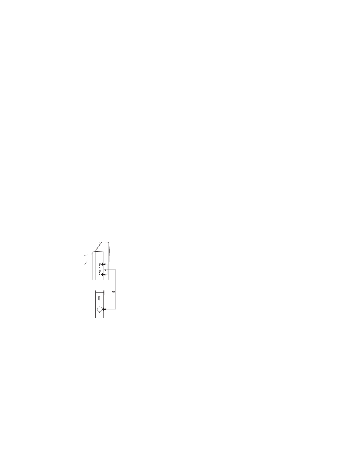
4.Press volume down and channel up buttons on the front of
the receiver at the same time.
5.Keeping these buttons pressed, turn the mains on.
6.When the set starts up it will be in Service Mode.
7.Release the two buttons.
» Use the channel up and down buttons to move between the options.
» Use the volume control buttons to change the data.
» To store the data, use the stand-by button on the remote control.
» To exit the Service Mode, turn the receiver off using the mains switch.
When the Service Mode is entered the following On Screen Display appears
SERVICE SOFTWARE
SW on: XXXX SW off: XXXX Hours ON: XXXX
The figures displayed in the XXXX locations are hexadecimal representations of the number of times that particular
function has been executed. For example if the hexadecimal number displayed after SW ON was 0E4A, this would
correspond to the receiver being turned on 3658 times.
Adjustment menu:
The following adjustments can be carried out in the Service Mode.
» Horizontal Shift » Blue Gain
» East West Width » Red Cut Off
» Pin Phase » Green Cut Off
» Pin Amp (Amplitude) » Blue Cut Off
» Corner Amplitude » Alter NVM Pag (Page)
» Corner Symmetry » Alter NVM Pos (Position)
» Vertical Linearity » Alter NVM Val (Value)
» Vertical Angle » Teletext Mix Mode Contrast
» Vertical Bow » Teletext Contrast
» Vertical Amplitude » OSD Contrast
» S Correction » DVCO Adjustment (Only PAL)
» Vertical Shift » DVCO Adjustment (Only NTSC)
» Red Gain » AGC Adjustment
» Green Gain » Rotation Inspection
» INTIAL On/Off
Note that the receiver should be set to FULL MODE before carrying out any geometry adjustments. This can be achieved
by pressing the widescreen mode button on the remote control until FULL MODE appears on the OSD. This can only be
done out of the Service Mode.
Detailed instructions on how to execute these are given on the following pages.
Front
Top of front cabinet
Changing NVM Data
To change the data contained within the Non Volatile Memory, it is necessary to first select the page the data is stored
in, then the position and finally to change the data itself. The procedure below outline this process.
1. Press the channel up/down buttons and ALTER NVM PAG appears, use the volume up/down buttons to change this
data (it is shown in hexadecimal format).
2. Press the channel up button and ALTER NVM POS appears use the volume up/down buttons to change this data (it
is shown in hexadecimal format).
3. Press the channel up button and ALTER NVM VAL appears, use the volume up/down buttons to change this data (it
is shown in hexadecimal format).
4. Once this data has been set, press the stand-by button to store.
5. If another NVM value has to be changed, use the channel down button to select the page or position and repeat as
necessary.
Note: DO NOT change any NVM data, unless you have been adviced to do so by a Sharp representative. If data is
incorrectly changed, serious damage may occur to hte receiver.
3-2
3
3-1
Page 4
SX76NF8
PIF ADJUSTMENT
NO
1
ADJUSTMENT POINT
RF-AGC
ADJUSTMENT
(I2C BUS CONTROL)
ADJUSTMENT CONDITION / PROCEDURE
(1) Receive signal.
E-12cH
Signal strength: 57
± 1dBµV (50 ohm open)
(2) Call "AGC" mode in service mode.
(3) Push "power button", automatically adjust.
WAVEFORM OR OTHERS
Note: For the 50 ohm signal strength gauge,
when not using 50/75 impedance adapter,
signal strength is 57
±1dBµV(50 ohm open),
instead of 59 ±1dBµV(75 ohm open).
precaution: The loss of using impedance
adapter.
CUT OFF, BKGD ADJUSTMENT
NO
1
ADJUSTMENT POINT
AGING
ADJUSTMENT CONDITION / PROCEDURE
(1) Receive PR-99ch (BLUE BACK OFF), "NOISE
PICTURE"
(2) Aging 30 minutes.
WAVEFORM OR OTHERS
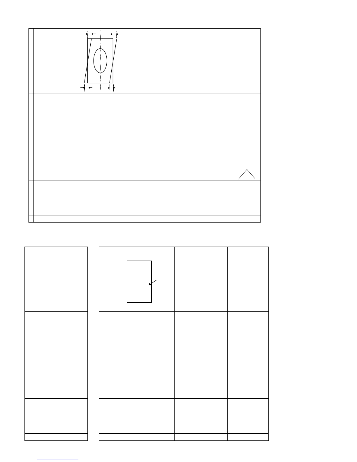
1 CRT CUTOFF
ADJUSTMENT
(1) Receive 50Hz Monoscope Pattern Signal.
(2) Set Picture Normal condition.
(3) Select full mode.
(4) Call "RED GAIN" mode in service mode.
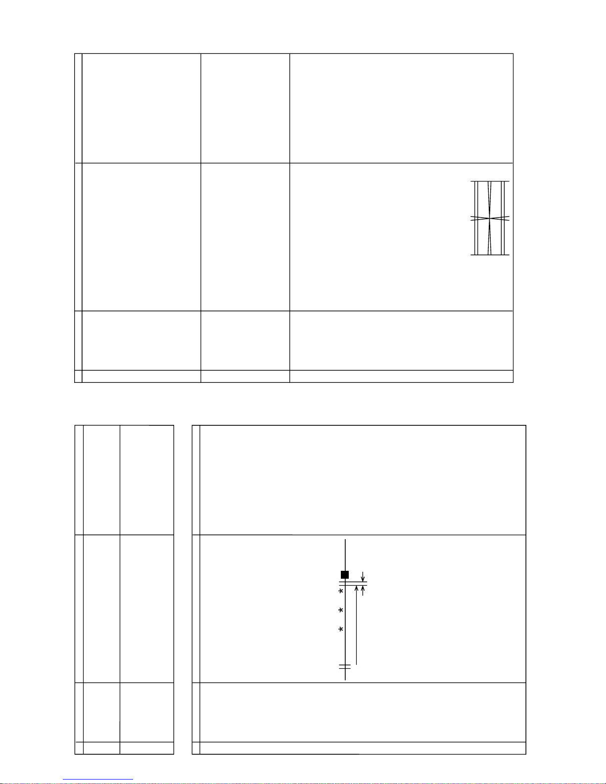
(5) Adjust SCREEN VR, so that the value of OSD reach
50h ± 8h. (Fig.1)
07 52 53 54
13 50 51 52
Fig.1
The value of this point
2
WHITE BALANCE
SERVICE MODE ADJ
(1) Receive the "WHITE/BLACK" Pattern SIGNAL.
(2) Press R/C to set Picture NORMAL condition.
(3) Select full mode.
(4) Call "*** GAIN/***CUT OFF" mode in service mode.
(5) Adjust the "RED GAIN","GREEN GAIN","BLUE
GAIN","GREEN CUT OFF", and "BLUE CUT OFF" data
to have a colour temperature of 12300
°K (white).
3
Max Beam Check (1) Receive 50Hz Monoscope Pattern Signal.
(2) Press R/C to set Picture NORMAL condition.
(3) Select full mode.
(4) Connect the DC miliammeter between R611(10K
Ω)
(Full Scale: 3mA Range)
(5) Beam current must be within 1600
±100µA.
Refer to SHIPPING SETTING & CHECKING.
• 12300°KX : 0.272±0.010
Y : 0.275±0.010
(MINOLTA COLOUR ANALYZER CA-100)
*Note: Above Data can be UP/DOWN by
Volume Key.
HIGH 100cd/m
2
± 10cd/m
2
LOW 10.0cd/m
2
± 1cd/m
2
HORIZONTAL, VERTICAL, DEFLECTION LOOP ADJUSTMENT.
NO
1
2
3
4
5
6
7
8
9
10
11
12
ADJUSTMENT POINT
1) 50Hz FULL
V. LINEARITY
(I2C BUS CONTROL)
VERTICAL SHIFT
(I2C BUS CONTROL)
VERTICAL AMP.
(I2C BUS CONTROL)
HORIZONTAL SHIFT
(I2C BUS CONTROL)
EAST -W AST WIDTH
(I2C BUS CONTROL)
PIN PHASE
(I2C BUS CONTROL)
PIN AMP
(I2C BUS CONTROL)
CORNER AMPLITUDE
(I2C BUS CONTROL)
CORNER SYMMETRY
(I2C BUS CONTROL)
VERTICAL ANGLE
(I2C BUS CONTROL)
VERTICAL BOW
(I2C BUS CONTROL)
S CORRECTION
(I2C BUS CONTROL)
2) 50Hz CINEMA
3) 60Hz FULL
4) 60Hz CINEMA
ADJUSTMENT CONDITION / PROCEDURE
(1) Press R/C to set Picture NORMAL condition.
(2) Select full mode.
*Receive 50Hz Monoscope Pattern Signal.
(1) Call the "VERTICAL LINEARITY" mode.
(2) Increase or decrease "VERTICAL LINEARITY" by
Volume key till the horizontal line in the center of
monoscope is just at the position where the blanking
starts.
(1) Call the "VERTICAL SHIFT" mode.
(2) Increase or decrease "VERTICAL SHIFT" by Volume key
till the picture is centered.
(1) Call the "VERTICAL AMPLITUDE" mode.
(2) Increase or decrease "VERTICAL AMPLITUDE" by
Volume key to set overscan of 8% typical.
Adjustment Spec 8% range +1% -1%
(1) Call the "H-CENT" mode.
(2) Increase or decrease "H-CENT" by Volume Key to center
the picture horizontal.
(1) Call the "EAST-WAST WIDTH" mode.
(2) Increase or decrease "EAST-WAST WIDTH" by Volume
key to set overscan of 8% typical.
Adjustment Sepc 8% range +1% -1%
*Receive 50Hz Cross-Hatch Pattern Signal.
(1) Call the "PIN PHASE" mode.
(2) Increase or decrease "PIN PHASE" by Volume key.
(1) Call the "PIN AMP" mode.
(2) Increase or decrease "H-CENT" by Volume key.
(1) Call the "CORNER AMPLITUDE" mode.
(2) Increase or decrease "CORNER AMPLITUDE" by
Volume key.
(1) Call the "CORNER SYMMETRY" mode.
(2) Increase or decrease "CORNER SYMMETRY" by
Volume key.
(1) Call the "VERTICAL ANGLE" mode.
(2) Increase or decrease "VERTICAL ANGLE" by Volume
key.
(1) Call the "VERTICAL BOW" mode.
(2) Increase or decrease "VERTICAL BOW" by Volume key.
(1) Call the "S CORRECTION" mode.
(2) Increase or decrease "S CORRECTION" by Volume key.
Adjust items NO1---NO12, same as 50Hz FULL
In CINEMA mode
V-SIZE Adjustment Spec 25% range +1% -0%
H-SIZE Adjustment Spec 8% range +1% -1%
WAVEFORM OR OTHERS
Note:
V. LINEARITY is the fixation values.
No adjustment.
VERTICAL SHIFT and VERTICAL AMP.
2mm > |A-B| E-5
2mm > |C-D| A face is for south
Adjustment Spec 8.0% range +1% -1%
at the upper side of the geometry center and
the lower side of the geometry center
CORNER SYMMETRY is the fixation values.
No adjustment
VERTICAL ANGLE is the fixation values.
No adjustment
VERTICAL BOW is the fixation values.
No adjustment
Note: Refer to PAGE 9/11
A
B
C
D
4-2
4-1
4
Page 5
SX76NF8
FOCUS ADJUSTMENT
NO
1
ADJUSTMENT POINT
FOCUS
ADJUSTMENT CONDITION / PROCEDURE
(1) Receive the "Monoscope Pattern" signal.
(2) Press R/C to set Picture NORMAL condition.
(3) Select full mode.
(4) Adjust the focus control to get the best focusing.
(Refer to Adjustment Point as right drawing, SX76NF8
and SX66NF8)
WAVEFORM OR OTHERS
(Adjusted point)
PROTECTOR OPERATION CHECKING
NO
1
2
ADJUSTMENT POINT
H•V PROTECTOR
OTHER
PROTECTOR
ADJUSTMENT CONDITION / PROCEDURE
(1) Receive "Monoscope Pattern" signal.
(2) Connect output of Bias Box to D607 cathode
(3) Set voltage of Bias Box to 18V and make sure the
protector is not work.
(4) Set voltage of Bias Box to 27V, and make sure the
protector is work.
(1) Once finish rectified Electrolytic Capacitor short testing
in + B line, check all possible damaged components on
+B line.
(Use random selected set for inspection)
WAVEFORM OR OTHERS
A/V INPUT AND OUTPUT CHECKING
NO
1
2
3
4
5
6
ADJUSTMENT POINT
AV
OUTPUT CHECK
AV-1
INPUT CHECK
AV-2
INPUT CHECK
AV-1
Component
INPUT CHECK
FRONT
INPUT CHECK
FRONT S-Terminal
INPUT CHECK
ADJUSTMENT CONDITION / PROCEDURE
(1) Receive the "PAL Color Bar" signal (100% White Color
Bar, Sound 400Hz 100% Mod)
(2) Terminate the Video output with a 75 ohm impedance.
Make sure the output is as specified (1.0 Vp-p
± 3dB)
(3) Terminate the Audio output with a 10 Kohm impedance.
Make sure the output is as specified (2.61 Vp-p
± 3dB)
Check of AV
Check of AV
Check of AV
Check of AV
Check of AV
WAVEFORM OR OTHERS
50
Adjust these Horizontal
and Vertical lines
(SX76NF8)
Adjust at "50" position
(SX66NF8)
FUNCTION OPERATION CHECKING (1) (VIDEO & AUDIO)
NO
1
2
3
4
5
6
7
8
9
ADJUSTMENT POINT
CONTRAST
COLOUR
BRIGHTNESS
SHARPNESS
TINT
ECO MODE
COMB FILTER
NTSC HUE
NORMAL
ADJUSTMENT CONDITION / PROCEDURE
(1) Receive "Monoscope Pattern" signal.
(2) Set P-Mode to select CONTRAST.
(3) Press Volume Up/Down key to check whether the
CONTRAST effect is OK or not.
(1) Receive "Color Bar" signal.
(2) Set P-Mode to select COLOUR.
(3) Press Volume Up/Down key to check whether the
COLOUR effect is OK or not.
(1) Receive "Monospcope Pattern" signal.
(2) Set P-Mode to select BRIGHTNESS.
(3) Press Volume Up/Down key to check whether the
BRIGHTNESS effect is OK or not.
(1) Receive "Monoscope Pattern" signal.
(2) Set P-Mode to select SHARPNESS.
(3) Press Volume Up/ Down key to check whether the
SHARPNESS effect is OK or not.
(1) Receive "Monoscope Pattern" signal.
(2) Set PICTURE to TINT select.
(3) Press Volume Up/Down key to check TINT Option,
STANDARD: NORMAL SETTING, WARM for more
REDDISH direction changing, COOL for more BLUISH
direction changing.
(1) Receive "Monoscope Pattern" signal.
(2) Set P-Mode to select ECO MODE.
(3) Press Volume Up/Down key to check whether the ECO
MODE effect is OK or not.
(1) Receive "Color Bar" signal.
(2) Set P-Mode to select COMB FILTER.
(3) Press Volume Up/Down key to check whether the COMB
FILTER effect is OK or not.
(1) INPUT "NTSC Color Bar" signal from AV-input.
(2) Set P-Mode to select NTSC HUE..
(3) Press Volume Up/Down key to check whether the NTSC
HUE effect is OK or not.
(1) In PICTURE Mode, select NORMAL and press menu
button all the settings will be present to normal setting.
(Normal setting value for every mode).
CONTRAST : 80%
COLOUR : 50%
BRIGHTNESS : 50%
SHARPNESS : 50%
TINT : 50%
WAVEFORM OR OTHERS
Notes:
If nothing is display mean contrast, colour,
bright, tint, sharpness are all normal setting.
5-2
5
5-1
Page 6
SX76NF8
CHECKING FUNCTION OPERATION (2) (VIDEO & AUDIO) CONTINUED
NO
10
11
12
13
14
15
ADJUSTMENT POINT
VOLUME
BALANCE
BASS
TREBLE
SOUND IDENT
DYNAMIC BASS
ADJUSTMENT CONDITION / PROCEDURE
(1) Receive "Monoscope Pattern" signal.
(2) Set S-Mode to select VOLUME.
(3) Press Volume Up/Down key to check whether the
VOLUME effect is OK or not.
(1) Receive "Monoscope Pattern" signal.
(2) Set S-Mode to select BALANCE.
(3) Press Volume Up/Down key to check whether the Left-to
-Right BALANCE effect is OK or not.
(1) Receive "Monoscope Pattern" signal.
(2) Set S-Mode to select BASS.
(3) Press Volume Up/Down key to check whether the BASS
effect is OK or not.
(1) Receive "Monoscope Pattern" signal.
(2) Set S-Mode to select TREBLE.
(3) Press Volume Up/ Down key to check whether the
TREBLE effect is OK or not.
(1) Receive "Monoscope Pattern" signal.
(2) Set S-Mode to select SOUND IDENT.
(3) Press Volume Up/Down key to check whether the
SOUND IDENT effect is OK or not.
(1) Receive "Monoscope Pattern" signal.
(2) Set S-Mode to select DYNAMIC BASS.
(3) Press Volume Up/Down key to check whether the
DYNAMIC BASS effect is OK or not.
WAVEFORM OR OTHERS
CHECKING FUNCTION OPERATION (3) (VIDEO & AUDIO) CONTINUED
NO
16
17
18
19
ADJUSTMENT POINT
VOLUME
Headphone
BALANCE
Headphone
BASS
Headphone
TREBLE
Headphone
ADJUSTMENT CONDITION / PROCEDURE
(1) Connect Headphone
(2) Set S-Mode to select VOLUME in headphone mode.
(3) Press Volume Up/Down key to check whether the
VOLUME effect is OK or not.
(1) Connect Headphone.
(2) Set S-Mode to select BALANCE in headphone mode.
(3) Press Volume Up/Down key to check whether the Left-to
-Right BALANCE effect is OK or not.
(1) Connect Headphone.
(2) Set S-Mode to select BASS in headphone mode.
(3) Press Volume Up/Down key to check whether the BASS
effect is OK or not.
(1) connect Headphone.
(2) Set S-Mode to select TREBLE in headphone mode.
(3) Press Volume Up/ Down key to check whether the
TREBLE effect is OK or not.
WAVEFORM OR OTHERS
CHECKING FUNCTION OPERATION (WIDE MODE)
NO
1
2
3
ADJUSTMENT POINT
WIDE MODE
V-SIZE
in wide mode
V-SCROLL
in wide mode
ADJUSTMENT CONDITION / PROCEDURE
(1) Receive "Monoscope Pattern" signal.
(2) Press WIDE key to check change WIDE mode
AUTO/PANORAMA/FULL/NORMAL/ZOOM14:9/CINEMA
(1) Receive "Monoscope Pattern" signal.
(2) Select PANORAMA, ZOOM14:9, and CINEMA mode.
(3) Select V-SIZE, Press Volume Up/Down key to check
whether the V-SIZE effect is OK or not.
(1) Receive "Monoscope Pattern" signal.
(2) Select PANORAMA, ZOOM14:9, and CINEMA mode.
(3) Select V-SCROLL, Press Volume Up/Down key to check
whether the V-SCROLL effect is OK or not.
WAVEFORM OR OTHERS
6-2
6
6-1
Page 7
SX76NF8
CHECKING FUNCTION OPERATION (TEXT MODE)
NO
1
2
ADJUSTMENT POINT
TEXT
TEXT key
ADJUSTMENT CONDITION / PROCEDURE
(1) Receive E-12ch signal.
(2) Press TEXT key to check change TEXT mode /
SPLIT SCREEN mode / TELETEXT mode / MIXED
mode.
(1) Receive E-12ch signal.
(2) Press HALF PAGE, HOLD, REVEAL, CLOCK, CANCEL,
LIST, INDEX, and RESET key to check whether each
effect is OK or not.
(3) Select V-SIZE, Press Volume Up/Down key to check
whether the V-SIZE effect is OK or not.
WAVEFORM OR OTHERS
PURITY AND CONVERGENCE ADJUSTMENT
NO
1
ADJUSTMENT POINT
DY location (YPB)
adjustment procedure
ADJUSTMENT CONDITION / PROCEDURE
(1) Turn on the set to make coarse adjustments to the CRT
cut-off, white balance, etc. as well as the purity static
convergence.
(2) To improve the purity adjustment accuracy, perform
coarse adjustments to the H-SIZE/center, V-SIZE/LIN
and side pin.
(3) Enter the video mode to set the beam current to the
standard value below using the screen VR. (Or it is
possible to use the noise signal of an empty channel.)
Age the set for more than 30 minutes with the following
current.
Standard value of beam current: 1000
µA ± 200µA
(4) Receive the monoscope signal to adjust the cut-off
voltage.
Consequently, adjust the contrast, color level and then
set the beam current to the above standard value.
Age the set for more than 2 minutes.
Note: If other adjustments between step 3 and 4 (the
area marked by *) affect the conditions of the beam
current, complete the adjustment for each point within 2
minutes, which is not included in the aging time).
* Perform the adjustments in an earth magnetism room
with Bh and Bv set to 0.20G and -0.50G respectively.
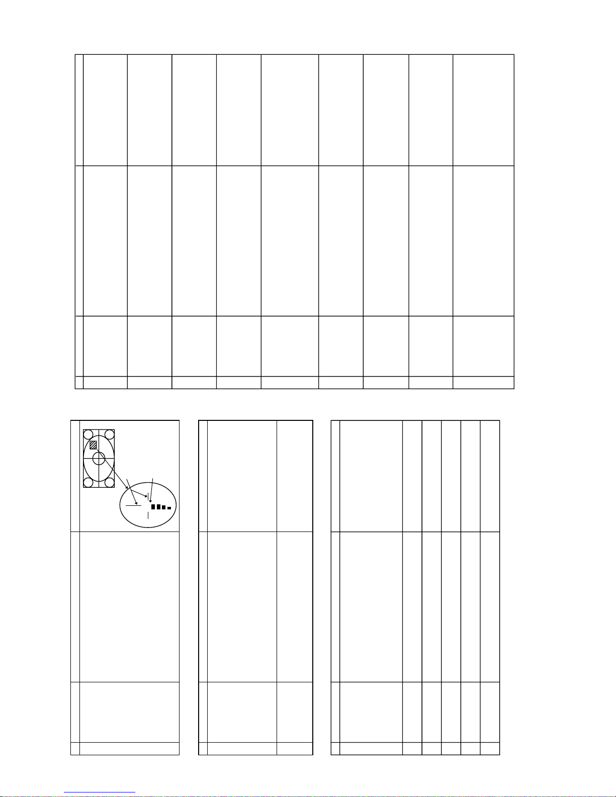
(5) Under the above conditions, move DY and the purity
magnet to make the following adjustments.
- 1. Set YPB of DY to 2.5 mm temporarily.
- 2. Adjust the center to A rank by moving the purity
magnet.
- 3. Insert a temporary wedge to balance DY vertically.
- 4. Move DY back and forth to set L and R to the
standard value below. (Apply to the purity correction
magnet if L and R are imbalanced.)
- 5. Correct the center to "AB rank" if the L and R are
imbalanced.
- 6. After making sure the landing is properly positioned,
fix DY.
Note: Preliminary adjustments are made to set L and R
to the standard value after convergence adjustment.
Standard value: -25
µm ± 5 µm at the 90 mm point
WAVEFORM OR OTHERS
Purity adjustment
Aging for more
than 2 minutes
Aging for more than 30 minutes
Raster
output
PURITY AND CONVERGENCE ADJUSTMENT (Continued)
NO
2
ADJUSTMENT POINT
Peripheral landing
correction
ADJUSTMENT CONDITION / PROCEDURE
(1) Place the set in a magnetic room with the horizontal line
and vertical line set to 0G and - 0.5G respectively, and
receive red monochrome.
(2) After a complete external; demagnetization, generate a
horizontal magnetic field of
±10000nT (0.1G) and apply
the purity correction magnet to the multi-colored areas.
Check blue monochrome equally.
(3) Return the magnetic field to zero and perform a
complete demagnetization.
(4) Generate a reverse horizontal magnetic field, check red
and blue monochrome and apply the magnet to multi-
colored areas.
(5) After correcting the magnet in step 4, check the reverse
magnetic field again.
3 Directional tolerance
check
(1) Place the set in a magnetic room the horizontal line and
vertical line set to 0.2G and - 0.5G respectively, and
receive red monochrome.
(2) Move the set from side to side at the four points of the
compass to check the status of the multiple colors and
ensure L and R are well-balanced.
(3) Apply to the purity correction magnet if L and R are
imbalanced.
(4) If the magnet was applied in step 3, check from other
directions equally.
WAVEFORM OR OTHERS
4 Convergence
adjustment procedure
(1) Set the video adjustment level to normal, and receive a
crosshatch pattern.
(2) Center convergence adjustment
Superimpose RGB of the screen center area for
optimization, by using the 4 pole and 6 pole of the purity
magnet. Superimpose the red and blue by the 4 pole
magnet, the green and magenta by the 6 pole magnet.
As for vertical lines, avoid setting the red line to the left,
blue to the right.
(3) Peripheral convergence adjustment
Combine the following item with the ferrite sheet to make
optimal adjustments.
1.XV cross
Rotate the variable coil on the DY PWB for
optimization.
2.YH cross
Adjust with the volume on the DY PWB.
If peripheral PQH is oversized, correct with the ferrite
sheet or by shaking slightly.
3.XH, YV
Use the dedicated correction strip to correct them.
YH
YV
XV
7-2
7
7-1
Page 8
SX76NF8
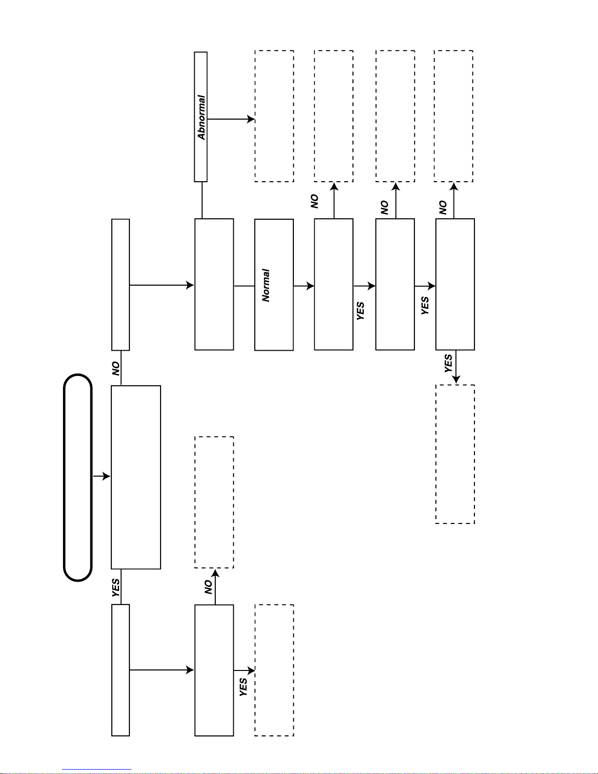
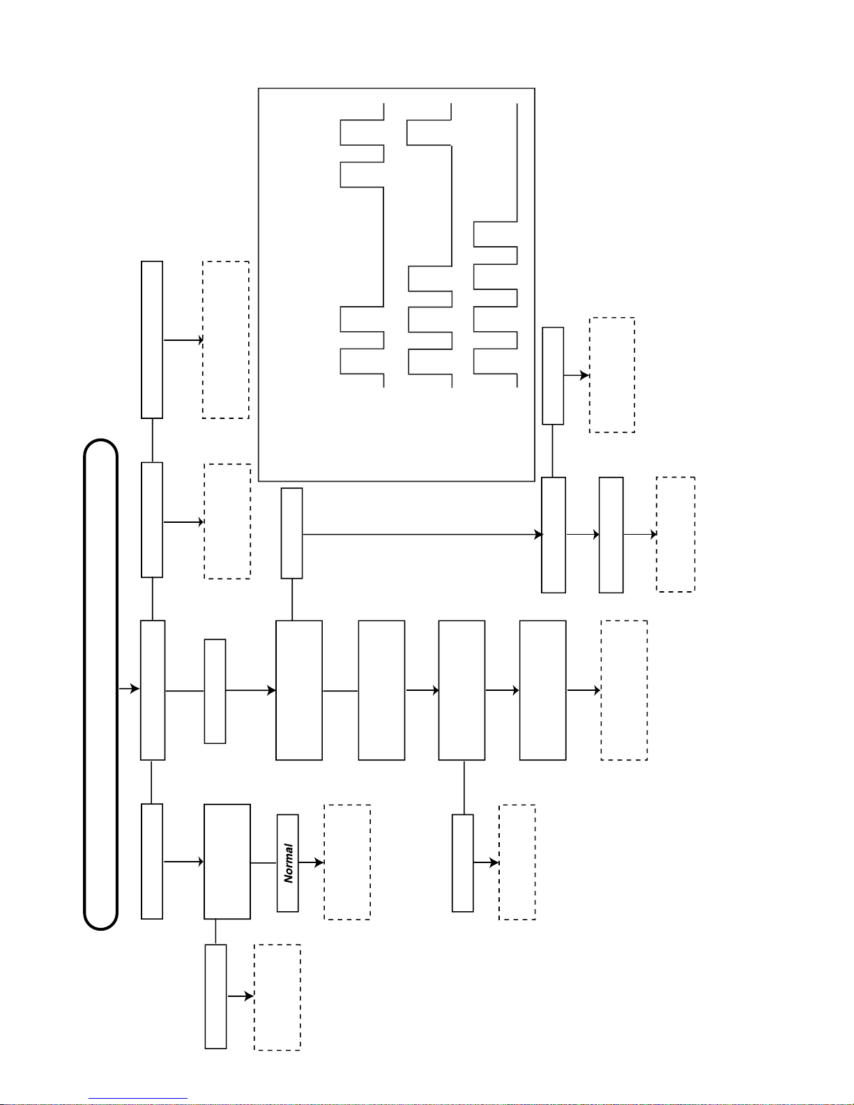
TROUBLE SHOOTING TABLE
NO PICTURE
Does the snow noise appear on
the CRT at max contrast and
brightness control?
Does approx.30V appear
at pin (9) of TU201(tuner)
Check L204, D606 and
R618
Check TU201 and their
peripheral parts.
Check pin(1) and (2) of
IC201
Check pin(51) of IC 1001
Does noise or signal
appear?
Check IC1001 RGB output
Normal?
Check pin(1), (2) and (3) of
IC850 Signal or Noise?
Check R616(Heater), Screen
connection and Peripheral
circuits of T602(FBT) and CRT
Check TU201(tuner),
SF202 and Peripheral
parts.
Check IC201, Q201 and
their Peripheral circuits.
Check IC1001 and their
Peripheral circuits.
Check "CJ" connection,
IC850 and their Peripheral
circuits
Snow noise increase
No Snow noise
(Noise or signal appear)
(Noise)
(Signal)
8
Page 9
SX76NF8
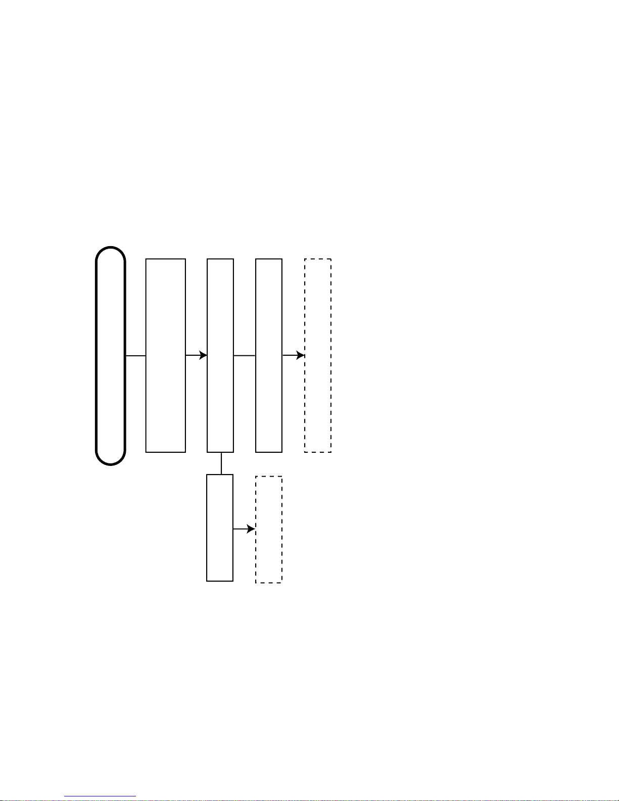
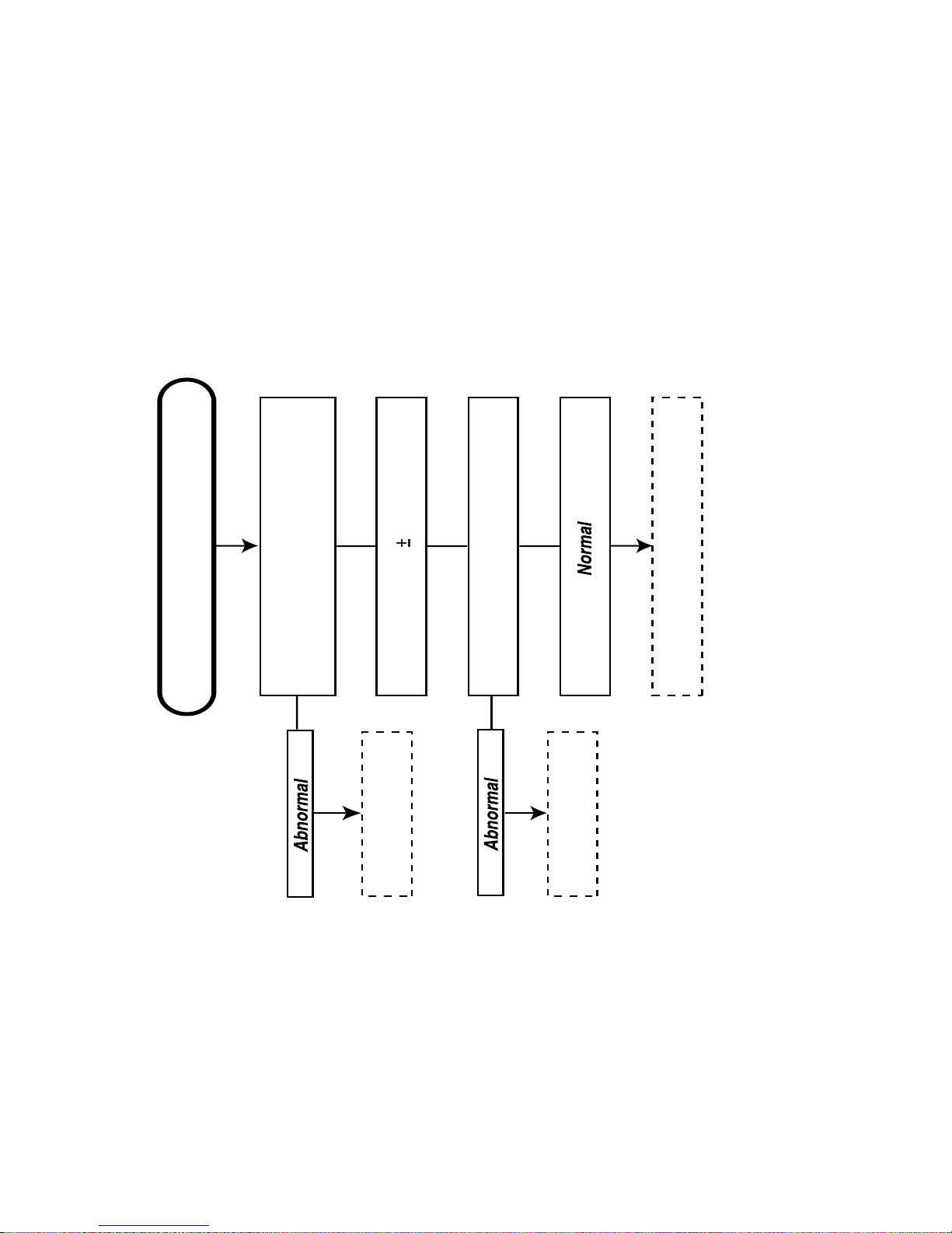
TROUBLE SHOOTING TABLE
NO SOUND
Check sound setting by R/C.
Siganl should be received.
Check C1302(C1309) Voltage
Approx. 15(-15V)
Check IC1301, IC1302 and Speaker
0V
Check L1302, L1303
D752 and D753
9
Page 10
SX76NF8
TROUBLE SHOOTING TABLE
NO FUNCTION (NO SOUND AND NO PICTURE)
Is D2201(LED) on a light?
Check IC 1001
94pin INPUT
Check C755 Voltage
Immediately appear
approx. 145V, and turn
to 0V soon.
Check C752 Voltage
Check C715Voltage
Refer to "No
Picture", trouble
shooting
Check IC701,
Q702 and T703
Check IC1001, IC1003,
IC301, IC201, TU201(Refer
to LED FLASHING CODES)
GREEN RED
Approx. 320V
Completely 0V
No Input Pulse
FLASHIN
Check D754 and
IC751
Check Vertical
Circuit
Check Q1012,
D1016 and SP wire
"SS" connection.
0V
Check R718,
F2001 and "AA"
connection
0V
Green
Green
Green
Red
Red
Red
No Light
Immediately appear
approx. 8V, and turn to
0V soon.
Check D752, D753,
C756, C757 and IC752
LED FLASHING CODES
If the TV set does not work and the power LED is flashing "Red <=>Green",
follow the sequence according to the information below, as a guide to fault
finding.
1.Unable to read or write into NMV;66% Green,33% Red twice and Red for
a second.
2.MSP failure;66% Green,33% Red for three times and Red for a second.
3.VCT failure;66% Green,33% Red for four times and Red for a second.
10
Page 11
SX76NF8
TROUBLE SHOOTING TABLE
NO VERTICAL SCAN
Check the Voltage at pin(15)(1)
of IC502
Normal approx. 14V
Check IC502 and related circuits
Check D601, D605,
R608 and R614
Check IC1001 and
peripheral parts
Check vertical trigger pulse at
pin(12)(13) of IC502
11
Page 12
SX76NF8
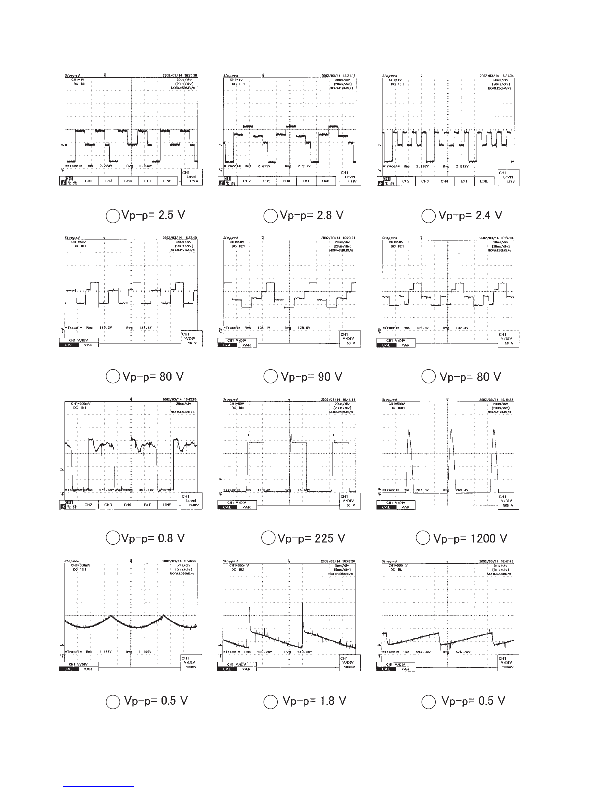
WAVE FORMS
1
4 5 6
2 3
7
10
8
11 12
12
9
Page 13
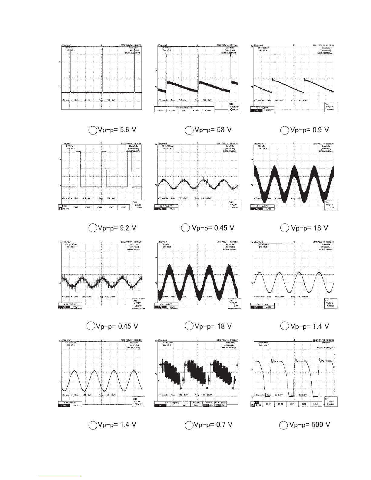
13 14 15
SX76NF8
16 17 18
19
20 21
22 23 24
13
Page 14
SX76NF8
CHASSIS LAYOUT
14
Page 15
SX76NF8
15
Page 16

SX76NF8
BLOCK DIAGRAM
16
Page 17

SX76NF8
17
Page 18

SX76NF8
DESCRIPTION OF SCHEMATIC DIAGRAM
SAFETY NOTES:
1. DISCONNECT THE AC PLUG FROM THE AC OUTLET BEFORE
REPLACING PARTS.
2. SEMICONDUCTOR HEAT SINKS SHOULD BE REGARDED AS
POTENTIAL SHOCK HAZARDS WHEN THE CHASSIS IS OPERATING.
IMPORTANT SAFETY NOTICE:
PARTS MARKED WITH “å” ( ) ARE IMPORTANT FOR
MAINTAINING THE SAFETY OF THE SET. BE SURE TO REPLACE THESE PARTS WITH SPECIFIED ONES FOR MAINTAINING THE SAFETY AND PERFORMANCE OF THE SET.
SERVICE PRECAUTION:
THE AREA ENCLOSED BY THIS LINE (
CONNECTED WITH AC MAINS VOLTAGE.
WHEN SERVICING THE AREA, CONNECT AN ISOLATING TRANSFORMER BETWEEN TV RECEIVER AND AC LINE TO ELIMINATE
HAZARD OF ELECTRIC SHOCK.
) IS DIRECTLY
NOTES:
1. The unit of resistance “ohm” is omitted.
(K = 1000 ohms, M = Meg ohm).
2. All resistors are 1/16 watt, unless otherwise noted.
3. All capacitors are µF, unless therwise noted. (P = µµF).
VOLTAGE MEASUREMENT CONDITIONS:
1. Voltage in parenthesis measured with no Signal.
2. Voltages without parenthesis measured with PAL Colour-Signal.
3. All the voltages in each point are measured with high impedence
volt-meter.
WAVEFORM MEASUREMENT CONDITIONS:
1. Colour bar generator signal of 2.0V peak to peak applied at Base
of Video Buffer Amp. Q254.
2. Approximately 4.0 V AGC bias.
18
Page 19

SX76NF8
A
B
C
D
E
F
G
H
I
J
12345678910
SCHEMATIC DIAGRAM
CRT UNIT
19
Page 20

SX76NF8
J
I
H
G
MAIN UNIT-1/3
F
E
D
C
B
A
12345678910
20
Page 21

SX76NF8
10 11 12 13 14 15 16 17 18 19
21
Page 22

SX76NF8
J
I
H
G
MAIN UNIT-2/3
F
E
D
C
B
A
12345678910
22
Page 23

SX76NF8
10 11 12 13 14 15 16 17 18 19
23
Page 24

SX76NF8
J
I
H
G
MAIN UNIT-3/3
F
E
D
C
B
A
12345678910
24
Page 25

SX76NF8
10 11 12 13 14 15 16 17 18 19
25
Page 26

SX76NF8
J
I
H
G
CONTROL UNIT
F
E
D
C
B
A
12345678910
26
Page 27

SX76NF8
10 11 12 13 14 15 16 17 18 19
27
Page 28

SX76NF8
J
I
H
G
DF UNIT
F
E
D
C
B
A
12345678910
28
Page 29

SX76NF8
A
B
C
D
E
F
G
H
I
J
12345678910
LED UNIT
KEY UNIT
29
Page 30

SX76NF8
J
I
H
G
SUB WOOFER UNIT
F
E
D
C
B
A
12345678910
30
Page 31

SX76NF8
A
B
C
D
E
F
G
H
I
J
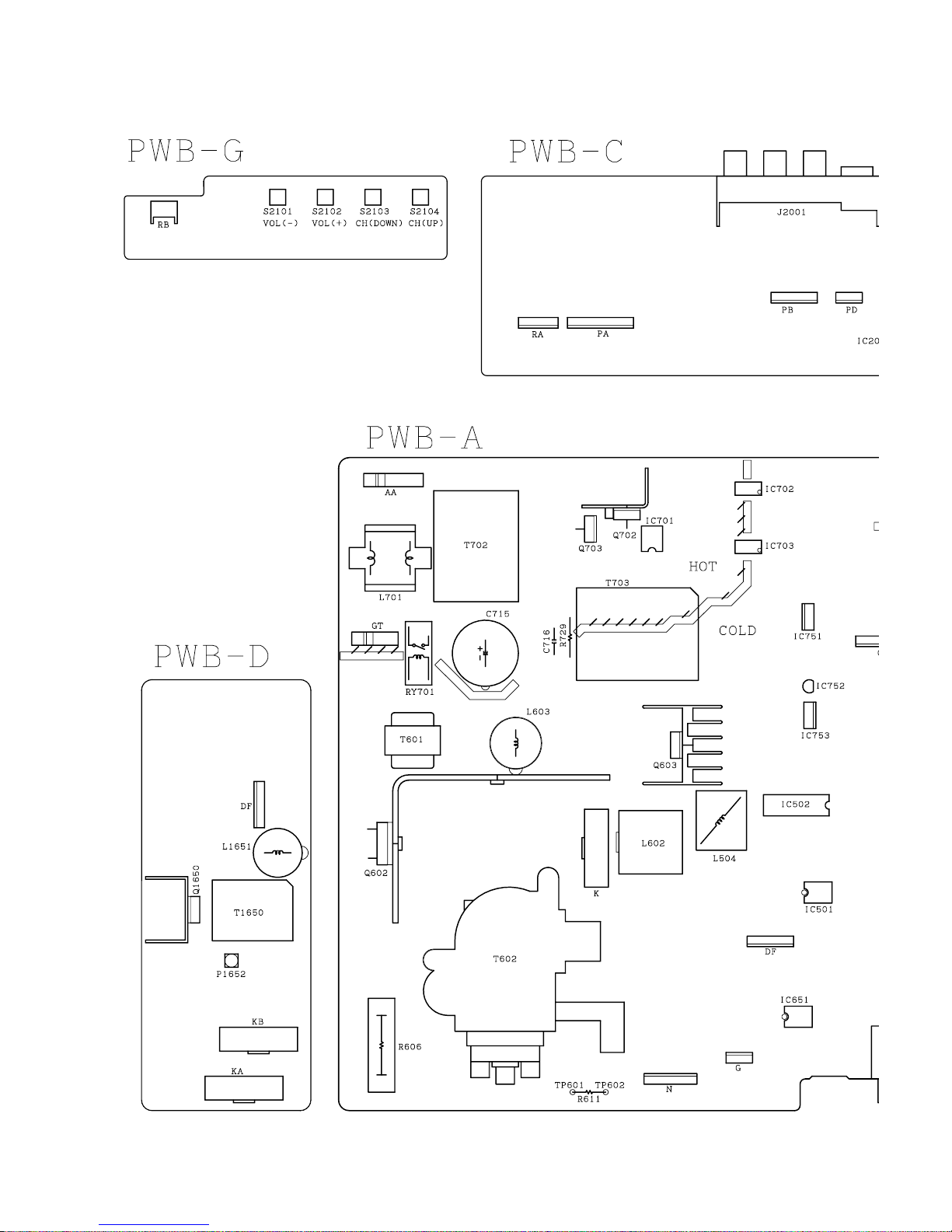
12345678910
PRINTED WIRING BOARD ASSEMBLIES
PWB-B: CRT UNIT
PWB-D: DF UNIT
31
Page 32

SX76NF8
J
I
H
G
PWB-A: MAIN UNIT (COPPER SIDE)
F
E
D
C
B
A
12345678910
32
Page 33

SX76NF8
10 11 12 13 14 15 16 17 18 19
33
Page 34

SX76NF8
J
I
H
G
PWB-A: MAIN UNIT (Chip Parts Side)
F
E
D
C
B
A
12345678910
34
Page 35

SX76NF8
10 11 12 13 14 15 16 17 18 19
35
Page 36

SX76NF8
J
I
H
G
F
E
D
C
B
A
12345678910
PWB-C: CONTROL UNIT
36
Page 37

SX76NF8
A
B
C
D
E
F
G
H
I
J
12345678910
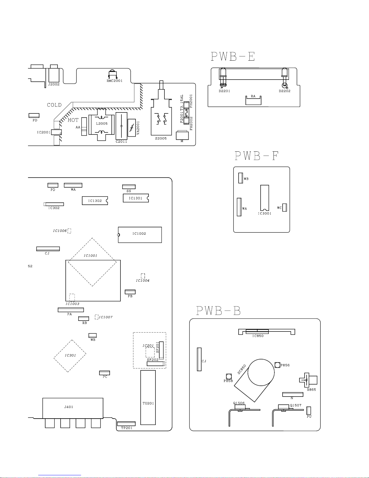
PWB-E: LED UNIT
PWB-F: SUB WOOFER UNIT
PWB-G: KEY UNIT
37
Page 38

SX76NF8
Ref. No. Part No. ★ Description Code
REPLACEMENT PARTS LIST
PARTS REPLACEMENT
Replacement parts which have these special safety characteristics are
identified in this manual; electrical components having such features
are identified by "å" in the Replacement Parts Lists.
The use of a substitute replacement part which does not have the same
safety characteristics as the factory recommended replacement parts
shown in this service manual may create shock, fire or other hazards.
"HOW TO ORDER REPLACEMENT PARTS"
To have your order filled promptly and correctly, please furnish the following
informations.
1. MODEL NUMBER 2. REF. NO.
3. PART NO. 4. DESCRIPTION
MARK : SPARE PARTS-DELIVERY SECTION.
Ref. No. Part No. ★ Description Code
PICTURE TUBE
å VB76LTL352WFS R Picture Tube DV
å L799 RCiLGA035WJZZ R Degaussing Coil AT
PWB-A DUNTKB557WEV0 - MAIN Unit —
PWB-B DUNTKB558WEV0 - CRT Unit —
PWB-C DUNTKB559WEV0 - CONTROL Unit —
PWB-D DUNTKB560WEV0 - DF Unit —
PWB-E DUNTKB563WEV0 - LED Unit —
PWB-F DUNTKB700WEV0 - SUB WOOFER Unit —
PWB-G DUNTKB562WEV0 - KEY Unit —
NOTE: THE PARTS HERES SHOWN ARE SUPPLIED AS AN
å TU201 VTUCTF5511+++ R Tuner AZ
IC201 RH-iX1799BMZZY R I.C. AQ
IC301 RH-iX1853BMZZY R I.C. BE
IC302 VHiM5218AL/-1 R M5218L AD
IC501 VHiUPC358C/-1 R UPC358C AD
IC502 VHiSTV9380+-2 R STV9380 AP
IC651 VHiUPC358C/-1 R UPC358C AD
IC701 VHiTEA1507/-1 R TEA1507P/N1 AL
å IC702 RH-FX0008GEZZ R PC123FY8 AE
å IC703 RH-FX0008GEZZ R PC123FY8 AE
IC751 VHiPQ05RD08-1 R PQ05RD08 AF
IC752 VHiKA78S05P-1+ R KIA78S05P AD
IC753 VHiKA7808AP-1 R KIA7808API AE
IC1001 RH-iXA186WJZZQ R VCT3834A-QH-C4 BM
RCiLG0443CEZZ R Degaussing Coil AL
RCiLHA057WJZZ R Deflection Yoke BT
QEARCA015WJZZ R Grounding Strap AL
PMAGF3087CEZZ R Magnet AL
PMAGG3006CEZZ R Magnet AC
PRINTED WIRING BOARD ASSEMBLIES
(NOT REPLACEMENT ITEM)
DUNTKB557WEV0
PWB-A MAIN UNIT
TUNER
ASSEMBLY NOT INDEPENDENTLY.
INTEGRATED CIRCUITS
Ref. No. Part No. ★ Description Code
IC1002 RH-iXA424WJZZ R I.C. AW
IC1003 VHiBR24C64F-1Y R BR24C64F-E2 AL
IC1004 VHiMM1503XN-1Y R MM1503XNRE AE
IC1006 VHiBA033LBS-1Y R BA033LBSG-TR AF
IC1007 VHiBA033LBS-1Y R BA033LBSG-TR AF
IC1301 VHiTDA7480/-1 R I.C. AM
IC1302 VHiTDA7480/-1 R I.C. AM
TRANSISTORS
Q201 VS2SA1037KQ-1Y R 2SA1037KQ AA
Q206 VS2SC2412KQ-1Y R 2SC2412KQ AA
Q301 VS2SC2412KQ-1Y R 2SC2412KQ AA
Q302 VS2SA1037KQ-1Y R 2SA1037KQ AA
Q305 VSDTC314TK/-1Y R DTC314TK AC
Q306 VSDTC314TK/-1Y R DTC314TK AC
Q601 VS2SC2482//-1+ R 2SC2482 AD
Q602 VS2SC5450//1E R 2SC5450 AL
Q603 VS2SD1830//1E R 2SD1830 AF
Q604 VS2SA1246//1E+ R 2SA1246 AE
Q651 VS2SC3228Y/-1+ R 2SC3228Y AD
Q652 VS2SA1275Y/-1+ R 2SA1275Y AD
Q701 VS2SC2412KQ-1Y R 2SC2412KQ AA
Q702 VSSPA07N60C-1 R SPA07N60C AN
Q703 VSSTP4NC80Z1E R STP4NC80Z1E AK
Q704 VS2SC3198-G-1+ R 2SC3198-G AA
Q751 VS2SC2412KQ-1Y R 2SC2412KQ AA
Q752 VS2SA1037KQ-1Y R 2SA1037KQ AA
Q753 VS2SA1037KQ-1Y R 2SA1037KQ AA
Q754 VS2SC2412KQ-1Y R 2SC2412KQ AA
Q755 VS2SC2412KQ-1Y R 2SC2412KQ AA
Q756 VS2SC2412KQ-1Y R 2SC2412KQ AA
Q757 VS2SA1037KQ-1Y R 2SA1037KQ AA
Q759 VS2SA1037KQ-1Y R 2SA1037KQ AA
Q762 VS2SC3198-G-1+ R 2SC3198-G AA
Q1006 VS2SC2412KQ-1Y R 2SC2412KQ AA
Q1007 VS2SC2412KQ-1Y R 2SC2412KQ AA
Q1008 VS2SC2412KQ-1Y R 2SC2412KQ AA
Q1011 VS2SC2412KQ-1Y R 2SC2412KQ AA
Q1012 VS2SA1037KQ-1Y R 2SA1037KQ AA
Q1013 VS2SC2412KQ-1Y R 2SC2412KQ AA
Q1301 VS2SA1037KQ-1Y R 2SA1037KQ AA
Q1302 VS2SA1037KQ-1Y R 2SA1037KQ AA
Q1303 VS2SC2412KQ-1Y R 2SC2412KQ AA
Q1304 VS2SC2412KQ-1Y R 2SC2412KQ AA
Q1305 VS2SC2412KQ-1Y R 2SC2412KQ AA
DIODES AND LED’S
D202 RH-EX1394CEZZY R Zener Diode 5.73V AB
D203 RH-EX1394CEZZY R Zener Diode 5.73V AB
D303 RH-EX1398CEZZY R Zener Diode 8.36V AB
D304 RH-EX1398CEZZY R Zener Diode 8.36V AB
D305 RH-EX1398CEZZY R Zener Diode 8.36V AB
D306 RH-EX1398CEZZY R Zener Diode 8.36V AB
D308 RH-EX1398CEZZY R Zener Diode 8.36V AB
D309 RH-EX1398CEZZY R Zener Diode 8.36V AB
D310 RH-EX1398CEZZY R Zener Diode 8.36V AB
D312 RH-EX1394CEZZY R Zener Diode 5.73V AB
D313 RH-EX1394CEZZY R Zener Diode 5.73V AB
D314 RH-EX1398CEZZY R Zener Diode 8.36V AB
D315 RH-EX1398CEZZY R Zener Diode 8.36V AB
D401 RH-EX1397CEZZY R Zener Diode 7.6V AB
D402 RH-EX1397CEZZY R Zener Diode 7.6V AB
D403 RH-EX1397CEZZY R Zener Diode 7.6V AB
D404 RH-EX1397CEZZY R Zener Diode 7.6V AB
D405 RH-EX1397CEZZY R Zener Diode 7.6V AB
D406 RH-EX1397CEZZY R Zener Diode 7.6V AB
D501 VHDHSU119//-1Y R HSU119 AB
D502 VHDHSU119//-1Y R HSU119 AB
D503 RH-DX0487CEZZY R Diode AC
D756 VHiMM1431AT-1+ R MM1431ATT AD
D601 RH-DX0295CEZZ R Diode AD
D602 RH-DX0514CEZZ R Diode AF
D603 RH-DX0229CEZZ R Diode AF
D604 RH-DX0302CEZZY R Diode AC
D605 RH-DX0295CEZZ R Diode AD
D606 RH-EX0673GEZZY R Zener Diode 30.51V AB
38
Page 39

SX76NF8
Ref. No. Part No. ★ Description Code
D607 RH-DX0487CEZZY R Diode AC
D608 RH-EX0630GEZZY R Zener Diode 9.01V AA
D651 RH-EX0718GEZZY R Zener Diode 2.63V AB
D701 VHDHSU119//-1Y R HSU119 AB
D703 RH-DX0279CEZZY R Diode AB
D704 RH-DX0279CEZZY R Diode AB
D705 RH-DX0321CEZZY R Diode AC
D706 VHSSF0R5G43-1+ R SI.Control Rectifier AE
D707 RH-DX0321CEZZY R Diode AC
D708 VHD1SS244//-1Y R 1SS244 AB
D709 RH-DX0279CEZZY R Diode AB
D710 RH-EX0645GEZZY R Zener Diode 14.13V AB
D711 RH-DX0279CEZZY R Diode AB
D712 VHDHSU119//-1Y R HSU119 AB
D751 RH-EX0655GEZZY R Zener Diode 19.59V AB
D752 RH-DX0460CEZZ R Diode AF
D753 RH-DX0460CEZZ R Diode AF
D754 RH-DX0406CEZZY R Diode AD
D755 RH-DX0461CEZZ R Diode AG
D758 VHDHSU119//-1Y R HSU119 AB
D759 VHDHSU119//-1Y R HSU119 AB
D760 VHDHSU119//-1Y R HSU119 AB
D761 VHDHSU119//-1Y R HSU119 AB
D763 VHDHSU119//-1Y R HSU119 AB
D764 RH-EX1274CEZZY R Zener Diode 13.49V AB
D765 VHD1SS119//1EY R 1SS119 AA
D766 VHDHSU119//-1Y R HSU119 AB
D767 RH-EX0641GEZZY R Zener Diode 12.35V AA
D768 VHDHSU119//-1Y R HSU119 AB
D770 VHDHSU119//-1Y R HSU119 AB
D773 VHDHSU119//-1Y R HSU119 AB
D774 VHDHSU119//-1Y R HSU119 AB
D775 VHDHSU119//-1Y R HSU119 AB
D776 VHD1SS119//1EY R 1SS119 AA
D780 VHDHSU119//-1Y R HSU119 AB
D783 VHDHSU119//-1Y R HSU119 AB
D784 VHDHSU119//-1Y R HSU119 AB
D785 RH-EX0619GEZZY R Zener Diode 6.44V AA
D786 VHDHSU119//-1Y R HSU119 AB
D1002 RH-EX1394CEZZY R Zener Diode 5.73V AB
D1003 VHDHSU119//-1Y R HSU119 AB
D1004 RH-EX1394CEZZY R Zener Diode 5.73V AB
D1005 RH-EX1241CEZZY R Zener Diode 4.75V AB
D1006 VHDHSU119//-1Y R HSU119 AB
D1007 VHDHSU119//-1Y R HSU119 AB
D1009 RH-EX1241CEZZY R Zener Diode 4.75V AB
D1010 RH-EX1394CEZZY R Zener Diode 5.73V AB
D1011 RH-EX1393CEZZY R Zener Diode 5.2V AB
D1012 RH-EX1394CEZZY R Zener Diode 5.73V AB
D1013 RH-EX1394CEZZY R Zener Diode 5.73V AB
D1014 RH-EX1394CEZZY R Zener Diode 5.73V AB
D1016 VHDHSU119//-1Y R HSU119 AB
D1017 VHDHSU119//-1Y R HSU119 AB
D1018 VHDHSU119//-1Y R HSU119 AB
D1019 VHDHSU119//-1Y R HSU119 AB
D1020 VHD1SS119//1EY R 1SS119 AA
D1021 RH-EX1394CEZZY R Zener Diode 5.73V AB
D1022 RH-EX1394CEZZY R Zener Diode 5.73V AB
D1023 RH-EX1394CEZZY R Zener Diode 5.73V AB
D1024 RH-EX1394CEZZY R Zener Diode 5.73V AB
D1025 RH-EX1394CEZZY R Zener Diode 5.73V AB
D1026 RH-EX1394CEZZY R Zener Diode 5.73V AB
D1027 RH-EX1394CEZZY R Zener Diode 5.73V AB
D1028 RH-EX1394CEZZY R Zener Diode 5.73V AB
D1030 RH-EX1394CEZZY R Zener Diode 5.73V AB
D1031 RH-EX1394CEZZY R Zener Diode 5.73V AB
D1032 RH-EX1394CEZZY R Zener Diode 5.73V AB
D1033 RH-EX1394CEZZY R Zener Diode 5.73V AB
D1034 RH-EX1394CEZZY R Zener Diode 5.73V AB
D1301 VHDHSU119//-1Y R HSU119 AB
D1302 VHDHSU119//-1Y R HSU119 AB
D1303 VHDHSU119//-1Y R HSU119 AB
D1304 RH-EX1394CEZZY R Zener Diode 5.73V AB
D1305 VHDHSU119//-1Y R HSU119 AB
D1306 VHDHSU119//-1Y R HSU119 AB
Ref. No. Part No. ★ Description Code
PACKAGED CIRCUITS
PR701 RMPTP0102CEZZ R Packaged Circuit AG
X201 RCRSAA029WJZZ R Crystal, 4MHz AF
X301 RCRSB0249GEZZ+ R Crystal, 18.432MHz AF
X1001 RCRSAA030WJZZ R Crystal, 20.25MHz AH
COILS AND TRANSFORMERS
L201 VP-DF6R8K0000Y R Peaking 6.8µHAB
L202 VP-DF120K0000Y R Peaking 12µHAB
L203 VP-DF100K0000Y R Peaking 10µHAB
L204 VP-DF3R3K0000Y R Peaking 3.3µHAE
L301 VP-XF100K0000Y R Peaking 10µHAB
L302 VP-DF120K0000Y R Peaking 12µHAB
L303 VP-XF100K0000Y R Peaking 10µHAB
L501 VP-XF8R2K0000Y R Peaking 8.2µHAB
L504 RCiLP0271BMZZ R Coil AH
L602 RCiLZ1043CEZZ R Coil AM
L603 RCiLZ1053CEZZ R Coil AG
å L701 RCiLF0108BMZZ R Coil AK
L751 RCiLP0212CEZZ+ R Coil AE
L752 VP-CF3R3K0000Y R Peaking 3.3µHAC
L1002 VP-XF1R0M0000Y R Peaking 1µHAB
L1003 VP-XF1R0M0000Y R Peaking 1µHAB
L1004 VP-XF1R0M0000Y R Peaking 1µHAB
L1005 VP-DF1R0M0000Y R Peaking 1µHAB
L1006 VP-XF1R0M0000Y R Peaking 1µHAB
L1007 VP-DF1R0M0000Y R Peaking 1µHAB
L1008 VP-DF3R3K0000Y R Peaking 3.3µHAB
L1009 VP-XF1R0M0000Y R Peaking 1µHAB
L1010 VP-DF1R0M0000Y R Peaking 1µHAB
L1011 VP-DF1R0M0000Y R Peaking 1µHAB
L1012 VP-XF1R0M0000Y R Peaking 1µHAB
L1301 RCiLP0195CEZZ+ R Coil AB
L1302 VP-CF3R3K0000Y R Peaking 3.3µHAC
L1303 VP-CF3R3K0000Y R Peaking 3.3µHAC
L1304 VP-CF3R3K0000Y R Peaking 3.3µHAC
L1305 VP-CF3R3K0000Y R Peaking 3.3µHAC
L1306 RCiLP0195CEZZ+ R Coil AB
SF201 RFiLC0286BMZZ R Filter AH
SF202 RFiLC0278BMZZ R Filter AM
T601 RTRNZ0731CEZZ R Transformer AG
å T602 RTRNFA045WJZZ R H-Volt Transformer AK
å T702 RTRNCA003WJZZ R Choke Transformer AQ
å T703 RTRNWA079WJZZ R Transformer AQ
CAPACITORS
C201
C202
C203
C204
C205
C206
C207
C209
C210
C211
C212 VCFYFA1HA474J+ R 0.47 50V Mylar AC
C213 VCFYFA1HA684J+ R 0.68 50V Mylar AC
C214
C215 VCFYFA1HA224J+ R 0.22 50V Mylar AB
C216
C217
C218
C219
C220
C221
C223
C225
C229
C230
C301
C302
C303
C304
C305
C306
VCEA0A1CW336M+
VCCCCY1HH220JY
VCCCCY1HH270JY
VCEA0A0JW477M+
VCKYCY1CF334ZY
VCEA0A0JW107M+
VCCCCY1HH100DY
VCKYCY1HB103KY
VCCCCY1HH391JY
VCKYCY1HB103KY
VCEA0A0JW227M+
VCKYCY1HB152KY
VCEA0A0JW107M+
VCKYCY1HF223ZY
VCKYCY1EF104ZY
VCCCCY1HH100DY
VCCCCY1HH100DY
VCKYCY1HF103ZY
VCEA0A1CW106M+
VCEA0A1HW106M+
VCKYCY1HB102KY
VCKYCY1EF104ZY
VCKYCY1EF473ZY
VCKYCY1HB102KY
VCKYCY1HB102KY
VCKYCY1HB102KY
VCKYCY1HB681KY
R 33 16V Electrolytic AB
R 22p 50V Ceramic AA
R 27p 50V Ceramic AA
R 470 6.3V Electrolytic AC
R 0.33 16V Ceramic AB
R 100 6.3V Electrolytic AB
R 10p 50V Ceramic AA
R 0.01 50V Ceramic AA
R 390p 50V Ceramic AB
R 0.01 50V Ceramic AA
R 220 6.3V Electrolytic AB
R 1500p 50V Ceramic AA
R 100 6.3V Electrolytic AB
R 0.022 50V Ceramic AB
R 0.1 25V Ceramic AA
R 10p 50V Ceramic AA
R 10p 50V Ceramic AA
R 0.01 50V Ceramic AA
R 10 16V Electrolytic AB
R 10 50V Electrolytic AB
R 1000p 50V Ceramic AA
R 0.1 25V Ceramic AA
R 0.047 25V Ceramic AA
R 1000p 50V Ceramic AA
R 1000p 50V Ceramic AA
R 1000p 50V Ceramic AA
R 680p 50V Ceramic AA
39
Page 40

SX76NF8
Ref. No. Part No. ★ Description Code
C307
C308
C309
C310
C311
C312
C313
C314
C315
C317 VCFYFA1HA334J+ R 0.33 50V Mylar AB
C318 VCFYFA1HA334J+ R 0.33 50V Mylar AB
C319 VCFYFA1HA334J+ R 0.33 50V Mylar AB
C320 VCFYFA1HA334J+ R 0.33 50V Mylar AB
C321
C322
C323
C324
C325
C326
C327
C328
C329
C330
C337
C338
C343 VCFYFA1HA334J+ R 0.33 50V Mylar AB
C344 VCFYFA1HA334J+ R 0.33 50V Mylar AB
C345
C346
C347
C348
C349
C350
C353
C354
C355
C367
C368
C401 VCFYFA1HA684J+ R 0.68 50V Mylar AC
C402 VCFYFA1HA684J+ R 0.68 50V Mylar AC
C404 VCFYFA1HA684J+ R 0.68 50V Mylar AC
C405 VCFYFA1HA684J+ R 0.68 50V Mylar AC
C406 VCFYFA1HA684J+ R 0.68 50V Mylar AC
C501
C502
C503 VCFYAA2EA104J+ R 0.1 250V Mylar AD
C504
C505
C506
C507
C508
C509
C510
C511
C512
C513
C514
C515
C516
C517 VCFYFA1HA224J+ R 0.22 50V Mylar AB
C518
C520 VCFYAH2AA474K R 0.47 100V Mylar AE
C521
C526
C527
C529
C530
C601
C602
C603
C604
C605
C606 RC-KZ0033CEZZ R 150p 2kV Ceramic AB
C607 VCFYAA2EA104J+ R 0.1 250V Mylar AD
C608 VCFPGU2EC244J R 0.24 250V M.Polypro AF
C609 VCFPVC3ZA123H R 0.012 1.8kVM.Polypro AD
C611 VCQPPC2JB333J R 0.033 630V Mylar AC
VCKYCY1HB681KY
VCEA0A1CW106M+
VCEA0A1CW106M+
VCKYCY1EF104ZY
VCEA0A1CW337M+
VCEA0A1CW106M+
VCEA0A1CW106M+
VCEA0A1HW335M+
VCKYCY1EF104ZY
VCEA0A1CW106M+
VCKYCY1EF104ZY
VCKYCY1EF104ZY
VCCCCY1HH470JY
VCCCCY1HH470JY
VCCCCY1HH5R0CY
VCCCCY1HH470JY
VCCCCY1HH5R0CY
VCKYCY1EF104ZY
VCEA0A0JW227M+
VCKYCY1HB681KY
VCKYCY1HB681KY
VCEA0A1EW107M+
VCEA0A1EW107M+
VCKYCY1CF224ZY
VCKYCY1CF224ZY
VCKYCY1HB102KY
VCKYCY1HB102KY
VCKYCY1HB102KY
VCKYCY1HB102KY
VCEA0A0JW227M+
VCEA0A1CW106M+
VCEA0A1CW106M+
VCKYPA1HB391K+
VCEA0A1VW227M+
VCE9EA1HW335M+
VCKYPA1HB391K+
VCKYPA2HB102K+
VCEA0A1VW106M+
VCKYPA2HB102K+
VCEA0A1EW477M
VCQYTA1HM104J+
VCQYTA1HM104J+
VCEA0A1EW477M
VCEA0A1VW107M+
VCKYPA1HB471K+
VCKYPA1HB472K+
VCQYTA1HM104J+
VCQYTA1HM104J+
VCCCCY1HH471JY
VCQYTA1HM683J+
VCQYTA1HM683J+
VCE9GA1CW106M+
VCEA0A1HW107M+
VCKYPA1HB102K+
VCKYPA2HB561K+
VCKYPA2HB102K+
VCEA0A1EW108M
VCKYPA1HB472K+
R 680p 50V Ceramic AA
R 10 16V Electrolytic AB
R 10 16V Electrolytic AB
R 0.1 25V Ceramic AA
R 330 16V Electrolytic AC
R 10 16V Electrolytic AB
R 10 16V Electrolytic AB
R 3.3 50V Electrolytic AB
R 0.1 25V Ceramic AA
R 10 16V Electrolytic AB
R 0.1 25V Ceramic AA
R 0.1 25V Ceramic AA
R 47p 50V Ceramic AA
R 47p 50V Ceramic AA
R 5.0p 50V Ceramic AA
R 47p 50V Ceramic AA
R 5.0p 50V Ceramic AA
R 0.1 25V Ceramic AA
R 220 6.3V Electrolytic AB
R 680p 50V Ceramic AA
R 680p 50V Ceramic AA
R 100 25V Electrolytic AC
R 100 25V Electrolytic AC
R 0.22 16V Ceramic AB
R 0.22 16V Ceramic AB
R 1000p 50V Ceramic AA
R 1000p 50V Ceramic AA
R 1000p 50V Ceramic AA
R 1000p 50V Ceramic AA
R 220 6.3V Electrolytic AB
R 10 16V Electrolytic AB
R 10 16V Electrolytic AB
R 390p 50V Ceramic AA
R 220 35V Electrolytic AC
R 3.3 50V Elect.(N,P) AB
R 390p 50V Ceramic AA
R 1000p 500V Ceramic AA
R 10 35V Electrolytic AB
R 1000p 500V Ceramic AA
R 470 25V Electrolytic AD
R 0.1 50V Mylar AB
R 0.1 50V Mylar AB
R 470 25V Electrolytic AD
R 100 35V Electrolytic AC
R 470p 50V Ceramic AA
R 4700p 50V Ceramic AB
R 0.1 50V Mylar AB
R 0.1 50V Mylar AB
R 470p 50V Ceramic AA
R 0.068 50V Mylar AB
R 0.068 50V Mylar AB
R 10 16V Elect.(N,P) AB
R 100 50V Electrolytic AB
R 1000p 50V Ceramic AA
R 560p 500V Ceramic AA
R 1000p 500V Ceramic AA
R 1000 25V Electrolytic AD
R 4700p 50V Ceramic AB
Ref. No. Part No. ★ Description Code
C613 RC-KZ0036CEZZ R 330p 2kV Ceramic AB
C615
C616
C617 RC-FZ0377CEZZ R 4.7 100V Mylar AF
C618
C619
C620 VCEA0A1EW108M R 1000 25V Electrolytic AD
C621
C622 VCFPVC2DB224J R 0.22 200V M.Polypro AE
C651
C652
C653
C701 RC-KZ0029CEZZ+ R 0.01 250V Ceramic AC
C702 RC-KZ0029CEZZ+ R 0.01 250V Ceramic AC
C704
C705
C706
C707 RC-KZ0029CEZZ+ R 0.01 250V Ceramic AC
C708
C709 RC-KZ0296CEZZ+ R 470p 2kV Ceramic AC
C710 VCFPVC3CA822H R 8200p 1.6kV M.Polypro AE
C712 RC-KZ0038CEZZ R 470p 2kV Ceramic AB
C713 VCQPPC2JB333K R 0.033 630V Mylar AC
C714
C715 RC-EZ1046CEZZ R 220 400V Electrolytic AN
å C716 RC-KZ0106GEZZ R 3300p 4kV Ceramic AG
C717 RC-KZ0038CEZZ R 470p 2kV Ceramic AB
C718 RC-KZ0038CEZZ R 470p 2kV Ceramic AB
C751
C752 VCEA0A1CW108M R 1000 16V Electrolytic AD
C753
C754 RC-EZA035WJZZ R 100 200V Electrolytic AH
C755 RC-EZA035WJZZ R 100 200V Electrolytic AH
C756 VCEA0A1EW108M R 1000 25V Electrolytic AD
C757 VCEA0A1EW108M R 1000 25V Electrolytic AD
C758
C760
C764
C766
C767
C768
C769
C770
C771
C772
C773
C774
C775
C776
C777
C780
C1001
C1002
C1003
C1004
C1005
C1006
C1007
C1008
C1009
C1010
C1011
C1012
C1013
C1014
C1015
C1016
C1017
C1019
C1020
C1021
C1022
C1023
C1024
C1025
C1026
C1027
VCKYPA2HB102K+
VCEA0A2EW106M
VCKYPA2HB102K+
VCEA0A1HW106M+
VCEA0A1VW107M+
VCEA0A1VW106M+
VCEA0A1VW106M+
VCEA0A1VW106M+
VCKYPA1HB102K+
VCEA0A1EW226M+
VCQYTA1HM473J+
VCQYTA1HM104J+
VCEA0A1HW226M+
VCEA0A2AW105M+
VCQYTA1HM273J+
VCQYTA1HM104J+
VCEA0A1CW106M+
VCEA0A1CW476M+
VCEA0A1EW476M+
VCKYCY1HB103KY
VCEA0A1CW476M+
VCEA0A1HW106M+
VCEA0A1CW106M+
VCEA0A1EW227M+
VCEA0A1CW476M+
VCEA0A1HW225M+
VCE9EA1HW105M+
VCEA0A1HW106M+
VCKYCY1EF104ZY
VCKYCY1EF104ZY
VCKYCY1HF103ZY
VCKYCY1EF104ZY
VCKYCY1HB103KY
VCEA0A1CW106M+
VCEA0A1CW227M+
VCKYCY1EF104ZY
VCKYCY1EF104ZY
VCKYCY1HB222KY
VCKYCY1EF104ZY
VCKYCY1EF473ZY
VCEA0A1HW106M+
VCKYCY1HB271KY
VCKYCY1HB222KY
VCKYCY1CF474ZY
VCEA0A1CW476M+
VCCCCY1HH101JY
VCCCCY1HH101JY
VCCCCY1HH101JY
VCKYCY1HB222KY
VCEA0A0JW477M+
VCKYCY1HB222KY
VCKYCY1EF104ZY
VCEA0A1CW476M+
VCEA0A0JW477M+
VCKYCY1HB222KY
VCKYCY1EF104ZY
VCKYCY1EF104ZY
R 1000p 500V Ceramic AA
R 10 250V Electrolytic AD
R 1000p 500V Ceramic AA
R 10 50V Electrolytic AB
R 100 35V Electrolytic AC
R 10 35V Electrolytic AB
R 10 35V Electrolytic AB
R 10 35V Electrolytic AB
R 1000p 50V Ceramic AA
R 22 25V Electrolytic AB
R 0.047 50V Mylar AB
R 0.1 50V Mylar AB
R 22 50V Electrolytic AB
R 1 100V Electrolytic AB
R 0.027 50V Mylar AB
R 0.1 50V Mylar AB
R 10 16V Electrolytic AB
R 47 16V Electrolytic AB
R 47 25V Electrolytic AB
R 0.01 50V Ceramic AA
R 47 16V Electrolytic AB
R 10 50V Electrolytic AB
R 10 16V Electrolytic AB
R 47 25V Electrolytic AB
R 47 16V Electrolytic AB
R 1 50V Electrolytic AB
R 1 50V Elect.(N,P) AC
R 10 50V Electrolytic AB
R 0.1 25V Ceramic AA
R 0.1 25V Ceramic AA
R 0.01 50V Ceramic AA
R 0.1 25V Ceramic AA
R 0.01 50V Ceramic AA
R 10 16V Electrolytic AB
R 220 16V Electrolytic AC
R 0.1 25V Ceramic AA
R 0.1 25V Ceramic AA
R 2200p 50V Ceramic AA
R 0.1 25V Ceramic AA
R 0.047 25V Ceramic AA
R 10 50V Electrolytic AB
R 270p 50V Ceramic AA
R 2200p 50V Ceramic AA
R 0.47 16V Ceramic AB
R 47 16V Electrolytic AB
R 100p 50V Ceramic AA
R 100p 50V Ceramic AA
R 100p 50V Ceramic AA
R 2200p 50V Ceramic AA
R 470 6.3V Electrolytic AC
R 2200p 50V Ceramic AA
R 0.1 25V Ceramic AA
R 47 16V Electrolytic AB
R 470 6.3V Electrolytic AC
R 2200p 50V Ceramic AA
R 0.1 25V Ceramic AA
R 0.1 25V Ceramic AA
40
Page 41

SX76NF8
Ref. No. Part No. ★ Description Code
C1031
C1032
C1034
C1035
C1036
C1037
C1038
C1039
C1040
C1041
C1042
C1043 VCFYFA1HA684J+ R 0.68 50V Mylar AC
C1044
C1045
C1047
C1048
C1050
C1057
C1058
C1059
C1060
C1061
C1065
C1067
C1068
C1074
C1301
C1302
C1303
C1304
C1305
C1306
C1307 VCFYFA1HA474J+ R 0.47 50V Mylar AC
C1308
C1309
C1310
C1311
C1312
C1313
C1314
C1315
C1320
C1321
C1322
C1323
C1324
C1325
C1326
C1327
C1328
C1329
C1330
C1331
C1332
C1333
C1334
VCKYCY1HB103KY
VCKYCY1HB102KY
VCKYCY1HB103KY
VCEA0A1CW477M+
VCKYCY1EF104ZY
VCEA0A1HW335M+
VCKYCY1EF104ZY
VCCCCY1HH3R0CY
VCCCCY1HH3R0CY
VCKYCY1CF474ZY
VCKYCY1EF104ZY
VCKYCY1EF104ZY
VCE9EA1CW106M+
VCKYCY1HB103KY
VCKYCY1HB103KY
VCKYCY1HB103KY
VCEA0A1CW476M+
VCKYCY1HB103KY
VCEA0A1AW477M+
VCKYCY1HB103KY
VCKYCY1CF224ZY
VCKYCY1HF103ZY
VCKYCY1HF103ZY
VCKYTV1HF103ZY
VCKYPA1HF103Z+
VCCCCY1HH101JY
VCEA0A1EW227M+
VCKYCY1EF104ZY
VCKYTV1HF104ZY
VCKYCY1HB561KY
VCKYCY1HB472KY
VCKYCY1EF104ZY
VCEA0A1EW227M+
VCKYTV1HF104ZY
VCKYCY1HB102KY
VCKYCY1CF334ZY
VCEA0A1HW475M+
VCEA0A0JW337M+
VCKYTV1HF104ZY
VCCCCY1HH101JY
VCEA0A1EW227M+
VCKYCY1EF104ZY
VCEA0A1HW105M+
VCKYTV1HF104ZY
VCKYCY1HB561KY
VCFYFA1HA474J+
VCKYCY1HB472KY
VCKYCY1EF104ZY
VCEA0A1EW227M+
VCKYTV1HF104ZY
VCEA0A1HW475M+
VCKYCY1HB102KY
VCKYCY1CF334ZY
VCKYTV1HF104ZY
R 0.01 50V Ceramic AA
R 1000p 50V Ceramic AA
R 0.01 50V Ceramic AA
R 470 16V Electrolytic AC
R 0.1 25V Ceramic AA
R 3.3 50V Electrolytic AB
R 0.1 25V Ceramic AA
R 3.0p 50V Ceramic AA
R 3.0p 50V Ceramic AA
R 0.47 16V Ceramic AB
R 0.1 25V Ceramic AA
R 0.1 25V Ceramic AA
R 10 16V Elect.(N,P) AC
R 0.01 50V Ceramic AA
R 0.01 50V Ceramic AA
R 0.01 50V Ceramic AA
R 47 16V Electrolytic AB
R 0.01 50V Ceramic AA
R 470 10V Electrolytic AC
R 0.01 50V Ceramic AA
R 0.22 16V Ceramic AB
R 0.01 50V Ceramic AA
R 0.01 50V Ceramic AA
R 0.01 50V Ceramic AA
R 0.01 50V Ceramic AA
R 100p 50V Ceramic AA
R 220 25V Electrolytic AB
R 0.1 25V Ceramic AA
R 0.1 50V Ceramic AB
R 560p 50V Ceramic AA
R 4700p 50V Ceramic AA
R 0.1 25V Ceramic AA
R 220 25V Electrolytic AB
R 0.1 50V Ceramic AB
R 1000p 50V Ceramic AA
R 0.33 16V Ceramic AB
R 4.7 50V Electrolytic AB
R 330 6.3V Electrolytic AC
R 0.1 50V Ceramic AB
R 100p 50V Ceramic AA
R 220 25V Electrolytic AB
R 0.1 25V Ceramic AA
R 1 50V Electrolytic AB
R 0.1 50V Ceramic AB
R 560p 50V Ceramic AA
R 0.47 50V Mylar AC
R 4700p 50V Ceramic AA
R 0.1 25V Ceramic AA
R 220 25V Electrolytic AB
R 0.1 50V Ceramic AB
R 4.7 50V Electrolytic AB
R 1000p 50V Ceramic AA
R 0.33 16V Ceramic AB
R 0.1 50V Ceramic AB
RESISTORS
RJ2 VRS-CY1JF000JY R 0 1/16W Metal Oxide AA
RJ3 VRS-CY1JF000JY R 0 1/16W Metal Oxide AA
RJ4 VRS-CY1JF000JY R 0 1/16W Metal Oxide AA
RJ5 VRS-CY1JF000JY R 0 1/16W Metal Oxide AA
RJ6 VRS-CY1JF000JY R 0 1/16W Metal Oxide AA
RJ8 VRS-CY1JF000JY R 0 1/16W Metal Oxide AA
RJ9 VRS-CY1JF000JY R 0 1/16W Metal Oxide AA
RJ10 VRS-CY1JF000JY R 0 1/16W Metal Oxide AA
R202 VRS-CY1JF104JY R 100k 1/16W Metal Oxide AA
R203 VRS-CY1JF681JY R 680 1/16W Metal Oxide AA
R204 VRS-CY1JF473JY R 47k 1/16W Metal Oxide AA
R205 VRS-CY1JF823JY R 82k 1/16W Metal Oxide AA
R206 VRD-RA2BE271JY R 270 1/8W Carbon AA
R207 VRD-RA2BE271JY R 270 1/8W Carbon AA
R208 VRD-RA2BE123JY R 12k 1/8W Carbon AA
R209 VRS-CY1JF562JY R 5.6k 1/16W Metal Oxide AA
R210 VRD-RA2BE101JY R 100 1/8W Carbon AA
R211 VRD-RA2BE101JY R 100 1/8W Carbon AA
Ref. No. Part No. ★ Description Code
R212 VRS-CY1JF221JY R 220 1/16W Metal Oxide AA
R213 VRS-CY1JF221JY R 220 1/16W Metal Oxide AA
R215 VRS-CY1JF331JY R 330 1/16W Metal Oxide AA
R216 VRD-RM2HD330JY R 33 1/2W Carbon AA
R217 VRS-CY1JF223JY R 22k 1/16W Metal Oxide AA
R218 VRS-CY1JF223JY R 22k 1/16W Metal Oxide AA
R238 VRS-CY1JF392JY R 3.9k 1/16W Metal Oxide AA
R239 VRS-CY1JF331JY R 330 1/16W Metal Oxide AA
R240 VRS-CY1JF151JY R 150 1/16W Metal Oxide AA
R241 VRS-CY1JF103JY R 10k 1/16W Metal Oxide AA
R301 VRD-RA2BE101JY R 100 1/8W Carbon AA
R302 VRS-CY1JF332JY R 3.3k 1/16W Metal Oxide AA
R303 VRS-TQ2BD220JY R 22 1/8W Metal Oxide AA
R304 VRS-CY1JF102JY R 1k 1/16W Metal Oxide AA
R305 VRS-CY1JF102JY R 1k 1/16W Metal Oxide AA
R306 VRS-CY1JF332JY R 3.3k 1/16W Metal Oxide AA
R307 VRD-RA2BE101JY R 100 1/8W Carbon AA
R308 VRS-CY1JF472JY R 4.7k 1/16W Metal Oxide AA
R311 VRS-CY1JF101JY R 100 1/16W Metal Oxide AA
R312 VRS-CY1JF472JY R 4.7k 1/16W Metal Oxide AA
R313 VRS-CY1JF101JY R 100 1/16W Metal Oxide AA
R314 VRS-CY1JF472JY R 4.7k 1/16W Metal Oxide AA
R317 VRS-CY1JF104JY R 100k 1/16W Metal Oxide AA
R318 VRS-CY1JF104JY R 100k 1/16W Metal Oxide AA
R319 VRS-CY1JF104JY R 100k 1/16W Metal Oxide AA
R320 VRS-CY1JF104JY R 100k 1/16W Metal Oxide AA
R325 VRD-RA2BE221JY R 220 1/8W Carbon AA
R326 VRD-RA2BE221JY R 220 1/8W Carbon AA
R330 VRS-CY1JF101JY R 100 1/16W Metal Oxide AA
R331 VRS-CY1JF101JY R 100 1/16W Metal Oxide AA
R332 VRD-RA2BE221JY R 220 1/8W Carbon AA
R333 VRD-RA2BE221JY R 220 1/8W Carbon AA
R340 VRD-RM2HD151JY R 150 1/2W Carbon AA
R341 VRS-CY1JF272JY R 2.7k 1/16W Metal Oxide AA
R342 VRD-RM2HD151JY R 150 1/2W Carbon AA
R343 VRS-CY1JF272JY R 2.7k 1/16W Metal Oxide AA
R344 VRS-CY1JF102JY R 1k 1/16W Metal Oxide AA
R345 VRS-CY1JF102JY R 1k 1/16W Metal Oxide AA
R346 VRS-CY1JF104JY R 100k 1/16W Metal Oxide AA
R347 VRS-CY1JF104JY R 100k 1/16W Metal Oxide AA
R348 VRS-VV3AB271J R 270 1W Metal Oxide AA
R349 VRS-VV3AB271J R 270 1W Metal Oxide AA
R352 VRS-CY1JF561JY R 560 1/16W Metal Oxide AA
R353 VRS-CY1JF561JY R 560 1/16W Metal Oxide AA
R356 VRS-CY1JF103JY R 10k 1/16W Metal Oxide AA
R357 VRS-CY1JF104JY R 100k 1/16W Metal Oxide AA
R358 VRS-CY1JF104JY R 100k 1/16W Metal Oxide AA
R359 VRD-RA2BE101JY R 100 1/8W Carbon AA
R360 VRS-CY1JF000JY R 0 1/16W Metal Oxide AA
R401 VRS-TV1JD750JY R 75 1/16W Metal Oxide AA
R403 VRS-TV1JD104JY R 75 1/16W Metal Oxide AA
R404 VRS-TQ2BD750JY R 75 1/8W Metal Oxide AA
R405 VRS-TV1JD750JY R 75 1/16W Metal Oxide AA
R406 VRS-TV1JD750JY R 75 1/16W Metal Oxide AA
R407 VRS-TV1JD750JY R 75 1/16W Metal Oxide AA
R408 VRD-RA2EE220JY R 22 1/4W Carbon AA
R409 VRD-RA2EE220JY R 22 1/4W Carbon AA
R410 VRD-RA2EE220JY R 22 1/4W Carbon AA
R415 VRS-TV1JD750JY R 75 1/16W Metal Oxide AA
R424 VRD-RA2EE220JY R 22 1/4W Carbon AA
R425 VRD-RA2EE220JY R 22 1/4W Carbon AA
R501 VRS-CY1JF822JY R 8.2k 1/16W Metal Oxide AA
R502 VRS-CY1JF823JY R 82k 1/16W Metal Oxide AA
R503 VRD-RA2BE102JY R 1k 1/8W Carbon AA
R504 VRS-CY1JF473JY R 47k 1/16W Metal Oxide AA
R505 VRS-CY1JF683JY R 68k 1/16W Metal Oxide AA
R506 VRS-CY1JF124JY R 120k 1/16W Metal Oxide AA
R507 VRS-CY1JF000JY R 0 1/16W Metal Oxide AA
R508 VRS-CY1JF394JY R 390k 1/16W Metal Oxide AA
R509 VRN-GA2EB1R0JY R 1 1/4W Metal Film AA
R510 VRS-CY1JF224JY R 220k 1/16W Metal Oxide AA
R511 VRS-CY1JF562JY R 5.6k 1/16W Metal Oxide AA
R512 VRD-RA2BE102JY R 1k 1/8W Carbon AA
R514 VRD-RA2BE102JY R 1k 1/8W Carbon AA
R515 VRD-RA2BE683JY R 68k 1/8W Carbon AA
R516 VRS-CY1JF473JY R 47k 1/16W Metal Oxide AA
41
Page 42

SX76NF8
Ref. No. Part No. ★ Description Code
R517 VRD-RA2BE683JY R 68k 1/8W Carbon AA
R518 VRN-RA2BK473FY R 47k 1/8W Metal Film AB
R519 VRS-CY1JF334JY R 330k 1/16W Metal Oxide AA
R520 VRS-CY1JF103JY R 10k 1/16W Metal Oxide AA
R523 VRN-VV3ABR82J R 0.82 1W Metal Film AA
R524 VRS-VV3DB151J R 150 2W Metal Oxide AA
R525 VRS-VV3DB221J R 220 2W Metal Oxide AA
R526 VRS-CY1JF682JY R 6.8k 1/16W Metal Oxide AA
R527 VRS-CY1JF682JY R 6.8k 1/16W Metal Oxide AA
R528 VRS-CY1JF123JY R 12k 1/16W Metal Oxide AA
R529 VRS-CY1JF332JY R 3.3k 1/16W Metal Oxide AA
R601 VRD-RA2BE151JY R 150 1/8W Carbon AA
R602 VRD-RA2BE221JY R 220 1/8W Carbon AA
R604 VRS-KA3HG332J R 3.3k 5W Metal Oxide AD
R605 VRS-VV3AB562J R 5.6k 1W Metal Oxide AA
R606 VRW-KQ3NC3R3K R 3.3 7W Cement AE
R607 VRD-RM2HD150JY R 15 1/2W Carbon AA
R608 VRN-VV3ABR22J R 0.22 1W Metal Film AA
R609 VRN-VV3AB5R6J R 5.6 1W Metal Film AA
R610 VRS-KT3LB122J R 1.2k 3W Metal Oxide AC
R611 VRS-VV3AB103J R 10k 1W Metal Oxide AA
R612 VRN-GA2EB1R0JY R 1 1/4W Metal Film AA
R614 VRN-SV2HCR22J R 0.22 1/2W Metal Film AB
R616 VRN-VV3DB1R8J R 1.8 2W Metal Film AB
R617 VRN-VV3LBR27J R 0.27 3W Metal Film AC
R618 VRS-VV3DB473J R 47k 2W Metal Oxide AB
R621 VRD-RM2HD182JY R 1.8k 1/2W Carbon AA
R622 VRD-RM2HD392JY R 3.9k 1/2W Carbon AA
R623 VRD-RA2BE472JY R 4.7k 1/8W Carbon AA
R624 VRD-RA2BE103JY R 10k 1/8W Carbon AA
R625 VRD-RM2HD822JY R 8.2k 1/2W Carbon AA
R626 VRD-RA2BE102JY R 1k 1/8W Carbon AA
R627 VRD-RA2EE104JY R 100k 1/4W Carbon AA
R651 VRD-RA2BE123JY R 12k 1/8W Carbon AA
R652 VRD-RA2BE223JY R 100k 1/8W Carbon AA
R653 VRD-RA2BE562JY R 5.6k 1/8W Carbon AA
R654 VRD-RA2BE101JY R 100 1/8W Carbon AA
R655 VRS-VV3AB560J R 56 1W Metal Oxide AA
R656 VRS-VV3AB560J R 56 1W Metal Oxide AA
R703 VRD-RM2HD154JY R 150k 1/2W Carbon AA
R706 VRS-CY1JF124JY R 120k 1/16W Metal Oxide AA
R707 VRD-RM2HD154JY R 150k 1/2W Carbon AA
R708 VRD-RM2HD270JY R 27 1/2W Carbon AA
R709 VRS-CY1JF184JY R 180k 1/16W Metal Oxide AA
R710 VRD-RA2BE155JY R 1.5M 1/8W Carbon AA
R711 VRD-RA2BE102JY R 1k 1/8W Carbon AA
R712 VRD-RM2HD102JY R 1k 1/2W Carbon AA
R713 VRD-RA2BE333JY R 33k 1/8W Carbon AA
R714 VRD-RA2BE155JY R 1.5M 1/8W Carbon AA
R715 VRN-VV3DBR10J R 0.1 2W Metal Film AB
R716 VRD-RM2HD122JY R 1.2k 1/2W Carbon AA
R717 VRS-CY1JF103JY R 10k 1/16W Metal Oxide AA
R718 VRW-KQ3HCR47K R 0.47 5W Cement AD
R719 VRS-CY1JF103JY R 10k 1/16W Metal Oxide AA
R720 VRD-RM2HD103JY R 10k 1/2W Carbon AA
R721 VRD-RM2HD102JY R 1k 1/2W Carbon AA
R722 VRS-KT3LB473J R 47k 3W Metal Oxide AE
R723 VRS-CY1JF222JY R 2.2k 1/16W Metal Oxide AA
R724 VRD-RA2BE100JY R 10 1/8W Carbon AA
R725 VRD-RM2HD272JY R 2.7k 1/2W Carbon AA
å R729 RR-HZ0014GEZZY R 12M 1/2W AE
R742 VRD-RM2HD470JY R 47 1/2W Carbon AA
R743 VRS-CY1JF472JY R 4.7k 1/16W Metal Oxide AA
R744 VRD-RA2EE102JY R 1k 1/4W Carbon AA
R746 VRS-CY1JF472JY R 4.7k 1/16W Metal Oxide AA
R747 VRS-CY1JF222JY R 2.2k 1/16W Metal Oxide AA
R748 VRS-CY1JF334JY R 330k 1/16W Metal Oxide AA
R749 VRS-CY1JF222JY R 2.2k 1/16W Metal Oxide AA
R750 VRS-TQ2BD124FY R 120k 1/8W Metal Oxide AA
R751 VRS-TQ2BD124FY R 120k 1/8W Metal Oxide AA
R752 VRS-TQ2BD472FY R 4.7k 1/8W Metal Oxide AA
R753 VRS-CY1JF124JY R 120k 1/16W Metal Oxide AA
R754 VRS-CY1JF183JY R 18k 1/16W Metal Oxide AA
R755 VRS-CY1JF332JY R 3.3k 1/16W Metal Oxide AA
R756 VRS-CY1JF123JY R 12k 1/16W Metal Oxide AA
R757 VRS-CY1JF473JY R 47k 1/16W Metal Oxide AA
R758 VRS-CY1JF103JY R 10k 1/16W Metal Oxide AA
Ref. No. Part No. ★ Description Code
R759 VRS-CY1JF102JY R 1k 1/16W Metal Oxide AA
R760 VRS-CY1JF473JY R 47k 1/16W Metal Oxide AA
R761 VRS-CY1JF122JY R 1.2k 1/16W Metal Oxide AA
R762 VRD-RA2EE680JY R 68 1/4W Carbon AA
R763 VRD-RM2HD102JY R 1k 1/2W Carbon AA
R764 VRS-CY1JF822JY R 8.2k 1/16W Metal Oxide AA
R765 VRS-CY1JF152JY R 1k 1/16W Metal Oxide AA
R766 VRS-CY1JF102JY R 1k 1/16W Metal Oxide AA
R767 VRS-CY1JF682JY R 6.8k 1/16W Metal Oxide AA
R768 VRS-CY1JF103JY R 10k 1/16W Metal Oxide AA
R769 VRS-CY1JF103JY R 10k 1/16W Metal Oxide AA
R770 VRS-CY1JF103JY R 10k 1/16W Metal Oxide AA
R771 VRD-RA2BE153JY R 15k 1/8W Carbon AA
R772 VRS-CY1JF393JY R 39k 1/16W Metal Oxide AA
R773 VRS-CY1JF103JY R 10k 1/16W Metal Oxide AA
R774 VRD-RA2BE102JY R 1k 1/8W Carbon AA
R775 VRS-VV3DB100J R 10 2W Metal Oxide AA
R776 VRD-RA2BE102JY R 1k 1/8W Carbon AA
R778 VRS-CY1JF332JY R 3.3k 1/16W Metal Oxide AA
R781 VRS-CY1JF102JY R 1k 1/16W Metal Oxide AA
R783 VRS-CY1JF103JY R 10k 1/16W Metal Oxide AA
R785 VRS-CY1JF123JY R 12k 1/16W Metal Oxide AA
R791 VRD-RA2BE101JY R 100 1/8W Carbon AA
R792 VRD-RM2HD101JY R 100 1/2W Carbon AA
R793 VRS-CY1JF393JY R 39k 1/16W Metal Oxide AA
R794 VRD-RA2BE102JY R 1k 1/8W Carbon AA
R795 VRS-CY1JF393JY R 39k 1/16W Metal Oxide AA
R866 RR-DZ0053CEZZY R 8.2M 1/2W Carbon AC
R1001 VRS-CY1JF101JY R 100 1/16W Metal Oxide AA
R1003 VRS-CY1JF102JY R 1k 1/16W Metal Oxide AA
R1004 VRS-CY1JF101JY R 100 1/16W Metal Oxide AA
R1005 VRD-RA2BE101JY R 100 1/8W Carbon AA
R1006 VRD-RA2BE101JY R 100 1/8W Carbon AA
R1007 VRS-CY1JF101JY R 100 1/16W Metal Oxide AA
R1008 VRS-CY1JF101JY R 100 1/16W Metal Oxide AA
R1009 VRD-RA2BE101JY R 100 1/8W Carbon AA
R1010 VRS-CY1JF101JY R 100 1/16W Metal Oxide AA
R1011 VRS-CY1JF101JY R 100 1/16W Metal Oxide AA
R1012 VRS-CY1JF101JY R 100 1/16W Metal Oxide AA
R1013 VRS-CY1JF101JY R 100 1/16W Metal Oxide AA
R1014 VRS-CY1JF101JY R 100 1/16W Metal Oxide AA
R1015 VRS-CY1JF101JY R 100 1/16W Metal Oxide AA
R1016 VRS-CY1JF101JY R 100 1/16W Metal Oxide AA
R1017 VRS-CY1JF101JY R 100 1/16W Metal Oxide AA
R1018 VRS-CY1JF101JY R 100 1/16W Metal Oxide AA
R1019 VRS-CY1JF101JY R 100 1/16W Metal Oxide AA
R1020 VRS-CY1JF101JY R 100 1/16W Metal Oxide AA
R1021 VRS-CY1JF101JY R 100 1/16W Metal Oxide AA
R1022 VRS-CY1JF101JY R 100 1/16W Metal Oxide AA
R1023 VRS-CY1JF101JY R 100 1/16W Metal Oxide AA
R1024 VRS-CY1JF101JY R 100 1/16W Metal Oxide AA
R1025 VRS-CY1JF101JY R 100 1/16W Metal Oxide AA
R1026 VRS-CY1JF101JY R 100 1/16W Metal Oxide AA
R1027 VRS-CY1JF101JY R 100 1/16W Metal Oxide AA
R1028 VRS-CY1JF101JY R 100 1/16W Metal Oxide AA
R1029 VRS-CY1JF101JY R 100 1/16W Metal Oxide AA
R1030 VRS-CY1JF221JY R 220 1/16W Metal Oxide AA
R1031 VRS-CY1JF273JY R 27k 1/16W Metal Oxide AA
R1032 VRD-RA2BE103JY R 10k 1/8W Carbon AA
R1033 VRS-CY1JF104JY R 100k 1/16W Metal Oxide AA
R1034 VRS-CY1JF332JY R 3.3k 1/16W Metal Oxide AA
R1035 VRS-CY1JF332JY R 3.3k 1/16W Metal Oxide AA
R1036 VRS-CY1JF101JY R 100 1/16W Metal Oxide AA
R1037 VRS-CY1JF101JY R 100 1/16W Metal Oxide AA
R1038 VRS-CY1JF102JY R 1k 1/16W Metal Oxide AA
R1039 VRS-CY1JF103JY R 10k 1/16W Metal Oxide AA
R1040 VRD-RA2BE332JY R 3.3k 1/8W Carbon AA
R1041 VRS-CY1JF102JY R 1k 1/16W Metal Oxide AA
R1043 VRD-RM2HD680JY R 68 1/2W Carbon AA
R1044 VRS-CY1JF103JY R 10k 1/16W Metal Oxide AA
R1045 VRS-CY1JF222JY R 2.2k 1/16W Metal Oxide AA
R1046 VRS-CY1JF472JY R 4.7k 1/16W Metal Oxide AA
R1047 VRS-CY1JF103JY R 10k 1/16W Metal Oxide AA
R1049 VRD-RA2BE102JY R 1 k 1/8W Carbon AA
R1050 VRS-CY1JF225JY R 2.2M 1/16W Metal Oxide AA
R1052 VRS-CY1JF104JY R 100k 1/16W Metal Oxide AA
R1053 VRS-CY1JF222JY R 2.2k 1/16W Metal Oxide AA
42
Page 43

SX76NF8
Ref. No. Part No. ★ Description Code
R1054 VRS-CY1JF122JY R 1.2k 1/16W Metal Oxide AA
R1055 VRS-CY1JF271JY R 270 1/16W Metal Oxide AA
R1056 VRS-CY1JF222JY R 2.2k 1/16W Metal Oxide AA
R1057 VRS-CY1JF103JY R 10k 1/16W Metal Oxide AA
R1058 VRS-CY1JF101JY R 100 1/16W Metal Oxide AA
R1059 VRS-CY1JF101JY R 100 1/16W Metal Oxide AA
R1060 VRD-RA2BE103JY R 10k 1/8W Carbon AA
R1061 VRD-RA2BE102JY R 1 k 1/8W Carbon AA
R1062 VRS-CY1JF100JY R 10 1/16W Metal Oxide AA
R1063 VRS-CY1JF100JY R 10 1/16W Metal Oxide AA
R1065 VRS-CY1JF101JY R 100 1/16W Metal Oxide AA
R1067 VRS-CY1JF101JY R 100 1/16W Metal Oxide AA
R1068 VRS-CY1JF101JY R 100 1/16W Metal Oxide AA
R1069 VRS-CY1JF101JY R 100 1/16W Metal Oxide AA
R1070 VRS-CY1JF101JY R 100 1/16W Metal Oxide AA
R1071 VRS-CY1JF101JY R 100 1/16W Metal Oxide AA
R1076 VRS-CY1JF000JY R 0 1/16W Metal Oxide AA
R1077 VRS-CY1JF822JY R 8.2k 1/16W Metal Oxide AA
R1078 VRS-CY1JF102JY R 1k 1/16W Metal Oxide AA
R1082 VRS-CY1JF123JY R 12k 1/16W Metal Oxide AA
R1083 VRS-CY1JF123JY R 12k 1/16W Metal Oxide AA
R1085 VRD-RA2BE100JY R 1 0 1/8W Carbon AA
R1087 VRS-CY1JF101JY R 100 1/16W Metal Oxide AA
R1088 VRS-CY1JF101JY R 100 1/16W Metal Oxide AA
R1089 VRD-RA2BE101JY R 100 1/8W Carbon AA
R1090 VRS-CY1JF101JY R 100 1/16W Metal Oxide AA
R1091 VRS-CY1JF101JY R 100 1/16W Metal Oxide AA
R1099 VRS-CY1JF103JY R 10k 1/16W Metal Oxide AA
R1301 VRS-CY1JF123JY R 12k 1/16W Metal Oxide AA
R1302 VRS-CY1JF104JY R 100k 1/16W Metal Oxide AA
R1303 VRS-CY1JF183JY R 15k 1/16W Metal Oxide AA
R1304 VRS-CY1JF472JY R 4.7k 1/16W Metal Oxide AA
R1305 VRD-RA2BE153JY R 12k 1/8W Carbon AA
R1306 VRS-CY1JF151JY R 150 1/16W Metal Oxide AA
R1307 VRS-CY1JF273JY R 27k 1/16W Metal Oxide AA
R1308 VRS-CY1JF103JY R 10k 1/16W Metal Oxide AA
R1309 VRS-CY1JF123JY R 12k 1/16W Metal Oxide AA
R1310 VRS-CY1JF103JY R 10k 1/16W Metal Oxide AA
R1311 VRS-CY1JF103JY R 10k 1/16W Metal Oxide AA
R1312 VRS-CY1JF472JY R 4.7k 1/16W Metal Oxide AA
R1313 VRS-CY1JF104JY R 100k 1/16W Metal Oxide AA
R1314 VRS-CY1JF151JY R 150 1/16W Metal Oxide AA
R1315 VRS-CY1JF183JY R 15k 1/16W Metal Oxide AA
R1316 VRS-CY1JF273JY R 27k 1/16W Metal Oxide AA
R1317 VRD-RA2BE223JY R 22k 1/8W Carbon AA
R1318 VRS-CY1JF223JY R 22k 1/16W Metal Oxide AA
R1319 VRS-CY1JF153JY R 12k 1/16W Metal Oxide AA
R1322 VRS-CY1JF102JY R 1k 1/16W Metal Oxide AA
BALUN
FB303 RBLN-0037CEZZY R Balun, BLN-0037CE AB
FB305 RBLN-0037CEZZY R Balun, BLN-0037CE AB
FB501 RBLN-0037CEZZY R Balun, BLN-0037CE AB
FB502 RBLN-0037CEZZY R Balun, BLN-0037CE AB
FB601 RBLN-0047CEZZY R Balun, BLN-0047CE AB
FB602 RBLN-0047CEZZY R Balun, BLN-0047CE AB
FB603 RBLN-0020CEZZ+ R Balun, BLN-0020CE AB
FB651 RBLN-0037CEZZY R Balun, BLN-0037CE AB
FB652 RBLN-0037CEZZY R Balun, BLN-0037CE AB
FB701 RBLN-0036CEZZY R Balun, BLN-0036CE AB
FB751 RBLN-0036CEZZY R Balun, BLN-0036CE AB
FB1001 RBLN-0037CEZZY R Balun, BLN-0037CE AB
FB1006 RBLN-0037CEZZY R Balun, BLN-0037CE AB
FB1007 RBLN-0020CEZZ+ R Balun, BLN-0020CE AB
MISCELLANEOUS PARTS
J401 QTANJ1201SEZZ R
P502 QPLGN0661CEZZ R Plug, 6pin(DF) AD
P601 QPLGN0160FJZZ R Plug, 5pin(K) AD
P602 QPLGN0761CEZZ R Plug, 7pin(N) AD
P651 QPLGN0361CEZZ R Plug, 3pin AB
P702 QPLGN0260CEZZ R Plug, 2pin(GT) AC
P703 QPLGN0360CEZZ R Plug, 3pin(AA) AC
P1002 QPLGN0861CEZZ R Plug, 8pin(CJ) AC
P1003 QPLGN0361CEZZ R Plug, 3pin(PD) AB
P1004 QPLGN0961CEZZ R Plug, 9pin(PA) AD
AV/COMPONENT Terminal
AN
Ref. No. Part No. ★ Description Code
P1005 QPLGN0361CEZZ R Plug, 3pin(PB) AB
P1006 QPLGN0361CEZZ R Plug, 3pin(PC) AB
P1007 QPLGN0361CEZZ R Plug, 3pin(RB) AB
P1008 QPLGN0661CEZZ R Plug, 6pin(TP) AD
P1011 QPLGN0261CEZZ R Plug, 2pin(WB) AB
P1301 QPLGN0461CEZZ R Plug, 4pin(SS) AB
P1302 QPLGN0661CEZZ R Plug, 6pin(WA) AD
RDA602 PRDAR0187PEFW R Heat Sink for Q602 AM
RDA603 PRDAR0277PEFW R Heat Sink for Q603 AF
RDA702 PRDAR0083PEFW R Heat Sink for Q702 AD
å RY701 RRLYJ0090CEZZ R Relay AH
SC1001 QSOCZ3201CEZZ R Socket AG
DUNTKB558WEV0
PWB-B CRT UNIT
INTEGRATED CIRCUIT
IC850 RH-iX1833BMZZ R I.C. AR
TRANSISTORS
Q851 VS2SA1266-Y-1+ R 2SA1266-Y AA
Q852 VS2SC3198-Y-1+ R 2SC3198-Y AA
Q853 VS2SC3198-Y-1+ R 2SC3198-Y AA
Q854 VS2SA1266-Y-1+ R 2SA1266-Y AA
Q855 VS2SC3198-Y-1+ R 2SC3198-Y AA
Q856 VS2SC3198-Y-1+ R 2SC3198-Y AA
Q857 VS2SA1266-Y-1+ R 2SA1266-Y AA
Q858 VS2SC3198-Y-1+ R 2SC3198-Y AA
Q859 VS2SC3198-Y-1+ R 2SC3198-Y AA
Q860 VS2SA1266-Y-1+ R 2SA1266-Y AA
Q1504 VS2SC3198-Y-1+ R 2SC3198-Y AA
Q1505 VS2SA1266-Y-1+ R 2SA1266-Y AA
Q1506 VS2SA1837//-1 R 2SA1837 AF
Q1507 VS2SC4793//-1 R 2SC4793 AF
Q1508 VS2SA1266-Y-1+ R 2SA1266-Y AA
Q1509 VS2SC3198-Y-1+ R 2SC3198-Y AA
Q1510 VS2SC3198-Y-1+ R 2SC3198-Y AA
DIODES
D850 RH-DX0279CEZZY R Diode AB
D851 RH-DX0279CEZZY R Diode AB
D852 RH-DX0279CEZZY R Diode AB
D853 RH-EX0619GEZZY R Zener Diode 6.44V AA
D854 RH-EX0612GEZZY R Zener Diode 5.2V AB
D863 RH-DX0279CEZZY R Diode AB
D1502 VHD1SS119//1EY R 1SS119 AA
D1503 VHD1SS119//1EY R 1SS119 AA
D1506 RH-DX0487CEZZY R Diode AC
D1507 RH-DX0487CEZZY R Diode AC
D1508 VHD1SS119//1EY R 1SS119 AA
D1515 RH-EX0635GEZZY R Zener Diode 10.44V AB
D1518 RH-EX0635GEZZY R Zener Diode 10.44V AB
CONTROL-VR
R865 RVR-B5784CEZZ R 20M, Focus Adj. AH
CAPACITORS
C850 VCFYAA2EA104J+ R 0.1 250V Mylar
C851 RC-KZ018JCEZZ R 0.01 3kV Ceramic AC
C855 VCEA0A2EW476M R 47 250V Electrolytic AE
C865 VCQYTA1HM104J+ R 0.1 50V Mylar AB
C866 VCQYTA1HM104J+ R 0.1 50V Mylar AB
C868 VCEA0A2EW106M R 10 250V Electrolytic AD
C871 VCFYAA2EA104J+ R 0.1 250V Mylar AD
C1501 VCEA0A1CW477M+R 470 16V Electrolytic AC
C1504 VCKYPA1HF103Z+ R 0.01 50V Ceramic AA
C1506 VCKYPA1HF103Z+ R 0.01 50V Ceramic AA
C1508 VCKYPA2HB472K+ R 4700p 500V Ceramic AB
C1509 VCKYPA2HB472K+ R 4700p 500V Ceramic AB
C1511 VCKYPA1HF103Z+ R 0.01 50V Ceramic AA
C1515 VCEA0A1CW476M+R 47 16V Electrolytic AB
C1516 VCEA0A1CW476M+R 47 16V Electrolytic AB
C1517 VCEA0A2EW106M R 10 250V Electrolytic AD
C1518 VCCSPA2HL560K+ R 56p 500V Ceramic AA
43
Page 44

SX76NF8
Ref. No. Part No. ★ Description Code
C1519 VCEA0A2EW106M R 10 250V Electrolytic AD
RESISTORS
R856 VRD-RA2BE750JY R 75 1/8W Carbon AA
R857 VRD-RA2BE221JY R 220 1/8W Carbon AA
R858 VRD-RA2BE102JY R 1k 1/8W Carbon AA
R859 VRD-RA2BE101JY R 100 1/8W Carbon AA
R860 VRD-RA2BE391JY R 390 1/8W Carbon AA
R861 VRD-RA2BE561JY R 560 1/8W Carbon AA
R862 VRC-MA2HG152KY R 1.5k 1/2W Solid AA
R863 VRC-MA2HG152KY R 1.5k 1/2W Solid AA
R864 VRC-MA2HG152KY R 1.5k 1/2W Solid AA
R867 VRD-RA2BE750JY R 75 1/8W Carbon AA
R868 VRD-RA2BE221JY R 220 1/8W Carbon AA
R869 VRD-RA2BE102JY R 1k 1/8W Carbon AA
R870 VRD-RA2BE101JY R 100 1/8W Carbon AA
R871 VRD-RA2BE391JY R 390 1/8W Carbon AA
R872 VRD-RA2BE561JY R 560 1/8W Carbon AA
R873 VRD-RM2HD224JY R 220k 1/2W Carbon AA
R874 VRD-RM2HD225JY R 2.2M 1/2W Carbon AA
R876 VRD-RA2BE221JY R 220 1/8W Carbon AA
R877 VRD-RA2BE750JY R 75 1/8W Carbon AA
R878 VRD-RA2BE102JY R 1k 1/8W Carbon AA
R879 VRD-RA2BE101JY R 100 1/8W Carbon AA
R880 VRD-RA2BE391JY R 390 1/8W Carbon AA
R881 VRD-RA2BE561JY R 560 1/8W Carbon AA
R882 VRD-RA2BE822JY R 8.2k 1/8W Carbon AA
R883 VRD-RA2BE182JY R 1.8k 1/8W Carbon AA
R884 VRD-RA2BE332JY R 3.3k 1/8W Carbon AA
R885 VRD-RA2BE102JY R 1k 1/8W Carbon AA
å R886 VRG-RL2HB220J R 2 2 1/2W FuseResistor AB
R1507 VRD-RM2HD391JY R 390 1/2W Carbon AA
R1508 VRD-RA2BE101JY R 100 1/8W Carbon AA
R1509 VRD-RA2BE102JY R 1k 1/8W Carbon AA
R1510 VRD-RA2BE331JY R 330 1/8W Carbon AA
R1511 VRD-RA2BE560JY R 56 1/8W Carbon AA
R1512 VRD-RA2BE330JY R 33 1/8W Carbon AA
R1513 VRS-VV3LB152J R 1.5k 3W Metal Oxide AB
R1514 VRD-RA2BE100JY R 10 1/8W Carbon AA
R1515 VRD-RA2BE820JY R 82 1/8W Carbon AA
R1516 VRD-RA2BE820JY R 82 1/8W Carbon AA
R1517 VRD-RA2BE122JY R 1.2k 1/8W Carbon AA
R1518 VRD-RA2BE683JY R 68k 1/8W Carbon AA
R1519 VRD-RA2BE123JY R 12k 1/8W Carbon AA
R1520 VRD-RA2BE683JY R 68k 1/8W Carbon AA
R1521 VRD-RA2BE122JY R 1.2k 1/8W Carbon AA
R1525 VRD-RA2EE560JY R 56 1/4W Carbon AA
R1526 VRD-RA2EE560JY R 56 1/4W Carbon AA
R1527 VRD-RA2EE2R7JY R 2.7 1/4W Carbon AA
R1528 VRD-RA2EE2R7JY R 2.7 1/4W Carbon AA
R1529 VRS-VV3DB221J R 220 2W Metal Oxide AA
R1530 VRD-RA2BE122JY R 1.2k 1/8W Carbon AA
MISCELLANEOUS PARTS
FB850 RBLN-0037CEZZY R Ferrite Bead AB
FB1501 RBLN-0020CEZZ+ R Ferrite Bead AB
P852 QPLGN0261CEZZ R Plug, 2pin(PU) AB
P854 QPLGN0761CEZZ R Plug, 7pin(N) AD
P855 QPLGN0861CEZZ R Plug, 8pin(CJ) AC
å SC850 QSOCV1012CEZZ R CRT Socket AH
P856 QTiPM0083CEZZ R Tip(G2) AB
P858 QTiPM0083CEZZ R Tip(CE) AB
RDA850 PRDAR0248PEFW R Heat Sink for IC850 AF
RDA1506
RDA1507
PRDAR0272PEFW R Heat Sink for Q1506 AD
PRDAR0272PEFW R Heat Sink for Q1507 AD
DUNTKB559WEV0
PWB-C CONTROL UNIT
INTEGRATED CIRCUIT
å IC2001 RH-FX0008GEZZ R PC123FY8 AE
Q2001 VS2SC3198-Y-1+ R 2SC3198-Y AA
TRANSISTORS
Ref. No. Part No. ★ Description Code
Q2002 VS2SC3198-Y-1+ R 2SC3198-Y AA
Q2003 VS2SC3198-Y-1+ R 2SC3198-Y AA
Q2004 VS2SC3198-Y-1+ R 2SC3198-Y AA
Q2005 VS2SA1266-Y-1+ R 2SA1266-Y AA
Q2006 VS2SC3198-Y-1+ R 2SC3198-Y AA
DIODES
D2008 VHD1SS119//1EY R Diode AA
D2009 RH-DX0279CEZZY R Diode AB
å VA2001 RH-VX0073CEZZ R Varistor AD
COILS
L2001 VP-XF3R3K0000Y R Peaking 3.3µHAE
L2003 VP-XF3R3K0000Y R Peaking 3.3µHAE
L2004 VP-XF3R3K0000Y R Peaking 3.3µHAE
å L2005 RCiLF0108BMZZ R Coil AK
CAPACITORS
C2003 VCKYPA1HB102K+ R 1000p 50V Ceramic AA
C2005 VCKYPA1HB102K+ R 1000p 50V Ceramic AA
C2007 VCKYPA1HB102K+ R 1000p 50V Ceramic AA
C2008 VCKYPA1HB102K+ R 1000p 50V Ceramic AA
C2009 VCKYPA1HB102K+ R 1000p 50V Ceramic AA
C2010 VCEA0A1CW107M+R 100 16V Electrolytic AC
å C2011 RC-FZ033SCEZZ R 0.47 250V Mylar AF
C2012 VCEA0A1CW226M+R 22 16V Electrolytic AB
RESISTORS
R2001 VRD-RA2BE750JY R 7 5 1/8W Carbon AA
R2003 VRD-RA2BE103JY R 10k 1/8W Carbon AA
R2004 VRD-RA2BE391JY R 390 1/8W Carbon AA
R2005 VRD-RA2BE391JY R 390 1/8W Carbon AA
R2011 VRD-RA2BE101JY R 100 1/8W Carbon AA
R2012 VRD-RA2BE101JY R 100 1/8W Carbon AA
R2020 VRD-RA2BE750JY R 7 5 1/8W Carbon AA
R2021 VRD-RA2BE104JY R 100k 1/8W Carbon AA
R2022 VRD-RA2BE104JY R 100k 1/8W Carbon AA
R2023 VRD-RM2HD473JY R 47k 1/2W Carbon AA
R2024 VRD-RM2HD473JY R 47k 1/2W Carbon AA
R2025 VRD-RM2HD473JY R 47k 1/2W Carbon AA
R2026 VRD-RM2HD473JY R 47k 1/2W Carbon AA
R2027 VRD-RA2BE103JY R 10k 1/8W Carbon AA
R2028 VRD-RA2BE103JY R 10k 1/8W Carbon AA
R2029 VRD-RM2HD100JY R 10 1/2W Carbon AA
R2030 VRD-RA2BE221JY R 220 1/8W Carbon AA
R2031 VRD-RA2BE221JY R 220 1/8W Carbon AA
R2032 VRD-RA2BE562JY R 5.6k 1/8W Carbon AA
R2033 VRD-RA2BE101JY R 100 1/8W Carbon AA
R2034 VRD-RA2BE471JY R 470 1/8W Carbon AA
R2035 VRD-RA2BE821JY R 820 1/8W Carbon AA
R2036 VRD-RA2BE103JY R 10k 1/8W Carbon AA
R2037 VRD-RA2BE472JY R 4.7k 1/8W Carbon AA
R2039 VRD-RA2BE821JY R 820 1/8W Carbon AA
R2040 VRD-RA2BE473JY R 47k 1/8W Carbon AA
R2041 VRD-RA2BE103JY R 10k 1/8W Carbon AA
R2042 VRD-RA2BE103JY R 10k 1/8W Carbon AA
R2043 VRD-RA2BE562JY R 5.6k 1/8W Carbon AA
R2044 VRD-RA2BE182JY R 1.8k 1/8W Carbon AA
SWITCH
å S2005 QSW-P0591CEZZ R Switch
POWER ON / OFF
AQ
MISCELLANEOUS PARTS
å ACC701 QACCL3025CESA R AC Cord AR
å F2001 QFS-C3229CEZZ R Fuse, T3.15AL/250V AD
FH2001 QFSHD1013CEZZ+ R Fuse Holder AC
FH2002 QFSHD1014CEZZ+ R Fuse Holder AC
J2001 QJAKZ0015CEZZ R Jack AN
J2002 QJAKJ0101SEZZ R Head Phone Jack AE
P2001 QPLGN0361CEZZ R Plug, 3pin(PD) AB
P2002 QPLGN0961CEZZ R Plug, 9pin(PA) AD
P2003 QPLGN0661CEZZ R Plug, 6pin(PB) AD
P2004 QPLGN0561CEZZ R Plug, 5pin(RA) AB
P2005 QPLGN0269GEZZ R Plug, 2pin(M) AB
P2006 QPLGN0260CEZZ R Plug, 2pin(AA) AC
RMC2001
RRMCU0222CEZZ R R/C Receiver AL
44
Page 45

SX76NF8
Ref. No. Part No. ★ Description Code
DUNTKB560WEV0
PWB-D DF UNIT
Q1650 VS2SC5022//1E R 2SC5022 AG
Q1651 VS2SC3198-Y-1+ R 2SC3198-Y AA
D1650 RH-DX0511CEZZ R Diode AE
D1651 VHD1SS119//1EY R 1SS119 AA
D1652 RH-EX0378GEZZY R Zener Diode 6.3V AB
D1653 VHD1SS119//1EY R 1SS119 AA
D1655 RH-DX0511CEZZ R Diode AE
D1656 VHD1SS119//1EY R 1SS119 AA
D1658 RH-DX0487CEZZY R Diode AC
L1651 RCiLZ1070CEZZ R Coil AH
å T1650 RTRNZ0211PEZZ R Transformer AM
C1650 VCFPVC3ZA822H R 8200p
å C1651 RC-KZ0024CEZZ R 0.001 2kV Ceramic AC
å C1652 RC-KZ0149CEZZ R 390p
C1653 VCEA0A1EW107M+ R 100 25V Electrolytic AC
R1650 VRS-SV3LB154J R 150k 3W Metal Oxide AC
R1651 VRS-KT3LB104J R 100k 3W Metal Oxide AC
R1652 VRC-MA2HG333KY R 33k 1/2W Solid AA
R1653 VRD-RA2BE332JY R 3.3k 1/8W Carbon AA
R1654 VRD-RA2BE681JY R 680 1/8W Carbon AA
R1655 VRS-VV3AB181J R 180 1W Metal Oxide AA
R1656 VRD-RA2BE103JY R 10k 1/8W Carbon AA
R1657 VRD-RA2BE103JY R 10k 1/8W Carbon AA
R1658 VRD-RA2BE122JY R 1.2k 1/8W Carbon AA
R1659 VRD-RA2BE562JY R 5.6k 1/8W Carbon AA
R1660 VRD-RA2BE272JY R 2.7k 1/8W Carbon AA
R1661 VRN-GA2EB1R0JY R 1 1/4W Metal Film AA
TRANSISTORS
DIODES
COIL AND TRANSFORMER
CAPACITORS
1.8kV
3.15kV
RESISTORS
M.Polypro AE
Ceramic AE
Ref. No. Part No. ★ Description Code
DIODES
D3003 VHD1SS119//1EY R 1SS119 AA
D3004 VHD1SS119//1EY R 1SS119 AA
COILS
L3001 VP-CF3R3K0000Y R Peaking 3.3µHAC
L3002 VP-CF3R3K0000Y R Peaking 3.3µHAC
L3003 RCiLP0195CEZZ+ R Coil AB
CAPACITORS
C3002 VCEA0A1EW227M+R 220 25V Electrolytic AB
C3003 VCQYTA1HM104J+ R 0.1 50V Mylar AB
C3004 VCQYTA1HM104J+ R 0.1 50V Mylar AB
C3005 VCEA0A1EW227M+R 220 25V Electrolytic AB
C3006 VCQYTA1HM104J+ R 0.1 50V Mylar AB
C3007 VCEA0A1HW475M+R 4.7 50V Electrolytic AB
C3008 VCQYTA1HM104J+ R 0.1 50V Mylar AB
C3009 VCKYPA1HB102K+ R 1000p 50V Ceramic AA
C3010 VCFYFA1HA334J+ R 0.33 50V Mylar AB
C3011 VCFYFA1HA474J+ R 0.47 50V Mylar AC
C3012 VCCCPA1HH101J+ R 100p 50V Ceramic AA
C3013 VCEA0A1HW105M+R 1 50V Electrolytic AB
C3014 VCQYTA1HM104J+ R 0.1 50V Mylar AB
C3015 VCKYPA1HB561K+ R 560p 50V Ceramic AA
C3016 VCKYPA1HB472K+ R 4700p 50V Ceramic AB
RESISTORS
R3005 VRD-RA2BE273JY R 27k 1/8W Carbon AA
R3008 VRD-RA2BE123JY R 12k 1/8W Carbon AA
R3009 VRD-RA2BE153JY R 15k 1/8W Carbon AA
R3010 VRD-RA2BE123JY R 12k 1/8W Carbon AA
R3011 VRD-RA2BE124JY R 120k 1/8W Carbon AA
R3012 VRD-RA2BE103JY R 10k 1/8W Carbon AA
R3014 VRD-RA2BE151JY R 150 1/8W Carbon AA
MISCELLANEOUS PART
P3001 QPLGN0661CEZZ R Plug, 6pin(WA) AD
P3002 QPLGN0361CEZZ R Plug, 3pin(WB) AB
P3003 QPLGN0261CEZZ R Plug, 2pin(WC) AB
P1651 QPLGN0661CEZZ R Plug, 6pin(DF) AD
P1653 QPLGN0160FJZZ R Plug, 5pin(KA) AD
P1654 QPLGN0160FJZZ R Plug, 5pin(KB) AD
å SG1651 QSPGH0025CEZZ R Spark Gap AC
SG1652 QSPGH0025CEZZ R Spark Gap AC
P1652 QTiPM0083CEZZ R Tip AB
RDA1651
PRDAR0026PEFW R Heat Sink for Q1650 AD
DUNTKB563WEV0
PWB-E LED UNIT
MISCELLANEOUS PART
D2201 RH-PX0302CEZZ R LED, GREEN/RED AC
D2202 RH-PX0348CEZZ R LED, RED AB
MISCELLANEOUS PART
P2201 QPLGN0542CEZZ R Plug, 5pin(RA) AB
LHLDP0103PEZZ R LED, Holder AC
DIODES
DUNTKB700WEV0
PWB-F SUB WOOFER UNIT
IC3001 VHiTDA7480/-1 R I.C. AM
Q3003 VS2SC3198-Y-1+ R 2SC3198-Y AA
Q3004 VS2SC3198-Y-1+ R 2SC3198-Y AA
Q3005 VS2SA1266-Y-1+ R 2SA1266-Y AA
INTEGRATED CIRCUIT
TRANSISTORS
DUNTKB562WEV0
PWB-G KEY UNIT
RESISTORS
R2101 VRD-RA2BE101JY R 100 1/8W Carbon AA
R2102 VRD-RA2BE561JY R 560 1/8W Carbon AA
R2103 VRD-RA2BE102JY R 1 k 1/8W Carbon AA
R2104 VRD-RA2BE102JY R 1 k 1/8W Carbon AA
R2105 VRD-RA2BE222JY R 2.2k 1/8W Carbon AA
SWITCHES
S2101 QSW-K0079GEZZ+ R Switch, VOL(-) AB
S2102 QSW-K0079GEZZ+ R Switch, VOL(+) AB
S2103 QSW-K0079GEZZ+ R Switch, CH(DOWN) AB
S2104 QSW-K0079GEZZ+ R Switch, CH(UP) AB
MISCELLANEOUS PART
P2101 QPLGN0342CEZZ R Plug, 3pin(RB) AA
45
Page 46

SX76NF8
Ref. No. Part No. ★ Description Code
MISCELLANEOUS PARTS
RSP-Z0122CEZZ R Speaker BB
VSP1105PB024A R Speaker AQ
QCNW-A572WJZZ R Connecting Cord AG
QCNW-A575WJZZ R Connecting Cord AF
QCNW-A879WJZZ R Connecting Cord AH
QCNW-A882WJZZ R Connecting Cord AE
QCNW-B050WJZZ R Connecting Cord AE
QCNW-B051WJZZ R Connecting Cord AF
QCNW-B052WJZZ R Connecting Cord AF
TCAUA0002PEZZ R Caution Card AB
LCHSMA016WJK0 R Chassis Frame AP
LHLDK0011PEZZ R AC Cord Holder AE
LHLDK0016PEZZ R AC Cord Holder AC
SUPPLIED ACCESSORIES
RRMCG1073BMSA R
TiNS-A380WJZZ R Opearation Manual AK
ACCESSORIES
Infrared Remote Control Unit
AS
PACKING PARTS
(NOT REPLACEMENT ITEM)
SPAKCA326WJZZ - Packing Case —
SPAKPA048WJZZ - Wrapping Paper —
SPAKXA154WJZZ - Buffer Material —
TLABN0001PEZZ - No. Card —
TLABK0002PEZZ - Serial No. Label —
TLABVA090WJZZ - BarCode Label —
SSAKA0005PEZZ - Polyethylene Bag —
Ref. No. Part No. ★ Description Code
CABINET PARTS
1 CCABAA163WEV0 R Front Cabinet Ass’y BU
1-1
1-2 GWAKPA005WJSA R Front mask BD
1-3 CBTN-A075WEV0 R Control Button AF
1-4 JBTN-A030WJSA R Power Button AG
1-5 MSPRC0005PEFW R Spring for Power Button AB
1-6 HDECQA068WJSA R R/C Decoration AD
1-7 HDECQA123WJSA R LED Decoration AM
1-8 HBDGB3141CESA R Badge SHARP AG
1-9 CDORFA016WJSA R Door Ass’y AG
1-10 HiNDPA206WJSA R Indication Plate AD
1-11 MSPRPA003WJFW R Spring AB
1-12 PSPAGA026WJZZ R SPACER AB
1-13 GBFL-A003WJ00 R BAFFLE AD
1-14 PSPAG0031PEZZ R SPACER AD
1-15 GLEGGA018WJ00 R FOOT AE
2 CCABBA108WEV0 R Rear Cabinet Ass’y BQ
2-1
Not Available
Not Available
- Front Cabinet —
- Rear Cabinet —
CABINET PARTS LOCATION
46
Page 47

★ Polystyrene Bag
Operation Manual
★ Batteries
Infrared Remote
Control Unit
★ Buffer Material
★ Packing Case
Fix the packing
case with 22
staples
★ Number Card
★ Polyethylene Mat
Mark ★ : Not Replacement Item
★ Buffer Material
★ Serial Number Card
SX76NF8
PACKING OF THE SET
47
Page 48

SX76NF8
Ref. No. Part No. ★ Description Code
Ref. No. Part No. ★ Description Code
COPYRIGHT © 2003 BY SHARP CORPORATION
ALL RIGHTS RESERVED.
No part of this publication may be reproduced,
stored in a retrieval system, or transmitted in
any form or by any means, electronic, mechanical,
photocopying, recording, or otherwise, without
prior written permission of the publisher.
TQ1469-S
Jan. 2003 Printed in Japan
In Japan gedruckt
Design and Production Information
Design : Japan
Production : SERC
MY. DS
SHARP CORPORATION
AV Systems Group
Quality & Reliability Control Center
Yaita, Tochigi 329-2193, Japan
48
 Loading...