

Page 1
SERVICE MANUAL
SERVICE MANUAL
S79L8SX68JS10
COLOUR TELEVISION
Chassis No. SP-91
SX68JS10
SX68JS10
COLOUR TELEVISION
FEATURES .................................................................................................................................................... 2
ELECTRICAL SPECIFICATIONS .................................................................................................................. 2
IMPOTANT SERVICE NOTES....................................................................................................................... 3
ADJUSTMENT PRECAUTION....................................................................................................................... 4
MODEL SX68JS10
SERVICE ADJUSTMENT .............................................................................................................................. 8
TROUBLE SHOOTING TABLE.................................................................................................................... 17
SOLID STATE DEVICE BASE DIAGRAM ................................................................................................... 22
WAVEFORMS.............................................................................................................................................. 23
CHASSIS LAYOUT ...................................................................................................................................... 24
BLOCK DIAGRAM ....................................................................................................................................... 26
DESCRIPTION OF SCHEMATIC DIAGRAM ............................................................................................... 30
SCHEMATIC DIAGRAM .............................................................................................................................. 31
PRINTED WIRING BOARD ASSEMBLIES.................................................................................................. 42
REPLACEMENT PARTS LIST..................................................................................................................... 51
MODEL
In the interests of user-safety (Required by safety regulations in some countries) the set should be restored to its
original condition and only parts identical to those specified
be used.
CONTENTS
SX68JS10
Page
WARNING
The chassis in this receiver is partially hot. Use an isolation transformer between the line cord plug and power
receptacle, when servicing this chassis. To prevent electric shock, do not remove cover. No user – serviceable
parts inside. Refer servicing to qualified service personnel.
SHARP CORPORATION
1
Page 2

SX68JS10
FEATURES
■PAL-B/G. and AV NTSC Receiving System.
■Component input Terminal(Rear).
■Twin Buss Reflex SP Box.
■Double Dynamic Picture Circuit.
■CATV Ready.
■PAL/NTSC Digital-Comb Filter.
■Sound Spatializer.
■Aperture Control Circuit.
■English/Chinese/Russian/French/Arabic/Malay 6 Language OSD.
■IGR-B/G.
■Super Flat Picture Tube.
■CTI SRT Circuit.
ELECTRICAL SPECIFICATIONS
Power Input ..................................................................................................................... AC 220V, 50Hz
Power Consumption ....................................................................................................................... 190W
Convergence.................................................................................................. Self Convergence System
Focus ......................................................................................... Bi-Potential, Uni-Potential Electroslatic
Sweep Deflection ...................................................................................................................... Magnetic
Intermediate Frequency
Picture IF Carrier.................................................................................................................. 38.9 MHz
Sound IF Carrier
5.5 MHz .............................................................................................................................. 33.4 MHz
Colour Sub-Carrier
PAL/NTSC ........................................................................................................................ 34.47 MHz
NTSC................................................................................................................................ 35.32 MHz
Audio Power Output Rating............................................................................. 20W x 2 total 40W (Max)
Speaker
Size ........................................................................................8 x 12 cm x 2pcs, 10cm Round x 2pcs.
Speaker Box Unit Impedance ................................................................................. 6.2 ohm at 400Hz
Aerial Input Inpedance ............................................................................................ 75 ohm Unbalanced
Receiving Channels
PAL-B/G
VHF ...........................................................................................................................E2 thru E12
UHF .........................................................................................................................E21 thru E69
CATV ...........................................................................................................................X thru Z + 2,
S1 thru S41
Receiving Frequency
VHF ........................................................................................................ 45.25 MHz thru 463.25 MHz
UHF ...................................................................................................... 471.25 MHz thru 863.25 MHz
Dimensions.................................................................................................................. Width : 800mm
Height : 579mm
Depth : 484mm
Weight (Approx) : 43.0kg
Specifications are subject to change without notice.
2
Page 3

SX68JS10
ADJUSTMENT PRECAUTION
The model is a mixture of the adjustment items of I2C BUS-CONTROL and the existing analog adjustment. Moreover, since the adjustment with I2C BUS-CONTROL is composed of the items which are set with the initial values
(preset values) alone and the data variable items, refer to the following.
1) Setting method to the microcomputer service mode
1 When the TP1001/1002 are short-circuited, enter into the service mode (I2C BUS CONTROL adjustment
mode).
2 The modes can be sequentially selected with the CH DOWN key of R/C. (or button of set behind door.)
3 The modes can be sequentially selected in the reversed order of 2 with the CH UP k ey of R/C. (or button of
set behind door.)
4 The data can be converted with the VOLUME UP/DOWN key of R/C. (or button of set behind door.)
5 When the short circuit between the TP1001/1002 is cut off, it will be released from the service mode.
2) Initial value (preset value) setting
1 When the MAIN POWER switch set at the service mode side is turned on, the initial value will be automatically
set only on the new E2PROM (discriminated with the head 4 bytes).
2 The initial data is set as shown in the attached sheets.
3 Take care that there are the items which need be changed and the items in which the initial values continue
set.
Instruct that it must set at the service mode side as shown in Item 2-1 and the MAIN POWER switch must
be turned on when the lamp is first turned on after the chassis is assembled.
Take care that the beam current may excessively flow if the lamp is turned on unless E2PROM is initialized.
3) Since the E2PROM memory is submitted with the attached sheets for reference, use it.
4
Page 4

SERVICE MODE
The service key selects the service mode. (Refer to the attached table.)
Select the item with CH UP/DOWN key, and change the data with VOL UP/DOWN key.
Moreover, in the service mode, the item can be directly selected by entering the following key.
Service item R/C-CODE Remarks
SERVICE MODE
CUTOFF BKGD
CUTOFF BKGD DVD
V-AMP50
V-LINE50
V S-CORR50
V-CENT50
H-CENT50
H-SIZE50
E/W PAR
E/W COR
TRAPE
SCM BELL
SCM R-Y
SCM B-Y
SUB COL
SUB COL DVD
SUB TINT
SUB TINT DVD
SUB BRI
SUB BRI DVD
SUB CONT
SUB CONT DVD
SUB VOL
V-AMP60
V-LINE60
V S-CORR60
V-CENT60
H-CENT60
H-SIZE60
CONT-UP
CONT-UP
COL-UP
COL-DOWN
BRI-UP
BRI-DOWN
TINT-UP
TINT-DOWN
CONT-DOWN
SPA-DOWN
BAL-UP
SHARP-UP
SHARP-DOWN
TRE-UP
SPA-UP
SPA-UP
BASS-DOWN
BASS-DOWN
BASS-UP
BASS-UP
TRE-DOWN
TRE-DOWN
BAL-DOWN
COL-UP
COL-DOWN
BRI-UP
BRI-DOWN
TINT-UP
TINT-DOWN
*1
*1
*1
*1
*1
*2
*2
*2
*2
*2
*2
SX68JS10
*1 To receive DVD, switch the key input.
*2 To receive the main 60Hz when inputting the key, switch it from 50Hz key.
5
Page 5

SX68JS10
No.
0 Blank SERVICE MODE
28 Parabola adjustment 0~63 E/W PAR PDC E-W PARABORA 46 42
29 Corner adjustment 0~31 E/W COR PDC E-W CORNER 19 19
30 Trapezoid compensation 0~127 TRAPE PDC TRAPEZIUM 61 66
34 BELL filter adjustment 0~255 SCM BELL SECAM BELL FILTER 122 120
8 SECAM R-Y adjustment 0~15 R-Y SECAM R-Y 8 6
9 SECAM B-Y adjustment 0~15 B-Y SECAM B-Y 68
24 COLOUR sub adjustment 0~127 SUB COL V/C/D COLOUR 70 Center value to user COLOUR adjustment 60
25 COLOUR sub adjustment(DVD) 0~127 SUB COL DVD V/C/D COLOUR 67 Center value to user COLOUR adjustment the DVD mode 60
10 BRIGHTNESS sub adjustment 0~255 SUB BRI V/C/D BRIGHTNESS Center value to user BRIGHTNESS adjustment 122176
11 BRIGHTNESS sub adjustment (DVD) 0~255 SUB BRI DVD V/C/D BRIGHTNESS
Center value to user BRIGHTNESS adjustment the DVD mode 116
149
12 SUB CONTRAST sub adjustment 0~31 SUB CONT V/C/D SUB CONTRAST 20 17
13 SUB CONTRAST sub adjustment (DVD) 0~31 SUB CONT DVD V/C/D SUB CONTRAST 19 16
35 Sound volume adjustment 0~63 SUB VOL SPA VOLUME Max value to user VOLUME adjustment 4950
16 Vertical size adjustment (60Hz) 0~127 V-AMP60 PDC V-AMPLITUDE 110 97
17 Vertical linearity adjustment (60Hz) 0~31 V-LINE60 PDC V-LINEARITY 21 24
18 Vertical S type compensation adjustment (60Hz) 0~63 V S-CORR60 PDC V-S.CORRECTION 40 40
20 Horizontal position adjustment (60Hz) 0~31 H-CENT60 V/C/D H-PHASE 17 16
21 Horizontal size adjustment (60Hz) 0~63 H-SIZE60 PDC H-SIZE 31 27
27 Vertical position 0~3 V-SHIFT PDC V-SHIFT REG 2 2
31 Horizontal high voltage compensation 0~7 H-COM PDC H-COMPENSATION 4 4
26 Vertical high voltage compensation 0~7 V-COM PDC V-COMPENSATION 7 7
33 Vertical compensation 0~15 V-∫COR PDC V-∫ CORRECTION 10 10
22 Colour decoder TINT adjustment (AUTO) 0~127 COL TINT AUTO V/C/D COLOUR DECODER 67 67
23 Colour decoder TINT adjustment (forcible) 0~127 COL TINT V/C/D COLOUR DECODER 56 58
32 Horizontal position 0~7 H-CENT PDC H-CENT 3 3
2 Vertical size adjustment (50Hz) 0~127 V-AMP50 PDC V-AMPLITUDE 110 97
1 Cutoff adjustment CUTOFF BKGD * *
R30 G66 B0 G-D-62 B-D-72
3 Vertical linearity adjustment (50Hz) 0~31 V-LINE50 PDC V-LINEARITY 23 26
4 Vertical S type compensation adjustment (50Hz) 0~63 V S-CORR50 PDC V-S.CORRECTION 40 40
5 Vertical position adjustment (50Hz) 0~7 V-CENT50 V/C/D V-PHASE 4 5
6 Horizontal position adjustment (50Hz) 0~31 H-CENT50 V/C/D H-PHASE 13 14
7 Horizontal size adjustment (50Hz) 0~63 H-SIZE50 PDC H-SIZE 32 26
14 SUB-TINT adjustment 0~127 SUB TINT V/C/D TINT 59 Center value to user TINT adjustment
15 SUB-TINT adjustment(DVD) 0~127 SUB TINT DVD V/C/D TINT 54 Center value to user TINT adjustment the DVD mode 54
19 Vertical position adjustment (60Hz) 0~7 V-CENT60 V/C/D V-PHASE 1 2
Initial value Data range OSD display IC Data setting
Initial value Remarks
Data at Address 00H thru 03H of E2PROM are read during shift to the service mode.
If any data is different from the following, E2PROM will be initializes as shown in the table.
00H : 23 01H : 77 02H : 42 03H : A5
• Adjusting item
1. Service mode 1
(However, 50Hz data does not vary when 60Hz data is set.)
[Remarks]
*1 When 50Hz data is set, the setting data is increased or decreased to set 60Hz data.
6
Moreover, check whether “6” and “7” are used or not.
*2 Because of the fixed data, it is unnecessary to set the data unless otherwise specified.
*3 It is impossible to set (use) the data “6” and “7”. Use “0” thru “5”.
*4 When the data for the 1-screen mode is set, the set data is increased or decreased to set the data for the 2-screen mode.
Page 6
INITIAL SETTING AT FACTORY
SKIP ON (POS 0), OFF (POS 1~99)
Image system AUTO (All POS)
IGR forcible FM OFF (All POS)
IGR ST STEREO (All POS)
IGR DS MAIN (All POS)
Last POWER ON
TV/AV TV
Last POS 1
FB POS 1
SAVE OFF
AUTOSELECT ON
BLUEBACK OFF
DIGIT 2 DIGIT
H/P VOL 0
BALANCE 0 (Center)
VOLUME 0
OFF-TIMER Not set.
ON-TIMER POS Not set.
ON-TIMER VOL Not set.
REMINDER Not set.
Entertainment MOVIE
SX68JS10
<AV menu : Entertainment>
MUSIC
60
0
0
0
0
+1 step to Blue
ON [I]
ON [III]
ON [I] : 0
0
0
CONTRAST
COLOUR
BRIGHTNESS
TINT
SHARPNESS
WHITE-TEMP
YNR
S-BOOST
SPATIALIZER
TREBLE
BASS
Mode
STANDARD
60
0
0
0
0
0
OFF
OFF
OFF
0
0
<Shipment setting key>
Voice system
B/G
LANGUAGE
ENGLISHINITIAL 3
<Factory setting and geomagnetic adjustment mode by model (reference)>
Background
12,300° K
X
0.272
Y
0.275
MOVIE
60
0
0
0
0
+1 step to Red
ON [I]
ON [II]
ON [I] : 0
0
0
NEWS
60
0
0
0
0
0
ON [I]
ON [I]
OFF
0
0
7
Page 7
SX68JS10
SERVICE ADJUSTMENT
PIF CHECK ADJUSTMENT
NO. Adjustment part Adjusting procedure and conditions Waveform and others
RF-AGC
1
Cut-in adjustment
(Already preset.)
1 E-12CH (PAL Colour Bar) is received.
Electric field strength: 54 ± 1dBµV (75Ω Open)
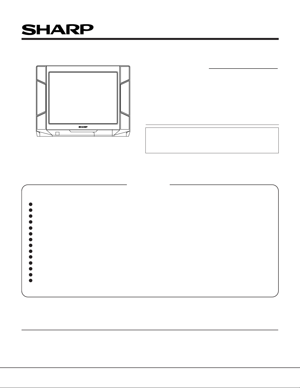
2 Connect the oscilloscope to TP210 as shown
below.
TP210
0.1V
TV SETOscilloscope
Bias Box: About 4.5V
Bias
box
Fig. 3-1
3 Lower the input electric field strength to 51 ±
1dBµV (75Ω Open).
4 Under the conditions 1 and 3, TP210 volt-
age does not vary.
Raise the input signal electric field strength to
60 ± 1dBµV (75Ω Open), and verify that it is
0.1V or more lower than TP210 of 1 and 3.
5 Set the signal at 63 to 67dBµV, and verify that
any noise is not output.
6 Set the signal at 90 to 95dBµV, and verify that
any black letter beat is not output.
Note: If the impedance converter of
50/75 is not used at the electric
field strength meter of 50Ω system, set 52 ± 1dBV for 54 ±
1dBµV (75Ω Open).
Moreover , take care f or the loss
if the converter is used.
* If there is not any problem when the
several lots of the model which employs the relevant tuner is checked,
apply the check of only 5 and 6.
VIDEO LEVEL ADJUSTMENT
NO. Adjustment part Adjusting procedure and conditions Waveform and others
1 VIDEO DET
Level adjustment
R220
1 E-12CH B/G-PAL colour bar (100% white bar)
is received.
2 Adjust R220 to make the video output of the
A V -OUT terminal become 1.0 ± 0.05Vp-p at the
75Ω terminator.
DIGITAL COMB FILTER Y LEVEL ADJUSTMENT
NO. Adjustment part Adjusting procedure and conditions Waveform and others
Digital comb filter
1
Y level adjustment
R5406
1 Input P AL colour bar signal (100% white colour
bar) of 1.0Vp-p at the 75Ω terminator from AVIN terminal.
(Input level 1.0Vp-p ± 0.05Vp-p)
2 Connect the oscilloscope to TP5400.
3 Adjust R5406 to make the Y signal (100% white)
of TP5400 become 2.0 ± 0.1Vp-p.
* V erify that all are linearly amplified. (100% white
area must not be collapsed.)
When it is adjusted at E-12ch, take
care for the voltage value.
8
Page 8
PAL CHROMA ADJUSTMENT
Cy G
75%W Y
100%W
Mg
R
B
(B-Y)
W Y Cy G Mg R B
(B-Y)
W Y Cy G Mg R B
Cy G
WY
100%W Mg R
B
NO. Adjustment part Adjusting procedure and conditions Waveform and others
SUB-COLOUR
1-1
I2C bus adjustment (RF signal)
1-2 * SUB-COLOUR
I2C bus adjustment (DVD
signal)
1 E-12CH(PAL colour bar) is received.
2 Make the image normal with the remote con-
troller.
3 Connect the oscilloscope to TP3802. (10:1
probe is used.)
Range: 2V/Div.
Sweep time : 20µsec/Div.
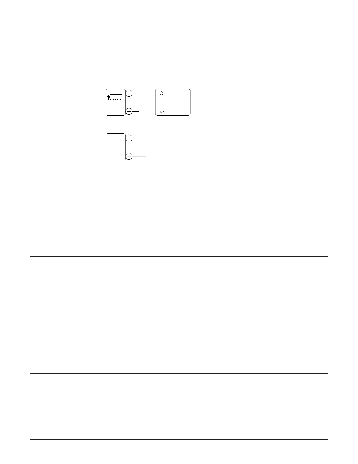
4 Set the sub colour adjustment mode with the
remote controller, and v ary the sub colour data
to make 100%W of the colour bar and RED at
the same level for adjustment shown in Fig. 1-
1.
1 DVD signal is received. (Half colour bar signal)
2 Make the image normal with the remote con-
troller.
3 Connect the oscilloscope to TP3802. (10:1
probe is used.)
Range : 2V/Div.
Sweep time: 20µsec/Div.
4 Set the sub colour adjustment mode (DVD) with
the remote controller, and vary the sub colour
(DVD) data to make 100%W of the colour bar
and RED at the same level for adjustment
shown in Fig. 1-2. (* It is being examined.)
Fig. 1-1
Fig. 1-2
SX68JS10
NTSC CHROMA ADJUSTMENT
NO. Adjustment part Adjusting procedure and conditions Waveform and others
SUB-TINT
1-1
I2C bus adjustment (RF signal)
1-2 * SUB-TINT
I2C bus adjustment (DVD
signal)
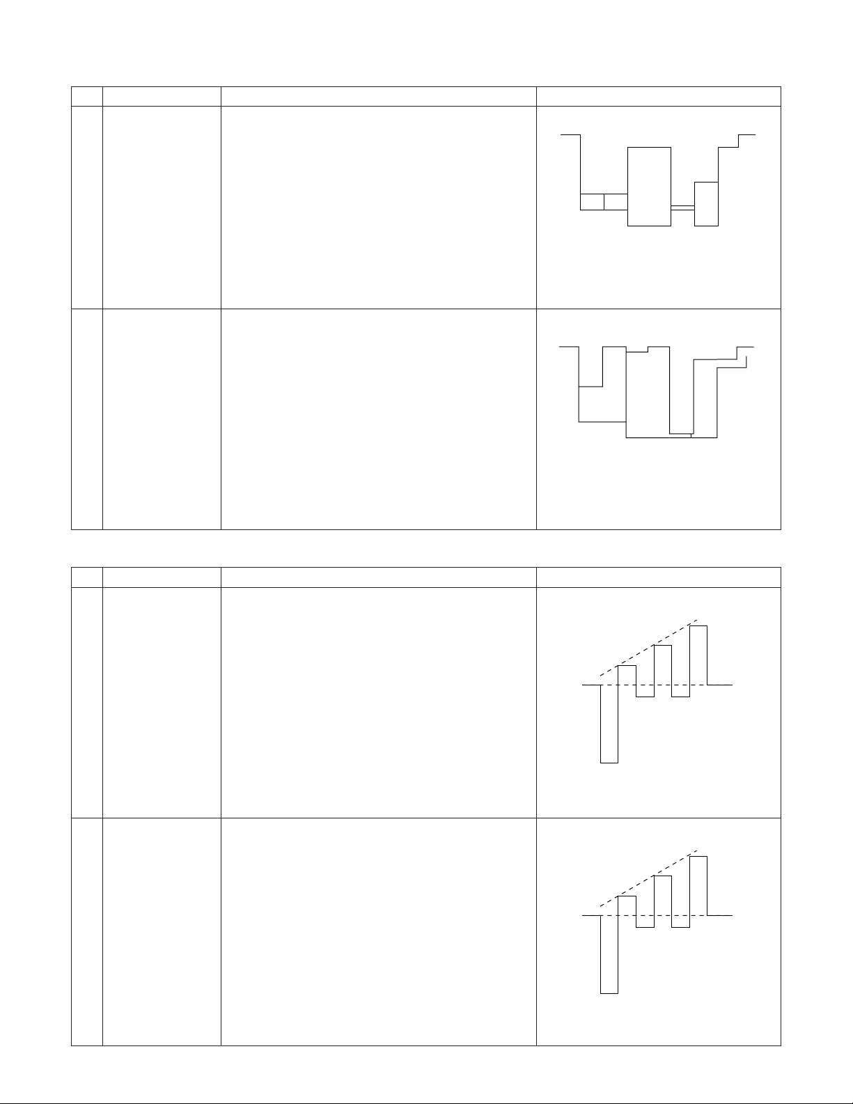
1 Select the sub-tint adjustment mode (automatic
Y cut) to receive JA-8CH(NTSC colour bar).
2 Connect the oscilloscope to TP800 (B-Y).
Range : 20mV/Div. (AC)
Sweep time: 20µsec/Div. (10:1 probe is used.)
3 Vary the sub tint data to adjust the wavef orm to
be gained as shown in Fig. 1-1.
TP3803...........(KY) 6 pin
Fig. 1-1
1 Select the sub-tint adjustment mode (automatic
Y cut) to receive the DVD colour bar signal.
2 Connect the oscilloscope to TP800(B-Y).
Range : 20mV/Div. (AC)
Sweep time: 20µ sec/Div. (10:1 probe is used.).
3 Vary the sub tint data to adjust the wavef orm to
be gained as shown in Fig. 1-1.
4 Release the adjustment mode.
Fig. 1-1
9
Page 9

SX68JS10
SOUND LEVEL ADJUSTMENT
NO. Adjustment part Adjusting procedure and conditions Waveform and others
SUB VOL (Bus
1
adjustment)
1 Receive E-12ch (PAL colour bar). Signal con-
tent: 400Hz 100% Mod.
2 Connect the probe of the meter (*) to (SI) con-
nector.
3 Select SUB-VOL in the service mode.
4 Adjust the SUB-VOL data (At L-ch).
Adjustment value : 11.2 ± 0.3Vr ms
Adjustment value : 11.2 – 0.05Vrms
Note:
* SPATIALIZER OFF
* S-Normal state
* S-VOL Max
* S-BOOSTER OFF
* : Use the multimeter or similar
which sufficiently attenuates the
high-band frequency (bigger than
100kHz).
2 Noise mute
check
1 Receive E-12CH (PAL colour bar).
2 Maximize the sound volume to verify that the
sound is output from the speaker. Then, set
the non-signal state.
3 At this time, verify that the audio mute oper-
ates.
4 After checking the operation, set the sound
volume to be the smallest.
SIF (IGR) ADJUSTMENT
NO. Adjustment part Adjusting procedure and conditions Waveform and others
VCO COIL
1
T2300
1 Receive E-69CH (PAL colour bar).
(Set the receiving frequency at AFT OFF 855.25
MHz.)
2 Connect the digital voltmeter to TP202 (in the
main unit).
3 Verify that it is turned counterclockwise to 0V
and clockwise to 5V, and adjust T2300 to make
the DC voltage of TP202 become 2.5 ± 0.1V in
the range.
* Single-unit adjustment
Vcc 5V ± 0.1V
IF input frequency 38.9MHz ± 10kHz
Control it under these conditions.
Adjust T2300 to mak e the DC voltage of TP2300(in
the NICAM unit) become 2.5 ± 0.1V.
After single-unit adjustment, check the practical
setup.
Align the receiving frequency to the select channel frequency. (AFT OFF)
The checked voltage must be 2.5 V ± 1.0V.
(Take care that ±1.0 is considered for the Vcc difference between the single unit and unit, F o difference and so on, but is not the adjustment precision.)
10
Page 10

CUT OFF, BKGD ADJUSTMENT METHOD
NO. Adjustment part Adjusting procedure and conditions Waveform and others
CRT CUT OFF
1
Service mode
I2C bus data
adjustment
1 Receive E-5CH (Monoscope pattern).
2 Select P-NORM with the remote controller.
3 Turn on the service SW, and select the CUT
OFF BKGD mode.
4 Select the screen VR 0/10.
5 Press “-/--” key of the remote controller to se-
lect the lateral in-line mode.
9 Turn the screen VR clockwise, and adjust the
first lighting lateral in-line raster to slightly light.
0 Adjust the CUT OFF data of two other colours,
and coarsely adjust the lateral in-line to become
white. (Note 1)
q T urn the screen VR in the opposite direction to
the point where the lateral in-line raster goes
out.
Note 1: Apply the adjustment after aging with
the beam current 1500 ± 50µA or
more for 30 minutes or more.
w Press “-/--” key of the remote controller to se-
lect the normal mode.
On the monocolour screen of white
or green
SX68JS10
2-1 White balance
background
I2C bus adjustment
(RF Signal)
1 E-5CH (Monoscope pattern) is received.
2 Select P-NOM with the remote controller.
3 Connect the beam ammeter between TP1601
and TP1602.
4 Coarsely adjust the beam current to approx.
1.7 mA with R1633 (sub-contrast VR).
5 Receive the window pattern with AV input.
(PAL burst is generated with the signal
generator.)
6 With the data of G-drive and B-drive, adjust the
colour temperature 12,300K of the white peak
to white.
7 Adjust the right dark area of the window to
12,300K with R-cut off, G-cut off and B-cut off .
8 Readjust the colour temperature at the white
peak.
9 Check 12,300K at the low white.
Note 1 :Apply this adjustment after aging
with the beam current 1,500 ± 50µA
or more for 30 minutes or more.
(On the white or green monocolour
screen)
Note 1 :
R CUT OFF UP "1" KEY
DOWN "4" KEY
G CUT OFF UP "2" KEY
DOWN "5" KEY
B CUT OFF UP "3" KEY
DOWN "6" KEY
Data up/down is possible with the
above comparison.
* 12300 °K X : 0.272
Y : 0.275
(With Minolta colour thermometer
CA-100)
Note 1 :
G-DRIVE UP "7" KEY
DOWN " " KEY
B-DRIVE UP "8" KEY
DOWN "0" KEY
Data up/down is possible with the
above comparison.
* The colour temperature is based on
the shipment initial setting table.
* White balance
2-2
background
I2C BUS adjustment (DVD
signal)
1 The window pattern is received with DVD sig-
nal (component signal).
2 Apply the adjustment in the same manner as
2-15 and subsequence above. (12,300K)
(G-DRIVE, B-DRIVE, R-CUTOFF, G-CUTOFF, B-CUTOFF)
Apply the adjustment after the end of 2-1.
11
Note 2 : Use the window pattern of
the signal generator for
adjustment.
(PAL and colour burst are present.)
Note 3 : Signal generator of 2-1, 2-2
use
"SX-1006"
Page 11

SX68JS10
SUB CONT SUB-BRIGHT ADJUSTMENT
NO. Adjustment part Adjusting procedure and conditions Waveform and others
MAX BEEM
3
R1633
SUB-CONTRAST
4-1
I2C bus adjustment (RF signal)
1 Receive E-5CH (Monoscope pattern) with
standard mode.
2 Make the image normal with the remote con-
troller.
3 Connect the beam ammeter between TP1601
and TP1602.
Ammeter full scale 3mA range
TP1602 is connected at the - side of the
ammeter.
TP1601 is connected at the + side of the
ammeter.
4 Adjust the beam current to 1.7mA ± 50µA with
R1633 (sub-contrast VR).
Note : Apply the adjustment after aging with the
beam current 1,500 ± 50µA or more for
30 minutes or more.
(On the white or green monocolour
screen)
1 Receive the window pattern with AV input.
2 Make the image normal with the remote con-
troller.
3 Select the SUB-CONTRAST adjustment mode
with the remote controller, and adjust 50% white
to 110 ± 3cd.
Note 1 : Use “Y” of Minolta colour
analyzer CA-100 in adjustment 4-1, 4-2, 5-1, 5-2.
SUB-CONTRAST
4-2
I2C bus adjustment (DVD
signal)
SUB-BRIGHT
5-1
I2C bus adjustment (RF signal)
SUB-BRIGHT
5-2
I2C bus adjustment (DVD
signal)
1 Select the DVD mode.
2 Receive the signal of the DVD signal genera-
tor. (Component signal)
(Window pattern)
3 Make the image normal with the remote con-
troller.
4 Select the SUB-CONTRAST adjustment mode
(DVD) with the remote controller, and adjust
50% white to 110 ± 3cd.
1 Receive the window pattern with AV input.
2 Make the image normal with the remote con-
troller.
3 Select the sub-bright adjustment mode with the
remote controller, and adjust the right dark white
area of the window pattern to 2.7cd ± 0.3cd.
1 Select the DVD mode.
2 Receive the signal of the DVD signal genera-
tor. (Component signal) (Window pattern)
3 Make the image normal with the remote con-
troller.
4 Select the sub-bright adjustment mode (DVD),
and adjust the right dark white area of the window pattern to 2.7cd ± 0.3cd of the window
pattern.
Note 2 : Window pattern of signal
generator is same ad JA12CH.
Note 3 : Use the signal generator
"SX-1006" for SUB-CONT.,
SUB-BRIGHT adjustment.
* When E-2CH (Crosshatch pattern) or
equivalent signal is received.
1 Make the image normal with the
remote controller.
2 Adjust the 3rd (1 thr u 5 from the
left) black of the window pattern to
sink.
CUTOFF POINT
12
Page 12

HORIZONTAL/VERTICAL CIRCUIT ADJUSTMENT
NO. Adjustment part Adjusting procedure and conditions Waveform and others
V-AMPLITUDE 50
1
V-LINEARITY 50Hz
V-SCORRECTION 50Hz
V-RHASE(50)
(V-CENTER)
Adjust the overscan to 8.5% ± 0.5%. (E-5)
Adjust the linearity to the best.
Already preset (**). (Adjust this unless the linearity is achieved.)
Align the center of the screen to the geometric
center of CRT. (E-5)
The receiving channel in ( ) are the
following signals.
(E-2): Crosshatch (50Hz)
(E-5): Monoscope (50Hz)
SX68JS10
H-RHASE(50)
(H-CENTER)
H-SIZE
E/W-PARABOLA
(SIDE-PIN)
V-BIAS
V- ∫CORRECTION
EW-CORNER
(SUB-SIDEPIN)
TRAPEZIUM
V-COMPENSATION
H-COMPENSATION
OTHER
Align the center of the screen to the geometric
center of CRT. (E-5)
Adjust the overscan to 8.5% ± 0.5%. (E-5)
Adjust the 1st vertical line from the left and right
ends of the crosshatch to be straight. (E-2)
Already preset.
Already preset.
Adjust the end of the line of the crosshatch to be
straight.
Already preset. (Adjust if the quality is specially
poor.)
Already preset. (Adjust if the quality is specially
poor.)
Already preset. (Adjust if the quality is specially
poor.)
On the items of V -AMPLITUDE60, V -LINEARITY60,
V-SCORRECTION60, V-RHASE60, H-RHASE60
and H-SIZE60, the compensation data is automatically input if the 50Hz mode adjustment is
done.
However, if it is largely deviated when
it is checked in the 60Hz mode,
readjust it in the 60Hz mode.
2
Focus adjustment
1 Receive E-5CH (crosshatch pattern).
2 With the remote controller, make the image
normal.
3 Adjust the focus VR to make the v ertical line of
"5" in "E-5" display upper left part of screen as
fine as possible.
This vertical line make
as fine as possible.
13
Page 13

SX68JS10
FUNCTION OPERATION CHECK (1) (VIDEO AND AUDIO)
NO. Check item Adjusting procedure and conditions Waveform and others
1
CONTRAST
2
COLOUR
1 Receive E-5CH.
2 In P-mode, select CONTRAST.
3 The contrast must be varied with UP/DOWN.
1 Receive J-13CH.
2 In P-mode, select COLOUR.
3 The colouring must be varied with UP/
DOWN.
(Any colour must not remain in MIN.)
BRIGHTNESS
3
4
TINT
5
NORMAL
SHARPNESS
6
7
CH sign display
colour
1 Receive E-5CH.
2 In P-mode, select BRIGHT.
3 The black level must be varied with UP/
DOWN.
1 Receive NTSC colour bar (AV input)
2 In P-mode, select TINT.
3 With UP/DOWN, the tint must be varied toward
green for UP, and toward red for DOWN.
1 If NORMAL key is pressed when the mode is
displayed in P/S-mode, the displayed content
alone must be set to be normal.
1 Receive E-5CH.
2 In P-mode, select SHARPNESS.
3 The screen quality must be varied with UP/
DOWN.
1 All CH (0 thru 99) sign must be displayed in
green.
TREBLE
8
BASS
9
10 BALANCE
1 Receive E-5CH.
2 In S-mode, select TREBLE.
3 The high band must be varied with UP/DOWN.
1 Receive E-5CH.
2 In S-mode, select BASS.
3 The low band must be varied with UP/DOWN.
1 Receive E-5CH.
2 In S-mode, select BALANCE.
3 Verify that the left/right balance must be varied
with UP/DOWN.
14
Page 14

FUNCTION OPERATION CHECK (2) (VIDEO AND AUDIO)
NO. Check item Adjusting procedure and conditions Waveform and others
11 COLOUR
SYSTEM
1 When receiving the E-12CH PAL colour bar,
check that the colour system can receive in the
PAL mode only and that colour is reproduced
normally.
2 When receiving the NTSC 4.43 colour bar in
the AV input mode and setting the colour system to a mode except AUTO, N4.43, check
that colour is reproduced normally.
3 When receiving the NTSC 3.58 colour bar in
the AV input mode and setting the colour system to a mode except AUTO, N3.58, check
that colour is not reproduced normally.
SX68JS10
SOUND SYS-
12
TEM
13
SPATIALIZER
Key
1 When E-12CH colour bar is received and B/G
is selected in the sound system,
Verify that the sound must not be properly
output.
1 Receive E-5CH music broadcast.
2 The sound mode must be switched with
SPATIALIZER key (R/C) as follows.
SPATIALIZER OFF ↓
SPATIALIZER 1 ↓
SPATIALIZER 2 ↓
3 Verify that the sound from the speaker in the
MONO mode is felt to be wide.
R/C key or MENE screen
14
S-BOOSTER
1 Receive E-5CH music broadcast.
2 Switch S-BOOSTER in S-mode as below.
OFF – 1 – 2 – 3
15
Page 15

SX68JS10
A/V INPUT/OUTPUT CHECK
NO. Check item Adjusting procedure and conditions Waveform and others
Video output
1
check
Audio output
check
1 Receive E-12CH colour bar (colour bar audio
400Hz 100% MOD of 100% white).
2 The video output must be within the specified
range of 1.0Vp-p ± 3dB at the 75Ω terminator.
3 The audio output must be within the specified
range of 1.76Vp-p ± 3dB at the 10kΩ terminator.
Video input
2
check
Audio input
check
S-terminal input
check
3 AV3 automatic
discrimination
check
1 The mode must be switched in the cycle of TV
→ AV1 → AV2 → AV3 → DVD → TV with TV/
A V key of R/C, and the image and voice which
correspond to each input/output terminals must
be properly output.
* Here, DVD is applied for the input alone.
2 When the connector is inserted into the S-video
input terminal on AV1, it must be s witched from
AV to S-video and must be properly operated.
Moreover,
check “AV1-S” of OSD.
3 When the connector is inserted into the S-video
input terminal on AV3, it must be s witched from
AV to S-video and must be properly operated.
Moreover,
check “AV3-S” of OSD.
1 Receive TV with R/C.
2 When the signal is input to the video input ter-
minal of A V3, it is automatically switched to A V3.
3 When the signal is input to the S-video input
terminal of AV3, it is automatically switched to
AV3-S.
* Setting: Auto select in the feature — ON
PROTECTOR OPERATION CHECK
NO. Check item Adjusting procedure and conditions Waveform and others
H, V protector 1 Receive E-5CH (monoscope pattern).
1
2 Connect the bias box to the cathode side
(R1622 side) of D1604.
Reference Approx. 20 V as ordinary
2
Other protectors
3 Set the voltage of the bias box at 16V , and v erify
that the protector does not operate.
4 Set the voltage of the bias box at 24V , and v erify
that the protector operates.
Correspondence for short circuit of
smoothening electrolysis of +B line and so on
To check the operation of the protector and
so on, take care for the breakage, deteriora-
tion and so on of each element.
16
Page 16

A
SX68JS10
No
Yes (RED)
Dose horizontal circuit
momentary oscillate?
NO RASTER
TROUBLE SHOOTING TABLE (Continued)
Does RY1700 turn on?
Yes
Turns on, but soon turns off.
Check CRT connector (KY), (H) bias.
Does D1002 (Power LED) turn on?
Abnormal
Normal
Check R1610,
IC801 and its
peripheral parts.
Check IC3801,
IC3802 and
IC3803.
D1002 (Power LED) turn on and off.
No
Check the
Yes
Check
(Bus error)
power circuit
consisting of
IC700, IC752
and IC600.
protecter circuit
and its related
parts (2) pin of
IC1000 vertical
pulse.
B
See many often
D1002 flashes
in red.
This indicates
which IC to
check up.
Check D1602, R1610 and
L1500.
Abnormal
NO VERTICAL SCAN
Check the voltage at pin (6) of IC1501 and
pin (6) of IC1500.
Check IC801 and its
peripheral parts.
TROUBLE SHOOTING TABLE
Normal Abnormal
Check vertical trigger pulse at pin (31) of IC801.
Normal
Check IC1500, IC1501
and related circuits
17
Page 17
SX68JS10
2000 (ms)500 500
2000 (ms)500 500
2000 (ms)500 500
2000 (ms)500 500
500 500 2000 (ms)
Bus-Err
Bus-Err
PROM
2
E
(IC1001)
V/C/D
TROUBLE SHOOTING TABLE (Continued)
(IC801)
PDC
Bus-Err
(IC1500)
Bus-Err
AV-SW
(IC401)
Bus-Err
SPATIALIZER
(IC300)
Bus-Err
IGR
(IC2300)
2000 (ms)
500 500
Bus-Err
B
500 500
PLL
2000 (ms)
(TU200)
Bus-Err
DCF
500 500
(IC5400)
2000 (ms)
500 500
Bus-Err
4ch DAC
2000 (ms)
(IC1003)
Yes
Blown out
Replace the Fuse.
Check the power circuit
consisting of T700, IC700
etc.
Is the Fuse again blown out?
A
Check F700.
No
Normal
NoYes
Check IC1000,
Does 5V appear at pin (27), (18) of IC1000.
Check the
TROUBLE SHOOTING TABLE (Continued)
18
IC1002, Q1005,
Q1750 and
Q1751.
peripheral circuit
of IC1700,
IC1701, IC1750
and D1752.
Page 18

C
No snow noise.
Abnormal
Check TU200(TUNER)
and its related parts.
Check pin (19) of TU200.
Check IC401 its
Check Q200, Q201, Q203
and their peripheral circuit.
Yes
peripheral circuit.
No
Check IC3801,
IC3802, IC3803
and their peripheral
circuit.
Are pin (8) of IC3801, pin (8) of
IC3802 and pin (8) of IC3803.
Check the
peripheral circuits
of screen heater
(FBT) and the CRT.
Yes
No Yes No
Check IC801 RGB
out Normal?
Yes
Check IC800,
IC802, IC803 and
their peripheral
circuit.
SX68JS10
No
Normal
TROUBLE SHOOTING TABLE (Continued)
Noise or signal
appear.
Is AV1, AV2, AV3 or
DVD input normal?
Check pin (36) of
IC401 noise or signal
appear?
C
No
NO PICTURE
Does the snow noise appear
on the picture tube at max
contrast and brishtness
control?
Check IC753, L203 etc.
Check IC750, L202, TU200
etc.
No
No
Check L201, IC751 etc.
No
Yes
No
Check pin (15) of
IC801 noise or signal
appear?
Check IC400, Q404,
Q410, Q412 and
their peripheral
circuit.
Yes
Snow noise increase.
TROUBLE SHOOTING TABLE (Continued)
Does 9V appear at pin (6) of
TU200 (TUNER).
Yes
Does 33V appear at pin (9) of
TU200.
Yes
Does 5V appear at pin (7) of
TU200.
Check TU200, Q204 etc.
19
Page 19

SX68JS10
D
NoYes
No
No
NO COLOUR
Turn on colour control. Does
colour appeart?
Turn on colour system forced
switch. Does colour appear?
Is chroma input level of IC801
pin (13) proper?
No
Yes
Is only RF signal's colour abnormal?
Check TU200,
NO SPECIFIC COLOUR
Q200, Q201, Q203,
Yes
Set colour
IC401 and their
peripherals.
control.
Yes
Fix cotrol to
coloured
system.
TROUBLE SHOOTING TABLE (Continued)
NTSC3.58:
Check X801, pin
(10) of IC801 and
No
Check IC5400,
Q402 and their
peripherals.
No
Yes
Is SCP signal waveform at pin (2) of
IC801 proper?
Are signal waveforms at pin (26)of
IC800 and pin (27) of IC800
proper?
No
PAL, NTSC4.43:
Check X800, pin
(8) of IC801 and
their peripherals.
their peripherals.
Yes
Is FBP signal waveforms at pin
(25) of IC801 proper?
Yes
Check IC800,
Check D1603
and its
peripherals.
Check IC801.
Yes
Check IC801.
Are waveforms at pins (51) and
(52) of IC801 proper?
No
IC802, IC803 and
their peripherals.
Yes
YesNo
Yes
Is there audio signal at pins (6), (25)
of IC300?
Is audio output terminal J401
normal.
NO NORMAL SOUND
No
TV sound.
Change the sound system.
No
Set S-Volume at
maximum.
Do pins (15), (18)
of IC300 work?
Check IC401
peripheral
parts.
No Yes
Is sound normal?
Is there audio
Check IC300.
YesNo
signal at pins
(5), (6) of
IC401?
Is there audio signal
Check IC302,
Check TU200
and its
TROUBLE SHOOTING TABLE (Continued)
Yes
the sound
system
inpositon.
parts.
Check IC1300,
at pin (9) of IC1300
and IC1301?
No
IC305, IC303, IC304
and their peripheral
circuit.
peripheral
circuits of no
problem, set
Check
TU200
peripheral
IC1301 and their
peripheral parts.
Check IC401
and its
peripheral
circuit.
20
Check IGR
unit peripheral
circuit.
Page 20

SX68JS10
No
Yes
Fix control to coloured system.
Turn on colour system forced
switch. Does colour appear?
Fix control to
No
Check IC801.
coloured system.
No
Check Q402, IC5400,
Yes
Is chroma input level pin (13) of
IC801 proper?
Ref. value: 100 ~ 500mVp-p.
Check IC801
and its
D
Yes No
Colour control circuit detective.
Colour saturation control does not
work.
Turn up and down colour control.
Does colour gain go up and
down?
Can the sub-colour be readjusted
in service mode?
COLOUR PRODUCED
No
White
balance:
Check RGB
output circuit
of IC801.
TROUBLE SHOOTING TABLE (Continued)
Colour in B/W mode.
Yes Yes
SET Sub-
No
and their peripherals.
Yes No
Is SCP signal waveform at pin (2)
of IC801 proper?
Yes
peripherals.
colour.
Are signal waveforms at pin (26) of IC800
and pin (27) of IC800 proper?
Is FBP signal waveform at pin (25)
of IC801 proper?
No
YesNo
Yes
Check D1603
and its
peripherals.
Check IC801.
PAL, NTSC4.43:
Check X800 pin
(8) of IC801 and
their peripherals.
NTSC3.58:
Check X801
pin (10) of
IC801 and their
Check IC801.
peripherals.
Turn colour control to minimum.
Does colour disappear?
APG circuit:
Check IC801
and its
peripherals.
21
Are waveforms at pins (51) and
(52) of IC801 proper?
Check IC800,
IC802, IC803
and their
peripherals.
Page 21

SX68JS10
28 15
SOLID STATE DEVICE BASE DIAGRAM
TOP VIEW
20 11
16 9
30 16
52
27
1 14
VHiTC9090AN-1
1 10
VHiLH64256C-1
1 8
VHiNJM2284M-1
1 15
VHiTA8772AN-1
1
RH-iX3275CEN2
VHiAN7396K/-1
56 29
1 28
RH-iX3323CEZZ VHiTDA9808T-1 VHiTDA9874H-1
16
18
VHiNJM2284M-1
9
22 12
1 11
VHiAN5385K/-1
20 11
1 10
24 13
1 12
VHiTA1229N/-1
VHiTA1241AN-1
VHiMiP0253/-1
48 25
1 24
RH-iX2451CEZZ
RH-DX0083GEZZ
RH-FX0008GEZZ
8 5
1 4
VHiM24C08B/-1
VHiBA7655AF-1
VHiM62334FP-1
42 22
VHiNJM2168M-1
VHiNJM2243M-1
VHiNJM2534M-1
VHiNJM4560M-1
1
VHiTA1218AN-1
21
VHiNJ78L09U-1
VHiNJ78L12U-1
SIDE VIEW
26
EMITTER
COLLECTOR
BASE
VS2SD2581//1E
VS2SD2045//-1
VS2SA1837//-1
VS2SC4793//-1
RH-DX0452CEZZ
1 7
VHiTA8427K/-1
BASE
COLLECTOR
EMITTER
VS2SA1015Y/1E
VS2SC1815GW-1
VS2SC2482//-1
VS2SA1266-Y-1
VS2SC3198Y-1
VS2SA1246//1E
VS2SC1959Y/1E
VHiSTRM6821-1
3
12
VHiSi3051N/-1
VHiKA7809Pi-1
VHiSE120N//-1
SOURCE
GATE
VS2SK583///-1
DRAIN
VHiM51497L/-1
RH-DX0336CEZZ
VHiTDA7482/-1
22
1 15
VHiPST994C/-1
CATHODE
ANODE
GATE
VHSTF861S//-1
RH-iX0037CEZZ
VHiTDA6101Q-1
CATHODE
ANODE
PX0274CE
1 9
RH-iX3232CEZZ
Page 22

WAVEFORMS
SX68JS10
23
Page 23

SX68JS10
CHASSIS LAYOUT
24
Page 24

SX68JS10
25
Page 25

SX68JS10
BLOCK DIAGRAM
MAIN UNIT BLOCK DIAGRAM
26
Page 26

SX68JS10
27
Page 27

SX68JS10
POWER/CRT/IGR UNIT BLOCK DIAGRAM
28
Page 28

SX68JS10
29
Page 29

SX68JS10
DESCRIPTION OF SCHEMATIC DIAGRAM
SAFETY NOTES:
1. DISCONNECT THE AC PLUG FROM THE AC OUTLET BEFORE
REPLACING PARTS.
2. SEMICONDUCTOR HEAT SINKS SHOULD BE REGARDED AS
POTENTIAL SHOCK HAZARDS WHEN THE CHASSIS IS OPERATING.
IMPORTANT SAFETY NOTICE:
PARTS MARKED WITH “å” ( ) ARE IMPORTANT FOR
MAINTAINING THE SAFETY OF THE SET. BE SURE TO REPLACE THESE PARTS WITH SPECIFIED ONES FOR MAINTAINING THE SAFETY AND PERFORMANCE OF THE SET.
SERVICE PRECAUTION:
THE AREA ENCLOSED BY THIS LINE (
CONNECTED WITH AC MAINS VOLTAGE.
WHEN SERVICING THE AREA, CONNECT AN ISOLATING TRANSFORMER BETWEEN TV RECEIVER AND AC LINE TO ELIMINATE
HAZARD OF ELECTRIC SHOCK.
) IS DIRECTLY
NOTES:
1. The unit of resistance “ohm” is omitted.
(K = 1000 ohms, M = Meg ohm).
2. All resistors are 1/16 watt, unless otherwise noted.
3. All capacitors are µF, unless therwise noted. (P = µµF).
VOLTAGE MEASUREMENT CONDITIONS:
1. Voltage in parenthesis measured with no Signal.
2. Voltages without parenthesis measured with PAL Colour-Signal.
3. All the voltages in each point are measured high impedance voltmeter.
WAVEFORM MEASUREMENT CONDITIONS:
1. Colour bar generator signal of 1.5V peak to peak applied at Base
of Video Buffer Amp. Q200.
2. Approximately 4.0 V AGC bias.
30
Page 30
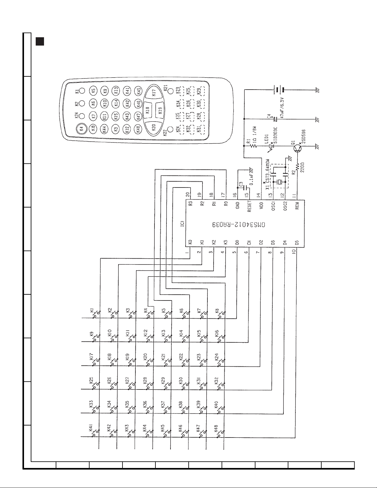
SCHEMATIC DIAGRAM
Infrared Remote Control Unit
SX68JS10
J
I
H
G
F
NOTE: The parts here shown are supplied as an assembly but not independently.
E
D
C
B
Notes
A
Unless specified, the resistors are 1/10W ± 5%.
12345678910
31
Page 31

SX68JS10
Tuner
NOTE: The parts here shown are supplied as an assembly but not independently.
J
I
H
G
(TU200)
å VTUVTBT6ED265
F
E
D
C
B
A
12345678910
32
Page 32

CRT UNIT
J
I
H
G
SX68JS10
F
E
D
C
B
A
12345678910
33
Page 33

SX68JS10
MAIN UNIT(1)
J
I
H
G
F
E
D
C
B
A
12345678910
34
Page 34

SX68JS10
10 11 12 13 14 15 16 17 18 19
35
Page 35

SX68JS10
MAIN UNIT(2)
J
I
H
G
F
E
D
C
B
A
12345678910
36
Page 36

SX68JS10
10 11 12 13 14 15 16 17 18 19
37
Page 37

SX68JS10
POWER UNIT
J
I
H
G
F
E
D
C
B
A
12345678910
38
Page 38

SX68JS10
10 11 12 13 14 15 16 17 18 19
39
Page 39

SX68JS10
IGR UNIT
J
I
H
G
F
E
D
C
B
A
12345678910
40
Page 40

SX68JS10
PRINTED WIRING BOARD ASSEMBLIES
PWB-A: MAIN UNIT (WIRING SIDE)
J
I
H
G
F
E
D
C
B
A
12345678910
42
Page 41

SX68JS10
10 11 12 13 14 15 16 17 18 19
43
Page 42

SX68JS10
PWB-A: MAIN UNIT (WIRING SIDE) (CHIP PARTS)
J
I
H
G
F
E
D
C
B
A
12345678910
44
Page 43

SX68JS10
10 11 12 13 14 15 16 17 18 19
45
Page 44

SX68JS10
PWB-B: POWER UNIT
J
I
H
G
F
E
D
C
B
A
12345678910
46
Page 45

SX68JS10
10 11 12 13 14 15 16 17 18 19
47
Page 46

SX68JS10
J
I
H
G
F
E
D
C
B
PWB-C: CRT UNIT
A
12345678910
48
Page 47

SX68JS10
J
I
H
G
PWB-D: IGR UNIT (WIRING SIDE)
F
E
D
C
B
A
12345678910
PWB-D: IGR UNIT (WIRING SIDE) (CHIP PARTS)
49
Page 48

SX68JS10
Ref. No. Part No. ★ Description Code Ref. No. Part No. ★ Description Code
IC1000 RH-iX3275CEN2 R IX3275CEN2 AZ
REPLACEMENT PARTS LIST
PARTS REPLACEMENT
Replacement parts which have these special safety characteristics
are identified in this manual; electrical components having such
features are identified by "å" in the Replacement Parts Lists.
The use of a substitute replacement part which does not have the
same safety characteristics as the factory recommended replacement parts shown in this service manual may create shock, fire or
other hazards.
"HOW TO ORDER REPLACEMENT PARTS"
To have your order filled promptly and correctly, please furnish the
following informations.
1. MODEL NUMBER 2. REF. NO.
3. PART NO. 4. DESCRIPTION
MARK : SPARE PARTS-DELIVERY SECTION.
Ref. No. Part No. ★ Description Code
PICTURE TUBE
å VB68KYN690X2E A Picture Tube[ITC]
å RCiLG0051PEZZ J ADG Coil AV
LHLDW0003PEKZ J ADG Coil Holder, x 4 AB
LHLDW1075PEKZ J ADG Fix Holder AC
å QEARC2901PEZZ J Grounding Strap AK
PRINTED WIRING BOARD ASSEMBLIES
(NOT REPLACEMENT ITEM)
PWB-A DUNTK9849WEV4 - Main Unit —
PWB-B DUNTK9847WEV5 - Power Unit —
PWB-C DUNTK9848WEV4 - CRT Unit —
PWB-D DUNTK9668WEV6 - IGR Unit —
PWB-A DUNTK9849WEVA MAIN UNIT
TUNER
å TU200 VTUVTBT6ED265 R Tuner BH
INTEGRATED CIRCUITS
IC300 VHiAN7396K/-1 R AN7396K BC
IC301 VHiNJM2168M-1 R NJM2168M AH
IC302 VHiBA7655AF-1 R BA7655AF AG
IC303 RH-iX3232CEZZ R IX3232CE AV
IC304 VHiNJM4560M-1 R NJM4560M AG
IC305 VHiBA7655AF-1 R BA7655AF AG
IC307 VHiTC4066BF1E R TC4066BF AF
IC400 VHiNJM2534M-1 R NJM2534M AF
IC401 VHiTA1218AN-1 R TA1218AN AX
IC402 VHiNJM2243M-1 R NJM2243M AF
IC600 VHiNJ78L09U-1 R NJM78L09U AE
IC601 VHiNJ78L12U-1 R NJM78L12U AE
IC602 VHiM51497L/-1 R M51497L AL
IC800 VHiTA8772AN-1 R TA8772AN AV
IC801 RH-iX3323CEZZ R IX3323CE BB
IC802 VHiAN5385K/-1 R AN5385K AV
IC803 VHiNJM2284M-1 R NJM2284M AF
IC1001 VHiM24C08B/-1 R M24C08B AM
IC1002 VHiPST994C/-1 R PST994C AD
IC1003 VHiM62334FP-1 R M62334FP AH
IC1300 VHiTDA7482/-1 R TDA7482 AR
IC1301 VHiTDA7482/-1 R TDA7482 AR
IC5400 VHiTC9090AN-1 R TC9090AN BC
TRANSISTORS
Q200 VS2SB709A//-1 R 2SB709A AA
Q201 VS2SD601A//-1 R 2SD601A AC
Q202 VS2SD601A//-1 R 2SD601A AC
Q203 VS2SB709A//-1 R 2SB709A AA
Q204 VS2SD601A//-1 R 2SD601A AC
Q302 VS2SD601A//-1 R 2SD601A AC
Q303 VS2SD601A//-1 R 2SD601A AC
Q304 VS2SD601A//-1 R 2SD601A AC
Q305 VS2SD601A//-1 R 2SD601A AC
Q306 VS2SD601A//-1 R 2SD601A AC
Q307 VS2SD601A//-1 R 2SD601A AC
Q308 VS2SD601A//-1 R 2SD601A AC
Q309 VS2SD601A//-1 R 2SD601A AC
Q310 VS2SD601A//-1 R 2SD601A AC
Q311 VS2SD601A//-1 R 2SD601A AC
Q400 VS2SD601A//-1 R 2SD601A AC
Q401 VS2SD601A//-1 R 2SD601A AC
Q402 VS2SD601A//-1 R 2SD601A AC
Q404 VS2SD601A//-1 R 2SD601A AC
Q405 VS2SD601A//-1 R 2SD601A AC
Q406 VS2SB709A//-1 R 2SB709A AA
Q407 VS2SD601A//-1 R 2SD601A AC
Q408 VS2SD601A//-1 R 2SD601A AC
Q409 VS2SD601A//-1 R 2SD601A AC
Q410 VS2SB709A//-1 R 2SB709A AA
Q411 VS2SD601A//-1 R 2SD601A AC
Q413 VS2SB709A//-1 R 2SB709A AA
Q600 VS2SD601A//-1 R 2SD601A AC
Q601 VS2SB709A//-1 R 2SB709A AA
Q800 VS2SD601A//-1 R 2SD601A AC
Q801 VS2SD601A//-1 R 2SD601A AC
Q802 VS2SD601A//-1 R 2SD601A AC
Q803 VS2SB709A//-1 R 2SB709A AA
Q804 VS2SD601A//-1 R 2SD601A AC
Q805 VS2SB709A//-1 R 2SB709A AA
Q806 VS2SD601A//-1 R 2SD601A AC
Q807 VS2SD601A//-1 R 2SD601A AC
Q808 VS2SD601A//-1 R 2SD601A AC
Q809 VS2SD601A//-1 R 2SD601A AC
Q1000 VS2SD601A//-1 R 2SD601A AC
Q1001 VS2SD601A//-1 R 2SD601A AC
Q1002 VS2SD601A//-1 R 2SD601A AC
Q1003 VS2SD601A//-1 R 2SD601A AC
Q1004 VS2SK583///-1 R 2SK583 AE
Q1005 VS2SD601A//-1 R 2SD601A AC
Q1006 VS2SD601A//-1 R 2SD601A AC
Q1007 VS2SD601A//-1 R 2SD601A AC
Q1008 VS2SB709A//-1 R 2SB709A AA
Q1009 VS2SB709A//-1 R 2SB709A AA
Q1010 VS2SB709A//-1 R 2SB709A AA
Q1011 VS2SK583///-1 R 2SK583 AE
Q1301 VS2SD601A//-1 R 2SD601A AC
Q1302 VS2SD601A//-1 R 2SD601A AC
Q1303 VS2SB709A//-1 R 2SB709A AA
Q1304 VS2SD601A//-1 R 2SD601A AC
Q1305 VS2SD601A//-1 R 2SD601A AC
Q1306 VS2SB709A//-1 R 2SB709A AA
Q1307 VS2SD601A//-1 R 2SD601A AC
Q5400 VS2SD601A//-1 R 2SD601A AC
Q5401 VS2SB709A//-1 R 2SB709A AA
Q5402 VS2SD601A//-1 R 2SD601A AC
Q5403 VS2SD601A//-1 R 2SD601A AC
Q5404 VS2SD601A//-1 R 2SD601A AC
Q5405 VS2SB709A//-1 R 2SB709A AA
Q5406 VS2SD601A//-1 R 2SD601A AC
Q5408 VS2SB709A//-1 R 2SB709A AA
Q5409 VS2SD601A//-1 R 2SD601A AC
Q5410 VS2SD601A//-1 R 2SD601A AC
51
Page 49

SX68JS10
Ref. No. Part No. ★ Description Code Ref. No. Part No. ★ Description Code
Q5411 VS2SD601A//-1 R SD601A AC
DIODES AND LED’S
D200 RH-EX0260TAZZ R Zener Diode AC
D201 RH-EX0260TAZZ R Zener Diode AC
D202 RH-EX0260TAZZ R Zener Diode AC
D300 RH-EX0615GEZZ R Zener Diode AA
D301 RH-EX0615GEZZ R Zener Diode AA
D302 RH-DX0475CEZZ R DX0475CE AB
D307 RH-EX0613GEZZ R Zener Diode AA
D308 RH-DX0475CEZZ R DX0475CE AB
D309 RH-DX0475CEZZ R DX0475CE AB
D310 RH-EX0264TAZZ R Zener Diode AC
D400 RH-EX0631GEZZ R Zener Diode AA
D401 RH-EX0264TAZZ R Zener Diode AC
D402 RH-EX0631GEZZ R Zener Diode AA
D405 RH-DX0475CEZZ R DX0475CE AB
D406 RH-EX0628GEZZ R Zener Diode AC
D407 RH-EX0631GEZZ R Zener Diode AA
D408 RH-EX0631GEZZ R Zener Diode AA
D409 RH-EX0631GEZZ R Zener Diode AA
D410 RH-EX0631GEZZ R Zener Diode AA
D411 RH-DX0475CEZZ R DX0475CE AB
D412 VHDDAP202K/-1 R DAP202K AB
D500 RH-DX0475CEZZ R DX0475CE AB
D501 RH-DX0475CEZZ R DX0475CE AB
D502 RH-EX0610GEZZ R Zener Diode AA
D600 RH-DX0475CEZZ R DX0475CE AB
D601 VHDDAP202K/-1 R DAP202K AB
D603 RH-EX0604GEZZ R Zener Diode AB
D604 RH-EX0604GEZZ R Zener Diode AB
D605 RH-DX0475CEZZ R DX0475CE AB
D606 RH-EX0610GEZZ R Zener Diode AA
D607 RH-EX0623GEZZ R Zener Diode AA
D608 RH-DX0475CEZZ R DX0475CE AB
D609 RH-DX0475CEZZ R DX0475CE AB
D800 RH-EX0631GEZZ R Zener Diode AA
D801 RH-EX0631GEZZ R Zener Diode AA
D802 RH-EX0631GEZZ R Zener Diode AA
D803 RH-EX0631GEZZ R Zener Diode AA
D807 RH-EX0631GEZZ R Zener Diode AA
D1000 RH-PX0274CEZZ R LED, Save AC
D1001 RH-PX0274CEZZ R LED, On Timer AC
D1002 RH-PX0414CEZZ R LED, Power On/Off AE
D1003 RH-DX0475CEZZ R DX0475CE AB
D1004 RH-DX0475CEZZ R DX0475CE AB
D1006 RH-EX0260TAZZ R Zener Diode AC
D1007 RH-EX0260TAZZ R Zener Diode AC
D1008 RH-EX0260TAZZ R Zener Diode AC
D1009 RH-EX0260TAZZ R Zener Diode AC
D1012 RH-EX0260TAZZ R Zener Diode AC
D1015 RH-EX0260TAZZ R Zener Diode AC
D1016 RH-EX0260TAZZ R Zener Diode AC
D1017 RH-EX0260TAZZ R Zener Diode AC
D1018 RH-EX0260TAZZ R Zener Diode AC
D1019 RH-EX0260TAZZ R Zener Diode AC
D1020 RH-EX0260TAZZ R Zener Diode AC
D1021 RH-EX0260TAZZ R Zener Diode AC
D1022 RH-EX0260TAZZ R Zener Diode AC
D1023 RH-EX0260TAZZ R Zener Diode AC
D1024 RH-EX0260TAZZ R Zener Diode AC
D1025 RH-EX0260TAZZ R Zener Diode AC
D1026 RH-EX0260TAZZ R Zener Diode AC
D1028 RH-EX0260TAZZ R Zener Diode AC
D1029 RH-EX0260TAZZ R Zener Diode AC
D1030 VHDDAN202K/-1 R DAN202K AB
D1031 RH-EX0260TAZZ R Zener Diode AC
D1032 RH-EX0260TAZZ R Zener Diode AC
D1033 RH-EX0260TAZZ R Zener Diode AC
D1034 RH-EX0260TAZZ R Zener Diode AC
D1304 RH-DX0475CEZZ R DX0475CE AB
D1305 RH-DX0475CEZZ R DX0475CE AB
D1311 RH-EX0260TAZZ R Zener Diode AC
D1312 RH-EX0619GEZZ R Zener Diode AA
D1314 RH-EX0723GEZZ R Zener Diode AB
X800 RCRSB0278CEZZ R Crystal, CRSB0278CE, AG
PACKAGED CIRCUITS
4.43MHz
X801 RCRSB0277CEZZ R Crystal, CRSB0277CE, AG
3.58MHz
FILTERS
CF600 RFiLA0020CEZZ R Filter, 500kHz AD
CF800 RFiLA0034CEZZ R Filter, 503kHz AD
CF1000 RFiLA0084CEZZ R Filter, FiLA0084CE AE
COILS
L200 VP-XF390K0000 R Peaking, 39µHAB
L201 VP-CF270K0000 R Peaking, 27µHAB
L202 VP-CF270K0000 R Peaking, 27µHAB
L203 VP-CF270K0000 R Peaking, 27µHAB
L300 VP-XF101K0000 R Peaking, 100µHAB
L400 VP-DF100K0000 R Peaking, 10µHAB
L401 VP-DF101K0000 R Peaking, 100µHAB
L402 VP-DF101K0000 R Peaking, 100µHAB
L800 VP-DF120K0000 R Peaking, 12µHAB
L801 VP-DF120K0000 R Peaking, 12µHAB
L803 VP-DF101K0000 R Peaking, 100µHAB
L804 VP-DF101K0000 R Peaking, 100µHAB
L805 VP-DF101K0000 R Peaking, 100µHAB
L806 VP-DF101K0000 R Peaking, 100µHAB
L1000 VP-XF1R0K0000 R Peaking, 1µHAB
L1001 VP-DF270K0000 R Peaking, 27µHAB
L1300 RCiLP0016PEZZ R Coil, 47µHAK
L1301 RCiLP0016PEZZ R Coil, 47µHAK
L1302 RCiLP0299CEZZ R Coil, CiLP0299CE AF
L1303 RCiLP0299CEZZ R Coil, CiLP0299CE AF
L1304 RCiLP0299CEZZ R Coil, CiLP0299CE AF
L1305 RCiLP0299CEZZ R Coil, CiLP0299CE AF
L5400 VP-XF330K0000 R Peaking, 33µHAB
L5402 VP-CF101K0000 R Peaking, 100µHAB
L5403 VP-CF101K0000 R Peaking, 100µHAB
L5404 VP-CF101K0000 R Peaking, 100µHAB
L5405 VP-CF101K0000 R Peaking, 100µHAB
L5406 VP-XF470K0000 R Peaking, 47µHAB
L5407 VP-XF470K0000 R Peaking, 47µHAB
L5408 VP-DF101K0000 R Peaking, 100µHAB
L5409 VP-DF101K0000 R Peaking, 100µHAB
L5410 VP-DF101K0000 R Peaking, 100µHAB
L5411 VP-DF101K0000 R Peaking, 100µHAB
L5412 VP-DF101K0000 R Peaking, 100µHAB
L5413 VP-XF270K0000 R Peaking, 27µHAB
L5418 VP-XF330K0000 R Peaking, 33µHAB
T1000 RCiLB0029PEZZ R Oscillation Coil AE
CONTROLS
R220 RVR-M4620GEZZ R Variable Resistor AB
R5406 RVR-M4619GEZZ R Variable Resistor AB
CAPACITORS
C200 VCCCCY1HH150J R 15p 50V Ceramic AA
C201 VCKYCY1HF103Z R 0.01 50V Ceramic AA
C202 VCQYTA1HM222J R 2200p 50V Mylar AA
C203 VCKYCY1HF103Z R 0.01 50V Ceramic AA
C204 VCQYTA1HM102J R 1000p 50V Mylar AA
C206 VCEA0A1CW337M R 330 16V Electrolytic AC
C207 RC-EZ1203CEZZ R 1000 10V Electrolytic AE
C208 VCKYCY1HF103Z R 0.01 50V Ceramic AA
C209 VCKYCY1HF103Z R 0.01 50V Ceramic AA
C210 VCCCCY1HH180J R 18p 50V Ceramic AA
C214 VCEA0A1CW477M R 470 16V Electrolytic AC
C217 VCKYD41HB391K R 390p 50V Ceramic AA
C218 VCKYCY1CB683K R 0.068 16V Ceramic AC
C299 VCEA0A1CW106M R 10 16V Electrolytic AB
C300 VCKYCY1HB102K R 1000p 50V Ceramic AA
C301 VCKYCY1HB102K R 1000p 50V Ceramic AA
C302 VCKYCY1HB102K R 1000p 50V Ceramic AA
C303 VCKYCY1HB102K R 1000p 50V Ceramic AA
C305 VCKYCY1HB102K R 1000p 50V Ceramic AA
C306 VCKYCY1HB102K R 1000p 50V Ceramic AA
C307 VCEA0A1CW106M R 10 16V Electrolytic AB
C308 VCEA0A1CW106M R 10 16V Electrolytic AB
52
Page 50

SX68JS10
Ref. No. Part No. ★ Description Code Ref. No. Part No. ★ Description Code
C309 VCEA0A1CW106M R 10 16V Electrolytic AB
C310 VCEA0A1CW106M R 10 16V Electrolytic AB
C311 VCEA0A1CW106M R 10 16V Electrolytic AB
C312 VCEA0A1CW106M R 10 16V Electrolytic AB
C313 VCEA0A1CW106M R 10 16V Electrolytic AB
C314 VCEA0A1CW106M R 10 16V Electrolytic AB
C315 VCEA0A1CW106M R 10 16V Electrolytic AB
C316 VCE9GA1CW106M R 10 16V Electrolytic AB
C317 VCE9GA1CW106M R 10 16V Electrolytic AB
C318 VCEA0A1CW106M R 10 16V Electrolytic AB
C319 VCEA0A1CW106M R 10 16V Electrolytic AB
C320 VCEA0A1CW106M R 10 16V Electrolytic AB
C321 VCEA0A1CW106M R 10 16V Electrolytic AB
C322 VCKYCY1HB102K R 1000p 50V Ceramic AA
C323 VCKYCY1HB102K R 1000p 50V Ceramic AA
C324 VCQYTA1HM472J R 4700p 50V Mylar AB
C325 VCQYTA1HM472J R 4700p 50V Mylar AB
C326 VCEA0A1CW106M R 10 16V Electrolytic AB
C327 VCEA0A1CW106M R 10 16V Electrolytic AB
C328 VCEA0A1CW106M R 10 16V Electrolytic AB
C329 VCEA0A1CW106M R 10 16V Electrolytic AB
C330 VCEA0A1HW225M R 2.2 50V Electrolytic AB
C331 VCQYTA1HM103J R 0.01 50V Mylar AA
C332 VCEA0A1HW104M R 0.1 50V Electrolytic AB
C333 VCEA0A1CW106M R 10 16V Electrolytic AB
C334 VCEA0A1CW106M R 10 16V Electrolytic AB
C335 VCEA0A1CW106M R 10 16V Electrolytic AB
C336 VCEA0A1CW106M R 10 16V Electrolytic AB
C337 VCQYTA1HM103J R 0.01 50V Mylar AA
C338 VCEA0A1HW104M R 0.1 50V Electrolytic AB
C339 VCFYFA1HA684J R 0.68 50V M.Polypro AD
C340 VCEA0A1CW336M R 33 16V Electrolytic AB
C341 VCEA0A1CW106M R 10 16V Electrolytic AB
C342 VCKYCY1CF104Z R 0.1 16V Ceramic AA
C343 VCEA0A1CW107M R 100 16V Electrolytic AC
C344 VCFYFA1HA104J R 0.1 50V M.Polypro AA
C345 VCQYTA1HM103J R 0.01 50V Mylar AA
C346 VCE9GA1CW226M R 22 16V Electrolytic AB
C347 VCEA0A1CW106M R 10 16V Electrolytic AB
C348 VCEA0A1HW105M R 1 50V Electrolytic AB
C349 VCEA0A1CW106M R 10 16V Electrolytic AB
C350 VCEA0A1CW106M R 10 16V Electrolytic AB
C351 VCEA0A1HW105M R 1 50V Electrolytic AB
C352 VCEA0A1HW105M R 1 50V Electrolytic AB
C353 VCEA0A1CW337M R 330 16V Electrolytic AC
C354 VCEA0A1CW337M R 330 16V Electrolytic AC
C355 VCEA0A1HW105M R 1 50V Electrolytic AB
C356 VCEA0A1CW107M R 100 16V Electrolytic AC
C357 VCEA0A1CW106M R 10 16V Electrolytic AB
C358 VCEA0A1CW106M R 10 16V Electrolytic AB
C359 VCEA0A1CW106M R 10 16V Electrolytic AB
C360 VCEA0A1CW107M R 100 16V Electrolytic AC
C361 VCKYCY1HF103Z R 0.01 50V Ceramic AA
C365 VCKYCY1HB222K R 2200p 50V Ceramic AA
C366 VCKYCY1HB222K R 2200p 50V Ceramic AA
C367 VCEA0A1CW107M R 100 16V Electrolytic AC
C368 VCKYCY1HF103Z R 0.01 50V Ceramic AA
C369 VCEA0A1CW106M R 10 16V Electrolytic AB
C370 VCEA0A1CW106M R 10 16V Electrolytic AB
C372 VCKYCY1HF103Z R 0.01 50V Ceramic AA
C373 VCEA0A1CW106M R 10 16V Electrolytic AB
C374 VCEA0A1CW106M R 10 16V Electrolytic AB
C375 VCKYCY1HF103Z R 0.01 50V Ceramic AA
C376 VCEA0A1CW106M R 10 16V Electrolytic AB
C377 VCEA0A1CW106M R 10 16V Electrolytic AB
C378 VCKYCY1CF104Z R 0.1 16V Ceramic AA
C379 VCEA0A1CW107M R 100 16V Electrolytic AC
C380 VCKYCY1CF104Z R 0.1 16V Ceramic AA
C381 VCKYCY1HB152K R 1500p 50V Ceramic AA
C382 VCKYCY1HB152K R 1500p 50V Ceramic AA
C383 VCKYCY1HB152K R 1500p 50V Ceramic AA
C384 VCKYCY1HB152K R 1500p 50V Ceramic AA
C385 VCKYCY1HF103Z R 0.01 50V Ceramic AA
C386 VCKYCY1HF103Z R 0.01 50V Ceramic AA
C387 VCKYCY1HF103Z R 0.01 50V Ceramic AA
C388 VCEA0A1CW107M R 100 16V Electrolytic AC
C390 VCEA0A1CW476M R 47 16V Electrolytic AB
C391 VCEA0A1CW107M R 100 16V Electrolytic AC
C392 VCKYCY1HF103Z R 0.01 50V Ceramic AA
C393 VCEA0A1CW106M R 10 16V Electrolytic AB
C394 VCEA0A1CW106M R 10 16V Electrolytic AB
C397 VCEA0A1CW106M R 10 16V Electrolytic AB
C398 VCEA0A1CW106M R 10 16V Electrolytic AB
C399 VCKYCY1HF103Z R 0.01 50V Ceramic AA
C400 VCEA0A1CW106M R 10 16V Electrolytic AB
C401 VCKYCY1HF103Z R 0.01 50V Ceramic AA
C402 VCKYCY1HF103Z R 0.01 50V Ceramic AA
C403 VCEA0A1CW106M R 10 16V Electrolytic AB
C404 VCEA0A1CW106M R 10 16V Electrolytic AB
C405 VCFYFA1HA104J R 0.1 50V M.Polypro AA
C406 VCEA0A1CW108M R 1000 16V Electrolytic AD
C407 VCKYCY1HF103Z R 0.01 50V Ceramic AA
C408 VCEA0A1CW106M R 10 16V Electrolytic AB
C409 VCEA0A1CW108M R 1000 16V Electrolytic AD
C410 VCEA0A1CW477M R 470 16V Electrolytic AC
C411 VCEA0A1CW106M R 10 16V Electrolytic AB
C412 VCEA0A1CW106M R 10 16V Electrolytic AB
C413 VCEA0A1CW106M R 10 16V Electrolytic AB
C414 VCKYCY1HF103Z R 0.01 50V Ceramic AA
C416 VCEA0A1CW106M R 10 16V Electrolytic AB
C417 VCEA0A1CW107M R 100 16V Electrolytic AC
C418 VCEA0A1CW106M R 10 16V Electrolytic AB
C424 VCKYCY1CF104Z R 0.1 16V Ceramic AA
C425 VCKYCY1CF104Z R 0.1 16V Ceramic AA
C426 VCKYCY1CF104Z R 0.1 16V Ceramic AA
C428 VCEA0A1CW226M R 22 16V Electrolytic AB
C429 VCFYFA1HA334J R 0.33 50V M.Polypro AB
C430 VCKYCY1HF103Z R 0.01 50V Ceramic AA
C431 VCEA0A1HW105M R 1 50V Electrolytic AB
C432 VCFYFA1HA104J R 0.1 50V M.Polypro AA
C433 VCE9GA1CW106M R 10 16V Electrolytic AB
C434 VCEA0A1CW106M R 10 16V Electrolytic AB
C435 VCEA0A1CW106M R 10 16V Electrolytic AB
C436 VCEA0A1CW106M R 10 16V Electrolytic AB
C437 VCKYCY1EB822K R 8200p 25V Ceramic AA
C438 VCKYCY1HF103Z R 0.01 50V Ceramic AA
C439 VCCCCY1EH561J R 560p 25V Ceramic AA
C440 VCKYCY1HF103Z R 0.01 50V Ceramic AA
C441 VCKYCY1CB104K R 0.1 16V Ceramic AB
C442 VCKYCY1CB104K R 0.1 16V Ceramic AB
C443 VCEA0A1HW225M R 2.2 50V Electrolytic AB
C444 VCEA0A1HW105M R 1 50V Electrolytic AB
C445 RC-EZ1217CEZZ R 470 16V Electrolytic AD
C446 VCEA0A1CW476M R 47 16V Electrolytic AB
C447 VCKYCY1CB104K R 0.1 16V Ceramic AB
C451 VCKYCY1CB104K R 0.1 16V Ceramic AB
C452 VCKYCY1CF104Z R 0.1 16V Ceramic AA
C453 VCKYCY1CF104Z R 0.1 16V Ceramic AA
C455 VCEA0A1AW227M R 220 10V Electrolytic AB
C600 VCKYCY1CF334Z R 0.33 16V Ceramic AA
C601 VCKYCY1CB104K R 0.1 16V Ceramic AB
C602 VCQYTA1HM223J R 0.022 50V Mylar AA
C603 VCEA0A1HW225M R 2.2 50V Electrolytic AB
C604 VCEA0A1HW225M R 2.2 50V Electrolytic AB
C605 VCKYCY1CF334Z R 0.33 16V Ceramic AA
C606 VCKYCY1CB104K R 0.1 16V Ceramic AB
C607 VCEA0A1EW476M R 47 25V Electrolytic AB
C608 VCEA0A1CW476M R 47 16V Electrolytic AB
C609 VCEA0A1EW476M R 47 25V Electrolytic AB
C610 VCEA0A1CW476M R 47 16V Electrolytic AB
C611 VCEA0A1HW224M R 0.22 50V Electrolytic AB
C612 VCKYCY1HF103Z R 0.01 50V Ceramic AA
C613 VCEA0A1CW476M R 47 16V Electrolytic AB
C614 VCKYCY1CF104Z R 0.1 16V Ceramic AA
C615 VCKYCY1HB182K R 1800p 50V Ceramic AA
C616 VCKYCY1HB102K R 1000p 50V Ceramic AA
C617 VCEA0A1CW106M R 10 16V Electrolytic AB
C618 VCEA0A1HW224M R 0.22 50V Electrolytic AB
C800 VCEA0A1HW225M R 2.2 50V Electrolytic AB
C801 VCKYCY1CB104K R 0.1 16V Ceramic AB
C802 VCKYCY1CB104K R 0.1 16V Ceramic AB
C803 VCKYCY1CB104K R 0.1 16V Ceramic AB
C804 VCKYCY1CF474Z R 0.47 16V Ceramic AB
C805 VCKYCY1CF474Z R 0.47 16V Ceramic AB
C806 VCEA0A1HW105M R 1 50V Electrolytic AB
C807 VCEA0A1HW225M R 2.2 50V Electrolytic AB
53
Page 51

SX68JS10
Ref. No. Part No. ★ Description Code Ref. No. Part No. ★ Description Code
C808 VCEA0A1HW225M R 2.2 50V Electrolytic AB
C809 RC-EZ1217CEZZ R 470 16V Electrolytic AD
C810 VCKYCY1HF103Z R 0.01 50V Ceramic AA
C811 VCEA0A1HW474M R 0.47 50V Electrolytic AB
C812 VCEA0A1CW106M R 10 16V Electrolytic AB
C813 VCKYCY1CB104K R 0.1 16V Ceramic AB
C814 VCKYCY1CB104K R 0.1 16V Ceramic AB
C815 VCKYCY1CB104K R 0.1 16V Ceramic AB
C816 VCKYCY1HF103Z R 0.01 50V Ceramic AA
C817 VCEA0A1CW477M R 470 16V Electrolytic AC
C818 VCKYCY1CB104K R 0.1 16V Ceramic AB
C819 VCEA0A1HW474M R 0.47 50V Electrolytic AB
C820 VCEA0A1HW474M R 0.47 50V Electrolytic AB
C821 VCKYCY1CB104K R 0.1 16V Ceramic AB
C822 VCKYCY1HF103Z R 0.01 50V Ceramic AA
C823 VCKYCY1HF103Z R 0.01 50V Ceramic AA
C824 RC-EZ1203CEZZ R 1000 10V Electrolytic AE
C825 VCEA0A1HW224M R 0.22 50V Electrolytic AB
C826 VCQYTA1HM222J R 2200p 50V Mylar AA
C827 VCCCCY1HH120J R 12p 50V Ceramic AA
C828 VCCCCY1HH100D R 10p 50V Ceramic AA
C829 VCKYCY1HF103Z R 0.01 50V Ceramic AA
C830 VCKYCY1CB104K R 0.1 16V Ceramic AB
C831 VCEA0A1HW225M R 2.2 50V Electrolytic AB
C832 VCFYFA1HA104J R 0.1 50V M.Polypro AA
C833 VCFYFA1HA104J R 0.1 50V M.Polypro AA
C834 VCFYFA1HA104J R 0.1 50V M.Polypro AA
C835 VCKYCY1HF103Z R 0.01 50V Ceramic AA
C836 RC-EZ1217CEZZ R 470 16V Electrolytic AD
C840 VCKYCY1HF103Z R 0.01 50V Ceramic AA
C841 RC-EZ1217CEZZ R 470 16V Electrolytic AD
C845 VCKYCY1CF104Z R 0.1 16V Ceramic AA
C846 VCKYCY1CF104Z R 0.1 16V Ceramic AA
C848 VCKYCY1CB104K R 0.1 16V Ceramic AB
C849 VCKYCY1CF104Z R 0.1 16V Ceramic AA
C851 VCKYCY1HF103Z R 0.01 50V Ceramic AA
C852 VCKYCY1HF103Z R 0.01 50V Ceramic AA
C854 VCKYCY1HF103Z R 0.01 50V Ceramic AA
C855 VCE9GA1HW335M R 3.3 50V Electrolytic AB
C856 VCKYCY1HF103Z R 0.01 50V Ceramic AA
C857 RC-EZ1217CEZZ R 470 16V Electrolytic AD
C858 VCEA0A1CW106M R 10 16V Electrolytic AB
C859 VCE9GA1HW335M R 3.3 50V Electrolytic AB
C860 VCKYCY1CF104Z R 0.1 16V Ceramic AA
C861 VCEA0A1CW226M R 22 16V Electrolytic AB
C862 VCEA0A1CW106M R 10 16V Electrolytic AB
C863 VCEA0A1CW106M R 10 16V Electrolytic AB
C864 VCEA0A1CW106M R 10 16V Electrolytic AB
C865 VCKYCY1HF103Z R 0.01 50V Ceramic AA
C867 VCEA0A1AW227M R 220 10V Electrolytic AB
C868 VCKYCY1CF104Z R 0.1 16V Ceramic AA
C869 VCEA0A1CW106M R 10 16V Electrolytic AB
C870 VCEA0A1CW106M R 10 16V Electrolytic AB
C871 VCKYCY1HF103Z R 0.01 50V Ceramic AA
C872 VCEA0A1CW106M R 10 16V Electrolytic AB
C873 VCEA0A1CW106M R 10 16V Electrolytic AB
C874 VCKYCY1HF103Z R 0.01 50V Ceramic AA
C875 VCKYCY1CB104K R 0.1 16V Ceramic AB
C877 VCCCCY1HH1R0C R 1p 50V Ceramic AA
C878 VCCCCY1HH470J R 47p 50V Ceramic AA
C879 VCCCCY1HH470J R 47p 50V Ceramic AA
C880 VCCCCY1HH470J R 47p 50V Ceramic AA
C881 VCEA0A1HW105M R 1 50V Electrolytic AB
C1000 VCCCCY1HH560J R 56p 50V Ceramic AA
C1001 VCCCCY1HH560J R 56p 50V Ceramic AA
C1002 VCKYCY1HF103Z R 0.01 50V Ceramic AA
C1003 VCKYCY1HF103Z R 0.01 50V Ceramic AA
C1007 VCEA0A0JW476M R 47 6.3V Electrolytic AB
C1008 VCKYCY1HF103Z R 0.01 50V Ceramic AA
C1009 VCKYCY1HF103Z R 0.01 50V Ceramic AA
C1010 VCKYCY1HF103Z R 0.01 50V Ceramic AA
C1011 VCKYCY1HF103Z R 0.01 50V Ceramic AA
C1012 VCKYCY1HF103Z R 0.01 50V Ceramic AA
C1013 VCCCCY1HH220J R 22p 50V Ceramic AA
C1014 VCCCCY1HH220J R 22p 50V Ceramic AA
C1015 VCCCCY1HH220J R 22p 50V Ceramic AA
C1016 VCCCCY1HH220J R 22p 50V Ceramic AA
C1017 VCKYCY1HF103Z R 0.01 50V Ceramic AA
C1018 VCKYCY1HF103Z R 0.01 50V Ceramic AA
C1019 VCEA0A1HW105M R 1 50V Electrolytic AB
C1020 VCKYCY1HF103Z R 0.01 50V Ceramic AA
C1021 VCEA0A0JW107M R 100 6.3V Electrolytic AB
C1023 VCKYCY1HF103Z R 0.01 50V Ceramic AA
C1024 VCEA0A0JW476M R 47 6.3V Electrolytic AB
C1025 VCKYCY1HF103Z R 0.01 50V Ceramic AA
C1027 VCEA0A0JW107M R 100 6.3V Electrolytic AB
C1028 VCKYCY1HF103Z R 0.01 50V Ceramic AA
C1029 VCKYCY1HB221K R 220p 50V Ceramic AA
C1030 VCEA0A1HW105M R 1 50V Electrolytic AB
C1033 VCEA0A0JW477M R 470 6.3V Electrolytic AC
C1034 VCKYCY1HF103Z R 0.01 50V Ceramic AA
C1035 VCEA0A1CW107M R 100 16V Electrolytic AC
C1036 VCKYCY1HF103Z R 0.01 50V Ceramic AA
C1037 VCKYCY1HF103Z R 0.01 50V Ceramic AA
C1300 VCFYFA1HA474J R 0.47 50V M.Polypro AC
C1301 VCFYFA1HA474J R 0.47 50V M.Polypro AC
C1302 VCKYPA1HB561K R 560p 50V Ceramic AA
C1303 VCKYPA1HB561K R 560p 50V Ceramic AA
C1304 VCFYFA1HA104J R 0.1 50V M.Polypro AA
C1305 VCFYFA1HA104J R 0.1 50V M.Polypro AA
C1306 VCKYCY1HB472K R 4700p 50V Ceramic AA
C1307 VCKYCY1HB472K R 4700p 50V Ceramic AA
C1308 VCCCCY1HH271J R 270p 50V Ceramic AA
C1309 VCCCCY1HH271J R 270p 50V Ceramic AA
C1310 VCEA0H1VW228M R 2200 35V Electrolytic AH
C1311 VCEA0H1VW228M R 2200 35V Electrolytic AH
C1312 VCEA0H1VW228M R 2200 35V Electrolytic AH
C1313 VCEA0H1VW228M R 2200 35V Electrolytic AH
C1314 VCFYFA1HA104J R 0.1 50V M.Polypro AA
C1315 VCFYFA1HA104J R 0.1 50V M.Polypro AA
C1316 VCFYFA1HA104J R 0.1 50V M.Polypro AA
C1317 VCFYFA1HA104J R 0.1 50V M.Polypro AA
C1318 VCEA0A1HW225M R 2.2 50V Electrolytic AB
C1319 VCEA0A1HW225M R 2.2 50V Electrolytic AB
C1320 VCKYCY1HB102K R 1000p 50V Ceramic AA
C1321 VCKYCY1HB102K R 1000p 50V Ceramic AA
C1322 VCFYFA1HA334J R 0.33 50V M.Polypro AB
C1323 VCFYFA1HA334J R 0.33 50V M.Polypro AB
C1324 VCQYTA1HM822J R 8200p 50V Mylar AA
C1325 VCQYTA1HM822J R 8200p 50V Mylar AA
C1326 VCFYFA1HA104J R 0.1 50V M.Polypro AA
C1327 VCFYFA1HA104J R 0.1 50V M.Polypro AA
C1328 VCFYFA1HA104J R 0.1 50V M.Polypro AA
C1329 VCFYFA1HA104J R 0.1 50V M.Polypro AA
C1330 VCE9GA1CW106M R 10 16V Electrolytic AB
C1332 VCEA0A1CW337M R 330 16V Electrolytic AC
C1333 VCFYFA1HA154J R 0.15 50V M.Polypro AC
C1337 VCKYPA1HF103Z R 0.01 50V Ceramic AA
C1338 VCKYPA1HF103Z R 0.01 50V Ceramic AA
C1340 VCFYFA1HA154J R 0.15 50V M.Polypro AC
C1341 VCEA0A1CW106M R 10 16V Electrolytic AB
C1342 VCEA0A1CW108M R 1000 16V Electrolytic AD
C5401 VCCCCY1HH150J R 15p 50V Ceramic AA
C5402 VCCCCY1HH560J R 56p 50V Ceramic AA
C5403 VCCCCY1HH150J R 15p 50V Ceramic AA
C5404 VCEA0A1HW106M R 10 50V Electrolytic AB
C5405 VCEA0A1CW106M R 10 16V Electrolytic AB
C5406 VCKYCY1HF103Z R 0.01 50V Ceramic AA
C5407 VCEA0A1HW474M R 0.47 50V Electrolytic AB
C5408 VCEA0A1HW106M R 10 50V Electrolytic AB
C5409 VCKYCY1HF103Z R 0.01 50V Ceramic AA
C5410 VCKYCY1HF103Z R 0.01 50V Ceramic AA
C5411 VCEA0A1CW106M R 10 16V Electrolytic AB
C5412 VCKYCY1HF103Z R 0.01 50V Ceramic AA
C5413 VCEA0A0JW477M R 470 6.3V Electrolytic AC
C5414 VCEA0A0JW477M R 470 6.3V Electrolytic AC
C5415 VCKYCY1HF103Z R 0.01 50V Ceramic AA
C5416 VCKYCY1HF103Z R 0.01 50V Ceramic AA
C5417 VCCCCY1HH181J R 180p 50V Ceramic AA
C5418 VCKYCY1HF103Z R 0.01 50V Ceramic AA
C5419 VCKYCY1HF103Z R 0.01 50V Ceramic AA
C5420 VCKYCY1HF103Z R 0.01 50V Ceramic AA
C5421 VCKYCY1HF103Z R 0.01 50V Ceramic AA
C5422 VCEA0A0JW477M R 470 6.3V Electrolytic AC
C5423 VCKYCY1HF103Z R 0.01 50V Ceramic AA
C5424 VCCCCY1HH560J R 56p 50V Ceramic AA
54
Page 52

SX68JS10
Ref. No. Part No. ★ Description Code Ref. No. Part No. ★ Description Code
C5425 VCCCCY1HH220J R 22p 50V Ceramic AA
C5426 VCCCCY1HH220J R 22p 50V Ceramic AA
C5427 VCEA0A1CW106M R 10 16V Electrolytic AB
C5428 VCEA0A1HW106M R 10 50V Electrolytic AB
C5429 VCKYCY1HF103Z R 0.01 50V Ceramic AA
C5430 VCKYCY1HF103Z R 0.01 50V Ceramic AA
C5431 VCKYCY1HF103Z R 0.01 50V Ceramic AA
C5432 VCKYCY1HF103Z R 0.01 50V Ceramic AA
C5433 VCEA0A0JW477M R 470 6.3V Electrolytic AC
C5434 VCKYCY1HF103Z R 0.01 50V Ceramic AA
C5435 VCEA0A1CW107M R 100 16V Electrolytic AC
C5436 VCCCCY1HH121J R 120p 50V Ceramic AA
C5437 VCCCCY1HH120J R 12p 50V Ceramic AA
C5438 VCKYCY1HF103Z R 0.01 50V Ceramic AA
C5439 VCCCCY1HH390J R 39p 50V Ceramic AA
C5440 VCKYCY1HF103Z R 0.01 50V Ceramic AA
C5441 VCEA0A1CW106M R 10 16V Electrolytic AB
RESISTORS
R1 VRS-CY1JF000J R 0 1/16W Metal Oxide AA
R2 VRS-CY1JF000J R 0 1/16W Metal Oxide AA
R11 VRS-CY1JF000J R 0 1/16W Metal Oxide AA
R12 VRS-CY1JF000J R 0 1/16W Metal Oxide AA
R13 VRS-CY1JF000J R 0 1/16W Metal Oxide AA
R14 VRS-CY1JF000J R 0 1/16W Metal Oxide AA
R15 VRS-CY1JF000J R 0 1/16W Metal Oxide AA
R16 VRS-CY1JF000J R 0 1/16W Metal Oxide AA
R17 VRS-CY1JF000J R 0 1/16W Metal Oxide AA
R18 VRS-CY1JF000J R 0 1/16W Metal Oxide AA
R19 VRS-CY1JF000J R 0 1/16W Metal Oxide AA
R20 VRS-CY1JF000J R 0 1/16W Metal Oxide AA
R21 VRS-CY1JF000J R 0 1/16W Metal Oxide AA
R22 VRS-CY1JF000J R 0 1/16W Metal Oxide AA
R23 VRS-CY1JF000J R 0 1/16W Metal Oxide AA
R24 VRS-CY1JF000J R 0 1/16W Metal Oxide AA
R25 VRS-CY1JF000J R 0 1/16W Metal Oxide AA
R26 VRS-CY1JF000J R 0 1/16W Metal Oxide AA
R27 VRS-CY1JF000J R 0 1/16W Metal Oxide AA
R28 VRS-CY1JF000J R 0 1/16W Metal Oxide AA
R29 VRS-CY1JF000J R 0 1/16W Metal Oxide AA
R30 VRS-CY1JF000J R 0 1/16W Metal Oxide AA
R31 VRS-CY1JF000J R 0 1/16W Metal Oxide AA
R32 VRS-CY1JF000J R 0 1/16W Metal Oxide AA
R33 VRS-CY1JF000J R 0 1/16W Metal Oxide AA
R35 VRS-CY1JF000J R 0 1/16W Metal Oxide AA
R38 VRS-CY1JF000J R 0 1/16W Metal Oxide AA
R39 VRS-CY1JF000J R 0 1/16W Metal Oxide AA
R43 VRS-CY1JF000J R 0 1/16W Metal Oxide AA
R46 VRS-CY1JF000J R 0 1/16W Metal Oxide AA
R50 VRS-CY1JF000J R 0 1/16W Metal Oxide AA
R51 VRS-CY1JF000J R 0 1/16W Metal Oxide AA
R52 VRS-CY1JF000J R 0 1/16W Metal Oxide AA
R54 VRS-CY1JF000J R 0 1/16W Metal Oxide AA
R55 VRS-CY1JF000J R 0 1/16W Metal Oxide AA
R56 VRS-CY1JF000J R 0 1/16W Metal Oxide AA
R58 VRS-CY1JF000J R 0 1/16W Metal Oxide AA
R61 VRS-CY1JF000J R 0 1/16W Metal Oxide AA
R62 VRS-CY1JF000J R 0 1/16W Metal Oxide AA
R71 VRS-CY1JF000J R 0 1/16W Metal Oxide AA
R72 VRS-CY1JF000J R 0 1/16W Metal Oxide AA
R73 VRS-CY1JF000J R 0 1/16W Metal Oxide AA
R74 VRS-CY1JF000J R 0 1/16W Metal Oxide AA
R75 VRS-CY1JF000J R 0 1/16W Metal Oxide AA
R76 VRS-CY1JF000J R 0 1/16W Metal Oxide AA
R77 VRS-CY1JF000J R 0 1/16W Metal Oxide AA
R78 VRS-CY1JF000J R 0 1/16W Metal Oxide AA
R79 VRS-CY1JF000J R 0 1/16W Metal Oxide AA
R81 VRS-CY1JF000J R 0 1/16W Metal Oxide AA
R82 VRS-CY1JF000J R 0 1/16W Metal Oxide AA
R83 VRS-CY1JF000J R 0 1/16W Metal Oxide AA
R84 VRS-CY1JF000J R 0 1/16W Metal Oxide AA
R85 VRS-CY1JF000J R 0 1/16W Metal Oxide AA
R86 VRS-CY1JF000J R 0 1/16W Metal Oxide AA
R88 VRS-CY1JF000J R 0 1/16W Metal Oxide AA
R89 VRS-CY1JF000J R 0 1/16W Metal Oxide AA
R200 VRD-RA2BE472J R 4.7k 1/8W Carbon AA
R202 VRS-CY1JF102J R 1k 1/16W Metal Oxide AA
R203 VRS-CY1JF472J R 4.7k 1/16W Metal Oxide AA
R204 VRS-CY1JF123J R 12k 1/16W Metal Oxide AA
R205 VRS-CY1JF472J R 4.7k 1/16W Metal Oxide AA
R206 VRS-CY1JF101J R 100 1/16W Metal Oxide AA
R207 VRD-RA2BE472J R 4.7k 1/8W Carbon AA
R208 VRS-CY1JF101J R 100 1/16W Metal Oxide AA
R209 VRS-CY1JF101J R 100 1/16W Metal Oxide AA
R210 VRS-CY1JF222J R 2.2k 1/16W Metal Oxide AA
R212 VRS-CY1JF101J R 100 1/16W Metal Oxide AA
R213 VRS-CY1JF680J R 68 1/16W Metal Oxide AA
R214 VRS-CY1JF680J R 68 1/16W Metal Oxide AA
R215 VRD-RA2BE391J R 390 1/8W Carbon AA
R216 VRS-CY1JF391J R 390 1/16W Metal Oxide AA
R217 VRS-CY1JF221J R 220 1/16W Metal Oxide AA
R218 VRD-RA2BE473J R 47k 1/8W Carbon AA
R219 VRS-CY1JF473J R 47k 1/16W Metal Oxide AA
R221 VRD-RA2BE331J R 330 1/8W Carbon AA
R222 VRD-RA2BE103J R 10k 1/8W Carbon AA
R223 VRD-RA2BE103J R 10k 1/8W Carbon AA
R226 VRD-RA2EE100J R 10 1/4W Carbon AA
R300 VRD-RA2BE102J R 1k 1/8W Carbon AA
R301 VRS-CY1JF102J R 1k 1/16W Metal Oxide AA
R302 VRD-RA2BE102J R 1k 1/8W Carbon AA
R303 VRS-CY1JF564J R 560k 1/16W Metal Oxide AA
R304 VRD-RA2BE102J R 1k 1/8W Carbon AA
R305 VRS-CY1JF564J R 560k 1/16W Metal Oxide AA
R306 VRS-CY1JF101J R 100 1/16W Metal Oxide AA
R307 VRS-CY1JF101J R 100 1/16W Metal Oxide AA
R308 VRD-RA2BE101J R 100 1/8W Carbon AB
R309 VRD-RA2BE101J R 100 1/8W Carbon AB
R310 VRS-CY1JF101J R 100 1/16W Metal Oxide AA
R311 VRS-CY1JF101J R 100 1/16W Metal Oxide AA
R312 VRD-RA2BE101J R 100 1/8W Carbon AB
R313 VRD-RA2BE101J R 100 1/8W Carbon AB
R315 VRS-CY1JF101J R 100 1/16W Metal Oxide AA
R316 VRS-CY1JF101J R 100 1/16W Metal Oxide AA
R317 VRS-CY1JF104J R 100k 1/16W Metal Oxide AA
R318 VRS-CY1JF561J R 560 1/16W Metal Oxide AA
R319 VRS-CY1JF104J R 100k 1/16W Metal Oxide AA
R320 VRS-CY1JF473J R 47k 1/16W Metal Oxide AA
R321 VRS-CY1JF103J R 10k 1/16W Metal Oxide AA
R322 VRS-CY1JF103J R 10k 1/16W Metal Oxide AA
R323 VRS-CY1JF473J R 47k 1/16W Metal Oxide AA
R324 VRD-RA2BE102J R 1k 1/8W Carbon AA
R325 VRS-CY1JF564J R 560k 1/16W Metal Oxide AA
R326 VRD-RA2BE102J R 1k 1/8W Carbon AA
R327 VRS-CY1JF564J R 560k 1/16W Metal Oxide AA
R328 VRD-RA2BE101J R 100 1/8W Carbon AB
R329 VRD-RA2BE101J R 100 1/8W Carbon AB
R330 VRS-CY1JF102J R 1k 1/16W Metal Oxide AA
R331 VRS-CY1JF102J R 1k 1/16W Metal Oxide AA
R332 VRS-CY1JF564J R 560k 1/16W Metal Oxide AA
R333 VRD-RA2BE222J R 2.2k 1/8W Carbon AA
R334 VRS-CY1JF122J R 1.2k 1/16W Metal Oxide AA
R335 VRS-CY1JF224J R 220k 1/16W Metal Oxide AA
R336 VRS-CY1JF154J R 150k 1/16W Metal Oxide AA
R337 VRS-CY1JF122J R 1.2k 1/16W Metal Oxide AA
R338 VRS-CY1JF222J R 2.2k 1/16W Metal Oxide AA
R339 VRD-RA2BE271J R 270 1/8W Carbon AA
R340 VRD-RA2BE271J R 270 1/8W Carbon AA
R341 VRS-CY1JF471J R 470 1/16W Metal Oxide AA
R342 VRS-CY1JF472J R 4.7k 1/16W Metal Oxide AA
R343 VRS-CY1JF471J R 470 1/16W Metal Oxide AA
R344 VRS-CY1JF472J R 4.7k 1/16W Metal Oxide AA
R345 VRS-CY1JF102J R 1k 1/16W Metal Oxide AA
R347 VRS-CY1JF102J R 1k 1/16W Metal Oxide AA
R348 VRD-RA2BE100J R 10 1/8W Carbon AA
R349 VRS-CY1JF102J R 1k 1/16W Metal Oxide AA
R356 VRS-CY1JF103J R 10k 1/16W Metal Oxide AA
R357 VRS-CY1JF183J R 18k 1/16W Metal Oxide AA
R359 VRS-CY1JF103J R 10k 1/16W Metal Oxide AA
R360 VRS-CY1JF183J R 18k 1/16W Metal Oxide AA
R361 VRD-RA2BE100J R 10 1/8W Carbon AA
R362 VRS-CY1JF102J R 1k 1/16W Metal Oxide AA
R363 VRD-RA2BE100J R 10 1/8W Carbon AA
R365 VRS-CY1JF102J R 1k 1/16W Metal Oxide AA
R366 VRS-CY1JF564J R 560k 1/16W Metal Oxide AA
R367 VRS-CY1JF561J R 560 1/16W Metal Oxide AA
R368 VRD-RA2BE100J R 10 1/8W Carbon AA
55
Page 53

SX68JS10
Ref. No. Part No. ★ Description Code Ref. No. Part No. ★ Description Code
R369 VRD-RA2EE561J R 560 1/4W Carbon AA
R370 VRD-RA2EE561J R 560 1/4W Carbon AA
R371 VRD-RA2EE561J R 560 1/4W Carbon AA
R372 VRD-RA2EE561J R 560 1/4W Carbon AA
R373 VRS-CY1JF332J R 3.3k 1/16W Metal Oxide AA
R374 VRS-CY1JF332J R 3.3k 1/16W Metal Oxide AA
R375 VRD-RA2BE332J R 3.3k 1/8W Carbon AA
R376 VRS-CY1JF332J R 3.3k 1/16W Metal Oxide AA
R377 VRS-CY1JF222J R 2.2k 1/16W Metal Oxide AA
R378 VRS-CY1JF272J R 2.7k 1/16W Metal Oxide AA
R379 VRD-RA2BE101J R 100 1/8W Carbon AB
R380 VRS-CY1JF101J R 100 1/16W Metal Oxide AA
R381 VRS-CY1JF182J R 1.8k 1/16W Metal Oxide AA
R382 VRS-CY1JF102J R 1k 1/16W Metal Oxide AA
R383 VRS-CY1JF102J R 1k 1/16W Metal Oxide AA
R384 VRS-CY1JF393J R 39k 1/16W Metal Oxide AA
R385 VRS-CY1JF393J R 39k 1/16W Metal Oxide AA
R386 VRS-CY1JF153J R 15k 1/16W Metal Oxide AA
R387 VRS-CY1JF153J R 15k 1/16W Metal Oxide AA
R388 VRS-CY1JF183J R 18k 1/16W Metal Oxide AA
R389 VRS-CY1JF333J R 33k 1/16W Metal Oxide AA
R390 VRS-CY1JF333J R 33k 1/16W Metal Oxide AA
R391 VRS-CY1JF182J R 1.8k 1/16W Metal Oxide AA
R392 VRS-CY1JF103J R 10k 1/16W Metal Oxide AA
R393 VRS-CY1JF184J R 180k 1/16W Metal Oxide AA
R394 VRS-CY1JF184J R 180k 1/16W Metal Oxide AA
R395 VRD-RA2BE563J R 56k 1/8W Carbon AA
R396 VRD-RM2HD181J R 180 1/2W Carbon AA
R397 VRS-CY1JF272J R 2.7k 1/16W Metal Oxide AA
R398 VRS-CY1JF272J R 2.7k 1/16W Metal Oxide AA
R400 VRS-CY1JF750J R 75 1/16W Metal Oxide AA
R401 VRS-CY1JF101J R 100 1/16W Metal Oxide AA
R402 VRD-RA2BE102J R 1k 1/8W Carbon AA
R403 VRD-RA2BE102J R 1k 1/8W Carbon AA
R404 VRS-CY1JF750J R 75 1/16W Metal Oxide AA
R405 VRS-CY1JF750J R 75 1/16W Metal Oxide AA
R406 VRD-RA2BE102J R 1k 1/8W Carbon AA
R407 VRS-CY1JF102J R 1k 1/16W Metal Oxide AA
R408 VRS-CY1JF750J R 75 1/16W Metal Oxide AA
R409 VRD-RA2BE101J R 100 1/8W Carbon AB
R410 VRS-CY1JF750J R 75 1/16W Metal Oxide AA
R411 VRS-CY1JF101J R 100 1/16W Metal Oxide AA
R412 VRS-CY1JF103J R 10k 1/16W Metal Oxide AA
R413 VRS-CY1JF750J R 75 1/16W Metal Oxide AA
R415 VRD-RA2BE101J R 100 1/8W Carbon AB
R416 VRD-RA2BE101J R 100 1/8W Carbon AB
R417 VRD-RA2BE101J R 100 1/8W Carbon AB
R418 VRD-RA2BE750J R 75 1/8W Carbon AA
R419 VRS-CY1JF103J R 10k 1/16W Metal Oxide AA
R420 VRS-CY1JF103J R 10k 1/16W Metal Oxide AA
R421 VRS-CY1JF103J R 10k 1/16W Metal Oxide AA
R422 VRD-RA2BE101J R 100 1/8W Carbon AB
R423 VRS-CY1JF101J R 100 1/16W Metal Oxide AA
R424 VRS-CY1JF101J R 100 1/16W Metal Oxide AA
R425 VRS-CY1JF101J R 100 1/16W Metal Oxide AA
R426 VRS-CY1JF103J R 10k 1/16W Metal Oxide AA
R427 VRD-RA2BE101J R 100 1/8W Carbon AB
R428 VRD-RM2HD331J R 330 1/2W Carbon AA
R429 VRD-RA2BE101J R 100 1/8W Carbon AB
R430 VRD-RM2HD750J R 75 1/2W Carbon AA
R431 VRD-RM2HD820J R 82 1/2W Carbon AA
R432 VRD-RA2BE101J R 100 1/8W Carbon AB
R433 VRS-CY1JF102J R 1k 1/16W Metal Oxide AA
R434 VRD-RA2BE101J R 100 1/8W Carbon AB
R435 VRS-CY1JF103J R 10k 1/16W Metal Oxide AA
R436 VRS-CY1JF101J R 100 1/16W Metal Oxide AA
R437 VRS-CY1JF101J R 100 1/16W Metal Oxide AA
R438 VRD-RA2BE562J R 5.6k 1/8W Carbon AA
R439 VRD-RA2BE101J R 100 1/8W Carbon AB
R440 VRD-RA2BE123J R 12k 1/8W Carbon AA
R441 VRD-RA2BE101J R 100 1/8W Carbon AB
R443 VRS-CY1JF101J R 100 1/16W Metal Oxide AA
R444 VRS-CY1JF101J R 100 1/16W Metal Oxide AA
R445 VRS-CY1JF681J R 680 1/16W Metal Oxide AA
R452 VRS-CY1JF152J R 1.5k 1/16W Metal Oxide AA
R454 VRS-CY1JF101J R 100 1/16W Metal Oxide AA
R455 VRS-CY1JF102J R 1k 1/16W Metal Oxide AA
R456 VRS-CY1JF103J R 10k 1/16W Metal Oxide AA
R457 VRS-CY1JF223J R 22k 1/16W Metal Oxide AA
R458 VRS-CY1JF562J R 5.6k 1/16W Metal Oxide AA
R459 VRD-RM2HD680J R 68 1/2W Carbon AA
R460 VRS-CY1JF102J R 1k 1/16W Metal Oxide AA
R461 VRS-CY1JF471J R 470 1/16W Metal Oxide AA
R462 VRS-CY1JF471J R 470 1/16W Metal Oxide AA
R463 VRS-CY1JF151J R 150 1/16W Metal Oxide AA
R464 VRS-CY1JF393J R 39k 1/16W Metal Oxide AA
R465 VRS-CY1JF273J R 27k 1/16W Metal Oxide AA
R466 VRS-CY1JF182J R 1.8k 1/16W Metal Oxide AA
R467 VRD-RA2EE471J R 470 1/4W Carbon AA
R468 VRD-RA2BE101J R 100 1/8W Carbon AB
R469 VRS-CY1JF101J R 100 1/16W Metal Oxide AA
R470 VRS-CY1JF102J R 1k 1/16W Metal Oxide AA
R471 VRS-CY1JF393J R 39k 1/16W Metal Oxide AA
R472 VRS-CY1JF273J R 27k 1/16W Metal Oxide AA
R473 VRS-CY1JF223J R 22k 1/16W Metal Oxide AA
R474 VRS-CY1JF332J R 3.3k 1/16W Metal Oxide AA
R475 VRD-RA2BE101J R 100 1/8W Carbon AB
R476 VRS-CY1JF331J R 330 1/16W Metal Oxide AA
R477 VRD-RA2BE101J R 100 1/8W Carbon AB
R478 VRD-RA2BE101J R 100 1/8W Carbon AB
R479 VRD-RA2BE103J R 10k 1/8W Carbon AA
R480 VRS-CY1JF223J R 22k 1/16W Metal Oxide AA
R500 VRD-RA2BE101J R 100 1/8W Carbon AB
R501 VRS-CY1JF103J R 10k 1/16W Metal Oxide AA
R502 VRS-CY1JF103J R 10k 1/16W Metal Oxide AA
R503 VRD-RA2BE103J R 10k 1/8W Carbon AA
R504 VRS-CY1JF102J R 1k 1/16W Metal Oxide AA
R601 VRS-CY1JF102J R 1k 1/16W Metal Oxide AA
R603 VRS-CY1JF102J R 1k 1/16W Metal Oxide AA
R604 VRS-CY1JF153J R 15k 1/16W Metal Oxide AA
R605 VRS-CY1JF332J R 3.3k 1/16W Metal Oxide AA
R606 VRS-CY1JF103J R 10k 1/16W Metal Oxide AA
R608 VRD-RA2BE103J R 10k 1/8W Carbon AA
R609 VRS-CY1JF103J R 10k 1/16W Metal Oxide AA
R610 VRS-CY1JF103J R 10k 1/16W Metal Oxide AA
R611 VRS-CY1JF103J R 10k 1/16W Metal Oxide AA
R612 VRS-CY1JF103J R 10k 1/16W Metal Oxide AA
R613 VRD-RA2EE271J R 270 1/4W Carbon AA
R614 VRS-CY1JF184J R 180k 1/16W Metal Oxide AA
R615 VRS-CY1JF471J R 470 1/16W Metal Oxide AA
R617 VRS-CY1JF271J R 270 1/16W Metal Oxide AA
R618 VRS-CY1JF562J R 5.6k 1/16W Metal Oxide AA
R619 VRS-CY1JF682J R 6.8k 1/16W Metal Oxide AA
R620 VRS-CY1JF684J R 680k 1/16W Metal Oxide AA
R621 VRS-CY1JF103J R 10k 1/16W Metal Oxide AA
R622 VRS-CY1JF223J R 22k 1/16W Metal Oxide AA
R623 VRD-RA2EE120J R 12 1/4W Carbon AA
R800 VRS-CY1JF182J R 1.8k 1/16W Metal Oxide AA
R802 VRS-CY1JF102J R 1k 1/16W Metal Oxide AA
R803 VRS-CY1JF102J R 1k 1/16W Metal Oxide AA
R804 VRS-CY1JF102J R 1k 1/16W Metal Oxide AA
R805 VRD-RA2BE102J R 1k 1/8W Carbon AA
R806 VRS-CY1JF102J R 1k 1/16W Metal Oxide AA
R807 VRS-CY1JF103J R 10k 1/16W Metal Oxide AA
R808 VRS-CY1JF273J R 27k 1/16W Metal Oxide AA
R809 VRS-CY1JF103J R 10k 1/16W Metal Oxide AA
R810 VRD-RA2BE332J R 3.3k 1/8W Carbon AA
R811 VRS-CY1JF102J R 1k 1/16W Metal Oxide AA
R812 VRD-RA2BE820J R 82 1/8W Carbon AA
R813 VRD-RA2BE820J R 82 1/8W Carbon AA
R814 VRD-RA2BE820J R 82 1/8W Carbon AA
R815 VRS-CY1JF101J R 100 1/16W Metal Oxide AA
R816 VRS-CY1JF101J R 100 1/16W Metal Oxide AA
R817 VRS-CY1JF101J R 100 1/16W Metal Oxide AA
R821 VRS-CY1JF471J R 470 1/16W Metal Oxide AA
R822 VRS-CY1JF562J R 5.6k 1/16W Metal Oxide AA
R827 VRD-RA2BE101J R 100 1/8W Carbon AB
R828 VRD-RA2BE101J R 100 1/8W Carbon AB
R829 VRS-CY1JF562J R 5.6k 1/16W Metal Oxide AA
R830 VRS-CY1JF472J R 4.7k 1/16W Metal Oxide AA
R831 VRS-CY1JF562J R 5.6k 1/16W Metal Oxide AA
R832 VRD-RA2BE562J R 5.6k 1/8W Carbon AA
R837 VRS-CY1JF472J R 4.7k 1/16W Metal Oxide AA
R838 VRD-RA2BE472J R 4.7k 1/8W Carbon AA
R841 VRS-CY1JF681J R 680 1/16W Metal Oxide AA
R842 VRS-CY1JF681J R 680 1/16W Metal Oxide AA
56
Page 54

SX68JS10
Ref. No. Part No. ★ Description Code Ref. No. Part No. ★ Description Code
R843 VRS-CY1JF103J R 10k 1/16W Metal Oxide AA
R844 VRS-CY1JF101J R 100 1/16W Metal Oxide AA
R845 VRS-CY1JF103J R 10k 1/16W Metal Oxide AA
R846 VRS-CY1JF102J R 1k 1/16W Metal Oxide AA
R847 VRS-CY1JF101J R 100 1/16W Metal Oxide AA
R848 VRD-RA2BE101J R 100 1/8W Carbon AB
R849 VRS-CY1JF103J R 10k 1/16W Metal Oxide AA
R850 VRS-CY1JF103J R 10k 1/16W Metal Oxide AA
R852 VRS-CY1JF122J R 1.2k 1/16W Metal Oxide AA
R853 VRD-RA2BE101J R 100 1/8W Carbon AB
R854 VRS-CY1JF103J R 10k 1/16W Metal Oxide AA
R855 VRS-CY1JF103J R 10k 1/16W Metal Oxide AA
R857 VRS-CY1JF182J R 1.8k 1/16W Metal Oxide AA
R858 VRS-CY1JF101J R 100 1/16W Metal Oxide AA
R859 VRS-CY1JF391J R 390 1/16W Metal Oxide AA
R860 VRS-CY1JF103J R 10k 1/16W Metal Oxide AA
R861 VRS-CY1JF102J R 1k 1/16W Metal Oxide AA
R862 VRS-CY1JF681J R 680 1/16W Metal Oxide AA
R863 VRS-CY1JF681J R 680 1/16W Metal Oxide AA
R864 VRS-CY1JF750J R 75 1/16W Metal Oxide AA
R865 VRS-CY1JF103J R 10k 1/16W Metal Oxide AA
R867 VRD-RA2BE222J R 2.2k 1/8W Carbon AA
R870 VRS-CY1JF101J R 100 1/16W Metal Oxide AA
R871 VRS-CY1JF101J R 100 1/16W Metal Oxide AA
R872 VRS-CY1JF103J R 10k 1/16W Metal Oxide AA
R873 VRS-CY1JF101J R 100 1/16W Metal Oxide AA
R874 VRS-CY1JF101J R 100 1/16W Metal Oxide AA
R875 VRS-CY1JF102J R 1k 1/16W Metal Oxide AA
R876 VRS-CY1JF101J R 100 1/16W Metal Oxide AA
R877 VRS-CY1JF750J R 75 1/16W Metal Oxide AA
R878 VRS-CY1JF101J R 100 1/16W Metal Oxide AA
R1000 VRS-CY1JF333J R 33k 1/16W Metal Oxide AA
R1001 VRS-CY1JF562J R 5.6k 1/16W Metal Oxide AA
R1002 VRS-CY1JF103J R 10k 1/16W Metal Oxide AA
R1003 VRD-RA2BE562J R 5.6k 1/8W Carbon AA
R1004 VRD-RA2BE562J R 5.6k 1/8W Carbon AA
R1005 VRS-CY1JF333J R 33k 1/16W Metal Oxide AA
R1006 VRS-CY1JF103J R 10k 1/16W Metal Oxide AA
R1007 VRS-CY1JF473J R 47k 1/16W Metal Oxide AA
R1008 VRS-CY1JF473J R 47k 1/16W Metal Oxide AA
R1009 VRS-CY1JF103J R 10k 1/16W Metal Oxide AA
R1010 VRS-CY1JF683J R 68k 1/16W Metal Oxide AA
R1011 VRD-RA2BE102J R 1k 1/8W Carbon AA
R1012 VRS-CY1JF103J R 10k 1/16W Metal Oxide AA
R1015 VRD-RA2BE563J R 56k 1/8W Carbon AA
R1017 VRS-CY1JF223J R 22k 1/16W Metal Oxide AA
R1018 VRS-CY1JF223J R 22k 1/16W Metal Oxide AA
R1019 VRD-RA2BE332J R 3.3k 1/8W Carbon AA
R1020 VRD-RA2BE101J R 100 1/8W Carbon AB
R1021 VRD-RA2BE101J R 100 1/8W Carbon AB
R1022 VRD-RA2BE101J R 100 1/8W Carbon AB
R1023 VRD-RA2BE101J R 100 1/8W Carbon AB
R1025 VRD-RA2BE102J R 1k 1/8W Carbon AA
R1026 VRD-RA2BE102J R 1k 1/8W Carbon AA
R1027 VRD-RA2BE102J R 1k 1/8W Carbon AA
R1028 VRS-CY1JF102J R 1k 1/16W Metal Oxide AA
R1029 VRS-CY1JF223J R 22k 1/16W Metal Oxide AA
R1030 VRS-CY1JF103J R 10k 1/16W Metal Oxide AA
R1031 VRS-CY1JF393J R 39k 1/16W Metal Oxide AA
R1032 VRS-CY1JF393J R 39k 1/16W Metal Oxide AA
R1033 VRD-RA2BE101J R 100 1/8W Carbon AB
R1034 VRD-RA2BE101J R 100 1/8W Carbon AB
R1035 VRD-RA2BE102J R 1k 1/8W Carbon AA
R1036 VRD-RA2BE102J R 1k 1/8W Carbon AA
R1037 VRD-RA2BE101J R 100 1/8W Carbon AB
R1040 VRD-RA2BE101J R 100 1/8W Carbon AB
R1041 VRD-RA2BE101J R 100 1/8W Carbon AB
R1042 VRD-RA2BE101J R 100 1/8W Carbon AB
R1043 VRD-RA2BE101J R 100 1/8W Carbon AB
R1044 VRD-RA2BE562J R 5.6k 1/8W Carbon AA
R1046 VRD-RA2BE223J R 22k 1/8W Carbon AA
R1047 VRS-CY1JF332J R 3.3k 1/16W Metal Oxide AA
R1048 VRS-CY1JF103J R 10k 1/16W Metal Oxide AA
R1049 VRS-CY1JF332J R 3.3k 1/16W Metal Oxide AA
R1050 VRS-CY1JF562J R 5.6k 1/16W Metal Oxide AA
R1051 VRS-CY1JF103J R 10k 1/16W Metal Oxide AA
R1052 VRD-RA2BE272J R 2.7k 1/8W Carbon AA
R1053 VRS-CY1JF392J R 3.9k 1/16W Metal Oxide AA
R1054 VRS-CY1JF223J R 22k 1/16W Metal Oxide AA
R1055 VRS-CY1JF101J R 100 1/16W Metal Oxide AA
R1056 VRS-CY1JF101J R 100 1/16W Metal Oxide AA
R1057 VRS-CY1JF471J R 470 1/16W Metal Oxide AA
R1058 VRD-RA2BE472J R 4.7k 1/8W Carbon AA
R1059 VRS-CY1JF473J R 47k 1/16W Metal Oxide AA
R1060 VRS-CY1JF471J R 470 1/16W Metal Oxide AA
R1061 VRD-RA2BE472J R 4.7k 1/8W Carbon AA
R1062 VRS-CY1JF473J R 47k 1/16W Metal Oxide AA
R1063 VRS-CY1JF103J R 10k 1/16W Metal Oxide AA
R1064 VRD-RA2BE472J R 4.7k 1/8W Carbon AA
R1065 VRS-CY1JF471J R 470 1/16W Metal Oxide AA
R1066 VRD-RA2BE472J R 4.7k 1/8W Carbon AA
R1067 VRS-CY1JF471J R 470 1/16W Metal Oxide AA
R1068 VRS-CY1JF103J R 10k 1/16W Metal Oxide AA
R1069 VRS-CY1JF273J R 27k 1/16W Metal Oxide AA
R1070 VRS-CY1JF822J R 8.2k 1/16W Metal Oxide AA
R1071 VRS-CY1JF472J R 4.7k 1/16W Metal Oxide AA
R1072 VRS-CY1JF222J R 2.2k 1/16W Metal Oxide AA
R1073 VRS-CY1JF102J R 1k 1/16W Metal Oxide AA
R1074 VRD-RA2BE222J R 2.2k 1/8W Carbon AA
R1075 VRS-CY1JF562J R 5.6k 1/16W Metal Oxide AA
R1076 VRD-RA2BE101J R 100 1/8W Carbon AB
R1077 VRD-RA2BE472J R 4.7k 1/8W Carbon AA
R1078 VRD-RA2BE101J R 100 1/8W Carbon AB
R1079 VRD-RA2BE562J R 5.6k 1/8W Carbon AA
R1080 VRS-CY1JF102J R 1k 1/16W Metal Oxide AA
R1081 VRS-CY1JF153J R 15k 1/16W Metal Oxide AA
R1087 VRS-CY1JF333J R 33k 1/16W Metal Oxide AA
R1088 VRD-RA2BE102J R 1k 1/8W Carbon AA
R1090 VRS-CY1JF273J R 27k 1/16W Metal Oxide AA
R1092 VRS-CY1JF563J R 56k 1/16W Metal Oxide AA
R1093 VRD-RA2BE101J R 100 1/8W Carbon AB
R1094 VRS-CY1JF103J R 10k 1/16W Metal Oxide AA
R1095 VRS-CY1JF563J R 56k 1/16W Metal Oxide AA
R1096 VRS-CY1JF563J R 56k 1/16W Metal Oxide AA
R1097 VRS-CY1JF563J R 56k 1/16W Metal Oxide AA
R1306 VRS-CY1JF123J R 12k 1/16W Metal Oxide AA
R1307 VRS-CY1JF123J R 12k 1/16W Metal Oxide AA
R1310 VRS-CY1JF152J R 1.5k 1/16W Metal Oxide AA
R1311 VRS-CY1JF152J R 1.5k 1/16W Metal Oxide AA
R1312 VRD-RA2BE102J R 1k 1/8W Carbon AA
R1313 VRS-CY1JF102J R 1k 1/16W Metal Oxide AA
R1314 VRS-CY1JF102J R 1k 1/16W Metal Oxide AA
R1315 VRD-RA2BE102J R 1k 1/8W Carbon AA
R1316 VRD-RM2HD151J R 150 1/2W Carbon AA
R1317 VRD-RM2HD151J R 150 1/2W Carbon AA
R1318 VRS-CY1JF223J R 22k 1/16W Metal Oxide AA
R1319 VRD-RA2BE104J R 100k 1/8W Carbon AA
R1320 VRD-RA2BE104J R 100k 1/8W Carbon AA
R1321 VRS-CY1JF101J R 100 1/16W Metal Oxide AA
R1322 VRS-CY1JF223J R 22k 1/16W Metal Oxide AA
R1323 VRS-CY1JF821J R 820 1/16W Metal Oxide AA
R1324 VRS-CY1JF273J R 27k 1/16W Metal Oxide AA
R1325 VRS-CY1JF183J R 18k 1/16W Metal Oxide AA
R1327 VRD-RM2HD102J R 1k 1/2W Carbon AA
R1328 VRD-RM2HD102J R 1k 1/2W Carbon AA
R1333 VRS-CY1JF223J R 22k 1/16W Metal Oxide AA
R1336 VRS-VV3AB221J R 220 1W Metal Oxide AA
R1337 VRS-VV3AB221J R 220 1W Metal Oxide AA
R5400 VRD-RA2BE102J R 1k 1/8W Carbon AA
R5401 VRS-CY1JF102J R 1k 1/16W Metal Oxide AA
R5402 VRS-CY1JF333J R 33k 1/16W Metal Oxide AA
R5403 VRS-CY1JF473J R 47k 1/16W Metal Oxide AA
R5404 VRS-CY1JF561J R 560 1/16W Metal Oxide AA
R5405 VRS-CY1JF681J R 680 1/16W Metal Oxide AA
R5407 VRS-CY1JF102J R 1k 1/16W Metal Oxide AA
R5408 VRS-CY1JF102J R 1k 1/16W Metal Oxide AA
R5409 VRS-CY1JF821J R 820 1/16W Metal Oxide AA
R5410 VRS-CY1JF103J R 10k 1/16W Metal Oxide AA
R5411 VRS-CY1JF103J R 10k 1/16W Metal Oxide AA
R5412 VRD-RA2BE101J R 100 1/8W Carbon AB
R5413 VRS-CY1JF102J R 1k 1/16W Metal Oxide AA
R5415 VRS-CY1JF821J R 820 1/16W Metal Oxide AA
R5416 VRS-CY1JF102J R 1k 1/16W Metal Oxide AA
R5417 VRS-CY1JF223J R 22k 1/16W Metal Oxide AA
R5418 VRS-CY1JF152J R 1.5k 1/16W Metal Oxide AA
R5419 VRS-CY1JF561J R 560 1/16W Metal Oxide AA
57
Page 55

SX68JS10
Ref. No. Part No. ★ Description Code Ref. No. Part No. ★ Description Code
R5420 VRS-CY1JF102J R 1k 1/16W Metal Oxide AA
R5421 VRS-CY1JF102J R 1k 1/16W Metal Oxide AA
R5422 VRS-CY1JF473J R 47k 1/16W Metal Oxide AA
R5423 VRS-CY1JF102J R 1k 1/16W Metal Oxide AA
R5424 VRD-RA2BE101J R 100 1/8W Carbon AB
R5425 VRD-RA2BE101J R 100 1/8W Carbon AB
R5426 VRD-RA2BE101J R 100 1/8W Carbon AB
R5427 VRS-CY1JF821J R 820 1/16W Metal Oxide AA
R5428 VRS-CY1JF332J R 3.3k 1/16W Metal Oxide AA
R5429 VRS-CY1JF561J R 560 1/16W Metal Oxide AA
R5430 VRS-CY1JF102J R 1k 1/16W Metal Oxide AA
R5431 VRS-CY1JF102J R 1k 1/16W Metal Oxide AA
R5432 VRS-CY1JF331J R 330 1/16W Metal Oxide AA
R5433 VRS-CY1JF123J R 12k 1/16W Metal Oxide AA
R5434 VRS-CY1JF102J R 1k 1/16W Metal Oxide AA
R5437 VRS-CY1JF561J R 560 1/16W Metal Oxide AA
R5438 VRS-CY1JF822J R 8.2k 1/16W Metal Oxide AA
R5439 VRS-CY1JF123J R 12k 1/16W Metal Oxide AA
SWITCHES
S1000 QSW-K0079GEZZ R Switch, CH Up AB
S1001 QSW-K0079GEZZ R Switch, CH Down AB
S1002 QSW-K0079GEZZ R Switch, Vol Up AB
S1003 QSW-K0079GEZZ R Switch, Vol Down AB
S1004 QSW-K0079GEZZ R Switch, Pre Set AB
MISCELLANEOUS PARTS
PSLDM0212PEFW R Shield AE
SLD1008
SLD5400
SLD5401
J300 QJAKJ0047CEZZ R Jack, Head Phone AD
J400 QTANJ0335CEZZ R Terminal, Front A/V AG
J401 QTANJ0967CEZZ R Terminal AP
J402 QTANJ0527CEZZ R Terminal AL
P400 QPLGN0761CEZZ R Plug, 7 Pin AD
P401 QPLGN0761CEZZ R Plug, 7 Pin AD
P502 QPLGN1061CEZZ R Plug, 10 Pin AC
P600 QPLGN0861CEZZ R Plug, 8 Pin AC
P800 QPLGN0861CEZZ R Plug, 8 Pin AC
P1000 QPLGN0661CEZZ R Plug, 6 Pin AD
P1001 QPLGN0361CEZZ R Plug, 3 Pin AB
P1300 QPLGN0761CEZZ R Plug, 7 Pin AD
P1301 QPLGN0461CEZZ R Plug, 4 Pin AB
P1302 QPLGN0361CEZZ R Plug, 3 Pin AB
RDA1300
RDA1301
RMC1000
SC400 QSOCD0427CEZZ R Socket, 4 Pin AL
SC401 QSOCD0427CEZZ R Socket, 4 Pin AL
PSLDM0213PEFW R Shield AD
PSLDM0238PEFW R Shield AC
PSLDM0283PEFW R Shield AD
PSLDM0284PEFW R Shield AC
PSLDM0294PEFW R Shield AF
PRDAR0265PEFW R Heat Sink, IC1300 AD
PRDAR0265PEFW R Heat Sink, IC1301 AD
RRMCU0235CEZZ R Remote Receiver AK
LHLDP1056PE00 R Holder AC
Q1601 VS2SD2581//1E R 2SD2581 AL
Q1602 VS2SA1015Y/1E R 2SA1015Y AC
Q1603 VS2SD2045//-1 R 2SD2045 AL
Q1604 VS2SC1815GW-1 R 2SC1815GW AB
Q1750 VS2SC1815GW-1 R 2SC1815GW AB
Q1751 VS2SC1959Y/1E R 2SC1959Y AC
DIODES AND LED’S
D700 RH-DX0336CEZZ R DX0336CE AH
D701 RH-DX0321CEZZ R DX0321CE AC
D702 RH-DX0130CEZZ R DX0130CE AE
D703 RH-DX0130CEZZ R DX0130CE AE
D705 RH-DX0130CEZZ R DX0130CE AE
D750 RH-DX0243CEZZ R DX0243CE AF
D751 RH-DX0243CEZZ R DX0243CE AF
D752 RH-DX0373CEZZ R DX0373CE AC
D753 RH-DX0373CEZZ R DX0373CE AC
D754 RH-DX0452CEZZ R DX0452CE AH
D755 RH-DX0475CEZZ R DX0475CE AB
D756 RH-DX0475CEZZ R DX0475CE AB
D757 RH-DX0475CEZZ R DX0475CE AB
D758 RH-EX0152CEZZ R Zener Diode AE
D759 RH-EX0611GEZZ R Zener Diode AA
D760 RH-EX0611GEZZ R Zener Diode AA
D764 RH-DX0475CEZZ R DX0475CE AB
D765 RH-DX0475CEZZ R DX0475CE AB
D766 RH-DX0475CEZZ R DX0475CE AB
D767 RH-EX0631GEZZ R Zener Diode AA
D1500 RH-EX0619GEZZ R Zener Diode AA
D1501 RH-EX0619GEZZ R Zener Diode AA
D1503 RH-EX0619GEZZ R Zener Diode AA
D1505 RH-EX0619GEZZ R Zener Diode AA
D1506 RH-DX0279CEZZ R DX0279CE AB
D1600 RH-DX0130CEZZ R DX0130CE AE
D1601 RH-DX0302CEZZ R DX0302CE AC
D1602 RH-DX0127CEZZ R DX0127CE AC
D1603 RH-EX0631GEZZ R Zener Diode AA
D1604 RH-EX0795CEZZ R Zener Diode AB
D1605 RH-DX0475CEZZ R DX0475CE AB
D1606 RH-DX0255CEZZ R DX0255CE AC
D1607 RH-DX0475CEZZ R DX0475CE AB
D1610 RH-DX0229CEZZ R DX0229CE AF
D1611 RH-DX0202CEZZ R DX0202CE AD
D1700 RH-DX0083GEZZ R DX0083GE AC
D1750 RH-DX0407CEZZ R DX0407CE AD
D1751 RH-DX0475CEZZ R DX0475CE AB
D1752 RH-EX1329CEZZ R Zener Diode AD
D1753 RH-DX0475CEZZ R DX0475CE AB
å IC701 RH-FX0008GEZZ R PC123FY8 AE
å IC1701 RH-FX0008GEZZ R PC123FY8 AE
å VA700 RH-VX0048CEZZ R Varistor AE
PACKAGED CIRCUIT
å PR700 RMPTP0085CEZZ R Packaged Circuit AL
PWB-B DUNTK9847WEV5 POWER UNIT
INTEGRATED CIRCUITS
IC700 VHiSTRM6821-1 R STRM6821 AZ
IC750 VHiKA7809Pi-1 R KA7809PI AE
IC751 VHiSi3051N/-1 R Si3051N AL
IC752 VHiSE120N//-1 R SE120N AG
IC753 RH-iX0037CEZZ R IX0037CE AF
IC1500 VHiTA1241AN-1 R TA1241AN AM
IC1501 VHiTA8427K/-1 R TA8427K AL
IC1700 VHiMiP0253/-1 R MiP0253 AM
IC1750 VHiSi3051N/-1 R Si3051N AL
TRANSISTORS
D704 VHSTF861S//-1 R SI.Control Rectifier AK
Q700 VS2SC1815YW-1 R 2SC1815YW AC
Q750 VS2SC1815GW-1 R 2SC1815GW AB
Q751 VS2SC1815GW-1 R 2SC1815GW AB
Q1500 VS2SC1815GW-1 R 2SC1815GW AB
Q1600 VS2SC2482//-1 R 2SC2482 AD
å L700 RCiLF0154CEZZ R Coil, CiLF0154CE AQ
COILS
å L701 RCiLF0154CEZZ R Coil, CiLF0154CE AQ
L750 RCiLP0292CEZZ R Coil, 100µHAE
L751 RCiLP0292CEZZ R Coil, 100µHAE
L754 RCiLP0268CEZZ R Coil, 47µHAE
L1500 VP-CF331K0000 R Peaking, 330µHAB
L1600 RCiLZ0822CEZZ R Coil, CiLZ0822CE AL
L1601 RCiLZ0720CEZZ R Coil, CiLZ0720CE AL
å L1700 RCiLF0009AJZZ R Coil, CiLF0009AJ AK
TRANSFORMERS
å T700 RTRNZ0160PEZZ R Transformer AU
å T1600 RTRNF0183PEZZ R H-Volt Transformer BC
T1601 RTRNZ0057PEZZ R Transformer AK
å T1700 RTRNZ0159PEZZ R Transformer AK
CONTROL
R1633 RVR-M4634GEZZ R Variable Resistor AB
CAPACITORS
å C700 RC-FZ086CGEZZ R 0.47 250V M.Polypro AF
58
Page 56

SX68JS10
Ref. No. Part No. ★ Description Code Ref. No. Part No. ★ Description Code
C701 VCFYSB2EB224K R 0.22 250V M.Polypro AD
C702 RC-EZ0689CEZZ R 680 400V Electrolytic BA
C703 VCQPSC2JA333K R 0.033 630V Mylar AB
C704 RC-KZ0334CEZZ R 270 2kV Ceramic AK
C705 RC-KZ0057CEZZ R 1500p 2kV Ceramic AD
C706 VCEAGA1HW107M R 100 50V Electrolytic AC
C707 VCKYPA1HB101K R 100p 50V Ceramic AA
C708 VCKYPA1HF103Z R 0.01 50V Ceramic AA
C709 VCKYPA1HB471K R 470p 50V Ceramic AA
å C710 RC-KZ020SCEZZ R Ceramic AE
C711 VCQYTA1HM103J R 0.01 50V Mylar AA
C712 RC-FZ086CGEZZ R 0.47 250V M.Polypro AF
å C713 RC-KZ0103GEZZ R 1000 4kV Ceramic AD
å C714 RC-FZ086CGEZZ R 0.47 250V M.Polypro AF
å C716 RC-KZ0097GEZZ R 100p 4kV Ceramic AD
C717 VCQYTA1HM332J R 3300p 50V Mylar AA
C720 RC-KZ0029CEZZ R 0.01 250V Ceramic AC
C721 RC-KZ0029CEZZ R 0.01 250V Ceramic AC
å C722 RC-KZ0029CEZZ R 0.01 250V Ceramic AC
C723 RC-KZ0029CEZZ R 0.01 250V Ceramic AC
C750 VCKYPA2HB471K R 470p 500V Ceramic AA
C751 VCKYPA2HB471K R 470p 500V Ceramic AA
C752 VCKYPA2HB471K R 470p 500V Ceramic AA
C753 VCKYPA2HB471K R 470p 500V Ceramic AA
C754 VCKYPA2HB102K R 1000p 500V Ceramic AA
C755 RC-EZ0004PEZZ R 2200 35V Electrolytic AH
C756 RC-EZ0004PEZZ R 2200 35V Electrolytic AH
C757 RC-EZ0002PEZZ R 1000 25V Electrolytic AE
C758 RC-EZ0002PEZZ R 1000 25V Electrolytic AE
C759 RC-EZ0308CEZZ R 330 160V Electrolytic AF
C760 RC-EZ0308CEZZ R 330 160V Electrolytic AF
C763 RC-KZ0029CEZZ R 0.01 250V Ceramic AC
C764 RC-EZ0004PEZZ R 2200 35V Electrolytic AH
C765 RC-EZ0004PEZZ R 2200 35V Electrolytic AH
C766 VCEA4A1EN477M R 470 25V Electrolytic AC
C767 VCEA4A1EN477M R 470 25V Electrolytic AC
C768 RC-EZ0006PEZZ R 220 160V Electrolytic AK
C769 RC-KZ0029CEZZ R 0.01 250V Ceramic AC
C770 RC-KZ0335CEZZ R 330p 2kV Ceramic AD
C773 VCKYPA1HB101K R 100p 50V Ceramic AA
C774 VCFYFA1HA104J R 0.1 50V M.Polypro AA
C775 VCFYFA1HA104J R 0.1 50V M.Polypro AA
C776 VCEA0A1HW106M R 10 50V Electrolytic AB
C777 VCKYPA2HB102K R 1000p 500V Ceramic AA
C778 VCFYFA1HA104J R 0.1 50V M.Polypro AA
C1500 VCKYPA1HB221K R 220p 50V Ceramic AA
C1501 VCQYTA1HM223J R 0.022 50V Mylar AA
C1502 VCEACA1HC105K R 1 50V Electrolytic AC
C1503 VCFYFA1HA474J R 0.47 50V M.Polypro AC
C1504 VCEACA1HC105K R 1 50V Electrolytic AC
C1506 VCEAGA1CW108M R 1000 16V Electrolytic AD
C1507 VCKYPA1HF103Z R 0.01 50V Ceramic AA
C1508 VCQYTA1HM102J R 1000p 50V Mylar AA
C1509 VCQYTA1HM682J R 6800p 50V Mylar AB
C1510 VCEA0A1HW105M R 1 50V Electrolytic AB
C1511 VCEAGA1HW107M R 100 50V Electrolytic AC
C1512 VCQYTA1HM563J R 0.056 50V Mylar AB
C1513 VCKYPA2HB391K R 390p 500V Ceramic AA
C1514 VCQYTA1HM103J R 0.01 50V Mylar AA
C1515 VCFYAA2AA224J R 0.22 100V M.Polypro AD
C1516 VCQYTA1HM683J R 0.068 50V Mylar AB
C1517 VCEAGA1HW105M R 1 50V Electrolytic AC
C1518 VCEAGA1VW108M R 1000 35V Electrolytic AD
C1519 VCEACA1HC474K R 0.47 50V Electrolytic AB
C1520 VCQYSA2AA473K R 0.047 100V Mylar AC
C1521 VCCCPA1HH470J R 47p 50V Ceramic AA
C1600 VCFPPD2DB474J R 0.47 200V AE
MetalIzed Polypro Film
C1601 RC-KZ0029CEZZ R 0.01 250V Ceramic AC
C1602 VCKYPA2HB471K R 470p 500V Ceramic AA
C1603 VCCCPA1HH101J R 100p 50V Ceramic AA
C1604 VCEAGA1HW106M R 10 50V Electrolytic AC
C1605 VCEAGA2EW336M R 33 250V Electrolytic AD
C1606 VCKYPA2HB102K R 1000p 500V Ceramic AA
C1607 VCKYPA2HB102K R 1000p 500V Ceramic AA
C1608 VCEA0H1VW228M R 2200 35V Electrolytic AH
C1609 VCKYPA2HB561K R 560p 500V Ceramic AA
C1610 VCFPPC2DB274J R 0.27 200V AE
MetalIzed Polypro Film
C1611 VCFPPC2DB274J R 0.27 200V AE
MetalIzed Polypro Film
å C1612 VCFPVC3CA272H R 2700p 1600V AD
MetalIzed Polypro Film
å C1613 VCFPVC3CA822H R 8200p 1600V AE
MetalIzed Polypro Film
å C1614 VCFPVC3CA822H R 8200p 1600V AE
MetalIzed Polypro Film
å C1615 VCQPSC2JA473K R 0.047 630V Mylar AB
C1616 VCE9RH1HW475K R 4.7 50V Electrolytic AF
C1617 VCCSPA2HL560K R 56p 500V Ceramic AA
C1618 VCKYPA1HF103Z R 0.01 50V Ceramic AA
C1619 VCFYSB2EB224K R 0.22 250V M.Polypro AD
C1623 VCFYSB2EB224K R 0.22 250V M.Polypro AD
C1624 RC-KZ0338CEZZ R 560 2kV M.Polypro AD
C1625 VCFPVC3CA332H R 3300p 1600V AD
MetalIzed Polypro Film
C1626 VCFYFA1HA184J R 0.18 50V Ceramic AC
C1700 VCEA0A2GW475M R 4.7 400V Electrolytic AE
C1701 RC-KZ1022CEZZ R 47p 1kV Ceramic AC
C1702 VCFYFA1HA104J R 0.1 50V M.Polypro AA
C1703 RC-KZ0029CEZZ R 0.01 250V Ceramic AC
C1750 VCKYPA2HB221K R 220p 500V Ceramic AA
C1751 VCEA0A1CW477M R 470 16V Electrolytic AC
C1752 VCEA0A1AW227M R 220 10V Electrolytic AB
C1753 VCKYPA1HF103Z R 0.01 50V Ceramic AA
RESISTORS
R701 VRD-RM2HD391J R 390 1/2W Carbon AA
R702 VRW-KQ41CR82K R 0.82 15W Cement AF
R703 VRW-KQ4AC2R2K R 2.2 10W Cement AF
R704 VRS-KT3LB682J R 6.8k 3W Metal Oxide AC
R705 VRS-KT3LB822J R 8.2k 3W Metal Oxide AC
R706 VRS-KT3LB823J R 82k 3W Metal Oxide AC
R707 VRS-VV3DB100J R 10 2W Metal Oxide AA
R708 VRD-RM2HD332J R 3.3k 1/2W Carbon AA
R709 VRD-RA2BE122J R 1.2k 1/8W Carbon AA
R710 RR-WZ0170CEZZ R 0.18 3W Fuse Resistor AE
R711 RR-WZ0170CEZZ R 0.18 3W Fuse Resistor AE
R712 VRD-RA2BE122J R 1.2k 1/8W Carbon AA
R713 VRD-RA2BE472J R 4.7k 1/8W Carbon AA
R714 VRD-RA2BE103J R 10k 1/8W Carbon AA
å R715 VRC-UA2HG825K R 8.2M 1/2W Solid AA
å R716 VRC-UA2HG825K R 8.2M 1/2W Solid AA
R717 VRD-RA2BE102J R 1k 1/8W Carbon AA
R718 VRD-RM2HD560J R 56 1/2W Carbon AA
R750 VRD-RA2BE103J R 10k 1/8W Carbon AA
R751 VRD-RA2BE103J R 10k 1/8W Carbon AA
R752 VRD-RA2BE273J R 27k 1/8W Carbon AA
R753 VRD-RA2BE102J R 1k 1/8W Carbon AA
R754 VRD-RA2BE103J R 10k 1/8W Carbon AA
R755 VRD-RA2BE103J R 10k 1/8W Carbon AA
R756 VRD-RA2BE471J R 470 1/8W Carbon AA
R757 VRD-RA2BE471J R 470 1/8W Carbon AA
R758 VRS-KT3LB100J R 10 3W Metal Oxide AC
R759 VRS-KT3LB120J R 12 3W Metal Oxide AC
R762 VRD-RA2BE103J R 10k 1/8W Carbon AA
R763 VRD-RA2BE471J R 470 1/8W Carbon AA
R764 VRD-RA2BE471J R 470 1/8W Carbon AA
R765 VRD-RA2BE103J R 10k 1/8W Carbon AA
R769 VRS-KT3LB100J R 10 3W Metal Oxide AC
R770 VRN-VV3DB1R8J R 1.8 2W Metal Film AB
R771 VRD-RA2BE103J R 10k 1/8W Carbon AA
R772 VRD-RA2BE103J R 10k 1/8W Carbon AA
R773 VRS-VV3DB153J R 15k 2W Metal Oxide AA
R1500 VRD-RA2BE101J R 100 1/8W Carbon AB
R1501 VRD-RA2BE101J R 100 1/8W Carbon AB
R1504 VRD-RA2BE221J R 220 1/8W Carbon AA
R1505 VRD-RA2BE183J R 18k 1/8W Carbon AA
R1506 VRD-RA2BE103J R 10k 1/8W Carbon AA
R1508 VRD-RA2BE102J R 1k 1/8W Carbon AA
R1510 VRD-RA2BE101J R 100 1/8W Carbon AB
R1511 VRD-RA2BE103J R 10k 1/8W Carbon AA
R1512 VRD-RA2BE124J R 120k 1/8W Carbon AA
R1513 VRD-RA2BE223J R 22k 1/8W Carbon AA
R1514 VRD-RA2BE123J R 12k 1/8W Carbon AA
59
Page 57

SX68JS10
Ref. No. Part No. ★ Description Code Ref. No. Part No. ★ Description Code
R1515 VRD-RA2BE124J R 120k 1/8W Carbon AA
R1516 VRD-RA2BE124J R 120k 1/8W Carbon AA
R1517 VRD-RA2BE125J R 1.2M 1/8W Carbon AA
R1520 VRD-RA2BE102J R 1k 1/8W Carbon AA
R1521 VRD-RA2BE101J R 100 1/8W Carbon AB
å R1522 VRG-RF2EB220J R 22 1/4W Fuse Resistor AB
R1523 VRD-RA2BE124J R 120k 1/8W Carbon AA
R1524 VRD-RA2BE683J R 68k 1/8W Carbon AA
R1525 VRD-RA2BE274J R 270k 1/8W Carbon AA
R1526 VRD-RA2BE223J R 22k 1/8W Carbon AA
R1527 VRD-RM2HD271J R 270 1/2W Carbon AA
R1528 VRD-RM2HD391J R 390 1/2W Carbon AA
R1529 VRD-RM2HD391J R 390 1/2W Carbon AA
R1530 VRD-RA2EE123J R 12k 1/4W Carbon AA
R1531 VRD-RM2HD2R7J R 2.7 1/2W Carbon AA
R1532 VRD-RM2HD2R7J R 2.7 1/2W Carbon AA
R1533 VRD-RM2HD2R7J R 2.7 1/2W Carbon AA
R1600 VRW-KQ41C4R7K R 4.7 15W Cement AF
R1601 VRS-KT3LB122J R 1.2k 3W Metal Oxide AC
R1602 VRS-KT3LB122J R 1.2k 3W Metal Oxide AC
R1603 VRS-VV3AB272J R 2.7k 1W Metal Oxide AA
R1604 VRD-RA2EE681J R 680 1/4W Carbon AA
R1605 VRD-RA2EE681J R 680 1/4W Carbon AA
R1606 VRD-RM2HD470J R 47 1/2W Carbon AA
R1607 VRN-VV3DB3R3J R 3.3 2W Metal Film AB
R1608 VRD-RA2EE101J R 100 1/4W Carbon AA
R1609 VRD-RM2HD101J R 100 1/2W Carbon AA
å R1610 RR-XZ0029CEZZ R 3.3 1/2W Fuse Resistor AB
R1611 VRN-VV3AB2R2J R 2.2 1W Metal Film AA
R1612 VRD-RA2BE103J R 10k 1/8W Carbon AA
R1613 VRS-VV3DB561J R 560 2W Metal Oxide AA
R1614 VRD-RA2EE472J R 4.7k 1/4W Carbon AA
R1615 VRD-RA2BE472J R 4.7k 1/8W Carbon AA
R1616 VRD-RA2BE102J R 1k 1/8W Carbon AA
R1617 VRD-RM2HD222J R 2.2k 1/2W Carbon AA
R1618 VRN-VV3LB6R8J R 6.8 3W Metal Film AC
R1620 VRD-RM2HD472J R 4.7k 1/2W Carbon AA
R1621 VRD-RA2BE153J R 15k 1/8W Carbon AA
R1622 VRD-RA2BE153J R 15k 1/8W Carbon AA
R1623 VRD-RA2BE101J R 100 1/8W Carbon AB
R1624 VRD-RA2BE472J R 4.7k 1/8W Carbon AA
R1625 VRD-RA2BE103J R 10k 1/8W Carbon AA
R1626 VRD-RA2BE224J R 220k 1/8W Carbon AA
R1627 VRD-RA2BE101J R 100 1/8W Carbon AB
R1628 VRS-SU2HB102J R 1k 1/2W Metal Oxide AA
R1629 VRD-RA2EE393J R 39k 1/4W Carbon AA
R1630 VRD-RA2EE185J R 1.8M 1/4W Carbon AA
R1631 VRD-RA2EE334J R 330k 1/4W Carbon AA
R1632 VRS-VV3AB103J R 10k 1W Metal Oxide AA
R1634 VRD-RA2BE103J R 10k 1/8W Carbon AA
R1637 VRD-RA2EE124J R 120k 1/4W Carbon AA
R1638 VRD-RA2EE104J R 100k 1/4W Carbon AA
R1639 VRN-VV3DB3R3J R 3.3 2W Metal Film AB
R1640 VRS-SV3DB103J R 10k 2W Metal Oxide AA
R1641 VRD-RM2HD102J R 1k 1/2W Carbon AA
R1700 VRW-KP3HC220J R 22 5W Cement AD
R1750 VRD-RA2BE562J R 5.6k 1/8W Carbon AA
R1751 VRD-RA2BE332J R 3.3k 1/8W Carbon AA
BALUNES
FB700 RBLN-0037CEZZ R Balun, BLN-0037CE AB
FB701 RBLN-0037CEZZ R Balun, BLN-0037CE AB
FB702 RBLN-0037CEZZ R Balun, BLN-0037CE AB
FB750 RBLN-0037CEZZ R Balun, BLN-0037CE AB
FB751 RBLN-0037CEZZ R Balun, BLN-0037CE AB
FB752 RBLN-0037CEZZ R Balun, BLN-0037CE AB
FB753 RBLN-0037CEZZ R Balun, BLN-0037CE AB
FB754 RBLN-0037CEZZ R Balun, BLN-0037CE AB
FB755 RBLN-0037CEZZ R Balun, BLN-0037CE AB
FB756 RBLN-0037CEZZ R Balun, BLN-0037CE AB
FB757 RBLN-0037CEZZ R Balun, BLN-0037CE AB
FB758 RBLN-0037CEZZ R Balun, BLN-0037CE AB
FB759 RBLN-0037CEZZ R Balun, BLN-0037CE AB
FB1500 RBLN-0037CEZZ R Balun, BLN-0037CE AB
FB1600 RBLN-0037CEZZ R Balun, BLN-0037CE AB
FB1601 RBLN-0037CEZZ R Balun, BLN-0037CE AB
FB1602 RBLN-0037CEZZ R Balun, BLN-0037CE AB
FB1700 RBLN-0037CEZZ R Balun, BLN-0037CE AB
FB1701 RBLN-0037CEZZ R Balun, BLN-0037CE AB
FB1702 RBLN-0037CEZZ R Balun, BLN-0037CE AB
FB1750 RBLN-0037CEZZ R Balun, BLN-0037CE AB
SWITCH
å S700 QSW-P0588CEZZ R Switch AP
MISCELLANEOUS PARTS
å FH701 QFSHD1017CEZZ R Fuse Holder AC
å FH702 QFSHD1018CEZZ R Fuse Holder AC
å F700 QFS-C5022CEZZ R Fuse, T5A 250V AD
P700 QPLGN0269GEZZ R Plug, 2 Pin AB
P701 QPLGN0207CEZZ R Plug, 2 Pin AA
P750 QPLGN0861CEZZ R Plug, 8 Pin AC
P751 QPLGN0761CEZZ R Plug, 7 Pin AD
P1501 QPLGN1061CEZZ R Plug, 10 Pin AC
P1601 QPLGN0761CEZZ R Plug, 7 Pin AD
P1610 QPLGN0603CEZZ R Plug AB
P1750 QPLGN0361CEZZ R Plug, 3 Pin AB
RDA700 PRDAR0220PEFW R Heat Sink, IC700 AR
RDA701 PRDAR0139PEFW R Heat Sink, D700 AC
RDA754 PRDAR0160PEFW R Heat Sink, D754 AF
RDA1500
RDA1600
RDA1601
å RY1700 RRLYJ0087CEZZ R Relay AM
SC1600 QTiPM0083CEZZ R Tip AB
PRDAR0213PEFW R Heat Sink, IC1501 AM
PRDAR0249PEFW R Heat Sink, Q1601 AL
PRDAR0257PEFW R Heat Sink, Q1603 AF
PRDAR0259PEFW R Heat Sink, IC750 AE
PRDAR0259PEFW R Heat Sink, IC751 AE
LHLDW1064PEKZ R Holder AC
PWB-C DUNTK9848WEV4 CRT UNIT
IC3801 VHiTDA6101Q-1 R TDA6101Q, Red Out AH
IC3802 VHiTDA6101Q-1 R TDA6101Q, Green Out AH
IC3803 VHiTDA6101Q-1 R TDA6101Q, Blue Out AH
Q3801 VS2SA1246//1E R 2SA1246 AE
Q3802 VS2SC3198-Y-1 R 2SC3198 AA
Q3851 VS2SC3198-Y-1 R 2SC3198 AA
Q3852 VS2SA1266-Y-1 R 2SA1266 AA
Q3853 VS2SA1837//-1 R 2SA1837 AF
Q3854 VS2SC4793//-1 R 2SC4793 AF
D3801 RH-EX0647GEZZ R Zener Diode AA
D3802 RH-EX0647GEZZ R Zener Diode AA
D3803 RH-EX0647GEZZ R Zener Diode AA
D3804 RH-DX0475CEZZ R DX0475CE AB
D3805 RH-EX0718GEZZ R Zener Diode AB
D3851 RH-DX0475CEZZ R DX0475CE AB
D3852 RH-DX0475CEZZ R DX0475CE AB
D3853 RH-DX0475CEZZ R DX0475CE AB
D3854 RH-DX0443CEZZ R DX0443CE AC
D3855 RH-DX0443CEZZ R DX0443CE AC
C3802 VCKYPA1HF103Z R 0.01 50V Ceramic AA
C3803 VCFYFA1HA104J R 0.1 50V M.Polypro AA
C3804 RC-FZ0373CEZZ R 0.033 250V M.Polypro AC
C3805 VCQYTA1HM472J R 4700p 50V Mylar AB
C3806 VCKYPA1HF103Z R 0.01 50V Ceramic AA
C3807 VCFYFA1HA104J R 0.1 50V M.Polypro AA
C3808 RC-FZ0373CEZZ R 0033 250V M.Polypro AC
C3809 VCQYTA1HM472J R 4700p 50V Mylar AB
C3810 RC-KZ0153CEZZ R 1000p 3kV Ceramic AB
C3811 VCEA0A1CW477M R 470 16V Electrolytic AC
C3812 VCEA0A1HW335M R 3.3 50V Electrolytic AB
C3813 VCKYPA1HF103Z R 0.01 50V Ceramic AA
C3814 VCFYFA1HA104J R 0.1 50V M.Polypro AA
C3815 RC-FZ0373CEZZ R 0.033 250V M.Polypro AC
C3816 VCQYTA1HM472J R 4700p 50V Mylar AB
INTEGRATED CIRCUITS
TRANSISTORS
DIODES AND LED’S
CAPACITORS
60
Page 58

SX68JS10
Ref. No. Part No. ★ Description Code Ref. No. Part No. ★ Description Code
C3817 VCEA0A2EW106M R 10 250V Electrolytic AD
C3818 VCEA0A1CW227M R 220 16V Electrolytic AC
C3822 VCEA0A1CW106M R 10 16V Electrolytic AB
C3827 RC-KZ007JCEZZ R 0.01 250V Ceramic AC
C3851 VCEA0A1EW476M R 47 25V Electrolytic AB
C3852 VCKYPA1HF103Z R 0.01 50V Ceramic AA
C3853 VCKYPA1HF103Z R 0.01 50V Ceramic AA
C3854 VCKYPA2HB472K R 4700p 500V Ceramic AB
C3855 VCKYPA2HB472K R 4700p 500V Ceramic AB
C3856 VCKYPA1HF103Z R 0.01 50V Ceramic AA
C3857 VCEA0A1EW476M R 47 25V Electrolytic AB
C3858 VCEAGA2CW106M R 10 160V Electrolytic AC
C3859 VCEA0A1EW476M R 47 25V Electrolytic AB
C3860 VCEAGA2CW106M R 10 160V Electrolytic AC
C3861 VCCSPA2HL560K R 56p 500V Ceramic AA
RESISTORS
R3801 VRD-RA2BE102J R 1k 1/8W Carbon AA
R3802 VRD-RA2BE272J R 2.7k 1/8W Carbon AA
R3803 VRD-RA2BE222J R 2.2k 1/8W Carbon AA
R3804 VRS-VV3DB823J R 82k 2W Metal Oxide AA
R3805 VRD-RA2BE101J R 100 1/8W Carbon AB
R3806 VRD-RM2HD101J R 100 1/2W Carbon AA
R3807 VRC-MA2HG152K R 1.5k 1/2W Solid AA
R3810 VRD-RA2BE102J R 1k 1/8W Carbon AA
R3811 VRD-RA2BE272J R 2.7k 1/8W Carbon AA
R3812 VRD-RA2BE222J R 2.2k 1/8W Carbon AA
R3813 VRS-VV3DB823J R 82k 2W Metal Oxide AA
R3814 VRD-RA2BE101J R 100 1/8W Carbon AB
R3815 VRD-RM2HD101J R 100 1/2W Carbon AA
R3816 VRC-MA2HG152K R 1.5k 1/2W Solid AA
R3817 VRD-RA2BE152J R 1.5k 1/8W Carbon AA
R3819 VRD-RA2BE392J R 3.9k 1/8W Carbon AA
R3820 VRD-RA2BE154J R 150k 1/8W Carbon AA
R3821 VRD-RA2BE333J R 33k 1/8W Carbon AA
R3822 VRD-RA2BE102J R 1k 1/8W Carbon AA
R3823 VRD-RA2BE272J R 2.7k 1/8W Carbon AA
R3824 VRD-RA2BE222J R 2.2k 1/8W Carbon AA
R3825 VRS-VV3DB823J R 82k 2W Metal Oxide AA
R3826 VRD-RA2BE101J R 100 1/8W Carbon AB
R3827 VRD-RM2HD101J R 100 1/2W Carbon AA
R3828 VRC-MA2HG152K R 1.5k 1/2W Solid AA
R3829 VRD-RM2HD224J R 220k 1/2W Carbon AA
R3830 VRD-RA2BE223J R 22k 1/8W Carbon AA
R3831 VRD-RA2BE223J R 22k 1/8W Carbon AA
R3832 VRD-RA2EE680J R 68 1/4W Carbon AA
R3833 VRC-MA2HG335J R 3.3M 1/2W Solid AC
R3851 VRD-RM2HD560J R 56 1/2W Carbon AA
R3852 VRD-RA2BE101J R 100 1/8W Carbon AB
R3853 VRD-RA2BE222J R 2.2k 1/8W Carbon AA
R3854 VRD-RA2BE100J R 10 1/8W Carbon AA
R3855 VRD-RA2BE820J R 82 1/8W Carbon AA
R3857 VRD-RA2BE820J R 82 1/8W Carbon AA
R3858 VRD-RA2BE122J R 1.2k 1/8W Carbon AA
R3859 VRD-RA2BE683J R 68k 1/8W Carbon AA
R3860 VRD-RA2BE683J R 68k 1/8W Carbon AA
R3861 VRD-RA2BE122J R 1.2k 1/8W Carbon AA
R3862 VRD-RA2BE123J R 12k 1/8W Carbon AA
R3863 VRS-VV3DB821J R 820 2W Metal Oxide AA
R3864 VRD-RA2EE560J R 56 1/4W Carbon AA
R3865 VRD-RA2EE560J R 56 1/4W Carbon AA
R3866 VRD-RA2EE2R7J R 2.7 1/4W Carbon AA
R3867 VRD-RA2EE2R7J R 2.7 1/4W Carbon AA
R3868 VRS-VV3DB221J R 220 2W Metal Oxide AA
BALUN
FB3851 RBLN-0047CEZZ R Balun, BLN-0047CE AB
MISCELLANEOUS PARTS
P3801 QPLGN0861CEZZ R Plug, 8 Pin AC
P3802 QPLGN0761CEZZ R Plug, 7 Pin AD
P3851 QPLGN0261CEZZ R Plug, 2 Pin AB
RDA3853
RDA3854
å SC3800 QSOCV0938CEZZ R Socket, 12 Pin AK
SC3803 QSOCZ0003CEZZ R Socket AD
å SC3801 QTiPM0083CEZZ R Tip AB
PRDAR0083PEFW R Heat Sink, Q3853 AD
PRDAR0083PEFW R Heat Sink, Q3854 AD
SC3802 QTiPM0083CEZZ R Tip AB
SC3804 QTiPM0083CEZZ R Tip AB
LHLDZ1759CEKZ R Holder AB
PWB-D DUNTK9668WEV6 IGR UNIT
INTEGRATED CIRCUITS
IC2300 VHiTDA9873H-1 R TDA9873H AZ
IC2301 VHiTDA9808T-1 R TDA9808T AR
TRANSISTORS
Q2301 VS2SD601A//-1 R 2SD601A AC
Q2302 VS2SC2735//1E R 2SC2735 AC
Q2303 VS2SC2735//1E R 2SC2735 AC
PACKAGED CIRCUIT
X2301 RCRSB0038PEZZ R Crystal, CRSB0038PE AK
4.0MHz
FILTER
SF2300 RFiLC0016PEZZ R Filter AS
COILS
L2340 VP-XF220K0000 R Peaking, 22µHAB
L2341 VP-XF1R2K0000 R Peaking, 1.2µHAB
T2300 RCiLD0231CEZZ R Detection Coil AF
CAPACITORS
C2301 VCKYCY1HF103Z R 0.01 50V Ceramic AA
C2302 VCKYCY1HF103Z R 0.01 50V Ceramic AA
C2306 VCFYFA1HA474J R 0.47 50V M.Polypro AC
C2308 VCKYCY1HB681K R 680p 50V Ceramic AA
C2311 VCKYCY1HB681K R 680p 50V Ceramic AA
C2316 VCCCCY1HH470J R 47p 50V Ceramic AA
C2318 VCFYFA1HA474J R 0.47 50V M.Polypro AC
C2319 VCFYFA1HA474J R 0.47 50V M.Polypro AC
C2320 VCFYFA1HA474J R 0.47 50V M.Polypro AC
C2321 VCFYFA1HA474J R 0.47 50V M.Polypro AC
C2322 VCFYFA1HA474J R 0.47 50V M.Polypro AC
C2323 VCEA0A1CW107M R 100 16V Electrolytic AC
C2325 VCKYCY1HF103Z R 0.01 50V Ceramic AA
C2326 VCKYCY1HF103Z R 0.01 50V Ceramic AA
C2327 VCEA0A1CW476M R 47 16V Electrolytic AB
C2329 VCKYCY1HF103Z R 0.01 50V Ceramic AA
C2330 VCKYCY1HF103Z R 0.01 50V Ceramic AA
C2331 VCKYCY1HB332K R 3300p 50V Ceramic AA
C2332 VCKYCY1HB332K R 3300p 50V Ceramic AA
C2333 VCKYCY1HB472K R 4700p 50V Ceramic AA
C2340 VCEA0A1HW224M R 0.22 50V Electrolytic AB
C2341 VCEA0A1HW104M R 0.1 50V Electrolytic AB
C2342 VCEA0A1CW226M R 22 16V Electrolytic AB
C2343 VCE9GA1HW105M R 1 50V Electrolytic AB
C2344 VCKYCY1HF103Z R 0.01 50V Ceramic AA
C2345 VCCCCY1HH330J R 33p 50V Ceramic AA
C2346 VCCCCY1HH330J R 33p 50V Ceramic AA
C2348 VCKYCY1HF103Z R 0.01 50V Ceramic AA
C2349 VCKYCY1HF103Z R 0.01 50V Ceramic AA
C2350 VCKYCY1HF103Z R 0.01 50V Ceramic AA
C2351 VCKYCY1HF103Z R 0.01 50V Ceramic AA
C2352 VCEA0A1CW476M R 47 16V Electrolytic AB
C2353 VCFYFA1HA124J R 0.12 50V M.Polypro AC
C2354 VCKYCY1HF103Z R 0.01 50V Ceramic AA
C2356 VCKYCY1HF103Z R 0.01 50V Ceramic AA
C2357 VCKYCY1HF103Z R 0.01 50V Ceramic AA
C2358 VCKYCY1HF103Z R 0.01 50V Ceramic AA
C2359 VCEA0A1CW106M R 10 16V Electrolytic AB
C2360 VCKYCY1HF103Z R 0.01 50V Ceramic AA
C2361 VCKYCY1HF103Z R 0.01 50V Ceramic AA
C2362 VCKYCY1HF103Z R 0.01 50V Ceramic AA
C2363 VCKYCY1HF103Z R 0.01 50V Ceramic AA
C2364 VCFYFA1HA474J R 0.47 50V M.Polypro AC
61
Page 59

SX68JS10
1-1
2-1
1-10
1-11
1-4
2-2
2
1-12
1-7
1-5
1-6
1-6
1-5
1-7
1-8
1-2
1-3 1-9
Ref. No. Part No. ★ Description Code Ref. No. Part No. ★ Description Code
RJ2303 VRS-CY1JF000J R 0 1/16W Metal Oxide AA
RESISTORS
R2306 VRS-CY1JF562J R 5.6k 1/16W Metal Oxide AA
R2311 VRS-CY1JF102J R 1k 1/16W Metal Oxide AA
R2313 VRD-RA2BE101J R 100 1/8W Carbon AB
R2314 VRD-RA2BE101J R 100 1/8W Carbon AB
R2316 VRS-CY1JF222J R 2.2k 1/16W Metal Oxide AA
R2318 VRS-CY1JF222J R 2.2k 1/16W Metal Oxide AA
R2321 VRS-CY1JF562J R 5.6k 1/16W Metal Oxide AA
R2329 VRS-CY1JF332J R 3.3k 1/16W Metal Oxide AA
R2340 VRS-CY1JF223J R 22k 1/16W Metal Oxide AA
R2341 VRS-CY1JF181J R 180 1/16W Metal Oxide AA
R2342 VRS-CY1JF183J R 18k 1/16W Metal Oxide AA
R2343 VRS-CY1JF561J R 560 1/16W Metal Oxide AA
R2344 VRS-CY1JF102J R 1k 1/16W Metal Oxide AA
R2345 VRS-CY1JF183J R 18k 1/16W Metal Oxide AA
R2346 VRS-CY1JF102J R 1k 1/16W Metal Oxide AA
R2348 VRS-CY1JF221J R 220 1/16W Metal Oxide AA
R2349 VRS-CY1JF393J R 39k 1/16W Metal Oxide AA
R2350 VRS-CY1JF152J R 1.5k 1/16W Metal Oxide AA
R2351 VRS-CY1JF102J R 1k 1/16W Metal Oxide AA
R2352 VRS-CY1JF823J R 82k 1/16W Metal Oxide AA
R2353 VRS-CY1JF823J R 82k 1/16W Metal Oxide AA
R2354 VRS-CY1JF225J R 2.2M 1/16W Metal Oxide AA
R2355 VRS-CY1JF101J R 100 1/16W Metal Oxide AA
R2356 VRS-CY1JF102J R 1k 1/16W Metal Oxide AA
R2357 VRS-CY1JF122J R 1.2k 1/16W Metal Oxide AA
R2358 VRS-CY1JF392J R 3.9k 1/16W Metal Oxide AA
R2359 VRS-CY1JF151J R 150 1/16W Metal Oxide AA
R2361 VRS-CY1JF122J R 1.2k 1/16W Metal Oxide AA
R2362 VRS-CY1JF122J R 1.2k 1/16W Metal Oxide AA
BALUNES
FB2302 RBLN-0062TAZZ R Balun, BLN-0062TA AB
FB2303 RBLN-0067CEZZ R Balun, BLN-0067CE AC
FB2304 RBLN-0067CEZZ R Balun, BLN-0067CE AC
PACKING PARTS
(NOT REPLACEMENT ITEM)
SPAKC5346CEZZ - Packing Case —
SPAKP0861CEZZ - Wrapping Paper —
SPAKX2884CEZZ - Packing ADD. —
SSAKA0037CEZZ - Polyethylene Bag —
CABINET PARTS
1 CCABA2505WEA0 A Front Cabinet Ass'y
1-1
1-2 GCOVA0101PESA J Cover, R/C LED AD
1-3 GDORF0180PESA A Door
1-4 HBDGB3120CESB J Badge, "SHARP" AF
1-5 HDECA0071PESB J Punching Plate A AN
1-6 HDECA0072PESB J Punching Plate B AH
1-7 HDECA0073PESB J Punching Plate C AH
1-8 HDECQ0131PESA J Decoration Plate AH
1-9 HiNDP0235PEZZ J IND-P In door AE
1-10 JBTN-0307PESA J Button, Power AC
1-11 MSPRC0005PEFW J Spring, Power Button AB
1-12 PKAi-0002PE00 J Latch, For Door AG
2 CCABB2376WEV0 A Rear Cabinet Ass’y
2-1
2-2 HiNDP0236PEZZ J A-V IND-P AF
Not Available
Not Available
- Front Cabinet —
- Rear Cabinet —
P2300 QPLGZ0610CEZZ R Plug, 6 Pin AB
P2301 QPLGZ0810CEZZ R Plug, 8 Pin AD
SLD2301
SLD2300
PSLDM0260PEFW R Shield AD
PSLDM0261PEFW R Shield AC
MISCELLANEOUS PARTS
MISCELLANEOUS PARTS
å QACCL3025CESA J AC Cord AR
QCNW-2326PEZZ R Connection Cord(XA) AD
QCNW-2327PEZZ R Connection Cord(XB) AF
QCNW-2328PEZZ R Connection Cord(XC) AF
QCNW-2329PEZZ R Connection Cord(XD) AG
QCNW-2333PEZZ R Connection Cord(Y) AK
QCNW-2334PEZZ J Connection Cord(SS) AH
QCNW-2335PEZZ J Punching Connection AG
RCORF0054CEZZ J Core AM
RSP-Z0102PEZZ A SP Box
SUPPLIED ACCESORIES
Cord(L3)
ACCESSORIES
RRMCG1497PESA J Infrared R-C AU
TiNS-6817CEZZ A Operation Manual
ACCESSORY (NOT REPLACEMENT ITEM)
TCAUA0002PEZZ - Caution Card —
62
 Loading...