

Page 1

SW-100T
Instruction Manual
Version 1 20171114
Page 2

Page 3

Make sure your work area is cleared of uninvited people and obstacles every
time before you start operating the machine.
Never step or stand on the roller table. Your foot may slip or trip on the rollers
and you will fall.
Never wear gloves or loose clothing when operating the machine. It may lead
to serious injury if they are caught in the running machine. Wrap or cover
long hair.
Never touch the running saw blade with gloves or not. It is dangerous if your
hands, clothing or gloves are caught by the running blade.
Make sure any use of fire is prohibited in the shop and install a fire
extinguisher or other fire control device near the machine when cutting
titanium, magnesium, or any other material that produces flammable chips.
Never leave the machine unattended when cutting flammable materials.
Use a water-soluble cutting fluid on this machine. Oil-based cutting fluids
may emit smoke or catch fire, depending on how they are used.
Never cut carbon or any other material that may produce and disperse
explosive dust. It is possible that sparks from motors and other machine parts
will ignite and explode the air-borne dust.
Page 4

Never adjust the wire brush or remove chips while the saw blade is still
running. It is extremely dangerous if hands or clothing are caught by the
running blade.
Stop the saw blade before you clean the machine. It is dangerous if hands or
clothing are caught by the running blade.
Never start the saw blade unless the workpiece has been clamped firmly. If
the workpiece is not securely clamped, it will be forced out of the vise during
cutting.
Take preventive measures when cutting thin or short pieces from the work to
keep them from falling. It is dangerous if the cut pieces fall.
Use roller tables at the front and rear sides of the machine when cutting long
work. It is dangerous if the work piece falls off the machine.
Turn off the shop circuit breaker switch before performing maintenance on
the machine. Post a sign indicating the machine is under maintenance.
Page 5

Section 1 – Safety Information
1-1
Safety Instructions ……………………………………………………………………………………………………...
1-1 Safeguard Devices ……………………………………………………………………………………………………….
1-3 Emergency Stop ………………………………………………………………………………………………………….
1-4
Illustration: Emergency Stop ………………………………………………………………………………………
1-5 Safety Labels ……………………………………………………………………………………………………………….
1-6
Illustration: Safety Labels ………………………………………………………………………………………..…
1-9 Hearing Protection ………………………………………………………………………………………………………
1-10
CE Compliance …………………………………………………………………………………………………………….
1-10
Risk Assessment ………………………………………………………………………………………………………….
1-10
Section 2 – General Information
2-1
Specification ……………………………………..………………………………………………………………………..
2-2 Machine Parts Identification ……………………………………………………………………………………….
2-3 Floor Plan …………………………………………………………………………………………………..……………….
2-4
Section 3 – Moving & Installation
3-1
Location & Environment ………………………………..……………………………………………………………
3-1
Unpacking & Inspecting ……..……………………………………………………………………………………….
3-2 Lifting …………………………………………..………………………………………………………………….………….
3-3
Illustration: Lifting Points ………………………………………………………….……………………….
3-5 Removing Shipping Bracket …………………………..……………………………………………….……………
3-6 Cleaning …………………………………………..…………………………………………………………….……………
3-6 Installing …………………………...………………………………………………………………………….…………….
3-6
Supplying Hydraulic Oil …………………………………………………………………….…………….
3-6
Supplying Coolant ………..………………………………………………………………….……………..
3-7
Connecting Electric Power ……………………………………………………………….……………..
3-7
Leveling & Anchoring …………………………………………………………………….……………….
3-8
Installing Roller Table (Optional) ………………………………………………….………………….
3-9
Installing Fire Control Device……………………………………………………………………………
3-9 Relocating ………………………...…………………………………………………………………….………………….
3-9
Page 6

Section 4 – Operating Instructions
4-1
Safety Precautions …………………..…………………..……………………………………….…………………….
4-2 Before Operating …………………………..…………………………………………………………………………….
4-3 Control Panel ……..……………………………………..………………………………………….…………………….
4-4
Control Panel ………………….………………………………………………………………………..…….
4-4
Control Buttons ……………………………………………………………………………………….……..
4-4 Cutting Operation ………..………..……………………………………………..…………………………………….
4-5
Selecting Blade Speed …………………………………………………………………………………….
4-5
Changing Blade Speed – 4 Speed Step Pulley ………………………………………………….
4-5
Selecting Blade ……………………………………………………………………………………………….
4-6
Adjusting Feed Rate (Cutting Pressure) ……………………………………………………………
4-6
Adjusting Vise …………………………………………………………………………………………………
4-7
Angle Cutting ………………………………………………………………………………………………….
4-7 Adjusting Coolant Flow ………..………..…………………………………………………………………..……….
4-9
Installing Material Stop Bracket …………………………………………………………………………………..
4-10
Unrolling & Installing the Blade …………………………………………………………………….…………….
4-11
Adjusting Blade Tension ………..………..…………………………………………………………………………..
4-12
Adjusting Wire Brush ………..……………………………………………………………………….……………….
4-12
Adjusting Saw Arm……………..……………………………………………………………………….………………
4-12
Adjusting Horizontal Stop Spring Cushion ……………………………………………………………………
4-13
Section 5 – Electrical System
5-1
Electrical Circuit Diagrams ……….…………………..……………………………………………………………..
5-1
Section 6 – Hydraulic System
6-1
Hydraulic Diagrams ……….…………………..………………………………………………………………………..
6-1
Section 7 – Bandsaw Cutting: A Practical Guide
7-1
Introduction ……………………….…….…………………..…………………………………………………………….
7-2 Saw Blade Selection ………………….…………………..……………………………………………………………
7-2
VISE LOADING …………….…………………..………………………………………….………………………………
7-3
BladeBreak -In …………………………………………………………………………………….……………………..
7-4
Section 8 – Maintenance & Service
8-1
Introduction ……………………….…….…………………..…………………………………………………………….
8-1
Basic Maintenance ………………….…………………..…………………………………………….……………….
8-1
Maintenance Schedule …………….…………………..…………………………………………………………….
8-2
Before Beginning a Day’s Work ……………………………………………………………………….
8-2
After Ending a Day’s Work …………………………………………………….………………………..
8-2
Page 7

Every 2 weeks …………………………………………………………………….……………………….
8-2
First 600hrs for new machine,then every 1200h…………………….……………………….
8-2
Every Six Months ……………….………………………………………………….……………………….
8-3 Storage Conditions …………………………....………..……………………………………………………………..
8-3 Terminating the Use of Machine ……..…………..……………………………………………………………..
8-3 Oil Recommendation for Maintenance ……………………………………………………………………….
8-4
Section 9 – Troubleshooting
9-1
Introduction ……………………….…….…………………..…………………………………………………………….
9-1 Precautions ………………….…………………..…………………………………………………………………….....
9-2 General Troubles & Solutions ………………………..…………………………………………………………….
9-2 Minor Troubles & Solutions ………………………..………………………………………………..…………….
9-3 Motor Troubles & Solutions ………………………..…………………………………………………..………….
9-3 Blade Troubles & Solutions ………………………..………………………………………………………………..
9-4 Sawing Problems & Solutions ………………………..……………………………………………………………
9-5
Re-Adjusting the Roller Table ………………………..…………………………………………………………….
9-12
Section 10 – Parts
10-1
Spare Parts Recommendations …………………..……………………………………………………………….
10-1
Part List …………………..………………………………………………………………………………………………….
10-2
Page 8

Section 1
SAFETY
INFORMATION
SAFETY INSTRUCTIONS
SAFEGUARD DEVICES
EMERGENCY STOP
SAFETY LABELS
HEARING PROTECTION
CE COMPLIANCE
RISK ASSESSMENT
Safety is a combination of a well-designed machine, operator’s knowledge about the machine and
alertness at all times. This band machine has incorporated many safety measures during the design
process and used protective devices to prevent personal injuries and potential risks. Warning labels also
serve as a reminder to the operator.
Throughout this manual, you will also see various safety-related symbols indicating important
information that you should take note of prior to use of the machine or part of its functions. These
important safety instructions do not cover all possible situations that might occur. It is your responsibility
to take caution and follow procedures stated in this manual when installing, maintaining and operating
your machine.
SAFETY INSTRUCTIONS
What the icons and signs in this user manual mean:
This icon marks WARNING; hazards or unsafe practices that may result in
personal injury or damage to the machine.
Supplementary information to the procedures described in this manual.
Call your local agent or our service center for help.
Page 9

This manual has important safety
information. Read through it carefully
before operating this machine to prevent
personal injury or machine damage.
Learn the operation, limitation and the
specific potential hazards peculiar to this
band saw. All users must read it before
performing any activity on the machine,
such as replacing the saw band or doing
regular maintenance.
Do not operate this machine unless it is
completely assembled.
Keep all guards and shields in place
before installing or starting up the
machine.
Keep blade protection cover and wheel
covers in place and in working order.
Make sure the power switch is off before
plugging in power cord.
Disconnect the power cord before
making adjustment, maintenance or
blade changes.
Always remember to switch off the
machine when the work is completed.
Keep unauthorized personnel away.
Use recommended accessories.
Improper accessories may be hazardous.
Never hold the material by hand for
cutting. Always use the vise and make
sure the material is clamped securely
before cutting.
When a workpiece is too long or heavy,
make sure it is supported with a roller
table (recommended).
Do not use the machine to cut explosive
material or high pressure vessels as it
will generate great amount of heat
during the sawing process and may
Wear proper apparel during operation
and when servicing the machine. Some
personal protective equipment is
required for the safe use of the machine,
e.g. protection goggles.
Never operate while under the influence
of drugs, alcohol or medication.
Do not reach over or stand on any part
of the machine.
It is dangerous to operate the machine
when the floor is slippery. Keep the floor
clean and dry. Check for ice, moisture, or
grease before entering.
Keep the work environment safe. Do not
use band saw in a damp or wet location.
Keep your work area clean. Cluttered
and slippery floors invite accidents.
Keep your work area well illuminated at
minimum 500 lumen.
Remove adjusting keys, wrenches or any
loose parts or items from the machine
before turning on power.
Moving parts should be kept in proper
alignment and connection with the
machine. Check for breakage, mounting
and any other conditions that may
affect its operation. Any damaged part or
guard should be properly repaired or
replaced.
Use a sharp saw blade and keep the
machine in its best and safest
performance by following a periodical
maintenance schedule.
Page 10

ignite an explosion.
SAFEGUARD DEVICES
The safeguard devices incorporated in this machine include the following two main parts:
1. Protection covers & guards
2. Safety-related switches
Protection Covers & Guards
1. Idle wheel housing cover
2. Drive wheel housing cover
3. Gear reducer cover
4. Wire brush belt cover
5. Blade guard cover (left & right)
The protection devices should always be mounted on the machine whenever the machine is running.
Do not remove any of these safeguard devices under any circumstances except when servicing the
machine. Even skilled service technicians should still take cautions when performing repairs or service on
the machine with any of these protectors removed. It is the responsibility of the user to make sure all
these elements are not lost and damaged.
Take note of the following main moving parts on the machine prior to and during machine operation:
Saw bow assembly
Drive and idle wheels
Blade guide arm
Saw blade guide rollers
Quick approach device (optional)
Wire brush
Chip conveyor (optional)
Workpiece clamping vises
Shuttle vises and workbed rollers
Top clamps (optional)
Gear reducer
Page 11

Safety Related Switches
To protect the operator, the following safety related switches on the machine are actuated when the
machine is in operation.
Wheel motion detector
This is a proximity sensor used to detect the motion
of the drive wheel. Once the saw blade is broken or
as soon as it starts slipping, the sensor will detect
and stop the drive wheel and the machine.
Power switch
Located on the cover of electrical cabinet, the power
switch controls the main power of the machine. Up
to your company’s internal rules, this power switch
can be locked with a padlock or a luggage lock to
protect the operator and the machine.
Emergency stop button
Located on the control panel, the button when
pressed will stop the machine completely.
Vise clamp switch
This switch assures firm clamping of the workpiece. If
the workpiece is not clamped properly, the saw blade
is not allowed to run.
Wheel cover interlock switches
(CE model only)
Located on the two wheel housings, these switches
are used to assure that the machine will stop
whenever the wheel covers are open. This device is
to protect users from being cut by the running saw
blades.
Among all these safety switches, some of them are used to protect the users and some of them are used
to prevent damage to saw blades, the workpiece and the machine itself, etc. We have taken every
precaution to prevent injury or damage and to provide safe and economical operation of the machine.
EMERGENCY STOP
Designed to be easily accessible, the emergency stop button is located on the left bottom corner on the
control panel and is made in red color and rubber material. For CE models, supplementary emergency
stop button may be available at other area(s) of the machine depending on machine type. Please refer
to Illustration: Emergency Stop.
When you press the button, the machine will immediately come to a full stop to avoid injury or damage
when an accident occurs. The button will be locked when you press it. To unlock it, turn the button
clockwise.
You should press it immediately without any hesitation when observing:
An emergency situation that would cause any injury or damage
An abnormal situation or problem such as fire, smoke, abnormal noise and etc.
Page 12
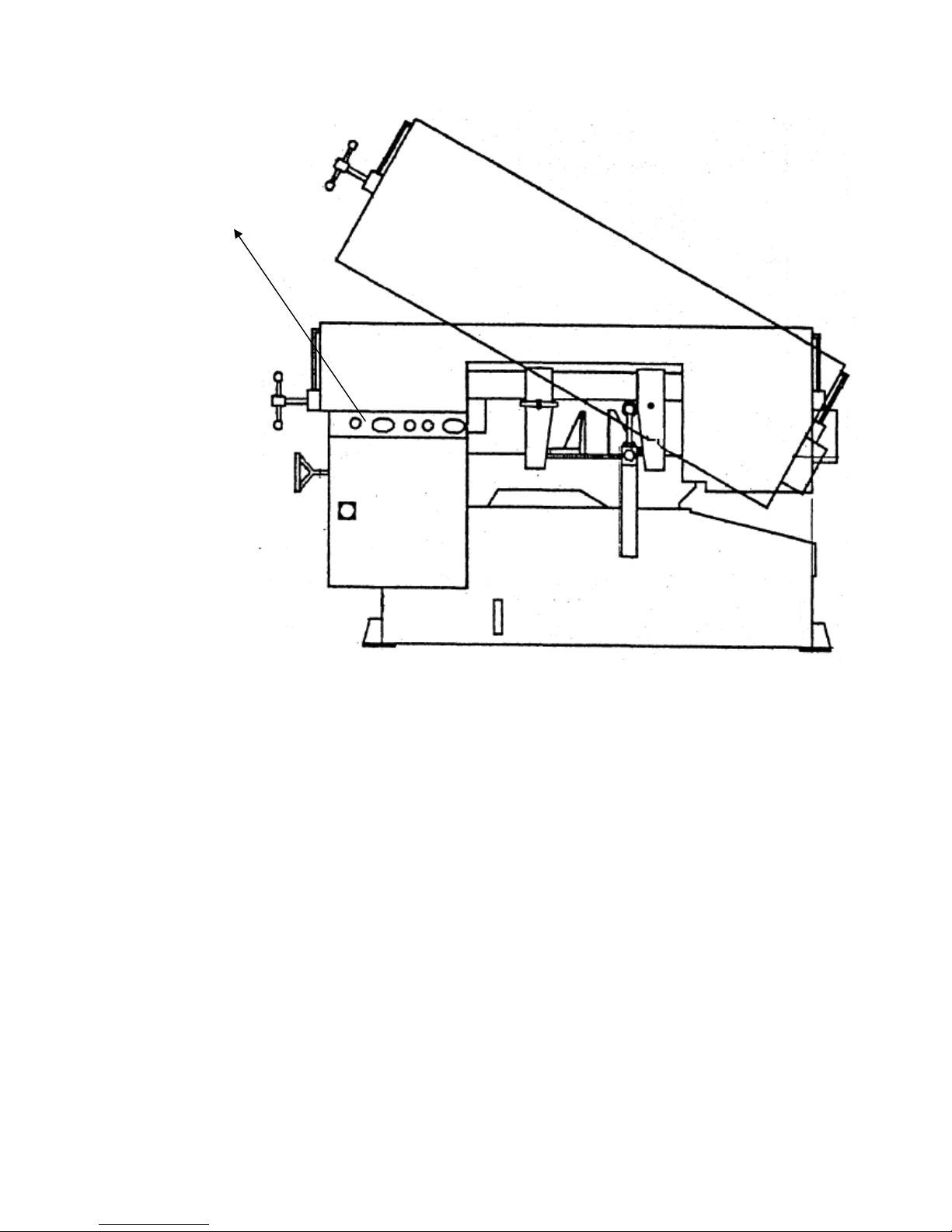
Illustration: Emergency Stop
Emergency Stop Button
Page 13

SAFETY LABELS
Please read through and understand them before operating the machine. Refer to Illustration: Safety
Labels.
Label
Meaning
Label
Meaning
Impact Hazard
WEAR SAFETY SHOES. Do
not approach dropping area
during operation.
Read Operator’s Manual
This manual has important safety
information. Read through it
carefully before operating this
machine to prevent personal injury
or machine damage.
Keep Unauthorized
Personnel Away
Do not step.
Do not stand on the machine or on
the accessories!
DANGER: Running Blade
Blade runs through this
area. Keep your hands away
from a running blade to
avoid severe injury. The
arrow indicates direction of
the blade.
Cutting Hazard
KEEP COVER CLOSED / KEEP HAND
OFF while the blade is running. Turn
power off before opening cover.
Failure to follow the warning can
result in severe injury.
Hazardous Voltage
TURN POWER OFF before
servicing. Failure to
following the warning can
result in severe injury.
Burn Hazard/Hot Surface
Hand Crush/Force from
Above
Crush hazard by vise
Loose Hand Hazard
KEEP HAND OFF. Do not
touch chip conveyor. Failure
to follow the warning can
result in severe injury.
Pinch Point/Hand Entanglement
Page 14
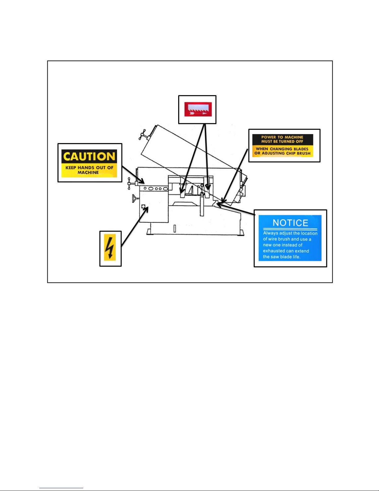
Illustration: Safety Labels
SW-100T SafetyLabels
Page 15

HEARING PROTECTION
Always use ear protection!
When your machine is running, noise generated by the machine may come from the following:
Saw blade during cutting or material feed mechanism
Wire brush unit
Chip conveyor unit
Speed reducer
Hydraulic motor/pump
Belt transmissions variable speed motors
Blade motor
Coolant pump
Drive wheel
Parts not assembled tightly causing mechanical vibration
Our products pass noise testing less than 78 dBA. Noise level vary according to working conditions and
we recommend ear plugs or other hearing protection at all time. If your machine produces an
undesirable noise while it is running, you should:
1. Make sure all maintenance tasks have been performed following the prescribed maintenance
schedule (Refer to Section 6).
2. If maintenance does not seem to solve the problem, follow the troubleshooting procedures under
Section 7.
RISK ASSESSMENT
Risk assessment generally takes account of intended use and foreseeable misuse, including process
control and maintenance requirements. We made every effort to avoid any personal injury or equipment
damage during the machine design stage. However, the operator (or other people) still needs to take
precautions when handling any part of the machine that is unfamiliar and anywhere on the machine
that has potential hazards (e.g. the electrical control box).
Page 16

Section 2
GENERAL
INFORMATION
SPECIFICATION
MACHINE PARTS IDENTIFICATION
FLOOR PLAN
This band saw machine is designed by our R&D engineers to provide you the following features and
advantages:
Safety
This machine is designed to fully protect the operator from its moving parts during cutting
operation.
The machine and each compoment has passed strict testing (Council Directive on the
approximation of the laws of the Member States relating to Machinery).
The machine will shut off automatically when the saw blade is broken, protecting both the
operator and the machine.
Convenience & High-Performance
The machine is designed in the way that the operation and adjustment can be easily
performed.
The machine will stop automatically when out of stock.
Dual valve system is designed to achieve optimal cutting performance with the simple setting
of feed rate and perspective cutting pressure for different material.
Durability
The intended life-span of the machine is counted based on regular daily operation. It is
calculated with the life expectancy of 10 years under normal operating condition and exact
attention to the maintenance schedule.
8 hours × 5 days × 52 weeks × 10 years = 20,800 hours
Page 17

SPECIFICATION
Model
SW-100T
Semi-Automatic Horizontal Bandsaw
Capacity
Angle
0°
45°
Round
250 mm (10”)
190 mm (7.5”)
Square
230 mm (9”)
190 mm (7.5”)
Rectangular (H x W)
230 x 400 mm (9” x 15.7”)
190 x 190 mm (7.5” x 7.5”)
Saw Blade
Speed
60Hz
29, 46, 65, 98 m/min (95, 150, 213, 321fpm)
50Hz
24, 38, 53, 81 m/min (78, 124, 173, 265 fpm)
Size
3,350 x 27 x 0.9 mm (132” x 1.06” x 0.035”)
Tension
Hydraulic with automatic blade breakage detection
Guide
Interchangeable tungsten carbide
Cleaning
Steel wire brush with flexible drive shaft driven by main motor
Motor
Output
Saw Blade
2 HP (1.5 kW)
Hydraulic
1/4 HP (0.2 kW)
Coolant Pump
1/8 HP (0.1 kW)
Coolant Tank Capacity
20 L (5.28 gal)
Vise Control Method
Manual
Feeding Mode
Manual
Workbed Height
640 mm (25”)
Weight
Net
540 kg (1,188 lb)
Gross
640 kg (1,408 lb)
Floor Space (W x D x H)
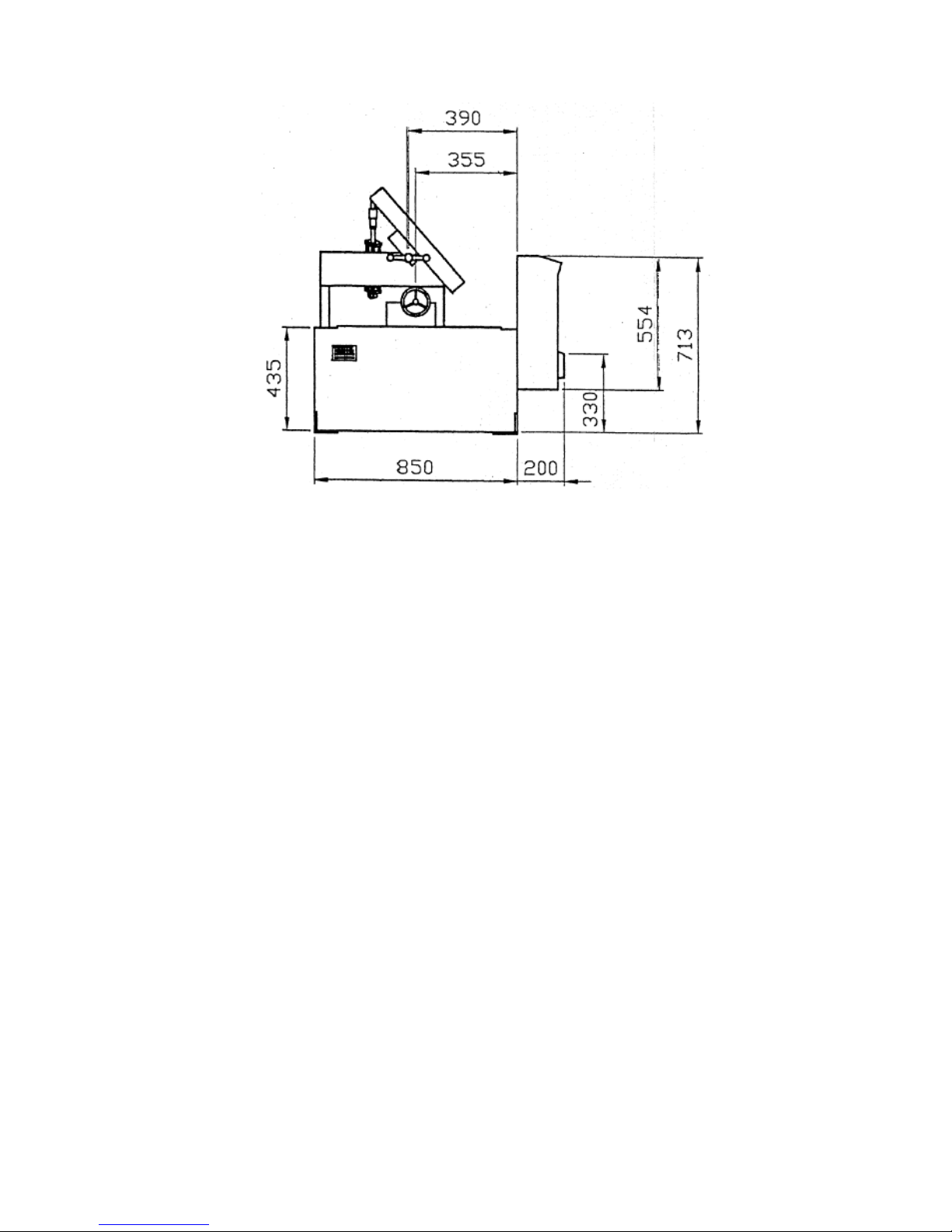
1,700 x 1,100 x 1,400 mm (67” x 43.5” x 55.5”)
Page 18
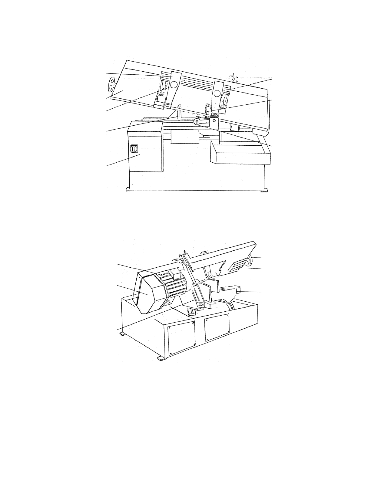
MACHINE PARTS IDENTIFICATION
Fixed vise
Guide arm handle
Dovetail slide guide
Control box
Dovetail gauge plate
Idle wheel cover
Movable vise
Stopper
Motor
Variable blade
speed control
Blae tension handwheel
Blade tension device
Bed
Hydraulic feed
cylinder
Page 19
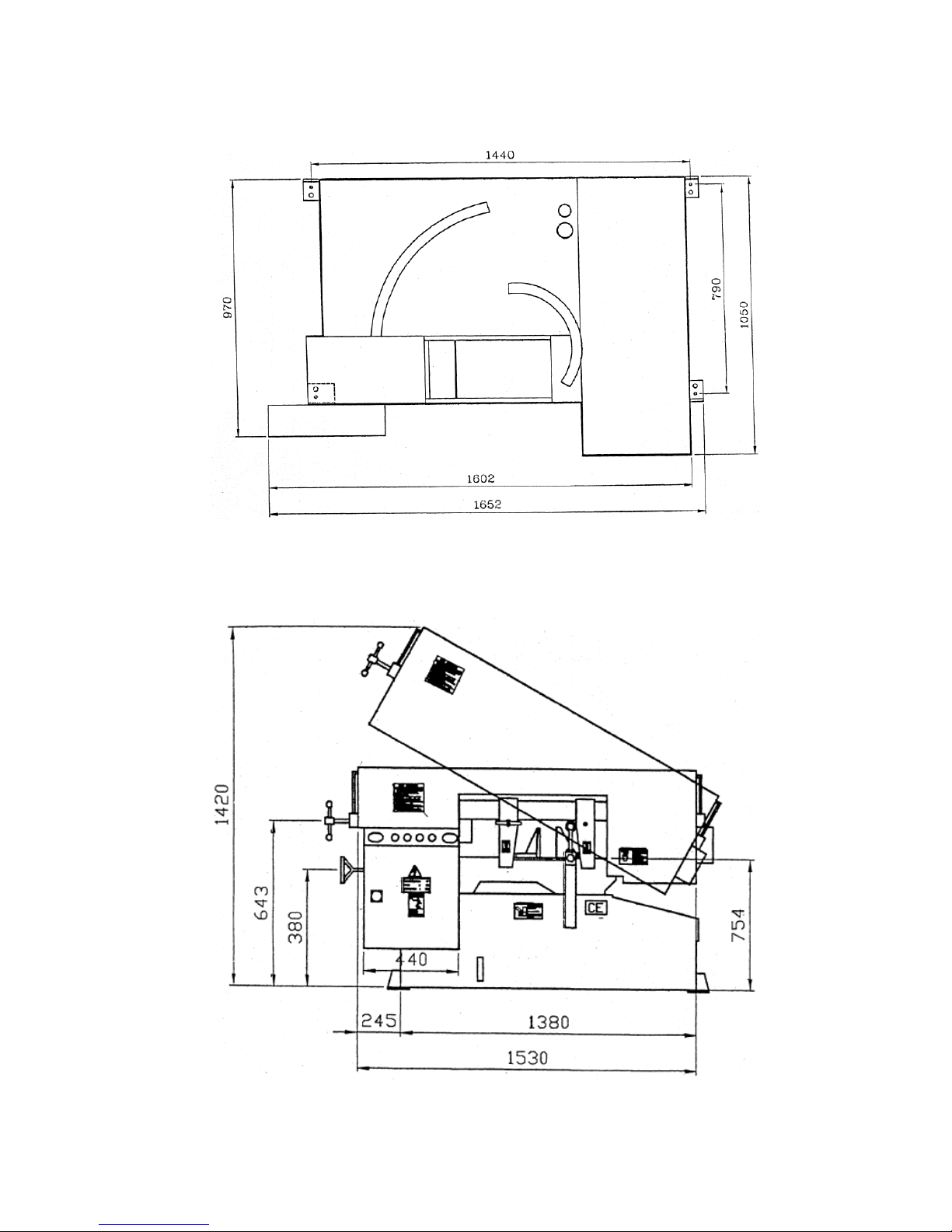
FLOOR PLAN
Machine top view
Machine front view
Page 20
Machine front view
Page 21

Section 3
MOVING &
INSTALLATION
LOCATION & ENVIRONMENT
UNPACKING & INSPECTING
LIFTING
REMOVING SHIPPING BRACKET
CLEANING
INSTALLING
RELOCATING
LOCATION & ENVIRONMENT
For your safety, please read all information regarding installation before proceeding. Install your machine
in a place satisfying all of the following conditions:
Space:
Leave enough free space around the machine for loading work and unloading cut-off pieces as
well as for maintenance and inspection. Refer to Section 2 General Informattion for machine
dimensions and floor space.
Environment:
Well lighted (500 lumen at minimum).
Floor kept dry at all times in order to prevent operators from slipping.
Away from direct exposure to the sunlight
Room temperature between 5˚C to 40˚C.
Humidity level kept at 30~95%“(without condensation) to avoid dew on electric installation
and machine.
Away from vibration of other machines
Away from powders or dusts emitted from other machines
Avoid uneven ground. Choose a solid level concrete floor which can sustain weight of both
machine and material.
Limit the operation area of the machine to staff only.
Page 22

UNPACKING & INSPECTING
Unpack your machine carefully to avoid damage to machine parts or surfaces.
Upon arrival of your new band saw, please confirm that your machine is the correct model and it
comes in the same specification you ordered by checking the model plate on the machine base.
It is also imperative that a thorough inspection be undertaken to check for any damage that could
have occurred during shipping. Pay special attention to machine surface, equipments furnished and
the electrical and hydraulic systems for damaged cords, hoses and fluid leaks.
In the event of damage caused during shipping, please contact your dealer and consult about filing a
damage claim with the carrier.
Your machine comes in with a set of tools for you to maintain the machine. The accessories
furnished are as follows:
1.
Tool box
1 pc
2.
Grease gun
1 pc
3.
Screwdriver (+, -)
2 pcs
4.
Open-ended spanner
3 pcs
5.
Hexagon wrench
1 set
6.
Chip spade (only for manual models)
1 pc
7.
Operation manual
1 pc
Should you find any missing accessories, please contact your local agent immediately.
Page 23
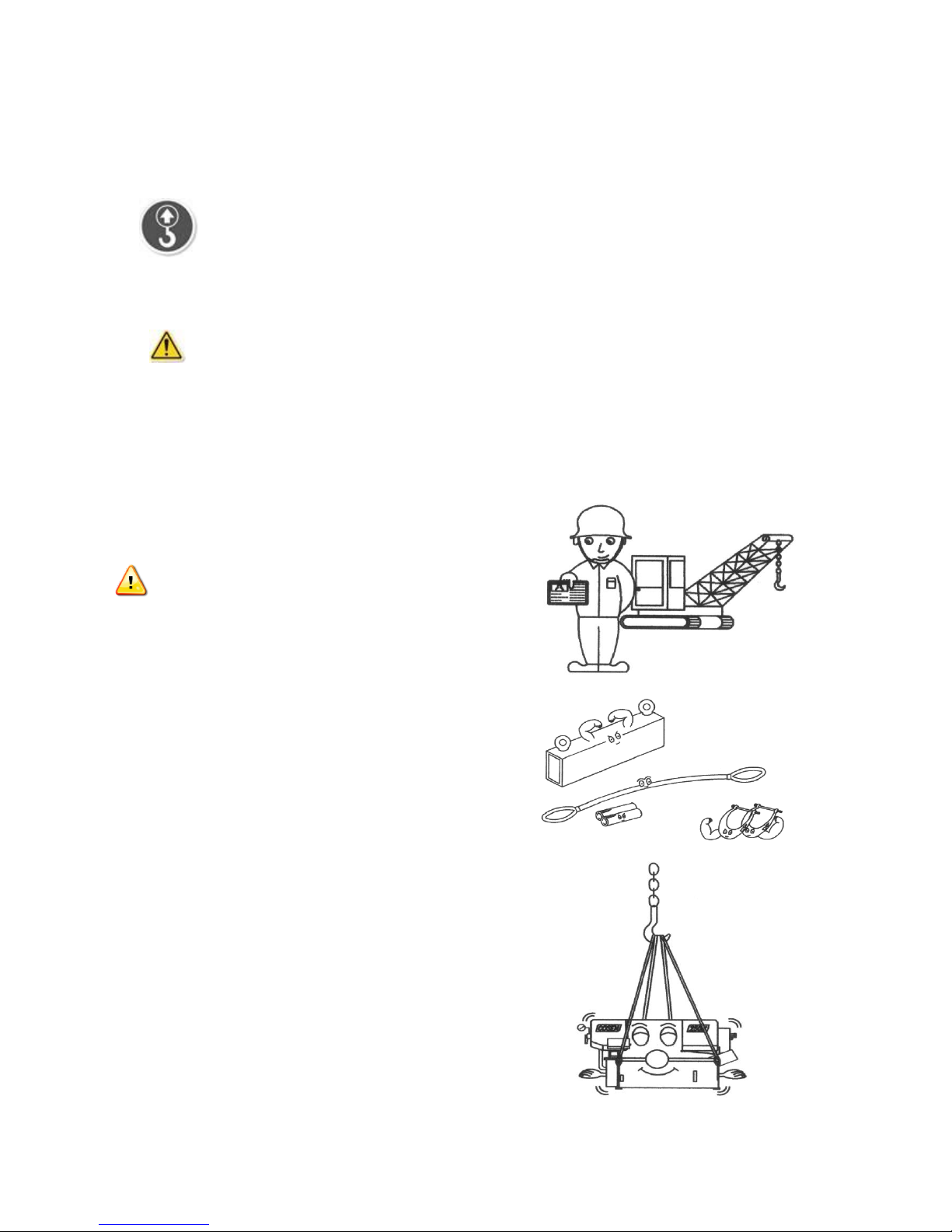
LIFTING
When moving the machine, we strongly suggest you choose any one of the methods described below to
move your machine.
1. (Only applies to the machine with the design of the hanging point.)
Move the machine to its location by using a crane and a wire rope sling that can fully withstand the
weight of the machine (refer to machine specification under Section 2 General Information).
Machine hanging with a crane should be done strictly according to the hanging points
designated by the original manufacturer. If there is any doubt on missing hanging points on your
machine, please consult with the original manufacturer or its qualified agent before hanging the
machine.
Machine lifting is likely to damage the machine
if not performed properly.
Warning: You must have a qualified crane
operator to perform the job.
You must use tools and equipment with the
proper tensile strength and use proper method
when moving your machine.
Apply the wire rope sling to the lifting hooks on
the four ends of the machine. Refer to
Illustration: Lifting Points for exact locations.
Slowly lift the machine. Be sure to protect the
machine from impact or shock during this
procedure. Also watch out your own fingers and
feet to avoid injuries.
Page 24

Keep the machine well balanced during lifting
process and make sure the wire rope does not
interfere with the saw frame.
When you work together with more than two
people, it is best to keep constant verbal
communication with each other.
2. Use a forklift (Only applies to the machine with the design of the lifting point.)
Make sure that the lifting rod can fully withstand the weight of the machine. (Refer to Section 2 –
General Information for Specifications.)
Machine lifting with a forklift should be done strictly according to the lifting points
designated by the original manufacturer. If there is any doubt on missing lifting points on your machine,
please consult with the original manufacturer or its qualified agent before lifting the machine.
Machine lifting is likely to damage the machine
if not performed properly.
You must have a qualified forklift operator
to perform the job.
You must apply proper forklift technique to
avoid damage to the machine.
Make sure the forks are able to reach in
at least 2/3 of the machine depth.
Page 25
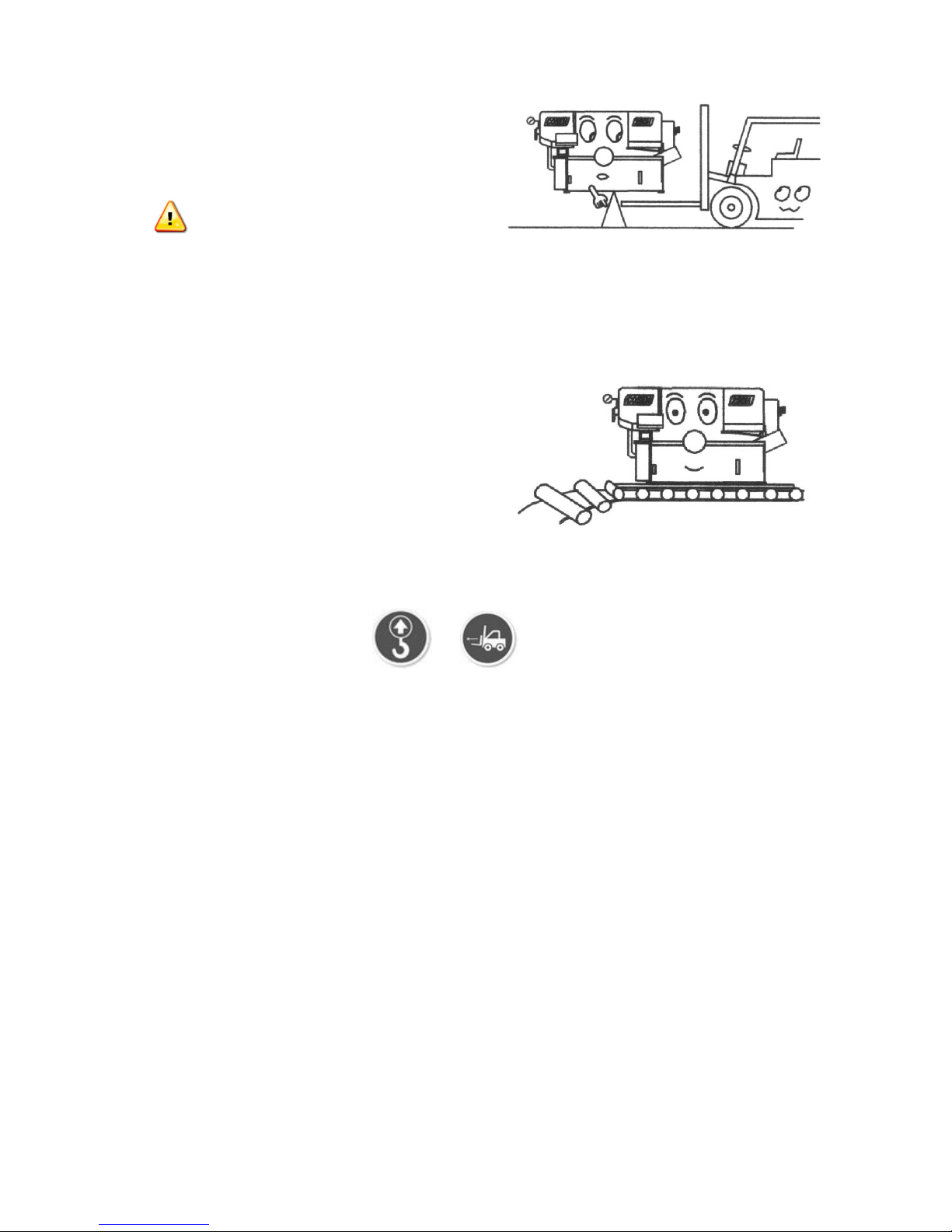
You must keep the machine balanced at all
times.
Make sure the forks are centered before
use.
(Illustration only. Please follow user guide of your forklift.)
3. Use rolling cylinders
You can use rolling cylinders to move your machine in a small machine shop environment.
You must use rolling cylinders made in material
of proper compressive strength.
4. Other ways to move
If the machine does not have or stickers, please contact your local agent
immediately.
Page 26

Illustration: Lifting Points
Minimum weight capacity for each wire rope: 1 ton
Total number of wire ropes required: 4
Page 27

REMOVING SHIPPING BRACKET
After the machine has been properly
positioned, remove the shipping bracket that is
used to lock the saw frame and the saw bed.
Retain this bracket so that it can be used again
in the event that your machine must be
relocated.
CLEANING
After the machine has been placed at the designated position, remove the rust-preventive grease with
wiping cloth dampened with cleaning oil or kerosene. Apply machine oil to machine surfaces that are
prone to rust.
Do not remove the rust-preventive grease with a metal scraper and do not wipe the
painted surfaces with solvent as doing so would damage surface paint.
INSTALLING
Our bandsaw machine is relatively easy to install. Follow these six easy steps to install your machine.
Supplying hydraulic oil
Open the filler cap and fill the hydraulic oil tank to
above 2/3 or full level.
Check the sight gauge to make sure the oil level in
the tank.
Refer to specification chart under Section 2
for tank capacity.
Oil tank should be full already if it is a new
machine that operates for the first time.
Supply
cutting fluid
Supply
hydraulic oil
Connect
electric
power
Leveling &
anchoring
Installing roller
table
(Optional)
Page 28

Supplying coolant
Fill the coolant tank to the middle level of the sight
gauge by pouring the coolant from above the chip
conveyor.
Use the sight gauge to check the coolant level
remaining in the tank.
Always check the coolant supply before
starting the machine. If the coolant pump is
started without enough coolant supply in
the tank, the pump and its drive motor may
be damaged.
Refer to specification chart under Section 2
General Information
for tank capacity.
Consult your coolant supplier for bandsaw
use regarding coolant type and mix ratio.
Page 29

Connecting electric power
Have a qualified electrician make the electrical connections.
If the power supply voltage is different from the transformer and motor connection voltage
shown on the label attached to the electrical compartment of the machine, contact us or your agent
immediately.
Connect to power supply independently and directly. Avoid using the same power supply with
electric spark machines such as electric welder. Unstable electric tension may affect your machine’s
electric installation from working properly.
Ground the machine with an independent grounding conductor.
Supply voltage: 90 - 110 of nominal supply voltage.
Source frequency: 99 - 101 of nominal frequency.
Refer to the specification chart under Section 2 for total electric power consumption of the
motors and make sure your shop circuit breaker is capable of this consumption amount. Also use a
power supply cable of proper size to suit the power supply voltage.
1. Turn off the shop circuit breaker.
2. Make sure the machine circuit breaker switch on the
electrical compartment door is turned to OFF.
3. Remove the screw securing the electrical
compartment and then open the door.
4. Pull the power supply cable and grounding conductor
through the power supply inlet into the electrical
compartment. (Shown right)
5. Connect the power supply cable to the circuit breaker
(N.F.B.) to the R, S and T terminals, and connect the
ground cable to the E terminal.
6. Close the compartment door and fasten the screw
back.
7. Turn on the shop circuit breaker and then turn the
machine circuit breaker switch to ON. The Power
Indicator on the control panel will come on.
8. Pull to unlock the Emergency Stop button and press
the hydraulic ON button to start the hydraulic motor.
Power Supply Inlet
Page 30

9. Make sure the sawing area is clear of any objects.
Start the blade and check the blade rotation. If the
electrical connections are made correctly, the blade
should run in a counterclockwise direction. If not,
shut the hydraulics off, turn off the machine as well as
the shop circuit breaker. Then swap the power the
power cable conductors connected to R and T
terminals.
10. Repeat step 6 to 9 to ensure the electrical
connections are in the right order.
Leveling
Place spirit level on the vise slide plates and the work
feed table.
Level the machine in both directions i.e. along and
across the machine. Adjust the level of the machine by
turning the leveling bolts.
Make sure all leveling bolts evenly support the
machine weight.
Anchoring the machine
Normally there is no need to anchor the machine. If the machine is likely to vibrate, fix the machine to
the floor with anchor bolts.
Shock absorption steel plates are provided and can be placed under each leveling bolt to prevent their
sinking into the concrete floor.
Page 31

Installing roller table (optional)
The roller table is used to support long material at
the rear and/or the front of the machine.
If you have ordered the optional roller table for
cutting long material, position it before or behind
the machine.
Level the roller table and the stand with the
machine by adjusting the leveling bolts.
Installing fire control device
Install a fire extinguisher or any other fire control device in the shop in case a fire breaks out.
RELOCATING
We recommend you follow these procedures when relocating or shipping your machine to other place:
1. Descend the saw frame to its lowest position then turn off the power.
2. Fix the saw frame using the shipping bracket that originally came with the machine.
3. If you are shipping the machine, pack the machine carefully with industrial plastic wraps to
protect it from dust.
4. Use a crane or forklift to raise it. If a crane is used to lift the machine, ensure that the lifting cable
is properly attached to the machine.
5. Do not forget to include the equipments originally furnished including the shock absorption steel
plates and the instruction manual.
Adjust bolts
Page 32

Section 4
OPERATING
INSTRUCTIONS
SAFETY PRECAUTIONS
BEFORE OPERATING
CONTROL PANEL
CHECK PRIOR TO OPERATION
CUTTING OPERATIONS
UNROLLING & INSTALLING THE BLADE
ADJUSTING BLADE TENSION
ADJUSTING WIRE BRUSH
ADJUSTING SAW ARM
ADJUSTING HORIZONTAL STOP SPRING CUSHION
Page 33

SAFETY PRECAUTIONS
For your safety, please read and understand the instruction manual before you operate the machine.
The operator should always follow these safety guidelines:
• The machine should only be used for its designated purpose.
•
Do not wear gloves, neckties, jewelry or loose clothing/hair while operating the machine.
•
For eye protection, always wear protective safety glasses.
•
Check the blade tension and adjust blade guides before starting the machine.
•
Use auxiliary clamping or supporting devices to fix material in place before cutting long
workpieces. Always make sure the material is clamped firmly in place before starting to cut.
•
Do not remove jammed or cut-off pieces until the blade has come to a full stop.
•
Keep fingers away from the path of the blade.
•
Protection devices should be in place at all times. For your own safety, never remove these
devices.
•
Disconnect machine from the power source before making repairs or adjustments.
•
Wear protection gloves only when changing the blade.
•
Do not operate the machine while under the influence of drugs, alcohol or medication.
•
Do not take your eyes off the machine while in operation.
•
Do place warning signs to mark out machine work zone and restrict entry to be staff-only.
Page 34

BEFORE OPERATING
Choosing an appropriate saw blade and using the right cutting method is essential to your cutting
efficiency and safety. Select a suitable saw blade and cutting method based on your work material and
job requirements e.g. cutting accuracy, cutting speed, economic concern, and safety control.
Wet cutting
If you choose dry cutting or low-speed cutting, the chips may accumulate in machine parts and may
cause operation failure or insulation malfunction. We suggest you choose wet cutting to avoid machine
damage.
Cutting unknown materials
Before cutting an unknown material, consult the material supplier, burn a small amount of chips from
the material in a safe place, or follow any other procedure to check if the material is flammable.
Never take your eyes off the machine while in operation.
Cutting fluid
For cooling and lubrication purpose, we recommend you use water-soluble cutting fluids. The following
table lists out its pros and cons for your reference.
Pro
Con
Have a high cooling effect
Not flammable
Economical
Does not require cleaning of the cut
products
Remove machine paint
Lose its rust protection effect if
deteriorated
Tend to create foam
Subject to decay
Decline in performance, depending on
the quality of the water used for
dilution
Never use water as your coolant.
Always add coolant into water for better mix result.
Consult your coolant supplier for bandsaw use regarding coolant type and mix ratio.
Before starting a cutting job, make sure there is sufficient amount of coolant in the tank. Check
the fluid level through the sight gauge. Please refer to machine specifications in this manual
(Section 2) for tank capacity.
Page 35

CONTROL PANEL
The control panel is located on the top of the electrical box. It includes the following function: power
system and cooling system. The operator must fully understand the function of each switch and button
before operating the machine.
Control Buttons
1. Blade start button
Press this button to start the blade.
2. Emergency stop button
Press this button to stop the machine in an emergency. When the button is pressed, it brings the
machine to a full stop. The button locks when pressed. In order to unlock it, please turn the button
clockwise.
3. Saw bow up button
When this button is pressed, the saw bow rises until the operator lets go of the button.
4. Saw bow down button
When this button is pressed, the saw bow descends.
5. Flow control valve
This valve is used to adjust the descend speed of the saw blade.
Turning the valve clockwise increases the blade descend speed.
Blade descend speed is a determining factor to a good cutting time and quality cutoff surface.
Page 36

CUTTING OPERATIONS
Do not connect power cord to power source until the following instructions are clearly
understood and followed.
Selecting Blade Speed
Blade speed selection should be made according to the material being cut. The following chart provides
information on blade speed and is used for reference only.
Material
Speed
Pulley Groove Used
50 Hz
60 Hz
Motor pulley
Saw Pulley
High speed alloy, stainless and
heavy cross section material
57
68
Smallest
Large
Tool, stainless and alloy steel,
bearing bronze
100
120
Small
Medium
Cast iron, mild steel, hard brass,
bronze
164
196
Medium
Small
Plastic, copper, soft brass,
aluminum, other light materials
277
330
Large
Smallest
Some materials due to manufacturing processes such as certain types of cast iron pipe or
materials containing certain types of welds cannot be cut on the machine.
Changing Blade Speed – 4 Speed Step Pulley
(Fig 1)
Step 1 - Remove pulley cover.
Step 2 - Loosen lock handle.
Step 3 - Position belt in proper grooves
according to below speed selection chart
attached on the pulley cover.
Step 4 - Make sure the belt is tightly and
securely positioned in the groove and
tighten lock handle.
Step 5 - Install pulley cover back in place.
Page 37

Speed Selection Chart
Selecting Blade
For best results, the correct number of teeth on
the workpiece is important. For mild materials,
the 3-6-12-24 rule applies. For hard materials,
the 6-12-24-48 rule applies.
At least two teeth must be in cutting area at all
times. A finer blade tooth is used when cutting
thin sections and harder materials. Coarse teeth
are for sawing large work and tough gummy
metals.
Page 38

Adjusting Feed Rate (Cutting Pressure)
To obtain desired feed rate (cutting pressure), the “hydraulic cylinder” (Fig 3, #4) and “feed tension
spring” (Fig 3, #6) are to be adjusted together.
(Fig 3)
1. Saw bow
2. By-pass valve (Do not make
adjustment here.)
3. Workbed
4. Hydraulic cylinder
5. Bracket
6. Feed tension spring
7. Lock nut
8. Adjustment screw
9. Wire rope guide wheel
10. Lock screw
11. Gearbox
12. Screw bow bracket
Feed pressure is the amount of pressure forcing the blade downward into the material.
Proper feed pressure is important. Excessive pressure can break the blade or stall the saw.
Insufficient pressure rapidly dulls the blade.
The hydraulic cylinder regulates the rate at which the blade is lowered into the material being cut.
Adjusting the blade descend speed control knob provides an infinite choice for feed rate.
When cutting workpiece of 2 mm thick or below, please adjust the blade descend speed control
knob to between “1~2” gradually; when cutting workpiece of 3 mm and above, to “3~4” gradually.
The by-pass valve (Fig 3, #2) has been factory adjusted and should not be altered.
Using blade descend speed control knob while repositioning your workpiece: When repositioning
your workpiece, raise the saw head halfway up and turn the blade descend speed control knob
clockwise all the way pass “0” to hold the saw head in position.
Adjusting Vise
Always use the vise to clamp the work. Never hand-hold the work for cutting.
Clamp material securely by turning the vise handwheel clockwise.
Vise handwheel
Page 39

Angle Cutting
The vise offers the user great flexibility in angle cutting from 0° (Position 1) to 45° (Position 2).
Page 40

Cutting at 45°
Step 1 - Move the right guide arm to the end of the dovetail guide.
Step 2 - Lift the saw bow up to the highest position.
Step 3 - Loosen the two lock bolts (Fig 5, #2 and #3) of the fixed vise jaw (Fig 5, #1). Then adjust the fixed
vise jaw until it is 45° to saw blade with an accurate protractor. (See Fig 6 below). Tighten the
two lock bolts.
Step 4 - Clamp the workpiece with the movable vise jaw. (Fig 4, #4)
Step 5 - When repositioning the vise for 90° cutting, make sure it is square with an accurate square
instrument.
Page 41

When cutting irregularly-shaped material, if possible, avoid positioning the work in the way that the cut
would be started on a sharp corner. Arrange your workpiece in the way that as many teeth as possible
will be applied to the work at one time.
Adjusting Coolant Flow
Step 1 – Press the power on button to start the saw blade drive motor.
Step 2 – Lower the saw bow.
Step 3 – Use the flow control valve (shown below) to adjust the amount of fluid flowing to the cutting
area.
Adjust the flow amount if you observe the following changes to the chips generated from cutting.
If the chips are sharp and curved, increase the coolant
flow amount.
If the chips are granulated, decrease the coolant flow
amount.
Page 42

Installing Material Stop Bracket
Step 1 - Install the depth bar (Fig 9, #2) and
tighten the set screw (Fig 9, #1). (The
depth bar is taken off from the
machine base during transit for safety
reason.
Step 2 - Lift the saw bow and clamp material
securely with vise.
Step 3 - Lower the saw bow to allow about 1
mm clearance between saw blade
teeth edge and the top of the
material. Then measure your desired
cutoff length.
Step 4 - Loosen the fastening bolt (Fig 9, #3)
Step 5 - Slide and position the stopper (Fig 9,
#6) so that the end of stopper faces
the direction of the front end of the
material. Then tighten the stopper
handle (Fig 9, #5) to fix the stopper in
the bracket (Fig 9, #4).
Step 6 - Move the stopper bracket (Fig 9, #4)
toward the workpiece so the stopper
end just touches the front of the
material, then tighten the fastening
bolt (Fig 9, #3).
Page 43

UNROLLING & INSTALLING THE BLADE
Always wear leather gloves and protection glasses when handling a blade.
Unrolling the blade
Please follow the procedures illustrated below.
Unroll and roll the blade
Installing a new blade
Make sure the power cord is disconnected from power source.
Step 1 - Elevate the saw bow until it is positioned vertically.
Step 2 - Open the idle and drive wheel covers.
Step 3 - Release blade tension by turning the blade tension handle lever counterclockwise (see below
“Adjusting Blade Tension”) and remove the blade.
Step 4 - Install the new blade with teeth pointing downward and place the blade around the wheel
consecutively following the direction of the teeth.
Step 5 - Make sure the back of the blade is also pressed against the flange of the wheels.
Page 44

Step 6 - Apply tension by turning the blade tension handle lever clockwise. Make sure you have proper
blade tension. Proper tension exists when the blade does not slip on the drive wheel when
cutting.
ADJUSTING BLADE TENSION
Turn blade tension handle lever clockwise to increase blade tension; counterclockwise to decrease
blade tension. Tension should be enough that the blade does not slip on drive wheel while cutting.
Do not apply excessive tension.
ADJUSTING WIRE BRUSH
Follow these steps to adjust wire brush to appropriate position:
Step 1 - Open the drive wheel cover.
Step 2 - Adjust the screw to make brush move up / down until it makes proper contact with the saw
blade (see below illustration).
Step 3 - Close the drive wheel cover.
Proper
Improper
ADJUSTING SAW ARM
Adjust the blade guide (guide arm) position based on the size of your workpiece:
Step 1 – Loosen the blade guide locking handle. Then adjust the guide arm to a position suitable for your
workpiece size.
Blade Tension Handle Lever
Blade Tension Device
Page 45

Step 2 – After adjustment is made, tighten the blade guide locking handle.
ADJUSTING HORIZONTAL STOP SPRING CUSHION
Always make sure the power cord is disconnected from power source when making adjustments.
Complete Cut – Adjusting Horizontal Stop Spring Cushion
The workpiece should be able to cut through completely. If it does not, please follow these steps to adjust
the horizontal stop spring cushion.
Step 1 - Place a level on the workbed (Fig 10, #4)
to make sure the bed is level.
Step 2 - Loosen the lock nut (Fig 10, #3) and
lower down the saw bow. Place the
level on top of the saw blade (Fig 10-A)
to check its leveling against the bed
horizontal line. Adjust the screw (Fig 10,
#2) until the blade is level.
Step 3 - Tighten the lock nut (Fig 10, #3) when
leveling is obtained.
If the saw blade top line is not leveled
against the bed horizontal line, the workpiece
will not be able to cut off completely.
Locking Handle
Page 46

Automatic Shut-Off – Adjusting Horizontal Stop Spring Cushion
The motor should shut off immediately after the blade has cut through the material and right before the
head comes to rest on the horizontal stop spring cushion. If it does not, the spring cushion must be
adjusted.
1. Check the horizontal stop spring cushion. Refer to “Complete Cut – Adjusting Horizontal Stop
Spring Cushion.”
2. Raise the saw head and press the power on button to ON. Lower the saw head slowly and observe
the switch mechanism.
Page 47

Section 5
ELECTRICAL
SYSTEM
ELECTRICAL CIRCUIT DIAGRAMS
Page 48

Page 49

Section 6
HYDRAULIC
SYSTEM
HYDRAULIC CIRCUIT DIAGRAM
Page 50

Page 51

Section 7
BANDSAW CUTTING:
A PRACTICAL GUIDE
INTRODUCTION
SAW BLADE SELECTION
VISE LOADING
BladeBreak -In
SOLUTIONS TO SAWING PROBLEMS
Page 52

INTRODUCTION
1. TPI: The number of teeth per inch as measured from gullet to gullet.
2. Tooth Rake Angle: The angle of the tooth face measured with respect to a line perpendicular to the cutting
direction of the saw.
3.Tooth Pitch: Tooth pitch refers to the number of teeth per inch (tpi). 1 inch equates to 25.4 mm.
A distinction is made between constant tooth pitches with a uniform tooth distance, 2 tpi for example, and
variable tooth pitches with different tooth distances within one toothing interval.
Variable tooth pitches, for instance 2-3 tpi, can be characterized by two measures: 2 tpi stands for the
maximum tooth distance and 3 tpi stands for the minimum tooth distance in the toothing interval.
Constant Variable
Min. Max
4. Set: The bending of teeth to right or left to allow clearance of the back of the blade through the cut.
5. Width: The nominal dimension of a saw blade as measured from the tip of the tooth to the back of the
band.
6. Thickness: The dimension from side to side on the blade.
7. Gullet: The curved area at the base of the tooth. The tooth tip to the bottom of the gullet is the gullet
depth.
SAW BLADE SELECTION
1. Band length
The dimensions of the band will depend on the band saw machine that has been installed.
Please refer to Section 2 – General Information
2. Band width
Band width: the wider the band saw blade, the more stability it will have.
3. Cutting edge material
The machinability of the material to be cut determines what cutting material you should choose.
7
Page 53

4. Tooth pitch
The main factor here is the contact length of the blade in the workpiece.
If it is 4P, 25.4 ÷ 4 P = 6.35 mm, that is, one tooth is 6.35 mm.
If it is 3P, 25.4 ÷ 3 P = 8.46 mm If the number is small, it means that the tooth is large.
What is written as 3/4 is that it is a variable pitch of large (3) / small (4).
The saw blade must contact the cutting material at least two pitches. In the case of a thickness of 15 mm,
4P = OK, 3P = NG.
The surface conditions will also affect the cutting rate. If there are places on the surface on the
material which are hard, a slower blade speed will be required or blade damage may result.
It will be slower to cut tubing than to cut solids, because the blade must enter the material
twice, and because coolant will not follow the blade as well.
Tough or abrasive materials are much harder to cut than their machinability rating would
indicate.
Tooth spacing is determined by the hardness of the material and its thickness in cross section.
Tooth set prevents the blade from binding in the cut. It may be either a "regular set" (also
called a "raker set" ) or a "wavy set".
The regular or raker set is most common and consists of a pattern of one tooth to the left, one
tooth to the right, and one which is straight, or unset. This type of set is generally used where
the material to be cut is uniform in size and for contour cutting.
Wavy set has groups of teeth set alternately to right and left, forming a wave-like pattern. This
reduces the stress on each individual tooth, making it suitable for cutting thin material or a
variety of materials where blade changing is impractical. Wavy set is often used where tooth
breakage is a problem. This is shown in Fig. 7.2 as follows:
Right
Straight
Left
Regular (raker) Set
Wavy Set
Fig. 7.2 The Saw Set
VISE LOADING
The position in which material is placed in the vise can have a significant impact on the cost per cut.
Often, loading smaller bundles can mean greater sawing efficiency.
When it comes to cutting odd-shaped material, such as angles, I-beams,
channel, and tubing, the main point is to arrange the materials in such a way
that the blade cuts through as uniform a width as possible throughout the
entire distance of cut.
Page 54

The following diagrams suggest some costeffective ways of loading and fixturing. Be sure, regardless of the
arrangement selected, that the work can be firmly secured to avoid damage to the machine or injury to the
operator.
BladeBreak -In
Completing a proper break-in on a new band saw blade will dramatically increase its life.
1. Select the proper band speed for the material to be cut.
2. Reduce the feed force/rate to achieve a cutting rate 20% to 50% of normal (soft materials require a larger
feed rate reduction than harder materials).
3.Begin the first cut at the reduced rate. Make sure the teeth are forming a chip. Small adjustments to the
band speed may be made in the event of excessive noise/vibration. During the first cut, increase feed
rate/force slightly once the blade fully enters the workpiece.With each following cut, gradually increase feed
rate/force until normal cutting rate is reached.
Page 55

Section 8
MAINTENANCE &
SERVICE
INTRODUCTION
BASIC MAINTENANCE
MAINTENANCE SCHEDULE
BEFORE BEGINNING A DAY’S WORK
AFTER ENDING A DAY’S WORK
Every 2 weeks
First 600hrs for new machine,then every 1200hrs
EVERY SIX MONTHS
STORAGE CONDITIONS
TERMINATING THE USE OF MACHINE
OIL RECOMMENDATION FOR MAINTENANCE
INTRODUCTION
For the best performance and longer life of the band saw machine, a maintenance schedule is necessary.
Some of the daily maintenance usually takes just a little time but will give remarkable results for the
efficient and proper operation of cutting.
BASIC MAINTENANCE
It is always easy and takes just a little effort to do the basic maintenance. But it always turns out to be a
very essential process to assure the long life and efficient operation of the machine. Most of the basic
maintenance requires the operator to perform it regularly.
Page 56

MAINTENANCE SCHEDULE
We suggest you do the maintenance on schedule.
Before beginning a day’s work
1. Please check the hydraulic oil level. If oil level volume is below 1/2, please add oil as necessary.(Filling
up to 2/3 level is better for system operation.)
2. Please check the cutting fluid level, adding fluid as necessary. If the fluid appears contaminated
or deteriorated, drain and replace it.
3. Please check the saw blade to ensure that it is properly positioned on both the drive and idle
wheels.
4. Please make sure that the saw blade is properly clamped by the left and right inserts.
5. Please check the wire brush for proper contact with the saw blade. Replace the wire brush if it is
worn out.
After ending a day’s work
Please remove saw chips and clean the machine with discharging the cutting fluid when work has been
completed.
Do not discharge cutting fluid while the saw blade is operating because it will cause severe injury on
operator’s hand.
Be sure the saw blade is fully stop, it will be performed after working inspection.
Every 2 weeks
Please apply grease to the following points:
1. Idle wheel
2. Drive wheel
3. Blade tension device
Recommended Grease:
Shell Alvania EP Grease 2
Mobil Mobilplex 48
First 600hrs for new machine,then every 1200hrs
Replace the transmission oil after operating for first 600hrs for new machine,then every 1200hrs
Recommended gear oil
Shell Omala oil HD220
Page 57

Mobil gear 630
Recommended hydraulic oil
ShellTellus 32
Mobil DTE Oil Light Hydraulic 28
Every six months
1.Clean the filter of the cutting fluid.
2.Replace the transmission oil for every half of a year(or 1200 hours).
Check the sight gauge to ascertain the transmission level.
Recommended TRANSMISSION OIL
Omala oil HD220
Mobil comp 632 600W Cylinder oil
3.Replace the hydraulic oil.
Recommended HYDRAULIC OIL
Shell Tellus 27
Mobil DTE OIL light Hydraulic28
STORAGE CONDITIONS
Generally, this machine will be stored on the following conditions in future:
(1) Turn off the power.
(2) Ambient temperature: 5℃ ~ 40℃
(3) Relative humidity: 30%~95% (without condensation)
(4) Atmosphere: use a plastic canvas to cover machine to avoid excessive dust, acid fume,
corrosive gases and salt.
(5) Avoid exposing to direct sunlight or heat rays which can change the environmental
temperature.
(6) Avoid exposing to abnormal vibration.
(7) Must be connected to earth.
TERMINATING THE USE OF THE MACHINE
Waste disposal:
When your machine can not work anymore, you should leak out the oil from machine body. Please storage
the oil in safe place with bottom. Ask a environment specialist to handle the oil. It can avoid soil pollution.
The oil list in machine:
•
Hydraulic oil
•
Cutting fluid
•
Drive wheel gear oil
Page 58

OIL RECOMMENDATION FOR MAINTENANCE
Item
Method
Revolution
Suggest oil
Dovetail guide
Keep grease covered. Antirust.
Daily
Shell R2
Roller bearing
Sweep clean and oil with lubricant.
Daily
SEA #10
Bed roller / surface
Sweep clean and oil with lubricant.
Daily
SEA #10
Nipples of bearing
Use grease gun, but not excess.
Monthly
Shell R2
Blade tension device
Use grease gun, but not excess.
Monthly
Shell Alvania EP
Grease 2,
Mobil Mobilplex
48
Reducer
Inspect once a week. Change oil of 600 hours of
using. Change it every year.
Regularly
Omala oil HD220
Mobil Gear 630
Hydraulic system
Inspect half a year. Change oil every year.
Regularly
Shell Tellus 32
Mobil DTE oil
Light Hydraulic 24
Bearing
Inserts
Oil with lubricant, but not excess.
Daily
Shell R2
Band wheel
Oil with lubricant, but not excess.
Weekly
Cylinder
Oil with lubricant, but not excess.
6 Monthly
Wire brush
Oil with lubricant, but not excess.
6 Monthly
1. Turn off the stop circuit breaker switch before servicing the machine.
2. Then post a sign to inform people that the machine is under maintenance.
3. Drain all of the cutting fluid and oil off and carefully treat them to avoid pollution.
Page 59

Section 9
TROUBLESHOOTING
INTRODUCTION
PRECAUTIONS
GENERAL TROUBLES & SOLUTIONS
MINOR TROUBLES & SOLUTIONS
MOTOR TROUBLES & SOLUTIONS
BLADE TROUBLES & SOLUTIONS
SAWING PROBLEMS & SOLUTIONS
RE-ADJUSTING THE ROLLER TABLE
INTRODUCTION
All the machines manufactured by us pass a 48 hours continuously running test before shipping out and
we are responsible for the after sales service problems during the warranty period if the machines are
used normally. However, there still exist the some unpredictable problems which may disable the
machine from operating.
Generally speaking, the system troubles in this machine model can be classified into three types, namely
GENERAL TROUBLES, MOTOR TROUBLES and BLADE TROUBLES. Although you may have other troubles
which can not be recognized in advance, such as malfunctions due to the limited life-span of mechanical,
electric or hydraulic parts of the machine.
We have accumulated enough experiences and technical data to handle all of the regular system
troubles. Meanwhile, our engineering department had been continuously improving the machines to
prevent all possible troubles.
It is hoped that you will give us your maintenance experience and ideas so that both sides can achieve
the best performance.
PRECAUTIONS
When an abnormality occurs in the machine during operation, you can do it yourself safely. If you have
to stop machine motion immediately for parts exchanging, you should do so according to the following
procedures:
•
Press HYDRAULIC MOTOR OFF button or EMERGENCY STOP button.
•
Open the electrical enclosure door.
•
Turn off breaker.
Page 60

BEFORE ANY ADJUSTMENT OR MAINTENANCE OF THE MACHINE, PLEASE MAKE SURE TO
TURN OFF THE MACHINE AND DISCONNECT THE POWER SUPPLY.
GENERAL TROUBLES AND SOLUTIONS
DISCONNECT POWER CORD TO MOTOR BEFORE ATTEMPTING ANY REPAIR OR INSPECTION.
TROUBLE
PROBABLE CAUSE
SUGGESTED REMEDY
Motor stalls
Excessive belt tension
Adjust belt tension so that belt does not slip on drive
pulley while cutting ( 1/2“ Min. deflection of belt under
moderate pressure.)
Excessive head pressure
Reduce head pressure. Refer to Operating Instructions
“Adjusting Feed”.
Excessive blade speed
Refer to Operating Instructions “Speed Selection”.
Improper blade
selection
Refer to Operating Instructions “Blade Selection”.
Cannot make
square cut
Dull blade
Replace blade.
Guide rollers not
adjusted properly
Refer to Adjustments.
Rear vise jaw not
adjusted properly
Set fixed vise jaw 90 to blade.
Excessive head pressure
Reduce head pressure. Refer to operating instructions
“Adjusting Feed.”
Increased cutting
time
Dull blade
Replace blade
Insufficient head
pressure
Increase head pressure. Refer to Operating
Instructions “Adjusting Feed.”
Reduce blade speed
Refer to Operating Instructions “Speed Selection.”
Will not cut
Motor running in wrong
direction
Reverse rotation of motor. (Motor rotation C.C.W. pulley
end.)
Blade teeth pointing in
wrong direction
Remove blade, turn blade inside out.
Re-install blade. (Teeth must point in direction of
travel. )
Hardened material
Use special alloy blades. (Consult your
industrial distributor for recommendation on type of
blade required.)
Page 61

MINOR TROUBLES & SOLUTIONS
TROUBLE
PROBABLE CAUSE
SUGGESTED REMEDY
Saw blade motor does not run
even though blade drive button
is pressed.
Overload relay activated
Reset
Saw blade is not at forward
limit position.
Press SAW FRAME
FORWARD button
MOTOR TROUBLES & SOLUTIONS
TROUBLE
PROBABLE CAUSE
SUGGESTED REMEDY
Motor will not start
Magnetic switch open, or
protector open.
Reset protector by pushing red button (inside
electric box.)
Low voltage
Check power line for proper voltage.
Open circuit in motor or loose
connections.
Inspect all lead terminations on motor for loose
or open connections.
Motor will not start,
fuse or circuit
breakers “blow”.
Short circuit in line, cord or
plug.
Inspect line, cord and plug for damaged
insulation and shorted wire.
Short circuit in motor or loose
connections
Inspect all lead terminations on motor for loose
or shorted terminals or worn insulation on
wires.
Incorrect fuses or circuit
breakers in power line.
Install correct fuses or circuit breakers.
Motor fail to develop
full power. (Power
output of motor
decreases rapidly
with decrease in
voltage at motor
terminals.)
Power line overloaded with
lights, appliances and other
motors.
Reduce the load on the power line.
Undersize wires or circuit too
long.
Increase wire sizes, or reduce length of wiring
General overloading of power
company‘s facilities.
Request a voltage check from the power
company
Motor overheat
Motor overloaded.
Reduce load on motor
Air circulation through the
motor restricted.
Clean out motor to provide normal air
circulation through motor.
Motor stalls
(Resulting in blown
fuses or tripped
circuit breakers)
Short circuit in motor or loose
connections.
Inspect terminals in motor for loose or shorted
terminals or worn insulation on lead wires.
Low voltage
Correct the low line voltage conditions.
Incorrect fuses or circuit
breakers in power line.
Install correct fuses circuit breakers.
Page 62

Motor overloaded
Reduce motor load.
Frequent opening of
fuses or circuit
breakers.
Motor overloaded
Reduce motor load
Incorrect fuses or circuit
breakers.
Install correct fuses or circuit breakers.
BLADE TROUBLES AND SOLUTIONS
DISCONNECT POWER CORD TO MOTOR BEFORE ATTEMPTING ANY REPAIR OR INSPECTION.
TROUBLE
PROBABLE CAUSE
SUGGESTED REMEDY
Teeth
strippage
Too few teeth per inch
Use finer tooth blade
Loading of gullets
Use coarse tooth blade or cutting lubricant.
Excessive feed
Decrease feed
Work not secured in vise
Clamp material securely
Blade
breakage
Teeth too coarse
Use a finer tooth blade
Misalignment of guides
Adjust saw guides
Dry cutting
Use cutting lubricant
Excessive speed
Lower speed. See Operating Instructions “Speed
selection.”
Excessive speed
Reduce feed pressure. Refer to Operating Instructions
“Adjusting Feed.”
Excessive tension
Tension blade to prevent slippage on drive wheel while
cutting.
Wheels out of line
Adjust wheels
Blade line
Run-out or
Run-in
Guides out of line
For a straight and true cut, realign guides, check
bearings for wear.
Excessive pressure
Conservative pressure assures long blade life and clean
straight cuts.
Support of blade insufficient
Move saw guides as close to work as possible.
Material not properly secured
in vise
Clamp material in vise, level and securely.
Blade tension improper
Loosen or tighten tension on blade.
Blade
twisting
Blade not in line with guide
bearings
Check bearings for wear and alignment.
Excessive blade pressure
Decrease pressure and blade tension
Page 63

Blade binding in cut
Decrease feed pressure
Premature
tooth wear
Dry cutting
Use lubricant on all materials, except cast iron
Blade too coarse
Use finer tooth blade
Not enough feed
Increase feed so that blade does not ride in cut
Excessive speed
Decrease speed
Page 64

SAWING PROBLEMS AND SOLUTIONS
Other than this manual, the manufacturer also provides some related technical documents listed as
follows:
Sawing Problems and Solutions
Vibration during cutting
Failure to cut
Short life of saw blade
Curved cutting
Broken blade
✓
✓
✓
✓
✓
Use of blade with incorrect pitch
Use blade with correct pitch suited
to workpiece width
✓
✓
✓
✓
✓
Failure to break-in saw blade
Perform break-in operation
✓
✓
✓
Excessive saw blade speed
Reduce speed
✓
✓
Insufficient saw blade speed
Increase speed
✓
✓
✓
✓
Excessive saw head descending speed
Reduce speed
✓
✓
✓
Insufficient saw head descending speed
Increase speed
✓
✓
Insufficient saw blade tension
Increase tension
✓
✓
✓
✓
Wire brush improperly positioned
Relocate
✓
✓
✓
Blade improperly clamped by insert
Check and correct
✓
✓
✓
✓
✓
Improperly clamped workpiece
Check and correct
✓
✓
✓
Excessively hard material surface
Soften material surface
✓
✓
✓
Excessive cutting rate
Reduce cutting rate
✓
✓
Non-annealed workpiece
Replace with suitable workpiece
✓
✓
✓
✓
Insufficient or lean cutting fluid
Add fluid or replace
✓
✓
✓
✓
Vibration near machine
Relocate machine
✓
✓
Non-water soluble cutting fluid used
Replace
✓
✓
✓
Air in cylinder
Bleed air
✓
✓
✓
Broken back-up roller
Replace
✓
✓
✓
✓
✓
Use of non-specified saw blade
Replace
✓
✓
✓
✓
✓
Fluctuation of line voltage
Stabilize
✓
✓
✓
Adjustable blade guide too far from
workpiece
Bring blade guide close to
workpiece
✓
✓
✓
✓
Loose blade guide
Tighten
✓
✓
Blue or purple saw chips
Reduce cutting rate
✓
✓
✓
Accumulation of chips at inserts
Clean
✓
Reverse positioning of blade on machine
Reinstall
✓
✓
✓
Workpieces are not bundled properly
Re-bundle
Page 65

✓
✓
✓
Back edge of blade touching wheel
flange
Adjust wheel to obtain clearance
✓
✓
✓
Workpiece of insufficient diameter
Use other machine, suited for
diameter of workpiece Replace
✓
✓
✓
Saw blade teeth worn
Replace
SOLUTIONS TO SAWING PROBLEMS
Table Of Contents
#1. Heavy Even Wear On Tips and Corners Of Teeth
#11. Uneven Wear Or Scoring On The Sides Of Band
#2. Wear On Both Sides Of Teeth
#12. Heavy Wear And/Or Swagging On Back Edge
#3. Wear On One Side Of Teeth
#13. Butt Weld Breakage
#4. Chipped Or Broken Teeth
#14. Heavy Wear In Only The Smallest Gullets
#5. Body Breakage Or Cracks From Back Edge
#15. Body Breaking – Fracture Traveling In An Angular
Direction
#6. Tooth Strippage
#16. Body Breakage Or Cracks From Gullets
#7. Chips Welded To Tooth Tips
#17. Band is Twisted Into A Figure "8" Configuration
#8. Gullets Loading Up With Material
#18. Used Band Is "Long" On The Tooth Edge
#9. Discolored Tips Of Teeth Due To
Excessive Frictional Heat
#19. Used Band Is "Short" On The Tooth Edge
#10. Heavy Wear On Both Sides Of Band
#20. Broken Band Shows A Twist In Band Length.
Page 66

#1. Heavy Even Wear On Tips and Corners Of Teeth
Probable Cause :
A. Improper break-in procedure.
B. Excessive band speed for the type of material being
cut. This generates a high tooth tip temperature
resulting in accelerated tooth wear.
C. Low feed rate causes teeth to rub instead of
penetrate. This is most common on work hardened
materials such as stainless and toolsteels.
D. Hard materials being cut such as "Flame Cut Edge"
or abrasive materials such as " Fiber Reinforced
Composites".
E. Insufficient sawing fluid due to inadequate supply,
improper ratio, and/or improper application
#2. Wear On Both Sides Of Teeth
Probable Cause :
A. Broken, worn or missing back-up guides allowing
teeth to contact side guides.
B. Improper side guides for band width.
C. Backing the band out of an incomplete cut.
#3. Wear On One Side Of Teeth
Probable Cause :
A. Worn wheel flange, allowing side of teeth to contact
wheel surface or improper tracking on flangeless
wheel.
B. Loose or improperly positioned side guides.
C. Blade not perpendicular to cut.
D. Blade rubbing against cut surface on return stroke
of machine head.
E. The teeth rubbing against a part of machine such as
chip brush assembly, guards, etc.
Page 67

#4. Chipped Or Broken Teeth
Probable Cause :
A. Improper break-in procedure.
B. Improper blade selection for application.
C. Handling damage due to improper opening of
folded band.
D. Improper positioning or clamping of material.
E. Excessive feeding rate or feed pressure.
F. Hitting hard spots or hard scale in material
#5. Body Breakage Or Cracks From Back Edge
Probable Cause :
A. Excessive back-up guide "preload" will cause back
edge to work harden which results in cracking.
B. Excessive feed rate.
C. Improper band tracking – back edge rubbing heavy
on wheel flange.
D. Worn or defective back-up guides.
E. Improper band tension.
F. Notches in back edge from handling damage
#6. Tooth Strippage
Probable Cause :
A. Improper or lack of break-in procedure.
B. Worn, missing or improperly positioned chip brush.
C. Excessive feeding rate or feed pressure.
D. Movement or vibration of material being cut.
E. Improper tooth pitch for cross sectional size of
material being cut.
F. Improper positioning of material being cut.
G. Insufficient sawing fluid due to inadequate
supply,improper ratio and/or improper application.
H. Hard spots in material being cut.
I. Band speed too slow for grade of material being
cut.
Page 68

#7. Chips Welded To Tooth Tips
Probable Cause :
A. Insufficient sawing fluid due to inadequate supply,
improper ratio and/or improper application.
B. Worn, missing or improperly positioned chip brush.
C. Improper band speed.
D. Improper feeding rate.
#8. Gullets Loading Up With Material
Probable Cause :
A. Too fine of a tooth pitch – insufficient gullet capacity.
B. Excessive feeding rate producing too large of a chip.
C. Worn, missing or improperly positioned chip brush.
D. Insufficient sawing fluid due to inadequate supply,
improper ratio and/or improper application.
#9. Discolored Tips Of Teeth Due To Excessive Frictional Heat
Probable Cause :
A. Insufficient sawing fluid due to inadequate supply,
improper ratio and/or improper application.
B. Excessive band speed.
C. Improper feeding rate.
D. Band installed backwards.
Page 69

10. Heavy Wear On Both Sides Of Band
Probable Cause :
A. Chipped or broken side guides.
B. Side guide adjustment may be too tight.
C. Insufficient flow of sawing fluid through the
side guides.
D. Insufficient sawing fluid due to inadequate supply,
improper ratio and/or improper application.
#11. Uneven Wear Or Scoring On The Sides Of Band
Probable Cause :
A. Loose side guides.
B. Chipped, worn or defective side guides.
C. Band is rubbing on part of the machine.
D. Guide arms spread to maximum capacity.
E. Accumulation of chips in side guides.
#12. Heavy Wear And/Or Swagging On Back
Edge
Probable Cause :
A. Excessive feed rate.
B. Excessive back-up guide "preload".
C. Improper band tracking – back edge rubbing
heavy on wheel flange.
D. Worn or defective back-up guides.
Page 70

#13. Butt Weld Breakage
Probable Cause :
A. Any of the factors that cause body breaks can also
cause butt weld breaks.
(See Observations #5, #15 and #16)
#14. Heavy Wear In Only The Smallest Gullets
Probable Cause :
A. Excessive feeding rate.
B. Too slow of band speed.
C. Using too fine of a tooth pitch for the size of material
being cut.
#15. Body Breaking – Fracture Traveling In An Angular Direction
Probable Cause :
A. An excessive twist type of stress existed.
B. Guide arms spread to capacity causing
excessive twist from band wheel to guides.
C. Guide arms spread too wide while cutting small
cross sections.
D. Excessive back-up guide "preload".
#16. Body Breakage Or Cracks From Gullets
Probable Cause :
A. Excessive back-up guide "preload".
B. Improper band tension.
C. Guide arms spread to maximum capacity.
D. Improper beam bar alignment.
E. Side guide adjustment is too tight.
F. Excessively worn teeth.
Page 71

#17. Band is Twisted Into A Figure "8"
Configuration
Probable Cause :
A. Excessive band tension.
B. Any of the band conditions which cause the band
to be long (#18) or short (#19) on tooth edge.
C. Cutting a tight radius.
#18. Used Band Is "Long" On The Tooth Edge
Probable Cause :
A. Side guides are too tight – rubbing near gullets.
B. Excessive "preload" – band riding heavily against
back-up guides.
C. Worn band wheels causing uneven tension.
D. Excessive feeding rate.
E. Guide arms are spread to maximum capacity.
F. Improper band tracking – back edge rubbing heavy
on wheel flange.
#19. Used Band Is "Short" On The Tooth Edge
Probable Cause :
A. Side guides are too tight – rubbing near back edge.
B. Worn band wheels causing uneven tension.
C. Guide arms are spread too far apart.
D. Excessive feeding rate.
Page 72

#20. Broken Band Shows A Twist In Band Length
Probable Cause :
A. Excessive band tension
B. Any of the band conditions which cause the band to
be long (#18) or short (#19) on tooth edge.
C. Cutting a tight radius.
RE-ADJUSTING THE ROLLER TABLE
If the feeding table suffers the huge stroke and the alignment is effected, follow the below procedure to
adjust.
TOOL, measuring
Measurement, Horizontal balance
Procedure
1. Screw or loosen the adjusting bolt to attain the horizontal balance (leveling) between the roller
table and the machine frame.
2. Ensure that the machine frame is not struck by the loaded material on the feeding table.
3. Check the leveling by the measuring tool.
4. After finished the adjusting, fix the roller table.
If the feeding table and the machine frame are not positioned under the horizontal balance, the
loaded material may be going up gradually and affect the cutting effect.
Page 73

Section 10
PARTS
SPARE PARTS RECOMMENDATIONS
PART LIST
SPARE PARTS RECOMMENDATIONS
The following table lists the common spare parts we suggest you purchase in advance:
Part Name
Part Name
Saw blade
Coolant tank filter
Wire brush
Steel plates
Carbide inserts
Rollers
Bearings
Belt
Hydraulic tank leak-proof
gasket
Duster seal
Rubber washer
Oil seal
O-ring
Snap ring
Drive wheel
Idle wheel
Page 74

Page 75

Page 76

Page 77

Page 78

Page 79

Page 80

Page 81

Page 82

Page 83

 Loading...