

Page 1

SV-4328ST
VERTICAL MACHINING CENTER
MAINTENANCE MANUAL
Ver 2.1
Page 2

2
PRECISION MACHINE TOOLS Ver2.1 Maintenance Manual
Chapter 1 Routine Maintenance
1-1 Routine Maintenance Checklist 4
1-2 Routine Maintenance Instruction Diagram 5
1-3 Cautions for Machine Maintenance 9
Chapter 2 The Spindle Unit
2-1 Cautions for High Speed Processing 12
2-2 Tool Shank and Broach Bolts 13
2 - 3 S p i n d l e W a r m - u p 1 5
2- 4 Spi n dl e P re - O pe r at i on C h e ck 1 6
2- 5 Spi n dl e A l ar m H an d l in g 17
Chapter 3 The Air Compressor Unit
3-1 Air Comp ressor System Layout 19
3-2 Air Compressor System Circui t 20
3-3 The Air Compressor Unit 20
3-4 Ai r C om pr esso r D eta ile d Spe ci fi c ati o ns an d F un cti o ns 21
3-5 Air Compressor Unit Usage Instr uction 24
3-6 A i r C o m p r e s s o r T r o u b l e s h o o t i n g 2 5
Chapter 4 The Lubrication Unit
4-1 C ent ralize d L ub ric ati on Sys te m Di agram 2 7
4- 2 Spi n dl e B ea ri ng Lu br i ca ti o n 2 9
4 - 3 G u i d e wa y s a n d B a l l S c r e w L u b r i c a t i o n 2 9
4-4 Lubricati on of the Cam Box of Tool Magazine 34
4-5 Counterweight Chain a nd Spro cket Be aring Lubrication 34
4 - 6 C y l i n d e r L u b r i c a t i o n 3 5
4 - 7 L u b r i ca t i o n L o c a t i o n 3 5
Chapter 5 The Spindle Oil Cooling Unit
5-1 Oil Cooling Pipeline Diagram 37
5-2 The Spindle Oil Cooling Unit 38
Chapter 6 The Electrical Unit
6- 1 Th e El e c tr i c al Uni t 4 5
Chapter 7 Appendix
7- 1 Oi l S el e c t i on 4 9
7-2 Calibratio n of Spindl e Tool Change Locati on 50
7-3 Determination of the Z-axis Mechanical Reference Point 52
7 - 4 P r o g r a m a n d S e r v o A l a r ms D e s c r i p t i o n 5 5
7-5 List of the Machine Components 110
Page 3

3
PRECISION MACHINE TOOLS Ver2.1 Maintenance Manual
Chapter 1
Routine Maintenance
Page 4

4
PRECISION MACHINE TOOLS Ver2.1 Maintenance Manual
1-1 Routine Maintenance Checklist
Routine maintenance inspection can be classified into daily, weekly, monthly and annually. The
maintenance is given when the machine functions normally The actual frequency and the operation
frequency are different. When operating the both, pay attention to abnormal noises, oil volume, air
pressure and machine abnormalities during the processing.
○:Check ◎:Add oil ☉:Clean
A:Adjustment F: Function check G: Grease coasting R: Replace when necessary
No.
1
2
3
4
5
6
7
8
Spindle unit
Lubrication
unit
Spindle oil
coolant unit
Maintenance Daily Weekly Monthly Annually Note
Spindle operation
○
warm-up
Spindle nose
Lubrication pump
☉
☉
Depending
on the brand
of the lube oil
Lubrication pump
◎
oil volume
Spindle oil
○
☉
coolant unit
Temperature
○ -1°C
difference setup
Oil coolant unit filter
☉
Air compressor
○ 5.5~7 kgf/cm²
source pressure
Air compressor
9
Air
Compressor
Unit
10
cylinder and filter
drainage
Air compressor
○
◎
unit lube oil
Air leakage of the air
11
○
compressor system
12 Coolant capacity ○
Coolant
13
Coolant box filter
☉
Page 5

5
PRECISION MACHINE TOOLS Ver2.1 Maintenance Manual
No.
Maintenance Daily Weekly Monthly Annually
Note
Depending
Internal flow of
Tool magazine
14
automatic tool
the tool change
R/
1-year
on the brand
of the lube
machine
change (ATC)
system
15
Tool sleeve and
☉
oil
tool change claw
16 CNC operation
panel
Emergency stop
button
○,F
17 Operation button ○,F
18 Spindle cooling fan
○/☉
Electric box
19
CNC axial battery ○ R
20 Machine static precision check ○,A
21 Machine position precision check ○,A Replace
22 Spindle cooling fan
23 Oil skimmer ○,F
○/☉
☉
Note: The schedule presented in table is for normal operation only. If the environment is not optimal
or if the usage frequency has exceeded the suggested basic standard, you may need to increase the
frequency of maintenance
Note 2: If there is any inconsistency between this table and instruction from elsewhere, use the
information provided on this table.
Page 6
6
PRECISION MACHINE TOOLS Ver2.1 Maintenance Manual
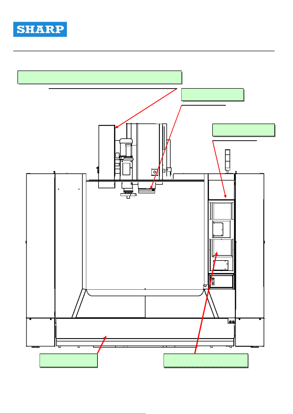
1-2 Routine Maintenance Instruction Diagram
( 14、15 ) Tool magazine / Automatic tool change system
( 1、2 ) Spindle unit
( 17 ) Operation box
( 12、13 ) Coolant
( 16 ) Emergency stop button
Page 7
7
PRECISION MACHINE TOOLS Ver2.1 Maintenance Manual
Machine precision check (20 – 21)
Page 8
8
PRECISION MACHINE TOOLS Ver2.1 Maintenance Manual
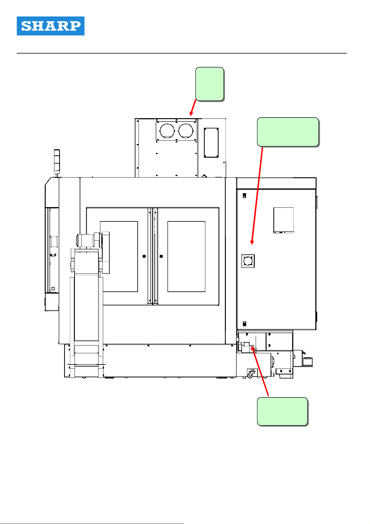
( 22 )
Fans
( 18、19 )
Electrical box
( 23 )
Oil skimmer
Page 9
9
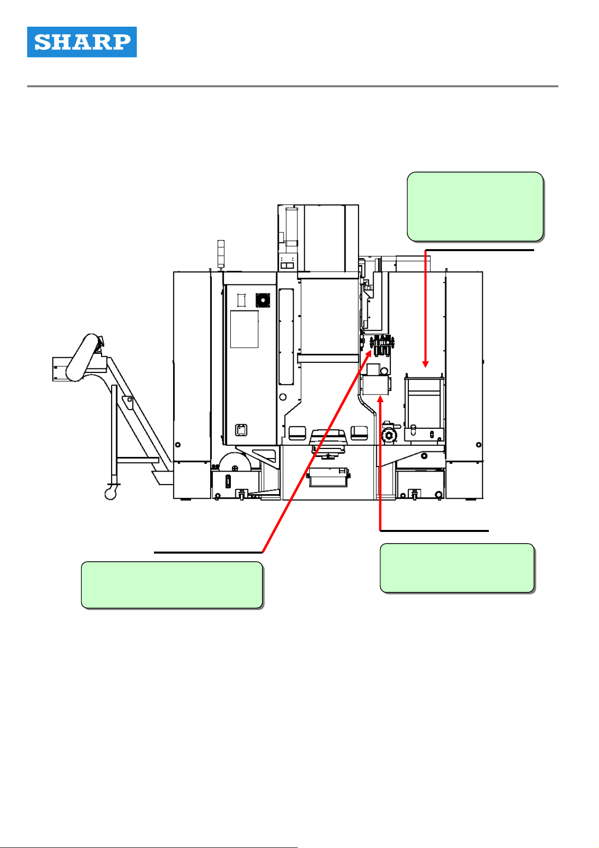
PRECISION MACHINE TOOLS Ver2.1 Maintenance Manual
( 5、6、7 )
Spindle oil temperature
controller
( 8、9、10、11 )
Air compressor preparation unit
( 3、4 )
Central lubrication system
Page 10

10
PRECISION MACHINE TOOLS Ver2.1 Maintenance Manual
1-3 Cautions for Machine Maintenance
It is important to perform maintenance on each listed items in order to maintain machine precision
and extend machine lifespan.
Erroneous operation may damage the machine or lead to injury of the operator. Be cautious about
the following matters:
Cautions Prevention
To extend the lifespan, follow the instructions given in Section
2-3 for machine warm-up before turning on the machine.
Spindle operation warm-up
Dynamic balance of the cutter
Standard broach bolts
Spindle pre-operation check
Manually loosening the
spindle’s cutter
If the machine has been stopped for a long period, follow the
instructions given in Section 2-3 for machine warm-up before
turning on the machine in order to extend the life span.
To extend the lifespan as well as to increase the precision,
please follow instructions given in Section 2-1 for usage as
well as achieving a dynamic balance for the cutter.
Broach bolt is an important component jointing the spindle and
the tool shank. Using a wrong broach bolt is hazardous for the
operation. Make sure that only the standard one is used.
Check the machine before spindle operation according to
instructions given in Section 2-4 in order to extend the lifespan
of the spindle.
When loosening the cutter of the spindle, make sure that each
step is executed correctly or may lead to personnel injury.
When changing the cutter, be cautious not to drop the cutter,
Manual installing the cutter onto
which may damage the workbench or tools. Manually change
the cutter only if necessary, and the procedures are written on
the spindle
the operation panel at the front. Press and let go of the spindle
cutter loosening button to loosen up or to grasp the cutter.
The tool magazine is controlled by CNC and motor. After
Do not touch the spinning tool
turning on the machine, do not touch the tool magazine or may
magazine
be injured. Turn off the power for changing the cutter.
Page 11

11
PRECISION MACHINE TOOLS Ver2.1 Maintenance Manual
Cautions Prevention
Spindle nose cleaning Keep the taper of spindle nose and cutter shank clean at all
time to prevent dust or iron filings affecting the precision. The
spindle has an automatic dust removal function, but the
operator should wipe the parts with standard air-laid paper for
maintaining spindle precision.
The function pressure of this air compressor is 5kgf/cm²( 71
psi ). Therefore the air pressure source has to be at least 5.5
kgf/cm²( 78 psi ) and stabilized.
This machine has an air filter that eliminates impurities and
Air quality inside the air
compressor
Lube oil from the lubricating
pump (automatic)
Adding oil to the spindle oil
cooler and setting up the
water vapor from the air. Air for the air pressure source has to
be clean and dry. Check the filter constantly to extend the
lifespan of the filter.
To effectively eliminates water vapor by the filter, drain the
water from the air tank of the air compressor. (Water drainage
is more effective in the morning).
Lube oil is released by the lubricating pump to lubricate the
guide ways and the lead screws. Insufficient lubrication may
speed up the abrasion and affect machine precision.
Always make sure that there is enough oil in the tank. If the
amount of oil is below the lower limit of the oil-level gauge, the
operation panel as well as the screen will issue a warning
message. Please add more oil as early as possible.
Oil cooling circulation system was adopted for the spindle to
effectively suppress spindle temperature increase and thus
extend the lifespan of the spindle. Use the correct type of
circulation and add more oil when the level is too low.
temperature difference
The machine adopts synchronous machine temperature
adjustment Temperature difference is set to 0 to prevent big
temperature difference, which can damage spindle bearing.
Do not change the value arbitrarily.
Page 12

12
PRECISION MACHINE TOOLS Ver2.1 Maintenance Manual
Cautions Prevention
Constantly check the guide ways of the three
axes (X, Y & Z). Check whether there are iron
Guide way check
Correctly locking the work pieces
Correctly locking the doors
filings or other types of grains attached to the
guide ways. To extend the lifespan, remove the
dust or they may scratch the slide.
When placing work pieces onto the workbench,
make sure that they are well locked or they may
spin out and cause personnel injury.
Make sure the operation door and the two side
doors are well locked to prevent the cutter from
bursting apart or iron filings from flying out,
which is dangerous.
Page 13

13
PRECISION MACHINE TOOLS Ver2.1 Maintenance Manual
Chapter 2
The Spindle Unit
Page 14

14
PRECISION MACHINE TOOLS Ver2.1 Maintenance Manual
2-1 Cautions for High Speed Processing
During high-speed processing (S = 8000 rpm or above; F = 300 mm/min or above), the shank and
the style of the cutter has a critical impact on spindle lifespan and processing precision. Matters that
need more attention are:
1). Grasp the cutter before running the spindle to avoid damaging the spindle.
2). During high-speeding chipping (8000rpm or above), use only G2.5 level cutters and shanks that
have been calibrated for dynamic balance. The reason is that vibration generated from centrifugal
force may damage the spindle bearing and rapidly wear out the cutter.
3) Balance tolerance for the shank and the cutter combination is affected by the following three
factors: rotation speed of the cutter, balance tolerance of the spindle, and weight of the shank.
Therefore, using a shorter cutter with a smaller diameter for high-speed chipping is advantageous in
terms of spindle vibration, temperature increase, thermal deformation, and processing precision.
4) The geometric shape of the cutter blade has an effect on cutter abrasion. Increase the angular
backlash of the blade can reduce abrasion due to scratches. Suitable cutter materials can also
minimize abrasion during high-speed processing; for example, cermet, tin or tic coated carbide
cutters have longer lifespan than conventional cutters. Ceramic (Si3N4) cutters are better than cermet
cutters.
5) Perform another dynamic balance calibration after combining the cutter and the shank together.
The dynamic balance standard should be G2.5 or above.
50 – 6000 rpm Level G6.3 Balance level
6000 – 18000 rpm Level G2.5
Spindle Rotation Speed (rpm) Cutter Diameter (mm) Cutter Length (mm)
6000 – 8000 125 250
8000 – 10000 100 250
10000 – 12000 80 250
12000 – 15000 65 200
15000 – 18000 50 200
Page 15
15
PRECISION MACHINE TOOLS Ver2.1 Maintenance Manual
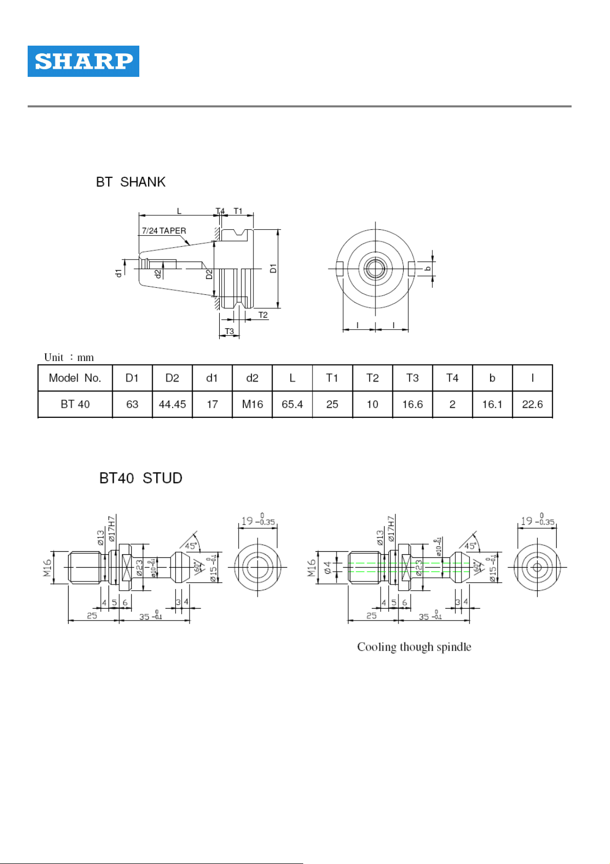
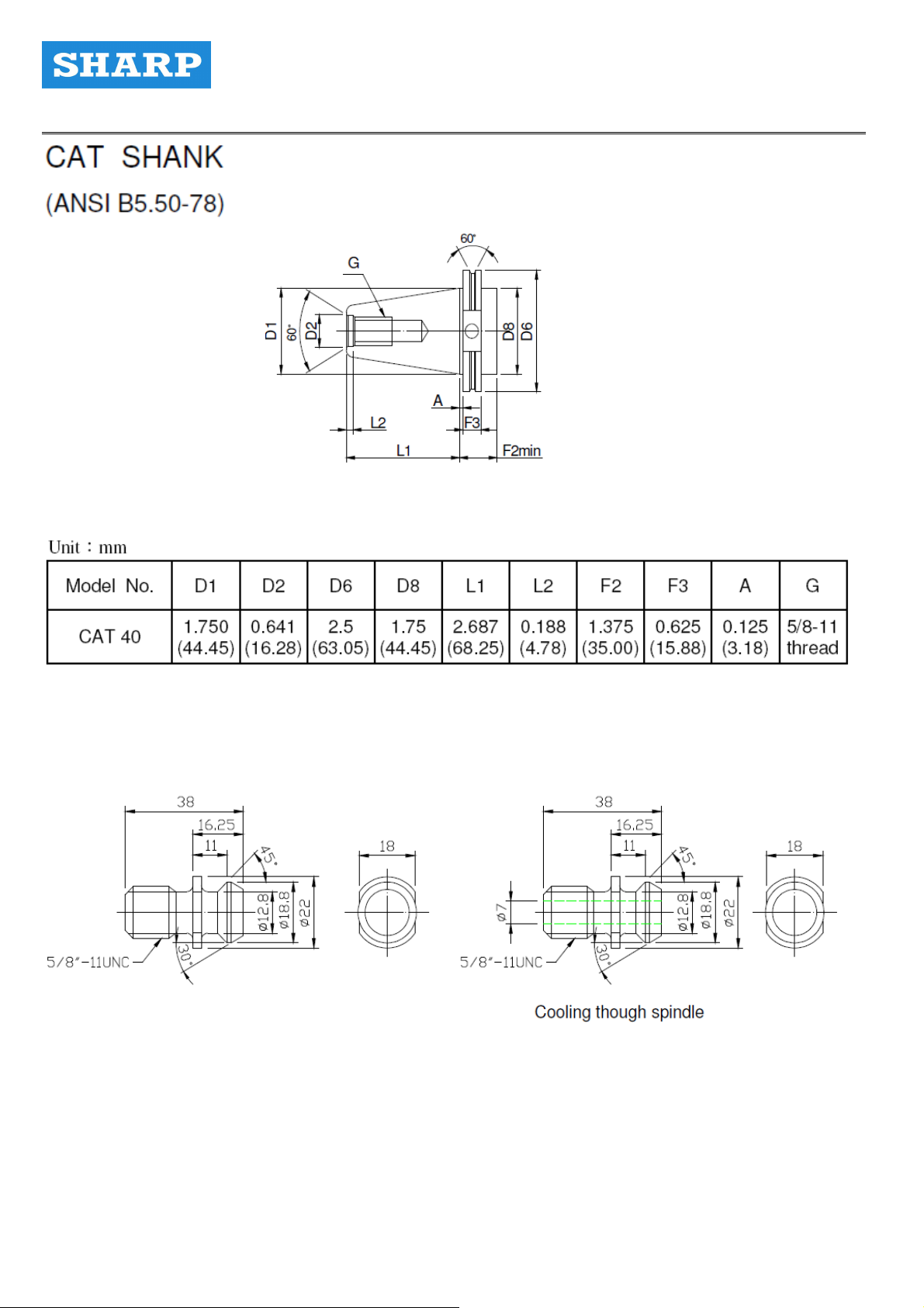
2-2 Tool Shank and Broach Bolts
Page 16
16
PRECISION MACHINE TOOLS Ver2.1 Maintenance Manual
CAT 40 STUD
Page 17

17
PRECISION MACHINE TOOLS Ver2.1 Maintenance Manual
2-3 Spindle Warm-up
This is an aerosol lubrication design, and so before turning on the machine, follow the warm-up steps
below to extend the lifespan of the spindle and to avoid damaging the bearing by letting the oil
aerosol getting into the bearing ahead.
Spindle warm-up time
Item
1 Routine operation Max Rpm 20% 10
If the spindle has been
stopped for more than two
2
hours, warm-up is
compulsive.
Spindle stopped for more
3
than 72 hours
Condition
Spindle RPM
(Maximum RPM %)
20% 10
1. 20%
2. 50%
Rotation Time
( min )
Check Contents
1. Less than 10°C
increase of
temperature
2. Shocks
3. Noises
1. Less than 10°C
increase of
temperature
Shocks
2. Noises
1. Less than 10°C
increase of
10
temperature
10
2. Shocks
3. Noises
1. 500 RPM
2. 20%
3. 40%
Spindle stopped for more
4
than 2 weeks
4. 60%
5. 80%
6. Maximum RPM
60
10
10
*10
*10
*10
Less than 10°C
increase of
temperatureShocks
Noises
4. Do not go onto the
next step until the
temperature has
become stable.
Page 18

18
PRECISION MACHINE TOOLS Ver2.1 Maintenance Manual
Cautions
1) If the shank is not installed onto the spindle, do not operate the spindle. See the figure below.
If the temperature of the bearing has increased for more than 10%, reduce the rotation speed of the
spindle to 500 and do not carry out the warm-up until the temperature is about 5°C higher than the
room temperature.
Page 19

19
PRECISION MACHINE TOOLS Ver2.1 Maintenance Manual
2-4 Spindle Pre-Operation Check
1) Check whether the air pressure source is normal.
2) Check No.7 electric oil pump tank (Refer to the diagram in Section 3-1) for whether there is
enough oil.
3) Run the spindle at 100 rpm to check whether the oil pump is functioning normally.
4) If everything is okay, carry out the warm-up according to the spindle warm-up procedures
presented in Section 2-3.
Caution
1. The oil volume and air supply volume of this aerosol lubrication unit has already been set at the
factory. Do not adjust the values arbitrarily.
2. During the maintenance, do not disassemble, bend, or flatten the output oil pipe, which may
damage the oil pipe.
3. Timely fill up the oil tank.
4. If the spindle has been stopped for more than 2 hours, run the spindle system, including the
aerosol lubrication system, at a speed that is 20% of the maximum speed.
The machine has to have a forced warm-up for 10 minutes before starting the actual work.
5. Do not adjust the oil/air mixing valve. Use the factory-set default value for lubrication interval.
Do not change the values arbitrarily or the bearing may be damaged.
6. For this unit, if the screen displays “ALARM 1002, 1056, 2004,” check and turn off the alarm
before continuing the operation.
7. Do not turn on and off the spindle repeatedly in a short period of time during the processing.
The inside of the spindle may be over-lubricated, which can cause the spindle overheated.
8. If the spindle alarm went off when starting the operation, it is due to overheated bearing. Stop
the operation. Wait until the temperature returns to normal. Check if there is any problem before
starting the warm-up and the operation.
9. It is normal to have oil dropped onto the workbench or the processing item when running the
machine. This comes from the exhausted oil aerosol. Do not block the outlet or the back pressure
may lead to temperature increase, thereby damaging the spindle bearing.
Page 20

20
PRECISION MACHINE TOOLS Ver2.1 Maintenance Manual
2-5 Spindle Alarm Handling
1) For this unit, if the screen displays “ALARM 1002, 1056, 2004,” check whether the temperature of
the protective device of the bearing is 50°C. After checking the temperature, check whether the
pipelines are abnormal, squeezed or broken. Check whether the oil cooler and the air compressor
are normal. Wait for the temperature to drop before turning on the spindle for warm-up. This is the
first line of protection for the spindle.
2) The second spindle protection is the oil pump. The oil pump has liquid level detection, and when
the level is too low, ALARM will be issued. If the oil pipeline is blocked, the screen will display
ALARM 1002.
3) The third spindle protection is the pressure switch for air pressure supply. If there is insufficient air
pressure, the mixing valve will be incapable of emitting the oil aerosol. If this ALARM goes off, check
whether the oil pipeline is broken and whether air pressure supply is sufficient.
4) If the clients still cannot turn off the alarm after checking relevant pipelines, contact the service
department of the Company. Do not modify the setting arbitrarily.
5) Messages of the ALARM signals:
1. 1002 LUBE PRESSURE FAULT:Insufficient pressure from the automatic lubrication pump
2. 1056 SPINDLE COOLER ALARM:Abnormal spindle oil cooling function
3. 2004 LUBE LEVEL ALARM:Under the standard liquid level of the oil tank of the automatic
lubrication pump
6) For relevant settings, please refer to the electrical instructions.
Page 21

21
PRECISION MACHINE TOOLS Ver2.1 Maintenance Manual
Chapter 3
The Air Compressor Unit
Page 22
22
PRECISION MACHINE TOOLS Ver2.1 Maintenance Manual
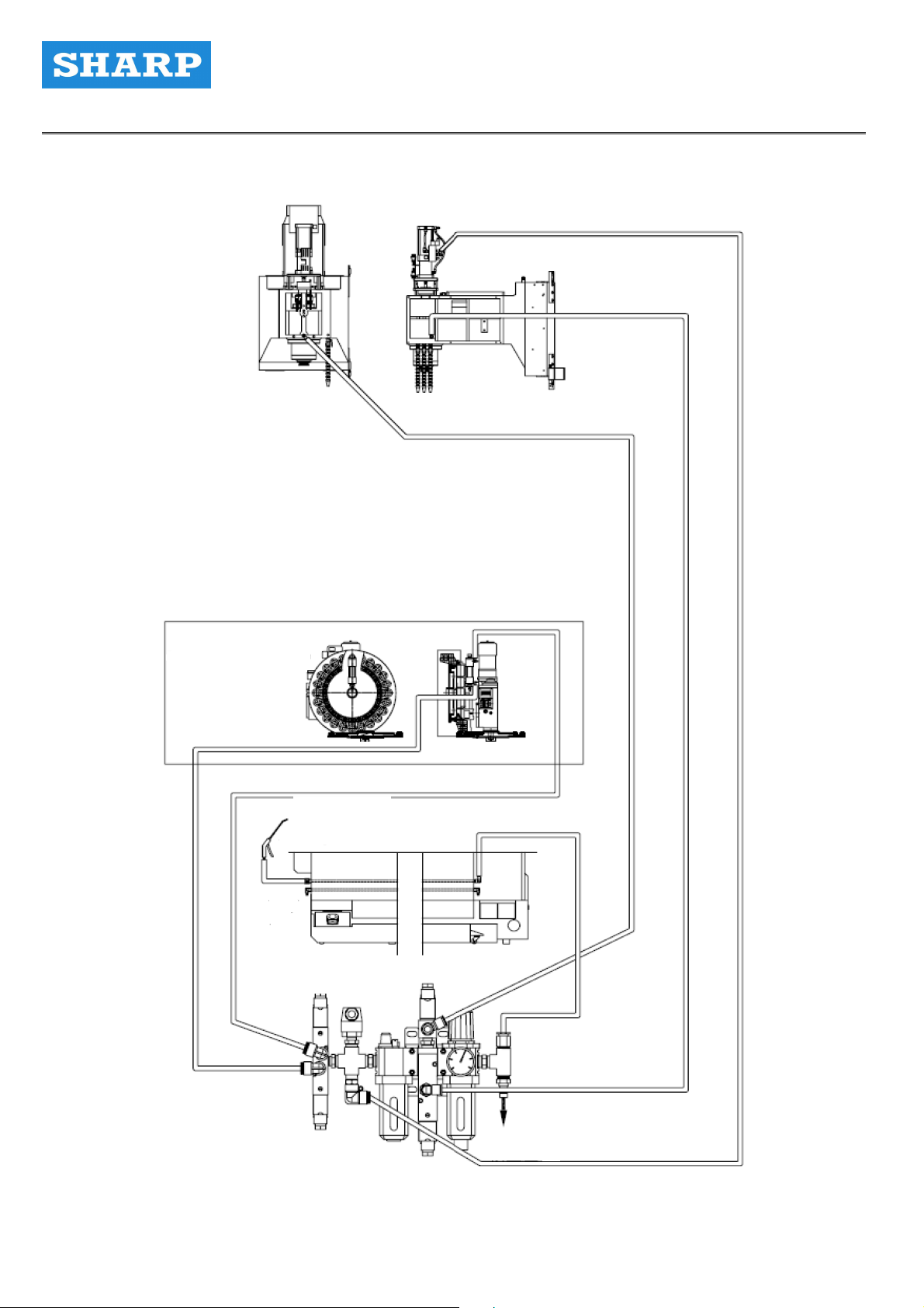
3-1 Air Compressor System Layout
ATC
Rotary disk type tool magazine
Air gun
Machine front
Air pressure source
Page 23
23
PRECISION MACHINE TOOLS Ver2.1 Maintenance Manual
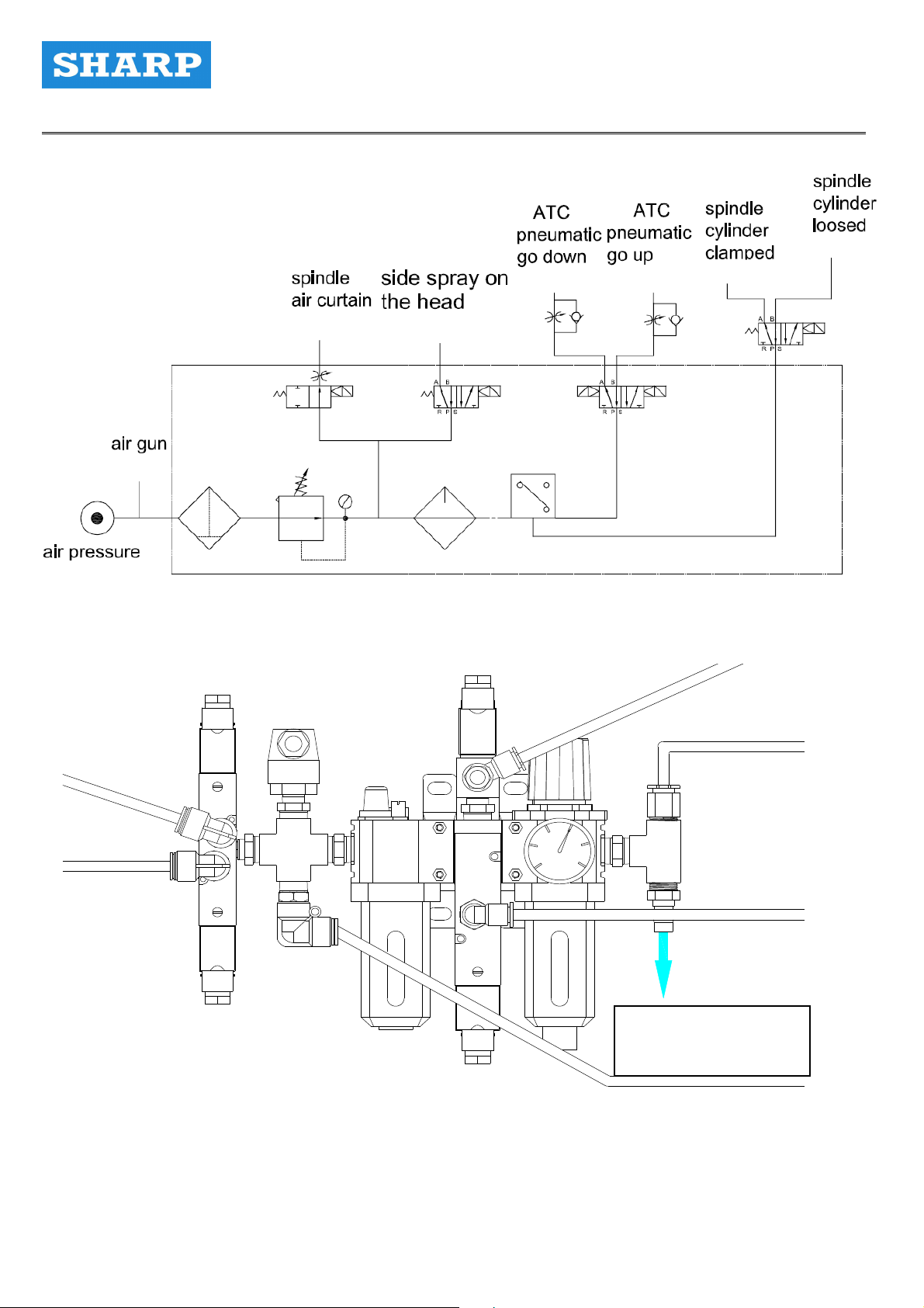
3-2 Air Compressor System Circuit Diagram
3-3 Air Compressor Unit
Connect to the air
pressure source
Page 24
24
PRECISION MACHINE TOOLS Ver2.1 Maintenance Manual
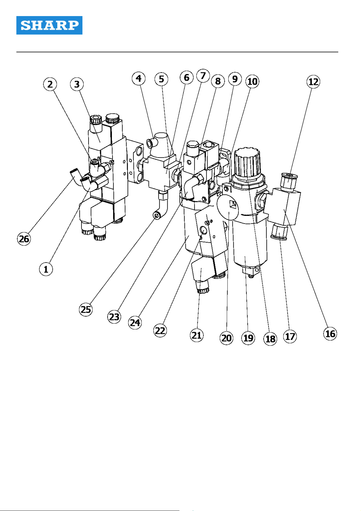
3-4 Air Compressor Detailed Specifications and Functions
Page 25
25
PRECISION MACHINE TOOLS Ver2.1 Maintenance Manual
Page 26

26
PRECISION MACHINE TOOLS Ver2.1 Maintenance Manual
Item
Name Size Qty.
L-shape extended
1
10mm_1/4" 1
brass connector
L-shape brass
2
10mm_1/4" 1
connector
1/4" 5/2-way_double
3 Solenoid valve
solenoid operated
4 Pressure detector 1/4" 1
5 Brass bushing 1/4"x3/8" 3
Copper female
6
thread four-way
3/8" 1
connector
Copper double
7
male thread
3/8" 1
connector
8 Solenoid valve 1/4" 2/2-way 1
1
9 Copper street elbow 1/4" 1
0
1/4" 2
10
Copper 90
double-male thread
connector
MACP300 T10
11 Connecting block
1
Quick straight
12
10mm_3/8" 1
connector
13 Straight connector 1/4"T*3/8"T 1
14 Air distribution block 1/4” * 2 1
MUSC-220-4E1-DC24
15 Solenoid valve
1
with lamp
Copper female
16
thread four-way
3/8" 1
connector
17 Quick connector 12mm_3/8" 1
Pressure regulating
18
MACP300-12A 1
valve
19 Water filtering cup MACP300-12A 1
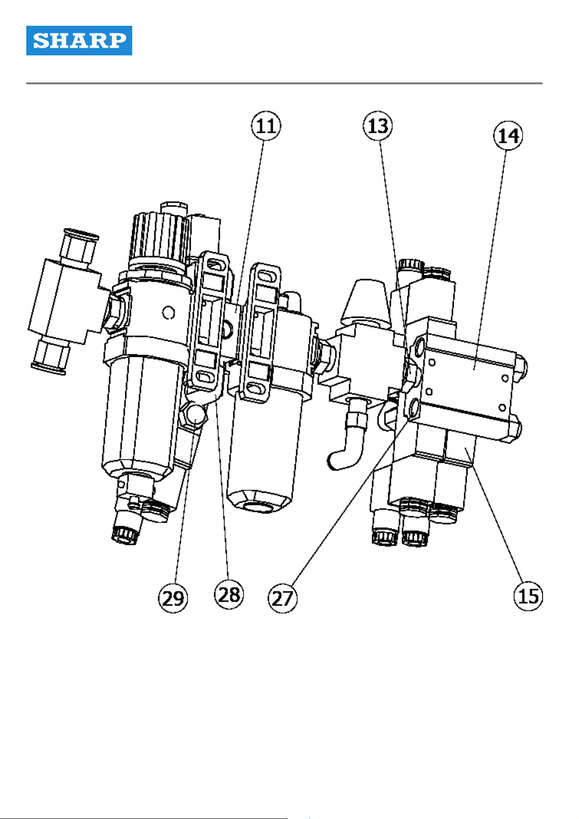
Page 27

27
PRECISION MACHINE TOOLS Ver2.1 Maintenance Manual
20 Pressure gauge 1.5" 10KG/PSI 1
21 Solenoid valve
1
solenoid operated
L-shape
3/8" 3/2-way_single
22
8mm_3/8" 1
compressor fitting
23 Throttle valve 8mm_1/4" 1
Lubrication pump oil
24
55cc MACP300-12A 1
cup
L-shape
25
10mm_3/8" 1
compressor fitting
Quick nylon-tube
26
10mm_1/4"*90° 1
connector
27 Hex head plug 1/4" 4
0
3/8" 1
28
Copper 90
double-male thread
connector
29 Muffler (flat) 1/4" 3
Page 28
28
PRECISION MACHINE TOOLS Ver2.1 Maintenance Manual
3-5 Air Compressor Unit Usage Instruction
1) The pressure source of this machine’s pressure pipeline goes through the air pressure preparation
unit, and the pressure is set to 6kg/cm2. When the pressure source is less than 5kg/cm2, and the
duration lasts more than 2 – 3 sec, NC will turn on the alarm, and CRT will display 1011 AIR
PRESSURE LOW. In this case, check the pressure source and then press the RESET button to
continue the operation.
2) Maximum pressure: 10kgf/cm²
3) Adjustment range: 0.5 ~8.7 Kg f/ cm²
4 ) Filter size:5μ
5 ) Recommended lube oil:ISO VG32
6) The pressure source should not be lower than: 5.5kgf/cm²
7) Although the air compressor preparation unit of the water filter has an automatically water
drainage, the machine operator should check whether there is any water accumulation at the shift or
at the end of the day. If the water drainage function is abnormal, water vapor may get into the air
compressor component, thereby reducing the lifespan. For the water drainage function of the filter to
be more effective, water in the air tank of the air compressor should fully drained out. It is also
recommended to install a dehumidifier at the pressure source to make sure that the air is dry.
8) The machine operator should pay attention to whether the pressure pipeline is making a bz kind of
noise. This may be due to gas leakage at the connector. Check the machine by tracing the noise.
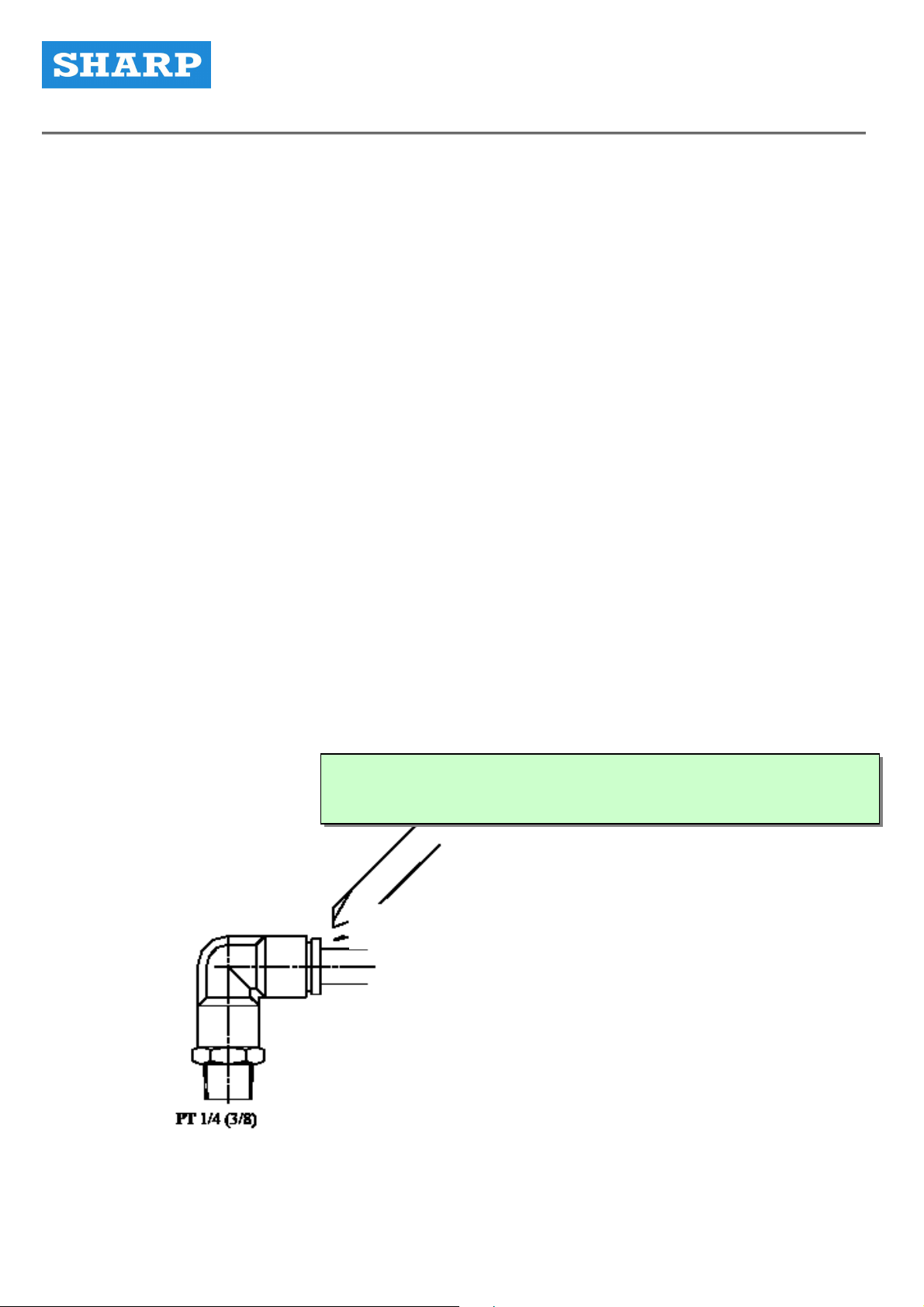
The pipeline of this machine is connected by connectors, and the disassembling method is
described below: The nylon tube can be directly inserted into the connector. Use the finger or a flat
screw driver to secure the connector when pulling out the nylon tube.
Use a screwdriver or fingers to press down the fixing ring.
Fixing ring
tube
Page 29

29
PRECISION MACHINE TOOLS Ver2.1 Maintenance Manual
3-6 Air Compressor Unit Troubleshooting
Problem Cause Correction
Reduced pressure source
output
Gas leakage
Disfunctional pressure
regulator
Output side air pressure low
Gas leakage at the screw cap
No oil dripped from the oil cup
The oil volume cannot be
adjusted
Oil leadkage at the adjustment
needle
Blocked filter Clean the filter
1. Loosened nut
2. Broken O-ring
3. Broken tube
Broken pressure regulator
1. Broken spring of the
pressure regulator
2. Broken spring of the valve
3. Dust or dirts on the base of
the valve
1. Tighten the nut
2. Replace the o-ring
3. Replace the tube
1. Replace the spring
2. Replace the spring
3. Clean the valve and the
base
4. Replace the valve
5. Replace the film
4. Broken lining of the valve
5. Broken film
1. Dust on the valve base
2. Broken inner lining rubber
3. Broken valve spring
1. Clean the valve and the
valve base
2. Replace the valve
3. Replace the spring
1. Loosened cap nut
2. Broken film
1. The adjusting needle being
too tight
2. The adjusting needle
cannot be closed or there
are dirts on the needle. The
adjustment needle cannot
bear the pressure
3. Broken or damaged
adjusting needle or needle
1. Tighten the cap nut
2. Replace the film
1. Loosen up the needle
2. Reduce the oil volume until
the level reaches the
maximum oil level
3. Add more oil until the level
reaches between the
maximum and the
minimum level
4. Clean up the blockage
base
1. The adjustment needle is
too loose
2. The adjustment needle
cannot be closed or dirt on
the needle. The adjusting
1. Tighteen the needle and
gradually loosen it for
adjustment
2. Remove the dirt
3. Partial replacement
needle cannot bear the
pressure
3. Broken or damaged
adjustment needle or
needle base
1. The needle is too loose
2. Broken O-ring
1. Tighten up the adjustment
needle
2. Replace the O-ring
Page 30

30
PRECISION MACHINE TOOLS Ver2.1 Maintenance Manual
Chapter 4
The Lubrication Unit
Page 31

31
PRECISION MACHINE TOOLS Ver2.1 Maintenance Manual
4-1 Centralized Lubrication System Diagram
1) Components of the lubrication oil pump
( a ) Flow rate:300cc / min
( b ) Voltage:220V ( 50 / 60 HZ )
( c ) Power:150W( d ) Maximum output pressure:15kg/cm²
( e ) Oil tank capacity:6L
Connections:
1、3:Electric source
2、3:Manual oil injection
4、5:Floating switch
6、7:Pressure in section
Page 32

32
PRECISION MACHINE TOOLS Ver2.1 Maintenance Manual
2) Lubrication System Diagram
Number Model Name Quantity
1. PA6 Pipe cape 3
2. PB6 Pipe 3
3. PKD6 3-way pipe 1
4. PH601 Right angle connector 2
caution:
1) Value of the input source current has to be the same as the one on the plague.
2) The wiring has to follow the instructions on the plaque to avoid damaging the oil pump.
3) Ground the ground wire.
4) A filter is installed on the inlet of the oil tank. Do not contaminate the manifold block
components.
5) Wash the filter whenever it is contaminated to maintain its function.
6) Do not drop oil, water or other onto the control circuit, or the control circuit may be
damaged.
7) Pay attention to the oil level when filling up the oil.
Page 33

33
PRECISION MACHINE TOOLS Ver2.1 Maintenance Manual
4-2 Spindle Bearing Lubrication
High quality lube oil is used for the spindle bearing, and it is good for high temperature and high
speed conditions. Its lubricating effect on the bearing is long-lasting without being too oily, and
therefore there is no need to add or to change the lube oil for a while. It is therefore cost-saving.
4-3 Guide way and Ball Screw Lubrication
The linear guide way of X, Y and Z axes and the ball screws are lubricated by a centralized
lubrication system which lubricates according to the set schedule.Machine operators must ensure
that the oiling machine has enough oil, as well as whether there is any abnormality.
1) Lead Screw Lubrication
The bearing of the lead screw can be divided into the motor end and the housing end. Lube oil is
applied onto both ends for oil sealing. If the oil goes bad, dissemble these parts to wash the bearing
and reassembling them. Please contact the Company to have professionals checkup and
modification for you.
Page 34

34
PRECISION MACHINE TOOLS Ver2.1 Maintenance Manual
2) Guide way Lubrication
Guide ways of the workbench (X-axis), the saddle (Y-axis), the head (Z-axis), ball screws of the three
axes (X, Y and Z axes) and the nuts are lubricated by the automatic centralized lubrication system in
which an oil pump is located at the back of the machine.
If the machine has not been operated for a long time, less lube oil will be available in the oil tube. For
the following cases:
1) A machine installed for the first time;
2) A machine has not been operated for a long time;
3) Before operating a machine (daily);
You should manually lubricate to ensure that sufficient lube oil has circulated the entire guide way.
Press the red button on the lube oil pump for about 40 sec before releasing the button. Wait for 10
sec to repeat the above procedure. Repeat this process until lube oil has leaked out from the guide
way.
Cautions:
The oil tank has a 6-L capacity. Add oil from the oil inlet each week (or when necessary). If the oil
level reaches the minimum oil level, the operation panel will issue an alarm message informing the
risk.
1) Add clean lube oil specified for the guide way through the oil inlet. Do not use other types of lube
oil.
The recommended oils are:
Mobil VACTRA 1
Shell TONNA T32
2) Lube oil level:
The level should be maintained between the maximum and the minimum oil level marked on the oil
tank. Once the level drops below the midpoint, add oil as soon as possible. Do not add oil only after
the alarm goes off, which can affect the operation of the machine.
Page 35

35
PRECISION MACHINE TOOLS Ver2.1 Maintenance Manual
SPINDLE HEAD UNIT
Number Model Name Quantity
1. PA6 Pipe cape 1
2. PB6 Pipe 1
3. PQ101 Connector 1
4. PH601 Straight angle connector 1
5. HBL-3 Volume-based distributor 1
6. PAN4 nut 7
7. PB4 Pipe 14
8. PA4 Pipe cape 7
9. PH4-1 Straight angle flat
connector
10. PG01 Sealing plug 1
7
Page 36

36
PRECISION MACHINE TOOLS Ver2.1 Maintenance Manual
WORK TABLE UNIT
Item Name Item Name
H Left front guide way surface A Right front guide way surface
G
E
F Left rear guide way surface D Right rear guide way surface
Left front reference surface
B
and pressure plate
Left rear reference surface
C
and pressure plate
Right front reference surface
and pressure plate
Right front reference surface
and pressure plate
Page 37

37
PRECISION MACHINE TOOLS Ver2.1 Maintenance Manual
Number
10. PA4 Pipe cape 9
11. PD401 Connector 8
12. HBL-5 Volume-based distributor 1
Saddle unit
Model Name Quantity
1. PH4-1 Flat and straight-angle connector 1
2. PB6 Pipe 7
3. JD6 Fixed dual connector 1
4. PH601 Straight-angle connector 3
5. PKD6 3-way pipe 1
6. HBL-4 Volume-based distributor 1
7. PQ01 Sealing plug 2
8. PAN4 nut 9
9. PB4 Pipe 18
Page 38

38
PRECISION MACHINE TOOLS Ver2.1 Maintenance Manual
Item
Name Item
A Left front embedded pressure plate I Right front embedded pressure plate
B Front left-right reference surface J Front right-right reference surface
C Front left-left reference surface K Front right-left reference surface
D Left front guide way surface L Right front guide way surface
E Left rear guide way surface M Right rear guide way surface
F Rear left-left reference surface N Rear right-left reference surface
G Rear left-right reference surface O Rear right-right reference surface
H Left front embedded pressure plate P Right front embedded pressure plate
Number Model Name Quantity
1. PKD6 3-way pipe 2
2. PB6 Pipe 8
3. PA6 Pipe cape 8
4. HBL-4 Volume-based distributor 1
Name
5. HBL-5 Volume-based distributor 2
6. PAN4 Nut 17
7. PB4 Pipe 34
8. PA4 Pipe cape 17
9. PH4-1 Flat and straight-angle connector
17
10. PH601 Straight-angle connector 2
11. HBL-3 Volume-based distributor 1
12. PQ101 Connector 2
13 PG01 Sealing plug 1
Page 39

39
PRECISION MACHINE TOOLS Ver2.1 Maintenance Manual
4-4 Lubrication of the Cam Box of Tool Magazine
Tool magazine’s rotation is driven by ACT cam box. To ensure a smooth rotation of the cam box, it
has to be routinely checked on whether there is enough oil for the oil lens. If not, add oil. After 2,400
hour of operation, replace the circulating oil in the cam box.
Oil inlet
Oil lens
4-5 Counterweight Chain and Sprocket Bearing Lubrication
Apply lube oil onto the sprocket of the counterweight chain. There is an oil inlet at the center of the
sprocket bearing. Add oil at least once a year. Lubricate the counterweight chain, too.
入油口
(oil in)
Page 40

40
PRECISION MACHINE TOOLS Ver2.1 Maintenance Manual
4-6 Cylinder Lubrication
1. Normally, oil in the oil cup will be depleted eventually. The oil will be used up after about 500,000
times.
2. Normally, it is recommended to remove the remaining oil from the oil cup each year and add new
one when doing the machine maintenance (dot not disassemble the oil cup, or it may be
damaged).
3. The color of the oil will be darkened if it has not been replaced for a long time. It will affect the air
pressure and lifespan of the machine. Check it routinely or monthly.
4. It is abnormal is the oil is depleted within 2 to 3 days. Check whether there is leakage at the oil cup
or the cup is broken. If so, replace the oil cup. If the depletion is abnormal, the boosting cylinder
may need to be replaced immediately to protect the spindle.
4-7 Lubrication Location
Page 41

41
PRECISION MACHINE TOOLS Ver2.1 Maintenance Manual
Chapter 5
The Spindle Oil Cooling Unit
Page 42

42
PRECISION MACHINE TOOLS Ver2.1 Maintenance Manual
5-1 Oil Cooling Pipeline Diagram
Page 43

43
PRECISION MACHINE TOOLS Ver2.1 Maintenance Manual
5-2 Spindle Oil Cooling Unit
a) Add the correct type of oil according to the instructions presented on the plaque.
b) The air filter of the cooling unit should be kept clean. It can be taken out for cleaning.
c) The cooling unit also has a oil filter, which has to be cleaned routinely.
Names and operation of functions on the small panel
Page 44

44
PRECISION MACHINE TOOLS Ver2.1 Maintenance Manual
The spindle has already been appropriately adjusted prior to the installation. It is normal to have a
slight increase of temperature. Spindle oil temperature is supplementary only; do not set the
temperature too high or too low. The temperature control mechanism for the cooler is base on
tracking temperature differences between the oil temperature and the room temperature (or the
machine temperature) to make sure that the difference is well maintained.
The cooling unit is turn on and off automatically based on the temperature of the machine. The
control key of the oil temperature is on the control panel of the cooling unit. When the SV is set to 0℃,
the oil temperature and the machine temperature are the same. When the SV is set to +℃,
temperature of the oil will be greater than of machine. When the SV is set to -℃, temperature of the
oil will be less than of the machine. In general, these two temperatures are set to be equal. If the oil
temperature is set to be lower than the machine temperature, temperature of the oil tank will be
smaller than that of the machine. In this case, condensation may occur, which could contaminate the
oil. Moreover, the external guide way of the bearing may shrink during the operation because the
level of fraction and temperature will be increased, which can damage the spindle.
Do not arbitrarily modify the default value.
Note: This machine has automatic fault detection. When any fault detected, the panel will flash and
display the fault signal. Troubleshooting is required. Then, turn off the machine for at least 10 sec
before turning it on again. For operation quality, double-check that all the problems have been
resolved and the system is at a good condition.
Page 45

45
PRECISION MACHINE TOOLS Ver2.1 Maintenance Manual
Page 46

46
PRECISION MACHINE TOOLS Ver2.1 Maintenance Manual
The oil filter shall be installed at the return oil ( inlet ) of the cooler to filter impurity efficiently and
protect the spindle.
Oil cooler uses hydraulic oil and lubrication oil. The directed oil for WEXTEN cooler is 2-300 CST.
The oil below are prohibited.
(1 ) Hydraulic oil of phosphoric ester and chlorinated hydrocarbon types, water, water/ glycol
hydraulic oil
( 2 ) Cutting oil, grinding oil and water-soluble liquid.
( 3 ) Medicine and corrosion liquid.
( 4 ) Gasoline , kerosene and EDM oil.
Check points before operation
1. When the power source is turned on, check to see if power lamp is lighted up.( see figure 1 )
2. Check that electrical resistance of compressor and pump is above 500 ohms.
3. Check that the oil level is at least at 80% level of the oil tank ( see figure 2 )
4. Check that the outlet of the oil tank is tightly secured.
5. Check that the overload switch is at “on “position.
6. Check that value is set at 5 kg/cm² for the pump pressure ( 5kg/cm² indicates 12 L/min, 20L/min,
30l/min pump adjust pressure; .5 kg / cm² indicates 4.5L/min, 7.5L/min, pump adjust pressure )
7. Check the high pressure switch of cooler of capacity 3000 kcal/hr is adjusted at 23 kg/cm² and
28 kg/ cm² for cooler of capacity above 6000 kcal/hr. ( see figure 3 )
8. Check if the oil inlet is fitted with an oil filter. ( see figure 4 )
9. Check cooling medium high/low pressure, if the indication needle position is as same as the
testing report
Page 47

47
PRECISION MACHINE TOOLS Ver2.1 Maintenance Manual
Page 48

48
PRECISION MACHINE TOOLS Ver2.1 Maintenance Manual
Troubleshooting
Possible Causes and Remedial Action
1. For any alarm signals, please refer to the following recommended remedial action.
If problems cannot be solved, please contact us or our nearest agent. Checking the cooler model,
sear number and the particular alarm sign show on control panel.
Lack of cooling medium
The following condition is caused by lack of cooling medium:
No alarm information but the motors keep running, cooler can not reach to the setting temperature
and working machine’s spindle is hot.
If the above situation occurred, please call professional technical staff to dispose or contact us
directly.
Oil tank and filter
1. Oil level in tank should be ay least at the 80% level mark to prevent the air into the pump. At the
same time, maintain the oil is clean.
2. The oil filter must be replaced or cleaned periodically, in order to prevent accumulating iron
powder to reduce the discharge rate of pump and cause noisy.
Note: Machine damaged due to not on a regular basis cleaned filter or unrelated return oil filter is
caused by human error, which is not covered by the warranty.
Page 49

49
t run or blades fall.
PRECISION MACHINE TOOLS Ver2.1 Maintenance Manual
Condition Cause Remedy
Power lamp is off
REV is lighted
OPS is lighted
1. LED burnt
2. PC board fuse blown
3. Transformer burnt
4. Wire 18,19 loose connection
1. 3 phase power reverse value 3 phase
is above ±10%
2. Pressure reduction and differential
1. Inlet oil pipe is clogged or loosened
2. Inlet & outlet are reversed
3. Pump motor runs reverse
4. Pump can not run
5. Circulation oil is not enough
6. Oil filter is dirty
7. Oil pressure switch breakdown
1. Overload relay is off
1. Replace PC board
2. Replace fuse
3. Replace transformer
4. Reconnect wire 18,19
1. Switch any 2 of the R.S.T wires
2. Stability power source
1. Check, clean and lock pipe
2. Correct position of in/outlet
3. Check over-relay of 51p red
and white lines.
4. Replace oil pump
5. Supply circulation oil
6. Replace new filter
7. Adjust oil pressure switch DIFF,
0.3 kgf/cm² range 0.8~0.8 cmHg
1. Reset switch
PUMP is lighted
2. Pump switch is off
3. Inlet pipe is clogged
1. Overload relay off
2. Reset pump switch
Clean pipe and replace oil filter
1. Reset switch
COM is lighted
2. Compressor breakdown
1. Condenser is too dirty
2. Air filter is not clean
3. Cooling fan doesn’
4. Cooling medium pressure switch
2. Replace compressor
1. Use compress air to clean fins
and restart cooler.
2. Clean filter.
3. Lock fan blades tightly or replace
HP is lighted
breakdown.
5. Cooling medium is leaking
fan motor.
4. Replace cooling medium
pressure switch.
5. Irrigate cooling medium.
RA is lighted 1. Room temp. sensor breakdown 1. Replace RA sensor
RO is lighted 1. Oil temp. sensor breakdown 1. Replace RO sensor
1. Oil temp. is to high
2. Temp. sensor blown
1. Stop running cooler until oil temp.
returns to normal range start again
OT is lighted
3. Check cooling medium is enough or
2. Replace temp sensor.
not.
3. Supply cooling.
Page 50

50
PRECISION MACHINE TOOLS Ver2.1 Maintenance Manual
Chapter 6The Electrical Unit
Page 51

51
PRECISION MACHINE TOOLS Ver2.1 Maintenance Manual
6-1 The Electrical Unit
1. Check the connectors of the electrical lines to prevent from detachment.
2. Make sure that the battery is replaced once a year to prevent parameter deletion, unstable
parameters or unstable three-axis positioning precision.
3. The dust cover of the electrical box and the filter of the thermal heat exchanger have to be kept
clean.
4. Operation environment conditions:
Low temperature
Good air circulation
Dry floor
Remote from electromagnetic disturbance
Stable electricity
5. Basic safe operation conditions: (See the following page)
Please follow the five basic rules below:
1. Only people know about this machine and have qualification as well as permission can operate
the machine or performance the maintenance. Those competent individuals have to receive
appropriate training to understand the safety and protective measures as well as machine
maintenance work. These individuals have to be approved for their safety control ability.
Especially those performing the electrical maintenance, they have to be experienced and can
recognize the safety standard and official regulations.
2. Before operating the machine, make sure that the safety instruction part as well as descriptions
on the operation, programs and maintenance in the user’s manual has been well read.
3. Individuals who need to operate the machine or give maintenance should know the emergency
stop button and the function.
Page 52

52
PRECISION MACHINE TOOLS Ver2.1 Maintenance Manual
1) Operation box
Note:
(a) Please well guard the relevant keys.
(b) The dust pan has two security keys.
To prevent the memory to be modified arbitrarily, use the function showed on the right figure.
Emergency stop:
Press this button to halt
the operation
immediately.
Memory edit lock:
This key is used to prevent unauthorized or
arbitrarily changing of the processing procedure.
Page 53

53
turn of this switch.
PRECISION MACHINE TOOLS Ver2.1 Maintenance Manual
2) Electrical box
(a) Please well guard the relevant keys.
(b) The machine has two security keys to prevent the electrical box from being opened arbitrarily.
The functions are presented on the right figure.
(c) Keep the user’s manual at an easily accessed location. If the manual word can’t read, please call
the agent and confirm the model as well as the model number of the machine.
Locked electrical box:
The box cannot be opened by
unauthorized personnel.
Main power switch:
Before performing and maintenance,
repair or for any emergency condition,
Page 54

54
PRECISION MACHINE TOOLS Ver2.1 Maintenance Manual
Chapter 7
Appendix
Page 55

55
less deterioration
Recommended
(3)CASTROL HYSPIN
PRECISION MACHINE TOOLS Ver2.1 Maintenance Manual
7-1 Oil Selection
Lubrication
Location
Characteristics
of the oil
Lubrication
Methods
Oil
Air Compressor
Preparation Unit
(1) Viscosity ISO
VG32
(2) Anti rust,
foam, oxidation,
etc.
(3) Good stability;
Guide ways and balls
screw
(1) ISO VG32
(2) High oil film
intensity
(3) Low abrasion
(4) High abrasion
resistance
Cylinder Coolant
(1) Viscosity ISO
VG68
(2) Anti rust,
foam, oxidation,
and
emulsification
(5) High thermal
stability
(6) High corrosion
resistance
(7) High rust
resistance
Oil feeder Automatic centralized
Circulation
lubrication
When needed When needed Add more when
(1) High thermal
conduction
2) Good lubrication
When needed
replacement
interval
needed; replace
the oil every
year.
Tank capacity 55CC 3L 270L
Brands
(1)MOBIL
RARUS 424
(2)ESSO
TERESSO S32
(3)CASTROL
HYSPIN VG32
(4)SHELL
TONNA S32
(1)MOBIL VACTRA 1
(2)ESSO FEBIS K32
(3)CASTROL MAGNA
GC32
(4)Shell TONNA T32
(1)MOBIL
RARUS 424
(2)ESSO
TERESSO S32
(3)CASTROL
HYSPIN VG32
(4)SHELL
TONNA S32
(1)MOBIL RARUS
(2)ESSO TERESSO
(4)SHELL TONNA
424
S32
VG32
S32
Page 56

56
PRECISION MACHINE TOOLS Ver2.1 Maintenance Manual
7-2 Spindle Tool Change Position Calibration
1) Check whether the origin offset of the Z-axis is zero. Change the positive and negative move
distance of the Z-axis to 99999999 and -99999999. Afterward, return the Z-axis to zero position .
Put a cutter on the spindle. Measure 0.6~ 0.8 mm the distance of tool unclamp .
Then, remove the cutter.
2) Lock the tool calibration magazine module onto the body of the tool magazine
Tool magazine calibration
module
(Adjustment block)
Page 57

57
PRECISION MACHINE TOOLS Ver2.1 Maintenance Manual
3) Take out a modular concentricity test gauge and a dial indicator. Separate the three sections and
place them on the inner hole of the spindle and gripper.
Dial indicator
Gripper
Arm
Modular concentricity test gauge
4) Use the dial indicator to measure the position of the arm of the cutter.
The X-axis deviation should not exceed 0.1mm.
5) Fasten the screws (circled by a red line) according to the ISO standard.
6) Hammer the tool magazine into the fixing pin (circled by a yellow line
Fixing pin for the tool magazine
Fixing screw for the tool magazine
Fixing screw for the tool magazine
Page 58

58
PRECISION MACHINE TOOLS Ver2.1 Maintenance Manual
7-3 Determination of the Z-Axis Coordinate Origin
Shift the Z-axis from the nose end of the spindle to a position that is 130mm above the workbench.
See the figure below.
Nose end of the spindle
130mm
2.
1) Treat this position as the origin. Zero the value corresponded to the Z-axis on the screen.
2) Shift the Z-axis to a position where the corresponding position on the screen is
740mm.
Page 59

59
PRECISION MACHINE TOOLS Ver2.1 Maintenance Manual
4. At this point, the relative distance between the spindle nose end and the workbench is 740mm.
See the figure below.
740 mm
Page 60

60
PRECISION MACHINE TOOLS Ver2.1 Maintenance Manual
4. Enter the parameter setup mode and look for 1815. Change the APZ of the Z-axis to 0 before
turning on the machine.
5. After turning on the machine, enter Parameter 1815 to change APZ of Z-axis to 1. Turn on the
machine again (At this point, the position of the Z-axis will be treated as the machine reference
point).
Page 61

61
PRECISION MACHINE TOOLS Ver2.1 Maintenance Manual
7-4 Descriptions on Program and Servo Alarms
Page 62

62
PRECISION MACHINE TOOLS Ver2.1 Maintenance Manual
Page 63

63
PRECISION MACHINE TOOLS Ver2.1 Maintenance Manual
Page 64

64
PRECISION MACHINE TOOLS Ver2.1 Maintenance Manual
Page 65

65
PRECISION MACHINE TOOLS Ver2.1 Maintenance Manual
Page 66

66
PRECISION MACHINE TOOLS Ver2.1 Maintenance Manual
Page 67

67
PRECISION MACHINE TOOLS Ver2.1 Maintenance Manual
Page 68

68
PRECISION MACHINE TOOLS Ver2.1 Maintenance Manual
Page 69

69
PRECISION MACHINE TOOLS Ver2.1 Maintenance Manual
Page 70

70
PRECISION MACHINE TOOLS Ver2.1 Maintenance Manual
Page 71

71
PRECISION MACHINE TOOLS Ver2.1 Maintenance Manual
Page 72

72
PRECISION MACHINE TOOLS Ver2.1 Maintenance Manual
Page 73

73
PRECISION MACHINE TOOLS Ver2.1 Maintenance Manual
Page 74

74
PRECISION MACHINE TOOLS Ver2.1 Maintenance Manual
Page 75

75
PRECISION MACHINE TOOLS Ver2.1 Maintenance Manual
Page 76

76
PRECISION MACHINE TOOLS Ver2.1 Maintenance Manual
Page 77

77
PRECISION MACHINE TOOLS Ver 2 Maintenance Manual
Page 78

78
PRECISION MACHINE TOOLS Ver2.1 Maintenance Manual
Page 79

79
PRECISION MACHINE TOOLS Ver2.1 Maintenance Manual
Page 80

80
PRECISION MACHINE TOOLS Ver2.1 Maintenance Manual
Page 81

81
PRECISION MACHINE TOOLS Ver2.1 Maintenance Manual
Page 82

82
PRECISION MACHINE TOOLS Ver2.1 Maintenance Manual
Page 83

83
PRECISION MACHINE TOOLS Ver2.1 Maintenance Manual
Page 84

84
PRECISION MACHINE TOOLS Ver2.1 Maintenance Manual
Page 85

85
PRECISION MACHINE TOOLS Ver2.1 Maintenance Manual
Page 86

86
PRECISION MACHINE TOOLS Ver2.1 Maintenance Manual
Page 87

87
PRECISION MACHINE TOOLS Ver2.1 Maintenance Manual
Page 88

88
PRECISION MACHINE TOOLS Ver2.1 Maintenance Manual
Page 89

89
PRECISION MACHINE TOOLS Ver2.1 Maintenance Manual
Page 90

90
PRECISION MACHINE TOOLS Ver2.1 Maintenance Manual
Page 91

91
PRECISION MACHINE TOOLS Ver2.1 Maintenance Manual
Page 92

92
PRECISION MACHINE TOOLS Ver2.1 Maintenance Manual
Page 93

93
PRECISION MACHINE TOOLS Ver2.1 Maintenance Manual
Page 94

94
PRECISION MACHINE TOOLS Ver2.1 Maintenance Manual
Page 95

95
PRECISION MACHINE TOOLS Ver2.1 Maintenance Manual
Page 96

96
PRECISION MACHINE TOOLS Ver2.1 Maintenance Manual
Page 97

97
PRECISION MACHINE TOOLS Ver2.1 Maintenance Manual
Page 98

98
PRECISION MACHINE TOOLS Ver2.1 Maintenance Manual
Page 99

99
PRECISION MACHINE TOOLS Ver2.1 Maintenance Manual
Page 100

100
PRECISION MACHINE TOOLS Ver2.1 Maintenance Manual
 Loading...