

Page 1
PRECISION MACHINERY TOOLS VER.2 Operator’s Manual
OPERATION MANUL
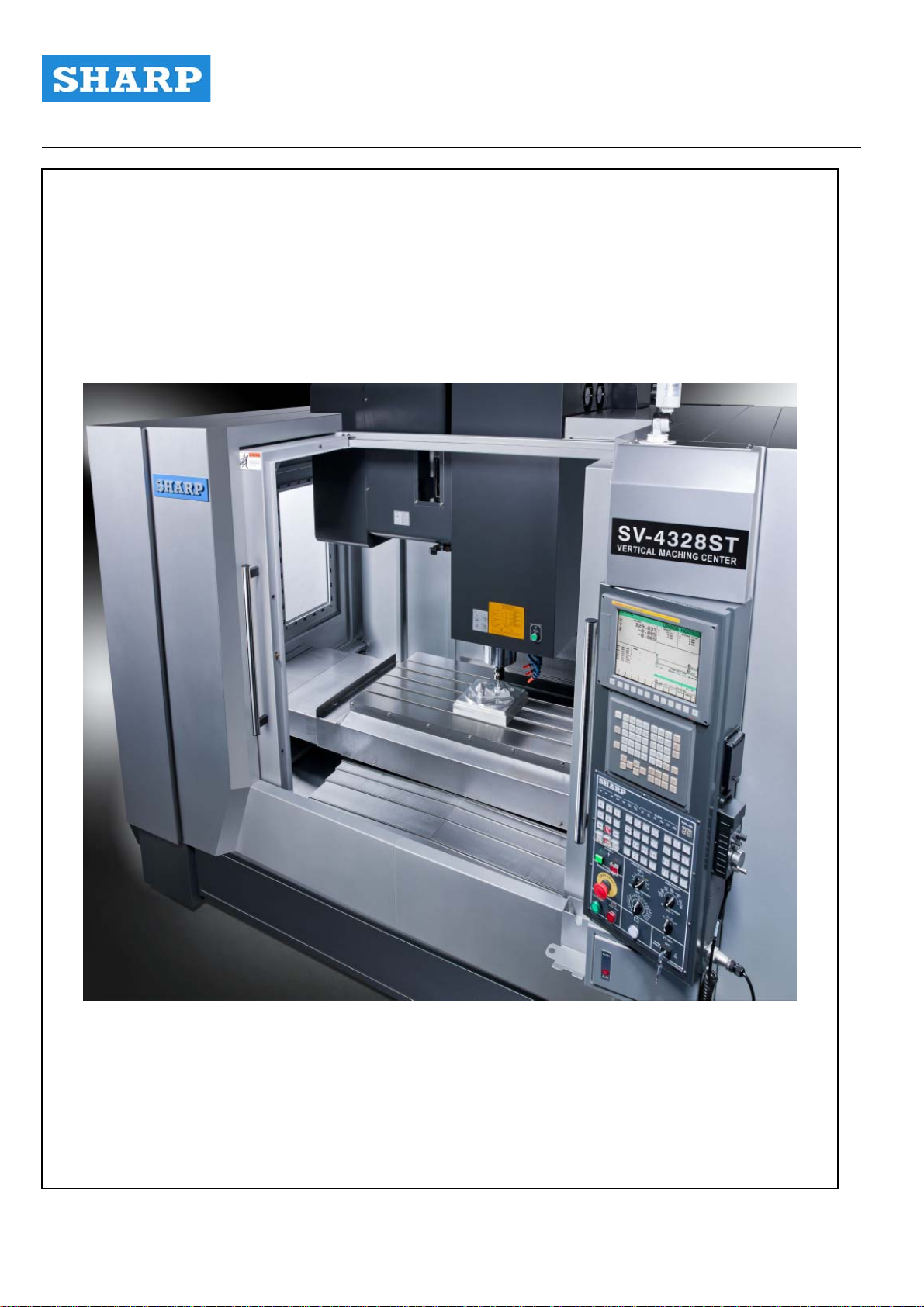
SV-4328ST
FVL-01E-02
FVL-01E-02
1
Page 2

PRECISION MACHINERY TOOLS VER.2 Operator’s Manual
Chapter 1 SAFETY
1.1 Safety Precautions 10
1.2 Warning Labels 10
1.3 Utilization Of Safety Device 16
1.4 Warning Lists 17
Chapter 2 Preparations For Installation
Overview 22
1. Preparation Of Set-up Area 23
2. Preparation Of Transport Route 27
3. Preparation Of Transportation Equipment 28
4. Set-up Conditions 29
5. Air/Power Sources 30
6. Recommended Foundations 32
Chapter 3 OPERATION
Before Starting Operation / Operation Flowchart 36
1. Main Operation Panel 37
1.1 Main Operation Panel Functions 37
1.2 LCD Control Panel Functions 57
1.3 Displaying PC Screen 61
2. M_CODE
2.1 M-code List
3. Setting/Changing Machine Parameters 66
4. Opening / closing Doors 70
4.1 Opening / closing Splashguard Door 70
5. Turning On/Off Power Supply 73
6. Data Registration / Editing 76
6.1 NC Program Registration ( 3 Methods ) 76
6.2 Tool Offset Registration 76
6.3 Tool Offset Value 79
64
64
6.4 Registration Of Workpiece Offset Value 80
7. Workpiece Attachment And Detachment 84
1. Workpiece Attachment And Detachment 84
2. Workpiece Restrictions 85
2
Page 3

PRECISION MACHINERY TOOLS VER.2 Operator’s Manual
8. Tool Preparations 86
8.1 Tool Attachment and Detachment 86
8.2 Tool Storage Limitations 87
8.3 Tool And Retention Stud Combinations 87
9. Tool Change 91
10. Cutting Fluid Supply 92
11. Chip Disposal 93
11.1 Operation Of Lift-Up Conveyor 94
12. Automatic Operation 95
1. Program Edit Procedure 95
2. Program Configuration 96
3. Subprogram Call 98
4.Major Function And Address 100
5. Force Mirror Image 101
6. Program Edit 102
7. Add New Program 102
8. Delete Program 103
9. Program commanded Search 104
10. Edit key 105
11. Copy Program 11 0
12. Graphic Function 116
Chapter 4 PROGRAMMING
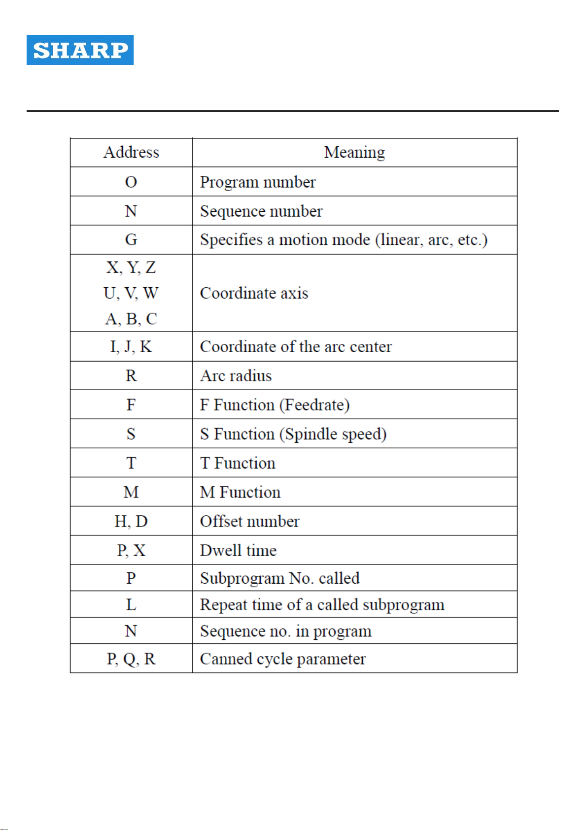
1. Commanded Description 136
1.1 G Commanded 136
1.2 F Commanded
1.3 S Commanded 141
1.4 T Function 144
1.5 G Code Composition 144
141
3
Page 4

PRECISION MACHINERY TOOLS VER.2 Operator’s Manual
Chapter 5 PROGRAM INPUT / OUT OPERATION
1. Memory Card Operation 213
1.1 Displaying The Directory 213
1.2 Searching for a File 214
1.3 Reading A File 216
1.4 Writing Files 218
1.5 Deleting A File 221
1.6 DNC Operation 222
1.6.1 Searching for a File 222
1.6.2 Executing A File 223
2 . Data Input/Output On The All I/O Screen 224
2.1 Program Input/Output 224
2.1.1 Program Input/Output 224
2.1.2 Searching For A File 225
2.1.3 Inputting A Program 227
2.1.4 Outputting Programs 229
2.1.5 Deleting A File 231
2.2 Parameter Input/Output 232
2.2.1 Searching For A Parameter 232
2.2.2 Inputting A Parameter 233
2.1.3 Outputting Parameters
2.1.4 Deleting A Program 236
235
Chapter 6 CUTTING TOOL CONDITION LIST
1. Cutting Tools use Description 237
1.1 Face Mill
1.2 End Mill 239
1.3 Boring Bar 240
1.4 Drill 241
1.5 Reamer 242
238
1.6 Tap 273
4
Page 5

PRECISION MACHINERY TOOLS VER.2 Operator’s Manual
Chapter 7 PARTS MANIUL
1. Spindle head 245
2. Column 247
3. Base 250
4. Saddle & Table 252
5. Lubrication 255
5.1 Saddle Distributor 255
5.2 Table Distributor 256
5.3 Spindle Distributor 257
5.4 Auto lubrication system 258
5.5 List of recommended lubricants for parts 259
6. Spindle 260
7. Magazine 267
1. main body 268
2. Tool disk 271
3. Cylinder mounting plate 271
4. Arm Body 272
5. Cambox 275
8. Pneumatic system 279
5
Page 6

PRECISION MACHINERY TOOLS VER.2 Operator’s Manual
MACHINE TYPE
MACHINE SERIAL #
CONTROL TYPE
ALL RIGHTS RESERVED . NO PART OF THIS DOCUMENT MAY BE REPRODUCED, COPIED,
OR MODIFIED IN ANY FORM OR ANY MEASNS WITHOUT DIRECT PERMISSION OF SHARP
MILLING MACHINES.
ALL SPECIFICA TIONS AND DESIGNS ARE SUBJEC TO CHANGE WITHOUT NOTIFICATION.
6
Page 7

PRECISION MACHINERY TOOLS VER.2 Operator’s Manual
INTRODUCTION
This manual is for this vertical machining center
Read this manual prior to beging any maintenance or repair work .
Follow the intructions provided in this manual to ensure the safty of those maintaining
or repairing this machine .
Disregarding or not following the specific directions in this manual may lead to serious
Injury or death .
7
Page 8

PRECISION MACHINERY TOOLS VER.2 Operator’s Manual
IMPORTANT NOTICE
1. Read and undertant Chapter “1. SAFETY ” prior
to machine operation to ensure safe working Conditions.
2. Designate specific operators for this machine to ensure
optimum machine perfrmance and safety standards are
maintained at all times .
3. Keep this manual in a clearly marked location to ensure
Easy access when necessary .
4. Contact the regional SHARP office or local distributor if
this manual is lost or damaged .
5. Reproduction of this manual in part or in its entirety is
prohibited by SHARP .
6. Ensure this in included when moving or reseling this
machine .
7. All spcifications and designs are subject to change without
prior notification .
SYMBOLS IN THIS MANUAL
Supplementary expianations
Explains operation erros that will cause
Alarme or stop the machine .
Explains convenient functions to be
used during operations .
Indicates reference items, figures and
tables providing futher information
8
Page 9
PRECISION MACHINERY TOOLS VER.2 Operator’s Manual
Chapter 1
Chapter 1 SAFETY
9
Page 10

PRECISION MACHINERY TOOLS VER.2 Operator’s Manual
Chapter 1
1.1 Safety Precautions
Safety precautions and special considerations relevant
to all machining operations must be thoroughly
understood by the operator prior to machine operation .
Careless use of the machine may result in serious
Injury and machine damage .
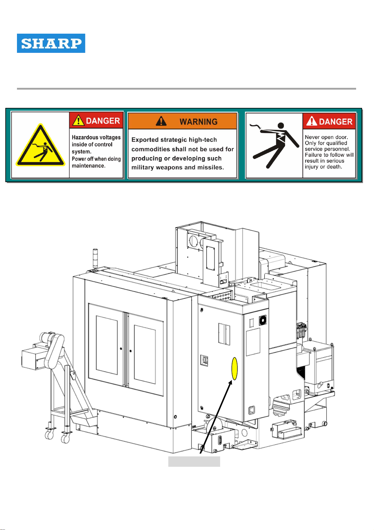
1.2 Warring Labels
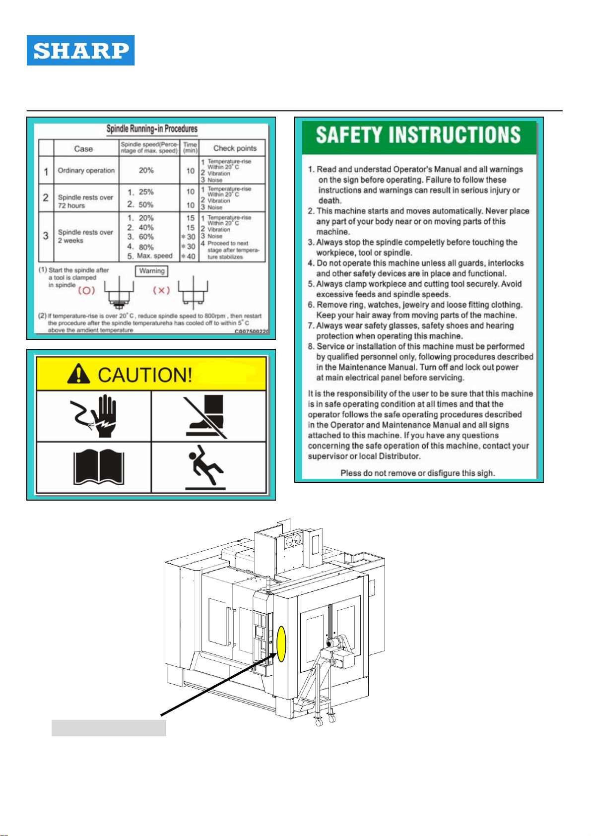
The warring labels attached to machine at specific points
identify safety risks and provide important instructions
that must be followed ( Figure 1.1 ~ Figure 1.5 )
Warning labels are divided into 3 categories according to
levels of caution required ( Table 1.1 )
Table 1.1 DANGER / WARNING STATEMENTS
Order new labels from the nearest sales office and affix in original position
Failure to heed this warning will
Lead to death or serious injury .
Failure to heed this warning may
cause working conditions Lead to
death or serious injury .
Failure to heed this warning may
cause working conditions Lead to
minor injury or machine damage
after the following:
․When the warning labels peel off
․When the warning labels become illegible
․When the parts on which the warning labels are attached are replace .
10
Page 11
PRECISION MACHINERY TOOLS VER.2 Operator’s Manual
Chapter 1
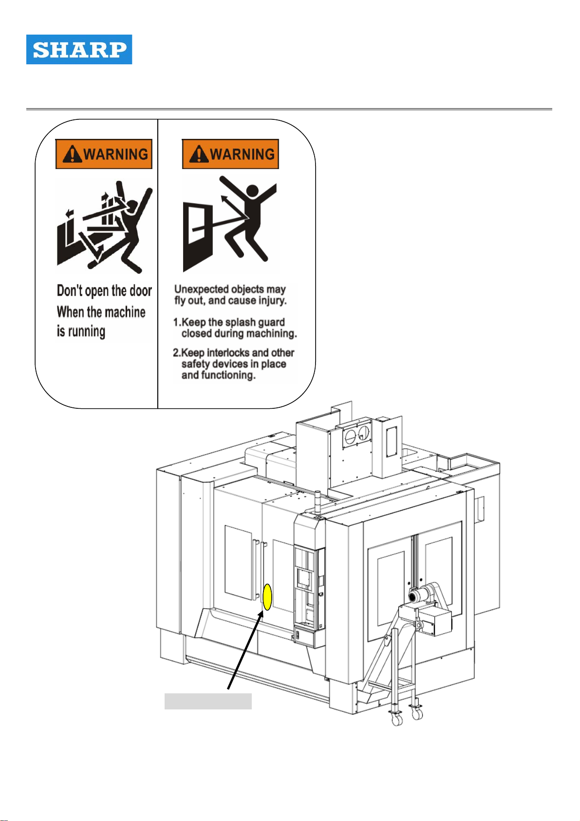
Operator Door
Figure 1.1 LOCATION OF WARNING LABEL
11
Page 12
PRECISION MACHINERY TOOLS VER.2 Operator’s Manual
Chapter 1
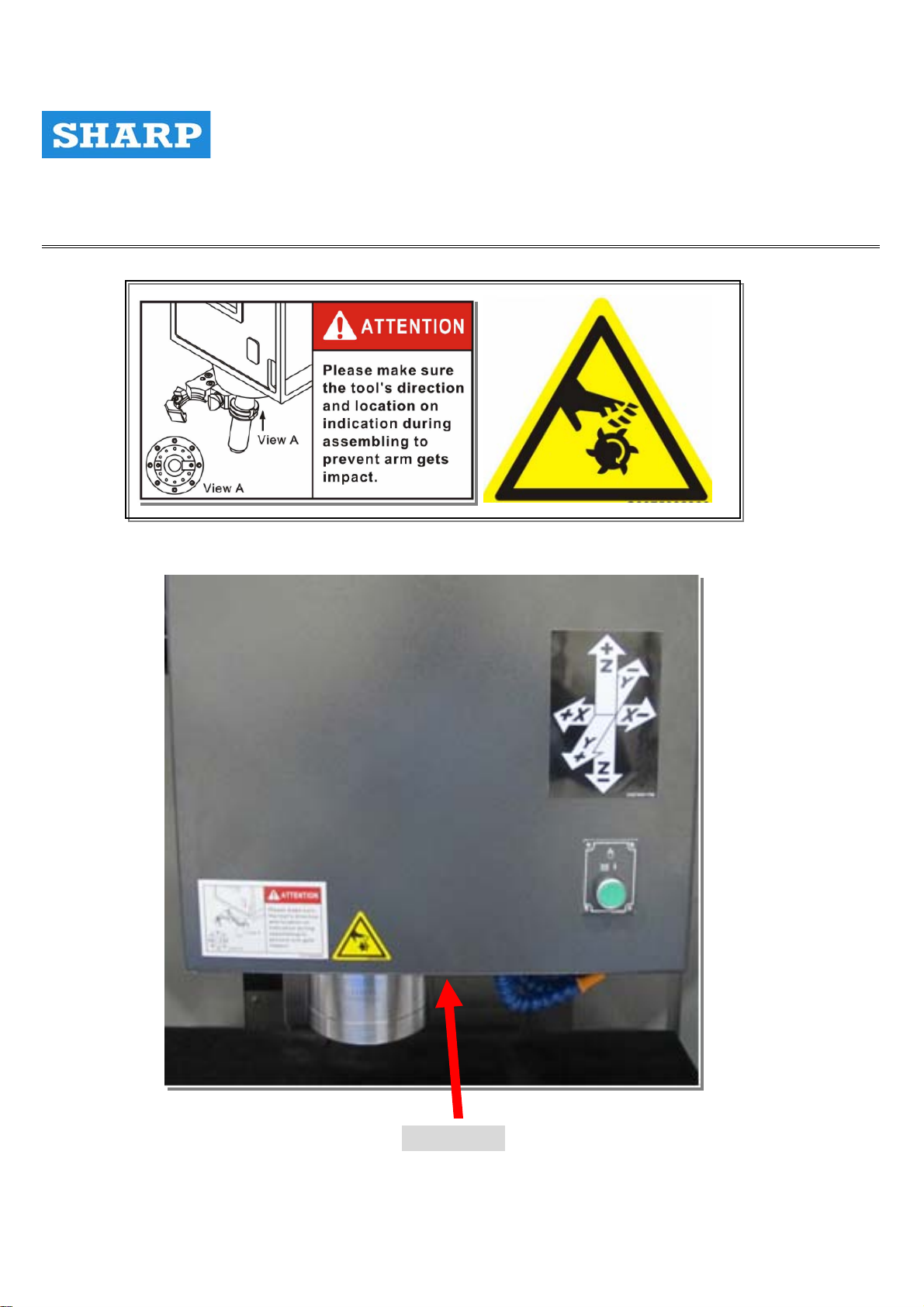
Operation Box side
Figure 1.2 LOCATION OF WARNING LABEL
12
Page 13
PRECISION MACHINERY TOOLS VER.2 Operator’ s Manual
Chapter 1
ETC Box side
Figure 1.3 LOCATION OF WARNING LABEL
13
Page 14
PRECISION MACHINERY TOOLS VER.2 Operator’ s Manual
Chapter 1
Figure 1.4 LOCATION OF WARNING LABEL
Head cover
14
Page 15
PRECISION MACHINERY TOOLS VER.2 Operator’ s Manual
Chapter 1
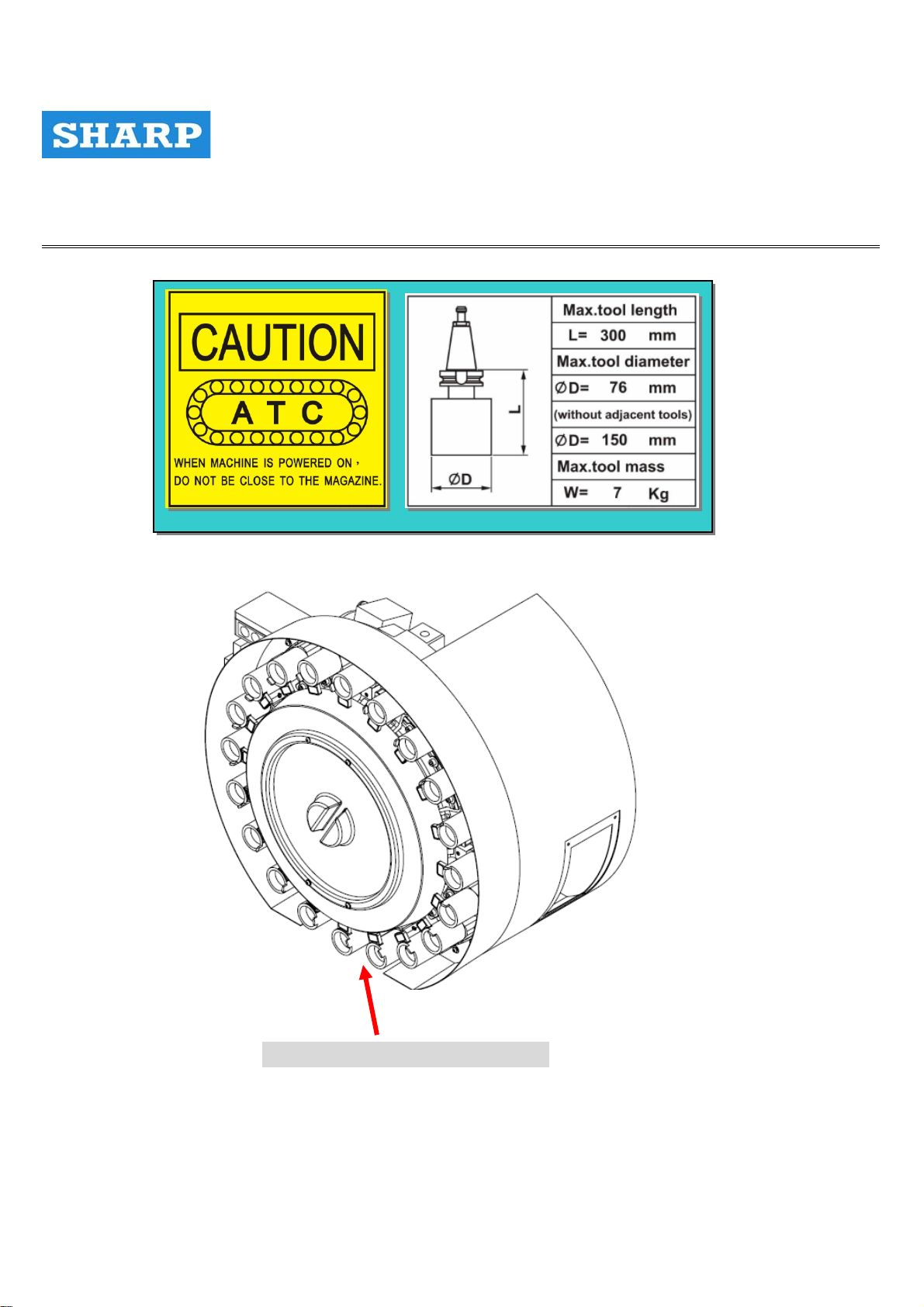
MAGAZINE FRONT COVER
Figure 1.5 LOCATION OF WARNING LABEL
15
Page 16
PRECISION MACHINERY TOOLS VER.2 Operator’ s Manual
Chapter 1
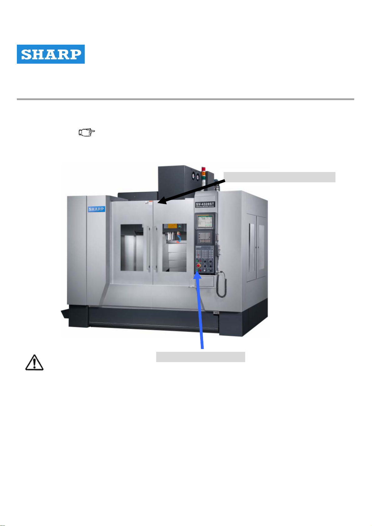
1.3 Utilization of safety devices
Safety devices ( Figure 2.1 ) are installed on this machine in order to protect operators and
Maintenance personnel .
Operation Door Safety Guard
Emergency Stop Button
Warning
․Confirm machine safety devices are function correctly at all times .
․If a safety devices is not functioning , or is functioning incorrectly , repair or replace immediately .
․Ensure all operators know the locations of the emergency stop buttons before operating
the machine to enable immediately use un abnormal situations or following an accident .
․Never place objects on the safety guards .
․Heed the following safety precautions at all times when operating the machine with
guards open:
→ Do not touch rotating or moving parts .
→ Do not touch each axis while in motion .
→ Exercise extreme care around parts that may be about to move .
16
Page 17

PRECISION MACHINERY TOOLS VER.2 Operator’ s Manual
Chapter 1
1.4 Warning lists
The following tables list frequent accidents , incidents and dangerous or careless operating
Conditions , and the injuries that may result .
Ensure the contents of each table are thoroughly understood prior to machine operation .
1.4.1Inside of machining chamber
Operations:Centering , alignment , workpiece loading / unloading, changing coolant nozzle,
direction, lighting replacement , chip removal, table lubrication, tool attachment /detachment .
ACCIDENT / INCIDENT PROTENTIAL INJURIES / DAMAGE
Operator touches rotating spindle
Operator touches bladed tools Cuts , injuries to hands
Operator lifts heavy tools Strained back
Operator stands on center-trough conveyor or
the surrounding splash guard and slips .
Feed axis moves , trapping operator in
machine
Operator is struck by ATC Arm Bone fracture
Operator is struck by chips and cutting fluid
scattered during machine .
Operator is splashed by cutting fluid dripped
from ceiling .
Hand(S) caught when closing S/ G door Bone fracture
Spindle is rotated with a tool incorrectly
clamped while door is open .
Amputation or entanglement of hand(s)
resulting in serious injury
Bone fracture
Bone fracture
Damage to eyes or cuts / burns to skin
Damage to eyes
Injury or death
Spindle is rotated prior to cleaning of tapered
section while door is open
Spindle is rotated with a bladed tool incorrectly
mounted while door is open .
Unblance tools are rotated at high speed while
door is open.
Injury or death
Injury or death
Injury or death
17
Page 18

PRECISION MACHINERY TOOLS VER.2 Operator’ s Manual
Chapter 1
1.4.2Tool Magazine , Tool Magazine Door
Operations:Tool replacement and lubrication
ACCIDENT / INCIDENT PROTENTIAL INJURIES / DAMAGE
Operator touches bladed tools Cuts or puncture injuries to hands
Operator lifts heavy tools Strain back
T-serch or tool change is commanded when
tool is incorrectly stored in pot
T-search or tool change is commanded when
tool blade is mounted incorrectly .
Operator works on oily floor Bone facture , injury cause by falling
Operator enters tool magazine without turning
OFF machine power
Operator insert hand into tool magazine
during operation
Injury or death
Injury or death
Injury or death
Cuts to hands or bone fractures
1.4.3 Cutting Fluid, Chips, Cutting Fluid Supply Unit, and Chip Disposal Unit
Operations:Regular machining , cutting fluid replenishment , tank cleaning , filter replacement .
ACCIDENT / INCIDENT PROTENTIAL INJURIES / DAMAGE
Operator inhales large quantities of cutting fluid mist . Respirator organ damage
Insufficient cutting fluid . Fire
Contact with chemical additives . Skin damage .
Operator inserts hands into conveyor or tank without
Turning OFF machine power
Operator cleans machine without wearing protective
glove .
Filter is replace without prior cleaning Cuts or puncture injuries to hands
Operator works on top of the machine when anchor bolts
are used incorrectly and machine is unstable .
Contact with cutting fluid . Skin irritation
Entanglement of hands resulting in
serious Injury .
Cuts or puncture injuries to hands
Bone fracture ; injury caused by falling
1.4.4 Signal lamp
Operations:Signal lamp bulb replacement
ACCIDENT / INCIDENT PROTENTIAL INJURIES /DAMAGE
Working in elevated locations . Falling , bone facture
18
Page 19

PRECISION MACHINERY TOOLS VER.2 Operator’ s Manual
Chapter 1
1.4.5 Spindle Coolant Oil
Operations:cleaning
ACCIDENT / INCIDENT PROTENTIAL INJURIES /DAMAGE
Oil temperature exceeds flashpoint .
Flashpoint of spindle coolant oil (VG32 ):
Approximately 20℃
Inappropriate operating methods Fluids may damage eyes or skin or be
Fire
accidentallyingested or inhaled by operator .
1.4.6 Machine Surrounding Area.
ACCIDENT / INCIDENT PROTENTIAL INJURIES /DAMAGE
Cables and piping are exposed on the floor . Falling
1.4.7Electric System.
ACCIDENT / INCIDENT PROTENTIAL INJURIES /DAMAGE
Operation without turning OFF main power switch .
Improper wiring
Loosening of screws in terminal block
Electric shock, machine malfunction,
abnormal operation, or fire
Machine malfunction, abnormal operation,
or fire
Machine malfunction, abnormal operation, or
fire
Door of machine controller and cover of terminal
box are left open .
Damage to cables on floor surrounding the machine
19
Electric leak, machine malfunction,
abnormal operation, or fire
Electric leak, machine malfunction,
abnormal operation, or fire
Page 20

PRECISION MACHINERY TOOLS VER.2 Operator’ s Manual
Chapter 1
1.4.8 Parameters.
ACCIDENT / INCIDENT PROTENTIAL INJURIES /DAMAGE
An NC or machine parameter not outline in this
manual is change
Before performing maintenance on the servo amp, spindle amp, turn off the machine power
stop
High voltage current flows through components inside the terminal box .
High voltage current continues to flow on the primary side of the main power switch
even after the switch is turned off .
Electrical current continues to flow to lamps outlets in the machine controller even after
the main power switch us turned off .
switch and confirm that the red LED indicator( charged ) for each device is extinguished .
Serious injury or death, damage to workpiece
or machine .
20
Page 21
PRECISION MACHINERY TOOLS VER.2 Operator’ s Manual
Chapter 2
Chapter 2
PREPARATIONS_FOR_INSTALLATION
21
Page 22

PRECISION MACHINERY TOOLS VER.2 Operator’ s Manual
Chapter 2
OVERIEW
Prior to machine installation, perform the following preparations to ensure all installation conditions
are satisfied :
Preparation of set-up area .
Preparation of transport route .
Preparation of transportation equipment .
Set-up conditions
Air / power sources
Recommended Foundations
Machine installation is to be performed
by specialized personnel only .
22
Page 23
PRECISION MACHINERY TOOLS VER.2 Operator’ s Manual
Chapter 2
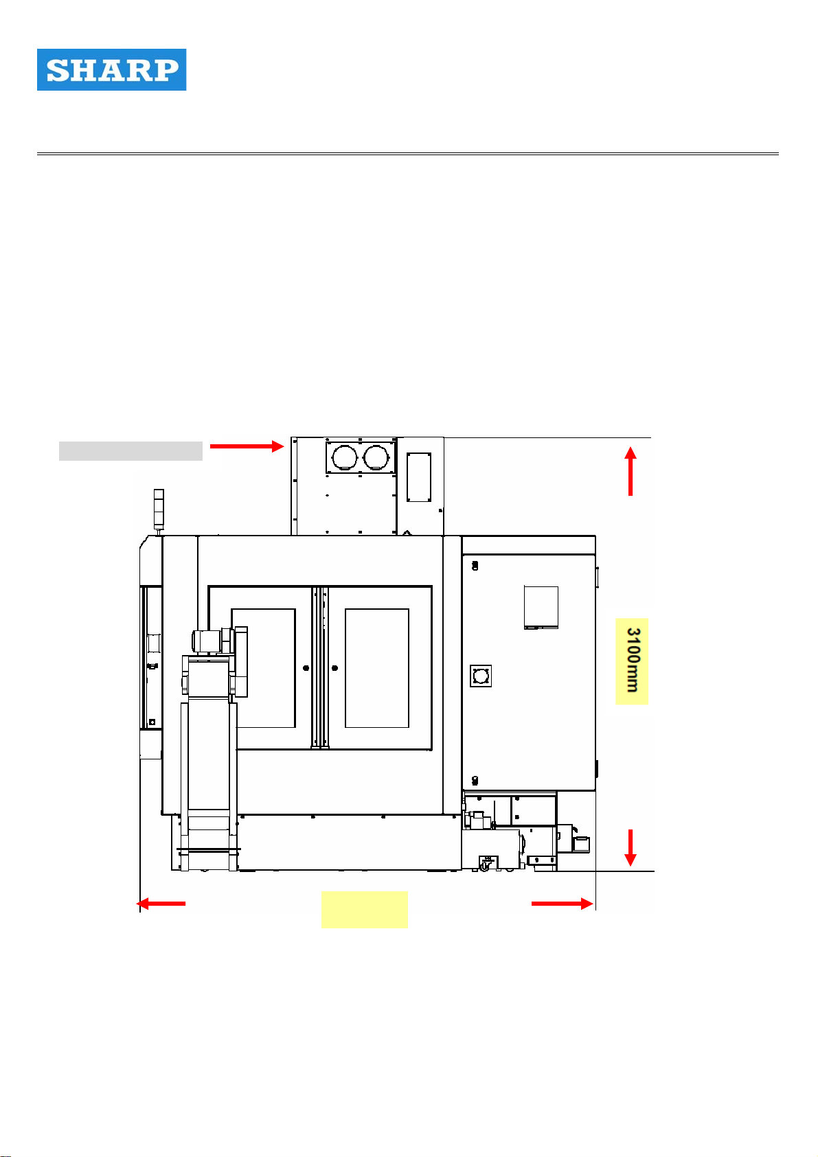
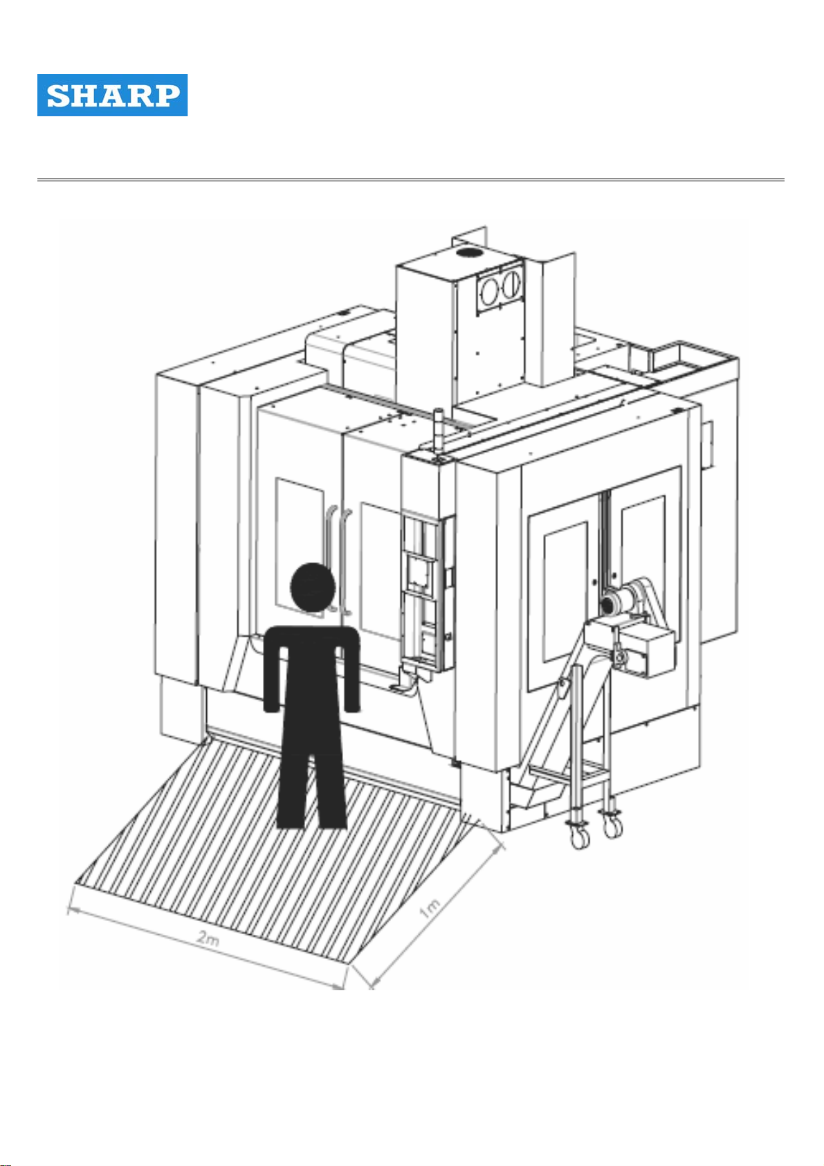
1. PREPARATION OF SET-UP AREA
Prior to installation, confirm spacing requirements .
Maintenance area refers to the maintenance space required after installation .
Maintenance Height
Figure 1.1 SIDE VIEW OF MACHINE
2825mm
23
Page 24
PRECISION MACHINERY TOOLS VER.2 Operator’ s Manual
Chapter 2
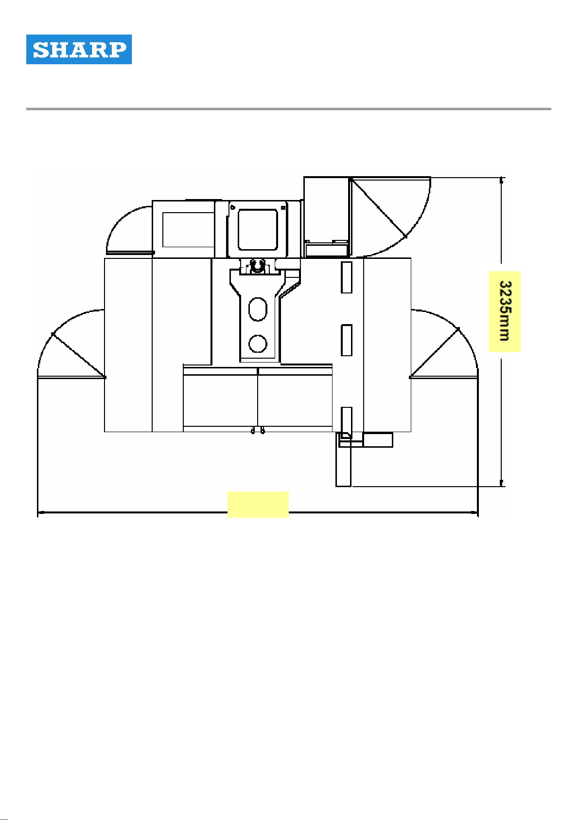
4600
Figure 1.2 TOP VIEW OF MACHINE
24
Page 25
PRECISION MACHINERY TOOLS VER.2 Operator’ s Manual
Chapter 2
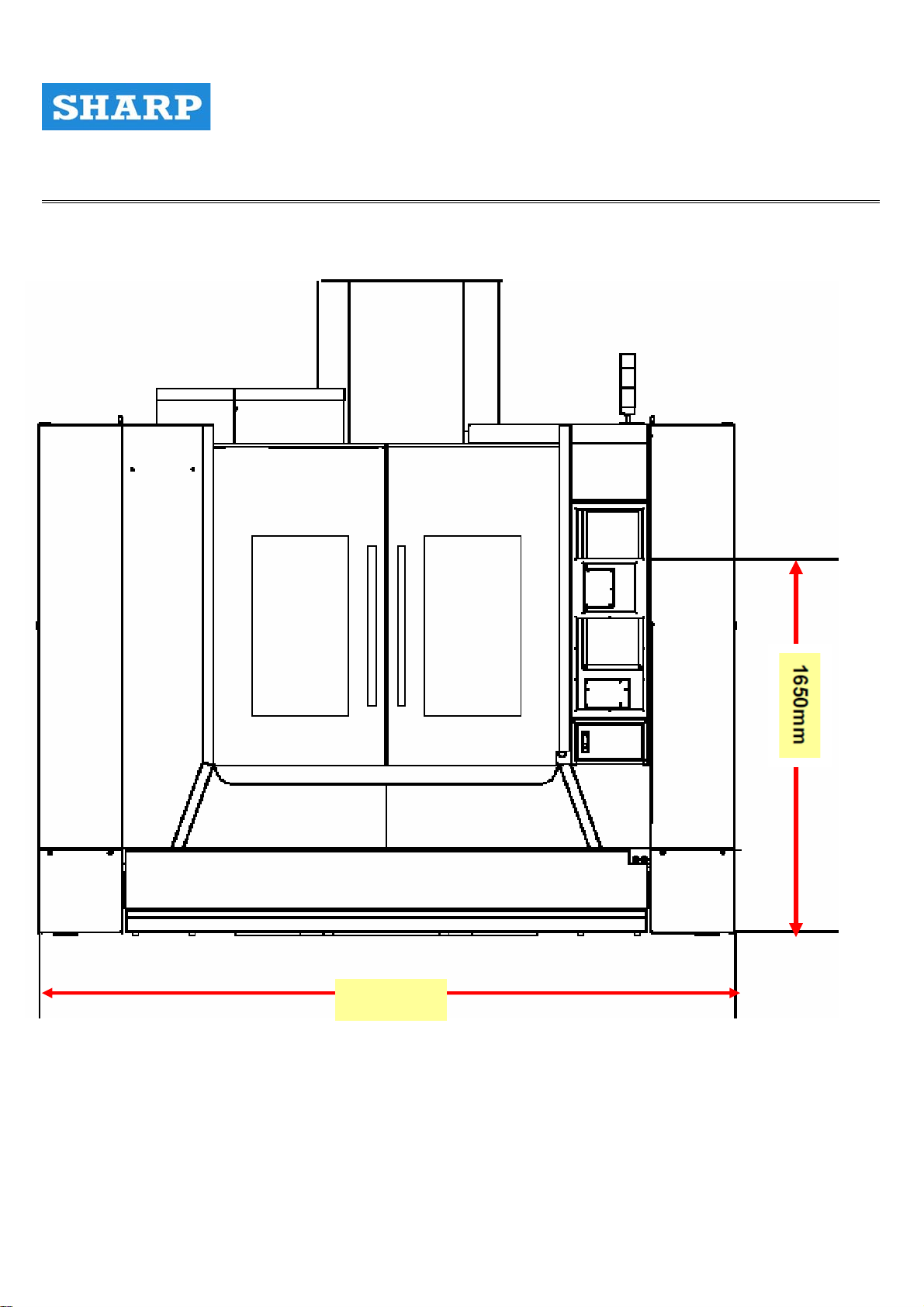
3200mm
Figure 1.3 FRONT VIEW OF MACHINE
25
Page 26
PRECISION MACHINERY TOOLS VER.2 Operator’ s Manual
Chapter 2
Figure 1.4 OPERATOR POSITION VIEW OF MACHINE
26
Page 27
PRECISION MACHINERY TOOLS VER.2 Operator’ s Manual
Chapter 2
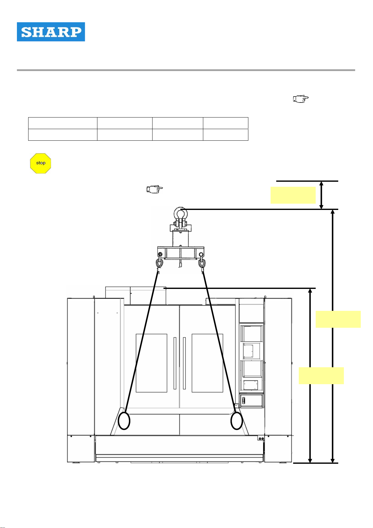
2. Preparation Of Transport Route
Prepare the machine transport route referring to the machine size at shipment ( Table 2.1 )
Item Height Width Depth
Machine Body 3100mm 3200mm 2825mm
When lifting the machine body using a crane the
total height requirement necessary to Provide
adequate lifting space is 500mm plus the height
of the lifting equipment . ( Figure 2.1 )
500mm
4250mm
2750mm
Figure 2.1 MACHINE BODY AT SHIPMENT
27
Page 28

PRECISION MACHINERY TOOLS VER.2 Operator’ s Manual
Chapter 2
3. Preparation Of Transportation Equipment
Prior to transportation of the machine, prepare equipment capable of supporting the
size and standing weight of the machine such as a crane, fork lift truck .
Table 3.1 MACHINE WEIGHT AT SHIPMENT
Item Weight ( including lifting equipment )
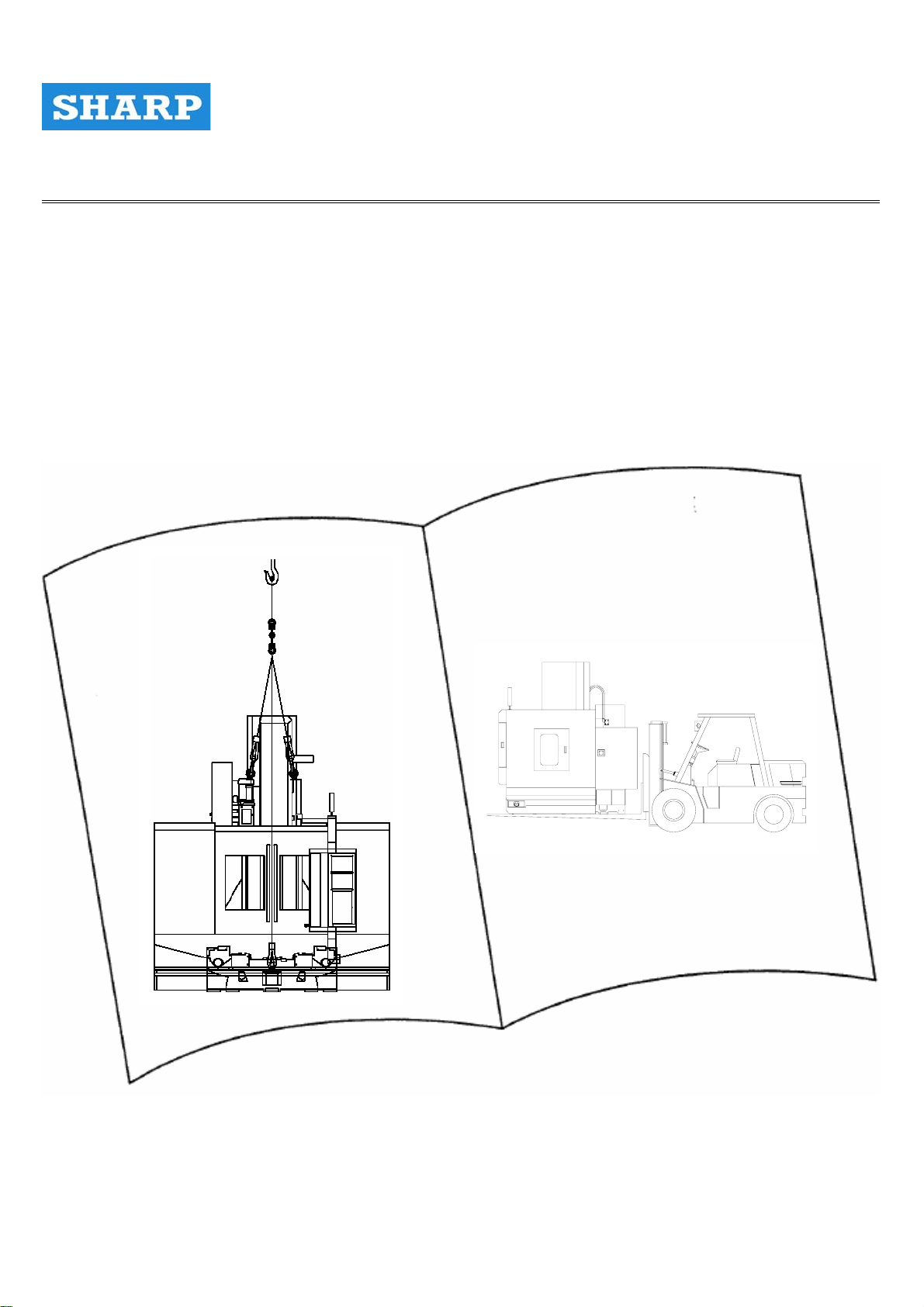
Machine body Approx. 8000Kg
Handling Unpackaged Machine
Handle the Unpackaged Machine by a Forklift
1. The unpackaged machine approximately weighs 7.5 tons. The forklift used for handling the
machine should have a safe load capacity greater than 9 tons so as to avoid accidents.
2. Check if there is any person or obstacle in the way while moving the machine.
Please evacuate people and remove obstacles before moving so as to avoid collision and
ensure the safety of personnel and machinery.
3. Adjust forks of a forklift to a proper position before moving. Pay attention to the barycenter
of the machine. Place it at the loading center of a forklift so as to avoid losing balance and
causing accidents.
4. When the machine is lifted by the forks, pay attention to the height the forks go. If the
barycenter is at a higher position, it may swing and lose balance and then cause accidents.
5. If the sight is hindered while moving the machine, please back the vehicle. Meanwhile, ask
someone to help give directions to ensure safety. Drive the forklift as slowly as possible
Figure 3.1 Handle the Unpackaged Machine by a Forklift
28
Page 29

PRECISION MACHINERY TOOLS VER.2 Operator’ s Manual
Chapter 2
4. SET-UP CONDITIONS
Table 4.1 SET-UP CONDITIONS
Set-Up Location And Environmental Conditions
Ambient Temperature:10 to 40 degrees
(optimum 26±1 degree )
Relative Humidity:35 to 70% ( no condensation )
Temperature Fluctuation:less than 1 degree / 1 hr
Well-illuminated
Free from direct sunlight
Dust-free
Available space for storing raw materials, finished workpieces and tools.
Available space for maintenance work .
Adequate space around machine to open doors completely
Required electrical power sources
A level foundation strong enough to support the weight of the machine
Appropriate distance from factory air ducting / inlets ( air flow )
29
Page 30

PRECISION MACHINERY TOOLS VER.2 Operator’ s Manual
Chapter 2
5. AIR / POWER SOURCE
Table 5.1 AIR / POWER SOURCE ( 1 )
Item Specifications
Electrical Source
Maximum Power Consumption 20 KVA ( Standard ) 35 KVA ( Including Options )
Total Power Requirements
Air Source
Air Dryer Should be ordered or unless provided by customer
Air Filtration Unit 5μm + 0.3μm + Moisture Remover
AC200/220V ± 10% & 50/60HZ ± 2%
Actual:
20 * 0.7 = 14 KVA ( Standard )
35 * 0.7 = 25 KVA ( Including Options )
0.5 to 0.8 MPa
660L / min ( ANR) without scale with air blow
Dew point temperature: -20 degrees or less
•Clean air is to be provided:Equivalent to ISO 1.5.1
standard as specified by ISO 8573-1
•Max. particle diameter:0.0001mm or less
•Dew point at max pressure:Below 7 degrees
•Max oil concentration :0.01 mg/m³ or less
30
Page 31

PRECISION MACHINERY TOOLS VER.2 Operator’ s Manual
Table 5.2 AIR / POWER SOURCE ( 2 )
Power Source Breaker Rated Current ( A) Cable Size ( Ex )
Chapter 2
Up to AC240V 225
IV:600V PVC insulated wire
10mm²IV
Figure 5.1 Electrical Power Source Connection
AIR SOURCE
Figure 5.2 Air Source Connection
31
Page 32

PRECISION MACHINERY TOOLS VER.2 Operator’ s Manual
Chapter 2
6. RECOMMENDED FOUNDATIONS
Table 6.1 Recommended foundation
Item Specification
Ground Resistance
Foundation Construction Shown in Figure 6.1
5000Kg/ m² or more
Front
Rrae
Figure 6.1 Foundation Drawing
32
Page 33

PRECISION MACHINERY TOOLS VER.2 Operator’ s Manual
Chapter 2
Figure 6.2 Foundation Drawing
Figure 6.3 Foundation Drawing
33
Page 34

PRECISION MACHINERY TOOLS VER.2 Operator’ s Manual
Chapter 2
NOTES:
1. Foundation preparation are generally not required if the floor thinkness is 500mm or more of
reinforced concrete . However, when additional machinery is in use surrounding the machine,
foundation preparations are required.
2. The following data is to be used as a reference. Concrete required is FC180 standard and
above.
→ For rubble, use medium or large size crushed stones.
→ Section C ensures isolation from surrounding vibration. Use small crushed stone.
→ leveling concrete thickness:200mm
The foundation drawings on previous pages show only recommended values. Foundation
stop
requirements vary according to ground conditions. Prior to performing
foundation preparations, consult a civil engineer or building contractor.
34
Page 35

PRECISION MACHINERY TOOLS VER.2 Operator’ s Manual
Chapter 3
Chapter 3 OPERATION
35
Page 36

PRECISION MACHINERY TOOLS VER.2 Operator’ s Manual
Chapter 3
BEFORE STARING OPERATION
Preparation staring
For machine operation
OPERATION FLOWCHART
POWER ON
PRE-OPERATION
CHECKS
MACHINING
PREPARATION
DATA REGISTRATION/
EDITING
Chart 1 SAFETY
1. MAIN OPERATION PANEL
2. M - CODE
3. SETTING/CHANGING MACHINE PARAMETERS
4. OPENING/CLOSEING DOORS
5. TURNING ON/OFF POWER SUPPLY
CHART 5 PERIODIC MAINTENANCE LIST ( 1/3 )
PRE-OPERATION MAINTENANCE
6. DATA REGISTRATION/
EDITING
1. MAIN OPERSTION
NC PROGRAM
PANEL
2. M-CODE
TOOL NUMBER
TOOL OFFSET VALUE
WORKPIECE OFFSET VALUE
WORKPIECE
MACHINING MACHINING
PREPARATION
TOOL PREPARATION
36
7. WORKING SETTING
→ 4. OPENING/CLOSING DOORS
8. TOOL PREPARATIONS
→ 11. TOOL CHANGE
9. TOOL CHANGE
10. CUTTING FLUID SUPPLY
11. CHIP DISPOSAL
12. AUTOMATIC OPERATION
Page 37

PRECISION MACHINERY TOOLS VER.2 Operator’ s Manual
Chapter 3
1. MAIN OPERATION PANEL
The main operation panel is used to perform the following operations;
‧Manual / Automatic operation
‧Turning functions on/ off and changing operating modes
‧Registering and editing NC programs
‧Inputting tool offset values and work coordinate system settings
‧Changing parameters
‧Display alarm screens and maintenance operations
1.1 MAIN OPERATION PANEL FUNCTIONS
Reference point /
Status / Alarm
Spindle tool number
display
Axis selection function
OT Release
Axis Rapid travel
function
Spindle manual
operation
37
Page 38

PRECISION MACHINERY TOOLS VER.2 Operator’ s Manual
Chapter 3
M03 Spindle ON
CLOCKWISE
M04 SPINDLE
ON COUNTER-
CLOCKWISE
Spindle STOP
38
Page 39

PRECISION MACHINERY TOOLS VER.2 Operator’ s Manual
Chapter 3
PROGRAMMING FUNCTION
BUTTON
CUTTING FUNCTION
BUTTON
OPTION FUNCTION BUTTON
39
Page 40

PRECISION MACHINERY TOOLS VER.2 Operator’ s Manual
Chapter 2
PROGRAM RESTART:The case of cutting tool breakage, or after the
holidays , this function enables restart the program .
1) Press this button on, display the program to be restarted inputting
either the sequence number or the block number.
Air blast button:
Press this button to start air blast, press it again to stop it
40
Page 41

PRECISION MACHINERY TOOLS VER.2 Operator’ s Manual
Chapter 3
.
.
41
Page 42

PRECISION MACHINERY TOOLS VER.2 Operator’ s Manual
Chapter 3
42
Page 43

PRECISION MACHINERY TOOLS VER.2 Operator’ s Manual
Chapter 3
43
Page 44

PRECISION MACHINERY TOOLS VER.2 Operator’ s Manual
Chapter 3
44
Page 45

PRECISION MACHINERY TOOLS VER.2 Operator’ s Manual
Chapter 3
PROGRAMMING FUNCTION
BUTTON DESCRIPTION
45
Page 46

p
PRECISION MACHINERY TOOLS VER.2 Operator’ s Manual
Chapter 3
4TH & 5TH-axis On/off extraction:
a. When you need to use 4TH & 5TH-axis. (Servo ready)
Ignore 4TH & 5TH-axis button is off. (Light is off)
b. When you want to off the 4TH & 5TH-axis. (Servo not ready)
Ignore 4TH & 5TH-axis button is on. (Light is on)
c. When you push this button, you need to restart the main
ower.
L/R button for tool magazine:
This function is not available in this machine.
46
Page 47

PRECISION MACHINERY TOOLS VER.2 Operator’ s Manual
Chapter 3
TURNING ON/OFF POWER SUPPLY
POWER ON:
1) Turning on the main power switch
2) Press the [ CONTROL POWER ON ] button
POWER OFF:
1) Press the [ CONTROL POWER OFF ] button
2) Turning off the main power switch
3) Emergency stop should be pressed before pressing this button).
47
Page 48

PRECISION MACHINERY TOOLS VER.2 Operator’ s Manual
Chapter 3
ROTATION SELECT
SWITCH DESCRIPTION
48
Page 49

PRECISION MACHINERY TOOLS VER.2 Operator’ s Manual
Chapter 3
DESCRIPTION OF MODE SELECT SWITCH
49
Page 50

PRECISION MACHINERY TOOLS VER.2 Operator’ s Manual
Chapter 3
50
Page 51

PRECISION MACHINERY TOOLS VER.2 Operator’ s Manual
Chapter 3
51
Page 52

PRECISION MACHINERY TOOLS VER.2 Operator’ s Manual
Chapter 3
PROGRAM START /
FEED HOLD DESCRIPTION
52
Page 53

PRECISION MACHINERY TOOLS VER.2 Operator’ s Manual
Chapter 3
Ready and program protection key button
After press “power control on” button, press this button to make
machine ready to be operated.
HANDWHEEL DESCRIPTION
1. HANDWHEEL
FUNCTION AS ON PANEL
2. AXIS SELECT SWITCH
TO SELECET AXIS IN
MANUAL MODE
3. HANDWHEEL SCALE
MULTIPLE
53
Page 54

PRECISION MACHINERY TOOLS VER.2 Operator’ s Manual
Chapter 3
SIGNAL LIGHT DESCRIPTION
STATUS LAMPS DESCRIPTION
54
Page 55

PRECISION MACHINERY TOOLS VER.2 Operator’ s Manual
Chapter 3
`
55
Page 56

PRECISION MACHINERY TOOLS VER.2 Operator’ s Manual
Chapter 3
LAMP ATC ALARM
WHEN ATC NOT INPOSITION, THIS LAMP LIGHTS
Manual tool holder clamp/unclamp button
56
Page 57

PRECISION MACHINERY TOOLS VER.2 Operator’ s Manual
Chapter 3
1.2 LCD CONTROLPANEL FUNCTION
CF CARD
INTERFACE
HELP KEY
MENU BACK
SOFT KEY
RESET KEY ADDRESS/NUMERIC KEY
FUNCTION SOFT
KEY
CHANGE MENU
SOFT KEY
EDIT KEYS
CANEL KEY
SHIFT KEY
PAGE
UP/DOWN
KEYS
INPUT KEY
PROGRAM
SINGLE BLOCK
END KEY
FUNCTION KEYSCURSOR KEYS
57
Page 58

PRECISION MACHINERY TOOLS VER.2 Operator’ s Manual
Chapter 3
58
Page 59

PRECISION MACHINERY TOOLS VER.2 Operator’ s Manual
Chapter 3
59
Page 60

PRECISION MACHINERY TOOLS VER.2 Operator’ s Manual
Chapter 3
60
Page 61

PRECISION MACHINERY TOOLS VER.2 Operator’ s Manual
Chapter 3
1.3 DISPLAYING NC SCREEN
61
Page 62

PRECISION MACHINERY TOOLS VER.2 Operator’ s Manual
Chapter 3
62
Page 63

PRECISION MACHINERY TOOLS VER.2 Operator’ s Manual
Chapter 3
MDI KEYBORD FUNCTION
63
Page 64

PRECISION MACHINERY TOOLS VER.2 Operator’ s Manual
Chapter 3
2. M_CODE LIST
2.1 M_CODE LIST SELECT
SPINDLE
`
M Code Define
M03 Spindle CW
M04 Spindle CCW
M05 Spindle stop
M19 Spindle orientation
M29 Rigid tapping
PROGRAMMING
M Code Define M Code Define
M00 Program Stop M24 A axis mirror image
M01 Optional program stop M30 Program End
M02 Program end M46 Override cancel
M21 X axis mirror image on
M22 Y axis mirror image on
M23 Mirror image off
M98
M99
64
Call sub-program
Program re-start / Return to main program
Page 65

PRECISION MACHINERY TOOLS VER.2 Operator’ s Manual
Chapter 3
COOLANT
M Code Define M Code Define
M07 Cutting air blow on M15 High pressure coolant chip remove on
M08 Coolant pump on M16 High pressure coolant chip remove off
M09 Coolant pump off M48 CTS on
M10 Cutting air blow off M50 Chip conveyor CW
M13 Spindle CW and coolant on M51 Chip conveyor stop
M14 Spindle CCW and coolant
on
TOOL CHANGE
M Code Define M Code Define
M06 Auto tool change M71 Tool pot down
M41
M42
M52 Magazine extend M76 Arm return to home position
M53 Magazine return M77 Tool pot up
M66
Magazine extend for M6
M72 Arm move to catch tools
macro
Magazine tool command
M74 Arm move to exchange tools
search for M6 macro
Auto tool change start for
M90 Magazine search tool number command
M6
M70
Automatic tool data table
M95 Arm trouble shooting
re-building
65
Page 66

PRECISION MACHINERY TOOLS VER.2 Operator’ s Manual
Chapter 3
3. SETTING / CHANGING MAVHINE PARAMETER
3.1 DISPLAYING PARAMETERS
66
Page 67

PRECISION MACHINERY TOOLS VER.2 Operator’ s Manual
Chapter 3
3.2 SETTING PARAMTERS FROM MDI
67
Page 68

PRECISION MACHINERY TOOLS VER.2 Operator’ s Manual
Chapter 3
68
Page 69

PRECISION MACHINERY TOOLS VER.2 Operator’ s Manual
Chapter 3
69
Page 70

PRECISION MACHINERY TOOLS VER.2 Operator’ s Manual
Chapter 3
4. Opening / Closing doors
4.1 Opening / Closing Splashguard Door
Operation Door Safety Guard
Emergency Stop Button
Figure 4.1 position of splashguard door and operation
70
Page 71

PRECISION MACHINERY TOOLS VER.2 Operator’ s Manual
Chapter 3
71
Page 72

PRECISION MACHINERY TOOLS VER.2 Operator’ s Manual
Chapter 3
72
Page 73

PRECISION MACHINERY TOOLS VER.2 Operator’ s Manual
Chapter 3
5. TURNING ON / OFF POWER SUPPLY
MAIN POWER SWITCH
POWER ON BUTTON
Figure 5.1 LOCATION OF POWER SUPPLY SWITCH AND BUTTON
POWER OFF BUTTON
73
Page 74

PRECISION MACHINERY TOOLS VER.2 Operator’ s Manual
Chapter 3
74
Page 75

PRECISION MACHINERY TOOLS VER.2 Operator’ s Manual
Chapter 3
75
Page 76

PRECISION MACHINERY TOOLS VER.2 Operator’ s Manual
Chapter 3
6. DATA REGISTRATION / EDITING
6.1 NC Program Registration ( 3 Methods )
INPUT THE NC DATA USING A MERORY CARD
Figure 6.1 POSITION OF RS232C POART / MEMORY CARD INTERFACE / KEYBOARD
INPUT THE NC DATA USING A KEYBOARD
INPUT THE NC DATA VIA RS232C PORT
6.2 Tool Offset Registration
76
Page 77

y
PRECISION MACHINERY TOOLS VER.2 Operator’ s Manual
Chapter 3
Procedure
Tool Compensation
Memor
A
77
Page 78

y
PRECISION MACHINERY TOOLS VER.2 Operator’ s Manual
Chapter 3
Tool Compensation
Memor
C
Explain
78
Page 79

PRECISION MACHINERY TOOLS VER.2 Operator’ s Manual
Chapter 3
6.3 Number Of Tool Offset Value
79
Page 80

PRECISION MACHINERY TOOLS VER.2 Operator’ s Manual
Chapter 3
6.4 Registration Of Workpiece Offset Value
80
Page 81

PRECISION MACHINERY TOOLS VER.2 Operator’ s Manual
Chapter 3
81
Page 82

PRECISION MACHINERY TOOLS VER.2 Operator’ s Manual
Chapter 3
82
Page 83

PRECISION MACHINERY TOOLS VER.2 Operator’ s Manual
Chapter 3
83
Page 84

PRECISION MACHINERY TOOLS VER.2 Operator’ s Manual
Chapter 3
7. WORKPIECE SETTING
z Workpiece attachment and detachment
1. WORKPIECE ATTACHMENT AND DETACHMENT
z Workpiece restrictions
1. WORKPIECE ATTACHMENT AND DETACHMENT 1-1
2. WORKPIECE RESTRICTIONS
WORKPIECE LOADING SPACE
Figure 1-1 POSITION OF WORKPIECE ATTACHMENT AND DETACHMENT
84
Page 85

PRECISION MACHINERY TOOLS VER.2 Operator’ s Manual
Chapter 3
2. WORKPIECE RESTRICTIONS
1) Load Capacity:1000Kgs
2) Table size:Shown in Figure 8.2
`
650 mm 650 mm
325 mm
Figure 8.2 WORKPIECE RESTRICTIONS
85
Page 86

PRECISION MACHINERY TOOLS VER.2 Operator’ s Manual
Chapter 3
8. TOOL PREPARATIONS
8.1 Tool Attachment and Detachment ( Figure 1-1 )
1) Make sure the spindle is at a complete stop and ready for a tool change .
2) Firmly insert the tool in the spindle .
3) Press the tool clamp / unclamp button ( Figure 1-2 ) on the front of the head .
4) Release the tool clamp / unclamp button .
5) Maker sure the tool is completely and correctly inserted before releasing the
tool .
Figure 1-1 Tool Attachment and Detachment Figure 1-2 Tool clamp / unclamp button
86
Page 87

PRECISION MACHINERY TOOLS VER.2 Operator’ s Manual
Chapter 3
8.2 Tool storage limitations
Items Maximum Value
Storage Capacities 24 Tools
Maximum Tool Diameter Allowed for
Continuous Mounting
Maximum T ool Diameter with Adjacent
Post Empty
Maximum Tool Length 300 (11.8) mm( inch)
Maximum Tool W eight
8.3 Tool And Retention Stud combinations
BT SHANK
125(4.9)
mm( inch)
200( 7.8)
mm( inch)
6 ( 13.2) ㎏(lb)
87
Page 88

PRECISION MACHINERY TOOLS VER.2 Operator’ s Manual
Chapter 3
88
Page 89

PRECISION MACHINERY TOOLS VER.2 Operator’ s Manual
Chapter 3
CAT 40 STUD
89
Page 90

PRECISION MACHINERY TOOLS VER.2 Operator’ s Manual
Chapter 3
DIN 40 STUD
90
Page 91

PRECISION MACHINERY TOOLS VER.2 Operator’ s Manual
Chapter 3
9. Tool CHANGES
91
Page 92

PRECISION MACHINERY TOOLS VER.2 Operator’ s Manual
Chapter 3
10. CUTTING FLUID SUPPLY
10.1 CUTTING FLUID SUPPLY UNIT FOR SPINDLE
Spindle Side Coolant
( Two Pipe For water )
( One Pipe For Air )
Base Coolant
Terrace Cleaning Coolant
10.2 CUTTING FLUID SUPPLY UNIT FOR BASE
92
Page 93

PRECISION MACHINERY TOOLS VER.2 Operator’ s Manual
Chapter 3
Table 10.1 CUTTING FLUID SUPPLY UNIT OPERATION CHART
Setting Method
Unit
Spindle Side Coolant
Base Coolant
( Terrace Cleaning Coolant )
Through- Spindle Coolant
Main
Operation Panel
M-Code
M08 ( Start ) M09 ( Stop )
M13
( SPINDLE CW / COOLANT PUMP ON )
M14
( SPINDLE CW / COOLANT PUMP OFF )
M15 ( Start ) M16 ( Stop )
M13
( SPINDLE CW / COOLANT PUMP ON )
M14
( SPINDLE CW / COOLANT PUMP OFF )
M48 ( Start ) M09 ( Stop )
11. CHIP DISPOSAL
Lift- Up Conveyor
Coolant Tank
Figure 11.1 LIFT- UP CONVEYOR
93
Page 94

PRECISION MACHINERY TOOLS VER.2 Operator’ s Manual
Chapter 3
Oil Skimer
Figure 11.2 OIL SKIMER & OIL LEVEL INDICAOR
Oil Level Indicator
11.1 OPERATION OF LIFT-UP CONVEYOR
A. Automatic Operation
Conveyor forward operation is performed in connection with the cutting
fluid discharge start command .
B. Manual Operation
1 ) Forward Manual Operation
a. Press the “CW” button as below,
the conveyor rotation in forward
direction .
b. Press the “CW” button again,
the conveyor be stop .
2 ) Reverse Manual Operation
a. Keep pressing the “CCW “ button
as below, the conveyor rotation in
reverse direction .
b. Release the “CCW “button
, the conveyor be stop .
94
Page 95

PRECISION MACHINERY TOOLS VER.2 Operator’ s Manual
Chapter 3
12. AUTOMATIC OPERATION
1. Program Edit Procedure
95
Page 96

PRECISION MACHINERY TOOLS VER.2 Operator’ s Manual
Chapter 3
2. Program Configuration
96
Page 97

PRECISION MACHINERY TOOLS VER.2 Operator’ s Manual
Chapter 3
97
Page 98

PRECISION MACHINERY TOOLS VER.2 Operator’ s Manual
Chapter 3
3. Subprogram Call
98
Page 99

PRECISION MACHINERY TOOLS VER.2 Operator’ s Manual
Chapter 3
99
Page 100
PRECISION MACHINERY TOOLS VER.2 Operator’ s Manual
Chapter 3
4. Major Functions And Address
100
 Loading...