

Page 1
TopPage
DESTINATION T
Refrigerant; HFC-134a
SJ-D20N/D24N/D28N/D29N-SLG
SERVICE MANUAL
No. S9633SE26ATUTT
Refrigerator-freezer
MODELS
SJ-D20N-SLG
SJ-D24N-SLG
SJ-D28N-SLG
SJ-D29N-SLG
Refer to "HFC-134a COOLING UNIT" Service Manual for handling this refrigerant.
CONTENTS
CHAPTER 1. SPECIFICATION
CHAPTER 2. DESIGNATION OFVARIOUS PARTS
[1] EXTERNAL DESCRIPTION .......................... 2-1
[2] CONSTRUCTIONS........................................ 2-2
CHAPTER 3. DIMENTIONS
[1] OUTER DIMENTIONS AND
CLEARANCE ................................................. 3-1
[2] INNER DIMENTIONS .................................... 3-3
CHAPTER 4. LIST OF ELECTORICAL PARTS
CHAPTER 5. WIRING DIAGRAM
[1] WIRING DIAGRAM........................................ 5-1
[2] ELECTRIC ACCESSORIES LAYOUT ........... 5-2
CHAPTER 6. FAILURE DIAGNOSIS
[1] OUTLINE OF CONTROL............................... 6-1
[2] CHECK MODE OF DEFROST HEATER
(Forced Defrosting) ........................................ 6-1
[3] RE-SETTING OF MICROCOMPUTER AT
POWER FAILURE ......................................... 6-2
[4] DIAGNOSIS METHOD OF FAILURE............ 6-2
[5] CONVERSION TABLE.................................. 6-3
[6] CIRCUIT DIAGRAM OF MAIN PWB ............. 6-4
CHAPTER 7. FUNCTIONS
[1] ADJUSTABLE TEMPERATURE
CONTROL..................................................... 7-1
CHAPTER 8. ASSEMBLING PROCEDURES OF
MAIN PARTS AND CAUTIONS
[1] F-LOUVER ASS'Y ......................................... 8-1
[2] R CONTROL COV. ASS'Y ............................ 8-4
[3] HOW TO REPLACE THE LAMP................... 8-6
[4] DEFROST HEATER ...................................... 8-7
CHAPTER 9. COOLING UNIT
[1] COOLING UNIT ............................................ 9-1
[2] LOCATION .................................................... 9-2
Parts Guide
This document has been published to be used for
after sales service only.
The contents are subject to change without notice.
Page 2
SJD24NSLG
1 – 1
SJD24NSLG
Service Manual
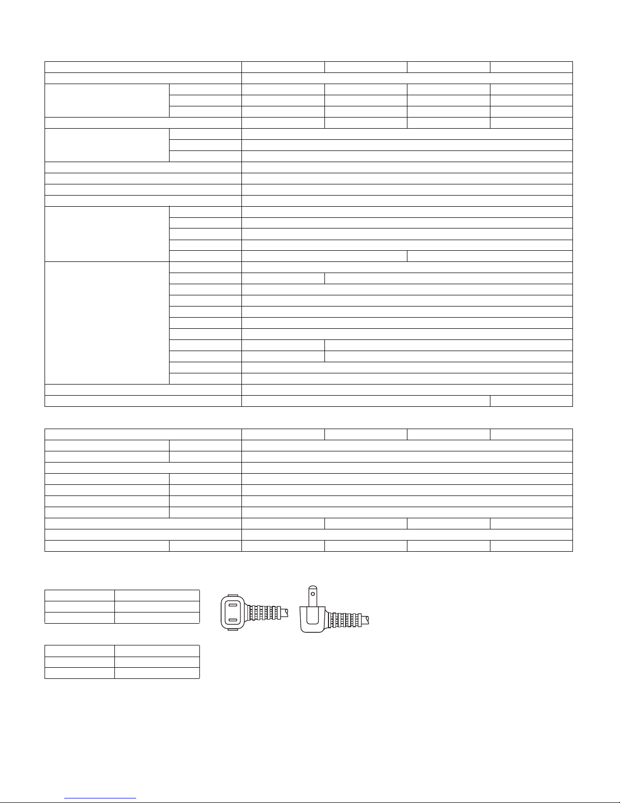
CHAPTER 1. SPECIFICATION
Items SJ-D20N SJ-D24N SJ-D28N SJ-D29N
Type 2-Door
Outer dimensions Height 1253mm(49.3") 1389mm(54.7") 1491mm(58.7") 1627mm(64.1")
Width 545mm(21.5") 545mm(21.5") 545mm(21.5") 545mm(21.5")
Depth 620mm(24.4") 620mm(24.4") 620mm(24.4") 620mm(24.4")
Rated storage volume (Rated volume) 184liter(6.5cu.ft) 212liter(7.5cu.ft) 227liter(8.0cu.ft)
Defrosting System Heater system
Start Automatic
Finish Automatic
Temperature control Automatic (Adjustable)
No-frost freezer Yes
Interior lamp 1
Evaporating pan 1
Freezer Compartment F-shelf 1
F-shelf S 1
Ice cube maker Twin ice cube maker
Ice storage box 1
Door pocket 1 2
Refrigerator Compartment Fresh case 1
R shelf ass'y — 1
R shelf S ass'y 1
R shelf L ass'y 1
V shelf 1
Vegetable case 1
Egg pocket 1
Small pocket — 1
Carry case ass'y — 1
Bottle pocket 1
Door pocket 1
Deodorizing unit 1 (Honeycomb type)
Stand Yes No
RATING
Items SJ-D20N SJ-D24N SJ-D28N SJ-D29N
Rated voltage (V) 220
Rated frequency (Hz) 50
Climate class T
Power input (W) 100
Current input (A) 0.53
Defrosting current (A) 0.58
Defrosting power (W) 128
Refrigerant (Charging quantity) [Non-flammable] HFC-134a(90g) HFC-134a(90g) HFC-134a(95g) HFC-134a(95g)
Insulation blowing gas [Flammable] Cyclo pentane (HC)
Net Weight (kg) 41 43 46 48
PLUG TYPE
Plug cord 2 pin
Plug type A-1
Destination mark T
COLOR
Items -SLG
Outside color Silver
Inside color White
Page 3
SJD24NSLG
2 – 1
SJD24NSLG
Service Manual
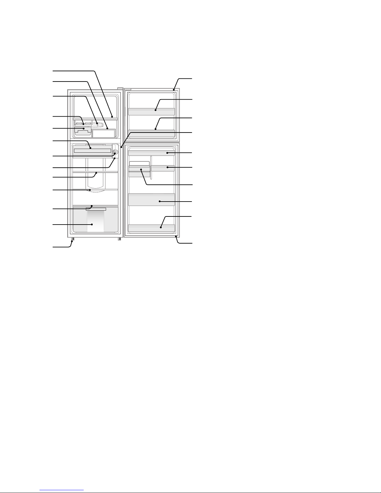
CHAPTER 2. DESIGNATION OFVARIOUS PARTS
[1] EXTERNAL DESCRIPTION
The names in parenthesis "[ ]" are the denominations used in the REPLACEMENT PARTS LIST.
1
2
3
4
5
6
7
8
9
10
11
12
13
14
15
15
16
17
18
19
20
15
14
1. Freezer shelf [F-shelf]
2. Freezer shelf (movable) [F-shelf s]
3. Freezer temp.control knob
4. Ice cube maker
5. Ice cube box [Ice storage box]
6. Fresh room
7. Refrigerator temp.control knob
8. Light [Lamp]
9. Refrigerator shelf [R-shelf ass'y]
(Except for SJ-D20N)
10.
Half shelf(1 pair) [R-shelf s ass'y,R-shelf l ass'y]
11. Vegetable shelf [V-shelf]
12. Vegetable crisper [Vegetable case]
13. Adjustable foot [Adjustable leg]
14. Magnetic door seal [Door packing]
15. Door pocket
(SJ-D20N/SJ-D24N ; 2 pockets,
SJ-D28N/SJ-D29N ; 3 pockets)
16. Light switch
17. Egg pocket
18. Small pocket
(Except for SJ-D20N)
19. Cosmetic box
(Except for SJ-D20N)
20. Bottle pocket
Page 4

SJD24NSLG
2 – 2
[2] CONSTRUCTIONS
Fan motor
Def-thermistor
F-temp. control knob
R-temp. control knob
Evaporator
Defrost heater
Deodorizing unit
R-thermistor
PWB L ass'y
Running capacitor
Lamp
Compressor
Starting relay
Protector
Evaporating pan
Mark: Cold air flow
Fuse ass'y
Page 5
SJD24NSLG
3 – 1
SJD24NSLG
Service Manual
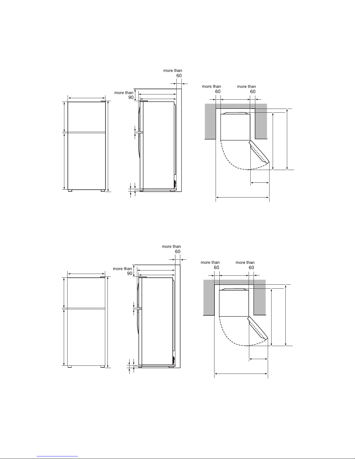
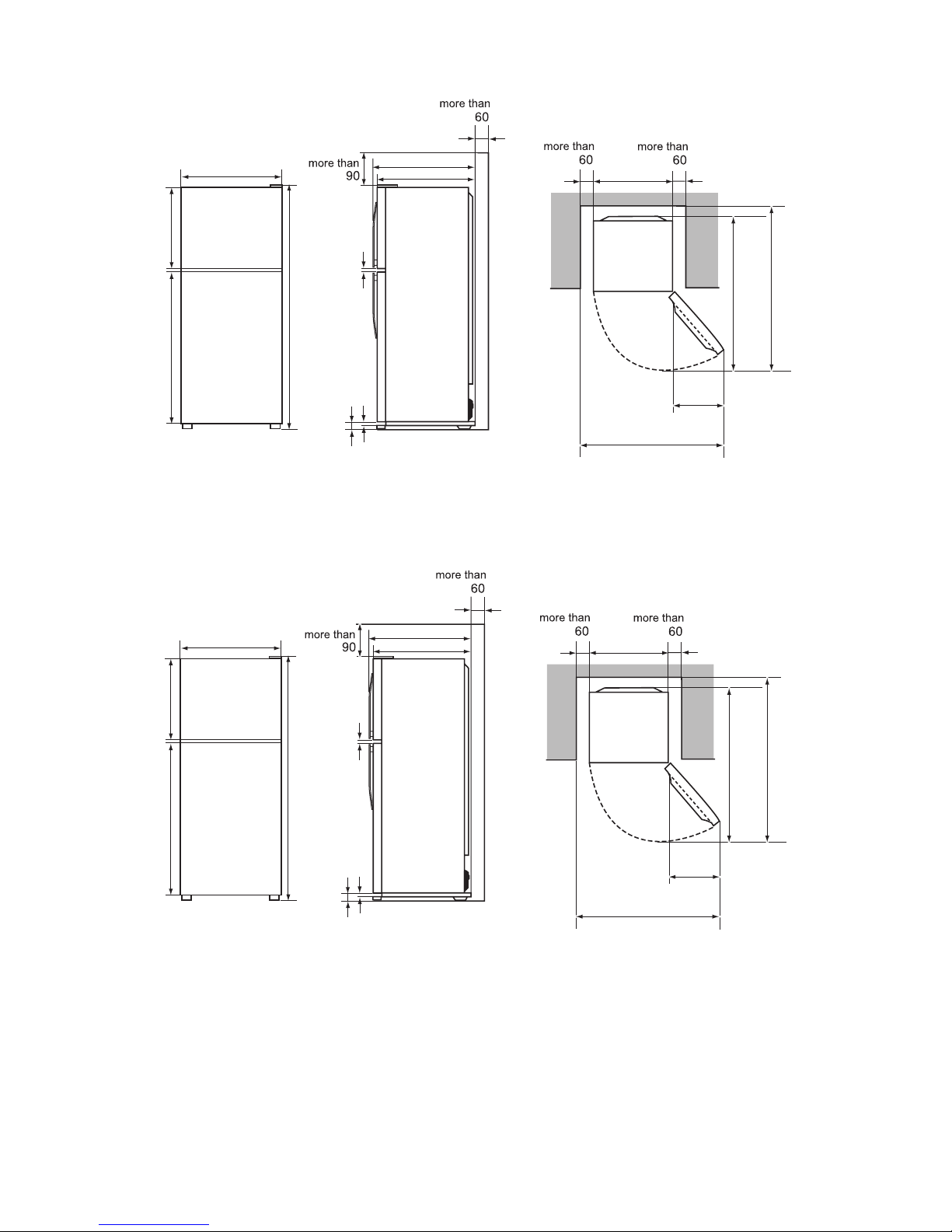
CHAPTER 3. DIMENTIONS
[1] OUTER DIMENTIONS AND CLEARANCE
1. SJ-D20N
2. SJ-D24N
(Unit:mm)
9
34
4
620
638.5
1095
545
1155
365
970
545
443.5
757.5
1253
(Unit:mm)
9
34
4
620
638.5
1095
545
115 5
365
970
545
443.5
893.5
1389
Page 6
SJD24NSLG
3 – 2
3. SJ-D28N
4. SJ-D29N
(Unit:mm)
9
34
4
620
638.5
1095
545
1155
365
970
545
515.5
923.5
1491
(Unit:mm)
9
34
4
620
638.5
1095
545
115 5
365
970
545
515.5
1059.5
1627
Page 7
SJD24NSLG
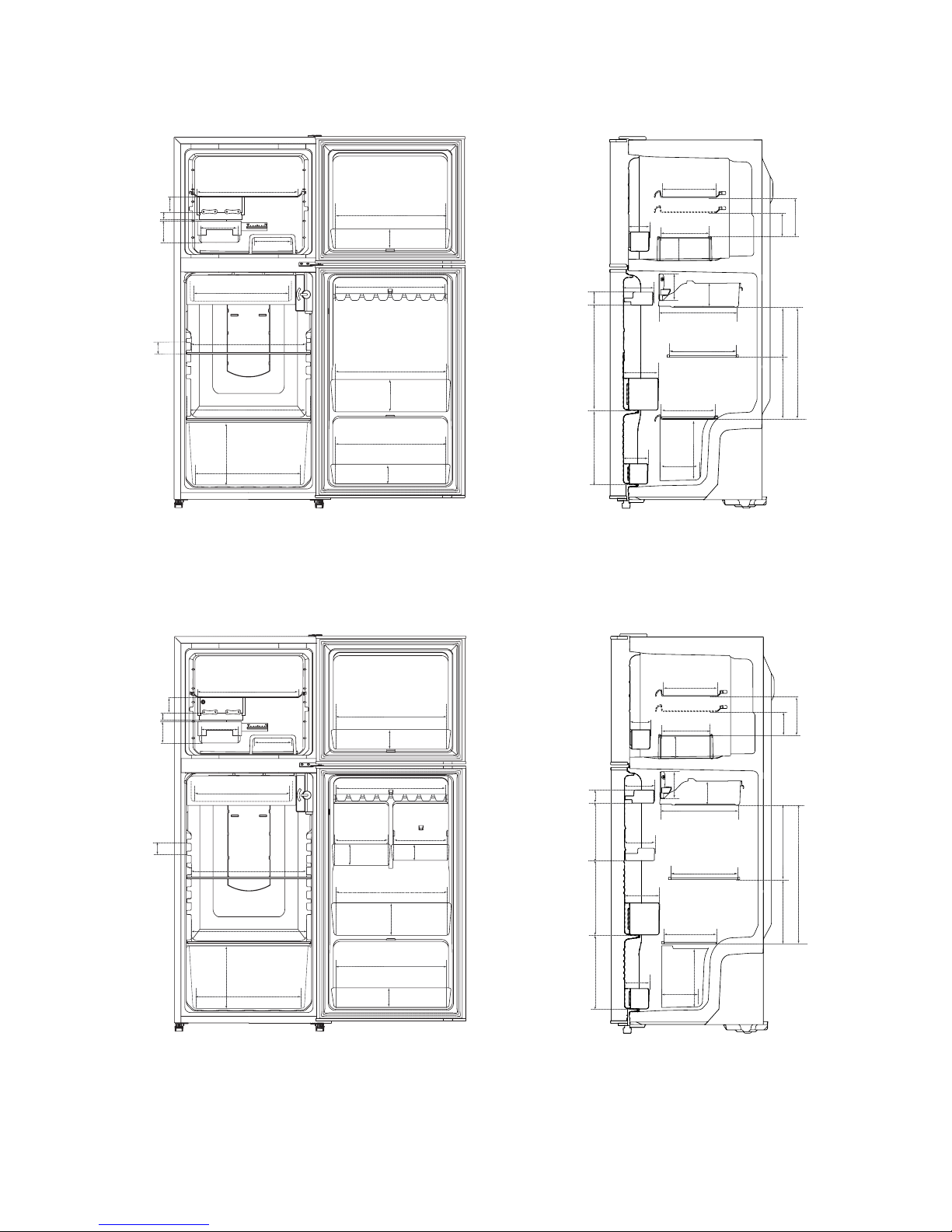
3 – 3
[2] INNER DIMENTIONS
1. SJ-D20N
2. SJ-D24N
380
390
253
321
45
146
149
300
67
107
67
196
55
43
391
38
33
138
140
417
417
363
208
371
366
366
137
208
126
76
103
250
143
107
66
180
75
120
80
211
292
340
(Unit:mm)
196
55
43
380
390
45
391
38
33
138
140
169
417
417
363
208
168
371
366
366
67
30
107
67
137
208
253
271
214
230197
434
126
76
103
250
143
107
66
180
75
120
80
91
211
292
50
340
(Unit:mm)
Page 8
SJD24NSLG
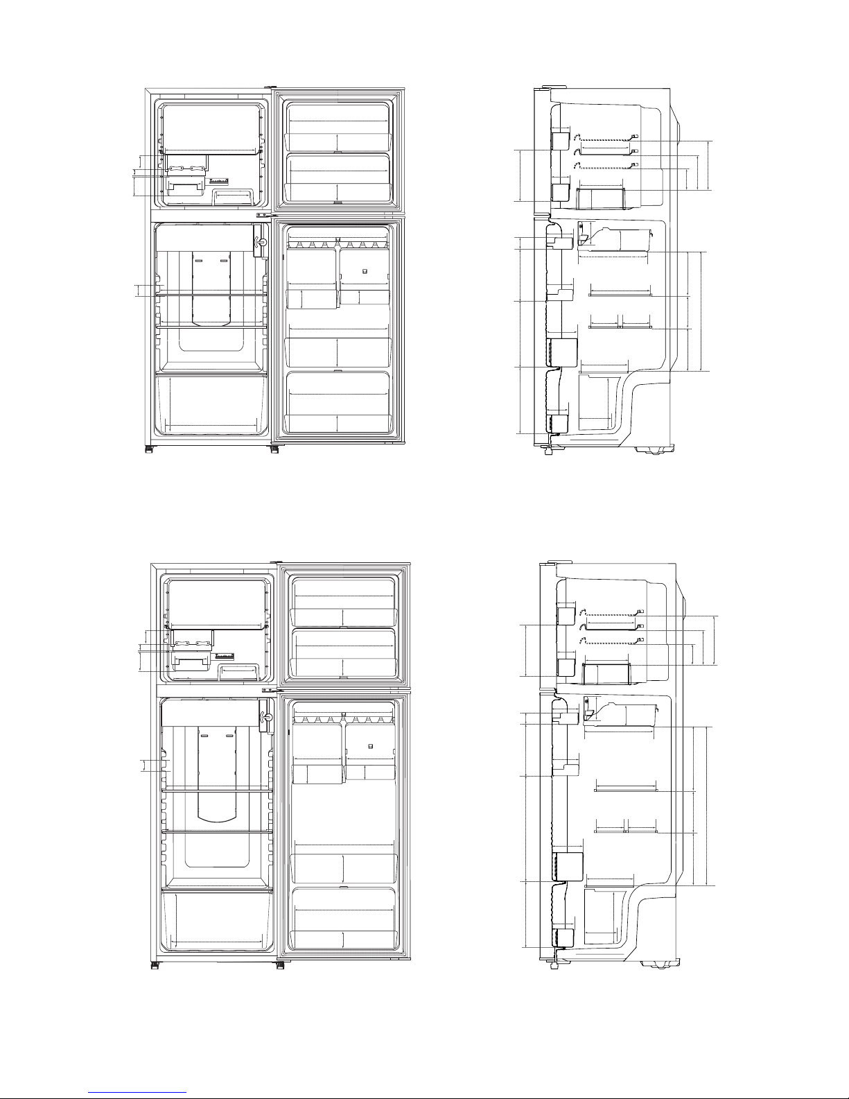
3 – 4
3. SJ-D28N
4. SJ-D29N
391
38
3355
43
138
140
390
169
417
417
417
363
208
137
208
253
271
214
45
103
250
143
107
66
66
202
176
126
76
464
144123184
196
180
75
120
80
91
168
50
30
10767
371
366
67
366
67
366
292
130 130
211
(Unit:mm)
391
38
3355
43
138
140
390
169
417
417
417
363
208
137
208
284 376
232168193
602
214
45
103
250
143
107
66
66
202
176
126
76
196
180
75
120
80
91
168
50
30
10767
371
366
67
366
67
366
292
130 130
211
(Unit:mm)
Page 9
SJD24NSLG
4 – 1
SJD24NSLG
Service Manual
CHAPTER 4. LIST OF ELECTORICAL PARTS
ITEMS
TYPE NAME
Thermo. fuse
Defrost heater
Lamp
Compressor
Starting Relay
Overload Relay(Protector)
Main PWB
(D20/D24/D28)
SF70E
FL1152-SZ
FPWB-A451CBKZ
220-240V 378
220-240V/50Hz
Working temp. : 70 C
140W at 230V
Open/ Close : 120 / 61 C
Cooling capacity : 136W (50Hz)
Main coil : 23.8
Aux. coil : 42.4
(at 75 C)
W
Common
Aux. coil
Main coil
240V 15W
Door switch SDKNA20101 250V 0.25A 3 Terminals push-button type
RATING
SPECIFICATIONS
R Thermistor
Def.Thermistor
#187 StraightTerminal
125V 0.5 A
5TM149PFBYY-53
33 (at 25 C)
Running Capacitor
RC-EZA237CBZZ
400V 3˴(
Fan motor 3R00044B AC 200-240V, 50Hz
250V 10A
DC 5V R0 = 6.4 k , B(0) = 3811
DC 5V R0 = 6.4 k , B(0) = 3811
220-240V/50Hz
Main PWB
(D29)
FPWB-A490CBKZ
220-240V/50Hz
50/60Hz
PGN0SBT
Page 10
SJD24NSLG
5 – 1
SJD24NSLG
Service Manual
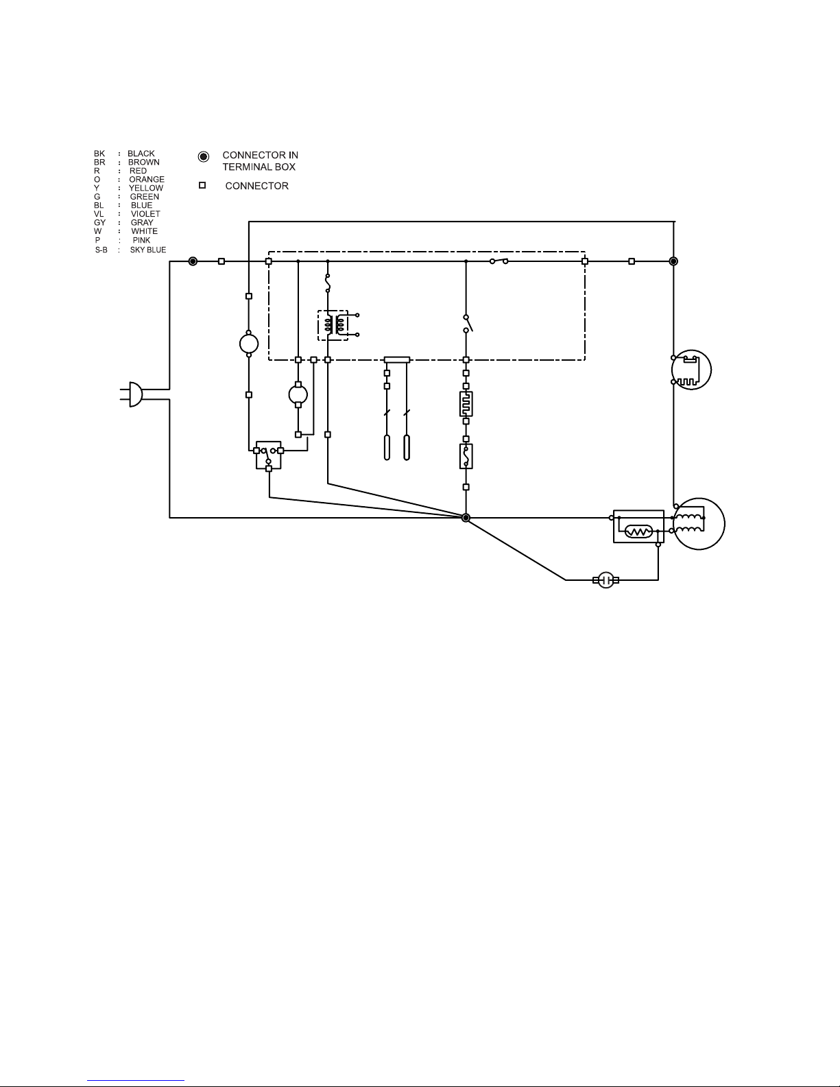
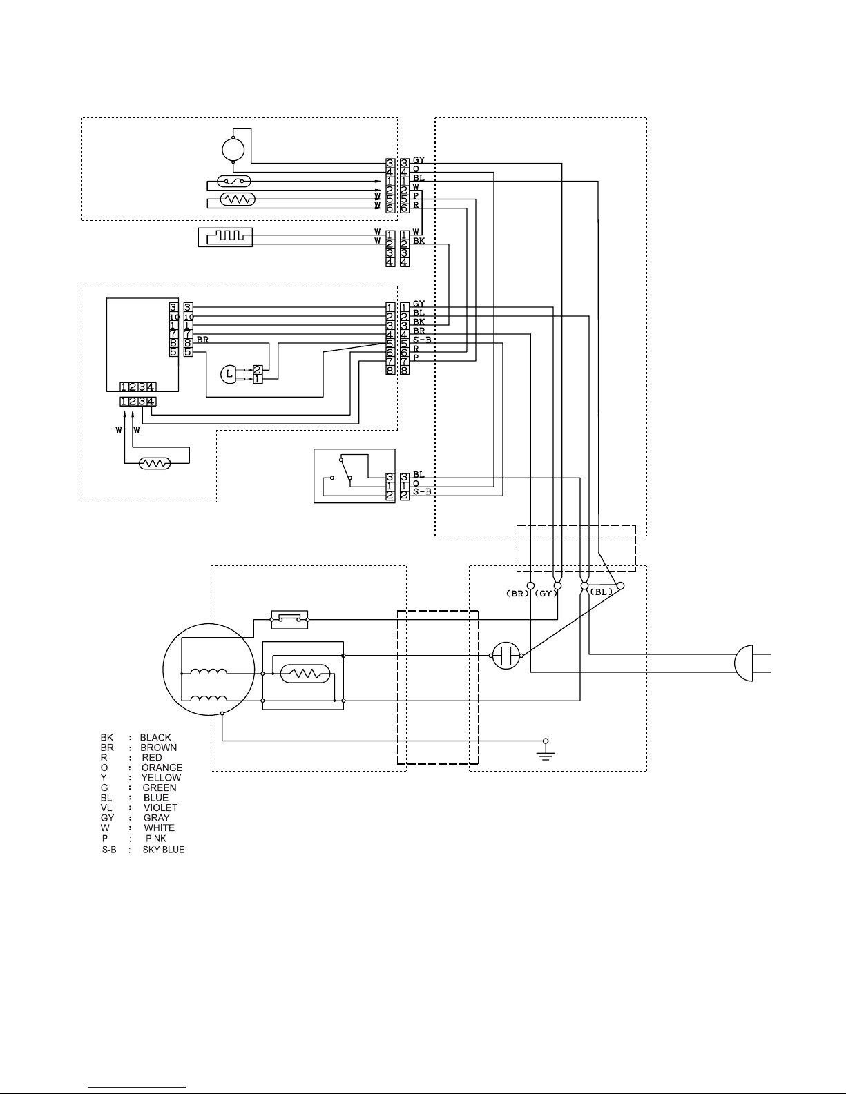
CHAPTER 5. WIRING DIAGRAM
[1] WIRING DIAGRAM
Be sure to replace the electrical parts with specified ones for maintaining the safety and performance of the set.
SOURCE CORD
(BR)
FAN MOTOR
FM
(O)
DOOR SWITCH
(BR)
L
LAMP
(S-B)
(BL)
DEF-THERMISTOR
R-THERMISTOR
22
FUSE
(W)
DEF-HEATER
(BK)
PWB
STARTING RELAY
COMPRESSOR
PROTECTOR
(GY)
RUNNING CAPACITOR
Page 11
SJD24NSLG
5 – 2
[2] ELECTRIC ACCESSORIES LAYOUT
F-LOUVER ASS’Y
FAN MOTOR
FM
LEAD EV COVER
FUSE
DEF-THERMISTOR
DEF-HEATER
R-CBOX-K
PWB
LAMP
R-THERMISTOR
DOOR SWITCH
TERMINAL COVER
COMPRESSOR
PROTECTOR
STARTING RELAY
CABINET
HARNESS FL ASS’Y
SOURCE CORD
RELAY WIRE ASS’Y
(BOTTOM ANGLE)
RUN CAP.
Page 12

SJD24NSLG
6 – 1
SJD24NSLG
Service Manual
CHAPTER 6. FAILURE DIAGNOSIS
[1] OUTLINE OF CONTROL
1. ON/OFF Control of Compressor
When the plug of refrigerator is connected, the compressor will start automatically and run for approximately 5 minutes. After then, ON/OFF of the
compressor will be controlled depend on the temperature detected by the R-thermistor. During 6 minutes after the compressor stops, it will not start
regardless of the detected temperature by R-thermistor..
2. Defrosting
Microcomputer calculates the appropriate timing of defrosting and defrosting is made automatically. Therefore no manual operation by user is
required. The cycle of defrosting varies depend on the usage condition of the refrigerator. (Maximum time 50 hours, minimum time 4 hours)
3. Thermistor
Thermistors are installed in 2 places; in the refrigerator compartment and close to the
Evaporator. (R-thermistor and Def-thermistor)
It is not installed in the freezer compartment.
R-thermistor reads the temperature in the refrigerator compartment and controls ON/OFF
of compressor.
Def-thermistor detects the temperature around the evaporator and shows the progress of
defrosting.
[2] CHECK MODE OF DEFROST HEATER (Forced Defrosting)
The operation of the defrost heater can be checked by starting it.
In case the failure of defrosting is suspected, this is an effective inspection method.
1. Starting Method
At the power OFF condition.
1) Keep the door of the refrigerator compartment open.
2) Set the Temp. Control Knob in the refrigerator compartment to the following position.
220-240V models: Center
110-127V models: Max
3) Keep the door open and supply power source.
2. Normal Operation
1) Approximately 3 seconds after power supply, the relay on the PWB will be turned ON and the defrost heater will be electrified for 5 seconds.
2) After 5 seconds, if the temperature of Def-thermistor reaches high enough (over 10°C) and judged as defrosting completion, the compressor runs
for 5 minutes and then returns to the normal control.
On the other hand, if the temperature of Def-thermistor is still low (under 10°C), the defrost heater will be electrified until the temperature of Def-
thermistor reaches the specified temperature or higher.
After completion of electrification, the compressor runs for 5 minutes and then returns to the normal control.
* In the case that any abnormality in Door Switch, Volume, R-thermistor or Def-thermistor, or the Temp. Control Knob is not in the position corre-
sponding to the value of the rating voltage settled to the PWB itself, this mode will not be entered nor the defrost heater is electrified.
Def-thermistor
Evaporator
Defrost heater
R-thermistor
PWB
Compressor
(Center)
Page 13

SJD24NSLG
6 – 2
[3] RE-SETTING OF MICROCOMPUTER AT POWER FAILURE
• At the power failure for over 0.1 second, the control of the microcomputer will be reset.
When the power is re-supplied, the temperature of R-thermistor will be detected again and ON/OFF of the compressor will be decided.
• At the momentary power failure (less than 0.1 second), the protector of the compressor might work due to the high load to the compressor for restarting.
• When resetting is made during the operation of the defrost heater, the normal cooling will be resumed.
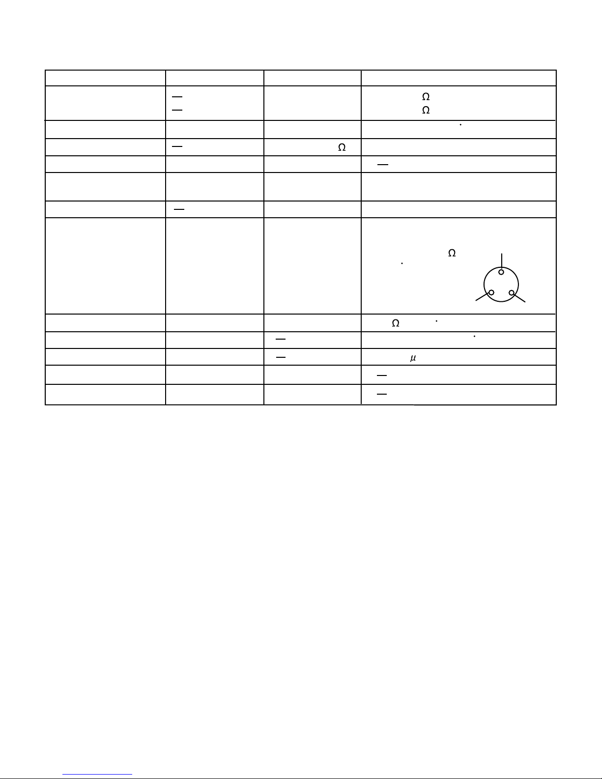
[4] DIAGNOSIS METHOD OF FAILURE
Check by the following procedure;
1. Disconnect power supply and check the following point.
• Is there any failure portion in inserting connectors?
2. Detach the PWB and check the appearance.
• Is there any burning or abnormal damage?
3. Check the conditions of the fuse and the varistor. (Fuse and varistor are located at the position in the figure.)
• Melting in the fuse cannot be checked visually (as the safer one than transparent glass tube is used). Be sure to detach the connector “CN1”
before measuring the resistance between the both ends of the fuse by the tester.
• Next, measure the resistance value between the both leads of the varistor.
4. Check whether the temperature (resistance value) shown by R-thermistor is correct or not. (Refer to the table below.)
• Detach the connector “CN3” on the PWB and measure the resistance value between 1 and 2 pins.
5. Check whether the temperature (resistance value) shown by Def-thermistor is correct or not. (Refer to the table below.)
• Detach the connector “CN3” on the PWB and measure the resistance value between 3 and 4 pins.
Var isto r→
Normal (several hundreds Ω~several KΩ) Damage
Fuse↓
Melting
Flow of excessive current is considerable for some reasons.
Check for any portion to cause short circuits especially
on the primary circuit.
There is a possibility of excessive voltage applied from outside with the factor such as thunder etc. When repeated
with a factor other than thunder, there might be the apparatus near by generating noises.
Conduction
Fuse and varistor are normal.
Possibility to be caused by excessive current or voltage
near the power supply is low. Proceed to the next check
item.
—
Fuse
Varistor
Page 14

SJD24NSLG
6 – 3
[5] CONVERSION TABLE
Conversion Table between R-thermistor and Def-thermistor Temperature and Resistance Value
Temperature
(°C)
Resistance Value
(kΩ)
Temperature
(°C)
Resistance Value
(kΩ)
Temperature
(°C)
Resistance Value
(kΩ)
-2 5 26.1 -11 11.49 3 5 .5
-24 24.54 -10 10.88 4 5.23
-23 23.08 -9 10.3 5 4.98
-22 21.72 -8 9.75 6 4.74
-21 20.46 -7 9.24 7 4.52
-20 19.27 -6 8.76 8 4.3
-19 18.16 -5 8.3 9 4.1
-18 17.13 -4 7.87 10 3.91
-17 16.16 -3 7.47 11 3.73
-16 15.25 -2 7.09 12 3.56
-15 14.4 -1 6.74 13 3.4
-14 13.6 0 6.4 14 3.24
-13 12.85 1 6.08 15 3.1
-12 12.15 2 5.78
Page 15

SJD24NSLG
6 – 4
[6] CIRCUIT DIAGRAM OF MAIN PWB
Page 16

SJD24NSLG
7 – 1
SJD24NSLG
Service Manual
CHAPTER 7. FUNCTIONS
[1] ADJUSTABLE TEMPERATURE CONTROL
1. Temperature control
1) FREEZER COMPARTMENT
The FREEZER TEMP. CONTROL regulates the quantity of cold air to the freezer.
"MAX" setting directs more cold air to the freezer compartment. (making the freezer compartment colder)
"MIN" setting directs less cold air to the freezer compartment. (making the freezer compartment less colder)
2) REFRIGERATOR COMPARTMENT
The REFRIGERATOR TEMP. CONTROL controls the compressor running time of the refrigeration system.
"Coldest"(5) setting will result in colder temperature in the both (refrigerator and freezer) compartments.
"MIN"(1) control setting will result in warmer temperature in the both (refrigerator and freezer) compartment.
NOTE:
• For hot summer conditions (about over 35 °C ambient temperature), set your FREEZER TEMP. CONTROL to less colder than "MID"
(towards "MIN"). This is because "MAX" setting may result in too little air flow to the refrigerator compartment, causing too warm temperature in the refrigerator compartment. And set your REFRIGERATOR TEMP. CONTROL to colder than the center position.
• In a cold kitchen (about under 10 °C ambient temperature), set your FREEZER TEMP. CONTROL to "MAX" to avoid too warm tempera-
ture in the freezer compartment. This is because the compressor operation is too short in winter, and not enough cold air is provided to
the freezer compartment. And if the foods in the refrigerator compartment freeze, you must set the REFRIGERATOR TEMP. CONTROL to
less colder setting. (toward "MIN").
• With the FREEZER TEMP. CONTROL set to "MAX" , there will be less cold air directed to the refrigerator compartment, and the refrigerator compartment may not become cold enough.
2. Reference value of temperature
The values tables above refer to the measurement carried out center area and 1/3 of overall height from the bottom at each of the refrigerator and the
freezer after the machine has been operated at an ambient temperature of 32 °C with no food stored and the door closed until the temperature is sta-
bilized.
The values vary depending upon frequency of opening and closing, the doors ambient temperature, amount of stored foods and manner of storing
foods.
KNOB
SETTING
MAX
MID
MIN
PURPOSE
For making ice rapidly of fast freezing. And winter season.
When restocking with fresh food.
For normal freezing.
For storing frozen food for a short period (up to one month).
When frozen food or ice cream is not stored.
FREEZER TEMP.CONTROL
KNOB
SETTING
MIN
MAX
(Center)
PURPOSE
For keeping freshness of food longer.
When the refrigerator does not provide sufficient cooling.
For normal operation.
When the refrigerator provides excessive cooling.
When refrigerator temperature control sets to the "MAX", some foods stored
may become frozen. In this case adjust control set back to the center position.
REFRIGERATOR
TEMP.CONTROL
SETTING OF
FREEZER TEMP.
CONTROL KNOB
Freezer
temperature
MAX
(Coldest)
MID
Approx.
Approx. Approx.
The values shown above refer to the case where the
refrigerator temp. control knob is set at
the center position
.
SETTING OF
REFRIGERATOR TEMP.
CONTROL KNOB
Refrigerator
temperature
MAX
(Coldest)
MIN
Approx.
Approx. Approx.
The values shown above refer to the case where the
freezer temp. control knob is set at
"MID"
.
(Center)
MIN
Page 17

SJD24NSLG
7 – 2
3. Temp. control system
Ambient temperature
Refrigerator compartment temperature (at the center position)
Freezer compartment temperature (at MID position)
0
Normal operation (ex. at 20 C ambient temperature)
ON
Compressor & Fan
10
20
30
-20
-10
Time
OFF
OFF
ON
Temp.(C)
FREEZER
COMPARTMENT
FREEZER
COMPARTMENT
REFRIGERATOR
COMPARTMENT
REFRIGERATOR
COMPARTMENT
Evaporator
Cold air
Fan
Compressor
much cold air
less cold air
FREEZER
COMPARTMENT
REFRIGERATOR
COMPARTMENT
low cold power
less cold air
regulating the quantity
of cold air.
much cold air
regulating the quantity
of cold air.
controlling the compressor
& the fan running time
high cold power
controlling the compressor
& the fan running time
Freezer Temp. Control Knob
The FREEZER TEMP. CONTROL regulates the quantity of cold air to the freezer.
MAX
setting directs more cold air to the freezer compartment.
(making the freezer compartment colder)
MIN
setting directs less cold air to the freezer compartment.
(making the freezer compartment less colder)
Refrigerator Temp. Control Knob
The REFRIGERATOR TEMP. CONTROL controls the
compressor & the fan running time of the refrigerator system.
MAX
setting will result in colder temperature in the both
(refrigerator and freezer) compartments.
MIN
control setting will result in warmer temperature in the
both (refrigerator and freezer) compartments.
Coldest Coldest
Page 18

SJD24NSLG
8 – 1
SJD24NSLG
Service Manual
CHAPTER 8. ASSEMBLING PROCEDURES OF MAIN PARTS AND CAUTIONS
CAUTION: DISCONNECT THE UNIT FROM THE POWER SUPPLY BEFORE ANY REPAIRING.
[1] F-LOUVER ASS'Y
1. Fan motor ass'y
1. Stick U-sealer handle to Fan motor holder b (Fig. A-2).
2. Insert the terminal of Lead EV-cover to Fan motor (Fig. A-3).
3. Insert shaft of Fan motor to the hole of motor cushion, set at Fan motor holder b.
Then insert the boss of rear to the hole of Motor cushion, fix with Tapping screw(1 piece).
4. Set Fan clamp to propeller fan 90 mm. and then insert it to the shaft of Fan motor( Fig. A-4).
Fan motor holder b
U-sealer handle
U-sealer handle
Motor cushion
Lead EV-cover
Fan motor
Motor cushion
Fan motor holder a
Propeller fan 90
Fan clamp
Slit area
Figure A-1
Fan motor holder b
U-sealer handle
U-sealer handle
Fan motor holder b
Lead EV-cover
Fan motor
Fan clamp
Propeller fan 90
Detail of D
Propeller fan 90
Fan clamp
Fan motor
Motor cushion
Motor cushion
Fan motor holder b
Fan motor holder a
Note
(1) Assemble so that terminal of Fan motor does not deform.
(2) Take care not to stress to terminals of Fan motor after wiring.
(3) Check locking by pulling them with more than 10N(1 kgf).
Note
(1) Slit of each Fan Clamp and propeller fan 100 should not be at same
position.
(2) Fan clamp should be inserted virtically to the end of boss.
(3) Propeller fan should not be taken out from shaft when pulled by 2 kgf.
(127V : with yellow tape)
WIRE COLOR IS GRAY/ORANGE
GOOD NO GOOD
slit
Fan clamp
slit
SEC. A-A
Figure A-4
Figure A-2
Figure A-3
Page 19

SJD24NSLG
8 – 2
2. EV-cover ass'y
1. Bind Fuse ass'y with L-band c. Then wind glass cloth tape (W25 x L50mm ) to lead wire of Fuse ass'y (Figure A-5).
2. Stick EVC-sealer a to square hole of EV-cover.
3. Set Fan motor ass'y to EV-cover. Then Fix with 2 tapping screw(Figure A-6) .
4. Set Fuse ass'y to EV-cover then stick aluminum tape (W39 x L35mm) and EV-cover al to EV-cover.
5. Set Def-thermistor to EV-cover and fix to Fan motor holder b with aluminum tape (W39 x L50mm ).
6. Insert the terminal of Def-thermistor to terminal no.5/No.6 and then insert the Fuse ass'y to the terminals No.1/No.2. on the 6P connector of Lead
EV-cover (Figure A-7).
7. After wiring at rear of EV-cover take out lead wire from square hole to front and fix with L-band c. Then stick EVC-sealer b to lead wire.
Fuse ass’y
L-band c
Glass cloth tape
W25xL50
Figure A-5
Note
Fan motor ass’y
Tapping screw
Def-thermistor
W25xL50
Glass cloth tape
Stick Al-tape
from here
Aluminum tape
W39xL135
L-band c
SEC. D-D
SCALE 2:1
FUSE
(BLACK) (BLUE)
(WHITE)
Fan motor ass’y
T
(BLACK) (BLUE)
(WHITE)
Pins should be inserted surely, and check by pulling it.
PL Process
Note
Figure A-7
Figure A-6
FAN MOTOR
DEF THERMISTOR
Lead wire of Fuse ass’y must not over
EV-cover.
Lead EV-cover
Tapping screw
L-band c
EVC-sealer a
EVC-sealer b
Fuse ass’y
Tapping screw
L-band c
EV-cover al
Stick EV-cover al
from this line
(GRAY/ORANGE)
Page 20

SJD24NSLG
8 – 3
3. F - louver ass'y
1. Set F-louver to front side of EV-cover with double face tape (W15xL45mm.).
2. Insert F-control knob to F-louver. Then set to front side of EV-cover.
3. Stick EVC-sealer c to bottom of F-louver ass'y.
F-louver
F-control knob
EVC-sealer c
F-louver
Fan motor holder a
Fan motor holder b
F-louver
F-control knob
Fan motor holder a
Fan motor holder b
EV-cover
NO CLEARANCE
Double face tape
W15xL45
more than 3.5mm. more than 3.5mm.
Figure A-8
Lead EV-cover
EV-cover
F-louver
F-control knob
arm B
F- louver
arm A
F-control knob
F-louver
F-control knob
SEC. B-B SEC. C-C
Attachment specification of the F-control knob
arm B
The F-control knob is inserted into the ditch of the fan louver.
EV-cover
EV- cover
arm A
Figure A-9
Page 21

SJD24NSLG
8 – 4
[2] R CONTROL COV. ASS'Y
1. Insert Lead R-Thermistor to Lead R-C Box.
2. Inset Lead R-C box to PWB L ass'y.
3. Assemble the PWB L ass’y with PWB holder A and then assemble the PWB holder A with PWB holder B.
4. Stick the R-control AL on PWB holder A/B ass’y.
Lamp
R-C Box cover
Control label
R-Control knob
Figure A-10
Lead R-Thermistor( White wire)
Lead R-C Box
Lead R-C Box
PWB holder B
PWB holder A
Lead sealer
Figure A-11
PWB holder A
R-control AL
PWB holder B
Page 22

SJD24NSLG
8 – 5
5. Assemble Lamp with R-C Box cover then fix with 2 tapping screw.
6. Stick Knob sealer on R-C Box cover and then insert Knob joint to R-C Box cover.
7. Assemble the PWB ass'y with R-C Box cover. And place the R-Thermistor on the groove of R-C Box cover.
8. Insert Lead R-C Box to Lamp.
9. Insert R-Control knob to R-C Box cover.
10.Stick Control Label on R-C Box cover.
R-C Box cover
Knob sealer
R-C Box cover
Knob joint
Figure A-12
PWB holder
R-Thermistor
R-C Box cover
Lamp
Figure A-13
Control label
R-Control knob
Figure A-14
Page 23

SJD24NSLG
8 – 6
[3] HOW TO REPLACE THE LAMP
1. Remove the Light cover.
2. Remove the 2 screw, and pull the Lamp out.
3. Insert the new Lamp to the connector, and fix with 2 screws.
4. Set the Light cover.
Screw
Page 24

SJD24NSLG
8 – 7
[4] DEFROST HEATER
1. Taking-out Evaporator
1. Take-out Fan louver ass’y.
2. Take-out E.V cover ass’y.
3. As shown in Figure A-15, pull the upper part of Evaporator toward
you, pull it diagonally so that the pipe of Evaporator does not contact the convex part of food liner.
4. Pull the Evaporator for remove as shown in Figure A-16.
NOTE: When pulling Evaporator and bending the pipes,pay attention
so as not to break and deform the pipes. Still, take care not to
hurt yourself by fin of Evaporator.
2. Replacement of Def. heater.
1. Remove the aluminium tape on Heater support to take it off from
the food liner.
2. Raise the protrusion part of Heater support. Then remove Heater
cover.
3. Open Def.heater fixed part of Heater support al to the right and left,
then remove Def.heater ass’y.
Evaporator
Food liner convex part
Figure A-15
Food liner convex part
Evaporator
Pipe
Figure A-16
Evaporator
Figure A-17
Heater cover
Protrusion parts
Protrusion part of Drain support al(2 pcs.)
Heater cover
Def. heater ass'y
Heater support
Figure A-18
Heater support
Fixed parts
Def.heater ass’y
Figure A-19
Page 25

SJD24NSLG
8 – 8
4. Replace Def. heater ass’y with new one.
5. Bend end of heater support 90.
6. Assemble Defrost heater to Heater Support.
7. Assemble Heater cover to Heater Support. Bend top edge to outside.
8. Roll the leading wire Sealer to Lead wire Defrost Heater.
3. Installing of Evaporator
1. Install Evaporator as shown in Figure.A-15 in the reverse order of
Figure.A-16.
2. Correct the deformed fin.
NOTE: 1.When installing Evaporator, take care not to deform signifi-
cantly and break the pipes.
2.Take care not to damage the lead wires and hurt yourself by
the fin of Evaporator.
3.You shouldn’t touch Defrost Heater with your bare hand.
(you should were pure gloves)
4.You should wipe that with alcohol. When you touch Defrost
heater with your bare hand.
Heater support
Def. heater ass'y
Heater cover
Figure A-20
Heater Support
BEND
BEND
Figure A-21
4P
Defrost Heater
Heater
support
Figure A-22
4P
BEND
BEND
Figure A-23
Page 26

SJD24NSLG
9 – 1
SJD24NSLG
Service Manual
CHAPTER 9. COOLING UNIT
[1] COOLING UNIT
NOTE: The iron pipe is partly used of this refrigerator. Please note the following points when brazing the iron pipe.
• Brazing material should be silver brazing rod. (To be equivalent with BAg-20 or BAg-7)
• Flux should be FB3A type. (It should be non-chlorine type).
• Place an iron plate or cloth on the base frame to prevent the flux fall.
• Remove the paint and plating on the pipe by the sandpaper before start repairing.
• If you cut the iron pipe for repairing, remove the plating on the iron pipe end (20mm) by the sandpaper.
• Put the flux on silver brazing rod and dry the flux by the flame of the torch, and then start brazing.
• Remove the flux completely by the wire brush , and wipe off by the cloth after brazing.
• Leakage inspection should be done when compressor is running.
• After removing flux, paint the black enamel paint on the brazing part.
* Copper back condenser is used in some models.Before repairing,check the Back condenser is copper or iron.
Hot pipe L
(Side condenser)
Hot pipe
(DP-condenser)
Hot pipe R
(Side condenser)
Evaporator
Suction pipe
Compressor
Capillary tube
Dryer
Back condenser
S.P connector
Discharge P connector
Dryer connector
Mark: Brazing portion
Mark: Refrigerant flow
Iron pipe
Iron pipe
Page 27

SJD24NSLG
9 – 2
[2] LOCATION
1. Location 1
2. Location 2
* Copper back condenser is used in some models.Before repairing,check the Back condenser is copper or iron.
Capillary tube
Dryer
Charge pipe
Dryer connector
Charge pipe L
Suction pipe S.P
connector
Discharge
P connector
Evaporator
Compressor
Back condenser
Hot pipe
Mark shows Ag brazing points
Mark shows Cu brazing points
*
Charge pipe
to Dryer
Dryer connector
to Dryer
Hot pipe
to Dryer connector
Pinch Point
Dryer
to Capillary tube
Compressor's discharge pipe
Suction butyl
to Discharge P. connector
Charge pipe L
to Compressor's
process tube
Back condenser
to Hot pipe
D.P. butyl
Discharge P. connector
to Back condenser
Pinch point
S.P connector
to Compressor's
suction tube
S.P connector
to Suction pipe
Mark shows Ag brazing points
Mark shows Cu brazing points
*
Page 28

PartsGuide
SJ-D20N/D24N/D28N/D29N-SLG
PARTS GUIDE
Refrigerator-freezer
MODELS
CONTENTS
SJ-D20N-SLG
SJ-D24N-SLG
SJ-D28N-SLG
SJ-D29N-SLG
[1] SJ-D20N/D24N/D28N/D29N-SLG
ELECTORIC,MECHANICAL,CYCL
E PARTS
[2] SJ-D20N/D24N/D28N/D29N-SLG
DOOR,ATTACHMENT PARTS
[3] SJ-D20N/D24N/D28N/D29N-SLG
OTHER PARTS
INDEX
This document has been published to be used
for after sales service only.
The contents are subject to change without notice.
Page 29

SJD24NSLG
[1] SJ-D20N/D24N/D28N/D29N-SLG ELECTORIC,MECHANICAL,CYCLE PARTS
6-11
2-1
2-33
2-34
2-32
1-13
2-47
2-28
2-29
2-35
2-19
2-45
2-9
1-14
2-40
1-11
2-51
2-48
2-36
2-37
2-18
1-7
2-49
2-26
2-46
2-22
1-12
1-6
2-20
1-4
2-39
4-2
2-23
1-5
2-3
2-21
2-5
6-8
1-1
6-18
6-3
2-4
6-5
2-25
6-6
2-24
6-5
6-1
2-2
6-15
6-14
6-19
6-24
6-12
2-10
2-15
1-2
2-41
2-16
4-3
6-4
2-42
1-15
1-3
2-17
2-11
4-4
2-6
1-20
1-8
2-30
NO. PARTS CODE
PRICE
RANK
[1] SJ-D20N/D24N/D28N/D29N-SLG ELECTORIC,MECHANICAL,CYCLE PARTS
1-1 QSW-PA092CBZA AH Door switch
1-2 FCNW-A900CBKZ AZ Relay wire ass'y
1-3 QACC-A154CBZZ AM Source cord
1-4 FPWB-A451CBKZ BQ Pwb l ass'y [D20N][D24N][D28N]
1-4 FPWB-A490CBKZ BQ Pwb l ass'y [D29N]
1-5 FW-VZA157CBZZ AP Lead rc-box
1-6 RH-HXA097CBZZ AT R-thermistor
1-7 RLMP-A037CBZZ BD Lamp
1-8 RHOG-A199CBZZ AW Protector
1-9 RSTT-A196CBZZ AU Starting relay
1-11 FFS-TA093CBKZ AP Fuse ass'y [D20N][D24N]
2-31
2-50
NEW
MARK
PAR T
RANK
4-1
6-23
6-2
6-21
1-9
6-20
6-9
6-22
6-7
DESCRIPTION
2
Page 30

SJD24NSLG
NO. PARTS CODE
PRICE
RANK
NEW
MARK
PAR T
RANK
DESCRIPTION
[1] SJ-D20N/D24N/D28N/D29N-SLG ELECTORIC,MECHANICAL,CYCLE PARTS
1-11 FFS-TA094CBKZ AR Fuse ass'y [D28N][D29N]
1-12 FW-VZA156CBZZ AH Lead ev cover
1-13 RH-HXA098CBZZ AT Def-thermistor
1-14 RMOTRA057CBE0 AZ Fan motor
1-15 FHETBA201CBZZ AV Defrost heater [D20N][D24N]
1-15 FHETBA202CBZZ AV Defrost heater [D28N][D29N]
1-20 RC-EZA237CBZZ BC Running capacitor
2-1 GCOV-A289CBFA AG Top hinge cover
2-2 DHNG-A575CBMZ AG Top hinge ass'y
2-3 FCABCA630CBKZ BC C-plaet ass'y
2-4 DHNG-A579CBMZ AG Center hinge
2-5 FAJS-A006CBFA AF Adjustable leg ass'y
2-6 LBND-A018CBE0 AP Fastening band a
2-9 PCOV-A344CBFA AK Lamp cover
2-10 PSHEMA311CBZZ AE Fl-al sheet
2-11 LHLD-A359CBFA AE T-box holder
2-15 USRA-A309CBFA AR Evaporation pan
2-16 PBOX-A084CBFA AG Terminal box
2-17 PCOVPA184CBFA AF Terminal cover
2-18 GCOVPA210CBFA AQ Rc-box cover
2-19 JKNB-A071CBFA AF R-control knob
2-20 PCOVPA415CBFA AG Pwb holder-a
2-21 PCOVPA416CBFA AG Pwb holder-b
2-22 PSEL-C696CBZZ AD Knob sealer
2-23 PSEL-C697CBZZ AD Lead sealer
2-24 DHNG-A577CBMZ AG Bottom hinge ass'y
2-25 GLEGPA008CBFA AD Leg
2-26 JKNB-A073CBFA AF Knob joint
2-28 PFIL-A050CBEZ AM Deodorizer
2-29 HGRL-A249CBFA AG Deo.louver
2-30 HGRL-A247CBFA AL R-louver [D24N][D28N][D29N]
2-30 HGRL-A252CBFA AQ R-louver [D20N]
2-31 PFPFPB597CBFZ AG R-lover duct [D24N][D28N][D29N]
2-31 PFPFPB609CBFZ AF
2-32 GCOV-A290CBFA AP Ev-cover [D20N][D24N]
2-32 GCOV-A291CBFA AP Ev-cover [D28N][D29N]
2-33 HGRL-A248CBFA AP F-louver [D20N][D24N]
2-33 HGRL-A250CBFA AR F-louver [D28N][D29N]
2-34 JKNB-A072CBFA AF F-control knob
2-35 LCRA-A018CBEZ AD Fan clamp [D20N]
2-35 LCRA-A022CBPZ AC Fan clamp [D24N][D28N][D29N]
2-36 LHLD-A389CBF0 AF Motor cushion
2-37 LHLD-A732CBFA AK Fm-holder a
2-39 LHLD-A733CBFA AK Fm-holder b
2-40 NFANPA012CBF0 AD Propeller fan 90
2-41 LPLTMA755CBPZ AN Heater support
2-42 PSHEMA309CBPZ AG Heater cover
2-45 PSEL-C690CBZZ AD Evc-sealer a
2-46 PSEL-C691CBZZ AD Evc-sealer b
2-47 PSEL-C692CBZZ AD Evc-sealer c
2-48 PSHEMA310CBZZ AE Ev-cover al
2-49 PSEL-B209CBE0 AB U-sealer handle
2-50 PSEL-C689CBZZ AE A-sealer r-duct [D24N][D28N][D29N]
2-50 PSEL-C703CBZZ AD A-sealer r-duct [D20N]
2-51 PSHEMA318CBZZ AF R-control al
4-1 LX-BZA090CBZZ AC Special screw
4-2 LBND-A023CBE0 AC L-band c
4-3 QTAN-A012CBE0 AH Solderless term. b
4-4 QTAN-A013CBE0 AH Solderless term. a
6-1 PCMPLA272CBZZ BU Compressor
6-2 PSPAGA039CBE0 AE Rubber grommet
6-3 LFRMMA033CBPZ AT Base frame
6-4 PEVA-A162CBZZ BD Evaporator [D20N][D24N]
6-4 PEVA-A163CBZZ BD Evaporator [D28N][D29N]
6-5 PPIPCA252CBE0 AD Charge pipe
6-6 FDRY-A006CBK0 AX Dryer ass'y
6-7 PCLI-A055CBEZ AC Clip
LPLTMA399CBP0 AD Dryer support
6-8
6-9 PCOVPA418CBEZ AV Protect coverr
6-11 PKYU-A035CBE0 AG Sp-butyl h
6-12 PKYU-A121CBE0 AC D.p.butyl
6-14 PPIPCA563CBEZ AN Discharge p.conecter
6-15 PPIPCA541CBEZ AM S.p connector
6-18 PPIPCA551CBZZ AF Drier connector
6-19 PKYU-A098CBE0 AG Compressor butyl
6-20 LHLD-A781CBEZ AG Cord clip
6-21 LX-BZA107CBZZ AD Earth screw
6-22 LX-CZA017CBZZ AD Cord clip screw
6-23 PSPAFA031CBE0 AD Sleeve
6-24 LX-WZA035CBZZ AB Washer
R-lover duct [D20N]
3
Page 31

SJD24NSLG
[2] SJ-D20N/D24N/D28N/D29N-SLG DOOR,ATTACHMENT PARTS
3-4
3-9
3-5
3-6
3-6
3-7
3-3
3-3-1
3-2
3-3-2
3-8
3-7-1
5-2
5-4
5-15
5-14
5-9
5-5
5-1
5-6
5-12-3
5-16
5-8
5-11
5-12
5-12-2
3-3-2
5-5
5-3
5-13
5-17-2
5-12-1
5-7-1
5-12-1
5-7-2
5-17-1
5-18-2
5-18-1
5-12-2
5-18
5-17
5-7
5-7-4
5-7-3
5-10
4
Page 32

SJD24NSLG
NO. PARTS CODE
PRICE
RANK
NEW
MARK
PAR T
RANK
[2] SJ-D20N/D24N/D28N/D29N-SLG DOOR,ATTACHMENT PARTS
3-2 HBDGDB009CBZA AZ Badge
3-3 FDORFB913CBKZ BS F-door ass'y [D20N][D24N]
3-3 FDORFB914CBKZ BS F-door ass'y [D28N][D29N]
3-3-1 NBRGPA013CBFB AH Nylon bearing 2
3-3-2 LSTPPA155CBFA AG Door stopper
3-4 FPACGA444CBZA AS F door packing [D20N][D24N]
3-4 FPACGA447CBZA AT F door packing [D28N][D29N]
3-5 HDECQA518CBTA AP Handle trim-f [D20N][D24N]
3-5 HDECQA521CBTA AP Handle trim-f [D28N][D29N]
3-6 JHNDPA226CBFA BA Handle [D20N][D24N]
3-6 JHNDPA233CBFA AQ Handle [D28N][D29N]
3-7 FDORRB764CBKZ BT R-door ass'y [D24N]
3-7 FDORRB765CBKZ BT R-door ass'y [D28N]
3-7 FDORRB779CBKZ BS R-door ass'y [D20N]
3-7 FDORRB780CBKZ BT R-door ass'y [D29N]
3-7-1 NBRGPA014CBFB AH Nylon bearing 3
3-8 FPACGA446CBZA AT R door packing [D24N]
3-8 FPACGA448CBZA AV R door packing [D28N]
3-8 FPACGA451CBZA AU R door packing [D20N]
3-8 FPACGA452CBZA AW R door packing [D29N]
3-9 HDECQA517CBJA AN Handle trim-r [D20N][D24N]
3-9 HDECQA520CBJA AN Handle trim-r [D28N][D29N]
5-1 GDORPA079CBFA AL Fresh door
5-2 UPOK-A198CBFA AK Small pocket [D24N][D28N][D29N]
5-3 UPOK-A199CBFA AK Bottle pocket
5-4 UPOK-A200CBFA AH Egg pocket
5-5 UPOK-A201CBFA AH Door pocket
5-6 UTNA-A404CBFA AP F-shelf
5-7 FTNA-A441CBKZ AY V-shelf ass'y
5-7-1 HDECQA542CBFA AR V-shelf-dec-f
5-7-2 LHLD-A742CBFA AQ Shelf-holder-l
5-7-3 LHLD-A743CBFA AQ Shelf-holder-r
5-7-4 UTNA-A430CBZZ AV V-shelf
5-8 UTNA-A406CBFA AP
5-9 UYOK-A087CBFG AH Ice storage box
5-10 UYOK-A519CBFA AP Vegetable case
5-11 UYOK-A520CBFA AP Fresh case
5-12 FTNA-A431CBKZ AZ R-shelf ass'y [D24N][D28N][D29N]
5-12-1 HDECQA522CBFA AQ R-shelf-dec-f [D24N][D28N][D29N]
5-12-2 HDECQA523CBFA AQ R-shelf-dec-r [D24N][D28N][D29N]
5-12-3 UTNA-A416CBZZ AZ R-shelf [D24N][D28N][D29N]
5-13 FCAS-A033CBKZ AZ Carry case ass'y [D24N][D28N][D29N]
5-14 FSRA-A266CBKZ AX Ice cube maker
5-15 LRALPA140CBFA AG Ice tray holder l
5-16 LRALPA141CBFA AG Ice tray holder r
5-17 FTNA-A432CBKZ AZ R-shelf-l ass'y
5-17-1 HDECQA526CBFA AQ R-shelf-l-dec-r
5-17-2 UTNA-A417CBZZ AZ R-shelf-l
5-18 FTNA-A433CBKZ AZ R-shelf-s ass'y
5-18-1 HDECQA525CBFA AQ R-shelf-s-dec-f
5-18-2 UTNA-A418CBZZ AZ R-shelf-s
F-shelf s
[3] SJ-D20N/D24N/D28N/D29N-SLG OTHER PARTS
90-1 SPAKCA255CBZZ BA Packing case 34 [D29N]
90-1 SPAKCA257CBZZ BA Packing case 26 s-no [D24N]
90-1 SPAKCA258CBZZ BB Packing case 30 s-no [D28N]
90-1 SPAKCA266CBZZ AZ Packing case 22 s-no [D20N]
90-2 TINS-A741CBRZ AK Operation manual
90-3 TLAB-A939CBRZ AD Caution label rof
90-4 CPADBA084CBKZ AQ Bottom pad ass'y
90-5 CPADBA085CBKZ AQ Top pad ass'y
90-6 SPADBA363CBFZ AF Cushion-comp
90-10 CPADBA090CBKZ AQ Top pad t ass'y
90-11 TLAB-A876CBRZ AC Warning label
90-12 SPADBA333CBZZ AG Corner post b
DESCRIPTION
5
Page 33

SJD24NSLG
INDEX
PARTS CODE No.
[ C ]
CPADBA084CBKZ 3-90-4 AQ
CPADBA085CBKZ 3-90-5 AQ
CPADBA090CBKZ 3-90-10 AQ
[ D ]
DHNG-A575CBMZ 1-2-2 AG
DHNG-A577CBMZ 1-2-24 AG
DHNG-A579CBMZ 1-2-4 AG
[ F ]
FAJS-A006CBFA 1-2-5 AF
FCABCA630CBKZ 1-2-3 BC
FCAS-A033CBKZ 2-5-13 AZ
FCNW-A900CBKZ 1-1-2 AZ
FDORFB913CBKZ 2-3-3 BS
FDORFB914CBKZ 2-3-3 BS
FDORRB764CBKZ 2-3-7 BT
FDORRB765CBKZ 2-3-7 BT
FDORRB779CBKZ 2-3-7 BS
FDORRB780CBKZ 2-3-7 BT
FDRY-A006CBK0 1-6-6 AX
FFS-TA093CBKZ 1-1-11 AP
FFS-TA094CBKZ 1-1-11 AR
FHETBA201CBZZ 1-1-15 AV
FHETBA202CBZZ 1-1-15 AV
FPACGA444CBZA 2-3-4 AS
FPACGA446CBZA 2-3-8 AT
FPACGA447CBZA 2-3-4 AT
FPACGA448CBZA 2-3-8 AV
FPACGA451CBZA 2-3-8 AU
FPACGA452CBZA 2-3-8 AW
FPWB-A451CBKZ 1-1-4 BQ
FPWB-A490CBKZ 1-1-4 BQ
FSRA-A266CBKZ 2-5-14 AX
FTNA-A431CBKZ 2-5-12 AZ
FTNA-A432CBKZ 2-5-17 AZ
FTNA-A433CBKZ 2-5-18 AZ
FTNA-A441CBKZ 2-5-7 AY
FW-VZA156CBZZ 1-1-12 AH
FW-VZA157CBZZ 1-1-5 AP
[ G ]
GCOV-A289CBFA 1-2-1 AG
GCOV-A290CBFA 1-2-32 AP
GCOV-A291CBFA 1-2-32 AP
GCOVPA210CBFA 1-2-18 AQ
GDORPA079CBFA 2-5-1 AL
GLEGPA008CBFA 1-2-25 AD
[ H ]
HBDGDB009CBZA 2-3-2 AZ
HDECQA517CBJA 2-3-9 AN
HDECQA518CBTA 2-3-5 AP
HDECQA520CBJA 2-3-9 AN
HDECQA521CBTA 2-3-5 AP
HDECQA522CBFA 2-5-12-1 AQ
HDECQA523CBFA 2-5-12-2 AQ
HDECQA525CBFA 2-5-18-1 AQ
HDECQA526CBFA 2-5-17-1 AQ
HDECQA542CBFA 2-5-7-1 AR
HGRL-A247CBFA 1-2-30 AL
HGRL-A248CBFA 1-2-33 AP
HGRL-A249CBFA 1-2-29 AG
HGRL-A250CBFA 1-2-33 AR
HGRL-A252CBFA 1-2-30 AQ
[ J ]
JHNDPA226CBFA 2-3-6 BA
JHNDPA233CBFA 2-3-6 AQ
JKNB-A071CBFA 1-2-19 AF
JKNB-A072CBFA 1-2-34 AF
JKNB-A073CBFA 1-2-26 AF
[ L ]
LBND-A018CBE0 1-2-6 AP
LBND-A023CBE0 1-4-2 AC
LCRA-A018CBEZ 1-2-35 AD
LCRA-A022CBPZ 1-2-35 AC
LFRMMA033CBPZ 1-6-3 AT
LHLD-A359CBFA 1-2-11 AE
LHLD-A389CBF0 1-2-36 AF
LHLD-A732CBFA 1-2-37 AK
LHLD-A733CBFA 1-2-39 AK
LHLD-A742CBFA 2-5-7-2 AQ
PRICE
RANK
NEW
MARK
PAR T
RANK
PARTS CODE No.
LHLD-A743CBFA 2-5-7-3 AQ
LHLD-A781CBEZ 1-6-20 AG
LPLTMA399CBP0 1-6-8 AD
LPLTMA755CBPZ 1-2-41 AN
LRALPA140CBFA 2-5-15 AG
LRALPA141CBFA 2-5-16 AG
LSTPPA155CBFA 2-3-3-2 AG
LX-BZA090CBZZ 1-4-1 AC
LX-BZA107CBZZ 1-6-21 AD
LX-CZA017CBZZ 1-6-22 AD
LX-WZA035CBZZ 1-6-24 AB
[ N ]
NBRGPA013CBFB 2-3-3-1 AH
NBRGPA014CBFB 2-3-7-1 AH
NFANPA012CBF0 1-2-40 A D
[ P ]
PBOX-A084CBFA 1-2-16 AG
PCLI-A055CBEZ 1-6-7 AC
PCMPLA272CBZZ 1-6-1 BU
PCOV-A344CBFA 1-2-9 AK
PCOVPA184CBFA 1-2-17 AF
PCOVPA415CBFA 1-2-20 AG
PCOVPA416CBFA 1-2-21 AG
PCOVPA418CBEZ 1-6-9 AV
PEVA-A162CBZZ 1-6-4 BD
PEVA-A163CBZZ 1-6-4 BD
PFIL-A050CBEZ 1-2-28 AM
PFPFPB597CBFZ 1-2-31 AG
PFPFPB609CBFZ 1-2-31 AF
PKYU-A035CBE0 1-6-11 AG
PKYU-A098CBE0 1-6-19 AG
PKYU-A121CBE0 1-6-12 AC
PPIPCA252CBE0 1-6-5 AD
PPIPCA541CBEZ 1-6-15 AM
PPIPCA551CBZZ 1-6-18 AF
PPIPCA563CBEZ 1-6-14 AN
PSEL-B209CBE0 1-2-49 AB
PSEL-C689CBZZ 1-2-50 AE
PSEL-C690CBZZ 1-2-45 AD
PSEL-C691CBZZ 1-2-46 AD
PSEL-C692CBZZ 1-2-47 AD
PSEL-C696CBZZ 1-2-22 AD
PSEL-C697CBZZ 1-2-23 AD
PSEL-C703CBZZ 1-2-50 AD
PSHEMA309CBPZ 1-2-42 AG
PSHEMA310CBZZ 1-2-48 AE
PSHEMA311CBZZ 1-2-10 AE
PSHEMA318CBZZ 1-2-51 AF
PSPAFA031CBE0 1-6-23 AD
PSPAGA039CBE0 1-6-2 AE
[ Q ]
QACC-A154CBZZ 1-1-3 AM
QSW-PA092CBZA 1-1-1 AH
QTAN-A012CBE0 1-4-3 AH
QTAN-A013CBE0 1-4-4 AH
[ R ]
RC-EZA237CBZZ 1-1-20 BC
RH-HXA097CBZZ 1-1-6 AT
RH-HXA098CBZZ 1-1-13 AT
RHOG-A199CBZZ 1-1-8 AW
RLMP-A037CBZZ 1-1-7 BD
RMOTRA057CBE0 1-1-14 AZ
RSTT-A196CBZZ 1-1-9 AU
[ S ]
SPADBA333CBZZ 3-90-12 AG
SPADBA363CBFZ 3-90-6 AF
SPAKCA255CBZZ 3-90-1 BA
SPAKCA257CBZZ 3-90-1 BA
SPAKCA258CBZZ 3-90-1 BB
SPAKCA266CBZZ 3-90-1 AZ
[ T ]
TINS-A741CBRZ 3-90-2 AK
TLAB-A876CBRZ 3-90-11 AC
TLAB-A939CBRZ 3-90-3 AD
[ U ]
UPOK-A198CBFA 2-5-2 AK
UPOK-A199CBFA 2-5-3 AK
UPOK-A200CBFA 2-5-4 AH
UPOK-A201CBFA 2-5-5 AH
PRICE
RANK
NEW
MARK
PART
RANK
6
Page 34

PARTS CODE No.
USRA-A309CBFA 1-2-15 AR
UTNA-A404CBFA 2-5-6 AP
UTNA-A406CBFA 2-5-8 AP
UTNA-A416CBZZ 2-5-12-3 AZ
UTNA-A417CBZZ 2-5-17-2 AZ
UTNA-A418CBZZ 2-5-18-2 AZ
UTNA-A430CBZZ 2-5-7-4 AV
UYOK-A087CBFG 2-5-9 AH
UYOK-A519CBFA 2-5-10 AP
UYOK-A520CBFA 2-5-11 AP
PRICE
RANK
NEW
MARK
PART
RANK
SJD24NSLG
7
Page 35

SHARP CORPORATION
22ATUT/26ATUT/30ATUT/34ATUT
EndPage
COPYRIGHT © 2006 BY SHARP CORPORATION
No Part of this publication may be reproduced,
stored in a retrieval system, or transmitted in
any from or by any means, electronic, mechanical,
photocopying , recording, or otherwise, without
prior written permission of the publisher.
ALL RIGHTS RESERVED.
 Loading...