

SHARP SJ-21P-GY Service Manual
SERVICE MANUAL
S9120SE25CPSF
REFRIGERATOR-FREEZER
MODELS
SJ-21P-GY
SJ-21P
SJ-D25P
SJ-D25P-GY
In the interests of user-safety (Required by safety regulations in some
countries) the set should be restored to its original condition and only
SJ-21P SJ-D25P
Refrigerant; HFC-134a
Refer to "HFC-134a COOLING UNIT" Service Manual for handling this refrigerant.
page
CAUTIONS AND INFORMATIONS ...................................................................................................................2
SPECIFICATIONS .............................................................................................................................................3
DESIGNATION OF VARIOUS PARTS ..............................................................................................................4
DIMENSIONS ....................................................................................................................................................6
LIST OF ELECTRICAL PARTS .........................................................................................................................8
WIRING DIAGRAM............................................................................................................................................8
FUNCTIONS ....................................................................................................................................................10
ASSEMBLING PROCEDURES OF MAIN PARTS AND CAUTIONS ..............................................................14
COOLING UNIT ...............................................................................................................................................22
REPLACEMENT PARTS LIST ........................................................................................................................24
parts identical to those specified should be used.
DESTINATION .................. F
TABLE OF CONTENTS
SHARP CORPORATION
1
SJ-21P
SJ-D25P
CAUTIONS AND INFORMATIONS
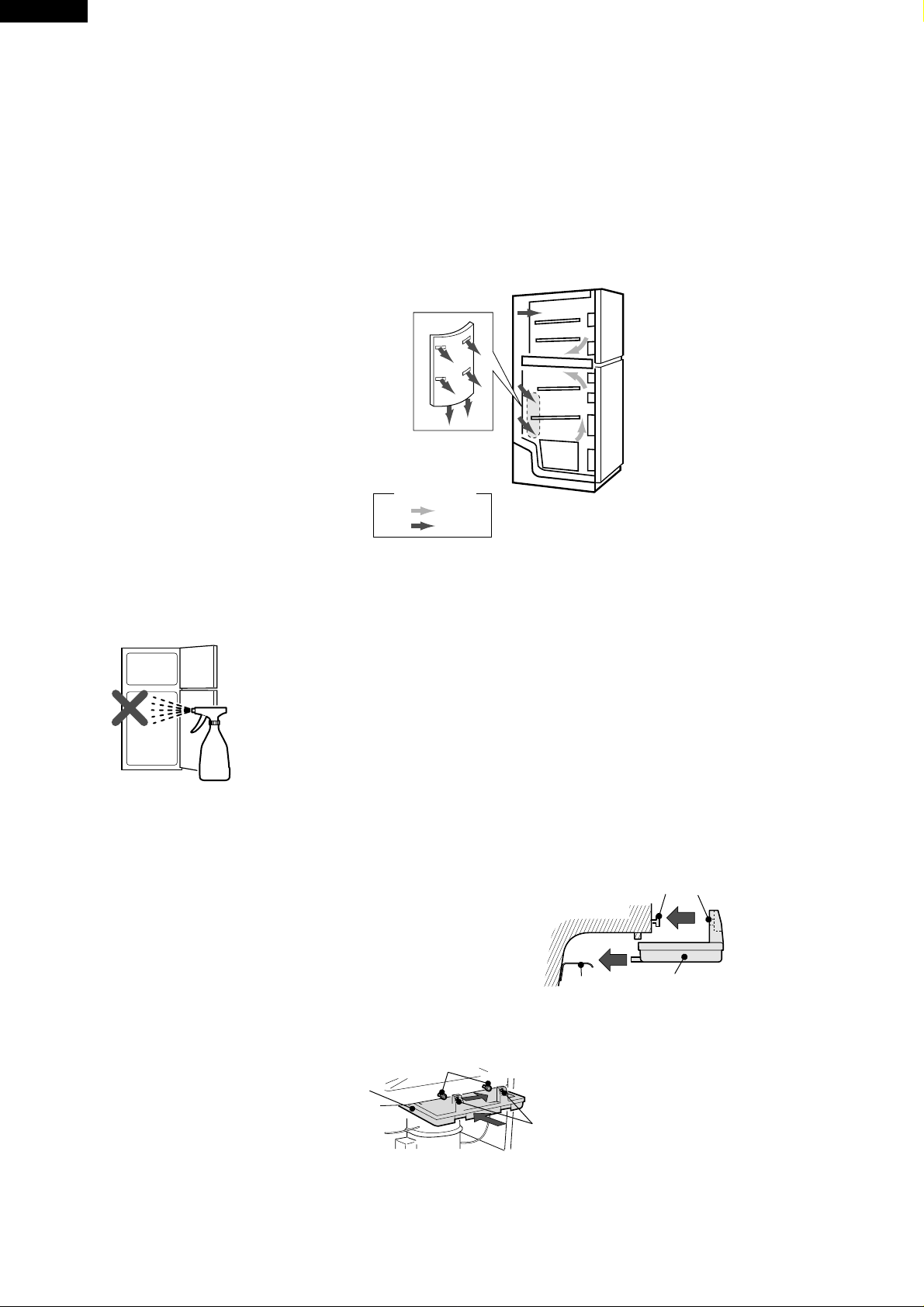
In case of following troubles, the cause is not related with the failure of refrigerator.
Please mention the correct way to the customer for the use of refrigerator when the repairing.
1. Some foods freezed in the refrigerator compartment.
Do not place food directly in front of
cold air outlet.
This may lead to the food freezing.
cold air flow
IN
OUT
2. Some plastic parts were cracked or splitted.
Some household cleaning chemicals may affect the internal
food liner and plastic parts resulting in splitting or cracks
occurring.
When cleaning all plastic parts inside this refrigerator, only
use diluted dishwashing liquid(soapy water). Make sure that
all plastic parts are thoroughly rinsed with water after cleaning.
3. Water leaked on the floor.
Make sure the back end of Evaporating pan
rests securely on the rail.
Protrusions
Holes
Set Evaporating pan so that the two protrusions
on the machine come through its corresponding holes,
and move the pan to right.
Protrusions
Evaporating pan
2
Evaporating panRail
Holes
SJ-21P
SJ-D25P
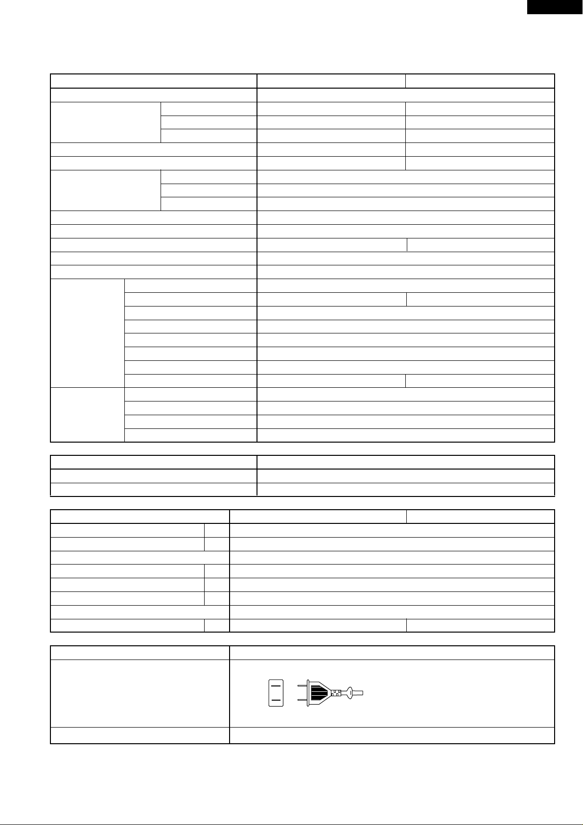
SPECIFICATIONS
Items SJ-21P SJ-D25P
Type 2-Door
Outer dimensions Height 1350mm 1510mm
(Including spacer) Width 545mm 545mm
Depth 585mm 585mm
Rated storage volume 190 liter F: 60 liter R: 130 liter 225 liter F: 60 liter R: 165 liter
Rated gross volume 210 liter F: 73 liter R: 137 liter 245 liter F: 73 liter R: 172 liter
Defrosting System Heater system
Start Automatic
Finish Automatic
Temperature control Automatic (Adjustable)
No-frost freezer Yes
Deodorizing system No Yes
Interior lamp 1
Evaporating pan 1
Refrigerator R tray S 1
Compartment R tray L - 1
Free set shelf 1
V tray 1
Vegetable case 1
Egg tray 1
Bottle pocket 2
R door pocket 1 2
Freezer F-partition tray 1
Compartment F tray 1
F door pocket 2
Ice cube maker Twin ice cube maker
COLOR
Items SJ-21P-GY,SJ-D25P-GY
Outside color Gray
Inside color White
RATING
Models SJ-21P SJ-D25P
Rated voltage (V~) 110
Rated frequency (Hz) 60
Climate class ST
Rated input (W) 100
Rated input of heating elements (W) 158
Defrosting input (W) 158
Refrigerant (Charging quantity) HFC-134a(85g)
Net weight (kg) 43 46
PLUG TYPE
Plug cord 2 pin
Plug type A-1
Destination mark F
3
SJ-21P
SJ-D25P
EXTERNAL DESCRIPTION
By Operation manual
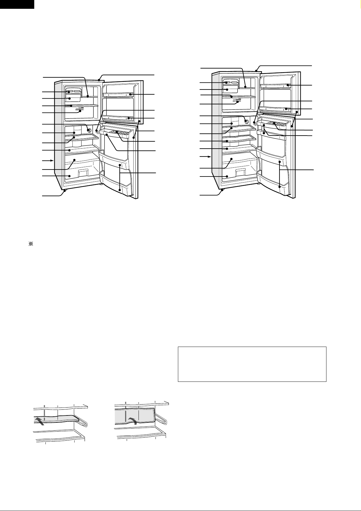
DESIGNATION OF VARIOUS PARTS
10
11
12
13
14
1
1
15
2
2
3
4
5
16
17
16
6
7
8
18
19
20
3
4
5
6
7
8
9
10
15
16
17
16
18
19
20
11
21
12
13
21
14
SJ-D25PSJ-21P
Fig. D-1
The names in parenthesis" [ ]" are the denominations used in the REPLACEMENT PARTS LIST.
1. Freezer shelf (Small) [F-partition tray]
2. Ice cube maker
3. Ice cube box [Ice storage box]
4. Freezer shelf (Large) [F tray]
5. Freezer temp. control knob
6. Refrigerator temp. control knob
7. Light [Lamp]
Replacing the lamp bulb
Replace lamp bulb with same type.
Base E12, MAX 10W
Make sure that the rated voltage and wattage of the
lamp bulb are correct when replacing (check the label
near the bulb).
8. Refrigerator shelf (Small) [R tray S]
9. Refrigerator shelf (Large) [R tray L]
10. Three position adjustable shelf [Free set shelf]
This shelf has three positions, it can be partly or fully
extended or be fully folded away simply by pushing
the shelf back then lifting it up.
15. Table top [Top table]
Do not place hot objects on the table top. The table
top may melt and deform. The table can resist
temperatures up to 100˚C.
16. Freezer pocket [F door pocket]
17. Light switch
18. Magnetic door seal [Door packing]
19. Egg holder [Egg tray]
20. Free pocket [R door pocket]
21. Bottle pocket
Deodorizing unit (Only for SJ-D25P)
A built-in unit which requires no manual operation
because it automatically starts operating when the
refrigerator is powered on.
11. Evaporating pan
12. Shelf [V tray]
13. Fruit and vegetable crisper [Vegetable case]
14. Adjustable foot [Adjustable leg]
4

CONSTRUCTIONS
SJ-21P
SJ-D25P
Mark: Cold air flow
Fan motor
Defrost thermostat
F-temp. control knob
Evaporator
Defrost heater
R thermostat
Defrost timer
Lamp
V tray
Vegetable case
Compressor
Fan motor
Defrost thermostat
F-temp. control knob
Evaporator
Defrost heater
R thermostat
Defrost timer
Lamp
V tray
Fig. D-2 (SJ-21P)
Mark: Cold air flow
Vegetable case
Compressor
Fig. D-3 (SJ-D25P)
5
SJ-21P
SJ-D25P
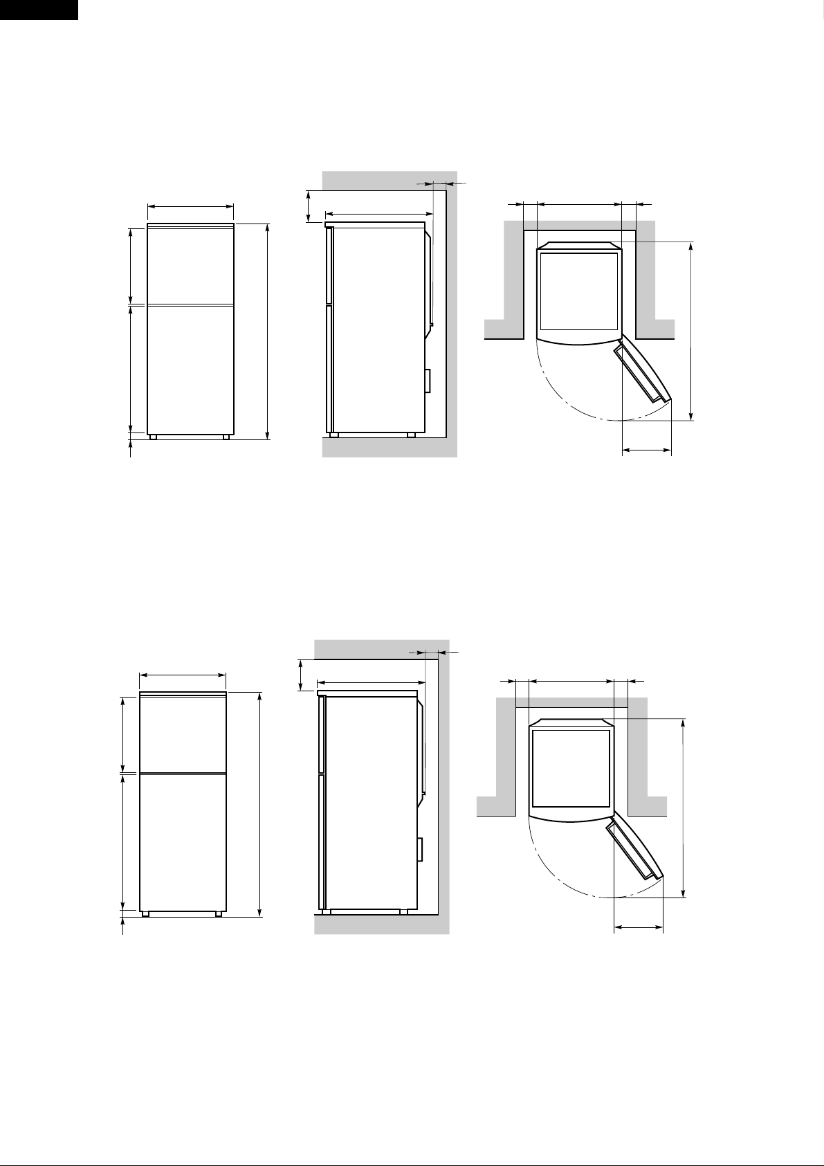
OUTER DIMENSIONS AND CLEARANCE
545
more than
90
DIMENSIONS
more than
60
585
more than
60
545
more than
60
33 799.5 481
545
1350
more than
90
Fig. E-1(SJ-21P)
more than
60
585
more than
60
545
1073
420
( Unit : mm )
more than
60
33 959.5 481
1510
1073
420
( Unit : mm )
Fig. E-2(SJ-D25P)
6
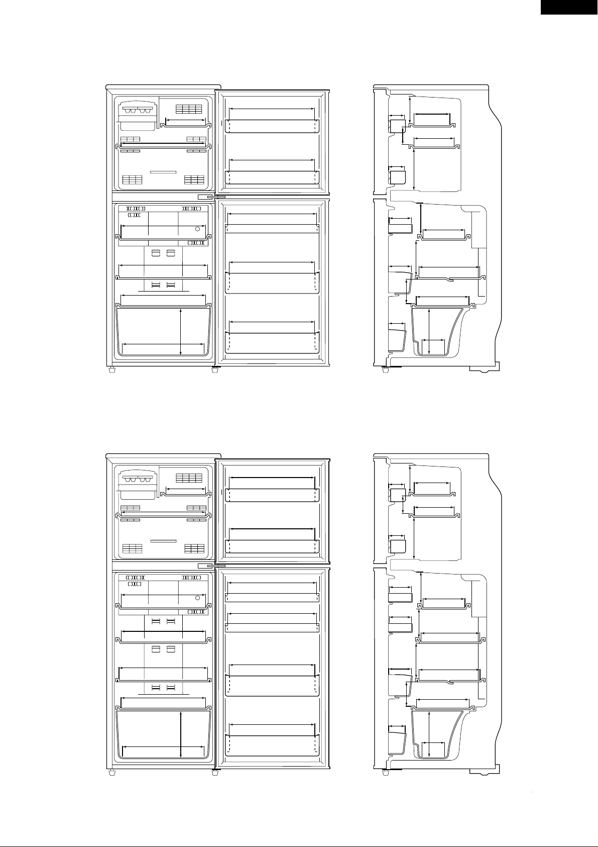
INNER DIMENSIONS
SJ-21P
SJ-D25P
389
390
391
414
402
207
220
379
379
407
384
384
Fig. E-3(SJ-21P)
76
76
108
124
84
70
110
134
207
152
141
182
189
198
291
237
220
129
(Unit : mm)
389
390
391
391
414
402
207
220
379
379
407
407
384
384
76
76
108
108
124
84
70
110
134
207
158
141
134
182
189
198
267
291
237
220
129
Fig. E-4(SJ-D25P)
7
(Unit : mm)
SJ-21P
SJ-D25P
LIST OF ELECTRICAL PARTS
ITEMS TYPE NAME RATING SPECIFICATIONS
Defrost thermostat S101 125V,15A Open : 10˚C , Close : 1˚C
Timer TMDFX04FB2 100-127V Integration type
50/ 60Hz Cycle time : 10h (60Hz)
Delay time : 4m (60Hz)
Thermo. fuse (defrost) SF70E 250V,10A Cut off temperature : 70˚C
Door switch 100424NC 250V,0.25A 2 terminals type push-button
Fan motor 3R00057B 110V,60Hz —
Lamp — 110V,10W E-12
Lamp socket — 250V,1A E-12 (Hard plastic body type)
R-thermostat MM1-8071F — ON : 3.5˚C , OFF : 0.5˚C
Defrost heater — 100-110V 78.8Ω without deodorizer (SJ-21P)
78.8Ω with deodorizer (SJ-D25P)
Compressor EMI50HNP 115V Main : 3.85Ω
60Hz Aux : 7.70Ω
Cooling capacity 151W
Terminal shape
Common
Aux. coil
Main coil
1
Starting relay P600E ——
Protector 4TM319RFBYY ——
Compensating thermostat
S101 125V,15A Open : 25˚C , Close : 17˚C
Compartment heater — 110V, 4.8W 2500Ω
The black dot ( ) indicates non-replacement parts or part which is not replaceable itself.
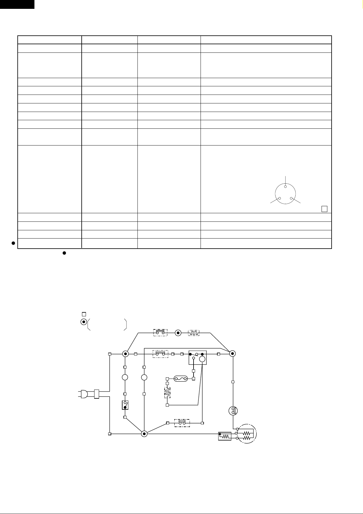
WIRING DIAGRAM
Be sure to replace the electrical parts with specified ones for maintaining the safety and performance of the set.
CONNECTOR
CONNECTED IN
TERMINAL BOX
2PIN AC
Plug /
Cord
(Br)
(Br)
Lamp
(S-B)
L
Door
Switch
Compensating
Thermo.
R-Thermo.
Fan Motor
FM
(W)
(O)
(B)
Compartment
(O)
Heater
34
(R)
2
Thermo.
Fuse
(Bk)
Defrost
Heater
Defrost
Thermo.
TM
Defrost
Timer
1
(Y)(Y)
(Bk)
(G)
Protector
(Overload relay)
C
B : BLUE
G : GRAY
(B)
Bk : BLACK
P : PINK
Br : BROWN
S-B : SKY-BLUE
Figure W-1. Wiring Diagram
8
Starting relay
(P.T.C relay)
O: ORANGE
W: WHITE
M
A
Compressor
R: RED
Y: YELLOW
SJ-21P
SJ-D25P
G
: GRAY
: BROWN
Br
: ORANGE
O
: RED
R
: PINK
P
: BLUE
B
: BLACK
Bk
: SKY-BLUE
S-B
: WHITE
W
: YELLOW
Y
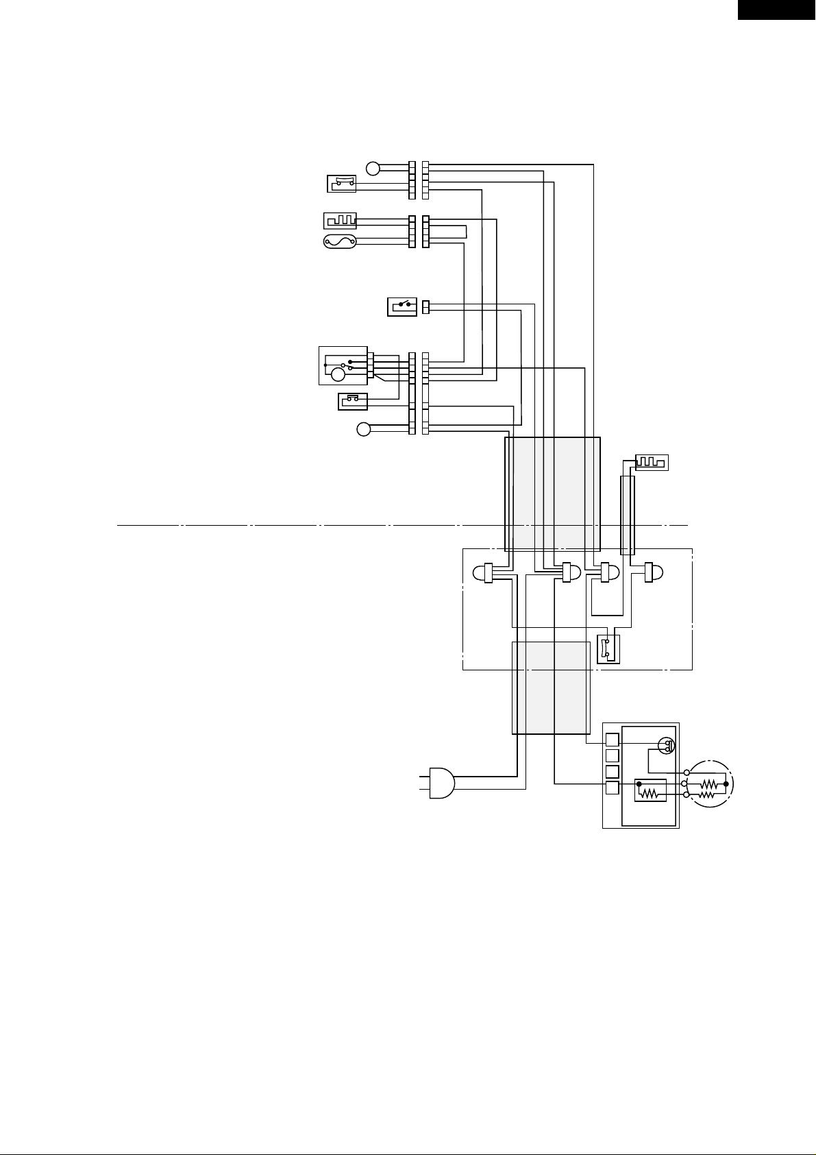
DEFROST
THERMOSTAT
DEFROST
HEATER
THERMO.
FUSE
DEFROST
TIMER
R-THERMOSTAT
FAN MOTOR
FM
DOOR SWITCH
TM
L
LAMP
(G-1)
1
1
(B-1)
2
2
(B-3)
3
3
4
4
(Y-1)
5
5
66
(Y-2)
1
1
(W-1)
2
2
(W-1)
3
3
4
4
(BK-1)
(B-2)
1
(SB-1)
2
(R-1)
3
2
4
1
1
1
(BK-1)
2
2
(G-2)
3
3
(Y-1)
4
4
(Y-2)
5
5
(BR-1)
6
6
(SB-1)
7
7
(BR-2)
8
8
COMPARTMENT HEATER
(Br)
Fig. W-2. Electric Accessories Layout
(B) (G) (O)
COMPENSATING
THERMO.
PROTECTOR
1
L
E
N
STARTING
RELAY
COMPRESSOR
C
M
A
9
 Loading...