

Page 1

SERVICE MANUAL
CODE: 00ZSFS15SM//E
MODEL SF-S15
CONTENTS
[ 1 ] BASIC SPECIFICATIONS . . . . . . . . . . . . . . . . . . . . . . . . . . . . . . . . . . . . . .1
[ 2 ] UNPACKING AND INSTALLATION . . . . . . . . . . . . . . . . . . . . . . . . . . . . . .1
[ 3 ] COMPONENT IDENTIFICATION . . . . . . . . . . . . . . . . . . . . . . . . . . . . . . . .4
[ 4 ] OPERATIONAL DESCRIPTIONS . . . . . . . . . . . . . . . . . . . . . . . . . . . . . . . .5
[ 5 ] DISASEEMBLY, ASSEMBLY AND ADJUSTMENT . . . . . . . . . . . . . . . . . .9
[ 6 ] ELECTRIC CIRCUITS . . . . . . . . . . . . . . . . . . . . . . . . . . . . . . . . . . . . . . . .19
[ 7 ] ELECTRICAL COMPONENTS . . . . . . . . . . . . . . . . . . . . . . . . . . . . . . . . .25
[ 8 ] CIRCUIT DIAGRAM . . . . . . . . . . . . . . . . . . . . . . . . . . . . . . . . . . . . . . . . .27
[ 9 ] PWB LAYOUT . . . . . . . . . . . . . . . . . . . . . . . . . . . . . . . . . . . . . . . . . . . . . .28
PARTS GUIDE
Parts marked with "! " is important for maintaining the safety of the set. Be sure to replace these parts with specified ones for
maintaining the safety and performance of the set.
This document has been published to be used for
SHARP CORPORATION
after sales service only.
The contents are subject to change without notice.
Page 2
[1] BASIC SPECIFICATIONS
Name: SF-S15
Type: Floor type
Paper distribution: Gate switching distribution
No. of bins: 20
No. of sheets accommodated: 50 sheets/bin, except for the top bin
(non-sort tray) which accommodates
100 sheets.
• When sorting: 50 sheets
• When grouping: 30 sheets
Paper size
• Non-sorting: A3~A6/11″×17″~8-1/2″×5-1/2″
• Sorting, grouping: A3~A5/11″×17″~8-1/2″×5-1/2″
[2] UNP ACKING AND INSTALLATION
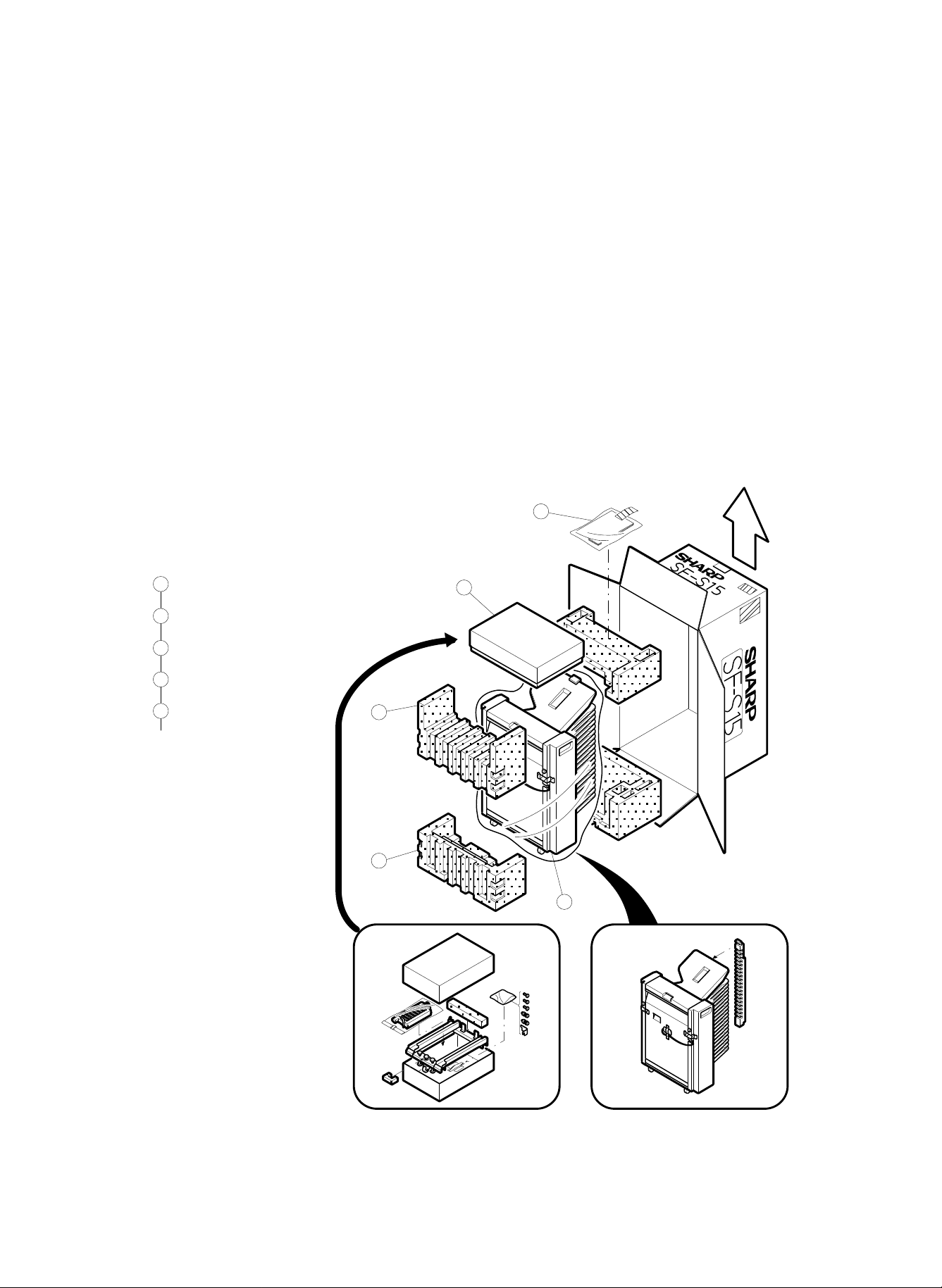
1. Unpacking
• Unpack following the flow chart shown below.
Processing capacity: Equivalent to 25 to 60 sheets/min.
Paper transfer: Center reference
Storage: Face up
Paper weight
• Non-sorting: 52~128 g/m
• Sorting, grouping: 56~80 g/m
Power supply: Supplied from copier
Dimensions: 550 (W) x 519 (D) x 924 (H)mm
Weight: 20.3 kg (44.6 pounds)
5
2
(14-31 1bs)
2
(15-21 1bs)
Accessories
1
2
Packing DR
3
Packing DL
4
Sorter
5
Instruction manual set
Subsequent steps omitted.
1
2
3
4
– 1 –
Page 3

2. Installat ion
• Check the contents of package for specified quantities of the fol-
lowing items.
Accessories
3. Remove the front panel of the sorter.
Loosen the four screws which clamp the front panel of the sorter, and
remove the front panel.
• Install the sorter in the following procedure, after disconnecting the
power cord of the copier.
1. Mount the linkage paper guide.
Mount the linkage paper guide by hooking its two claws in the paper
outlet of the copier as shown below.
2. Install the sorter mount base on the desk.
Cut two notches into the left panel of the desk. Screw two clamp
screws of the sorter mount base into the desk. Hook the sorter mount
base on the two clamp screws A as shown in the figure.
Also attach the sorter clamp fixture on the sorter mount base and
clamp it with a clamp screw B.
4. Mount the sorter on the sorter mount base.
Lift the sorter using the handles, and place the sorter on the mounting
base with the rollers riding along the guide rails. Slide the sorter
gently to the end. Be sure the roller grooves of the sorter are all riding
on the guide rails as shown in the detail drawing below.
– 2 –
Page 4

5. Remove the rear panel of the copier and cut a
notch in the left panel.
Unscrew four clamp screws of the copier’s rear panel and remove the
rear panel. Then cut a notch in the left panel.
7. Replace the rear panel.
Install the rear panel removed in step 5 to its place, and fasten it with
four clamp screws.
8. Install the front panel of the sorter.
Install the front panel removed in step 3 to its place, and fasten it with
four clamp screws.
6. Connect the sorter connector.
Temporarily fix one of the two bracket clamp screws, which are
packed together with the sorter, into the threaded hole shown below.
Hook the lower notch of the bracket on the screw and clamp it on the
upper notch with another clamp screw. Tighten the temporarily fixed
clamp screw. Connect the 6P and 10P connectors of the sorter with
their counterparts of the copier. Fasten the lead wires with twist
bands.
9. Adjust the clearance between sorter and copier.
Press the sorter against the left panel of the copier gently. Adjust the
clearance between the sorter and the copier by turning the adjust
knobs provided on the sorter mount base, using as reference the gap
spacer which is attached on the back of the sorter.
After adjustment, remove the gap spacer.
– 3 –
Page 5
10. Set the option mode.
Discharge roller
Discharge roller
Top bin
Separator
claw
Idle roller
Feed roller
Discharge roller
Belt-driven roller
Sort bin
Eject roller
Suction belt
Belt-drive roller
Carrier rail
Sorter mount base
• Set the option mode by the keypad on the copier.
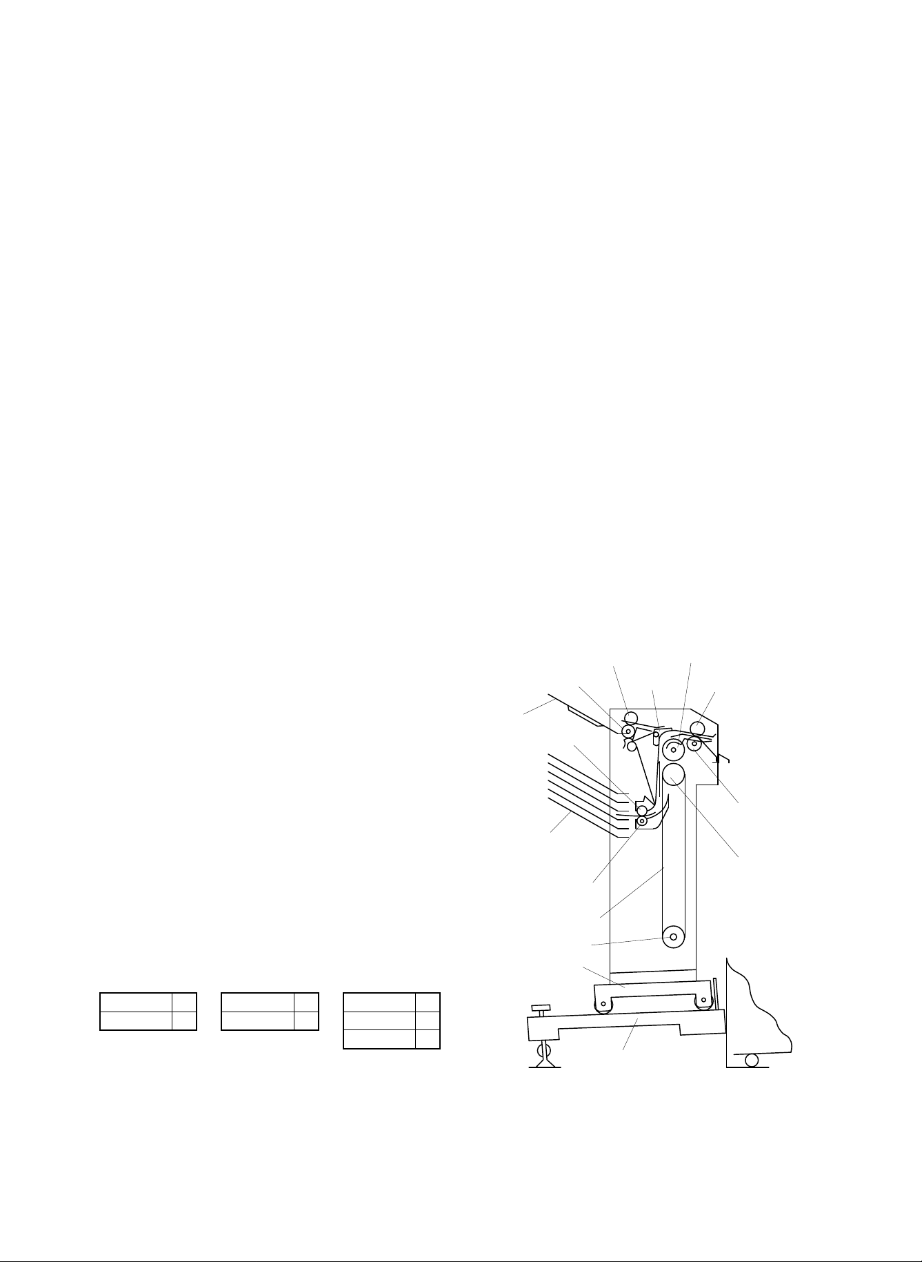
[3] CONPONENT IDENTIFICATION
1. External view
The above operation makes the current setting displayed.
• If SF-S15 only is to be set, the above operation should be followed
by the following key operation to set the mode.
• If mode setting is to be done in combination with other option, add
the values which correspond to the peripheral devices to be set
and enter the sum.
ex. To set SF-S15 and SF-A54, key in as follows since the value
corresponding to the peripherals to be set is 1 + 10 = 11.
2. Internal structure
SF-A54 1 SF-D20 4 SF-S14 10
SF-A14 1 SD-D21 4 SF-S15 10
SF-S52 10
– 4 –
Page 6
[4] OPERATIONAL DESCRIPTIONS
Timing belt
Pulley 23T
Pulley 23T
Paper feed
roller
Suction belt
Gear 23T
Gear 24T
High trail pulley
Transfer motor
Exit roller
Pulley 20T
Pulley 24T
Transfer belt
Separator claw
Indxer
Solenoid
Separator claw
Solenoid
Separator claw
Solenoid ON (When sorting or grouping)
Solenoid OFF (When non-sorting)
3. Driving mechanism of the transfer
section
1. Feeder section
• Copy paper discharged from the copier is fed along the paper
entry guide.
• A paper entry paper sensor is provided halfway along the paper
entry guide to detect the paper entry of paper.
• Feed rollers catch the paper to send it to the transfer section.
Feed roller
Copy paper
Paper
entry
sensor
Feed roller
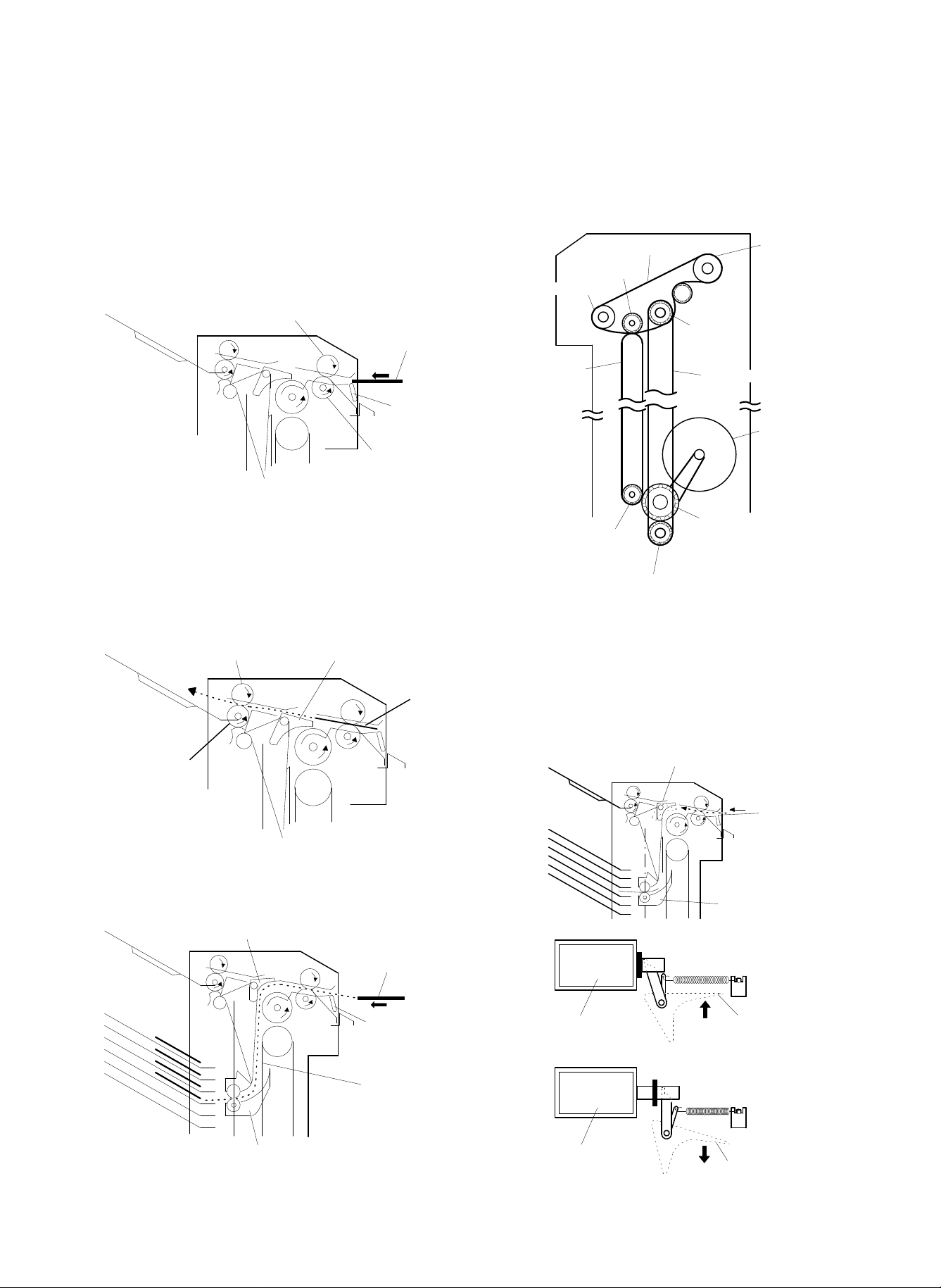
2. Transfer section
• The paper passage is switched by a separator claw between one
to the top bin (bin 1) and one to bins 2 through 20.
<Non-sorting operation>
The separator pawl rests on the lower position so that the paper
passes over the pawl to be transferr through the discharge rollers into
the non-sorting bin (top bin).
Discharge roller
Non-sorting bin
(Top bin)
Separator claw
(lowers upon solenoid OFF)
Paper
The feed rollers and the discharge rollers are driven by the transfer
motor via a high trail pulley, gear 24T, transfer belt, pulley 24T and
timing belt.
4. Separator section
• The solenoid-driven separator claw selects the paper passage be-
tween non-sorting and sorting paths.
• When the solenoid is OFF, the separator claw is in the lower
position so that the paper is discharged into the non- sorting bin.
• When the solenoid is ON, the separator claw is in the upper posi-
tion so that the paper is transferred by the suction belt and discharged into bins 2 through 20 by the indexer successively.
Discharge roller
<Sorting operation>
The separator pawl is in the lifted position so that the paper passes
under the pawl and is transferred by the suction belt to the indexer
which discharges the paper.
Indexer (Goes up or down by 1 bin after discharging paper.)
Separator claw (rises upon solenoid ON)
Paper (.. indicates
transfer passage.)
Suction belt
– 5 –
Page 7
5. Indexer sectio n
Drive belt
Discharge roller
Discharge roller
Indexer
Reel shaft
Reel
Reel spring
Riil film
6. Roller driving mechanism in the indexer
• Shifting operation of the indexer is driven by the shift motor.
• Indexing is performed by starting and stopping the shift motor
according to the ON/OFF of the Geneva. The sensor detects cuts
on the circumference of the Geneva gear while the gear rotates. A
half turn of the Geneva gear causes the indexer to make one shift.
Geneva sensor
Geneva gear
Wheel gear
Belt
Belt
Shift motor
Belt
• Rotation of the indexer is controlled from the copier.
Provided at top of the indexing mechanism are home position
sensor and upper limit sensor (over-run protection). Provided at
the bottom is the lower limit sensor.
• The discharge rollers in the indexer are driven by the transfer
motor via the high trail pulley, gear 24T and drive belt.
7. Reel film
• Reel film is stretched between the reel shaft and the indexer.
• The reel film is wound around the reel and is kept tight by a reel
spring.
Home position sensor
Upper limit sensor
Indexer
Indexer
Lower limit sensor
– 6 –
Page 8
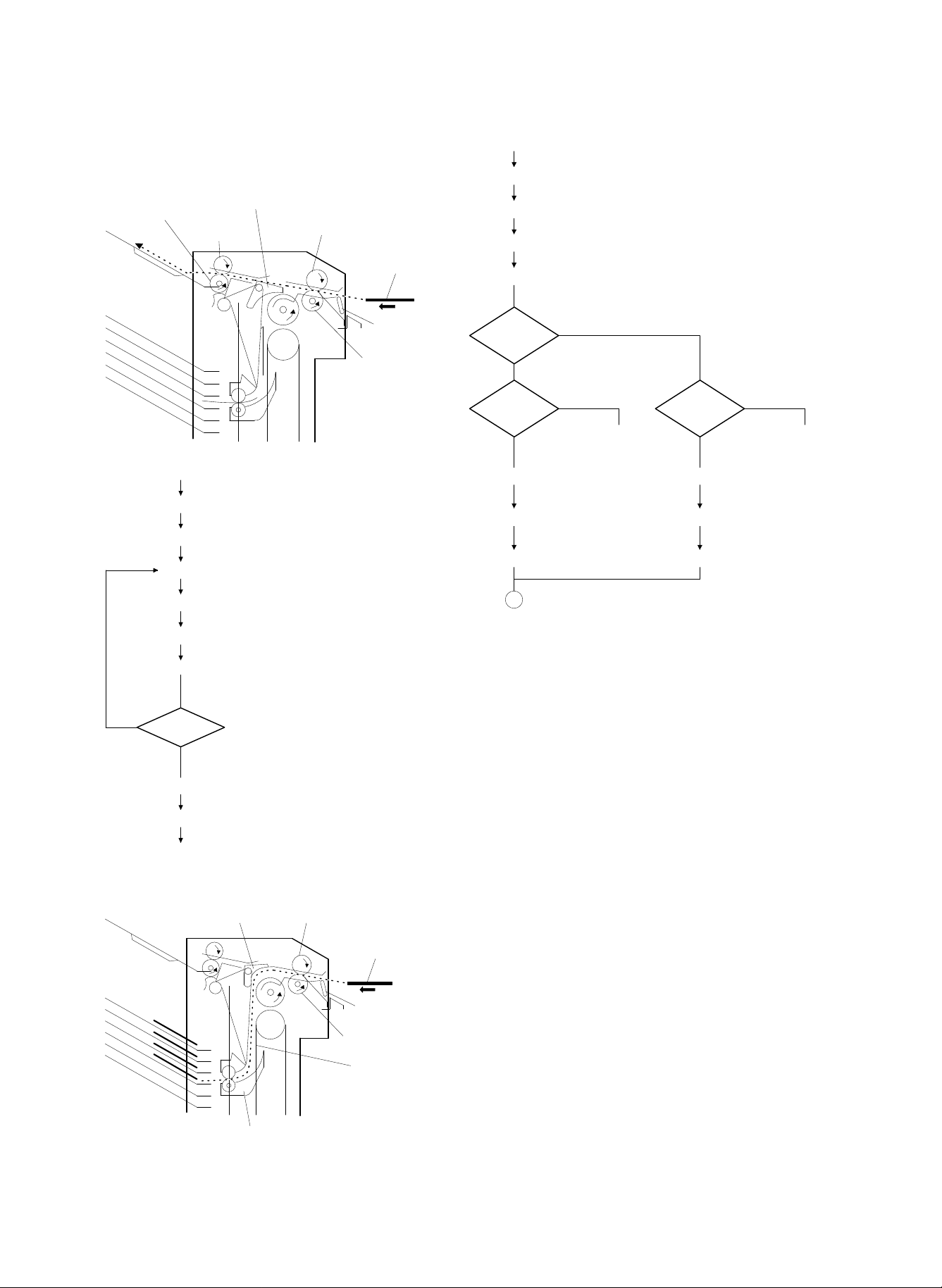
8. Operation seq uen ce
Start
STEP1
STEP2
STEP 3
STEP4
Print SW ON
Sorter fan motor ON
Sorter paper transfer motor ON
(discharge bin information, paper size information
included)
STEP18
STEP19
STEP20
1
Discharge
paper to bin 1?
Previous
paper passed
inlet sens or ?
Yes
Yes
No
No
Previous
paper passed
inlet sensor?
Yes
No
STEP 5
STEP 6
STEP 7
To STEP7 To STEP7
Solenoid ON timer
starts.
Solenoid ON timer
time-up
Solenoid ON
Solenoid OFF timer
starts.
Solenoid OFF timer
time-up
Solenoid OFF
<Non-sorting mode>
Discharge roller
Start
STEP1
STEP2
STEP3
STEP4
Separator claw
Discharge
roller
Feed roller
Feed roller
∗
··· ··· indicates transfer
passage.
Print SW ON
Sorter fan motor ON
Discharge signal received (discharge bin
information, paper size information included)
Sorter paper tr ansfer motor O N
Paper
Paper entry
sensor
Sorter inlet sensor ON
Sort er in let sensor OFF,
All load OFF timer starts.
All load OFF timer time-up
Fan motor, transfer motor OFF
Present
STEP5
STEP6
Next paper
STEP7
STEP8
End
<Sort/grouping mode>
⋅⋅⋅indicates paper transfer passage.
Separator claw
Indexer
Feed roller
Paper
Paper entry switch
Feed riller
Suction belt
– 7 –
Page 9
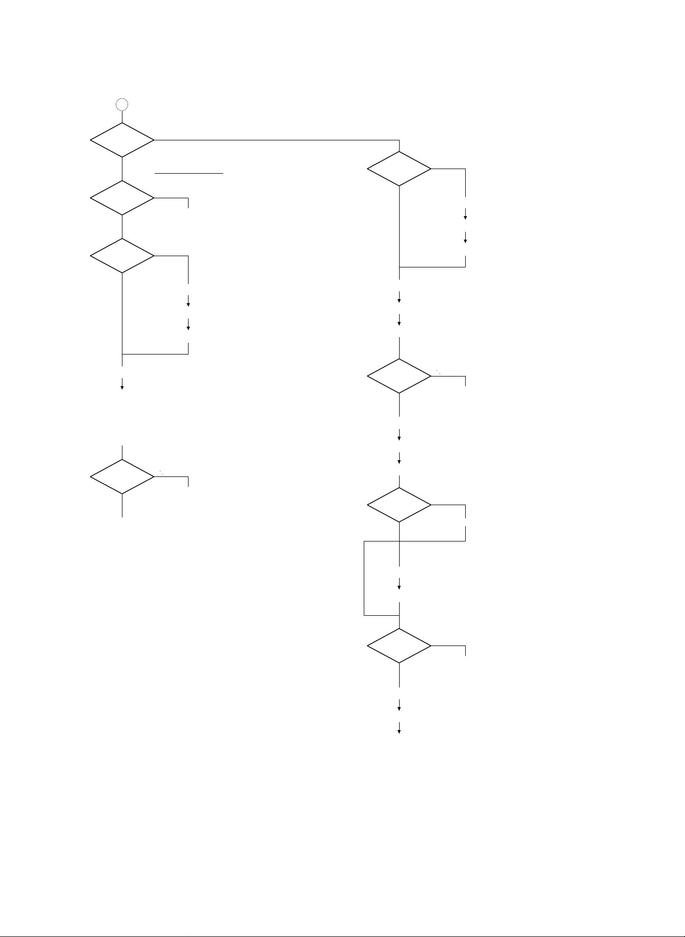
1
Discharge bin
information
> current bin position
< = C ur r e nt bin p o s it i o n
Discharge bin
information
= Current bin position
To STEP12
< Current bin position
Is previous paper
accommodated?
No
Yes
STEP24
STEP25
STEP26
STEP21
Indexer motor runs to lift.
STEP22
Indexer position sensor OFF
STEP23
Indexer position sensor ON
Previ ous paper dis c harge sens or OF F
Indexer ON timer starts.
Indexer ON timer tim e-up
Previous paper
accommodated
No
Yes
STEP27
Previous paper discharge
sensor O F F
STEP 8
STEP28
STEP29
Indexer motor runs to lift.
Indexer ON timer starts.
Indexer ON timer time-up
STEP9 Indexer position sensor OFF
STEP10 Indexer position sensor ON
Discharge bin
information
= Current bin position
To STEP8
= Current bin position
To ST EP11
To ST EP12
Indexer motor stops.
Sorter inlet se nsor ON
Discharge bin
information
To ST EP11
= Current bin position
To STEP12
= Current bin position
To ST EP13
Discharge paper
to bin 1?
No
Sorter inlet sensor OFF
Yes
All load OFF timer starts.
STEP14 Sorter discharge sensor ON
STEP15
Sorter discharge sensor OFF,
All load OFF timer st art s.
Next paper
No
STEP 9
STEP10
Present
To STEP3
All load OFF timer time-up
Sorter fan motor, Sorter paper transfer motor,
solenoid OFF
END
– 8 –
Page 10

[5] DISASSEMBLY, ASSEMBLY AND
Tray
Locking claw
Locking
claw
Front cover
Rear cover
Blower cover
Stepped screw
Blower stopper
Screw
Connector
Earth cable
Screw
Blower stopper
ADJUSTMENTS
Note: The sorter is equipped with casters. Ensure the sorter is not
allowed to roll away.
1. External parts
a. Loosen four screws of each of the front and rear covers, located
as indicated by the arrows in the figure below.
Front cover
Rear
cover
Rear
cover
Discharge side
<Precautions on assembly>
• Install the front and rear covers using their top as reference.
• When installing the rear cover, pay attention to the motor and
cables.
b. To remove the top cover, unscrew the two screws indicated by
arrows as shown below.
Feed side
2. Blower sectio n
(1) Blower unit
a. Remove the front and rear covers.
b. Unscrew the six screws shown in the figure below, and remove
the blower cover.
Reassemble
starting from top tray
Remove
starting from
bottom tray
c. Remove the tray, by pulling the tray toward you while pressing
down the lock pieces on both sides.
Note: The non-sorting tray (top bin) can be taken out and mounted
individually, but other trays must be removed in order starting
with the bottom tray, and mounted starting with the top.
c. Disconnect the connector and the earth cable.
d. Unscrew the two stepped screws which clamp the blower unit.
e. Unscrew four screws and remove the two blower stoppers.
– 9 –
Page 11

f. Remove the blower unit, with care not to hit the gear 23T with the
Screws
Screws
Support plate
E ring
Drive gear
Pin
Bearing
E ring
Suction belt roller
Bearing
Support plate
Screws
Fan motor
E ring
Sensor
cover
Screw
Screw
Screw
Magnetic
catches
E ring
Bearing
Screws
Bearing
E ring
Pin
G20T gear
E ring
Timing belt
First loosen this screw
angle.
Blower unit
Gear 23T
[Cautions on assembly]
• Assembly should be done in reverse order of disassembly.
• After setting the blower cover on the blower unit with six screws,
check as follows.
With the blower unit locked on the frame, check the dimension A in
figure below to see if A equals 2
smaller than 2mm, the blower belt may touch the indexer.
+0.5
mm. If this cle ara nce is
–0
(2) Disassembly of blower unit
a. Remove the blower unit from the frame in the procedure shown in
2.(1), a~f.
b. Remove the fan motor by removing cable bands, connectors and
three screws.
c. Unscrew six screws and remove two reinforcement plates.
d. Remove two blower belts.
e. Remove three E rings, drive gear 23T, parallel pin and two bear-
ings, to remove the blower belt roller.
Frame
Screw
Blower unit frame
Locking claw
A
+0.5
2
mm
-0
After adjustment, apply screw locking paint to the screw.
3. Dismount of feed roller
a. Remove the front and rear covers, to open the top cover.
b. Unscrew the clamp screw of the tension pulley and remove the
timing belt.
c. Unscrew four screws and remove the two magnet catches.
d. Remove the three E rings which fasten the feed roller, gear 24T,
parallel pin and two bearings.
e. Among three screws fastening the right and left, each, of each of
the upper and lower paper entry guides, unscrew two and loosen
one.
– 10 –
Page 12

f. Lower the lower paper entry guide in the direction indicated by
Remove screw
Solenoid
Top cover
Non-sort tray
E ring
Parallel pin
E ring
Timing belt
Bearing
Discharge roller
Bearing
E ring
Drive gear
A
2±0.3mm
Top guide
Separator claw
Guide roller
Solenoid
E ring
Within 8.0mm
Rubber washer
arrow in figure, lift the upper paper entry guide, and take out the
feed roller from the frame.
Note: Exercise care when pulling out the feed roller so as not to
damage the paper entry switch.
Paper entry switch
Upper entry
guide
Lower entry
guide
4. Dismounting of discharge roller
a. Remove the front and rear covers, to open the top cover.
b. Unscrew the clamp screw of the tension pulley and remove the
timing belt.
c. Remove the non-sorting tray.
d. Unscrew two screws and remove the solenoid.
e. Remove the three E rings, two bearings, parallel pin and the drive
gear.
Note: Be careful not to lose the parallel pin.
f. Remove the discharge roller.
Paper entry rollers
[Cautions on assembly]
• When setting the magnet catch for the clamping of the top cover,
clamp it with two screws while pressing the bend-up of the top
guide against the paper entry guide. Apply screw locking agent to
the screws after the adjustment described below.
<Adjustment>
1 Clearance between the bend-up and the paper entry guide
must be within 0.5mm when attracted by the magnet.
2 When the top cover is released at a position where its front
edge is 5mm high, it must be attracted by the magnet.
Top cover
Entry guide
GAP within 0.5mm
<Cautions on assembly>
• When setting the solenoid, exercise the following caution.
1 The solenoid must be set so that when it is pulling the clear-
ance between the separator claw and the guide roller is
2±0.3mm. The stroke of solenoid actuation should be within
8.0mm.
Note: When measuring the solenoid stroke, press the plunger in the
direction of arrow to remove play.
– 11 –
Page 13

2 After adjustment, apply screw locking paint to the two screws
Reel film
Transfer timing belt
Drive
timing belt
Slide
washer
Screw
Screw
Indexer
gear plate
Indexer
Screw
AB
Indexer
Fixed
screws
Loosen
screws
to adjust
Frame slit for bin fixing plate
which clamp the solenoid.
• When setting the timing belt and clamping the tension pulley parts,
check the following.
Loosen the W sems and check the tension pulley assembly to see
if it moves up and down smoothly. Then tighten the W sems to
clamp the tension pulley assembly.
This is because loosening of the W sems makes the tension spring
pull the tension pulley assembly upward resulting in proper tension
in the timing belt.
W sems
Tension spring
Timing belt
Tension pulley assembly
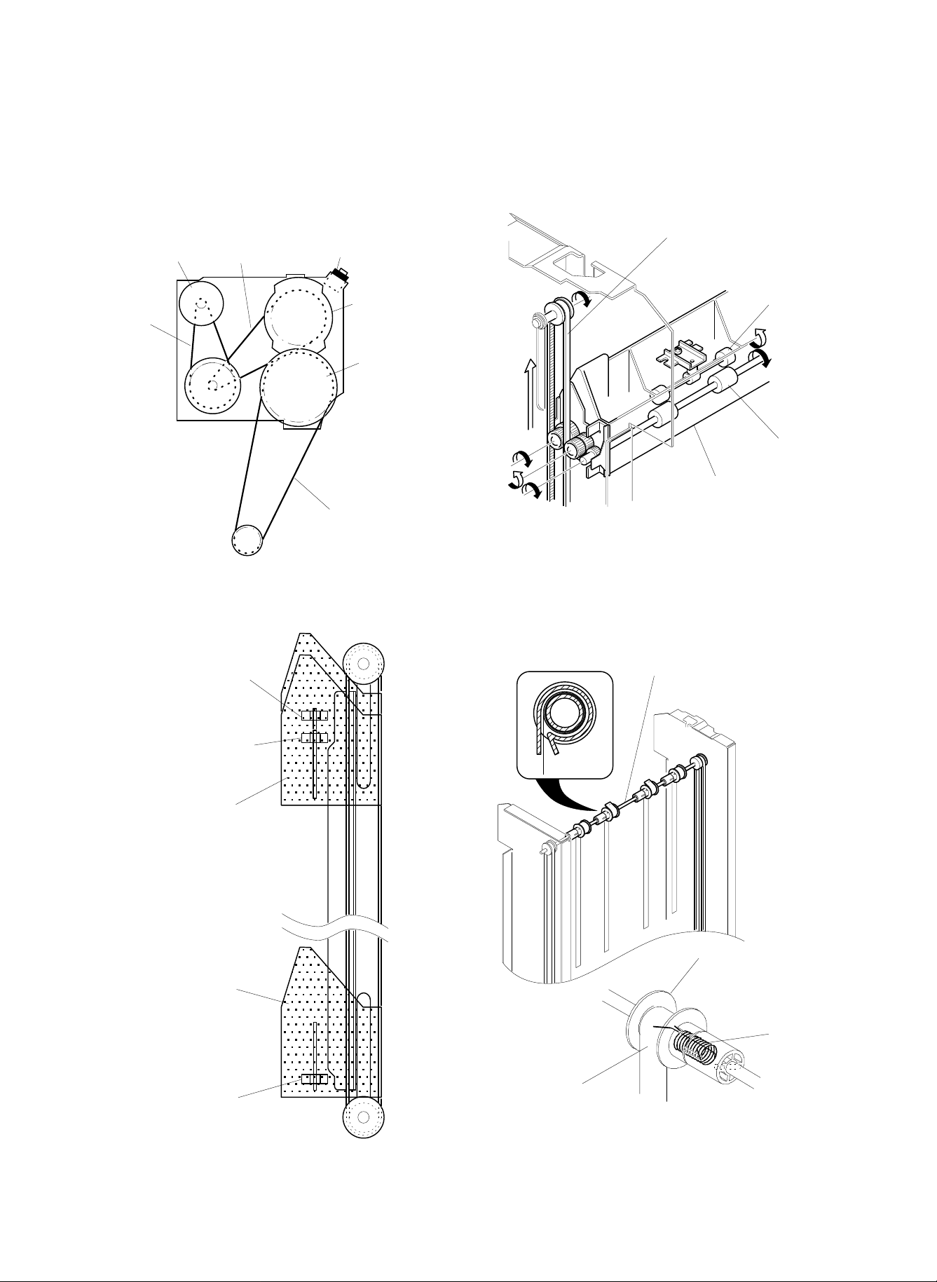
5. Dismounting the indexer
a. Remove the front and rear covers.
b. Remove the blower unit from the frame in the procedure de-
scribed in 2 (1), a~f.
c. Lower the indexer to a position around bin 13 where access with a
screwdriver is obtained.
Note: The indexer can be moved up or down by turning the gear
of the indexer drive motor by hand.
Indexer drive
motor gear
e. Unscrew the screws and remove the indexer gear and the slide
washer.
f. Remove the transfer timing belt from the indexer gear.
g. Unscrew four screws and remove the indexer from the drive tim-
ing belt.
<Cautions on assembly>
• Assembly should be done in reverse order to the disassembly.
• Set the indexer on the drive timing belt with four screws, with
care to keep the indexer horizontal (within 0.5mm of accuracy).
(Measurement and adjustment)
1. Set the indexer on the drive timing belt with four screws.
2. Measure the distance between the bottom frame of the indexer and the slit of the bin mounting frame. Finely adjust
the vertical position by means of the two screws on the left
shown in the figure below, so that the errors of A and B fall
within 0.5mm. In this case, the dimensions should be measured with the indexer lifted upwards.
A = B = 13mm
d. Unscrew four screws and remove the four reel films.
Note: Disengage the reel films while holding the films tight. Let
the reel film wind up to a position where the spring force is
balanced, and then release the films.
– 12 –
• When setting the reel films, be sure that the inner two reel
films are hooked on the shafts of the separator claws.
Page 14

6. Indexer unit
Inner ribbons fit to
rollers on diverter
guide shaft
a. When taking out and setting the indexer unit, see the instructions
given in paragraph 5.
b. When disassembling or assembling the indexer unit, refer to the
figure below.
c. When replacing the anti-static brush, refer to the figure below.
Align anti-static
brush with
A
Align anti-static brush guide
A
Earthing plate
Anti-static brush
side view
– 13 –
Page 15

7. Transfer timing belt
Reel retainer
Reel film
Indexer
Reel film
Reel film (Stuck with
double sided tape)
Reel
a. Remove the rear cover.
b. Remove the timing belt.
c. Remove the timing belt and remove the transfer timing belt from
the indexer gear.
d. Remove the two E rings, gear, parallel pin and two screws, and
remove the pulley assembly (w/transfer timing belt).
e. Unscrew four screws and remove the four reel films from the
indexer.
Note: Even when only one reel film is to be replaced, remove all
four reel films as in order to perform the adjustment.
f. Remove four reel retainers.
Pulley assembly
Transfer timing belt
Side frame
A
Screw
E ring
Gear
E ring
Screw
Parallel pin
<Cautions on assembly>
• Adjust the tension of the transfer timing belt in the following proce-
dure.
1 Set the transfer timing belt on the upper and lower pulleys, and
set the upper pulley assembly on the side plate.
2 While pressing the part A of the pulley assembly against the
upper side of notch in the side plate, raise the pulley assembly
(w/transfer timing belt) and clamp it with two screws.
3 After adjustment, apply screw locking paint to the two screws.
8. Replacemen t of reel fil ms
a. Remove the front and rear covers.
b. Remove the blower unit.
c. Remove the discharge roller and discharge guide.
d. Lower the indexer to the bottom bin.
Note: The indexer can be moved by turning the gear of the in-
dexer drive motor by hand.
g. Stick the double-side adhesive tape part of the reel film to be
replaced on the reel.
h. Wind up only the double-side adhesive tape section for all the four
reel films.
i. Clamp the four reel films on the indexer with four screws.
Note 1: Be sure that the indexer is positioned at the bottom bin.
2: The inner two reel films must be fastened to the indexer
after hooking on the shafts of the separator claws.
– 14 –
Page 16

j. While sliding the reel adjust upper in the direction of arrow in the
Bearing
Spring
E ring
Drive
timing
belt
E ring
Bearing
Slit in frame
Drive shaft
Reel shaft
Spring
Bearing
E ring
Bearing
E ring
Pulley
E ring
Slit in frame
figure below, turn the reel shaft CCW 8.5 turns with a flat tip
screwdriver, then slide back the reel adjust upper and lock the
reel.
Note 1: Be sure never to turn the reel shaft more than 8.5 turns.
2: Be sure that the reel films are not damaged by any
nearby surface, while turning them.
Reel
Reel
shaft
Front frame
k. After setting the reel films on the reels, set the reel retainers.
l. The rest of the assembly operation should be done in the reverse
order of the disassembly.
Reel adjust upper
Reel film
Drive belt
9. Replacement of drive timing belt
a. Remove the front and rear covers.
b. Remove the blower unit.
c. Remove the discharge roller and the discharge guide.
d. Remove the indexer in the procedure of 5, c~g.
e. Lower the indexer belt holder of the drive timing belt to the bottom
position. The belt can be moved by turning the gear of the drive
motor by ha nd.
Reel shaft
f. Remove the two E rings, two tension spring and two bearings.
Then tilt the drive shaft along the front side slit and remove the
two drive timing belts.
Indexer belt holder
(Lower to the bottom.)
Drive shaft
h. Set the indexer belt holder on the belt to be replaced.
i. Set two drive timing belt on the drive shaft, and set the drive shaft
on the frame.
j. Set two drive timing belt on the reel shaft, and set the reel shaft on
the frame.
Note: Both indexer belt holders, right and left, of the two drive
timing belt must be set at the same height. Set the drive
timing belt in the following procedure.
1 Set the two timing belts on the reel shaft.
Lower the two indexer belt holders of the belt to the
2
bottom position (see the detail drawing).
Set the reel shaft (with the drive timing belt
3
attached) on the frame. Be careful not to allow the
holder to move while setting.
After setting, turn the gear of the drive motor to
4
raise the indexer belt holder, and measure the
difference in the height of both holders.
Yes
5 Is the height difference within 2mm?
No
Remove the reel shaft from the frame and repeat
6
the above operation starting with step 2.
Proceed to process K.
– 15 –
Page 17

Reel shaft
10. Dismounting the indexer drive motor
unit
a. Remove the rear cover.
b. Remove the transfer motor assembly.
c. Remove the connector, cable holder and three screws, and re-
move the indexer drive motor unit.
Drive shaft
Indexer belt
holder should
Indexer
belt holder
Drive
shaft
k. Set the indexer in the indexer belt holder. For the cautions on
installation and adjustment of the indexer, refer to <Cautions on
assembly> in [5], 5. Dismounting the indexer.
l. For the procedure of setting the reel films, refer to steps i through l
in [5] 8. Replacement of reel films.
m. The rest of the assembly operation should be done in reverse
order to the disassembly.
touch pulley
d. For the disassembly an assembly of the indexer drive motor unit,
refer to the figure.
<Cautions on assembly>
• Before setting the indexer drive motor unit on the frame, check the
belts of the unit to see if they are properly set on the pulleys.
– 16 –
Page 18

11. Discharge section
4
4
±
1m
m
Discharge
brush
Tray fixing
angle
Discharge brush
Home position sensor
Red connector
White connector
Upper limit sensor
Sensor protection angle
Screw
Screw
(1) Replacement of discharge brush
a. Remove the non-sorting tray and 19 sorting trays.
b. Unscrew four screws and remove the top cover.
Top cover
Screw
(2) Replacement of tray brush
a. Remove the front and rear covers.
b. Remove the non-sorting tray and the sorting trays.
c. Remove the tray brush.
d. Wipe the sticking surface of the tray brush to remove oil.
e. Stick the tray brush with reference to the figure below.
Note: When sticking the tray brush, the brush must be pressed
against the angle.
c. Unscrew two screws and replace the discharge brush.
Feed brush
Screw
12. Dismounting the home position sensor
and upper limit sensor
a. Remove the front cover.
b. Unscrew two screws and remove the sensor protection angle.
c. Unscrew one screw each to remove the home position sensor and
the upper limit sensor.
Screw
<Cautions on assembly>
• Identical sensors are used in home position detection and upper
limit detection. Never confuse the wires when connecting. Be sure
to connect the red connector to the home position sensor.
– 17 –
Page 19

13. Arrangement of wiring
a. Arrangement of the wiring for the paper entry switch section and
the discharge sensor section is as shown in the figure below.
Keep the wiring from contacting the roller.
Paper entry switch section
Harness
Discharge sensor section
Harness
14. Adjustment of discharge sensor
a. Set the elements of SW2 as 1: ON, 2:ON, 3:OFF, to open all
doors. Then turn on the power while pressing SW1.
b. Insert a sheet of tracing paper into the opening of bin 20.
c. Turn VR1 slowly to turn off the LED. Then VR1 again until LED1
lights, which completes the adjustment.
– 18 –
Page 20

[6] ELECTRICAL CIRCUITS
1. General
The electric circuit controls the motions of taking in the sheets of
paper discharged from the copier and distributing them into bins 1
through 20. These motions are controlled by the control signals delivered from the control circuit board based on the sensor outputs. The
circuit consists of the sensor input circuit which receives signals from
the sensors and sends them to the CPU and a circuit which drives the
motor and solenoid.
2. Block diagra m
DTR
DSR
TXD
RXD
RES
+5V
System
reset
Inverter
(IC9)
AND gate
(IC7)
+5V
+5V
(IC2)
(IC12)
IC1
+5V
PWB-S
PWB-L
ILLS
IPS
IULS
IHS
PES
UCSW
FCSW
SJS
+5V
+5V
+5V
+24V
+5V
+24V
+5V
PGND
AGND
(IC10)
(IC10 )
(IC10)
(IC10)
(IC10)
(IC10)
(IC10)
TrQ1
TrQ2
(IC9)
+24V
Driver
(IC4)
IM direction control circuit
+24V
+5V
Gate
(IC3)
Driver
(IC5)
SW1
SW2
PVF
GS
IM
+24V
PFM
Oscillator circuit
11.0592MHz
– 19 –
Page 21

3. Communication circuit
+5V
+5V
3
2
RA3
10K
RA2
47K
2
C6
1000000P
R1
7.5
IC8
13
4
C13
1000P
IC10
11
10
VR1
100
TD62305F
HD74HC14FP
T-PT7
CN5-1
CN5-2 PWB-S
SEN2+5V
CN5-3
CN5-4
SENGND
CN6-1
CN6-2 PWB-L
LED2+5V
SENVOL
PWB-S 1
PWB-S 2
PWB-S 3
PWB-S 4
PWB-L 1
PWB-L 2
PWB-S
PWB-L
13
PB4
1
IC1
10K
Ω
8
1
5
6
SEN2+5V
PWB-S (OUT )
SEN GND
SEN VOL
Comparator
Voltage
regulator circuit
Amplifier
Oscillator
Synchronization
sensing
circuit
Demodulator
circuit
5V
0V
tw
tp
tw 8µS
tp 130µS
+5V
98
423
1
C15
1000P
C14
1000P
IC10
HD74HC14FP
12
13 12
T-PT8
T-PT9
RA3
10K
CN4-1
CN4-2
CN4-3
CN4-4
CN4-5
+5V
ILLS
IPS
NC
GND
ILLS 3
ILLS 2
ILLS 1
IPS 3
IPS 2
IPS 1
ILLS
IPS
10
12
PB1
PB3
RA4
47K
IC10
HD74HC14FP
IC1
To IC7-12P
5. Sensor input circuit
+5V
RA5
CN1-1
CN1-2
CN1-3
CN1-4
CN1-5
CN1-6
CN1-7
CN1-8
CN1-9
CN1-10
CN1-11
DTR
GND
DSR
GND
TXD
GND
RXD
GND
RES
GND
JNT
4.7K
8
79
5
R13
100
R12
100
IC11
43
74LS06FP
R11
100
T-PT1
C23
100P
T-PT2
C22
100P
T-PT3
C21
0.1µ
IC9
98
HD74HC14FP
IC11
65
74LS06FP
IC9
11 10
HD74HC14FP
IC11
21
74LS06FP
26
20
23
18
17
INT1
PC3/INT2
PC6/CO0
PC1/RXD
PC0/TXD
This circuit communicates with the copier. Input and output signals
handled are as follows.
a. DTR CN1-1P
Input from the copier, meaning that the copier has the right of
transmission when IC1-20P is at L level (0V).
b. DSR CN1-3P
Output from the sorter, meaning that the sorter has the right of
transmission during a period since IC1-20P changes from L level
(0V) to H level (+5V) until it returns to L level, when IC1-23P is at
H level (+5V).
c. TXD CN1-5P
Input signal from the copier. Data is received when ICI-18P
changes from H level (+5V) to L level.
d. RXD CN1-7P
Output signal from the sorter. Data is transmitted when ICI- 17P
changes from H level (+5V) to L level.
e. RES CN1-9P
Reset signal from the copier. CPU (IC1) is reset when CN1-9P is
H level (+5V).
a. Paper discharge sensor
This circuit monitors the presence of paper on the indexer and determines whether paper is discharged onto the tray. CN6 is connected
to an infrared emitting LED and CN5 is connected to a light receptor
which receives the light from the LED.
Internal circuit of the light receptor is shown in the figure below.
The oscillator of the light receptor sends the output signal shown
below to the connector CN5-4P and SENVOL.
This signal is used to drive the LED to light in pulses, and the light is
sensed by the receptor where the synchronization monitor circuit incorporated in it determines whether the light pulses are synchronized
with the VOL outputs.
4. Reset circuit
IC9
+5V
R4
10K
C5
1000P
13 12
4
5
74HC08FP
HD74HC14FP
T-PT3
6
IC7
IC1
15
PB6
28
RST
+5V
R8
10K
25
NMI
Copier reset
D8
T-PT17
DSA010
2
+5V
RES
3
5
VCC
CK
T-PT5
4
T-PT6
GND
VS
*RES
VREF
7
C4
470P
8
1
CT
6
+
C1
1µ/50V
C7
0.1µ
IC6
MB3773FP
When the power is turned on, IC6-8P in the figure turns from L level
(0V) to H level (+5V) in about 100ms, to complete the resetting operation.
The reset circuit produces logical sum of the output from IC6-8P and
the reset signal from the copier. Reset is effected at the same time
the reset signal is received from the copier.
IC6 functions in such a manner, when the program stored in the
sorter starts to run upon completion of the resetting operation, if
IC6-3P receives clock signals at specified intervals (10ms) and the
CPU (IC1) and the program normally operate, the output of IC6-8P
goes to H level (+5V).
If a failure occurs such as panic run of the program to interrupt the
clock input, the system is reset within the monitor period of the watch
dog timer (about 100ms) determined by C1 (1µF), while the output of
IC6-8P remains at L level (0V). It, however, turns HIGH when a clock
input is applied within 100ms.
If no synchronization is observed, it means that paper is present
between the light emitter and the receptor.
Synchronization is determined to be lost when three pulses are not
synchronized.
When paper is present, output signal at H level (+5V) is fed to IC1011P, and inverted L level (0V) is fed to IC1-13P.
Light intensity is adjusted with VR1 to optimize for the receptor.
b. Indexer lower limit sensor (ILLS) circuit,
Indexer position sensor (IPS) circuit
1 The indexer lower limit sensor (ILLS) circuit is to sense when the
indexer overruns bin 20 to reach the lower limit, due to overrun of
the indexer motor (IM) or a panic run.
ILLS is a sensor of transparent type which comprises a LED and a
photo-diode, where light is normally transmitted. Normal output
level is H (+5V), while the photodiode gives L level (0V) output
when the indexer reaches the lower limit to interrupt the LED light.
– 20 –
Page 22

Consequently, L level output is fed to IC1-1P while inverted H
38
AN4
SJS
SJS 3
SJS 2
SJS 1
+5V
C25
1000P
R16
47K
R9
10K
CN2-1
CN2-2
CN2-3
+5V
SJS
GND
3
4
IC9
HD74HC14FP
T-PT13
IC1
1
16
2
15
3
14
IC8
IC8
IC8
TD62305F
x3
LED2
LED3
LED1
R7
R6
R5
220
x3
GL3PR8
x3
+5V
+5V
3,4
1,2
2678
RA7
10K
SW1
SKHHAM
1
2
3
4
8
7
6
5
SW2
DSS704
6
7
8
PA5
PA6
PA7
34
35
36
19
AN0
AN1
AN2
PC2
IC1
level (+5V) is fed to IC1- 10P.
2 The indexer position sensor (IPS) circuit senses the indexer posi-
tion to see if it is in a position appropriate for discharge.
Operation after sensing is similar to that of ILLS, and output is fed
to IC1-12P.
c. Indexer upper limit sensor (IULS) circuit
Indexer home sensor (IHS) circuit
Paper entrance sensor (PES) circuit
+5V
T-PT10
IULS
IHS
PES
IULS 3
IULS 2
IULS 1
IHS 3
IHS 2
IHS 1
PES 3
PES 2
PES 1
CN3-1
CN3-2
CN3-3
CN3-4
CN3-5
CN3-6
+5V
IULS
IHS
PES
NC
GND
1 The indexer upper limit sensor (IULS) circuit is to sense when the
indexer overruns the indexer home sensor (IHS) to reach the
upper limit, due to overrun of the indexer motor (IM) or a panic
run.
IULS is a sensor of transparent type which comprises a LED and
a photodiode, where light is normally transmitted. Normal output
level is H (+5V), while the photodiode gives L level (0V) output
when the indexer reaches the upper limit to interrupt the LED light.
Consequently, L level output is fed to IC10-3P while inverted H
level (+5V) is fed to IC1- 9P.
2 The indexer home sensor (IHS) circuit senses the indexer position
to see if it is in the discharge position of bin 2.
Operation after sensing is similar to that of IULS, and output is fed
to IC1-11P.
3 The paper entrance sensor (PES) circuit senses the paper dis-
charged from the PPC when it enters the entrance of the sorter.
Operation after sensing is similar to that of IULS, and output is fed
to IC1-14P.
RA3
10K
IC10
54
6
7
8
5
6
3
4
RA2
C16
47K
34
T-PT11
T-PT12
C12
C11
1000P x3
IC10
56
98
IC10
HD74HC14FP
x3
9
11
14
To IC7-9P
e. Sorter joint sensor (SJS) circuit
The sorter joint sensor (SJS) circuit checks to see if the sorter is
securely connected to the copier.
SJS is a sensor of transparent type which comprises a LED and a
photodiode, where light is normally transmitted. Normal output level is
IC1
PB0
PB2
PB5
H (+5V), while the photodiode gives L level (0V) output when the
sorter is connected to the copier causing the LED light to be interrupted. Consequently, L level output is fed to IC9-3P while inverted H
level (+5V) is fed to IC1-38P.
6. Power circuit
FUSE2
DC+24V
PG
DC+5V
SG
UL-TSC3^15A-N1
CN10-1
CN10-2
CN10-3
CN10-4
This circuit receives DC power from the copier. C3 and C2 are capacitors to filter out noise and smooth the +24V and +5V voltages, respectively. D7 and D3 are protective diodes which protect the ICs
from over voltage generated when connecting or disconnecting the
connector CN10.
C3
100µ/50V
C2
33µ/16V
TP3
TP4
TP1
TP2
+5V
+5V
D7
GP10-4003
PGND
ZD3
RD6^2FB
+
+
7. LED ligh tin g cir cu it
d. Upper cover switch (UCSW) circuit
Fan cover switch (FCSW) circuit
E
E
Q2
FA1L3N
C
+5V
R2
R3
10K
10K
IC1
40
AN6
39
AN5
UCSW
FCSW
CN11-3
CN11-2
CN11-1
UCSW
FCSW
DC24VDOR
+24V
ZD1
RD12MB2
ZD2
RD12MB2
T-PT15
T-PT16
Q1
FA1L3N
BC
B
DC +24V
These circuits monitor the upper cover and the fan cover while they
open or close. Two switches are connected in series, and turn on
when the cover is closed and turn off the cover is open. Closing of the
upper cover causes the switch contact to close, pulling up the base
voltage of Q1 to H level and pulling down the collector voltage of Q1
to L level (0V), feeding it to IC1-40P.
Operation of the fan cover switch (FCSW) is similar to the above.
Truth table for cover switch open/close
UCSW FCSW IC1-40P IC1-39P
Open Open H H
Close Open H H
Open Close H L
Close Close L L
General
The LED lighting circuit is used in test mode. LED1, LED2 and LED3
indicate the status of the sorter, and SW2 and SW1 are used in
setting the operation mode.
a. LED lighting circuit
The LED lighting circuit drives LED1 indicating the operating status of
the CPU (IC1), LED2 indicating the jam and alarm information and
LED3 indicating the open/closed status of the fan cover switch
(FCSW) and the upper cover switch (UCSW).
The LEDs are lighted by driving IC1-6P, 7P and 8P LOW. Status of
the LEDs show the status of the sorter as shown in the table below.
LED Blink ON OFF
CPU normally
1
running
2 Jamming Alarm issued Normally operating
3 ————— Door released Normally operating
CPU panic CPU panic
– 21 –
Page 23

b. DIP switch circuit
D5
GP10-4003
D6
GP10-4003
CN8-1
CN8-2
CN8-3
CN12-3
+24V
PVF
NC
+24V
GS
NC
NC
CN12-4
CN12-1
CN12-2
PVF 1
PVF 2
GS 1
GS 2
3
6
1
7
2
8
IN1
IN2
OUT1
OUT2
DRV
CLM
IC4
M5261L
R10
51
+5V
+5V
RA6
10K
43
PVF
GS
1
2
PA0
PA1
PGND
IC1
6K
10K
1K
5K
2K
DRIVE
CLM
OUT
GND
VCC
Active = Low
input IN
Unit:
Ω
The DIP switch circuit is used to set the operation mode when operating the sorter individually. Turning ON 1-4P of SW2 sets the signals
at IC1-19P, 34P, 35P and 36P to L level, respectively. The operation
modes are selected by the setting of the switch as shown below.
SW2-1 -2 -3 -4 Mode
1 OFF OFF OFF —
2 OFF OFF OFF —
Non-sorting paper-feed test
mode
Grouping paper-feed test
mode
*1
*2
3 ON OFF OFF — Sorting paper-feed test mode
4 ON ON OFF —
Discharge sensor adjust
mode
5 *2 *2 ON — Sorting no-paper test mode
*1 In the group paper presence test mode, the indexer shifts when
the SW1 (push switch) was pressed in selecting the paper presence test mode.
*2 The sorting no-paper test mode is selected only by setting SW2-3
to ON regardless of the setting of SW2-1 and -2.
8. Explanation of the operation (circuit)
1 Non-sorting paper-feed test mode
Set the DIP switch as 1:OFF, 2:OFF, 3:OFF, close all doors and turn
on the power while pressing SW1. Pressing SW1 in about one second causes the fan motor to turn on and the test mode to start.
In this test mode, when the inlet sensor detects paper, the transfer
motor turns on to discharge the paper into the non- sorting bin (bin 1).
About seven seconds after the tail edge of the last sheet passed the
inlet sensor, the transfer motor stops.
Pressing Sw1 after the transfer motor has stopped causes the fan
motor to stop to exit from the test mode. If SW1 is pressed again, the
fan motor turns on and test mode restarts.
Pressing SW1 after the transfer motor has stopped causes the fan
motor to stop to exit from the test mode. If SW1 is pressed again, the
fan motor turns on and test mode restarts.
4 Sorting no-paper test mode
Set the DIP switch as 3:OFF (1 and 2 may be in any position), close
all doors and turn on the power while pressing SW1. After initialization of the indexer, the transfer motor and the fan motor turn on and
the test mode starts. Pressing SW1 again ends the test mode.
5 Loaded operation mode (test with
commu nic a t ion with copie r )
The sorter is switched to loaded operation mode by a command from
the copier. Then a signal (22H 01H DATA1) which requests individual
loading operation sent from the master to the slave starts the individual loading operation.
Remedy for jam
(1) When paper jams, LED2 blinks and all loads are turned off. Open
the door and take out the jamming paper, and close the door.
LED2 will turn off indicating the jam is removed. Then pressing
SW1 brings the machine into the state similar to that after ending
the test mode.
Canceling alarm
(1) In case of alarm, LED2 blinks and all loads are turned off. The
alarm can be canceled by power ON reset.
9. Paper vacuum fan (PVF) circuit a. Paper
vacuum fan (PVF) circuit
Gate solenoid (GS) circuit
2 Grouping paper-feed test mode
Set the DIP switch as 1:OFF, 2:OFF, 3:OFF, close all doors and turn
on the power while pressing SW1. Pressing SW1 in about one second causes the fan motor to turn on and the test mode to start.
In this test mode, when the inlet sensor detects paper, the transfer
motor turns on to discharge the paper into the non- sorting bin (bin 1).
If SW1 is pressed when the transfer motor is ON after the transfer of
paper, the indexer is lowered by one level when the next sheet of
paper turns on the inlet sensor. Pressing SW1 twice (* ) causes the
If IC1-1P becomes L level (0V), IC4-7P becomes L level (0V) with GS
turning on, and the inlet gate opens to discharge paper into bin 2 and
the subsequent bins.
Circuit diagram
indexer to lower by two levels. Once the indexer reaches bin 20,
subsequent sheets are all transferred into bin 20 even if SW1 is
pressed.
About seven seconds after the tail edge of the last sheet passed the
discharge sensor of the sorter, the transfer motor stops.
Pressing SW1 after the transfer motor has stopped causes the fan
motor to stop to exit from the test mode. If SW1 is pressed again, the
fan motor turns on and test mode restarts.
3 Sorting paper-feed test mode
Set the DIP switch as 1:ON, 2:OFF, 3:OFF, close all doors and turn
on the power while pressing SW1. Pressing SW1 in about one second causes the fan motor to turn on and the test mode to start.
In this test mode, when the inlet sensor detects paper, the transfer
motor turns on to transfer the paper. Then every time the next paper
activates the inlet sensor, the indexer moves to the next bin. Upon
completion of paper transfer into bin 1 or 20, the indexer reverses its
moving direction.
About seven seconds after the tail edge of the last sheet passed the
– 22 –
discharge sensor of the sorter, the transfer motor stops.
Output-function
Input Output
L L (ON)
H H (OFF)
Page 24

10. Indexer (IM) circuit
IM
+24V
6P
2P
IC5
ON
OFF
ON
OFF
8P
4P
9, 5P
7, 3P
IM
+24V
6P
2P
IC5
ON
OFFON
OFF
8P
4P
9, 5P
7, 3P
20K x210000P x2
R19
R18
2
A
4
B
6
C
8
D
R20
R22
10K x2
R21
680
C30
100000P
C32
+5V
R17
680
C31
100000 P
PA2
PA3
PC4/TO
+5V
RA7
10K
12
43
3
13
4
10
74HC08FP
21
9
IC7
IC7
3
CUR
5
11
MODE1
7
MODE2
8
9
PWM
LSI-N9101MTD
IC3
IULS (Upper limit signal)
ILLS (Lower limit signal)
This circuit drives the indexer motor CW or CCW and move the
indexer up or down to discharge paper into bins 2 through 20.
GP10-400 3 x4
FUSE1
6
B
8
B
IC5
MP4005
2
B
4
B
D3D2
10
W
7
C
9
C
3
D4
C
PGND
5
C
W
1
PGND
UL-TSC1^25A-N1
CN9-1
IM
CN9-2
IM
C34
10000P
D1
+24V
IM 1
IM 2
IM
C33
a. CW rotation (down motion)
When IC1-3P output is H level (+5V) and IC1-4P is L level (0V),
IC3-2P and 6P are L level (0V) and 4P and 8P are H level (4P: +24V,
8P: +24V). Consequently, IC5-2P and 6P become L level (0V) and 4P
and 8P become H level (4P: +5V, 8P: +5V), causing the indexer
motor (IM) to rotate CW.
The motor can be turned ON/OFF with IC3-9P; stop at L level (0V),
rotatable at H level (+5V).
In case the lower limit sensor (ILLS) is activated due to software
panic or other reason, hardware protection is provided which stops
the motor using ILLS signal to prevent the motor from locking while
being kept ON.
When the motor is running CW, current flows as shown below.
Truth table for CW rotation
ILLS IM
H
(ON)
L
(OFF)
OFFLHLLHLHHLHHHLH
OFF
ONHHLHHLLHLHLHLH
IC1 IC3 input IC3 output IC5 input
213495724686824
L
HH
HL
L
LLHHHHHHHH
*If pins 5 and 7 of IC3 are both either H or L, brake mode is
effected driving all inputs of IC3 and IC5 to H level regardless of
the above table.
b. CCW rotation (moving up)
When IC1-3P output is L level (0V) and IC1-4P is H level (+5V),
IC3-2P and 6P are H level (2P: +5V, 6P: +24V) and 4P and 8P are L
level (0V). Consequently, IC5-2P and 6P become H level (2P: +5V,
6P: +24V), and 4P and 8P become L level (0V), causing the indexer
motor (IM) to rotate CCW.
The motor can be turned ON/OFF with IC3-9P similarly to the case of
CW rotation; stop at L level (0V), rotatable at H level (+5V).
In case the upper limit sensor (IULS) is activated due to software
panic or other reason, hardware protection is provided which stops
the motor using IULS signal to prevent the motor from locking while
being kept ON.
Current flows as shown below when running CCW.
– 23 –
Page 25

Truth table for CCW rotation
28 27 26 25 24 23 22 21 20 19 18 17 16 15
1 2 3 4 5 6 7 8 9 10 11 12 13 14
IC1
R17
C12
R3
C3
R2
C4
+
R4 R9
R10
C11 C10
R13
H1 H2 H3
R11
LD READY
GND
R16
R15
C9 C8
C5
R7
C6
R8
C2
D1, 2, 3
R1
D4, 5, 6
R12
R5
Q1
Q2
+
C13
R14
R6
C7
C1
+
VCC
+24V
P/S
ON/OFF
IULS IM
H
(ON)
L
(OFF)
ONHLHHLHHLHLHLHL
OFFL LHL LHHHHLHHHL
OFF
IC1 IC3 input IC3 output IC5 input
213495724686824
L
HH
LH
L
LLHHHHHHHH
11. Paper transfer motor (PFM) circuit
IC1
PA4
PB7
+5V
RA6
TD62305F
10K
IC8
2
5
16
5
HD74HC14FP
12
T-PT14
1
2
IC9
This circuit controls the transfer of paper discharged from the copier
into the sorter. PFM starts to run when IC1-5P output is made to L
level (0V). When the motor has stabilized at low speed running, PFM
delivers L level (0V) READY signal. This signal is fed to IC9-1P where
it is inverted to H level (+5V) and is fed to IC1-16P.
When the motor is locked, a protection circuit provided in the PFM
shuts off current flowing in the motor within 5 sec. This protective
action is reset by restoring IC1-5P from H level to L level.
R14
10K
C24
1000P
R15
10K
+5V
+24V
PGND
PFM+24V
ON/OFF
READY
READYGND
NC
CN7-1
CN7-2
CN7-3
CN7-4
CN7-5
PFM 1
PFM 3
PFM 4
PFM 2
PFM
Internal circuit of transfer motor
IC1-5P
output
L (0V)
PFM CN7-2P
input
IC1-16P
input
L H Rotating
L L Rotating under overload
H (+5V) H L Not rotating
Remark
– 24 –
Page 26

[7] ELECTRICAL COMPONENTS
PWB-L
UCSW
FCSW
IPS
SJS
PWB-S
ILLS
PES
IHS
IULS
1. Sensors, switches
Sensors, switches
Name Type Function Contact, output
PWB-L Light transmission sensor, emitter Emitter of discharge sensor, pulse lighting H level when detecting paper
PWB-S Light transmission sensor, receptor H level when paper passes discharge section
PES Light transmission sensor L level when paper is fed L level when detecting paper
IPS Light transmission sensor H level when discharge position of indexer is detected H level when detecting the position
IHS Light transmission sensor L level when home position of indexer is detected L level when detecting
IULS Light transmission sensor L level when indexer reaches upper limit L level when detecting
ILLS Light transmission sensor L level when indexer reaches lower limit L level when detecting
SJS Light transmission sensor L level when sorter is connected to copier L level when detecting
UCSW Micro SW Senses open/close of upper cover. ON when closed ON when closed
FCSW Micro SW Senses open/close of fan cover. ON when closed ON when closed
– 25 –
Page 27

2. Solenoids, motor s
GS
PVF
Solenoids
Name Type Function
GS Solenoid Paper is discharged to bin 2 and subsequent
Motor
Name Type Function
PFM Brushless motor Paper transfer motor
PVF Brushless motor Paper suction fan
IM DC motor Indexer drive motor
IM
PFM
bins upon gate solenoid, solenoid ON.
– 26 –
Page 28

6
5
4
3
2
1
3
2
1
IC7
74HC08FP
8
9
IC11
74LS06FP
710
IC8
TD62305F
+5V
1
VPP
*OE
A14
222726
53525150494847
PF6
10
12
11
13
6
11
6
5
IC9
HD74HC 14F P
20
*CE
A13
22321242510 9
PF5
IC2
A12
A11
A10A9A8
*OC
1
11
PF4
PF3
PF2
PF1
PF0
+5V
28 14 9 20 114 14 14
IC2 IC7 IC8 IC9 IC10 IC11 IC12 IC3
11121315161718
O0O1O2O3O4O5O6
A1A2A3A4A5A6A7
A0
8
7
6
2569121516
1Q
2Q
3Q4Q5Q6Q7Q
G
2D
1D3D4D5D6D7D8D
813141718
7
4
3
565758596061624644
55
PD0
PD1
PD2
PD3
PD4
10
GS
PVF
PVF 1
PVF 2
GS 1
GS 2
0.1µ x8
77 710
8
14 7
C27 C8 C17 C18 C19 C26 C29 C28
19
O7
M27C256B -15 F 1
5
4
3
19
8Q
IC12
74HC373F P
RD
PD5
PD6
PD7
ALE
876
5
SW2
123
4
1,2
+5V
78
SW1
6
3,4
2
RA7
10K
+5V
R7
R5
R6
220
x3
LED2
LED3
LED1
GL3PR8
x3
14
IC8
IC8
IC8
116
6
PA5
215
7
PA6
3
8
PA7
x3
TD62305F
343536
AN0
CN8-1
CN8-2
CN8-3
CN12-3
CN12-4
CN12-1
DSS704
+24V
PVFNC+24VGSNC
SKHHAM
D5
GP10-4003
1
CLM
28
DRV
3
R10
51
+5V
+5V
RA6
10K
43
19
1
AN1
AN2
PC2
CN12-2
NC
D6
GP10-4003
7
PGND
OUT1
OUT2
IC4
M5261L
IN2
IN1
6
RA7
+5V
2
PA0
PA1
IM
IM 1
IM 2
CN9-1
CN9-2
+24V
IM
IM
FUSE1
D2
D3
GP10-4003 x4
C33
R18
C32
20K x2 10000P x2
R19
+5V
10K
5
37
AN3
UL-TSC1^25A-N1
10
IC3
7
C
W
B
6
8
R20
R22
246
ABC
CUR
357
11
12
RA7
10K
9
B
MODE1
IC7
13
43
3
C34
10000P
D1
PGND
D4
3
5
C
C
C
PGND
1
W
B
B
IC5
MP4005
2
4
C31
+5V
10K x2
MODE2
8
9
PA2
100000P
R17
680
R21
680
C30
100000P
8
D
PWM
9
LSI-N9101M TD
IC7
10
4
RA1
10K
+5V
74HC08FP
212241
PA3
PC4/TO
+24V
+5V
+5V
934
PC5/CI
PFM
PFM 3
PFM 4
PFM 2
PFM 1
CN7-1
CN7-2
CN7-3
CN7-4
CN7-5
PFM+24V
ON/OFF
READY
READYGND
NC
PGND
R15
10K
R14
10K
C24
1000P
T-PT14
1
IC9
12
2
HD74HC 14F P
IC8
TD62305F
5
2
RA6
10K
RA1
10K
+5V
576
8
5
16
45
WR
PA4
AN7
PB7
245427
PC7/CO 1
29
PF7
MODE1
MODE0
EFGHI
INT1
PC3/INT2
262023
HD74HC14FP
IC9
98
T-PT1
C23
R13
8
+5V
79
5
RA5
4.7K
DTR
CN1-1
BCDEFGHI
A
[8] Circuit diagram
[8] CIRCUIT DIAGRAM
6
PC6/CO0
74LS06FP
IC9
IC11
65
T-PT2
100P
R12
100
100
GND
DSR
GND
CN1-2
CN1-3
CN1-4
PC1/RXD
18
10
HD74HC14FP
11
C22
TXD
GND
CN1-5
CN1-6
PC0/TXD
17
+5V
74LS06FP
IC9
IC11
13 12
21
T-PT3
100P
IC11
74LS06FP
43
RXD
GND
CN1-7
CN1-8
5
IC1
CMP730
AVDD
PB6
VAREF
42
43
C20
HD74HC14FP
C21
0.1µ
R11
100
RES
GND
CN1-9
CN1-10
RST
15
28
0.1µ
6
IC7
T-PT3
5
4
C5
R4
10K
+5V
T-PT5
381
D8
DSA010
T-PT17
JNT
CN1-11
6
CT
CK
2
*RES
RES
VCC
GND
5
4
+5V
C7
0.1µ
NMI
25
13
+5V
R8
10K
10
IC10
11
HD74HC14FP
74HC08FP
1000P
C1
+
7
VREF
VS
IC6
MB3773FP
T-PT7
2
1
RA3
10K
+5V
2
1µ/50V
3
C4
470P
T-PT6
SEN2+5V
CN5-1
µPD78C10AGQ
PB4
+5V
C13
1000P
RA2
47K
7.5
R1
C6
1000000P
SENGND
SENVOL
CN5-2 PWB-S
CN5-3
CN5-4
PB1
PB3
10
12
IC10
13 12
HD74HC14FP
VR1
100
12
IC10
T-PT9
4
13
IC8
RA3
+5V
LED2+5V
CN6-1
CN6-2 PWB-L
C15
T-PT8
2
4
TD62305F
C14
RA4
47K
3
1
10K
98
+5V
ILLS
IPSNCGND
CN4-1
CN4-2
CN4-3
CN4-4
PB0
PB2
PB5
91114
6
98
IC10
IC10
HD74HC14FP
HD74HC14FP
1000P
CN4-5
5
T-PT11
T-PT12
C12
IC10
1000P
34
T-PT10
864
RA3
10K
753
+5V
RA2
54
6
+5V
IULS
IHS
PESNCGND
CN3-1
CN3-2
CN3-3
CN3-4
CN3-5
AN6
AN5
AN4
X1
X2
Q2
E
ZD2
RD12MB2
UCSW
CN11-3
FA1L3N
C
B
FCSW
CN11-2
E
T-PT16
DC24VDOR
CN11-1
30
31
X1
HC49U
4
IC9
3
HD74HC14FP
C25
T-PT13
R16
47K
R9
10K
+5V
+5V
SJS
GND
CN2-1
CN2-2
CN2-3
403938
x3
R3
10K
+5V
R2
10K
1000P x3
C11
Q1
FA1L3N
BC
C16
47K
CN3-6
T-PT15
ZD1
RD12MB2
+24V
VSS
VASS
32
33
C9
33P
C10
33P
D7
GP10-4003
PGND
+5V
1000P
TP3
FUSE2
UL-TSC3^15A-N1
ZD3
RD6^2FB
+5V
TP2
TP4
TP1
+
+
C2
C3
100µ/50V
PG
DC+5V
DC+24V
CN10-3
CN10-1
CN10-2
CD
33µ/16V
SG
CN10-4
B
ILLS 3
ILLS 2
ILLS 1
IPS 3
IPS 2
IPS 1
IULS 3
IULS 2
IULS 1
IHS 3
IHS 2
IHS 1
PES 3
PES 2
PWB-S 1
PWB-S 2
PWB-S 3
PWB-S 4
PWB-L 1
PWB-L 2
ILLS
IPS
IULS
PWB-L
PWB-S
4
3
IHS
PES 1
UCSW
PES
2
SJS 3
SJS 2
SJS 1
FCSW
SJS
A
1
– 27 –
Page 29

[9] COMPONENT LAYOUT DRA WING
Control circuit board (Component side) 125V
Control circuit board (Component side) 250V
Control circuit board ( Solder side)
MEMO
MEMO
– 28 –
Page 30

A E
B
C
D
F
8
+5V
DTR
DSR
TXD
RXD
7
+5V
System
reset
6
PWB-S
PWB-L
ILLS
IPS
5
IULS
IHS
PES
4
UCSW
FCSW
SJS
RES
Inverter
+5V
+5V
+5V
+24V
+5V
(IC9)
IC1
AND gate
(IC7)
(IC10)
(IC10)
(IC10)
(IC10)
(IC10)
(IC10)
(IC10)
TrQ1
TrQ2
(IC9)
+5V
(IC12)
IM direction control circuit
+5V
Gate
(IC3)
(IC2)
+24V
Driver
(IC4)
+24V
Driver
(IC5)
+5V
SW1
SW2
PVF
GS
IM
8
7
6
5
4
+24V
3
+24V
+5V
PGND
AGND
PFM
2
Oscillator circuit
11.0592MHz
1
A E
B
C
D
F
3
2
1
– 29 –
 Loading...