

Page 1
SERVICE MANUAL
CODE: 00ZSF2030FM/E
No.1
MODEL SF-2030
MODEL SF-D20/21
MODEL SF-DM11
CONTENTS
[ 1 ] PRODUCT OUTLINE . . . . . . . . . . . . . . . . . . . . . . . . . . . . . . . . . . . . . . . 1-1
[ 2 ] PRODUCT SPECIFICATIONS . . . . . . . . . . . . . . . . . . . . . . . . . . . . . . . . 2-1
[ 3 ] OPTIONS SPECIFICATIONS . . . . . . . . . . . . . . . . . . . . . . . . . . . . . . . . 3-1
[ 4 ] COMPONENT IDENTIFICATION . . . . . . . . . . . . . . . . . . . . . . . . . . . . . . 4-1
[ 5 ] INSTALLATION . . . . . . . . . . . . . . . . . . . . . . . . . . . . . . . . . . . . . . . . . . . 5-1
[ 6 ] DISASSEMBLY AND REASSEMBLY . . . . . . . . . . . . . . . . . . . . . . . . . . 6-1
[ 7 ] ADJUSTMENTS . . . . . . . . . . . . . . . . . . . . . . . . . . . . . . . . . . . . . . . . . . . 7-1
[ 8 ] SIMULATION AND DIAGNOSTICS . . . . . . . . . . . . . . . . . . . . . . . . . . . . 8-1
[ 9 ] MAINTENANCE AND OTHERS . . . . . . . . . . . . . . . . . . . . . . . . . . . . . . . 9-1
SHARP CORPORATION
This document has been published to be used for
after sales service only.
The contents are subject to change without notice.
Page 2

CONTENTS
[ 1 ] PRODUCT OUTLINE . . . . . . . . . . . . . . . . . . . . . . . . . . . . . . . . . . . . . . . . . . . . . . . . . . . . . . . . . . . . . . . . . . . . . . . . 1-1
1. General description . . . . . . . . . . . . . . . . . . . . . . . . . . . . . . . . . . . . . . . . . . . . . . . . . . . . . . . . . . . . . . . . . . . . . . . . . . . . 1-1
2. Target users . . . . . . . . . . . . . . . . . . . . . . . . . . . . . . . . . . . . . . . . . . . . . . . . . . . . . . . . . . . . . . . . . . . . . . . . . . . . . . . . . . 1-1
3. Major featurs . . . . . . . . . . . . . . . . . . . . . . . . . . . . . . . . . . . . . . . . . . . . . . . . . . . . . . . . . . . . . . . . . . . . . . . . . . . . . . . . . 1-1
(1) Compact body . . . . . . . . . . . . . . . . . . . . . . . . . . . . . . . . . . . . . . . . . . . . . . . . . . . . . . . . . . . . . . . . . . . . . . . . . . . . 1-1
(2) Serviceability and f anctionality . . . . . . . . . . . . . . . . . . . . . . . . . . . . . . . . . . . . . . . . . . . . . . . . . . . . . . . . . . . . . . . 1-1
(3) High copy performance . . . . . . . . . . . . . . . . . . . . . . . . . . . . . . . . . . . . . . . . . . . . . . . . . . . . . . . . . . . . . . . . . . . . . 1-1
(4) Options . . . . . . . . . . . . . . . . . . . . . . . . . . . . . . . . . . . . . . . . . . . . . . . . . . . . . . . . . . . . . . . . . . . . . . . . . . . . . . . . . 1-1
4. System outline . . . . . . . . . . . . . . . . . . . . . . . . . . . . . . . . . . . . . . . . . . . . . . . . . . . . . . . . . . . . . . . . . . . . . . . . . . . . . . . . 1-1
[ 2 ] PRODUCT SPECIFICATIONS . . . . . . . . . . . . . . . . . . . . . . . . . . . . . . . . . . . . . . . . . . . . . . . . . . . . . . . . . . . . . . . 2 -1
1. Basic specification . . . . . . . . . . . . . . . . . . . . . . . . . . . . . . . . . . . . . . . . . . . . . . . . . . . . . . . . . . . . . . . . . . . . . . . . . . . . . 2-1
(1) Type . . . . . . . . . . . . . . . . . . . . . . . . . . . . . . . . . . . . . . . . . . . . . . . . . . . . . . . . . . . . . . . . . . . . . . . . . . . . . . . . . . . 2-1
(2) Copy method . . . . . . . . . . . . . . . . . . . . . . . . . . . . . . . . . . . . . . . . . . . . . . . . . . . . . . . . . . . . . . . . . . . . . . . . . . . . . 2-1
(3) Kinds of originals . . . . . . . . . . . . . . . . . . . . . . . . . . . . . . . . . . . . . . . . . . . . . . . . . . . . . . . . . . . . . . . . . . . . . . . . . . 2-1
(4) Copy speed . . . . . . . . . . . . . . . . . . . . . . . . . . . . . . . . . . . . . . . . . . . . . . . . . . . . . . . . . . . . . . . . . . . . . . . . . . . . . . 2-1
(5) First copy time . . . . . . . . . . . . . . . . . . . . . . . . . . . . . . . . . . . . . . . . . . . . . . . . . . . . . . . . . . . . . . . . . . . . . . . . . . . 2-1
(6) Warmup time . . . . . . . . . . . . . . . . . . . . . . . . . . . . . . . . . . . . . . . . . . . . . . . . . . . . . . . . . . . . . . . . . . . . . . . . . . . . . 2-1
(7) Multicopy . . . . . . . . . . . . . . . . . . . . . . . . . . . . . . . . . . . . . . . . . . . . . . . . . . . . . . . . . . . . . . . . . . . . . . . . . . . . . . . . 2-1
(8) Magnification rat io . . . . . . . . . . . . . . . . . . . . . . . . . . . . . . . . . . . . . . . . . . . . . . . . . . . . . . . . . . . . . . . . . . . . . . . . . 2-2
(9) Exposure . . . . . . . . . . . . . . . . . . . . . . . . . . . . . . . . . . . . . . . . . . . . . . . . . . . . . . . . . . . . . . . . . . . . . . . . . . . . . . . . 2-2
(10) Paper feed . . . . . . . . . . . . . . . . . . . . . . . . . . . . . . . . . . . . . . . . . . . . . . . . . . . . . . . . . . . . . . . . . . . . . . . . . . . . . . . 2-2
(11) Developing method . . . . . . . . . . . . . . . . . . . . . . . . . . . . . . . . . . . . . . . . . . . . . . . . . . . . . . . . . . . . . . . . . . . . . . . . 2-3
(12) Charge method . . . . . . . . . . . . . . . . . . . . . . . . . . . . . . . . . . . . . . . . . . . . . . . . . . . . . . . . . . . . . . . . . . . . . . . . . . . 2-3
(13) Transfer method . . . . . . . . . . . . . . . . . . . . . . . . . . . . . . . . . . . . . . . . . . . . . . . . . . . . . . . . . . . . . . . . . . . . . . . . . . 2-3
(14) Separation method . . . . . . . . . . . . . . . . . . . . . . . . . . . . . . . . . . . . . . . . . . . . . . . . . . . . . . . . . . . . . . . . . . . . . . . . 2-3
(15) Fusing method . . . . . . . . . . . . . . . . . . . . . . . . . . . . . . . . . . . . . . . . . . . . . . . . . . . . . . . . . . . . . . . . . . . . . . . . . . . . 2-3
(16) Cleaning method . . . . . . . . . . . . . . . . . . . . . . . . . . . . . . . . . . . . . . . . . . . . . . . . . . . . . . . . . . . . . . . . . . . . . . . . . . 2-3
(17) Light source . . . . . . . . . . . . . . . . . . . . . . . . . . . . . . . . . . . . . . . . . . . . . . . . . . . . . . . . . . . . . . . . . . . . . . . . . . . . . . 2-3
(18) Blanking areas . . . . . . . . . . . . . . . . . . . . . . . . . . . . . . . . . . . . . . . . . . . . . . . . . . . . . . . . . . . . . . . . . . . . . . . . . . . . 2-3
(19) Automatic duplex . . . . . . . . . . . . . . . . . . . . . . . . . . . . . . . . . . . . . . . . . . . . . . . . . . . . . . . . . . . . . . . . . . . . . . . . . . 2-3
(20) Paper receiving tray and finishing . . . . . . . . . . . . . . . . . . . . . . . . . . . . . . . . . . . . . . . . . . . . . . . . . . . . . . . . . . . . . 2-3
(21) Additional features . . . . . . . . . . . . . . . . . . . . . . . . . . . . . . . . . . . . . . . . . . . . . . . . . . . . . . . . . . . . . . . . . . . . . . . . 2-4
(22) Power supply . . . . . . . . . . . . . . . . . . . . . . . . . . . . . . . . . . . . . . . . . . . . . . . . . . . . . . . . . . . . . . . . . . . . . . . . . . . . . 2-4
(23) Power consumption . . . . . . . . . . . . . . . . . . . . . . . . . . . . . . . . . . . . . . . . . . . . . . . . . . . . . . . . . . . . . . . . . . . . . . . . 2-4
(24) Appearance . . . . . . . . . . . . . . . . . . . . . . . . . . . . . . . . . . . . . . . . . . . . . . . . . . . . . . . . . . . . . . . . . . . . . . . . . . . . . . 2-4
(25) Accessories . . . . . . . . . . . . . . . . . . . . . . . . . . . . . . . . . . . . . . . . . . . . . . . . . . . . . . . . . . . . . . . . . . . . . . . . . . . . . . 2-5
2. Consumables . . . . . . . . . . . . . . . . . . . . . . . . . . . . . . . . . . . . . . . . . . . . . . . . . . . . . . . . . . . . . . . . . . . . . . . . . . . . . . . . . 2-5
3. Environmental requirements . . . . . . . . . . . . . . . . . . . . . . . . . . . . . . . . . . . . . . . . . . . . . . . . . . . . . . . . . . . . . . . . . . . . . 2-8
I
Page 3

[ 3 ] OPTIONS SPECIFICATIONS . . . . . . . . . . . . . . . . . . . . . . . . . . . . . . . . . . . . . . . . . . . . . . . . . . . . . . . . . . . . . . . . 3-1
1. SF-A56/17 . . . . . . . . . . . . . . . . . . . . . . . . . . . . . . . . . . . . . . . . . . . . . . . . . . . . . . . . . . . . . . . . . . . . . . . . . . . . . . . . . . . 3-1
2. SF-S15 . . . . . . . . . . . . . . . . . . . . . . . . . . . . . . . . . . . . . . . . . . . . . . . . . . . . . . . . . . . . . . . . . . . . . . . . . . . . . . . . . . . . . . 3-1
3. SF-S53 . . . . . . . . . . . . . . . . . . . . . . . . . . . . . . . . . . . . . . . . . . . . . . . . . . . . . . . . . . . . . . . . . . . . . . . . . . . . . . . . . . . . . . 3-1
4. SF-S18 . . . . . . . . . . . . . . . . . . . . . . . . . . . . . . . . . . . . . . . . . . . . . . . . . . . . . . . . . . . . . . . . . . . . . . . . . . . . . . . . . . . . . . 3-1
5. SF-D20/D21 . . . . . . . . . . . . . . . . . . . . . . . . . . . . . . . . . . . . . . . . . . . . . . . . . . . . . . . . . . . . . . . . . . . . . . . . . . . . . . . . . . 3-2
6. Others . . . . . . . . . . . . . . . . . . . . . . . . . . . . . . . . . . . . . . . . . . . . . . . . . . . . . . . . . . . . . . . . . . . . . . . . . . . . . . . . . . . . . . . 3-2
[ 4 ] COMPONENT IDENTIFICATION . . . . . . . . . . . . . . . . . . . . . . . . . . . . . . . . . . . . . . . . . . . . . . . . . . . . . . . . . . . . 4-1
1. External view . . . . . . . . . . . . . . . . . . . . . . . . . . . . . . . . . . . . . . . . . . . . . . . . . . . . . . . . . . . . . . . . . . . . . . . . . . . . . . . . . 4-1
2. Operation panel . . . . . . . . . . . . . . . . . . . . . . . . . . . . . . . . . . . . . . . . . . . . . . . . . . . . . . . . . . . . . . . . . . . . . . . . . . . . . . . 4-3
3. Internal view . . . . . . . . . . . . . . . . . . . . . . . . . . . . . . . . . . . . . . . . . . . . . . . . . . . . . . . . . . . . . . . . . . . . . . . . . . . . . . . . . . 4-4
4. Clutches, solenoids . . . . . . . . . . . . . . . . . . . . . . . . . . . . . . . . . . . . . . . . . . . . . . . . . . . . . . . . . . . . . . . . . . . . . . . . . . . . 4-5
5. Sensors . . . . . . . . . . . . . . . . . . . . . . . . . . . . . . . . . . . . . . . . . . . . . . . . . . . . . . . . . . . . . . . . . . . . . . . . . . . . . . . . . . . . . 4-6
6. Motors . . . . . . . . . . . . . . . . . . . . . . . . . . . . . . . . . . . . . . . . . . . . . . . . . . . . . . . . . . . . . . . . . . . . . . . . . . . . . . . . . . . . . . 4-7
7. Board list . . . . . . . . . . . . . . . . . . . . . . . . . . . . . . . . . . . . . . . . . . . . . . . . . . . . . . . . . . . . . . . . . . . . . . . . . . . . . . . . . . . . 4-8
8. Duplex copy tray . . . . . . . . . . . . . . . . . . . . . . . . . . . . . . . . . . . . . . . . . . . . . . . . . . . . . . . . . . . . . . . . . . . . . . . . . . . . . . 4-9
9. Desk unit (SF-D20/D21) . . . . . . . . . . . . . . . . . . . . . . . . . . . . . . . . . . . . . . . . . . . . . . . . . . . . . . . . . . . . . . . . . . . . . . . . 4-10
[ 5 ] INSTALLATION . . . . . . . . . . . . . . . . . . . . . . . . . . . . . . . . . . . . . . . . . . . . . . . . . . . . . . . . . . . . . . . . . . . . . . . . . . . . . . 5-1
A. Installing conditions . . . . . . . . . . . . . . . . . . . . . . . . . . . . . . . . . . . . . . . . . . . . . . . . . . . . . . . . . . . . . . . . . . . . . . . . . . . . 5-1
B. Installation procedure . . . . . . . . . . . . . . . . . . . . . . . . . . . . . . . . . . . . . . . . . . . . . . . . . . . . . . . . . . . . . . . . . . . . . . . . . . . 5-2
(1) SF-2030 . . . . . . . . . . . . . . . . . . . . . . . . . . . . . . . . . . . . . . . . . . . . . . . . . . . . . . . . . . . . . . . . . . . . . . . . . . . . . . . . . 5-2
1. Releasing optical locks
A Removing the #2/3 mirror unit lock . . . . . . . . . . . . . . . . . . . . . . . . . . . . . . . . . . . . . . . . . . . . . . . . . . . . . . 5-2
B Releasing the lens and #4/5 mirror unit lock . . . . . . . . . . . . . . . . . . . . . . . . . . . . . . . . . . . . . . . . . . . . . . . 5-2
2. Fuser unit set up . . . . . . . . . . . . . . . . . . . . . . . . . . . . . . . . . . . . . . . . . . . . . . . . . . . . . . . . . . . . . . . . . . . . . . 5-2
A Removing the fuser unit . . . . . . . . . . . . . . . . . . . . . . . . . . . . . . . . . . . . . . . . . . . . . . . . . . . . . . . . . . . . . . 5-2
B Tensioning the heat roller . . . . . . . . . . . . . . . . . . . . . . . . . . . . . . . . . . . . . . . . . . . . . . . . . . . . . . . . . . . . . 5-2
C Installing the cleaning roller . . . . . . . . . . . . . . . . . . . . . . . . . . . . . . . . . . . . . . . . . . . . . . . . . . . . . . . . . . . 5-2
3. Cleaning corona units . . . . . . . . . . . . . . . . . . . . . . . . . . . . . . . . . . . . . . . . . . . . . . . . . . . . . . . . . . . . . . . . . . 5-3
A Clean the main corona unit . . . . . . . . . . . . . . . . . . . . . . . . . . . . . . . . . . . . . . . . . . . . . . . . . . . . . . . . . . . . 5-3
B Clean the transfer/separation corona wires . . . . . . . . . . . . . . . . . . . . . . . . . . . . . . . . . . . . . . . . . . . . . . . 5-4
4. Installing accessories . . . . . . . . . . . . . . . . . . . . . . . . . . . . . . . . . . . . . . . . . . . . . . . . . . . . . . . . . . . . . . . . . . . 5-4
A Install the copy receive tray . . . . . . . . . . . . . . . . . . . . . . . . . . . . . . . . . . . . . . . . . . . . . . . . . . . . . . . . . . . 5-4
5. Setting up the upper paper casset te . . . . . . . . . . . . . . . . . . . . . . . . . . . . . . . . . . . . . . . . . . . . . . . . . . . . . . . 5-5
A Remove the packing screw of the cassette. . . . . . . . . . . . . . . . . . . . . . . . . . . . . . . . . . . . . . . . . . . . . . . . 5-5
B Removing the cassette . . . . . . . . . . . . . . . . . . . . . . . . . . . . . . . . . . . . . . . . . . . . . . . . . . . . . . . . . . . . . . . 5-5
C Change the size using the side plates F and R. . . . . . . . . . . . . . . . . . . . . . . . . . . . . . . . . . . . . . . . . . . . 5-5
D Insert the rear plate . . . . . . . . . . . . . . . . . . . . . . . . . . . . . . . . . . . . . . . . . . . . . . . . . . . . . . . . . . . . . . . . . . 5-5
E Set the size detect spacer . . . . . . . . . . . . . . . . . . . . . . . . . . . . . . . . . . . . . . . . . . . . . . . . . . . . . . . . . . . . . 5-5
F Change the paper size indication plate . . . . . . . . . . . . . . . . . . . . . . . . . . . . . . . . . . . . . . . . . . . . . . . . . . . 5-5
G Set the cassette . . . . . . . . . . . . . . . . . . . . . . . . . . . . . . . . . . . . . . . . . . . . . . . . . . . . . . . . . . . . . . . . . . . . 5-6
H Load paper . . . . . . . . . . . . . . . . . . . . . . . . . . . . . . . . . . . . . . . . . . . . . . . . . . . . . . . . . . . . . . . . . . . . . . . . 5-6
6. Set up the lower paper cassette . . . . . . . . . . . . . . . . . . . . . . . . . . . . . . . . . . . . . . . . . . . . . . . . . . . . . . . . . . 5-6
A Remove the packing screw of the cassette. . . . . . . . . . . . . . . . . . . . . . . . . . . . . . . . . . . . . . . . . . . . . . . . 5-6
B Change the size using the side plates F and R.
(It had been set to the A3 position when the machine left the factory.) . . . . . . . . . . . . . . . . . . . . . . . . . . 5-6
C Change the size of the rear plate. . . . . . . . . . . . . . . . . . . . . . . . . . . . . . . . . . . . . . . . . . . . . . . . . . . . . . . . 5-6
II
Page 4

D Set the size detect spacer . . . . . . . . . . . . . . . . . . . . . . . . . . . . . . . . . . . . . . . . . . . . . . . . . . . . . . . . . . . . . 5-6
E Change the paper size indication plate . . . . . . . . . . . . . . . . . . . . . . . . . . . . . . . . . . . . . . . . . . . . . . . . . . . 5-7
7. Lens lock release . . . . . . . . . . . . . . . . . . . . . . . . . . . . . . . . . . . . . . . . . . . . . . . . . . . . . . . . . . . . . . . . . . . . . . 5-7
A Removing the lens and releasing the lens lock . . . . . . . . . . . . . . . . . . . . . . . . . . . . . . . . . . . . . . . . . . . . 5-7
8. Setting the developing unit . . . . . . . . . . . . . . . . . . . . . . . . . . . . . . . . . . . . . . . . . . . . . . . . . . . . . . . . . . . . . . 5-8
A Supplying developer . . . . . . . . . . . . . . . . . . . . . . . . . . . . . . . . . . . . . . . . . . . . . . . . . . . . . . . . . . . . . . . . . 5-8
9. Toner density sensor level adjustment . . . . . . . . . . . . . . . . . . . . . . . . . . . . . . . . . . . . . . . . . . . . . . . . . . . . . 5-8
A Developing unit level adjustment . . . . . . . . . . . . . . . . . . . . . . . . . . . . . . . . . . . . . . . . . . . . . . . . . . . . . . . 5-8
10. Toner supply . . . . . . . . . . . . . . . . . . . . . . . . . . . . . . . . . . . . . . . . . . . . . . . . . . . . . . . . . . . . . . . . . . . . . . . . . 5-8
A Toner supply . . . . . . . . . . . . . . . . . . . . . . . . . . . . . . . . . . . . . . . . . . . . . . . . . . . . . . . . . . . . . . . . . . . . . . . 5-8
11. Label attachment . . . . . . . . . . . . . . . . . . . . . . . . . . . . . . . . . . . . . . . . . . . . . . . . . . . . . . . . . . . . . . . . . . . . . . 5-9
A Label attachment . . . . . . . . . . . . . . . . . . . . . . . . . . . . . . . . . . . . . . . . . . . . . . . . . . . . . . . . . . . . . . . . . . . . 5-9
(2) SF-A17/A56 . . . . . . . . . . . . . . . . . . . . . . . . . . . . . . . . . . . . . . . . . . . . . . . . . . . . . . . . . . . . . . . . . . . . . . . . . . . . . 5-10
1 Remove the document cover. . . . . . . . . . . . . . . . . . . . . . . . . . . . . . . . . . . . . . . . . . . . . . . . . . . . . . . . . . . . . 5-10
2 Mount the ADF onto t he cop ie r. . . . . . . . . . . . . . . . . . . . . . . . . . . . . . . . . . . . . . . . . . . . . . . . . . . . . . . . . . . 5-10
3 Adjust the angle of ADF. . . . . . . . . . . . . . . . . . . . . . . . . . . . . . . . . . . . . . . . . . . . . . . . . . . . . . . . . . . . . . . . . 5-11
4 Connect the ADF connectors. . . . . . . . . . . . . . . . . . . . . . . . . . . . . . . . . . . . . . . . . . . . . . . . . . . . . . . . . . . . . 5-11
5 Connect the ADF tr ay connector. . . . . . . . . . . . . . . . . . . . . . . . . . . . . . . . . . . . . . . . . . . . . . . . . . . . . . . . . . 5-11
6 Attach the tray. . . . . . . . . . . . . . . . . . . . . . . . . . . . . . . . . . . . . . . . . . . . . . . . . . . . . . . . . . . . . . . . . . . . . . . . 5-11
7 Set the mode. . . . . . . . . . . . . . . . . . . . . . . . . . . . . . . . . . . . . . . . . . . . . . . . . . . . . . . . . . . . . . . . . . . . . . . . . 5-12
8 Adjust the center of the copy. . . . . . . . . . . . . . . . . . . . . . . . . . . . . . . . . . . . . . . . . . . . . . . . . . . . . . . . . . . . . 5-12
9 Adjust the position of the leadi ng edge of original . . . . . . . . . . . . . . . . . . . . . . . . . . . . . . . . . . . . . . . . . . . . 5-12
(3) SF-S53 . . . . . . . . . . . . . . . . . . . . . . . . . . . . . . . . . . . . . . . . . . . . . . . . . . . . . . . . . . . . . . . . . . . . . . . . . . . . . . . . 5-13
A Mounting of the staple sorter onto the copier . . . . . . . . . . . . . . . . . . . . . . . . . . . . . . . . . . . . . . . . . . . . . . . 5-15
B Staple sorter operation check . . . . . . . . . . . . . . . . . . . . . . . . . . . . . . . . . . . . . . . . . . . . . . . . . . . . . . . . . . . 5-17
(4) SF-S52 . . . . . . . . . . . . . . . . . . . . . . . . . . . . . . . . . . . . . . . . . . . . . . . . . . . . . . . . . . . . . . . . . . . . . . . . . . . . . . . . 5-19
(5) SF-S18 . . . . . . . . . . . . . . . . . . . . . . . . . . . . . . . . . . . . . . . . . . . . . . . . . . . . . . . . . . . . . . . . . . . . . . . . . . . . . . . . 5-24
1 Mount the lock plate. . . . . . . . . . . . . . . . . . . . . . . . . . . . . . . . . . . . . . . . . . . . . . . . . . . . . . . . . . . . . . . . . . . . 5-24
2 Mount the support guide. . . . . . . . . . . . . . . . . . . . . . . . . . . . . . . . . . . . . . . . . . . . . . . . . . . . . . . . . . . . . . . . 5-24
3 Remove the cut-outs. . . . . . . . . . . . . . . . . . . . . . . . . . . . . . . . . . . . . . . . . . . . . . . . . . . . . . . . . . . . . . . . . . . 5-25
4 Insert the spacers. . . . . . . . . . . . . . . . . . . . . . . . . . . . . . . . . . . . . . . . . . . . . . . . . . . . . . . . . . . . . . . . . . . . . . 5-25
5 Mount the sorter seat . . . . . . . . . . . . . . . . . . . . . . . . . . . . . . . . . . . . . . . . . . . . . . . . . . . . . . . . . . . . . . . . . . . 5-25
6 Mount the sorter seat cove r. . . . . . . . . . . . . . . . . . . . . . . . . . . . . . . . . . . . . . . . . . . . . . . . . . . . . . . . . . . . . . 5-25
7 Mount the sorter. . . . . . . . . . . . . . . . . . . . . . . . . . . . . . . . . . . . . . . . . . . . . . . . . . . . . . . . . . . . . . . . . . . . . . . 5-25
8 Mount the stoppe r. . . . . . . . . . . . . . . . . . . . . . . . . . . . . . . . . . . . . . . . . . . . . . . . . . . . . . . . . . . . . . . . . . . . . 5-26
9 Remove the sorter’s f ro nt cabi net panel. . . . . . . . . . . . . . . . . . . . . . . . . . . . . . . . . . . . . . . . . . . . . . . . . . . . 5-26
10 Attach the sorter to the sorter seat . . . . . . . . . . . . . . . . . . . . . . . . . . . . . . . . . . . . . . . . . . . . . . . . . . . . . . . . . 5-26
11 Mount the sort er’s front cabinet panel. . . . . . . . . . . . . . . . . . . . . . . . . . . . . . . . . . . . . . . . . . . . . . . . . . . . . . 5-26
12 Connect the sorter connector. . . . . . . . . . . . . . . . . . . . . . . . . . . . . . . . . . . . . . . . . . . . . . . . . . . . . . . . . . . . . 5-27
13 Set the mode. . . . . . . . . . . . . . . . . . . . . . . . . . . . . . . . . . . . . . . . . . . . . . . . . . . . . . . . . . . . . . . . . . . . . . . . . 5-27
(6) SF-S15 (20-Bin Sorter) . . . . . . . . . . . . . . . . . . . . . . . . . . . . . . . . . . . . . . . . . . . . . . . . . . . . . . . . . . . . . . . . . . . . 5-27
1 Install the support gui de. . . . . . . . . . . . . . . . . . . . . . . . . . . . . . . . . . . . . . . . . . . . . . . . . . . . . . . . . . . . . . . . . 5-27
2 Mount the sorter seat to the desk. . . . . . . . . . . . . . . . . . . . . . . . . . . . . . . . . . . . . . . . . . . . . . . . . . . . . . . . . 5-28
3 Remove the front panel of the sorter. . . . . . . . . . . . . . . . . . . . . . . . . . . . . . . . . . . . . . . . . . . . . . . . . . . . . . . 5-28
4 Place the sorter on th e sor t er seat . . . . . . . . . . . . . . . . . . . . . . . . . . . . . . . . . . . . . . . . . . . . . . . . . . . . . . . . . 5-28
5 Remove the rear cabinet panel from the copier and cu t ou t the notch in the cabinet panel. . . . . . . . . . . . . 5-28
6 Connect the sorter connectors. . . . . . . . . . . . . . . . . . . . . . . . . . . . . . . . . . . . . . . . . . . . . . . . . . . . . . . . . . . . 5-29
7 Reattach the rear cabinet panel. . . . . . . . . . . . . . . . . . . . . . . . . . . . . . . . . . . . . . . . . . . . . . . . . . . . . . . . . . . 5-29
8 Reattach the front panel of the sorter . . . . . . . . . . . . . . . . . . . . . . . . . . . . . . . . . . . . . . . . . . . . . . . . . . . . . . 5-29
9 Adjust the clearance between the sorter and the copier. . . . . . . . . . . . . . . . . . . . . . . . . . . . . . . . . . . . . . . . 5-29
III
Page 5

10 Set the mode. . . . . . . . . . . . . . . . . . . . . . . . . . . . . . . . . . . . . . . . . . . . . . . . . . . . . . . . . . . . . . . . . . . . . . . . . 5-29
(7) SF-D20/SF-D21 . . . . . . . . . . . . . . . . . . . . . . . . . . . . . . . . . . . . . . . . . . . . . . . . . . . . . . . . . . . . . . . . . . . . . . . . . . 5-30
1 Place the copier on the desk. . . . . . . . . . . . . . . . . . . . . . . . . . . . . . . . . . . . . . . . . . . . . . . . . . . . . . . . . . . . . 5-30
2 Secure the copier to the desk. . . . . . . . . . . . . . . . . . . . . . . . . . . . . . . . . . . . . . . . . . . . . . . . . . . . . . . . . . . . 5-30
3 Remove the rear cabinet panel from the copi er . . . . . . . . . . . . . . . . . . . . . . . . . . . . . . . . . . . . . . . . . . . . . . . 5-31
4 Connect the desk relay harness. . . . . . . . . . . . . . . . . . . . . . . . . . . . . . . . . . . . . . . . . . . . . . . . . . . . . . . . . . 5-31
5 Remount the rear cabinet panel onto the copier. . . . . . . . . . . . . . . . . . . . . . . . . . . . . . . . . . . . . . . . . . . . . . 5-31
6 Move the copier to the desired installation location. . . . . . . . . . . . . . . . . . . . . . . . . . . . . . . . . . . . . . . . . . . . 5-31
7 Lock the casters. . . . . . . . . . . . . . . . . . . . . . . . . . . . . . . . . . . . . . . . . . . . . . . . . . . . . . . . . . . . . . . . . . . . . . . 5-31
8 Lower the adjuster to secure the desk in place. . . . . . . . . . . . . . . . . . . . . . . . . . . . . . . . . . . . . . . . . . . . . . . 5-31
9 Pull out the paper casse tte. . . . . . . . . . . . . . . . . . . . . . . . . . . . . . . . . . . . . . . . . . . . . . . . . . . . . . . . . . . . . . 5-31
10 Adjust the positions of th e front and rear side plates. . . . . . . . . . . . . . . . . . . . . . . . . . . . . . . . . . . . . . . . . . . 5-32
11 Adjust the position of the rea r ed ge pl at e. . . . . . . . . . . . . . . . . . . . . . . . . . . . . . . . . . . . . . . . . . . . . . . . . . . 5-32
12 Set the paper size detection spacer. . . . . . . . . . . . . . . . . . . . . . . . . . . . . . . . . . . . . . . . . . . . . . . . . . . . . . . . 5-32
13 Change the paper size indicator. . . . . . . . . . . . . . . . . . . . . . . . . . . . . . . . . . . . . . . . . . . . . . . . . . . . . . . . . . 5-32
14 Re-insert the pa per cass et te. . . . . . . . . . . . . . . . . . . . . . . . . . . . . . . . . . . . . . . . . . . . . . . . . . . . . . . . . . . . . 5-33
15 Place the paper in the cassette. . . . . . . . . . . . . . . . . . . . . . . . . . . . . . . . . . . . . . . . . . . . . . . . . . . . . . . . . . . 5-33
16 Set the mode. . . . . . . . . . . . . . . . . . . . . . . . . . . . . . . . . . . . . . . . . . . . . . . . . . . . . . . . . . . . . . . . . . . . . . . . . 5-33
17 Pull out the large- capacity paper cassette. . . . . . . . . . . . . . . . . . . . . . . . . . . . . . . . . . . . . . . . . . . . . . . . . . . 5-33
18 Adjust the posit io ns of the front and rear p aper gui des. . . . . . . . . . . . . . . . . . . . . . . . . . . . . . . . . . . . . . . . . 5-33
19 Adjust the position of the rea r ed ge paper guide. . . . . . . . . . . . . . . . . . . . . . . . . . . . . . . . . . . . . . . . . . . . . . 5-34
20 Set the paper size detection spacer. . . . . . . . . . . . . . . . . . . . . . . . . . . . . . . . . . . . . . . . . . . . . . . . . . . . . . . . 5-34
21 Change the paper size indicator. . . . . . . . . . . . . . . . . . . . . . . . . . . . . . . . . . . . . . . . . . . . . . . . . . . . . . . . . . 5-34
22 Re-insert the lar ge- capacity paper cassette. . . . . . . . . . . . . . . . . . . . . . . . . . . . . . . . . . . . . . . . . . . . . . . . . 5-34
23 Place the paper in the cassette. . . . . . . . . . . . . . . . . . . . . . . . . . . . . . . . . . . . . . . . . . . . . . . . . . . . . . . . . . . 5-34
24 Set the mode. . . . . . . . . . . . . . . . . . . . . . . . . . . . . . . . . . . . . . . . . . . . . . . . . . . . . . . . . . . . . . . . . . . . . . . . . 5-35
(8) SF-IC11 . . . . . . . . . . . . . . . . . . . . . . . . . . . . . . . . . . . . . . . . . . . . . . . . . . . . . . . . . . . . . . . . . . . . . . . . . . . . . . . . 5-35
1 To remove the stopper for the cassette unit. . . . . . . . . . . . . . . . . . . . . . . . . . . . . . . . . . . . . . . . . . . . . . . . . 5-35
2 To change the size setting of side plate F and side plate R. . . . . . . . . . . . . . . . . . . . . . . . . . . . . . . . . . . . . 5-36
3 To change the size posi tion of the rear end plate. . . . . . . . . . . . . . . . . . . . . . . . . . . . . . . . . . . . . . . . . . . . . 5-36
4 To set the size detection spacer. . . . . . . . . . . . . . . . . . . . . . . . . . . . . . . . . . . . . . . . . . . . . . . . . . . . . . . . . . 5-36
5 To place the cassette size labels. . . . . . . . . . . . . . . . . . . . . . . . . . . . . . . . . . . . . . . . . . . . . . . . . . . . . . . . . . 5-37
6 To change the pap er size in di cati on pl ate. . . . . . . . . . . . . . . . . . . . . . . . . . . . . . . . . . . . . . . . . . . . . . . . . . . 5-37
7 To install the cassette mai n uni t on t he paper tray. . . . . . . . . . . . . . . . . . . . . . . . . . . . . . . . . . . . . . . . . . . . 5-37
(9) SF-DM11 . . . . . . . . . . . . . . . . . . . . . . . . . . . . . . . . . . . . . . . . . . . . . . . . . . . . . . . . . . . . . . . . . . . . . . . . . . . . . . . 5-37
1 To remove the rear cab in et of the copier main unit. . . . . . . . . . . . . . . . . . . . . . . . . . . . . . . . . . . . . . . . . . . . 5-37
2 To install the ADU drive unit. . . . . . . . . . . . . . . . . . . . . . . . . . . . . . . . . . . . . . . . . . . . . . . . . . . . . . . . . . . . . 5-38
3 To install the rear cab in et of the copier main unit. . . . . . . . . . . . . . . . . . . . . . . . . . . . . . . . . . . . . . . . . . . . . 5-38
4 To remove the tone r collecting container. . . . . . . . . . . . . . . . . . . . . . . . . . . . . . . . . . . . . . . . . . . . . . . . . . . . 5-38
5 To remove the cover plate. . . . . . . . . . . . . . . . . . . . . . . . . . . . . . . . . . . . . . . . . . . . . . . . . . . . . . . . . . . . . . . 5-38
6 To install the ADU unit. . . . . . . . . . . . . . . . . . . . . . . . . . . . . . . . . . . . . . . . . . . . . . . . . . . . . . . . . . . . . . . . . . 5-38
7 To install the right stopper. . . . . . . . . . . . . . . . . . . . . . . . . . . . . . . . . . . . . . . . . . . . . . . . . . . . . . . . . . . . . . . 5-38
8 To install the tone r collecting container. . . . . . . . . . . . . . . . . . . . . . . . . . . . . . . . . . . . . . . . . . . . . . . . . . . . . 5-38
9 To check and adjust the matching guide. . . . . . . . . . . . . . . . . . . . . . . . . . . . . . . . . . . . . . . . . . . . . . . . . . . . 5-38
10 To adjust the cente r dislocation. . . . . . . . . . . . . . . . . . . . . . . . . . . . . . . . . . . . . . . . . . . . . . . . . . . . . . . . . . . 5-38
(10) SF-CM11 . . . . . . . . . . . . . . . . . . . . . . . . . . . . . . . . . . . . . . . . . . . . . . . . . . . . . . . . . . . . . . . . . . . . . . . . . . . . . . . 5-40
1 Remove the rear cabinet panel from the copi er . . . . . . . . . . . . . . . . . . . . . . . . . . . . . . . . . . . . . . . . . . . . . . 5-40
2 Install the lift-up unit . . . . . . . . . . . . . . . . . . . . . . . . . . . . . . . . . . . . . . . . . . . . . . . . . . . . . . . . . . . . . . . . . . . . 5-40
3 Remount the rear cabinet panel onto the desk. . . . . . . . . . . . . . . . . . . . . . . . . . . . . . . . . . . . . . . . . . . . . . . 5-40
4 Remove the toner collecting plate. . . . . . . . . . . . . . . . . . . . . . . . . . . . . . . . . . . . . . . . . . . . . . . . . . . . . . . . . 5-41
IV
Page 6

5 Remove the cover plate. . . . . . . . . . . . . . . . . . . . . . . . . . . . . . . . . . . . . . . . . . . . . . . . . . . . . . . . . . . . . . . . . 5-41
6 Install the paper fee d uni t . . . . . . . . . . . . . . . . . . . . . . . . . . . . . . . . . . . . . . . . . . . . . . . . . . . . . . . . . . . . . . . . 5-41
7 Remove the packing scre w from t he paper cassette. . . . . . . . . . . . . . . . . . . . . . . . . . . . . . . . . . . . . . . . . . . 5-41
8 Change the posit io ns of th e front and rear side plates. . . . . . . . . . . . . . . . . . . . . . . . . . . . . . . . . . . . . . . . . 5-41
9 Position the rear ed ge pl at e. . . . . . . . . . . . . . . . . . . . . . . . . . . . . . . . . . . . . . . . . . . . . . . . . . . . . . . . . . . . . . 5-41
10 Set the paper size detection spacer. . . . . . . . . . . . . . . . . . . . . . . . . . . . . . . . . . . . . . . . . . . . . . . . . . . . . . . . 5-42
11 Change the paper size indicator. . . . . . . . . . . . . . . . . . . . . . . . . . . . . . . . . . . . . . . . . . . . . . . . . . . . . . . . . . 5-42
12 Fit the paper casse tte guides into the guide rails. . . . . . . . . . . . . . . . . . . . . . . . . . . . . . . . . . . . . . . . . . . . . 5-42
13 Mount the right stopper. . . . . . . . . . . . . . . . . . . . . . . . . . . . . . . . . . . . . . . . . . . . . . . . . . . . . . . . . . . . . . . . . 5-42
14 Install the paper cassette. . . . . . . . . . . . . . . . . . . . . . . . . . . . . . . . . . . . . . . . . . . . . . . . . . . . . . . . . . . . . . . . 5-42
15 Place the paper. . . . . . . . . . . . . . . . . . . . . . . . . . . . . . . . . . . . . . . . . . . . . . . . . . . . . . . . . . . . . . . . . . . . . . . 5-42
16 Remount the rig ht cabi net panel onto the desk. . . . . . . . . . . . . . . . . . . . . . . . . . . . . . . . . . . . . . . . . . . . . . . 5-42
17 Adjust any center misalignme nt . . . . . . . . . . . . . . . . . . . . . . . . . . . . . . . . . . . . . . . . . . . . . . . . . . . . . . . . . . 5-43
[ 6 ] DISASSEMBLY AND REASSEMB17 . . . . . . . . . . . . . . . . . . . . . . . . . . . . . . . . . . . . . . . . . . . . . . . . . . . . . . . 6-1
1. Process unit . . . . . . . . . . . . . . . . . . . . . . . . . . . . . . . . . . . . . . . . . . . . . . . . . . . . . . . . . . . . . . . . . . . . . . . . . . . . . . . . . . 6-1
2. Manual feed multicopy unit . . . . . . . . . . . . . . . . . . . . . . . . . . . . . . . . . . . . . . . . . . . . . . . . . . . . . . . . . . . . . . . . . . . . . . 6-3
3. Paper feed unit . . . . . . . . . . . . . . . . . . . . . . . . . . . . . . . . . . . . . . . . . . . . . . . . . . . . . . . . . . . . . . . . . . . . . . . . . . . . . . . . 6-5
4. Transport baseplate unit . . . . . . . . . . . . . . . . . . . . . . . . . . . . . . . . . . . . . . . . . . . . . . . . . . . . . . . . . . . . . . . . . . . . . . . . 6-7
5. Fuser unit . . . . . . . . . . . . . . . . . . . . . . . . . . . . . . . . . . . . . . . . . . . . . . . . . . . . . . . . . . . . . . . . . . . . . . . . . . . . . . . . . . . . 6-9
6. Duplex copy unit . . . . . . . . . . . . . . . . . . . . . . . . . . . . . . . . . . . . . . . . . . . . . . . . . . . . . . . . . . . . . . . . . . . . . . . . . . . . . . 6-11
7. Rear frame side major components . . . . . . . . . . . . . . . . . . . . . . . . . . . . . . . . . . . . . . . . . . . . . . . . . . . . . . . . . . . . . . . 6-13
8. Operation panel unit and document size sensor board . . . . . . . . . . . . . . . . . . . . . . . . . . . . . . . . . . . . . . . . . . . . . . . 6-16
9. Optical unit . . . . . . . . . . . . . . . . . . . . . . . . . . . . . . . . . . . . . . . . . . . . . . . . . . . . . . . . . . . . . . . . . . . . . . . . . . . . . . . . . . 6-18
[ 7 ] ADJUSTMENT . . . . . . . . . . . . . . . . . . . . . . . . . . . . . . . . . . . . . . . . . . . . . . . . . . . . . . . . . . . . . . . . . . . . . . . . . . . . . . . 7-1
1. Developing Unit . . . . . . . . . . . . . . . . . . . . . . . . . . . . . . . . . . . . . . . . . . . . . . . . . . . . . . . . . . . . . . . . . . . . . . . . . . . . . . . 7-1
(1) Clearance Adjustment of Developi ng Doctor Blade . . . . . . . . . . . . . . . . . . . . . . . . . . . . . . . . . . . . . . . . . . . . . . . 7-1
(2) Position Adjustment of D evel oping Magnet Roller Main Pole . . . . . . . . . . . . . . . . . . . . . . . . . . . . . . . . . . . . . . . 7-1
(3) Developing Bias Adjustment . . . . . . . . . . . . . . . . . . . . . . . . . . . . . . . . . . . . . . . . . . . . . . . . . . . . . . . . . . . . . . . . . 7-2
(4) Notes on installing various rollers of the developing uni t . . . . . . . . . . . . . . . . . . . . . . . . . . . . . . . . . . . . . . . . . . . 7-2
(5) Notes on applying the developing side seals ( front and rear) . . . . . . . . . . . . . . . . . . . . . . . . . . . . . . . . . . . . . . . 7-2
2. Processing Unit . . . . . . . . . . . . . . . . . . . . . . . . . . . . . . . . . . . . . . . . . . . . . . . . . . . . . . . . . . . . . . . . . . . . . . . . . . . . . . . 7-3
(1) Adjustment of Blank Lamp Posi tion . . . . . . . . . . . . . . . . . . . . . . . . . . . . . . . . . . . . . . . . . . . . . . . . . . . . . . . . . . . 7-3
(2) Adjustment of High-Vol ta ge Output Balance . . . . . . . . . . . . . . . . . . . . . . . . . . . . . . . . . . . . . . . . . . . . . . . . . . . . 7-3
A. Applying the Special Measuring Tool . . . . . . . . . . . . . . . . . . . . . . . . . . . . . . . . . . . . . . . . . . . . . . . . . . . . . . 7-3
B. Adjusting the Transfer Charger Current . . . . . . . . . . . . . . . . . . . . . . . . . . . . . . . . . . . . . . . . . . . . . . . . . . . . . 7-4
C. Checking the Electrostatic Main Charger Current . . . . . . . . . . . . . . . . . . . . . . . . . . . . . . . . . . . . . . . . . . . . . 7-5
D. Adjusting the Electrostatic Main Charger Grid Voltage . . . . . . . . . . . . . . . . . . . . . . . . . . . . . . . . . . . . . . . . . 7-5
E. Adjusting the Separation Charger Output . . . . . . . . . . . . . . . . . . . . . . . . . . . . . . . . . . . . . . . . . . . . . . . . . . . 7-6
(3) Notes on maintenance for hi gh-voltage units . . . . . . . . . . . . . . . . . . . . . . . . . . . . . . . . . . . . . . . . . . . . . . . . . . . . 7-6
A. Electrostatic Charger Unit . . . . . . . . . . . . . . . . . . . . . . . . . . . . . . . . . . . . . . . . . . . . . . . . . . . . . . . . . . . . . . . 7-6
B. Transfer/Separation Charger Unit . . . . . . . . . . . . . . . . . . . . . . . . . . . . . . . . . . . . . . . . . . . . . . . . . . . . . . . . . 7-6
3. Optical System . . . . . . . . . . . . . . . . . . . . . . . . . . . . . . . . . . . . . . . . . . . . . . . . . . . . . . . . . . . . . . . . . . . . . . . . . . . . . . . . 7-7
(1) Adjusting the Reference Position of Lens . . . . . . . . . . . . . . . . . . . . . . . . . . . . . . . . . . . . . . . . . . . . . . . . . . . . . . . 7-8
(2) Adjusting the Reference Position of 4. and 5. Mirror . . . . . . . . . . . . . . . . . . . . . . . . . . . . . . . . . . . . . . . . . . . . 7-8
(3) Adjusting the Longi tu dinal Magnification . . . . . . . . . . . . . . . . . . . . . . . . . . . . . . . . . . . . . . . . . . . . . . . . . . . . . . . 7-8
(4) Adjusting the Resolution . . . . . . . . . . . . . . . . . . . . . . . . . . . . . . . . . . . . . . . . . . . . . . . . . . . . . . . . . . . . . . . . . . . . 7-9
(5) Adjusting the Lateral M agnification . . . . . . . . . . . . . . . . . . . . . . . . . . . . . . . . . . . . . . . . . . . . . . . . . . . . . . . . . . . 7-10
V
Page 7

(6) Inputting the Lens Travel Correction Value . . . . . . . . . . . . . . . . . . . . . . . . . . . . . . . . . . . . . . . . . . . . . . . . . . . . . 7-10
(7) Correcting the Longitudinal Distortion . . . . . . . . . . . . . . . . . . . . . . . . . . . . . . . . . . . . . . . . . . . . . . . . . . . . . . . . . 7-12
(8) Correcting the Later al Dis to rti on . . . . . . . . . . . . . . . . . . . . . . . . . . . . . . . . . . . . . . . . . . . . . . . . . . . . . . . . . . . . . 7-13
(9) Adjusting the Center Deviation . . . . . . . . . . . . . . . . . . . . . . . . . . . . . . . . . . . . . . . . . . . . . . . . . . . . . . . . . . . . . . 7-14
(10) Adjusting the Exposure Balance . . . . . . . . . . . . . . . . . . . . . . . . . . . . . . . . . . . . . . . . . . . . . . . . . . . . . . . . . . . . . 7-14
(11) Adjusting the Copy . . . . . . . . . . . . . . . . . . . . . . . . . . . . . . . . . . . . . . . . . . . . . . . . . . . . . . . . . . . . . . . . . . . . . . . 7-15
4. Adjustment of Copy Density . . . . . . . . . . . . . . . . . . . . . . . . . . . . . . . . . . . . . . . . . . . . . . . . . . . . . . . . . . . . . . . . . . . . 7-17
1. When m ust the copy density be adjusted ? . . . . . . . . . . . . . . . . . . . . . . . . . . . . . . . . . . . . . . . . . . . . . . . . . . . . 7-17
2. Not es on ad ju st m ent of copy density . . . . . . . . . . . . . . . . . . . . . . . . . . . . . . . . . . . . . . . . . . . . . . . . . . . . . . . . . 7-17
3. Pro cedure for copy density adjust m ent . . . . . . . . . . . . . . . . . . . . . . . . . . . . . . . . . . . . . . . . . . . . . . . . . . . . . . . . 7-17
(1) Initial settin g of aut o- exposure density level (User adju st m ent ) . . . . . . . . . . . . . . . . . . . . . . . . . . . . . . . . . . 7-17
(2) Initial settin g of TSM mo de (User adjustment) . . . . . . . . . . . . . . . . . . . . . . . . . . . . . . . . . . . . . . . . . . . . . . . 7-17
(3) Adjustment of AE sensor leve l . . . . . . . . . . . . . . . . . . . . . . . . . . . . . . . . . . . . . . . . . . . . . . . . . . . . . . . . . . . 7-18
(4) Setting of drum sensit ivity . . . . . . . . . . . . . . . . . . . . . . . . . . . . . . . . . . . . . . . . . . . . . . . . . . . . . . . . . . . . . . . 7-18
(5) Setting of test chart . . . . . . . . . . . . . . . . . . . . . . . . . . . . . . . . . . . . . . . . . . . . . . . . . . . . . . . . . . . . . . . . . . . . 7-18
(6) Adjustment of copy density . . . . . . . . . . . . . . . . . . . . . . . . . . . . . . . . . . . . . . . . . . . . . . . . . . . . . . . . . . . . . . 7-18
5. Adjustments relating to Process Control . . . . . . . . . . . . . . . . . . . . . . . . . . . . . . . . . . . . . . . . . . . . . . . . . . . . . . . . . . . 7-21
[ 8 ] Simulation and diagnostics . . . . . . . . . . . . . . . . . . . . . . . . . . . . . . . . . . . . . . . . . . . . . . . . . . . . . . . . . . . . . . . . 8-1
1. Simulation . . . . . . . . . . . . . . . . . . . . . . . . . . . . . . . . . . . . . . . . . . . . . . . . . . . . . . . . . . . . . . . . . . . . . . . . . . . . . . . . . . . . 8-1
(1) Introduction . . . . . . . . . . . . . . . . . . . . . . . . . . . . . . . . . . . . . . . . . . . . . . . . . . . . . . . . . . . . . . . . . . . . . . . . . . . . . . 8-1
(2) Purpose . . . . . . . . . . . . . . . . . . . . . . . . . . . . . . . . . . . . . . . . . . . . . . . . . . . . . . . . . . . . . . . . . . . . . . . . . . . . . . . . . 8-1
(3) Simulation execution procedure . . . . . . . . . . . . . . . . . . . . . . . . . . . . . . . . . . . . . . . . . . . . . . . . . . . . . . . . . . . . . . 8-1
[ 9 ] Maintenance and Others . . . . . . . . . . . . . . . . . . . . . . . . . . . . . . . . . . . . . . . . . . . . . . . . . . . . . . . . . . . . . . . . . . . 9-1
1. Maintenance Schedule . . . . . . . . . . . . . . . . . . . . . . . . . . . . . . . . . . . . . . . . . . . . . . . . . . . . . . . . . . . . . . . . . . . . . . . . . . 9-1
2. Counters and Simulations Related to Maintenance . . . . . . . . . . . . . . . . . . . . . . . . . . . . . . . . . . . . . . . . . . . . . . . . . . . . 9-2
(1) List of counters and simulations related to maintenance . . . . . . . . . . . . . . . . . . . . . . . . . . . . . . . . . . . . . . . . . . . 9-2
(2) Maintenance Indication . . . . . . . . . . . . . . . . . . . . . . . . . . . . . . . . . . . . . . . . . . . . . . . . . . . . . . . . . . . . . . . . . . . . . 9-3
(3) Setting the copy counter mode . . . . . . . . . . . . . . . . . . . . . . . . . . . . . . . . . . . . . . . . . . . . . . . . . . . . . . . . . . . . . . . 9-5
3. Replacing the Ozone Filter . . . . . . . . . . . . . . . . . . . . . . . . . . . . . . . . . . . . . . . . . . . . . . . . . . . . . . . . . . . . . . . . . . . . . . . 9-5
(1) Replacing the suction ozone filter . . . . . . . . . . . . . . . . . . . . . . . . . . . . . . . . . . . . . . . . . . . . . . . . . . . . . . . . . . . . . 9-5
4. Oil/Grease Points . . . . . . . . . . . . . . . . . . . . . . . . . . . . . . . . . . . . . . . . . . . . . . . . . . . . . . . . . . . . . . . . . . . . . . . . . . . . . 9-6
(1) Gear of main driving unit . . . . . . . . . . . . . . . . . . . . . . . . . . . . . . . . . . . . . . . . . . . . . . . . . . . . . . . . . . . . . . . . . . . . 9-6
(2) Gear of variable-speed paper-feed unit . . . . . . . . . . . . . . . . . . . . . . . . . . . . . . . . . . . . . . . . . . . . . . . . . . . . . . . . 9-6
(3) Gear of paper-feed driving unit . . . . . . . . . . . . . . . . . . . . . . . . . . . . . . . . . . . . . . . . . . . . . . . . . . . . . . . . . . . . . . . 9-6
(4) Fusing unit driving gear . . . . . . . . . . . . . . . . . . . . . . . . . . . . . . . . . . . . . . . . . . . . . . . . . . . . . . . . . . . . . . . . . . . . . 9-6
(5) Paper exit roller driving gear . . . . . . . . . . . . . . . . . . . . . . . . . . . . . . . . . . . . . . . . . . . . . . . . . . . . . . . . . . . . . . . . . 9-6
(6) Paper-feed torque limiter 500-sheet cassette brake spring . . . . . . . . . . . . . . . . . . . . . . . . . . . . . . . . . . . . . . . . . 9-7
(7) Optical rail . . . . . . . . . . . . . . . . . . . . . . . . . . . . . . . . . . . . . . . . . . . . . . . . . . . . . . . . . . . . . . . . . . . . . . . . . . . . . . . 9-7
5. Maintenance Schedule of Options . . . . . . . . . . . . . . . . . . . . . . . . . . . . . . . . . . . . . . . . . . . . . . . . . . . . . . . . . . . . . . . . . 9-7
VI
Page 8

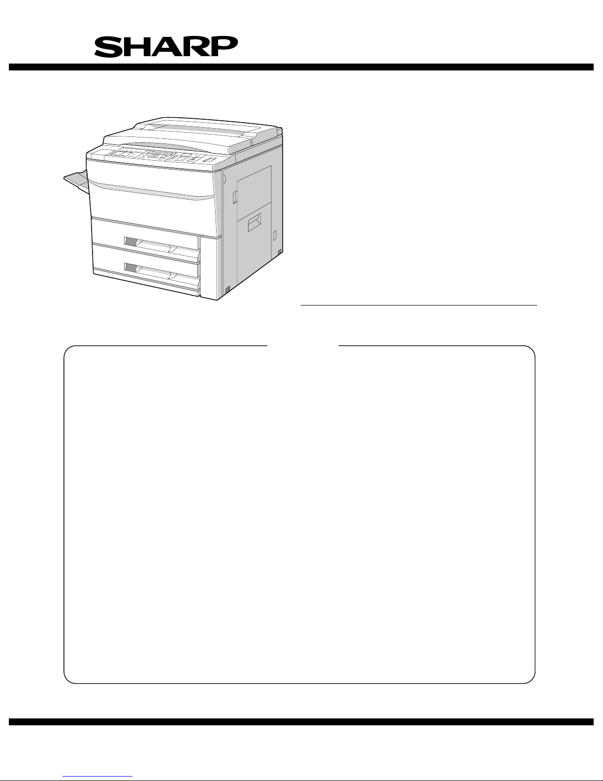
[1] PRODUCT OUTLINE
3. Major featur es
1. General description
The SF-2030 is medium class copier that produces 30 copies per
minute. The SF-2040 has all the standard features of medium class
copiers to provide high productivity in offices with improved versatility
for users.
2. Target users
Average copy volume: 8,000 ~ 12,000 copies/month
4. System outli ne
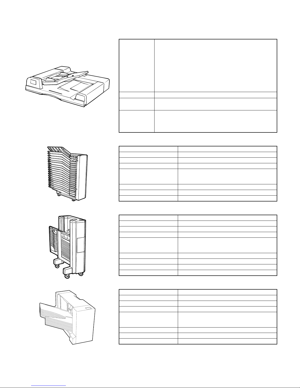
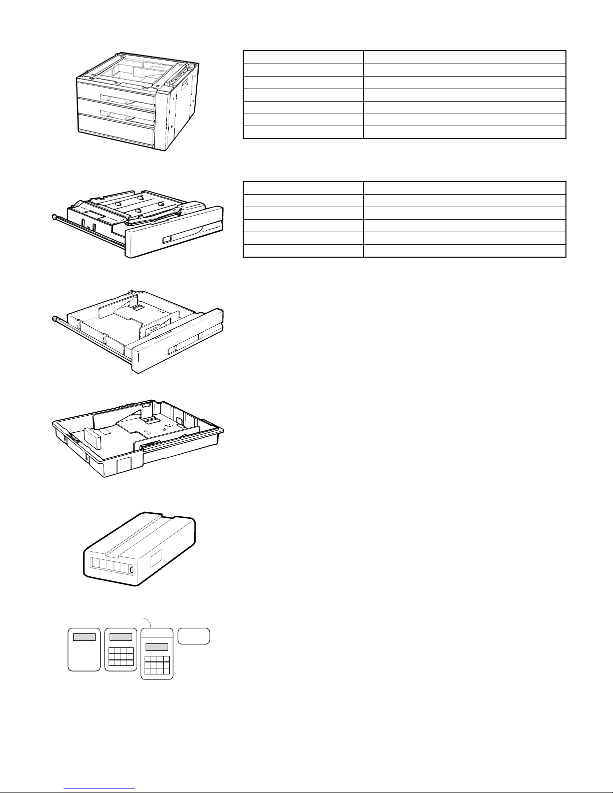
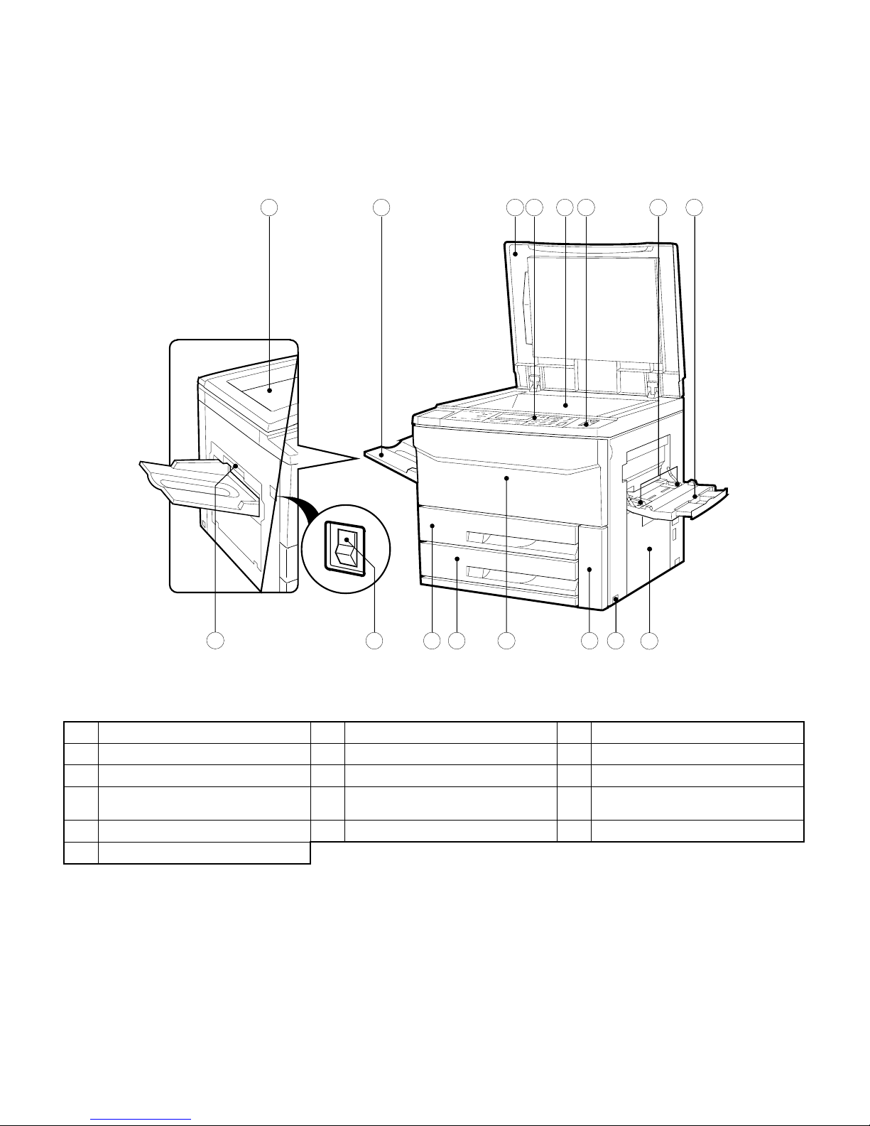
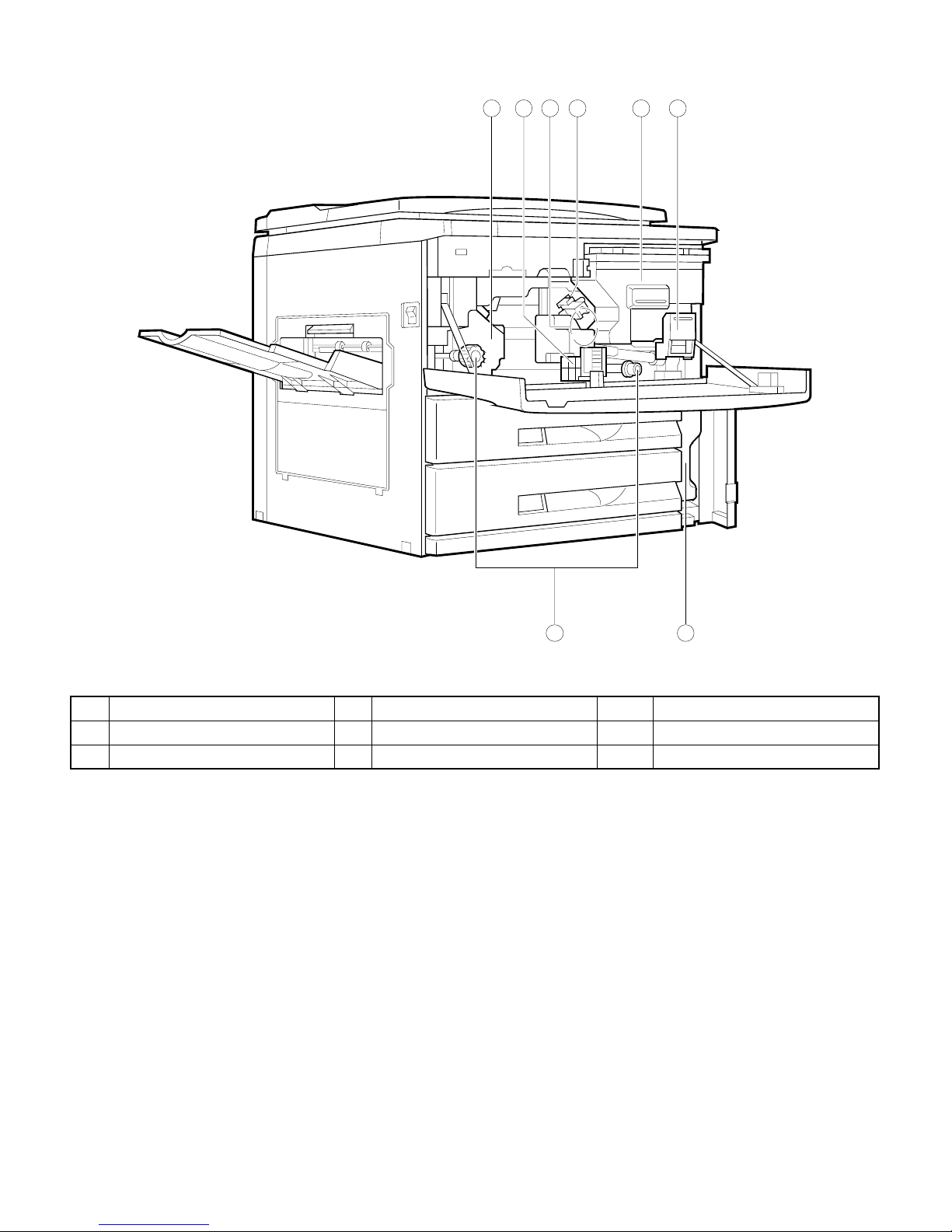
10-bin sorter (SF-S18)
(1) Compact body
Use of a front loading paper cassette.
(2) Serviceability and functionality
1 Use of a liquid crystal display.
2 Department control counter (standard provision, max. 50 depart-
ments).
3 Use of key operator codes.
(3) High copy performance
1 First copy time: 4.1sec
2 Job speed
S → S: 100%, D → D: 70%
(4) Options
Refer to the system outline below.
Automatic document feeder
(SF-A17)
20-bin sorter (SF-S15)
10-bin staple sorter (SF-S52)
Duplex module (SF-DM11)
Reversing automatic document feeder
(SF-A56)
Document cover (SF-CV13)
Cassette (SF-IC 11)
20-bin staple sorter (SF-S53)
Stand/500-sheet paper drawer (SF-D20)
(not sold in some areas)
Cassette (for replacement)
(SF-CM11)
Stand/1000-sheet paper drawer
(SF-D21)
1 – 1
Page 9
[2] PRODUCT SPECIFICATIONS
1. Basic specifica tio n
(1) Type
(2) Copy method
(3) Kinds of originals
(4) Copy speed
Desktop
Dry electrostatic copier
Sheet, book, three dimension al object
Thickness of original: Maximum 30mm in level with the original cover in use.
Weight of original: Maximum 1.8 kg (4 pounds)
Maximum original size: A3 (11" x 17"), Ledger
Original alignment: Center and left
Original sensor: Not used. (Provided in RADF/ADF.)
Sensing size
Option: RADF
Original loading capacity: 50 sheets
Original size: A3 to A5, Ledger ∼ Invoice
Original replace speed: 30 sheets per minute
Weight of original: 35 to 128 g/m2 (14 to 34 lbs)
Mixed paper feed mode: Possible (same width)
A3
B4
A4 (portrait)
A4 (landscape)
B5 (portrait)
B5 (landscape)
Ledger
Legal
Letter (portrait)
Letter (landscape)
NOTE: Copy speeds indicated in Enlargement and Reduction modes are the slowest speeds in the respec-
AB series; A3, B4, A4, A4R, A5
Inch series: Ledger, Legal, Letter, Letter R, Invoice
Actual (1:1) Enlarge (ratio) Reduce (ratio)
16 sheets per minute
18 sheets per minute
30 sheets per minute
23 sheets per minute
30 sheets per minute
23 sheets per minute
16 sheets per minute
18 sheets per minute
30 sheets per minute
23 sheets per minute
tive mode.
11 sheets per minute
(200%)
11 sheets per minute
(200%)
14 sheets per minute
(200%)
12 sheets per minute
(200%)
14 sheets per minute
(200%)
12 sheets per minute
(200%)
11 sheets per minute
(200%)
11 sheets per minute
(200%)
14 sheets per minute
(200%)
12 sheets per minute
(200%)
12 sheets per minute
(50%)
14 sheets per minute
(50%)
23 sheets per minute
(50%)
17 sheets per minute
(50%)
23 sheets per minute
(50%)
17 sheets per minute
(50%)
12 sheets per minute
(50%)
14 sheets per minute
(50%)
23 sheets per minute
(50%)
17 sheets per minute
(50%)
(5) First copy time
(6) Warmup time
(7) Multicopy
About 4.1 seconds from upper cassette
About 60 seconds
(With pre-heat feature)
Misfeed recovery time: 8 seconds, provided the machine is in the standard condition in 60 seconds
Maximum multicopy number: 999 sheets
after opening the door.
2 – 1
Page 10
(8) Magnification ratio
Fixed ratio
Zooming range: 50 to 200% (1% increments)
AB series: 4R+4E; 200, 141, 122, 115, 100, 86, 81, 70, 50%
Inch series: 4R+4E; 200, 141, 129, 121, 100, 95, 77, 64, 50%
(9) Exposure system Slit exposure and moving optical system (fixed original table)
(10) Paper feed
Copy size (maximum ~ minimum)
Method One tray + multi-manual feed
Capacity 500 + 50 sheets
AB series: A3 to A6R
Inch series: Ledger ∼ Invoice
AB series
Paper entry Paper size Paper weight Size selection Side, front
Upper cassette
(Option)
Lower cassette A5/B5/B5R
B5/B5R
A4/A4R/B4/A3
A4/A4R/B4/A3
A5: * With the option inner cassette used
56 ~ 80g/m2
15 ~ 21 lbs.
56 ~ 80g/m2
15 ~ 21 lbs.
Selection by way of
guide replacement
by the service
engineer
Selection by way of
guide replacement
by the service
engineer
Front, drawer in the
same body
(ADU compatibility
available)
By way of front,
inner cassette
Inch series
Paper entry Paper feed size Paper weight Size selection Side, front
Upper cassette
(Option)
Lower cassette Letter/Letter R/
Letter/Letter R/
Legal/Ledger
Legal/Ledger/
Invoice
* With the option inner cassette used
56 ~ 80g/m
15 ~ 21 lbs.
56 ~ 80g/m
15 ~ 21 lbs.
2
2
Selection by way of
guide replacement
by the service
engineer
Selection by way of
guide replacement
by the service
engineer
Front, drawer in the
same body
(ADU compatibility
available)
By way of front,
inner cassette
Initial setting
Japan
Copier upper stage * B5R — — * When shipping, the
Copier lower stage A3 Ledger A3
Option cassette module A4 Legal A4 SF-CM11
Multi-stage desk (1st stage)
Multi-stage desk (2nd stage)
Multi-stage desk (3rd stage)
LCD desk (1st stage)
LCD desk (2nd stage)
Inner cassette A3 Ledger A3 SF-IC11
B4
A3
—
—
Outside
Japan (Inch)
Letter R
—
—
—
Letter
Outside
Japan (AB)
domestic (Japan/Taiwan)
paper feed module is
attached.
A4R
—
—
—
A4 SF-D21 (Outside Japan only)
SF-D19 (Japan only)
SF-D20 (Outside Japan only)
Remark
Manual feed
Paper size: AB series:
Inch series:
Paper weight: Multifeed mode:
Single feed mode:
Kind of paper: Standard, Sharp designated paper, OHP
Detection size Inch series:
AB series:
A3 to A6R
Ledger ∼ Invoice
(Min. width: 100mm, Min. length: 139.7mm)
56 to 80 g/m2 (15 to 21 Ibs)
52 to 128 g/m2 (14 to 34 Ibs)
(A4 size or under, if above 105 g/m2 or 28 Ibs)
Available: Ledger, Legal, Letter, Letter (R), invoice
Available: A3, B4, A4, A4R, A5
2 – 2
Page 11
(11) Developing method Dry, two components magnetic brush method
(12) Charge method (–) DC saw-tooth electrode method
(13) Transfer method
(–) DC Corotron method
(14) Separation method AC Corotron method
(15) Fusing method Heat roller method
(16) Cleaning method Blade method
(17) Light source
(18) Blanking areas
(19) Automatic duplex
(20) Paper receive tray
and finishing
Halogen lamp
Void area: 3mm from the lead edge
Image loss: 3mm at maximum during the actual (1:1) copy mode
Option
(SF-DM11)
Location Copier upper module slot
Size AB series: A3, B4, A4, A4R, A5 (B5 and B5R only JAPAN)
Inch series: Ledger, Legal, Letter, Letter R
Capacity 50 sheets (below A4 or letter sizes) or 30 sheets (above B4 or 81⁄2" x 14" size)
Paper weight 56 to 80 g/m2 (15 to 21 Ibs)
Paper receive tray capacity 250 sheets
Finishing (Standard/Option) Option
Finisher function Sorted bin capacity Non-sorted bin capacity
10-bin sorter 30 sheets (A4) 100 sheets Shifting bins (SF-S18)
20-bin sorter 50 sheets (All sizes) 100 sheets Fixed bins (SF-S15)
20-bin staple sorter 50 sheets (A4) 250 sheets Shifting bins (SF-S53)
20-bin staple sorter 35 sheets (25 sheets if stapler used) 100 sheets Shifting bins (SF-S52)
2 – 3
Page 12
(21) Additional features
Availability
of feature
APS
AMS
Margin shift
DPCM
Edge erase
Cover insertion
Job memory F Recordable up to 9 jobs
Auditor F Allowes up to 50 departments.
Message display F
Key operator program F
Communication
Process control F
Auto start F From the energy save mode.
Auto tray switching F
Priori ty se lec tio n of
tray
Vendor F
F
F
F
F
F
F
F
✕
Overseas: Available when
RADF/ADF is used
Inhibited when mixed paper feed/
Available when RADF/ADF is
used APS: Auto paper selection
9mm shift (S → S), with
adjustment function
Enlarge not permitted.
Combination with the duplex
function allowed.
7 to 12mm wide depending on
the size. Equivalent to SF2022/2027.
Selection of cover/rear or
cover/both
Bi-directional. Option I/F PWB
(available from service parts.)
AMS: Auto magnification ratio
selection
DPCM: Dual page copy mode
Binding margin shift
Width AB series Inch series
Single sides to single sided 9mm 1/4"
Double sided to single sided 9mm 1/4"
Single sided to double sided (front) 9mm 1/4"
Single sided to double sided (reverse) 9mm 1/4"
Double sided to double sided (front) 9mm 1/4"
Double sided to double sided (reverse) 9mm 1/4"
Frame edge erase
AB series Inch series
Size Deleted width (mm) Size Deleted width (mm)
A3 11.5±3 Ledger 11.5±3
B4 9.5±3 Legal 7 ±3
A4 11.5±3 Letter 11.5±3
A4R 10 ±3 Letter R 7 ±3
B5 9.5±3 Invoice 7 ±3
B5R 8 ±3
(22) Power supply Voltage:
Frequency:
100V, 110V, 120V, 127V, 220 ∼ 230V, 240V
50/60Hz, universal
(23) Power consumption Maximum power consumption: 1.5KW, maximum, with options used
(24) Appearance WxDxH (mm) 633 x 650 x 567 (at the top of the table glass)
633x 650 x 607 (at the top of the original cover)
Occupied area (W x D in mm) 1205 x 650 (with the paper receive tray and manual feed bypass open
Weight: Main body About 62Kg
Paper feed module: 3.9Kg
Original cover: 1.5Kg
2 – 4
Page 13
(25) Accessories
Destination Japan SEC SECL SEEG SUK SCA AB agent Inch agent
Drum Installed when
Developer (Black) F ЧЧЧЧЧЧЧ
Toner cartridge F ЧЧЧЧЧЧЧ
Original cover Standard
Paper exit tray 1
Original table × F ×
Toner collection
container
Operation manual Japanese Exclusive English English/French GG: German
Dust cover F × F (Part)
Zooming ratio table F
ROM language Japanese English English GG: German
Key sheet Japanese English English/French GG: German
Other printed matters:
Delivery/installation report (Japan/SEEG), SCA warranty, Warranty registration (SUK), Maintenance card, Counter contract × 2 (Japan)
*1
: Retractable (Japan), Fixed (Outside Japan)
*1
shipping.
provision
Installed when
shipping.
Option Option Option Option Option Standard provision
Installed when
shipping.
SEL = English/French packed together. SEEG (BG) = Treated in a kit.
Separately
packed.
F (4 pcs.) One is installed when shipping.
BG: None
BG: None
BG: None
Separately
packed.
F
Exclusive English English English/French/
English English English/French/Spanish depending on
English English English, partly
Installed when
shipping.
Partly packed. Partly packed.
Arabic
Typical example
the destination.
Spanish
English/
Spanish
Typical example
English, partly
Spanish
2. Consumables
SEC
No. Name Content Life Product name Package Remark
1 Drum OPC drum × 1 80K SF-230DR 10
2 Developer (Black) Developer (850g) × 10 80K (× 10) SF-230MD1 1 (SF-230ND1) × 10 = SF-230MD1
3 Toner (Black) Toner cartridge (600g) × 10 15K (× 10) SF-230MT1 1 (SF-230NT1) × 10 = SF-230MT1
4 Upper heat roller kit Upper heat roller × 1 160K SF-230UH 5 For replacement of the fusing separation pawl (80K
Fusing separation pawl (Upper) × 4
Fusing gear × 1
5 Lower heat roller kit Lower heat roller × 1 160K SF-240LH 5 For replacement of the fusing separation pawl (80K
Fusing separation pawl (Lower) × 2
6 80K maintenance kit Cleaner blade × 1 80K SF-235KA1 5
Charging blade unit × 1
Drum separation pawl unit × 1
7 Cleaner blade Cleaner blade × 10 80K (× 10) SF-222CB 1
8 Upper cleaning roller Upper cleaning roller × 10 80K (× 10) SF-240UR 1 (SF-240RU) × 10 = SF-240UR
9 Lower cleaning roller Lower cleaning roller × 10 80K (× 10) SF-235CR2 1
10 Staple cartridge Staple cartridge (3 pcs. pack) × 10 SF-LS51 1 Common to the one for the staple sorter
11 Staple cartridge Staple cartridge × 5 5,000 times
× 5
SD-LS20 10 Common to the one for the staple sorter
* For Toner collection container (4 pcs./80K)/Screen grid (80K)/Charger wire (80K)/Ozone filter (80K)/Toner reception seal (160K)/DV seal (160K),
use service parts. The charging plate nit (80K) and drum separation pawl unit (80K) are also available as service parts.
life) at every 80K, use the service part.
life) at every 80K, use the service part.
(SF-S51).
(SF-S51) x 10 = SF-LS51
(SF-S53).
(SD-SC20) x 5 = SD-LS20
2 – 5
Page 14
SECL
No. Name Content Life Product name Package Remark
1 Drum OPC drum × 1 80K SF-2300R 10
2 Developer (Black) Developer (850g) × 10 80K (× 10) SF-230MD1 1 (SF-230ND1) × 10 = SF-230MD1
3 Toner (Black) Toner cartridge (600g) × 10 15K (× 10) SF-230MT1 1 (SF-230NT1) × 10 = SF-230MT1
4 80K maintenance kit Upper cleaning roller × 1 80K SF-240KA 1
Lower cleaning roller × 1
Cleaner blade × 1
Toner collection container × 4
Fusing separation pawl (Upper) × 4
Fusing separation pawl (Lower) × 2
Screen grid × 1
Charging plate unit × 1
Drum separation pawl unit × 1
5 160K maintenance kit Upper heat roller × 1 160K SF-230KB 1
Lower heat roller × 1
Toner reception seal × 1
DV seal × 1
Low speed gear × 1
6 Staple cartridge Staple cartridge (3 pcs. pack) × 1 SF-SC51 10 Common to the one for the staple sorter
7 Staple cartridge Staple cartridge × 5 5,000 times
× 5
SD-LS20 10 Common to the one for the staple sorter
(SF-S51)
(SF-S53)
(SD-SC20) x 5 = SD-LS20
SEEG, SUK
No. Name Content Life Product name Package Remark
1 Drum OPC drum × 1 80K SF-230DM 10
2 Developer (Black) Developer (850g) × 10 80K (× 10) SF-230LD1 1 (SF-230DV1) × 10 = SF-230LD1
3 Toner (Black) Toner cartridge (600g) × 10 15K (× 10) SF-230LT1 1 (SF-230T1) × 10 = SF-230LT1
4 80K maintenance kit Upper cleaning roller × 1 80K SF-240KA 1 Distinguished from A3SF240KF to cope with EAN
Lower cleaning roller × 1
Cleaner blade × 1
Toner collection container × 4
Fusing separation pawl (Upper) × 4
Fusing separation pawl (Lower) × 2
Screen grid × 1
Charging plate unit × 1
Drum separation pawl unit × 1
5 160K maintenance kit Upper heat roller × 1 160K SF-230KB 1 Distinguished from A3SF230KB to cope with EAN
Lower heat roller × 1
Toner reception seal × 1
DV seal × 1
Fusing gear × 1
6 Staple cartridge Staple cartridge (3 pcs. pack) × 1 SF-SC51 10 Common to the one for the staple sorter (SF-S51).
7 Staple cartridge Staple cartridge × 5 5,000 times
× 5
SF-LS20 10 Common to the one for the staple sorter (SF-S53).
code.
code.
(SD-SC20) x 5 = SD-LS20
2 – 6
Page 15

SCA, SCNZ, Middle East, Africa
No. Name Content Life Product name Package Remark
1 Drum OPC drum × 1 80K SF-230DM 10
2 Developer (Black) Developer (850g)× 1 80K (× 10) SF-230LD1 1 (SF-230DV1) × 10 = SF-230LD1
3 Toner (Black) Toner cartridge (600g)× 1 15K (× 10) SF-230LT1 1 (SF-230T1) × 10 = SF-230LT1
4 80K maintenance kit Upper cleaning roller × 1 80K SF-240KA 1
Lower cleaning roller × 1
Cleaner blade × 1
Toner collection container × 4
Fusing separation pawl (Upper) × 4
Fusing separation pawl (Lower) × 2
Screen grid × 1
Charging plate unit × 1
Drum separation pawl unit × 1
5 160K maintenance kit Upper heat roller × 1 160K SF-230KB 1
Lower heat roller × 1
Toner reception seal × 1
DV seal × 1
Fusing gear × 1
6 Staple cartridge Staple cartridge (3 pcs. pack) × 1 SF-SC51 10 Common to the one for the staple sorter (SF-S51)
7
Staple cartridge
Staple cartridge × 5 5,000 times
× 5
SD-LS20 10 Common to the one for the staple sorter (SF-S53)
(SD-SC20) x 5 = SD-LS20
Asia, Middle/South America
No. Name Content Life Product name Package Remark
1 Drum OPC drum × 1 80K SF-230DR 10
2 Developer (Black) Developer (850g)× 10 80K (× 10) SF-230CD1 1 (SF-230SD1) × 10 = SF-230CD1
3 Toner (Black) Toner cartridge (600g)× 10 15K (× 10) SF-230CT1 1 (SF-230ST1) × 10 = SF-230CT1
4 80K maintenance kit Upper cleaning roller × 1 80K SF-240KA 1
Lower cleaning roller × 1
Cleaner blade × 1
Toner collection container × 4
Fusing separation pawl (Upper) × 4
Fusing separation pawl (Lower) × 2
Screen grid × 1
Charging plate unit × 1
Drum separation pawl unit × 1
5 160K maintenance kit Upper heat roller × 1 160K SF-230KB 1
Lower heat roller × 1
Toner reception seal × 1
DV seal × 1
Fusing gear × 1
6 Staple cartridge Staple cartridge (3 pcs. pack) × 1 SD-SC51 10 Common to the one for the staple sorter (SF-S51)
7 Staple cartridge Staple cartridge × 5 5,000 times
× 5
SD-LS20 10 Common to the one for the staple sorter (SF-S53)
(SD-SC20) x 5 = SD-LS20
2 – 7
Page 16
3. Environmen tal requ ir em en ts
Conditions required for proper operation of the machine, as well as
assurance of copy quality, the following are requested.
1 Standard conditions
Recommended temperature range at 20 to 25 Centigrade (68 to
77 degrees F) and humidity range at 65 ± 5%RH.
2 Operating conditions
Humidity
80%
60%
20%
15˚C
Temperature
3 Shipping conditions
Humidity
90%
60%
20%
-20˚C
Temperature
4 Consumables storage conditions
Humidity
90%
30˚C 35˚C
30˚C
45˚C
20%
-5˚C
40˚C
Temperature
2 – 8
Page 17
[3] OPTIONS SPECIFI C ATIONS
1. SF-A17/A56
2. SF-S15
Acceptable
originals
Power supply Drawn from the copier
Weight SF-A17: Approx. 22.1 lbs. (10 kg)
Dimensions SF-A17: 22-31/64″ (W) × 20-33/64″ (D) × 4-11/32″ (H)
Name 20-bin sorter
No. of bins 20 bins
Paper collection Copy face up
Capacity per bin Max. 50 sheets (100 sheets: Top bin)
Allowable paper size/weight
for collating
Power source Supplied from the copier.
Dimensions 500mm (W) × 520mm (D) × 957mm (H)
Weight About 13kg
Weight: Single-sided originals: 14 to 34 lbs.
Two-sided originals (SF-A56 only): 14 to 34 lbs. for
5-1/2″ × 8-1/2″ and 8-1/2″ × 11″ originals.
14 to 29 lbs. for 8-1/2″ × 14″ and 11″ × 17″ originals.
Size: 5-1/2″ × 8-1/2″ to 11″ × 17″
Capacity: Up to 50 sheets for 5-1/2″ × 8-1/2″, 8-1/2″ × 11″ , and
8-1/2″ × 14″ originals provided the total aggregate
thickness does not exceed 1/4″ or 6.5 mm (14 to 20
lbs.) or 3/16″ or 5 mm (21 to 34 lbs.)
Up to 30 sheets for 11″ × 17″ originals.
SF-A56: Approx. 24.3 lbs. (11 kg)
(571 mm (W) × 521 mm (D) × 110 mm (H))
SF-A56: 23-5/16″ (W) × 20-33/64″ (D) × 4-11/32″ (H)
(592 mm (W) × 521 mm (D) × 110 mm (H))
Max. A3, Min.: B5 (Min. A6 for non-sort)
Non-sort: 52 ∼ 128g/m2,
Sort/Grouping: 56 ∼ 80g/m
2
3. SF-S53
4. SF-S18
Name Staple sorter
No. of bins 20 bins
Paper collection Copy face up
Capacity per bin Max. 50 sheets (250 sheets: Top bin)
Allowable paper size/weight
for collating
No. of sheets for stapling 50 sheets (80g/m2)
Power source Supplied from the copier.
Dimensions 475mm (W) × 597mm (D) × 995mm (H)
Weight About 42.1kg
Name 10-bin sorter
No. of bins 10 bins
Reception method Copy face up
Capacity per bin Max. 30 sheets (Top bin: 100 sheets)
Collatable paper size/weight
Power source Supplied from the copier.
Dimensions 335mm(W) × 493mm(D) × 298mm(H)
Weight About 7kg
Max.: A3, Min.: B5 (Non-sort: Min. A5),
Non-sort: 52 ∼ 128g/m2,
Sort/staple sort/grouping: 56 ∼ 89g/m
Max. A3, Min. A5 (Non-sort, Min. A6)
Non-sort: 52 ∼ 128g/m2,
Sort/group: 56 ∼ 80g/m
2
2
3 – 1
Page 18
5. SF-D20/D21
6. SF-DM11
7. SF-CM11
Name 2-cassette paper feed desk
Paper size and capacity 550 sheets of A3, B4, A4, or B5 for each cassette
Paper weight 56 ∼ 80g/m
Paper transport system Roller transport (center reference)
Power source Supplied from the copier.
Dimensions 600mm (W) × 625mm (D) × 451mm (H)
Weight About 32kg
Name Duplex module
Paper size A3 ∼ B5
Paper weight 56 ∼ 80g/m
Capacity A3/B4: 30 sheets, A4/B5: 50 sheets
Power source Supplied from the copier.
Weight About 6kg
Cassette module
2
2
• Equivalent to the upper cassette of the copier body. The optional 2-cassette
paper feed desk can be attached.
8. SF-IC11
9. SF-71A (counter ), SF -7 1B (socket)
9
9
9
9
9
10. Other counters
Inner cassette
• Paper cassette for replacement of the lower cassette.
• Personal counter
Card-type department counter (SF-EA11)
Password-system department counter (SF-EA12)
Counter commander (SF-EA13)
1 1. Desk SF-D S15
3 – 2
Page 19
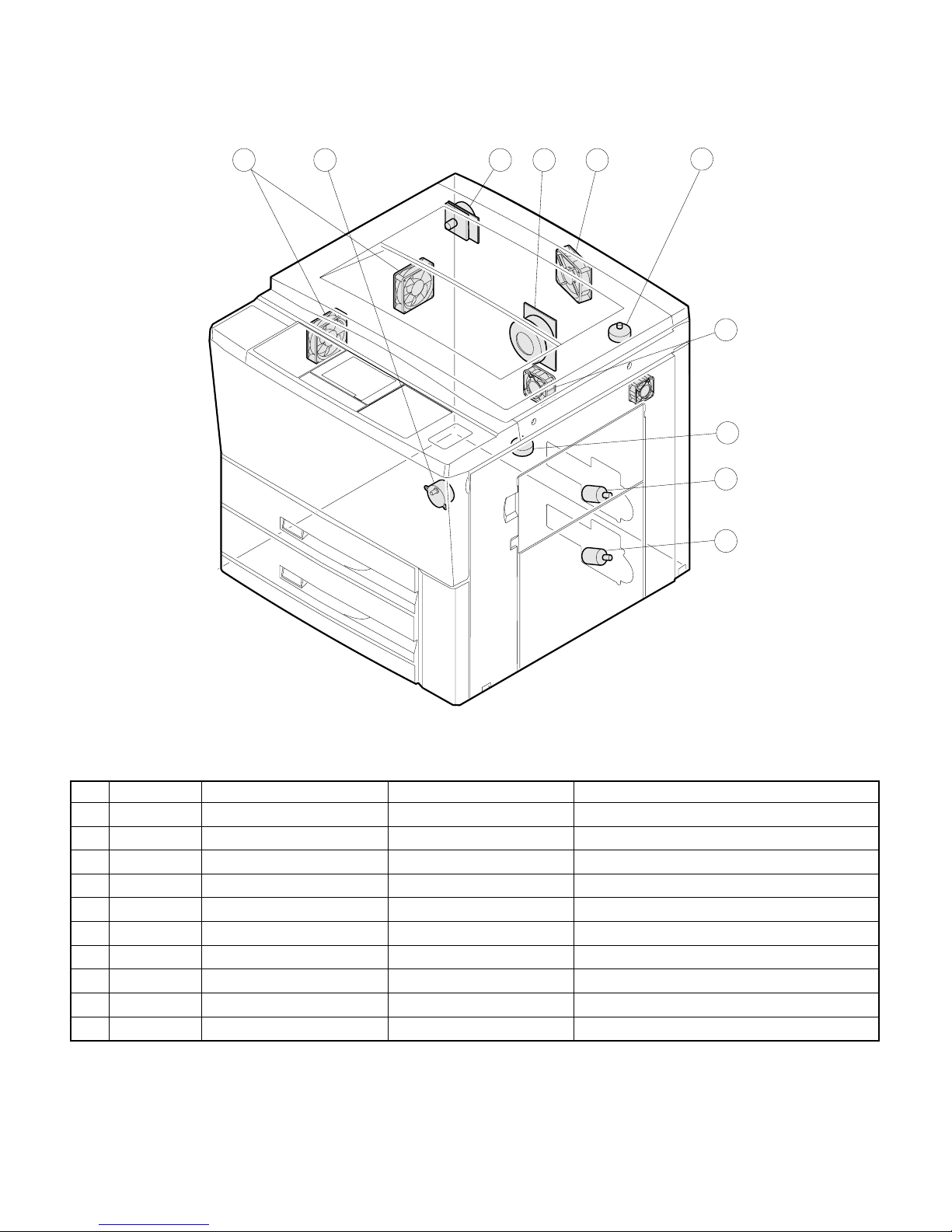
[4] COMPONENT IDENTIFI CATION
1. External view
1 2 3 4 5 6 7
8
Document holder
1
Operation panel
4
Manual feed tray paper guides
7
Power switch
F
Front cover
I
Side cover
L
9
2
5
8
G
J
10 11 12 13 14 15
Exit tray
Document glass
Manual feed tray
Duplex module or 500-sheet paper
drawer (optional)
Toner collecting container cover
3
6
9
H
K
16
Document cover (optional)
Paper clip tray
Exit area cover
Lower paper tray
Handles
4 – 1
Page 20
17 18 20 19 21 23
Fusing unit
M
Photoconductive drum
P
Toner hopper lock lever
S
Transport lever
N
Toner hopper
Q
Toner collection container
T
22 24
Corona unit
O
Roller rotating knobs
R
4 – 2
Page 21
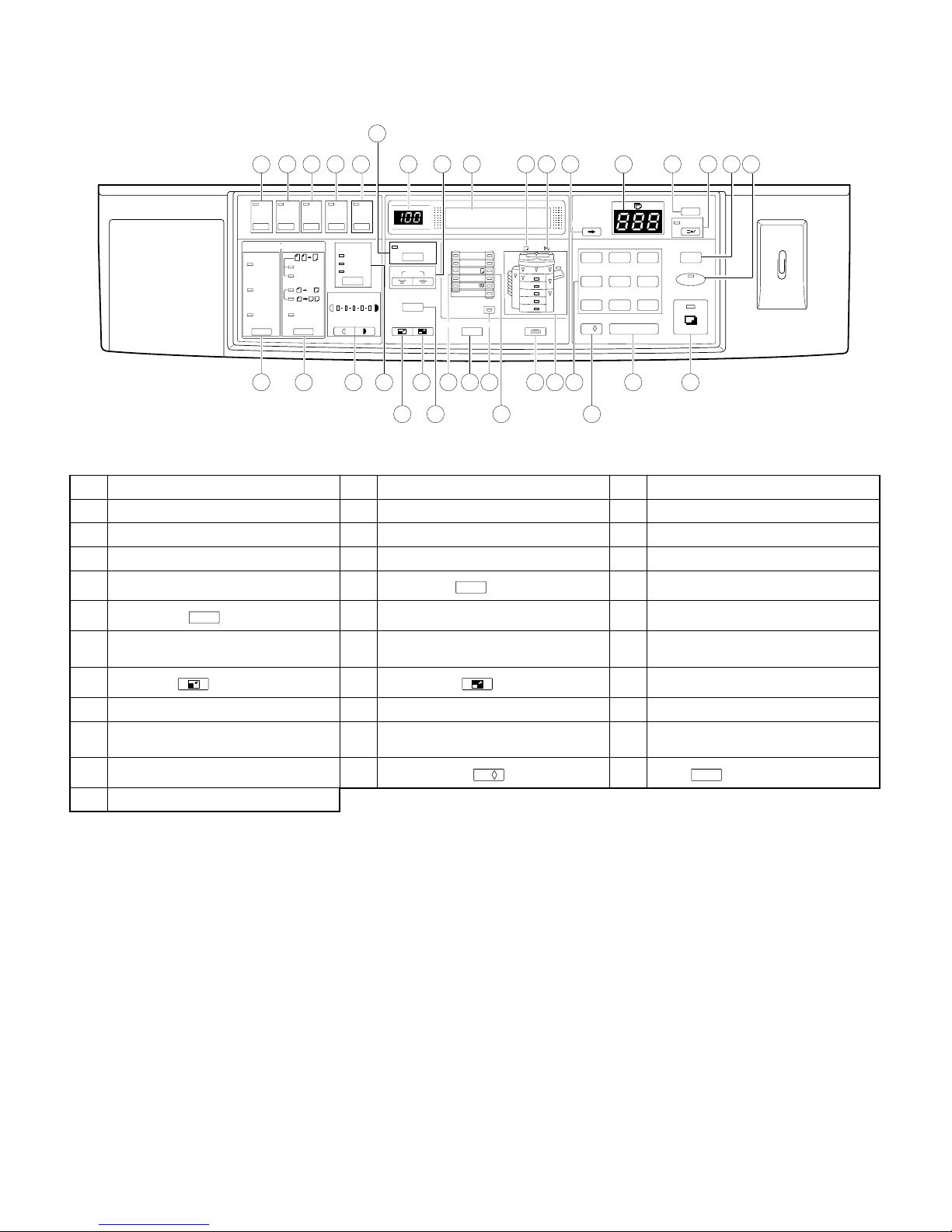
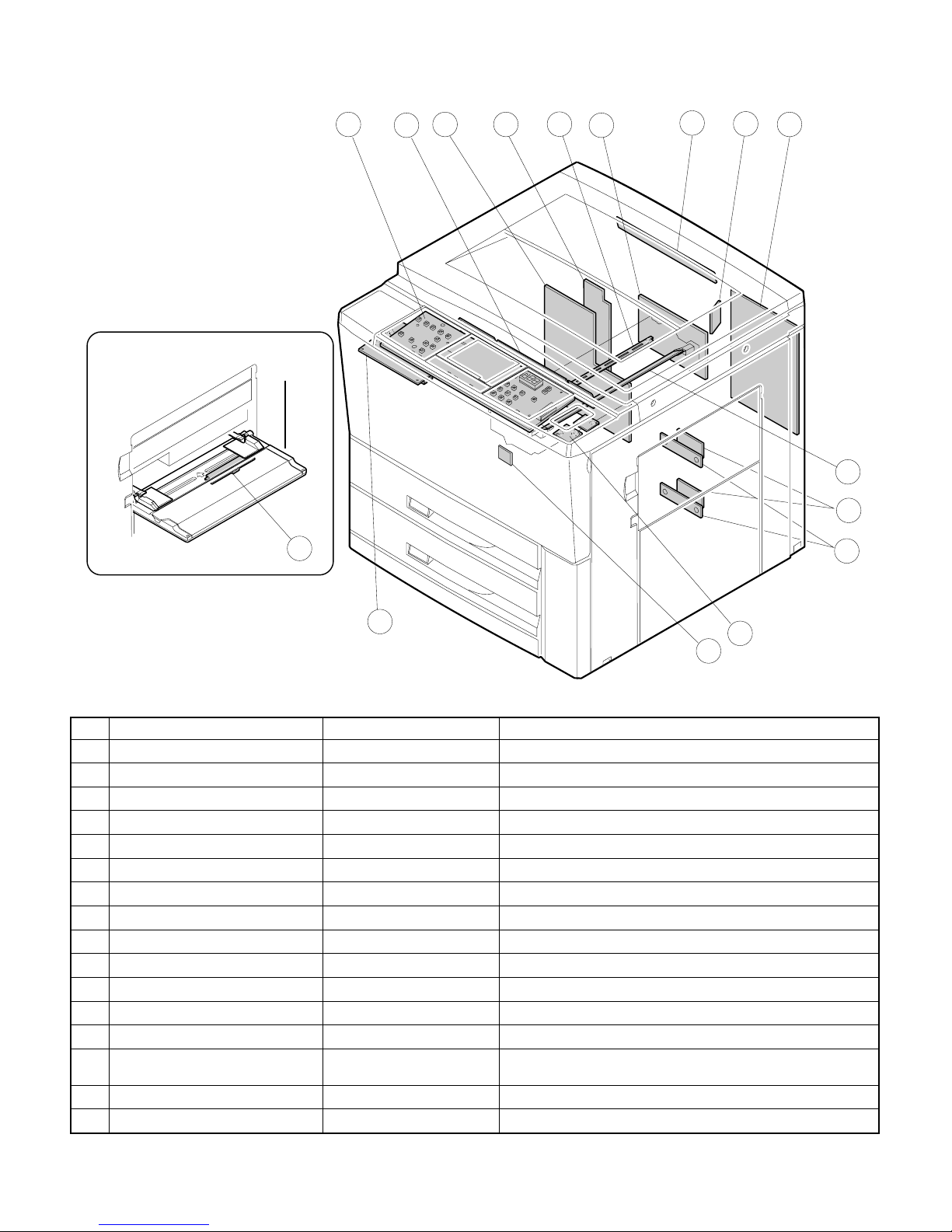
2. Operation panel
CA
6
2
3
4
1
5
7
8
9
101112
13
14
15
16 17
COVERS key and indicator
1
MARGIN SHIFT key and indicator
4
COPY RATIO display
7
Paper required indicator
F
Copy quantity display
I
CLEAR ALL ( ) key
L
ORIGINAL TO COPY key and
O
indicators
Reduction ( ) key
R
ORIGINAL SIZE indicators
U
PAPER SIZE indicators
X
10-key pad
[
START key and indicator
^
1
2
2
1
MARGIN
SHFT
EXPOSURE
AUTO
MANUAL
PHOTO
12345
LIGHT DARK
DUAL PAGE
COPY
AUTO IMAGE
ZOOM
100%
%
ORIGINAL
SIZE
11 x 17
8½ x 14
8½ x 11
8½ x 5½
8½ x 11
EXTRA
AUTO PAPER
SELECT
ORIGINAL SIZE ENTER
26
CENTER
COVERS
SORTER
SORT
STAPLE
SORT
GROUP
EDGE
ERASE
ERASE
ORIGINAL TO COPY
11
(ORIGINALS)
EVEN NUMBER
ODD NUMBER
2
2
PRE-COUNT
ORIGIN ALS
18 19 20 21 23 25 27
22 24 28
CENTER ERASE key and indicator
2
DUAL PAGE COPY key and indicator
5
ZOOM keys
8
Misfeed indicator
G
PROGRAM ( ) key
J
POWER SAVE indicator
M
LIGHT and DARK keys and indicators
P
Enlargement ( ) key
S
ORIGINAL SIZE ENTER key
V
TRAY SELECT key
Y
AUDIT CLEAR ( ) key
\
P
PAPER
SIZE
0/
SCROLL DISPLAY
1
2
3
5
4
78
30
AUDIT CLEAR
0/ C
TRAY SELECT
29 31 33 34
6
9
32
EDGE ERASE key and indicator
3
AUTO IMAGE key
6
Message display
9
SCROLL DISPLAY key
H
INTERRUPT key and indicator
K
SORTER key and indicators
N
EXPOSURE key and indicators
Q
100% key
T
AUTO PAPER SELECT indicator
W
Paper feed location/misfeed location
Z
indicators
Clear ( ) key
]
PROGRAM
P
INTERRUPT
CLEAR ALL
CA
POWER SAVE
START
C
4 – 3
Page 22
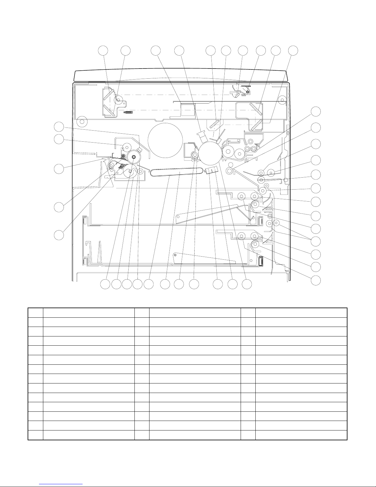
3. Internal view
27
26
28
25
21 5 6
8
3 4
1097
12
13
30
29
31
32
34
35
24
#2 mirror
1
Copy lamp
4
Blank lamps
7
#5 mirror
F
Resist roller
I
Separation corona
L
Suction unit
O
Lower heat roller
R
Upper separator pawl
U
Delivery select gate
X
Counter manual feed roller
[
Upper paper feed roller
^
Lower paper feed roller
a
Lower cleaning roller
d
23
22
21 19
40
2
5
8
G
J
M
P
S
V
Y
\
_
b
18
20
#3 mirror
Lens unit
#6 mirror
—
Transfer corona
Drum separator pawl
Suction belts
Heater lamp
Upper cleaning roller
Manual feed takeup roller
Transport roller (upper)
Upper paper feed reverse roller
Lower paper feed reverse roller
17 16 15
14
#1 mirror
3
Main corona unit
6
#4 mirror
9
Developing tank
H
Drum
K
Cleaner unit
N
Upper heat roller
Q
Lower separator pawl
T
Fuser thermistor
W
Manual feed paper feed roller
Z
Transport roller (lower)
]
Upper paper takeup roller
‘
Lower paper takeup roller
c
36
33
37
38
39
4 – 4
Page 23
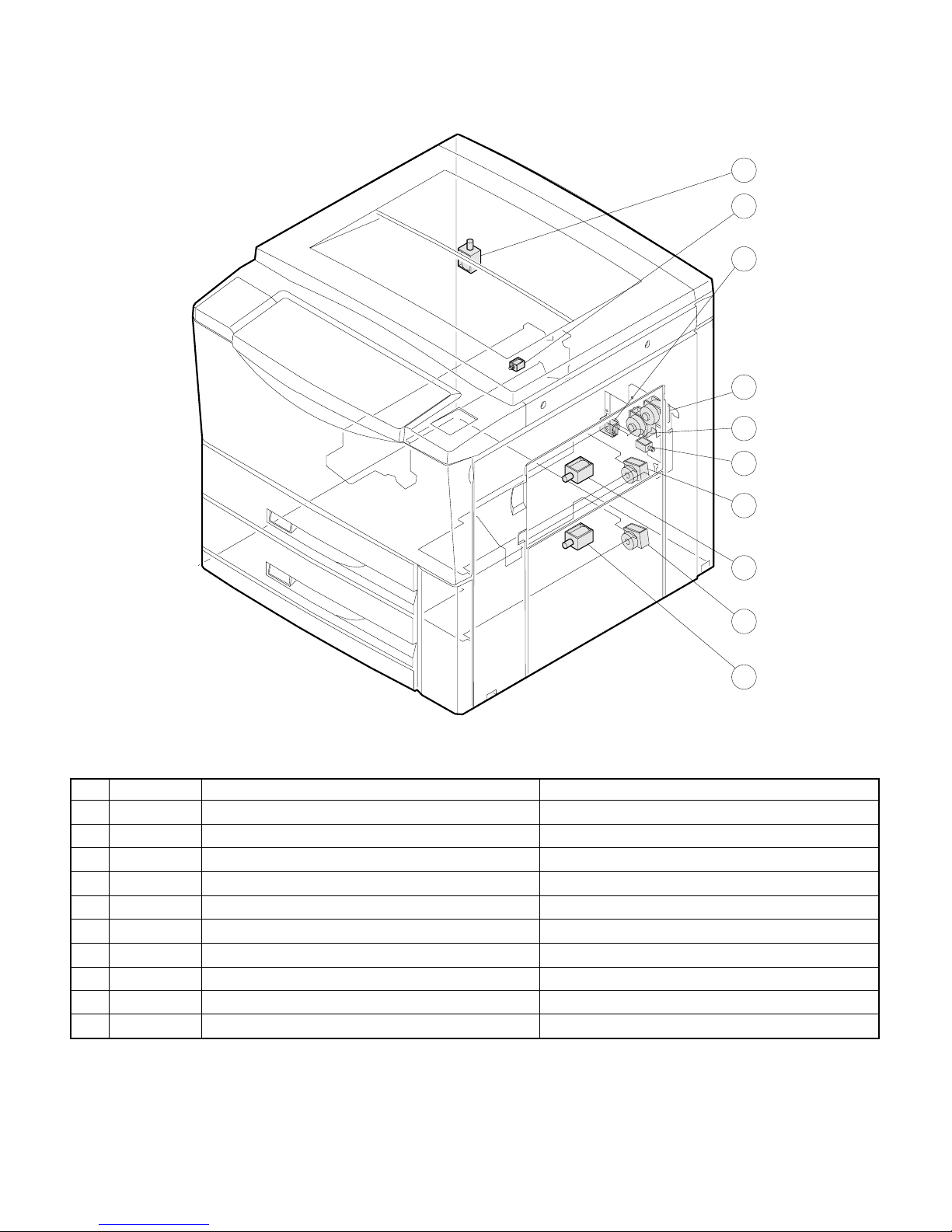
4. Clutches, sol eno id s
10
9
8
7
6
5
3
Signal name Name Function
1
2
3
4
5
6
7
8
9
F
CPFS1 Upper cassette paper feed solenoid For tensioning takeup roller
CPFS2 Lower cassette paper feed solenoid For tensioning takeup roller
CPFC1 Upper cassette paper feed clutch For actuating paper feed roller
CPFC2 Lower cassette paper feed clutch For actuating paper feed roller
MPFS Manual paper feed solenoid For tensioning takeup roller
TRCL Transport roller clutch (low) For actuating transport roller (low)
TRCH Transport roller clutch (fast) For actuating transport roller (fast)
RRC Resist roller clutch For actuating resist roller
PSPS Paper separation solenoid For actuating paper separation solenoid
DGS Duplex copy gate solenoid For actuating duplex copy gate
1
4
2
4 – 5
Page 24
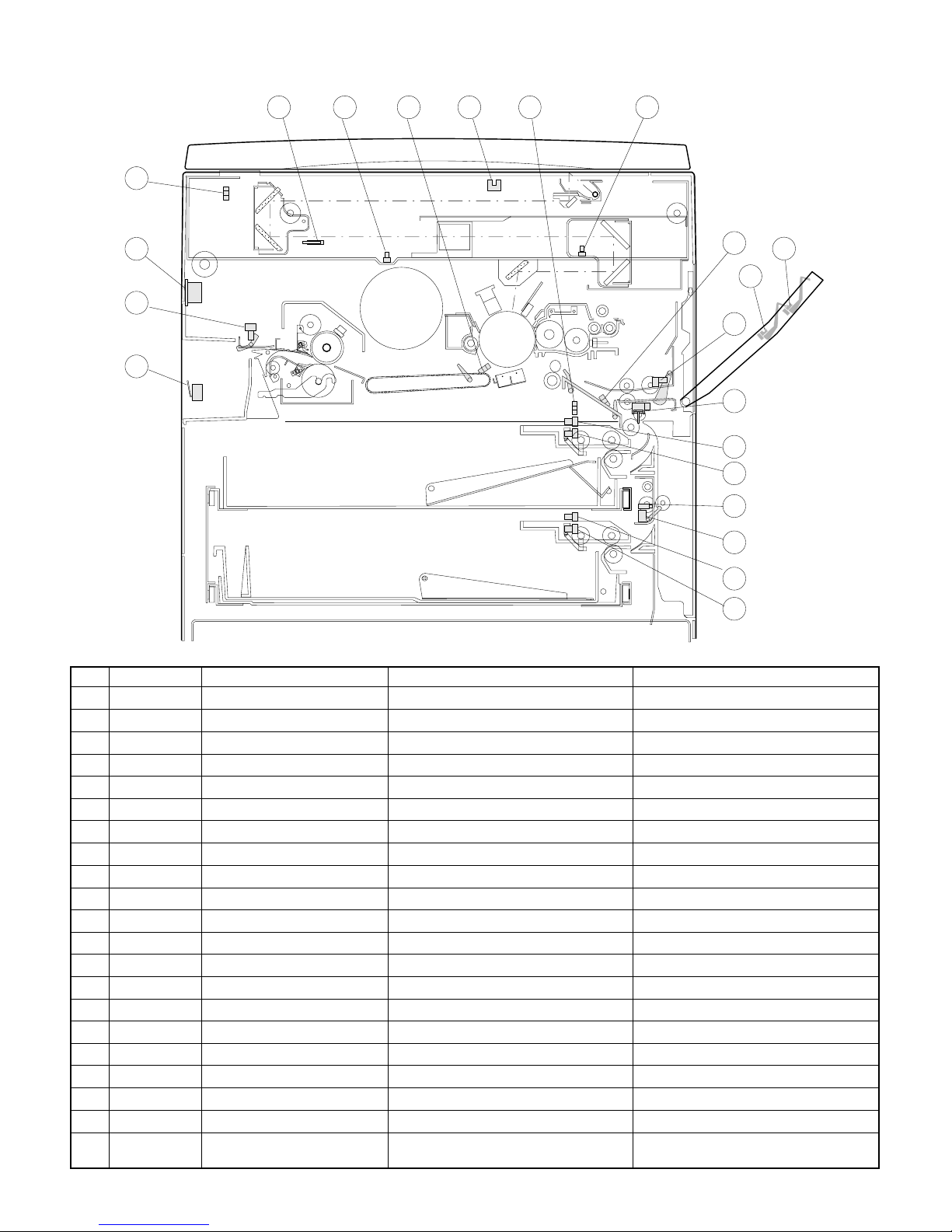
5. Sensors
5
6 7
8
9
10
4
3
11
21
20
2
12
1
13
14
15
16
17
Signal name Type Name Output
1
2
3
4
5
6
7
8
9
F
G
H
I
J
K
L
M
N
O
P
Q
CSWL Microswitch Cover switch, (left) On when closed
POD Transmssive photosensor Paper exit sensor Low when paper passes over
P-SW See-saw switch AC power switch —
MHPS Transmissive photosensor Mirror home position sensor High when scanner at home postion
CSWF Microswitch Cover switch, (front) On when closed
LHPS Transmissive photosensor Lens home position sensor Low when lens at home postion
PSD Transmissive photosensor Paper separation sensor High when paper passes over
OCSW Transmissive photosensor Original cover switch Low when cover is open
PPD2 Transmissive photosensor Paper transport sensor Low when paper passes over
MBHPS Transmissive photosensor Mirror home position sensor Low when mirror at home position
PPD1 Transmissive photosensor Paper transport sensor-1 Low when paper passes over
PED1 Transmissive photosensor Manual feed paper sensor Low when paper passes over
TFD Transmissive photosensor Full waste toner sensor Low when full waste toner detected
LUD1 Transmissive photosensor Upper cassette liftup sensor Low when lift plate detected
PED2 Transmissive photosensor Upper cassette paper sensor Low when paper detected
CSWR Microswitch Doorswitch (right) On when closed
PID Transmissive photosensor Paper transport sensor High when paper passes over
LUD2 Transmissive photosensor Lower cassette liftup sensor Low when lift plate detected
PED3 Transmissive photosensor Lower cassette paper sensor Low when paper detected
PLS1 Transmissive photosensor Manual tray paper length sensor Low when detected
PLS2 Transmissive photosensor
Manual tray paper length sensor
(Inch series only)
Low when detected
18
19
4 – 6
Page 25
6. Motors
9 12 85
4
10
3
6
7
Signal name Name Type Function
1
2
3
4
5
6
7
8
9
F
MM Main motor DC, brushless Driving copier and ADU option
SM Mirror motor DC, brushless Driving optical system mirror bases A and B
LEM Lens motor DC, stepping Driving optical lens
MBM #4/5 mirror base motor DC, stepping Driving optical mirror base C
TM Toner motor DC, synchronous Supplying toner
LUM1 Upper cassette liftup motor DC, brush Lifting upper paper feed cassette baseplate
LUM2 Lower cassette liftup motor DC, brush Lifting lower paper feed cassette baseplate
CFM Cooling fan motor DC, brushless Cooling optical system
VFM Ventilation fan motor DC, brushless Ventilating fuser area
SFM Suction fan motor DC, brushless Ventilating process unit area aid in paper transport
4 – 7
Page 26
7. Board list
14
2
10
3
12
116
5
7
1
4
9
8
15
16
13
Name Type Function
Main PWB Japan/Export Primary control of copier functions
1
Operation PWB Common Display
2
AC PWB Japan/Export, 100V/200V Supplying AC power
3
Blank lamp PWB Common Controlling blank lamps
4
Original sensing light emitting PWB Japan Sensing original size
5
Original sensor light receive PWB Japan Sensing original size
6
AE PWB Common Automatic exposure sensor
7
Cassette paper size PWB Common Sensing cassette paper size
8
Liftup motor PWB Common Driving paper cassette bottom plate liftup
9
DC power supply unit 100V/200V series Supplying DC power
F
High voltage transformer Common Supplying process unit high voltage and developing bias voltage
G
Discharge lamp Common Driving discharge lamps
H
Process control VR PWB Common Process sensor sensitivity adjustment
I
Manual feed paper size sensor
J
PWB
LCD control PWB Japan/Export LCD display drive/control
K
LCD invertor PWB Common LCD power invertor circuit
L
Japan/Export Paper size detection (Japan, portrait only)
4 – 8
Page 27
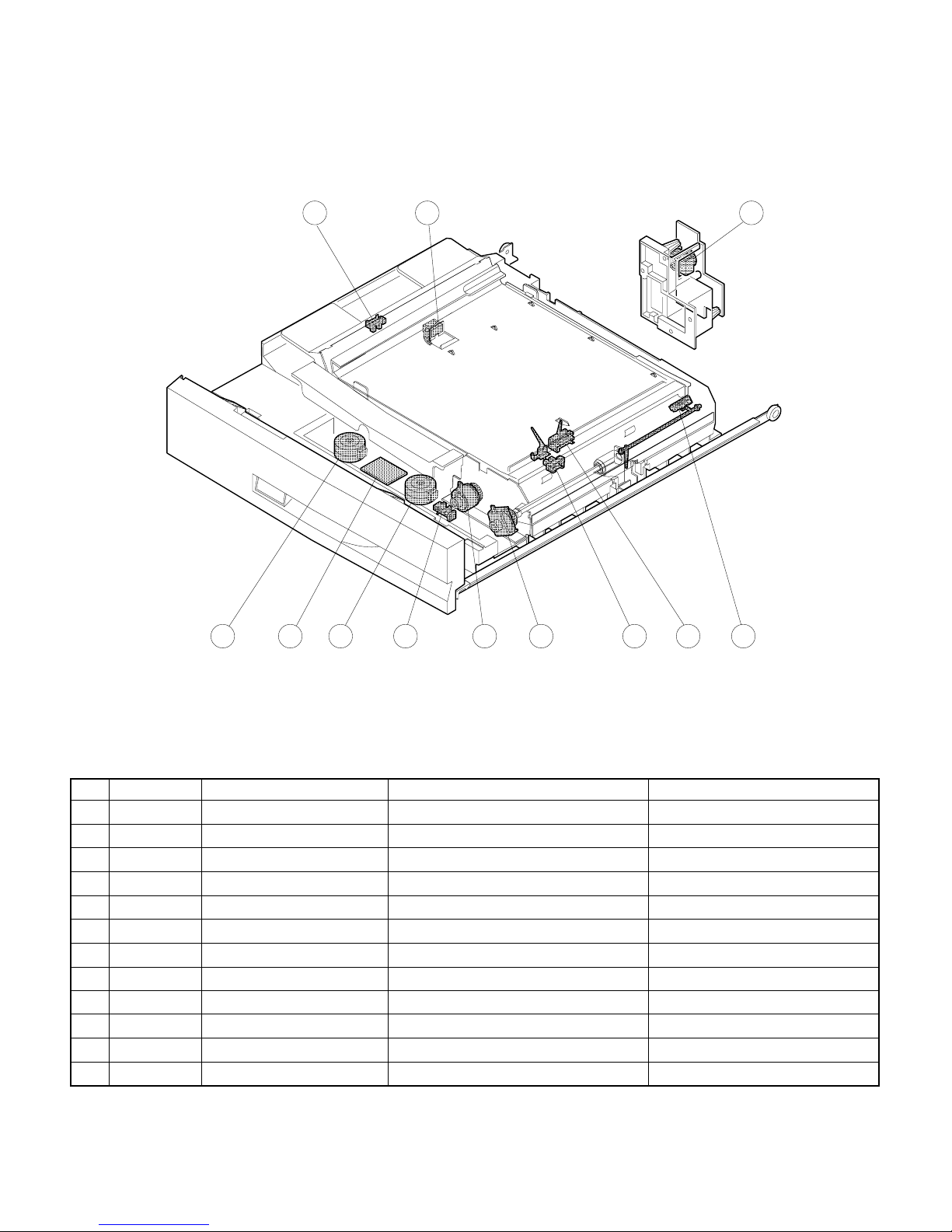
8. Duplex copy tray
1 2
12
87 9 10 5 4
11
3
6
Signal name Type Name Output
1
2
3
4
5
6
7
8
9
F
G
H
APHPS2 Transimissive photosensor ADU rear plate home position sensor Low when at home position
DPPD1 Transimissive photosensor ADU paper transport sensor-1 High when paper passes over
APHPS1 Transimissive photosensor ADU alignment plate home position sensor Low when over home position
DPPD2 Transimissive photosensor ADU paper transport sensor-2 High when paper detected
DTPID Transimissive photosensor ADU tray sensor High when paper detected
DPFD Transimissive photosensor ADU paper entry sensor High when paper detected
PAM2 DC stepping motor ADU rear plate motor
PAM1 DC stepping motor ADU alignment plate motor
DPFC Magnetic clutch ADU paper feed clutch
DRRC Magnetic clutch ADU counter roller clutch
DDC Magnetic clutch ADU clutch
ADUPWB Duplex copy tray load driving Diode PWB
4 – 9
Page 28
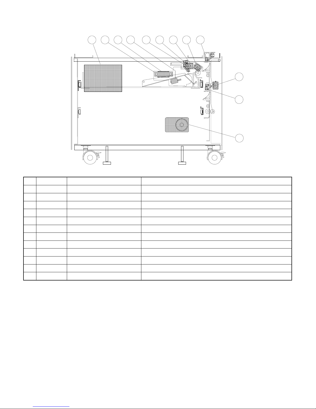
9. Desk unit (SF-D 20)
9 7 6 4
Signal name Name Function
1
2
3
4
5
6
7
8
9
F
G
H
DPOD1 Desk paper exit sensor Paper exit sensor (High when paper passes over)
DPOD2 Desk paper exit sensor Paper exit sensor (High when paper passes over)
DLUD1 Desk cassette liftup sensor Cassette liftup sensor (Low when lift plate detected)
DPED1 Desk cassette paper sensor Cassette paper sensor (Low when paper detected)
DLUM1 Desk cassette liftup motor Cassette liftup drive motor
— Liftup motor PWB —
— Cassette paper size PWB —
DM Desk drive motor Desk main motor
— Desk main PWB —
DTRC Desk transport roller clutch Transport roller drive
DPFC1 Desk paper feed clutch Paper feed roller drive
DPFS1 Desk paper feed solenoid Paper takeup roller drive
5 11
3 1
12
10
2
8
4 – 10
Page 29
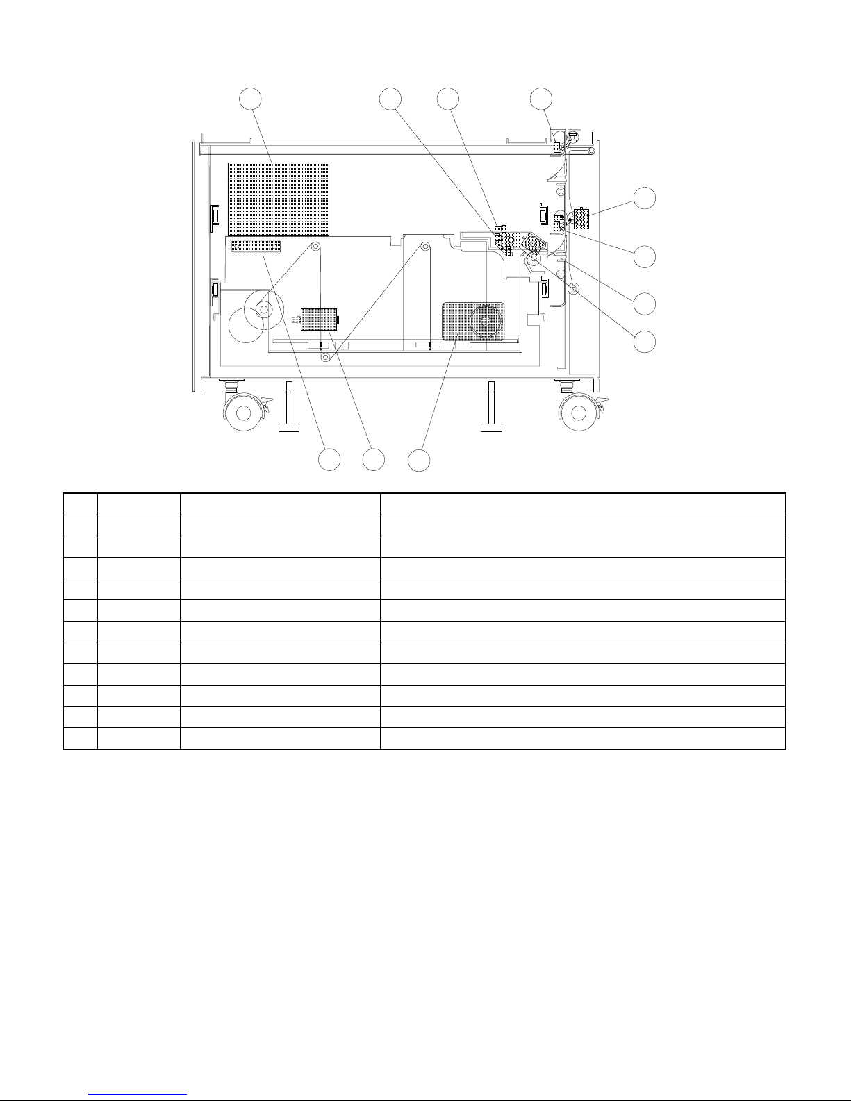
10. Desk unit (SF-D21)
7
4
3 1
8
2
9
10
5
11
6
Signal name Name Function
1
2
3
4
5
6
7
8
9
F
G
DPOD1 Desk paper exit sensor Paper exit sensor (High when paper passes over)
DPOD2 Desk paper exit sensor Paper exit sensor (High when paper passes over)
DLUD2 Desk cassette liftup sensor Cassette liftup sensor (Low when lift plate detected)
DPED2 Desk cassette paper sensor Cassette paper sensor (Low when paper detected)
— Cassette paper size PWB —
DM Desk drive motor Desk main motor
— Desk main PWB —
DTRC Desk transport roller clutch Transport roller drive
DPFC2 Desk paper feed clutch Paper feed roller drive
DPFS2 Desk paper feed solenoid Paper takeup roller drive
LCCM Large capacity cassette motor Cassette tray liftup drive motor
4 – 11
Page 30
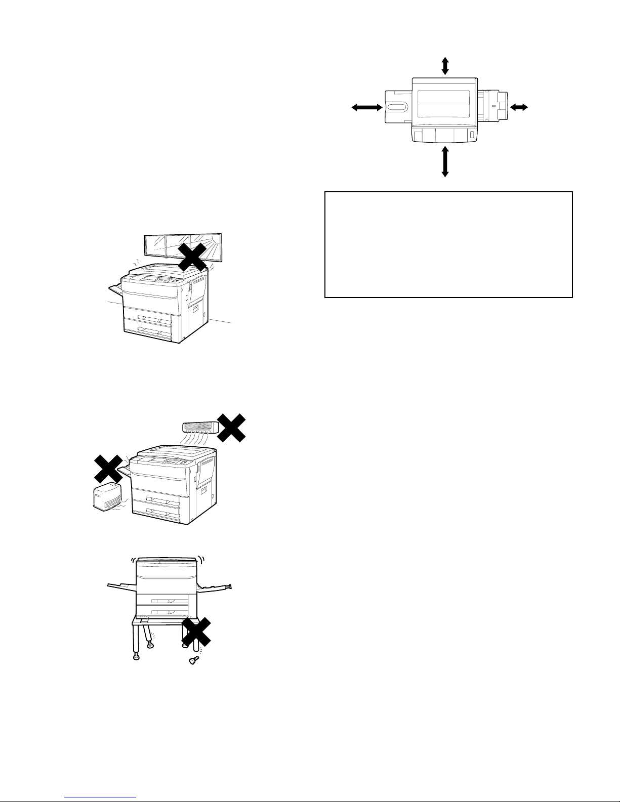
[5] INSTALLATION
A. Installing conditions
To ensure safety and proper machine performance, please note the
following before initial installation and whenever the machine is to be
relocated.
1. The copier should be installed near an accessible power outlet for
easy connection.
2. Be sure to connect the power cord only to a power outlet that
meets the specified voltage and current requirements.
Also make certain the outlet is properly grounded.
3. Do not install the machine where it is:
• damp or humid,
• exposed to direct sunlight,
5. Be sure to allow the required space around the machine for servicing and proper ventilation.
11-13/16"
(30cm)
12/8"
(60cm)
12/8"
(60cm)
A small amount of ozone is produced within the copier during
operation.
The emission level is insufficient to cause any health hazard.
NOTE:
The present recommended long term exposure limit for ozone is
0.1 ppm (0.2 mg/m3) calculated as an 8 hr. time-weighted average
concentration.
However, since the small amount that is emitted may have an
objectionable odor, it is advisable to place the copier in a
ventilated area.
00-13/16"
(30cm)
• extremely dusty,
• poorly ventilated,
• subject to extreme temperature or humidity changes (e.g., near
an air conditioner or heater).
4. Ensure that the area chosen for the machine location is level.
5 – 1
Page 31

B. Installation procedure
5 Hold the fuser unit hand carry strap and remove the fuser unit.
(1) SF-2030
1. Releasing optical locks
A. Removing the #2/3 mirror unit lock
Unfasten the screw that holds the #2/3 mirror unit on the left side of
the machine.
Mirror unit holding screw
B. Releasing the lens and #4/5 mirror unit from lock
Open the paper feed tray and remove two screws that hold the #4/5
mirror unit.
Close the manual tray.
Mirror unit holding screw
Hand hold st rap
Front panel band
Paper exit
Screws
Roller r otat i ng knob
Front panel
Fuser u nit
Locator pins
Ribs
B. Tensioning the heat roller
Move the tension levers on both sides of the fuser unit to the position
shown in the figure. With this, tension is applied to the upper and
lower heat rollers.
Paper feed tray
2. Fuser unit set up
A. Removing the fuser unit
1 While holding up the paper exit handle, open the paper exit cover.
2 Remove the front panel band on the left side of the front panel in
a manner shown in the figure.
Front panel band
1
2
Front sideRear side
Tension lever Tension lev er
C. Installing the cleaning roller
1 Remove the fusing cover fixing screws (2 pcs.), slide the fusing
cover towards you, and remove it.
Screws
Fuser cover
Fuser unit
3 Remove the fuser unit holding two screws.
4 Hold the fuser unit rotating knob. Push on the front panel and
gently remove the fuser unit.
Do not let the locator pins under the fuser unit hit the ribs on the
front cover.
5 – 2
Page 32
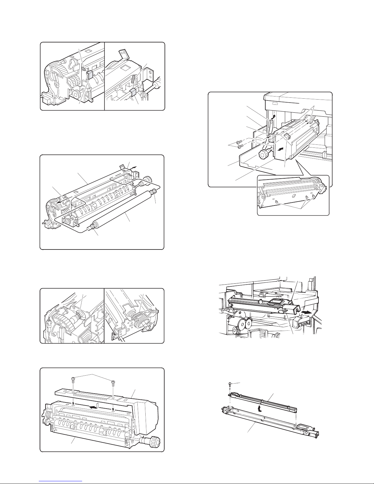
2 Remove the CL springs which are fixed to the front and the rear
side of the fusing unit with adhesive tape.
[Note] Slowly and surely remove the adhesive tape.
Rear
side
CL spring
Front
side
CL spring
D. Installing the fusing unit
Insert the locator pin under the fuser unit into slot. Gently push fuser
unit all the way in.
Make sure now that the locator pins of the copier are firmly engaged
into two locator holes of the fuser unit mounting bracket.
Secure fuser unit with two screw removed in 2 of A, and close the
paper exit.
Replace the front panel band that removed in 1 of A.
Close the paper exit cover.
CL spring fixing tapeCL spring fixing tape
3 Pass the cleaning roller through the round hole at the back of the
fusing unit, then insert the cleaning roller into the round hole at the
front.
Then position the bearings at the front and the back of the cleaning roller.
Front side round hole
Fuser unit
Rear side round hole
Busing
Cleaning roller
Busing
4 Hang the Cl springs on the front and the rear frames of the fusing
unit. (Shown with arrow ←.)
Be sure to check that the CL springs are pressing the bearings as
shown in the figure.
Rear side
.
CL spring
CL spring
.
Front panel band
Paper exit
Holding angle
Screws
Front panel
Fuser unit
Holding angle
Hand hold strap
Locator pins
3. Cleaning corona units
A. Clean the main corona unit
1 Push down the hook of the main corona unit while removing the
main corona unit from the copier.
Hook
5 Replace the fuser cover removed in Step 1, and fasten it with two
screws.
Screws
Fuser cover
Fuser unit
Front si de
Main corona unit
2 Unfasten the one screw holding the electrode on the back of the
main corona unit and remove the electrode.
Screw
Electrode
Main corona unit
5 – 3
Page 33
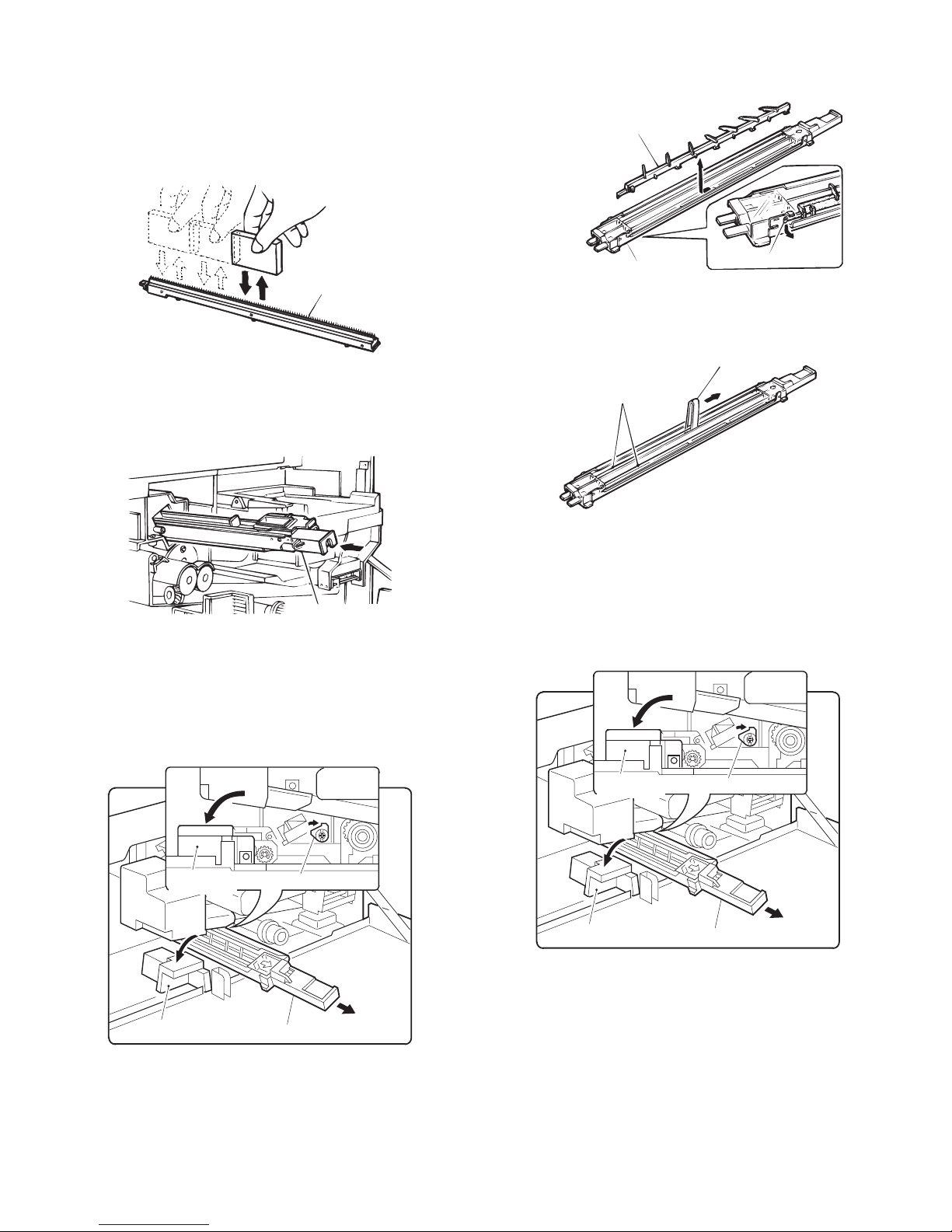
3 Very carefully clean the top of the electrode using the repeat this
procedure a few times.
NOTES:
• Never move the cleaner in any direction except up and down when
the cleaner is in contact with the electrode.
• Be sure to clean away the whole area evenly. Never clean only a
portion of the electrode.
2 Unhook the section A of the separation corona guide, slide the
separation corona in the direction of the arrow, and remove the
separation corona guide from the corona housing.
Separation corona wire guide
Electrode
4 Install the electrode and secure it with the one screw.
5 Insert the main corona unit all the way into machine. Guides must
be inserted into proper slots.
Main corona unit
B. Clean the transfer/separation corona wires
1 Tilt the paper transport block accessing lever to left. Rotate the
transfer corona lock plate clockwise using the scale or flat tip
screwdriver to release it from the lock. Remove the transfer/separation corona unit from the copier.
Corona wire housing
Section A
3 Squeeze the transfer/corona wire with the corona wire cleaner.
Move the cleaner in the direction of the arrow to clean the wire.
Corona wi re cl eaner
Corona wire
4 Install the separation corona guide to the corona housing. Insert
the corona assembly along the guide of the transfer/separation
corona unit.
Rotate the transfer corona lock plate counterclockwise, return the
paper transport block accessing lever clockwise, and close the
front panel.
Paper transport block
accessing lever
Paper transport block
accessing lever
Transfer corona lock plate
Transfer/separation corona unit
Paper transport block
accessing lever
Paper transp ort blo ck
accessing le ver
4. Installing accessories
A. Install the copy receive tray
5 – 4
Transfer corona lock plate
Transfer/separation corona unit
Page 34
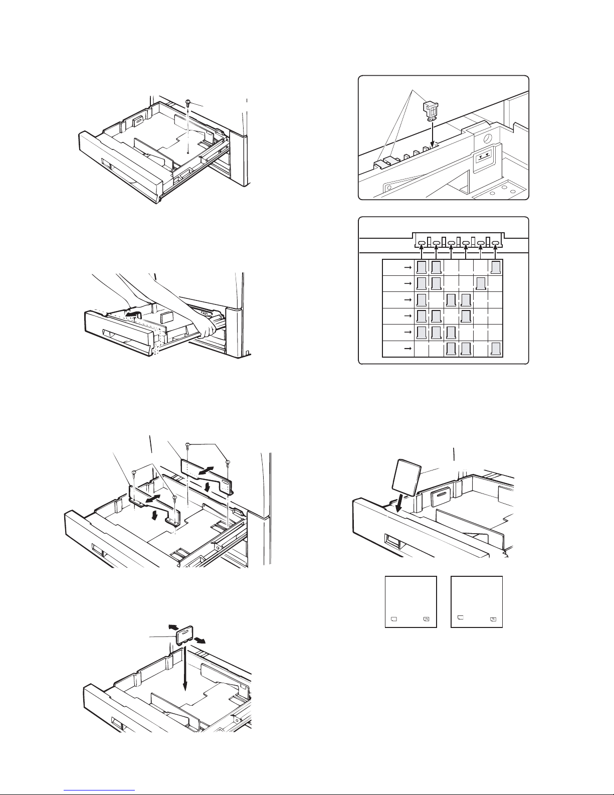
5. Setting up the upper paper cassette
A. Remove the packing screw of the cassette.
Pull out the cassette drawer by lifting while pulling out drawer.
Remove the one packing screw that secures the paper tension plate
of the cassette.
Packing scr ew
E. Set the size detect spacer
Change the position of the size detect spacer. Move the spacer to the
appropriate positions.
Size detec t s pac er
(Ex) A3 setting
In the case of the B5R cassette, it has been set at the factory.
B. Removing the cassette
Hold up the cassette grasping the both sides of the cassette and pull
it all the way out.
C. Change the size using the side plates F and R.
Remove two screws that hold the side plates F and R. Set the plates
into their position shown with notches, and secure with the two
screws.
Side pl at e R
Side pl at e F
Screws
Screws
Size detec t spac er set ti ng
A3
A4
A4R
B4
B5
B5R
F. Change the paper size indication plate
Remove the paper size indication plate. Install the plate so the size of
the paper can be seen from the window.
Paper sizes are printed on the front and the back of the paper size
indicator plate.
Paper size indication plate
D. Insert the rear plate
Remove the rear plate and set the plate into the position indicated for
the desired paper sixe.
Rear pla te
5 – 5
A4
(Front)
A3
A4
Special
B4
B5
B5
(Back)
Page 35

G. Set the cassette
Hold up both sides of the cassette from back and insert it along the
guide rails.
Ensure the cassette moves in and out smoothly.
Guide rail
Guide rail
B. Change the size using the side plates F and R. (set to
A3 position at the factory.)
Set the plates into the appropriate positions and secure wach plate
with two screws.
Side plate R
Screws
Screws
Guide
Guide
H. Load paper
Load paper in the cassette, but not above the maximum line.
Insert the cassette all the way into the machine.
Line in di ca ti on l ab el
6. Set up the lower paper cassette
A. Remove the packing screw of the cassette.
Remove the two packing screw that hold the paper tension plate of
the cassette.
Side pl at e F
C. Change the size of the rear plate.
Remove the rear plate. Set the plate into the position indicated for the
desired paper size.
Rear pl at e
D. Set the size detect spacer
Change the position of the size detect spacer. Move the size detect
spacers to the appropriate positions.
Size detec t s pac er
(Ex) A3 setting
Packing scr ew
Packing screw
Size detect spacer setting
A3
A4
A4R
B4
B5
B5R
5 – 6
Page 36

E. Change the paper size indication plate
Remove the pa pe r size in dicat ion plat e. Ins ta ll the pl ate s so the siz e
of the paper can be seen from the window.
Paper sizes are printed on the front and the back of the paper size
indicator plate.
Paper size indication plate
3 Slide the developing unit lock lever in the arrow direction to
release lock, and hold the toner box lever and pull out the
developing unit until it stops.
[Note]
• When lock is released and the developing unit becomes free to
move, let go of the developing unit lock lever.
Paper size i n di cat ion port
A3
B4
A4
A4
(Front)
Special
B5
B5
(Back)
F. Setting paper
Set paper on the cassette. Do not load so much paper that exceeds
the indication line.
Insert the cassette completely into the copier body.
Indicat ion l abel li ne
Developing unit lock leverToner box lever
4 Hold the carry strap of the developing unit and slide the develop-
ing unit lock lever in the arrow direction to release lock. Then
remove the developing unit.
Carry strap
Developing unit loc k lever
5 Remove the lens fixing screw (1 pc.) under the operation panel.
7. Lens lock release
A. Removing the lens and releasing the lens lock
1 Open the front cabinet.
2 Tilt down the toner box lever and pull out the toner box until it
stops.
Toner box lever
Lens fixing screw
5 – 7
Page 37

8. Setting the developing unit
A. Supplying developer
1 Remove the 5P connector which is connecting the toner hopper
and the developing unit.
Remove the five toner hopper fixing screws (silver 3 pcs., blue 2
pcs.) of the developing unit, and remove the toner hopper.
Fixing screw (silver)
Fixing screws (silver)
Toner hopper
Fixing screws (bl ue)
Fixing screw
(blue)
9. Toner density sensor level adjustment
Turn on the power switch of the copier body.
A. Developing unit level adjustment
1 Perform the key operations of simulation 25.
C
Interruption Interruption
2 Simulation 25 will be completed in 3 minutes.
(Note) If the simulation is cancelled halfway, auto scanning can-
not be performed. Do not cancel it halfway.
3 Cancel simulation 25 with the [CA] key.
0 /
Copy
2
2
5
Copy
5P connector
Developing unit
2 While supplying developer from the developer supply port of the
developing unit, turn the MG gear clockwise with a screwdriver (+)
or a scale to completely supply developer into the developing unit.
Developer
Developer supply port
Developing unit
MG gear
3 Install the toner hopper to the developing unit, and fix it with the
five screws (silver 3pcs., blue 2 pcs.). Connect the 5P connecter
of the developing unit with the toner hopper.
Fixing screw (silver)
Fixing screw (blue)
Fixing screw
(blue)
10. Toner supply
A. Toner supply
1 Open the front cabinet.
2 Tilt down the toner box lever towards you and pull out the toner
box until it stops.
Toner box lever
3 Shake the toner cartridge up and down about 20 times.
Fixing screw (silver)
Toner hopper
Developing uni t
4 Install the toner cartridge to the toner box as shown in the figure
below.
5P connector
5 – 8
Page 38

5 Move the toner cartridge in the arrow direction until it stops.
9 Push the toner box slowly to the original position, and lift the toner
box lever.
Toner box lever
6 While holding the toner cartridge, pull the seal to supply toner.
[Note]
• It takes about 30 minutes to finish supplying toner.
7 Tap the top of the toner cartridge to put down toner attached
inside the toner cartridge.
Toner supply is completed with the above procedure. Close the front
cabinet.
11. Label attachment
A. Label attachment
Attach the magnification ratio select label packed together with the
Operation Manual to the position shown below.
• When attaching to the copier with the original cover:
Magnification ratio select label
8 Move the empty toner cartridge in the arrow direction to remove.
• When attaching to the auto document feeder:
magnification ratio select label
5 – 9
Page 39

(2) SF-A17/56 Unplug the copier and follow the procedure below.
1. Remove the document cover.
Open the document cover and lift it at a slight backward angle to
remove it.
Insert the left and right covers (included parts) into the holes from
which the document cover has been removed.
SF-A56
Document cover
Right cover
SF-A17
Included parts
ADF mounting screws
(2 pcs.)
ADF tray
ADF securing screws
(2 pcs.)
Right cover
(1 pc.)
Left cover
2. Mount the ADF onto the copier.
Remove the two cut-outs from the rear part of the upper cover of the
copier.
Cut-outs
Rear part of
upper cover
Tray securing screws
(2 pcs.)
Left cover
(1 pc.)
Install the two ADF mounting screws.
ADF mounting screws
5 – 10
Page 40
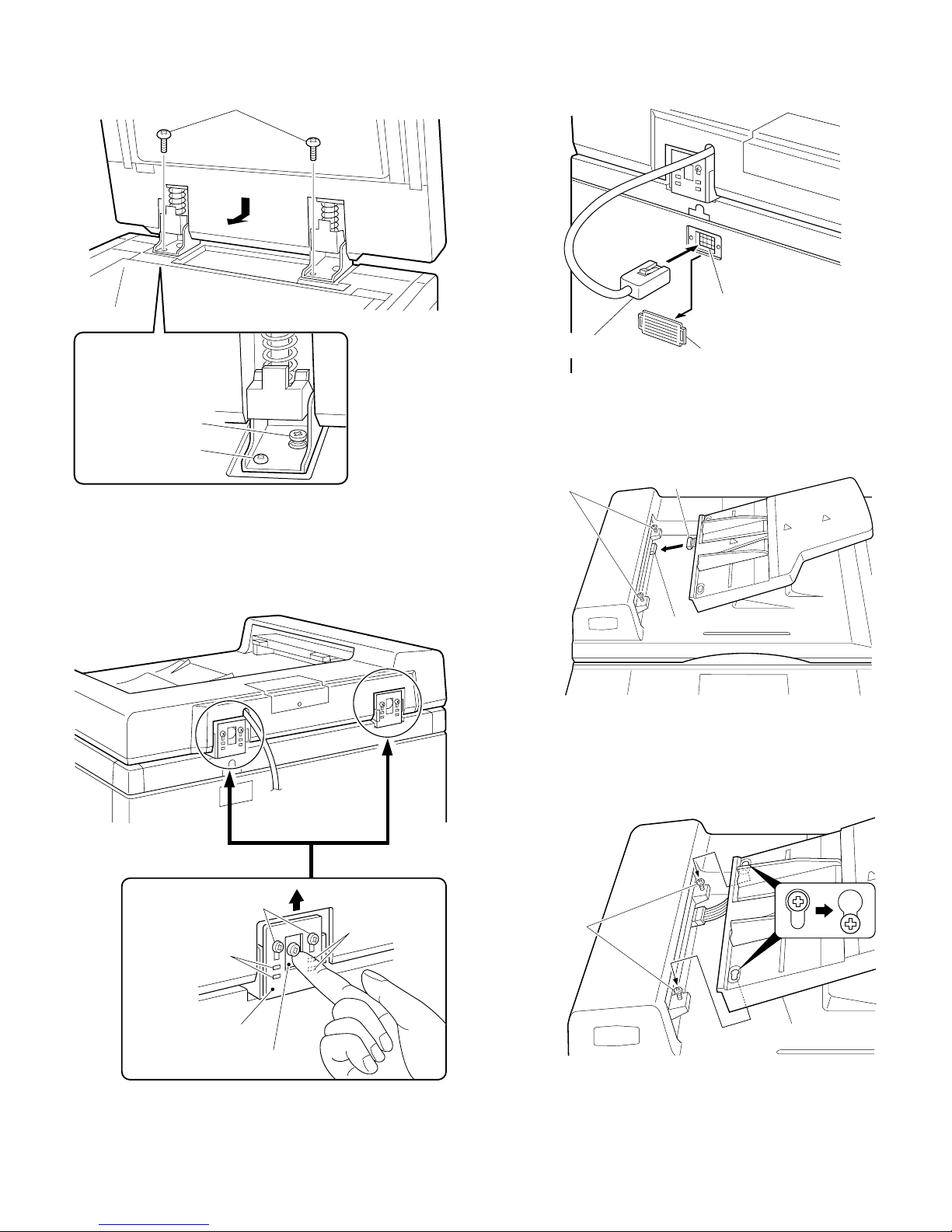
Fit the ADF mounting screws into the holes in the hinges of the ADF
and secure the ADF with the two ADF securing screws.
ADF securing screws
4. Connect the ADF connector.
Remove the connector cover from the copier’s rear cover.
Next, connect the ADF connector to the connector on the copier.
Connector on the copier
ADF mounting screw
ADF securing screw
3. Adjust the angle of ADF.
Loosen the two securing screws for the angle adjusting panel attached to the hinge angle and then fasten the loosened screws while
raising the angle adjusting panel completely.
ADF connector
Connector cover
5. Connect the ADF tray connector.
Thread the M4 x 8 tray securing screws (includedparts) partway into
their holes, then connect thetray connector.
Tray securing screws
Tray connector
Connector on the ADF
6. Attach the ADF tray.
Loosen the two ADF tray securing screws, install the tray as shown in
the figure, and fasten the tray securing screws.
Angle adjusting panel
securing screws
Long hole
Hinge
Angle adjusting panel
NOTE: Be sure to check that the protrusion of the angle adjusting
panel is securely inserted into the long hole of the hinge.
Long hole
Tray securing
screws
Tray
5 – 11
Page 41
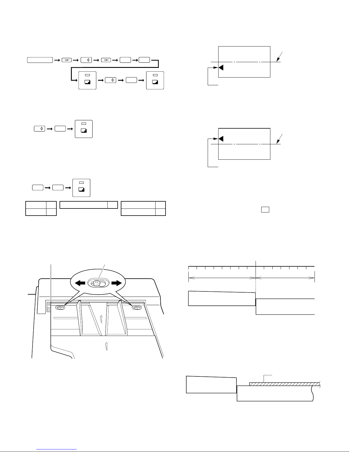
Plug the copier into a grounded outlet and turn the
power switch on. Then, follow the procedure below.
7. Set the mode.
• Operate the copier keys to set the mode.
★ When off center as shown in fig. 1
Move the tray in direction A and secure it with the two mounting
screws. Make a copy to check whether it is centered properly.
Fig. 1
Center of copy paper
C
0/
2
0/
The above key operation will display the currently set mode.
6
1
• When only the SF-A56 is to be set, immediately after the above
key operation, operate the keys as follows:
0/
1
• If the mode is to be set in combination with other options, use the
table shown below to add up the total of the setting values for all
the peripheral devices to be set, and set that total value.
For example, if the SF-A56 and sorter are to be set, the total
setting value is 1 + 10 = 11. Operate the keys as follows:
1
SF-A17 1 Stand/paper drawer 4 Sorter 10
SF-A56 1 Staple sorter 10
1
8. Adjust the center of the copy.
Set an original in the ADF tray and make a copy.
When the copy is off center as shown in Fig. 1 or Fig. 2, loosen the
two tray securing screws and adjust the tray by moving it in direction
A orB as shown in the figure.
Mark Tray securing screw
Center of original image (first copy)
★ When off center as shown in fig. 2
Move the tray in direction B and secure it with the two mounting
screws. Make a copy to check whether it is centered properly.
Fig. 2
Center of copy paper
Center of original image (first copy)
9. Adjust the position of the leading edge of
originals
• The position of the leading edge of originals fed from the ADF can
be determined using test command 53 .
• Although the leading edge has been factory set to stop at location
(8), it may need to be adjusted depending on the type of originals.
The leading edge position can be adjusted within a range of 8 mm
(8 steps) on the stopper side and 7 mm (7 steps) on the glass side
in 1 mm increments. Adjustment can be done separately for the
one-sided, two-sided, and thin paper modes.
8
0 101112131415234567 91
BA
8mm
Stopper
View from the operator side
7mm
Glass
Setup example
(1) If the leading edge of the original was not fed all the way to the
stoppe r, enter value which will mo ve the original towa rd the
stopper side.
7, 6, 5, 4...
Original
Stopper
Glass
5 – 12
Page 42

(2) If the copy image at the leading edge was distorted, enter value
which will move the original toward the glass side.
9, 10, 11...
Original
Stopper
Glass
(3) If the original overrode the stopper, enter value which will move
the original toward the glass side.
9, 10, 11, 12 ...
Original
Included parts
Caster screws
(M4 x 50): 8
Sorter m ount ing plat e screw s
(M4 x 12): 2
Rail screws A
(M4 x 6): 2
Rail screws B
(M4 x 6): 1
Rail mounting plate screws
(M4 x 14): 2
Stopper
Glass
• After selecting test command 53 , enter a selected set value
between 0 and 15 using the copier keys.
0/
0/
(a)
1
(b)
2
C
(a) One-sided mode
(b) Two-sided mode
★
For SF-A17, only (a) is possible.
Set to between 0 and 15 as dictated by the copier's performance.
The factory setting is "8".
5
3
(3) SF-S53
Bracket screws
(M4 x 10): 2
Caster spacers: 4
Rail: 1
Sorter mounting plate: 1
Rail mounting plate: 1
Green label: 1
Support gui de: 1
Sorter protection mat: 1
Stapli ng l oc at ion labe l A: 1 Stapling lo c at io n l abe l D: 1
5 – 13
Page 43
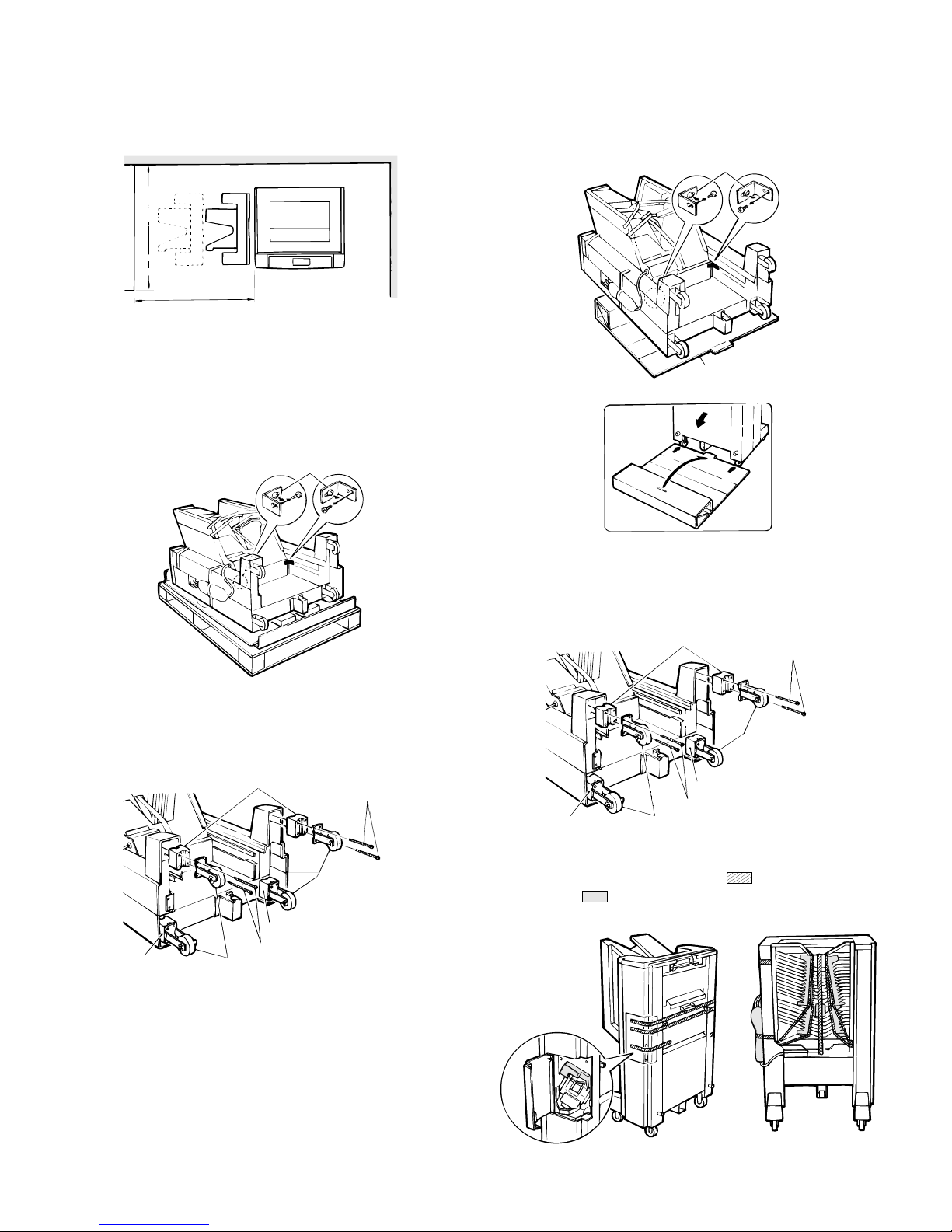
Before installing
Be sure that you have plenty of room around the
copier for work space.
1.5m
1.0m
★ When not performed on the skid
Open the sorter protection mat, as shown in the figure, and position it
against the sorter’s casters. Lay the sorter down on the protection
mat.
Next, remove the securing fixtures (2).
Securing fixtures
Remove the securing fixtures and attach the caster
spacers.
★ When performed on the skid.
Remove the securing fixtures (2).
Securing fi xt ures
Remove the caster screws (2 per caster) and take off the 4 casters.
Next, attach the casters and caster spacers using 2 screws each (M4
x 50) as shown in the figure.
Caster spacer s
Caster screws
Sorter protect i on mat
3
2
1
2
Remove the caster screws (2 per caster) and take off the 4 casters.
Next, attach the casters and caster spacers using 2 screws each (M4
x 50) as shown in the figure.
Caster spacer s
Caster spacer
Caster screws
CastersCaster spacer
Caster screws
Casters
Casters
Caster spacer
Caster spacer
Caster screws
Casters
Remove all the securing tape ( ) and securing
materials ( ) shown in th e fig ures b e low .
5 – 14
Page 44

Unplug the copier’s power cord before carrying out
the following procedure.
A. Mounting of the staple sorter onto the copier.
1. Attach the sorter mounting plate.
Remove the screws (2) from the copier’s upper left cabinet panel.
Attach the sorter mounting plate with the 2 sorter mounting plate
screws (M4 x 12).
The sorter mounting plate screw holes are elongated; tighten the
screws so that the sorter mounting plate hangs down in its lowest
position.
Upper left cabi net panel sc r ews
4. Attach the rail to the sorter.
Insert the rail into the rail mounting anchor, on the bottom of the
sorter, and attach them with the 2 rail screws A (M4 x 6) and 1 rail
screw B (M4 x 6).
Rail mounting anchor
Sorter mounting
plate screws
Sorter mounti ng
plate
2. Attach the support guide.
Attach the support guide by attaching its pawls (2 locations) to the
inside of the copier’s paper output section.
Pawls
Support gui de
Rail
Rail screws A
Rail screws B
5. Fit the rail mounting plate onto the rail.
Insert the rail between the rollers on the rail mounting plate as shown
in the figure.
Rollers
Rail mounting plate
Rollers
Rail
6. Attach the rail mounting plate to the copier desk.
Slide the rail, which was just attached to the sorter, under the copier
as shown in the figure. Attach the rail mounting plate to the copier
with the 2 rail mounting plate screws (M4 x 14).
Desk
3. Cut off the cut portions of the desk’s left cabinet
panel.
Cut off the 2 cut portions of the desk’s left cabinet panel.
Cut port i ons
Desk
Rail mounting plate
Rail mo untin g p late screws
Rail
5 – 15
Page 45

7. Confirm that the staple sorter can be attached
and detached correctly.
1 Latch and unlatch the staple sorter from the copier to confirm that
it moves smoothly.
2 Confirm that the staple sorter locks into place beside the copier.
If not, adjust the height of the sorter mounting plate until the staple
sorter locks securely into place.
10. Reattach the rear cabinet panel.
Reattach the rear cabinet panel in its original position with the 4
mounting screws.
Mounti ng
screws
Rear c abinet
panel
Mounting screws
Soter mounti ng plate
8. Remove the copier’s rear cabinet panel and cut
off the cut portion of the left cabinet.
Remove the 4 screws securing the copier’s rear cabinet panel and
take the panel off.
Next, cut off the cut portion (1 location) of the left cabinet panel.
Mounti ng
screws
Rear c abinet
panel
Mounting s crew s
Notch
9. Attach the sorter connectors.
Loosely screw in 1 of the 2 supplied bracket screws as shown in the
figure. Hook the bracket in place over this screw, then insert the
remaining bracket screw and tighten both screws securely.
Next, connect the sorter’s 6-pin and 10-pin connectors to the copier’s
6-pin and 10-pin connectors. Then insert the clasp of the tie band into
the hole on the bottom of the installation board.
Bracket
mounting
screws
Bracket mounting
screws
11. Affix the stapling location labels.
Affix the stapling location labels to the copier and RADF (SF-A54) as
shown in the figure.
★ Copier
★ RADF (SF-A17/56)
Tie band
6-pin connector
10-pin connector
Bracket
5 – 16
Page 46

12. Affix the green label.
Lifting up on the staple sorter’s release lever, separate the sorter from
the copier.
Next, affix the green label to the paper output section handle as
shown in the figure.
Holding the staple sorter’s release lever, return the sorter to its
original position. At this time, confirm that the staple sorter locks
securely into place beside the copier.
Green label
Staple sorter
Paper output secti on handle
Plug the copier’s power cord into an electric outlet,
switch on the power, and then perform the
following procedure.
B. Staple sorter operation check
1. Check the sort mode.
Make 20 copies in the sort mode and confirm that the copies are
distributed to the sort bins with no abnormal noises from the sorter.
2. Check the non-sort mode.
Make copies in the non-sort mode and confirm that they are sent to
the non-sort bin.
3. Use the ADF (automatic document feeder) and
check the staple sort mode.
Place 2 or more sheets in the ADF and make copies in the staple sort
mode. Confirm that the copies are distributed to the sort bins, that the
staple guide bar arranges the copies and that the stapler functions
properly.
If at this time the copies have not been stapled or the stapler is
jammed, adjust the staples by performing one of the following procedures.
If copies have not been stapled
1. Remove the staple cartridge.
Open the stapler cover, lift up on the staple cartridge and remove it
by pulling in the direction of the arrow.
13. Set the mode.
• Perform the following key operations on the copier to set the
mode.
C
Performing the above operation will cause the current setting to
be displayed.
0 /
6
2
0 /
1
• If only the SF-S53 is being set, continue by performing the follow-
ing key operation to complete the mode setting.
0 /1
• If the mode is being set for a combination of options, add up the
numerical values of the options to be set (see the table below) and
input the total sum.
Example: When setting SF-S53 and SF-A17/56, the total sum of
their values is 11 (1 + 10). Therefore, perform the following key operations.
Staple cartridge
Stapler cover
2. Check the staple cartridge.
Confirm that the sheets of staples in the cartridge are properly stacked.
If not, slide the staples back in the direction of the arrow while pressing in gently on the bottom of the cartridge.
11
SF-A17/56 1 SF-D20 4 Sorter 10
SF-D21H 4
5 – 17
Page 47

3. Reinsert the staple cartridge.
Push the staple cartridge in horizontally until it clicks securely into
place.
Then close the stapler cover.
Staple cartridge
Stapler c over
4. Confirm that papers are stapled correctly.
Place a set of papers in the 2nd bin (below the non-sort bin), check
the stapling location, and then press the manual staple key when it
lights up.
Next, remove the papers that were placed in the 2nd bin and confirm
that they have been stapled correctly.
At this time, if the papers still have not been stapled, repeat this
procedure once again.
2. Open the stapling section.
Open the stapling section by pushing up on the stapling plate while
pressing on the stapling section release lever.
Stapling s ecti on rel ease l ev er
Stapling plate
3. Remove the jammed staples.
Remove the jammed staples with the supplied tool as shown in the
figure.
* This tool can be found on the inside of the staple unit cover.
Copy papers
Stapling l ocation
Copy papers
Copier
This completes the staple sorter installation.
If staples have become jammed.
1. Remove the stapler unit.
Open the stapler cover and remove the mounting screw securing the
unit in place.
Next, remove the staple unit.
Tool
4. Close the stapling section.
Press down on the stapling plate and return it to its original position.
Next, return the stapling section release lever to its original position.
Stapling plate
Stapling section
release lever
5. Reinstall the staple unit.
Reinstall the staple unit in its original location using the mounting
screw to secure it in place.
Then close the stapler cover.
Staple unit
5 – 18
Staple cover
Mounting s c rew
Page 48
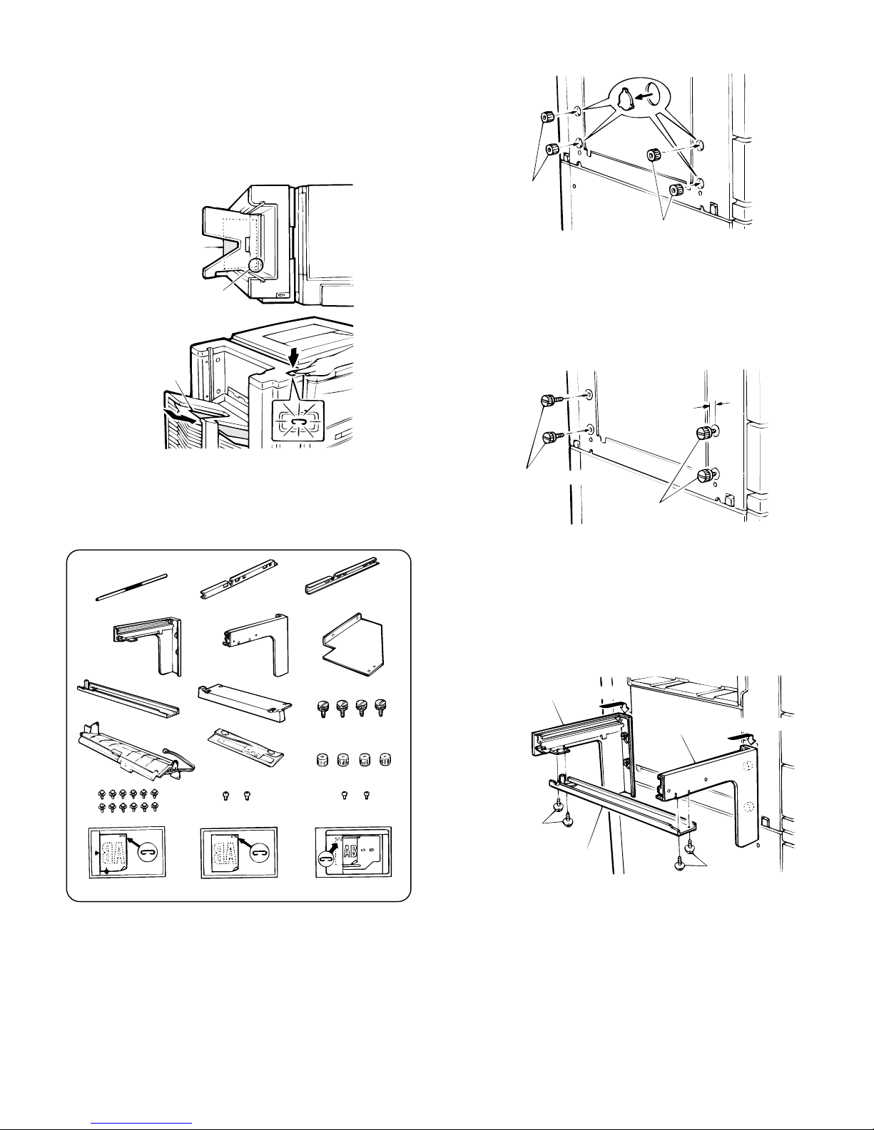
6. Confirm that papers are stapled correctly.
Place a set of papers in the 2nd bin (below the non-sort bin), check
the stapling location, and then press the manual staple key when it
lights up.
Next, remove the papers that were placed in the 2nd bin and confirm
that they have been stapled correctly.
At this time, if the papers still have not been stapled, repeat this
procedure once again.
a. After unpacking, check that all the parts are provided as follows:
Cut-outs i n t he ca binet p anel
Spacers
Copy papers
Copier
Stapl ing location
Copy papers
This completes the staple sorter installation.
(4) SF-S52
Parts list
Handle (1 pc.)
Sorter m o un t i n g
angle, rear (1 pc.)
Connecting pl ate
(1 pc.)
Handle suppor t plate,
front (1 pc.)
Sorter mounting
angle, f r o nt ( 1 pc. )
Cover (1 pc.)
Handle suppor t plate,
rear (1 pc.)
Support plate (1pc.)
Sorter mounting angle
screws (4 pcs.)
Spacers
b. Disconnect the power plug of the copier body.
c. Remove the cut-outs in the cabinet panel at the spacer holes on
the left side of the copier and fit the sorter mounting angle spacers
into the holes.
d. Attach the sorter mounting angle screws (4 pcs). Allow a space of
2 - 3 mm between the screws and the spacers.
2~3mm
Sorter mounting
angle sc r ew s
Sorter mounting
angle sc r ew s
e. Attach the sorter mounting angle and the connecting plate.
• Hook the front and rear sorter mounting angles into the spaces
between the sorter mounting angle screws and the spacers,
and tighten the four sorter mounting angle screws.
• Next, use the four connecting plate mounting screws to secure
the connecting plate to the front and rear sorter mounting
angles.
Sorter moun ti ng angl e, rear
Sorter mount ing an gl e, front
Paper guide
(1 pc.)
Mounting screws (12 pcs.)
Staple position indicat ing
label for the copier
Maintenance pouch
(1 pc.)
Paper guide mounting
screws (2 pcs .)
Staple position indicat ing
label for t he ADF
Spacers (4 pcs .)
Brack et m ount ing scre ws
(2 pcs.)
Staple positio n indicat ing
label for the RA DF
5 – 19
Mounting
screws
Connecti ng pla te
Mounting
screws
Page 49

• Attach the support plate to the sorter mounting angle R and the
connecting plate, and fix it with four fixing screws.
h. Install the rear cabinet panel to the sorter.
Tighten the 4 mounting screws to install the rear cabinet panel.
Sorter moun ti ng angl e, rear
Mounting
screws
f. Remove the rear cabinet panel from the sorter.
Loosen the 4 screws securing the rear cabinet panel to the sorter,
then remove the rear cabinet panel.
Support pla te
Rear cab inet pan el
Mounting
screws
Rear cab inet pan el
Mounting
screws
Mounting
screws
i. Mount the sorter onto the copier.
• Fit the guide plate on the sorter body into the guides on the
front and rear sorter mounting angles.
Mounting
screws
Mounting
screws
g. Mount the paper guide.
1 Insert the paper guide harness through the hole, and use the 2
mounting screws to attach the paper guide.
2 Connect the 3-pin connector of the paper guide harness to the
3-pin connector of the sorter control base.
Rear cab inet pan el
Mounting
screws
Guide plates
j. Attach the handle to the sorter.
Attach the handle mounting plates F and R to the sorter shaft as
shown in the figure, and fix it with two fixing screws.
Then attach the handle to the handle mounting plates F and R
and fix it with two fixing screws.
Handle suppor t plate, front
Handle
Mounting
screw
Handle support
plate, r ear
Mounting screw
Mounting
screws
5 – 20
Shaft
Mounti ng screw
Mounti ng screw
Page 50
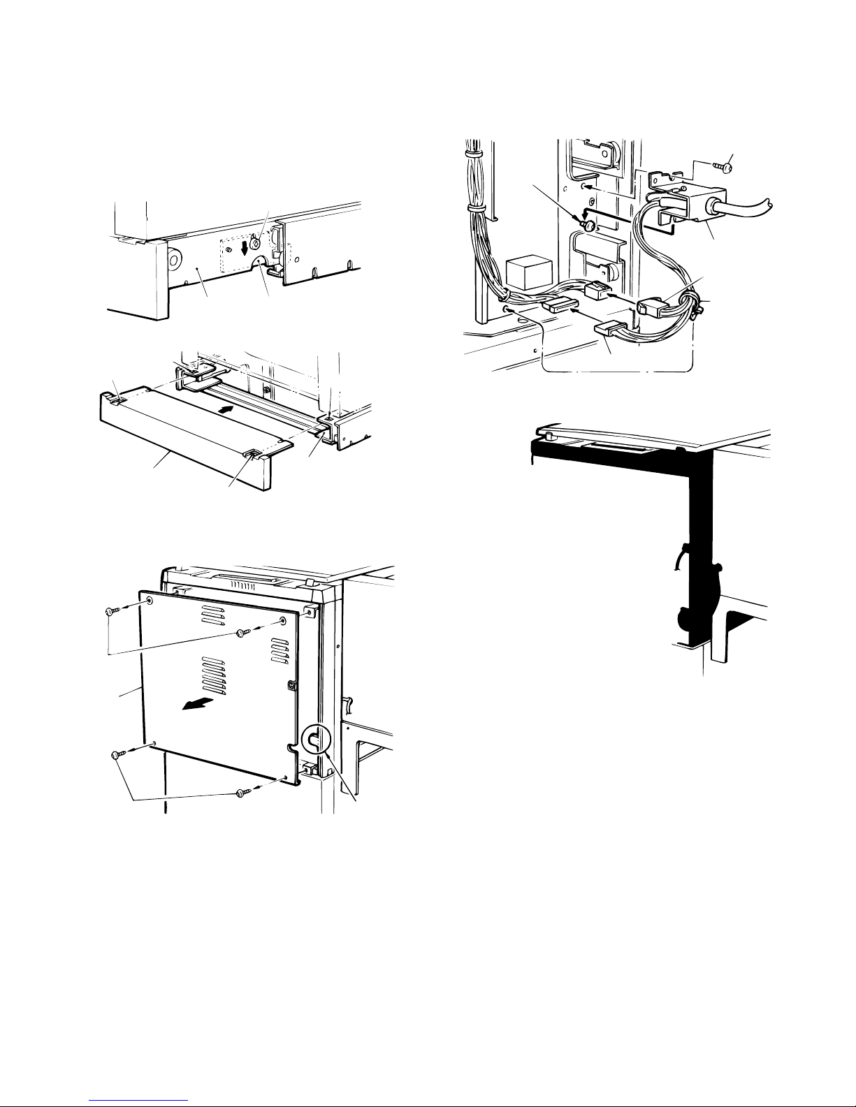
k. Lock the sorter body.
1 Pull out the sorter body slowly until the black screw on the
guide plate can be seen.
2 Loosen the black screws (one in the front, one in the rear)
fixing the stopper plates (one in the front, one in the rear), and
lower the stopper plates all the way, then tighten the black
screws.
3 Insert the pawls in the cover into the square holes in the guide
plates, and attach the cover.
Black screw
m. Connect the sorter connector.
1 Use the two bracket mounting screws to secure the bracket.
2 Connect the 6-pin connector and the 10-pin connector of the
sorter to the 6-pin connector and the 10-pin connector of the
copier.
Brac ket
mounting
screw
Bracket mounting screw
Bracket
6-pin c o nn ect or
Guide plate
Square hole
Pawl
Cover
Pawl
l. Remove the rear cabinet panel from the copier and cut out the
notch in the cabinet panel.
Mounting
screws
Rear cabi net
panel
Stopper p l at e
Square hole
Guide plate
Tie band
10-pin connector
n. Attach the rear cabinet panel with four screws.
o. Set the mode.
1 The following key operation will display the current set value.
TabMounting sc rews
operation, operate the keys as follows:
2 If only the SF-S52 is to be set, immediately after the above key
Page 51

3 If the mode is to be set for a combination with other options,
add up the total of the setting values for all the peripheral
devices to be set from the table shown below, and set the total
value.
<Example> If the SF-S52 and the SF-A17/A56 are to be set,
the total setting value is 10 + 1 = 11. Operate the
keys as follows:
Set values of peripheral devices
SF-A17/A56 1 SF-D20 4 Sorter 10
SD-D21 4
p. Affix the staple position indicating label to the copier and the ADF
(SF-A17) or the RADF (SF-A56) as shown in the figure.
• Copier
• ADF (SF-A17)
• RADF (SF-A56)
Maintenance pouch
Top cover
Check the staple sorter.
a. SORT mode
Make 20 copies in the SORT mode. Make sure all copies are
properly sorted to the sort bins and also check for any unusual
operating noises.
b. NON-SORT mode
Make copies in the NON-SORT mode. Make sure that all copies
go to the top bin.
c. STAPLE SORT mode
Set more than 2 originals in the ADF and make copies in the
STAPLE SORT mode. Make sure all copy papers are properly
sorted to the bins and are properly stapled.
Note: When copies are not stapled or when a staple jam occurs,
refer to "d. When copies are not stapled" or "e. When a
staple jam occurs."
d. When copies are not stapled:
1 Open the sorter top cover, raise the stapler handle up and pull
out the stapler.
q. Attach the maintenance pouch.
• Open the sorter top cover and attach the enclosed main-
tenance pouch containing tool A and tool B onto the frame of
the staple sorter.
Tool A Tool B
2 Raise the retaining lever and remove the staple cartridge from
the stapler.
Retaining lever
Staple cartridge
5 – 22
Page 52
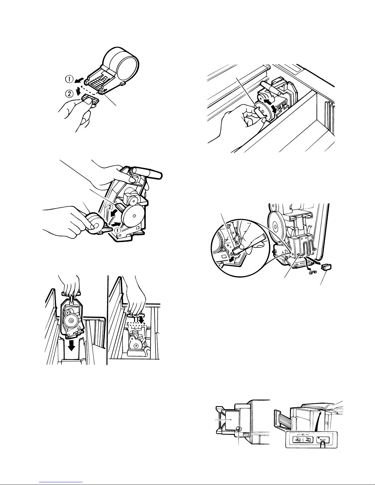
3 Check that the first staple in the staple cartridge is at the
indication line. If not, pull it to the indication line. If any staples
are protruding past the indication line, tear them off at the
indication line.
Indication line
4 Install the staple cartridge in place. Lower the retaining lever to
secure the staple cartridge.
Retaining lever
Staple cartridge
e. When a staple jam occurs:
1 Open the top cover, raise the stapler handle up and pull out
the stapler.
If the stapler is difficult to remove because of misfed paper,
insert tool A in the maintenance pouch into the wheel of the
stapler, then turn in either direction to ease stapler removal.
Tool A
2 Raise the retaining lever and remove the staple cartridge from
the stapler.
3 Using tool B in the maintenance pouch, remove the retaining
clip at the stapling position, remove the block at the tip, then
remove the jammed staple.
5 Align the stapler with the groove and position it in place.
Lower the stapler handle back down as shown.
Close the sorter top cover.
Tool B
Retaining clip
Block
4 Replace the block and the retaining clip to their original posi-
tions.
5 Place the staple cartridge back into position.
Lower the retaining lever to secure the staple cartridge.
6 Align the stapler with the groove and position it in place.
Lower the stapler handle back down as shown.
Close the top cover.
f. Make sure the copies are stapled.
1 Place a set of copies on the top bin and make sure of the
correct staple position. Press the manual staple key.
2 Remove the copies from the top bin and check to be sure the
stapler works properly.
Note: If they are not stapled, repeat this procedure.
5 – 23
Copie s
Copier
Stapling pos iti on
Page 53

(5) SF-S18
Included parts
Support guide
(1 pc.)
Sorter seat cover securing screws
Sorter seat securing screws
(4 pcs.)
Spacers
(4 pcs.)
(3 pcs.)
Stopper screw
Lockplate screws (M4 x 8)
(2 pcs.)
Sorter securing screws (M4 x 8)
(2 pcs.)
Felt washer
(1 pc.)
(1 pc.)
Unplug the copier and follow the procedure below.
1. Mount the lock plate.
Remove the screws (2) from the upper side of the copier’s left cabinet
panel.
Mount the lock plate to the upper side of the copier’s left cabinet
panel and secure it with the M4 x 8 lockplate screws (2).
Upper left cabinet panel screws
Lock plate
(1 pc.)
Sorter seat
(1 pc.)
Sorter seat cover
(1 pc.)
Lock plate
Lock plate screws
2. Mount the support guide.
Hang the two hooks of the support guide on the exit area of the
copier to mount the support guide.
Hooks
Support guide
5 – 24
Page 54

3. Remove the cut-outs.
Remove the four cut-outs from the left cabinet panel of the copier.
Cut-outs
4. Insert the spacers.
Insert the four spacers into the holes which have been made by
removing the cut-outs in step 3.
6. Mount the sorter seat cover.
Mount the sorter seat cover to the sorter seat and secure it using
three sorter seat cover securing screws.
Sorter seat cover securing screws
Sorter seat cover
7. Mount the sorter.
Insert the shaft on the back of the sorter seat between the rollers at
the back of the sorter.
Back side
Spacers
Spacers
5. Mount the sorter seat.
Temporarily secure the sorter seat securing screws to the two upper
spacers which have been mounted in step 4.
Insert these two sorter seat securing screws into the two upper holes
of the sorter seat as shown in the figure.
Secure the lower part of the sorter seat by inserting the two sorter
seat securing screws into the lower two holes of the sorter seat and
tighten the temporarily secured upper screws to secure the sorter
seat.
Sorter seat securing screws
Rollers
Sorter
Sorter seat shaft
Next, insert the slide rail on the front of the sorter seat into the slide
rail mount on the front of the sorter and push the sorter in place.
Front side
Slide rail mount
Sorter
Sorter seat securing screws
Sorter seat
Sorter seat slide rail
NOTE: Be sure to slide the sorter away from the copier and check
that the sorter is not removed from the slide rail of the sorter
seat.
5 – 25
Page 55
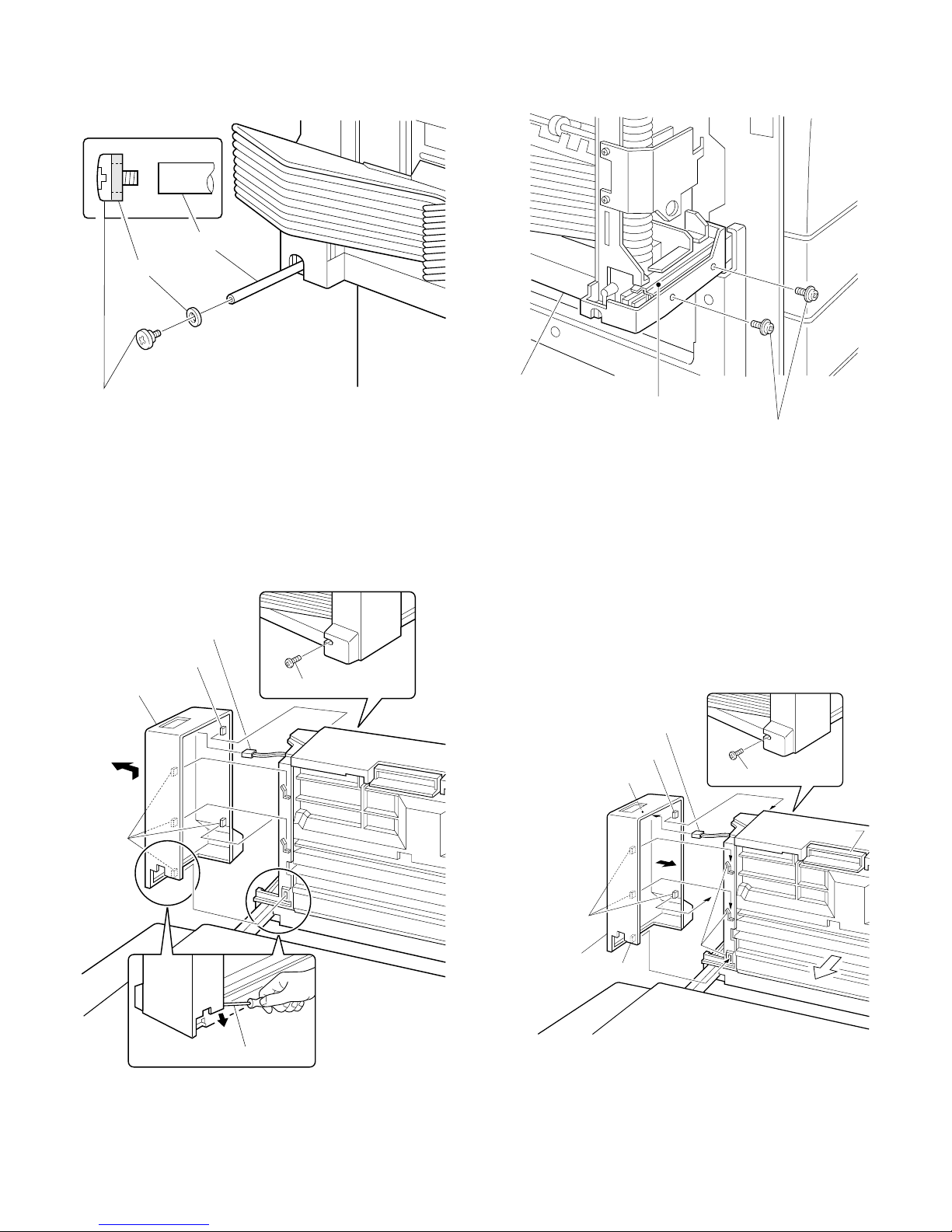
8. Mount the stopper.
Mount the felt washer to the stopper screw and secure the screw to
the sorter seat shaft.
Shaft
Felt washer
Stopper screw
9. Remove the sorter’s front cabinet panel.
Remove the front cabinet panel screw.
Next, using a screwdriver, pry open the lower part of the front cabinet
panel to pull the lowest tab from the slot in which it is anchored.
Pull the front cabinet panel slightly up and out to remove it.
Disconnect the connector which is plugged into the front cabinet
panel.
Connector
Tab
Front cabinet panel
Front cabinet panel screw
10. Attach the sorter to the sorter seat.
Install the M4 x 8 sorter securing screws (2 pcs.) in the screw holes
on the sorter to attach the sorter to the sorter seat.
Sorter
Slide rail
Sorter securing screws
(M4 x 8)
11. Mount the sorter’s front cabinet panel.
Plug the connector from the sorter into the circuit board inside the
sorter’s front cabinet panel.
Fit the tabs on the left side of the front cabinet panel behind the ribs
on the sorter, and slide the tabs on the right-hand side of the front
cabinet panel behind the ribs in the sorter.
Check to be sure the tabs are securely positioned behind the ribs and
inserted properly into the slot.
Secure the front cabinet panel using the screw which was removed in
step 9.
Tab
Straight-edge screwdriver
Tab
Front cabinet panel
Circuit board
Tab
Connector
Tab
Front cabinet panel screw
Lock lever
Ribs
5 – 26
Page 56

12. Connect the sorter connector.
Remove the sorter connector cover securing screw which is mounted
to the rear cabinet panel of the copier and remove the sorter connector cover.
Connect the sorter connector to the connector on the copier and
secure it using the sorter connector securing screw.
Sorter connector cover
Securing screw
Securing screw
(6) SF-S15 (20-Bin Sorter)
SF-S15
Parts list
Support guide
Sorter se at
Sorter seat mounting
fixture (1 pc.)
Sorter connector
Plug the copier into a grounded outlet and turn the
power switch on.
Then, follow the procedure below.
13. Set the mode.
• Operate the copier keys to set the mode.
C
0/
0/
The above key operation will display the currently set mode.
2
6
1
• When only the SF-S18 is to be set, immediately after the above
key operation, operate the keys as follows:
1
0/
• If the mode is to be set in combination with other options, use the
table shown below to add up the total of the setting values for all
the peripheral devices to be set, and set that total value.
For example, if the SF-S18 and RADF are to be set, the total
setting value is 1 + 10 = 11.
Operate the keys as follows:
Sorter seat mounting
screws A (2 pcs.)
Sorter seat mounting
screws B (1 pc.)
Bracket mounting
screws B (2 pcs.)
Unplug the copier and follow the procedure below.
1. Install the support guide.
Hook the pawls (two locations) of the support guide to the inside of
the copier paper exit end to install the guide as shown in Fig.
Support guide
1
RADF 1 Stand/paper drawer 4 SF-S18 10
ADF 1
1
5 – 27
Page 57

2. Mount the sorter seat to the desk.
Remove the two cut-outs in the cabinet panel on the left side of the
desk.
Secure the two sorter seat mounting screws A to the desk.
Next, hook the sorter seat onto the two sorter seat mounting screws
A which were secured to the desk, and then use the one sorter seat
mounting screw B to secure the sorter seat mounting fixiture as
shown.
4. Place the sorter on the sorter seat.
While holding the handle, place the sorter on the sorter seat’s guide
rails and push it gently as far back as it will go.
When doing this, confirm that the rollers at the front of the sorter are
correctly seated on the sorter seat.
Rear
Guide rail
Guide roller
Guide rail
Guide roller
Front
Sorter seat mounting
Cut-out
Sorter seat mounting
fixture
Sorter seat
screws A
Cut-out
Desk
Sorter seat mounting
screw B
3. Remove the front panel of the sorter.
Loosen the four mounting screws in the front panel of the sorter and
remove the panel.
Mounting
screws
Front panel
of sorter
Sorter
Sorter
Sorter seat
Handle
Sorter seat
5. Remove the rear cabinet panel from the copier
and cut out the notch in the cabinet panel.
Remove the four screws which secure the rear cabinet panel of the
copier to remove the rear cabinet panel.
Cut out the notch (one location) in the cabinet panel.
Mounting
screws
Mounting
screws
Rear cabinet
panel
Mounting screws
Notch
5 – 28
Page 58

6. Connect the sorter connectors.
Use the two bracket mounting screws to secure the bracket attached
to the sorter harness to the frame of the copier.
Connect the 6-pin and 10-pin sorter connectors to the 6-pin and
10-pin connectors of the copier and insert the tie band into the hole
under the board installation part.
Bracket
mounting
screws
Bracket mounting
screws
9. Adjust the clearance between the sorter and the
copier.
Push the sorter gently against the copier’s left cabinet panel. The
clearance spacers attached to the back of the sorter will determine
the standard clearance between the sorter and the copier. Turn the
adjustment knobs on the sorter seat to adjust the clearance so that
the spacers are touching the copier.
After adjusting the clearance, remove the clearance spacers.
Adjustment knobs
Tie band
Bracket
6-pin connector
10-pin connector
7. Reattach the rear cabinet panel.
Use the four mounting screws to reattach the rear cabinet panel
removed in step (4) in its original position.
Mounting
screws
Rear cabinet
panel
Mounting screws
8. Reattach the front panel of the sorter.
Use the four mounting screws to reattach the front panel of the sorter
removed in step (3) in its original position.
Mounting
screws
Sorter seat
Clearance spacers
Standard
clearance
Clearance
spacers
10. Set the mode.
• Operate the keys on the copier to set the mode.
C 0 / 62
INTERRUPT INTERRUPT
0 /
The above key operation will display the currently set mode.
READY
READY
1
• If only the SF-S15 is to be set, immediately after the above key
operation, operate the keys as follows:
READY
1
0 /
• If the mode is to be set for a combination with other options, add
up the total of the setting values for all the peripheral devices to be
set from the table shown below, and set theat total value.
READY
1
1
Front pan el
of sorter
SF-A17/A56 1 SF-D20/21 4 Sorter 10
Mounting
screws
5 – 29
Page 59
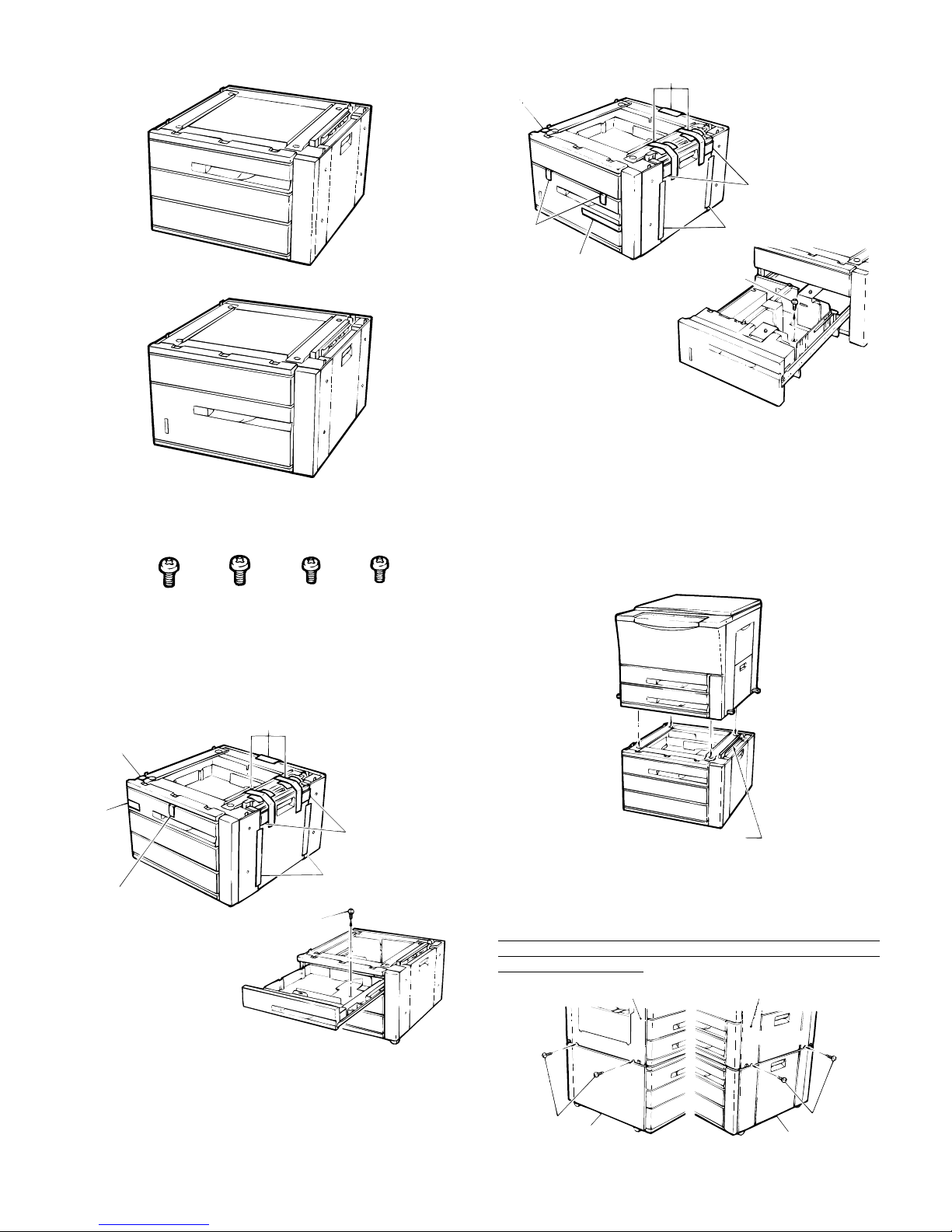
(7) SF-D20/21
D21
Tape
Tape
Shipping
material
SF-D20
SF-D21
Included parts
Mounting screws: 4
Before installation, remove all of the screws, tape,
and shipping material as shown below.
D20
Tape
Tape
Shipping
material
Tape
Tape
Screw
Be sure to unplug the copier before carrying out
the following procedures.
1. Place the copier on the desk.
Place the copier on the desk so that the feet of the copier fit into the
corresponding holes in the desk.
When doing this, be careful that the copier does not come to rest on
the paper guide or other parts of the desk that might be damaged by
the weight of the copier.
Tape
Shipping
material
Screw
Tape
Shipping
material
Paper guide
2. Secure the copier to the desk.
Use the included four mounting screws to secure the copier to the
desk.
In addition to securing the copier to the desk, these screws also
function to electrically ground the desk, so be sure to tighten all four
mounting screws securely.
Copier Copier
5 – 30
Mounting
screws
Left side
Desk
Right side
Desk
Mounting
screws
Page 60

3. Remove the rear cabinet panel from the copier.
Remove the rear cabinet panel by removing the four screws which
secure it to the copier.
Screws
Rear ca bi n et
panel
6. Move the copier to the desired installation
location.
7. Lock the casters.
Move the lock levers of the two casters (one each left and right) at the
front side of the desk downward in the direction indicated by the
arrow in order to lock the casters.
Desk
Screws
4. Connect the desk relay harness.
Remove the screw which secures the cover of the connector access
hole in order to remove the cover.
Next, remove the temporary connector which is attached to the 14-pin
connector of the desk relay harness, and connect the 14-pin connector to the connector on the desk.
* Note that the temporary connector will no longer be used.
Screw
Cover
14-pin connector
5. Remount the rear cabinet panel onto the copier.
Remount the rear cabinet panel which was removed in Step 3 in its
original position and secure it with the four mounting screws.
Caster
Lock lever
Caster
Lock
8. Lower the adjuster to secure the desk in place.
Use pliers or a wrench to loosen the lock nut of the adjuster, and then
turn the adjuster to lower it to the floor in order to secure the desk in
place.
After lowering the adjuster, re-tighten the lock nut all the way up as
far as it will go in order to lock the adjuster.
Lock nut
Adjuster
★ For the SF-D20
(The initial paper size setting is A4R for the AB system and 8 1/2 x
11R for the inch system.)
9. Pull out the paper cassette.
Lift up on the handle on the paper cassette and pull the cassette out
from the desk until it stops, and then lift up on both sides of the back
of the cassette in order to pull it all the way out of the desk.
Screws
Rear cabinet
panel
Screws
5 – 31
Page 61

10. Adjust the positions of the front and rear side
plates.
Remove the mounting screws (two each) which secure the front and
rear side plates, fit the two side plates into the appropriate positions
marked on the cassette corresponding to the desired paper size, and
then secure the side plates once again with the mounting screws (two
each).
Front si de pla te
Rear si d e pl a t e
Screws
Screws
Paper size detection spacer position diagram
AB system
A3
A4
A4R
A5
B4
B5
B5R
EXTRA
Inch system
11. Adjust the position of the rear edge plate.
Remove the rear edge plate and fit it into the cassette at the position
corresponding to the desired paper size.
Rear edge plate
12. Set the paper size detection spacer.
Change the position of the paper size detection spacer to the position
corresponding to the desired paper size.
Paper size delection spacer
8 1/2 x 14
8 1/2 x 11
8 1/2 x 11R
11 x 17
EXTRA
13. Change the paper size indicator.
Remove the paper size indicator and re-insert it so that the paper size
for which the cassette has been set is visible in the paper size indication window.
Note that paper size indications are printed on both sides of the paper
size indicator.
Paper size indicator
(Example: Position for A3 size paper)
5 – 32
Page 62

14. Re-insert the paper cassette.
Lift up on both sides of the back of the paper cassette and, while
aligning the right guide on the cassette with the guide rail as shown in
the figure, push the cassette into the desk along the guide rails.
After doing this, confirm that the cassette moves in and out smoothly.
Guide rail
Guide
15. Place the paper in the cassette.
Place the paper in the paper cassette.
When doing this, do not stack the paper higher than the maximum
height line indicated on the cassette.
Next, push the cassette all the way into the desk as far as it will go.
• If the mode is to be set for a combination of optional equipment,
add together the setting values shown in the table below for each
peripheral device, and set the mode to the total setting value.
For example, to set the mode for a combination of the SF-D20 and
the SF-S53, the total setting value is 4 + 10 = 14, so the key
operation sequence is as follows.
READY
41
SF-A17/A56 1 SF-D20/D21 4 Sorter 10
★ For the SF-D21
(The initial paper size setting is A4 for the AB system and 8 1/2 x 11
for the inch system.)
17. Pull out the large-capacity paper cassette.
Lift up on the handle on the paper cassette and pull the cassette out
from the desk until it stops (the paper loading position), and then lift
up on the casette handle once again and pull the cassette all the way
out of the desk.
Maximum height line
16. Set the mode.
• Operate the keys on the copier to set the mode.
C 0 / 62
The above sequence of key operations will display the current
setting value.
INTERRU PT INTERRUPT
READY
READY
10 /
• If only the SF-D20 is being set, immediately after the above key
operation sequence, perform the following key operation sequence
to set the mode.
READY
18. Adjust the positions of the front and rear paper
guides.
Remove the mounting screws which secure the front and rear paper
guides, fit the two paper guides into the appropriate positions corresponding to the desired paper size, and then also secure the
mounting screws into the holes corresponding to the desired paper
size.
Rear paper guide
Front paper guide
40 /
5 – 33
Page 63

19. Adjust the position of the rear edge paper
guide.
Loosen the two screws which secure the rear edge paper guide until
it becomes possible to move the paper guide.
Next, fit the rear edge paper guide into the appropriate position corresponding to the desired paper size, and then also secure the two
mounting screws into the holes corresponding to the desired paper
size.
Rear edge paper guide
21. Change the paper size indicator.
Remove the paper size indicator and re-insert it so that the paper size
for which the cassette has been set is visible in the paper size indication window.
Note that paper size indications are printed on both sides of the paper
size indicator.
Paper size indicator
20. Set the paper size detection spacer.
Change the position of the paper size detection spacer to the position
corresponding to the desired paper size.
Paper size
detection spacer
(Example: Position for A3 size paper)
Paper size detection spacer position diagrams
AB system
A4
A4R
B4
B5
B5R
EXTRA
22. Re-insert the large-capacity paper cassette.
Lift up on the handle of the large-capacity paper cassette and re-insert in as far as the paper loading position.
23. Place the paper in the cassette.
Place the paper in the paper cassette.
When doing this, do not stack the paper higher than the maximum
height line indicated on the cassette.
Next, push the cassette all the way into the desk as far as it will go.
Maximum height line
Inch system
8 1/2 x 14
8 1/2 x 11
8 1/2 x 11R
EXTRA
5 – 34
Page 64
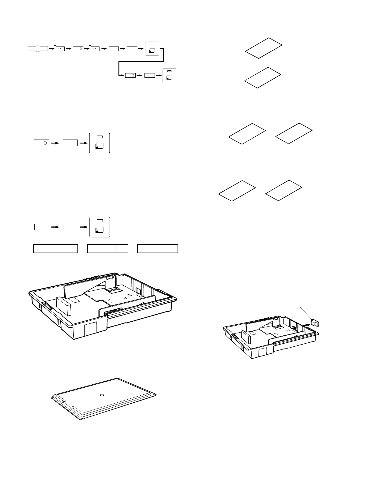
24. Set the mode.
• Operate the keys on the copier to set the mode.
C 0 / 62
INTERRUP T INTERRUPT
The above sequence of key operations will display the current
setting value.
READY
READY
10 /
• If only the SF-D21 is being set, immediately after the above key
operation sequence, perform the following key operation sequence
to set the mode.
READY
40 /
Size label for i ndi cat ion pl at e
AB system
Inch system
8½ x 5
Cassette size label
AB system
A5 1s heet
1sheet
½
• If the mode is to be set for a combination of optional equipment,
add together the setting values shown in the table below for each
peripheral device, and set the mode to the total setting value.
For example, to set the mode for a combination of the SF-D21 and
the SF-S14, the total setting value is 4 + 10 = 14, so the key
operation sequence is as follows.
READY
41
SF-A17/A56 1 SF-D20/21 4 Sorter 10
(8) SF-IC11
A3 · A4 · A4R · A5 · B4
Inch system
8½ x 11 · 8½ x 11R
8½ x 14 · 8½ x 5½
11 x 17
two sheets ea c h
two sheets ea c h
* Be sure to store any parts with care that are not used because
they are necessary for changing the papersize.
Before performing the following procedure, be sure to
remove the power plug of the copier main unit.
1. To remove the stopper for the packaging
cassette unit.
Remove the stopper for the packaging the paper pressure plate in the
cassette unit.
Stopper f or pac kaging
SF-IC11
Cassette main unit
Parts i ncl uded
Cassette cover:1pc.
When using default setting:
★ Skip to step 7 and perform the following steps.
Initial set paper size is A3 or 11 x 17.
5 – 35
Page 65

When using after changing paper size:
2. To change the size setting of side plate F and
side plate R.
Insert side plate F and side plate R into the cassette main unit and
align them on the marking for the desiredsize, and secure the side
plates with fixing screws (2 pcs. each).
Side plate R
Fixing screw
Fixing screw
Side pl at e F
3. To change the size position of the rear end plate.
Remove the rear end plate from its rear storage place, and insert this
into the cassette main unit for the desired size.
When you switch the size to A5 or 81⁄2 x 51⁄2, fix this plate to the
rotary plate by using the screw that is attached to the rear end
plate.
Rear end plate
4. To set the size detection spacer.
Reposition the size detection spacer for the desired paper size.
Size detec t i on sp acer
Setting diagr am f or s i ze detec ti on spacer
(AB system)
A3
A4
A4R
A5
B4
B5
B5R
EXTRA
(Inch system)
8 1/2 x 14
8 1/2 x 11
8 1/2 x 11R
8 1/2 x 5 1/2
11 x 17
EXTRA
5 – 36
Page 66
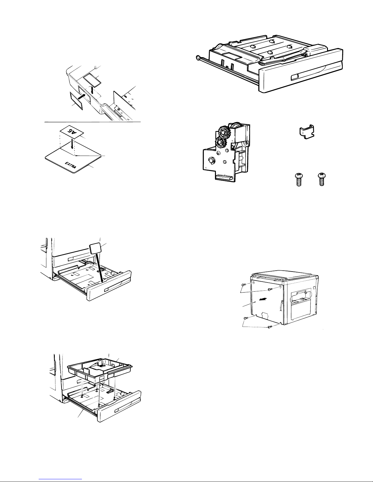
5. To stick the cassette size labels.
Stick the cassette size labels that indicate and correspond to the
desired size on the marked positions for sticking (2 positions). If you
change the size to A5 or 8-1/2 x 5-1/2, take out the paper size
indication plateand stick the size label on the indication plate and
align the sticking line as shown in the figure.
Size label
(9) SF-DM11
Size label
Size lab el f or i ndi cat i on pl at e
Label stic ki ng l i ne (w hi te)
Paper size i nd i cat ion pl ate
6. To change the paper size indication plate.
Take out the paper size indication plate and insert it so that the name
of set paper size can be seen through the paper size indication
window.
The paper size is written on both front and rear faces of the paper
size indication plate.
Paper size i nd i cat ion pl ate
Parts included
Right s topper:1p c .
ADU dr i v e uni t :1 pc.
Fixing screw(M4 x 8):2pcs.
Before performing the following procedure, be sure
to remove the power plug of the copier main unit.
1. To remove the rear cabinet of the copier main
unit.
Remove the four screws that fix the rear cabinet of the copier main
unit and remove the rear cabinet.
7. To install the cassette main unit on the paper
tray.
Install the cassette main unit by putting the four projections into the
corresponding holes of the paper tray.
Cassette main unit
Paper tray
Fixing screw
Rear cabinet
Fixing screw
5 – 37
Page 67
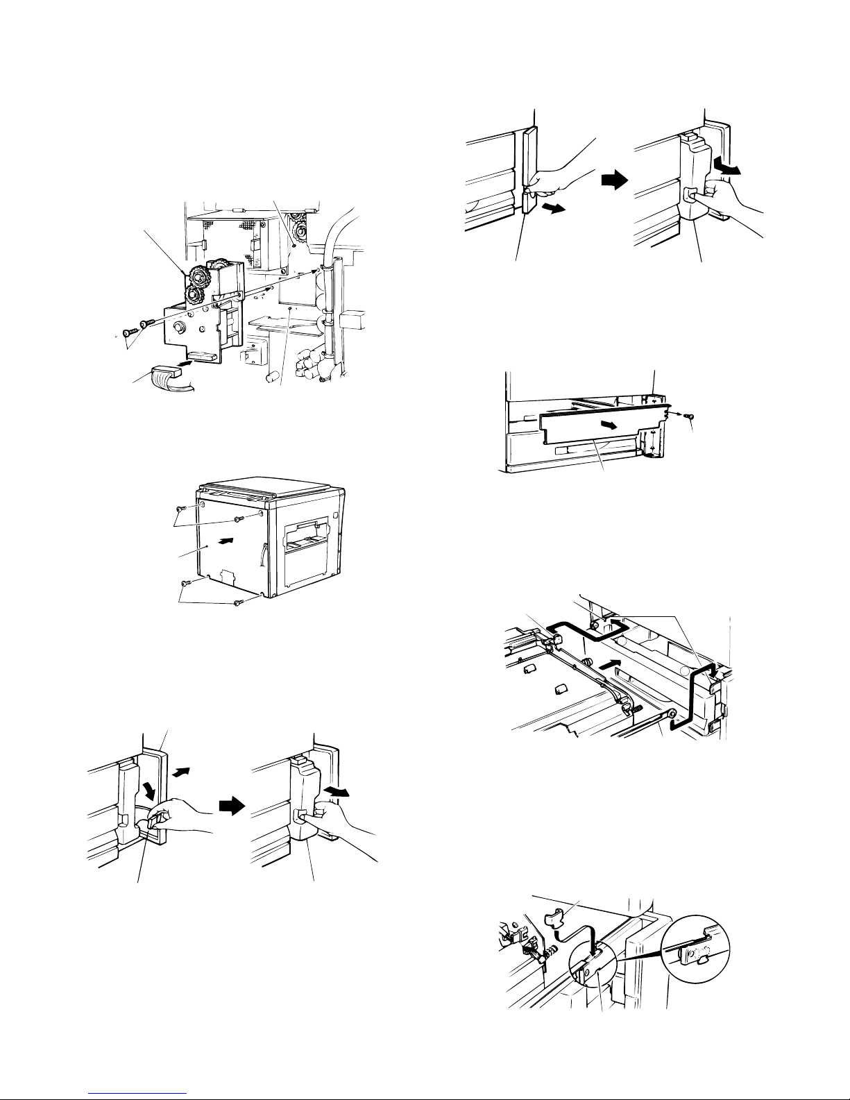
2. To install the ADU drive unit.
Remove the connector, that has been inserted temporarily to the
connector near the copier main unit for connecting with ADU drive
unit.
* The removed temporary connector, it will not be used.
Install the ADU drive unit to the two positioning bosses on the rear
frame of the copier main unit, and secure this with two fixing screws.
Then, connect the connector near the copier main unit, to that of the
ADU drive unit.
Positioning boss
ADU drive unit
• When a container fixing lever is not installed
Open the storage cover for the toner collecting container, then
remove the toner collecting container by pulling out and pressing
down on it at the same time.
Fixing screw
Connector
Positioning boss
3. To install the rear cabinet of the copier main unit.
Reinstall the rear cabinet that has been removed in step 1 with four
fixing screws.
Fixing screw
Rear cabinet
Fixing screw
4. To remove the toner collecting container.
• When a container fixing lever is installed
Open the storage cover for the toner collecting container, pull the
container fixing lever to your side and remove the container.
Storage cover
Toner collecting
container
5. To remove the cover plate.
Remove the screw that fixes the cover plate and remove the cover
plate.
Fixing screw
Cover pl at e
6. To install the ADU unit.
Install the ADU unit by inserting the guides to the guide rails.
At this time, the wheel for the left guide of the ADU unit should be
behind the stopper on the left guide rail.
Stoppe r
Guide
1
ADU unit
Guide rall
2
Storage cover
Containe r fixi ng
lever
Toner collecting
container
Guide
7. To install the right stopper.
Insert the right stopper into the notch before the wheel for the right
guide of the ADU unit as shown in the figure.
At the time, ensure that the right side of the ADU unit is locked.
Then push the ADU unit to the innermost recess of the copier main
unit.
Right st pper
Notch
5 – 38
Page 68

8. To install the toner collecting container.
• When a container fixing lever is installed
Reinstall the toner collecting container that has been removed in step
4, restore the container fixing lever, and close the storage cover for
the toner collecting container.
Storage cover
When the matching guide is aligned properly,
perform step 10 in the Installation Procedure.
When the matching guide is not aligned properly,
perform the following Procedure to adjust the
matching guide.
A. Set the mode using the following key operation on the copier main
unit:
C 0 / 2
INTERRUPT
0 /
1
READY
INTERRUPT
5
READY
Toner collecting
container
Container fi xing
lever
• When a container fixing lever is not installed
Reinstall the toner collecting container that has been removed in step
4. Press it down to its original position and push it into the machine as
far as it will go. Close the storage cover.
Toner collecting
Storage cover
container
9. To check and adjust the matching guide.
1 Mark a duplex copy.
2 Remove the duplex unit from the copier main unit, and open the
paper guide.
3 Set the copy that has been made in step I or a sheet of the same
size on the duplex tray. Align the paper to either alignment guide
F, or R, to check the gap. Check to see if the gap between either
of the alignment guides and the paper is from 0 to 0.5 mm.
Paper guide
Then current set value is displayed.
B. To set the adjustment mode, input the set value as shown below
after the operation above:
READY
Set vaiue
CA
(Example) To set a value (5) with one digit, perform the following
operation:
READY
0 / CA
5
(Example) To set a value (15) with two digit, perform the following
opeartion:
READY
1
5
CA
Changing the set value by (1) causes the matching guide width to
move 0.5mm to 0.6mm.
* Criterion for changing set value
1
Factory setting value
99
(Guide width becomes larger.) (Guide width becomes smaller.)
C. Perform the steps 1 to 3 again to check the width.
10. To adjust the center dislocation.
When copy result shows center dislocation as shown in Fig. 1 and
Fig. 2, loosen the four screws (indicated by ↓) that fix the front
cabinet.
Matching guide R
Matching guide F
0 to 0.5mm
b
Directi o n A
a
b
a
Direct i on B
Caution:
When you fix the front cabinet, the gap between a fixing screw and
the cabinet is symmetrical for the fixing screw sections a b.
(Referenc e dr aw i ng)
b
a
5 – 39
Page 69

* In case of Fig. 1
Move the front cabinet to the direction A, tighten the fixing screws
a (2 pcs.) and b (2 pcs.) in this order, and make a copy again to
check that there is no center dislocation.
Fig.1
Image center (i mage of fi rs t copy )
* In case of Fig. 2
Move the front cabinet to the direction B, tighten the fixing screws
a (2 pcs.) and b (2 pcs.) in this order, and make a copy again to
check that there is no center dislocation.
Fig.2
Paper center l i ne
Paper center l i ne
Be sure to unplug the copier and install the unit as
follows:
★ Procedures for installation on the copier
1. Remove the rear cabinet panel from the copier.
Remove the rear cabinet panel by removing the four screws which
secure it to the copier.
Mounting screws
Rear cabinet panel
(10) SF-CM11
Paper Cassette
Included p art s
Paper feed uni t : 1
Image center (i mage of fi rs t copy )
Lift-up unit : 1
Mounting screws
2. Install the lift-up unit.
Connect the connector (black colored) from the copier to the connector of the lift-up unit.
Next, hook the prongs on the lift-up unit into the rear frame of the
copier, fit the lift-up unit into the positioning bosses (two locations),
and secure it with the mounting screws A (2) and B (1).
Insert the twist band on the copier’s harness into the lift-up unit.
Mounting screw B
Mounting screw A
Twist band
Connector
Prong
Lift-up unit
3. Remount the rear cabinet panel onto the desk.
Remount the rear cabinet panel which was removed in step 1 back in
its original position and secure it with the four mounting screws.
Right stopper: 1
Mounting screw s A
(M4 x 30): 2
Mounting screw s B
(M4 x 10): 2
Mounting screws
Rear cabinet panel
Mounting screws
5 – 40
Page 70
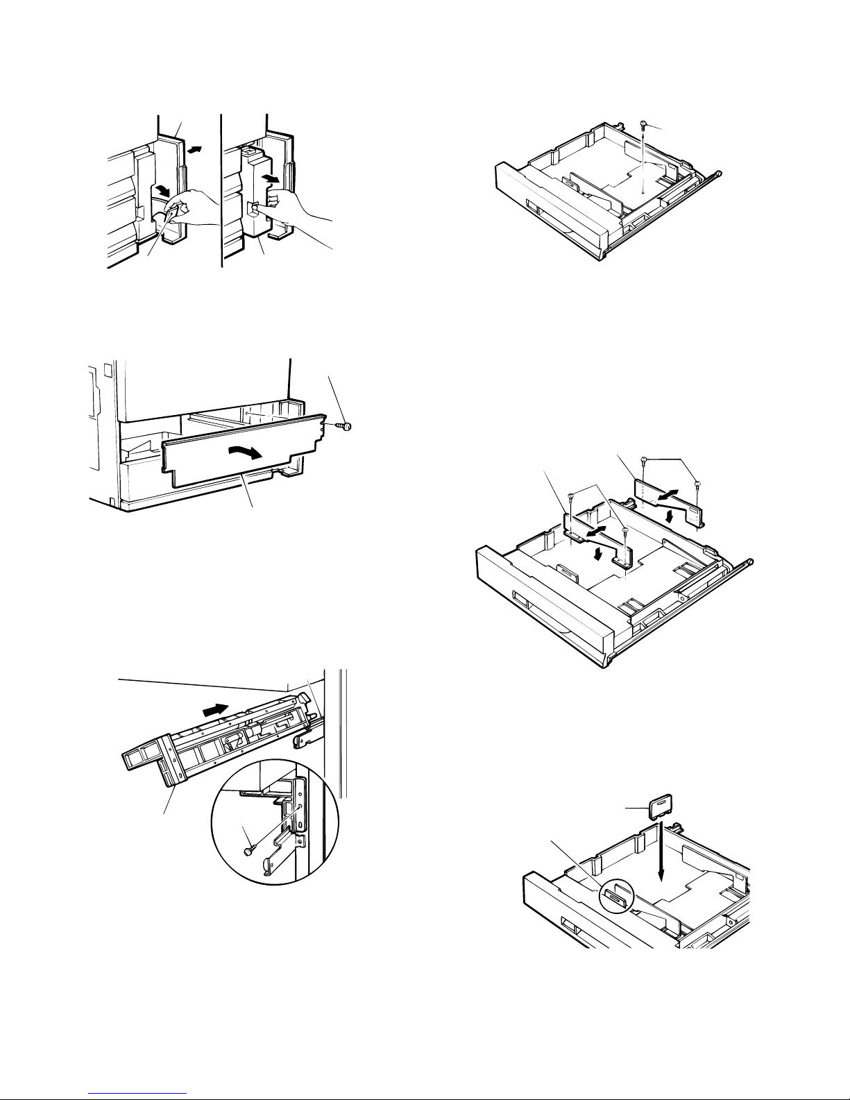
4. Remove the toner collecting container.
Open the toner collecting container cover, pull the fixed lever forward,
and remove the container.
Cover
7. Remove the packing screw from the paper
cassette.
Remove the packing screw which secures the paper pressure plate
inside the paper cassette.
Packing screw
Fixed lever
Toner collecting container
5. Remove the cover plate.
Remove the cover plate by removing the screw which secures it.
Mounting screws
Cover plate
6. Install the paper feed unit.
Fit the groove in the paper feed unit into the guide rail, and then,
while tilting the paper feed unit at an angle of approximately 30°, slide
it all the way back as far as it will go.
Fit the paper feed unit into the positioning bosses (two locations) on
the desk frame, and secure it with one mounting screw B.
The paper size is set to A4 for AB system and 81⁄2" x 14" for inch
system at the factory.
8. Change the positions of the front and rear side
plates.
Remove the mounting screws (2 each) which secure the front and
rear side plates, fit the front and rear side plates into the appropriate
locations marked on the cassette to set the desired paper size, and
then secure the side plates once again with the mounting screws (2
each).
Front si de pl ate
Rear si de pl at e
Mounting
screws
Mounting screws
Guide reil
Mounting
Paper feed unit
screw B
9. Position the rear edge plate.
Remove the rear edge plate from its storage slot and fit it into the
cassette to set the desired paper size.
The rear edge plate is not needed to set the paper size to 11" x 17"
(double letter size).
Rear edge pl at e
Rear edge pl at e s tor age s lot
5 – 41
Page 71

10. Set the paper size detection spacer.
Change the position of the paper size detection spacer to match the
desired paper size.
Paper size detection spacer
12. Fit the paper cassette guides into the guide
rails.
Insert the paper cassette by fitting the guides of the paper cassette
into the guide rails.
When doing this, insert the paper cassette all the way in so that the
cassette’s left guide roller goes past the stopper on the guide rail.
Example:A3setting
Paper size det ect i on spac er posi t i on di agr am
AB system
A3
A4
A4R
A5
B4
B5
B5R
EXTRA
Inch system
Stoppe r
Guide rails
1
Guide
2
13. Mount the right stopper.
Fit the right stopper into the notch in front of the paper cassette’s right
guide roller as shown in the figure.
When doing this, confirm that the right side of the paper cassette is
locked.
Pight stopper
Notch
8 1/2 x 14
8 1/2 x 11
8 1/2 x 11R
11 x 17
EXTRA
11. Change the paper size indicator.
Remove the paper size indicator and reinsert it to show the paper
size for which the cassette has been set in the paper size indicator
window.
Note that paper sizes are printed on both sides of the paper size
indicator.
Paper size i ndicator
14. Install the paper cassette.
Lift the rear sides of the paper cassette and insert the both sides of
guides into the Copier by fitting them to the guide rails as shown in
the figure. Make sure that the paper cassette slides smoothly.
Guide rail
Guide Guide
Guide rail
5 – 42
Page 72

15. Place the paper.
Place the paper in the cassette.
Do not stack the paper higher than the maximum height line.
Next, push the cassette all the way into the copier.
• If misaligned as shown in Fig. 1
Move the front cabinet panel in direction A and retighten the two
mounting screws a and then the other two screws b. Make
another copy to confirm that the center is no longer misaligned.
Maximum
height l in e
16. Install the toner collecting container.
Reinsert the toner collecting container which was removed in step 4
into its original position, return the fixed lever to its original position,
and then close the cover.
Cover
Fig.1
Center li ne of the fi rs t c opy i mage
Paper center line
• If misaligned as shown in Fig. 2
Move the front cabinet panel in direction B and retighten the two
mounting screws a and then the other two screws b. Make
another copy to confirm that the center is no longer misaligned.
Fig.2
Center li ne of the fi rs t c opy i mage
Paper center line
Toner collecting
Fixed lever
container
17. Adjust any center misalignment.
Make a copy, and if there is any center misalignment such as that
shown in Fig. 1 or Fig. 2, loosen the four screws (indicated by the
arrows) which secure the front cabinet panel.
b
NOTE:
The mounting screws a and b will be in the symmetrical positions
when they are tightened, as shown right.
(Refer enc e fi gu re)
a
Direction A
Direct i on B
b
a
b
a
5 – 43
Page 73
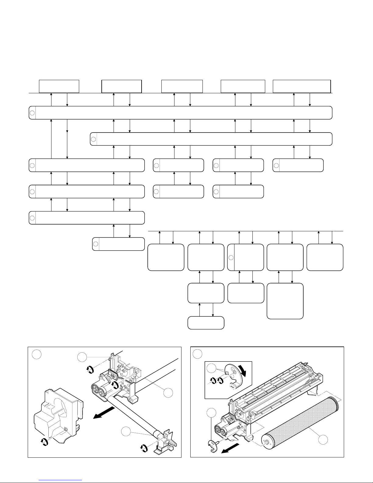
[6] DISASSEMBLY AND
REASSEMBLY
1. Process unit
Drum
1
Loosen two blue screws that hold the drum
2
positioning plate F assy.
Rotate the drum positioning plate F assy clockwise
3
to remove.
4
Remove the drum assy.
Toner receiver
Remove the process cover (1 screw) and remove the process unit from the copier (3 screws).
5
Remove the toner
11
receiver. (4 screws)
BL PWB UN
Detach the clam shell mechanism (4 screws).
Unfasten the blank
6
lamp connector.
Remove the blank
7
lamp PWB.
DR mark sensor
PWB
Remove the
DR mark sensor
PWB from the
BL PWB unit
(1 screw).
8
9
Separation solenoid
Unfasten the
harness
connect or from
the separation
solenoid.
Discharge
lamp unit
Unfasten the discharge
lamp harness connector.
Remove the discharge
lamp unit (1 screw).
Separator pawl
Remove the
12
separation
solenoid.
Cleaning blad e
Remove the cleaning
10
blade (3 blue screws).
DR sensor
Remove the
DR sensor
moun ting plat e
unit (1 screw).
Process volume
PWB
Remove the
process volume
PWB (2 sc r ews).
Remove the
separation pawl
unit from the
process unit.
Remove the
separation
pawl unit (R).
Remove the DR
sensor cover
mounting screws
(2 pcs.) and
separate the DR
sensor from the
mounting plate .
Counter roller
A
1
B
3
1
2
1
4
6 – 1
Page 74

C
5
5
F
10
D
G
11
7
E
6
H
12
9
8
6 – 2
Page 75

2. Manual feed multicopy unit
Counter roller
1
2
Remove the reverse
roller holder (2 screws).
3
Remove the counterroller
unit (1 plastic E-ring).
Takeup roll er
Remove the right side panel of the copier (3 screws).
Remove the manual feed multicopy unit (4 screws, 2 connectors).
Remove the partition
12
plate from the cam lever.
Remove the takeup
13
roller.
Paper feed
roller
4
Remove the manual feed multicopy solenoid (2 screws).
5 6
Remove the connection gearwheel (1 E-ring).
7
Remove the manual feed drive gearwheel (1 C-ring).
8
Remove the spring clutch, small (2 E-rings, 1 pin).
Spring clutch, sm all Spring cl u tch, l arge
Remove the spring
clutch, large (1 E-ring).
9
Remove the spring (1 spring).
Remove the front side bushing
10
of the drive roller shaft assy
(1 E-ring, 1 clutch spring bushing).
Remove the dr i ve roller sha ft
11
assy.
Remove the paper feed roller from
14
the drive roller shaft assy (3 E-rings,
1 connection gearwheel, 1 pin).
A
A'
2
1
2
1
6 – 3
Page 76

B
E
13
3
3
C
F
6
4
5
8
7
14
D
10
9
11
6 – 4
Page 77

3. Paper feed unit
Paper feed
roller
1
Unfasten the harness of the spring clutch.
2 9 13
Remove the manually set E-ring.
Move the clutch shaft to the location where the pickup roller lever
3 10 14
disengages from the frame.
4 11
Remove the manually set E-ring.
5
Remove the pickup roller lever.
6
Remove the paper feed roller.
NOTE:
The one-way clutch is on
the rear frame side
7
NOTE:
Takeup roller Counter roller Solenoid
8 12
Remove the tension spring.
Remove the manually set
E-ring.
Move the shaft, including the
gearwheel.
Remove the counter roller.
Remove the takeup roller.
The side with a protrusion is
on the rear side.
(clutch side).
Remove the spring.
Remove the solenoid lever.
Remove the solenoid
(on the line).
6 – 5
Page 78

A
2
D
1
9
8
11
3
B
4
E
12
5
10
13
14
C
7
6
6 – 6
Page 79

4. Transport baseplate unit
Suction unit transfer belt
1
Pull the paper entry side rolle towards
2
the paper exit side, then remove it.
Move the suction transfer belt
3
to the front side, then remove it.
Note the arrowhead that shown
NOTE:
on the suction unit transfer belt.
NOTE:
H specificafions mode remove
the demo isture heater lamp in
the suction section.
(Remove heater connector
b
in Fig. B .)
Paper stop
roller
Remove the transport baseplate from the machine
(4 screw on front, 2 on rear, 2 connectors).
Remov e the D V guide
4
(6 screws).
Remove the spring and the
5
auxili ar y ro ller.
Remove the paper stop clutch
6
(1 screw, and loosen 1 setscrew).
Remove the front side gearwheel (one
7
each of E-ring, pin, washer, spring).
Remove the bearing
8
(one each on front and rear).
Paper stop
clutch
10 Remove the connecting plate
5
in Fig. F . (2 screws)
11
Remove the stopper and the
22T gear.
12 Remove the P.S clutch
Screw
Connector facing down ward
Set screw
Suction lift lever
Loosen screw
a in Fig. A and
shif t the suc tion lift lever to R side ,
and the heater unit can be removed.
When removing the transport plate unit,
remove the DV tank, the front cabinet,
the process unit, and the upper cassette
(ADU unit) in advance.
Before removing the upper cassette, it is
advisable to remove the paper feed unit
in advance.
Since the fuser unit will serve as the guide
rail for removing and assembling the
transport base plate, do not remove it.
Open the right cabinet.
9
Remove the paper stop roller.
When installing the transport base plate unit
Fit the arrow mark in the DV guide with
1
the gr oov e in t he lef t s ide of the r ai l
transport base plate in the multi paper
feed section of the main body and the
mark in the fusing unit cover.
Coupling
Transport roller
Securely engage the transport roller coupling
2
with the main body coupling. If not, the unit
cannot be inserted fully.
Check that the roller can be turned manually.
(If the couplings are not securely engaged,
the roller cannot be turned manually.)
6 – 7
Page 80

A
a
D
4
4
1
1
B
1
E
5
9
8
5
5
6
8
7
1
1
C
3
b
2
F
5
3
12
11
6 – 8
Page 81
5. Fuser unit
Heater lamp
1
2
Unfasten the heater lamp connectors on both sides.
3
Unfasten the thermistor and thermostat connectors.
4
Remove the lamp holder unit (2 screws).
5
Remove the heater lamp.
6
Remove the tension spring and release the fuser tension.
Upper/lower
heat roller
Remove the fuser cover (2 screws).
Upper/ l o wer
separation pawls
Cleaning roller
Remove the cleaning roller springs on the
14
front and the rear sides.
15
Remove the upper cleaning roller
When the clam shell is
NOTE:
assembled, the periphery
7
of th e mecha n ism mus t
meet together.
Ensure gear mesh
is correct. Ensure
clamshell is seated
8
properly.
9
When installing the
NOTE:
lower heat roller, the
pawls must be
10
positioned away from
the roller before
closing the lower
pawl hol ding plate,
then restore pawl s to
11 13
proper position after
installing roller.
(Discharge brush)
The discharge brush must be vin contact
with the upper heat roller.
Remove the clam shell mechanism holding screws (2 screws).
Open the fuser unit.
Remove the upper heat
rolle r a ssy.
Remove the upper
12
separation pawls.
Open the lower pawl holder bracket assy (2 screws).
Remove the lower heat
roller assy.
Remove the lower
separation pawls.
(Thermistor)
·
The center of the thermistor must be in
contact with the heat roller.
Clean thermistor surface
·
using alcohol.
NOTE:
Do not use the spare screw hole.
Upper heat roller
Lower
cleaning roller
Put the front/rear/under CL
16
spring in the frame groove
and release the pressure.
Thermistor
Thermistor
6 – 9
Page 82

A
4
1
3
3
2
5
E
14
B
7
6
F
15
7
C
6
G
12
8
16
D
9
16
13
11
10
6 – 10
Page 83

6. Duplex copy unit
Counter
roller
Remove the front and rear side two
16
counter roller tension springs.
Front frame Rear frame
Spring color Black White
Spring tension Strong Weak
Install the assembly so the
NOTE:
protrusion on the clutch spring
faces down. The protrusion
should never face the transport
path.
Paper feed
roller
Remove the double side copy tray.
1
Remove the front cover (2 screws).
2
Unfasten two connectors.
3
Remove the pivot holding plate screw (one each on both sides).
4
Remove the upper and transport paper guides from ADU.
Remove the clutch stopper plate
12 5
(1 screw).
13
Remove the clutch side E-ring.
Move the bushing and take out the paper
14
feed roller drive shaft onto the front frame side.
Remove the clutch retaining plate
(1 screw).
Loosen the s et scr ew an d remove the
6
clutch.
Remove the takeup roller drive shaft
7
(2 on front, 1 on rear).
Takeup rol ler
17
Remove the counter roller.
15
Remove the paper feed roller.
Push down the spring holder and remove
8
the takeu p rol le r uni t fro m ADU.
Remove the takeup roller arm side E-ring
9
(rear side).
Remov e the paper holder ar m s i d e E - r ing
10
(front and rear).
11
Remove the takeup roller.
12
Remove the spring (2pcs.)
13
Remove the reversing roller.
6 – 11
Page 84

A
a
D
10
9
11
10
8
1
B
4
E
2
13
3
12
12
C
5
7
7
6
6 – 12
Page 85

7. Rear frame side major components
Paper feed
drive unit
1
Remove the rear panel (4 screws).
2
Remove the main PWB connectors (13 connectors).
3
Remove the main PWB unit from the copier (1 screw).
Remove the paper feed
4
drive unit (4 screws).
Remove the variable paper feed
7
speed un it (4 screws).
8
Remove the variable speed clutch unit.
Variable paper
speed un it
5
Remove the joint plate (2 screws).
6
Remove the main drive side pulley holding E-ring, then remove the drive belt.
Main drive uni t (bel t)
Unfasten the high voltage unit connectors (6 connectors), and
9
remove the ground harness from the copier chassis (1 screw each).
10
Remove the high voltage PWB from the suction duct unit.
11
Remove the suction unit (6 screws).
A
1
1
B
2
3
6 – 13
Page 86

C
F
9
9
9
4
10
9
D
5
6
G
11
E
8
7
6 – 14
Page 87

AC pow er
supply PWB
DC pow er
supply PWB
Pape r exit gate
solenoid
1
2
3
A
Remove the rear panel of the copier (4 screws).
Remove the rear side screw of the left side panel (1 screw).
Remove the AC power supply board (5 screws, 6 connectors).
4
DC power PWB identification
100V system
White label
Remove the DC power supply PWB (5 screws, 1 connector).
200V system
Red label
5
C
Remove the paper exit gate solenoid
(2 screws, 2 connectors).
4
1
1
2
B
D
3
5
6 – 15
Page 88

8. Operation panel unit and document
size sensor board (light receive side)
Operation
panel
1
Open the front panel.
2
Remove the middle panel (5 screws).
Remove the glass holding plate and front frame side right
3
and left side screws (5 screws).
Remove the s cr ews that hold the magne ti c cat ch plate
4
(one each on two l oc at i ons).
5
Remove the operation panel unit.
Remove the operation
6
panel from the operation panel
unit (15 screws, 6 connectors).
Document siz e se n so r
board light receive side
Remove the document
7
size sensor board ( screw).
LCD unit
Remove the LCD control PWB from the operation panel
8
unit. (2 screws, 4 connectors)
Remove the LCD control PWB mounting angle from the
9
operation panel unit. (2 screws)
Remove the operation PWB from the operation panel unit.
10
(9 screws)
11
Remove the LCD unit. (4 screws, connector)
A
C
1
2
B
3
7
4
5
6 – 16
Page 89
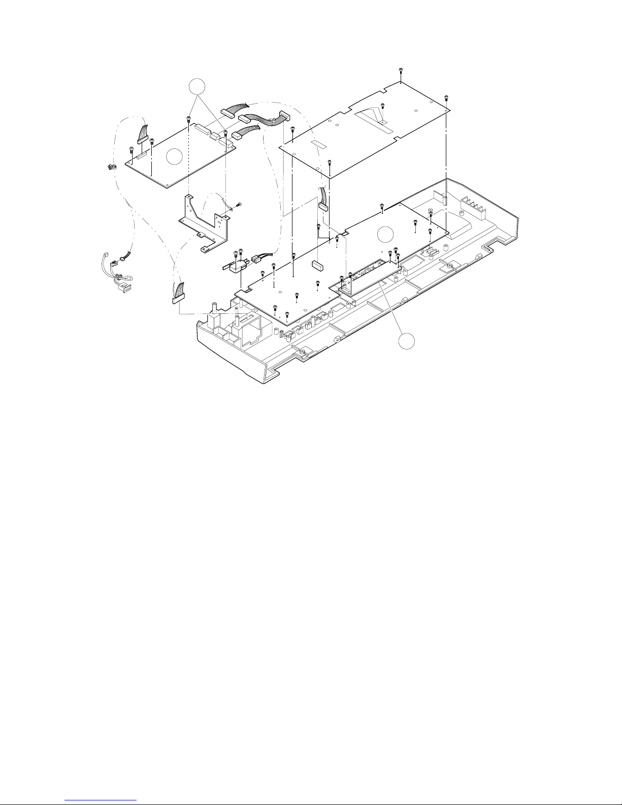
9
8
10
11
6 – 17
Page 90

9. Optical unit
Copy lamp Copy l a mp unit #2/3 mirror base unit #4/5 mirror base unit
1
Remove the original guides (L, R) and remove the table glass (two each screws).
Move the copy lamp unit to the cut in the
rear of the top cabinet and remove the
2
rear frame side copy lamp electrode
holding screw.
3
Remove the copy lamp.
NOTE: Note the direction of the copy lamp.
FR
It must be installed with the bulge of the copy
lamp near the rear side, as s ho wn in the figur e.
Remove the operation panel.
4
Remove the top ca bi n et , lef t.
Remove the left cabinet.
5
Remove the wire
holding plates found on
both frame sides of the
6 11
copy lamp unit, then
Remove the upper dark box cover (2 screw).
Remove the mirror
8
base wire from the
#2/3 mirror base unit.
remove wires from the
side plate s (F, R).
Move the #2/3 mirror
base unit to the square
hole (a) on the front
9
side of the optical
baseplate, then rotate
Rotate the copy lamp
7
unit to remove.
it to remove.
Remove the opt ic a l ha rne ss connectors .
Remove the lens motor connectors.
Remove the lens home position sensor connector.
13
Unfasten the document sensor light receive board
connector. Remove the front cabinet switch junction
harness.
Remove the re ar pa ne l
10
(6 screw).
Record value for
assembly.
Remove the #4/5 mirror
12
motor holdi n g br ac k et
(6 screw).
Remove the mirror base
unit together with the
14
#4/5 mirror motor
holdin g brac k et assy.
A
4
4
1
B
2
10
3
6 – 18
Page 91
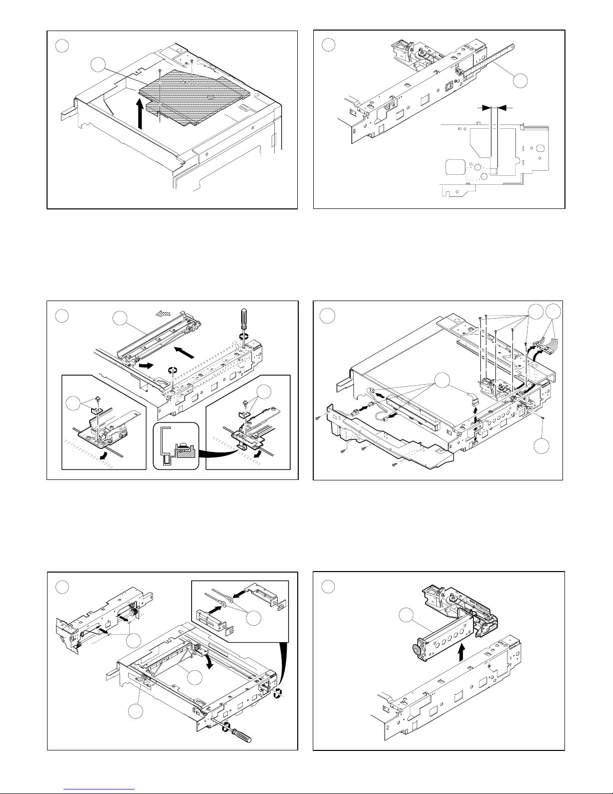
C
5
F
11
P
13
D
7
G
12
F
6
R
6
13
12
E
8
H
14
8
9
a
6 – 19
Page 92

Mirror base wire stretching
(Preliminary checks)
Check the stop position of the wire winding pulley.
Visually check that the wire grooves of the front/rear wire winding
pulleys are at the same level.
If there is a substantial discrepancy between the two, loosen the two
setscrews which are fixing the pulleys and adjust the pulley positions.
After adjustment, tighten the setscrews.
1 Hang the mirror base wire fixing fixture on the tension adjustment
plate hook.
2 Fit mirror base B onto the mirror base positioning plates
(front/rear). Pass the mirror base wire along the outer groove of
the mirror base B pulley.
3 Pass the mirror base wire along the pulley groove in the paper
feed side.
4 Pass the mirror base wire under mirror base B and wind it around
the winding pulley.
At that time, fix the wire groove section in the winding pulley to the
upper position, wind the mirror base wire 9 times, and put the 8th
winding in the groove.
(Rear frame side)
(Rear)
(Fron t)
The first winding position should be 9 - 10mm toward the body
frame from the pulley groove section.
5 Pass the mirror base wire along the pulley groove in the paper exit
side.
6 Pass the mirror base wire along the internal groove of the mirror
base B pulley.
7 Pass the mirror base wire through the wire guide.
8 Attach the mirror base wire tension spring to the long hole in the
optical base plate.
When viewed from the rear frame
(Front frame side)
5
8
7
4
4
2
4
2
6
6
1
5
8
2
3
1
3
6
2
4
6
4
7
When viewed from the front frame
4
6 – 20
Page 93

Mirror base wire tension adjustment
1 Manually turn the mirror base drive pulley to shift mirror base B
which is at the mirror base positioning plate 20 to 30mm to the
paper exit side.
2 Turn the mirror base wire tension adjustment screw clockwise to
apply tension to the wire until the wire tension spring edge makes
contact with the projection of mirror base B.
F
R
Wire tension spring
Mirror base B projection
Apply tension until the spring comes in
contact with the projection.
Tension adjustment plate
Mirror base wire
Tension adjustment screw
3 Manually turn the mirror base pulley to make mirror base B per-
form full scan a few times, and check that the mirror base wire
spring edge is in contact with the projection of mirror base B. If
they are not in contact with each other, adjust by turning the
tension adjustment screw again. In this case, check also that
there is no slack in the wire on the mirror base pulley.
4 Turn the mirror base wire tension adjustment screw 6 turns
counterclockwise. (Then the distance between the mirror base
wire spring and the projection of mirror base B will be about
4mm.)
No. 2/3 mirror base unit installing position
This adjustment is to adjust parallelism of the mirror base B to the
drum surface and the original surface.
1 Manually turn the mirror base drive pulley to bring mirror base B
into contact with the mirror base positioning plate. In this case,
when the front frame side and the rear frame side of mirror base B
are simultaneously brought into contact with the mirror base
positioning plate, the parallelism of mirror base B is proper and
there is no need for adjustment.
Mirror base
wire
Mirror base B projection
(Perform the same procedures for the front frame side and the rear
frame side.)
Copy lamp unit installing position
1 Pass the front/rear mirror base drive wire between the copy lamp
unit frame and the wire fixing plate.
In this case, do not tighten the wire fixing screw.
2 Press the copy lamp unit onto the positioning plate and tighten the
wire fixing plate.
4.0mm
A
6 – 21
Page 94
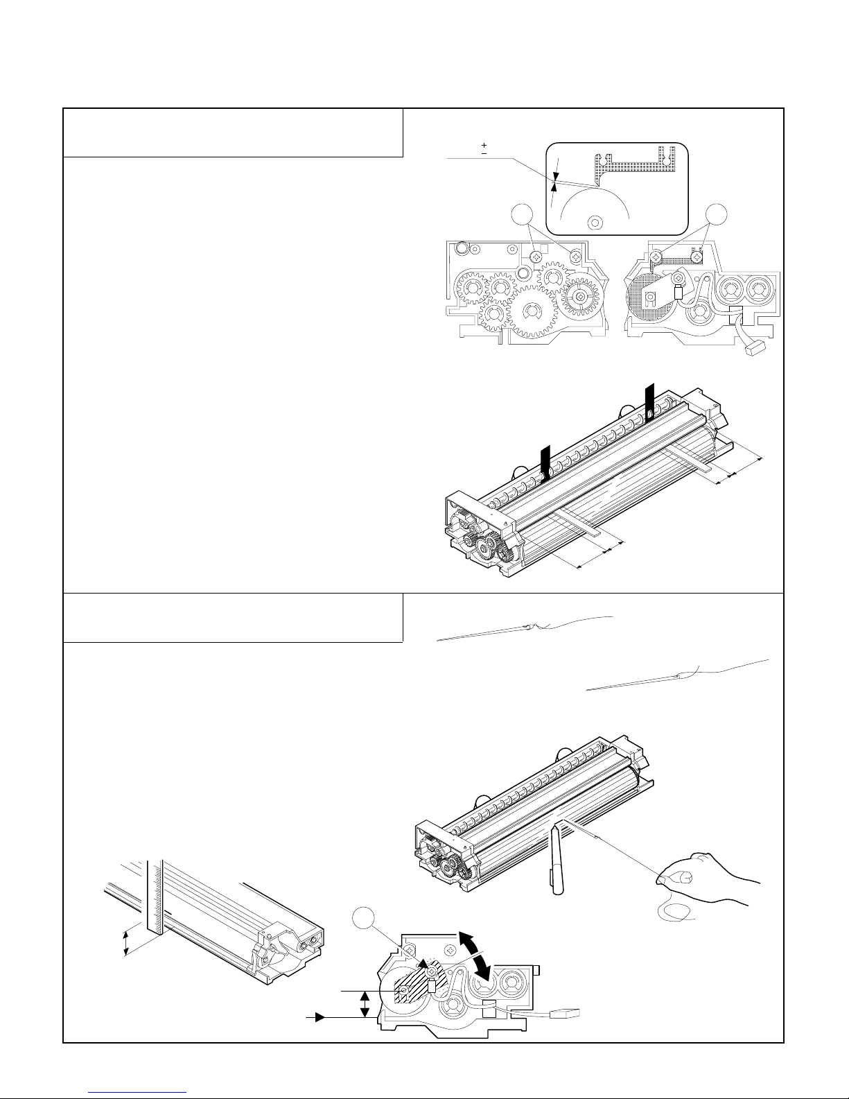
[7] ADJUSTMENTS
1. Developing Unit
(1) Clearance Adjustment of Developing Doctor
Blade
1 Remove the 5 screws and the 5-pin connector which connect
the developer tank to the toner hopper, and pull out the
developer tank.
2 Loosen 4 setscrews A of the developing doctor blade.
(2 setscrews on the rear frame side and 2 on the front frame
side).
3 Insert the feeler gauges into the clearance between the develop-
ing doctor blade and the magnet roller at the points 50-80 mm
away from both ends.
4 While pressing down the developing doctor blade in the arrow
direction, tighten the 4 setscrews to secure the developing doctor blade.
5 Check that the clearance between the developing doctor blade
and the magnet roller is 0.50±0.03 mm at the points 50-80 mm
away from the doctor blade ends.
Caution: Do not damage the developing doctor blade or the
magnet roller during insertion of the feeler gauge.
Tool: UKOGM0075CSZZ (Feeler gauge)
0.03
0.50
0.03
A A
50mm
30mm
(2) Position Adjustment of Developing Magnet
Roller Main Pole
1 Remove the 5 screws and the 5-pin connector which connect
the developer tank to the toner hopper and remove the toner
hopper. Put developing unit on a flat surface.
2 Thread a needle or pin as shown in the figure on the right.
3 While holding the thread, bring the needle near the magnet
roller. (Do not use a clip because it will not provide an accurate
position of the main pole).
4 Use a pen to put a mark on the point of the magnet roller
surface to which the needle is attracted.
5 Measure the distance from the mark to the reference plane on
which the developer tank is placed.
This distance must be 18.4 mm.
If not so, loosen setscrew A of the main pole adjusting plate and
move the adjusting plate in the arrow direction to obtain the
proper distance.
A
18.4mm
30mm
50mm
18.4mm
7 – 1
Page 95

(3) Developing Bias Adjustment
1 Set the measuring range of the digital multimeter to 300 Vdc or
more.
2 Apply the probes to the developing bias output check pin
(BSCP) and the chassis(GND) of the high voltage unit.
3 Perform Simulation 8-1. (The developing bias voltage is output
for 30 seconds.
4 Adjust VR301 for developing bias control so that the output
voltage is –215±5V.
(4) Notes on installing various rollers of the
developing unit
(1) V-rings must be attached in the correct direction.
(2) No gap must exist at ❈ between the V-ring and the roller.
(3) When attaching φ8-ring PRNGP0013FCZZ, φ8-ring
PRNGP0022FCZZ and φ6-ring PRNGP0015FCZZ to the
developing magnet roller,
1) the direction of the V-ring must be as shown in the upper
figure.
2) no gap must exist at ❈ between the V-ring and the roller.
V-ring Φ6
Rear Front
Roller SV (X1)
V-ring Φ6
V-ring Φ8
Rear Front
Magnet roller
V-ring Φ6
Rear Front
V-ring Φ6
Rear Front
Roller S (X1)
Roller MX
V-ring Φ8
V-ring Φ6
V-ring Φ6
(5) Notes on applying the developing side seals
(front and rear)
(1) The side seal must be applied on a surface which is free of oil,
grease and foreign matter.
(2) The side seal must be securely attached to prevent it from
coming off.
D B
Rear Front
7 – 2
C A
Rear
Front
Page 96

2. Processing Unit
Backward
The blank lamp unit
moves forward
The blank lamp unit
moves backward
Forward
(1) Adjustment of Blank Lamp Position
1 Check that the center deviation is 2.0mm or less. (If the center
deviation is more than 2.0 mm, correct it).
2 Set an A3(11x17)-size blank original on the original table, and
with the original cover opened, make a reduced (x 0.64) copy
using an A3 (11 x 17) paper.
3 Measure the width of solid areas. If the width is more than 1
mm, adjust the blank lamp unit position so that the width of the
solid areas is 1 mm or less.
A
B
IA-BI 1mm
1 notch of the adjusting cam : lamp movement 0.5 mm
Half notch of the adjusting cam : lamp movement 0.25 mm
(2) Adjustment of High-Voltage Output Balance
A. Applying the Special Measuring Tool
Electrode sheet (UKOG-0110FCZZ)
UK0G-0110FCZZ
UKOG-0110FCZZ
Electrode sheet harness (DHAI-0304FCZZ)
orange
Microswitch
(QSW-M0118FCZZ)
orange
PHOG-0007FCZZ
QTIPH0017FCZZ
white
A
black
white
red
blue
green
blue
black
yellow
red
(QCLIZ0005FCZZ)
(QCLIZ0006FCZZ)
(QCLIZ0010FCZZ)
(QCLIZ0004FCZZ)
(QCLIZ0002FCZZ)
(Circuit diagram of A-portion)
300KΩ X 2
(VRN-RT2EK304F)
Digital multimeter (or ampere meter)
Note: use a multimeter with measuring range of 0 to 100 µA and
error of ±1% or less.
7 – 3
Page 97

B. Adjusting the Transfer Charger Current
1 Remove the developing unit, transfer/separation charger unit,
main charger unit and waste toner bottle from the machine.
2 Remove the processing unit from the machine.
When removing (attaching) the processing unit, do not grasp the
toner feed pipe.
3 Remove the photoreceptor drum from the processing unit and
mount the electrode sheet on the drum using adhesive tape.
4 Install the photoreceptor drum into the processing unit and at-
tach the processing unit to the machine.
5 Attach the drum holder unit to the machine in the manner which
allows drawing the lead of the electrode sheet from the
developer tank side.
6 After cleaning the transfer charger wire, attach the trans-
fer/separation charger unit to the machine. (Do not attach the
main charger unit).
7 Connect the electrode sheet to the digital multimeter (or an
ampere meter).
Manually turn on the door switch.
8 Measure the drum current on the sides of front and rear frame.
The difference in current between the front and rear frame must
be 5.0 µA or less.
a. Turn on the main switch and perform Simulation "8-06".
(THVG will be ON for approx. 30 seconds)
b. Measure the drum current on the front and rear frame side.
• If the microswitch is OFF, the drum current on the side of
front frame is indicated.
• If the microswitch if ON, the drum current on the side of
rear frame is indicated.
(OFF)
N/C
N/O COM
N/C
N/O COM
c. Check that the difference in current between both sides is
5.0 µA or less. If the difference is more than 5.0 µA, replace
the charger unit.
9 Adjust the THVG output voltage:
a. Turn on the main switch and perform Simulation "8-06".
(THVG will be ON for approx. 30 seconds)
b. Use the THVG output control VR201 to adjust the THVG
output voltage until it becomes –42±4 µA.
(ON)
Machine chassis
(uncoated part)
Digital multimeter
(UKOGE0043FC01)
R
Yellow clip
Black clip
black
blue
2
20
200
Green clip
F
(DCmA)
Blue clip
Red clip
white
red
orange
white
orange
Microswitch
Note: Make sure the black clip is grounded at the machine chassis.
When using UKOGE0043CS01:
Control 1: set to DCmA
Control 2: set to 2
Red clip : connected to
⊕
Blue clip: connected to $
When using a d.c. ampere meter:
Red clip : connected to $ of d.c. ampere meter
Blue clip: connected to ⊕ of d.c. ampere meter
7 – 4
Page 98

C. Checking the Electrostatic Main Charger Current
The drum current difference(balance) between the sides of front
and rear frame is checked.
1 Perform steps.
2 Clean the saw-tooth plate of the main charger with polystyrene
foam and attach the main charger to the machine.
(Do not attach the transfer/separation charger).
Manually turn on the door switch.
3 Measure the drum current on the sides of front and rear frame.
The difference in current between the front and rear frame must
be 8.0 µA or less.
a. Turn on the main switch and perform Simulation "8-02".
(MHVG will be ON for approx. 30 seconds.)
b. Measure the drum current on the front and rear frame side.
• If the microswitch is OFF, the drum current on the side of
front frame is indicated.
• If the microswitch if ON, the drum current on the side of
rear frame is indicated.
(ON)
N/C
N/O COM
(OFF)
N/C
N/O COM
c. Check that the difference in current between both sides is
8.0 µA or less. If the difference is more than 8 µA, replace
the charger unit.
D. Adjusting the Electrostatic Main Charger Grid Voltage
1 Turn off machine. Attach the developing unit and the drum
holder unit to the machine.
(Do not use the electrode sheet).
2 Attach the main charger unit to the machine. The machine
should have all the charger units installed.
3 Turn on the main switch and check the grid voltage using Test
command 44-11.
The grid voltage is displayed in two digits on the copy quantity
display. The display changes in the sequence of N → TSM → P
mode when the message feed key is pressed.
Mode Figure Grid voltage
Normal 56 –650V
TSM 52 –550V
Photo 50 –440V
NORMAL (Normal mode)
Set value: 650 = –650V output
To decrease the measurement voltage, make the set value
smaller. (1 step: 1V)
To increase the measurement voltage, make the set value
greater.
T/S (TSM mode)
Set value: 550 = –550V output
To decrease the measurement voltage, make the set value
smaller. (1 step: 1V)
To increase the measurement voltage, make the set value
greater.
PHOTO (Photo mode)
Set value: 440 = –440V output
To decrease the measurement voltage, make the set value
smaller. (1 step: 1V)
To increase the measurement voltage, make the set value
greater.
(Measure at check point CP-GB)
4 Remove the rear cover.
5 Connect the digital multimeter to the grid voltage pin (GB).
6 Set the measuring range of the digital multimeter to DCV.
(Use the digital multimeter with measuring range of up to 1000
Vdc).
7 Turn on the front cover switch manually.
8 There is another method to check the grid votage as follows:
Turn on the main switch, and adjust the output adjusting control
so that output voltage values in Simulation "8-02"(normal mode),
"8-03"(photo mode) and "8-04"(TSM mode) are as follows:
TEST POINT CP-GB Output Voltage
Normal mode –650±5V
TSM mode –550±5V
Photo mode –440±5V
7 – 5
Page 99

E. Adjusting the Separation Charger Output
1 Attach the developing unit and the drum holder unit to the
machine and turn on the machine.
(Do not use the electrode sheet).
2 Attach the separation charger unit and drum holder unit to the
machine. The machine should have all the charger units installed.
3 Remove the rear cover.
4 Connect the digital multimeter to the SHVG output check pin
(BCDCCP).
5 Set the measuring range of the digital multimeter to DCV.
6 Turn on the door switch manually.
7 Perform Simulation "8-07". (The SHVG will go on for approx. 30
seconds).
8 During the simulation, adjust the SHVG output control VR502 so
that the output monitoring voltage (bias) BCDCCP of the separation charger is 0±10 Vdc.
(3) Notes on maintenance for high-voltage units
A. Electrostatic Charger Unit
1 Do not distort nor stain the screen grid during handling. Be sure
that the screen grid is secured in place.
2 The teeth of the saw-tooth assembly must be free of distortion.
B. Transfer/Separation Charger Unit
1 The charger spring must be 11±0.5 mm in length.
mm
0.5
11
2 The charger wire must be free of distortion and fitted in the
holder groove.
3~5mm
3 Do not touch the inside of the MC case(saw-tooth assembly
side), the screen grid, and the saw-teeth.
4 The saw-teeth should be cleaned with polystyrene foam as
shown in the figure.
3 The charger case must be free of oil, grease and foreign matter.
4 The wire must be cleaned with alcohol.
7 – 6
Page 100
3. Optical System
YES
NO
YES
NO
YES
NO
YES
NO
Check the following preset values depending on the focal length of lens (lens number):
• Reference position of 4. and 5. mirror Reference position of lens.
• Reference position of 4. and 5. mirror
• Lateral magnification
• Lens characteristics
Focus-----
Adjust reference posit ion of 4.
and 5. mirror Magn if ication
Adjust longitudinal magnification
Adjust lateral magnification
Magnification in focus at reduced (x 0.50) and enlarged (x 2.00) copy
Adjust characteristic values of lens
(irregularity of focal length)
Image distortion, center deviation
Image distortion ---
Correct lateral distortion
Center deviation ---
Position of exposure- b al an ci ng blank la mp, irregular i t y of copy ends
Adjust exposure balance
Adjust blank lamp position
Adjust copy ends (including void area)
End
Simulation 48-01
Simulation 48-01
Simulation 48-02
Simul a tion 26-09, 26-0 8
Magnification(lateral and longitudinal) in focus at full-size copy
Focus-- - --
Correct center deviation
Correct longitudinal dis tortion
The optical system must be adjusted according to the following flowchart:
* The exposure balance, blank lamp position and copy ends can be separately adjusted. But items other than these must be adjusted
according to the steps shown in the above flowchart.
7 – 7
 Loading...