

Page 1
SF-7370
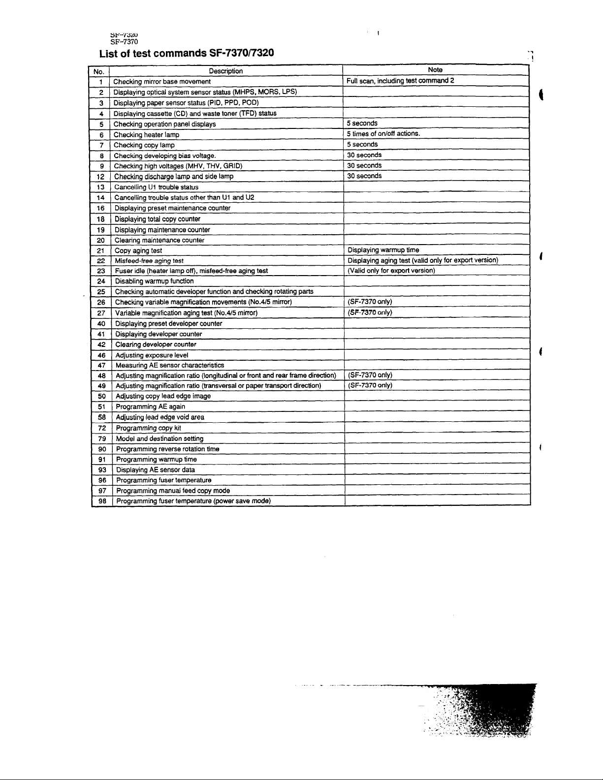
List of test commands SF-7370~320
.7
.!
40.
Description
Note
1
Checkingmirrorbase movement
Full scan, includingtest command2
2
Displayingoptic~ systemsensorstatus(MHPS, MORS, LPS)
3
Displayingpaper sensorstatus(PID, PPD, POD)
4
Displayingcassette(CD) and waste toner (TFD) status
5
Checkingoperationpanel displays
5 seconds
6
Checkingheaterlamp
5 timesof otioff actions.
7
Checkingcopy lamp
5 seconds
8
Checkingdevelopingbias voltage.
30 seconds
9
Checkinghighvoltages(MHV, THV, GRID) 30 seconds
12
Checkingdischargelampand sidelamp
30 seconds
13
Canceling U1 troublestatus
14
Cacelling troublestatusotherthan U1 and U2
16
Displayingpresetm~ntenance counter
18
Displayingtotalcopycounter
19
Displayingmaintenancecounter
20
Clearing maintenancecounter
21
Copy aging test
Displayingwarmuptime
22
Misfeed-freeaging test
Displayingagingtest (valid onlyfor exportversion)
23
Fuser idle (heater lamp o~, miafeed-freeaging test (Valid onlyfor exportversion)
24
Disablingwarmupfunction
25
Checkingautomaticdeveloperfunctionandcheckingrotatingparts
26
Checkingvari~le magnificationmovements(No.415mirror)
(SF-73700nly)
27
Vtiable magnificationagingtest (No.~5 mirror)
(SF-7370 only)
40
Displayingpresetdeveloperwunter
41
Displayingdevelopercounter
42
Clearina develooercounter
4 6
Adjustingex~sure level
47
MeasuringAE sensorcharacteristics
48
Adjustingmagnificationratio(Iongitudindorfront and rear frame direction) (SF-7370 only)
49
Adjustingmagnificationratio(transversalor paper transpotidirection)
(SF-7370 only)
50
Adjustingcopylead edge image
51
ProgrammingAE again
58
Adjustingleadedge voidarea
72
Programmingcopykit
79
Model and destinationsetting
90
Programmingreverserotationtime
91
Programmingwarmuptime
93
DisplayingAE sensordata
96
Programmingfusertemperature
97
Programmingmanualfeed copy mode
98
Programmingfuser temperature(powersave mode)
-. .-—.-.-——----. ..
Page 2
SF-7320
SF-7370
Tv~es of test commands and their functions
- , ~ - —- --—- ------.-—..—— —.
Test command
Function
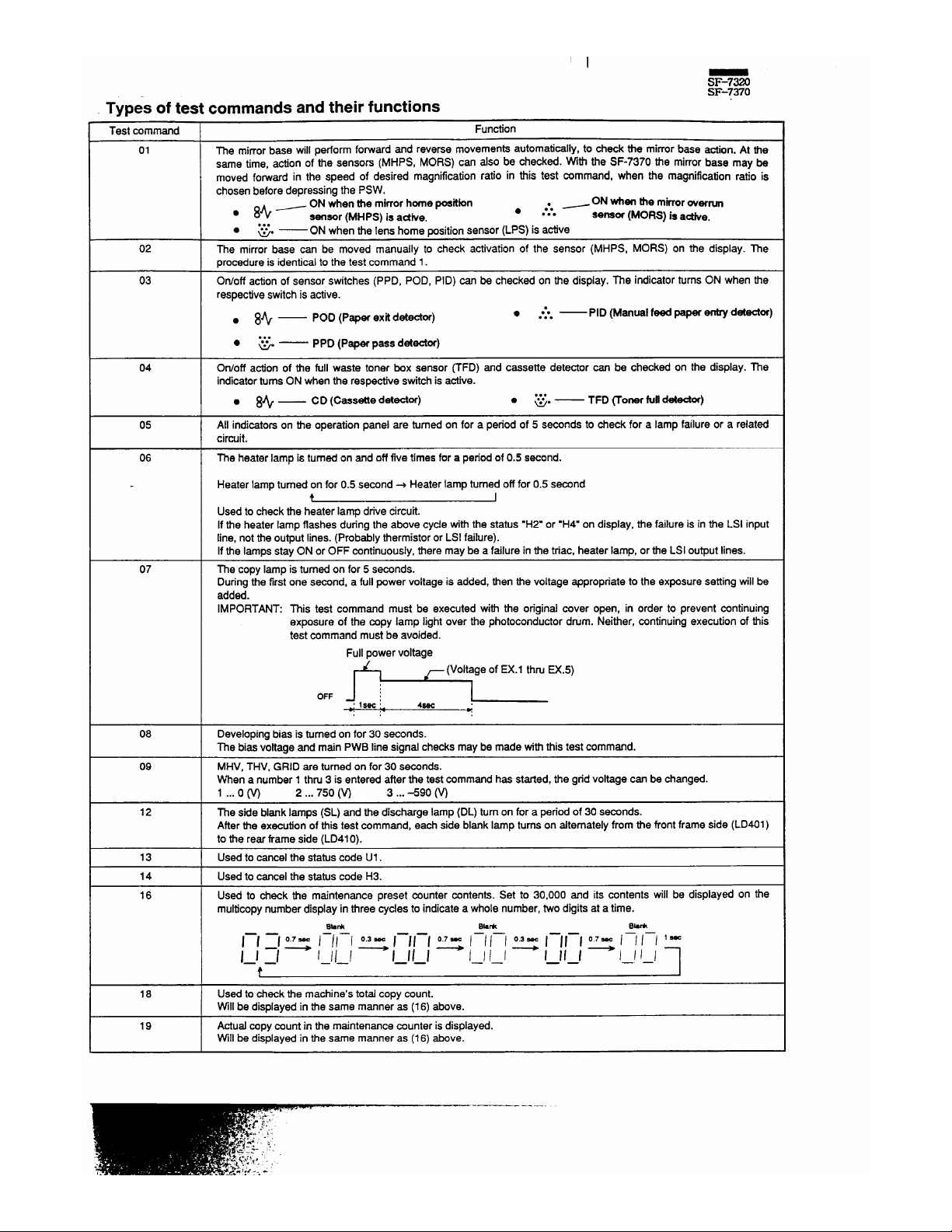
01
The mirrorbase will pedorm fo~ard and reverse movementsautomati~lYt to check tie mimerbase action. At the
same time, actionof the sensom (MHpS, MORS) can also be check~. ~~ the SF-7370 the mirrorbase may be
moved forwardin the speed of desired magnificationratio in tiis test ~mmand, when the magnificationratio is
chosenbeforedepressingthe PSW.
~ ON when the mirrorhome poekbn
~, —ON when the
mirroroverrun
. 8+
●
sensor (MHPS) is adke.
. . .
senam (MORS) is astke.
. . .
●
%“
— ON when tie lens home positionsensor(LPS) is active
02
me mirror base can be moved manually to check activationof the sensor (MHPS, MORS) on the display. The
procedureisidenticaltothe test command 1.
03
Otiotf action of sensorswitches (PPD, POD, PID) can be checked on the display. The indicatorturnsON when the
respectiveswitchisactive.
● 8%—
POD (Paper exti d-or)
● ●*O —
. . .
PID (Manuel feed paper em detester)
. . .
●
=.
— PPD (Paper pass detector)
04 Otioff action of tie full waste toner box sensor ~FD) and cassette detector can be checked on the display. The
indicatorturnsON whenthe respectiveswitchis active.
● 8+ —
CD (Cassette detester)
. . .
●
=.
— TFD ~oner fuUdetector)
05 All indicatorson tie operationpanel are turned on for a period of 5 seconds to check for a lamp failure or a related
circuit.
06
The heaterlampis turnedon and offfive timesfora periodof 0.5 second.
Heater lampturnedon for 0.5 second+ Heaterlampturned offfor0.5 second
t I
Used to checkthe heater lamp drive circuit.
If the heaterlampflashesduringthe above cycletith the status “H2. or .H4” on display,the failureis in the LSI input
line, notthe outputlines.(Probablythermistoror LSI failure).
If the lamps stay ON or OFF continuously,there may be a failurein the triac, heater lamp, or the LSI outputlines.
07 The copy lamp is turnedon for 5 seconds.
Duringthe firstone second, a fullpowervoltage is added,then the voltage appropriateto the ex~sure settingwillbe
added.
IMPORTANT: ~is test command must be executed with the original cover open, in order to prevent continuing
exposure of the copy lamp lightover the photoconductordrum. Neither, continuingexecutionof this
test commandmustbe avoided.
Fullpowervoltage
~ (Voltageof EX.1 thruEX.5)
0-
1
4W
::
*
08 Developingbiasis turnedon for 30 seconds.
The biasvoltage and main PWB line signal checksmaybe made withthis test commend.
09 MHV, THV, GRID are turnedon for 30 seconds.
When a number 1 thm 3 is entered after the testcommand has started,the gridvoltagecan be changed.
1 ...0 m 2,..750 (w 3... +90 (w
12
The side blanklamps (SL) and the discharge lamp (DL) turnon for a periodof 30 seconds.
Afterthe executionof this test command, each side blanklamp turnson dtemately from the frontframeside (LD401)
to the reartiame side (LD41O).
13
Usedto cancelthe statuscode U1.
14
Used to cancel the statuscode H3.
16
Used to check the maintenance preset counter contents. Set to 3 0, 0 00 and its contents will be displayed on the
multicopynumber displayin three cycles to indicatea whole number,two digitsat a time.
Bb*
Bk *
Bhk
——
l—l :1 ~ / // / ~ 1–1 1-1 ~ I / / / ~ I–J I–I ~ / / / / ‘ *
——
——
ill
1–1 1–1 – – – – –.
I I I I
I I I I I I 1 –1
——
——
f
18
Used to checkthe machine’stotal co py count.
VVillbe displayedin the same manneras (16) above.
19
Actualcopycountin the maintenancecounteris displayed.
Will be displayedin the same manneras (16) above.
.-—— -.-.-—
Page 3
5F-7W0
Test command
I
Function
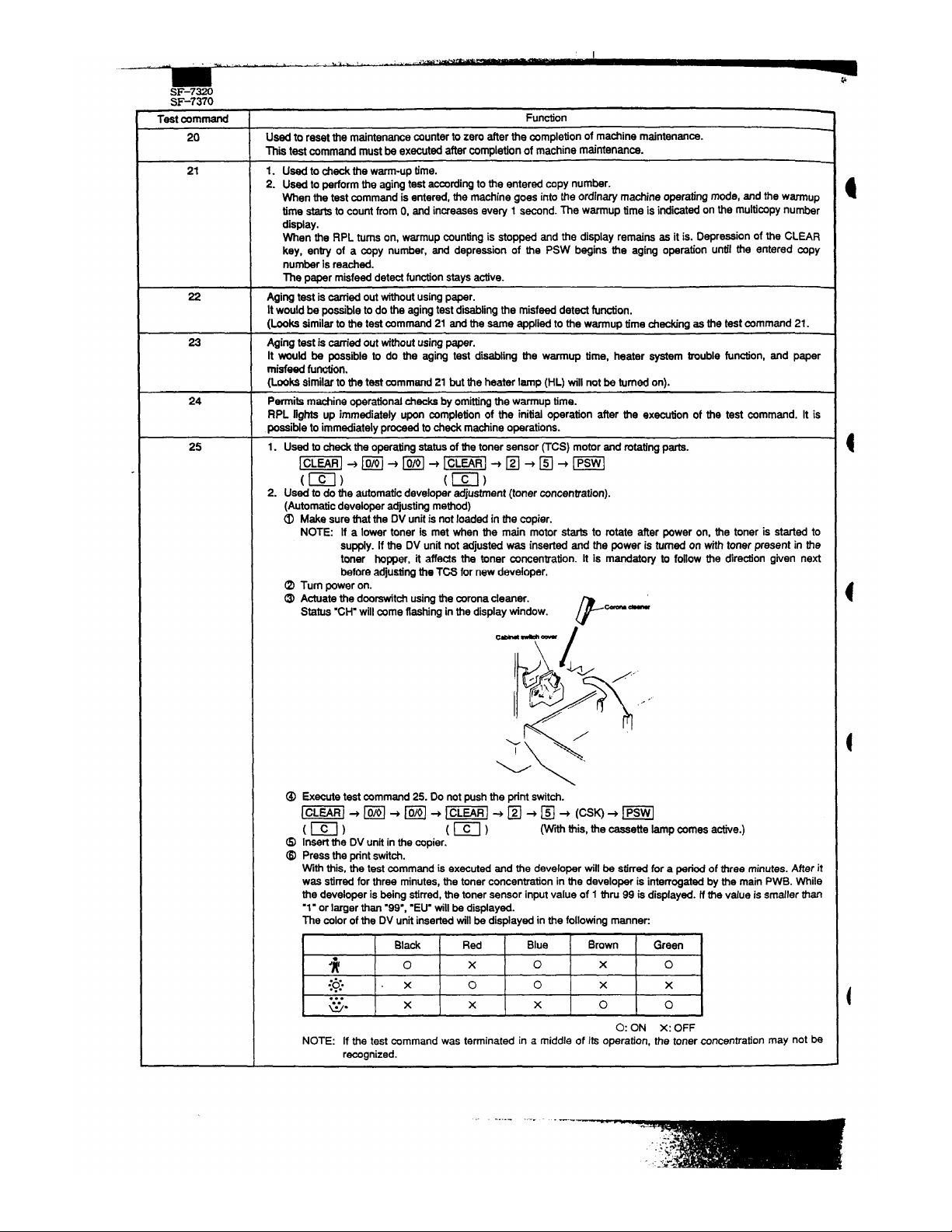
20
Used to resetthe maintenancecounterto zero after the completionof machine maintenance.
This test command mustbe executedaftercompletionof machinem~ntenanCS.
21
1. Used to checkthe warm-uptime.
2. Used to performthe agingtest -rding to the entered copy number.
When the test mmmand is entered, the machinegoes intothe ordinw machine operatingmode, and the wmup
time startsto countfrom O, and increasesevew 1
second.The warmup time is indiated on the muMmPYnumber
dis~ay.
When the RPL turnson, warmupcountingis stopped and the display
remainsasit is. Depressionof the CLEAR
key, entry of a copy number, and depression of the PSW begins the aging operation until the enteredcopy
numberis reached.
The paper misfeeddetectfunctionstaysactive.
22
Agingtestis~ed outtihout usingpqer.
It wouldbe poasi~etodothe agingtestdisablingthe misfeeddetectfu~on.
(tike similarto tie test command21 and the same applied to the warmuptime checkingas the teat mmmand 21.
a
Agingtest is ~.ed out withoutusingpaper.
It WOUMbe possible to do the aging test di~ing the warmup time, heater system trouble funtion, and paper
misfeedfuncdon.
(Lookssimilarto thetestmmmand21 but the heater lamp (HL) wtllnot be turnedon).
24 Pemifs machine operationalti~ks by omitdngthe warmuptime.
RPL nghta up immediately upon completionof the initial operation after the execution of the test command. It is
possibleto immediatelyproceed to check machineoperations.
25
1. Used to checkthe operatingstatusof the toner sensor ~CS) motor and rotatingparts.
%)+~+~+m+D
“D+m
2. Used to do the automaticdeveloperadjustment(tonerconcentration).
(Automaticdeveloperadjustingmethod)
O
Makesurethatthe DVunitis not loaded in the copier.
NOTE: If a lower toner is met when tie main motorstarts to rotate after poweron, the toneris startedto
supply.If the DV unit not adjustedwas insertedand the power is turned on withtonerpresentin the
toner hopper, it affeds the toner concentration. It is mandatory to follow the dire~on given next
beforeadjustingthe TCS fornew developer.
~ Turn poweron.
O Actuatethe doorewitchusingthe coronacleaner.
Status“CH.willcome flashingin the displaytindow.
F
~-
cM --
/
P>\
&J
~,
/,.
‘<
.. ,“’
/
/’
~\
\
~ ~=utetestmmmsnd 25. Do not pushthe printswitch.
w, ~ B + ~ ~ m ~
❑ ~ E ~ (CSW~ m
(Wh this,the cassette lampames a*e.)
0 Insertthe DVunitinthecopier.
@ Presstheprintswitch.
Wth this,
the test command is executedand the developerwill be stirred for a periodof three minutes.After it
was stirredforthree minutes,the toner concentrationin the developeris interrogatedbythe main PWB. While
the developer is being stirred,the toner sensorinputvalue of 1 tiru 99 is displayed.Wme value is smaller than
.1. or lager than “99’, .EU9willbe displayed.
The colorof the DV unitinsetiedwill be displayedinthe followingmanner:
?
Black
Red Blue Brown
Green
*
o
x
o
x
o
:+;.
,x
o 0
x
x
. . .
G.
x x
x
o
0
O: ON X: OFF
NOTE: If the test command was terminated in a middle of its operation,the toner concentrationmay not be
recognized.
Page 4
Test commend
26
(SF-737Oonly)
(SF-7~~0 only)
40
41
—
42
4 6
I
47
SF-737O
Fundon
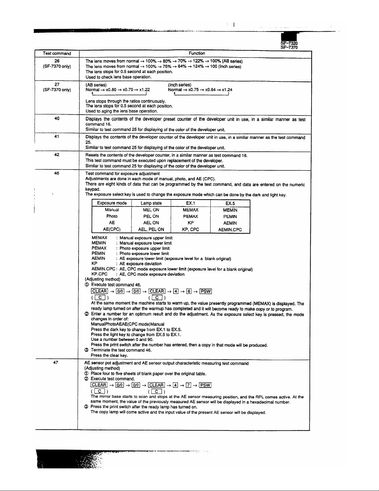
The lens moves fromnormal+ IOOY~+ 80Y0+ 7W14+ l~o + IOOYO(ABseries)
The lens moves fromnorm~ + 100% + 75Y0+ ~VO + 124V0+ 100 (lnChseries)
The lens stopsfor 0.5 secondat each position.
Used to check lens base operation.
(ABseries)
(Inchseries)
No\md + xO.80 + xO.70+ xl.7
Normal+ xO.75+ xO.64+ xl .24
Lens stopsthroughthe ratioscontinuously.
The lens stopsfor 0.5 secondat each position.
Used to aging the
lensbaseoperation.
Displaysthe contentsof the developerpresetcounter of the developerunit in use, in a similar manner as test
command16.
Similarto test command25 for displayingof the colorof the developerunit.
Displaysthe ~ntents of the developercounterof the developer unit in use, in a similarmanner as the test command
25.
Similarto test command25 for displayingofthe colorof the developerunk.
Resets the contentsof the developercounter,in a simila manner as testcommand16.
This test commandmustbe executed uponreplacementof tie developer.
Similarto test command25 for displayingofthe colorof the developerunit.
Testmmmand for exposureadjustment
Adjustmentsare done in each mode of menuaf,photo,and AE (CPC).
Thereare eightkindsof data that can be programmedby the test command,and data are enteredon the numeric
keypad.
Theexposureselect key is usedto changethe exposuremode whiti can be done by the dark and lightkey.
I
Ex~sure mode Lampstate EX.1
Mmual
MEL ON MEMAX
Photo
PEL ON
PEMAX
AE AEL ON KP
[
AE(CPC)
AEL, PEL ON
KP, CPC
EX.5
MEMIN
PEMIN
AEMIN
AEMIN.CPC
MEMN : Manual exposureupper limit
MEMIN : Manual ex~sure lower limit
PEMAX : Photoe~osure upperlimit
PEMIN : Photoexposurelower limit
AEMIN
: AE ex~sure lower limit(ex~sure level for a blank original)
KP : AE exposuredeviation
AEMIN.CPC: AE, CPC mode exposurelowerlimit(exposurelevel for a blankoriginal)
KP.CPC
: AE, CPC mode exposuredeviation
(Adjustingmethod)
Exeotitetest &mmand 46.
M)+m+ m+ w)+ ❑ +E ~m
At the same momentthe machine startsto warm up, the value presentiyprogrammed(MEMAX) is displayed.The
ready lamp turnedonafterthe warmuphascompletedandit will bme readyto makecopyor to program.
Entera numberfor en optimumresultand do the adjustment.As the exposure select key is pressed, the mode
changes in orderof:
M~udPhotoAEAE(CPC mode)Menud
Press the dark key to change from EX.1 to EX.5.
Pressthe lightkey to changefrom EX.5 to EX.1.
Use a number betweenO and 90.
Press the printswitchafter the number has entered, then a copyinthat modewillbe produced.
Terminatethe test command46.
Pressthe clear key.
AE sensorpot adjustmentandAE
sensoroutputcharacteri~.cmeasuringtest command
(Adjustingmethod)
o Place fourto five sheetsof blankpaper over the originaltable.
~
Executetestcommand.
The mirrorbase startsto scan and stopsat the AE sensormeasuringposition,and the RPL comes adve. At the
same moment,the value of the previouslyme~ured AE sensorwillbe displayedin a hexadecimalnumber.
@ Press the printswitchafter the ready lamp has turnedon.
The copylampwill come active and the inputvalue ofthe presentAE sensorwillbe displayed.
Page 5

-w=”” “““ “’””””“---”
SF-7320
‘1
1
S-7 370
T.. *
-mm.nd
I Function
,=S, -,. ... !-.”
O Adjustthe AE sensoradjustingpoton the main PWB.
Afler me ~py lamp has turned on, adjust the input value between EOH and FOHusin9 me As sensor adjusting
pot. Clockwiseturnof the pot increasesthe inputnumberand vise versa. When the inPutv~ue 1swi~in tie limits,
the cassette lampwill come active.
After the AE sen=r adjustment has complet~. press the print stitch to tian9e to the AE se~or output
characteflsticsmeasurin9mode. If the print switch W* not pressed witiin ten minutesafier tie coPYlamP h=
turnedon, it will automatic~ly change to the AE sensor outputcharacteristicsmeasurin9mode. In the AE sensor
outputcharacteristicsmeasuringmode. the COPYlamp drive voltage automaticallyshiftsand the AE sensor output
characteristicsof thattime is automati~lY measured and stored in the memory.
If the adjustmentwas not finished within ten seconds, press the print switch once again after the ready lamp
turnedon and make adjustment.
Q Terminate tie test command47.
CLEAR key (twice)
Vertid (towardsfrontand rear frame sides) magnificationratioadjustingtestcommand
(SF-73$0 only)
me magnificationratiotowardsthe vertid
CO PYdirection(frontframeandrearframe)canbe adjustedbyvaryingthe
lens stopposition.(SF-7370 only)
(Adjustingmethod)
a Place the scale on the originaltable alongthe frontand rear frame sides.
a
Execute testcommmd 43.
1~~ + ~ + ~ + %; + ❑ + ❑ + m
At the same moment the machine starts to warm up, the present value between 2 and 9 will be displayed. After
the warmuphas completed,the ready lamp turns on
andCOPYbe~mes enal~.
~ Make a normal(xI.0) copy on an A4 (814”x 11.) paper.
~ comp~e the size of the sde image on the copy with the astual scale size and obtain the vetial magnification
ratiousingthefollowingformula.
Verticaldirectionmagnificationratiocompensationrate [O/.]=
(size of original) - (size of scale on the copy) ~ ,00
(size of original)
o Use the followingformulato obtain the vedcd magnificationratio preset value.
Vertid magnificationratiopresetvalue = previousvalue (the number shownin (2) above) + verticalmagnification
ratiocompensationratex 10
Q Programthe presetvalue.
m+m
When the presetvalue is changed by “ln, the magnificationratiochanged0.170.
~ Make a normal (x1.0) copy end compare the scafe image withthe scale size.
~ Adjustmentwillbe satisfacto~ ifthe size of the de image on the copy is withinM.8% with respectto the actual
size of tie s~e, if not, repeat the Xove procedures~ thm 0 to adjustit once a9~n.
If the inputnumberwas smaller than .2. or larger th~ “9”,
it may not entile to corr~ the magnificationratiowith
this test command.In suchevent, move the slit plate on the lens
basetowardsthe paperentrysideif smallerMm
‘2”, or, move it towardsthe paper exit side if largerthan “9”.Then, do the adjustmental over again.
~ Terminate the test command43.
CLEAR
Horizontaldirection(towardspapertransportdirection)magnificationratioadjustingtestcommand
(SF-7~~0 only)
me horizontal(papertrans~rt direction)magnificationratiocan be adjustedby varyingthe mirrorbase scan speed.
(SF-7370 only)
(Adjustingmethod)
~ Place the scale over the originaltable along the paper movingdirection.
Q Executetestcommand49.
m)+~ ~ ~+ %)+ E ~~+
m
At the same moment, the machine starts to warm up, tie presentiy programmednumber between 1 ad 99 will
come displayed.The ready lamp comes active after the warmup has completedand it becomes ready to make
a fi”~~ea normal(x1.0) copyon the A4 (81/2”x 11=)paper.
O Compare the size of the sc~e image on the copywiththe actual scale size and obtainthe horfzontd magnification
ratiousingthefollowingformula.
Horizontaldirectionmagnificationratio= J
size of original)- (size of scale on the coPY)~ ,00
compensationrate
IYO] (size of original)
a Use the followingformulato obtainthe Horizontalmagnificationratio presetvalue.
Horizontalmagnificationratiopreset v~ue = previous value (the number shown in ~ ~ove) + horizontal magnificationratiocompensationrate x 10
~ Programthe presetvalue.
n + ~ + Psw
When the
pre se t v ~ue i s changedby “l”, the magnificationratiowillbe changed O.lYO.
a Make a normal(x1.0) copy and compare the scale image with the scale size.
@ Adjustmentwillbe satisfactoryif the size of the scale image on the copy is withinM.8Y0 with respectto the aCtu4
size of the scale. If not, repeat the above procedures~ thruO to adjustit once a9ain.
-—.
Page 6

I
I
SF-73 2 0
Test mmmartd
50
SF-7370
Function
Q Terminate the test command 49.
CL~R
Copy lead edge image positionadjustingtest commend
Adjustmentis done by changingthe RRS on timing so that the image of the originalmaybe copied ontoappropriate
Iooationof the copypaper.
Before startingthe test mmmad 50, be sure to check tie hoflzontd magnification
ratioif appropriate.If not, do the
test command49 to adjustthe magnificationratio.
There are some differencesin the adjustmentproceduresbetweenthe SF-7320 ad the SF-7370.
(Adjustingmethod)
(SF-7320)
O
placethescaleovertheodgind tablealongthepaper movingdirection.
@ Executetestcommmd 50.
%)+ ~ ~ B ~=, ~ R + ~ ~ m
At the same momentthe machinestartsto warm up, the presentlyprogrammednumberbetweenO and 99 will
be displayed.
Descriptionof RRS-a: After completionof the warmup,the ready lamp till come active and become ready to
make a copy.
~ Programthe RRS-ato .O=.
~+~
o Pressthe printswitchand make a copy.
6 Measurethedistancebetweenthe leadedgeof the paper and the lead edge of fhe image onthe copy.
O Obt~n the value of RRS-a.
If the value measuredin~ is assumedto be L1;
RRS-a = 2.778 x L1 + 6.944
Unitin mm, rounded.
a Enterthe value of RRS-a obtained in ~.
0+0
~ Make a copy end make sure that the lead edge image loss is withinthe limits of -2.5+1 .5mm. If not, change
the value of RRS-a and do adjustmentsothat it maybe withinthe limits.
o Terminate the test command 50.
CLEAR
(SF-7370)
~ Place the sde over the
origin~tablealongthepaper movingdirection.
Q Executetest command50.
%)+ m ~m” =, ~ E ~ m ~m
At the same momentthe machinestarts to warm up, the presentlyprogrammednumber betweenOand 99 will
be displayed.
Descriptionof RRS-a: After completionof the warmup,the ready lamp willcome active and become ready to
make a copy.
~ Programthe RRS-ato “O”.
~.~
O Turn the paper selecf key on.
The cassette lamp turned active changes to blink and the presentiy programmednumber between O and 99
will
bedisplayed.
Descriptionof RRS-b
Q Programthe RRS-b to “On.
~+~
@ Make one each of CO PY in the norm~ (xI.0) and reductionmode (xO.64),and measure the distancebetween
the copy lead edge and the sde image lead edge.
Obtainvalues for RRS-a and RRS-b.
L1 = distance between the copy paper lead edge and tie scale image lead edge in the normal(x1.0) mode.
L2 = distance between the copy paper lead edge and the scale image lead edge in the reducdon (xO.64)
mode.
Substitutethe values of L1 and W into the followingformulateto obtain RRS-a and RRS-b.
RRS-a = 7.716 x (Ll - L2)
RRS-b = ((11.574X
L2) - (7.407X Ll)) + 60.417
Unit in mm, rounded.
Turn the paper select key on. The blinkingcassettelamp changes to permanenton.
Programthe value of RRS-a that obtainedina.
O+n
Programthe value of RRS-b thatobtainedin a.
Paper select key (cassettelampon $ blink) m + m
Make a copy in the normal (xl .0) mode and make sure that the lead edge image
IOSS is within -2.5*1 .5mm. If
not, change the value of RRS-b and do adjustmentso that it may be withinthe limits.
Terminate the test command 50.
CLEAR
Page 7

,. . .- +- ~.&H.LL . .
SF-7320
SF-7370
58
72
79
.—-u.:, ’ ‘“ “’.”’
1
1
Function
Copy lead edge void area adjustingtest rwmmand
ne void ~ea width at the copylead edge is adjustedby varyingthe GRID on timin9.
This test commandmust be executed atier the COPYlead edge IOcatiOnhas been COmPletti usingthe teStcommand
50.
(Adjustingmethod)
O Place the sde and a blarrkpaper on the originaltable.
I
,
@
u:
Sde
.........
........
Executetest command 58.
,W)+E+ ❑ +m
At tie same moment the machinestartsto warm up, the presentiyprogrammednumberbetween 1 ~d gg willbe
disnlaved.ne readv lamp comes active after the warmuphas compiet~ ~d ~omes ready to m~e a ~PY.
O ihe~ normal (x1.6) copy withme oflginalcover Ieti open.
o Entera number and make adjustment.
Increasingthe numbermakes the voidarea wider and tice versa.
By changingthe numberby “1”willchange the void area by about0.12mm.
Q Terminatethe test command
58.
CLEAR
Copy tit programmingtest command
(Prooramminamethod)
6 ~xecute t~stcommand 72.
=~+m+~+=;+~+
E+m
At the same moment the ready lamp comes active, tie presently programmednumber between 1 and 4 will be
displayed.
Entera numberto select the copy kitoutofthe table below.
=.B
Wth this,the numberis storedin the memoryand the readylampturnsoff.
Parameter
Developerlamp DML active after
Maintenancelamp DRL active afier
Black
Color
Mini-maintenance
Norrnd maintenance
1
30000 copies
5000 copies
10000 copies
30000 copies
2
30000 copies
5000 wpies
15000 wpies
30000 mpies
3
30000 copies
5000 copies
30000 wpies
30000 copies
4
Does not turn on
5000 copies
Does notturnon
Does not turnon
~ Terminatetie test command 72.
CLEAR CLEAR
Programmingmodeland destination
(Programmingmethod)
~ Executet~st command79.
l=!+ ~ ~ ~ ~
I=;~❑ +❑ +m
At the same timethe ready lamp turnsactive,the presentlyprogrammd numbertill be displayed.
~ Select and enter a number appropriatetothe modeland destinationfromthe table below.
U+m
Pressthe pdntswitchto storethe numberin the memow. The ready lampturnsoff.
SUK
AB series
SEC
Inchseries
Indonesia
exceptSUK
exceptSEC
SF-7320
1
5
6
7
25
SF-7370
11
15
18
17
35
0 Terminatethe test command79.
CLEAR CLEAR
.
Page 8

——— ‘
SF- 78 2 0
SF- 7W0
T.. + - m m . &
I Funcdon
,g-! . . . . . . .. .
90
used to programthe drumcleaning rode. (Main motor reverse rotationperiodprogrammingafterthe completionof
copyoperation)
Afterthe testcommandhas executed,“109till
be displayti for tie lo-smnd modeor ’60=forthe60-second mode.
Press the paper select key to change it from 10 to 60 men to 10 a9ain, which will bS displayedin the multicopy
window.To select the mode, press the printswitch.
91 Usedto programtie warmupmode. (Man motorrotationm~e pqr~ming duringthe heat rollerwarmup)
Aftertie test commandhas executed,the presentlyprogrammedwarmupmodeis displayedin the multicopytindow
intermsof a number.
Select the mode numberto be used usingthe 1,0 key and press the printstitch to set tie mode.
Number
Warmup mode
o
Norm4 mode
1
Man motorrotationsbeforethe heater warmupterminates.
96
Used for seting the tising temperature.
, ; <-. ; ~ :
When this commandis executed,the lowertwo digitsof the currenttyset fusingtemperatureare displayd. (=ample:
75= means 175
degreesCentigrade.)
Underfhh state, push the paper select key, and the fusing temperature will be changed by 5 degrees. Repeat
pushinguntilthe desiredtemperatureis obtained.
97 Used to selectwhetherthe manualcopymodeis startedautomatidly or by pushingthe PSW.
Method:
1) When this test command is executed, the cumentiystored msnu~ copy mode parameter (see table below) is
displayedand the readylamp turnson.
2) Afterthe ready lamp turnson, enter the parameter using
a figureOor 1 forthe mode to be set. Depress the PSW
and tie parameter is men storedinthe memow and me ready lamp goes out.
Parameter
MarruAcopy mode
● Invalid when the multi-bypassstatier is
o
Autostartmode
instiled. (Copy starts after depressionof
1 PSW
startmode
the PSW, when the multi-bypassstacker
is installed.)
98
Used for settingthe fusingtemperaturein the power saving mode.
When this command is ex~uted, the lower two digits of the currentiyset fusingtemperaturein the power saving
mode are displayed.
Under this state, push the paper select key, and the fusing temperature will be changed by 5 degrees. Repeat
pushinguntilthe desiredtemperatureis obtained.
/ 5-0 — ‘ ~~
Page 9

5F-7370
4. Self-diagnostic functions
When the copiermdfundions, operationswe suspendedimmediatelyand a statusmde is indicated on the multimpynumber display,Statuscodes
are representedas an alphanumericmmbinationof figures.
t
t
1
#
I
I
1
‘ “ ” ’ ” -)I‘-, –
I
I
L
{L
~a y~e ddw
*
-----------------------
I
Smh t=hnkian shouM m~e tie sw& 41 wti Hssary
seMm pm on the beebrof the !rouMestatusreportedby the user.
(2) Status code
Status
males willbe displayed on the copy numberdisplaywindowin
the manner shown.
~ CH, L1, L3, L5, H2, H3, H4, Ul, U2, U3, EE
When one of the test status-s L1, L3, L5, H2, or H4 is
indbtad, it maybe cleared by turningthe power off.
When statusU1 is irrdtited, it maybe ckarad by test
timmand 13.
When statusde CH or PC is indhted, it maybe cleard
automa*l& uponmm~tion of troubkshootiq, wthout
entting a test Hind.
When statusde H3 is indkted, h maybe ckared by test
mmmand 14.
@ PC, P flum on), EL, EU
——
Ahaysdi~layedas: f–’;
Bh*
l-if -l ~ /–J /–/ 0 .5 s-
1—1 1—1
1–1 1–
I
9-10
.-.-,-----———
.--..----—.--—-..”---
—-
Page 10

I
SF- 73 2 0
SF- 73 7 0
status
TroublesyMPtOM
[ Mirrorbase feed trouble
● If the mirrorhome ~sition sensor (MHPS) did not
turn off within one second after the start of the
mirror.
L1
I
● If the mirror base forward movement was not
completedwithinten secondsafter the start of the
I mirrorbase.
I
Q[f the mirror base was not on the MHPS position
when the mirror base staded to move forward
duringcopying.
~Mirrorbase returntrouble
L3
● If the MHPS did notturn on withinsix seconds after
the mirrorbase startedto return.
Magnificationratedtrouble(lens, No.4J5mirror)
L5
● If it did not move to the given locationwithinfifteen
secondsafterthe lens motorstartedto operate.
HZ
Open heat rollerthermistor
H3 Heat rollerirregularlyhightemperature
Heat rollerirregularlylowtemperature
“
If tie heat roller temperature did not reach the
H4
prescribedtemperature within the given time after
the start of the heat rollerwarmupoperation.
I
● If an irregularly low temperature was met afier
reachingthe prescribedtemperature.
U1
I Low memo~ backup batteryvoltage
U2
Backupmemorycountersumcheckerror
AE sensortrouble
U3
- If the AE sensor output voltage did not change in
regard to the wpy lamp voltage in test command
4?.
I TCS (Toner controlsensor)inputtrouble
EE
I
● The TCS level was obtained and stored in the RAM
by the test command 25, but the value obtained is
o~t of the limits.
EU
If the TCS input voltage by test command 25 is
above the limit.
-. If the TCS input voltage by test command 25 is
EL
CH
Pc
P (blink)
underthelimit;
DVunitnot installedor poorconnectorinsertion.
Person4 counter not installed for the machine
programmedforthe personal@unter.
During the time cassette feed or multi-bypass
stacker is used, if the PPD (paper entry sensor)
failed to turn on (paper empty or misfeed)withinthe
given time after the paper feed solenoid (CPFS,
MPFS) have turned on.
P
I If the cassettewas notinstalledon itsgiven location.
------- . .
. ---- .-
-. -.: ‘-.,-2-
““”
 Loading...