

Page 1

SF-2540
CODE: 00ZSF2540/A1E
MODEL SF-2540
MODEL SF-D23/D24
MODEL SF-DM11
[Note] The SF-2540 is a minor change model of the SF-2040. This Service Manual omits descriptions
common with the SF-2040, and describes onl y the different points of the SF-2540. For the different
points, refer to the list of changes between the SF-2040 and the SF-2540.
CONTENTS
[ 1 ] PRODUCT OUTLINE . . . . . . . . . . . . . . . . . . . . . . . . . . . . . . . . . 1-1
[ 2 ] PRODUCT SPECIFICATIONS . . . . . . . . . . . . . . . . . . . . . . . . . . 2-1
[ 3 ] OPTIONS SPECIFICATIONS . . . . . . . . . . . . . . . . . . . . . . . . . . 3-1
[ 4 ] COMPONENT IDENTIFICATION . . . . . . . . . . . . . . . . . . . . . . . 4-1
[ 5 ] INSTALLATION . . . . . . . . . . . . . . . . . . . . . . . . . . . . . . . . . . . . . 5-1
[ 6 ] DISASSEMBLY AND REASSEMBLY . . . . . . . . . . . . . . . . . . . . 6-1
[ 7 ] ADJUSTMENTS . . . . . . . . . . . . . . . . . . . . . . . . . . . . . . . . . . . . . 7-1
[ 8 ] SIMULATION AND DIAGNOSTICS . . . . . . . . . . . . . . . . . . . . . . 8-1
[ 9 ] MAINTENANCE AND OTHERS . . . . . . . . . . . . . . . . . . . . . . . . . 9-1
[10] ELECTRICAL SECTION . . . . . . . . . . . . . . . . . . . . . . . . . . . . . 10-1
Parts marked with "!" is important for maintaining the safety of the set. Be sure to replace these parts with specified
ones for maintaining the safety and performance of the set.
This document has been published to be used
SHARP CORPORATION
for after sales service only.
The contents are subject to change without notice.
Page 2
SF-2540
List of changes between the SF-2040 and the SF-2540
No.
Page Item Content Change
I CONTENTS [3] OPTIONS SPECIFICATION
II CONTENTS [4] COMPONENT IDENTIFICATION
[5] INSTALLATION
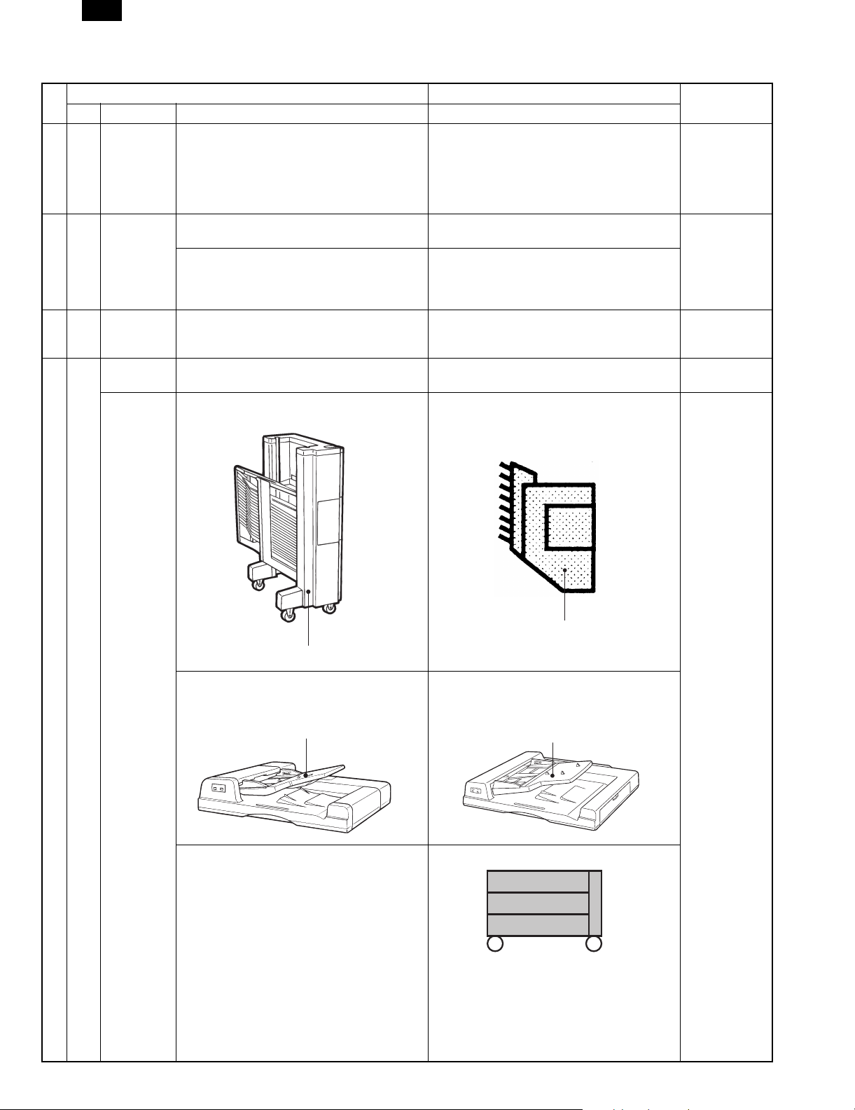
III CONTENTS (2) SF-A55 . . . . . . . . . . . . . . . . . . . . . (2) SF-A55 is changed to SF-A58.
1-1 [1]-1 1. General description
The SF-2040... "The SF-2040" is changed to "The SF-2540."
[1]-4 System outline • The model name and the illustration are
SF2040 SF2540
1. SF-A55 . . . . . . . . . . . . . . . . . . . . . . . 1. SF-A55 is changed to SF-A58.
2. SF-S15 . . . . . . . . . . . . . . . . . . . . . . .
3. SF-S53 . . . . . . . . . . . . . . . . . . . . . . . 3. SF-S53 is changed to SF-S56.
4. SF-D23 . . . . . . . . . . . . . . . . . . . . . . . 4. SF-D23 is changed to SF-D23/D24.
5. Others . . . . . . . . . . . . . . . . . . . . . . . .
9. Desk unit (SF-D23) . . . . . . . . . . . . . . (SF-D23) is changed to (SF-D23/D24).
A. Installing conditions . . . . . . . . . . . . . .
B. Installation procedure . . . . . . . . . . . .
(1) SF-2040 . . . . . . . . . . . . . . . . . . . (1) SF-2040 is changed to SF-2540.
(3) SF-S53 . . . . . . . . . . . . . . . . . . . . . (3) SF-S53 is changed to SF-S56.
(5) SF-D23 . . . . . . . . . . . . . . . . . . . . . (5) SF-D23 is changed to SF-D23/D24.
changed.
Remark
1/bin staple sorter (SF-S53)
Reversing automatic document feeder
(SF-A55)
20 bin staple sorter (SF-S56)
• The model name and the illustration are
•
changed.
Reversing automatic document feeder
(SF-A58)
• SF-D24 is added.
500
(500)
One-step paper feed unit (SF-D24)
1/27/1999 – 1 –
Page 3
SF-2540
No.
Page Item Content Change
SF2040 SF2540
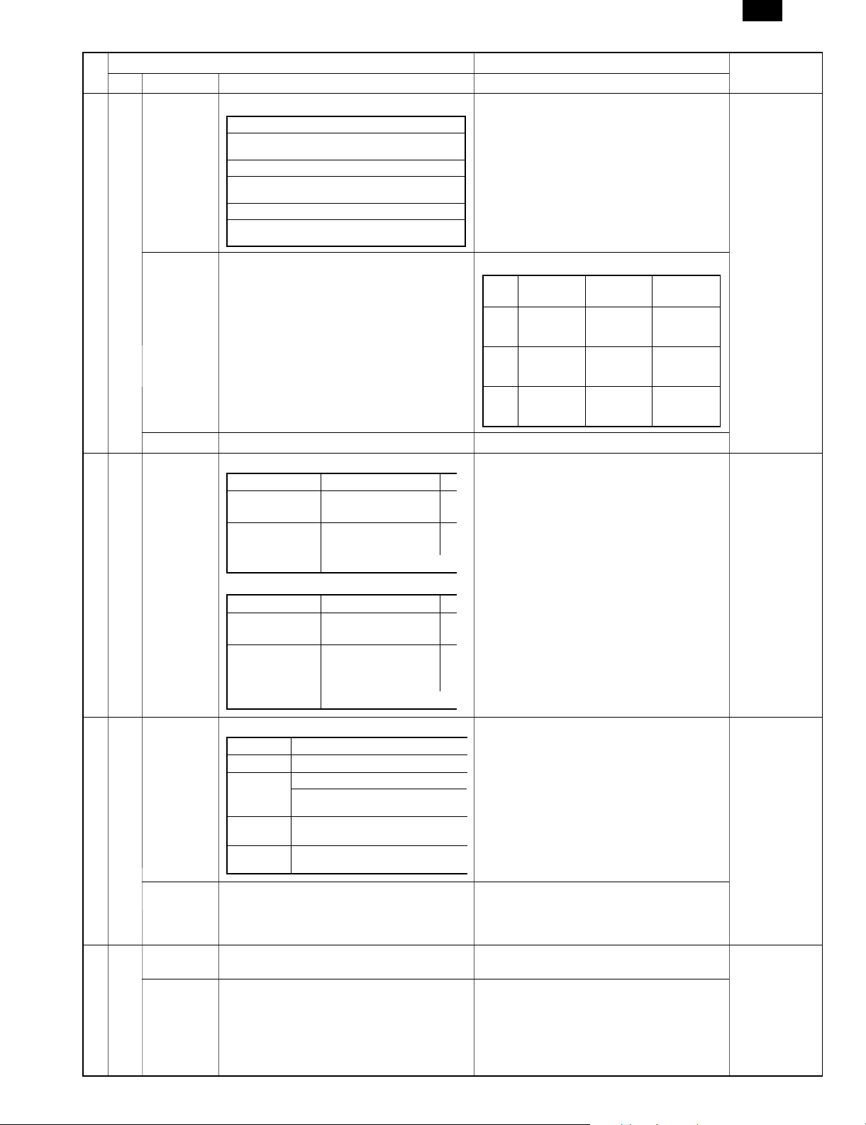
2-1 [2]-1-(3) (3) Kinds of originals
Option: RADF
Original
loading capacity: 50 sheets (30 sheets for A3/WLT) is added to 50 sheet.
Original size: A3 to A5, Ledger ∼ Invoice
Original
replace speed: 40 sheets per minute
Weight of original: 35 to 128 g/m
Mixed paper
feed mode: Possible (same width)
2
(14 to 34 lbs)
[2]-1-(4) (4) Copy Speed Copy speed of China paper is added.
Actual (1:1)
8K 22 sheets
per minute
16K 40 sheets
per minute
16KR 31 sheets
per minute
[2]-1-(5) (5) Warm up time • "Auto power shut off : YES" is added.
2-2 [2]-1-10 AB series AB series
Paper entry Paper size Letter and 13" are added to the paper size
Upper cassette
(Option)
B5/B5/R
A4/A4R/B4/A3
of upper/lower cassettes.
Lower cassette A5/B5/B5R
A4/A4R/B4/A3
A5: * With the option ~
Inch series Inch series
Paper entry Paper feed size A4 and 13" are added to the paper size of
Upper cassette
(Option)
Letter/Letter R/
Legal/Ledger
upper/lower cassettes.
Lower cassette Letter/Letter R/
Legal/Ledger/
Invoice
* With the option ~
Enlarge
(ratio)
19 sheets
per minute
(200%)
33 sheets
per minute
(200%)
27 sheets
per minute
(200%)
Remark
Reduce
(ratio)
16 sheets
per minute
(50%)
21 sheets
per minute
(50%)
18 sheets
per minute
(50%)
2-3 [2]-1-19 (19) Automatic duplex
Option (SF-DM11)
Location Copier upper module slot
Size AB series: A3, B4, A4R, B5, B5R, A5
Inch series: Ledger, Legal, Letter,
Capacity 50 sheets (below A4 or
Paper weight 56 to 80 g/m
Letter R
Letter size)
lbs)
2
(15 to 21
13" is added to the inch series.
(However, 13" area only)
SCA/AB series agents, Inch series agents
[2]-1-(20) (20) Paper receive tray and finishing Model name change
• SF-S53 is changed to SF-S56.
• The capacity of non-sort bin is changed
from 250 sheets to 100 sheets.
2-4 [2]-1-(23) (23) Power consumption 1.5KW is changed to 1.45KW (100V series) or
[2]-1-(24) Weight Weight of about 71.2Kg is changed to about
1.75KW (200V series).
65.8Kg.
– 2 – 1/27/1999
Page 4
SF-2540
No.
Page Item Content Change
SF2040 SF2540
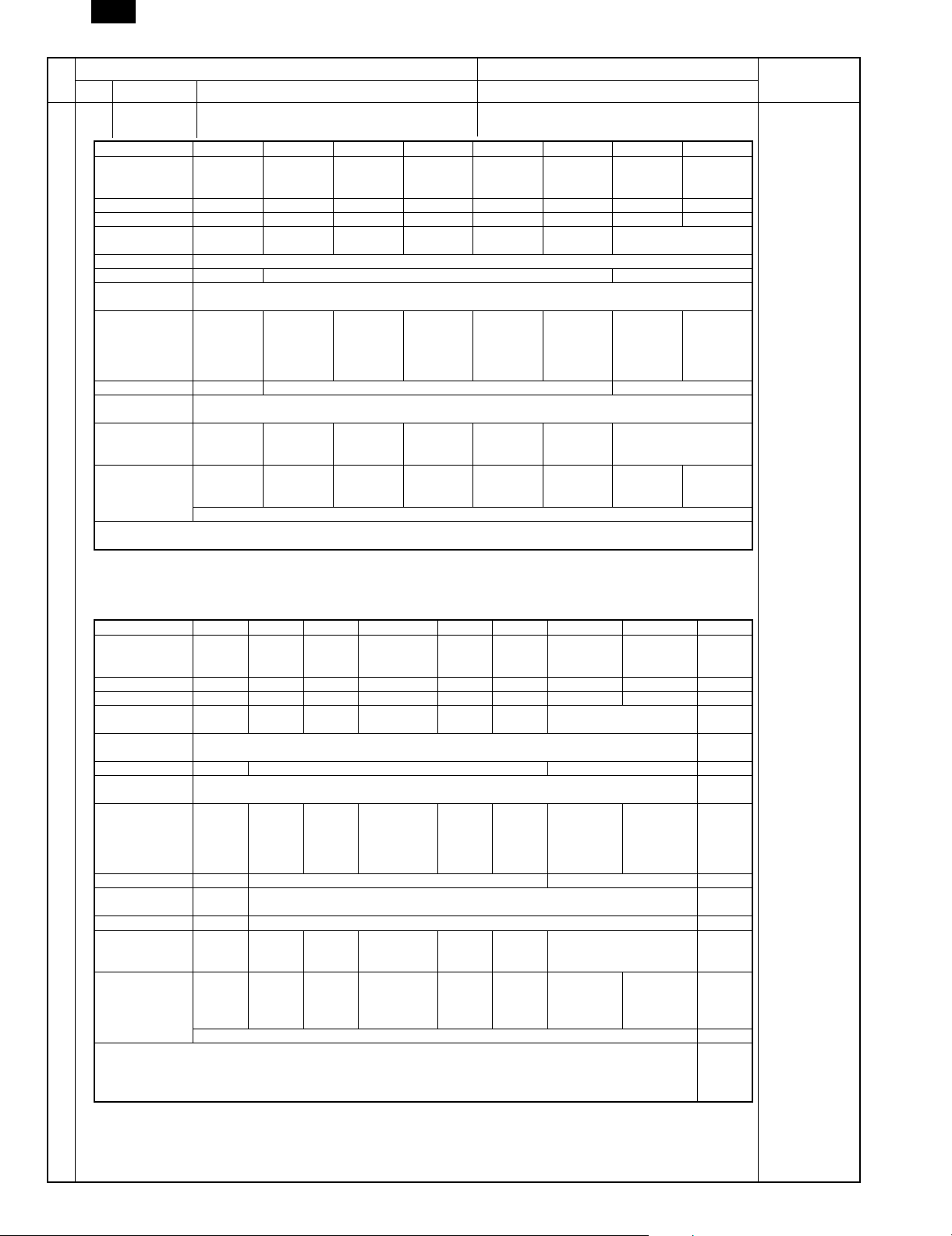
2-5 [2]-25 SF2040
(25) Accessories
Destination Japan SEC SECL SEEG SUK SCA AB agent Inch agent
Drum Installed
Developer (Black) F ✕✕✕✕✕✕✕
Toner cartridge F ✕✕✕✕✕✕✕
Original cover Standard
Paper exit tray 1
Original table ✕ F ✕
Toner collection
container
Operation manual Japanese Exclusive
Dust cover F ✕ F (Part)
Zooming ratio
table
ROM language Japanese English English GG: German
Key sheet Japanese English English
Other printed matters:
Delivery/installation report (Japan/SEEG), SCA warranty, Warranty registration (SUK), Maintenance card, Counter contract × 2 (Japan)
when
shipping.
provision
*1
*1
: Retractable (Japan), Fixed (Outside Japan)
Installed
when
shipping.
Option Option Option Option Option Standard provision
English
Installed
when
shipping.
English
/French
/French
SEL = English/French packed together. SEEG (BG) = Treated in a kit.
Separately
packed.
F (4pcs.) One is installed when shipping.
GG: German
BG: None
BG: None
GG: German
BG: None
Separately
packed.
F
Exclusive
English
F
English English English/French/Spanish
English English English,
Installed
when
shipping.
English English
Partly
packed.
/French
/Arabic
Typical
example
depending on the
partly
Spanish
Remark
Partly
packed.
English
/Spanish
Typical
example
destination.
English,
partly
Spanish
SF-2540 accessory (The changed items are in Gothic.)
(25) Accessory
Destination Japan SEC SECL SEEG SUK SCA AB agents Inch agents China
Drum Installed
Developer (Black) ✕✕ ✕ ✕✕ ✕ ✕ F
Toner cartridge ✕✕ ✕ ✕✕ ✕ ✕ F
Original cover Standard
Paper exit tray
(*1)
Document table ✕ ✕ (LAG package) F
Toner collection
bottle
Operation Manual Japanese Special
Dust cover ✕ F (Part) ✕
Magnification ratio
quick-find list
Paper size label FFF
Language ROM Japanese English English GG: German/
Key sheet
conformity
Other printed matters
Installation manual (Japan, Delivery report: Japan/SEEG), SCA Warranty
Warranty registration (SUK), Maintenance card, Counter contract × 2 sheets (Japan)
Maintenance control table (Chinese), K8/K16 adapter (Only for China)
when
shipping
provision
Japanese English English/
Installed
when
shipping
Option Option Option Option Option Standard provision
English
F ✕✕
Installed
when
shipping
English
/French
French
SEL = English/French packed together. SEEG (BG) = Treated in a kit.
Installed
when
shipping
F (4 pcs) One is installed when shipping. F
GG: German
BG: None
English
BG: English
GG: German/
English
BG: None
attached
Installed
when
shipping
Special
English
English English English/French/
English English English/
Installed
when
shipping
English English
Installed
when
shipping
/French
/Arabic
Typical
example
Spanish depending on the
Spanish
(Some area)
(LAG option)
destination
Installed
when
shipping
English
/Spanish
Typical
example
English/
Spanish
(Some area)
Installed
when
shipping
Standard
provision
F
China
China
Chinese
*1: Extendable for Japan, fixed for EX japan.
1/27/1999 – 3 –
Page 5
SF-2540
No.
Page Item Content Change
2-5
[2]-2 Consumables 2. Consumables change (Refer to the
2-6
SF2040 SF2540
separate sheet.)
• SF-2540 Supply system (SECL, agents)
• SF-2540 Supply system (SEEG, SUK,
SCA, SCNZ)
3-1 [3] [3] OPTIONS SPECIFICATIONS
1. SF-A55
3. SF-S53
3-2 [3] [3] OPTIONS SPECIFICATIONS Model added.
4. SF-D23 4. SF-D24 is added to SF-D23.
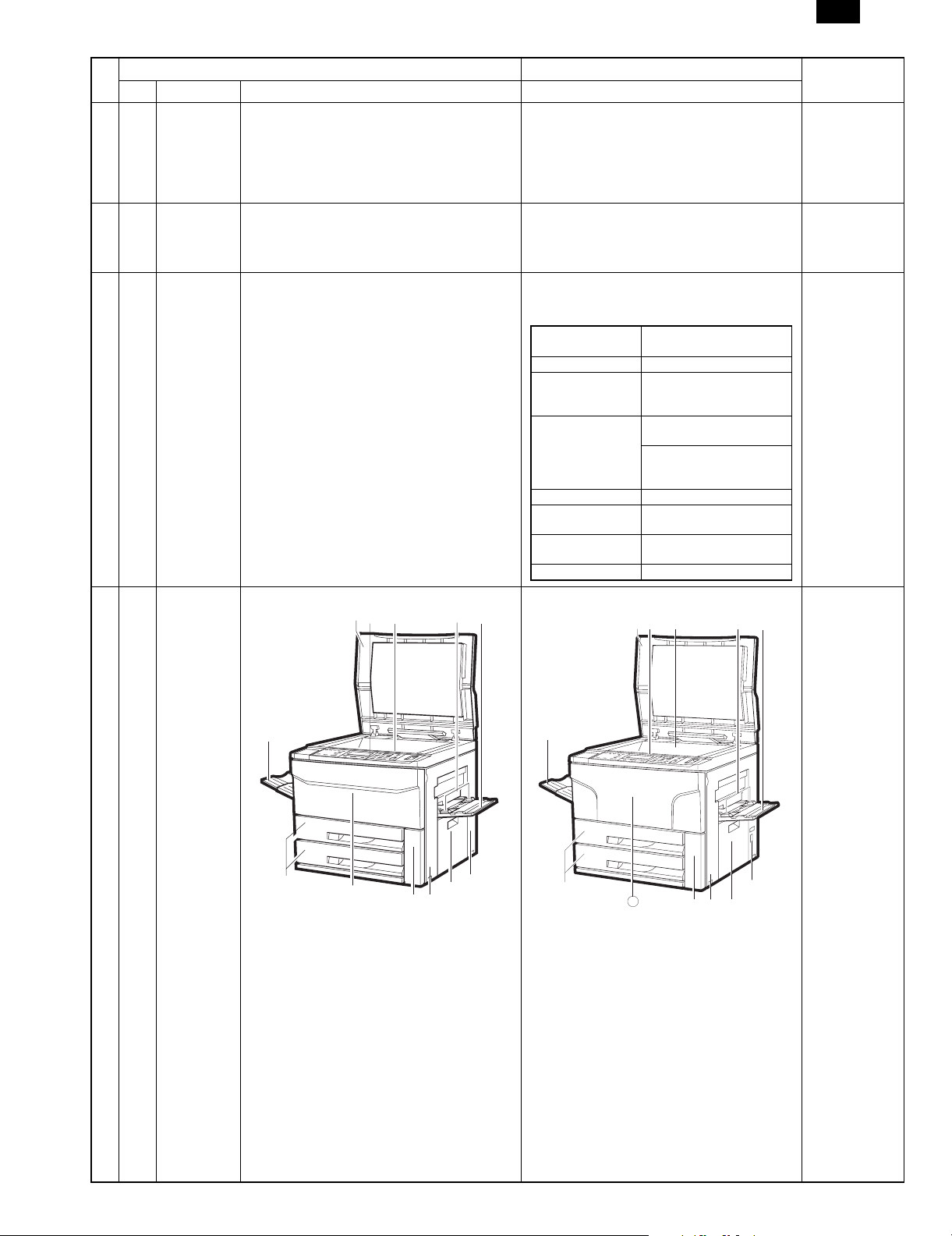
4-1 [4]-1 1. External view I Front cover shape change
Model change
1. SF-A55 is changed to SF-A58.
3. SF-S53 is changed to SF-S56.
One-step paper feed desk <SF-D24>
Number of paper
feed step
Paper feed capacity 500 sheets
When expanded 1000 sheets (500 sheets × 2
Paper size AB series:
Paper weight 50 ∼ 80g/cm
Power source Supplied from the copier.
External dimensions
(W × D × H)
Weight 27.2Kg
1 step (2 steps when
expanded)
steps, with SF-CM11
installed)
A3, B4, A4, A4R, B5, B5R
Inch series:
11 × 17", 8 1/2 × 14", 8 1/2 ×
11", 8 1/2 × 11R
(DC24V)
600(W) × 625(D) × 451(H)
mm
2
Remark
Refer to the
attached sheet
2-5.• SF-2540 Supply system (SEC)
Refer to the
Service Manual
of the
SF-A58/SF-S56.
13
– 4 – 1/27/1999
Page 6

SF-2540
No.
Page Item Content Change
SF2040 SF2540
4-4 [4]-3 Internal view Illustration No. V is deleted.
No. e is added.
List No. V Upper cleaning roller is deleted.
No. e Process mark sensor is added.
41
Added
6
5
20
18 17
19
Deleted
21
27
26
28
25
24
40
21
23 22
4-8 [4]-7 Board list
Name Type
5 Original sensing light emitting PWB Japan
5 6 board types are changed.
Japan → Common
6 Original sensor light receive PWB Japan
4-10 [4]-9 Desk unit (SF-D23) Sensors T U are added to the desk unit.
T Paper quantity sensor (DPTD1)
U Paper quantity sensor (DPTD2)
Remark
3
8
16
97
10
4
12
13
30
29
31
32
34
35
36
33
37
38
1514
39
22
19
20
15
Added
24
14
5-2 [5]-B B. Installation procedure Model name change
(1) SF-2040 SF-2040 is changed to SF-2540.
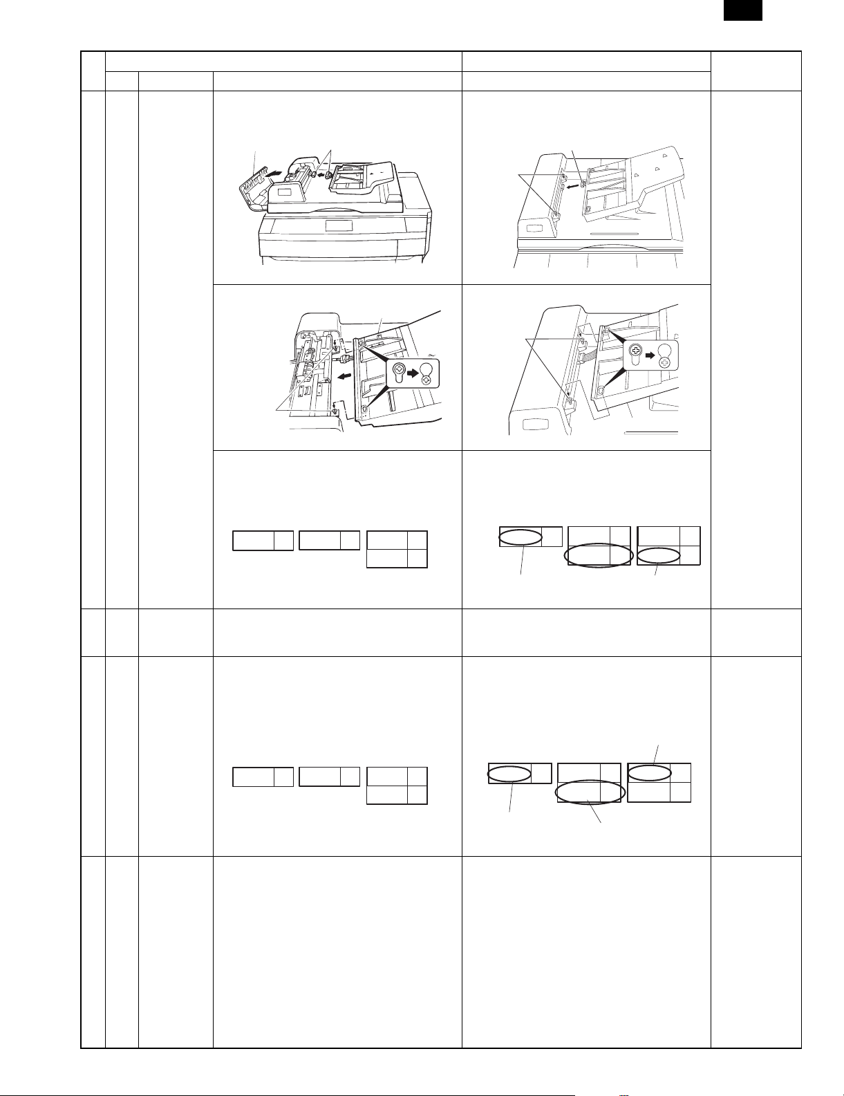
5-10 [5]-B-11-(2) SF-A55 The model name and the illustration are
changed due to model change.
SF-A58
23
Added
25
21
1/27/1999 – 5 –
Page 7
SF-2540
No.
Page Item Content Change
SF2040 SF2540
5-11 [5]-B-11-(2) 4. Connect the ADF tray connector Illustration change (Refer to the following il-
lustration.)
ADF Cover
Connectors
Connector
Mounting
screw
5. Attach the tray Illustration change
Tray
Mounting
screw
Mounting
Screw
6. Set the mode Model name change in the descriptions
• SF-S53 is changed to SF-S56.
• SF-A55 is changed to SF-A58.
• SF-D24 is added.
Remark
Tray
1
SF-A55
SF-S15
SF-S53
10
10
1
SF-D23
4
SF-A55
SF-D23
SF-D24
Changed to SF-S58
5-12
[5]-B-11-(3) (3) SF-S53 Model change
~
SF-S53 is changed t o SF-S56 .
5-18
5-21 [5]-B-11-(4) (4) SF-S15 (20-Bin Sorter) Model change and addition
10. Set the mode SF-S53 is changed to SF-S56.
SF-A55 is changed to SF-A56.
SF-D24 is added.
1
SF-A55
1
SF-D23
4
SF-S53
SF-S15
10
10
SF-A55
SF-D23
SF-D24
Changed to SF-S58
SF-D24 is added
5-29 [5]-B-11-(7) (7) SF-DM11 The following note is added.
9. To check and adjust the matching guide Enter "0" in SIM 52-3. (All destinations except for SEC/SECL.)
4
4
SF-S15
SF-S53
10
10
SF-S56
Changed to SF-S56
4
4
SF-S53
SF-S15
10
10
– 6 – 1/27/1999
Page 8
SF-2540
No.
Page Item Content Change
SF2040 SF2540
6-4 [6]-2 Manual feed multicopy unit Illustration C spring position change
C
6
4
5
8
7
C
6
4
5
8
Spring
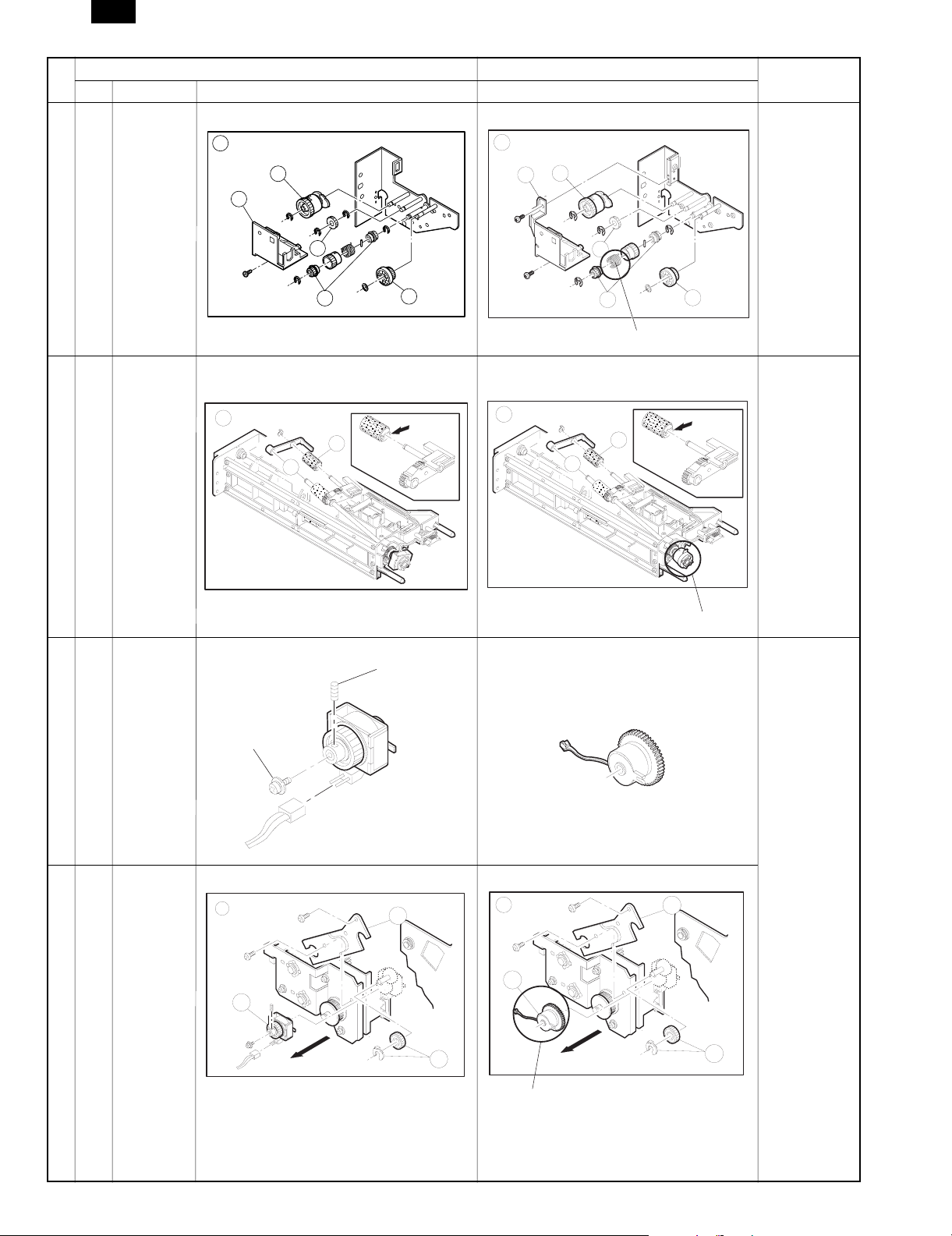
6-6 [6]-3 Paper feed unit Illustration A ~ E clutch shape change (Refer
to C in the figure below.)
C
7
6
C
7
6
Remark
7
6-7 [6]-4 4. Transport baseplate unit Clutch shape change
Set screw
Screw
Connector facing downward
6-8 [6]-4 4. Transport baseplate unit Illustration F clutch shape change
F
12
5
11
F
12
Clutch
5
11
1/27/1999 – 7 –
Clutch
Page 9
SF-2540
No.
Page Item Content Change
SF2040 SF2540
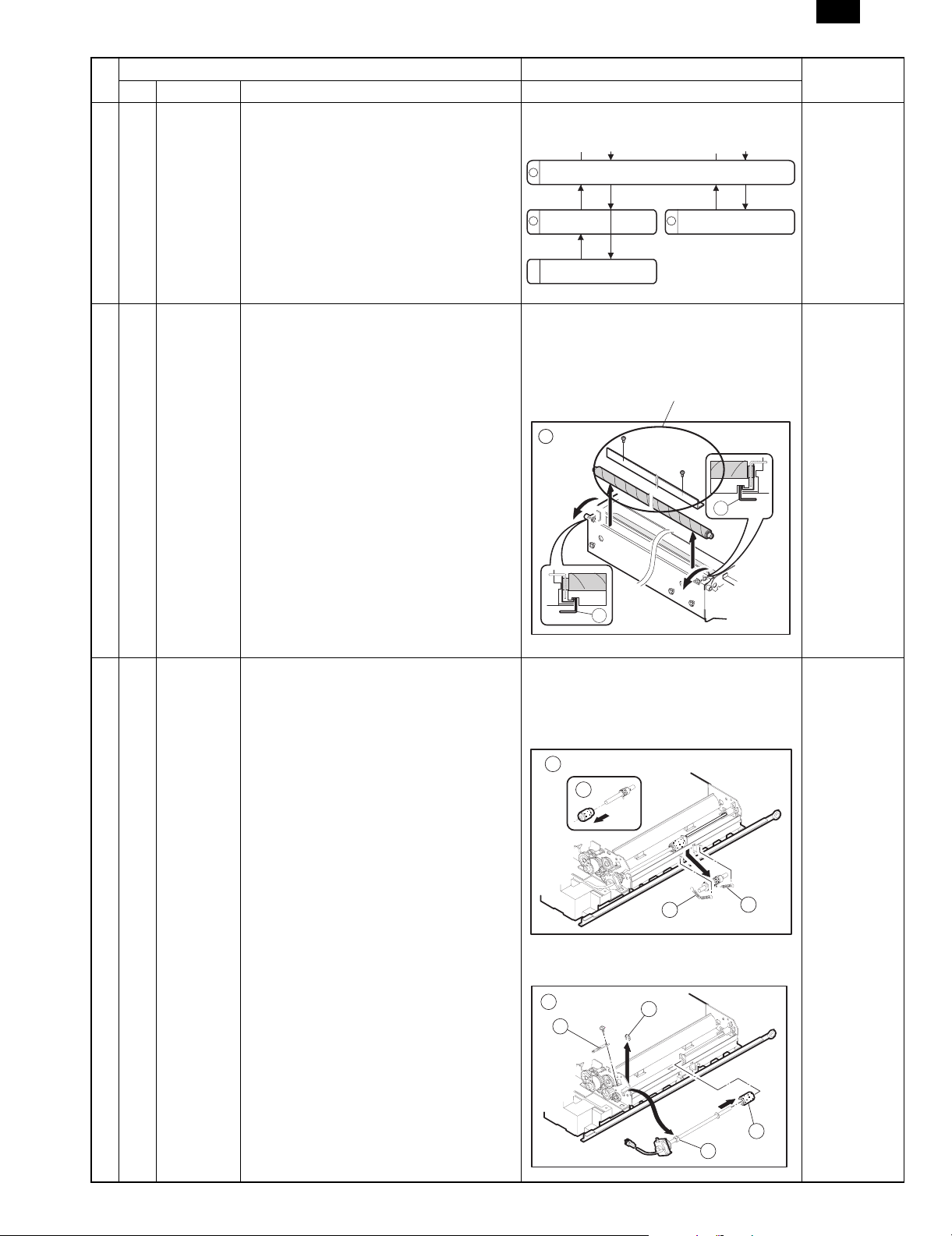
6-9 [6]-5 Fuser unit Flow chart change
2. Procedure to remove the scraper is added.
10
Open the lower pawl holder bracket assy (2 screws).
Remove the lower heat
11
roller assy.
Remove the scraper
6-10 [6]-5 Fusing unit Fusing unit
• Scraper and two screws are added to il-
lustration G.
Control code G is changed to F.
G
Remove the lower
13
separation pawls.
Added
Remark
16
16
6-12 [6]-6 6. Duplex copy unit 6. Duplex copy unit
• Control code E of illustration E is
changed to F. Part No. H is changed
to L, and I to M. (Refer to the figure
below.)
F
17
illustration E is added. (Refer to the figure
below.)
E
12
16
13
16
15
14
– 8 – 1/27/1999
Page 10
SF-2540
No.
Page Item Content Change
SF2040 SF2540
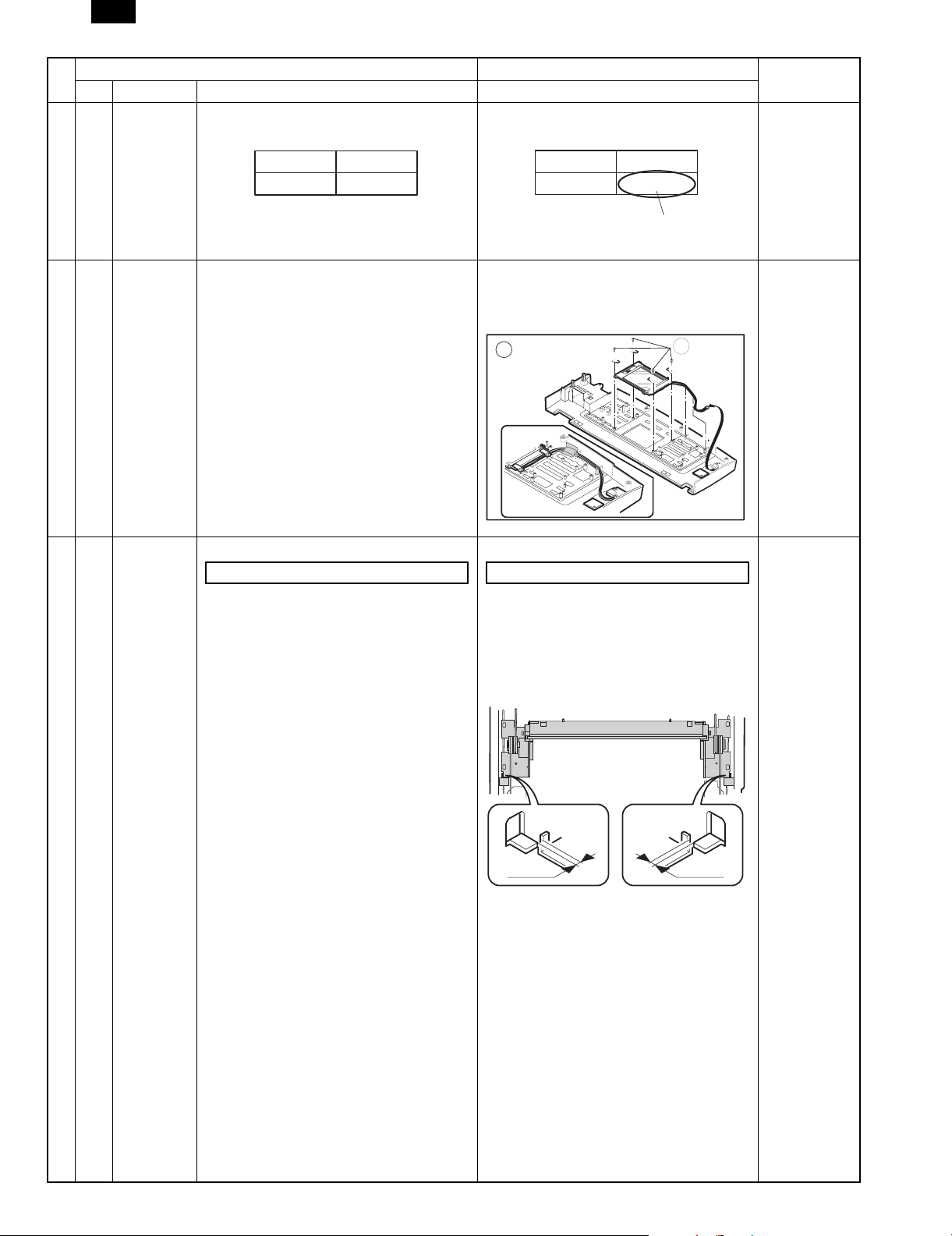
6-15 7. Rear frame side major components Red label is changed to Pink label.
* DC power PWB identification * DC power PWB identification
100V system 200V system
White label Red label
6-16 [6]-8 8. Operation panel unit and document size
sensor board (light receiver side)
8. Operation panel unit and document size
100V system 200V system
White label Red label
sensor board (light receiver side)
• No. G is added to illustration c. (Refer
to the figure below.)
C
Remark
Pink label
11
6-21 [6]-9 9. Optical unit 9. Optical unit
Copy lamp unit installing position Copy lamp unit installing position
The following description and illustrationa re
added.
* When the copy lamp unit is pushed to the op-
tical section notch, there must be a
clearance of 2mm between No. 2/3 mirror
base unit and the optical section notch.
2mm 2mm
1/27/1999 – 9 –
Page 11
SF-2540
No.
Page Item Content Change
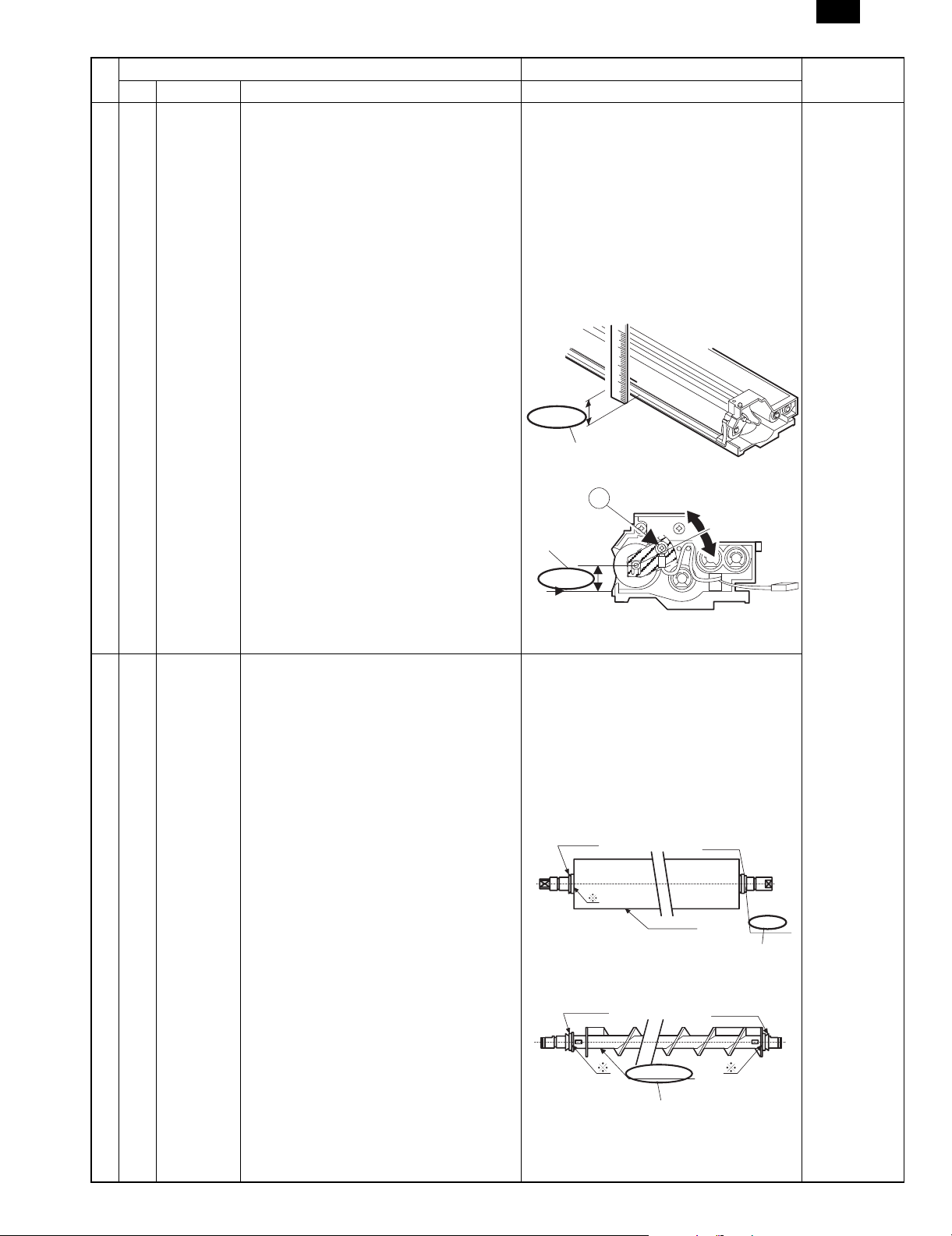
7-1 [7]-1-(2) (2) Position Adjustment of Developing Magnet
SF2040 SF2540
(2) Position Adjustment of Developing Magnet
Roller Main Pole
Roller Main Pole
The measurement value, 17.7mm, in the
description and illustration are changed to
19.1mm.
5 Measure the distance from the mark to the
reference plane on which the developer
tank is placed.
This distance must be 19.1 mm.
If not so, loosen setscrew A of the main
pole adjusting plate and move the adjusting
plate in the arrow direction to obtain the
proper distance.
17.7mm
19.1mm
A
Remark
7-2 [7]-1-(4) (4) Notes on installing various rollers of the
developing unit
19.1mm
17.7mm
(4) Notes on installing various rollers of the
developing unit
• Part codes of φ8 ring and φ6 ring are
changed as follows.
(3) When attaching φ8-ring PRNGP0051FCZZ
φ8-ring and PRNGP0022FCZZ and φ6-ring
PRNGP0050FCZZ to the developing
magnet roller,
• The name in the illustration is changed
and an addition is made.
φ
V-ring 8
Rear Front
Magnet roller
φ
V-ring 8
Cring
(Added)
φ
V-ring 6
Rear Front
Roller S (X2)
Changed to Roller SS (X2)
φ
V-ring 6
– 10 – 1/27/1999
Page 12

SF-2540
No.
Page Item Content Change
SF2040 SF2540
7-2 [7]-1-(4)
φ
V-ring 6
Rear Front
(5) Notes on applying the developing side
seals (front and rear)
(5) Notes on applying the developing side
seals (front and rear)
• Side seal FN/FR shape change (Refer
to the figure below.)
D B
Rear
V-ring 6
Roller MX
Changed to Roller MXS
Remark
φ
Front
7-23 [7]-6-A A. Adjustment when installing the machine A. Adjustment when installing the machine
• Procedures (2)(3) below are added.
(2) Execute SIM 44-2.
Drum mark sensor level adjustment
Standard value: 204 ±10
(3) Execute SIM 44-3.
Image density sensor level adjustment
Standard value: 204 ±10
[7]-6-D D. Adjustment when replacing the drum
(Photoconductor)
D. Adjustment when replacing the drum
(Photoconductor)
• Adjustment procedure (4) is changed to
(5).
• Adjustment procedure (4) is added.
(Refer to the following description.)
(4) Execute SIM 44-3.
Image density sensor level adjustment
Standard value: 204 ±10
[7]-6-E E. Adjustments when replacing the developer
and the drum (photoconductor)
E. Adjustments when replacing the developer
and the drum (photoconductor)
• Adjustment procedure (5) is changed to
(6).
• Adjustment procedure (5) is added.
(Refer to the following description.)
(5) Execute SIM 44-3.
Image density sensor level adjustment
Standard value: 204 ±10
8-1
[8] [8] SIMULATION AND DIAGNOSTICS For [8] SIMULATION AND DIAGNOSTICS,
∼
8-18
9-2 [9]-2 2. Counters and simulation related to
maintenance
(1) List of counters and test commands related
to maintenance
refer to the separate sheet.
2. Counters and simulation related to
maintenance
(1) List of counters and test commands related
to maintenance
List change (Refer to the separate sheet
9-2.)
Refer to the
separate sheet
8-1 to 8-18.
Refer to the
separate sheet
9-2.
1/27/1999 – 11 –
Page 13

SF-2540
No.
Page Item Content Change
SF2040 SF2540
9-6 [9]-4-(5) (5) Paper exit roller driving gears Illustration shape change
9-7 [9]-4-(6) (6) Paper-feed torque limiter 500-sheet
Illustration shape change
cassette brake spring
Remark
Torque limiter
500-sheet cassette brake spring
Brake spring
Torque limiter
– 12 – 1/27/1999
Page 14

SF-2540
2. Consumables
SF-2540 supply system (SEC)
No. Name Content Life Product name Package Remark
1 Upper heat
roller kit
2 Lower heat
roller kit
3 80K maintenance
kit
4 Cleaner
blade
5 Upper cleaning
roller
6 Lower cleaning
roller
7 Staple
cartridge
* For Toner collection bottle (4 pcs, 80K)/Screen grid (80K)/Charger wire (80K)/Ozone filter (80K)/Toner reception seal (160K)/DV seal, use service
parts.
Charging plate unit (120K) and drum separation pawl unit (120K) are supplied as service parts.
SF2540 supply system (SECL, for Agent)
No. Name Content Life Product name Package Remark
1 80K maintenance
kit
2 160K
maintenance kit
3 Staple
cartridge
SF2540 supply system (SEEG, SUK, SCA, SCNZ)
No. Name Content Life Product name Package Remark
1 80K maintenance
kit
2 160K
maintenance kit
3 Staple
cartridge
Upper heat roller × 1 160K SF-240UH 5 For replacement of the fusing
Fusing separation pawl (Upper) × 4
Fusing gear × 1
Lower heat roller × 1 160K SF-240LH 5 For replacement of the fusing
Fusing separation pawl (Lower) × 2
Cleaner blade × 1 80K SF-240KA1 5
Charging plate unit × 1
Drum separation pawl unit × 1 Product shipped by Group.
Cleaner blade × 10 80K (×10) SF-222CB 1
Upper cleaning roller × 10 80K (×10) SF-240UR 1
Lower cleaning roller × 10 80K (×10) SF-235CR2 1 (235RU) × 10 = 235 CR2
Cartridge × 5 5000 times × 5 SD-LS20 10 Common with the cartridge
Upper cleaning roller × 1 80K SF-240KA 1
Lower cleaning roller × 1
Toner collection bottle × 4
Fusing separation pawl (Upper) × 4
Fusing separation pawl (Lower) × 2
Screen grid × 1
Cleaner blade × 1
Charging plate unit × 1
Drum separation pawl unit × 1
Upper heat roller × 1 160K SF-240KB 1
Lower heat roller × 1
Toner reception seal × 1
DV seal × 1
Fusing gear × 1
Cartridge × 1 5000 times×5 SD-LS20 10 Common with the cartridge
Upper cleaning roller × 1 80K SF-240KA
Lower cleaning roller × 1
Toner collection bottle × 4
Fusing separation pawl (Upper) × 4
Fusing separation pawl (Lower) × 2
Screen grid × 1
Cleaner blade × 1
Charging plate unit × 1
Drum separation pawl unit × 1
Upper heat roller × 1 160K SF-240KB
Lower heat roller × 1
Toner reception seal × 1
DV seal × 1
Fusing gear × 1
Staple cartridge × 5 5000 times × 5 SD-LS20
separation pawl (80K life) every
80K
separation pawl (80K life) every
80K
SEC treats them as parts.
(222BL) × 10 = 222CB
Order reception: SF-222CB
(240RU) × 10 = 240UR
Order reception: SF-240UR
Order reception: SF-235CR2
for SD-2075, 3075.
(SD-SC20) × 5 = SD-LS20
for SD-2075.
(SD-SC20) ×5 = SD-LS20
For conformity with EAN code
1
For conformity with EAN code
1
Common with the cartridge
10
for SD-2075.
(SD0SC20) × 5 = SD-LS20
1/27/1999 2 – 5
Page 15

SF-2540
[8] Simulation and diagnostics
1. Simulation
(1) Introduction
Simulation are used to do the following:
• To operate any functional block independently to check its func-
tion.
• To adjust the machine.
• To cancel troubles.
• To set up functions.
(2) Purpose
Simulation are used to help repair and adjust the machine.
When the PAUSE key is pressed in a course of a simulation being
executed, the simulation is interrupted with the copy number window
turned off and the copier becomes ready to accept entry of a simulation number.
*1: If the key was pressed for more than five seconds, it may not go
into the simulation mode.
(3) Simulation execution procedure
List of the test commands
1
Press the CL EAR key.
Pres s the PAUSE key.
*
1
Pres s the PAUSE key.
2
1
*
4
As the copy number window number
disapp ea rs , th e co n tr ol be co mes re ad y
for ent ry of a si mula ti on nu mber .
*2: Further operation may be needed depending on the kind of
simulation.
*3: One of the next methods is required to cancel the simulation as
it varies according to the simulation. The machine then starts
from the state immediately after power on.
— Other than simulation 7
The simulation is canceled when the CLEAR ALL key is pressed.
— Simulation 7
One of the following operation cancels the simulation execution.
1. Power switch off.
2. Press the CLEAR → PAUSE → 0 → PAUSE → CLEAR ALL
keys.
— Simulation 14
The simulation 14 is used to clear the memory contents (H2, H3,
H4) that have been stored. After the simulation 14 has been executed, the diagnostic is automatically terminated.
— Special keys
CLEAR ALL key: Simulation mode → normal mode.
PAUSE key: Execution of simulation is interrupted.
CLEAR key: Clears the copy number window.
— The diagnostic is automatically terminated after the doorswitch
operation "ON → OFF → ON", except "H" and "U2" code.
3
Press the 0/
◊ KEY.
*
1
5
Enter th e re qu ir ed
simula tion number on
the keypad.
After ent erin g a tw o-di gi t nu mber , t he
simulation number comes displayed
on the copy number window.
Is there
any subsequent
code?
YES
6
Press the PRINT switch.
The figure in the copy number window
blinks and become s ready f or entry of
a simulation number.
7
Enter th e re qu ir ed
simula tion number on
the keypad.
After entering a two-digit number,
the simulation number comes
displayed on the copy number window.
NO
6
Press the PRINT switch.
*
2 Action takes place c orresponding
to the given simulation number.
7
Pres s the PAUSE key.
As the figure in the copy number window
disappears, the contr ol becomes ready
for ent ry of a s im ulation num ber.
YES
Doing other
simulation?
8
Press the PRINT switch.
*
2 Action takes place c orresponding to
the given s imulation number.
9
Pres s the PAUSE key.
The figure in the copy number window
blinks and become s ready f or entry of
a simulation number.
NO
Want to
return to the main
command
entry?
NO
Press the CLEAR ALL key (*3).
The simulation is canceled and the
contro l returns t o the state immedia t ely
after t he switch w as turned on.
Press th e PA USE k e y.
As the main simulation code co mes
display ed, the c ontrol becomes rea dy
for ent ry of the simulation main code.
YES
8 – 1 1/27/1999
Page 16

SF-2540
Sim.NOSim.
SUB
01 Optical system mirror scanning check
02 Optical system sensor state display
01
03 Lens movement operation check
04 Lens aging
01 ADF aging
02 ADF sensor state display
03
04 Motor A reverse rotation
05 Motor B forward rotation
02
06 Motor B reverse rotation
ADF individual load
07 Belt clutch
operation check
08 Paper feed solenoid
09 Reverse solenoid
10 Shutter solenoid
11 Brake clutch
01 Staple sorter aging (only when SF-S56 installed)
02 Sorter sensor state display
03
04 Bin shift motor
03
05 Fan motor (SF-S15 only)
Sorter individual
06 Gate solenoid
load operation check
08 Staple motor (SF-S53 only)
09 Paper hold solenoid (SF-S53 only)
10 Guide bar motor (SF-S53 only)
02 Desk sensor status display
03 1cs cassette size switch check (Desk)
04 2cs cassette size switch check (Desk)
05 3cs cassette size switch check (Desk)
06
07 1cs lift up motor
08 2cs lift up motor
04
09 3cs lift up motor
10 Transport clutch
Desk individual load
11 1cs paper feed solenoid
operation check
12 1cs paper feed clutch
13 2cs paper feed solenoid
14 2cs paper feed clutch
15 3cs paper feed solenoid
16 3cs paper feed clutch
01 Operation panel display check
02 Fuser lamp check
05
03 Copy lamp check
04 BL/DL check
06 02 Separation pawl solenoid operation check
01 Warm-up time display and aging with jam detection
02 Warm-up time display and aging without jam
03 Intermittent aging without fusing without jam
07
04 Warm-up saving
06 Intermittent aging
07 Intermittent aging without jam
08 Warm up time display (without jam)
01 Developer bias check
02
MHV (Charge), grid
03 Photo
08
09
10 ** Toner motor aging
14 ** Cancel of troubles except U2, H2, H3, H4
16 ** Cancel of U2 trouble code
17 ** PF trouble cancel
20 ** Maintenance counter clear
21 01 Maintenance cycle setting
22
check
04 TSM
06 THV (Transfer) check
07 SHV (Separation) check
02 ADU sensor state display
03 ADU trail edge plate aging
04 ADU alignment plate aging
05 Gate solenoid operation check
01 Maintenance counter display
02 Maintenance preset counter display
03 Jam memory display
04 Total jam counter display
05 Total counter display
06 Developer counter display
Description
Motor A forward rotation
Transport motor
Transport motor
ME
Sim.NOSim.
SUB
07 Developer preset cycle counter display
08 RADF counter display
09 ADU counter display
10 Staple counter display
11 Developer adjustment time display
22
12 Drum adjustment time display
13 Key operator code display
14 ROM version display
15 Trouble memory display
16 Cassette paper feed counter display
01 Jam memory/total jam counter clear
02 Trouble memory/counter clear (SGL/WPB)
03 ADU counter clear
04 RADF counter clear
24
05 Staple counter clear
06 Developer adjustment time clear
07 Drum adjustment time clear
08 Cassette paper feed counter clear
01 Main motor system ON
02 Auto developer adjustment
25
06 Toner control A counter value setting
07 Grid correction setting for toner control A
01 Option setting
03 Coin vendor setting
05 Counter mode setting
06 Destination setting
07 Drum sensitivity setting
26
08 Lens focus setting
09 4/5 mirror characteristics setting
10 AE original density setting
18 Toner save mode setting (Japan + SUK)
28 Fixed magnification ratio setting/change
27 01 PPC communication trouble
01 Paper sensor state display
30
02 Cassette size switch state display
01 Document size sensor check
41
02 Document size sensor adjustment
03 Document sensor light receiving level adjustment
42 ** Developer counter clear
43 ** Fusing temperature setting
01 Correction mode setting
02 Drum mark sensor sensitivity adjustment
03 Image density sensor sensitivity adjustment
05 Test mode of half tone density correction
44
06 Compulsory execution of half tone density correction
07 Drum mark sensor/image density sensor gain select check
09 Measurement data display of half tone density correction
11 Operation and setting at grid bias
12 Copying is performed without half tone density correction.
46 01 Exposure level adjustment
47 ** AE sensor characteristics setting
01 Front/rear magnification ratio adjustment, focus adjustment
48
50
51 02 Resist amount adjustment
52
53
Paper transport direction magnification ratio adjustment
02
(scanner speed)
01 Lead edge image position adjustment
02 Lead edge image position adjustment, (calculating formula)
01 ADU alignment plate adjustment value setting
02 ADU trail edge plate adjustment value setting
03 ADU drive clutch OFF time setting
01
RADF stop position
02 Normal paper, Duplex copy
adjustment
03 Thin paper, Single copy
04 Thin paper, Duplex copy
05 RADF resist sensor adjustment
06 RADF timing sensor adjustment
07 RADF repulsion sensor adjustment
08 RADF empty sensor adjustment
Description
Normal paper, Single copy
1/27/1999 8 – 2
Page 17

SF-2540
Main code Sub code Description Ref. Page
01 01 This is the test command used to test the optical system. The mirror base automatically starts to scan.
(1) With depression of the PAUSE key, the control moves from the test command mode to be ready to
execute it. The READY pilot lamp (RPL) comes active with the zoom ratio at 100%. It is possible to
change the zoom mode using the ZOOM key.
(2) When the PRINT key is pressed while the RPL is active, the status lamp turns off and the test
command starts to execute. The mirror base moves to scan in the zoom ratio at that time.
(3) If the door is opened while the operation is in process, the operation is interrupted with status "CH"
prompted. Closing the door will start the operation all over again from its initial step.
02 This is the test command used to test the optical system sensors. When the test command starts and
the sensor turns on and the display reverses, it starts to test the on/off action of a optical system sensor.
Active status lamp
RE Mirror rotary encoder pulse (RE) input
MHPS Mirror home position sensor
LHPS Lens home position sensor
MPHPS No.4/5 mirror home position sensor
03 Used to test the zoom lens movement.
• The zoom ratio is displayed on the zoom ratio window.
AB series machine
Inch series machine
04 Used to test the zoom lens in the aging test mode.
100% 50% 70% 81% 86%
115%
100% 50% 64% 77% 95%
121%
122%
129%
200%141%
200%141%
• Test command 01-03 are repeated to test.
02 01 Used to test the action of the RADF (ADF aging). The aging test starts when the document presence
sensor is manually turned on.
02 This is the test command used to test RADF sensors. On/off state of sensor can be manually tested.
When the sensor turns on, the display reverses.
Sensing presence of document
DSD
Sensing pre-fed document
DFD
Sensing document release
RDD
Sensing document width
DWS
Reverse display: Paper presence/Door open, Normal display: No paper/Door closed
03 Used to test the action of RADF (individual load check)
Motor A forward rotation
04 Used to test the action of RADF (individual load check)
Motor A revere rotation
05 Used to test the action of RADF (individual load check)
Motor B forward rotation
06 Used to test the action of RADF (individual load check)
Motor B revere rotation
07 Used to test the action of RADF (individual load check)
Belt clutch
08 Used to test the action of RADF (individual load check)
Paper feed solenoid
Sensing DF block open/close
AUOD
Sensing paper feed block
open/close
FGOD
Sensing paper inversion block
open/close
TGOD
Document sige (length)
detection
DLS3
Sensing document width
DWS1
Sensing document width
DWS2
Sensing document width
DSW3
Sensing document width
DSW4
Sensing document length
DLS1
Sensing document length
DLS2
8 – 3 1/27/1999
Page 18

SF-2540
Main code Sub code Description Ref. Page
02 09 Used to test the action of RADF (individual load check)
Inversion solenoid
10 Used to test the action of RADF (individual load check)
Shutter solenoid
11 Used to test the action of RADF (individual load check)
03 01 Staple sorter aging (only when SF-S56 installed)
02 This is the test command used to test the sensors in the sorter.
Brake clutch
Used to test the operation of the sorter (SF-S56).
The sort mode operation (with 20-bin) is repeated without paper.
On/off state of sensors can be manually tested.
When the sensor turns on, the display reverses.
[When SF-S56 installed]
Staple door switch
DROPN
Joint switch
JNTS
Paper exit sensor
SPEXT
Stapler oscillation home position sensor
SWHP
Alignment pole home position sensor
GBHP
Bin unit home position sensor
BHP
Lead cam sensor
LDP
Stapler home position
SPLHP
24V sensor S_24V
Staple door sensor
SPLDR
Staple cartridge sensor
SCD
Stapler foreign material sensor
SPBD
Staple head sensor
STMD
Staple sensor
SED
Bin upper paper sensor
BPED
DIP switch ?
DIPSW ?
Push switch ?
PSW
[When SF-S15 installed]
Paper entry sense (Non-sort)
PES/SPID
Sorter set sense
SJS/JSW
Indexer lower limit sense
ILLS/-
Paper exit sense
PWB-S/-
Floor cover open/close sense
FCSW/-
Indexer (bin) fixed position sense
IPS/LCHPS
Staple position paper sense
-/SPED
Staple unit home position sense
-/SCS
Staple operation home position
-/SHPS
Reverse display: paper found/door opened/ON
Normal display: no paper found/door closed/OFF
03 Used to test the operations of the sorter (individual load check).
Transport motor rotation
04 Bin shift motor rotation (returns to the home position at first, then stops at each bin location Bin 1 to Bin
21, moving up and down. Sorter bin moving.
05 Fan motor rotation
06 Gate solenoid ON
08 Stapler motor rotation (the paper is stapled once when there is a paper in the stapler tray). (SF-S56
only)
Indexer upper limit sense
IULS/-
Paper entry sense (Sort)
-/SPPD
Top cover open/close sense
UCSW/-
Indexer (bin) hoe position sense
IHS/BHPS
Paper sense in bin
-/BPED
Staple cover home position sense
-/SCSW
Guide bar home position sense
-/SGHPS
Staple unit position sense
-/SSD
Staple sense
-/SED
1/27/1999 8 – 4
Page 19

SF-2540
Main code Sub code Description Ref. Page
03 09 Paper holder solenoid operation check (SF-S56 only)
10 Guide motor operation check (SF-S56 only)
04 02 This is the test command used to test sensors in the desk. On/off state of the sensors can be manually
tested.
When a sensor turns on, the display reverses.
Upper stage paper exit sensor
DPOD1
Upper stage paper paper exit
sensor
DPOD2
Lower stage paper sensor
DPOD3
Door open/close sensor
DDOP
Upper stage cassette lift up
sensor
DLUD1
Middle stage cassette lift up
sensor
DLUD2
Lower stage cassette lift up
sensor
DLUD3
——
Upper stage cassette paper
sensor
DPE1
Middle stage cassette paper
sensor
DPE2
Lower stage cassette paper
sensor
DPE3
Reverse display: paper found/door opened/ON
Normal display: no paper found/door closed/OFF
03 Used to check ON/OFF of first stage cassette size switch of the desk (option).
When the switch is turned on, the display is reversed.
(Cassette size board arrangement) Switch position when viewed from the front frame
CSSW4 CSSW3 CSSW2 CSSW1
5
CN
Paper exit side
1
Paper entry side
04 Used to check ON/OFF of second stage cassette size switch of the desk (option).
The contents are the same as SIM 04-03.
05 Used to check ON/OFF of third stage cassette size switch of the desk (option).
The contents are the same as SIM 04-03.
06 Desk (option) transport motor rotation
07 Desk (option) first stage cassette lift up motor rotation (OFF when the upper limit is sensed.)
08 Desk (option) second stage cassette lift up motor rotation (OFF when the upper limit is sensed.)
09 Desk (option) third stage cassette lift up motor rotation (OFF when the upper limit is sensed.)
10 Desk (option) transport clutch ON
11 Desk (option) first stage paper feed solenoid ON
12 Desk (option) first stage paper feed clutch ON
13 Desk (option) second stage paper feed solenoid ON
14 Desk (option) second stage paper feed clutch ON
15 Desk (option) third stage paper feed solenoid ON
16 Desk (option) third stage paper feed clutch ON
05 01 All LED’s on the operation panel are turned on for one minute. After one minute, the machine automat-
ically goes into the sub code input wait state.
02 This is the test command used to test the heater lamp. Heater lamp turned on and off five times.
ON
PR
HL
ON
OFF
500msec
The heater turns on and off in the order shown above.
8 – 5 1/27/1999
Page 20

SF-2540
Main code Sub code Description Ref. Page
05 03 This is the test command used to test the copy lamp. Copy lamp turned on in the following order.
When the test command starts, the copy lamp turns full power for one second with the manual exposure
setting 3.0 shown, and the copy lamp intensity can be changed to the power set on the exposure setup
key for a period of 6.25 seconds.
ON
Use care not to damage original
cover or RADF belt.
PR
CL
ON
0.5 1. 0
6.25
* Refrain from repeating this test command without waiting for lamp and glass to cool.
04 This is the test command used to check activation of the discharge lamp (DL) and the blank lamps (BL).
The discharge lamp (DL) turns on for 30 seconds.
Each blank lamp turns on, from the front frame side to the rear frame side. Finally, all blank lamps turn
on. After lighting, the machine automatically goes into the sub code input wait state.
06 02 Activation of the separation solenoid
Used to test the action of the drum separator pawl solenoid.
07 01 Aging with jam
1. Used to check the warmup time.
2. Executes the continuing aging test for the given number of copies.
When the test command is executed. the machine performs its normal action and the warmup time
starts to count from zero and increase count every one second. The count is displayed on the copy
lamp window.
When the RPL is turned on, the addition of the copy number is interrupted with the copy number
remaining on display as it is. When the CLEAR key is pressed, the copy number must be entered on
the keypad, and with depression of the PRINT switch, the given number of copies repeated to
produce. In this case, the paper misfeed function comes alive.
02 Aging without jam
Aging is performed without paper feed.
Similar to SIM 7-1. Aging is performed disregarding paper misfeed function.
(For the warm up time check, it is the same as SIM 7-1.)
03 Aging without jam without fusing
Similar to SIM 7-1. Aging is performed without warm up time and by disregarding trouble functions of
the heater system and paper misfeed function. (The heater lamp does not turn on.)
04 Saving warm up
Warm up time is saved to check the operation of the machine.
When this simulation is executed, RPL turns on. The operation of the machine can be checked with this.
When the heater section is at low temperature, the heater low temperature trouble may be detected and
H4 may be displayed.
06 Intermittent aging
07 Intermittent aging without jam
08 Warm up time display (without aging)
(Warm up time check is the same as SIM 7-1.)
08 01 Developing bias voltage output. After delivering the output, the machine automatically goes into the sub
[7]-2(3)
code input wait state.
This is the test command used to check the developing bias voltage. The developing bias voltage is
turned on for 30 seconds.
Standard developing bias setting is –300VDC.
02 Main (charge) corona output [ME]. After delivering the output, the machine automatically goes into the
[7]-5-(D)
sub code input wait state.
Standard manual exposure mode main corona grid voltage is –860 ± 10V.
This is the test command used to check the main corona variance between the front and rear sides. The
corona output continues for 30 seconds.
• The main corona variance must be within 8µA between the front and the rear.
03 Main corona output [PE]. After delivering the output, the machine automatically goes into the sub code
input wait state.
Standard photographic mode main corona grid voltage is –610 ± 10V.
04 Main corona output [TSM]. After delivering the output, the machine automatically goes into the sub code
input wait state.
Standard TSM main corona grid voltage is –755V ± 10V.
[7]-5-(D)
[7]-5-(D)
1/27/1999 8 – 6
Page 21

SF-2540
Main code Sub code Description Ref. Page
08 06 Transfer corona output [TSM]. After delivering the output, the machine automatically goes into the sub
[7]-4-(B)
code input wait state.
This is the test command used to check the transfer corona output (THV). The transfer corona output
continues for 30 seconds.
THV
30 sec
Standard transfer corona output is –57 ± 4µA (F/R difference: Less than 8µA).
07 Separation corona output. After delivering the output, the machine automatically goes into the sub code
input wait state.
This is the test command used to check the separation corona output (SHV). The separation corona
output continues for 30 seconds.
SHV
30 sec
Adjustment value: 0 ± 10µA
09 02 ADU sensor check test command ON/OFF state of each sensor can be manually checked.
When the sensor turns on, the display reverses.
Sensor Function
DPPD1 ADU transport sensor 1
DPPD2 ADU transport sensor 2
DTPID ADU tray sensor
DPFD ADU tray out sensor
APHPS1 ADU alignment plate home position sensor
APHPS2 ADU rear edge plate home position sensor
03 ADU trail edge plate drive motor rotation
• Used to check the trail edge plate movement
(AB series)
HP.A3 B4 A4R
B5R A4
B5 A5
[7]-6-(E)
(Inch series)
HP.11"x17" 11"x14" 8
04 ADU alignment plate drive motor rotation
• Used to check the alignment plate movement
(AB series)
HP.A3.A4 B4.B5 B5R
(Inch series)
HP.11"x17".8
05 Gate solenoid activation
Used to check the gate solenoid operation.
10 — Toner motor activation
Used to check the toner motor activation.
14 — Trouble code cancellation
This is the test command used to cancel other than the "U2" trouble. After the trouble has been
removed, the test command terminates.
16 — U2 trouble code cancellation
This is the test command used to cancel the "U2" trouble code.
After the trouble code has been removed, the test command terminates.
17 ** PF trouble cancel
Used to cancel the PF trouble in the machine with PC/Modem when the copy inhibition command from
the host machine is received. After cancelling the trouble, the test command is automatically cancelled.
20 — Maintenance counter clear
Used to reset the maintenance preset counter to zero after the maintenance is completed. It is mandatory to clear the counter after the maintenance is completed.
1
2
x11"
1
x11"(R)
2
A5.A4R
11"x14". 8
1
x11"(R)
2
1
8
x11"
2
8 – 7 1/27/1999
Page 22

SF-2540
Main code Sub code Description Ref. Page
21 01
22 01
02
03
04
05
06
07
08
09
10
11
12
13
14
15
16
24 01
02
03
04
05
06
Maintenance cycle setting
°
Used to set the maintenance cycle.
Code Maintenance cycle
0 ⋅ ⋅ ⋅ ⋅ ⋅ ⋅ ⋅ ⋅ ⋅ ⋅ ⋅ 80,000 sheets
1 ⋅ ⋅ ⋅ ⋅ ⋅ ⋅ ⋅ ⋅ ⋅ ⋅ ⋅ 5,000 sheets
2 ⋅ ⋅ ⋅ ⋅ ⋅ ⋅ ⋅ ⋅ ⋅ ⋅ ⋅ 10,000 sheets
3 ⋅ ⋅ ⋅ ⋅ ⋅ ⋅ ⋅ ⋅ ⋅ ⋅ ⋅ 20,000 sheets
4 ⋅ ⋅ ⋅ ⋅ ⋅ ⋅ ⋅ ⋅ ⋅ ⋅ ⋅ 40,000 sheets
5 ⋅ ⋅ ⋅ ⋅ ⋅ ⋅ ⋅ ⋅ ⋅ ⋅ ⋅ Free
The default is 0.
Maintenance counter display
°
Copy number of the maintenance counter is displayed.
Maintenance preset counter display
°
This test command is used to check the contents of the maintenance preset cycle counter.
JAM memory display (JAM map display)
°
Displays the causes (positions) of JAM occurred in copy operation. (Max. 50 JAMs from the recent
one)
To check the history of JAM cause, press the message forward feed key. The history is displayed in
the sequence from the oldest to the latest.
Total misfeed counter display
°
Total counter display
°
This counter is used to show the total copy number of the machine.
Developer counter display
°
The contents of the copy number counter of the installed developing unit is displayed.
Developer preset cycle counter display
°
Number of developer replacements and the reset counter contents of the installed developing unit are
displayed.
RADF counter display
°
Used to check the number of originals fed through the RADF.
Duplex counter display
°
Used to check the number of sheets fed through the duplex unit.
Staple counter display
°
Used to check the number of uses of the staple unit.
Developer adjustment time display
°
Used to check the correction level according to the developer rotating time.
Drum adjustment time display
°
Used to check the correction level according to the drum rotating time.
Key operator code display
°
Used to check the key operator code registered voluntarily by the key operator.
ROM version display
°
Used to display the version of ROM which is currently installed.
Trouble memory display
°
Used to display the number of troubles occurred and the trouble codes up to 50 cases from the latest
one.
Cassette paper feed counter display
°
Used to check the counter value of each cassette.
Misfeed map memory and total misfeed counter clear
°
Trouble memory clear
°
Duplex counter clear
°
The contents of the copy number counter of the duplex unit is reset.
It is mandatory to clear the memory contents after the maintenance is completed.
RADF counter clear
°
The contents of the copy number counter of the RADF is reset.
It is mandatory to clear the memory contents after the maintenance is completed.
Staple counter clear
°
The staple unit using counter is cleared to zero.
Developer adjustment time clear
°
The developer adjustment time is cleared to zero.
1/27/1999 8 – 8
Page 23

SF-2540
Main code Sub code Description Ref. Page
24 07
Drum adjustment time clear
°
The drum adjustment time is cleared to zero.
08
Tray paper feed counter clear
°
Used to clear the tray paper feed counter.
25 01 Main motor activation
• Used to check malfunction in the main motor drive train. (Rotates for 3 min.)
• Also, monitors the toner density sensor. (Sensor output value display)
C → = ↵ → 0 → = ↵ → 2 → 5 → PSW → 1 → PSW
02 Automatic developer adjustment
• This is the test command used to monitor the toner sensor and to automatically set the developer.
• For automatically setting developer, the developing tank is stirred and the toner sensor output is
monitored. The sensor is monitored 16 times in 3 minutes after the stirring started and the mean
value is stored in the memory as the toner density referance value. (See the area marked with an
asterisk in the figure below.) (Afterwards, referance changes as copies are made to maintain density.)
MM
DVBIAS
THV
DL
100m
sec
3min
900msec
C → = ↵ → 0 → = ↵ → 2 → 5 → PSW → 1 → PSW
04 Toner control A count setting
Used to set the max. correction time of toner control (correction by copy time).
05 Grid correction amount setting for toner control A
Used to set the absolute value of the reference criteria (4Vg) of toner control (correction by grid bias
correction value).
26 01 Option unit setup
• Used to set up option unit.
1 When the test command is executed, the presently stored machine setup code is displayed with the
READY lamp turned on.
2 After the READY lamp has turned on, enter an appropriate setup code on the keypad and press the
PRINT switch. Then, the date is stored in the memory and the display returns to the sub code entry
menu.
Code Option
+1 RADF
+2 ADU
+4 Desk
+10 Sorter
No need to set "+2 (ADU)". If the ADU is installed, "2" is automatically added.
°
8 – 9 1/27/1999
Page 24

SF-2540
Main code Sub code Description Ref. Page
26 01
Code Option
0 No option
1 RADF
2 ADU
3 RADF + ADU
4 Desk
5 RADF + desk
6 ADU + desk
7 RADF + ADU + desk
10 Sorter
11 RADF + sorter
12 ADU + sorter
13 RADF + ADU + sorter
14 Desk + sorter
15 RADF + desk + sorter
16 ADU + desk + sorter
17 RADF + ADU + desk + sorter
Used to set the code that corresponds to an option unit.
°
(EX): To set the RADF and desk together with ADU, enter 1+2+4=7, or 1+4=5.
NOTES:
(1) Be sure to enter the code that corresponds to the installed option unit.
(2) If option setup is incorrect, a trouble code is displayed. See the trouble code chart.
03 Coin vendor setting
0: Cancel, 1: Setting
05 Counter mode setup
1 When the test command is executed, the code of the presently stored mode is displayed with the
READY lamp turned on.
2 After the READY lamp has turned on, enter an appropriate setup code on the keypad and press the
PRINT switch. Then, the code is stored in the memory and the READY lamp turns off.
Code Total counter Maintenance counter
0 Double count Double count
1 Single count Double count
2 Double count Single count
3 Single count Single count
06 Destination setup
Used to set the destination setting.
1 When the test command is executed, the presently stored model number and the destination code
are displayed (see table below) and the READY lamp turns on.
2 After the READY lamp has turned on, enter the model number and the destination code on the
keypad and press the PRINT switch to store the setting in the memory. The READY lamp then
turns off.
Code Destination AB/Inch
0 SEC (ES) America
1 SEC * America
2 SECL Canada
3 Other
4 Japan
5 Other Taiwan
6 SEEG German
7 SUK U.K.
8 SCA Australia
9 Other
1/27/1999 8 – 10
(Inch)
(AB Japan)
(AB Export)
Page 25

SF-2540
Main code Sub code Description Ref. Page
26 07 Drum sensitivity setup
1 When the test command is executed, the number stored in the memory is recalled and the READY
lamp turns on.
2 A number 1 to 3 may be entered on the keypad while the RPL is active.
3 Press the PRINT switch after the number has been entered. With this, the READY lamp turns off
and the test command number is displayed.
Drum
°
Keypad entry 1 2 3
Sensitivity 1 2 3
08 Lens characteristics entry (at a time of lens replacement)
Because each lens has a variance in focal distance, the lens moving distance in any zoom mode must
correspond with the focal distance of the lens. The zoom ratio varies proportionate to the variance of the
lens focal distance.
To avoid focus problem, the class of the lens focal distance (refer to chart on page 7-11) is stored in the
memory using the test command. In a variable zoom mode, the lens moving distance that corresponds
to the lens focal distance is obtained on the basis of the data so as to produce the accurate zoom copy.
Setup method (26-08)
1 When the test command is executed, the presently stored preset code is displayed and the READY
lamp turns on.
2 After the READY lamp turned on, enter the lens number shown on the top of lens area and press
the PRINT switch to store the value in the memory. The READY lamp now turns off.
09 4/5 mirror characteristics entry (at a time of lens replacement) [7]-10-(6)
1 Set the correction value for lens marked value based on "lens value vs. test command input."
As the READY lamp turns on, the previously set value 1 to 21 is shown.
2 Enter the new value on the keypad.
Example: If the value shown on the lens is +1, 2, enter "14."
Press the 1 → 4 → PSW keys.
The value is "0-L" value on the label which is attached to the lens unit.
(O-L)
(O-i)
10 AE original density setting
Used to set the original density. (Set value: 1 ∼ 9)
Default: 2 Set to 9 if the density is extremely low.
18 Toner save mode setting
28 Fixed magnification ratio setting
1 Select the magnification ratio to be set or changed with 10-key on the magnification ratio select
menu.
After selection, press the START key to fix it, and the display goes to the magnification ration
change menu.
2 Set the desired magnification ratio with the zoom key. Then press the START key to fix it.
27 01 PPC communication trouble
30 01 Monitoring main unit paper sensor
Used to check the on/off state of paper sensor in the copier.
When the sensor turns on, the display reverses.
02 Monitoring paper cassette size
Used to check the on/off state of paper cassette size. When the switch turns on, the display reverses.
901024
+ 1.2
O. L
+ 2.4
O. i
120
P. NO
TOPCON0
Label display
[7]-10-(6)
Manufacturing date
Preset value
8 – 11 1/27/1999
Page 26

SF-2540
Main code Sub code Description Ref. Page
41 01 Document size photo sensor check
The document length is sensed by interrupting the document.
When the sensor is turned on (document detection), the display is reversed.
Shaft Japan/Taiwan AB series EX AB series EX inch series
1 — A5 5 1/2" × 8 1/2"
2 B5 A4 11" × 8 1/2"
3A4——
4 B5R A4R 11" × 8 1/2" (R)
5 A4R — —
6 B4 B4 11" × 14"
7 A3 A3 11" × 17"
[8]-4-(1)
• OCSW is used to check the original cover open/close.
Reversed display: Cover open
Normal display: Cover close
1234567
02 Document size photo sensor setting [7]-18-(2)
03
Document sensor light reception level and setting level display
°
Used to check the document sensor level.
1. Light reception level display
• The light reception level during execution of the simulation is displayed.
2. Setting level display
• Each sensor level set with SIM 41-2 is displayed.
42 *
43 * When main code "43" is entered, the following message is displayed on the LCD.
Developer counter clear
°
Reset the contents of the copy number counter of the installed developing unit.
Fusing temperature setting
°
Used to set the fusing temperature.
When this simulation is executed, the currently set fusing temperature is displayed.
The fusing temperatures in the single copy mode and the duplex copy mode can be set individually.
Use the message forward scroll key to select the mode. Use the ten key to set the temperature.
SIMULATION No.43-*
[1 → 1, 2 → 1]
INPUT 0 ∼ 9
1. 160°C 2. 165°C 3. 170°C
4. 175°C 5. 180°C 6. 185°C
7. 190°C 8. 195°C 9. 200°C 0. 205°C
[1 → 2, 2 → 2]
INPUT 0 ∼ 9
1. 160°C 2. 165°C 3. 170°C
4. 175°C 5. 180°C 6. 185°C
7. 190°C 8. 195°C 9. 200°C 0. 205°C
[1 → 2, 2 → 2] SETTING:PRESS
➡
KEY
1/27/1999 8 – 12
Page 27

SF-2540
Main code Sub code Description Ref. Page
44 01 Correction mode setting Toner control correction setting
[+ 1] Process control correction enable [+10] Toner control A correction valid
[+ 2] Optical dirt correction enable [+20] Toner control B correction valid
[+ 4] Drum layer wear correction enable
Note: When all are "Enable," set to 37.
The corrections, except for the process control correction mode, can be disabled in the normal
copy mode. When "0" is inputted, "1" (Process control correction) is enabled. (Automatic setting)
02 Drum mark sensor sensitivity adjustment: 0 ~ 255 (5V)
For the drum mark sensor gain rank, "2" is selected.
The main motor rotates and the drum mark sensor sensing level is displayed on the multi-display
section. Adjust VR1 in the process unit to obtain [204±10].
03 Image density sensor sensitivity adjustment: 0 ~ 255 (5V)
For the image density sensor gain rank, "2" is selected.
The main motor rotates and the image density sensor sensing level is displayed on the multi-display
section. Adjust VR2 in the process unit to obtain [204±10].
05 Test mode of half tone density correction: 0 ~ 255 (5V)
The main motor rotates to form images in nine steps of the grid bias level from 450V to 850V (50V step)
on the drum, and the image density sensor level is displayed on the LCD.
Display SIMULATION No.44-5
Test mode of half tone density correction: 0 ∼ 255 (54V)
450VP / 450VB : ***
500VP / 500VB : ***
550VP / 550VB : ***
600VP / 600VB : ***
650VP / 650VB : ***
700VP / 700VB : ***
750VP / 750VB : ***
800VP / 800VB : ***
850VP / 850VB : ***
*** VP: Toner patch reflection level
*** VB: Base reflection level
8 – 13 1/27/1999
Page 28

SF-2540
Main code Sub code Description Ref. Page
44 06 Compulsory execution of half tone density correction
SIMULATION No.44-6
Compulsory execution of half tone density correction
NORMAL : **** PATCH1 : ***
T/S : **** BASE1 : ***
PHOTO : **** PATCH2 : ***
GB ADJUST : *** BASE2 : ***
TARGET : *** PATCH3 : ***
ID GAIN : * BASE3 : ***
MARK : *** l: ***
MARK B : *** m: ***
DM GAIN : * n: ***
l*m*n: *** M1 : ***
M2 : ***
NORMAL : Standard mode grid bias (–350 ∼ 1150V)
T/S : Toner save mode grid bias (–350 ∼ 1150V)
PHOTO : Photo mode grid bias (–350 ∼ 1150V)
GB ADJUST : Grid bias correction value after measurement (±0 ∼ 999V)
TARGET : Patch/surface. Patch reference value when surface is 255. (255 = Surface)
ID GAIN : Image density sensor gain rank in execution (1 ∼ 7)
MARK : Drum mark sensor mark level in execution (0 ∼ 255 = 5V)
MARK B : Drum mark sensor surface level in execution (0 ∼ 255 = 5V)
DM GAIN : Drum mark sensor gain rank in execution (1 ∼ 7)
BASE 1,2,3 : Drum surface image density sensor level in execution (0 ∼ 255, 255 =5V)
PATCH123 : Toner patch image density sensor level in execution (0 ∼ 255, 255 =5V)
l : Vg correction coefficient
m : Dirt correction coefficient
n : Film wear correction coefficient
M1 : Dirt correction coefficient (M1)
M2 : Dirt correction coefficient (M2)
l*m*n : Vc1 correction coefficient
07 Drum mark sensor/image density sensor gain select check
The im age density sensor level can be chec ked for selection of each gain rank. :0 ∼ 255 (5V)
SIMULATION No.44-7
Gain select check of drum mark sensor
and image density sensor: 0 ∼ 255 (5V)
DM7 : *** ID7 : ***
DM6 : *** ID6 : ***
DM5 : *** ID5 : ***
DM4 : *** ID4 : ***
DM3 : *** ID3 : ***
DM2 : *** ID2 : ***
DM1 : *** ID1 : ***
1/27/1999 8 – 14
Page 29

SF-2540
Main code Sub code Description Ref. Page
44 09 Measurement data display of half tone density correction
SIMULATION No.44-9
Compulsory execution of half tone density correction
NORMAL : **** PATCH1 : ***
T/S : **** BASE1 : ***
PHOTO : **** PATCH2 : ***
GB ADJUST : *** BASE2 : ***
TARGET : *** PATCH3 : ***
ID GAIN : * BASE3 : ***
MARK : *** l: ***
MARK B : *** m: ***
DM GAIN : * n: ***
l*m*n: *** M1 : ***
M2 : ***
NORMAL : Standard mode grid bias (–350 ∼ 1150V)
T/S : Toner save mode grid bias (–350 ∼ 1150V)
PHOTO : Photo mode grid bias (–350 ∼ 1150V)
GB ADJUST : Grid bias correction value after measurement (±0 ∼ 999V)
TARGET : Patch/surface. Patch reference value when surface is 255. (255 = Surface)
I D GAIN : Image density sensor gain rank in execution (1 ∼ 7)
MARK : Drum mark sensor mark level in execution (0 ∼ 255 = 5V)
MARK B : Drum mark sensor surface level in execution (0 ∼ 255 = 5V)
DM GAIN : Drum mark sensor gain rank in execution (1 ∼ 7)
BASE 1,2,3 : Drum surface image density sensor level in execution (0 ∼ 255, 255 =5V)
PATCH123 : Toner patch image density sensor level in execution (0 ∼ 255, 255 =5V)
l : Vg correction coefficient
m : Dirt correction coefficient
n : Film wear correction coefficient
M1 : Dirt correction coefficient (M1)
M2 : Dirt correction coefficient (M2)
l*m*n : Vc1 correction coefficient
11 Used to set the grid voltage in each copy mode.
12 Copying is made without half tone density correction operation. This simulation is used to know whether
46 01
47 *
Display GB-350V GB_850V GB_1000V GB_1150V
PATCH : **** NORMAL : ***
T/S : **** PHOTO : ***
PATCH –610±10
NORMAL –860±10
T/S –755±10
PHOTO –610±10
Use "→" key to select, and press PSW to determine. Aging is started.
the trouble is in the process section or in the other section when F2 trouble occurs.
Exposure level adjustment
°
Used to adjust the copy density and the copy density select level.
AE sensor characteristics measurement
°
AE sensor output characteristics memory
(1) AE sensor output characteristics input
When this simulation is executed, the mirror base is initialized, scans about 10cm, then stops.
The READY lamp turns on now and becomes ready to measure.
Press the PRINT switch. The copy lamp driving voltage changes in increments of 10V (20V)
each from 80V (160V) to 30V (60V), and the AE sensor output characteristics are stored in the
memory. The values are used as referances.
NOTE: Shown in parenthesis is for the 200V series machine.
1 Execute SIM 47. (The mirror base starts scanning and stops at the AE sensor level measurement
point.)
2 Place 4 or 5 sheets of white paper (A3 or 11" × 17") on the document table.
3 Press PSW again, and the AE sensor output level with the white paper is displayed on the copy
quantity display and this output level is stored in the memory.
[7]-19-(6)
[7]-18-(3)
8 – 15 1/27/1999
Page 30

SF-2540
Main code Sub code Description Ref. Page
48 01 Front/rear direction zoom ratio adjustment (refer to [8]-5-(6) for the lens type value.
Used to set the No.4/5 mirror home position (focal adjustment) and to adjust the zoom ratio of the copy
in the vertical direction (from front to rear).
There are two kinds of test command 48-01 of which are described as follows.
1-1. Horizontal copy zoom ratio standard value input method (at a time of lens or main PWB
replacement)
When this simulation is executed, the already set value or "40" is displayed.
Substitute the value of "O.L" shown on the label attached to the lens with the formula value.
[7]-8-(1)
[8]-3-(3)
40 – [(value of O.L.) x 5] = standard value of correction
Ex: 40 – (+1.2 x 5) = 34
1-2. Use this test command to adjust the horizontal zoom ratio. Change the value entered in "1-1" to
change.
2-1. No.4/5 mirror home position standard value input (at a time of lens or main PWB replacement).
When this simulation is executed, the already stored value or "42" is displayed.
Substitute the value of "O.L" shown on the label attached to the lens with the formula value.
[7]-8-(2)
[7]-9-(4)
42 – [(O.L value) x 10] = standard value of correction
Ex: 42 – (+1.2 x 10) = 30
2-2. To adjust the resolution, change the value entered at "2-1" using this test command.
When the No. 4/5 mirror reference value is "+" from the center value "50", the mirror is shifted
away from the lens to lengthen the light path. When it is "–", the mirror is shifted to the lens to
shorten the light path. The value is calculated in this manner.
Manufacturing date
(O-L)
(O-i)
901024
O. L
O. i
P. NO
TOPCON0
+ 1.2
+ 2.4
120
Preset value
Label display
02
Paper transport direction magnification ratio adjustment
°
[7]-10-(5)
Used to adjust the magnification ratio in the transport direction.
Varying the mirror base moving speed adjusts the zoom factor in the landscape direction of the copy
(paper moving direction).
1 Place a scale over the original table in the direction the paper moves. Make a copy in the 100%
zoom mode and obtain the copy zoom ratio correction factor.
Copy zoom correction factor = (original size) −
(copy image siz e)
(original siz e)
× 100%
2 As the READY lamp turns on, the previously set figure between 5 and 35 is displayed. Change it
with the copy zoom factor correction factor obtained in 1.
(Input value) = (previously stored value) + copy zoom ratio correction factor [%] × 10
Press the PRINT switch after entering the input value. With this, the input value is stored in the
memory and the READY lamp turns off.
50 01 Used to adjust the copy lead edge image loss and void areas. For more information, refer to the optical
system copy lead edge adjustment procedure.
02 The function of this test command is similar to the test command 50-01.
The test command 50-02 allows easier lead edge adjustment using the values of L1 and L2.
For more information, refer to the optical system copy lead edge adjustment procedure.
51 02
Resist amount adjustments
°
Used to set the on timing of the paper feed roller (rate of buckle in the paper caused by the resist
roller). When the test command is executed, the manual feed mode is automatically established.
Change the manual feed mode resisting rate, cassette paper feed resist rate, and ADU paper feed
resist rate independantly.
When this simulation is executed, the manual feed lamp turns on → 1 Enter number → press the
cassette key (main unit bottom cassette and pause lamp turn on) → 2 enter number → press the
cassette key (main unit bottom cassette lamp turns on) → 3 enter number → press the cassette key.
1: Manual feed paper resist rate adjustment (MULTI TRAY)
2: Cassette paper resist rate adjustment (TRAY)
3: ADU paper resist rate adjustment (ADU)
Reference value 40, 45, 50 (When "0" is entered, the reference value is set.)
RESIST AMOUNT ADJUSTMENT
MANUAL:
CASSETTE:
ADU:
[7]-15-(11)
[7]-15-(11)
1/27/1999 8 – 16
Page 31

SF-2540
Main code Sub code Description Ref. Page
52 01
02
03 ADU drive clutch off time setup: 1ms increment (1 step)
53 01
02
03
04
05
ADU alignment plate adjust value setup
°
Used to adjust the home position of the ADU alignment plate.
When the test command is executed, the READY lamp turns on. Enter a new value as the previously
set value came displayed, and press the PRINT switch to stored it in memory. It is adjustable from 1
to 99. The default is 7.
Setting a smaller value increases the width of the alignment plate and vice versa.
ADU rear plate adjust value setup
°
Used to adjust the home position of the ADU rear plate.
When the test command is executed, the READY lamp turns on. Enter a new value as the previously
set value came displayed, and press the PRINT switch to stored it in the memory. It is adjustable from
0 to 99. The default is 0. Setting a smaller value increases the width of the rear plate and vice versa.
0 ∼ 10
1 = 1ms, ⋅⋅⋅ 18 = 18ms, ⋅⋅⋅ 99 = 99ms
Setting a smaller value shortens the ADU clutch off timings and decreases the enforced curling rate of
paper.
RADF stop position adjustment value (normal paper, single copy) setting
°
Used to adjust the RADF stop position in single copy with normal paper.
When this simulation is executed, the ready lamp lights up and the currently set adjustment value is
displayed. Enter the new adjustment value and press the PRINT switch to store it in the memory. The
adjustment value should be in the range of 0 to 15.
RADF stop position adjustment value (normal paper, duplex copy) setting
°
Used to adjust the RADF stop position in duplex copy with normal paper.
When this simulation is executed, the ready lamp lights up and the currently set adjustment value is
displayed. Enter the new adjustment value and press the PRINT switch to store it in the memory. The
adjustment value should be in the range of 0 to 15.
RADF stop position adjustment value (thin paper, single copy) setting
°
Used to adjust the RADF stop position in single copy with thin paper.
When this simulation is executed, the ready lamp lights up and the currently set adjustment value is
displayed. Enter the new adjustment value and press the PRINT switch to store it in the memory. The
adjustment value should be in the range of 0 to 15.
RADF stop position adjustment value (thin paper, duplex copy) setting
°
Used to adjust the RADF stop position in duplex copy with thin paper.
When this simulation is executed, the ready lamp lights up and the currently set adjustment value is
displayed. Enter the new adjustment value and press the PRINT switch to store it in the memory. The
adjustment value should be in the range of 0 to 15.
RADF resist sensor adjustment
°
Used to adjust the RADF resist sensor. (In the case of ADF, the resist sensor and the paper pass
width sensor are adjusted.)
When this simulation is executed, the RADF resist sensor is adjusted and the adjustment value is
displayed.
06
07
08
RADF timing sensor adjustment
°
Used to adjust the RADF timing sensor.
When this simulation is executed, the RADF timing sensor is adjusted and the adjustment value is
displayed.
RADF repulsion sensor adjustment
°
Used to adjust the RADF repulsion sensor.
When this simulation is executed, the RADF repulsion sensor is adjusted and the adjustment value is
displayed.
RADF empty sensor adjustment
°
Used to adjust the RADF empty sensor.
When this simulation is executed, the RADF empty sensor is adjusted and the adjustment value is
displayed.
8 – 17 1/27/1999
Page 32

SF-2540
(Trouble codes list)
Trouble status code Subordinate code Description
L4 01 Main motor lock detection
03 No.4/5 mirror motor error detection
L5
L8
H2 — Open thermistor (Test command 14 to reset)
H3 — Heat roller high temperature detection (Test command 14 to reset)
H4 — Heat roller low temperature detection (Test command 14 to reset)
H5
U2
U3
U4
U5
U6
U7 00 Communication trouble between PC/Modem and the copier.
F1
F2
F3
EE
CC — Original size detect sensor level abnormality.
C2 00 THV leak trouble
Mark " * ": The error display is given only when performing the simulation. (For the process control at warming-up,, the error display is not given.)
Display codes other than trouble
Trouble codes Sub code Operation
CH — Door open/DV unit uninstalled
PC — Personal counter uninstalled/auditor code input waiting
PF — Copy inhibit command is received from the host when installing PC/Modem.
04 No.4/5 mirror motor MHPS error detection
05 Lens motor error detection
06 Lens motor LHPS error detection
01 Power supply line frequency error detection
03 AE output is not changed. (During execution of SIM47)
01 Winding detection
02 Winding detection
00 Memory sum check error
01 Counter sum check error
20 Mirror motor lock detection
21 Mirror motor MHPS error detection
02 ADU alignment plate malfunction detected
04 ADU rear plate malfunction detected
00 RADF communication trouble detected
01 A motor malfunction detected
02 B motor malfunction detected
03 Resist sensor malfunction detected
04 Eject sensor malfunction detected
00 Desk communication trouble detected
01 Desk-1 cassette liftup motor trouble detected
02 Desk-2 cassette liftup motor trouble detected
03 Desk-3 cassette liftup motor trouble detected
08 Desk 24V line error detected
09 LCC motor overcurrent detected
10 Desk transport motor trouble detected
00 Sorter communication trouble detected
02 Transport motor malfunction detected
04 Indexer lower limit detected
05 Indexer upper limit detected
06 Shift motor malfunction detected
08 Staple shift motor trouble
02 Toner motor malfunction detected
31 ID sensor level abnormality (less than 3V)
ID sensor photo conductor surface level abnormality (less than 2.25V)
32 DM sensor level abnormality (less than 3V)
DM sensor cannot sense.
When measuring the gain level (at 1.5 rotations of the drum)
DM sensor cannot sense.
When measuring the patch (at 1.5 rotations of the drum)
35* Adjustment impossible for GB (–350 ∼ 1150V)
Preliminary adjustment impossible for CL. 47 ∼ 83V
12 Main unit upper cassette liftup motor trouble detected
22 Main unit lower cassette liftup motor trouble detected
EL Automatic developer adjustment: Over-toner
EU Automatic developer adjustment: Under-toner
1/27/1999 8 – 18
Page 33

SF-2540
(Key operator program)
The list below shows all key operator programs. These programs can be used only when the key operator code in inputted at the beginning.
Program
Code No.
* P10 Auditing Mode Enables or disables the basic auditing mode, which controls access to copier.
* P11 Number of Copies per Account Displays the total number of copies made against account numbers.
* P13 Resetting Account Resets all audit accounts or selectively resets individual accounts.
* P14 Account Number Control Registers accounts, deletes accounts, changes an account number, or displays all
* P16 Account Limit Setting Sets the maximum number of copies which can be made against a registered account
* P18 Account Number Security Guards against 3-time continuous error entering of audit account numbers.
P19 Key Operator Code Number Change Changes the key operator code number.
P20 Auto Exposure Adjust Lightens or darkens copies in the automatic exposure mode.
* P21 Auto Power Shut-off Timer Sets a time interval after which the copier automatically turns off. (10 min ∼ 4 hours)
P22 Toner Save Mode Toner save mode setting (Except for Japan and SUK)
P23 Auto Clear Setting Sets a time interval after which the copier returns to the initial settings. (10 sec ∼ 240
P24 Fixed magnification ratio setting Adds or changes reduction and enlargement fixed magnification ratios. (50 % ∼ 200 %)
P25 Setting a Maximum Number of Copies Sets the maximum number of copies that can be selected. (Number of copies, number
P26 Margin Shift Setting Sets the margin shift values.
P27 Erase Width Adjustment Sets the amount of the erase area.
P28 Initial Status Setting Sets the copier’s initial settings in the ready condition.
P29 Total Copy Count Recalls the total copy counts of the copier, document feeder, duplex module, and
P31 Preheat Mode Setting The time interval for entering the pre-heat mode automatically after completion of
P42 Right/Left Shift Direction Selection Determines whether shift direction change is to be allowed.
P43 Erase Mode Initial Setting Selects the erase mode’s initial setting.
P45 Message Time Setting Sets the length of time that messages are displayed.
P46 Operation inhibit mode Prevents the copier from being started by people other than key operator.
P47 Stream Feeding Mode Enables the stream feeding mode for copying from an optional document feeder.
P52 Staple sorter bin paper exit limitation
cancel (Only when SF-S56/S53N is
installed)
P70 Disabling of Auto Paper Selection Prevents automatic paper selection when using the ORIGINAL SIZE ENTER key or
P71 Disabling of Auto Tray Switching Prevents automatic switching between the paper trays.
P72 Prohibiting of Manual Feed Tray in
Duplex Copy
P73 Disabling Deletion of Job Programs Prevents stored programs from being replaced or deleted.
P74 Disabling of Document Feeder Prevents the use of an optional document feeder when it malfunctions.
P75 Disabling of Duplex Copying Temporarily prevents the optional duplex system from operating when it malfunctions.
P76 Disabling of Stapler Prevents damage to the stapler while awaiting repair service. (Staple sorters are
P77 Disabling of Covers Prevents the selection of COVERS mode.
P80 Copy inhibit when size/direction
warning (Japan only)
P83 Disabling of PC/Modem Access Provides or prevents access to key operator programs through a PC/modem without
P86 Auto power shut off mode inhibit Use of the auto power shut off mode can be inhibited.
P90 Display the List of All P Codes Sequentially displays all available programs.
* Cannot be set when the option SFEAII (card-type department control counter) or the SF-EA12 (password-type department control counter) is
installed.
Program name Function
registered account numbers.
number.
sec)
of sets of copies)
stapler.
copying can be set. (Set range: 1 - 240 min. Setting for not entering the pre-heat mode
cannot be made.)
Staple sorter bin paper exit limitation can be canceled.
copying from an optional document feeder.
Prohibits the use of the manual feed tray during duplex copying. (Duplex copying can
be performed when an optional duplex module is installed.)
Allows the use of the copier but not the duplex system.
optional.)
(The COVERS mode can be used when an optional document feeder is installed.)
Copying can be inhibited when the document direction differs from the paper direction
or the maximum size paper is not set.
key operator code entry.
(Remote access to key operator programs can be performed only when a computer or
other equipment is connected to the copier directly or through a telephone line.)
8 – 19 1/27/1999
Page 34

SF-2540
2. Counters and simulation related to maintenance
(1) List of counters and test commands related to maintenance
Content
Maintenance counter clear 20 ** Set the preset counter to "0."
Maintenance cycle setting
Maintenance counter display 22 01 Maintenance counter copy quantity is displayed.
Maintenance preset count display 22 02 Maintenance preset counter content is checked.
JAM map display 22 03 JAM memory display
Total JAM counter display 22 04
Total counter display 22 05 Total copy quantity check
DV life counter display 22 06 DV life counter display
DV life preset counter display 22 07 DV life preset counter display
RADF count display 22 08 RADF used quantity check
Duplex count display 22 09 Duplex used quantity check
Staple counter display 22 10 Staple used number of times
Developer adjustment time display 22 11
Drum adjustment time display 22 12
Cassette paper feed count display 22 16 Each cassette used quantity check
JAM map memory, total JAM counter clear 24 01 JAM map memory, total JAM counter are cleared to "0."
Duplex counter clear 24 03 Duplex counter is cleared to "0."
RADF count clear 24 04 RADF counter is cleared to "0."
Staple counter clear 24 05 Staple counter is cleared to "0."
Developer adjustment time clear 24 06 Developer adjustment time is cleared to "0."
Drum adjustment time clear 24 07 Drum adjustment time is cleared to "0."
Cassette paper feed counter clear 24 08 Each cassette used number of times is cleared to "0."
Mini maintenance counter and DV life counter clear
Simulation
Main code Sub code
21 1
42 **
Remark
Code..................................Maintenance cycle
0 .....................................80,000 sheets
1 ..................................... 5,000 sheets
2 ......................................10,000 sheets
3 .....................................20,000 sheets
4 .....................................40,000 sheets
5 .....................................Free
Mini maintenance counter and DV life counter are
cleared to "0."
1/27/1999 9 – 2
Page 35

[10] ELECTRICAL SECTION
1. System block diagram
SF-2540
10 – 1 1/27/1999
Page 36

SF-2540
q
COPYRIGHT © 1999 BY SHARP CORPORATION
All rights reserved.
Printed in Japan.
No part of this publication may be reproduced,
stored in a retrieval system, or transmitted,
in any form or by any means,
electronic, mechanical, photocopying, recording, or otherwise,
without prior written permission of the publisher.
SHARP CORPORATION
Printing & Reprographic Systems Group
Quality & Reliability Control Center
Yamatokoriyama, Nara 639-1186, Japan
1999 January Printed in Japan
 Loading...