

Page 1
SERVICE MANUAL
CODE: 00ZSF2118SMRE
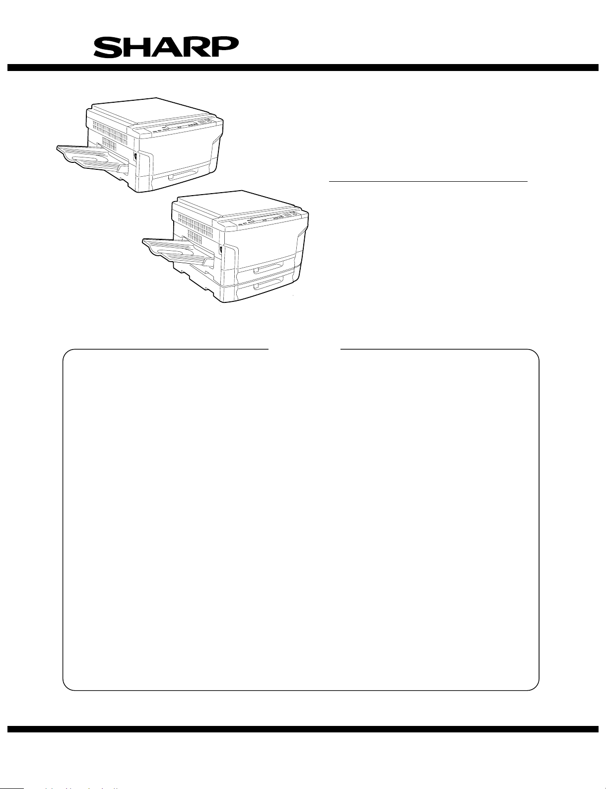
MODEL SF-2116
MODEL SF-2118
SF-2116
SF-2118
CONTENTS
[ 1 ] PRODUCT OUTLINE . . . . . . . . . . . . . . . . . . . . . . . . . . . . . . . . . . . . . . . . . . . . 1 – 1
[ 2 ] PRODUCT SPECIFICATIONS . . . . . . . . . . . . . . . . . . . . . . . . . . . . . . . . . . . . . 2 – 1
[ 3 ] PRODUCT VIEWS . . . . . . . . . . . . . . . . . . . . . . . . . . . . . . . . . . . . . . . . . . . . . . 3 – 1
[ 4 ] UNPACKING AND INSTALLATION . . . . . . . . . . . . . . . . . . . . . . . . . . . . . . . . . 4 – 1
[ 5 ] DESCRIPTION ON EACH SECTION . . . . . . . . . . . . . . . . . . . . . . . . . . . . . . . . 5 – 1
Option • Paper tray (SF-UB15)
• Multi paper feed unit (SF-MF15)
• Two-step paper feed unit
(SF-CM15)
• Personal counter (SF-71A/71B)
• 10-bin sorter (SF-S17) @
• Reverse document feeder
(SF-A15) @
@For the options, refer to their service
manuals.
[ 6 ] DISASSEMBLY AND ASSEMBLY . . . . . . . . . . . . . . . . . . . . . . . . . . . . . . . . . . 6 – 1
[ 7 ] ADJUSTMENT . . . . . . . . . . . . . . . . . . . . . . . . . . . . . . . . . . . . . . . . . . . . . . . . . 7 – 1
[ 8 ] SIMULATIONS . . . . . . . . . . . . . . . . . . . . . . . . . . . . . . . . . . . . . . . . . . . . . . . . . 8 – 1
[ 9 ] SELF DIAGNOSTICS . . . . . . . . . . . . . . . . . . . . . . . . . . . . . . . . . . . . . . . . . . . . 9 – 1
[10] MEMORY TROUBLES, FLOWCHART FOR REPLACEMENT OF
MAIN CONTROL PWB . . . . . . . . . . . . . . . . . . . . . . . . . . . . . . . . . . . . . . . . . . 10 – 1
[11] MAINTENANCE . . . . . . . . . . . . . . . . . . . . . . . . . . . . . . . . . . . . . . . . . . . . . . . 11 – 1
[12] ELECTRICAL SECTION . . . . . . . . . . . . . . . . . . . . . . . . . . . . . . . . . . . . . . . . . 12 – 1
Parts marked with "!" is important for maintaining the safety of the set. Be sure to replace these parts with specified
ones for maintaining the safety and performance of the set.
This document has been published to be used
SHARP CORPORATION
for after sales service only.
The contents are subject to change without notice.
Page 2
[1] PRODUCT OUTLINE
1. Product features
(1) Compact body
• Compact body size
The body width of 600mm is the smallest in the class.
• The employment of the front loading tray and the folding-type multi
manual paper feed cassette realizes the small occupying area.
(Option)
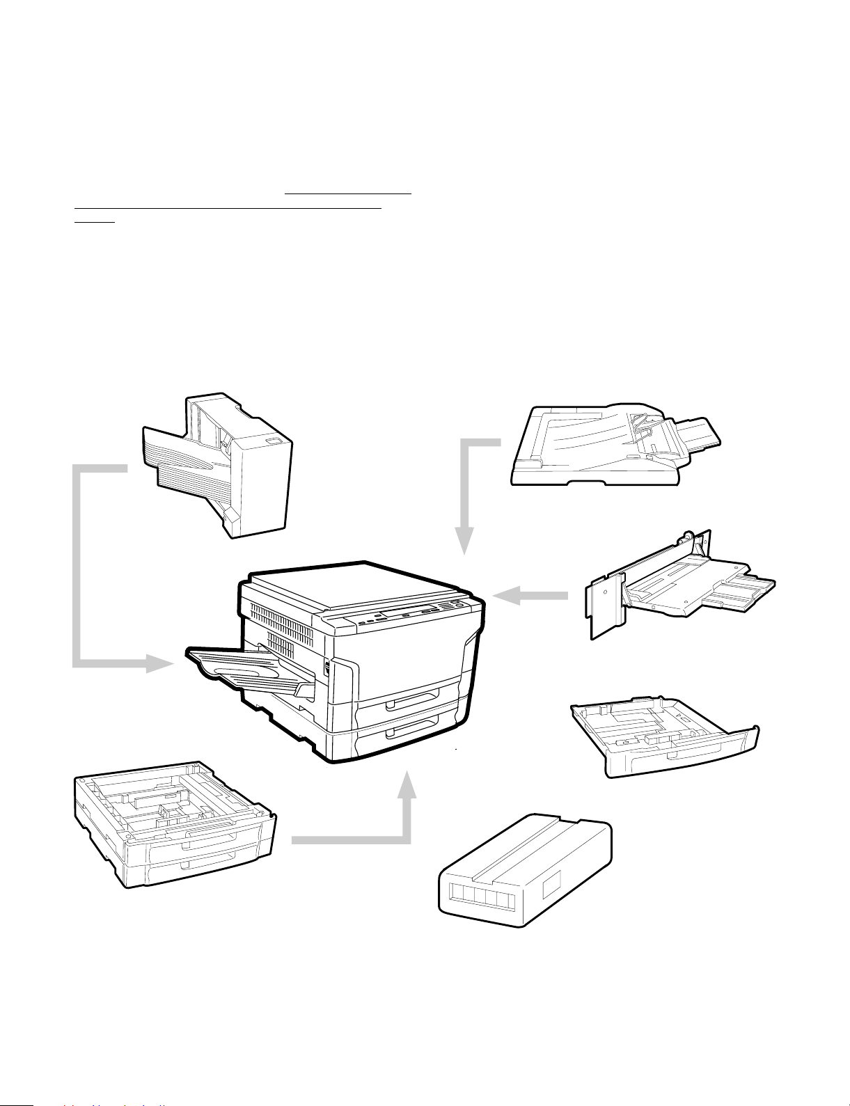
2. System configuration (options)
(2) Clean copy gentle to the environment
• Silent design of 46dB,
• Low level of ozone, use of recyclable materials
• The energy-saving mode reduces the power consumption.
(3) High capacity of copying
• Warm-up time is less than 35 sec. The first copy of 5.3 sec is the
fastest in the class.
(4) Fully expandable system. (Refer to "2. System configuration.")
Reverse document feeder SF-A15
10-bin sorter SF-S 17
Two-step paper feed unit SF-CM15
(Option for SF-211 8 onl y)
99
Multi paper feed unit SF-MF-15
Tray (reserve) SF-UB15
9
9
9
0
1 – 1
Personal counter
Page 3
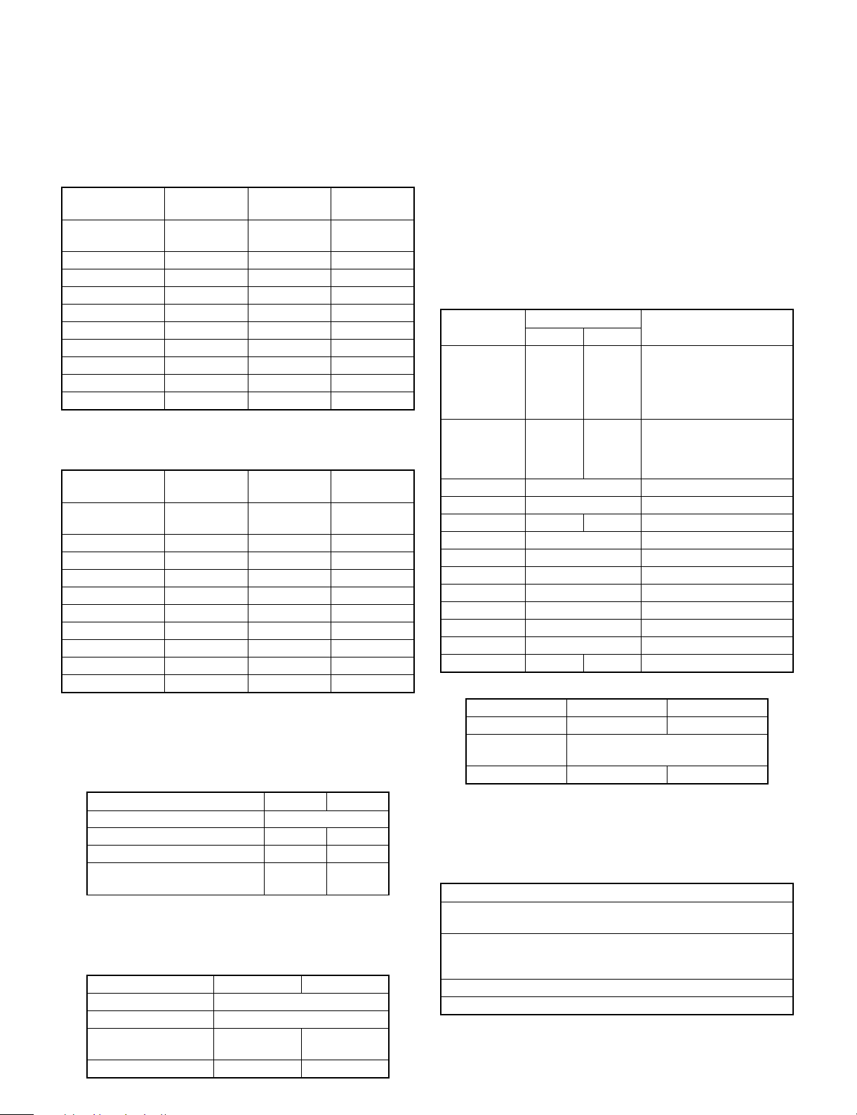
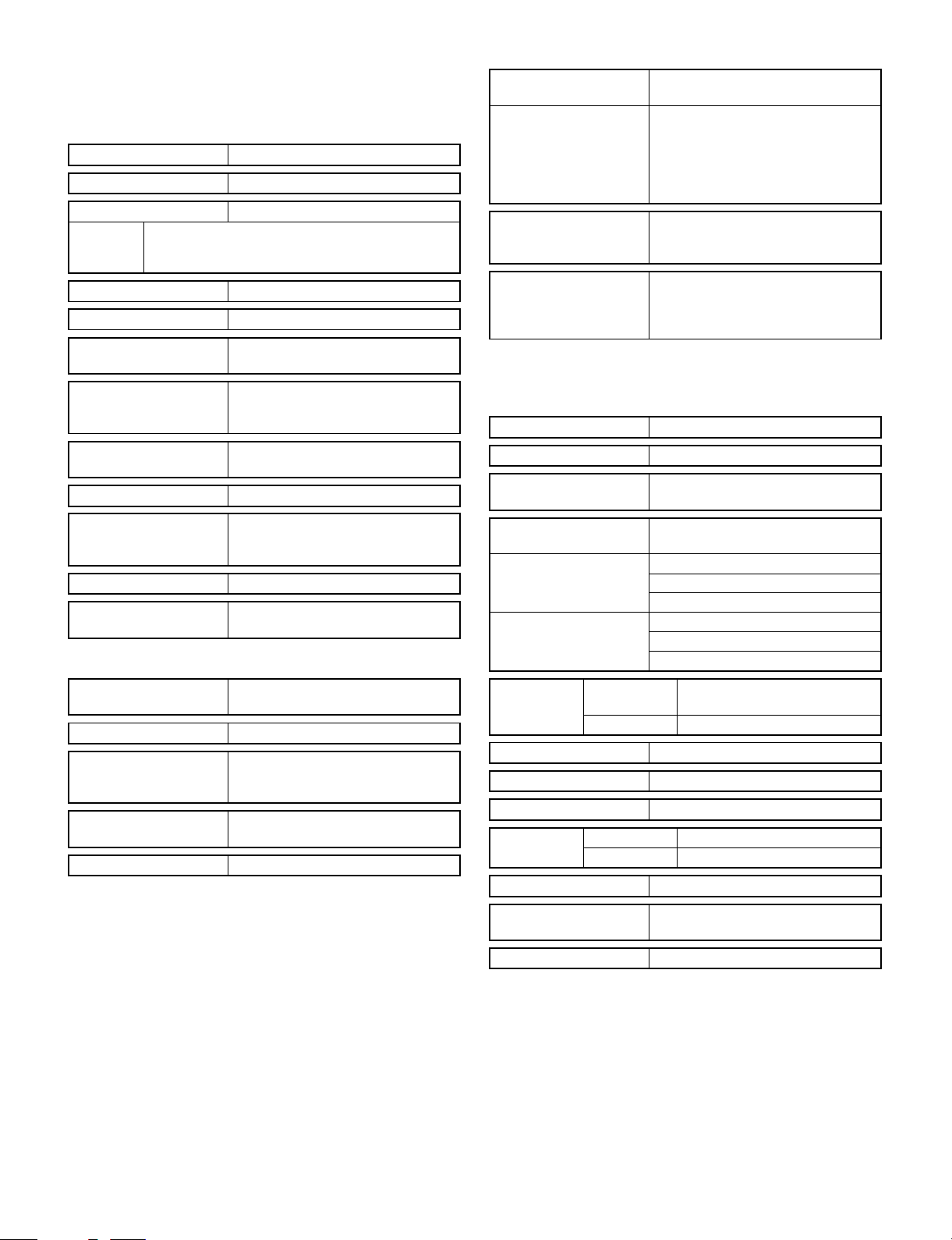
[2] PRODUCT SPECIFICATIONS
1. Basic specifications
(1) Type: Table top
(2) Copy speed:
<SF-2116>
Normal
A3 9 sheets/min 9 sheets/min
B4 11 sheets/min 11 sheets/min 11 sheets/min
A4 (Portrait) 16 sheets/min 13 sheets/min 13 sheets/min
A4 (Landscape) 13 sheets/min 13 sheets/min 13 sheets/min
B5 (Portrait) 16 sheets/min 13 sheets/min 13 sheets/min
B5 (Landscape) 13 sheets/min 13 sheets/min 13 sheets/min
W letter 9 sheets/min 9 sheets/min 9 sheets/min
Legal 11 sheets/min 11 sheets/min 11 sheets/min
Letter (Portrait) 16 sheets/min 13 sheets/min 13 sheets/min
Letter (Landscape) 13 sheets/min 13 sheets/min 13 sheets/min
(Note) The copy speeds for enlargement and reduction are the lowest
ones.
<SF-2118>
Normal
A3 10 sheets/min 10 sheets/min
B4 12 sheets/min 12 sheets/min 12 sheets/min
A4 (Portrait) 18 sheets/min 14 sheets/min 14 sheets/min
A4 (Landscape) 14 sheets/min 14 sheets/min 14 sheets/min
B5 (Portrait) 18 sheets/min 14 sheets/min 14 sheets/min
B5 (Landscape) 14 sheets/min 14 sheets/min 14 sheets/min
W letter 10 sheets/min 10 sheets/min 10 sheets/min
Legal 12 sheets/min 12 sheets/min 12 sheets/min
Letter (Portrait) 18 sheets/min 14 sheets/min 14 sheets/min
Letter (Landscape) 14 sheets/min 14 sheets/min 14 sheets/min
(Note) The copy speeds for enlargement and reduction are the lowest
ones.
(3) Warm up time: 35 sec or less
(4) First copy time: 5.3 sec (Paper feed port: Upper tray)
First copy time from each paper feed port
Paper feed port SF-2116 SF-2118
Body tray upper stage 5.3 sec
Body tray lower stage NO 5.8 sec
Option paper feed unit first step NO 6.1 sec
Option paper feed unit second
step
(5) Jam recovery time: 8 sec (Conditions: After leaving the door
open for 60 sec, the standard conditions)
(6) Multi copy Max. 99 sheets
(7) Original
Max. original size A3/W letter
Reference original size Left side/Center
Original sensing
Sensing size — A3 ∼ B5R
Enlargement
(Magnification)
(200%)
Enlargement
(Magnification)
(200%)
NO 6.4 sec
SF-2116 SF-2118
NO
Reduction
(Magnification)
9 sheets/min
(50%)
Reduction
(Magnification)
10 sheets/min
(50%)
YES
(Japan only)
(8) Copy magnification ratio
Fixed magnification: 200, 141, 122, 115, 100, 86, 81, 70, 50% (9
steps)
Zoom range: 50% ∼ 200% (151 steps by the increment of 1%)
(9) Exposure
Exposure mode: Auto/Manual/Photo
No. of manual steps: 9 steps
(10) Void width
Void area: Lead edge/rear edge: 3mm or less
Image loss Normal: 4mm or less
(11) Paper exit/finishing
Paper exit tray capacity: 250 sheets
Finishing: option 10-bin sorter
(12) Additional functions
Function
SF-2116 SF-228
Auto Paper
Selection
× F
Auto
Magnification
ratio Selection
Shift ×
1-set 2-copy F Enlargement is impossible.
Edge erase × F
Trimming ×
Masking ×
Centering ×
Move image ×
Covers/inserts ×
Overlay ×
Job memory ×
Monochrome × F (Red, Blue)
(13) External dimensions
W x D x H mm 600 x 585 x 375 600 x 585 x 460
Occupying area
(W x D)
Weight 43.5Kg 49.5Kg
(14) Power source
Voltage: 100V 50/60Hz, 110V 50/60Hz, 120V 60Hz, 127V 60Hz,
Frequency: 50/60Hz common
(15) Power consumption
Max. power consumption 1.5kw
Stand-by power
consumption
Average power
consumption during
operation
Preheating 70W
Auto power shut off 15W
2 – 1
× F
SF-2116 SF-2118
220 ∼ 230V 50/60Hz, 240V 50Hz
18W (Heater lamp OFF)
1kW (Heater lamp ON)
1320W
For the SF-2118 (outside
Japan version), original
sensing is possible when
the ADF (option) is
installed.
Inhibited in mixed size
paper feed. For outside
Japan version, the original
size is entered.
850 x 585
Remark
Page 4
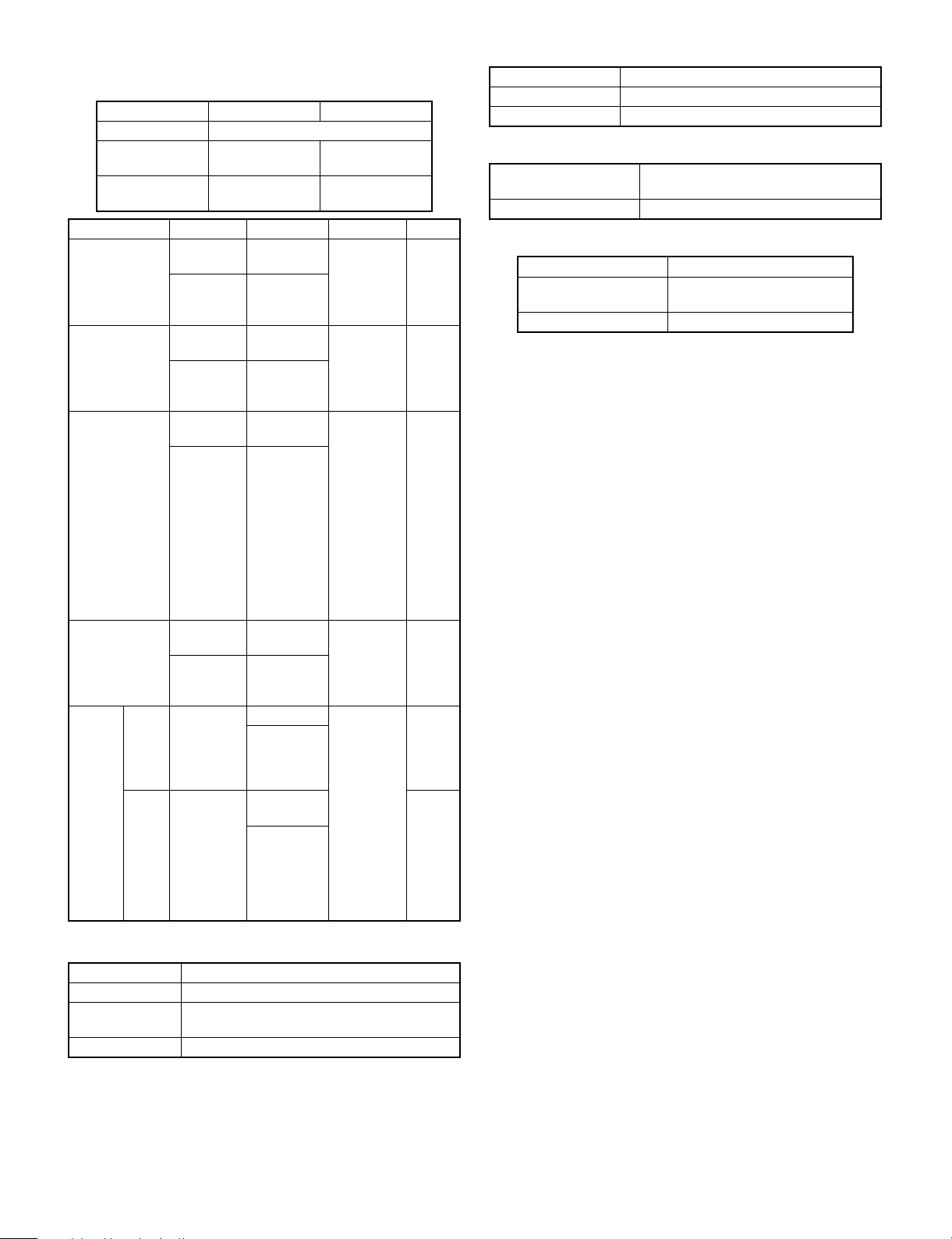
2. Description of each section
(1) Paper feed section
SF-2116 SF-2118
Copying size A3 ∼ A6/W letter ∼ Invoice
Paper feed
system
Paper feed
capacity
Cassette Paper size Paper weight Paper kind Remark
Body tray
upper stage
Body tray lower
stage
Manual feed
Two-step paper
feed unit
(Option)
Multi
Multi
manual
paper
feed
(Option)
Single
1 tray + Single
manual feed
AB series:
A3 ∼ A5
Inch series:
W letter ∼
Invoice
AB series:
A3 ∼ A5
Inch series:
W letter ∼
Invoice
AB series:
A3 ∼ A6R
Inch series:
W letter ∼
Invoice
AB series:
A3 ∼ A5
Inch series:
W letter ∼
Invoice
AB series:
A3 ∼ A6R
Inch series:
W letter ∼
Invoice
AB series:
A3 ∼ A6R
Inch series:
W letter ∼
Invoice
2 trays ∼ Single
manual feed
250 sheets 250 x 2 sheets
56 ∼ 80g/m
2
Standard
paper,
2
recycled
paper
Standard
15 ∼ 20 lbs
56 ∼ 80g/m
paper,
15 ∼ 20 lbs
52 ∼
128g/m
recycled
paper
Standard
2
paper,
specified
paper,
special
paper,
OHP film,
14 ∼ 34 lbs
Second
original
paper,
postcards
(without
folding)
56 ∼ 80g/m
2
Standard
paper,
15 ∼ 20 lbs
recycled
paper
56 ∼ 80g/m2Standard
paper,
15 ∼ 20 lbs
specified
paper,
special
52 ∼
128g/m
paper,
OHP film,
2
Second
original
paper,
14 ∼ 34 lbs
postcards
(without
folding)
SF-2118
only
(3) Process
Charging system (–) DC saw teeth electrode system
Transfer system (–) tungsten system
Separation system (AC) separation tungsten system
(4) Developing section
Developing system Dry, two-component magnetic brush
development (developer replacement)
Developing bias voltage DC–200V ±5V
(5) Fusing section
Fusing system Heat roller system
Upper heat roller
surface temperature
190 degrees
Heater lamp Halogen lamp 1000W × 1
(2) Optical section
Light source Halogen lamp
Exposure system Slit exposure by moving the light source
Zooming system By changing the lens positions and the scan
speed.
Lens Fixed focus lens
2 – 2
Page 5

3. Supply parts
U.S.A., Canada
Name Content Life Product name
1 Photoconductor kit Photoconductor drum x 1
Cleaner blade x 1
Drum separation pawl x 2
2 Black developer Black Black developer (530g) x 10 50K x 10 SF-216MD1
3 Color developer Red Color developer (550g) x 10 10K x 10 SF-780MD2
Blue SF-780MD3
4 Black toner Black Black toner cartridge (210g) x 10 5K x 10 SF-216MT1
5 Color toner Red Color toner cartridge (210g) x 10 5K x 10 SF-216MT2
Blue SF-216MT3
6 Color developing unit
kit
7 Upper heat roller kit Upper heat roller x 1
8 Lower heat roller kit Lower heat roller x 1
Red Developing unit x 1
Blue SF-216NK3
Color developer (550g) x 1
Color toner cartridge (210g) x 1
Storage case x 1
Upper fusing separation pawl x 4
Fusing bearing (F) x 1
Lower fusing separation pawl x 2
Europe/U.K.
Name Content Life Product name
1 Photoconductor kit Photoconductor drum x 1
Cleaner blade x 1
Drum separation pawl x 2
2 Black developer Black Black developer (530g) x 10 50K x 10 SF-216LD1
3 Color developer Red Color developer (550g) x 1 10K SF-780DV2
Blue SF-780DV3
4 Black toner Black Black toner cartridge (210g) x 10 5K x 10 SF-216LT1
5 Color toner Red Color toner cartridge (210g) x 1 5K SF-216T2
Blue SF-216T3
6 Color developing unit
kit
7 Upper heat roller kit Upper heat roller x 1
8 Lower heat roller kit Lower heat roller x 1
Red Developing unit x 1
Blue SF-216K3
Color developer (550g) x 1
Color toner cartridge (210g) x 1
Storage case x 1
Upper fusing separation pawl x 4
Fusing bearing (F) x 1
Lower fusing separation pawl x 2
50K SF-216DR
SF-216NK2
100K SF-216UH
50K SF-216LH
50K SF-216DM
SF-216K2
100K SF-216UH
50K SF-216LH
Australia/New Zealand
Name Content Life Product name
1 Photoconductor kit Photoconductor drum x 1
Cleaner blade x 1
Drum separation pawl x 2
2 Black developer Black Black developer (530g) x 10 50K x 10 SF-216LD1
3 Color developer Red Color developer (550g) x 10 10K x 10 SF-780LD2
Blue SF-780LD3
4 Black toner Black Black toner cartridge (210g) x 10 5K x 10 SF-216LT1
5 Color toner Red Color toner cartridge (210g) x 10 5K x 10 SF-216LT2
Blue SF-216LT3
6 Color developing unit
kit
7 Upper heat roller kit Upper heat roller x 1
8 Lower heat roller kit Lower heat roller x 1
Red Developing unit x 1
Blue SF-216K3
Color developer (550g) x 1
Color toner cartridge (210g) x 1
Storage case x 1
Upper fusing separation pawl x 4
Fusing bearing (F) x 1
Lower fusing separation pawl x 2
2 – 3
50K SF-216DM
SF-216K2
100K SF-216UH
50K SF-216LH
Page 6

Middle and South America/Asia
Name Content Life Product name
1 Photoconductor kit Photoconductor drum x 1
2 Black developer Black Black developer (530g) x 10 50K x 10 SF-216CD1
3 Color developer Red Color developer (550g) x 10 10K x 10 SF-780LD2
Blue SF-780LD3
4 Black toner Black Black toner cartridge (210g) x 10 5K x 10 SF-216CT1
5 Color toner Red Color toner cartridge (210g) x 10 5K x 10 SF-216CT2
Blue SF-216CT3
6 Color developing unit
kit
7 Upper heat roller kit Upper heat roller x 1
8 Lower heat roller kit Lower heat roller x 1
Red Developing unit x 1
Blue SF-216SK3
Cleaner blade x 1
Drum separation pawl x 2
Color developer (550g) x 1
Color toner cartridge (210g) x 1
Storage case x 1
Upper fusing separation pawl x 4
Fusing bearing (F) x 1
Lower fusing separation pawl x 2
50K SF-216DR
SF-216SK2
100K SF-216UH
50K SF-216LH
Middle East/Africa (excluding Russia)
Name Content Life Product name
1 Photoconductor kit Photoconductor drum x 1
Cleaner bladex 1
Drum separation pawl x 2
2 Black developer Black Black developer x 10 50K x 10 A3SF216LD1
3 Black toner Black Black toner bottle (250g) x 10 6K x 10 A3SF116LT
4 Upper heat roller kit Upper heat roller x 1
Upper fusing separation pawl x 4
Fusing bearing (F) x 1
5 Lower heat roller kit Lower heat roller x 1
Lower fusing separation pawl x 2
50K A3SF216DM
100K A3SF216UH
50K A3SF216LH
Asia (Excluding Taiwan(AURORA)/Hong Kong (SRH))
Name Content Life Product name
1 Photoconductor kit Photoconductor drum x 1
2 Black developer Black Black developer x 10 50K x 10 A3SF216CD1
3 Black toner Black Black toner bottle (250g) x 10 6K x 10 A3SF116CT
4 Upper heat roller kit Upper heat roller x 1
Lower heat roller kit Lower heat roller x 1
5
Cleaner bladex 1
Drum separation pawl x 2
Upper fusing separation pawl x 4
Fusing bearing (F) x 1
Lower fusing separation pawl x 2
50K A3SF216DR
100K A3SF216UH
50K
A3SF216LH
2 – 4
Page 7
4. Optional specifications
(1) Automatic document feeder (ADF)
<SF-A15>
Original set direction Face down
Original set position Center reference
Original transport system Belt (half size) system
Remark For an original of A4 or greater, it is once transported
to the paper exit section and switched back to set the
next original.
Original feed sequence Top taking (Face up exit)
Original size A3 ∼ A5/11" x 17" ∼ 8 1/2" x 5 1/2"
Original change speed
(S → S)
Original weight 35 ∼ 128g/m
Original set quantity 50 sheets, 80 ~ 128 g/cm2,
Original stop system Stopper system
Dimensions 586 (W) x 525 (D) x 99 (H) (mm)
Weight About 11kg
Power source AC100V ∼ 200V supplied from the
Functions
Original sensing on the
tray
Tray form Slide system
Sensing size Inch series: 11" x 17", 8 1/2" x 14", 8
Original mixture Allowed (However, no linkage with the
Original reverse NO
16 sheets/min (SF-2116), 18
sheets/min (SF-2118)
2
Thin paper mode (35 ∼ 50g/m2)
Standard mode (50 ∼ 128g/m2)
thickness max. 5 mm
(Width: when the tray is installed.
Height: Excluding the auxiliary guide.)
copier’s power section.
YES (Scanning read for uncertain size
originals.)
1/2" x 11", 8 1/2" x 11"R, 8 1/2" x 5 1/2"
AB series: A3, B4, A4, A4R, A5
AMS)
Display section
1 Original feed display
section
2 Original remaining
display
SDF mode Selection between the SDF mode and
Thin paper mode Selection between the thin paper
ADF shows the operation valid state.
Lighted when an original is set.
When the original transport cover is
used as the original cover, the LED
lights up on completion of the final
exposure.
When the transport cover is opened,
the LED goes off.
the ADF mode is possible. (Selectable
with the user program.)
mode and the standard mode is
possible. (Selectable with the user
program.)
(2) 10-bin sorter
<Model name: SF-S17>
Type Copier installation type/Hanging type
Distribution system Bin shift by lead screw
No. of bins 10 bins (The top bin is used also for
non-sort.)
Capacity 30 sheets/bin (L4/letter size), 100
Sorting 30 sheets (A4/letter)
Grouping 20 sheets (A4/letter)
Paper size (Non-sort) A3 ∼ A6 (Postcard)R/11" x 17" ∼
(Sort/group) A3 ∼ A5/11" x 17" ∼ 8 1/2" x 11"
Process capacity 16/18 sheets/min
Paper transport Center reference
Paper reception Face up
Paper weight (Non-sort) 52 ∼ 128g/m2 (14 ∼ 34lbs)
(Sort/group) 56 ∼ 80g/m2 (15 ∼ 21lbs)
Power source Supplied from the copier.
sheets for the top bin only.
15 sheets (B4/legal)
15 sheets (A3/W letter)
15 sheets (B4/legal)
15 sheets (A3/W letter)
8 1/2" x 5 1/2"
Dimensions 335 (W) x 493 (D) x 298 (H)
Weight 7kg
2 – 5
(Width: Including the tray.)
Page 8
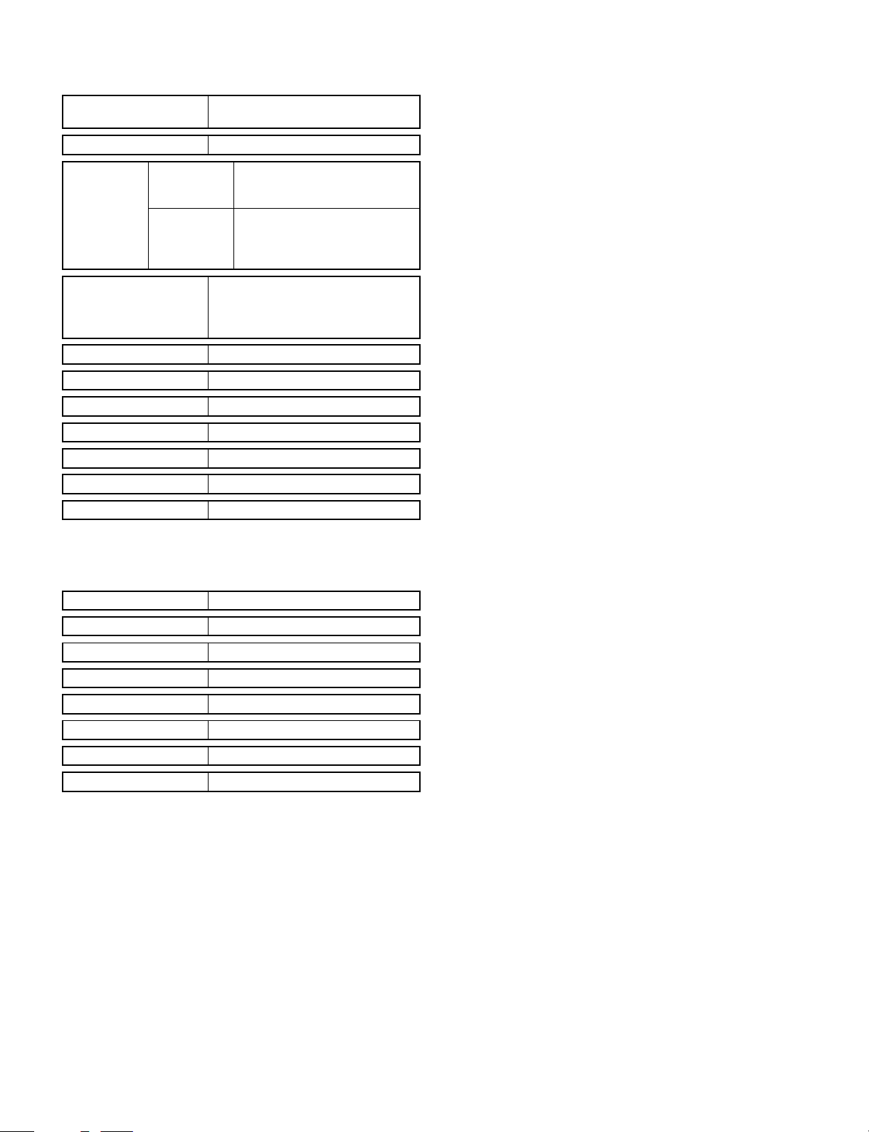
(3) Multi manual feed unit
<Model name: SF-MF15>
Paper size A3 ∼ A6 (Postcard) R
11" x 17" ∼ 8 1/2" x 5 1/2"
Paper weight 52 ∼ 128g/m2, (14 ∼ 34lbs)
Paper feed
capacity
Paper kind Standard paper, specified paper,
Paper empty sense NO
Manual feed size sense NO
Paper feed tray Folding type
Paper set Same size only
Power source Supplied from the copier.
Dimensions (W x D x H) 350 (W) x 493 (D) x 185mm (H)
Weight About 2kg
MUlti paper
feed
Single paper
feed
56 ∼ 80g/m2 (15 ∼ 21lbs) (50
sheets)
Postcard (20 sheets)
52 ∼ 128g/m2, (14 ∼ 34lbs) and
special paper (For paper of
105g/m2 (28lbs) or heavier, A4
size or lower.)
special paper, OHP film, Second
original paper, postcards (without
folding)
(4) Two-step paper feed unit (SF-2118 only)
<Model name: SF-CM15>
Paper size A3 ∼ A5
Paper feed capacity 250 sheets x 2 steps
Paper weight 56 ∼ 80g/m2 (15 ∼ 21 lbs)
Paper kind Standard paper, recycled paper
Size selection Tray replacement/user handling
Power source Supplied from the copier.
Dimensions (W x D x H) 570 (W) x 570 (D) x 188mm (H)
Weight About 14kg
2 – 6
Page 9
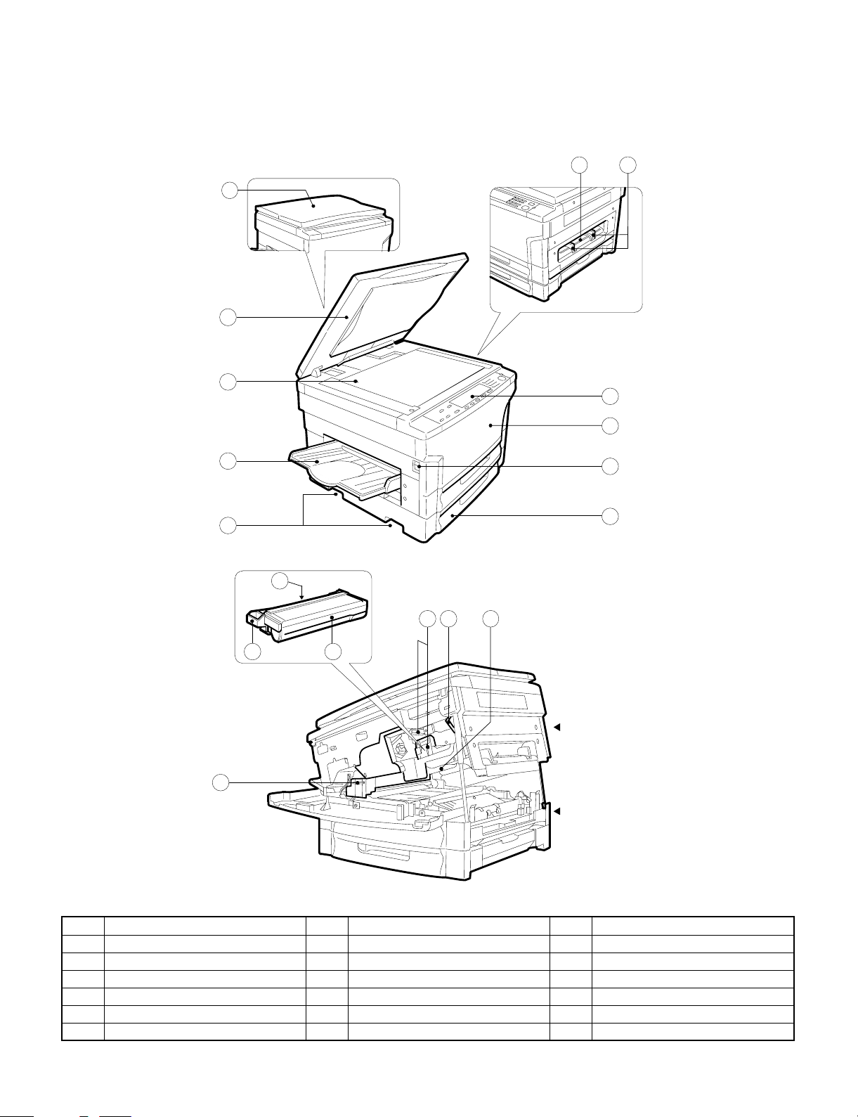
[3] PRODUCT VIEWS
1. External view and internal structure
1
2
3
67
8
9
4
5
12 14
17
10
11
13
15 16 18
Upper unit
Lower unit
No. Name No. Name No. Name
1 Original cover 2 Original table 3 Paper exit tray
4 Grip 5 Manual feed unit 6 Manual feed original guide
7 Operation panel 8 Front cover 9 Power switch
F Paper tray G Developing unit grip H Developing unit strap
I Toner hopper J Developing unit lock lever K Release lever
L Fusing unit M Drum
3 – 1
Page 10
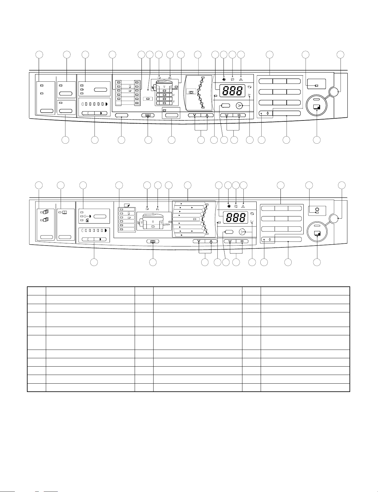
2. Operation panel
SF-2118
1
SORT ER
SORT
GROUP
SF-2116
1
2
DUAL PAGE
COPY
EDGE
ERASE
3 4 5 6 7 8 9 10 11121314 15 16 17
EXPOSURE
AUT O
MANUAL
PHOTO
0 1 2 3 4
. . . .
ORIGI NA L
SIZE
ORIGINAL S IZE
ENTER
EXTRA
PAPER
SIZE
A3
A4
A4
AUTO PAPER
A5
SELEC T
B4
TRAY SELECT
AUTO I MAG E
PRESET
RAT IO
100%
115%
86%
122%
81%
141%
70%
200%
50%
0 1 2
ZOOM
%
3
6 4 8 5 9
//
18 19 2 0 21 22 23 24 25 26 27 28 2 9 30
2
...
0,2,3,
...
0,2,3,
...
1,2,
...
0,1,
357
AUTO
0
1 2 3 4
. . . .
A3
A4
A4
A5
B4
EXTRA
8
910 11121314 15 16 17
A5
A4
A4
B4
A3
B4
A4
A3
A3
A3 A5
B4
A3
100%
B4
A4
A5 A3
200%
A4
141%
122%
115%
ZOOM
86%
81%
70%
A4
A5
%
50%
012
3
64859
// C
POWER SAVE
CA
C
CA
19 21 23 24 26 27 28 29 30
25
No. Name No. Name No. Name
1 Sorter key and indicators 2 Dual page copy key and indicators 3 Auto/Manual/Photo key and indicators
4 Original size indicators 5 Paper size indicators 6 Auto paper select indicators
7 Paper required indicator 8 Misfeed indicator 9 Paper feed location/misfeed location
indicators
F Preset ratio indicators G Copy quantity display H Maintenance required indicator
I Developer replacement required
J Toner required indicator K 10-Key pad
indicator
L Power save indicator M Clear all key N Edge erase
O Light and dark keys and indicator P Original size enter key Q Tray select key
R Auto image key and indicator S Copy ratio keys T Zoom indicator
U Copy ratio display key V Zoom keys W Interrupt key and indicator
X Zero/readout key Y Clear key Z Print button and ready indicator
3 – 2
Page 11
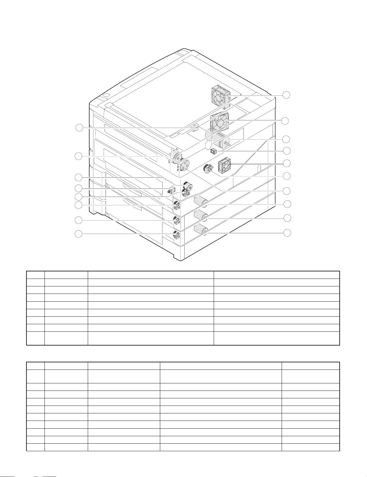
3. Clutches, solenoids, and motors
Clutches and solenoids
12
9
11
10
14
3
8
4
5
6
7
No. Signal name Name Functions, operations
1 PSPS Paper separation solenoid Paper separation solenoid drive
2 RRC Resist roller clutch For resist roller rotation
3 TRC Transport roller clutch For transport roller rotation
4 CPFC1 Tray paper feed clutch For paper feed roller rotation
5 CPFC2 Tray paper feed clutch (SF-2118) For paper feed roller rotation
6 CPFC3 Option tray paper feed clutch For paper feed roller rotation
7 CPFC4 Option tray paper feed clutch For paper feed roller rotation
8 MPFS Manual paper feed solenoid
(Option 2-step paper feed unit: SF-MF15 only)
For pressing take-up roller
1
18
2
13
15
16
17
Motors
No. Signal name Name Functions, operations Type
9 VFM Ventilation fan motor Used to ventilate around the fusing section, cools
down the machine, and remove ozone.
F MM Main motor Used to drive the body. DC brush
G CFM Optical system cooling fan Used to cool and ventilate the optical system. DC brushless
H LM Lens motor Used to move the optical lens. DC stepping
I TM Toner motor Used to stir toner. DC synchronous
J MRM Mirror motor Used to move the mirror base. DC stepping
K CS2M Paper feed motor (SF-2118) Used to drive the paper feed roller. (SF-2118) DC brush
L CS3M Option paper feed motor Used to drive the option paper feed roller. DC brush
M CS4M Option paper feed motor Used to drive the option paper feed roller. DC brush
N SMF Suction fan motor Used to ventilate the suction section. DC brushless
3 – 3
DC brushless
Page 12
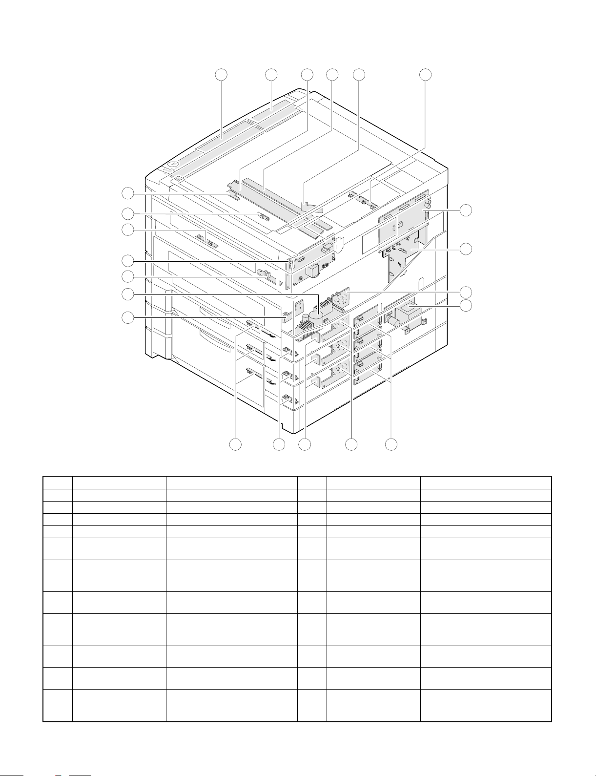
4. PWB
22
18
20
19
10
17
2
6
213 4 51
7
8
9
11
16 1214 1315
No Name Description No Name Description
1 Operation PWB A Operation input, display control 2 Operation PWB B Operation input, display control
3 Blank lamp PWB Used to control the blank lamp. 4 DL PWB Used to drive the discharge lamp.
5 Optical PWB AE sensor and lens motor interface 6 Process control PWB Used to sense the toner density.
7 Main PWB Used to control the body. 8 AC circuit PWB AC power input
9 CSD PWB Used to sense the body cassette
size.
G Paper feed power PWB Used to supply power to drive the
paper feed unit.
I CSD B PWB Used to sense the cassette size of
2nd ∼ 4th tray.
K Tray module PWB Vertical transport of 2nd ∼ 4th
cassette, JAM detection, paper
feed clutch interface
M Paper feed I/F PWB Body paper detection, paper feed
clutch interface
O PPD PWB Body PR roller JAM detection P High voltage PWB Process high voltage, developing
Q PDD PWB Body paper exit section JAM
detection, ventilation fan motor
interface
F DC circuit PWB DC power input
H Motor control PWB Used to drive and control the
paper feed motor and the
transport motor.
J Motor sensor PWB Encoder for 2nd ∼ 4th paper feed
motor
L DPPD PWB Vertical transport of 2nd ∼ 4th tray,
JAM detection and cover open
detection
N PID PWB Manual paper entry detection
bias voltage supply
R Mark sensor PWB Drum marking point detection
3 – 4
Page 13
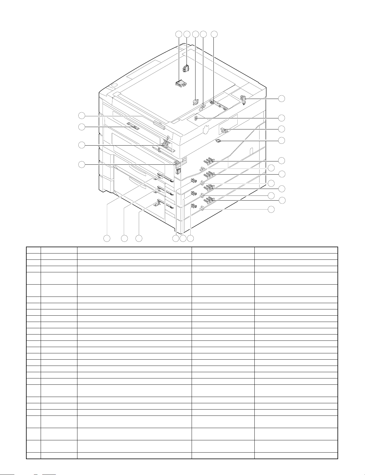
5. Sensors and switches
2 3 5 4 6
7
1
27
11
23
2224 25 26 2120
16
17
18
19
10
8
9
12
13
14
15
No. Signal name Name Type Operation, function
1 TCS Toner density control sensor Transmission sensor HIGH when toner density falls.
2 ILSW Front cabinet open/close switch Interlock switch ON when closed.
3 MSW Power switch Seesaw switch
4 TH Fusing heater thermistor Thermistor Greater resistance at low
temperature
5 TS Fusing heater thermostat Thermostat Contact open at abnormally high
temperature
6 POD Paper exit paper sensor Transmission photo sensor LOW when paper is present.
7 MHPS Mirror home position sensor Transmission photo sensor HIGH when paper is sensed.
8 MMRE Main motor encoder Transmission photo sensor Rotation pulse output
9 TFD Waste toner full switch Lead switch HIGH when sensed.
F LHPS Lens home position sensor Transmission photo sensor LOW when reduction.
G PPD Paper transport sensor Transmission photo sensor LOW when paper is present.
H 1 CSD0 ∼ 2 Body upper tray paper size detection Tact switch Shorted when the switch is turned on.
I 2 CSD0 ∼ 2 Body lower tray paper size detection (SF-2118) Tact switch Shorted when the switch is turned on.
J 3 CSD0 ∼ 2 Option upper tray paper size detection Tact switch Shorted when the switch is turned on.
K 4 CSD0 ∼ 2 Option lower tray paper size detection Tact switch Shorted when the switch is turned on.
L PED1 Body upper tray paper presence detection Transmission photo sensor HIGH when paper is present.
M PED2 Body lower tray paper presence detection (SF-2118) Transmission photo sensor HIGH when paper is present.
N PED3 Option upper tray paper presence detection Transmission photo sensor HIGH when paper is present.
O PED4 Option lower tray paper presence detection Transmission photo sensor HIGH when paper is present.
P Motor sensor 2 Body lower stage paper feed motor encoder sensor
Transmission photo sensor Rotation pulse output
(SF-2118)
Q Motor sensor 3 Option upper paper feed motor encoder sensor Transmission photo sensor Rotation pulse output
R Motor sensor 4 Option lower paper feed motor encoder sensor Transmission photo sensor Rotation pulse output
S DPPD1 Body upper tray paper transport sensor Transmission photo sensor LOW when paper is present.
T DPPD2 Body lower tray paper transport sensor (SF-2118) Transmission photo sensor LOW when the side door is open
and paper is present.
U DPPD3 Option upper tray paper transport sensor Transmission photo sensor LOW when the option door is open
and paper is present.
V DPPD4 Option lower tray paper transport sensor Transmission photo sensor LOW when the option door is open
and paper is present.
W PID Single manual feed paper entry sensor Transmission photo sensor HIGH when paper is present.
3 – 5
Page 14
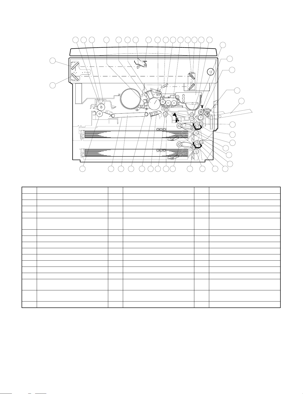
6. Rollers, mirrors, etc.
30 29 28
20 19 18 3 4 17 7 34 16
6
5 8 14
15
2
12
13
1
11
9
32
33
35
36
37
39
31 27 26 25 24 23 22 21 43 42 41
38 40
No. Name No. Name No. Name
1 No. 3 mirror 2 No. 2 mirror 3 No. 1 mirror
4 Copy lamp 5 No. 4 mirror 6 No. 5 mirror
7 No. 6 mirror 8 Developing unit toner box 9 Manual tray
F — G Take-up roller (SF-MF15 only) H Paper feed roller (SF-MF15 only)
I Reverse roller (SF-MF15 only) J PS front roller follower roll
(SF-MF15 only)
L Developing unit M Blank lamp N Main charger unit
O Photoconductor drum P Cleaner unit Q Resist roller follower roll
R Resist roller S Transfer charger T Separation charger
U Drum separation pawl V Suction unit W Suction belt
X Fusing thermistor Y Heater lamp Z Upper heat roller
[ Lower heat roller \ Transport roller (upper) follower roller ] Transport roller (upper)
^ Developing magnet roller _ Tray paper feed roller ‘ Tray paper feed reverse roller
a Tray paper feed take-up roller b PE actuator c Transport roller (lower) (SF-2118)
d Transport roller (lower) follower roller
(SF-2118)
g Tray paper feed take-up roller
(SF-2118)
@ Since \, ], _ ~ g are the same as in the SF-C M 15 (option), they are omitted.
@ The above figure shows the machine with the SF-MF15 installed.
e Tray paper feed reverse roller
(SF-2118)
K PS front roller (SF-MF15 only)
f Tray paper feed roller (SF-2118)
3 – 6
Page 15
[4] UNP ACKING AND INSTALLATION
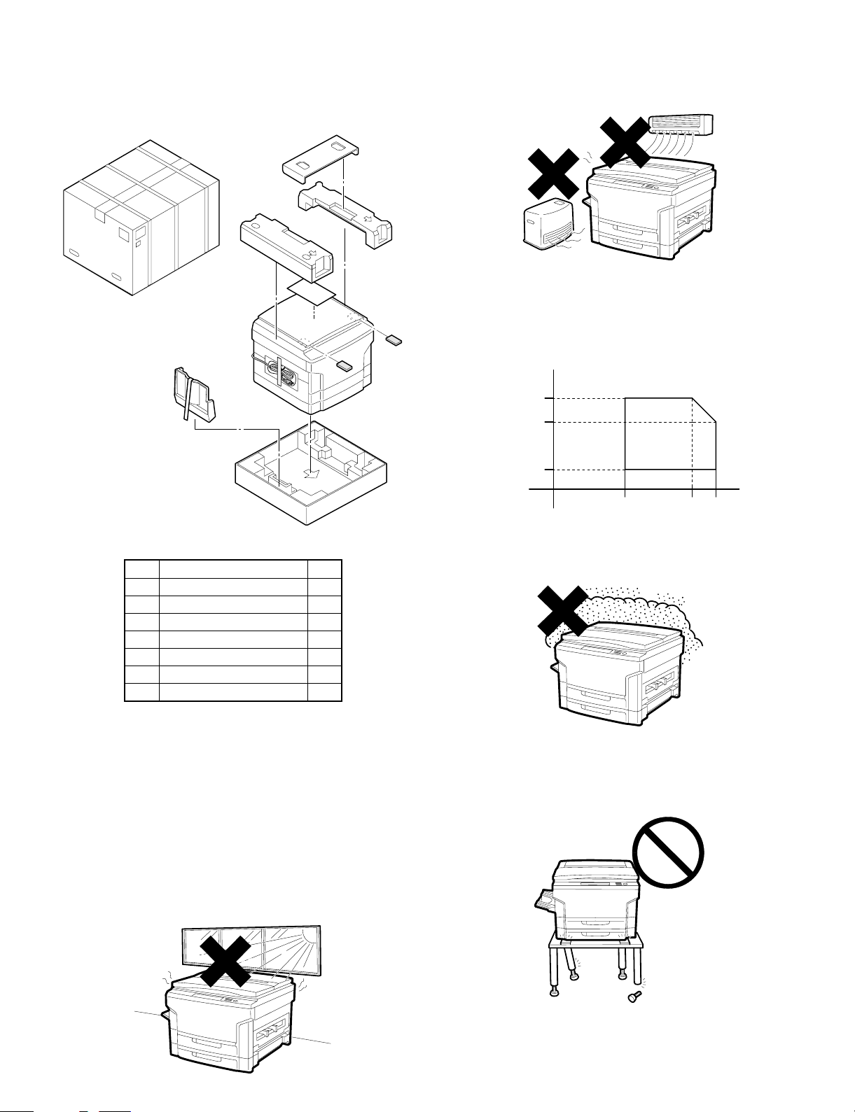
1. Unpacking
2 Avoid high temperature and high humidity, and avoid sudden
temperature change. (Avoid installation near a cooler or a heater.)
If not, paper absorbs moisture and dew forms in the machine,
causing paper jam or degraded image quality.
(Standard condition): The best condition to use the machine.
20 ∼ 25 °C, 65±5% RH
(Temperature and humidity): 15 ∼ 30 °C
HR
%
85
65
20% ∼ 85% RH
35 °C for 65%
Humidity
Packing material /accessory list
Name Q’ty
1 Paper exit tray 1
2 Instruction Manual 1
3 Maintenance card 1
4 Dust cover 1
5 Service contract 1
6 Installation manual 1
7 Magnification select label 1
2. Installat ion
Install a ti on c onditions
The surrounding conditions of the machine affect the machine performance gr eatly. U se great care for the following items:
(1) Environm en t
1 Avoid direct sunlight, and avoid installation near the window.
(Curtains or blinds must be shut completely.)
If not, the plastic parts and the original cover may be deformed.
Even if the window is of frosted glass, there is no difference.
20
15 30 35
3 Avoid dusts and vibrations.
If dusts enter the machine, malfunctions may occur.
4 Avoid installation to an unstable place.
Keep the machine in horizontal state to maintain the performances.
˚C
4 – 1
Page 16
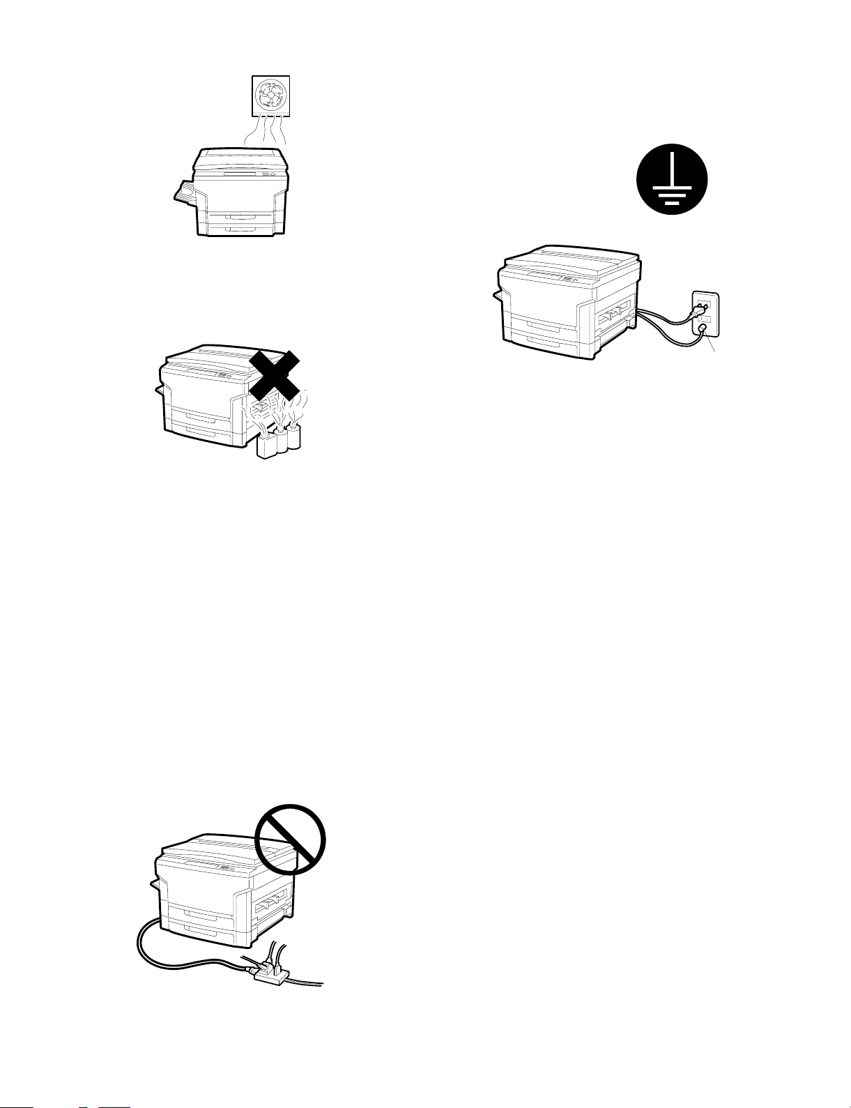
5 Avoid installation to a poorly ventilated place.
6 Avoid installation to a place where there are flammable materials
or ammonia gas, etc. If the machine is installed near a diazo
copier, the picture quality may be degraded and malfunctions may
occur.
(5) Grounding wire connection
1 Connect the grounding wire to prevent against a danger.
2 When connecting the grounding wire, connect only to the ground-
ing object (the grounding terminal of the power outlet, etc.) and
never connect to a gas pipe.
Grounding
terminal
7 Install near a power outlet.
(2) Space around the machine
Install the machine with its rear side about 10cm apart from the wall in
order to allow space for ventilation by the cooling fan.
Also allow eno ug h space around th e ma ch ine for proper operation.
(3) Installation base
Set the machine in horizontal position in the following procedure.
Be sure to use a le veling instrumen t (UKOGM0054CSZZ) to install
the machine on a flat, horizontal place.
[Note] If the machine is not in horizontal position, the toner density
control function may not work normally, resulting in degraded
picture quality.
(4) Power sou rc e
1 Use the power source of the rated capacity.
2 Avoid complicated wiring. If not, the breaker or the fuse may be
blown off to cause a fire.
4 – 2
Page 17
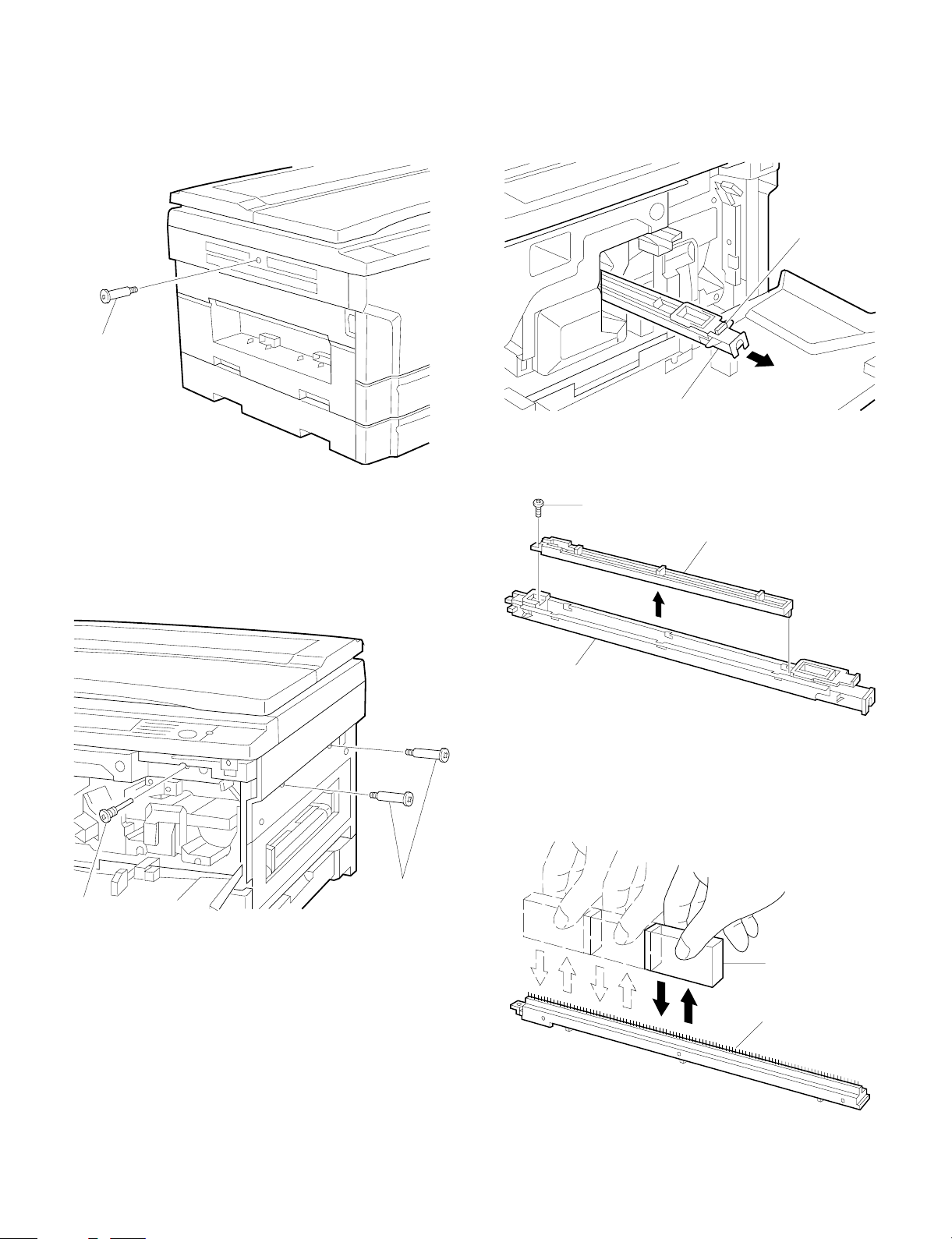
3. Optical system lock release
4. Charger cle ani ng
A. No. 2/3 mirror unit lock release
Remove the one fixing screw of the No. 2/3 mirror unit on the let side
of the copier.
Mirror unit
fixing screw
B. Lens and No. 4/5 mirror unit lock release
Remove two fixing screws of the No. 4/5 mirror unit on the right side
of the copier,
Open the fr ont cabinet and r emove one fixi ng screw of the lens on the
lower side of the operation panel.
A. Main charger unit electrode cleaning
1 Press the hook section of the main charger unit to release lock,
and pull out and remove the main charger unit from the copier.
Hook
Main charger unit
2 Remove one fixing screw of the main charger unit (on the back
side).
Fixing screw
Electrode section
Lens fixing screw
Main charger un i t
3 Press the electrode cleaner onto the tips of the electrode so that
the tips are inserted into the cleaner a few times to clean.
[Note] Do not move the cleaner back and forth with the electrode
tips inserted into it.
Mirror unit
fixing screw
Electrode
cleaner
Electrode
section
4 – 3
Page 18
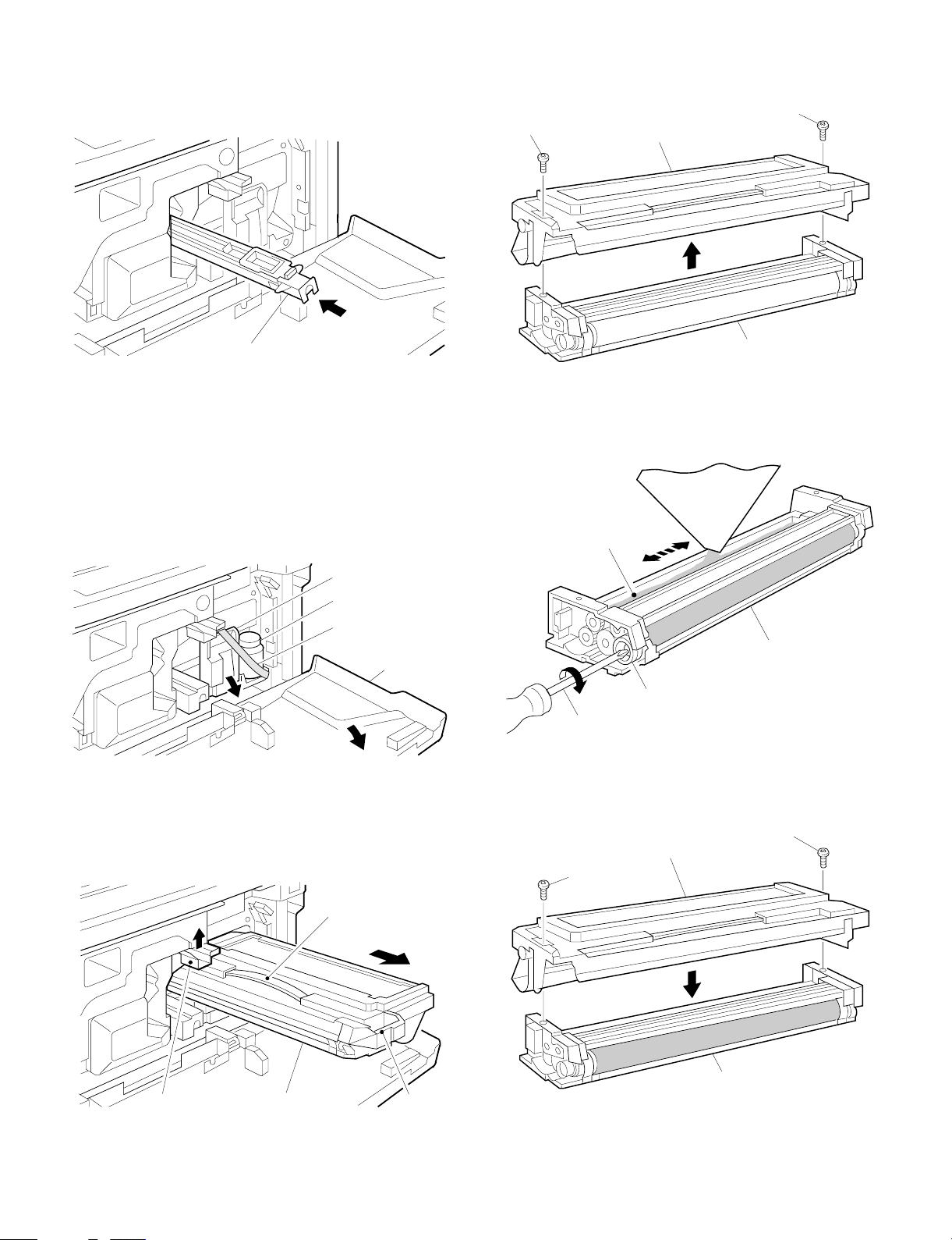
4 Return the electrode section to the original position and fix it with a
screw.
5 Insert the main charger unit along the guide groove in the copier
fully to the bottom.
3 Remove three fixing screws of the toner hopper of the developing
unit, and remove the toner hopper.
Fixing screw
Fixing screw
Toner hopper
Main charger unit
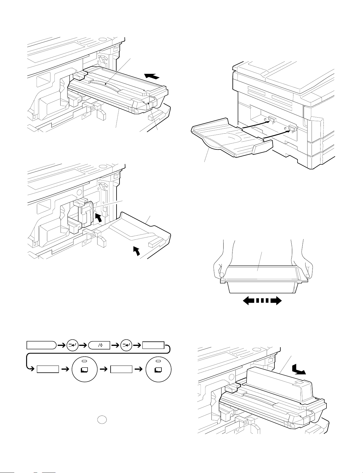
5. Developing nit set tin g
A. Developing unit setting
1 Open the front cabinet, remove the installation toner fixed to the
developing unit lever with tape, and pull the developing unit lever
toward you.
Developing unit
lever
Installation toner
Fixing tape
Front cabinet
2 Hold the grip of the developing unit, and slowly pull out the
developing unit until it stops.
Then hold the hand carry strap and press the developing lever,
and remove the developing unit.
Developing unit
4 While supplying developer from the developer supply port of the
developing unit, turn the MG gear clockwise with a screwdriver or
a scale to supply fully in the developing unit.
Developer
Developer
supply port
Developing unit
MG gear
Developing unit
5 Install the toner hopper to the developing unit and fix it with two
screws.
Fixin g scr ew
Toner hopper
Fixing screw
DV lever
Developing unit
Hand carry strap
Developing unit
Grip
4 – 4
Page 19
6 Hold the hand carry strap of the developing unit and insert it into
the copier fully to the bottom.
Hand carry strap
7. Accessor y i nst all ation
A. Copy tray installation
Install the copy tray to the paper exit section on the left side of the
copier.
Developing unit
7 Close the developing unit lever and close the front cabinet.
Grip
Developing unit lever
Front cabinet
With the above procedure, setting of the developing unit is completed.
6. Toner density sensor level adjustment
Copy tray
8. Toner supply
Toner cartridge tone r supply
1 With the sheet surface of the toner cartridge facing upward, shake
the cartridge right and left several times.
Sheet surface
Toner cartridge
Turn on the copier power switch.
A. Developing unit level adjustment
1 Execute simulation 25.
C
5
2 After 3 minutes, simulation 25 is completed.
[Note] If the simulation is terminated halfway, automatic reading is
not performed. Do not terminate it halfway.
3 Cancel simulation 25 with the CA key.
0
2
2
2 Install the toner cartridge to the toner hopper of the developing
unit, and slide it toward you until it clicks.
Be careful not to place toner one-sidedely in the toner cartridge.
Toner cartridge
4 – 5
Page 20
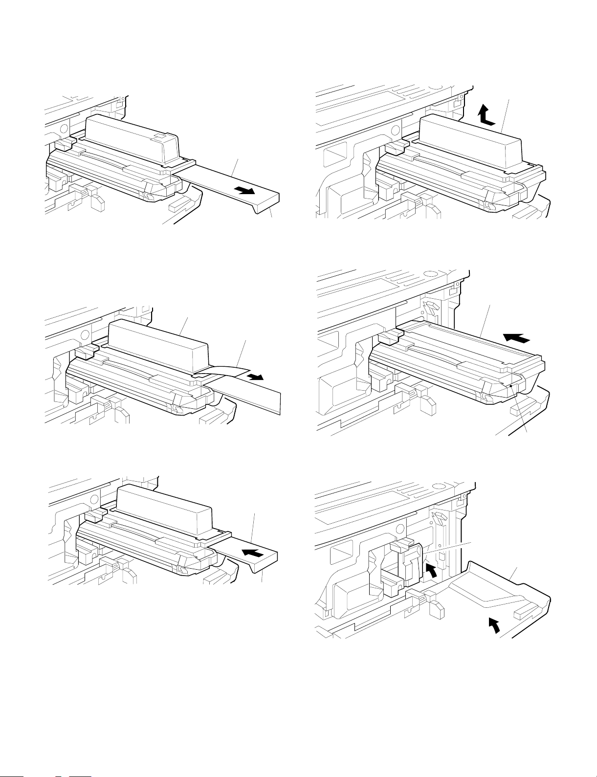
3 Hold the grip of the toner hopper shutter, and slowly pull out the
shutter fully toward you.
If the shutter won’t move, the procedure in 2 may have not
performed properly. In that case, slide the toner cartridge again
toward you until it clicks.
Shutter
Grip
6 Slide the toner cartridge to the bottom and remove it slowly.
If the shutter have not been pushed completed in procedure 5,
the toner cartridge cannot be slid. In that case, push the shutter
completely and slide and remove the cartridge.
Toner cartridge
4 While pressing the toner cartridge securely, strongly pull the toner
cartridge sheet toward you. This will supply toner into the toner
hopper. The toner cartridge sheet must be removed completely.
Then tap the top of the toner cartridge several times to feed toner.
Toner cartridge
Sheet
5 Hold the grip of the toner hopper shutter and slowly push the
shutter completely to the bottom.
Shutter
7 Hold the grip of the developing unit, and insert the developing unit
slowly to the bottom.
Developing unit
Grip
8 Close the developing unit lever, and close the front cabinet.
Grip
Developing unit lever
Front cabinet
4 – 6
Page 21
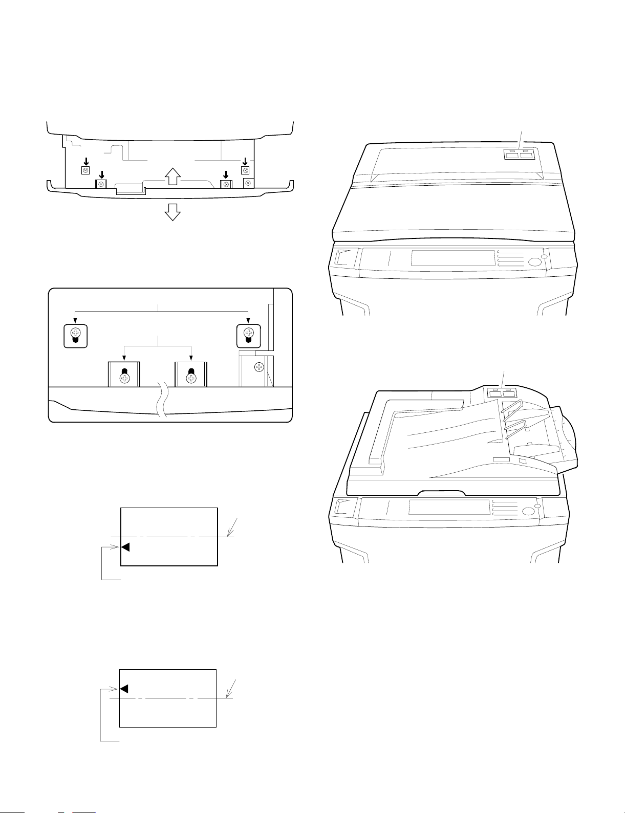
9. Center shift adjustment
10. Label attachment
There is basically no need to perform the center shift adjustment
because it is made when shipping. If the center should be shifted,
adjust in the following procedures.
Make a c opy. If the center is shifted as shown in Fig. 1 or Fig. 2,
loosen the four screws which are fixing the cassette grip cabinet.
Section b
Section a
Direction A
Section b
Section a
Direction B
[Note] When fixing the cassette cabinet, the fixing screws and the
cabinet clearance a and b are in symmetry.
Section b
Section a
A. Label attachment
Attach the magnification select label packed together with the Operation Manual to the position shown in the figure below.
• When attaching the label to the copier with the original cover.
Magnification ratio select label
• When attaching the label to automatic original feeder (SF-A15)
(1) Fig. 1
Move the cassette grip cabinet in direction A, tighten two fixing
screws (a) and two fixing screws (b) in this sequence. Make a copy
again and check the center.
[Fig.1]
Paper
center line
Image center (First image)
(2) Fig. 2
Move the cassette grip cabinet in direction B, tighten two fixing
screws (a) and two fixing screws (b) in this sequence. Make a copy
again and check the center.
Magnification ratio select label
[Fig.2]
Paper
center line
Image center (First image)
4 – 7
Page 22
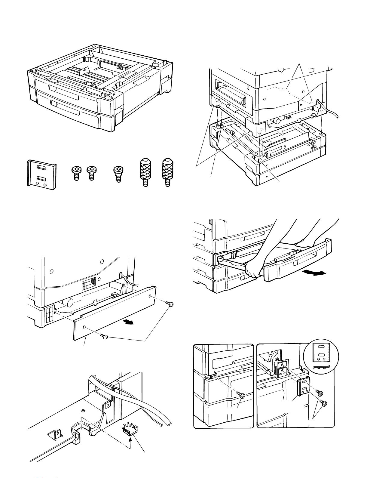
11. Optional two- stage paper feed unit
(SF-CM15) installation
Parts packed together
3 The following procedure must be performed by two persons.
Hold the grips of the copier, and insert the positioning bosses (2
positions) of the two-stage paper feed unit into the positioning
holes (2 positions) on the bottom of the copier. Then put the four
legs of the copier on the two-stage paper feed unit.
Grip
Grip
Connec tion
adjustment plate
x 1 pc.
Connection
screw A
x 2 pcs.
Connection
screw B
x 1 pc.
Connection
screw C
x 2 pcs.
Disconnect the power plug of the copier and
perform the following procedures.
1 Remove two screws which are fixing the rear cabinet on the lower
stage of the copier, and remove the rear cabinet.
Rear cabinet
Fixin g scr ew
Positioning boss
4 While lifting the lower stage tray slightly, pull it out until it stops.
Then hold the both sides of the tray and lift and remove it.
5 Attach the connection adjustment plate as shown in the figure and
fix it with two screws A. Then fix the left side with screw B.
Install the paper tray which was removed in procedure 4 to the
copier.
Positioning boss
2 Remove the notched section of the lower stage of the copier.
Notched section
4 – 8
Connection screw B
Connection
adjustment plate
Connection screw A
Page 23
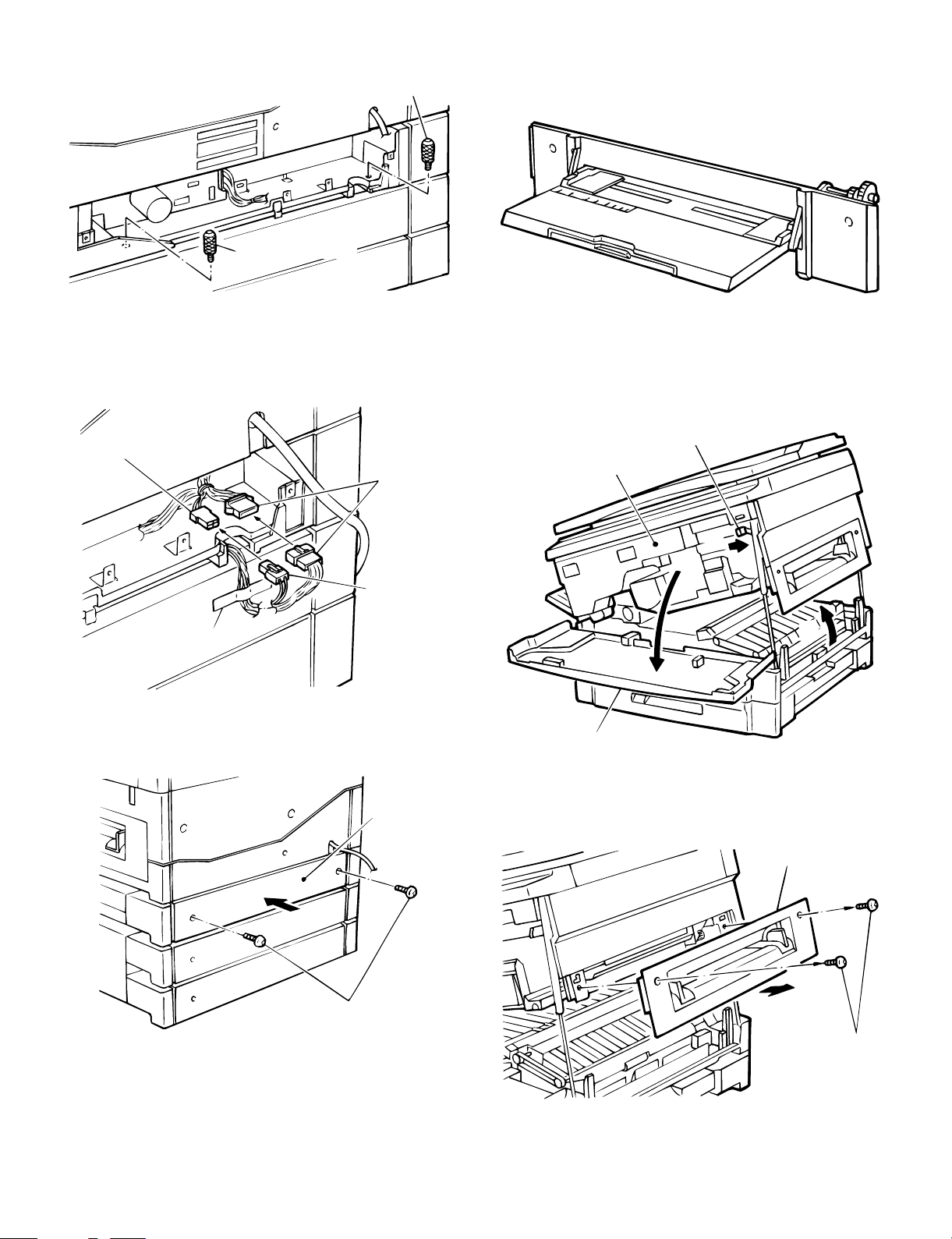
Connect the rear side of the copier with two connection screws C.
Connection screw C
Connection screw C
6 Remove the connecter which is fixed to the rear cabinet of the
two-stage paper feed unit with tape. Connect the 4P connector
and 10P connector with the 4P connector and 16P connector of
the copier.
12. Optional multi paper feed unit
(SF0MF15) installation
Disconnect the power plug of the copier and
perform the following procedures.
1 Open the front cabinet of the copier and lift the upper unit slowly
with the open/close lever.
4P connector
16P
connector
4P
connector
Fixing tape
7 Install the rear cabinet which was removed in procedure 1 to the
original postilion, and fix it with two screws.
Rear
cabinet
Body open/close lever
Upper unit
Front cabinet
2 Remove two fixing screws of the right cabinet, and remove the
right cabinet. The two removed screws are used for installation of
the multi paper feed unit to the copier.
Right cabinet lower
Fixing screw
8 Adjust according to "9. Center shift adjustment" in [4] UNPACK-
ING AND INSTALLATION.
Fixing screw
* Keep the right cabinet, which is required when the multi paper feed
unit is removed.
4 – 9
Page 24
3 Insert the positioning pins of the multi paper feed unit into the
installation holes of the copier.
At that time, first insert the rear pins, then insert the front pins.
(Check that the multi paper feed unit connecting pins are properly
connected.)
Then fix the multi paper feed unit with the two screws which were
removed in procedure (2).
Rear side
Positioning pin
Installation holes
Fixing screw
Fixing screw
Multi paper feed unit
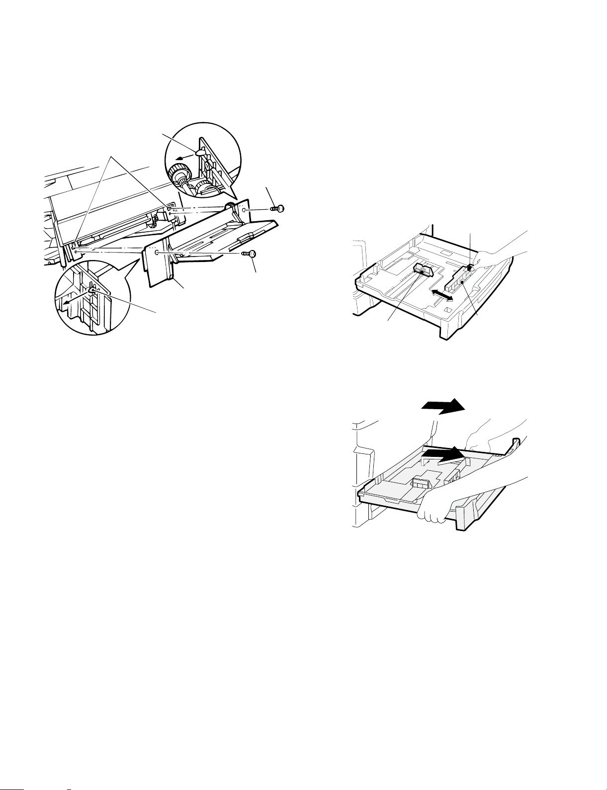
13. Tray paper size selection (Explained
with the SF-2118.)
Either of the upper and lower trays allows setting of the paper size as
shown in t he fi gu re. To select the d esi red s ize, fol low the proc ed ures
below.
(A5 size is handled as the special size. The factory setting is
A3: 11″ × 17″ size.)
1. Fit partitioning plates A and B in the tray to the
vertical and horizontal sizes according to the
paper s i ze .
Fit the plates to the scales of the paper size.
Partitioning plate A is of slide ty pe. Hold the fixing knob a nd slide
partitioning plate A to the sc ale.
Partiti oning plat e B is of in sertion type . Remove it and ins ert to the
scale po sit i on .
Lever
Positioning pin
Front side
4 With the above procedure, the multi paper feed unit installation is
completed.
* Clo se th e uppe r uni t slow ly and c lose t he fr ont cab inet. The mul ti
paper feed unit mode is automatically set.
Left guide
Front guide
2. Remove the tray.
Pull out the tray fully toward you, and tilt it upward to remove.
4 – 10
Page 25
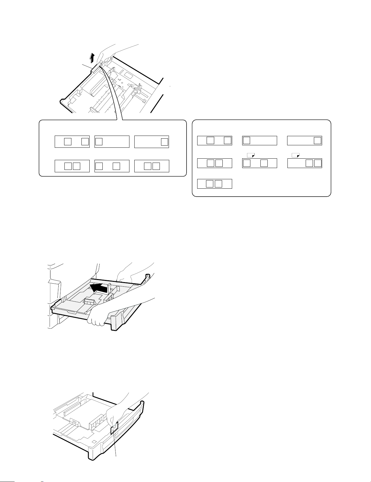
3. Remove the size block upward, and attach it to
the selected size.
Attach the size block according to the selected size as shown below:
Paper size
block
(Inch series) (AB series)
11" x 17"
x 11R
8-1/2
8-1/2" x 5-1/2"
EXTRA
Top view from front side
11x17
8-1/2
x 5-1/2
8-1/ 2" x 14 " 8- 1/ 2" x 11 "
x 11
8-1/ 2
8-1/2
x 14
8-1/2" x 11"R
8-1/2
A3
x 11R
x 14
8-1/2
EXTRA
x 5-1/2
8-1/2
8-1/2
x 11
EXTRA
(Note)
• When the tray paper size is changed, be sure to adjust the size
block. If not, the paper size display remains unchanged. (The previous size is displayed.)
4. Attach the tray.
Reverse the removing procedure. That is, tilt the tray upward and
insert into the body. Then push it in horizontally.
A3
B5
Extra
A3 B4
A4R
EXTRA
B5
EXTRA
B4 A4
A4
B5 A4R
A4
R R
A3
B5
A4
B4
B5R
A3
5. Set the papers on the tray, and select the display
of the paper size display slit.
Remove the paper size display plate, and insert it according to the
selected paper size so that the paper size indication can be seen
from the display slit.
When A5 size is selected, display "Special."
Paper size plate
4 – 11
Page 26
[5] DESCRIPTIONS OF EACH
SECTION
Descri ptions are made on the following sections:
1 Paper feed section
2 Developing section
3 Optical section
4 Process section
5 Separation/transport section
6 Fusing/paper exit section
7 High voltage section
3
4
6
5
2
1
In the case of SF-2118:
The SF-2118 is provid ed with the thr ee-way pa per fe ed syst em. Th e
tray is of the universal t y pe an d has cap ac it y o f 2 50 sheets. Th e front
loading system allows the tray to be loaded from the lower side of the
front cabinet.
(The SF-2116 ha s the two-way pape r feed system with one 250-sheet
tray and ma nual feed.)
Manual pa per feed is in the sin gle mode. The mu lti paper feed un it
(SF-MF15) is an option.
The tray has the capacity of 500 sheets (250 sheets for the SF-2116).
In addi tion to that, th e option al paper feed uni t allows loading o f 500
sheets more.
2) Basic operati ons
(Tray paper feed operat ion)
When the CPFC (Cassette paper feed clutch) turn on, the paper feed
roller shaft, t he paper fe ed roller, and the ta ke-up roller rotat e in the
direction of A. At the same time, the limiter spring moves down the
roller release arm. As a result, the take-up roller falls by its own
weight onto the paper su rface, starting paper feed .
Roll er r elease arm
Take-up
roller
1. Paper feed secti on
1) General descriptions
To r ealize th e compact design, t he front l oading system and the fo ldable multi paper feed unit (option) are employed.
Use of t he optional tw o- s ate paper fee d un it and the spar e tr ay allo w s
a varie ty of sy st e m co nf i gu r ations.
(System configuration) Example with the SF-2118:
SF-2118
Sheet
250 sheets
250 sheets
250 sheets
250 sheets
SF-CM15
(Two-step paper feed unit)
50 sheets
SF-MF15(Multi paper feed unit)
250 sheets
SF-UB15
(Spare tray)
Paper f eed ro l l er
Paper feed roller shaft
When the CPFC turns off, rotation stops and the take-up roller is
pushed up to the original position by the roller release arm spring.
(Single manual paper feed operation)
There is no special mechanism for manual paper feed other than the
manual feed paper sensing actuator and the paper guide.
(Multi manual paper feed operation)
When the MPFS (multi paper feed solenoid) turns on, the spring
clutch rotates to pr ess the take- up roller on t he paper, feeding the
paper.
5 – 1
Page 27
2. Developing secti on
1) General descriptions
(1) Two-component developer
The developer is composed of toner and carrier.
Carrier serves as a me dium for attachi ng ton er onto the ele ctrostat ic
image on the photoconductor drum.
By stirring toner and carrier, they are rubbed to be charged positive
(+) and negative (–) respectively.
Since deve loper will deter iorate to degra de copy quality, it shou ld be
replaced regularly.
(2) Two-component magnetic brush development
The rotatable non-magnetic sleeve is provided over the magnet roller
and is rotated.
Carrier forms a magnetic b rush on the sleev e surface by magn etic
force to attach toner onto the electrostatic image on the photoconductor drum.
(3) Developing bias
When the photoconductor is charged and exposed to light (exposure ), th e surfac e poten tia l (volt ag e) of the p ho tocon duct or w ill no t
be lost completely. (The residual potential remains.)
Toner is attracted to the photoconductor by this residual potential,
dirty ing the phot oconductor. As a r esult, a dirt y copy of whi te background is generated.
To prevent ag ainst this, a voltage of the same polarity and higher than
the residual potential is applied to the MG roller, preventing toner from
being attached to the photocondu ctor surface .
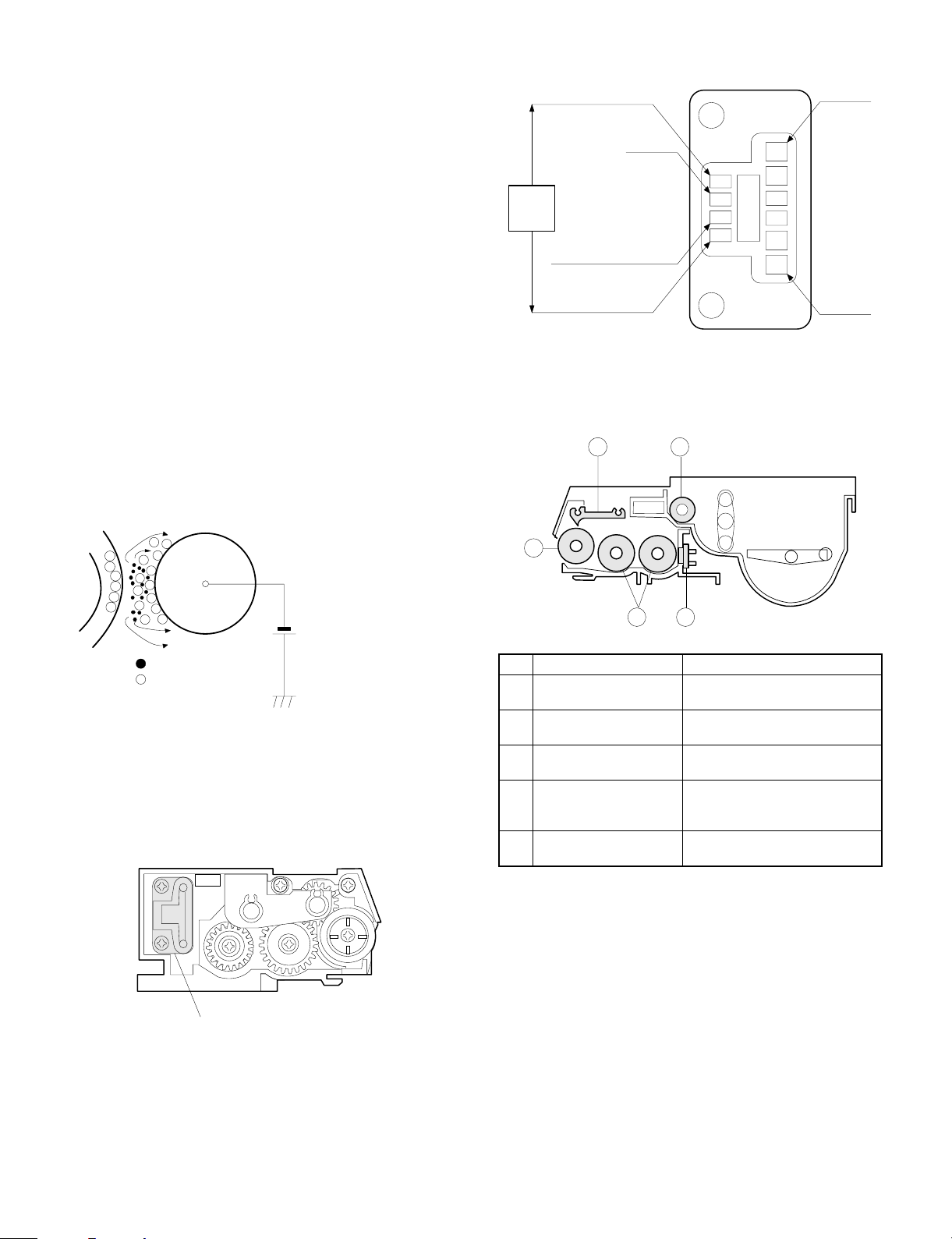
(Detail s of DV harness co nnect or)
For color identification
GND
Resistor
*For toner density sensor
GND
*Resistance value is identified by color
2) Basic composition
2
For bias
VB
4
Residual potent i al < D V B IAS
MG rolle r
DV BIAS
Toner
Carrier
Devel opi ng bia s v olt age
-200V
(4) DV harness
The toner density sensor, the developing bias, and the developing
unit identification resistance harness.
(For details, refer to [6] DISASSEMBL Y AND ASSEMBLY.)
(View ed fr om th e rear of devel oi ng uni t )
1
3 5
No. Name
Magnet roller Forms a magnetic brush of carrier
1
Developing doctor blade Limits the height of the magnetic
2
Developing MIX roller Stirs carrier in the developing unit
3
Toner transport roller Transport toner sent from the
4
Toner density sensor Senses toner density in
5
by magnetic force.
brush.
and distributes toner evenly.
toner hopper unit to the stirring
section.
developer.
DV har ness c onnec t or
5 – 2
Page 28
3) Basic operations
(Cassette paper feed)
When t he CPFC (cassette paper feed clutch) is turned on, the paper
feed roller shaft, the paper feed roller, and the take-up roller rotates in
the dire ction of A, an d the r oller re lease arm is moved downwa rd by
the limiter spring. As a result, the take-up roller falls by its weight to
reach the paper surface, feeding the paper. When the CPFC is turned
off, the take-up roller is pushed up to the position by the roller release
arm spring.
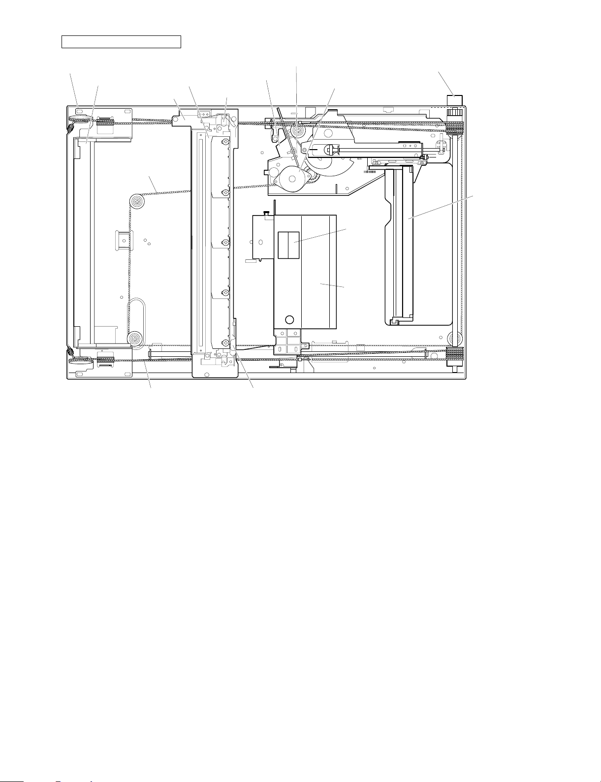
(3) Optical section
Stirring roll er
MG roller
Transport
roller(upper)
Transport
roller(lower)
DV drive unit
PS roller
Multi manual
insertion paper
feed unit
(Option)
Paper fe ed
unit
Paper fe ed
unit
Proccess
unit
Paper feed
rive unit
Main drive unit
Cleaner
unit
Transport
unit
Main motor
Fuser unit
Paper ex it
roller
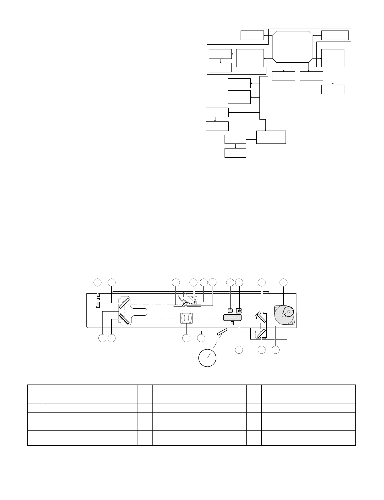
1. General description
• The optical section of this model is composed of the fixed focus
lens and six mirrors. Since the fixed focus lens is used, No. 4/5
mirror base is shifted according to the shift of the lens to change
the distance between the original and the drum (OID, Original
Image Distance) in reduction or enlargement copy.
The lens and No. 4/5 mirror unit are shifted by driving the stepping
motor with the signals from the main control PWB, allowing zooming of 151 steps in 1% increment in the range of 0.50 to 2.00.
5 6 910
• Exposure is adjusted by changing the copy lamp voltage. The AE
sensor is provided in the zoom base to sense the density of the
original.
The copy lamp light is reflected by the original to the AE sensor,
which senses the density of the original and adjust the copy lamp
light quantity according to the density.
• The exposure system is the slit exposure system by moving light
source.
3
17
151 2
14 8 12
711 1316 4
Copy lamp
1
No. 2 mirror
4
No. 4 mirror
7
No. 2/3 mirror base unit
F
Mirror motor
I
Mirror home position sensor
L
Reflector
2
No. 3 mirror
5
No. 5 mirror
8
Copy lamp unit
G
Lens/No. 4/5 mirror base drive motor
J
Automatic exposure (AE) sensor/
M
Optical system dirt sensor
5 – 3
No. 1 mirror
3
Lens
6
No. 6 mirror
9
No. 4/5 mirror base unit
H
Lens home position sensor
K
Page 29
(1) Original table
The original table is fixed. The original is set in the left center position.
Mirror base sc an spe ed is chang ed f o r zoomi ng
Enlargment
(2) Copy lamp
100V s eries: 85V, 275W
200V series: 170V, 310W
(3) Mirror
This model uses six mirrors.
No. 1 mirror is attached to the copy lamp unit, No. 2/3 mirrors are
attached to No. 2/3 mirror base, No. 4/5 mirrors are attached to No.
4/5 mirror base.
The copy lamp unit and th e No. 2/3 mir ror base unit are scanne d in
copying. The No. 4/5 mirror base is shifted in zoom copying to
change the distance between ten original and the drum.
(4) Lens (fixed focus lens)
• Construction (1 group 3 lenses)
• Brightness (F8.5)
• Focus: (195mm ±1%)
(5) Lens home position sensor (LHPS)
This sens or sen ses the le ns home position . The out put sign al of thi s
sensor is the basic signal to control the copy magnification ratio.
(6) Lens base
The lens is mounted to the lens base, which is shifted toward the
paper feed direction in reduction copy or toward the paper exit direction in enlargement copy by the lens drive motor.
Copy direction
Normal
Zooming b y c hangi ng th e le ns
and mirror positi on
Original
Reduct i o n
5 – 4
Page 30
Parts identification and functions
Mirror home position sensor
No. 2/3 mirror un it
Copy lamp unit
Lens drive wire
Reflector
Copy lamp
Lens home position sensor
AE sensor
Lens No. 4/5 mi rr or uni t
drive motor
Mirror motor
No. 4/5 mirr or uni t
Lens
Lens
unit
Mirror base wire Tempera t ure fuse
(7) Lens drive shaft
This shaft controls the optical axis of the lens in zoom copy. The lens
follows along the slide base shaft.
(8) Lens drive wire
This is to shift the lens unit and the No. 4/5 mirror base.
(9) No. 4/5 mirror unit
No. 4/ 5 mirro rs a re a ttach ed t o this unit. It is shif ted by the le ns driv e
motor to change the distance between the original and the drum
according to the zooming ratio.
(10) Mirror m otor
This st epping motor shifts the co py lamp unit and the No. 2 /3 mir ror
base. It is rotated at the rpm according to each zooming ratio.
(11) M irror home position sensor (MHPS)
This sensor senses the home position of the copy lamp unit. It is of
light t r ansmission ty pe.
(12) No. 2/3 mirror unit
No. 2/3 mirrors are attached to th is unit. It is scann ed by the mirror
motor.
(13) Copy lamp unit
This is composed of No. 1 mirror, the temperature fuse, the copy
lamp, the exposure adjustment plate, and the reflector, and scanned
by the mirror motor.
(14) Temperature fuse
This is attached closely to the reflector to prevent against abnormal
temperature rise in th e optic al syste m. If the temperatu re ri ses a bnormally, it turns off the copy lamp power directly.
100V s eries (117°C)
200V s eries (117°C)
(15) Reflector
Light from the copy lamp is reflected by the reflector to the original.
(16) Exposure adj ustment plate
Four exp osure adjust ment plat es are attac hed to the copy lamp unit
to adjust exposure balance in back and forth direction of the frame.
(17) Mirror base drive wire
This wire transmits the m irror motor p ower to th e copy lamp unit and
the No. 2/3 mirror base to scan the mirror base.
(18) Lens drive m ot or
This stepping motor drives the lens and the No. 4/5 mirror base.
(19) AE sensor
This AE sensor senses the original density by the light emitted from
the copy l am p a nd r ef lec te d by the orig ina l, c on tr o llin g the develop ing
bias. The photometric area is about 100m width at the center and in
the mirr or base scannin g direction.
The element is photo diodes.
5 – 5
Page 31

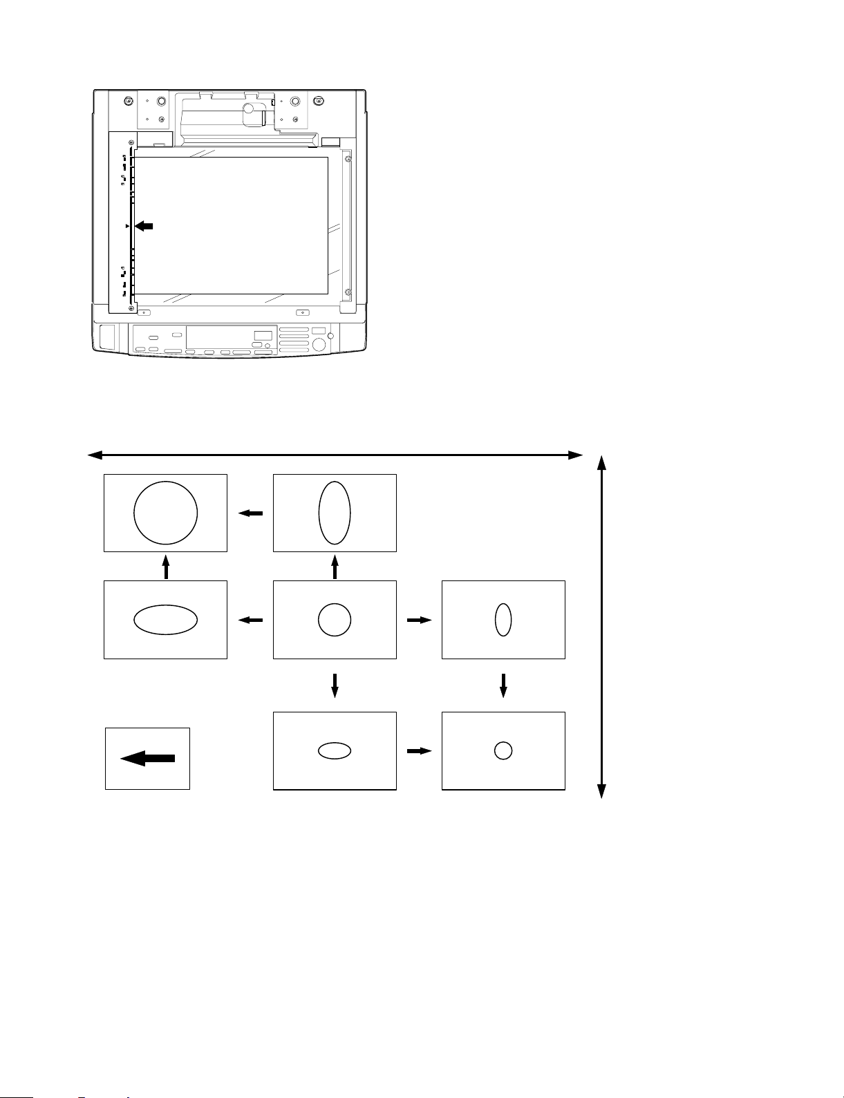
(20) Original size sensing
g
g
The origin al siz e is sensed by the orig in al interrupti on system.
The LED in the rear frame side emits light to the table glass surface.
The original interrupts this light, and its size is detected.
Light emit
Li
ht receivin
Table glass
2. Basic operations
(Positions of the o riginal, the lens, and the image in each magnification ratio)
Normal: The distance between the original set on the table glass and
the lens is equal to the distance between the lens and the
drum, resulting in the equal size of the original and the
image.
Mirror base scan speed
Lens and mirror positions
are changed to adjust the
Copy paper
magnif ic ati o n ra t io
feed derection
Mirror scan speed is cahnged to adjust the magnification ratio
Mirror scan sp eed Drum rotation speed <Mirror scan speed
Enlargement
Original
Reduction
Enlargement: Compared to the normal copy, the lens is nearer to the
original and the distance between the original and the
lens is shorter.
The distance between the No. 4/5 mirror unit and the
lens is greater, and the distance between the lens and
the drum is also greater.
The distance between the original and the exposure
surface of the drum is greater than that in the normal
copy.
Reduction: Compared to the normal copy, the lens is nearer to the
drum, and the distance between the original surface and
the lens is longer.
The distance between the lens and the exposure surface
of the drum is shorter.
The distance between the No. 4/5 mirror unit and the
lens is greater.
The distance between the original and the exposure surface of the drum is greater than that in the normal copy.
(Copy lamp control in each copy density)
[MAX. 83V(166V) ]
80
70
CLV
(Copy lamp
application
voltage)
Execute Sim 46-01 to de termine the copy lamp applicatio n voltage
(CLV) in EX1 and EX5.
Then divide the difference between the voltages of EX1.0 and EX5.0
into nine.
The application vol tage of the copy lamp in each expo sure level is
determined by varying the ON timer duty of the copy lamp ON control
signal.
(V)
60
50
40
EX1
23
[MIN. 45V(90V)]
EX5
4
• Photo density copy mode
Make the same control procedures as the manual density copy
mode.
The image density is controlled by lowering the grid bias voltage of
the charging charger. To maintain the reproduction quality in half
tone, the ON time duty of the copy lamp ON signal is made shorter
than in the manual density copy mode. (The application voltage is
lower.)
5 – 6
Page 32

(Optical system dirt correction)
This mo del pe rform dirt correc tion by cha nging t he cop y lamp intensity a ccord ing t o the d irt degr ee in th e optic al s ystem (t he co py la mp
unit, No. 1 mirror, No.2 mirror, No.3 mirror) to prevent against remarkable de grading of copy quality.
The reference value is the AE sensor output value which is obtained
when th e reference plate is e xposed with th e copy lamp voltage of
67.0V (134.0V) at power ON.
This value is checked with sim 44-08, 09.
CLV
Sim46
Reference plate (Glass holder)
CPU
Reference value
>Measured value
Correction data output
Table glass
Copy lamp light quantity "UP"
Automatic exposu re
sensor
100 200 300 400 79.8K 80K
CLV + (0.7)
(1) Setting the reference value for optical system correction.
Reference plate (Glass holder)
CPU reference value
setting
1 Clean the optical system at every maintenance.
2 Perform Simulation 46-1.
(The previous data are cleared.)
3 After completion of Simulation 46-1, when performing the first
mirror initialization, measure light quantity of the copy lamp.
Obtain the average value from the four measurement values and
use the average value as the reference value for correction.
800ms
Table glass
Automatic exposu re
sensor
1234
(2) Dirt corr ection
Reference plate (Glass holder)
CPU
Referenc e v a lue
>Measured value
Correction data output
1 Measure light quantity when performing mirror initialization.
2 Store the correction data into memory.
3 Reset the register inside the CPU.
Table glass
Copy lamp light quantity "UP"
Automatic exposu re
sensor
CL
Light quan t i t y
measurement
Obtain the average value of four AE sensor values, and store it.
5 – 7
Page 33

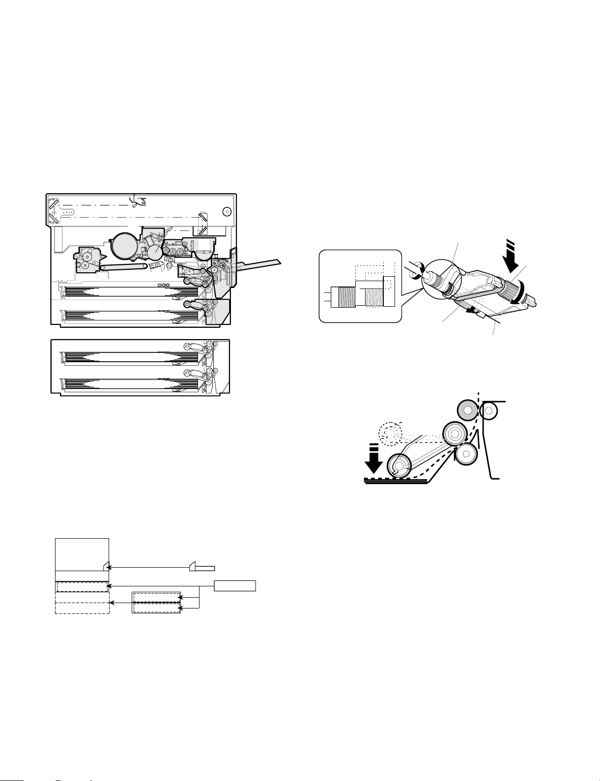
(4) Copy process
This model basic process and structure
• The Scorotron method is used to evenly charge the photoconduc-
tor surface to the given potential in the charge process. The
corona wire regularly used is now replaced with a new corona
charge mechanism that employs the 0.1mm thick stainless steel
saw teeth plate, in order to suppress ozone generated when the
oxide molecule in air is ionized.
• Considering the service efficiency, the process separation
mechanism is adopted.
• To prevent high voltage leakage by the loose corona charge unit, a
one-touch stopper mechanism is adopted.
Stirring roll er
MG roller
Transport
roller(upper)
Transport
roller(lower)
DV drive unit
PS roller
Multi manual
insertion paper
feed unit
(Option)
Paper fe ed
unit
Paper fe ed
unit
Proccess
unit
Paper feed
rive unit
Main drive unit
Cleaner
unit
Transport
unit
Main motor
Fuser unit
Paper exit
roller
(1) Photoconductor
• This model uses OPC (organic photoconductor) as photoconduc-
tive material. (φ50 mm)
OPC la ye r CTL (Ele ctr ic char g e moving layer)
CGL (Electric charge gener ating layer)
Aluminum layer
5 – 8
Page 34

(2) Process diagram
High voltage unit
Original
Copy lampMirror lens
Cleani n g bl ad e
Waste toner collection
Paper exit
Discharge lamp
Main corona unit
Discharge lamp
Fusing
Heat r olle r
Heater lamp
Main corona unit
Discharging
Cleaning
Separ at ion
Separation corona unit
High voltage unit
Charging
Separation
Blank lamp
Exposure
Transfer
Transfer charger
High voltage unit
Discharge
Development
Drum u ppe r
image /paper
synchronization
Blank lamp
Developer
Resist roller
Toner
Paper feed roller
Transportroller
Image forming process
Paper transport path
High voltage unit
Manual paper feed
Paper cassette
Cleaning blade
Seper ati on pa w l
Seperation corona unit
Developer unit
MG roller
Resist roller
Transfer corona unit
5 – 9
Page 35

(1) Details of image forming process
Step 1 (Main Char gi ng)
By negative discharging of the main charger, uniform negative charges are applied to the O PC drum surface.
The OPC drum surface potential is controlled by the screen grid
voltage to maintain the grid voltage at a constant level.
• When the drum surface potential is lower than the grid voltage,
electric charges generated by discharging of the charger go
through the screen grid to charge the drum surface potential until it
becomes equal to the grid voltage.
• When the drum surface potential virtually reaches the grid potential
level, electric charges generated by discharging of the charger
flows through the electrode of the screen grid to the high voltage
unit grid voltage output circuit, thus always maintaining the drum
surface potential at a level virtually equal to the grid voltage.
• The main corona unit employs the scorotron system to charge the
photoconductor surface to a certain level uniformly.
In addition, the conventional corona wire is replaced with the
corona charging mechanism by saw-teeth plate (stainless steel
plate of 0.1 mm thick). In corona discharge, oxygen molecules in
the air are ionized to generate ozone (O3). The mechanism restrict
the generation of ozone.
Main corona unit
Main corona unit
Blank lamp
High voltage unit
Screen grid
CTL
CGL
OPC drum
Aluminum
layer
Step 2 (Exposure)
Light from the copy lamp is radiated on the document, and the optical
image of the document is reflected by the mirrors and projected
through the lens to the OPC drum.
The ligh ter p orti on of th e docu men t refl ec ts more light ( high int ensit y)
to the OPC drum , an d the d ark er por tion o f the docu ment ref lect les s
light (l ow intensity) to the OPC drum. Positive or ne ga ti v e ch ar g es ar e
generated in the CGL of the OPC dr um where lights are radiated.
Negative charges generated in the CGL move towards the positive
charges in the aluminum layer generated in step 3. While the positive
charges in the CGL move towards the negative charges on the CPU
drum surface generated in step 3. Therefore, positive charges and
negati ve ch arg es a re n eutr aliz ed in the alum inum laye r an d th e OPC
drum surface at the light radiating position, decreasing the OPC drum
surface potential. The CGL electric charge generating amount increase s in proport ion to the d ocument density, that is, refl ected ligh t
intens ity (the OPC drum surfac e intensity). Ther efore, electric ch arges are gener ated les s in th e CGL layer cor respon ding to the lig hter
density of document (higher intensity of the OPC drum surface), and
a greater quantity of the negative charges on the OPC drum surface
is neutralized, decreasing the O PC drum surf ace potentia l more.
Discharge lamp
Cleani n g bl ad e
Seperation pawl
Seperation corona unit
On the contrary, electric charges are generated more in the CGL
layer corresponding to the darker density of document (lower intensity
of the OPC drum surface), and less quantity of the negative charges
on the CPU drum surface is neutralized, decreasing the OPC drum
surface less. Therefore, the OPC drum surface potential corresponding to the lighter portion of the document is lower, and that corresponding to the darker portion of the document is higher. Latent
static-electric ity images ar e formed in the above manner.
Transfer corona unit
Developer unit
MG roller
Resist roller
5 – 10
Page 36

CTL
CGL
Low intensi ty in
the area corresponding to the
darker density
portion of the
document
Medium intensity
in the area cor responding to the
medium dens it y
portion of the
document
HIgh intensity in
the area corresponding to the
lighter density of
the document
Aluminum
layer
OPC drum
Surface pot e nt i al
(High)
CTL
CGL
Surface
potential
(Medium)
Surf ace
potenti al
(Low)
Aluminum
layer
OPC drum
Step 3 (Develop me nt )
Ton er is atta ched to t he latent static-elec tricity ima ges on th e drum
surface to change them to visible images. The two-component magnetic brush development system charges toner positively by friction
with car riers , and toner is attac hed t o nega tive cha rges on the d rum
surface. The potential in the darker document projecting area (low
intens ity) is high (m uch negative c harges) and a ttracts more toner.
The potential in the lighter document projecting portion (high intensity)
is low (less negativ e charges), an d attracts less toner.
Discharge lamp
Cleaning bl ade
Seper ati on pa w l
Main corona unit
Seperation corona unit
Blank lamp
Devel oper u nit
MG roller
Resist roller
Transfer corona uni t
OPC drum
CGL
Aluminum layer
Higher surface
potential
(Much negative
(charges)
Medium surface
potential
(Less negative
(charges)
Lower surface
potential
(No negative
(charges)
CTL
MG roller
-200V
High v ol t age u ni t
bias volt ag e
At that time, a bias of –200V is applied to the MG roller (magnet
roller), which is provided for preventing toner from being attracted by
the resi du al vol tag e (abo ut –80V t o –1 00V ) in the ligh te r port ion aft er
exposure.
Discharge lamp
Cleani n g bl ad e
Seperation pawl
Main corona unit
Seperation corona unit
Blank lamp
Developer unit
MG roller
Resist roller
Transfer corona unit
5 – 11
Page 37

Step 4 (Transfer)
The transfer paper is charged higher than the OPC drum surface
potential by s tr on g negati ve discharge of the tran sf er c harger, makin g
the binding force between the transfer paper and toner stronger than
that between the drum and toner, attracting toner to the transfer
paper.
Aluminum
layer
CGL
CTL
Transfer corona unit
High voltage unit
OPC drum
Toner
Transfer paper
Seperation pawl
Step 5 (Separati on)
After transfer, the copy paper and the drum are negatively charged.
Since, however, the negative potential of the copy paper is higher
than tha t of the drum, a attract ion for ce is appl ied betw een the dr um
and the copy paper. To avoid this, AC corona is applied to the copy
paper by the separation charger to decrease the copy paper potential
to the same level as the drum surface potential. The attraction between t he copy pape r and the drum is weakened by this, a llowing
separation of the copy paper by its own extending force. If the copy
paper is not separated by the separation charger, it is separated by
the separation pawl mechanically.
Discharge lamp
Cleani n g bl ad e
Main corona unit
Seperation corona unit
Blank lamp
Developer unit
MG roller
Resist roller
Transfer corona uni t
Aluminum
layer
CGL
CTL
High voltage unit
Seperation corona unit
OPC drum
Toner
Transfer paper
Discharge lamp
Cleaning bl ade
Seper ati on pa w l
Main corona unit
Seperation corona unit
Blank lamp
Developer unit
MG roller
Resist roller
Transfer corona unit
5 – 12
Page 38

Step 6 (Cleaning)
Residual toner on the drum is removed by the cleaning blade. The
removed toner is sent to the waste toner container by the waste toner
transp ort screw.
CGL
Blade Aluminum layer
CTL
Discharge lamp
Main corona unit
Blank lamp
Residual toner
OPC drum
Step 7 (Dischargi ng)
When the OPC drum is exposed to the discharge lamp light, positive
and negative charges are generated in the OPC drum CGL. The
negati ve charges ge nerated in th e CGL move towards the residual
positiv e char ges in the alu minum layer, wh ile the posit ive cha rges i n
the CGL move towards the residual negative charges on the OPC
drum s urface. The refore, t he positi ve and the ne gative cha rges are
neutralized in the aluminum layer and on the OPC drum surface,
removing the residual charges on the OPC drum surface. As a result,
the OPC drum surface potential becomes 20V ∼ 30V.
Dis charge lam p
Cleaning bl ade
Seperation pawl
Seperation corona unit
Main corona unit
Developer unit
MG roller
Resist roller
Transfer corona unit
Blank lamp
Resi dual charge
CTL
CGL
Aluminum layer
OPC drum
Resi dual charge
Discharge lamp
Cleani n g bl ad e
Seper ati on pa w l
Seperation corona unit
Devel oper u nit
MG roller
Resist roller
Transfer corona unit
5 – 13
Page 39

(4) Transition of photoconductor surface potential
Develop
Charge Exposure
BL
-730V
Dark area
-215V
Devel opi ng bia s v olt age
Light area
(5) Photoco nduc t or drum s e nsitivity correc t ion
In this mod el, f all i n sen sitiv ity due to long use o f th e pho tocon du ctor
drum is co rrected by th e copy lamp lig ht intensi ty to preven t against
considerable change in copy quality.
The photocondu ctor drum se nsitivity fall co rrection is per formed as
follows:
Cleaner
OPC drum
Develop
Change the tickness of the carrier transport layer (CTL).
By the developper.
By the cleaner blade.
Residual po tentia l
(NEW)
Transfer Separate
Clean
(USED)
DL
CLV
CLV + 2 counts
(Sim46)
CL(V) + (0.33V x 2)
Sim46
(6) Process control function
[Summary]
The process control function detects the density of the standard toner
image formed on the photoconductor, the density of the initial image
and controls the charging grid voltage so that the same level as the
initial imag e den si t y is pro vid ed .
That is, the process conditions are established and the high voltage
output and exposure level are controlled to stabilize the toner density.
In this model, the density sensing level is automatically set.
CTL
CGL
5K0 10K 15K 20K 25K 70K 75K 80K
CTL
CGL
F
R
MAin control PWB
CPU density
judgement
Drum c ounter
5 – 14
I/O MC grid
output selecti on
High voltage PWB
MC grid bias
output (density
correction)
in each mode
(Light quan tity
correction)
Page 40

Process control
1 Toner patch images are formed on the photoconductor surface
under the three process conditions (MC grid bias voltage).
At the first process control, a toner parch image is formed with the
reference grid voltage –410V as the center and ±30V. At the
second or later process control, the MC grid bias voltage determined at the former process control is used as the center, and a
toner patch is formed under the process condition of ±32V to the
center value.
2 Measure the three toner patch images formed in the above and
the drum surface with the process density sensor to obtain the
relations.
Surface
472V
440V
408V
Bias
1
2
BV
3
3
2
PV
1
IDPAT =PV 2 x 20
IDPAT =PV 3 x 20
Toner
image Surface
1
Drum 1/2 rotation 2/2 rotation 3/2 rotations
1IDPAT =PV 1 x 20
2
3
Toner
image Surface
2
IDBAS =BV 1 x 20
1
2
IDBAS =BV 2 x 20
3
IDBAS =BV 3 x 20
Toner
image
3
Surface
The grid voltage value where the same density level as the reference level is obtained is displayed by Sim. 44-9 "a". This value is
displayed with 50 as the center in the range of 0 ~ 99 in integer
numbers. The correction for 50 is 0V (–410V), and the correction
for 58 is +30V (–442V).
4 When the MC grid bias voltage is corrected by the process con-
trol, the corresponding light quantity is calculated to control the
copy lamp.
To correct the MC grid voltage, the delta value of the sensitivity
level when the initially recorded reference grid voltage is –440V
and the MC grid voltage where the same density is obtained in
process control is fed back to the MC grid voltage of each mode.
Process control timing
In the SF-2035, the process control is performed in the following
timing:
1 When the main switch is turned on and the first copy is made:
2 At every specified copy quantity (First copy after 1,000 copies)
Judged by the total counter.
The correction is reset by Simulation 25-2.
3 After the specified time after turning on the main switch. (First
copy after 44, 60, 120, 180 min)
Drum marking
In this mo del, a toner patch im age is for med in the sa me posit ion on
the photoconductor drum surface to improve the accuracy of the
process control.
A marking is provided on the drum and the marking is sensed before
forming a toner patch image. If the marking level is not sensed, the
devel oping lamp bli nks and the trouble code (F2-32) is displayed.
BVS: Sensor detection level on the photoconductor drum surface
PVS: Sensor detection level with the toner patch image
Obtain the above two levels from the calculation formula and record
them as the reference values.
A. STD BA: Reference level when detecting the drum surface
→ STD BA = BTS x 20
B. STD PA: Reference level when detecting the toner patch image
→ STD PA = PTS x 20
In the density correction, the process conditions are determined
so that the ratio of the reference levels
may be maintained at constant.
STD PA
set in the above
STD BA
3 Obtain the MC grid bias voltage from the reference level ratio.
PA
( ӊ)
BA
ID PAT3
3=
STD PA
STD BA
3
2
1
GB PAT
-440-410-380
2=
1=
ID BAS3
ID PAT2
ID BAS2
ID PAT1
ID BAS1
MC grid bias voltage
In the SF-2214/2118, the absolute value of the output of the density sensor is not directly used for control calculation, but the ratio
of the sensor output value (BA) on the drum surface and the
sensor output (PA) of the toner patch image is used for control
calculation.
* The grid bias value is obtained so that the ratio of the drum
surface level and the sensor level when forming patch level and
the sensor level when forming patch images is 200:40.
Though , theref ore the lig ht quantity of t he r ef lection type sens or is
varied by dirt or deterioration, the ratio (PA/PB) will not be affected
by change in light quantity to provide stable control.
R
6mm x 7mm
F
Basic struct ure
Photoconductor drum: The 65mmφ ground plate of the OPC
Blank lamp: The non-image area is exposed by the
Discharg e lam p: Eight bulbs cas t light over the drum s ur-
Cleaning mechanism: The cleaning blade removes the toner
Main corona: The saw teeth corona charge method is
Enforced separation
mechanism:
drum is on the rear frame side of the drum
unit so that it contacts the drum locator
pin.
light from the blank lamp to erase the
positive potential outside the drum CTL.
Use of the latchet simplifies the lamp position adjustment.
face to erase the posit ive potential in CTL .
Ventilation hole provided in the drum
frame releases heat from bulbs.
remaining on the drum surface. The blade
always rests on the drum surface.
used. Use of the screen grid maintains the
even charge potential over the photoconductor surface.
Using tw o pieces of separat ion pawl, the
copy pa per st uck over t he dru m surfa ce is
forced to separate from the drum surface.
5 – 15
Page 41

Waste toner transport
mechanism:
The waste toner is passed through waste
toner transp ort scre w 1 and wast e toner
pipe 2 to waste toner bottle 3.
Waste toner bottle 3 is rotated by the
main drive gear via gear 4 to transport
toner evenly.
When the waste toner bottle is full of
waste toner, the rotatio n torque of gear 4
is increased to escape gear 5 in the
arrow direction A, and switch 6 is turned
on at the same time to light the waste
toner replacement lamp.
4
5
6
(5)TRANSPORT/FUSING SECTION
1) General
The SF-2116/2118 allows transport of paper of max. A3 (11" x 17")
and min. A5 (8 1/2" x 5 1/2").
After images are transferred on the paper, the paper is separated
from the drum by the separation pawl and transported to the fuser
section by rotation s of the resist roller and the tr ansport belt.
The dru m separation pawl is provid ed under the p rocess unit. It is
made by turning on (separating) the solenoid inside the main drive
unit.
2) Basic compo si tion and functions
1 Transport belts (2pcs)
The transport belts are provided with notches to hold paper rear
ends.
Paper
Feeding direction
2
3
1
A
Transport belt
(6) Fusing paper exit section
3
1
1 Upper heat roller
The upper heat roller is teflon-coated.
2 Lower heat roller
A silicone rubber roller is used.
3 Separation pawl
The upper heat roller is equipped with four pawls which are teflon
coated to reduce friction.
the lower heat roller is equipped with two pawls.
4 Upper/lower separation function
The upper and lower heat roller sections are separated by rotating
operations with the transport roller as a fulcrum, providing better
serviceability.
5 – 16
2
Page 42

5 Drive system division
The fuser unit is rotated by the main drive unit. In case of manual
rotation of the fuser unit to remove paper jam, however, excessive
loads may be applied to the gears. To prevent against this, the
pressure of the upper/lower heat rollers is reduced when the
machine clamshells are opened. In addition, the fusing gear is so
constructed that the drive is not transferred to the drive system.
Stirring roll er
MG roller
Transport
roller (upper)
Transport
roller (lower)
DV drive unit
PS roller
Multi manual
insertio n p ap er
feed un it
(Option)
Paper feed
unit
Paper feed
unit
Proccess
unit
Paper fe ed
rive unit
Main drive unit
Cleaner
unit
Transport
unit
Main motor
Fuser unit
Paper ex it
roller
Thermo control
Heat roller surface
temperature detection
The heat roller is heated by the
heater lamp.
(When the heat roller surface
CPU
Thermistor
Heat r olle r
Heater lamp
temperature is 190 C˚ or lower,
the heater lamp is actuated)
[8] HIGH VOLTAGE SECTION
1) General
There are three kinds of coronas; the main corona, the transfer
corona, and the separation corona. The main corona employs the
scorotron system, where the drum surface is evenly charged with
negative charges controlled by the screen grid between the corona
and the drum. The transfer corona is used to transfer toner images on
the drum to th e cop y pape r. A high, negat ive voltag e is app lie d to the
rear side of the paper. The separation corona applies AC corona to
the copy paper to eliminate potential difference with the drum to allow
separation of the pap er.
The o utput vol tage of t he main ch arger and the transfe r charger is
supplied by transformer 1. The feedback current from the transfer
charger is controlled to be constant and outputted to the main
charger.
2) Basic composition
(1) Main (cha rging) corona – High voltage
transformer (MHVG)
Grid voltage Developing bias voltage
Standard mode –750V
Photo mode –500V –200V
TSM mode –650V
(2) Main transfer corona – High voltage transformer
(THVG)
–41µA (Electro de sheet front-rear balance difference: max. 7.0µA)
(3) Separation corona – High voltage transformer
(SHVG)
AC4KV ±0.1KV
(Heater trouble)
Self diag display
Thermostat
Contact open (* )
Abnor m al h i g h
tem per atur e
• Abnormally high temperature (H3) 240°C or upper
• Abnormally low temperature (H4)
• Thermistor disconnection (H2)
* Wh en the thermostat cont act is open, it is re quired to press the
reset button in the upper side of the thermostat. (The contact is not
reset automatically.)
5 – 17
Page 43

[6] DISASSEMBLY AND ASSEMBLY
The descriptions are divided into the following sections.
1. Paper feed section
2. Transport section and power section
3. Fusing section
4. Optical system
5. SPF section
6. Drum section
7. Developing section
8. Operation panel section and intermediate cabinet
9. major parts on the frame side
10. Multi paper feed unit (SF-MF15, option)
11. Two-stage paper feed unit (SF-CM15, option)
1. Paper feed section, transport section,
power section
1-1. Paper feed unit
1 Open the front cover and lift up the upper clamshell. Remove two
fixing screws of the manual paper feed section, and remove the
manual paper feed section.
(Note for assem bly)
1) There is the 8-pin connector on the back of the rear frame side.
When assembling it, carefully insert.
2) The belt must be on the paper feed unit gear and the resist roller
gear.
1-2. Paper feed roller ass’y removal
1) Remove the rear frame side electromagnetic clutch connector.
2) Remove the front frame side stopper and the bearing.
3) Remove the roller release arm spring from the paper feed frame.
2 Remove the four fixing screws (M4 x 10 x 1pcs, step screw x 1 pc)
of the paper feed unit, and lift the rear frame side of the paper
feed unit and remove it. (Since there is the 8-pin connector on the
back of the rear frame side, it requires some force to remove.
Carefully pull it out straight.)
4) Remove the rear frame bearing, and one side of the paper feed
roller ass’y will be disengaged. To remove the ass’y completely,
remove the E-ring.
(Note for assem bly 1)
With r oller rel ease arm s pring A hooke d on th e spring notch, att ach
the pa per feed r ol l er ass’y to t he paper feed unit, a nd hook the sp r in g
on the paper feed frame.
A
A
6 – 1
Page 44

(Note for assem bly 2)
When a tta ching the pa per f eed sect ion rolle r as s’y, adjust so t hat t he
paper fee d roller clutch an d the PS fron t roller ass’y clutc h projec tion
face toward the paper feed side.
1-4. Separation roller
1 Remove the paper feed unit and remove the separation roller.
1-3. PS front roller ass’y
1 Remove the paper feed unit. (For the details, refer to the 1-1.)
2 Disengage the hook section of the front frame side bearing,
remove the connector on the rear frame side, and remove the PS
front roller ass’y from the paper feed frame.
1-5. Paper feed roller, take-up roller
1 Remove the paper feed roller, and remove the take-up roller.
2 Remove the roller holder, the stop ring, the bearing, and the paper
feed roller.
6 – 2
Page 45

(Note for assem bly)
Attach the paper feed roller so that the one-way clutch is on the rear
frame side. (Be careful of the direction.)
Attach the roller holder as shown below.
One-way clu tch side
1-6. Lower paper feed unit
(SF-2118 only): Perform similarly for the optional
two-stage paper feed unit.
Remov e two screws an d remove the lo wer paper feed unit.
1-7. Lower separation roller
(SF-2118 only): Perform similarly for the optional
two-stage paper feed unit.
Remove the lower paper feed unit. Refer to 1-6.)
1
2 Remove the paper feed frame. (4 screws, 2 connector)
3 Remove the separation roller.
1-8. Transpo rt roller
(SF-2118 only): Perform similarly for the optional
two-stage paper feed unit.
Remove the lower paper feed unit. (Refer to 1-6.)
1
2 Remove the stopper, slide the bearing, and remove the transport
roller.
1-9. Lower paper feed roller/take-up roller
For removal of these rolls, refer to 1-2 (Paper feed roller ass’y) and
1-5 (Paper feed roller, take-up roller).)
2. Transport unit
2-1. Resist roller, transfer roller
1 Open the front cover.
2 Release two lock pawls of the TC case, and lift the front side of
the TC case to remove.
6 – 3
Page 46

3 Remove the hook of the front frame side bearing, and lift it up to
remove it toward the upper frame side. Remove the rear frame
side connector, and slide and remove the resist roller ass’y toward
the rear frame side.
TC/SC case
4) When attaching the resist roller ass’y to the copier, attach over the
upper side of the PS roller lower mylar, then rotate the roller to set
the mylar to the normal position. (If the mylar is deformed, it may
cause paper jam. Replace it if deformed.)
PS mylar
4 Remove the clutch and the gears as shown below.
(Note for assem bly)
1) Attach so that the resist roller clutch projection is on the paper exit
side as shown in the figure below.
2) Arrange the cable and the power grounding wire from the resist
roller clutch as shown in the figure below.
3) Hook the hook section of the TC case as shown below.
2-2. Transpo rt belt
1 Remove the fusing unit.
2 Remove the TC case.
3 Disengage the transport belt drive shaft holder on the TC case
side, then disengage the drive shaft on the paper exit side and
remove the belt.
(Note for assem bly)
There is a mark ( î ) on the transport belt. Set so that the tip of
1
the mark faces toward the paper exit direction.
2 Be careful of the installing direction of the transport belt drive
shaft.
6 – 4
Page 47

3. Fusing section
3-1. Fusing uni t removal
1 Open the front cover.
2 Push the open/close lever down to the right side, and slowly open
the upper unit.
3 Remove the fixing screw of the fusing connector cover and
remove the cover.
4 Remove the fusing unit hanging wire from the copier frame and
remove two connectors from the unit.
(Note for assem bly)
When removing the unit fro m the copier, ba careful not to scratch the
photoconductor drum. Be careful not to break the actuator of the
paper exit sensor (POD).
3-2. Heater lamp replacement
1 Remove the fusing cover fixing screw (1 pc.), and slide the cover
to the front side to remove.
2 While pressing the Fasten terminal projection connected to the
thermostat, remove the lead wire from the connection section.
3 Remove the fixing screw of the lamp holder on the upper side of
the rear frame, and remove the holder.
5 Remove the stop ring and remove the unit.
4 Pull out the heater lamp from the front frame side.
For assembly, reverse the disassembly procedures.
3-3. Upper heat roller ass’y removal
1 Remove two fixing screws of bearings of the front and the rear
frames.
2 Push the paper guide down to the paper exit side and separate
the separation pawl from the roller and fix it.
3 Rotate the bearing fixing screws about 45 degrees downward and
remove the ass’y.
For assembly, reverse the disassembly procedures.
6 – 5
Page 48

3-4. Upper separation pawl replacement
1 Remove the fusing unit, and remove the cover.
2 Put the fusing unit so that the paper guide is on the lower side of
the fusing unit (the separation pawl is on the upper side).
3 Remove the tension spring, hold the separation pawl tip and
remove it from the supporting section, and remove it from the unit
by tilting.
For assembly, reverse the disassembly procedures.
3-6. Lower separation pawl replacement
1 Remove the fusing unit.
2 Remove the lower heat roller.
3 Remove three screws and remove the lower separation pawl unit.
3-5. Lower heat roller replacement
1 Remove the fusing unit.
2 With the lower separation pawl upright, slide it to he rear frame
side and keep the lower separation pawl upright.
3 Remove the lower heat roller together with the bearing.
For assembly, reverse the disassembly procedures.
5 Remove the tension spring, hold the separation pawl tip to remove
it from the supporting section, and remove it by tilting.
(Note for assem bly)
Assemble so that the lower separation pawl is on the upper side of
the lower hea t roller. (At that time, return th e separation pawl which
was set upright in procedure (2).)
6 – 6
Page 49

3-7. Thermistor/thermostat removal
1 Remove the fusing unit.
2 Remove the fusing cover, and remove the thermistor/thermostat.
(B)
’² õ”Â
* Note for assembly
• Check that the thermistor center is in contact with the heat roller.
• Clean the thermistor surface with alcohol to remove foreign
materials.
4. Optical system
The o ptical system is an integrated f inish produc t delivered b y the
maker as stated in the previo us section . Th e r e pl acement p rocedures
for the major parts in the optical system are described here.
1) Copy lamp replacement
1 Remove the OR guide, and remove the table glass. (2 screws)
2 Slide the copy lamp unit to the notch at the rear of the upper
cabinet. Push the copy lamp electrode (section A) in the arrow
direction B, and remove the lamp.
Do not move the optical adjustment plate. (If it is moved, the light
balance will go wrong.)
Install so tha t the pr ojecte d porti on of t he copy lamp is ne ar the re ar
side as shown above.
2) Mirror base wire replacement and adjustment
A. Copy lamp unit remova l
1 Remove OR guides R/L, and remove the table glass.
Note: Be careful of the installing direction of the copy lamp.
6 – 7
Page 50

2 Remove the operation panel, the upper cabinet R, and the right
cabinet.
3 Remove the dark box cover upper.
B. Mirror base wire removal
Remove the upper cabinet L, and the left cabinet.
1
2 Remove the mirror wire spring from the groove on the left side of
the optical base plate.
4 Manually move mirror base B. (Within the range where the wire
fixing plate fixing screw can be removed.)
5 Remove the wire fixing plate in the front/rear frame side of the
copy lamp unit, and remove the wire from the side plates F/R.
6 Remove the harness from the copy lamp unit.
7 Rotate the copy lamp unit counterclockwise to remove.
5
3 Remove the mirror base wire from the winding pulley.
(Remove he wire fixing screw.)
C. No. 2/3 mirror un it ( mirror base B) removal
Move the mirror base B to the center between the positioning and
1
the optical base plate left surface.
2 Lift the front side of mirror base B and separate it from the rail.
(The front side only)
6
6 – 8
Page 51

3 Rotate the mirror base B counterclockwise to remove.
4 Disconnect the connector from the copy lamp unit on the rear
frame side and from the No. 2/3 mirror unit.
5 Rotate the No. 2/3 mirror unit counterclockwise and remove.
3
1
2
1 Hook the metal fixture of the mirror base wire on the optical base
plate hook.
2 Pass the mirror base wire along the groove outside the double
pulley.
<Note> At the time, put the No. 2/3 mirror unit on the mirror base
positioning plate.
Hold it so that the winding pulley groove is on the upper
side, and wind the wire.
4 Pass it under the moving pulley supporting plate and wind it
around the fixed pulley.
5 Pass it along the groove inside the double pulley.
6 Pass in through the L pulley.
7 Hook the mirror base wire spring on the groove at the left of the
optical base plate.
(Same in the front and the rear side.)
2
D. No. 2/3 mirror un it ( mirror base B) assembly
Reverse the above procedures.
E. Mirror base wire stretching
Check th at the wir e groov e in the front wind ing pulle y is ali gned with
the wir e groove in th e rear windin g pulley.
(If there is too much a shift in the circumference, loosen two pulley
fixing screws, and visually fit the positions and fix.
4
5
3
6
2
1
5
4
6
F. Mirror base wire fixing
1
2 Shift the 9th winding tip of the mirror base wire from the pulley
7
a
Manually turn the mirror base drive pulley to bring the mirror base
B into contact with the mirror base positioning plate.
screw hole section.
1
6 – 9
Mirror base B
Page 52

2
4
2 If the parallelism of the mirror base B is improper as shown in the
figure below (one side of the mirror base B is in contact with the
positioning plate and the other side is not in contact), perform the
following procedure.
3
3 Loosen the mirror base drive pulley fixing screw on the side where
the mirror base B is not in contact with the positioning plate.
4 Manually rotate the mirror base drive pulley on the side where the
mirror base B is not in contact with the positioning plate to bring
the mirror base B into contact with the positioning plate.
3 Fix the mirror base wire to the pulley with the mirror base wire
fixing screw.
4 Return the 9th winding tip of the mirror base wire to the original
position. (Perform the same procedure for the front frame side and
the rear frame side.)
(Note) After replacing the mirror base drive wire, perform the vertical
skew adjustment, the focus adjustment, and the horizontal
skew adjustment.
3) No. 2/3 mirror unit (mirror base B) installation
(Mirror base B positioning)
This is to adjust the paral lelism of mirror base B and the drum surface
and the original surface.
This adjustment must be performed in the following cases:
• When the mirror base drive wire is replaced.
• When mirror base A or mirror base B is replaced.
1 Manually turn the mirror base drive pulley to bring the mirror base
B in contact with the mirror base positioning plate. If the front side
and the rear side of the mirror base B make contact with the
mirror base positioning plate simultaneously, the parallelism of the
mirror base B is proper, and there is no further adjustment.
Mirror base positionin g pl ate
3
5 Tighten the mirror base drive pulley fixing screw.
6 Manually rotate the mirror base drive pulley to separate the mirror
base B from the mirror base positioning plate once, then bring it
into contact with the positioning plate.
Check that the front side and the rear side of the mirror base B
make contact with the positioning plate simultaneously.
7 If the condition of 6 is not satisfied, repeat procedures 3
through 6 until the condition is satisfied.
No.2/3 mirror unit
6 – 10
Page 53

4) Copy lamp unit installation (Mirror base A
positioning)
This adjustment must be performed in the following cases:
• When the mirror base drive wire is replaced.
• When the mirror base A or B is replaced.
• When any part in the dark box is replaced.
When installing the mirror base, reverse the removal procedure of
(2)-A.
1 Put the mirror base A in the copier. Pass the mirror base drive
wires in the front frame side and the rear frame side through the
clearance between the mirror base A and the mirror base wire
fixing plate. Do not tighten the mirror base A wire fixing screw at
that time.
2 Bring the mirror base B into contact with the positioning plate, put
a flat jig (such as a scale edge) onto the right surface of the optical
base plate (paper feed side), press the projection of the copy lamp
unit onto the jig and fix it with two screws.
(Note) When tightening the copy lamp unit fixing screws, be sure to
press the projection onto the scale.
Horizontal scales
2 Remove the dark box cover upper.
3 Remove the right cabinet.
Projections
5) No. 4/5 mirror unit (mirror base C) replacement
A. No. 4/5 mirror removal
1 Remove the OR guide L and R, the remove the table glass.
4 Remember the positions of the lens drive shaft attachment plate
(in the directions of A and B) (Inscribe a line).
Inscribed
line
A
B
A
* (IMPORTANT) This is to prevent against defective focusing.
(Measurable with a scale.)
B
6 – 11
Page 54

5 Remove the drive springs 4 and 5.
6 Remove the zooming rack of the roll holder unit.
8 Remove the drive shafts 4 and 5.
* When removing th e No. 4/5 m irror unit, r emember the p ositions
(scales) of the arrow marks of the drive holder 4 and 5.
Zooming rack
7 Remove the lens drive shaft attachment plate.
No.4/5
adjustment
screw
No.4/5 drive latch
stop s cr e w
No.4/5 dri ve holder
B. No. 4/5 mirror unit assembly
Reverse the above procedures.
<Note>
When attaching the lens drive shaft attachment plate, attach it to
position 5 in the above description.
Fit the arrow positions of the drive holder 4 and 5 as the previous
state.
Zooming rack
No.4/5
adjustment
screw
No.4/5 drive latch
stop s cr ew
No.4/5 dri ve holder
* When the arrow positions cannot be fit:
1 Loosen the zooming rack screw and slide it to adjust.
2 Loosen the two screws which are fixing the driver holder 4 and 5
and the drive latch 4 and 5. Adjust with the drive holder 4 and 5.
After completion of adjustment, tighten the two screws.
6 – 12
Page 55

6) Lens wire replacement
A. Lens wire remov al
1 Remove the OR guide L and R, and remove the table glass.
2 Remove the dark box cover upper.
4 Remove drive spring 4 and 5.
5 Remove the E-ring which is fixing the roll holder drive shaft, and
remove the roll holder unit.
3 Remove the lens motor.
6 Remove the zooming can and the zooming cam drive gear (which
are fixed with screws).
6 – 13
Page 56

7 Remove the drive wire spring and the wire hook from the lens
carriage boss.
L drive pulley
Lens unit
2. Procedures
Manually move the lens carriage unit to fit the lens carriage hole
1
with the optical unit frame hole (which is not the home position
hole but the reduction side hole). Insert a pin into the holes, fix the
lens unit, and stretch the wire.
Lens carriage unit
Wire SP
Wire hook
8 Remove the L pulley and the L drive pulley from the lens wire.
B. Lens wir e stretching
1. This procedur e is performed in the followin g case.
(1) When the lens unit is removed.
(2) When No. 4/5 mirror drive unit is disassembled.
(3) When the copy is out of focus because relative position of the lens
unit and No. 4/5 mirror unit is shifted by moving the lens unit itself
back and forth without turning the L drive pulley.
* In o rder to mo ve the le ns unit of th is machine back and for th in
servicing, b e sure to tu rn the L drive pu lley. (If the lens unit its elf is
moved, the wire may slip at the L drive pulley and the relative
position of t he le ns un it and No. 4/5 mirr or uni t is shifte d, result ing
in improper focusing.)
L drive pulley
Lens unit
2 Under the above state, fit the zooming cam drive gear hole with
the No. 4/5 drive unit base hole A (by inserting a pin, etc.), and
insert the zooming can drive gear into the shaft.
Zooming cam dr i ve g ear
Shaft
Hole
Hole A
Hole B
3 Remove the pin which fixes the lens unit and the zooming cam.
6 – 14
Page 57

4 Manually turn the zooming can drive gear to fit the zooming cam
drive gear hole and No. 4/5 mirror drive unit base hole B.
Pin
6 Loosen the zooming cam screw, and fit the mark of zooming cam
drive gear with the mark of No. 4/5 drive shaft.
Zooming cam
Hole
drive gear
No. 4/5 mirror
drive uni t b ase
Hole B
Zooming cam dr i ve g ear
5 Install No. 4/5 mirror drive shaft unit and the rack.
* When installing the rack, be sure to fit No. 4/5 mirror unit projection
with No. 4/5 mirror drive shaft unit hole.
Zooming cam
Zooming
cam gear
∗
Do not move the zooming cam gear at this time.
No. 4/5 mirror
drive shaft unit
Hook
Mark
* After this procedure, be sure to perform the optical system adjust-
ments (focus adjustment, etc.). (Refer to [7] ADJUSTMENTS.)
7) Lens unit replacement
A. Lens removal
Remove the lens wire. (Refer to the procedure of "A. Lens wire
1
removal" in 16) Lens wire replacement.)
2 Hold the lens drive shaft with radio nippers and remove it.
Notch in the optical
base plate.
3 Remove the lens drive shaft from the notch in the optical base
plate. The lens unit is removed at that moment.
B. Lens unit installation
Reverse the disassembly procedures. (Refer to (6)-B. Lens wire
stretching.)
6 – 15
Page 58

5. High voltage section
Clean th e M C case, and the TC/ SC case every 50K copies. Clean the
screen grid, the charging plate (saw teeth), and the TC/SC wire every
50K copie s, and replace t he m ev ery 100K copies.
5-1. Main charger (MC) unit
1 Open the front cover.
2 Hold the MC unit lock section, and pull out the MC unit.
4 Remove the screw and remove the charging plate (saw teeth)
ass’y.
(Cleaning/replacement and note)
1 When attaching the screen grid, be careful not to deform and dirt
the screen grid. Check that the screen grid is securely in position.
3 Loosen screws A and B, and remove screen grid E.
(When attaching the screen grid, tighten screw B until the mark-
ing position F of grid holder C in the above figure is aligned with
marking position F of MC holder D, and tighten screw A.)
E
A
B
A
B
F
2 Be careful not to deform the saw teeth edge of the saw teeth
ass’y.
3 Do not touch the inside (saw teeth ass’y) of the MC case, the
screen grid, and the saw teeth.
4 To clean the MC saw teeth, push styrene foam onto the saw teeth
at right angles and remove dirt.
6 – 16
Page 59

5-2. Transfer/sep aration charger (TC/SC) unit
1 Open the front cover, and separate the upper and lower clamshell.
2 Push two pawl sections A of the TC/SC unit, lift the front side and
remove.
5 When attaching the unit to the copier, check that the grounding
springs are in contact with the TC/SC case (metal section) in the
front and rear sides. (Visually check, and push the center of the
TC/SC unit downward to check that it moves up and down.)
Front
TCUN
Rear
A
(Cleaning/replacement and note)
1 The charger spring length must be 17 ±1.0mm.
17 1.0
Front pawl
Base plate
Rear pawl
6 Transfer mylar lower
TC mylar lower attachment reference
0~0.5
1.5 0.5
1.0 0.5
6. Process section
6-1. Process unit
1 Open the front cover and take out the developing unit. Open the
upper and the lower clamshells.
2 Remove the process cover A by loosering two screws.
3 Loosen two blue screws which are fixing the unit, disconnect one
connector, and remove the unit B.
(Do not hold the toner transport pipe.)
2 The charger wire must be free from deformation, and must be in
the wire positioning groove of each holder.
3 The charger case must be free from oil and foreign materials.
3~5mm
4 Clean the wire with alcohol.
A
B
6 – 17
Page 60

6-2. Waste toner bottle replacement (required when
waste toner full detection/maintenance)
1 Take out the process unit as shown above,
<Note> If the unit is removed by holding the toner transport pipe,
toner is spilled. Avoid this.
2 Remove the bottle cover. (2 screws)
3 Rotate waste toner bearing 1 A 90 degrees counterclockwise.
Hole the base of toner transport pipe B and pull it out. (At this
time, toner may be spilled. Put a sheet under the pipe.
4 While pushing waste toner bottle in the direction of A and lift it
and remove.
A
(Note for assem bly/maintenance)
As shown in the figure below, attach so that two projections of
1
gear 19T g are on the rear frame side (on the screws supporting
plate f side).
g
A
f
2 Replace the waste toner bottle when waste toner full is detected
or at 50K maintenance. At this time, clean and remove the waste
toner from waste toner pipe A.
B
6 – 18
A
Page 61

6-3. Drum (Replace every 50K copies)
1 Remove the process unit from the copier. (Refer to 6-1.)
2 Loosen two blue screws which are fixing the drum, rotate the plate
slightly to the right and pull it out.
3 Remove the drum.
<Note> Be careful not to scratch the drum.
6-4. Blank lamp unit (Clean every 50K copies.)
1 Remove three blue screws which are fixing the process unit
holder, slide the holder and remove it.
2 Tighten the blank lamp unit position adjustment screw completely,
and remove the unit rear side, then loosen the screw.
6-5. Discharge lamp unit (Clean every 50K copies.)
1 Remove three blue screws which are fixing the process unit
holder, slide the holder and remove it.
2 Remove the discharge lamp unit. (one screw, one connector)
3 Remove two connectors of the blank lamp PWB, and remove the
blank lamp unit.
<Note> When the unit is installed or replaced, adjust according to
"Blank lamp position adjustment" in [7] ADJUSTMENTS.
6 – 19
Page 62

6-6. Cleaner blade (Replace every 50K copies.)
1 Remove the holder from the process unit. (3 blue screws)
2 Remove the cleaning blade. (3 blue screws)
6-7. Drum separation pawl (Replace every 50K
copies.)
Slide and remove the blue pin to remo ve the separation pa wl.
Replace the star-shape washer with a new one if it is worn down.
7. Developing secti on
A. DV side seals F/R repla cem ent (Replace every 120K
copies.)
1 Remove two screws which are connecting the hopper section and
the developing unit, and separate them each other.
Fixing screw
Fixing screw
2 Replace the developing unit side seals F/R as shown below.
Toner hopper
Developing unit
6-8. Process control PWB (Clean the sensor
section every 50K copies.)
1 Remove the holder from the process unit (3 blue screws), and
remove the connector of the process control PWB.
2 Remove the holder of the process control PWB (2 screws), and
remove the PWB (2 screws).
6-9. Drum mark sensor PWB (Clean the sensor
section every 50K copies.)
Remove the holder from the process unit (3 blue screws), and
remove the marking sensor PWB. (1 screw).
6-10. To ner reception seal (Replace every 50K
copies.)
Remove the drum and remove two screws to remove the seal.
(Side seal R attachment reference)
(Side seal F attachment reference)
Note: Since the developing side seals are in the vicinity of the drum,
be careful of peeling off and defective attachment.
6 – 20
Page 63

B. DB blade replacement (Replace every 120K copies.)
Remove the old DV blade from the DV cover. (Remove the duplex
1
tape.)
2 Attach th e new DV blade wi th the pasteboard as shown below.
(Attach the DV blade to the reference of A and the inscribed line
( 0.2). Do not allow extrusion from the edge. Do not allow
covering the inscribed line. The allowable reference shift is within
0.5mm from the inscribed line. Attach the sheet without being
wavy.
Magnet fixing shaft
Plate MFE
MAG roller
φ
6.5
DV cover
DV blade
3 Remove the base pasteboard from the DV blade.
Note: If the pasteboard is not removed, the drum is scratched.
C. V ring attachment
Be carefu l of the direc tion of the V ring when at taching it t o the MG
roller and the MX roller.
Plate MFE
V ring
+0.5
3.0
V ring
Section A
(MG roller)
-0
Do not allow contact between φ 6.5 hole in the plate MFE and the
magnet fixing shaf t.
Remove oil and dirt from the attachment section.
@ Note: When attaching the MG roller, put the milled surface up.
D. Note for toner hopper drive gear (31T) and stirring
shaft attach m e nt
• Be careful of the stirring shafts A and B attachment positions.
Stirring shaft B
90
Stirring shaft B
Attach so that the angle between stirring shaft A and B is 90
degrees.
• When attaching the toner hopper drive gear (31T), be careful of
the E-ring stop position as shown below. (If the E ring is on the
milled surface, it is apt to disengage.)
31T gear
Section A
V ring
(MX roller)
V ring
Section A
1 As shown above, be careful of the direction of the V ring.
2 Do not allow clearance at section (A) between the V ring and each
roller.
3 Attach the MG roller and the right V ring as shown in the figure.
+5
(3.0
)
−0
@ Note: When replacing the MG roller, attach the plate MFE.
6 – 21
Page 64

G. Developing unit color identification
Color id entif ica tio n is ma de for dif fer ent r esist ance s of th e de velop ing
unit.
Vref (About 4.5)
6.2KF
DVC
Developing unit
9. Frame major parts
9-1. Cooling fan motor replacement
A. Cooling fan motor removal
Remove the original cover, the original guide, the upper cabinet
1
left, and the upper cabinet right.
Color
Black 0 0
Red 6.2 2.25
Blue 12.0 2.97
Resistance
(KΩ)
Identification signal voltage (DVC) [V]
8.Operation panel/intermediate cabinet
1 Open the front cabinet.
2 Remove two screws A, two screws B, and two harnesses con-
nected to the operation panel unit.
2 Remove the operation panel unit.
3 Remove the process cover unit, remove six screws C and two
connectors, and remove the intermediate cabinet.
B
A
2 Remove the upper cabinet and the rear cabinet.
3 Remove the cooling fan from the CFM duct. (2 screws, 1 connec-
A
C
C
6 – 22
tor)
Page 65

B. Cooling f an motor
Label
A
B
Reverse the removal procedures.
<Note> When attaching the cooling fan motor, put the harness sec-
tion B and the CFm duct groove section A in the same
direction, and pass the harness in the groove.
Check that the fan center label is on the back when viewed
from the rear of the machine.
Check that air blows in the arrow direction (toward the
machine).
9-2. Power unit
1 Remove the rear upper and lower cabinets.
2 Remove two connectors, hold the PWB fixing bush with radio
nippers and slide it toward the paper exit side to remove.
9-3. Tray size detecting PWB
1 Remove the rear upper/lower cabinets.
2 Remove the power unit.
3 Remove one fixing screw, one connector, and remove the tray
size detection PWB.
6 – 23
Page 66

9-4. Main PWB unit
1 Remove the rear cabinet upper.
2 Disconnect all the connectors (6 connectors) connected to the
main PWB.
3 Remove the main PWB plate (one screw).
2 Remove the ventilation fan motor (2 screws).
3 Remove the process unit. Insert a screwdriver from the process
unit position into the copier to push out the oZone filter.
4 Remove the main PWB from the plate. (2 screws)
9-5. AC power PWB
1 Remove the main PWB unit. (Refer to 9-3.)
2 Remove the rear cabinet lower.
3 Remove all the connectors (11 connectors) of the AC power PWB
and remove one grounding wire connected between the AC power
PWB and the copier chassis.
4 Remove two screws which are fixing the AC power PWB, and
remove the PWB.
10. Multi paper feed unit (SF-MF15: option)
10-1. Separation roller
1 Remove three screws and remove the paper feed/take-up roller
ass’y.
9-6. Ozone filter (Check every 50K copies, and
clean every 100K copies.)
1 Remove the upper cabinet left, and the left cabinet. (5 screws)
6 – 24
Page 67

2 Remove the separation roller.
@ When attaching the roller, engage the D-cut section with the
groove.
4 Remove three E-rings, and remove the manual feed shaft. then
the paper feed roller will come off.
A
(Note for assembly)
The pa pe r fe ed roller is pr o vid ed w ith the one - way clutch, which must
be installed in the proper direction. Attach so that the side where
there is the one-way clutch (specified with "LOCK") is on the front
frame side.
10-2. Take-up roller/paper feed roller
1 Remove the manual feed arm spring, the bearing stopper, and the
E-ring. (At this time, slide the bearing from the guide section in
advance.)
2 Lift the manual feed stopper, and remove the manual feed shaft
ass’y.
3 Remove the take-up roller.
11. Two-stage paper feed unit (SF-CM15:
option)
This unit had two stages of paper feed section of the SF-2118. For
disassembly and assembly, refer to [5]-(1) Paper feed section.
6 – 25
Page 68

[7] ADJUSTMENTS
1. Developing section
1-1. Developing doctor clearance adjustment
a. If the clearance between the developing doctor and the MAG
roller is improper, the following trouble may occur.
• Insufficient coy density
• Background copy
• Toner splash
<Adjustment procedure>
(1) Remove the developing unit from the copier.
(2) Loosen four screws (A) which hold plate D fixed.
(3) Insert two clearance gauges of 0.6mm into the clearance be-
tween plate D and the MAG roller.
<Note> For insertion of the clearance gauges, refer to the
figure below.
(4) With two clearance gauges inserted, gently press plate D and
tighten four screws (A).
(5) Check that the clearances at two points 50 ∼ 80 mm fr om the
both ends of the developing doctor are within the specified
range (0.6 ± 0.03mm).
<Note 1> When inserting the clearance gauges, be careful
not to scratch the plate D and the MAG roller.
<Note 2> When adjusting or checking, be careful not to allow
foreign materials (oil, etc.) to attach to the MAG
roller sleeve.
(6) After adjustment, apply screw lock to the four screws (A).
* For color developing unit, use the specified value of 0.7±0.03mm
for adjustment.
50mm
30mm
Clearance gauges
0.6mm
0.6 ± 0.03mm
A
30mm
Plate D
MAG roller
A
50mm
1-2.
Developing magnet roller main pole position
adjustment
a. If the MAG roller main pole position is improper, the following
troubles may occur.
• Insufficient copy density
• Toner splash
<Adjustment procedure>
(1) Remove the developing unit from the copier.
(2) Tie a thread to a needle as shown below.
(3) Hold the thread and bring the needle close to the MAG roller.
(4) Mark the contact point of the thread on the MAG roller sleeve
surface.
Marking
7 – 1
Page 69

(5) Measure the distance from the marking position to the bottom
(A) of the developing unit and check that the distance is
17.6mm. If the distance is not as specified above, loosen the
MG adjustment plate fixing screw, move the adjustment plate
in the arrow directions and perform procedures (3) to (5) again.
17.6mm
A
MG adjustment plate
(6) After completion of adjustment, tighten the MG adjustment
plate fixing screw. When tightening, check that the bias terminal is as shown below. After tightening the screw, apply
screw lock to it.
2. Optical system
2-1. Adjustment items
1. Lens reference position adjustment
2. No. 4/5 mirror reference position adjustment
3. Vertical copy magnification ratio adjustment
4. Resolution adjustment
5. Horizontal copy magnification ratio adjustment
6. Comparison table of lens values and simulation input values
7. Vertical skew adjustment
8. Horizontal skew adjustment
9. Center shift adjustment
10. Exposure balance adjustment
11. Copy lead edge adjustment
MG adjustment plate fixing screw
MG ad j us t m e nt plate
Bias terminal
7 – 2
Page 70

2-2. Note for adjustments
1. Only the exposure balance adjustment, the blank lamp adjustment, and the copy lead edge adjustment can be performed
individually.
For the other adjustments, follow the flowchart below.
1. Mechanical ref erence pos i ti on adj ustm ent ( wi t hout copy i ng)
A. No. 2/3 mirror unit parallelism adjustment
Vertical sk ew c opy adjust m ent - -- Manual adj ustment
B. Check the follo wi ng preset v alues accordi ng to th e l ens focus rank.
Lens reference pos ition adjustment --- SIM 48-01
No. 4/5 mi rror refer ence posi t ion adj ust ment - -- Manual adjustment
2. Adjustment while
copying
Image distortion
Vertical skew c opy adjus tment
1. Image distortion,
center shift check
xdr
mn
Horizontal skew copy adjus t ment
Center shift:
Lens center shift ad justment
2. Normal (x 1.00),
zooming (x 2.00)
resolution (focus)
check
xdr
3. Norm al copy
magnificati on rat io
(vertical, horizontal)
check
xdr
4. Expos ure bal anc e,
blank lamp posi ti on,
lead edge vari ati on
check
xdr
END
Resolution (focus) adjustment
Normal: Adjust with the No. 4/5
mn
mirror adjustment screw.
Zooming: Adjus t w i th the zoo ming
cam.
Copy magnificat ion rati o adjustment
Vertical copy magnif ic ati on rati o
mn
adjustme nt
Horizontal copy magnif i cati on
ratio adjustm ent
Exposure balance adjustment
Blank lamp position adjustment
mn
Copy lead edge adjustment
(Including the void area
adjustment.)
7 – 3
Page 71

2-3. Adjustment of each section
A. Lens reference position adjustment
In this model, the reference value according to each lens characteristics must be entered. With this value, the lens home position is
determined.
<Procedure>
(1) Execute simulation 48-01
• Perform the following key operation.
—— ——8—
C 0/ 4
ë
———
PSW 1 PSW
"A" is displaye d on the third digi t of the copy quan tity display, and the previously set value or 50 is displayed on the
second and the first digits.
Numerals
ë
12
45
78
3
6
9
0/ C
• Substitute the "O – L" value (variation in the distance be-
tween the original and the lens) on the lens value label attached to position B shown in the figure below into the following formula, and input the obtained value.
<Check after adjustment>
Be sure to check that the magnification ratio cam is at the home
position as shown in the figure below.
B. No. 4/5 mirror reference position adjustment
<Procedure>
(1) Remove the external fittings.
B (Len s value l abel)
50 – {(O – L value) × 5} = Correction reference value
51 50 49
Lens
(2) Loosen two screws (A) which are fixing the No. 4/5 mirror and
the No. 4/5 mirror drive holder to the No. 4/5 mirror holder.
No.4/5
drive rack
Screw A
No.4/5 drive holder
No.4/5 mirror holder
<Example> When the lens value is +1.2;
50 – (1.2 ×5) = 44 (Correction reference value = input
value)
7 – 4
Page 72

(3) Check to confirm the lens value specified on the lens value
label.
(4) Insert a screwdriver into hole (P) in the right rear side (paper
feed side) of the optical base plate, and adjust the adjustment
screw. The scale on the zoom base at section Q in the figure
below determines the position of the No. 4/5 mirror corresponding to the lens value.
P
<Example> When the lens value is +1.2, loosen the adjustment
screw and adjust so that the arrow section of the No.
4/5 mirror drive holder points to the zoom base scale at
+1.2.
Turning the adjustment screw clockwise moves the No.
4/5 mirror drive holer arrow section in the (–) direction,
and turning it counterclockwise moves the arrow section in the (+) direction.
C. Vertical copy magnification ratio adjustment
Be sure to check that mirror bases A, B and C are in parallel and
that the focus is proper before executing this adjustment.
This adjustment must be performed in the following cases.
• When the lens home position sensor (LHPS) is replaced or its
installation position is changed.
• When the lens is replaced.
• When the mirror base is replaced or its installing position is
changed.
• When the main PWB is replaced.
• When the EEPROM inside the main PWB is replaced.
No.4/5 sdjus tment
No. 4/5 mirror drive
holder arrow se c tion
Zoom
base
(-) direction (+) direction
Q
One sc ale = 1mm
screw
(shaded p ortion)
<Procedure>
(1) Put a scale on the original table as shown in the figure below.
A4 (11" x 8½")
paper
Scale
(When a 100mm scale is used as the orig i nal .)
mm
10
Paper f eed direction
1/2mm
mm
1/2mm
10
20
20
Reference Comparison point
(2) Make a normal copy (100%) on an A4 (11" ×81⁄2") paper.
(3) Compare the scale image length and the scale length.
100 110 12 0 130
100 110 120 130
JAPAN
JAPAN
110
140
140
150
150
Copy
HARDDENCD
STAINLESS
Shizuoka
HARDDENCD
STAINLESS
Shizuoka
Original scale
7 – 5
Page 73

(4) Calculate the copy magnification ratio.
Copy magnification ratio =
(5) Check that the obtained copy magnification ratio is within the
specified range (100 ± 0.8%). If it is within the specified range,
go to procedure (7). If not, execute simulation 48-1.
Copy image size
Original size × 100%
• Perform the following key operation.
—— ——8—
C 0/ 4
ë
———
PSW 1 PSW
"A" is displayed on the third digit of the copy quantity display, and the previously set value or 50 is displayed on the
second and the first digits. (Refer to "D-1. Lens reference
position adjustment.")
(6) Perform the magnification ratio adjustment according to the
flowchart below.
ë
(9) Adjust the copy magnification ratio according to the flowchart
shown in (6).
(10) Make a copy at 50%.
(11) Check that the copy magnification ratio is within the specified
range (100 ±0.9%). If it is in the specified range, the vertical
copy magnification ratio is completed. If not, enter [%] in
simulation 48-1 as follows:
• Perform the following key operation.
—— ——8—
C 0/ 4
ë
———
PSW 1 PSW
"C" is displayed on the third digit of the copy quantity display, and the previously set value or 50 is displayed on the
second and the first digits.
Numerals
ë
12
3
The copy
size i s shorter
than the origin al
NO
The copy
size is longer
than the origin al
NO
END
(7) Copy the scale at 200%.
(8) Check that the copy magnification ratio is within the specified
range (100 ±0.9%). If it is within the specified range, go to
procedure (9). If not, enter % key in simulation 48-1 as follows:
YES
YES
<Note> After entering a value, press [PSW]
Enter a value greater
than the set val u e
Enter a value greater
than the set val u e
• Perform the following key operation.
—— ——8—
C 0/ 4
ë
———
PSW 1 PSW
"B" is displayed on the third digit of the copy quantity display, and the previously set value or 50 is displayed on the
second and the first digits.
ë
45
78
6
9
0/ C
(12) Adjust the copy magnification ratio according to the flowchart
shown in (6).
D. Resolution adjustment (Focus adjustment)
Normal copy ratio focus adjustment
1
(1) Check the "O.L value" on the lens value label of the lens unit,
and fit the reference position of No. 4/5 mirror. (Use the No.
4/5 mirror adjustment screw for positioning. Loosen screw A at
this time.)
Lens value label
Numerals
1
23
4
56
7
89
0/
C
7 – 6
Page 74

No.4/5 mirror adjustment screw
(-)
direction
(+)
direction
1scale: 1mm
Example: In the case of O.L value +1.0, this position is the
reference position.
(2) Turn off/on the power to initialize the lens and No. 4/5 mirror
unit. Check the focus in the normal ratio.
(3) If the focus is improper, perform the focus adjustment of the
normal ratio as follows:
(3)-1 Make a copy of the test chart on an A4 or 8 1/2″ × 11″ paper.
(3)-2 Check the resolution at the four corners and the center of the
copy image. If the resolutions are within the specified range,
the adjustment is completed. If not, adjust No. 4/5 mirror
adjustment screw. (Loosen screw A at that time.)
(3)-3 If the resolutions are not within the specified range, use the
No. 4/5 adjustment screw to adjust. (Loosen screw A at this
time.)
4.5
(Copy)
Check points
2.8
5.0
3.2
5.6
3.6
6.3
7.1
4.0
8.0
9.0
9.1
9.2
9.2
9.2
9.2 9.2
2 Perform the focus adjustment in the enlargement mode
(200%).
(1) Make a copy of the test chart on an A4 or 8 1/2″ × 11 ″ paper.
(2) Check the resolution at the four corners and the center of the
copy image. If the resolutions are within the specified range,
the adjustment is completed. If not, adjust by shifting the rela-
tive position of the zooming can to the drive cam.
(3) Turn off/on the power to initialize the lens and No. 4/5 mirror
unit. Check the focus in the enlargement mode again.
Resolution standards (Unit: lines/mm)
Copy center Corners
Normal (100%) 5.0 4.5
Enlargement (200%) 5.0 4.5
Reduction (50%) 3.2 2.8
4.5
(Copy)
Check points
2.8
5.0
3.2
5.6
3.6
6.3
7.1
4.0
8.0
9.0
9.1
9.2
9.2
9.2
9.2 9.2
Screw A
(4) Turn off/on the power to initialize the lens and No. 4/5 mirror
unit. Check the focus in the normal ratio again.
Resolution standards (Unit: lines/mm)
Copy center Corners
Normal (100%) 5.0 4.5
Enlargement (200%) 5.0 4.5
Reduction (50%) 3.2 2.8
Zoomin g ca m
Zooming
cam gear
Do not move the zooming cam gear at this time.
∗
3 When the zooming can position is changed in 2, check the
focus in the normal mode again. If the resolutions are out of the
specified range, perform the focus adjustment in the normal
mode again.
* Repeat 2 and 3 until the proper focus is obtained in the normal
mode and the enlargement mode (200%).
7 – 7
Page 75

E. Horizontal copy magnification ratio adjustment
a. This adjustment is performed to meet the displayed magnifica-
tion ratio with the actual one.
b. This adjustment must be performed in the following cases:
• When the main PWB is replaced.
• When the EEPROM in the main PWB is replaced.
• When the mirror motor is replaced.
• When self diag. U2 occurs.
The scanning speed of the mirror base is changed to adjust the
horizontal (paper transport direction) copy magnification ratio.
<Adjustment procedure>
(1) Put a scale on the original table as shown in the figure below,
and execute simulation 48-02. The machine starts warming up
and the ready lamp lights up. At the same time, the previously
set valu e ( 1 ∼ 99) is displayed. Under this state, make a nor-
mal copy and calculate the copy magnification ratio.
(2) Replace the displayed value with the copy magnification ratio
correction rate obtained in (1).
(Input value) = (Previously set value) / (Copy magnification
ratio correction rate [%]) ×10
(Example) When the previously set value is 25, the input
values of examples 1 and 2 are as follows:
• Example 1: 35 = 25 + (1 × 10)
• Example 2: 15 = 25 + (–1 × 10)
Enter the input value and press the print switch. The value
is stored and the ready lamp lights up.
Eg1:
Copy A, of
which length
is shorter
than or igi nal
10 20 90 100 110
10 20 30 40 50 60 708090 50 100 110
Space
120
130 140
Scale
Blank paper
Scale
(Origi nal)
10
20
90
100 110
Eg2:
Copy B, of
which length
10 20 90 100 110
is longer
than or igi nal
(3) Cancel simulation 48-02.
Note: Input correction can be made in the range of 1 – 99
(simulation set range).
7 – 8
Page 76

F. Comparison table of lens values and simulation input values
Lens
display
value
+4.0 30 70 70
+3.9 31 69 69
+3.8 31 69 69
+3.7 32 68 68
+3.6 32 68 68
+3.5 33 67 67
+3.4 33 67 67
+3.3 34 66 66
+3.2 34 66 66
+3.1 35 65 65
+3.0 35 65 65
+2.9 36 64 64
+2.8 36 64 64
+2.7 37 63 63
+2.6 37 63 63
+2.5 38 62 62
+2.4 38 62 62
+2.3 39 61 61
+2.2 39 61 61
+2.1 40 60 60
+2.0 40 60 60
+1.9 41 59 59
+1.8 41 59 59
+1.7 42 58 58
+1.6 42 58 58
+1.5 43 57 57
+1.4 43 57 57
+1.3 44 56 56
+1.2 44 56 56
+1.1 45 55 55
+1.0 45 55 55
+0.9 46 54 54
+0.8 46 54 54
+0.7 47 53 53
+0.6 47 53 53
+0.5 43 52 52
+0.4 48 52 52
+0.3 49 51 51
+0.2 49 51 51
+0.1 50 50 50
050 50 50
–0.1 50 50 50
–0.2 51 49 49
–0.3 51 49 49
–0.4 52 48 48
–0.5 52 48 48
–0.6 53 47 47
–0.7 53 47 47
Sim 48-01
Zoom correction
(Enlargement)
Sim 48-01 — % Sim 48-01 — %
Zoom correction
(Reduction)
—
%
Lens
display
value
–0.8 54 46 46
–0.9 54 46 46
–1.0 55 45 45
–1.1 55 45 45
–1.2 56 44 44
–1.3 56 44 44
–1.4 57 43 43
–1.5 57 43 43
–1.6 58 42 42
–1.7 58 42 42
–1.8 59 41 41
–1.9 59 41 41
–2.0 60 40 40
–2.1 60 40 40
–2.2 61 39 39
–2.3 61 39 39
–2.4 62 38 38
–2.5 62 38 38
–2.6 63 37 37
–2.7 63 37 37
–2.8 64 36 36
–2.9 64 36 36
–3.0 65 35 35
–3.1 65 35 35
–3.2 66 34 34
–3.3 66 34 34
–3.4 67 33 33
–3.5 67 33 33
–3.6 68 32 32
–3.7 68 32 32
–3.8 69 31 31
–3.9 69 31 31
–4.0 70 30 30
Sim 48-01
Zoom correction
(Enlargement)
Sim 48-01 — % Sim 48-01 — %
Zoom correction
(Reduction)
%
—
7 – 9
Page 77

G. Vertical skew adjustment
a. This adjustment is performed when a skew copy is made as
shown below or when a part of the mirror base drive wire or the
No. 1/2 mirror base is replaced.
Document Copy
<Adjustment procedure>
(1) Put an A3 (11" ×17") white paper on the original glass neatly to
the glass holding plate and the front frame side as shown
below.
(4) Loosen the fixing screw of the rear frame side mirror base
drive pulley.
When La > Lb, rotate the rear frame side mirror base drive
pulley in the arrow direction A. (Do not move the flange and
the mirror base drive pulley shaft.)
When La < Lb, rotate the rear frame side mirror base drive
pulley in the arrow direction B. (Do not move the flange and
the mirror base drive pulley shaft.)
Mirr or base
drive pully
(Rotate)
A3-size or 11" x 17" blank paperGlass retaining plate
Apply paper front end
to glass retaining plate
(2) With the original cover open, make a normal (100%) copy on
an A3 (11" ×17") white paper.
(3) Measure the width of the black background at the front side
and the rear side.
Align paper s i de ed ge
with front frame
Lead edge black background width La
Rear edge black background width Lb
Paper
feed
direction
La Lb
Shaft
(Do not rotate)
Pulley fixing screw ( Se t screw)
(5) Tighten the fixing screw of the mirror base drive pulley.
(6) Perform procedures (1) ∼ (3).
(7) If La=Lb is not satisfied, perform procedures (4) and (5). (If
La=Lb, the adjustment is completed.)
Repeat procedures (1) ∼ (6) until La=Lb is satisfied.
A
B
H. Horizontal skew adjustment
a. This adjustment is performed in the following cases:
• When a horizontal skew is made.
• When the mirror base drive wire is replaced or its installing
position is changed.
• When the No. 1/2 mirror base is replaced or its installing
position is changed.
• When the No. 2/3 mirror base rail is replaced or its installing
position is changed.
Document Copy
7 – 10
Page 78

<Adjustment procedure>
g
(1) Make an original for adjustment.
Draw parallel lines at 10cm from the both edges of an A3 or
11" × 17" white paper. (Be careful to draw precisely parallel
lines.)
Parallel line Parallel line
10mm
10mm
Adjustment procedure (1)
When La>Lb (Lc<Ld): Rotate to increase the height of the front
frame side of the No. 4/5 mirror base unit.
When La<Lb (Lc>Ld): Rotate to decrease the height of the front
frame side of the No. 4/5 mirror base unit.
Open the front cabinet, insert a screwdriver
as shown below, and turn the eccentric
screw to adjust the height of the No. 4/5
mirror base.
No. 4/5 mirror base
10mm
10mm
Blank paper
(2) Set the adjustment original made in (1) as shown below.
Glass holding plate
Fit the original edge with the
Adjustment original
lass holding plate edge
(3) Make a normal (100%) copy on an A3 or 11" × 17" white
paper.
(4) Measure the distances at four points as shown below:
La
Lc
Paper
discharge
direction
Lb Ld
Hole for screwdriver
<Note> When turning the eccentric screw, remember how much it
is rotated from the original position. When the eccentric
screw is turned 36 degrees, the height of the front frame
side of the No. 4/5 mirror base is increased or decreased
by 2mm and the difference (La – Lb) is varied by 4mm.
If the above adjustment is not effective, then follow
the Adjustment procedure (2) .
Adjustment procedure (2)
1 Move the mirror base rail B up and down in the arrow directions
to adjust.
• When La > Lb, shift the mirror base B rail upward by half of
the difference of La – Lb.
• When La < Lb, shift the mirror base B rail downward by half of
the difference of La – Lb.
(Example) When La=12mm and Lb=9mm, shift the paper exit side
mirror base B rail upward by 1.5mm.
• When Lc > Ld, shift the mirror base B rail downward by half of
the difference of Lc – Ld.
• When Lc < Ld, shift the mirror base B rail upward by half of
the difference of Lc – Ld.
(When moving the mirror base rail, hold the mirror base rial handle.)
2 Adjust according to procedure (1) so that La=Lb and Lc=Ld are
satisfied.
3 After completion of the adjustment, turn the mirror base drive
pulley manually to full scan mirror base A and mirror base B,
and check that the mirror bases are not brought into contact
with each other.
(Note) When the mirror bases are moved extremely, they may
be brought into contact. Carefully avoid it.
7 – 11
Page 79

I. Center shift adjustment
a. This adjustment must be performed in the following cases:
• The copy (100%) center is shifted from the original center
more than 2mm.
• When any part of the lens rail or the lens unit is replaced.
<Adjustment procedure>
(1) make a test chart for center position adjustment. (Refer to the
figure below.)
(2) Set the test chart for the center position adjustment to the
document reference line, and make a normal (100%) copy with
an A4 or 11" × 81⁄2" paper.
(3) Check that the copied image line is at the center of the copy
paper.
(6) Loosen the three fixing screws of the optical system unit and
slide the optical system unit to adjust the center position.
Origina l
center
(Original)
Optical system
unit
Loosen the
screws
(3pcs.)
B
A
2mm
or less
(Copy 1)
Move lens is the A direction
Copy
pape r
cent er
2.0m m or less
(Cop y A )
Shift
2.0m m or less
(Cop y B )
Shift
Copy image
Copy paper
fold
Copy paper
fold
Copy image
(Paper feed direction)
(4) If the error of the copy image line is within the specified range
(0±2.0mm), the adjustment is not required. If not, perform the
following procedures.
(5) Remove the document reference plate and the right upper side
cabinet, and remove the document table glass.
Document
reference plate
Document table glass
Lens
body
side
2mm
Lens b e aring sid e
(7) After adjustment, set the removed parts in the reversed se-
quence. make a copy of the test chart to check that the center
shift is within the specified range (0 ±2.0mm). If the center shift
is within the specified range, the adjustment is completed. If
not, repeat procedures (2) – (7) until it is within the specified
range.
(Copy 2)
or less
Move lens is the B direction
Copy
pape r
cent er
J. Exposure balance adjustment
a. This adjustment is to provide uniform exposure, and must be
performed in the following cases:
• When the reflector is replaced.
• When the copy lamp is replaced.
• When the exposure adjustment plate is replaced.
<Adjustment procedure>
(1) Set a half tone paper on the original table and make a half tone
copy at 100%.
(2) If the exposure of the half tone copy is uniform, the adjustment
is not required. If it is varied as shown below, perform the
following procedures.
Exposure
Paper
discharge
direction
insufficient
Right upper side cabinet
Half-tone copy
(3) Remove the original reference plate and the right upper side
cabinet, and remove the original table glass.
(4) Move the exposure plates a, b, c, and d in arrows directions A
and B to adjust exposure. Moving the plates in the direction of
arrow A makes the copy darker, and moving in the direction of
arrow B makes the copy lighter.
A
B
Exposure adjustment
plate b
Exposure adjustment
plate a
7 – 12
A
B
Exposure adjustment
plate c
A
B
Exposure adjustment
plate d
Page 80

(Example) If the half tone copy is as shown below, move the
exposure adjustment plate a in the direction of
arrow B to balance exposure.
Exposure
Paper
insufficient
discharge
direction
<Adjustment procedure>
(1) Put a scale on the original table.
Half-tone copy
(5) After adjustment, set the original table glass. Make a copy to
check uniformity of copy density. If the copy exposure is not
uniform, repeat procedures (1) – (5).
K. Copy lead edge adjustment
a. This adjustment is performed to provide the maximum effective
copy size and the proper void area, improving separation in the
photoconductor section and the fusing section and reducing dirt
in the fusing section pawls.
b. This adjustment must be performed in the following cases.
• When the mirror home position sensor (MHPS) is replaced or
its installing position is changed.
• When the mirror base is replaced.
• When the resist roller and the resist roller clutch are replaced.
• When the main control PWB is replaced.
• When the ADF is installed or disassembled.
<Adjustment procedure>
* The copy lead edge adjustment is performed with simulation 50-
01 and 50-02.
When the copy lead edge adjustment is made with simulation 5001:
In this simulation, the following keys and the display section have
special functions.
Reduction key: Makes the magnification ratio 50%.
Enlargement key: Makes the magnification ratio 200%.
• % key:
Pressing the % key changes A → b → d → A → sequentially,
and the set value corresponding to the display is displayed on
the copy quantity display.
A: RRC-A set value
b: RRC-B set value
C: Lead edge void amount set value
d: Rear edge void amount set value
(The value displayed before pressing the % key is stored in the
memory by pressing the zoom up key.)
Display section:
During execution of the simulation, the RRC-A value is displayed
on the copy quantity display.
Top digit: Displays A, b, C, d.
Lower two digits: Displays RRC-A value, RRC-B value, or void
area value.
Scale
(2) Press keys as follows:
C → ë → 0/◊ → ë → 5 →
0/◊ → PSW → 1 → PSW
Simulation 50-01 is executed and the ready lamp lights up.
The previously set value (1 – 99) is displayed. (RRC-A content)
(3) Set values A and B to zero, and make copies at 100% and
200%.
• 0/◊ → 0/◊ → % key →
0/◊ → 0/◊ → PSW (A copy at 100% is made.)
• Enlargement key → (Lens shift, ready) → PSW (A copy at
200% is made.)
(4) Measure the distance between the copy paper lead edge and
the copy image lead edge in each copy. Obtain RRC-A and
RRC-B values from the following formulas.
If the RRC-A preset value is not proper, the lead edge
position varies in each magnification ratio. The RRC-B is to
adjust the RRC ON timing for fitting the drum image lead
edge and the transfer paper lead edge.
L2
2010 30 4 0 60
50
End of scale image End of scale image
L1
70
10 20 30
7 – 13
Full-size(100%) copy Enlarged(200%) copy
• La: Led edge shift at 200% (mm)
• L2: Lead edge shift at 1005 (mm)
• RRC-A = 6.151 × (L1 – L2)
• RRC-B = 15.385 × L2 – 7.692 × L1
Page 81

(5) Enter the RRC-A and RRC-B values obtained from the above
formulas with the 10 digit key pad in the same manner as
procedure (3).
(6) Make copies at 200%, 100%, and 50%, and check variations in
the magnification ratios. (About 1.0mm)
If there is a considerable variation, repeat from procedure (3).
(7) Make a normal copy and check that the lead edge image loss
is within the range of 0 ∼ 4m m. If the imag e loss is outs ide th e
above range, change the RRC-B value and adjust again until
the image loss is within the above range.
(10) Make a copy and enter the normal copy lead edge void area
adjustment set value so that the black background edge
comes to the scale 1 – 3mm of the copy image scale.
→ → PSW
With the above key operation, a copy is made and the adjust-
ment value is inputted. When the adjustment value is changed
by 1, the void area is changed by about 0.13mm. The greater
the adjustment value is, the greater the void amount is.
End void area
1~3mm
Scale image
10 20 30 40
Image loss
0~4mm
60 70
50
Full-size(100%) copy
Note: The above image loss range is effective only for
simulation 50-01, and is not the final one.
(8) Put a scale and an A3 (11" × 17") white paper on the original
table as shown below.
Scale
102030 40 50 60 708090 50 100110
120
130140
10 20 3 0 40
50
Solid edge
Paper end
Full-size(100%) copy
(11) Make a normal copy and check that the image loss and the
void amount are within the specified range.
(Specified range)
• Image loss: 0 ∼ 4mm
• Void amount: 1 ∼ 3mm
Void area
0~3mm
Paper end
Scale image
50mm
A3(11" x 17") Blank paper
(9) Press the zoom key to display "C" in the lowest digit of the
magnification ratio display. (Void amount adjustment mode)
10 20 30 40
Solid edge
Image loss
0~4mm
Full-size(100%) copy
(12) Press the clear key and cancel simulation 50-01.
Note: When the RRC-A and RRC-B values are changed
in simulation 50-01, be sure to adjust the copy lead
edge void area.
When ad justment is made with simulation 50-02:
<Note> The keys and display functions are the same as simulation
50-01. In simulation 50-02, L1 and L2 values can be directly set. It is easy and simple. The void area adjustment is
also the same as simulation 50-01.
7 – 14
50
Page 82

[Adjustment procedure]
(1) Put a scale on the original table.
(2) C → P → 0/◊ → P → 5 →
0/◊ → PSW → 2 → PSW
With the above key operation, simulation50-02 is performed
and the machine starts warming up.
(3) The lower two digits of L1 value is displayed on the copy
quantity display. The top digit is for data identification.
• L1 : Lead edge shift at 200% (|||mm, 3 digits)
• L2 : Lead edge shift at 100% (✕✕✕mm, 3 digits)
Example of display
• For 42.5mm, the display is 2 5 .
2-4. Original detecting section
(4) Use the % key and the 10 digit key pad to set A and b values
to zero. Make copies at 100% and 200%.
• 0/◊ → 0/◊ → 0/◊ → % key → 0/◊
→ 0/◊ → 0/◊ → PSW (A copy at 100% is made.)
• Enlargement key → (Lens shift, ready) → PSW (A copy
at 200% is made.)
(5) Measure the distance between the copy paper lead edge and
the copy image lead edge in each copy. Enter L1 and L2
values with the zoom key and the 10 digit key pad. With this
operation, RRC-A and RRC-B values in simulation 50-01 are
automatically calculated and stored.
Input procedure
(Example)
When L1 = 24.5 mm and L2 = 15.0mm:
Check that the lowest digit of the magnification ratio display is
"A," and perform the following key operation.
2 → 4 → 5 ("45" is displayed on the copy quantity display.)
→ % key → 1 → 5 → 0 ("50" is displayed.) → PSW
(6) After this, check shift and image loss, and void amount in each
copy similarly to simulation 50-01.
A. Original detecting arm unit adjustment
OC switch ON timing adjustment
1
Execute simulation 40-01. (C → P → 0 → P → 4 → PSW → 1
→ PSW)
• Slowly tilt down the original detecting arm unit and loosen the
original cover switch actuator adjustment screw so that the
auto paper selection display lamp turns off when the height
from the table glass to the arm unit top is 36.5 ±0.5mm. Then
slide the actuator to adjust. (If the original cover ON timing is
shifted, the original detecting function may malfunction.)
Original detecting arm unit
36.5 0.5
Glass
Original cover switch actuat or
Actuator
adjustment
screw
B. Original detecting level adjustment
(Original detecting judgement level input)
This adjustment is to set the reference value for judgement of
presence or absence of an original and to monitor the sensor
status.
1 C → ë → 0 → ë → 4 → 1 →
PSW → 2 → PSW
At that time, the ready lamp lights up and "1" is displayed on
the copy quantity display.
2 With the original cover open without original, press the PRINT
button. (The sensor level without original is read.) The copy
quantity display is shifted from 1 to 2.
3 Place a transfer paper of A3 (11″ × 17″) on the original table,
and press the PRINT switch with the original cover open. (The
sensor level with an original is read and the judgement level of
original presence or absence is stored.)
7 – 15
Page 83

<Reference> Detection level setting principle
The sensor level with an original and that without original are read
and the average level (the center value) is stored as the judgement
level.
Sensor level wi t hout
Sensor
level
original
Judgement l evel
(Center value)
Sensor level with
original
<Sensor check mode>
The photo sensor detection check is made by SIM 41-01. (After
inputting the original detecting level, the mode is automatically
changed to the check mode.)
Photo sensor check procedure
Key operation: C → P → 0 → P → 4 → 1 → PSW → 1 → PSW
At that time, all the original size display lamps and the manual tray
selection lamps are lighted. By interrupting the light emitting section
of the original size detection LED, the original size lamps are turned
off.
* The photo sensors are arranged as follows:
Reception
shaft
1———
2B5——
3 A4A4LT
4 B5R — —
5 A4R A4R LTR
6B4B4LG
7A3A317″
The manual paper feed tray selection lamp is used to check
open/close of the original cover. It lights up when the original cover
is open, and goes off when closed.
When the original cover close is detected, all the original size display lamps go off.
Japan
AB series
EX
AB series
EX
inch series
(Light reception level and judgement level check)
1 Light reception level display mode
C → ë → 0 → ë → 4 → 1 →
PSW → 3 → PSW
• The light reception level during execution of the simulation
is displayed on the copy quantity display.
• After execution of the simulation, enter the number cor-
responding to each sensor with the 10-key pad. The original
size display lamp lights up to allow to check the light reception level of the sensor.
• The manual paper feed tray selection lamp is used to check
the original cover open/close. The lamp lights up when the
original cover is open, and goes off when closed.
In the case of 1, when the original cover is closed, the
sensor level is fixed to the previous value.
2 Setting level display mode
C → ë → 0 → ë → 4 → 1 →
PSW → 3 → PSW → Magnification ratio auto select key
• With the above key operation, the pause lamp lights up.
• Each sensor level set with SIM 41-02 is displayed on the
copy quantity display.
• After execution of this simulation, enter the number cor-
responding to each sensor with the 10-key pad. The original
size display lamp lights up to allow to check the light reception level of the sensor.
1234
567
7 – 16
Page 84

2-5. Copy density adjustment
A. When the copy density adjustment is required:
The copy density adjustment must be performed in the following
cases:
• When maintenance is performed.
• When the output current of the main charger and the transfer
charger, the separation charger bias voltage, or the grid voltage is
adjusted. (When the charger unit or the high voltage unit is
replaced.)
• When the developing bias is adjusted.
• When any part of the AC PWB unit is replaced.
• When the AE sensor is replaced.
• When the copy lamp is replaced.
• When the optical unit is replaced.
• When the optical unit is disassembled, repaired, or adjusted.
• When exposure adjustment plate is moved.
• When the drum is replaced.
• When the main PWB is replaced.
B. Note for copy density adjustment
• The charger output and the developing bias voltage are properly
adjusted in advance.
• The half-tone uniformity is within the limit sample range.
• Sim. 44-01 is set to "7."
(2) Drum sensitivity setting
(1) Execute Sim. 26-07, and check that the top digit of the 9-digit
drum number printed on the flange in front of the drum is displaye d on the copy quantity display.
(2) If the displayed number is different from the drum number,
change the setting with the 10 digit key pad.
(Note) When the 10 digit key pad is used to enter a number, the
display shows only in the range of 1 ∼ 3.
(3) AE sensor level adjustment
(1) Execute Si m. 47.
(The mirror base starts scanning and stops at the AE sensor
level measurement position.)
(2) Put several sheets of A3 (11" x 17") paper on the original table.
(3) Press t he PSW again, a nd the copy lamp w ill light up and t he
sensor output will be displayed on the copy quantity display. This
output level is stored.
C. Copy density adjustment procedure
(1) Set the automatic exposure level to "3. "
(When t he mode sele ct key is pres sed for 5 sec in the photo mo de,
the mode is switched to the automatic exposure mode. In this mode,
press the exposure select key to set the exposure level to "3.")
COPY DENSIty
AUTO
MANUAL
PHOTO
31
2
4
5
LIGHT D ARK
Put several sheets of
A3 (1" x 17") paper
7 – 17
Page 85

(4) Test chart setting
(1) Put several sheets of white paper (Sharp specified paper) of
about 120mm wid e and ab out 420mm long to t he center r eference.
(2) Put the test chart (UKOG-0162FCZZ) as shown below:
UKOG-0162FCZZ
1
3
4
56789
10
W2
(2) Make a cop y.
Check that "6" of the test chart is slightly displayed.
1
2
3
4
56
78
10
9
W
Not copied Slightly copied
<When t oo light> Make the value displayed on the copy quantity
display smaller.
<When t oo dark> Make the value displayed on the copy quantity
display greater.
* The range of set values is 1 ∼ 99.
* Ent ry nu mber "1" cor resp onds t o a ch ange o f
about 0.33V in the copy lamp voltage.
(3) Make a cop y.
When the copy exposure is within the exposure limit sample
range, p r es s the DARK exposure key to set to exposu r e " 5." ("b"
is dis played on the copy quantity display. )
COPY DENSIty
AUTO
MANUAL
PHOTO
Test chart co mparison table
UKOG-0162FCZZ
DENSITY No.
UKOG-0089CSZZ
DENSITY No.
KODAK GRAY
SCALE
12345678910W
0.1 0.2 0.3 0.5 1.9 0
123419A
SHARP CORPORATION
MODE IN JAPAN
(5) Manual exp osure (ME) mode adjustment
1) Normal mode ex posure adjustment
(1) Execute Sim. 46-01.
Exposure "1" in the manual exposure mode is displayed on the
exposu re display.
"0" of value A is first displayed on the coy quantity display. After
sensing the drum mark, the two-digit number corresponding to
the sensed mark number is displayed.
COPY DENSIty
AUTO
MANUAL
PHOTO
31245
LIGHT D ARK
31245
LIGHT DARK
(4) Make a cop y.
Check that "2" of the test chart is clearly copied.
<When t oo light> Make the value displayed on the copy quantity
display smaller.
<When t oo dark> Make the value displayed on the copy quantity
display greater.
1
23456
789
10
W
Not copied Copied
2) Toner save mode adjustment
(1) Press the exposure select key to set to the toner save mode.
The manual mode lamp and the photo mode lamp are simul-
taneou sly lig hte d and ex posu re " 1" is dis play ed on the ex posu re
display section. "C" is displayed on the copy quantity display.
COPY DENSIty
AUTO
MANUAL
PHOTO
7 – 18
312
45
LIGHT D ARK
Page 86

(2) Perform the same procedures of (2) through (4) in "1) Normal
mode exposure adjustment."
3) Photo mode exposure adjustment
(1) Press the exposure select key to set to the photo mode.
The photo mode lamp is lighted and exposure "1" is displayed
on the exposure displ ay section. " E" is displayed on the copy
quantity display.
(4) Make a cop y.
Check that "3" of the test chart is slightly copied.
1
2
3
4
56
78
Slightly copiedNot copied
10
9
W
COPY DENSIty
AUTO
MANUAL
PHOTO
3
1245
LIGHT D ARK
(2) Perform the same procedures of (2) through (4) in "1) Normal
mode exposure adjustment."
(6) Automat ic exposure mode adjustment
1) Automati c exposure (normal mode) adj ustment
(1) Press the ex posur e selec t key t o set t o the au toma tic expo sure
mode (normal mode).
The automatic exposure mode lamp is lit and exposure "1" is
displayed on the exposure display section. "C" is displayed on
the copy quantity display.
COPY DENSIty
AUTO
MANUAL
PHOTO
<When t oo light> Make the value displayed on the copy quantity
display smaller.
<When t oo dark> Make the value displayed on the copy quantity
display greater.
2) Automatic exposure (toner save mode) adj ustment
(1) Press the ex posur e selec t key t o set t o the au toma tic expo sure
mode (t on er sa ve mode).
The au tomatic ex posure mo de lamp an d the phot o mode lam p
are lit and exposure "1" is displayed on the exposure display
section. "1" is displ ayed on the cop y quantity display.
COPY DENSIty
AUTO
MANUAL
PHOTO
312 4
5
LIGHT DARK
(2) Perform the same procedures of (2) through (4) in "1) Normal
mode exposure adjustment."
3124
5
LIGHT DARK
(2) Check that "0" is displayed on the copy quantity display.
(3) Press th e DARK exposure key to set to ex posure "5." ("H" is
displayed on the copy quantity dis play.)
COPY DENSIty
AUTO
MANUAL
PHOTO
3
12 45
LIGHT D ARK
7 – 19
Page 87

Copy density adjustment
Item Content
Automatic exposure level initial setting 3 (Standard level)
TSM mode initial setting 5 (Standard mode)
AE sensor level adjustment Execution of Sim. 47
Drum sensitivity setting Execution of Sim. 26-07
Test chart setting Test chart comparison table
UKOG-0162FCZZ
DENSITY No.
Copy density adjustment
Developing bias output voltage adjustment 200V (Manual exposure 1)
Manual exposure copy density adjustment Execution of Sim. 46-01
ME1
UKOG-0089CSZZ
DENSITY No.
KODAK GRAY
SCALE
Execution of Sim. 8-01
1
0.1 0.2 0.3 0.5 1.9 0
12345678910 W
123419A
SHARP CORPORATION
MADE IN JAPAN
10
456789
W23
ME5
TSM mode copy density adjustment
TS1
TS5
Photo mode copy density adjustment
PE1
Not copied Slightly copied
1
2
345678
10
9
Not copied Copied
1 10
2
3456
789
Not copied Slightly copied
1
234
5678
10
9
Not copi e d Copied
1 10 W
2
3
456
7
89
W
W
W
PE5
Not copied Slightly copied
1 10 W2
3456789
Not copied Copied
7 – 20
Page 88

Item Content
Automatic exposure copy density adjustment Enter "0" with the 10 digit key pad.
Normal mode
AE1
AE5
1
2
3456
Not copied Slightly copied
TSM mode
AE1 (TS)
AE5 (TS)
Enter "0" with the 10 digit key pad.
1
2
345678
Not copied Slightly copied
78
10
10
W
W
9
9
2-6. Process section adjustment
A. Blank lamp (BL) position adjustment
1 Check that the center shift is within 0.2mm. (If the center shift
exceeds 0.2mm, adjust the center shift.)
2 Set a white original of A3 (11" x 17"), and make a reduction copy
(x 0.64) on an A3 paper (11" x 17") with the original cover open.
3 Measure the black background sizes on both ends, and slide the
blank lamp unit back and forth to adjust so that the size difference
is within 1 mm.
A
B
IA-B I 1mm
B. High voltage output balance adjustment
This model employs the one transformer system where the output
power is common to the charging charger (MC) and the transfer
charge r (TC). The feed back curr ent fro m the tran sfer ch arger (TC) is
const ant-current controlled and outputted f or charging.
For the output adjustmen t of each hi gh voltage , follow the p roc edures
below.
Transfer charger (T C )
•
Output adjustment
Main charger (MC)
•
Grid voltage
Developing (BS)
Bias voltage
•
7 – 21
Page 89

A. Use of special m easurement tools
• Tool: UKOGE0043CS01 (Digital multi meter)
• Electrode sheet (UKOG-0110FCZZ)
UK0G-0110FCZZ
UKOG-0110FCZZ
Electr ode sheet harness (DHAI-0304FCZZ)
Orange
A
White
Blue
Black
(Microswitch)
(QSW-M0118FCZZ)
Orange
PHOG-0007FCZZ
QTIPH0017FCZZ
(Wiring of secti onA)
300KΩ x 2
White
(VRN-RT2EK304F)
Orange
Black
White
Red
Blue
Green
Blue
Black
Yellow
Red
(QCLIZ0005FCZZ)
(QCLIZ0006FCZZ)
(QCLIZ0010FCZZ)
(QCLIZ0004FCZZ)
(QCLIZ0002FCZZ)
Adjustment
output
TC current
Sim
08-02
Adjustment
range
–41.0
±4.0 µA
F/R
difference
Tester range
7.0 µA DC1000 µA
Standard (A)
–750 ±5V
MC grid
voltage
44-11
Photo (b)
–500 ±5V
— DC1000V
TS (c)
–650 ±5V
SC bias
voltage
DV bias
voltage
08-07 0±5V — DC1000V
08-01 –200±5V — DC1000V
C. Transfer charger output check
1) Transfer charger current adj ustment
1 Remove the developing unit, the transfer/separation charger unit,
and the main charger unit from the copier.
2 Remove the process unit from the copier.
When removing (attaching) the process unit from (to) the copier,
do not hold the toner transport pipe.
3 Remove the photoconductor drum from the process unit, and at-
tach the electrode sheet by using rubber ring and tape.
4 Attach the photoconductor drum with the electrode sheet attached
to it to the process unit.
5 Attach the process unit to the copier. (Attach so that the electrode
sheet lead wire extends from the developing unit side.)
6 Clean the transfer charger wire, and attach the transfer/separation
charger unit to the copier.
(Do not install the main charger unit.)
7 – 22
Page 90

7 Connect the electrode sheet and the digital multi meter (or an
ammeter). Manually turn on the door switch.
Green clip
Copier chassis
(Uncoated section)
F
R
Yellow clip
Black clip
Black
Orange
White
White
Orange
(Microswitch)
2) Charging grid voltage adjustment
Before this adjustment, check that the photoconductor drum, and
developing unit, and the charger (MC/TC) units are attached.
(Measurement and adjustment at the high volt age PWB check point)
1 Remove the rear cabinet.
2 Set the digital multi meter range to DCV, and connect to the grid
voltage output check pin (GB).
GB
2
20
200
Digital multi meter
(DCmA)
Blue clip
Blue Red
Red clip
(UKOGE0043FC01)
(Note) Check that the black clip is firmly grounded to the chassis.
When the UKOGE0043CS01 is used:
Control 1: Set to "2" of DCmA.
Red clip: Connect to ⊕.
Blue clip: Connect to - .
When a DC ammeter is used:
Red clip: Connect to - of the DC ammeter.
Blue clip: Connect to ⊕ of the DC ammeter.
8 Transfer charger output current check and adjustment
a. Turn on th e main switch and execute simula tion 8 -02. (M THV
is turned on for 30 sec.)
b. Adjust VR102 (MTHV output adjust ment control) so that the
output current of MT HV is –41 ±4.0 µA.
9 Check the drum current in the front frame side and the rear frame
side. Difference between the front frame side current and the rear
frame side current must be within 7.0 uA.
a. Turn on th e main switch and execute simula tion 8 -02. (M THV
is turned on for about 30 sec.)
b. Measure the drum current in the front frame side and in the
rear fram e side.
• When the microswitch is OFF: The drum current in the front
frame side is displayed.
• When the microswitch is ON: The drum current in the rear
frame side is displayed.
(OFF)
N/C
N/O COM
N/C
N/O COM
c. Check that the difference between the front frame current and
the rear frame current is within 7.0 µA. If the difference exceeds 7.0 µA, the charger unit is abnormal. Replace the
charger unit in that case.
(ON)
3 Turn on the copier power and execute simulation 44-11.
4 Select the standard mode (A) with the magnification ratio display
key on the operation panel. (The mode is displayed on the copy
quantity display.)
Execution of simulation 44-11
Select the standard mode (A) with the magnification ratio select key.
(Reference)
Display Mode
A Standard –750 ±5V
b Photo –500 ±5V
C TS –650 ±5V
d GB patch –410V → GB is not adjustable.
5 Use the 10-key pad to adjust so that the measurement value by
the tester in the standard mode (A) is –750 ±5V. (Input value 1
corresponds to 5V.)
* For the voltage check, enter the value with the IO-key pad and
press th e PRINT button t o store it, an d press the PRINT button
agai n and measure th e voltage with the tester while copying.
6 Adjust similarly in the photo mode (b), and in the toner save mode
(C).
Check th e GP patch (d) a fter adju stment of st andard (A), photo (b)
and TS (c).
• Grid voltage adjustment
(Sim 44-11)
Display Mode Grid
A Standard –750±5V 48
b Photo –500±5V 46
C TS –650±5V 46
d GB patch –410V 41
Input value
(Standard)
* 1
(Input value 1
corresponds
to 5V.)
2
d (GB) is fixed.
7 – 23
Page 91

• Grid voltage check
Grid voltage
Sim No. Mode * Drum marking number: 1 * Drum marking number: 2
8-2 Standard –740 –770
8-3 Photo –480 –480
8-4 TS –630 –650
* Drum marking number 1 = SHARP
Drum marking number 2 = Mitsub ishi
* Th is mo del pe rfo rms t he p roces s cor re ction acco rdin g t o the n um-
ber of drum mark(s). With Sim 8, the grid voltage after correction
can be chec ked.
3) Developin g bi as ( B S) vo lt age adjustment
The deve loping bias vol tage is measure d and adjusted with the check
pin (DV BIAS) on the high voltage PWB and the control knob
(VR301).
In adv ance to this adju stment, check t hat the photocon ductor d rum,
the dev eloping unit, and the charger (MC/TC) u nits are installed.
1 Remove the rear cover.
2 Set the digital multi meter range to DCV, and connect it to the
developing bias output check pin (DV BIAS).
3 Turn on the copier power, and execute simulation 8-01.
4 During execution of the simulation, check that the developing bias
output monitor voltage is –200 ±5V. If the voltage is outside the
range, adjust with the control knob (VR301).
7 – 24
Page 92

[8] SIMULATION
1. Outline
This model is equipped with the simulations feature which allows the
follow ing operatio ns with the keys on the operation panel:
1) Adjustments
2) Setting of sp ec if ic at ions and functi ons
3) Resetting trouble codes
4) Checking operations
2. Purpose
The pu rpose of the s imulati ons feat ure is t o imp rove serv iceabili ty in
repair s an d adjustmen t s.
Since the mechanical adjustments can be performed electrically, the
above p urpose is achi eved with low costs.
3. Opera tin g pr oc edu r e
Simulations operating procedure
Start
Press the clear key
Press the interruption key
Press the zero key
Press the interruption key
All lamps and indicators
on the operation panel go off.
Ready for entry of the main
test command number
Enter the main test command
number with numeric keys
The set adjustment value or
the counter value is displayed
on the copy quantit y display
To change the set adjustment
value or the counter value,
enter a n ew value wit h numeric
keys
The entered value is displayed
on the copy quantity display
Press the print key
The new set value is stored
Is there a sub code?
Press the print key
Is the test
NO
command for operation
check?
Operations according to the
simulations are performed
Do you
perform another
simulations?
Press the cle a r ke y
NO
YES
The ma in simulations
number is displayed on the
copy quantity display
YES
YES
NO
Press the print key
"00" blinks on the copy
quantit y display. Ready for
entry of the sub code.
Enter t he sub code wit h
numeric keys
Press the prin t key
YES
Is the main
code same?
Enter a new main co de
The main code is display on
the copy quantity display
NO
NO
Is the sub
code display?
YES
Press the clear key
All the lamps and indicators
on the operation panel go off.
Ready for entry of the main
simulations numbe r
Press the clear key
End
8 – 1
Page 93

4. List of simulati on s
Main
code
Sub
code
01 Mirror scanning
02 Optical system sensor check
1
03 Lens operation check
04 Lens operation aging
01 ADF aging
02 ADF sensor check
ADF individual load operation check (Paper feed
03
motor forward rotation)
ADF individual load operation check (Paper feed
04
2
3
5
6
7
8
10 — Toner motor aging
14 — Trouble cancel (Excluding U2 trouble)
15 — Waste toner full (blinking) cancel
16 — U2 trouble cancel
20 — Maintenance counter clear
21 01 Maintenance cycle setting
22
24
motor reverse rotation)
ADF individual load operation check (Transport
05
motor forward rotation)
ADF individual load operation check (Transport
06
motor reverse rotation)
ADF individual load operation check (Original
07
stopper solenoid ON)
02 Sorter sensor check
Sorter individual load operation check (Transport
03
motor)
04 Sorter individual load operation check (Bin motor)
05 Sorter individual load operation check (Buzzer)
01 Operation panel display check
02 Heater lamp check
03 Copy lamp check
04 DL lighting check
05 BL lighting check
Transport system load operation (Clutch/
01
solenoid)
02 Paper feed motor operation check (SF-2118 only)
01 Warm-up time display and aging
04 Warm-up omitting
06 Intermittent aging
08 Warm-up time display
01 Developing bias output
02 Main/transfer charger output/grid check (ME)
03 Main/transfer charger output/grid check (PE)
04 Main/transfer charger output/grid check (T/S)
07 Separation charger output
01 Maintenance counter display
02 Maintenance preset counter display
03 JAM memory display
04 Total JAM counter display
05 Total counter display
06 DV counter display
07 DV preset counter display
08 ADF counter display
01 JAM memory/total JAM counter clear
04 ADF counter clear
Content
Main
code
Sub
code
25
26
30
42 — Developer
43 01 Fusing temperature setting
44
46 01 Exposure adjustment
47 —
48
50
51 02 Resist amount adjustment
53
01 Drive system check
02 Automatic developer adjustment
01 Option setting (ADF shadow erase setting)
05 Counter mode setting
06 Destination setting
07 Drum sensitivity setting
10 AE document density setting
13 Warm-up mode setting
20 Rear edge void setting
01 Copier sensor check (paper sense)
02 Tray size switch state display
01 Process control operation setting
05 Grid voltage correction test
06 Grid voltage correction compulsive execution
07 Image density/drum mark sensor operation test
08 Process control data display
09 Process control data display (Latest value)
Grid voltage correction (Drum surface/patch) data
10
display
11 Initial grid bias setting
AE sensor characteristics measurement (AE
sensor gain automatic adjustment)
01 Front/rear magnification ratio adjustment
Paper transport direction magnification ratio
02
adjustment (Mirror speed correction)
01 Copy lead edge adjustment
02 Lead edge adjustment (Simple type)
ADF stop position adjustment value (normal
01
paper) setting
ADF stop position adjustment value (thin paper)
03
setting
04 ADF resist sensor, width sensor adjustment
05 ADF paper exit sensor adjustment
Content
8 – 2
Page 94

5. Details of simulations
Simulation input procedure: C → ë → 0 → ë
Main co de Sub code Content
01 01 Mirror operation check
When the START key is pres sed, scannin g is performed a t the speed corresponding to the currently set copy magnification ratio.
The copy magnification ratio can be set freely.
02 Optical system sensor ( M HPS,LHPS) state display
The ON/OFF state of the optical system sensor can be monitored with the operation panel LED.
Sensor name Operation panel LED
MHPS Paper empty lamp ( ç )
LHPS JAM lamp ( ê )
03 Lens operation check
04 Lens aging
02 01 ADF aging
02 ADF sensor state display
03 ADF individual load operation check (Paper feed m otor forwar d rotation)
04 ADF individual load operation check (Paper feed m otor revers e rotation)
05 ADF individual load operation check (Transport motor forward rotation)
06 ADF individual load operation check (Transport motor reverse rotation)
07 ADF individual load operation chec k (Original st opper solenoid ON)
03 02 Sorter sens or state display
The lens unit moves to the following magnification ratio positions continuously .
AB series: 100% → 115% → 122% → 141% → 200% → 86% → 81% → 70% → 50% → 100%
Inch series: 100% → 121% → 129% → 141% → 200% → 95% → 77% → 64% → 50% → 100%
Simu lation 1-3 oper ation is repeated continuously.
ADF docume nt tr an sp or t operatio n is pe rf orm ed.
The ON /OFF state of the sensor in the ADF is monitored with the operation panel LED.
Sensor name Operation panel LED
DF open/close sensor JAM lamp ( ê )
Empty sensor Paper empty lamp ( ç )
Tray open sensor Manual feed select lamp
Resist sensor Resist position JAM lamp ( ▼ )
Resist width sensor Drum position JAM lamp ( ▼ )
Paper exit sensor Paper exit position JAM lamp ( ▼ )
ON/OFF state of the sensor in the ADF is monitored with the operation panel LED.
Sensor name Operation panel LED
Intake sensor JAM lamp ( ê )
Tray paper empty sensor Paper empty lamp ( ç )
Upper limit sensor Manual feed select lamp
Lower limit sensor Resist position JAM lamp ( ▼ )
Bin home position sensor Drum position JAM lamp ( ▼ )
Take out sensor Paper exit position JAM lamp ( ▼ )
03 Sorter individual load operation check (Transport motor)
04 Sorter ind ivi dual load opera tion check (Bin mot or)
05 Sorter ind ividual load op er a tion check (Buzz er )
8 – 3
Page 95

Main co de Sub code Content
0.5s 0.5s 0.5s
PR
HL
0.5s 1s
PR
CL
5s
Full power ON Data ON (Ca n be optiona lly set with the exposure key.)
0.5s 0.5s
PSPS
05 01 Operation panel display check
All LED’s on the operation panel are lighted for 5 sec.
02 Heater lamp ON check
The he ater lamp is t urned ON/OFF in the sequence shown bel ow.
03 Copy lamp ON check
The copy lamp is turned ON/OFF in the sequence shown below.
04 Discharge lamp ON check
The disch arge lamp is lighte d for 30 sec.
05 Blank lamp O N check
The blank lamp is turned ON/OFF sequentially every 0.5 sec.
06 01 PSPS operation check
The paper separation pawl is turned ON/OFF 30 times in the sequence shown below.
02 Paper feed motor operation check (SF-2118 only)
The paper feed motor of the second stage of the main body is turned ON. When the PFU is installed, the paper
feed motors of the first and the second stages are turned ON.
07 01 Warm- u p tim e dis play and aging
After completion of simulation, warm-up is started. The warm-up time is counted every second and displayed on
the copy quantity display. When warm-up is completed (RRL ON), time count is stopped. After clearing warm-up
time display by pressing the CA key, set the copy quantity and press the START key, and the copier will make the
set quantity of copies.
04 Warm-up omitt ing
After completion of the simulation, the machine will go to the ready state (RPL ON) directly.
06 Intermittent aging
After completion of the simulation, warm-up is started. After completion of warm-up, set the copy quantity and
press the START key, and the machine will make the set quantity of copies.
08 Warm-up time display
Same as Simulation 7-1, but without the aging function.
08 01 Developin g bias check
The de veloping bia s is turned ON for 30 sec.
02 MTH (main, transfer), grid check (ME)
The main/transfer charger is turned ON for 30 sec.
The grid bias output is the ME value.
03 MTHV (main. transfer), grid check (PE)
The main/transfer charger is turned on for 30 sec.
The grid bias of PE value is outputted.
04 MTHV (main. transfer), grid check (T/S)
The main/transfer charger is turned on for 30 sec.
The grid bias of T/S value is outputted.
07 SHV (Sep aration) check
The separation charger is turned on for 30 sec.
10 –– Toner motor agin g
The toner motor is turned on.
The output differs depending on the drum marking
number (1 or 2).
The output differs depending on the drum marking
number (1 or 2).
The output differs depending on the drum marking
number (1 or 2).
8 – 4
Page 96

Main co de Sub code Content
14 –– Cancel of troubles other than U2
Troubles other than U2 are cancelled and the simulation is al so cancelled automatical ly.
15 –– Waste ton er full ( è blink) canc el
16 –– U2 trouble ca ncel
20 (Note) Maintenance counter cl ear
21 01 Maintenance cycle setting
22 01 Maintenance counter display
02 Maintenance preset counter display
03 JAM memory display
04 Total JAM counter display
05 Total counter di splay
06 Develope r counter display
07 Developer preset counter display
08 ADF counter display
24 01 JAM memory/Total JAM counter clear
04 ADF counter clear
25 01 Drive system check
02 Auto deve loper adjustm ent
Waste toner full ( è blink) is canceled and the simulation is also canceled.
U2 trouble is cancelled and the simulation is also cancelled automatically.
The mai ntenance counter is clear ed and the maintenance cou nter value is displayed on the copy quantity display .
("000" is displayed because the counter value is cleared.)
(Note) Entering the sub code " 01" clears the value.
Used to set the lighting cycle of the maintenance lamp ( è ).
When the simulation is executed, the currently set maintenance cycle is displayed on the copy quantity display.
After entering the set value, press the START key to memorize the value.
Set value Maintenance cycle
0 50,000 sheets ← Initial value
1 2,500 sheets
2 5,000 sheets
3 10,000 sheets
4 25,000 sheets
5 Free (Remains OFF.)
Used to display the maintenance counter value on the co py quantity display.
Used to set the maintenance cycle value set in simulation 2-1 on the coy quantity display.
Used to display JAM cause (JAM position) occurred during copying.
The JAM cause (JAM position) is displayed on the JAM display position on the operation panel by execution of the
simul ation, and the JAM cause history is checked by pressing the magnification ratio display key.
Used to display the total JAM counts occurred during copying on the copy quantity display.
Used to display the total counter value on the copy quantity display.
Used to display the counter value of the currently installed developing unit on the copy quantity display.
Used to display the developer replacement cycle of the currently installed developing unit on the copy quantity display.
Used to display the number of originals transported by the ADF on the copy q uantity display.
Used to clear the JAM cause (JAm position) occurred during copying and JAM total counter, and to display the
JAM total counter va lue on the copy q uantity display. ("000" is displa yed because the counter is cleared.)
Used to clear the ADF counter and display the A DF counter value on the coy quantity d isplay.
("000" is displayed because the counter is cleared.)
Used to turn on the main motor, the developing bias, and the discharge lamp for 3 minutes.
The toner density sensor input v alue is displ ayed on the copy quantity display during rot ation of the main motor.
The alphabet on the thi rd digit of the copy quantity display shows the kind of developing unit .
A: Black
B: Red
C: Blue
Used to perform the same op eration as simulation 25-1 and memorize the average value of th e toner density sensor input levels after 3 minutes from starting the main motor rotation.
The alphabet on the thi rd digit of the copy quantity display shows the kind of developing unit .
A: Black
B: Red
C: Blue
8 – 5
Page 97

Main co de Sub code Content
26 01 Option setting (Half belt ADF shadow erase setting)
When the simulation is executed, the currently set option is displayed on the copy quantity display. After entering
the value, press the START key to memorize the value.
Set value Shade erase
10 Yes
0No
Factory setting: 0
05 Count mode setting
Used to set the count up mode of the total counter, the developer counter, and the maintenance counter in A3/WLT
copying.
When the simulation is executed, the currently set count mode is displayed on the copy quantity display.
After entering the value, press the START key to memorize the value.
Set value Total/developer counter Maintenance counter
0 Double count Double count ← Initial value
1 Single count Double count
2 Double count Single count
3 Single count Single count
06 Destination setting
Used to set the destination.
When the simulation is executed, the currently set destination is displayed on the copy quantity display.
After entering the value, press the START key to memorize the value.
Set value Destination
0 Japan
1 America
2 Canada
3 Europe except U.K.
4 U.K.
5 Australia
6 Inch series outside JAPAN
7 AB series outside JAPAN
07 Drum sensitivity sett ing
Used to set the drum sensitivity. The copy lamp output voltage is corrected according tot he set value.
After entering the value, press the START key to memorize the value.
Set value Drum sensitivity Copy lamp output correction value
1 1 –1V
22 ±0V ← Initial value
3 3 +1V
10 AE original density setting
Used to set the original density.
When this simulation is execute d, the currently set value is displayed on the coy quantity display.
Set the value and press the PRINT button to store the value.
Set value Original density
0 Normal paper ← Initial value
1 Thin paper
When a low density original is copied in the AE mode, the lead edge section (about 4mm) is not copied. To copy
the le ad edge section, select "1."
13 Warm-up mode setting
Used to set the main motor rotation mode in warm-up mode.
When this simulation is execute d, the currently set value is displayed on the copy quantity display.
Set the value and press the PRINT button to store the value.
Set value Warm-up mode
0 Normal mode ← Initial value
1 Main motor rotation until completion of warm-up.
8 – 6
Page 98

Main co de Sub code Content
26 20 Rear edge void setting
Used to set the rear edge void YES/NO of copy paper.
When this simulation is execute d, the currently set value is displayed on the copy quantity display.
Set the value and press the PRINT button to store the value.
Set value Rear edge void
0 YES ← Initial value
1NO
30 01 Paper sensor status display
Used to mon itor the main body sensors ON /OFF state wi th the LED’s on the operation panel.
Sensor name Operation panel LED
PID Manual feed tray select lamp
PPD Dr u m po sition JAM lamp ( ▼ )
DPPD1 Resist position JAM lamp ( ▼ )
DPPD2 Main body lower stage tray position JAM lamp ( ▼ )
DPPD3 Paper empty lamp ( ç )
DPPD4 JAM lamp ( ê )
POD Paper exit po sition JAM lamp ( ▼ )
PED1 Main body upper stage tray select lamp
PED2 Main body lower stage tray select lamp
PED3 Option upper stage tray select lamp
PED4 Option lower stage tray select lamp
02 Tray size switch status display
Used to mon itor the tray size switches ON/OFF state with the LED’s on the operation panel.
Use the tray select key to select the desired tray.
Switch name Operation panel LED
SW2 Paper exit position JAM lamp ( ▼ ) Switches are arranged
SW1 Drum po sition JAM lamp ( ▼ )
SW0 Resist position JAM lamp ( ▼ )
Tray position Each tray select LED
in the sequence of
SW2, SW1, and SW0
from the paper exit side.
42 (Note) Developer counter clear
Used to clear the counter of the currently install ed dev eloping unit and to displa y the developer counter value on
the copy quantity display.
("000" is displayed because the counter is cleared.)
(Note) Entering the sub code " 01" clears the input.)
43 01 Fusing tempe rature setting
Used to set the fusing control temperature.
When the simulation is executed, the currently set fusing temperature is displayed on the copy quantity display. To
select the set valu e, press the ma gnification ratio display key.
After selecting the fusing temperature, press the START key to memorize the temperature.
44 01 Pr oc es s control set tin g
Used to set VALID/INVALID of the grid voltage correction, the optical system dirt correction, and the drum film wear
correction.
When the simulation is executed, the currently set value is displayed on the copy quantity display.
To make correction modes VALID, enter the total value of the codes corresponding to the correcti on modes.
After entering the total value, press the START key to memorize the value.
Code Correction mode
+1 Grid voltage correction
+2 Optical system dirt correction
+4 Drum film wear co r rec tio n
The initial value is "1."
The grid voltage correction is always valid ("1") regardless of setting. (It is not canceled by setting to "0.")
8 – 7
Page 99

Main co de Sub code Content
44 05 Grid voltage correction operation test
Used to operate the grid v oltage correction and the measured data is displaye d on the copy quantity display.
When the simulation is executed, the grid voltage correction is automatically performed. With the latest patch forming grid voltage as the reference , the image densit y sensor is read when –30V, 0V, or +30V is added to the reference voltage.
After completion of the operation, the data is displayed on the copy quantity display.
Since there are seve ral display items, the third digit of the c opy quantity display indicates the disti nction of light
reception level and the original judgement level, and the lower two digits indicates the data.
T o select the display, press the magnification ratio display key.
Copy quantity display
3rd digit 2nd/1st digits
A Measured data Dru m surface data (For applying – 30V patch forming grid voltage)
b Drum surface data (For applying patch forming grid voltage)
C Drum surface data (For applying +30V patch forming grid voltage)
d Patc h data (For appl ying –30V patch forming grid voltage)
E Patch data (For applying pat ch forming grid voltage)
F Patch data (For applying +30V patch forming grid voltage)
The measured data indicated with the lower two digits is the A/D input value of the image density sensor. It is converted into decimal numbers and displayed. (Display range: 0 ∼ 99)
After completion of this simulation, the patch forming grid voltage can be checked with simulation 44-9.
06 Grid volta ge cor rec t io n co mpulsive ex ec ution
Used to execute the grid voltage correction compulsively in the simulation.
When the simulation is executed, the grid voltage correction is automatically performed.
After completion of the operation, the patch forming grid voltage after grid voltage correction is displayed on the
copy quantity display. The relationship between the display value and the patch forming grid voltage is as shown in
the table below.
Display value Patch forming grid voltage
8 200V Display range: 8 ∼ 99
50 410V
99 655V
After completion of this simulation, the drum surface data and the patch data can be checked with simulation 44-10.
(Note ) Since the patch forming grid voltage is memor ized by execution of the simulation, the grid voltage correc-
tion amount may be varied from the patch forming grid voltages before and after the simulation.
07 Image density sensor and drum mark sensor operation test
Used to read the light reception level of the image density sensor and the drum mark sensor and display the m on
the copy quantity display.
When the simulation is executed, the light quantity of the image density sensor and the drum mark sensor are
changed in 5 steps and each light reception level is read.
After completion of the operation, the measured data are displayed on th e copy quantity display.
Since there are seve ral display items, the third digit of the c opy quantity display indicates the disti nction of light
reception level and the original judgement level, and the lower two digits indicates the data.
T o select the display, press the magnification ratio display key.
Copy quantity display
3rd digit 2nd/1st digits
A Measured data Image density sensor input value lighting when 1V
b Image density sensor input value lighting when 2V
C Image density sensor input value lighting when 3V
d Image density sensor input value lighting when 4V
E Image density sensor input value lighting when 5V
F Judgement data Drum mark sensor level value lighting when 1V
G Drum mark sensor level value lighting when 2V
H Drum mark sensor level value lighting when 3V
I Drum mark sensor level value lighting when 4V
J Drum mark sensor level value lighting when 5V
The da ta of the lower two digits are:
[A] ∼ [E]: Image density sensor A/D input. Converted into decimal numbers and displayed. (Display range: 0 ∼ 99)
[F] ∼ [J]: Drum mark sensor level is displayed with "0" or "1."
"0" --- Drum mark sensor sensing disabled
"1" --- Drum mark sensor sensing enabled
(Image density sensor A/D input value)
Display data
When the display changes by 1,
the voltage changes by 5V.
Display data
8 – 8
Page 100

Main co de Sub code Content
44 08 Grid voltage correction, optical sy stem dirt correction, and drum film wear correction data display
Used to display the correction data of the grid voltage correction, the optical system dirt cor rection, and the drum
film wear correction on the copy quantity display.
Since there are seve ral display items, the third digit of the c opy quantity display indicates the disti nction of light
reception level and the original judgement level, and the lower two digits indicates the data.
T o select the display, press the magnification ratio display key.
Copy quantity display
3rd digit 2nd/1st digits
A8 ∼ 99 Patch forming grid voltage (Initial value)
b1 ∼ 99 Normal mode grid voltage (Initial value)
C0 ∼ 99 Optical system dirt correction reference value
d0 ∼ 99 Drum rotation time up to the present
E0 ∼ 99 Developing unit rotation time up to the present
09 Grid voltage correcti on, optical system dirt cor rection, and drum film wear co rrection data display (Latest value)
Used to display the correction data of the grid voltage correction, the optical system dirt cor rection, and the drum
film wear correction on the copy quantity display.
Since there are seve ral display items, the third digit of the c opy quantity display indicates the disti nction of light
reception level and the original judgement level, and the lower two digits indicates the data.
T o select the display, press the magnification ratio display key.
Copy quantity display
3rd digit 2nd/1st digits
A8 ∼ 99 Patch forming grid voltage (Initial value)
b1 ∼ 99 Normal mode grid voltage (Initial value)
C0 ∼ 10 Optical system dirt correction reference value
d0 ∼ 20 Drum file wear correction value
E0
31 ∼ 35
When "50" is displayed, the grid voltage is 410V.
When the display value is decreased by 1,
the grid voltage is decreased by 5V.
When the display value is increased by 1,
the grid voltage is increased by 5V.
Display value x 10V = Grid output voltage
AE sensor input value measured after execution of simulation 46-1.
(Converted into decimal numbers and displayed.)
The display value is increased by 1 when one hour passes.
The display value is increased by 1 when one hour passes.
When "50" is displayed, the grid voltage is 410V.
When the display value is decreased by 1,
the grid voltage is decreased by 5V.
When the display value is increased by 1,
the grid voltage is increased by 5V.
Display value x 10V = Grid output voltage
Display value x 0.7V = Copy lamp voltage correction value
Drum film wear correction value when normal mode exp. 1
Trouble data display when executing the grid voltage correction
0: No trouble
31 ∼ 35: Trouble (The sub code is displayed.)
Display data
Display data
10 Display of drum surface data and patch data in grid voltage correction
Used to display the drum surface data and the patch data on the copy quantity display after execution of simulation
44-5, -6, or during the normal operation.
Since there are seve ral display items, the third digit of the c opy quantity display indicates the disti nction of light
reception level and the original judgement level, and the lower two digits indicates the data.
T o select the display, press the magnification ratio display key.
Copy quantity display
3rd digit 2nd/1st digits
A Measured data Drum surface data (When applying –30V patch forming grid voltage)
b Drum surface data (When applying patch forming grid voltage)
C Drum surface data (When applying +30V patch forming grid voltage)
d Patch data (When applying –30V patch forming grid voltage)
E Patch data (When applying patch forming grid voltage)
F Patch data (When applying +30V patch forming grid voltage)
The measured data indicated with the lower two digits is the A/D input value of the image density sensor. It is converted into decimal numbers and displayed.
8 – 9
(Image density sensor A/D input value)
Display data
 Loading...