

Page 1
SERVICE MANUAL
CODE: 00ZSF1014SM1E
Copier
MODEL SF-1014
CONTENTS
[ 1 ] GENERAL DESCRIPTION . . . . . . . . . . . . . . . . . . . . . . . . . . . . . . . . . . . . . . . . . . 1-1
[ 2 ] PRODUCT SPECIFICATIONS . . . . . . . . . . . . . . . . . . . . . . . . . . . . . . . . . . . . . . .2-1
[ 3 ] EXTERNAL VIEW AND INTERNAL STRUCTURE . . . . . . . . . . . . . . . . . . . . . . . 3-1
[ 4 ] UNPACKING AND INSTALLATION . . . . . . . . . . . . . . . . . . . . . . . . . . . . . . . . . . 4-1
[ 5 ] GENERAL DESCRIPTIONS OF EACH SECTION . . . . . . . . . . . . . . . . . . . . . . . 5-1
[ 6 ] DISASSEMBLY AND ASSEMBLY . . . . . . . . . . . . . . . . . . . . . . . . . . . . . . . . . . . 6-1
[ 7 ] ADJUSTMENTS . . . . . . . . . . . . . . . . . . . . . . . . . . . . . . . . . . . . . . . . . . . . . . . . . . 7-1
[ 8 ] SIMULATIONS . . . . . . . . . . . . . . . . . . . . . . . . . . . . . . . . . . . . . . . . . . . . . . . . . . . 8-1
[ 9 ] SELF DIAGNOSTICS . . . . . . . . . . . . . . . . . . . . . . . . . . . . . . . . . . . . . . . . . . . . . 9-1
[10] SERVICE AT MEMORY TROUBLE AND
[10] MAIN CONTROL PWB REPLACEMENT . . . . . . . . . . . . . . . . . . . . . . . . . . . . .10- 1
[11] MAINTENANCE . . . . . . . . . . . . . . . . . . . . . . . . . . . . . . . . . . . . . . . . . . . . . . . . . 11-1
[12] ELECTRICAL SECTION . . . . . . . . . . . . . . . . . . . . . . . . . . . . . . . . . . . . . . . . . . 12-1
Parts marked with "!" is important for maintaining the safety of the set. Be sure to replace these parts with specified
ones for maintaining the safety and performance of the set.
This document has been published to be used
SHARP CORPORATION
for after sales service only.
The contents are subject to change without notice.
Page 2

CONTENTS
[ 1 ] GENERAL DESCRIPTION . . . . . . . . . . . . . . . . . . . 1-1
1. Features . . . . . . . . . . . . . . . . . . . . . . . . . . . . . . . . . . . . 1-1
2. Target users . . . . . . . . . . . . . . . . . . . . . . . . . . . . . . . . . 1-1
3. System outline . . . . . . . . . . . . . . . . . . . . . . . . . . . . . . . . 1-1
[ 2 ] PRODUCT SPECIFICATIONS . . . . . . . . . . . . . . . 2-1
1. Basic specifications . . . . . . . . . . . . . . . . . . . . . . . . . . . 2-1
2. Details of each section . . . . . . . . . . . . . . . . . . . . . . . . . 2-1
3. Supplies . . . . . . . . . . . . . . . . . . . . . . . . . . . . . . . . . . . . 2-3
[ 3 ] EXTERNAL VIEW AND INTERNAL
STRUCTURE . . . . . . . . . . . . . . . . . . . . . . . . . . . . . . . 3-1
1. External view and internal structure . . . . . . . . . . . . . . . 3-1
2. Operation panel . . . . . . . . . . . . . . . . . . . . . . . . . . . . . . . 3-2
3. Cross section . . . . . . . . . . . . . . . . . . . . . . . . . . . . . . . . 3-3
4. Switches, sensors, detectors . . . . . . . . . . . . . . . . . . . . 3-4
5. Clutches, solenoids . . . . . . . . . . . . . . . . . . . . . . . . . . . 3-5
6. Motors . . . . . . . . . . . . . . . . . . . . . . . . . . . . . . . . . . . . . . 3-6
7. PWBs . . . . . . . . . . . . . . . . . . . . . . . . . . . . . . . . . . . . . . 3-7
[ 4 ] UNPACKING AND INSTALLATION . . . . . . . . . 4-1
1. Packing drawing . . . . . . . . . . . . . . . . . . . . . . . . . . . . . . 4-1
2. Installation . . . . . . . . . . . . . . . . . . . . . . . . . . . . . . . . . . 4-1
(1) Environment . . . . . . . . . . . . . . . . . . . . . . . . . . . . . . . 4-1
(2) Space around the machine . . . . . . . . . . . . . . . . . . . 4-2
(3) Installing table . . . . . . . . . . . . . . . . . . . . . . . . . . . . . 4-2
(4) Power source . . . . . . . . . . . . . . . . . . . . . . . . . . . . . . 4-2
(5) Grounding . . . . . . . . . . . . . . . . . . . . . . . . . . . . . . . . 4-2
3. Installation procedure . . . . . . . . . . . . . . . . . . . . . . . . . . 4-3
(1) Optical system unlocking . . . . . . . . . . . . . . . . . . . . . 4-3
(2) Cassette setting . . . . . . . . . . . . . . . . . . . . . . . . . . . . 4-3
(3) Developer setting . . . . . . . . . . . . . . . . . . . . . . . . . . . 4-4
(4) Toner supply . . . . . . . . . . . . . . . . . . . . . . . . . . . . . . 4-5
(5) Toner density sensor level check . . . . . . . . . . . . . . 4-5
(6) Accessory attachment . . . . . . . . . . . . . . . . . . . . . . . 4-5
4. Locking procedure for transit or repacking . . . . . . . . . . 4-6
(1) No.2/No.3 mirror unit (Mirror base B) lock . . . . . . . 4-6
(2) No.4/no.5 mirror unit (Mirror base C) lock . . . . . . . 4-6
5. Optional multi bypass feeder unit Installation Manual . . 4-6
(1) Open the upper unit of the main copier unit. . . . . . . 4-6
(2) Release the lock for the manual bypass unit and
remove the manual bypass unit. . . . . . . . . . . . . . . . 4-6
(3) Mount the multi bypass feeder unit onto
the main copier unit. . . . . . . . . . . . . . . . . . . . . . . . . 4-7
[ 5 ] GENERAL DESCRIPTIONS OF
EACH SECTION . . . . . . . . . . . . . . . . . . . . . . . . . . . . 5-1
1. Paper feed section . . . . . . . . . . . . . . . . . . . . . . . . . . . . 5-1
2. Separation, transport section . . . . . . . . . . . . . . . . . . . . 5-2
3. Fuser, paper exit section . . . . . . . . . . . . . . . . . . . . . . . 5-2
4. Developer section . . . . . . . . . . . . . . . . . . . . . . . . . . . . 5-2
4-1. General descriptions . . . . . . . . . . . . . . . . . . . . . . . 5-2
(1) Two-component developer . . . . . . . . . . . . . . 5-2
(2) Two-component magnetic brush
development . . . . . . . . . . . . . . . . . . . . . . . . . 5-2
(3) Developing bias . . . . . . . . . . . . . . . . . . . . . . 5-2
5. Optical system . . . . . . . . . . . . . . . . . . . . . . . . . . . . . . . . 5-3
5-1. General descriptions . . . . . . . . . . . . . . . . . . . . . . . 5-3
(1) Original table . . . . . . . . . . . . . . . . . . . . . . . . 5-3
(2) Copy lamp . . . . . . . . . . . . . . . . . . . . . . . . . . 5-3
(3) Mirror . . . . . . . . . . . . . . . . . . . . . . . . . . . . . . 5-3
(4) Lens (Fixed focus lens) . . . . . . . . . . . . . . . . .5-3
(5) Lens home position sensor (LHPS) . . . . . . . .5-3
(6) Lens base . . . . . . . . . . . . . . . . . . . . . . . . . . . .5-3
(7) Lens drive shaft . . . . . . . . . . . . . . . . . . . . . . .5-4
(8) Lens drive wire . . . . . . . . . . . . . . . . . . . . . . . .5-4
(9) No. 4/5 mirror base . . . . . . . . . . . . . . . . . . . .5-4
(10) Mirror motor . . . . . . . . . . . . . . . . . . . . . . . . . .5-4
(11) Mirror home position sensor (MHPS) . . . . . . .5-4
(12) No. 2/3 mirror base . . . . . . . . . . . . . . . . . . . .5-4
(13) Copy lamp unit . . . . . . . . . . . . . . . . . . . . . . .5-4
(14) Thermal fuse . . . . . . . . . . . . . . . . . . . . . . . . .5-4
(15) Reflector . . . . . . . . . . . . . . . . . . . . . . . . . . . . .5-4
(16) Exposure adjustment plates . . . . . . . . . . . . . .5-4
(17) Mirror base drive wire . . . . . . . . . . . . . . . . . . .5-4
(18) Lens drive motor . . . . . . . . . . . . . . . . . . . . . .5-4
(19) AE sensor . . . . . . . . . . . . . . . . . . . . . . . . . . . .5-4
5-2. Basic operations . . . . . . . . . . . . . . . . . . . . . . . . . . .5-4
6. Copy process . . . . . . . . . . . . . . . . . . . . . . . . . . . . . . . . .5-6
(1) Photoconductor . . . . . . . . . . . . . . . . . . . . . . . . . . .5-6
(2) Process diagram . . . . . . . . . . . . . . . . . . . . . . . . . . .5-6
(3) Actual process . . . . . . . . . . . . . . . . . . . . . . . . . . . .5-7
(4) Transit of photoconductor drum surface
potential . . . . . . . . . . . . . . . . . . . . . . . . . . . . . . . .5-11
(5) Process correction system . . . . . . . . . . . . . . . . . .5-12
1) Outline of the correction system . . . . . . . . . . .5-12
2) Correction operation . . . . . . . . . . . . . . . . . . . .5-12
[ 6 ] DISASSEMBLY AND ASSEMBLY . . . . . . . . . . . 6-1
1. Paper feed section, paper transport section,
power section . . . . . . . . . . . . . . . . . . . . . . . . . . . . . . . . .6-1
1-1. Paper feed unit . . . . . . . . . . . . . . . . . . . . . . . . . . .6-1
1-2. Paper feed roller ass’y removal . . . . . . . . . . . . . .6-1
1-3. Separation roller . . . . . . . . . . . . . . . . . . . . . . . . .6-2
1-4. Takeup roller, paper feed roller . . . . . . . . . . . . . .6-2
1-5. Resist roller . . . . . . . . . . . . . . . . . . . . . . . . . . . . . .6-3
1-6. Transport belt . . . . . . . . . . . . . . . . . . . . . . . . . . . .6-4
1-7. Socket holder unit . . . . . . . . . . . . . . . . . . . . . . . . .6-4
1-8. Lower unit PWB . . . . . . . . . . . . . . . . . . . . . . . . . .6-4
1-9. Cassette paper empty detector (CPED1) . . . . . . .6-4
1-10. Power unit . . . . . . . . . . . . . . . . . . . . . . . . . . . . . . .6-4
2. Manual paper feed section . . . . . . . . . . . . . . . . . . . . . . .6-5
2-1. Manual paper feed roller, manual takeup roller . . .6-5
2-2. Reverse rotation roller ass’y . . . . . . . . . . . . . . . . . .6-5
3. Fuser section . . . . . . . . . . . . . . . . . . . . . . . . . . . . . . . . .6-6
3-1. Fuser unit removal . . . . . . . . . . . . . . . . . . . . . . . . .6-6
3-2. Heater lamp replacement . . . . . . . . . . . . . . . . . . . .6-6
3-3. Upper heat roller ass’y removal . . . . . . . . . . . . . . .6-7
3-4. Upper separation pawl replacement . . . . . . . . . . . .6-7
3-5. Lower cleaning roller and
lower heat roller replacement . . . . . . . . . . . . . . . . .6-7
3-6. Scraper replacement . . . . . . . . . . . . . . . . . . . . . . .6-8
3-7. Thermistor/thermostat removal . . . . . . . . . . . . . . . .6-8
4. Optical system . . . . . . . . . . . . . . . . . . . . . . . . . . . . . . . .6-9
4-1. Copy lamp replacement . . . . . . . . . . . . . . . . . . . . .6-9
4-2. Copy lamp unit replacement . . . . . . . . . . . . . . . . . .6-9
4-3. Mirror base drive wire replacement . . . . . . . . . . . .6-9
4-4. Lens and lens drive wire replacement . . . . . . . . .6-10
4-5. No. 4/5 mirror unit and
peripheral parts replacement . . . . . . . . . . . . . . . .6-11
I
Page 3

4-6. Optical unit removal . . . . . . . . . . . . . . . . . . . . . . 6-11
4-7. Other parts in the optical system . . . . . . . . . . . . . 6-11
4-8. Light adjustment plate/temperature fuse
removal . . . . . . . . . . . . . . . . . . . . . . . . . . . . . . . 6-12
5. Drum section . . . . . . . . . . . . . . . . . . . . . . . . . . . . . . . 6-13
5-1. Drum unit removal . . . . . . . . . . . . . . . . . . . . . . . . 6-13
6. Developer section . . . . . . . . . . . . . . . . . . . . . . . . . . . 6-13
6-1. Developer unit removal . . . . . . . . . . . . . . . . . . . . 6-13
6-2. Developer cartridge removal . . . . . . . . . . . . . . . 6-13
6-3. Toner motor removal . . . . . . . . . . . . . . . . . . . . . 6-13
6-4. Toner density sensor . . . . . . . . . . . . . . . . . . . . . 6-14
7. Operation panel section/medium cabinet . . . . . . . . . . 6-14
8. Major parts in the frame side . . . . . . . . . . . . . . . . . . . . 6-14
8-1. Ozone filter . . . . . . . . . . . . . . . . . . . . . . . . . . . . . 6-14
8-2. Optical unit cooling fan removal . . . . . . . . . . . . . 6-14
8-3. Ventilation fan motor . . . . . . . . . . . . . . . . . . . . . 6-15
8-4. Transport roller clutch . . . . . . . . . . . . . . . . . . . . 6-15
8-5. Paper exit sensor . . . . . . . . . . . . . . . . . . . . . . . . 6-15
[ 7 ] ADJUSTMENTS . . . . . . . . . . . . . . . . . . . . . . . . . . . . . 7-1
1. Developer section . . . . . . . . . . . . . . . . . . . . . . . . . . . . 7-1
(1) MG roller main pole position adjustment . . . . . . . . . 7-1
(2) Adjustment of clearance between DV doctor and
MG roller . . . . . . . . . . . . . . . . . . . . . . . . . . . . . . . . . 7-2
2. Optical section . . . . . . . . . . . . . . . . . . . . . . . . . . . . . . . . 7-3
A. Adjustments list . . . . . . . . . . . . . . . . . . . . . . . . . . . . 7-3
B. Notes . . . . . . . . . . . . . . . . . . . . . . . . . . . . . . . . . . . . 7-3
C. Adjustment contents . . . . . . . . . . . . . . . . . . . . . . . . 7-6
(1) Lens . . . . . . . . . . . . . . . . . . . . . . . . . . . . . . . . . . 7-6
(2) Mirror . . . . . . . . . . . . . . . . . . . . . . . . . . . . . . . . 7-7
(3) Image distortion adjustment . . . . . . . . . . . . . . . 7-8
(4) Copy image center position adjustment . . . . . 7-12
(5) Focus adjustment (R esoluti on adjust m ent) . . . 7-14
(6) Copy magnification ratio adjustment . . . . . . . . 7-15
(7) Uniformity adjustment . . . . . . . . . . . . . . . . . . . 7-18
(8) Image loss/void area adjustment . . . . . . . . . . . 7-18
3. COPY DENSITY ADJUSTMENT . . . . . . . . . . . . . . . . 7-23
(1) Copy density adjustment timing . . . . . . . . . . . . . 7-23
(2) Note for copy density adjustment . . . . . . . . . . . . 7-23
(3) Necessary items for the co py density adjustment 7-23
(4) Copy density adjustment mode . . . . . . . . . . . . . . 7-23
(5) Copy density adjustment procedure . . . . . . . . . . 7-23
A. Test chart (UK0G-0162FCZZ) setting . . . . . . 7-23
B. Normal copy mode (Non-toner-save mode)
copy density adjustment . . . . . . . . . . . . . . . . 7-23
C. Normal copy mode (Toner save mode)
copy density adjustment . . . . . . . . . . . . . . . . 7-24
D. Photo copy mode (Non-toner-save mode)
copy density adjustment . . . . . . . . . . . . . . . . 7-24
E. Auto copy mode (Non-toner-save mode)
copy density adjustment . . . . . . . . . . . . . . . . 7-24
F. Auto copy mode (Toner save mode) copy
density adjustment . . . . . . . . . . . . . . . . . . . . . 7-25
(6) Copy density adjustment table . . . . . . . . . . . . . . 7-26
4. Others . . . . . . . . . . . . . . . . . . . . . . . . . . . . . . . . . . . . . 7-27
(1) Transfer charger wire installation . . . . . . . . . . . . 7-27
(2) How to adjust the separation corona valtage . . . 7-27
(3) How to adjust the developing bias voltage . . . . . 7-27
[ 8 ] SIMULATIONS . . . . . . . . . . . . . . . . . . . . . . . . . . . . . . 8-1
1. Outline . . . . . . . . . . . . . . . . . . . . . . . . . . . . . . . . . . . . . . 8-1
2. Purpose . . . . . . . . . . . . . . . . . . . . . . . . . . . . . . . . . . . . . 8-1
3. Operating procedure . . . . . . . . . . . . . . . . . . . . . . . . . . . 8-1
4. Purpose list . . . . . . . . . . . . . . . . . . . . . . . . . . . . . . . . . . 8-2
5. Details of simulations . . . . . . . . . . . . . . . . . . . . . . . . . . 8-3
6. User simulations . . . . . . . . . . . . . . . . . . . . . . . . . . . . . .8-12
[ 9 ] SELF DIAG . . . . . . . . . . . . . . . . . . . . . . . . . . . . . . . . . .9-1
1. Summary/purpose . . . . . . . . . . . . . . . . . . . . . . . . . . . . .9-1
2. Operation . . . . . . . . . . . . . . . . . . . . . . . . . . . . . . . . . . . .9-1
3. Clearing the self diag display . . . . . . . . . . . . . . . . . . . . .9-1
4. Self diag contents . . . . . . . . . . . . . . . . . . . . . . . . . . . . . .9-2
5. Conditions for the JAM display . . . . . . . . . . . . . . . . . . . .9-7
[10] SERVICING AT MEMORY TROUBLE AND
MAIN CONTROL PWB REPLACEMENT . . . .10-1
1. General . . . . . . . . . . . . . . . . . . . . . . . . . . . . . . . . . . . . .10-1
2. Purpose . . . . . . . . . . . . . . . . . . . . . . . . . . . . . . . . . . . .10-1
3. Remedies . . . . . . . . . . . . . . . . . . . . . . . . . . . . . . . . . . .10-1
4. Set value recording sheet . . . . . . . . . . . . . . . . . . . . . . .10-4
5. Memory simulation list . . . . . . . . . . . . . . . . . . . . . . . . .10-5
[11] MAINTENANCE . . . . . . . . . . . . . . . . . . . . . . . . . . . . .11-1
[12] ELECTRICAL SECTION . . . . . . . . . . . . . . . . . . . .12-1
1. System block diagram . . . . . . . . . . . . . . . . . . . . . . . . . .12-1
2. System operation at power ON . . . . . . . . . . . . . . . . . . .12-1
3. Main circuit . . . . . . . . . . . . . . . . . . . . . . . . . . . . . . . . . .12-2
(1) Block diagram . . . . . . . . . . . . . . . . . . . . . . . . . . . .12-2
(2) CPU (IC110) M37702 . . . . . . . . . . . . . . . . . . . . . .12-2
1 Outline . . . . . . . . . . . . . . . . . . . . . . . . . . . . . . .12-2
2 Pin arrangement . . . . . . . . . . . . . . . . . . . . . . .12-2
3 Block diagram . . . . . . . . . . . . . . . . . . . . . . . . .12-3
4 CPU: M37702 (IC110) pin signals . . . . . . . . . .12-4
(3) Start/stop control circuit . . . . . . . . . . . . . . . . . . . .12-5
(4) Heater lamp control circuit . . . . . . . . . . . . . . . . . .12-6
1 General . . . . . . . . . . . . . . . . . . . . . . . . . . . . . .12-6
(5) Driver circuit (Solenoid, magnetic clutch) . . . . . . .12-7
1 General . . . . . . . . . . . . . . . . . . . . . . . . . . . . . .12-7
2 Operation . . . . . . . . . . . . . . . . . . . . . . . . . . . .12-7
(6) Stepping motor drive circuit . . . . . . . . . . . . . . . . .12-7
1 General . . . . . . . . . . . . . . . . . . . . . . . . . . . . . .12-7
(7) AE (Auto Exposure) sensor circuit . . . . . . . . . . . .12-7
(8) Toner supply motor drive circuit . . . . . . . . . . . . . .12-8
(9) Reset IC (IC113) . . . . . . . . . . . . . . . . . . . . . . . . . .12-8
1 Outline . . . . . . . . . . . . . . . . . . . . . . . . . . . . . . .12-8
2 Operation . . . . . . . . . . . . . . . . . . . . . . . . . . . .12-8
(10) Copy lamp control section . . . . . . . . . . . . . . . . . .12-9
4. Operating section . . . . . . . . . . . . . . . . . . . . . . . . . . . .12-11
(1) Outline . . . . . . . . . . . . . . . . . . . . . . . . . . . . . . . .12-11
(2) Display circuit . . . . . . . . . . . . . . . . . . . . . . . . . . .12-12
1 Block diagram . . . . . . . . . . . . . . . . . . . . . . . .12-12
2 Operation . . . . . . . . . . . . . . . . . . . . . . . . . . .12-12
(3) LED display . . . . . . . . . . . . . . . . . . . . . . . . . . . .12-13
5. Power section . . . . . . . . . . . . . . . . . . . . . . . . . . . . . .12-13
(1) Signal name and output voltage . . . . . . . . . . . . .12-13
II
Page 4
[1] GENERAL DESCRIPTION
1. Features
[Small]
• Compact design
• Small area for operation
[Speedy]
• Warm-u p time 30 se c or less, the fi rst co py 5.9 sec ∼ the fastest in
the class.
[Soft]
• The energy save mode reduces the total power consumption.
• Ozone generation is limited.
• Use of materials which can be recycled.
User simulation
The user can select the desired operating conditions easily. Auto
clear time, power save mode time, power save mode warm up time
can be set by the user simulation.
2. Target users
Average copy volume of 2,000 ∼ 3,000 sheets/mon th (max. 15,000
sheets/month)
3. System outli ne
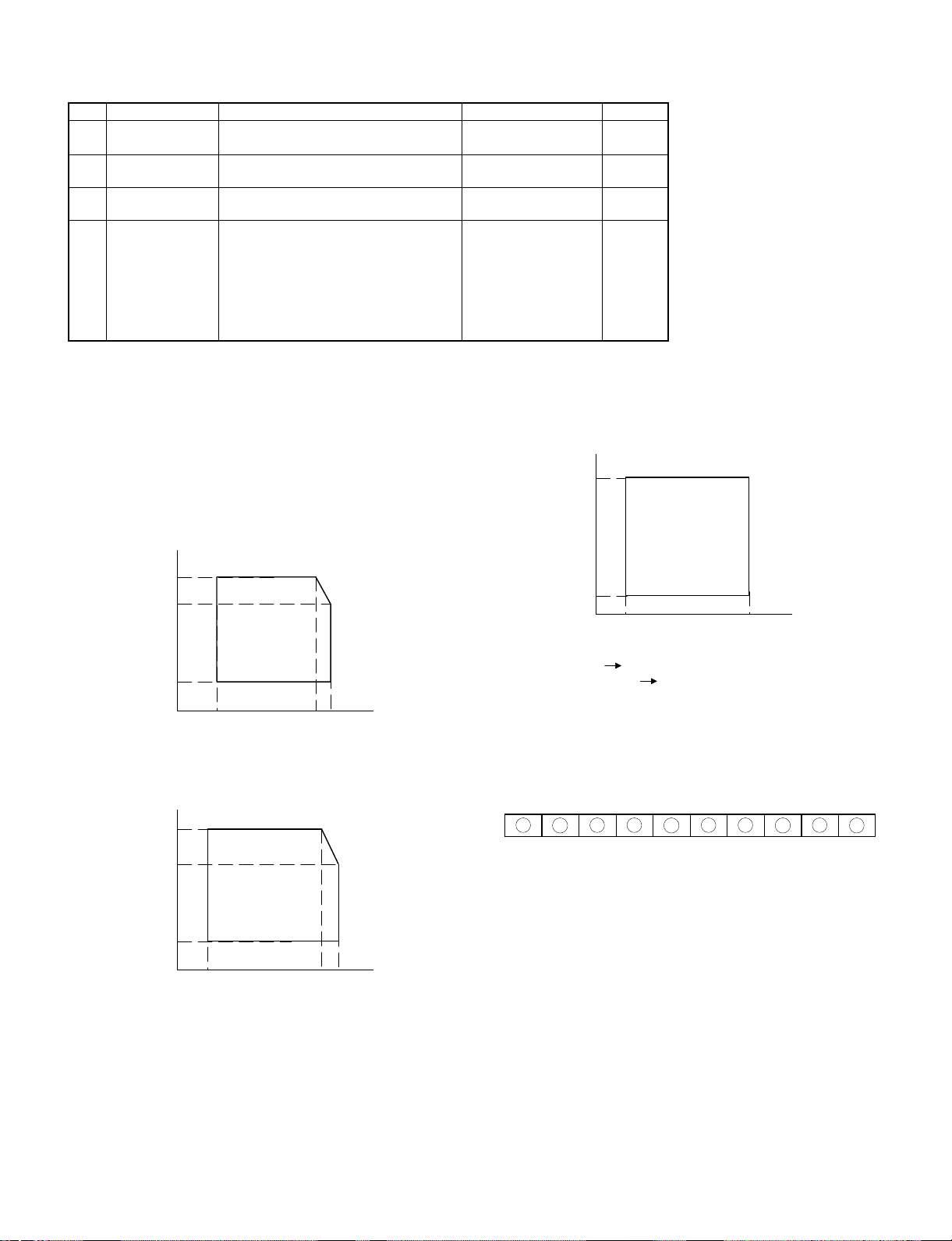
Zooming range
(64 ~ 129%)
Single manual feed (Standard)
250-sheet tray
50
50-sheet multi manual feed unit (SF-MF14)
(Option)
1 – 1
Page 5
[2] PRODUCT SPECIFICATIONS
1. Basic specifica tio ns
(1) Type: Table top
(2) Copy speed
Paper size Normal Enlargement Reduction
B4 11 sheets/min 10 sheets/min 12 sheets/min
A4 (Landscape) 14 sheets/min 10 sheets/min 12 sheets/min
B5 (Landscape) 14 sheets/min 10 sheets/min 12 sheets/min
10″ × 14″ 11 sheets/min 10 sheets/min 12 sheets/min
Legal 11 sheets/min 10 sheets/min 12 sheets/min
Letter
(Landscape)
Note: Copy speeds in the enlargement/reduction copy are the
same in all the rates.
(3) Warm-up time
Normal 30 sec or less (20 °C, 65%RH, rated
(Preheat YES/NO) 10sec or less (Preheat mode)
Jam recovery time 8sec (Conditions: Standard condition
(4) First copy time
First copy time from
each paper feed port
(5) Jam recovery time: 5 sec (Condition: Jam in a section except
(6) Multi copy
Max. quantity of multi copy 99 sheets
(7) Original
Max. original size B4/10″ × 14″
Original reference
position
Detection NO
Detection size AB series
14 sheets/min 10 sheets/min 12 sheets/min
voltage)
Max. 30sec (auto power shut off mode)
after 60sec of leaving after opening
the door.)
Tray: 5.9sec
Manual: 5.9sec
for the fuser section, within 6.0 sec from
door open, standard condition.)
Left side, about 12mm from the rear
Inch series
(10) Void width
Normal Reduction Enlargement
Lead edge
3.0mm or less
Void area
Image
loss
(11) Paper exit
Paper exit tray capacity 100 sheets
(12) External view
W × D × H (mm) OC top 500 × 492 × 288
Occupying area W (mm) 500 + 257 (paper exit tray) +
Weight About 27.4 kg
(13) Power source
Voltage 100V, 110V, 120V, 127V, 220V, 220 ∼ 230V,
Frequency 50/60Hz common
(14) Power consumption
Max. power consumption 1.4 kW
Average power consumption when operating
(Ref. value)
Power consumption in standby (Ref. value) 72.5 Wh
Power consumption in pre-heating (Ref. value) 47.7 Wh
Power consumption in auto power shut off
(Ref. value)
Auto OFF mode (Ref. value)
Dry heater connected
Dry heater not connected
Energy consumption efficiency 49.4 Wh
Note: Max. value when an option is installed.
Side (front)
3.0mm or less
Rear edge
1mm ∼ 3.0mm
Lead edge
3.0mm max.
Side (front)
3.0mm max.
Rear edge
4.0mm max.
D (mm) 492
230 ∼ 240V, 240V
Lead edge
3.0mm or less
Side (front)
3.0mm or less
Rear edge
1mm ∼ 3.0mm
Lead edge
5.0mm max.
Side (front)
5.0mm max.
Rear edge
6.0mm max.
205 (option Multi paper feed
unit)
Lead edge
3.0mm or less
Side (front)
3.0mm or less
Rear edge
1mm ∼ 3.0mm
Lead edge
2.5mm max.
Side (front)
2.5mm max.
Rear edge
3.0mm max.
582.4 Wh
14.8 Wh
9.5 Wh
0 Wh
(8) Copy magnification ratio
Fixed
ratio
(9) Exposure
AB series 3R+3E/129, 122, 115, 81, 70, 64%
Inch series 2R+2E/129, 117, 78, 64%
Zoom width 64 ∼ 129%
Exposure mode Auto/Manual/Photo
Manual steps 9 steps
2. Details of each section
(1) Paper feed
Copying size
(Max. ∼ Min.)
Paper feed system 1 tray + single manual feed
Paper feed capacity 250 sheets × 1
2 – 1
AB series B4 ∼ A6 (Postcard)
Inch series 10 × 14 ∼ 5 1/2 × 8 1/2
Page 6
• AB series
Each paper
feed port
Tray B4 ∼ A5
Single
manual feed
Paper feed
size
(Landscape)
B4 ∼ A6
postcard
(Portrait)
*For paper of 104 ∼
130g/m2, A4 or smaller.
Multi
manual
feed (OP)
• When in
multi
paper
feed
• When in
single
paper
feed
B4 ∼ A5
(Landscape)
B4 ∼ A6 52 ∼
*For paper of 104 ∼
130g/m2, A4 or smaller.
• Inch series
Each paper
feed port
Tray 10 × 14 ∼
Single
manual feed
Paper feed
size
5 1/2 × 8
1/2
10 × 14 ∼
5 1/2 × 8
1/2
*For paper of 28 ∼
34.5lbs, letter size or
smaller.
Multi
manual
feed (OP)
• When in
multi
paper
feed
• When in
single
paper
feed
10 × 14 ∼
5 1/2 × 8
1/2
10 × 14 ∼
5 1/2 × 8
1/2
*For paper of 28 ∼
34.5lbs, letter size or
smaller.
Paper
weight
56 ∼
80g/m
52 ∼
130g/m
56 ∼
80g/m
130g/m
Paper
weight
15 ∼ 21 lbs. Recommended
14 ∼ 34.5
lbs.
15 ∼ 21 lbs. Recommended
14 ∼ 34.5
lbs.
2
2
2
2
Special paper
Recommended
recycle paper
No. 2 original,
OPH, label,
recommended
recycle paper,
postcards
Recommended
recycle paper
Recommended
recycle paper,
No. 2 original,
OPH label
Special paper
recycle paper
No. 2 original,
OHP.
recommended
recycle paper
recycle paper
No. 2 original,
OHP, label,
recommended
recycle paper
Paper
feed
position
Front
Side
Side
Side
Paper
feed
position
Front
Side
Side
Side
(2) Optical section
Light source Halogen lamp
Exposure system Slit exposure by moving the
light source
Magnification ratio changing
system
Lens Fixed focus lens
(3) Process section
Charging system (–) DC scorotron system
Transfer system (–) DC scorotron system
Separation
system
Copy mode
Main charger
grid voltage
Charge/Transfer
charger applied
voltage
(4) Developer section
Developing system Two-component developing
Toner density detection
system
Toner box capacity Toner 210 ±5g
Developing bias DC–200V±3V
Standard 8-02 –750V
Photo 8-03 –460V
Toner save 8-04 –634V
By changing the lens
position and scan speed.
Discharge plate/separation pawl
Simulations
No.
–50.0µA ± 4µA
system
Magnetic sensor system
• Developer
Material Iron powder carrier
Charging system Negatively charged by friction
• Toner
Charging system Positively charged by friction
(5) Fuser section
Fusing system Heat roller system
Upper heat roller surface
temperature
Heater lamp 100V Halogen lamp 1000 W × 1 pc.
110V Halogen lamp 1000 W × 1 pc.
120V Halogen lamp 1000 W × 1 pc.
127V Halogen lamp 1000 W × 1 pc.
220V Halogen lamp 1000 W × 1 pc.
230V Halogen lamp 1000 W × 1 pc.
240V Halogen lamp 1000 W × 1 pc.
180°C
Grid
voltage
(6) Drive section
2 – 2
Main motor
standard
3-phase full wave drive, DC brushless
Rating: DC32V, max. 1.32A, 1500 rpm
Page 7
3. Supplies
Middle and South America
No. Name Content Product name Life
1 OPC drum kit
2 Black developer
3 Black toner
4 Heat roller kit
Note 1: The heat roller kit for this series is common with the previous
models SF-2314/2414/2514.
OPC drum x 1
Cleaning blade x 1
SF114DR 50K
Black developer (560g) x 10 SF114LD
(SF114DVx10)
Black toner cartridge (200g) x 10 SF114LT
(SF114Tx10)
Upper heat roller x 1
Upper fusing separation pawl x 3
Fusing bearing (F) x 1
Fusing bearing (R) x 1
SF214HR
(For LAG: SF214HR1)
Roller stopper x 2
Lower heat roller x 1
Lower fusing separation pawl x 4
60K × 10
6K × 10
80K
Environmental conditions
Observe the following environmental conditions to ensure the copy
quality and machine performance.
1 Standard condition
20 ∼ 25 °C, 65 ±5% RH
2 Operational condition
(%)RH
85
60
20
10 30 35
(˚C)
3 Shipping condition of copier (within 2 weeks)
(%)RH
90
4 Supply storing condition
(%)RH
90
10
-5
Storage peri od:
OPC drum Max. 36 mont hs fr om product i on
Developer /T oner Max. 24 mon ths fr om pro duct ion
40
(˚C)
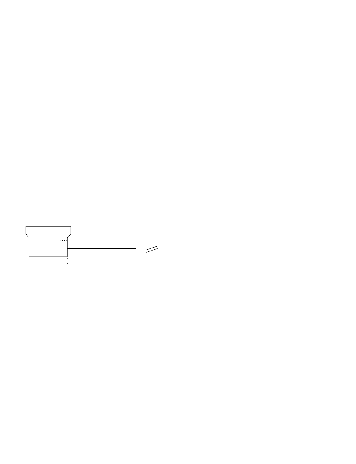
5 Identification of production number
A. OPC drum
The lot no. is of 10 digits. Each digit indicates as follows. This number
is printed on the F side flange.
1 2 3
4
5
6
7 8
9
10
60
20
-20 30 45
(˚C)
1 Numeral
Indicates the OPC drum sensitivity.
2 Alphabet
Indicates the model code. "M" is the code for this model.
3 Numeral
The end digit of the year of coating.
4 Numeral or X, Y, Z
Indicates the month of coating.
X means October, Y November, and Z December.
56 Numeral
Indicates the day of coating.
7 Numeral or X, Y, Z
Indicates the month of packing.
X means October, Y November, and Z December.
89 Numeral
Indicates the day of packing.
2 – 3
Page 8

F Alphabet
Indicates the factory of production. "A" is the code for Nara plant.
B. Developer and toner
The lot number of toner is put on the individual cartridge package and
on the group package, and that of toner is put on the bag and the
group package.
The lot number is of 7 digits, each digit indicating as follows:
1
2 3
4 5 6
7
1 Alphabet
Indicates the factory of production.
2 Numeral
Indicates the end digit of the year of production.
34 Numeral
Indicates the month of production.
56 Numeral
Indicates the day of production.
7 Numeral
Indicates the sub lot number.
Normal C A B
1234
When a change is made on the product in the same operation system:
Normal C A B
15263748
A,B,C: Operation system
2 – 4
Page 9
[3] EXTERNAL VIEW AND INTERNAL STRUCTURE
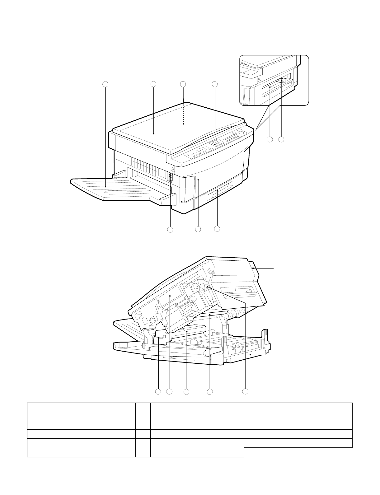
1. External view and intern al str uctu r e
1 2
3
7
4
5
6
8
9
Upper un i t
Lower unit
11
10
No. Name No. Name No. Name
Exit tray
1
Operation panel
4
Power switch
7
Fusing unit lever
F
Photoconductive drum
I
Document cover
2
Manual bypass
5
Front cover
8
Toner cartridge
G
Release lever
J
12
13 14
Document glass
3
Manual bypass guide
6
Paper tray
9
Fusing unit
H
3 – 1
Page 10
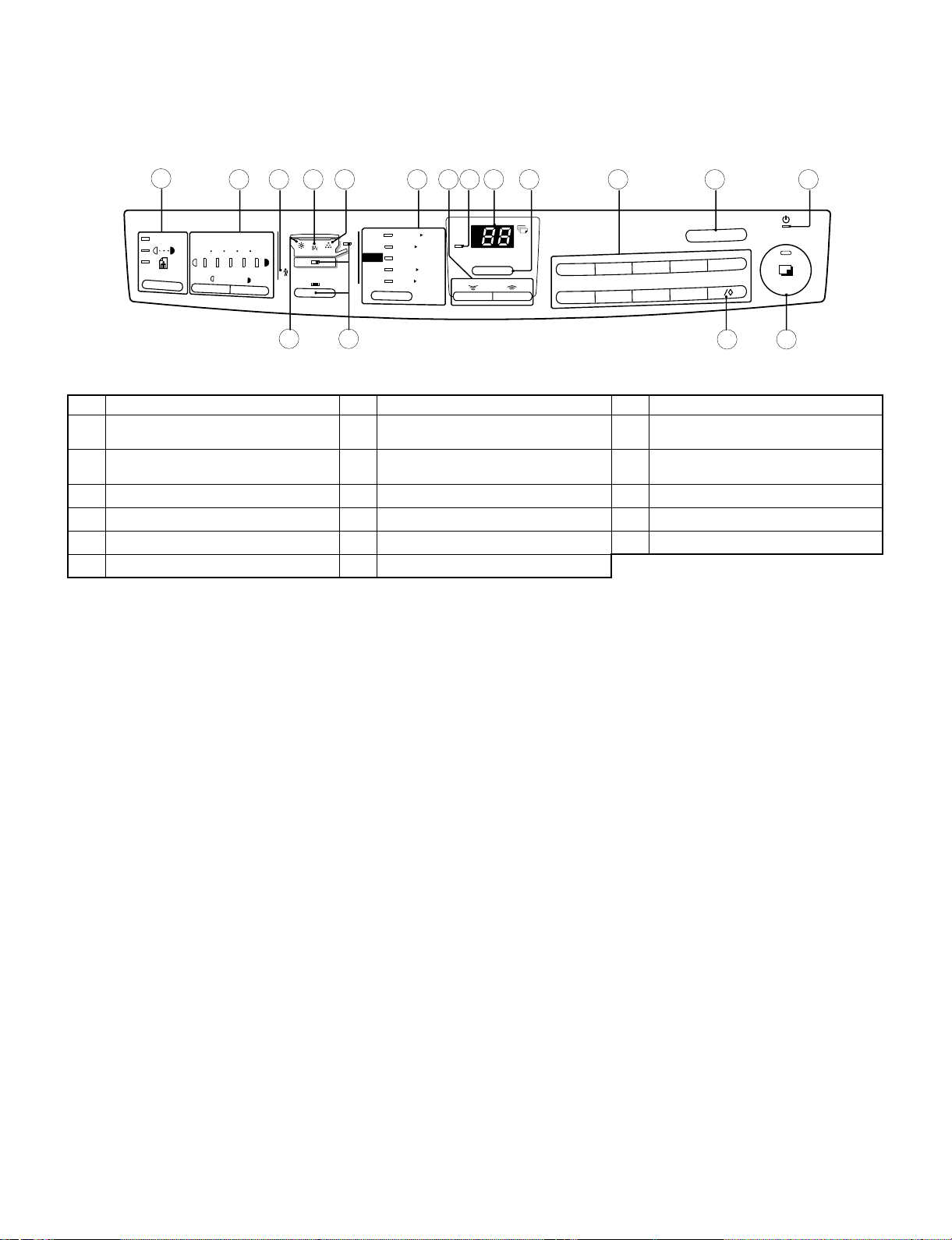
2. Operation panel
SF-1014
1
AUTO
2 3 5 6 7 8 9 10 11 12 13 14
1/2x11
1/2x81/2
5
129%
1/2x11 10x14
8
15
117%
100%
1/2x14
78%
8
1/2x1151/2x 1/2
88
64%
51234
4
8
1/2x11
8
ZOOM
%
1
6
3
2
8
7
C
5
4
0
9
No. Name No. Name No Name
Auto/manual/photo key and indicators
1
Developer replacement required
4
indicator
Copy ratio selector key and indicators
7
Copy quantity display
F
Clear key
I
Zero/readout key
L
Light and dark keys and exposure
2
indicators
Misfeed indicator
5
Zoom keys
8
Copy ratio display key
G
Power save indicator
J
Print button and READY indicator
M
Maintenance required indicator
3
Toner required indicator
6
ZOOM indicator
9
10-key pad
H
Tray select key and indicators
K
1716
3 – 2
Page 11
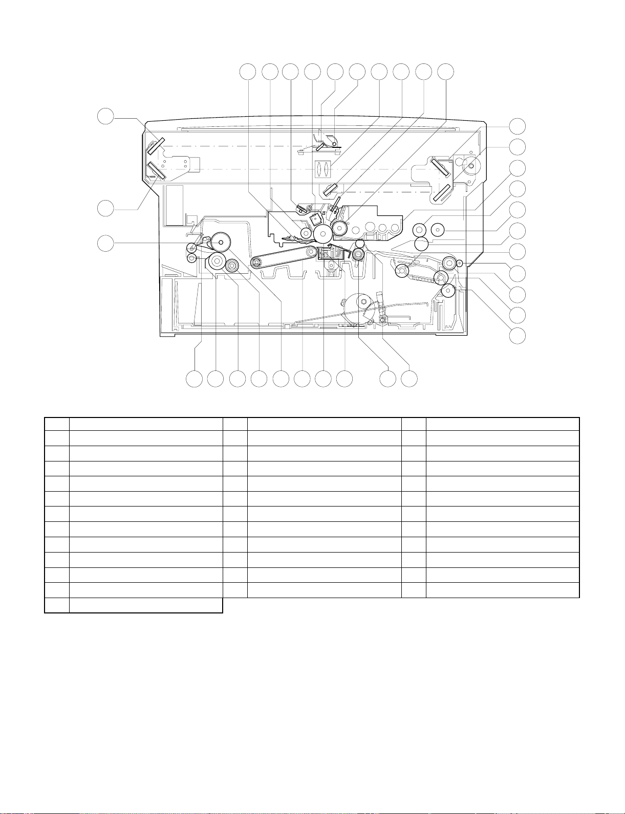
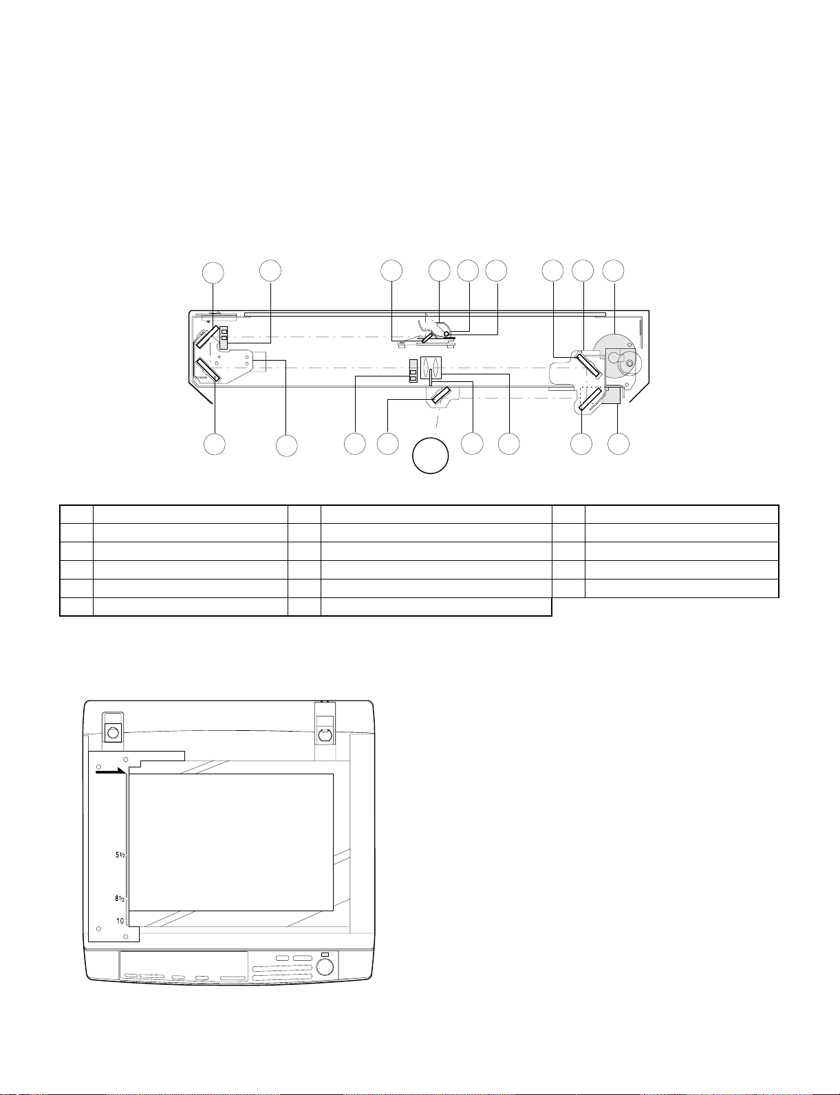
3. Cross section
34
3
51098
4
7
6
11 12
2
13
14
15
16
1
17
18
19
20
21
22
23
31
32
33
No. Name No. Name No Name
No.3 mirror
1
Cleaner unit
4
No.1 mirror
7
No.6 mirror
F
No.4 mirror
I
Manual paper feed roller
L
Tray paper feed takeup roller
O
Tray paper feed roller
R
Resist roller
U
Suction belt
X
Lower heat roller
[
Heater lamp
^
30
No.2 mirror
2
Discharge lamp
5
Copy lamp
8
Blank lamp
G
No.5 mirror
J
Manual feed take-up roller
M
Tray transport follower roller
P
Option tray transport roller
S
Transfer charger
V
Upper heat roller
Y
Lower separation pawl
\
2829
2627
25
24
Drum separation pawl
3
Main charger unit
6
Lens unit
9
Developer magnet roller
H
Developer tank
K
Manual paper feed follower roller
N
Transport roller (Upper)
Q
Resist roller
T
Photoconductor drum
W
Lower cleaning roller
Z
Upper separation pawl
]
3 – 3
Page 12
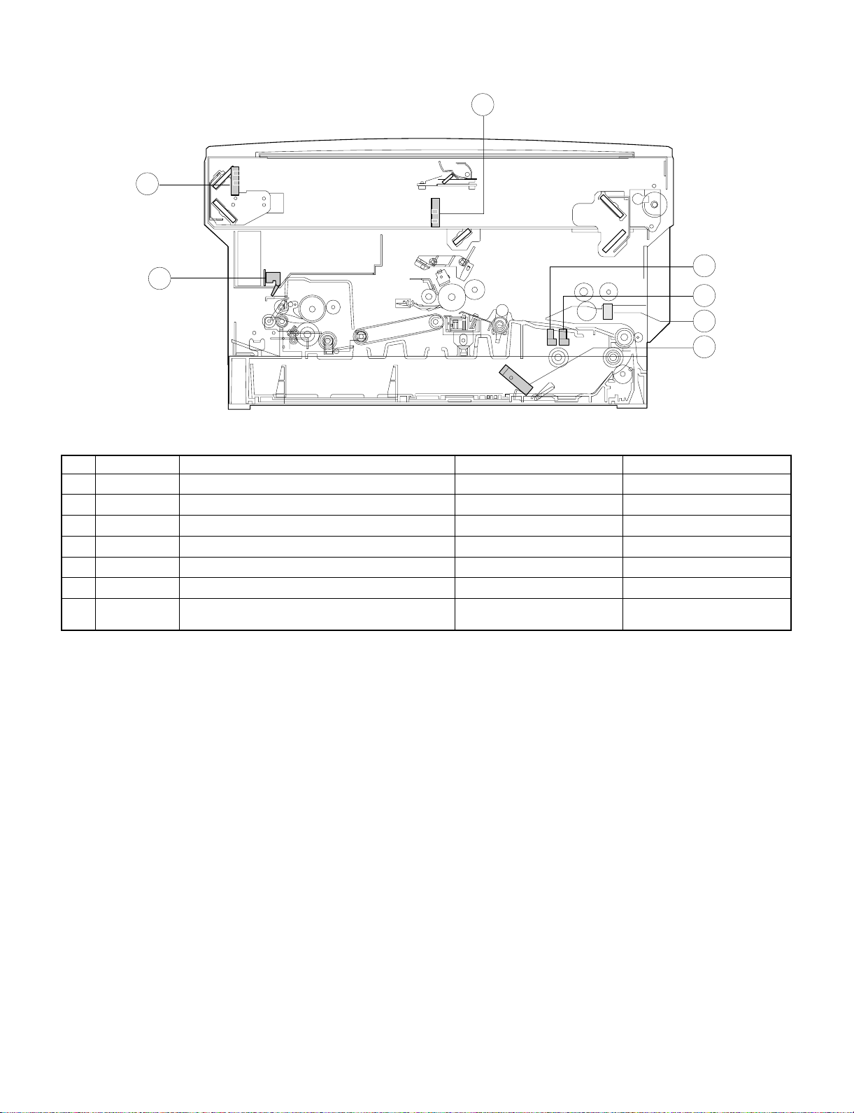
4. Switches, sensors, detectors
2
3
1
5
4
7
6
No. Abbreviation Function Type Operation
POD Paper out sensor Transmission photo sensor H when paper is sensed.
1
MHPS Mirror home position sensor Transmission photo sensor H at the home position.
2
LHPD Lens home position sensor Transmission photo sensor H at the home position.
3
PWD Paper size (large/small) sensor Transmission photo sensor L with the large size.
4
PPD Paper transport sensor Transmission photo sensor L when paper is sensed.
5
CPED1 Tray paper empty sensor Transmission photo sensor H when paper is present.
6
7
PID (MFD1)
Paper sensor for Manual paper feed unit
(only single Manual Paper feed unit)
Transmission photo sensor L when the cover is open.
3 – 4
Page 13
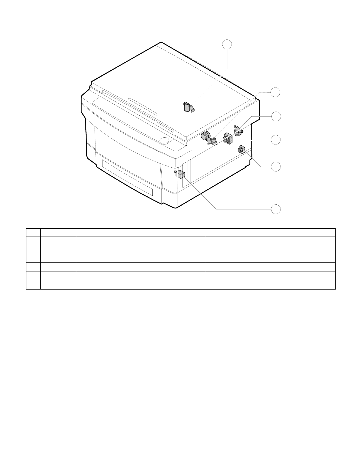
5. Clutches, sol eno id s
1
2
6
3
5
4
No. Abbreviation Name Function and operation
PSPS Paper separation solenoid For paper separation solenoid drive
1
RRC Resist roller clutch For resist roller rotation
2
TRC Transport roller clutch For transport roller rotation
3
MPFS Manual paper feed solenoid For takeup roller pressing
4
CPFC1 Tray paper feed clutch For paper feed roller rotation
5
MPFC Multi paper feed clutch For multi paper feed roller rotation
6
3 – 5
Page 14
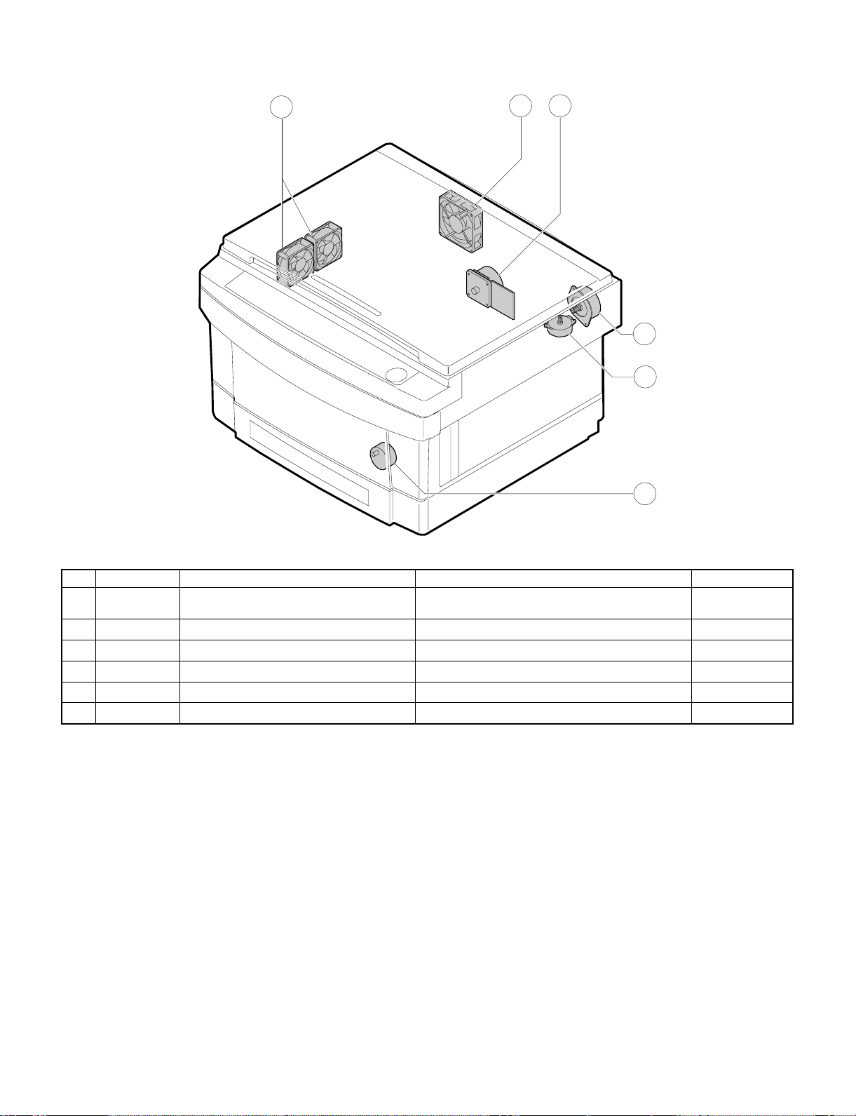
6. Motors
3
1
2
5
4
6
No. Abbreviation Name Function Type
VFM Paper exit fan motor
1
CFM Cooling fan motor For cooling the optical system DC brushless
2
MM Main motor For the main body drive and the option drive DC brushless
3
LM Lens motor For the optical lens drive DC stepping
4
MRM Mirror motor For the optical mirror base drive DC brushless
5
TM Toner motor For toner supply DC synchronous
6
For ventilation of the fuser unit.
For cooling the machine and removing ozone.
DC brushless
3 – 6
Page 15
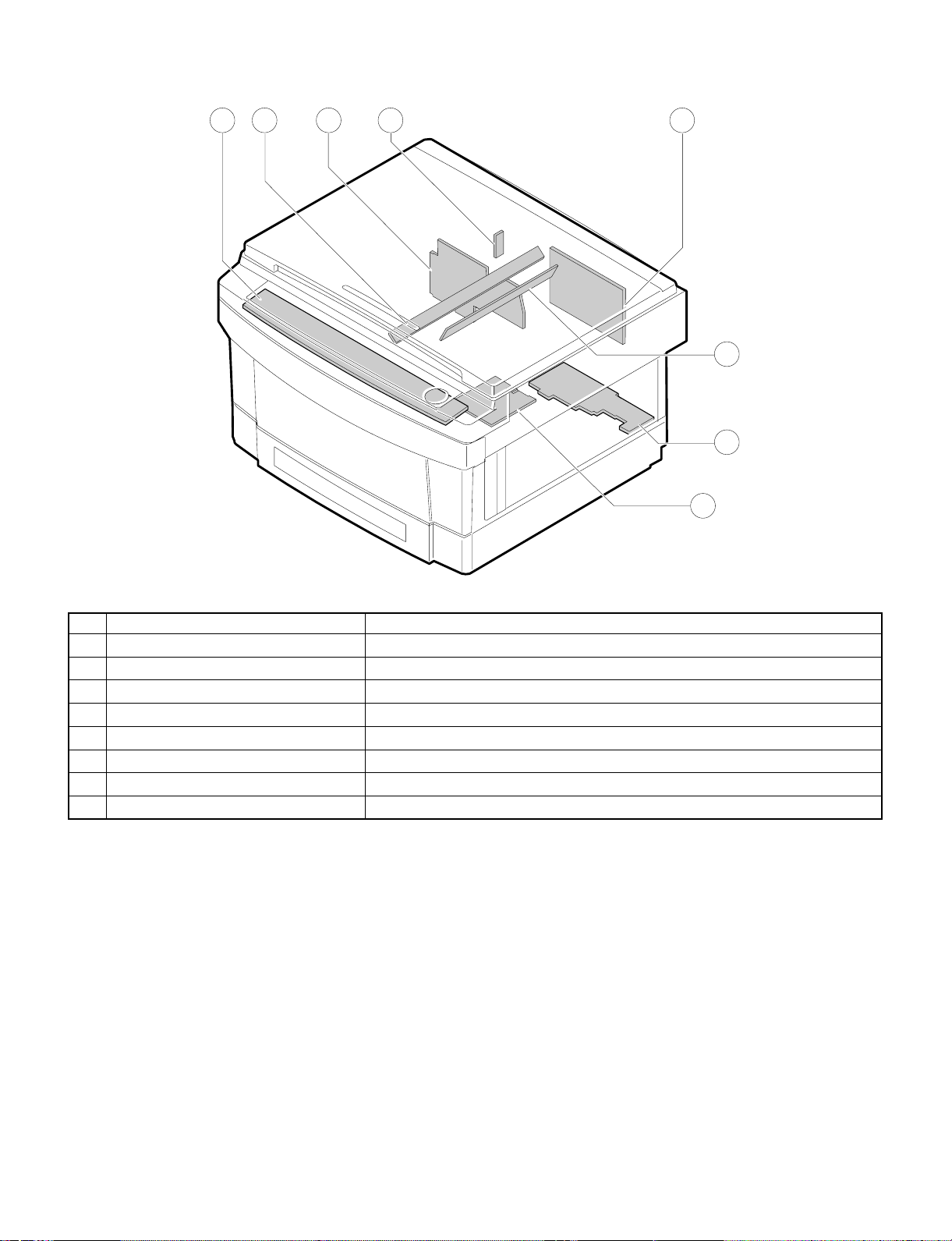
7. PWBs
8
2 1
4
3
5
6
7
No. Name Description
AC circuit PWB AC power input
1
Discharge lamp PWB Discharge lamp drive
2
Main PWB Main body control
3
AE PWB Document density auto exposure detection
4
Blank lamp PWB Blank lamp control
5
Lower unit PWB Lower unit parts control
6
High voltage PWB Supply of the process high voltage and the developer bias voltage.
7
Operation PWB Operation input, display control
8
3 – 7
Page 16
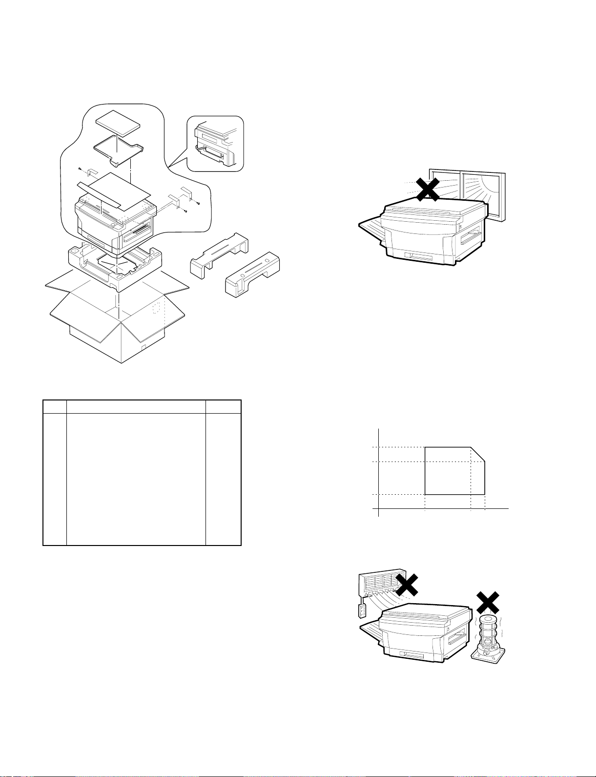
[4] UNP ACKING AND INSTALLAT ION
1. Packing drawi ng
List of packing materials and accessories
Name Q’ty
1 Packing case 1
2 Body 1
3 Polyethylene bag for paper exit tray 1
4 Vinyl sheet for body 1
5 Bottom case 1
6 Bottom case pad (L) 1
7 Bottom case pad (R) 1
8 AC cord sleeve 1
9 Paper exit tray 1
10 Instruction Manual 1
2. Installat ion
Installation conditions
The following installing conditions must be satisfied to assure the
normal operations of the machine.
(1) Environment
1 Keep the machine away from direct sunlight and avoid instal-
lation near a window or in a bright place.
(Draw the curtain and close the blind shutter completely.)
The plastic parts and the original cover may be deformed by direct
sunlight. Avoid installation near a window even with frosted glass.
2 Avoid installation in high temperature or high humitity en-
vironments. Also, avoid installation where temperature or
humidity may change quickly. (e.g., near an air conditioner).
Otherwise copy papers may be dampened and condensation may
be generated in the machine. This may result in paper jams or
poor copy quality.
(Ideal conditions): The best suitable conditions for machine
operation:
20°C ∼ 25°C: 65 ±5%RH
(Temperature/humidity range): 15°C ∼ 30°C (59°F ∼ 86°F),
20% ∼ 85%
65% for 35°C (95°F)
% RH
85
65
Humidity
20
˚C
15 30 35
(59˚ ) (86˚ ) (95˚)
(˚F)
4 – 1
Page 17
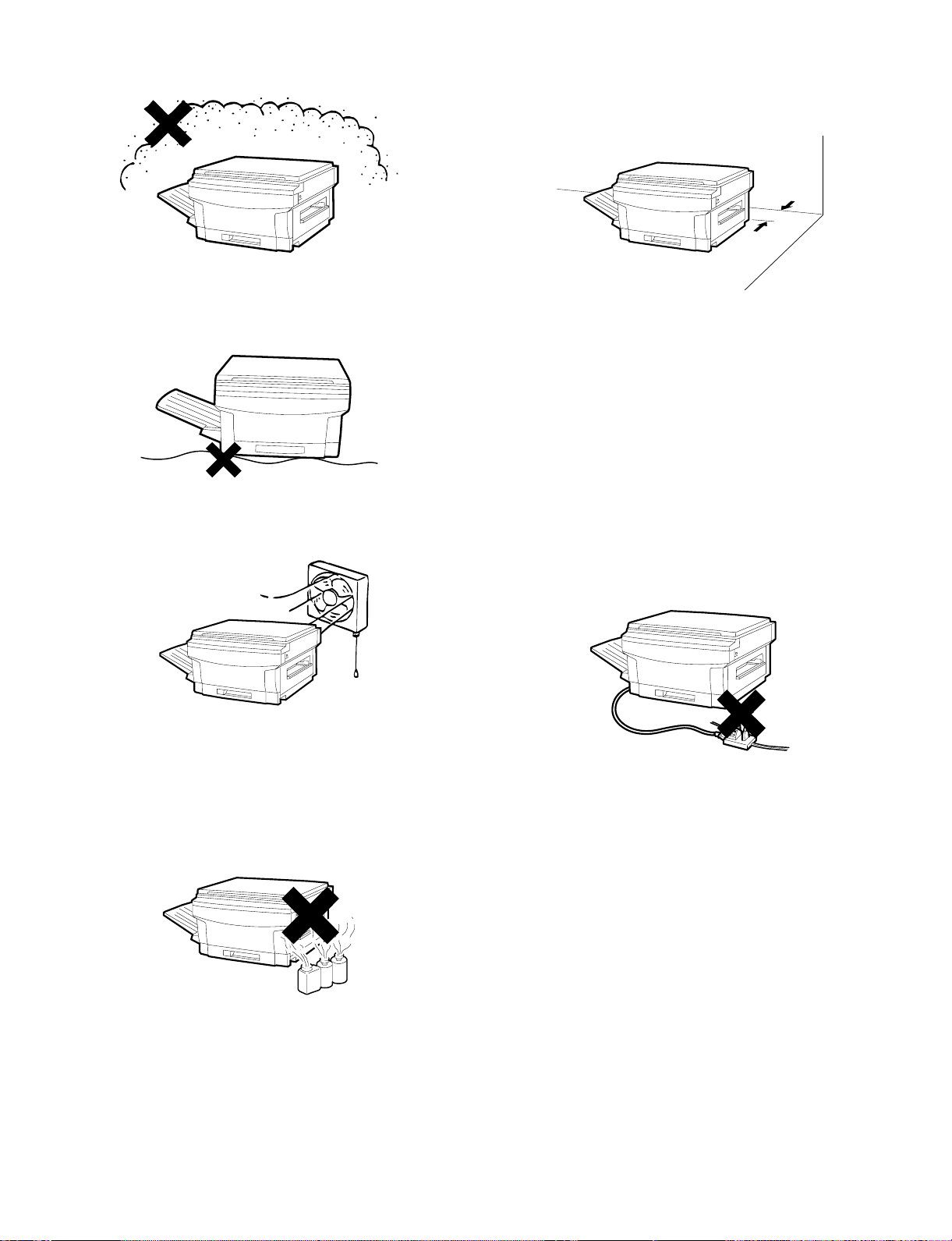
3 Avoid installation where there is a lot of dust or vibrations.
If dust enters the machine, it may degrade copy quality and cause
malfunctions.
4 Avoid installation on an unstable surface.
To assure the proper operations, install on a level surface.
5 Install in a well ventilated place.
(2) Space around the machine
Allow a space of about 15 cm (6 inches) between the rear side of the
machine and the wall for ventilation of the cooling fan. Also allow
sufficient space around the machine for operations.
(3) Installing table
Use a level (UKOGM0054CSZZ) to install the machine horizontally.
(Allowable tilt: 5 mm between the front and rear frames)
(Note) If the machine is not installed horizontally, toner density con-
trol may not function properly. This may result in poor copy
quality.
(4) Power source
1 The power source should be the rated voltage ±10% with the
capacity corresponding to the max. power consumption.
2 Do not use an extension cord, or operate any other equipment
from the same wall outlet.
6 Avoid installation where there is inflammable gases or am-
monium gases.
Installation near a diazonium copier may degrade copy quality and
cause malfunctions.
7 Install near a power outlet.
(5) Grounding
To avoid electrical hazard, use the properly grounded wall outlet only.
(Carrying the machine)
When carrying the machine, remove the copy tray and hold the dent
portions on the bottom.
4 – 2
Page 18
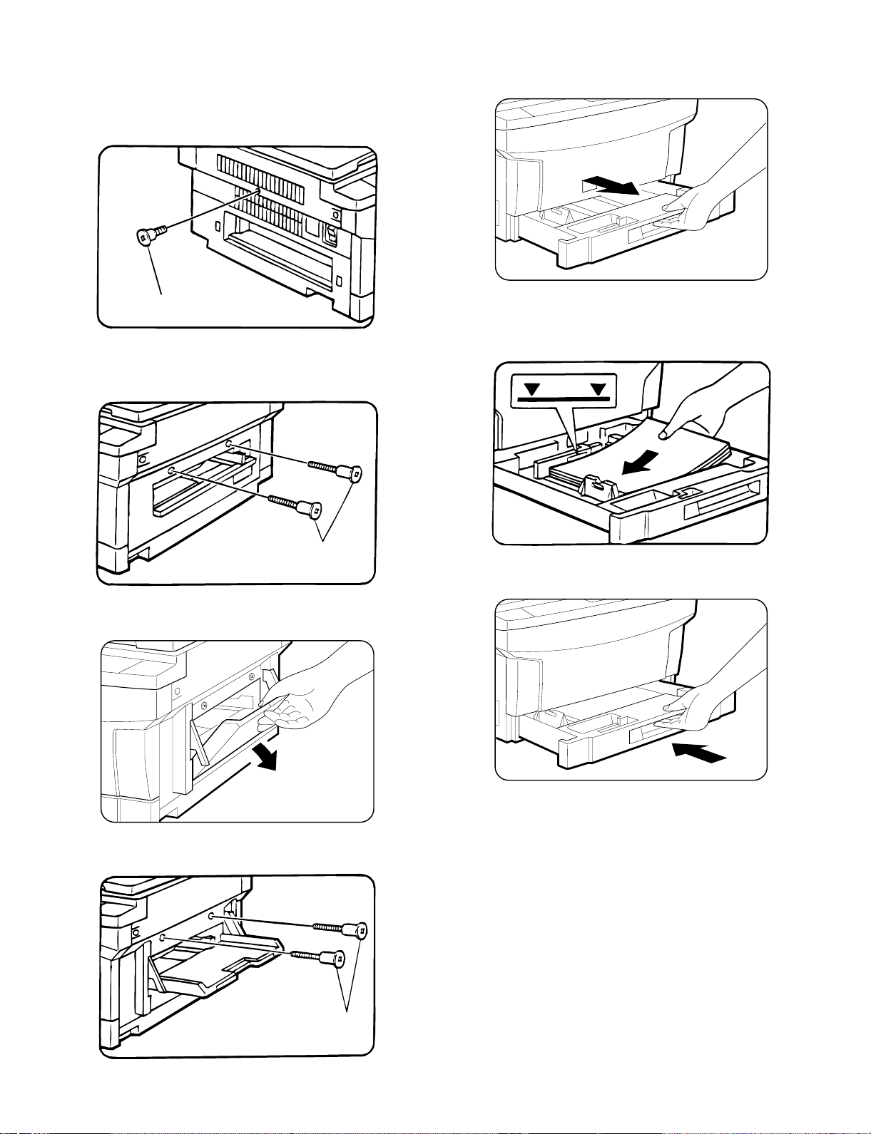
3. Installation procedure
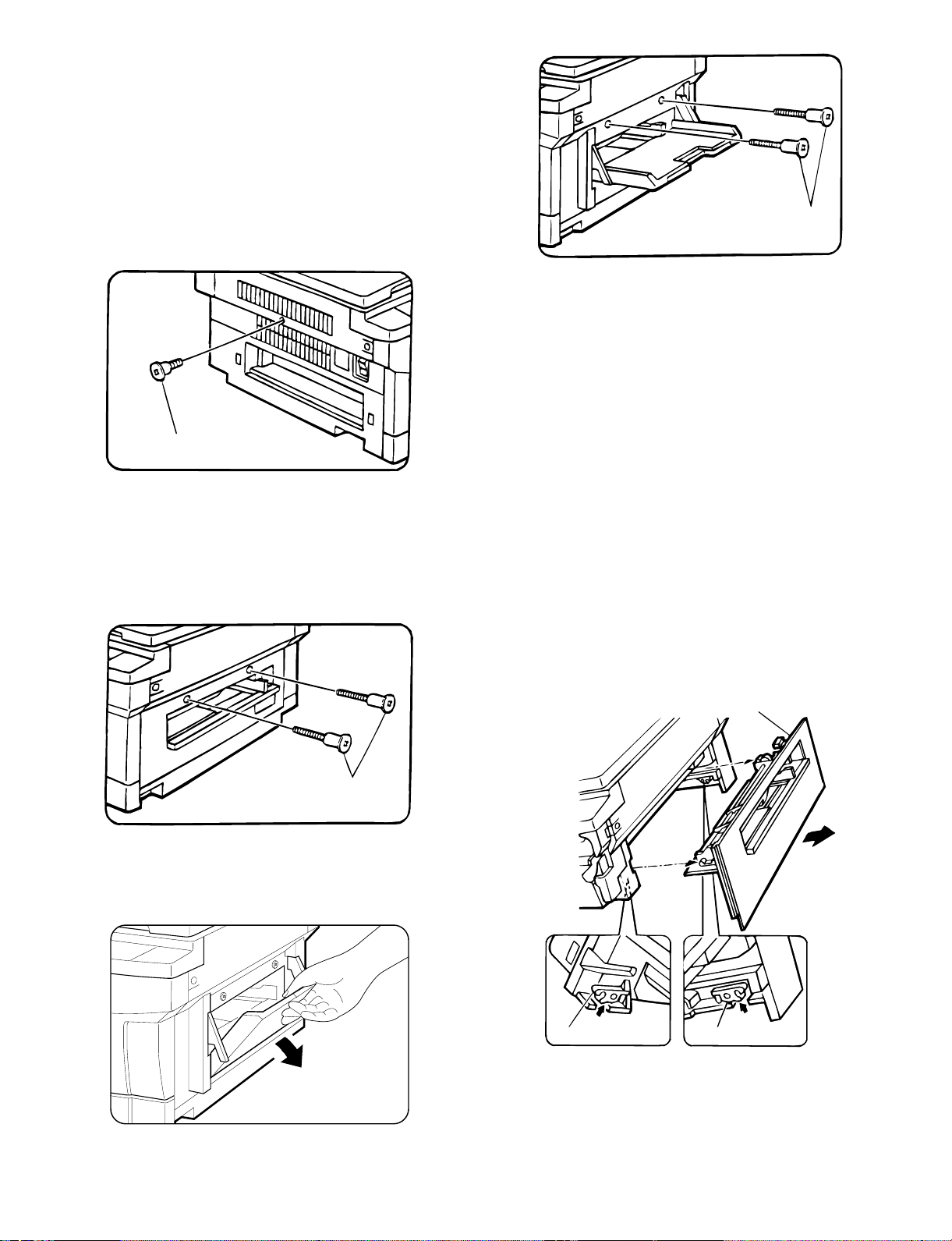
(1) Optical system unlocking
1 Unlock the No.2/No.3 mirror unit.
Remove the No.2/No.3 mirror unit fixing screw (1 pc.) on the left
side of the copier.
(2) Cassette setting
1 Pull out the cassette.
Lift the cassette and slowly pull it out from the copier until it stops.
Mirror unit fixing screw
2 Unlock the No.4/No.5 mirror unit.
Remove the No.4/No.5 mirror unit fixing screws (2 pcs.) on the
right side of the copier.
Mirror unit fixing screw
[In the case of SF-1014 with SF-MF14 (Optional) equipped.]
Open the paper feed tray on the right side of the copier.
2 Loading copy paper.
Set the copy papers in the cassette. Do not exceed the limit line
indicator.
Gently insert the cassette fully into the copier.
Remove the No.4/No.5 mirror unit fixing screws (2 pcs.).
Then close the paper feed tray.
Mirror unit fixing screw
4 – 3
Page 19

(3) Developer setting
1 Open the front cabinet.
Push the front cabinet open buttons which are on the left and right
sides of the copier, and open the front cabinet.
5 Remove the developer tank.
Slightly open the pawl which is fixing the developing unit and the
developer tank with a screw driver, and pull out the developer
tank.
Front cabinet open button
2 Open the toner cartridge.
While pressing the toner cartridge release lever (B), open the
toner cartridge.
Release lever (B)
Toner cartridge
Developing unit
Developing
tank
Pawl
6 Supply developer.
Supply a bag of developer to the developer supply port of the
developing unit.
At that time, move the bag of developer to supply developer evenly.
Developing
Developing unit
3 Remove the toner cartridge.
Slowly turn the toner cartridge clockwise to remove.
2
1
4 Remove the developing unit.
Loosen the fixing screw (step screw) which is fixing the copier and
the developing unit, and slowly pullout the developing unit and
Lenz hold Plate from the copier.
Fixing screw
(step screw)
Lenz hold plate
7 Install the developer tank.
Insert the developer tank to the developing unit along the guide of
the developing unit.
At that time, check that the developer tank is securely fixed in the
developing unit.
Developing unit
Developing tank
8 Install the developing unit.
Slowly insert the developing unit into the copier along the guide of
the copier until it stops.
Tighten the fixing screw which was removed in procedure (D), and
fix the developing unit to the copier.
Fixing screw
(step screw)
1
2
Developer unit
2
1
Developer unit
4 – 4
Page 20
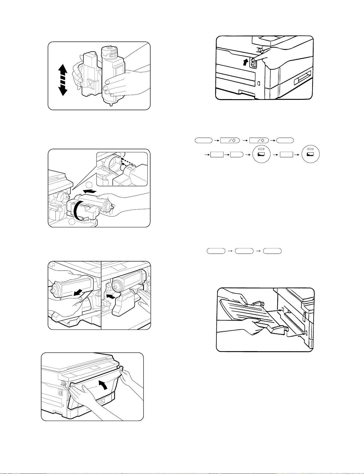
(4) Toner supply
1 Shake the toner cartridge up and down.
Shake the toner cartridge up and down 9 to 10 times.
2 Install the toner cartridge.
Install the toner cartridge to the copier along the guide of the
copier.
Turn the toner cartridge counterclockwise to lock.
(5) Toner density sensor level check
1 Turn on the power switch of the copier.
2 Adjust the developer level.
(a) Perform the key operations of simulation 25 sub 2.
C0 0 C
25 2
1
2
3 Supply toner.
Remove the sheet from the toner cartridge and supply toner.
Slowly return the toner cartridge to the original position.
4 Close the front cabinet.
With the above key operations, simulation 25 is performed and
the developer is stirred for 3 minutes.
(b) After stirring the developer for 3 minutes, the toner density
level is read by the main PWB.
During stirring, the toner density sensor level is displayed on
the MULTI COPY display. (Range: 1 ∼ 99)
[Note] If the simulation is cancelled during execution, the
automatic reading cannot be performed. Do not cancel
the simulation during execution.
(c) Press the CLEAR key three times to cancel simulation 25.
c c c
(6) Accessory attachment
Attach the copy tray.
4 – 5
Page 21
4. Locking procedure for transit or
repacking
In general, reverse the procedures in "3. Installation procedure." For
the optical system lock, perform the following procedure.
(1) No.2/No.3 mirror unit (Mirror base B) lock
1 Perform locking with the unit at its home position (normal copy
position) with the power ON and with the mirror stopped and with
the external covers installed.
2 Lock the unit with the mirror unit fixing screw. (The hole in the left
cabinet)
Mirror unit fixing screw
(2) No.4/no.5 mirror unit (Mirror base C) lock
1 Turn off the power at the 64% position. Perform locking with the
external fitting installed.
2 Open the paper feed tray at the right side of the body, and fix the
unit with two fixing screws. (Two holes in the right cabinet)
Mirror unit fixing screw
2 Open the paper feed tray at the right side of the body, and fix the
unit with two fixing screws. (Two holes in the right cabinet)
5. Optional multi bypass feeder unit
Installation Manual
(1) Open the upper unit of the main copier unit.
1 Press the release buttons on the left and right sides of the main
copier unit’s front cover, then open the front cover.
2 Push the upper half release lever (green) to the right and down,
then gently open the upper unit.
(2) Release the lock for the manual bypass unit and
remove the manual bypass unit.
1 Release the manual bypass unit by pressing upward on the rock
claws (green; 2 locations) which lock it in place in the main copier
unit’s upper unit.
The manual bypass unit will come out toward you slighly.
2 Pull out upon the manual bypass unit to remove it from the main
copier unit.
Mirror unit fixing screw
[SF-1014 with SF-MF14 (Optional) equipped.]
1 Turn off the power at the 64% position. Perform locking with the
external fitting installed.
Rock claw (latch)
Manual bypass unit
Rock claw (latch)
4 – 6
Page 22
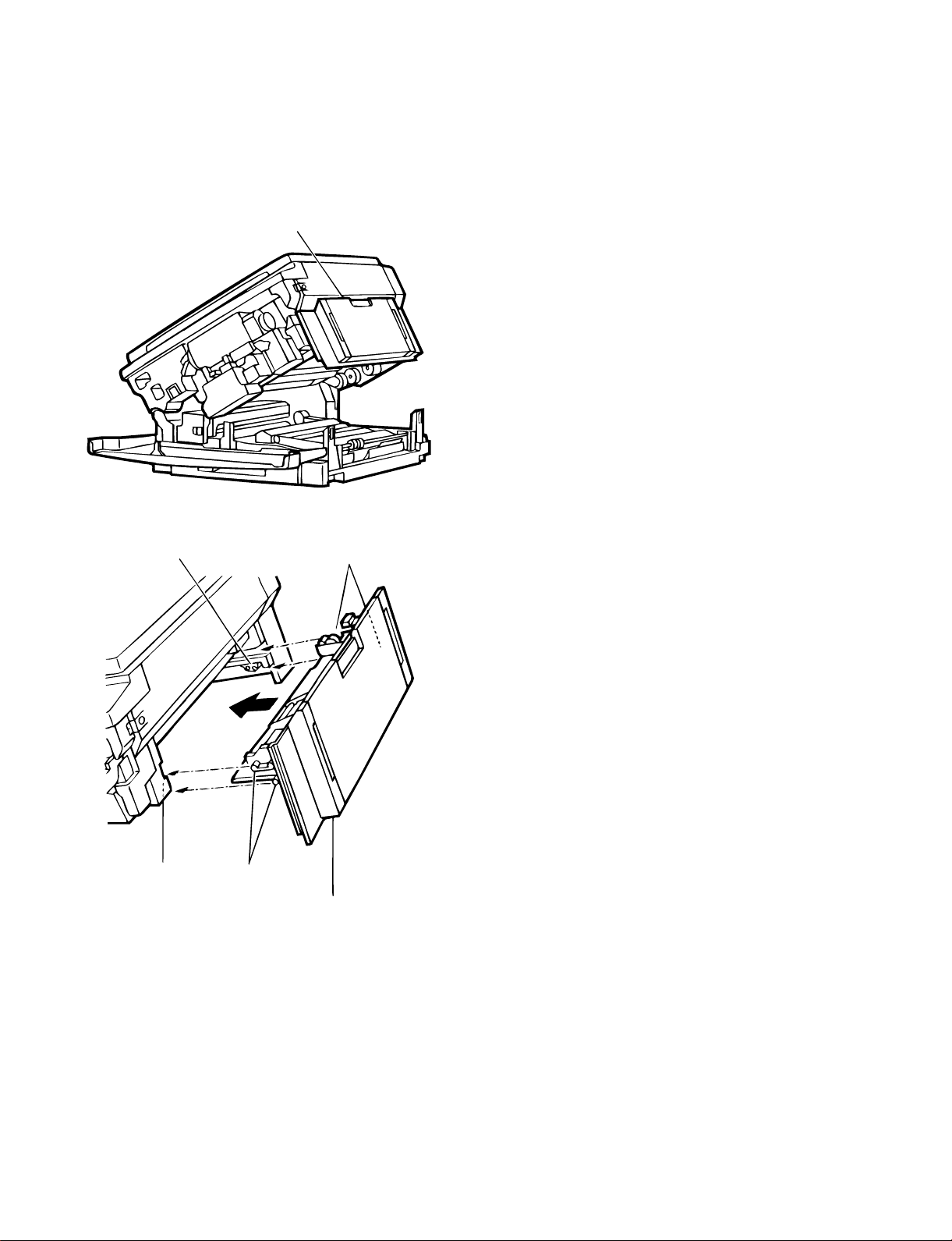
(3) Mount the multi bypass feeder unit onto the
main copier unit.
1 Slide the positioning pins which project from the multi bypass
feeder unit in to the grooves in the main copier unit, then push the
multi bypass feeder unit into place to in stall it.
At this time, to be sure that the multi bypass feeder unit is securely
installed, push down once more on the fourcorners of the unit. (If it
has not been securely installed, "CH" may appear in the COPIES
MADE display when the power is turned on.)
Multi bypass feeder unit
Rock claw (latch)
Rock claw
(latch)
2 Close the upper unit of the main copier unit.
Positioning pins
Positioning pins
Multi bypass
feeder unit
4 – 7
Page 23
[5] GENERAL DESCRIPTIONS OF
EACH SECTION
The general descriptions of the following sections are given:
1 Paper feed section
2 Separation, transport section
3 Fuser, paper exit section
4 Developer section
5 Optical system
6 Image forming section
Internal structure
5
3
6
2
4
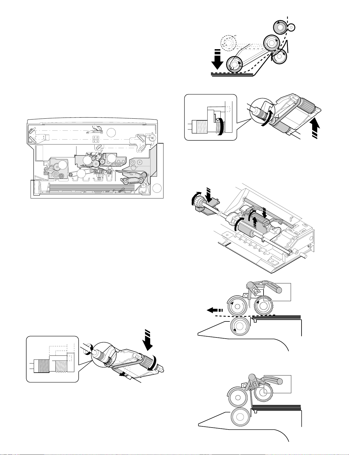
When the CPCF turns off, rotation is stopped, and the takeup roller is
pushed up by the roller release arm spring to the position.
(Manual paper feed operation) Multi
When the solenoid B (MPFS) turns on, the takeup roller falls and the
gate rises.
Almost simultaneously the solenoid A (MPFC) turns on and the
takeup roller and the paper feed roller turns to perform the paper feed
operation.
1
1. Paper feed secti on
The paper feed system is in two ways: the tray feed and the manual
feed. The cassette is of the universal type and has the capacity of
250 sheets. It is attached and detached at the front cabinet, that is,
the front loading system.
The manual paper feed is single for the this model. (The multi paper
feed unit (SF-MF14) is an option.)
(Tray paper feed operation)
The cassette paper feed clutch (CPFC) turns on, the paper feed roller
shaft, the paper feed roller, and the takeup roller rotate. At the same
time, the roller release arm is lowered by the limiter spring. As a
result, the takeup roller falls by its own weight to reach the paper
surface, performing the paper feed operation.
ON
When the PPD turns on, the MPFS turns off and the RRC turns on.
Almost simultaneously the MPFC turns off to return the roller and the
gate to the initial state.
OFF
5 – 1
Page 24
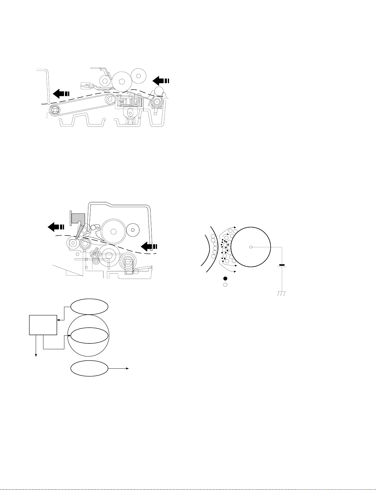
2. Separation, transport section
4. Developer section
After passing the resist roller section, the paper is transported to the
transfer section. After transfer, the paper is separated from the drum
by the separation electrode and the drum separation pawl, then
transported to the fuser section by the transport belt.
3. Fuser, paper exit section
The toner image transferred on the paper is fused by the heat and
pressure of the upper and the lower heat rollers. After fusing, discharge static electricity on the paper with the discharge brush. Then
the paper is discharged to the copy tray.
4-1. General descriptions
(1) Two-component developer
The developer is composed of toner and carrier.
Carrier serves as a medium for attaching toner onto the electrostatic
image on the photoconductor drum.
By stirring toner and carrier, they are rubbed to be charged positive
(+) and negative (–) respectively.
Since developer will deteriorate to degrade copy quality, it should be
replaced regularly.
(2) Two-component magnetic brush development
The rotatable non-magnetic sleeve is provided over the magnet roller
and is rotated.
Carrier forms a magnetic brush on the sleeve surface by magnetic
force to attach toner onto the electrostatic image on the photoconductor drum.
(3) Developing bias
When the photoconductor is charged and exposed to light (exposure), the surface potential (voltage) of the photoconductor will not
be lost completely. (The residual potential remains.)
Toner is attracted to the photoconductor by this residual potential,
dirtying the photoconductor. As a result, a dirty copy of white background is generated.
To prevent against this, a voltage of the same polarity and higher
than the residual potential is applied to the MG roller, preventing toner
from being attached to the photoconductor surface.
• Temperature control
Heat roller surface
temperature detection
The heat roller is heated by the
heater lamp.
(When the heat roller surface
temperature is 180 C˚ or lower,
the heater lamp is actuated)
Contact open (*)
Abnormal high
tem p erature
CPU
(Heater troub l e)
Self diag di spl ay
Thermistor
Heat r olle r
Heater lamp
Thermostat
• Abnormally high temperature (H3)
• Abnormally low temperature (H4)
• Thermistor disconnection (H2)
When the thermostat contact is open, it is required to press the
*
reset button in the upper side of the thermostat. (The contact is not
reset automatically.)
Toner
Carrier
Residual potential < DV BIAS
MG roller
DV BIAS
-200V
Developing bias voltage
5 – 2
Page 25
5. Optical system
5-1. General descriptions
• The optical system is composed of the fixed focus lens and six
mirrors.
Since the fixed focus lens is employed, No.4/No. 5 mirror base is
moved as well as the lens to change the distance between the
document and the drum (OID, Original Image Distance) for reduction and enlargement.
To move the lens and No.4/No. 5 mirror unit, he stepping motor is
driven by the signal from the main control PWB to allow zooming
of 0.70 to 1.22 (inch series: 0.64 ∼ 1.29) with 1% increment. (The
SF-2314 has no zooming function, and its lens and No.4/No.5
mirror base are fixed.)
4
5
10
9
• Exposure is adjusted by changing the voltage of the copy lamp.
The copy lamp unit is provided with the AE sensor for detection of
the original density to adjust the light quantity of the copy lamp
according to the original density.
• For exposure, the slit exposure system is employed where the light
source is moved. (The original table is fixed.)
17
12
615
127
1311316
8 14
1 Copy lamp 2 Reflector 3 No. 1 mirror
4 No. 2 mirror 5 No. 3 mirror 6 Lens
7 No. 4 mirror 8 No. 5 mirror 9 No. 6 mirror
F No. 2/No. 3 mirror base unit G Copy lamp unit H No. 4/No. 5 mirror base unit
I Mirror motor J Lens/No. 4/No.5 mirror base drive motor K Lens home position sensor
L Mirror home position sensor M Auto exposure sensor
(1) Original table
The original table is fixed, and originals are set to the left frame side
as the reference.
(2) Copy lamp
100V s ystem (285W)
200V s ystem (285W)
(3) Mirror
Six mirrors are used.
No. 1 mirror is provided in the copy lamp, No. 2/3 mirrors at the
No.2/3 mirror base, No. 4/5 mirrors at the No. 4/5 mirror base. The
No.2/3 mirror base is scanned during copying. The No.4/5 mirror
base is moved to change the distance between the original and the
photoconductor during zoom copying.
(4) Lens (Fixed focus lens)
• Construction (One group 3 lenses)
• Brightness (F8)
• Focus (175mm)
(5) Lens home position sensor (LHPS)
This sensor is used to sense the lens position. The sensor output
signal serves as the basic signal to control the copy magnification
ratio.
(6) Lens base
The lens is mounted to this lens base. It is moved in the paper feed
direction in reduction copying, and in the paper exit direction in enlargement copying.
5 – 3
Page 26
(7) Lens drive shaft
This shaft is to control the optical axis of the lens in zoom copying.
The lens follows on the slide base shaft.
(8) Lens drive wire
The wire is used to drive the lens base and the 4/5 mirror base.
(9) No. 4/5 mirror base
The No. 4/5 mirror is installed to this base. It is moved in zoom
copying in order to fit the distance between the original and the
photoconductor.
(10) Mirror motor
The mirror motor is a stepping motor, and used to move the copy
lamp unit and the No. 2/3 mirror base in order to obtain the rpm
corresponding to each magnification ratio.
(11) Mirror home position sensor (MHPS)
Used to sense the home position of the copy lamp unit. This sensor is
a photo transmission type sensor.
(12) No. 2/3 mirror base
The No. 2/3 mirrors are attached to this base. The mirror base is
scanned by the mirror motor.
(13) Copy lamp unit
This is composed of No. 1 mirror, the thermal fuse, the copy lamp,
the exposure adjustment plate, and the reflector, and is scanned by
the mirror motor.
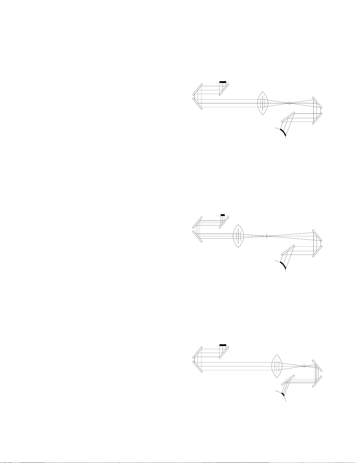
5-2. Basic operati on s
(Relationship among the original, the lens and the image in each
magnification ratio)
Normal copy: The distance between the surface of original on the
table glass and the lens is made equal to the distance
between the lens and the exposure surface of the
photoconductor to make the original and the image
equal to each other.
Enlargement copy: The lens is nearer to the original when compared
with the normal copy to shorten the distance between the original surface and the lens.
The No. 4/5 mirror base is positioned further
away from the lens to increase the distance between the lens and the exposure surface of the
photoconductor.
The distance between the original and the exposure surface of the photoconductor is greater
than that in the normal copy.
(14) Thermal fuse
The thermal fuse is closely attached to the reflector in order to
prevent against abnormal temperature rise in the optical system. In
case of abnormal temperature rise, the power for the copy lamp is
turned off.
100V system
200V system
(117°C)
(117°C)
(15) Reflector
Light from the copy lamp is reflected onto the original.
(16) Exposure adjustment plates
Four exposure adjustment plates are attached to the copy lamp unit
to adjust the exposure balance in the front and the rear frame direction.
(17) Mirror base drive wire
This wire is used to transmit the drive power of the mirror motor to the
copy lamp unit and the No. 2/3 mirror base to scan the mirror base.
(18) Lens drive motor
This is a stepping motor, which is used to move the lens and the No.
4/5 mirror base.
(19) AE sensor
The original density is detected with the intensity of the copy lamp
light reflected from the original. The measurement area is the mirror
base scan area of about 100mm at the center.
The element is a photo diode.
Reduction copy: When compared with the normal copy, the lens
comes closer to the photoconductor to increase the
distance between the original and the lens. The
distance between the lens and the exposure surface of the photoconductor is decreased.
The No. 4/5 mirror base is positioned further away
from the lens.
The distance between the original and the exposure
surface of the photoconductor is longer than that in
the normal copy.
5 – 4
Page 27
The mirror base scan speed (mirror motor rpm)
is changed t o z oom.
The lens and the mirror are
Copy paper
feed direction
The mirr or sc an speed is c hanged to zoom .
Mirror scan speed Drum rotating speed < Mirror scan speed
Enlargement
moved to zoom.
(Optical system dirt correction)
The SF-1014 perform dirt correction by changing the copy lamp intensity according to the dirt degree in the optical system (the copy lamp
unit, No. 1 mirror, No.2 mirror, No.3 mirror) to prevent against remarkable degrading of copy quality.
The reference value is the AE sensor output value which is obtained
when the reference plate is exposed with the copy lamp voltage of
67.7V (135.4V) at power ON.
This value is checked with sim 44-02.
Reference plate (Glass holder)
Table glass
Copy lamp light quantity "UP"
Original
(Copy lamp control in each copy density)
80
70
CLV
(Copy lamp
application
voltage)
60
50
40
(V)
Reduction
[MAX. 85V(170V)]
[MIN. 40V(80V)]
The lens
and the
mirror are
move to
zoom.
Automatic exposure
sensor
CPU
Reference value
> Measured value
Correction data output
EX1
234
EX5
5 – 5
Page 28
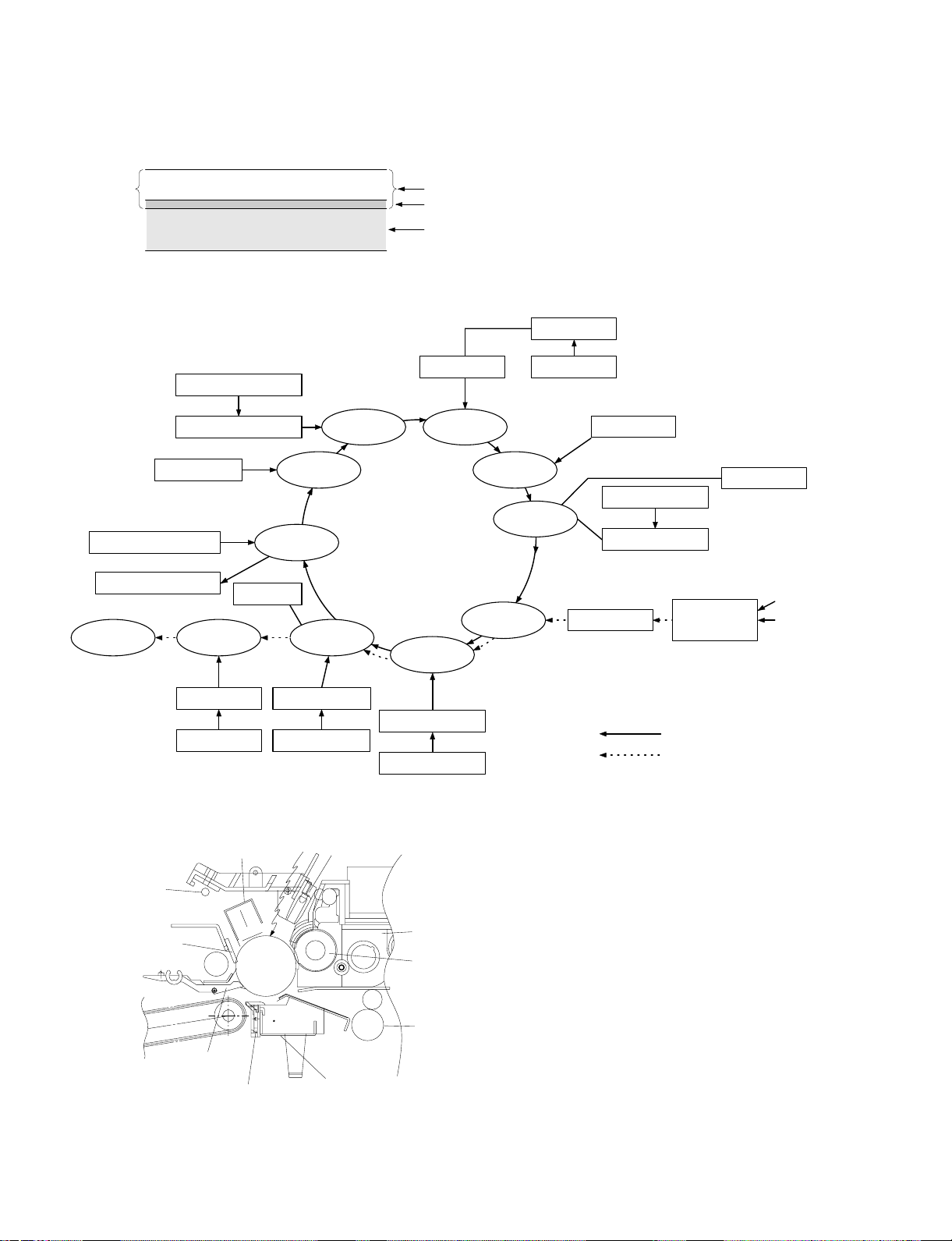
6. Copy process
(1) Photoconductor
• This model uses OPC (organic photoconductor) as photoconduc-
tive material.
OPC layer CTL (Electric charge moving layer)
CGL (Electric charge generating layer)
Aluminum layer
(2) Process diagram
Original
Copy lampMirror lens
High voltage unit
Exposure
Transfer
Exposure
Development
Drum up per
ima ge/paper
synchronization
Resist roller
Discharge lamp
Cleaning bl ade
Waste toner collection
Paper exit
Main corona unit
Separ a tion
Fusing
Charging
Discharging
Cleaning
Separation
Blank lamp
Toner
Developer
High voltage unit
Paper feed roller
Transportroller
Manual paper feed
Pape r ca sse tte
Discharge lamp
Cleaning bl ade
Seper ati on pa w l
Heat r olle r
Heater lamp
Separation cor ona unit
High voltage unit
Main corona unit
Seperation corona unit
Transfer charger
High voltage unit
Blank lamp
Devel oper u nit
MG roller
Resist roller
Transfer corona unit
Image forming process
Paper transport path
5 – 6
Page 29
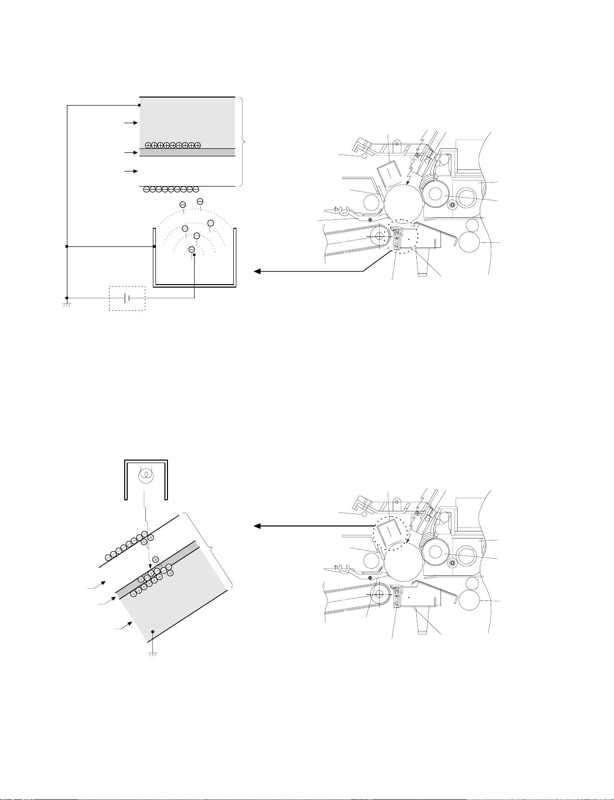
(3) Actual process
Step 1 (charging)
The OPC drum is negatively charged by corona discharge of the
transfer charger . Positive charges are generated in the aluminum
layer.
Aluminum layer
OPC drum
CGL
CTL
Seperation pawl
Transfer corona unit
High voltage unit
Step 2 (Discharging)
When the OPC drum is exposed to the discharge lamp light, positive
and negative charges are generated in the OPC drum CGL. The
negative charges move to the positive charges generated in the
aluminum layer in step 1, and the positive charges move to the
negative charges on the OPC drum surface charged in step 1. The
positive charges and the negative charges are neutralized each other
in the aluminum layer and on the OPC drum surface. As a result, the
OPC dru m surface potential becomes 20V ∼ 30V.
Discharge lamp
Cleaning blade
Main corona unit
Seperation corona unit
Blank lamp
Devel oper u nit
MG roller
Resist roller
Transfer corona unit
Discharge lamp
Light
OPC drum
CTL
CGL
Aluminum layer
By performing step 1 (Charging) and step 2 (Discharging), the
photoconductor itself is initialized to stabilize the drum surface potential.
Discharge lamp
Cleaning blade
Seper ati on pa w l
Main corona unit
Seperation corona unit
Blank lamp
Devel oper u nit
MG roller
Resist roller
Transfer corona unit
5 – 7
Page 30
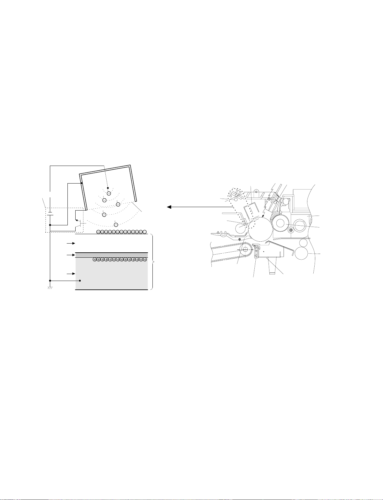
Step 3 (Main Charging)
By negative discharging of the main charger, uniform negative charges are applied to the OPC drum surface.
The OPC drum surface potential is controlled by the screen grid
voltage to maintain the grid voltage at a constant level.
• When the drum surface potential is lower than the grid voltage,
electric charges generated by discharging of the charger go
through the screen grid to charge the drum surface potential until it
becomes equal to the grid voltage.
• When the drum surface potential virtually reaches the grid potential
level, electric charges generated by discharging of the charger
flows through the electrode of the screen grid to the high voltage
unit grid voltage output circuit, thus always maintaining the drum
surface potential at a level virtually equal to the grid voltage.
• The main corona unit employs the scorotron system to charge the
photoconductor surface to a certain level uniformly.
In addition, the conventional corona wire is replaced with the
corona charging mechanism by saw-teeth plate (stainless steel
plate of 0.1 mm thick). In corona discharge, oxygen molecules in
the air are ionized to generate ozone (O3). The mechanism restrict
the generation of ozone.
Main corona unit
Main corona unit
Blank lamp
High voltage unit
Screen grid
CTL
CGL
OPC drum
Aluminum
layer
Step 4 (Exposure)
Light from the copy lamp is radiated on the document, and the optical
image of the document is reflected by the mirrors and projected
through the lens to the OPC drum.
The lighter portion of the document reflects more light (high intensity)
to the OPC drum, and the darker portion of the document reflect less
light (low intensity) to the OPC drum. Positive or negative charges are
generated in the CGL of the OPC drum where lights are radiated.
Negative charges generated in the CGL move towards the positive
charges in the aluminum layer generated in step 3. While the positive
charges in the CGL move towards the negative charges on the CPU
drum surface generated in step 3. Therefore, positive charges and
negative charges are neutralized in the aluminum layer and the OPC
drum surface at the light radiating position, decreasing the OPC drum
surface potential. The CGL electric charge generating amount increases in proportion to the document density, that is, reflected light
intensity (the OPC drum surface intensity). Therefore, electric charges are generated less in the CGL layer corresponding to the lighter
density of document (higher intensity of the OPC drum surface), and
a greater quantity of the negative charges on the OPC drum surface
is neutralized, decreasing the OPC drum surface potential more.
Discharge lamp
Cleaning blade
Seperation pawl
Seperation corona unit
On the contrary, electric charges are generated more in the CGL
layer corresponding to the darker density of document (lower intensity
of the OPC drum surface), and less quantity of the negative charges
on the CPU drum surface is neutralized, decreasing the OPC drum
surface less. Therefore, the OPC drum surface potential corresponding to the lighter portion of the document is lower, and that corresponding to the darker portion of the document is higher. Latent
static-electricity images are formed in the above manner.
Transfer corona unit
Developer unit
MG roller
Resist roller
5 – 8
Page 31

CTL
CGL
Low intensity in
the area corresponding to the
darker density
portion of the
document
Medium intensity
in the area corresponding to the
medium density
portion of the
document
HIgh intensity in
the area corresponding to the
lighter density of
the document
Aluminum
layer
OPC drum
Surface potential
(High)
CTL
CGL
Surface
potential
(Medium)
Surface
potential
(Low)
Aluminum
layer
OPC drum
Step 5 (Development)
Toner is attached to the latent static-electricity images on the drum
surface to change them to visible images. The two-component magnetic brush development system charges toner positively by friction
with carriers, and toner is attached to negative charges on the drum
surface. The potential in the darker document projecting area (low
intensity) is high (much negative charges) and attracts more toner.
The potential in the lighter document projecting portion (high intensity) is low (less negative charges), and attracts less toner.
Discharge lamp
Cleaning blade
Seperation pawl
Main corona unit
Seperation corona unit
Blank lamp
Developer unit
MG roller
Resist roller
Transfer corona unit
OPC drum
CGL
Aluminum layer
Higher surface
potential
(Much negative
(charges)
Medium surface
potential
(Less negative
(charges)
Lower surface
potential
(No negative
(charges)
CTL
MG roller
-200V
High voltage unit
bias voltage
At that time, a bias of –200V is applied to the MG roller (magnet
roller), which is provided for preventing toner from being attracted by
the residual voltage (about –80V to –100V) in the lighter portion after
exposure.
Discharge lamp
Cleaning blade
Seperation pawl
5 – 9
Main corona unit
Seperation corona unit
Blank lamp
Developer unit
MG roller
Resist roller
Transfer corona unit
Page 32

Step 6 (Transfer)
g
The transfer paper is charged higher than the OPC drum surface
potential by strong negative discharge of the transfer charger, making
the binding force between the transfer paper and toner stronger than
that between the drum and toner, attracting toner to the transfer
paper.
Aluminum
layer
OPC drum
CGL
CTL
Toner
Transfer paper
Seperation pawl
Transfer corona unit
h voltage unit
Hi
Step 7 (Separation)
After transfer, the copy paper and the drum are negatively charged.
Since, however, the negative potential of the copy paper is higher
than that of the drum, a attraction force is applied between the drum
and the copy paper. To avoid this, AC corona is applied to the copy
paper by the separation charger to decrease the copy paper potential
to the same level as the drum surface potential. The attraction between the copy paper and the drum is weakened by this, allowing
separation of the copy paper by its own extending force. If the copy
paper is not separated by the separation charger, it is separated by
the separation pawl mechanically.
Discharge lamp
Cleaning blade
Main corona unit
Seperation corona unit
Blank lamp
Developer unit
MG roller
Resist roller
Transfer corona unit
Aluminum
layer
CGL
CTL
High voltage unit
Seperation corona unit
OPC drum
Toner
Transfer paper
Discharge lamp
Cleaning blade
Seperation pawl
5 – 10
Main corona unit
Seperation corona unit
Blank lamp
Developer unit
MG roller
Resist roller
Transfer corona unit
Page 33

Step 8 (Cleaning)
Residual toner on the drum is removed by the cleaning blade. The
removed toner is sent to the waste toner container by the waste toner
transport screw.
Blade Aluminum layer
CTL
CGL
Residual toner
OPC drum
Step 9 (Discharging)
When the OPC drum is exposed to the discharge lamp light, positive
and negative charges are generated in the OPC drum CGL. The
negative charges generated in the CGL move towards the residual
positive charges in the aluminum layer, while the positive charges in
the CGL move towards the residual negative charges on the OPC
Discharge lamp
Discharge lamp
Cleaning blade
drum surface. Therefore, the positive and the negative charges are
neutralized in the aluminum layer and on the OPC drum surface,
removing the residual charges on the OPC drum surface. As a result,
the OPC drum surface potential becomes 20V ∼ 30V.
Main corona unit
Seperation pawl
Seperation corona unit
Main corona unit
Blank lamp
Developer unit
MG roller
Resist roller
Transfer corona unit
Blank lamp
Residual charge
OPC drum
CTL
CGL
Aluminum layer
Residual cha rge
(4) Transit of photoconductor drum surface potential
-800V
-600V
-400V
-200V
Separate
(OFF)
Clean
DLTransfer
Charge
Exposure
Discharge lamp
Cleaning blade
Seperation pawl
BL
Develop
Dark area
Light area
Seperation corona unit
Transfer
Developing
bias voltage
Transfer corona unit
Separate Clean
Developer unit
MG roller
Resist roller
DL
T (Time)
5 – 11
Residual potential
Page 34

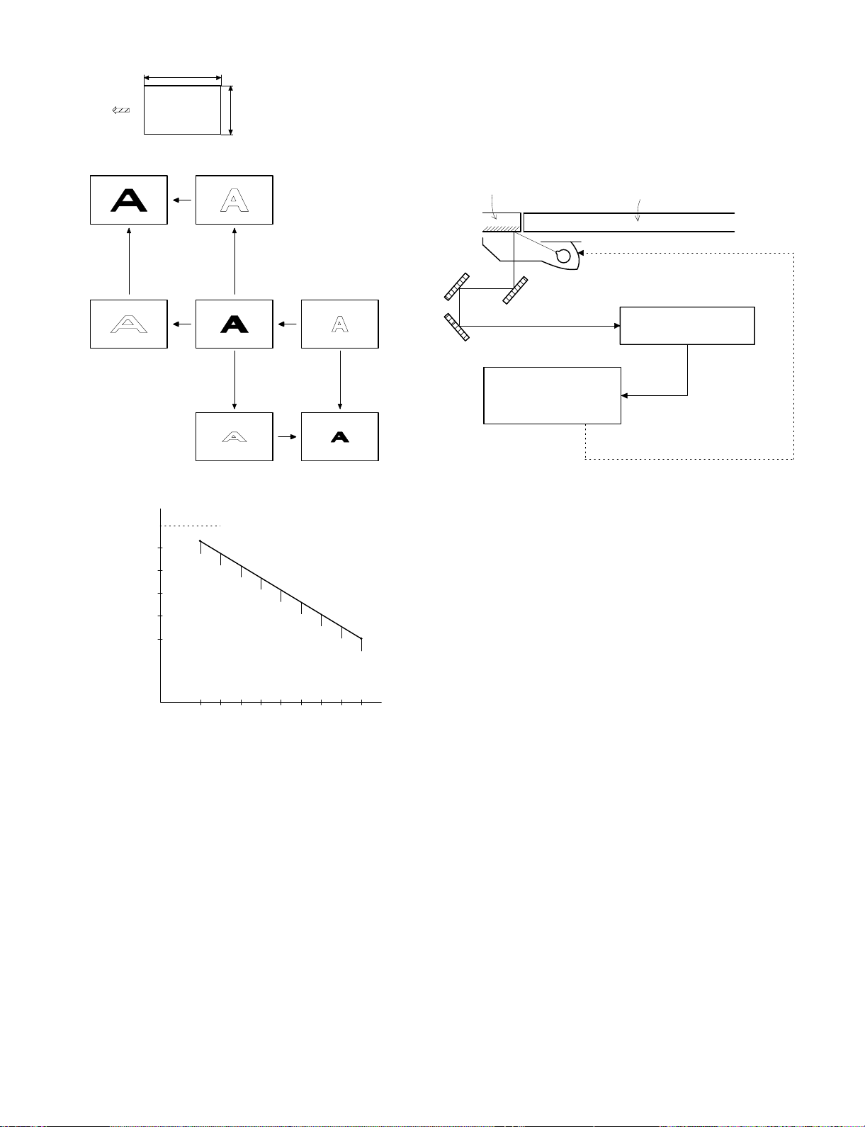
(5) Process correction system
1) Outline of the correction system
This model is provided with the correction system for the optical unit
and the photoconductor drum unit. The combination of the two correction systems provides stable clear copy.
These functions are to maintain the copy quality for a long time and to
correct the characteristics of the parts, and are controlled by the
software and invisible from the outside.
2) Correction operation
1. Photoconductor drum unit correction (Photoconductor
drum sensitivity correction)
Cleaner
Fig. 2
Correction level
(CL voltage)
Fig. 3
VCL
OPC drum
Fig. 1
(NEW)
CTL
CGL
Change the tickness of the carrier transport layer (CTL).
Develop
By the developper.
By the cleaner blade.
Manual mode exposure 1
Correction level is initialized by Simulation 46 or
by repl ac ing the photoco ndu c tor dr um .
1000
200
300 400
(USED)
CTL
CGL
Photo mode exposure 1
Drum rotating time
Wear down
Manual mode exposure 5
Photo mode exposure 5
500
min
The photoconductor drum is subject to mechanical stress by the
cleaning blade, resulting in wear in the OPC layer. In addition to that,
the photoconductor drum receives optical stress from the copy lamp.
These stresses reduce the photo sensitivity of the photoconductor
drum, producing unnecessary dirt copy. This trouble is removed by
adjusting the copy lamp voltage. For this model, however, to reduce
the number of service calls, the copy lamp voltage is automatically
dropped according to the reduction in the photo sensitivity of the
photoconductor drum to correct it.
The drum rotating time from installation of a new photoconductor
drum is counted by the timer and the copy lamp voltage is corrected
in every mode. (Refer to Fig. 3.)
The correction is performed within the range of the max. supply voltage of the copy lamp. (The rotating time of the photoconductor drum
can be checked with Simulation 44-4.)
* The correction level is initialized by Simulation 46 or by replacing
the photoconductor drum.
* Replace the OPC drum for every 40K copies. After replacement,
be sure to reset the drum count value to "0" with SIM 24-7.
The replacement timing of the OPC drum is indicated by lighting
the OPC drum replacement lamp. The copy count of the OPC
drum can be checked with SIM 22-12.
5 – 12
Page 35

2. Optical unit correction (Dirt correction)
Diagram of correction system in the optical section
Referan c e r ef r ection plate
Copy
lamp
AC power supply unit
(Copy lamp control circuit)
AE SENSORMirror
The purpose of this correction is to maintain the copy density even
though the optical unit is contaminated and to reduce troublesome
cleaning of the optical unit.
When the lamp, the mirror, and the reflector are dirtied with dusts and
toner, the light quantity radiated to the photoconductor drum is
reduced, increasing the copy density and producing unnecessary
background copy.
The above trouble is removed by changing the copy lamp voltage to
adjust the copy density. It, however, requires serviceman’s operation.
In this model, the AE sensor senses dirt on the copy lamp, the mirror,
and the reflector, and the copy lamp light quantity is changed according to the dirt level to reduce the change in the copy density due to
the optical unit dirt.
When the optical parts are dirtied, the reflection rate is reduced to
reduce the quantity of light which is passed to the optical dirt sensor.
In this manner the dirt level is sensed.
[Initial setting]
After making a copy by Simulation 46, the scanner unit stops at the
position of the standard reflection plate on the back of the document
stopper to light the copy lamp at a certain level, and the AE sensor
output level at that time is recorded as the reference value. (The
reference value can be checked with Simulation 44-2.)
[Correction timing]
The correction is performed after the copy cycle after turning on the
power, or after the specified time of rotation of the photoconductor
drum.
[Correction operation]
The same operation as the initializing is performed to change the
copy lamp voltage until the AE sensor output level reaches the same
level as the reference value, performing the correction.
The copy lamp voltage is revised to a new value at every correction,
and the new value will be used in the next correction.
(The correction voltage value can be checked with Simulation 44-3.)
[Correction timing]
• When the power is turned on.
• Once for every 155 min. of drum rotation.
AMP
Driver
Referan c e r ef r ection plate
MAIN CONTROL PWB
A/D
converter
START
The scanner starts
initializing.
The scanner unit stops
at the standard reflection
plate position.
Correction mode ?
YES
Copy lamp ON
(67.7V/135V)
Optical di rt sensor
reference level
(DSENS) memory
END
CPU
Timer
Arithmetic unit
Copy lamp control
clock generator
NO
Copy lamp ON
(67.7V/135V)
Sensor output =
Reference level
(DSENS) ?
No correction is made.
Copy lamp voltage
correction
Table glass
YES
AE sensor
(Next to the lens)
Copy lamp
referance control
level
Copy lamp voltage
0.3V ( 0.6V) up
YES
Sensor output
NO
< Reference level
(DSENS) ?
Copy lamp correction
voltage calculati on
EE-PROM
NO
Copy lamp ON
Sensor output =
Referenc e level
Copy lamp voltage
0.3V (0.6V) down
Copy lamp ON
Sensor output =
NO
Reference level
(DSENS) ?
YES
(DSENS) ?
YES
5 – 13
Page 36

[6] DISASSEMBLY AND ASSEMBLY
The descriptions of this chapter are divided into the following sections:
1. Paper feed section, paper transport section, power section
2. Manual paper feed section
3. Fuser section
4. Optical system
5. Drum section
6. Developer section
7. Operation panel/medium cabinet
8. Major parts in the frame side
1.Paper feed section, paper transport
section, power section
1-1. Paper feed unit
1 Open the front cover and open the body. Release the right and
the left lock levers and pull out the manual paper feed unit.
2 Disconnect the CN-B connector of the lower PWB, remove the
paper feed unit fixing screws (4 pcs.), and lift the paper feed unit
to remove.
1-2. Paper feed roller ass’y removal
1 Disconnect the connector of the magnetic clutch in the rear frame
side.
2 Remove the hook section of the paper feed roller bearing in the
front frame side by using a screwdriver.
3 Remove the roller release arm spring from the paper feed frame.
2
3
4
1
6 – 1
Page 37

4 Remove the bearing in the rear frame and remove the paper feed
roller ass’y.
Note for assembly (1): Hang the roller release arm spring on the
spring hook of the roller release arm. Attach the paper feed roller ass’y to the
paper feed unit, and hang the spring on
the paper feed frame.
A
A
Note for assembly (2): Attach the paper feed roller ass’y so that
the paper feed roller clutch faces the
lower frame.
When attaching the paper feed unit, insert
it in the base unit hole of the copier.
1-3. Separation roller
1 Remove the paper feed unit and remove the separation roller.
1-4. Takeup roller, paper feed roller
1 Remove the paper feed roller ass’y, and remove the takeup roller.
2 Remove the roller holder, the stop ring, and the bearing, then
remove the paper feed roller.
6 – 2
Page 38

Note for assembly (1): Attach the paper feed roller so that the
one-way clutch in the rear frame side. (Be
careful to the installing direction.)
Attach the roller holder as shown below:
One-way clutch side
3 Remove the clutch, and the gear as shown below:
1-5. Resist roller
1 Insert a screwdriver into the front frame hole to release the lock
pawl, and remove the TC case.
2 Disengage the hook section of the bearing in the front frame side,
lift it upward and remove towards the upper frame side. Remove
the spring in the rear frame side. Disconnect the CN-E connector
in the lower frame PWB unit. Slide the resist roller ass’y to the rear
frame side and remove it upwards.
Note for assembly (1): When assembling, attach the positioning
pin of the resist roller clutch in the direction of paper exit.
Note for assembly (2): When assembling the resist roller ass’y to
the copier, attach it over the PS roller
lower mylar and rotate the mylar and
return the mylar to the original position.
(To prevent deformation of the mylar)
6 – 3
1
2
Page 39

1-6. Transport belt
1 Remove the fuser unit.
2 Remove the TC case.
3 Remove the transport belt drive shaft in the TC case from the
holder, and remove the drive shaft in the paper exit side, and
remove the belt.
1-7. Socket holder unit
1 Remove the CN-C connector of the lower unit PWB, the ground-
ing wire, and the red high voltage lead wire (for separation
electrode) which in the socket holder.
2 Remove the two fixing screws in the paper feed side, remove the
pawl from the positioning hole in the paper exit side, and slide it in
the direction of paper feed to remove.
1-8. Lower unit PWB
1 Open the body up, and remove the rear lower cabinet.
2 Remove the connector, the PWB fixing screw (1 pc.), and the
CN-F fixing screws (2 pcs.). Slide the lower unit PWB to the front
frame side and remove it upwards.
1-9. Cassette paper empty detector (CPED1)
1 Remove the rear lower cabinet.
2 Remove the fixing screw and the CN-D connector, and remove
CPED1.
1-10. Power unit
1 Remove the upper and the lower cabinets in the rear side.
2 Remove 12 connectors, two fixing screws, and the grounding
wire. Lift the power unit to remove it upwards.
6 – 4
Page 40

Note for assembly (1): When attaching the harness, be careful to
the connector color and the lead wire
color. (Carefully refer to the indication on
the PWB for connection of the harness.)
Example: YE (WH) → Yellow connector and white lead wire
YE = Yellow, WH = White, BK = Black,
GR = Green, BL = Blue
2. Manual paper feed section
2-1. Manual paper feed roller, manual takeup roller
1 Remove the manual paper feed unit from the copier.
2 Remove the roller auxiliary spring, the manual solenoid connector,
the E-rings in the front and the rear frames, and the bearing.
Remove the manual roller ass’y together with the solenoid holder.
4 Remove the manual arm and the E-ring, and remove the manual
paper feed roller.
Note: Gear 20T has a positioning pin. When removing the
manual arm, be careful not to miss the positioning pin.
Gear 20T (Positioning pin included)
Arrow mark
3 Remove the manual feed takeup roller from the manual arm.
Note for assembly (1): The manual paper feed roller is provided
with the one-way clutch. When attaching
it, attach so that the arrow mark on the
roller is in the E-ring side. (Be careful to
the installing direction.)
2-2. Reverse rotation roller ass’y
1 Remove the manual feed roller ass’y.
2 Remove the reverse roller ass’y from the roller holder.
6 – 5
Page 41

3. Fuser section
3-1. Fuser unit removal
1 Open the front panel
2 Remove the table glass.
3 Turn the open/close lever to the right and open the upper unit
slowly.
4 Remove the connectors (2 pin × 2), slightly lift the right side of the
unit and pull it out.
5 Move the copy lamp unit to the left of the body (the paper exit
side).
6 Disconnect the connector (2-pin) of the dehumidifier heater which
extends from the dark box cover. Insert a long screwdriver (+) into
that port and remove the screw which is fixing the fuser cover.
7 Remove the fuser cover in the direction of arrow A.
8 Remove an E-ring and two connectors.
3-2. Heater lamp replacement
1 Remove the fuser cover fixing screw (1 pc.), and slide it to the
front side, and remove it.
2 While pushing the projection of the Faston terminal connected to
the thermostat, remove the lead wire from the connected section.
3 Remove the lamp holder fixing screw on the top of the rear frame,
and remove the holder.
4 Pull out the heater lamp from the front frame.
For assembly, reverse the disassembly procedures.
A
6 – 6
Page 42

3-3. Upper heat roller ass’y removal
1 Remove the bearing fixing screws (2 pcs.) in the front and the rear
frames.
2 Put the paper guide to the paper exit side and separate the
separation pawl from the roller and fix it.
3 Rotate the fixing screw section of the bearing about 45 degrees
below and pull it upwards.
For assembly, reverse the disassembly procedures.
3-5. Lower cleaning roller and lower heat roller
replacement
1 Remove the fuser unit.
2 Remove the CL roller springs (2 pcs.) which is fixing the lower
cleaning roller from the hook section.
3 Remove the lower cleaning roller.
4 Lift the paper exit guide, and remove the lower heat roller without
making contact between the roller and the scraper.
For assembly. reverse the disassembly procedures.
3-4. Upper separation pawl replacement
1 Remove the fuser unit and remove the cover.
2 Place the fuser unit so that the paper guide is in the lower side.
(The separation pawl is in the upper side.)
3 Remove the tension spring, hold the tip of the separation pawl and
remove it from the supporting section, and tilt it to remove.
For assembly, reverse the disassembly procedures.
6 – 7
Page 43

3-6. Scraper replacement
1 Remove the upper fuser unit.
2 Remove the paper exit paper guide fixing screw (step screw) in
the front frame side, and remove the paper exit paper guide.
Paper exit paper guide
3 Remove the scraper hook section from the paper exit paper guide,
and remove the scraper.
3-7. Thermistor/thermostat removal
Press this projection to desassemble
* Note for assembly
• Be sure to bring the thermistor center into contact with the heat
roller.
• Clean and remove foreign materials from the thermistor surface
with alcohol.
Scraper
Note: When attaching the scraper, be careful not to deform it. Also
be careful to check that the scraper hook section is completely
inserted into the paper exit paper guide.
6 – 8
Page 44

4. Optical system
4-1. Copy lamp replacement
1 Open the body up. Release the lock lever of the manual paper
feed unit and remove the manual paper feed unit.
2 Remove the fixing screws (2 pcs.) in the right upper cabinet, and
remove the right upper cabinet.
3 Remove the fixing screws (4 pcs.) of the glass holder, and remove
the glass holder.
4 Remove the table glass.
4-2. Copy lamp unit replacement
1 Remove the manual paper feed unit, the right upper cabinet, the
glass holder, the table glass, and the operation panel.
2 Move the copy lamp unit to the frame notch (refer to the figure).
3 Remove the terminal section of the copy lamp lead wire. (One
screw and insertion terminal)
4 Loosen the fixing screw of the front and the rear frame wire, fixing
plate and remove the wire from the copy lamp unit.
5 Slide the whole unit forward, and remove the rear frame side
upwards.
For assembly, reverse the disassembly procedures.
Wire fixing screw
5 While pushing the copy lamp electrode in the rear frame, remove
the copy lamp.
For assembly, reverse the disassembly procedure.
Note: Be careful to the direction of the copy lamp installation.
Wire fixing screw
Note: When the copy lamp unit is removed, the position adjustment
must be required when attaching again. Refer to the adjustment item for the work.
4-3. Mirror base drive wire replacement
<Removal>
1 Remove the manual paper feed unit, the right upper cabinet, the
glass holder, the table glass and the operation panel.
2 Remove the fixing screws (2 pcs.) of the left upper cabinet, and
slide to the rear frame side to remove the cabinet.
3 Loosen the fixing screw of the copy lamp unit wire fixing plate, and
remove the wire from the unit.
4 Remove the tension spring (7 in the figure) of the mirror base
drive wire in the paper exit side from the hook section.
5 Slightly shift the mirror base to the paper feed side, and remove
the terminal 1 of the mirror base drive wire.
6 Remove the wire fixing screw of the drive pulley.
<Installation>
1 Set the mirror base to the positioning plate position.
2 Set the terminal side of the mirror base drive wire on the hook
section 1, turn the mirror base pulley 2 outside to wind the wire
around the drive pulley from the above.
3 Wind the wire 8 turns from the outside to the inside of the drive
pulley, and put the 7th turn into the groove, and fix it with a screw
temporarily.
4 Pass the wire under the mirror base and wind around the paper
exit pulley (the larger one).
5 Pass the wire to the inside of the mirror base pulley, and pass
through the paper exit pulley (the smaller one), then fix the tension
spring to the hook section 7.
6 Check that the mirror base is in contact with the positioning plate,
and tighten the wire fixing screw of the drive pulley.
6 – 9
Page 45

2
5
7
2
7
6
4
5
6
4
2
5
2
5
1
1
3
3
Note: After replacement of the mirror base drive wire, perform the
vertical skew copy adjustment, the focus adjustment, and the
horizontal skew copy adjustment.
4-4. Lens and lens drive wire replacement
<Removal>
1 Remove the manual paper feed unit, the right upper cabinet, and
the table glass.
2 Remove the dark box cover fixing screw (1 pc.) and the cover.
3 Shift the lens carriage unit to the paper feed side.
4 Remove the tension spring of the lens drive wire from the hook
section, and remove the wire.
5 Remove the shaft mounting plate in the paper feed side, and
remove the shaft and the carriage unit.
<Installation>
1 Pass the lens drive shaft through the carriage unit, and set the
shaft to the shaft support section of the base plate.
2 Fix the shaft mounting plate in the paper feed side.
3 Store the lens unit projection in the lens guide rail.
4 Set the lens drive wire on the carriage unit.
5 Align the No.4/5 mirror zoom cam and the carriage unit to the
normal copy position
6 Manually hold and fix the carriage unit, and wind the wire around
the drive gear.
7 Wind the wire around the pulley, pull it slightly and attach the
spring to it, and set the spring on the hook section.
Note: When the lens unit is removed, the right angle adjustment, the
magnification ratio adjustment, and the focus adjustment are
required.
6 – 10
Page 46

Note: When the lens drive wire is removed, the magnification adjust-
ment and the focus adjustment are required.
4-5. No. 4/5 mirror unit and peripheral parts
replacement
1 Remove the manual paper fed unit, the right upper cabinet, and
the table glass.
2 Remove the dark box cover fixing screw (1 pc.) and remove the
cover.
3 Remove the mirror holder spring.
4 Remove the shaft mounting plate, pull out the shaft towards the
paper feed side, and remove No. 4/5 mirror unit.
4-6. Optical unit removal
1 Remove the drum unit and the developer unit.
2 Remove the right cabinet, the left cabinet, the operation panel, the
medium cabinet, and the rear cabinet.
3 Remove three connectors A from the sensors in the rear as
shown in the figure.
4 Remove connector B between the mirror motor and the main
PWB (CN-C).
5 Remove two snap bands C which are binding cables of the
operation panel.
6 Remove the optical unit .
C
A
5 Remove the fixing screw of the center section of the drive pulley,
and remove the pulley.
6 Remove the CN-E connector of the main PWB, remove the drive
motor fixing screws (2 pcs.), and remove the No.4/5 mirror unit
from the mounting secti on (square hole in the bas e plate).
For assembly, reverse the disassembly procedures.
B
A
4-7. Other parts in the optical system
1 Remove the rear upper cabinet.
2 Remove the CN-C connector of the main PWB and the fixing
screws (2 pcs.), and pull out the mirror motor towards the rear
frame.
6 – 11
Page 47

3 Remove the connector and the fixing screw (1 pc.), and remove
the mirror home position sensor (MHPS) towards the rear frame.
4 Remove the connector and the fixing screw and pull out the lens
home position sensor (LHPS) towards the rear frame.
5 Remove the fixing screw (1 pc.) of the upper frame and the screw
and the connector in the rear frame, then remove the main PWB.
4-8. Light adjustment plate/temperature fuse
removal
1 Remove the document glass.
2 Remove the parts as shown in the figure.
6 Remove the connector, the manual paper feed unit, the right
upper cabinet, the table glass, and the dark box cover. Remove
the fixing screw from the above and remove the AE sensor
towards the front frame side.
For assembly, reverse the disassembly procedures.
6 – 12
Page 48

5. Drum section
5-1. Drum unit removal
1 Open the front cover.
2 While pressing down the release lever A, open the toner
cartridge slowly. (Arrow B)
3 Remove the screw and remove the drum unit.
A
6-2. Developer cartridge removal
1 Place the magnet roller of the developer unit on the box to protect
it.
B
6. Developer section
6-1. Developer unit removal
1 Open the front cover.
2 While pressing down the release lever, open the toner cartridge
slowly and remove it.
3 Loosen the step screw A.
4 Pull out the developer unit.
2 As shown in the figure below, open the section which is pressing
the cartridge pawl with a screwdriver, and pull out the developer
cartridge.
6-3. Toner motor removal
1 Remove four short screws A and one long screw B, and the
connector, and separate the toner cartridge section.
A
6 – 13
Page 49

2 Remove two screws C and remove the motor.
6-4. Toner density sensor
8. Major parts in th e frame side
8-1. Ozone filter
1 Remove the document glass.
2 Remove the black sheet and remove the ozone filter.
7. Operation pan el sect io n/med iu m
cabinet
1 Open the front cabinet.
2 Remove three screws A and two harnesses from the operation
panel.
3 Remove the operation panel unit.
A
A
8-2. Optical unit cooling fan removal
1 Remove the rear cabinet.
2 Remove as shown below.
B
A
B
4 When removing the medium cabinet, first remove the process unit
and the developer unit then remove four screws B and remove
the medium cabinet.
6 – 14
Page 50

8-3. Ventilation fan motor
1 Remove the optical unit. (For details, refer to "4. Optical unit
removal.")
2 As shown in the figure below, remove the ventilation fan motor.
8-4. Transport roller clutch
1 Remove the rear cabinet.
2 Remove the transport clutch as shown in the figure below.
8-5. Paper exit sensor
1 Open the front panel.
2 Move the open/close lever to the right and open the upper unit
slowly.
3 Remove the sensor as shown in the figure below.
6 – 15
Page 51

[7] ADJUSTMENTS
The descriptions of this chapter are divided into the following sections:
1. Developer section
(1) MG roller main pole position adjustment
(2) Adjustment of clearance between DV doctor and MG roller
2. Optical section
(1) Lens unit angle adjustment
(2) Mirror unit angle/position adjustment
(3) Image distortion adjustment
(4) Copy image center position adjustment
(5) Focus adjustment
(6) Copy magnification ratio adjustment
(7) Uniformity adjustment
(8) Image loss/void area adjustment
3. Copy density adjustment
(1) Copy Density adjustment timing
(2) Note for copy density adjustment
(3) Necessary thing for copy density adjustment
(4) Copy density adjustment mode
(5) Copy density adjustment procedure
(6) Copy density adjustment table
4. Others
(1) Transfer charger wire installation
(2) DV bias adjustment
(3) Separation charger output adjustment
2 Tie a string to a needle as shown in the figure below.
3 Hold the string and move the needle to the MG roller.
4 Mark the point where the needle makes contact with the MG
roller.
Marking
5 Measure the distance between the marking and the developer unit
bottom A and check that the distance is within 15.1mm. If the
measured distance is outside the range, loosen the MG adjustment plate fixing screw, and move the adjustment plate in the
arrow direction to perform procedures 3 to 5 again.
1. Developer section
(1) MG roller main pole position adjustment
If the MG roller main pole position is improper, the following troubles
may occur:
• Insufficient copy density
• Toner splash
1 Remove the DV unit from the body and remove the DV cover.
DV cover
A
15.1mm
6 Tighten the MG adjustment plate fixing screw.
7 – 1
Page 52

(2) Adjustment of clearance between DV doctor
and MG roller
If the clearance between the DV doctor and the MG roller is improper,
the following troubles may occur:
• Insufficient copy density
• Copy dirt
• Toner splash
1 Remove the DV cover.
2 Loosen the DV doctor fixing screw.
3 Insert a 0.625mm thickness gauge into the clearance between the
MG roller and the DV doctor in the range of 30mm width under the
DV doctor fixing screw.
A
4 Press the DV doctor in the arrow direction and tighten the DV
doctor fixing screw.
5 Check that the clearance of the DV doctor is 0.625 ±0.03mm in
the range of 30mm width under the DV doctor fixing screw.
0.625±0.03mm
MG
30mm
30mm
A
Note: When adjusting, be careful not to scratch the DV doctor.
7 – 2
Page 53

2. Optical section
A. Adjustments list
Classification No. Adjustment content
Parts installation
position
Copy picture quality
For details, refer to the Ref. page.
*
(1)
Lens
(2)
Mirror
(3)
Image distortion adjustment
(4)
Copy image center position adjustment
(5)
Focus adjustment (Resolution
adjustment)
(6)
Copy magnification ratio adjustment
(7)
Uniformity adjustment
(8)
Image loss, void area adjustment
a
Lens unit right angle adjustment
a
No.4/5 mirror unit right angle
adjustment
b
No. 4/5 mirror unit drive cam position
adjustment
a
Horizontal image distortion adjustment
b
Vertical image distortion adjustment
a
Vertical copy magnification ratio
adjustment (normal copy)
b
Vertical copy magnification ratio
adjustment (zoom copy)
c
Horizontal copy magnification ratio
adjustment (zoom copy)
a
Copy image position adjustment
b
Lead edge void area adjustment
End edge void area adjustment
Adjustment
value/Standard
value
— — 7-6
— — 7-7
— — 7-8
— — 7-8
— — 7-11
0 ±1.5 mm — 7-12
*
100 ±0.8% — 7-15
100 ±0.9% — 7-16
100 ±0.8% — 7-16
— — 7-18
Necessary
special tool
— 7-14
* — 7-19
* — 7-23
Ref.
page
B. Notes
When performing the adjustment, observe the following notes:
1) Observe the sequence of procedures shown in the flowchart
below.
2) Adjustment can be started midway in the flowchart only if all the
previous items have been properly adjusted.
3) If the content of an adjustment item in the flowchart is changed,
all the following items must be adjusted accordingly.
Any adjustment item is based on the previous adjustment items
and relates to the following adjustment items.
4) "Sim" in the flowchart stands for "Simulation."
START
(1)-a
Adjust the lens unit inclination
to zero.
(2)-a
Adjust No.4/5 mirror unit inclination
to zero.
Check the lens No. (OL No.)
Obtain the lens reference position set
value from the lens No. table.
Execute Sim48-1 to set the lens
reference position set value.
Obtain the lens reference position set
value in the zo om c o py mode from the
lens No. table.
Execute Sim26-08 to set the lens
reference position set value in the
zoom copy mode.
Set to the normal copy state in the
(2)-b
normal copy mode and set the lens
unit to the normal position. Then fix the
No.4/5 mirror drive cam position to the
specified position.
Fix the blank lamp to the center.
(4)
Fix the lens center position adjustment
rail at the center t e mporarily.
(5)
Fix No.4/5 mirror position to the
center.
1
Standard setting value in the sim48-1 and 26-8 (Reference)
Lens No. –1 0 1 2 3 4 5 6 7 8 9 10 11 12
sim48 77 75 73 72 70 68 67 65 63 61 60 58 56 55
sim26-8 0 1 2 3 4 5 6 7 8 9 10 11 12 13
Lens No. 13 14 15 16 17 18
sim48 53 51 49 48 46 44
sim26-8 14 15 16 17 18 19
7 – 3
Page 54

1'
2'
(3)-a
Make a test chart. (Draw a rectangle
on B4 or 8 1/2" x 14" paper.)
With the document cover open,
make a 90% copy on B4 or
8 1/2" x 14"paper.
Check horizontal image distortion.
The
distances at the
right and the left of the horizontal
copy image line and the black background
made by the blank lamp are equal
to each other.
(3)-b
With the do cument cover closed,
make a 10% copy on B4 or
8 1/2" x 14" paper.
Check that the right corner and the left
corner angles of the copy image are
right angles.
of the copy image equal
With the document cover closed,
make a 100% copy on B4 or
8 1/2" x 14" paper.
Check the copy image vertical
distortion.
four angles of the copy
Make a test chart. (Draw a rectangle at
(4)
the center of B4 or 8 1/2" x 14" paper in
the longitudinal direction.)
YES
Is the
right corner angle
to the left corner
angle ?
YES
Ar e t he
image rectangle right
angles ?
YES
Use the test chart (UKOG-0089CSZZ)
(5)
NO
Change the relative positions of
the rear or the front frame side
NO
scanner drive pulley and the
shaft, and adjust horizontal
image distortion.
Change the height balance of
right and left scanner slide rails,
and adjust so that the corner
NO
angles of the copy imag e
rectangle are equal to each
other.
//9/
Change No. 4/ 5 mi rror height
NO
balance and adjust vertical
image distortion.
or the resolution chart to make a 100%
copy on B4 or 8 1/2" x 14" paper so
that the resolution patterns are copied
at the center and the four corners.
Check the resolution at the center
and the four corners.
Is the center
resolution more than
5.0 lines/mm and are the corner
resolu tions more th an
4.5 lines/mm ?
(6)-a
Set the scale along the document
reference plate (verti cal to the paper
transport direction) and make a 100%
copy on B4 or 8 1/2" x 14" paper.
Compare the scale and its copy
image size.
YES
Are they the same size ?
(6)-b
Make a copy on B4 or 8 1/2" x 14"
paper at the max. enlargement ratio.
(Z oom model only)
Check that the max. enlargement ratio
matches with the copy image size.
(6)-c
Set the scale in the paper transport
direction, and make a copy on B4 or
8 1/2" x 14" paper at 100%.
YES
Are the
enlargement ratio and
the copy image size
matched ?
YES
NO
Change No.4/5 mirror positions
NO
to adjust focus .
Set the Sim48-1 set value smaller.
NO
NO
Is the copy
image greater than the
actual scale ?
Set the Sim26-8 set value smaller.
image greater for the
enlargem ent ratio ?
YES
YES
Is the copy
Set the Sim48-1 set value greater.
NO
Set the Sim26-8 set value greater.
NO
Set the test chart to the document
positioning reference plate, and make
a 100% copy on B4 or 8 1/2" x 14"
paper by cassette paper feed.
Check that the copy image is at the
center of the copy paper.
Is the
copy image at the
center of the copy
paper ?
YES
2
Change the lens rail position so
NO
that the copy image comes at
the center of the copy paper.
Compare the scale and its copy
image size.
Are they the same size ?
YES
Is the S PF installed ?
NO
3
7 – 4
Set Sim48-2 s et value smaller.
NO
YES
Compare the scale and
the copy image in the
paper transport direction.
YES
Is the copy
image grea ter
than the actual
Set a document with th e fixed size
images in the SPF mode and make
a copy on B4 or 8 1/2" x 14" paper
at 100%.
Are th ey the
same size ?
scale ?
YES
Set the Sim48-3 set value
smaller.
NO
Set the Sim48-2 set value greater.
NO
YES
Is the copy
image greater than
the actual scale ?
Set the Sim48-3 set value
greater.
NO
Page 55

3'
(7)
Use a half-tone document and make a
100% copy on B4 or 8 1/2" x 14"
paper in the half tone mode.
Check the uniformity.
Is the uniformity OK ?
YES
Put the scale to the document
reference plate and set in the paper
transport direction.
Set the Sim45 set value to "0."
(8)-a
Set the Sim50-1 set values A and B
to "0."
YES
Change the installing position of
NO
the exposure adjustment plate
to adjust the uniformity.
4'
Make copies at the max. enlargement
ratio and the min. enlargement ratio.
Measure the distances between the
copy image lead edge and the copy
paper lead edge of the max. enlargement copy and the min. enlargement
copy, and compare the two.
0 ± 1.0 mm ?
Make a 100% copy with Sim50-1.
Measure the distance between the
copy image lead edge and the copy
paper lead edge.
0 ± 1.0 mm ?
YES
Change the Sim50-1 set value A
NO
so that the difference is within
the spe c i fied range.
Change the Sim50-1 set value
B so that the difference is
within the specified range.
(SF-2414/2514)
Change the Sim50-1 set value
A so that the difference is
NO
within the specified range.
(SF-2314)
Make a copy on B4 or 8 1/2" x 14"
paper at the max. enlargement rat io
and the min. reduction ratio in the
document table mode.
Measure the distance between the
copy image lead edge and the paper
lead edge of each copy.
Distance in the max. enlargem
L1 =
ent ratio
Distance in the min. reduction
L2 =
ratio
Calculate the Sim50-1 set value from
the following formula.
A = 8.243 x (L1 - L2)
B = 16.0668 x L2 -7.9661 x L1
Set the Sim50-1 set values A and B.
YES
4
Change the Sim45-1 set value
to adjust the end edge void
area.
(8)-b
Make a 100% copy in the document
table mode and check the lead edge
void area. (Document table mode)
+3
0 mm ?
-0
YES
NO
Use a blac k co lo r document and
make a 100% copy on the A4 or
8 1/2" x 14" paper
NO
1 ~ 3mm ?
YES
End
Change the Sim45-1 set value
NO
to adjust the void area.
7 – 5
Page 56

C. Adjustment contents
(1) Lens
a. Lens unit right angle adjustment
I. Summary
By setting the optical axis of the copier body and that of the lens
in parallel with each other, copy image distortion due to the lens
can be reduced.
The horizontal angle of the lens unit slide shaft is changed by
changing the position of the lens unit slide shaft fixing plate.
This adjustment is performed not by checking a copy image, but
by visual measurement with the mark on the optical unit base as
the reference.
The copy image distortion must be adjusted not only in this
adjustment but also in the mirror parallelism adjustment.
II. Purpose
The purpose of this adjustment is to reduce copy image distortion due to the lens by setting the optical axis of the copier body
and the optical axis of the lens in parallel with each other.
III. Note
The copy image distortion adjustment is completed by making a
copy and adjusting parallelism of the mirror.
For that purpose, this adjustment must have been properly performed.
IV. Cases when the adjustment is required
1) When the lens or the lens unit is disassembled or its part is
replaced.
2) When the copy image is distorted as follows (because of
different copy magnification ratios in different sections):
Large copy
magnification ratio
Normal copy
magnification ratio
Small copy
Document Copy
V. Necessary tool
Screwdriver (+)
*
VI. Adjustment procedure
1) Remove the right upper side cabinet and the document reference plate.
magnification ratio
Optical unit cover
4) Hold section A of the lens unit slide, and move the lens unit
side section to the mark on the optical unit base.
Section A
Optical unit
base
5) Loosen the lens unit slide shaft fixing screw.
Mark
Document
reference plate
2) Remove the document glass.
3) Remove the optical unit cover.
Document table glass
Right upper side cabinet
7 – 6
B
A
Center mark
Lens unit slide shaft
fixing plate
6) Fix the lens unit slide shaft fixing plate in the center mark
position.
A
B
Page 57

VII. Troubles caused by improper adjustment
(2) Mirror
There are following adjustments of parts installation positions related
to the mirror.
No. 4/5 mirror unit right angle adjustment
*
No. 4/5 mirror unit drive cam position adjustment
*
a. No. 4/5 mirror unit right angle adjustment
I. Summary
Copy image distortion caused by No. 4/5 mirror unit van be
reduced by setting the optical axis of the copier and No. 4/5
mirror unit.
The horizontal angle of the lens unit slide shaft is adjusted by
changing the position of No. 4/5 mirror nit slide shaft fixing plate.
This adjustment is performed not by checking a copy image but
by visual measurement with the optical unit base plate as the
reference.
Copy image distortion must be adjusted ont only in this adjustment but also in the No. 1/2 scanner unit parallelism adjustment.
II. Purpose
The purpose of this adjustment is to eliminate copy image distortion by setting the optical axis of the copier and that of the No.
4/5 mirror unit in parallel with each other.
III. Note
The copy image distortion adjustment is completed by making a
copy and adjusting the parallelism of No. 1 and No. 2 scanner
units.
For that purpose, this adjustment must have been properly performed.
IV. Cases when the adjustment is required
1) When No. 4/5 mirror unit is disassembled or its part is
replaced.
2) When the copy image is distorted as follows:
2) Remove the document glass.
Optical unit cover
3) Loosen the fixing screw of the No. 4/5 mirror unit slide shaft
fixing plate.
Document Copy A Copy B
V. Necessary tools:
Screwdriver (+)
*
Scale
*
VI. Adjustment procedure
1) Remove the right upper side cabinet and the document reference plate.
Document
reference plate
Document table glass
B
A
No. 4/5 mirror unit
slide shaft fixing
screw
4) Move the No. 4/5 mirror unit slide shaft fixing plate in directions A and B so that the No. 4/5 mirror unit side is in parallel
with the optical unit frame side plate, and fix it.
Use a scale to check the parallelism.
A
B
Right upper side cabinet
7 – 7
Page 58

VII. Trouble caused by improper adjustment
b. No. 4/5 mirror unit drive cam position adjustment
I. Summary
The copy magnification ratio and focus are properly adjusted by
matching the lens unit movement and the No. 4/5 mirror movement.
This adjustment is performed by changing the relative positions
of the lens unit drive gear and the No. 4/5 mirror unit drive cam.
II. Purpose
The purpose of this adjustment is to adjust the relative positions
of the lens unit drive gear and the No. 4/5 mirror unit drive cam
and to adjust the copy magnification ratio and the focus.
III. Note
IV. Cases when the adjustment is required
1) When the lens and the No. 4/5 mirror drive section are disassembled or its part is replaced.
2) When the focus is improper though the copy magnification
ratio is proper, or vice versa.
V. Necessary tools
Screwdriver (+)
*
M4 x 20 screw
*
VI. Adjustment procedure
1) Set the copy magnification ratio to 100%, and set the lens
unit to the position for 100% copy magnification ratio.
2) Remove the right side cabinet and the document reference
plate.
5) Loosen the No. 4/5 mirror unit drive cam fixing screw without
moving the lens unit drive gear.
Cam
Do not move
Cam fixing screw
6) Turn the No. 4/5 mirror unit drive cam without moving the
lens unit drive gear so that the cam positioning hole is fit with
the reference hole in the optical unit frame.
Requires changing relative
position of cam and gear
Standard fixing position
when having an out of focus
copy in the enlargement
reduction copy mode
Document
reference plate
3) Remove the document glass.
4) Remove the optical unit cover.
Document table glass
Right upper side cabinet
Optical unit cover
Cam fixing
screw
Do not move.
7) Pass the M4 x 20 screw through the No. 4/5 mirror unit drive
cam positioning hole and fix the screw to the frame without
turning the cam.
8) Tighten the cam fixing screw to fix the No. 4/5 mirror unit
drive cam to the lens unit drive gear without moving the lens
unit drive gear.
9) Remove the screw which was fixed to the frame in procedure
7).
VII. Troubles caused by improper adjustment
(3) Image distortion adjustment
There are following two types of image distortion.
Horizontal image distortion
*
Vertical image distortion
*
Image distortion is generated mainly by insufficient parallelism of the
mirror and misalignment of the lens optical axis.
In this model, image distortion is adjusted by adjusting parallelism of
each mirror.
a. Horizontal image distortion adjustment
I. Summary
This adjustment is to adjust horizontal image distortion by setting
the horizontal optical axis of the copier and the horizontal optical
axis of each mirror in parallel with each other. The relative posi-
7 – 8
tions of the front frame and the scanner unit drive pulley of the
frame are changed to perform the above adjustment.
Frame
Reference
hole
Page 59

Install the No. 1 and No. 2 scanner units to the specified positions, adjust the mechanical horizontal parallelism, and perform
the final adjustment while making copies.
II. Purpose
The purpose of this adjustment is to reduce horizontal image
distortion by setting the horizontal optical axis of the copier and
the No. 1 and No. 2 scanner unit horizontal optical axis in parallel with each other.
III. Note
Before starting this adjustment, the following items must have
been completed. If not, this adjustment cannot reduce image
distortion.
The lens unit right angle adjustment must have been com-
*
pleted.
The No. 4/5 mirror unit right angle adjustment must have
*
been completed.
IV. Cases when the adjustment is required
1) When the No. 1 and No. 2 scanner units are disassembled or
their part is replaced.
2) When the scanner unit drive section is disassembled or its
part is replaced.
3) When the copy image is distorted as shown below:
Document Copy A Copy B
V. Necessary tools
Screwdriver (+)
*
Hex wrench
*
Scale
*
Test chart for distortion adjustment (Make a chart shown
*
below by yourself.)
Draw a rectangle on a paper (B4 or 8 1/2" x 14") as shown
below.
Be sure to make four right angles.
2) Remove the document glass.
3) Loosen the fixing screw of the No. 1 scanner unit wire.
Wire fixing screw
Wire fixing screw
4) Manually turn the scanner unit drive gear to bring No. 2
scanner unit into contact with No. 2 scanner unit positioning
plate. When No.2 scanner unit makes contact with No.2
scanner unit positioning plate in the rear frame side simultaneously, the mechanical parallelism of No.2 scanner unit is
proper.
If one side of No.2 scanner unit makes contact with No.2
scanner unit positioning plate and the other side does not,
the parallelism is improper.
If the parallelism is improper, perform the procedure of step
5).
L=10mm
VI. Adjustment procedure
1) Remove the right upper side cabinet and the document reference plate.
Document
reference plate
Document table glass
Right upper side cabinet
5) Loosen the scanner unit drive pulley setscrew in the side where
No.2 scanner unit does not make contact with No.2 scanner unit
positioning plate.
Set screw
Scanner unit drive pulley
7 – 9
Page 60

6) Without moving the scanner unit drive pulley shaft, manually turn the scanner unit drive pulley in the same side of the
loosened setscrew. When it makes contact with No.2 scanner unit positioning plate, tighten and fix the setscrew.
Do not move
the shaft.
No.2 scanner unit
Positioning plate
Scanner unit drive pulley
(Note)
Allow a clearance of about 0.5mm between the scanner
unit drive pulley and the positioning E-ring.
Procedures 1) to 8) are for adjustment of mechanical
horizontal parallelism. No.1 scanner unit and No.2 scanner
unit are fixed to the specified positions and the mechanical
horizontal parallelism of No.2 scanner unit is adjusted.
0.5mm
7) Manually turn the scanner unit drive gear to bring No.2
scanner unit into contact with the positioning plate, and
perform the procedure of step 4).
Repeat procedures of steps 4) to 7) until the parallelism of
No.2 scanner unit is properly set.
8) With No.2 scanner unit being in contact with No.2 scanner
unit positioning plate, and insert the 1.0 mm spacer between No.1 scanner unit and upper-R frame, bring No.1
scanner unit into contact with upper-R frame, and fix it to
the scanner unit drive wire.
No.1 scanner unit
Upper-right frame
Wire fixing
screw
Then the optical horizontal parallelism must be adjusted in
the following procedures.
9) Set the image distortion check chart on the document table,
and make a reduction copy (90%) on an B4 or 14" x 8 1/2"
paper with the document cover open.
50mm
B4 or "11 x 14" size
paper
Wire fixing
screw
1.0mm spacer
7 – 10
Page 61

10) Check the horizontal image distortion.
If LL = LR, there is no horizontal distortion.
LL and LR = Distance between the copy
horizontal line and the outer edge
of the black background
LL
LR
Black background
11) If LL is not equal to LR, perform the following procedure.
Loosen the setscrew of the scanner unit drive pulley in the
front or the rear frame.
Set screw
Scanner unit drive pulley
b. Vertical image distortion adjustment
I. Summary
This adjustment is to adjust parallelism of the vertical optical axis
of the copier and that of each mirror to eliminate vertical image
distortion.
For adjusting vertical image distortion, the overall adjustment
and the right-left balance adjustment must be performed independently.
The overall adjustment is performed by changing the height of
No.4/5 mirror unit in the front frame side. The right-left balance
adjustment is performed by changing the right-left balance of
No.2 scanner unit rail.
The right-left balance adjustment must be performed in advance
to the overall adjustment.
II. Purpose
The purpose of this adjustment is to set parallelism of the vertical optical axis of the copier and that of No.4/5 mirror unit and
No.2 mirror unit to eliminate vertical image distortion.
III. Note
Before performing this adjustment, the following adjustments
must have been completed.
If not, this adjustment cannot be performed properly.
The lens unit right angle adjustment
*
No.4/5 mirror unit right angle adjustment
*
Horizontal image distortion adjustment
*
IV. Cases when the adjustment is required
1) When No.4/5 mirror unit is disassembled or its part is
replaced.
2) When the scanner unit drive section is disassembled or its
part is replaced.
3) When the copy image is distorted as follows:
12) Without moving the scanner unit drive pulley shaft, manually turn the scanner unit drive pulley whose setscrew was
loosened, and adjust the parallelism of No.1 and No.2
scanner units.
Do not move the shaft.
Scanner unit drive pulley
13) Tighten the set screw of the scanner unit drive pulley.
14) Check the image distortion in the same manner as step
10).
Repeat procedures 11) to 14) until horizontal image distortion is eliminated.
VII. Troubles caused by improper adjustment
No.2
scanner
unit.
No.1
scanner
unit
Document Copy C Copy D
V. Necessary tools
Screwdriver (+)
*
Screwdriver (–)
*
Scale
*
Test chart for distortion adjustment (Make by yourself.)
*
Draw a rectangle on A4 or 8 1/2" x 11" paper as shown
below:
Be sure to make four right angles.
L
LL
L = 10mm
L
7 – 11
Page 62

VI. Adjustment procedure
1) Set the test chart for image distortion adjustment on the
document glass, and make a normal copy on a paper of A4
or 8 1/2" x 11".
2) Check image distortion in the right and the left sides.
If the both vertical lines are in parallel with each other, the
right-left distortion balance is proper. (However, there may be
some distortion.)
If all the four angles are right angles, there in no distortion
and the following procedures are not required.
4) Change the height of the roller in No.4/5 mirror unit front
frame side to adjust the vertical image distortion.
If the copy image is tilting as shown in sample (X) below,
lower No.4/5 mirror unit. If it is tilting as shown in sample (Y)
below, lift No.4/5 mirror unit.
Large
distortion
3) If the right-left distortion balance is improper, loosen the
fixing screw of No.2 scanner unit rail to change and adjust
the right-left balance of No.2 scanner unit rail.
(Note)
This procedure is to have the balance between the right
image distortion and the left image distortion, which does not
mean to eliminate the image distortion. Change the height of
No.2 scanner unit rail in the greater distortion side.
If the distortion in the lead edge side (when viewed in the
paper transport direction) is greater, change the height of the
left rail of No.2 scanner unit.
If the distortion in the rear edge side (when viewed in the
paper transport direction) is greater, change the height of the
right rail of No.2 scanner unit.
Change the right side
height of the rail.
Small
distortion
(X) (Y)
5) Make a copy to check the vertical image distortion.
If the four angles are right angles, the adjustment is completed.
Change the left side
height of the rail.
Scanner unit fixing screw
Scanner unit rail
Repeat procedures 2) and 3) until the right-left balance of
image distortion is proper.
Repeat procedures 4) and 5) until the vertical image distortion is eliminated.
(Note) If a vertical image distortion is not eliminated with
procedure 4), change the overall height of No.2
scanner unit rail. Then repeat procedures 1) to 5).
VII. Troubles caused by improper adjustment
(4) Copy image center position adjustment
I. Summary
The optical axis is changed by changing the lens rail position to
optically align the document table and the vertical position of the
copy image on the copy paper.
When the lens rail position is changed, the lens position in the
front and the rear frame direction is changed to change the
optical axis.
As a result, the document table is optically aligned with the copy
image on the copy paper.
II. Purpose
The purpose of this adjustment is to set the copy image center
at the vertical center of the copy paper.
7 – 12
Page 63

III. Note
Before performing this adjustment, the following adjustment
must have been completed. If not, this adjustment cannot be
performed properly.
Lens unit right angle adjustment
*
No.4/5 mirror unit right angle adjustment
*
Image distortion adjustment
*
IV. Cases when the adjustment is required
1) When the lens unit is disassembled or its part is replaced.
2) When the lens rail is disassembled or its part is replaced.
3) When the copy image is shifted from the vertical center of the
paper.
V. Necessary tool
Screwdriver (+)
*
Scale
*
Test chart for center position adjustment (Make a chart
*
shown below by yourself.)
Draw a line in the paper transport direction at the center of A4
or 8 1/2" x 11" paper.
Center
Copy paper
(A4 or 8 1/2" x 11")
5) Remove the right side cabinet and the document reference
plate.
Document
reference plate
Document table glass
Right upper side cabinet
6) Remove the document glass.
7) Remove the optical unit cover.
Optical unit cover
VI. Adjustment procedure
1) Set the test chart for center position adjustment at the document reference position.
2) Make a normal copy (100%) on A4 or 8 1/2" x 11" paper.
3) Check that the image of the line is at the center of the paper.
(Standard: 0±1.5mm)
1.5mm or less
(Copy A)
Shift
1.5mm or less
(Copy B)
Shift
Copy image
Folding of copy paper
Folding of copy paper
Copy image
4) If the image of the line is not at the center of the paper,
perform the following procedure.
8) Loosen the lens rail fixing screw, and slide the lens rail back
and forth.
Lens rail
Fixing screw
7 – 13
Lens unit
9) Make a copy and check that the image line is at the center of
the paper. If not, repeat the procedures 1) to 9) until the
image line comes at the center of the paper.
Page 64

VII. Troubles caused by improper adjustment
(5) Focus adjustment (Resolution adjustment)
I. Summary
The distance between the document and the photoconductor
drum is changed by changing No.4/5 mirror unit drive lever position to adjust the focus.
II. Purpose
The purpose of this adjustment is to correct the lens variations
and the optical section dimensional variations to have good copy
images with a proper focus.
III. Note
Before performing this adjustment, the following adjustment
must have been completed. If not, this adjustment cannot be
performed properly.
Image distortion adjustment
*
IV. Cases when the adjustment is required
1) When the lens or the mirror unit is disassembled or any one
of their parts is replaced.
2) When the scanner unit drive section is disassembled or its
part is replaced.
3) When a copy image of improper focus is obtained.
V. Necessary tools
Screwdriver (+)
*
Test chart (One with the resolution adjustment chart)
*
VI. Adjustment procedures
1) Set the test chart on the document table.
2) Make a normal copy (100%) on A4 or 8 1/2" x 11" paper.
3) Check that resolutions at the copy paper center and the four
angles are as shown in the table below:
(Standard) (Unit: lines/mm)
Copy center Corner
Normal (100%) 5.0 4.5
Enlargement 5.0 4.5
Reduction 4.5 3.6
(Copy)
Check
the corners.
If any resolution is out of the above specifications, perform
the following procedures.
4.5
5.0
5.6
6.3
7.1
8.0
9.0
9.1
9.2
9.2
9.2
9.2 9.2
2.8
3.2
3.6
4.0
4) Remove the right cabinet and the document reference plate.
Document
reference plate
Document table glass
Right upper side cabinet
5) Remove the document glass.
6) Remove the optical unit cover.
Optical unit cover
7) Loosen the fixing screw of No.4/5 mirror unit drive lever to
change the position of No.4/5 mirror unit drive lever or No.4/5
mirror unit.
In this case, do not shake No.4/5 mirror unit, just change its
position.
No.4/5 mirror rive lever fixing screw
No.4/5 mirror drive lever
7 – 14
No.4/5 mirror unit frame
8) Make a copy and check that the resolutions are in the
specified range.
If any resolution is out of the specified range, repeat procedures 1) to 8).
Page 65

VII. Troubles caused by improper adjustment
(6) Copy magnification ratio adjustment
The copy magnification ratio adjustment must be performed in the
vertical direction and in the horizontal direction.
In addition, the horizontal copy magnification ratio adjustment must
be performed both in the document table mode and in the SPF mode.
Firstly perform the vertical copy magnification ratio adjustment, then
perform the horizontal copy magnification ratio adjustment.
a. Vertical copy magnification ratio adjustment (Normal
copy)
I. Summary
The vertical copy magnification ratio adjustment must be performed in the normal (100%) copy mode and in the zoom copy
mode.
In the normal (100%) copy mode, the lens home position is
changed voluntarily with simulations 48-1 to adjust the vertical
copy magnification ratio.
In the zoom copy mode, the lens shift ratio is changed with
simulations 48-1 according to the lens home position set with
simulations 48-1 to adjust the zoom copy magnification ratio.
The vertical copy magnification ratio adjusted in this procedure
is used for the horizontal copy magnification ratio adjustment.
II. Purpose
The purpose of this adjustment is to fit the displayed copy magnification ratio with the actual copy image size.
III. Note
Before performing this adjustment, the following adjustments
must have been completed. If not, this adjustment cannot be
performed properly.
Image distortion adjustment
*
Focus adjustment
*
Firstly adjust the vertical magnification ratio in the normal
(100%) copy mode, then adjust in the zoom copy mode. Never
reverse the sequence.
The vertical magnification ratio adjustment in the zoom copy
mode must be performed when the vertical magnification ratio in
the normal (100%) copy mode is proper but the copy size is not
proper in the zoom copy mode.
The vertical magnification ratio adjustment must be performed in
advance to the horizontal copy magnification ratio adjustment.
Never reverse the sequence. (The horizontal copy magnification
ratio is based on the vertical copy magnification ratio.)
IV. Cases when the adjustment is required
1) When the lens and the mirror unit are disassembled or the
part is replaced.
2) When the scanner unit drive section is disassembled or the
part is replaced.
3) When the main PWB is replaced.
4) When the RAM in the main PWB is replaced.
5) When "U2" trouble occurs.
6) When the position of the lens home position sensor is
changed.
7) When the lens home position sensor is replaced.
8) When the copy image distortion adjustment is performed.
9) When the center position of copy image is adjusted.
10) When the focus is adjusted.
V. Necessary tools
Screwdriver (+)
*
Scale
*
VI. Adjustment procedure
(Normal (100%) copy mode: Vertical copy magnification ratio
adjustment)
1) Set the scale vertically on the document table. (Use a long
scale for precise adjustment.)
Scale
7 – 15
2) Set the copy magnification ratio to 100%.
3) Make a copy on A3 or 11" x 17" paper.
Page 66

4) Measure the length of the copied scale image.
(When a 100mm scale is used as the original.)
mm
10 20
1/2mm
Paper feed direction
mm
1/2mm
10 20
100 110
100 110
JAPAN
120 130
JAPAN
120 130
140
140
150
150
HARDDENCD
STAINLESS
Shizuoka
HARDDENCD
STAINLESS
Shizuoka
Original scale
Reference Comparison point
5) Calculate the vertical copy magnification ratio.
Vertical copy magnification ratio =
Copy image size
Original size
6) Check that the actual copy magnification ratio is within the
specified range (100 ±0.8%).
If it is out of the specified range, perform the following procedures.
7) Execute simulations 48-1. (C → 0 → 0 → C → 48 → CB → 1
→ CB)
The set vertical copy magnification ratio will be displayed in
the COPIES SELECTED display.
8) Enter a new vertical copy magnification ratio with the numeric
key and press PRINT button. The above procedure changes
the lens home position and the vertical copy magnification
ratio.
When the copy magnification ratio is set to a larger value, the
actual copy magnification ratio becomes larger.
When the copy magnification ratio is set to a smaller value,
the actual copy magnification ratio becomes smaller.
Repeat procedures 1) to 8) until the vertical copy magnification
ratio in the normal (100%) copy mode is within the specified
range.
b. Vertical copy magnification ratio adjustment (Zoom
copy)
Scale
x 100 (%)
Copy
110
1) Set a scale vertically on the document table as shown below:
(Use a long scale for precise adjustment.)
2) Set the copy magnification ratio to the max. level.
3) Make a copy on A4 or 8 1/2" x 11" paper.
4) Measure the length of the copied scale image.
5) Calculate the vertical copy magnification ratio.
Vertical copy magnification ratio =
6) Check that the actual copy magnification ratio is within the
specified range (129 ±0.9%).
If it is out of the specified range, perform the following procedures.
7) Execute simulations 26-8. (C → 0 → 0 → C → 26 → CB → 8
→ CB)
The set vertical copy magnification ratio in the zoom copy
mode will be displayed in the COPIES SELECTED display.
8) Enter a new vertical copy magnification ratio with the numeric
key and press PRINT button. The above procedure changes
the lens shift ratio and the vertical copy magnification ratio in
the zoom copy mode.
When the copy magnification ratio is set to a larger value, the
actual copy magnification ratio becomes larger.
When the copy magnification ratio is set to a smaller value,
the actual copy magnification ratio becomes smaller.
Repeat procedures 1) to 8) until the vertical copy magnification
ratio in the zoom copy mode is within the specified range.
VII. Troubles caused by improper adjustment
c. Horizontal copy magnification ratio adjustment (Zoom
copy)
I. Summary
The horizontal copy magnification ratio adjustment must be performed in the document table copy mode. In the document table
copy mode, scanning speed is changed with simulations 48-2 to
adjust the horizontal copy magnification ratio.
Copy image size
Original size
x 100 (%)
7 – 16
Page 67

II. Purpose
The purpose of this adjustment is to fit the displayed copy magnification ratio with the actual copy magnification ratio.
III. Note
Before performing this adjustment, the following adjustments
must have been completed. If not, this adjustment cannot be
performed properly.
Image distortion adjustment
*
Focus adjustment
*
Vertical copy magnification adjustment
*
IV. Cases when the adjustment is required
1) When the lens and the mirror unit are disassembled or the
part is replaced.
2) When the scanner unit drive section is disassembled or the
part is replaced.
3) When the main PWB is replaced.
4) When the RAM in the main PWB is replaced.
5) When "U2" trouble occurs.
6) When the copy image distortion adjustment is performed.
7) When the center position of copy image is adjusted.
8) When the focus is adjusted.
V. Necessary tools
Screwdriver (+)
*
Scale
*
VI. Adjustment procedure
1) Set the scale on the document table as shown below. (Use a
long scale for precise adjustment.)
Scale
2) Set the copy magnification ratio to 100%.
3) Make a copy on A3 or 11" x 17" paper.
4) Measure the length of the copied scale image.
mm
1/2mm
mm
1/2mm
10 20
10 20
100 110 12 0
100 110 12 0
Reference Comparison point Copy
5) Calculate the horizontal copy magnification ratio.
Horizontal copy magnification ratio =
Copy image size
Original size
x 100 (%)
6) Check that the actual copy magnification ratio is within the
specified range (100 ±0.8%).
If it is out of the specified range, perform the following procedures.
7) Execute simulations 48-2. (C → 0 → 0 → C → 48 → CB → 2
→ CB)
The set horizontal copy magnification ratio will be displayed
in the COPIES SELECTED display.
110
Original scale
HARDDENCD
JAPAN
130
140
JAPAN
130
140
8) Enter a new horizontal copy magnification ratio with the
Repeat procedures 1) to 8) until the horizontal copy magnification ratio in the normal (100%) copy mode is within the specified
range.
VII. Troubles caused by improper adjustment
STAINLESS
150
Shizuoka
HARDDENCD
STAINLESS
150
Shizuoka
numeric key and press PRINT button. The above procedure
changes the lens home position and the horizontal copy
magnification ratio.
When the copy magnification ratio is set to a larger value, the
actual copy magnification ratio becomes larger.
When the copy magnification ratio is set to a smaller value,
the actual copy magnification ratio becomes smaller.
Paper feed
direction
7 – 17
Page 68

(7) Uniformity adjustment
I. Summary
The uniformity adjustment is performed by changing the exposure plate position attached to No.1 scanner unit.
The above procedure changes the balance of light quantity
radiated onto the document.
II. Purpose
The purpose of this adjustment is to have uniform copy density.
III. Note
When this adjustment is performed, the exposure will be
changed. Therefore, the copy density adjustment must be performed after this adjustment. Also, this adjustment must be performed always before the copy density adjustment.
IV. Cases when the adjustment is required
1) When the reflector is replaced.
2) When the copy lamp is replaced.
3) When the exposure adjustment plate is disassembled or
replaced.
4) In maintenance
V. Necessary tools
Screwdriver (+)
*
A4 or 8 1/2" x 11" paper
*
Half-tone paper of A4 or 8 1/2" x 11" or larger
*
VI. Adjustment procedure
1) Set a half-tone paper of A4 or 8 1/2" x 11" on the document
table.
2) Set the exposure level to the min. level in the photo mode,
and make a copy on A4 or 8 1/2" x 11" paper.
3) Check the uniformity. If there is any unevenness, perform the
following procedures.
4) Move the exposure adjustment plate of the lighter copy section towards Y or move the exposure adjustment plate of the
darker copy section towards X.
(Example)
If a copy shown below is made, move the front frame side of
the sub exposure adjustment plate in the direction of X to
adjust the exposure balance.
Less exposure
(Dark copy)
Paper exit
direction
Half-tone copy
[Fig. 1]
Standard fixing position
Hole
(Center)
Exposare
adjusting plate
Y
X
Exposare adjusting plate
Y
X
Y
X
5) Make a copy in the same manner as procedure 2), and
check the uniformity.
Repeat procedures 1) to 5) until proper uniformity is obtained.
VII. Troubles caused by improper adjustment
(8) Image loss/void area adjustment
The image loss/void area adjustment is performed by the combination
of the copied image position adjustment on the copy paper and the
void area adjustment.
Since the image loss and the void area are closely related each other,
they must be adjusted simultaneously.
(Definitions of image loss and void area)
Void area: Empty (white) area on a copy paper (without toner on it)
Image loss: The quantit y (le ng th) of an imag e los t on a cop y pa pe r .
(Document)
(Copy)
Paper lead
edge
Li
Li: Lead edge image loss
Lv
Lv: Lead edge void area
(In some cases, Lv
a. Copy image position adjustment
I. Summary
In order to adjust the copy image position on a copy paper, the
lead edge position of an image on the photoconductor for the
lead edge position of a document on the document table is
changed with simulations 50-1, and the relative position of the
paper to the image position on the photoconductor is changed.
In the models which have no zoom copy functions, however, the
lead edge position of an image on the photoconductor for the
lead edge position of a document on the document table is not
changed.
The relative position of the paper is changed at OFF timing of
the scanner home position sensor after starting scanning to adjust the copy image position on the paper.
After adjusting the copy image position with the above procedure, the M.C grid OFF timing for the lead edge position of an
image on the photoconductor is changed with simulations 45-1
to adjust the void area.
II. Purpose
The purpose of this adjustment is to improve separation in the
photoconductor section and in the fuser section and reduce dirt
on the fuser section pawl by obtaining the max. effective copy
area and the paper void area.
Y
X
III. Note
If the proper void area is not obtained, the separation ability in
the photoconductor section may be degraded and dirt on the
fuser section pawl may be increased.
Before performing this adjustment, the following adjustments
must have been completed. If not, this adjustment cannot be
performed properly.
Adjustment of paper pressure against the resist roller
*
(Sim 51-2 set value must be properly set.)
>
Lv)
=
7 – 18
Page 69

IV. Cases when the adjustment is required
1) When the optical section is disassembled or its part is
replaced (including the scanner home position sensor).
2) When the main PWB is replaced.
3) When the RAM in the main PWB is replaced.
4) When "U2" trouble occurs.
5) When the resist roller unit is disassembled or replaced.
6) When the blank lamp is replaced.
V. Necessary tools
Screwdriver
*
Scale
*
Test chart
*
(Copy image position adjustment)
1) Execute simulations 45-1. (C → 0→ 0 → 45 → CB → 1 →
CB)
Simulations 45 is to adjust the size of the void area in the
lead edge of the copy paper.
The set adjustment value is displayed on the COPIES
SELECTED display.
2) Set the set value of simulations 45-1 to "0."
Enter "0" with the numeric key and press PRINT button.
3) Execute simulations 50-1. (C → 0 → 0 → C → 50 → CB →
1 → CB)
This simulation adjusts the copy image position for the
paper. One of the set adjustment values is displayed on the
COPIES SELECTED display.
Adjustment value A: Corresponds to the time interval from
the scanner unit starting and the
scanner home position sensor OFF to
reaching at the lead edge of the
document. That is, this is the value
used to determine the optical document lead edge reference position,
and it must be fit with the edge section of the document reference plate.
If this value is improper, when the
copy magnification ratio is changed,
the copy image lead edge position for
the copy paper edge will fluctuate.
(Does not exist in the models which
have no zoom copy functions.)
Adjustment value B: Corresponds to the time interval from
the scanner unit starting and the
scanner home position sensor OFF to
the resist roller ON.
According to this value, the paper
feed timing for the image on the
photoconductor drum is changed and
the copy image position on the copy
paper is also changed.
When the set value is changed by
"1," the position of the copy image on
the copy paper is changed by about
0.123 mm.
When the set value is made greater,
the copy image position for the copy
paper moves backward. When the
set value is made greater, the copy
image position for the copy paper
moves forward.
Use the paper tray select key to select the display of adjustment value A, adjustment value B, and to select the set
mode.
Display lamp Display content/set mode
Copier tray cassette paper feed
lamp ON.
Copier tray cassette paper feed
lamp BLINKS.
4) Set adjustment value A, adjustment value B to "0."
Enter "0" with the numeric key and press PRINT button.
5) Press the scale onto the document alignment plate and set
it horizontally as shown below:
6) Execute simulations 50-1 to make several copies at each of
129% and 64%.
Scale
7) Measure the distance from the paper lead edge to the copy
image lead edge of each copied papers, and calculate the
average value.
L1: Average distance (mm) from 129% copied paper lead
edge to the copy image lead edge
L2: Average distance (mm) from 64% copied paper lead
edge to the copy image lead edge
L1
mm
10
1/2mm
Scale image lead edge
Adjustment value A
Adjustment value B
20 30
7 – 19
Enlargement copy (x 1.54)
Page 70

L2
LB
10
20
30 40
60
50
70
Scale image lead edge
Reduction copy (x 0.64)
8) Enter the measure values in procedure 7) into the formula
below to calculate adjustment value A and adjustment
value B.
A = 8.2423 x (L1 – L2)
B = 16.0568 x L2 – 7.9661 x L1
9) Set the adjustment values obtained in procedure 8).
10) Execute simulations 50-1 to make several copies at each of
129% and 64%.
11) Measure the distance from the paper lead edge to the copy
image lead edge of each copied papers (129% and 64%),
and calculate the average value.
12) Check that the difference between the distance from the
copy paper lead edge to the copy image lead edge of
129% copy and that of 64% copy is in the range of 0 ± 1.0
mm.
If the difference is out of the above range, change adjustment value A and repeat procedures 10) and 12) until the
difference is within the above range.
If adjustment value A is improper, the copy image lead
edge position fluctuates in proportion to the copy magnification ratio.
LA
10 20 30 40
60 70
50
Scale image lead edge
Reduction copy (x 0.64)
13) Make a 100% copy, and check that the copy image lead
edge is in the range of 0 ±1.5 mm from the paper lead edge
position reference.
If it is out of the above range, change adjustment value B
and repeat procedure 13) until it is within the above range.
Copy scale image
mm
10 20 30
1/2mm
0±1.0mm
Paper lead edge
mm
10 20 30
1/2mm
Scale image lead edge
Enlargement copy (x 1.54)
LA-LB
=±1.0mm
7 – 20
Page 71

b. Void area adjustment
I. Summary
The copy image position on the copy paper is adjusted with
simulations 50-1, then the main corona grid ON timing for the
image lead edge on the photoconductor is changed with simulations 45 to adjust the lead edge void area.
In concrete, in the case of the document table mode, the adjustment is performed by changing the time interval from the scanner motor ON to the main corona grid ON. In the case of the
SPF mode, the adjustment is performed by changing the time
interval from the SPF resist roller ON to the main corona grid
ON.
On the other hand, the rear edge void is adjusted by varying the
OFF timing of the main corona grid after the PPD detects the
rear edge of paper and turns off.
There are two kinds of the rear edge void adjustment. One is in
the tray paper feed mode, and the other is in the manual paper
feed mode.
Selection of the adjustment mode is made by the paper feed unit
select button and the display lamp.
Mode
Paper
tray
Lead edge void amount adjustment mode Light —
Read edge void amount adjustment mode
(Tray feed)
Read edge void amount adjustment mode
(Manual paper feed)
Blink —
— Blink
II. Purpose
The purpose of this adjustment is to improve separation in the
photoconductor section and in the fuser section and reduce dirt
on the fuser section pawl by obtaining the max. effective copy
area and the proper void area.
III. Note
If the proper void area is not obtained, the separation ability in
the photoconductor section may be degraded and dirt on the
fuser section pawl may be increased.
Before performing this adjustment, the following adjustment
must have been completed. If not, this adjustment cannot be
performed properly.
Adjustment of paper pressure against the resist roller
*
(Sim 51-2 set value must be properly set.)
Adjustment of copy image position (Sim 50-1, A, B)
*
IV. Cases when the adjustment is required
1) When the optical section is disassembled or its part is
replaced (including the scanner home position sensor).
2) When the main PWB is replaced.
3) When the RAM in the main PWB is replaced.
4) When "U2" trouble occurs.
5) When the resist roller unit is disassembled or replaced.
V. Necessary tools
Screwdriver
*
Scale
*
Test chart
*
Manual
Paper feed
unit lamp
VI. Adjustment procedure
(Lead edge void area adjustment)
1) Press the scale onto the document alignment plate and set
it horizontally as shown below:
Scale
2) Execute simulations 45-1. (C → 0 → 0 → C → 45 → CB →
1 → CB)
Simulations 45-1 is to adjust the size of the void area in the
lead edge of the copy paper.
The set adjustment value is displayed on the COPIES
SELECTED display.
Press the paper feed unit select button to light the tray
paper feed lamp and set the machine to the lead edge void
adjustment mode.
3) Set the adjustment value to "99."
Enter "99" with the numeric key, and press PRINT button.
4) With the document cover open, make several copies at
100%.
5) Measure the lead edge void area of each copy.
mm
1/2mm
6) Calculate the average void area.
7) Calculate the void area adjustment value from the formula
shown below.
Current set value (99) –
= Adjustment value (Decimal point rounded)
8) Set the adjustment value obtained in procedure 7).
(Decimal point rounded off)
9) With the document cover open, make several copies at
100%.
10) Measure the copy lead edge void area.
Void area
10
20 30
Black background edge
Paper lead edge
B4 or "14 x 8½" paper
Copy scale image
current void area (mm)
0.123
7 – 21
Page 72

11) Measure the distance from the paper lead edge to the copy
image lead edge of each copied papers (129% and 64%),
and calculate the average value.
(Not required for the models without zoom functions.)
12) Check that the void area is within the specified range.
Void area
5) Measure the end edge void area of each copy.
Void area
mm
10
1/2mm
20 30
mm
1/2mm
10
20 30
Copy scale image
Black background edge
Paper lead edge
Standard:
+3
0
mm
–0
If the void area is outside the specified range, change the
set value of simulations 45 and repeat procedures 9) to
12).
When the set value is changed by "1," the void area is
changed by about 0.123 mm.
When the set value is made greater, the void area becomes greater, and vise versa.
(End edge void area adjustment) Tray paper feed mode
1) Set a scale and A4 or 8 1/2" x 11" paper on the document
table as shown below:
Black background edge
Paper end edge
6) Calculate the average void area.
7) Calculate the void area adjustment value from the formula
shown below.
Current set value (99) –
current void area (mm)
0.123
= Adjustment value (Decimal point rounded)
8) Set the adjustment value obtained in procedure 7).
(Decimal point rounded off)
9) With the document cover open, make several copies at
100%.
10) Measure the copy end edge void area.
11) Measure the distance from the paper end edge to the copy
image lead edge of each copied papers (129% and 64%),
and calculate the average value.
12) Check that the void area is within the specified range.
Void area
Scale
B4 or "14 x 8½" paper
2) Execute simulations 45. (C → 0 → 0 → C → 45 → CB → 1
→ CB)
The set adjustment value is displayed on the COPIES
SELECTED display.
Press the paper feed unit select button to blink the cassette
paper feed lamp and to set the machine to the end edge
void adjustment mode in the cassette paper feed mode.
3) Set the adjustment value to "99."
Enter "99" with the numeric key, and press PRINT button.
4) With the document cover open, make several copies at
100%.
mm
10
1/2mm
20 30
Black background edge
Paper end edge
Standard:
1 ∼ 3 mm
If the void area is outside the specified range, change the
set value of simulations 45 and repeat procedures 9) to
12).
When the set value is changed by "1," the void area is
changed by about 0.123 mm.
When the set value is made greater, the void area becomes greater, and vise versa.
(End edge void area adjustment) Manual paper feed tray mode
1) Press the paper feed unit select button to blink the manual
paper feed lamp and to set the machine to the rear edge
void adjustment mode in the manual paper feed mode.
2) Perform the end edge void adjustment in the manual paper
feed mode similarly with the end edge void adjustment in
the tray paper feed mode.
7 – 22
Page 73

3. COPY DENSITY ADJUSTMENT
(1) Copy density adjustment timing
The copy density adjustment must be performed in the following
cases:
✱ When in maintenance.
✱ When the high voltage unit output current or voltage is adjusted.
✱ When the developing bias voltage is adjusted.
✱ When the copy lamp is replaced.
✱ When the optical section is cleaned.
✱ When an optical part is replaced.
✱ When the optical section is disassembled.
✱ When the photoconductor drum is replaced.
✱ When the developer is replaced.
✱ When the AE sensor is replaced.
✱ When the main control PWB is replaced.
✱ When the EEPROM on the main control PWB is replaced.
✱ When the memory trouble (U2) occurs.
✱ When a part of the copy lamp control circuit is replaced.
✱ When the AC power source PWB is replaced.
(2) Note for copy density adjustment
1) Necessary procedures before ad justment
✱ Clean the optical section.
✱ Clean the AE sensor.
✱ Clean or replace the charger wire.
✱ Check that the high voltage section voltage and the developing
bias voltage are in the specified range.
2) Note
✱ The auto mode copy density adjustment must be performed after
the normal mode copy density adjustment. Never reverse the sequence.
(4) Copy density adjustment mode
The copy density adjustment must be performed in the following five
mode:
Exposure
level
Sim No
Original
table copy
mode
Copy density adjustment mode
Normal mode Non-toner-save mode 1 5 46-1
Toner save mode 1 5
Photo mode Non-toner-save mode 1 5
Auto mode Non-toner-save mode 1 5
Toner save mode 1 5
(5) Copy density adjustment procedure
The copy density is adjusted by using Simulations 46 to change the
exposure level and the copy lamp voltage in each copy mode.
The copy density adjustment must be performed in the five modes.
To select each mode, use the copy mode select key.
A. Test chart (UK0G-0162FCZZ) setting
1) Set the test chart and B4 (14 ″ × 8 1/2″) white paper on the original
table as shown below.
The sensing area of the AE sensor is about 120 mm wide from
the rear frame side edge on the original table glass. Place the
white paper on that area, but keep the test chart away from that
area.
White paper
Test chart
120mm
(3) Necessary items for the copy density adjustment
✱ Test chart
(Use one of the following three: UKOG-0162FCZZ, UKOG0089CSZZ, KODAK GRAY SCALE)
✱ B4 (14″ × 8 1/2″) white paper
1 10
5
678
Test chart comparison
UKOG-0162FCZZ
DENSITY No.
UKOG-0089CSZZ
DENSITY No.
KODAK GRAY
SCALE
12345678910W
0.1 0.2 0.3 0.5 1.9 0
123419A
SHARP CORPORATION
9
MADE IN JAPAN
W234
Front side
2) Close the document cover.
3) Execute Sim 47.
4) Cancel the Sim 47 after off the copy lamp.
B. Normal copy mode (Non-toner-save mode) copy
density adjustment
1) Enter the simulations 46-1 mode.
2) Set the adjustment mode to the normal copy mode (Non-tonersave mode).
(Press the copy mode select key to light the normal copy mode
lamp.)
Lighting
Copy mode lamp
AUTO
MANUAL
PHOTO
Copy mode
select key
Copy density display lamp
51
234
Copy density
adjustment key
Copy sheet display
TRAY SELECTEXPOSURE
COPY RATIO
1
5
129%
1
8
117%
100%
1
78%
8
64%
1
8
1
1
x
x
8
8
2
11
2
2
ZOOM
x
x
11 10
14
2
1
x
x
14
8
2
2
x
12x81
5
11
2
%
11
2
7 – 23
Page 74

3) Set the density level to "1" with the copy density adjustment key.
y
j
y
y
j
y
y
j
y
(The currently set copy lamp voltage level will be displayed on the
COPIES SELECTED display.)
Copy mode lamp
Copy density display lamp
Copy sheet display
C. Normal copy mode (Toner save mode) copy density
adjustment
1) Set the adjustment mode to the normal copy mode (Toner save
mode). (Press the copy mode select key to light the normal copy
mode lamp and the photo copy mode lamp.)
Lighting
AUTO
MANUAL
PHOTO
Copy mode
select ke
234
Copy density
ad
ustment ke
TRAY SELECTEXPOSURE
51
COPY RATIO
1
129%
5
12x
8
117%
100%
1
78%
8
64%
1
8
2
2
2
x
11 10
x
14
x
11
1
1
x
8
8
11
2
2
ZOOM
x
14
1
x
8
2
1
x
2
5
%
11
1
2
8
4) Press the print button to make a copy.
Check the gray scale copy to insure that "6" is slightly copied and
"5" is not copied.
When the copy density is too dark, increase the copy lamp voltage
level.
When the copy density is too light, decrease the copy lamp voltage level.
Enter a new set value of the copy lamp voltage level with the
numeric keys and press the print button, then the entered value
will be set and the copy density will be adjusted according to the
set value.
1 10
234567
8
9
W
Slightly copied
Not copied
5) Set the copy density level to "5" with the copy density adjustment
key.
(The currently set copy lamp voltage level will be displayed on the
COPIES SELECTED display.)
Copy mode lamp Copy density display lamp Copy sheet display
Lighting
AUTO
MANUAL
PHOTO
Copy mode
select ke
1234
Copy density
ustment ke
ad
TRAY SELECTEXPOSURE
5
COPY RATIO
5
129%
8
117%
100%
78%
8
64%
8
1
1
12x
1
x
2
x
2
11 10 14
x
2
1
1
x
8
8
11
2
2
ZOOM
x
1
x
8
14
2
1
x
11 5
2
%
11
1
8
2
Adjust in the same manner as the above copy density adjustment
procedures i the normal mode (Non-toner-save mode).
D. Photo copy mode (Non-toner-save mode) copy density
adjustment
There is no toner save mode in the photo copy mode.
1) Set the adjustment mode to the photo copy mode.
(Press the copy mode select key to light the photo copy mode
lamp.)
Copy mode lamp Copy density display lamp Copy sheet display
Lighting
AUTO
MANUAL
PHOTO
Copy mode
select key
5123
4
Copy density
adjustment key
TRAY SELECTEXPOSURE
COPY RATIO
1
5
129%
1
8
117%
100%
12x
78%
8
64%
8
2
2
1
2
x
1
8
x
11 10 14
14
x
11 5
1
x
8
11
2
2
ZOOM
x
1
x
8
2
1
x
2
%
11
1
8
2
Copy mode lamp Copy density display lamp Copy sheet display
Lighting
AUTO
MANUAL
PHOTO
Copy mode
select ke
1234
Copy density
ad
ustment ke
TRAY SELECTEXPOSURE
5
Lighting
COPY RATIO
5
129%
8
117%
100%
78%
8
64%
8
1
1
1
x
x
2
8
8
2
11
2
ZOOM
1
x
x
2
11 10
14
12x
1
x
8
11
14
2
1
1
1
x
x
11 5
2
8
2
2
6) Press the print key to make a copy.
Check the gray scale copy to insure that "2" is clearly copied and
"1" is not copied.
When the copy density is too dark, increase the copy lamp voltage
level.
When the copy density is too light, decrease the copy lamp voltage level.
Enter a new set value of the copy lamp voltage level with the
numeric keys and press the print button, then the entered value
will be set and the copy density will be adjusted according to the
set value.
1 10
2
Not copied
34
Copied
56
78
9
Check the gray scale copy to insure that "7" is slightly copied and
"6" is not copied.
When the copy density is too dark, increase the copy lamp voltage
%
level.
When the copy density is too light, decrease the copy lamp voltage level.
Enter a new set value of the copy lamp voltage level with the
numeric keys and press the print button, then the entered value
will be set and the copy density will be adjusted according to the
set value.
1 10
234567
8
9
W
Slightly copied
Not copied
E. Auto copy mode (Non-toner-save mode) copy density
adjustment
1) Set the adjustment mode to the auto copy mode (Non-toner-save
mode). (Press the copy mode select key to light the auto copy
W
mode lamp.)
7 – 24
Page 75

Copy mode lamp Copy density display lamp Copy sheet display
y
j
y
y
j
y
120mm
White paper
Test char t
Front side
y
j
y
Lighting
AUTO
MANUAL
PHOTO
234
TRAY SELECTEXPOSURE
51
COPY RATIO
1
129%
5
1
8
117%
100%
1
78%
8
64%
12x
8
x
2
8
x
2
11 10 14
x
14
2
11 5
1
1
x
2
2
8
11
x
1
x
8
11
2
1
1
x
2
8
F. Auto copy mode (Toner save mode) copy density
adjustment
1) Set the adjustment mode to the auto copy mode (Toner save
mode).
ZOOM
%
2
(Press the copy mode select key to light the auto copy mode lamp
and the photo copy mode lamp.)
Copy mode
select ke
Copy density
ad
ustment ke
2) Set the density level to "1" with the copy density adjustment key.
(The currently set copy lamp voltage level will be displayed on the
COPIES SELECTED display.)
Copy mode lamp Copy density display lamp Copy sheet display
Lighting
AUTO
MANUAL
PHOTO
Copy mode
select ke
234
Copy density
ad
ustment ke
TRAY SELECTEXPOSU RE
51
COPY RATIO
1
5
129%
1
8
117%
100%
12x
78%
8
1
64%
8
x
2
x
2
x
2
1
8
2
11 10 14
8
14
11 5
1
x
8
2
11
ZOOM
x
1
x
2
1
x
2
%
11
1
8
2
3) Set the copy lamp voltage level set value to "0."
Enter the new set value with the numeric key and press the print
button, then the entered value will be set. (Be sure to set to "0.")
4) Set the copy density level to "5" with the copy density adjustment
key.
(The currently set copy lamp voltage level will be displayed on the
COPIES SELECTED display.)
Copy mode lamp Copy density display lamp Copy sheet display
Lighting
AUTO
MANUAL
PHOTO
TRAY SELECTEXPOSURE
51234
COPY RATIO
5
129%
8
117%
100%
78%
8
64%
8
1
1
12x
1
x
2
8
x
2
11 10 14
14
x
2
11
1
1
x
2
2
8
x
1
x
8
11
2
1
x
5
8
2
11
ZOOM
%
1
2
Copy mode lamp Copy density display lamp Copy sheet display
Lighting
AUTO
MANUAL
PHOTO
Copy mode
select key
51234
Copy density
adjustment key
TRAY SELECTEXPOSURE
Lighting
COPY RATIO
1
5
129%
12x
8
117%
100%
12x
78%
8
1
64%
8
1
1
x
x
8
8
11
2
2
2
ZOOM
x
11 10
14
1
x
8
11
14
2
1
1
x
x
2
11 5
2
8
2
5) Press the print button to make a copy.
Check the gray scale copy to insure that "3" is slightly copied and
"1" is not copied.
When the copy density is too dark, increase the copy lamp voltage
level.
When the copy density is too light, decrease the copy lamp voltage level.
Enter a new set value of the copy lamp voltage level with the
numeric keys and press the print button, then the entered value
will be set and the copy density will be adjusted according to the
set value.
1 10
5
678
9
Slightly copied
Not copied
Copy mode
select ke
Copy density
ad
ustment ke
Adjust the copy density in the same manner as the Photo copy mode
%
W234
(Non-toner-save mode) copy density adjustment.
7 – 25
Page 76

A : Auto copy mode N.TS : Non-toner-save mode
(6) Copy density adjustment table
P : Photo copy mode TS : Toner save mode
N : Normal copy mode
Copy mode Mode display Density level Test chart copy density
1 10 W2
34
56
1
N.TS N
Not copied
1 10
2
34
56
5
Normal
Not copied
1 10
2
Copied
34
56
1
TS N & P
Not copied
1 10
2
34
56
5
2
Copied
34
56
Not copied
1 10
78
Slightly copied
78
78
Slightly copied
78
78
9
9
9
9
9
W
W
W
W
Photo N.TS P
N.TS A
Auto
TS A & P
1
Slightly copied
Not copied
1 10
2
34
56
78
9
W
5
Not copied
Copied
1
1
234
56789
10 W
5
Slightly co pie d
Not copied
1 10
2
3456789
W
1
Slightly co pie d
Not copied
5
7 – 26
Page 77

4. Others
(1) Transfer charger wire installation
Install the transfer charger wire as shown below. (Clean the charger
wire at every 40K copies and replace it at every 80K copies.)
Transfer charger unit (TC unit)
10 0.5
(Note for replacement of the charger wire)
a Do not twist or deform the charger wire.
b After replacement, be sure to clean the charger wire with alcohol.
(Be sure to use alcohol only.)
c After wiping with alcohol, wipe with a dry cloth.
d Use charger wire of 70µ (DWIR-0466CSZZ).
Cut the wire at the
Tension spring
2~3mm
root of the screw
Wind two turns and
tight en t he sc rew
(2) How to adjust the separation corona voltage
1) Install the developer unit and OPC drum unit into the main body.
2) Set the hight voltage probe (1000:1) to digital multimeter.
3) Set the digital multimeter range to DC V.
4) Connect the digital multimeter to the SHVG check pin on the lower
unit control PWB and chassis GND.
5) Execute simulation 8-7 and adjust the separation corona voltage
to 3.5 ± 0.35v by rotates VR1 on the lower unit control PWB.
(SHVG turns on 30 sec)
(3) How to adjust the developing bias voltage
1) Install the developer unit and OPC drum unit into the main body.
2) Set the digital multimeter range to DC 500V.
3) Connect the digital multimeter to the developing bias output terminal on the lower unit control PWB and chassis GND.
4) Execute simulation 8-1 and adjust the developing bias voltage to
–200 ± 3v by rotates VR2 on the lower unit control PWB.
(Developing bias turns on 30sec)
Charger wire
Improper
Charger wire
Improper
CORONA VOLTAGE IN THE EACH COPY MODE
MAIN CORONA UNIT
COPY MODE
N.T.S NORMAL –5.3Kv 780 –5.3Kv +2.7Kv
AE –5.3Kv 780 –5.3Kv +2.7Kv
PHOTO –5.3Kv 478 –5.3Kv +2.7Kv
T.S NORMAL –5.3Kv 660 –5.3Kv +2.7Kv
AE –5.3Kv 660 –5.3Kv +2.7Kv
MAIN CORONA VOLTAGE
(V)
MAIN CORONA GRID
VOLTAGE (V)
TRANSFER CORONA
VOLTAGE (V)
SEPAREATION CORONA
VOLTAGE (V)
7 – 27
Page 78

[8] SIMULATIONS
1. Outline
This model is equipped with the simulations feature which allows the
following operations with the keys on the operation panel:
1) Adjustments
2) Setting of sp ec if ic at ions and functions
3) Resetting trouble codes
4) Checking operations
2. Purpose
The purpose of the simulations feature is to improve serviceability in
repairs and adjustments.
Since the mechanical adjustments can be performed electrically, the
above purpose is achieved with low costs.
3. Opera tin g pr oc edu r e
Simulations operating procedure
Start
Press the cle a r ke y
Press the zero key
Press the zero key
Press the cle a r ke y
All l a mps and indicators
on the operation panel go off.
Ready for entry of the main
test command number
Enter the main test command
number with numeric keys
The s et adjus tment v alue or
the counter value is displayed
on the copy quantity display
To change t he set adjustment
value or the counter value,
enter a new value with numeric
keys
The entered value is displa yed
on the copy quantity display
Press the print key
The new set value is stored
Is there a su b co de ?
Press the prin t key
Is the test
NO
command for operati on
check?
Operat i o ns acc or ding to th e
sim u l at ions are perfor med
Do you
perform anot he r
simulations?
Press the cle a r ke y
NO
YES
NO
YES
YES
Press the print ke y
"00" blinks on the copy
quantity display. Ready fo r
entry of the s ub code.
Enter the sub code with
numeric keys
Press the print key
YES
Is the main
code same?
The main sim ulations
number i s displayed o n the
copy quantity display
NO
Is the sub
code display?
Enter a new m ain code
The main code is display on
the copy quantity display
NO
YES
Press the clear key
All the lamps and indicators
on the operation panel go off.
Ready for entry of the main
simulations number
Press the cle a r ke y
End
8 – 1
Page 79

4. Purpose list
Purpose Section Main Sub Function
Adjustments Paper feed section 51 2 Resist amount adjustment
Optical section 26 8 Copy magnification ratio adjustment (zooming)
45 1 Lead edge void amount setting
46 1 Copy density (exposure level) adjustment 8-4
47 AE sensor characteristics value data auto input
48 1 Front-rear direction magnification ratio adjustment (Vertical direction)
2 Paper transport direction magnification ratio adjustment (Horizontal direction)
50 1 Lead edge image position adjustment
Developer 8 1 Developing bias voltage check
25 2 Auto developer adjustment
Process 8 2 MC/TC output check (Normal mode)
3 MC/TC output check (Photo mode)
4 MC/TC output check (Toner save mode)
7 Separation charger (SC)
9 MC/TC/SC output check
SPF 48 4 Exposure correction in enlargement copy of 120% or more 8-5
51 2 Resist quantity adjustment 8-3
Setting Specifications 26 6 Destination setting
30 CE standards setting
Paper feed section 26 12 Manual copy mode setting
Fuser section 26 13 Main motor operation mode setting at warming up
43 1 Fuser temperature setting
2 Fuser temperature setting (in power save)
Process 44 1 Correction mode setting
Counter Maintenance
Operation
check
Trouble
cancel
counter
Drum counter 24 7 Counter value reset
Developer counter 42 1 Counter value reset
Total counter 0 Key
General
(Aging mode)
Paper feed section 30 1 Main body sensor operation check
Optical section 1 1 Mirror base scan operation check
Operation panel 5 1 LED lighting check
Fuser section 5 2 Heater lamp lighting check
Process 5 4 Discharge lamp lighting check
Developer section 10 Toner motor auto operation check
20 1 Counter value reset
21 1 Maintenance cycle setting
22 2 Maintenance cycle display
22 1 Counter value display
22 12 Counter value display
22 6 Counter value display
Counter value display
(Does not enter the
simulation mode.)
7 1 Warm-up time display and aging
4 Omitting warm-up
6 Intermittent operation aging
2 Option tray sensor operation check
2 Optical system sensor operation check
3 Lens operation check
4 Lens operation aging
5 3 Copy lamp lighting operation
5 Blank lamp lighting check
6 2 Separation pawl auto operation check
44 2 Optical system dirt correction reference value display
3 Optical system dirt correction voltage correction value display
4 Photoconductor drum rotation time display
25 1 Toner density sensor operation check/toner density monitor
14 Cancel of troubles other than U2
16 U2 trouble cancel
Ref.
page
8-3
8-5
8-6
8-7
8-7
8-8
8-9
—
8-12
8-9
8-10
8-11
8 – 2
Page 80

5. Details of simulations
PPD
TRC
(SPPD)
(SPFC)
Purpose/kind Section Main
Adjustment Paper feed
section
Optical unit 26 8 Used to adjust the copy magnification ratio in zoom copy.
Contents
code
Sub
code
Description
51 2 Used to adjust contact pressure between paper and the main body resist
roller. (Amount of paper buckle at the resist roller)
Change the set value when the shift between the paper and the image varies.
(Operation/procedure)
When the simulation key operation is performed, the currently set value is
displayed on the COPIES SELECTED display.
Enter the set value with the numeral key and press the print button, and the
entered set value will be stored in the main PWB RAM.
The standard set value is 25.
Tray paper feed mode: Tray paper feed lamp ON
Manual paper feed mode: Manual paper feed lamp ON
The set value corresponds to the time interval between when the paper detector (PPD/SPPD) in front of the main body resist roller detects paper and when
the transport roller (TRC/SPFC) turns off.
The greater this time interval is, the greater the contact pressure between the
paper and the resist roller is.
@ The time interval can be set. The
greater the time interval is, the
greater the contact pressure between the paper and the resist
roller is. If the contact pressure is
too great, a paper jam may occur.
If the contact pressure is too
small, variations of image position
for the copy paper becomes
greater. This must be adjusted according to the paper quality.
The lens shift amount in zoom copy is changed to provide suitable magnification ratio.
There is a slight variation in each lens focal distance. If the lenses are shifted
in a same amount in zoom copy, suitable magnification ratio may not be
obtained. To correct this, therefore, each lens is shifted according to its focal
distance.
The lens must be shifted in accordance with its focal distance in zoom copy,
(Operation/Procedure)
When the simulation key operation is performed, the currently set lens number
is displayed.
Enter the lens number with the ready lamp ON and press the print button, and
the entered number will be stored in the main PWB RAM. The lens number is
in proportion to the lens focal distance.
45 1 Used to adjust the copy paper lead edge void and the rear edge void amount.
(Operation/procedure)
When the simulation key operation is performed, warming-up operation is
performed. After completion of warming up, the currently set void amount is
displayed on the COPIES MADE display.
Use the tray select key to select between the lead edge void amount adjustment and the rear edge void amount adjustment mode. The upper tray lamp
will change as shown in the table below.
Mode
Lead edge void amount adjustment
mode
Read edge void amount adjustment
mode (Paper tray)
Read edge void amount adjustment
mode (Manual Paper feed)
Paper cassette
lamp
Light —
Blink —
— Blink
Manual Paper
feed lamp
Enter the set value with the numeral keys and press the PRINT button, and
the set value will be stored.
The standard set value is 50. The void area increases 0.123mm for an increase of the set value by 1.
Ref. page
7-16
7-19
8 – 3
Page 81

Contents
12345
B'
B
A
A'
MAX 85V (170V)
MIN 40V (80V)
Great
Exposure
Small
Light
Copy
density
Dark
Copy lamp
application
voltage
( ): 200V system Density display level in the operation panel
Purpose/kind Section Main
code
Sub
code
Description
Adjustment Optical unit 46 1 Used to adjust the copy density (exposure level) and the copy density gradient
(exposure gradient) in each copy mode.
The exposure level is changed by changing the copy lamp applying voltage.
The adjustment points are exposure levels "1" and "5" in each copy mode.
The copy density (exposure level) and the copy density gradient (exposure
gradient) can be adjusted arbitrarily.
(Operation/procedure)
When the simulation key operation is performed, the currently set exposure
level will be displayed on the COPIES SELECTED display.
Select exposure level "1" or "5" with the copy density adjustment key, and
enter the set value with the numeral keys and press the print button. Then the
set value is stored.
To select each copy mode, use the copy mode key.
Exposure
level
Sim No
Original
table copy
mode
Copy density adjustment mode
Normal mode Non-toner-save mode 1 5 46-1
Toner save mode 1 5
Photo mode Non-toner-save mode 1 5
Auto mode Non-toner-save mode 1 5
Toner save mode 1 5
Copy density level (exposure level (copy lamp applying voltage) to operation
panel density display level)
Ref. page
7-26
In the manual copy mode and the photo copy mode
Set point A (exposure level (copy lamp applying voltage) at copy density level
"1") and point B (exposure level (copy lamp applying voltage) at copy density
level "5"), and the exposure gradient (copy density gradient) and the exposure
level (copy density level) will be set.
A – B characteristic: A great exposure gradient ( copy density gradient ).
A′ – B′ character istic: A small exposure gr adient (copy density gradient) .
Point A and point B can be set arbitrarily.
8 – 4
Page 82

Contents
[V] 80(160) 50(100)
[V]
AE sensor
output level
(AE sensor
light receotion
amount)
Copy lamp application voltage to AE sensor
output characteristics
(When simulation 47 is performed)
Copy lamp application voltage (Exposure amount)
Copy lamp
application
voltage
AE sensor output to copy lamp application
voltage characteristics (AE copy mode)
AE sensor output level (Document density)
Dark Light
Purpose/kind Section Main
code
Sub
code
Description
Adjustment Optical unit 47 Used to store the characteristics of the AE sensor and the optical section for
the change in the copy lamp applying voltage. The exposure level in the auto
copy mode is automatically determined by the stored data and the document
density.
This simulation is used to correct the output characteristics of the AE sensor
output characteristics, which differ in different machines.
(Operation/procedure)
When the simulation key operation is performed, the scanner unit performs
initializing and feeds about 10cm and stops.
When the print button is pressed again, the copy lamp applying voltage changes from 80V (160V) to 50V (100V) by the increment of 5V. The AE sensor
output characteristics at that time are stored in the main PWB RAM.
At that time, the AE sensor gain is automatically adjusted.
This operation must be performed before the copy density adjustment in the
auto copy mode.
48 1 Used to adjust the vertical (Machine front to rear) copy magnification ratio.
The adjustment is performed by changing the lens home position arbitrarily.
(Operation/procedure)
When the simulation key operation is performed, the currently set value is
displayed on the COPIES SELECTED display.
Enter the adjustment value with the numeric key and press the print button,
and the value will be stored in the main PWB RAM.
It is required to make a copy and adjust. However, the rough input value can
be obtained from the following formula:
Input value = Current set value + Magnification ratio correction rate × 10
2 Used to adjust the horizontal magnification ratio.(Lead to Trail)
The adjustment is performed by changing the scanning speed of the scanner
(mirror motor).
(Operation/procedure)
When the simulation key operation is performed, the currently set value is
displayed on the COPIES SELECTED display.
Enter the adjustment value with the numeric key and press the print button,
and the value will be stored in the main PWB RAM.
It is required to make a copy and adjust. However, the rough input value can
be obtained from the following formula:
Input value = Currently set value + copy magnification ratio x 10
Copy magnification ratio = (Document length – Copy image length) ÷
Document length x 100 [%]
4 Exposure correction in enlargement copy of 120% or more
Exposure correction voltage in enlargement copy of 120% or more
V = V + N * 0.3V Nor m al N = 0
V: Reference copy lamp voltage
v: Voltage after exposure correction
Ref. page
7-26
7-15
7-16
8 – 5
Page 83

Contents
A
RRC ON
Mirror unit
scan st art
Reaching the
docu men t le ad
edge position
B
Purpose/kind Section Main
code
Adjustment Optical unit 50 1 Used to adjust the copy image position on the copy paper. 7-19
Sub
code
(Operation/procedure)
The adjustment is performed by changing the three set values A, B.
The zoom machine has two set values, the SPF machine three, but the
normal machine only one.
When the simulation key operation is performed, warming-up is performed
and the ready lamp is lighted. Then the currently set value is displayed on the
COPIES SELECTED display. In the case of the zoom machine, there are
three set values. Every time when the tray select key is pressed, set values A,
B is displayed in turn. In this case, the pause lamp status allows monitoring
the three set values.
Display lamp Set value
Copier tray cassette paper feed
lamp BLINKS.
Tray cassette paper feed lamp ON A
Set all three set values A, B to "0", make copies at 64% and 129% and
measure the shift between the copy paper lead edge and the copy image. Put
the measure values into the following formulas to obtain the rough values of A
and B.
L1 = Shift between 129% copy paper lead edge and copy image (mm)
L2 = Shift between 64% copy paper lead edge and copy image (mm)
A = 8.2423 x (L1 – L2)
It corresponds to the time required for the scanner to reach the document lead
edge image position from starting scanning.
It is, in other word, the value used to determine the optical position of the
document lead edge reference position of the document table, and must be
fitted to the edge section of the document reference plate.
If this value is not proper, the distance between the copy image lead edge and
the purpose edge is varied when the copy magnification ration is varied.
B = 16.0568 x L2 – 7.9661 x L1 (Only in the zoom model)
It corresponds to the timer required for the resist roller (RRC) to turn on from
when the scanner started scanning and reached the optical document lead
edge reference position.
This set value is used to determine the paper feed timing for the image
position on the OPC drum, and the relationship between the paper and the
image is changed.
C = 8.0906 x L3 (timer value) (Only in the SPF machines)
This set value is used to change the paper feed timing for the scanning start
timing (the image position on the OPC drum), and to change the relationship
between the paper and the image position.
Description
B (Only in the zoom machine).
Ref. page
In the non zoom model only set value "A"
Developer unit 8 1 Used to check the developing bias voltage.
(Operation/procedure)
The developing bias voltage is outputted for 30 sec.
25 2 Used for initial setting of toner density when replacing developer. 4-5
8 – 6
7-30
Page 84

Contents
3min
8sec
DV.Bias
M.M
500msec
Purpose/kind Section Main
code
Sub
code
Adjustment Developer unit 25 2 (Operation/procedure)
After 3 minutes from start of stirring of the DV unit after the main motor
rotation, toner density is sampled 16 times during 8 sec, and the average
value is stored as the toner density reference value in the RAM.
With this reference value as the threshold value, the toner density is controlled.
(Note) Do not perform this simulation except for when replacing the developer
with a new one.
If this simulation is performed in the other case, overtoning or undertoning
may occur, resulting in a poor copy quality.
Process 8 2 Used to check the voltage of the main charger and the transfer charger in the
manual and auto copy mode.
The main charger and the transfer charger unit are turned on for 30 sec in the
manual and auto copy mode.
3 Used to check the voltage of the main charger and the transfer charger in the
photo copy mode.
The main charger and the transfer charger unit are turned on for 30 sec in the
photo copy mode.
4 Used to check the voltage of the main charger and the transfer charger in the
manual and auto copy mode..
The main charger and the transfer charger unit are turned on for 30 sec in the
toner save mode. (manual and auto copy mode)
7 Used to check the separation charger voltage. 7-30
The separation charger unit is turned on for 30 sec.
9 Used to check the voltage of the main charger, the transfer charger, and the
separation charger.
The main charger unit, the transfer charger unit, and the separation charger
unit are turned ON for 30 sec.
Setting Specifications 26 6 Used to set the destination.
(Operation/procedure)
When the simulation key operation is performed, the code number of the
currently set destination is displayed.
Enter the code number corresponding to the desired destination and press the
print button, and the specifications for the destination will be set.
Code No. Destination
00 Japan
01 SEC
02 SECL
03 SEEG
04 SUK
05 SCA
06 Other inch series
07 Other AB series
08 LAG
Description
Ref. page
4-5
Grid voltage
–750±10V
Grid voltage
–459.9±10V
Grid voltage
–634.4±10V
30 Setting for CE standards
After pressing the print switch, the currently set code is displayed. Enter the
following set code with the 10-key pad and press the print switch.
0: non CE
1: CE (Set to 1 for the areas of 200V/50Hz.
1: CE (Set to 0 for the areas of 100V/60Hz.)
8 – 7
Page 85

Contents
Purpose/kind Section Main
code
Setting Paper feed unit 26 12 Used to set the manual paper feed mode.
Fuser unit 26 13 Used to set the operation mode of the main motor in warming up.
Sub
code
There are two operation modes: auto and manual. Either of the two can be
set.
(Operation/procedure)
When the simulation key operation is performed, the code number of the
currently set operation mode is displayed.
Enter the code number corresponding to the desired operation mode and
press the print button, and the operation mode will be set.
Code number Operation mode Operation
1 Manual
0 Auto
There are two operation modes: auto and manual. Either of the two can be
set.
(Operation/procedure)
When the simulation key operation is performed, the code number of the
currently set operation mode is displayed.
Enter the code number corresponding to the desired operation mode and
press the print button, and the operation mode will be set.
Code number Operation mode Operation
0 Normal mode
1 Long mode
Description
Ref. page
When the print button is pressed,
copying is started.
When copy paper is set, coping is
automatically started.
The main motor rotates until the
process cleaning is completed.
The main motor keeps rotating
until completion of warming up.
43 1 Used to set the fusing temperature.
(Operation/procedure)
When the simulation key operation is performed, the lower two digits of the
currently set temperature is displayed on the COPIES SELECTED display.
(Example: 75 ——— 175 °C)
Pressing the paper select key under that state allows selection of fusing
temperature by the increment of 5 °C. To set the temperature, press the print
button. (Standard set value: 85 ——— 185°C)
2 Used to set the fusing temperature in the power save mode.
(Operation/procedure)
When the simulation key operation is performed, the lower two digits of the
currently set temperature is displayed on the COPIES SELECTED display.
Pressing the paper select key under that state allows selection of fusing
temperature by the increment of 5 °C. To set the temperature, press the print
button.
*00 → 05 → 10 → 85 → 90 → 95 *: Standard set value
Process 44 1 Used to set the correction modes.
(Operation/procedure)
When the simulation key operation is performed, the code number of the
currently set mode is displayed on the COPIES SELECTED display. Enter the
code number corresponding to the desired correction mode and press the
print button, and the mode will be set.
Code Correction mode
2 Optical system dirt correction enable
4 Photoconductor drum membrane wear correction enable
10 Toner correction control
Set the total of codes of above modes.
Factory setting is "16."
8 – 8
Page 86

Contents
Purpose/kind Section Main
code
Counter Copy count 22 1 Used to check the maintenance count value.
Maintenance 20 1 Used to reset the maintenance counter.
Drum count 24 7 Drum count data is reset.
Developer
count
Operation
check
Paper feed unit 30 1 Used to check the operations of the sensors and detectors in the paper feed
Sub
code
(Operation/procedure)
The maintenance count value is displayed dividedly by two digits three times
on the COPIES SELECTED display.
There is a pause between any two displays. After the longest pause, the top
two digits are displayed.
2 Used to check the set maintenance cycle (maintenance preset counter).
21 1 Used to set the maintenance cycle.
(Operation/procedure)
After performing the simulation key operation, enter the code number corresponding to the desired maintenance cycle listed below.
Code
No.
Set to "4" when shipping.
22 12 Used to check the drum counter value inside the installed OPC drum unit.
42 1 Used to reset the developer count value.
22 6 Used to display the developer count value.
section, and their related circuits.
The operations of the sensors and the detector in the paper feed section can
be monitored by the lamps on the operation panel.
(Operation/procedure)
ON/OFF of the sensors and detectors in the paper feed section can be
monitored with the lamps on the operation panel.
Paper size detector (PWD) Toner empty lamp
Resist detector (PPD) Jam lamp
Paper exit detector (POD) OPC drum lamp
Tray open/close detector (PED1) No.1 paper feed cassette lamp
Manual paper feed detector (PID) Manual paper feed lamp
Maintenance lamp ON cycle Photoconductor lamp ON cycle
1 Every 10,000 copies Every 40,000 copies
2 Every 20,000 copies Every 40,000 copies
3 Every 40,000 copies Every 40,000 copies
4 Lamp not ON Lamp not ON
Sensor name Display lamp
Description
Ref. page
3-4
2 Used to check the operations of the sensors and detectors in the option tray
and their related circuits.
The operations of the sensors and detectors in the option tray can be
monitored with the display lamps on the operation panel.
(Operation/procedure)
ON/OFF of the sensors and detectors in the option tray can be monitored with
the lamps on the operation panel.
The operations of the sensors and detectors in the option tray can be
monitored with the lamps on the operation panel. Used to check the operations of the sensors.
Sensor name Display lamp
Option tray cover open/close detector (CSDSW) Toner empty lamp
Option tray paper feed sensor (CSPPD) Jam lamp
Option tray open/close detector (CPED2) Upper tray lamp
Option tray detector (OCSD) Lower tray lamp
8 – 9
Page 87

Purpose/kind Section Main
1sec
4sec
EXP1~5 voltage
CLV
Full power
code
Operation
Optical unit 1 1 Used to check the operation of the scanner unit and its control circuit.
check
5 3 Used to check the operation of the copy lamp and its control circuit.
Contents
Sub
code
Description
(Operation/procedure)
When the print button is pressed, scanning is performed at the speed corresponding to the currently set copy magnification ratio.
The copy magnification ratio can be set arbitrarily.
2 Used to check the operations of the sensors and detectors in the optical unit
and their related circuits.
(Operation/procedure)
ON/OFF of the sensors and detectors in the optical unit can be monitored with
the lamps on the operation panel.
Sensor name Display lamp
Mirror home position sensor (MHPS) OPC drum lamp
Lens home position sensor (LHPS) Toner empty lamp
3 Used to check the operation of the lens unit and its control circuit.
(Operation/procedure)
The lens unit moves to each position of the following copy magnification ratios
continuously, and stops at each position for about 0.5 sec.
The copy magnification ratio corresponding to each stop position of the lens is
displayed on the operation panel.
10% → Reduction 1 → Reduction 2 → Enlargement 1 → Enlargement 2 →
100%
4 Used to check the operation of the optical unit and its control circuit.
(Operation/procedure)
The operation of simulation 1-3 is repeatedly performed.
(Operation/procedure)
The copy lamp lights up for first one sec at full power, and lights for 4 sec at
the currently set exposer level (copy density).
Ref. page
3-4
Operation unit 5 1 Used to check the operations of the lamps on the operations panel and their
control circuits.
(Operation/procedure)
All display lamps on the operation panel turns on for 5 sec.
Fuser unit 5 2 Used to check the operation of the heater lamp and its control circuit.
(Operation/procedure)
The heater lamp turns on for 500ms, and off for 500ms five times repeatedly.
Process 5 4 Used to check the operation of the discharge lamp and its control circuit.
(Operation/procedure)
The discharge lamp lights up for 30 sec.
5 Used to check the operation of the blank lamp and its control circuit.
(Operation/procedure)
The blank lamps lights up sequentially from the rear frame side to the front
frame side, and all the lamps light up for 10 sec.
Operation
check
6 2 Used to check the operation of the OPC separation pawl solenoid and its
control circuit.
(Operation/procedure)
The OPC separation pawl solenoid repeats 0.5 sec ON and 0.5 sec OFF
twenty times.
8 – 10
Page 88

Purpose/kind Section Main
code
Operation
check
Operation
check
Trouble code
resets
Process 44 2 Used to display the reference value of the optical system dirt correction.
Developer unit 10 Used to check the operation of the toner motor and its control circuit.
25 1 Used to check the operation of the sections other than the optical unit and to
Gereral
(Aging mode)
7 1 Warm-up time display and aging
14 Used to cancel troubles other than self diag U2 trouble code.
16 Used to cancel the self diag U2 trouble code.
Contents
Sub
code
This value affects the process correction system. For details, refer to the
descriptions on the process correction system.
3 Used to display the reference value of the optical system dirt correction. 5-13
(Operation/procedure)
When the simulation key operation is performed, the current correction
amount is displayed in hexadecimal number on the COPIES SELECTED display.
The decimal number converted from the hexadecimal number shows the actually corrected copy lamp voltage.
Example --- 1d] : 2.9V correction
4 Used to display rotating time of the photoconductor drum.
This value affects the process correction system. For details, refer to the
descriptions on the process correction system.
(Operation/procedure)
When the simulation key operation is performed, the current rotating time of
the photoconductor drum is displayed in the unit of minute on the COPIES
SELECTED display.
(Operation/procedure)
The toner motor turns on for 30 sec.
check the operation of the toner density sensor.
(Operation/procedure)
The main motor rotates and the units connected to the main motor operate
accordingly. The output level of the toner density sensor is displayed on the
COPIES SELECTED display.
When this simulation is executed, warm-up is started, and the warm-up time is
counted every second and displayed on the copy quantity display. At completion of warm-up, counting is stopped and RPL is lighted.
Press CA key to clear the warm-up time display, set the desired copy quantity
and press the PRINT button, and copying will be performed to make the set
quantity of copies.
4 Omitting warm-up
When this simulation is executed, the machine goes into the ready state (RPL
on).
6 Intermittent aging
When this simulation is executed, warm-up is started.
After completion of warm-up, set the copy quantity and press the PRINT
button, and copying will be performed to make the set quantity of copies.
(Operation/procedure)
After cancellation of the trouble code, the simulation is also automatically
cancelled.
(Operation/procedure)
After cancellation of the trouble code, the simulation is also automatically
cancelled.
Description
Ref. page
5-5
5-13
5-12
8 – 11
Page 89

6. User simulation
[Specifications which does not conform to International
EnergyStar]
A) Preheat mode (The machine enters this mode after passing a
certain time from completion of the final operation.)
• The fusing section temperature is lower than the normal ready
state.
• The fan speed is reduced. (Patent avoidance)
• The energy-saving lamp is turned on and the other display lamps
are also turned on. (Including the ready lamp.)
• Preheat is terminated when any operation is made (key input,
cassette loading, original setting, or other operation which the
machine can detect). The energy-saving lamp blinks. At the same
time, the fusing section temperature rises to the copy ready level
within 10 sec.
B) Auto power shut off mode (The energy-saving effect is greater
than the preheat mode. The machine enters this mode after passing a certain time from completion of copying. When, however, the
machine is temporarily stopped by paper jam, paper empty, toner
empty (with the toner supply lamp ON), etc., the machine does not
enter this mode.)
• Power supply is stopped only to the fusing section.
• The fan speed is reduced. (Patent avoidance)
• The energy-saving lamp is turned on, and the other lamps are
turned off.
• When the print button is pressed, the auto power shut off is ter-
minated and the energy-saving lamp blinks. At the same time, the
fusing section temperature rises to the copy ready level within 10
sec.
• The time from completion of the auto off mode to turning off of the
energy-saving lamp after returning to the ready state is the same
as the max. warm-up time after turning on the power.
Time required to enter the preheat mode or auto off mode and
@
cancellation of the mode can be set by the user program. (For
details, refer to the descriptions on the user program.)
Energy-saving mode Auto start from D, E
Machine state A. Warmup B. Ready C. Copying
Operation panel ON
F
Energy-saving LED
Ready lamp ON
Power switch ON ON ON ON ON ON ON
@1: When the copy button is pressed during preheating, the machine enters the state of "G. Reserved."
Blink
F
ON
F
OFF
D
ON
F
ON
F
OFF
D
OFF
D
D. Preheating
(@1)
ON
F
ON
F
ON
F
E.Auto power
shut off mode
OFF
D
ON
F
OFF
D
F. Resetting
ON
F
Blink Blink
ON
F
G. Reversed
(Reset)
ON
F
OFF
D
Auto start function
Even during warming up or during resetting after completion of energy-saving mode, copy condition can be set and copy reservation can
be accepted.
When reservation is made, copying is started when the fusing
temperature of the machine reaches the specified level.
When copy reservation is made, the copy conditions cannot be
changed until the reservation is canceled with the clear key.
8 – 12
Page 90

(2) User simulation prcedure
Paper jam/
Simulation procedure State
1. Pres s the paper feed section select
key for more than 5 sec.
2. Enter a code number with 10 key. Simulation code selection.
3. Press the COPY button. Simulation code determined.
4. Enter the selection code with 10 key. Simulation code menu selection.
5. Press the COPY button. Simulation code menu determined.
6. Pres s the paper feed section select
key.
User simulation input allowed.
Escape from user simulation.
developer
replacement/
toner supply
warning LED
Blink OFF
Blink ON
Blink ON
Blink ON
Blink OFF
OFF
Copy quantity
display
1
11
21
21
Returns to
copy quantity
display.
Print LED
• When this key is pressed during user
simulation selection, the mode returns to
state 1 (user simulation input allowed.)
* Press the clear key.
(Use this key to correct mistyping of input.) Blink OFF
• After completion of program setting, when
this key is pressed, the mode the following
program input can be made.
( : Blink)
—
(3) User program code table
[ES conforming area]
P
1
2
3
4
5
Selection code:
0: NO
1: 30 sec.
2: 60 sec.
3: 90 sec.
4: 120 sec.
0: NO
1: 30 sec.
2: 60 sec.
3: 90 sec.
4: 120 sec.
1: 30 min.
2: 60 min.
3: 90 min.
4: 120 min.
5: 240 min.
0: NO
1: YES
0: NO
1: YES
Program
Auto clear passing
time setting
Preheat mode
setting and passing
time setting
Auto off mode
passing time setting
Stream feeding
mode setting and
cancel (Only
models with SPF)
Auto power shut off
mode setting, cancel
code
Set content
Factory setting
2: 60 sec.
0: N O
0: N O
Since P code
[5] is set to "[0]:
NO," this
setting is set to
[0] though there
is no selection
code specified.
0: NO
0: NO
When auto power shut off mode passing time setting (operation
@
with P code [3]) is made under the state where the auto power
shut off mode is canceled ("[0]: NO" is selected with P code [5]),
the machine enters the auto power shut off mode set conditions
without operation with program [5].
8 – 13
Page 91

[9] SELF DIAG
1. Summary/purpose
This model has the self diag function for the following purposes:
1) When a trouble occurs in the machine, the machine detects the
trouble and displays the trouble content on the copy quantity display to alert the customer and the serviceman.
2) When any abnormality is detected, the power supply line is cut off
immediately for safety and to protect the machine from damage.
2. Operation
The self diag content is displayed in the following procedure.
A trouble occurs
The abnormalality is detected
by sensors and detectors
The main trouble code is
displayed on the copy
quantity display
YES
Is there
sub code?
NO
Check the trouble position
(Use the suitable simulation)
Repair
Turn off/on the power or
cancel the self diag with
simulation 14 or 16
Press the print key
The sub trouble code
is displayed on the copy
quantity display
3. Clearing the self diag display
After repairing the trouble section, clear the self diag display according to the table below:
Clearing the self diag display
Self diag display Display clearing procedure
L1, L3, L4, L5, L8 Turn off/on the power.
H3, H4 Execute simulation 14.
U2 Execute simulation 16.
CH, PC
When the trouble is cancelled,, the display is
cleared.
9 – 1
Page 92

4. Self diag contents
Error code
Main Sub
L1 0 Content Scanner feed trouble 8-10
L3 0 Content Scanner return trouble 8-10
L4 1 Content Main motor lock trouble
Item Description Ref. page
Detail 1) 86 pulses (45 mm) of the scanner motor drive pulse have been outputted after the
scanner unit started scanning, but the scanner home position sensor (MHPS) does not
turn off.
2) The scanner unit is not at its home position (MHPS does not turn on) when the scanner
unit starts scanning.
3) The scanner home position sensor (MHPS) does not turn on when the scanner
performs the initial operation.
Cause 1) Scanner motor trouble
2) Scanner motor control circuit trouble
3) Scanner motor rotation sensor and its control circuit tr ouble
4) Sc anner home po sition se nsor (MH PS)and its inpu t circuit trouble (main cont rol circ uit
trouble)
5) Scanner unit drive m echani s m trouble
6) An overload to the drive secti on
Remedy Use simulations 1-1 and 1-2 to check the following:
A. Check the mirror motor control circuit and its peripheral sections.
1) The scanner unit operates normally.
2) The scann er home pos iti on se nsor (( MHPS) oper ates n ormal ly an d i ts ou tpu t sig na l is
inputted to the main control PWB.
3) The scanner m otor drive signal is out putted.
4) The scanner motor rotation sensor signal is inputted to the control circuit.
B. Check the scanner unit drive mechanism.
1) Drive wire
2) Pulley
3) Gear
After repair, turn off/on the power switch.
Detail 1) The scanner motor drive pulses required for the scanner unit to return are shifted more
than 50 pulses for the drive pulses required for feeding. (The corresponding distance is
10mm or more.)
2) The scanner motor drive pulses required for the scanner unit to return are within 50
pulses for the dr ive pulses req uired to feed.
3) The scanner unit does not return. Or through it returns, the scanner unit does not
return to its home position (the MHPS does not turn on).
(Though the scanner motor drive pulses required to return are 50 pulses greater than
the drive pulses required for the scanner unit to feed, the scanner unit is not in the
home position (the MHPS does not turn on).
4) After the scanner unit returns, the MHPS does not turn on.
Cause 1) Scanner motor trouble
2) Scanner motor control circuit trouble
3) Scanner motor rotation sensor and its peripher al secti ons trouble
4) Scanner home position sensor (MHPS) and its input circuit trouble
5) Scanner unit drive m echani s m trouble
6) Overload at the scanner motor drive section
Remedy Use simulation 1-1 and 1-2 to check the following:
A. Check the mirror motor control circuit and its peripheral.
1) The scanner unit operates normally.
2) The scanner home position sensor (MHPS) operates normally and its output signal is
inputted to the main control circuit.
3) The scanner m otor drive signal is inputted.
4) The scanner motor rotation sensor signal is inputted to the control circuit.
B. Check the scanner unit drive mechanism.
1) Drive wire
2) Pulley
3) Gear
After repair, turn off/on the power switch.
9 – 2
Page 93

Error code
Main Sub
L4 1 Detail The rotary encoder signal cannot be detected for more than 50ms during delivery of the
L5 2 Content Lens drive motor trouble 8-10
L8 1 Content Power frequency abnormality
3 Content During execution of simulation 47, the AE sensor output does not change according to
Item Description Ref. page
main motor On signal output.
Cause 1) Main moor trouble
2) Main control circuit trouble
3) Main motor rotation sensor and its input circuit (main control circuit) trouble
4) Main motor d rive mechanism trouble
5) An overload on the main motor drive section
Remedy Check the following items:
A. Check the main motor control circuit and its peripheral sections.
1) Main moto r drive signal is inputted .
2) The main motor rotation sensor signal is inputted to the control circuit.
B. Check the main motor drive mechanism.
1) Drive wire
2) Pulley
3) Gear
After repair, turn off/on the power switch.
Detail 1) During the initial operation, the lens does not move from the reduction copy position to
the enlarged copy position. Or the lens home position sensor (LHPS) does not turn on
even though the lens moves (130mm/lens motor drive pulse output).
2) During the initial operation, the lens does not move to the enlargement copy position.
Or the lens moves (70mm/ 50 pulses of lens motor drive pulse are outputted) but the
lens home position sensor (LHPS) does not turn off.
3) When the lens moves from the reduction coy position to the enlargement copy position,
the specified number of pulses required for the lens home position sensor (LHPS) to
move from ON position to OFF position is shifted by 20 pulses (4mm) or more.
4) AT the c ompletion of le ns m ov em e nt , t h e le ns home position s en so r is no t O N when in
enlargement copying, or not OFF when in reduction copying.
Cause 1) Lens motor trouble
2) Main control circuit trouble
3) Lens motor rotation sensor and its in put circ uit (main control PWB) trouble
4) Lens motor d rive mechanism t rouble
5) An overload on lens motor drive mechanism
Remedy Use simulations 1-3 or 1-4 to check the following items:
A. Check the lens motor control circuit and its peripheral sections.
1) The lens motor drive signal is outputted.
2) Lens motor rotation sensor signal is inputted to the control circuit.
B. Check the lens motor drive mechanism.
1) Drive wire
2) Pulley
3) Gear
After repair, turn off/on the power switch.
Detail The power frequency is shifted from the specified level by 5% or more for 10 cycles or
more, or the FW signal cannot be detected for more than 5 sec.
Cause 1) FW is not outputted or the output waveform is abnormal.
2) Power circuit trouble (AC power unit/DC power unit)
3) FW input circuit tr ouble (m ain control circ uit)
4) AC power tr ou ble (wa veform/voltag e)
Remedy Check the waveforms of the following units with an oscilloscope.
1) FW signal waveform in the DC power unit
2) FW signal waveform in the main control circuit
3) AC power line
After repair, turn OFF/ON the power switch.
change in the copy lamp voltage.
Detail AE sensor trouble
Cause 1) AE sensor or its input circuit (main control PWB) trouble
2) Cop y lamp cont rol circ uit troub le (copy lamp control sign al abnormality)
3) A white paper is not set on the document table or the document table or the document
cover is dirty.
8-11
8-5
9 – 3
Page 94

Error code
Main Sub
L8 3 Remedy Check the following items:
H2 0 Content Fuser section thermistor trouble
H3 0 Content Abnormally high temperature in the fuse section 8-11
H4 0 Content An abnormally high temperature in the fuse section 8-11
U2 1 Content In the main PWB EEPROM data sum check, the data do not correspond to the CPU data. 8-12
4 Content memory line communication trouble 8-12
Item Description Ref. page
1) AE sensor or its in put circ uit
2) Cop y lamp cont rol circ uit (copy lamp cont rol signal)
After repair, turn off/on the power switch.
Detail The voltage across the thermistor input circuit remains 4.6V or more for 1500 ms or more.
Cause 1) Thermistor and its input circuit (main control PWB) trouble (disconnection)
Remedy Check the thermistor and its input circuit (main control circuit) for disconnection.
AFter repair, used simulations 14 to cancel the self diag.
Detail The voltage across the thermistor input circuit remains 1.39V or less for 1500 ms or more.
(A high temperature above 241 C is detected.)
CAuse 1) Thermistor and its input circuit (main control PWB) trouble (disconnection)
2) Heater lamp control signal and its co ntrol circuit tr ouble
(The heater lamp remains ON.)
Remedy Check the following items:
1) Ther mistor and its input circuit ( m ain control PWB) disconnection
2) Heater lamp control signal and its co ntrol circuit
After repair, use simulations 14 to cancel the self diag.
Detail 1) The voltage across the thermistor input circuit remain 3.39V o r more for 1500ms. (A
temperature below 148°C is detected.)
2) The tempe rat ure doe s n ot re ach the sp ecifi ed t em perat ure wi thi n 60 sec af ter start ing
warming up.
Cause 1) Thermistor and its input circuit (main control circuit) trouble (disconnection)
2) Heater lamp trouble
3) Heater lamp control signal and its co ntrol circuit tr ouble (The heat er lamp remains ON.)
Remedy Check the following items:
1) Che c k the thermistor a nd its input circuit (main control PWB) for di sconnection or shot.
2) Heater lamp control signal and its co ntrol circuit
3) Heater lamp
After repair, use simulations 14 to cancel the self diag.
Cause 1) Main PWB EEPROM trouble
2) Main control circuit trouble
3) Communication line trouble between the main PWB EEPROM and the CPU
4) CPU trouble
5) Data bus line trouble
Remedy Check the following items:
1) main PWB EEPROM
2) Memory control circuit
3) Communication line between main PWB EEPROM and CPU
4) CPU
5) Data bus line
After repair, use simulations 16 to cancel the self diag.
When the power is turned on, data in the main PWB EEPROM are transferred to the CPU
to perform sum check. The operation can be checked at that time.
Detail 1) In a ccess to the main PWB EEPROM, the respond c ommand ACK is not inputted to
the CPU.
2) When writing da ta in to th e main PWB EEPROM, the writ e e nabl e s igna l is n ot input ted
to the CPU for 11ms or more.
Cause 1) Main EEPROM RAM trouble
2) Memory control circuit trouble
3) Communication li ne trouble between main PWB and CPU
4) CPU trouble
5) Data bus line trouble
9 – 4
Page 95

Error code
Main Sub
U2 4 Remedy Check the following items: 8-12
U5 5 Content Abnormally high temperature on the original glass when using the SPF.
EE EU Content Toner density initial setting trouble (undertoner) 8-6
EL Content Toner density initial setting trouble (overtoner) 8-6
CH Light Content Paper feed section cover open 8-10
Light Content Manual paper feed unit installation trouble (MFD0, MFD1) 8-10
Item Description Ref. page
1) Main PWB EEPROM
2) Memory control circuit
3) Communication line between main PWB EEPROM and CPU
4) CPU
5) Data bus line
After repair, use simulation 16 to cancel the self diag
When the power is turned on, data communication is performed with the main PWB
EEPROM and the CPU. The operation can be checked at that time.
Detail The thermistor detects 55°C or above.
Cause 1) Thermistor and input circuit (main control PWB) trouble (disconnection)
2) Copy lamp control signal and control circuit trouble
(Copy lamp remains ON.)
Remedy Check the following items.
1) Thermistor and inp ut circuit (main control PWB) di sconnection
2) Copy lamp control signal and control circuit
Turn OFF/ON the power to cancel the diagnostics.
Detail When setting the toner density initial level with simulation 25-2, the toner density sensor
output is below the specified voltage (1.53V).
Cause 1) Toner sensor trouble
2) Toner sens or input circuit t rouble (main con tr ol PWB)
Remedy Use simulations 25-2 to check the following items:
1) Toner sensor
2) Toner sens or input circuit
After repair, use simulations 14 to cancel the self diag.
Detail When setting the toner density initial level with simulation 25-2, the toner density sensor
output is above the specified voltage (3.49V).
Cause 1) Toner sensor trouble
2) Toner sens or input circuit t rouble (main con tr ol cir cuit)
3) Toner motor and its control circuit trouble
Remedy Use simulations 25-2 to check the following items:
1) Toner sensor
2) Toner sensor input circuit
3) Toner motor and its control circuit
After repair, use simulations 14 to cancel the self diag.
Detail 1) The paper feed section cover open/close detector (CSDSD) and its input circuit
remains Low (0V).
Cause 1) Paper feed section cover open/close mechanism trouble
2) Pape r feed sect ion cover op en/close d etector sig nal (CSDSW) an d its cont rol circuit
trouble
3) Pap er feed sect ion cove r open/close detector (CSDSW ) troubl e
Remedy check the following items:
1) Paper feed section cover open/close mechanism
2) Paper feed section cover open/close detector signal (CSDSW) and its input circuit
3) Pap er feed secti on cover open/close detector (CSDSW)
Detail 1) The manual paper feed unit signal (CSDSW) and its control circuit remains MFD0 level
and MFD1 level.
Cause 1) The manual paper fee d unit signal (MFD1) line is not connected or disconnection in the
line. (The manual paper feed unit is not installed.)
Remedy Check the following item:
1) Manual paper feed unit signal (MFD1) line
9 – 5
Page 96

Error code
Main Sub
PC Content Personal counter installation trouble
Paper
empty
Toner empty Light Content Toner concentration fall 8-6
Toner empty Blink Content Toner concentration fall (Copy stop) 8-12
JAM Content Copy paper misfeed trouble 8-3
Item Description Ref. page
Detail The personal counter is not installed in the personal counter mode.
The input circuit of the personal counter installation detect signal does not turn HIGH level.
Cause 1) Personal counter trouble
2) Personal counter in stallation detecting signal input circuit (main P WB) trouble
3) Personal counter wir ing
Remedy Check the following items:
1) Personal counter
2) Personal counter installation detecting signal input circuit (main PWB)
3) Personal counter wiring
Content Paper tray open/no copy paper
Detail 1) The selected paper tray is removed.
2) There is no paper in the selected paper tray.
Cause 1) The selected paper tray is removed.
2) There is no paper in the selected paper tray.
3) The select ed pap er t ray de tect o r (CP ED 1 , CPE D2 ) and i ts inpu t ci rcu it ( ma in PWB ) t rou bl e
4) The selected paper tray paper empty detector (CPED1/CPED2) and its input circuit
(main PWB)
Remedy Check the following items:
1) The selected paper tray paper empty detector (CPED1/CPED2) and its input circuit
(main PWB)
Detail 1) No toner in the toner box
2) Toner supp ly tr ouble
Cause 1) No toner in the toner box
2) Toner motor and its control circuit (main PWB) trouble
3) Toner supply section clog ging
4) Toner sensor and its input cir cuit (main PWB) tr ouble
Remedy Use simulation 25-2 to check the following items:
1) Toner box
2) Toner motor and its control circuit (main PWB)
3) Toner supply section
4) Toner sens or and its control circuit (main PWB)
Detail 1) No toner in the toner box
2) Toner density falls below the specified level.
Cause 1) No toner in the toner box
2) Toner motor and its control circuit (main PWB) trouble
3) Toner supply section clog ging
4) Toner sensor and its input cir cuit (main PWB) tr ouble
Remedy Check the following items:
1) Toner box
2) Toner motor nd its control circuit (main PWB)
3) Toner supply section
4) Toner sensor and its input cir cuit (main PWB)
Detail 1) Misfeed of copy paper occurs in the copy paper feed section, t he transfer section, the
transport section, or the fuse section.
Cause 1) The copy paper detector in each section remains ON or OFF.
2) The copy paper detector in each sectio n and its input circuit (main PWB) trouble
3) The co py pa per feed and tr an sport clutches in each section an d its control cir cu it ( m ain
PWB) trouble
4) Paper feed roller and transport roller trouble
5) Copy paper fed and transport drive me chanism trouble (motor, gear, etc.)
6) Insufficient or excessive contact pressure between copy paper and the resist roller
because of improper setting with simulation 51-2.
Remedy Check the following items:
1) Copy paper detector in each section
2) Cop y paper detector and its inpu t circuit (main PW B) in each section
3) Cop y paper feed and transport clutches and their control circuit (main PWB) trouble
4) Paper feed roller, transport roller
5) Copy paper feed and transport drive mechanisms trouble (motor, gear, etc.)
6) Set value of simulation 51-2
9 – 6
Page 97

Error code
Main Sub
Item Description Ref. page
SPFJAM Content Document misfeed trouble 8-11
Detail 1) When the document is in the SPF section, a misfeed of copy paper occurs.
Cause 1) The document detector in he SPF section remains ON or OFF.
2) The document detec tor in the S PF section and it s input circuit (main PWB) trou ble
3) The paper feed and transport clutches in the SPF section and its control circuit (main
PWB) trouble
4) SP F sectio n paper feed roller and transport roller tr ouble
5) Document pa per feed section and its transpor t drive s ystem trouble (motor, gear, etc.)
6) Insufficient or excessive contact pressure between the SPF resist roller and the
document because of improper setting with simulation 51-7
Remedy Use simulation 2 to check the following items:
1) SP F section document detector
2) SP F sectio n document detector and its input c ircuit (main PWB)
3) SP F section paper feed and transport cl utches and their control circuit (main PWB)
4) SP F sectio n paper feed roller, transport roller
5) Document paper feed and transport drive system (motor, gear, etc .)
6) Set value of simulation 51-7
5. Conditions for the JAM display
1) Paper feed section
(1) The JAM lamp lights up if 9 PPD does not turn on within about
1.5 sec after N CPFC1 ON.
(2) The Jam lamp lights up if 9 PPD does not turn on within about
1.0 sec after O MPFC ON.
3
2
1
4
5
6
2) Transport section
(1) The JAM lamp lights up if 5 PPD does not turn off within about
3.2 sec after H RRC ON.
(2) The JAM lamp lights up if 1 POD does not turn off within about
2.8 sec after 5 PPD ON.
(3) The JAM lamp lights up if 1 POD does not turn on within about
2.4 sec after H RRC ON.
11
12
7
16
13
15
14
9 – 7
Page 98

[10] SERVICING A T MEMORY
TROUBLE AND MAIN
CONTROL PWB REPLACEMENT
1. General
The control PWB stores various set values, adjustment values, and
counter values.
These data are very important and used for operating the machine
properly and for service control.
In the following cases, therefore, various set values, adjustment
values and counter values must be set again.
When a memory trouble (U2) occurs.
@
When the EEPROM in the main control PWB is replaced.
@
When the main control PWB is replaced.
@
When "U2" trouble occurs, the data cannot be relied upon, and they
must be set properly.
Memory trouble
Procedures for memory trouble, main control PWB replacement,
and main control PWB EEPROM replacement
"U2" troub l e
occurs
NO
Repair the
defective section
Do you replace
the main control
PWB?
YES
Replace the main
control PWB
Cancel "U2" trouble
with simulation 16
2. Purpose
The purpose is to reset the memory data to operate the machine
properly.
Use the attached service memory data recording sheet to memorize
the newest data when servicing in order to cope with the above
situations. This improves efficiency in servicing and realizes quick
recovery.
3. Remedies
Perform the procedures according to the following flowcharts.
"Sim" in the flowchart means "Simulation."
Replace the main
control PWB
Is the
EEPROM in
the main control
PWB defective?
YES
Replace the main
control PWB
Clear the drum counter
with Sim 24 -7.
Reset the mainte nance
counter with Sim 20-1.
1
Replace the
EEPROM in the
main control PWB
NO
Mount the EEPROM of
the old main control to
the new main control
End
Replace the EEPROM
10 – 1
1
Page 99

1
Is the toner
density reference value
recorded?
YES
Enter the toner density
reference v alue with Sim 73-1.
Use Sim 43-1 to set the
fusing temperat ure
Set the temperature in the
power save mode with Sim 43-2.
Set the model with Sim 26-1.
Use Sim 21-1 to set the
maintenance cycle to the
specifie d va lue
Use Sim 26-6 to set the
desitinatio n specifications
Use Sim 26-13 to set the
ope ration mode in warm-up
Set to the manual paper
feed mode with Sim 26-12.
NO
Use Sim 25-2 to set the
toner den sity r e ference v a l u e
Is the co py
densi ty adjustmen t
value r ecor ded?
NO
YES
Use S im 46- 1/ 51-6 to set the
copydensity adjustment value
Is the
NO
YES
NO
Is the vertical
copy magnificat ion
ratio adjustment value
recorded?
Use Sim 48 -1 to the vertical
copy magnification ratio
adjustment value
horizontal copy magnification
ratio adjustment value
recorded?
YES
Use Sim 48-2 to set the
horizontal copy magnification
ratio adjustment value
Make a copy and
adjust the copy
density (Sim 46-1/
51-6)
Make a copy and
adjust the vertical
magnification rati o
Make a copy and
adjust the horizontal
copy magnification ratio
Set to the correction
mode with Sim 44-1.
Execute Sim 47.
Is the v ertical
copy magnification
ratio adjustment value
in zoom copying
recorded?
Use Sim 26-8 to set the vertical
magnification ratio adjustment
value in zoom copying
Is the adjustment
value of contact pressur
between the main body resist
roller and the copy paper
recorded ?
NO
YES
NO
YES
Use Sim 51-2 to set the adjustment
value of contact pressure between
the main body resis t rolle r and th e
copy pape r
2
Make a copy amd adjust
the vertical magnification
ratio in zoom copying
Make a copy and adjust t he
contact pressure betwee n
the main body resist roller
and the c o py paper
10 – 2
Page 100

2'
Are the image
lead edge position
adjustment value and
the resist roller ON
timing adjustment value
recorded?
NO
YES
Use S im 50- 1 t o set t he i mage lead edg e
position adjus tment value and the resist
roller ON timing adjustment valu e
Is the SPF mode
horizontal copy magnif icat ion
ratio adjustment
value recoded?
NO
YES
Use Sim 48-3 to set SPF mode
horizontal copy magnification ratio
adjustment value
Is the adjustment
value of c ont a c t pressure
between the S PF resist roller
and the document
recorded?
NO
YES
Make a copy and adjust the
im age lead efge position an d the
resist roller ON timing
Make a copy and adj ust the S P F
mode horizontal copy
magn ification ratio
Make a copy and adjust the
contac t pressure bet ween the
SPF resist roller and the
document
Use S im 51- 2 to set t he adjuatmen t
value of c on tact pressu re betwee n t he
SPF resist roller and the document
Is the SPF
resist roller ON timing
adjustment value
recorded?
Use Sim 50-1 to set the SPF resist
roller ON timing adjustment value
Is the void
amount adjustmant
value rec o rd ed?
NO
YES
NO
YES
Use S im 45-1 to s et the void am ount
adjust me nt value
Make a c o py and adj us t the
SPF resist roller ON timing
Make a c o py and adj us t the
void amount
End
10 – 3
 Loading...