

Page 1

1-BIT DIGITAL RECEIVER WITH DVD
AMPLITUNER NUMÉRIQUE 1-BIT AVEC DVD
MODEL
MODÈLE
SD-HX500
OPERATION MANUAL
MODE D’EMPLOI
ENGLISH
Please refer to
pages i to iv and
E-1 to E-66.
FRANÇAIS
Se reporter aux
pages i et iv
F-1 à F-66.
Thank you for purchasing this SHARP product. To obtain the best
performance from this product, please read this manual carefully. It will guide
you in operating your SHARP product.
Nous vous remercions d'avoir porté votre choix sur ce produit SHARP. Pour
en tirer le meilleur parti, veuillez lire ce mode d'emploi très attentivement.
Page 2

SPECIAL NOTES
(for Users in the U.S.A.)
CAUTION: TO REDUCE THE RISK OF ELECTRIC SHOCK, DO NOT
REMOVE COVER (OR BACK).
NO USER-SERVICEABLE PARTS INSIDE. REFER SERVICING TO
QUALIFIED SERVICE PERSONNEL.
Explanation of Graphical Symbols:
The lightning flash with arrowhead symbol, within an
equilateral triangle, is intended to alert the user to the
presence of uninsulated “dangerous voltage” within
the product’s enclosure that may be of sufficient magnitude to constitute a risk of electric shock to persons.
The exclamation point within an equilateral triangle is
intended to alert the user to the presence of important
operating and maintenance (servicing) instructions in
the literature accompanying the appliance.
0010
WARNING: TO REDUCE THE RISK OF FIRE OR ELECTRIC
SHOCK, DO NOT EXPOSE THIS APPLIANCE TO RAIN OR
MOISTURE.
0010
Note to CATV system installer:
This reminder is provided to call the CATV system installer’s attention to Article 82040 of the National Electrical Code that provides guidelines for proper grounding and,
in particular, specifies that the cable ground shall be connected to the grounding system of the building, as close to the point of cable entry as practical.
NOTE
This equipment has been tested and found to comply with the limits for a Class B digital device, pursuant to Part 15 of the FCC Rules. These limits are designed to provide
reasonable protection against harmful interference in a residential installation. This
equipment generates, uses, and can radiate radio frequency energy and, if not installed and used in accordance with the instructions, may cause harmful interference
to radio communications. However, there is no guarantee that interference will not occur in a particular installation. If this equipment does cause harmful interference to radio or television reception, which can be determined by turning the equipment off and
on, the user is encouraged to try to correct the interference by one or more of the following measures:
! Reorient or relocate the receiving antenna.
! Increase the separation between the equipment and receiver.
! Connect the equipment into an outlet on a circuit different from that to which the re-
ceiver is connected.
! Consult the dealer or an experienced radio/TV technician for help.
WARNING
FCC Regulations state that any unauthorized changes or modifications to this equipment not expressly approved by the manufacturer could void the user's authority to
operate this equipment.
CAUTION:
THIS PRODUCT IS A CLASS 1 LASER PRODUCT.
USE OF CONTROLS OR ADJUSTMENTS OR PERFORMANCE OF
PROCEDURES OTHER THAN THOSE SPECIFIED HEREIN MAY RESULT IN HAZARDOUS RADIATION EXPOSURE.
AS THE LASER BEAM USED IN THIS PRODUCT IS HARMFUL TO
THE EYES, DO NOT ATTEMPT TO DISASSEMBLE THE CABINET.
REFER SERVICING TO QUALIFIED PERSONNEL ONLY.
FOR Y OUR RECORDS
For your assistance in reporting this unit in case of loss or theft, please record
below the model number and serial number which are located on the rear of the
amplifier unit.
Please retain this information.
Model number .................................................................................
Serial number .................................................................................
Date of purchase .................................................................................
Place of purchase .................................................................................
0207
0402
i
Page 3

IMPORTANT SAFETY INSTRUCTIONS
(for Users in the U.S.A.)
1 Read Instructions - All the safety and operating instructions should
be read before the product is operated.
2 Retain Instructions - The safety and operating instructions should be
retained for future reference.
3 Heed Warnings - All warnings on the product and in the operating
instructions should be adhered to.
4 Follow Instructions - All operating and use instructions should be
followed.
5 Cleaning - Unplug this product from the wall outlet before cleaning.
Do not use liquid cleaners or aerosol cleaners. Use a damp cloth for
cleaning.
6 Attachments - Do not use attachments not recommended by the prod-
uct manufacturer as they may cause hazards.
7 Water and Moisture - Do not use this product near water - for ex-
ample, near a bath tub, wash bowl, kitchen sink, or laundry tub; in a
wet basement; or near a swimming pool; and the like.
8 Accessories - Do not place this product on an unstable cart, stand,
tripod, bracket, or table. The product may fall, causing serious injury to
a child or adult, and serious damage to the product. Use only with a
cart, stand, tripod, bracket, or table recommended by the manufacturer, or sold with the product. Any mounting of the product should
follow the manufacturer’s instructions, and should use a mounting accessory recommended by the manufacturer.
9
A product and cart combination should be moved with
care. Quick stops, excessive force, and uneven surfaces
may cause the product and cart combination to overturn.
10 Ventilation - Slots and openings in the cabinet are provided for venti-
lation and to ensure reliable operation of the product and to protect it
from overheating, and these openings must not be blocked or covered. The openings should never be blocked by placing the product on
a bed, sofa, rug, or other similar surface. This product should not be
placed in a built-in installation such as a bookcase or rack unless proper
ventilation is provided or the manufacturer’s instructions have been
adhered to.
11 Power Sources - This product should be operated only from the type
of power source indicated on the marking label. If you are not sure of
the type of power supply to your home, consult your product dealer or
local power company. For products intended to operate from battery
power, or other sources, refer to the operating instructions.
12 Grounding or Polarization - This product may be equipped with a
polarized alternating-current line plug (a plug having one blade wider
than the other). This plug will fit into the power outlet only one way.
This is a safety feature. If you are unable to insert the plug fully into the
outlet, try reversing the plug. If the plug should still fail to fit, contact
your electrician to replace your obsolete outlet. Do not defeat the safety
purpose of the polarized plug.
Alternate Warnings - This product is equipped with a three-wire
grounding-type plug, a plug having a third (grounding) pin. This plug
will only fit into a grounding-type power outlet. This is a safety feature.
If you are unable to insert the plug into the outlet, contact your electrician to replace your obsolete outlet. Do not defeat the safety purpose
of the grounding-type plug.
13 Power-Cord Protection - Power-supply cords should be routed so
that they are not likely to be walked on or pinched by items placed
upon or against them, paying particular attention to cords at plugs,
convenience receptacles, and the point where they exit from the product.
14 Protective Attachment Plug - The product is equipped with an at-
tachment plug having overload protection. This is a safety feature. See
Instruction Manual for replacement or resetting of protective device. If
replacement of the plug is required, be sure the service technician has
used a replacement plug specified by the manufacturer that has the
same overload protection as the original plug.
0109
ii
Page 4
IMPORTANT SAFETY INSTRUCTIO NS
(for Users in the U.S.A.) (continued)
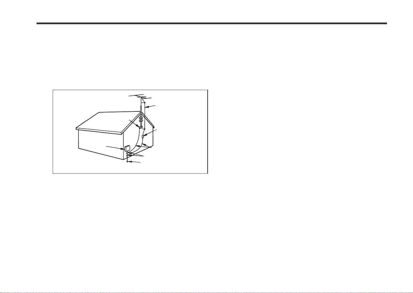
15 Outdoor Antenna Grounding - If an outside antenna or cable system
is connected to the product, be sure the antenna or cable system is
grounded so as to provide some protection against voltage surges and
built-up static charges. Article 810 of the National Electrical Code, ANSI/
NFPA 70, provides information with regard to proper grounding of the
mast and supporting structure, grounding of the lead-in wire to an antenna discharge unit, size of grounding conductors, location of antennadischarge unit, connection to grounding electrodes, and requirements
for the grounding electrode.
Example of antenna grounding as per
National Electrical Code, ANSI/NFPA 70
ANTENNA LEAD IN WIRE
GROUND
CLAMP
ANT EN NA DISCHARGE UNIT
ELECTRIC
SERVICE
EQUIPMENT
NEC - NATIONAL ELECTRICAL CODE
S2898A
(NEC SECTION 810-20)
GROUNDING CONDUCTORS
(NEC SECTION 810-21)
GROUND CLAMPS
POWER SERVICE GROUNDING
ELECTRODE SYSTEM
(NEC ART 250, PART H)
16 Lightning - For added protection for this product during a lightning
storm, or when it is left unattended and unused for long periods of
time, unplug it from the wall outlet and disconnect the antenna or cable
system. This will prevent damage to the product due to lightning and
power-line surges.
17 Power Lines - An outside antenna system should not be located in the
vicinity of overhead power lines or other electric light or power circuits,
or where it can fall into such power lines or circuits. When installing an
outside antenna system, extreme care should be taken to keep from
touching such power lines or circuits as contact with them might be
fatal.
18
Overloading - Do not overload wall outlets, extension cords, or integral
convenience receptacles as this can result in a risk of fire or electric shock.
19 Object and Liquid Entry - Never push objects of any kind into this
product through openings as they may touch dangerous voltage points
or short-out parts that could result in a fire or electric shock. Never spill
liquid of any kind on the product.
20 Servicing - Do not attempt to service this product yourself as opening
or removing covers may expose you to dangerous voltage or other
hazards. Refer all servicing to qualified service personnel.
21 Damage Requiring Service - Unplug this product from the wall outlet
and refer servicing to qualified service personnel under the following
conditions:
a)When the power-supply cord or plug is damaged,
b)If liquid has been spilled, or objects have fallen into the product,
c)If the product has been exposed to rain or water,
d)If the product does not operate normally by following the operating
instructions. Adjust only those controls that are covered by the operating instructions as an improper adjustment of other controls may
result in damage and will often require extensive work by a qualified
technician to restore the product to its normal operation,
e)If the product has been dropped or damaged in any way, and
f) When the product exhibits a distinct change in performance - this
indicates a need for service.
22 Replacement Parts - When replacement parts are required, be sure
the service technician has used replacement parts specified by the
manufacturer or have the same characteristics as the original part.
Unauthorized substitutions may result in fire, electric shock, or other
hazards.
23 Safety Check - Upon completion of any service or repairs to this prod-
uct, ask the service technician to perform safety checks to determine
that the product is in proper operating condition.
24 Wall or Ceiling Mounting - The product should be mounted to a wall
or ceiling only as recommended by the manufacturer.
25 Heat - The product should be situated away from heat sources such
as radiators, heat registers, stoves, or other products (including amplifiers) that produce heat.
0109
iii
Page 5
SPECIAL NOTES
REMARQUES SPÉCIALES
"DTS" and "DTS Digital Surround" are registered trademarks of Digital
Theater Systems, Inc.
"DTS" et "DTS Digital Surround" sont des marques déposées de Digital
Theater Systems, Inc.
Manufactured unde r license fro m Dolby Labo ratories. "D olby", "Pro L ogic"
and the double-D symbol are trademarks of Dolby Laboratories.
Fabriqué sous licence de Dolby Laboratories. "Dolby", "Pro Logic" et le
symbole double D sont des marques de commerce de Dolby Laboratories.
NOTE
Licensed under one or more of U.S. Pat. 4,972,484, 5,214,678,
5,323,396, 5,530,655, 5,539,829, 5,544,247, 5,606,618, 5,610,985,
5,740,317, 5,777,992, 5,878,080 or 5,960,037.
ENERGY STAR® Program Information
Products that have earned the
ENERGY STAR
protect the environment through
superior energy efficiency.
ENERGY STAR® is a U.S. registered mark.
®
are designed to
0312
iv
Page 6

SD-HX500
ENGLISH
ENGLISH
Contents
General Information
! G en e ra l Informat i o n
Accessories . . . . . . . . . . . . . . . . . . . . . . . . . . . . . . . . . . . . . . . . . . . . . . . . . . . . . . . 2
Precautions . . . . . . . . . . . . . . . . . . . . . . . . . . . . . . . . . . . . . . . . . . . . . . . . . . . . . . . 3
Controls and indicators . . . . . . . . . . . . . . . . . . . . . . . . . . . . . . . . . . . . . . . . . . 4 - 8
Description of discs . . . . . . . . . . . . . . . . . . . . . . . . . . . . . . . . . . . . . . . . . . . . .9, 10
! Preparation for Use
System installation . . . . . . . . . . . . . . . . . . . . . . . . . . . . . . . . . . . . . . . . . . . . . . . . 11
System connections . . . . . . . . . . . . . . . . . . . . . . . . . . . . . . . . . . . . . . . . . . . . . . . 12
Speaker connection . . . . . . . . . . . . . . . . . . . . . . . . . . . . . . . . . . . . . . . . . . . .13, 14
Antenna connection . . . . . . . . . . . . . . . . . . . . . . . . . . . . . . . . . . . . . . . . . . . . . . .14
TV connect io n . . . . . . . . . . . . . . . . . . . . . . . . . . . . . . . . . . . . . . . . . . . . . . . . . . . . 15
Remote control . . . . . . . . . . . . . . . . . . . . . . . . . . . . . . . . . . . . . . . . . . . . . . . . . . .16
AC powe r con ne c tion . . . . . . . . . . . . . . . . . . . . . . . . . . . . . . . . . . . . . . . . . . . . . . 16
Setting the clock . . . . . . . . . . . . . . . . . . . . . . . . . . . . . . . . . . . . . . . . . . . . . . . . . .17
General control . . . . . . . . . . . . . . . . . . . . . . . . . . . . . . . . . . . . . . . . . . . . . . . . . . . 18
! DVD Operation
Playing a disc . . . . . . . . . . . . . . . . . . . . . . . . . . . . . . . . . . . . . . . . . . . . . . . . . 19, 20
Basic operation
To locate the beginning of a chapter (track) (skip) . . . . . . . . . . . . . . . . . . . . . . 21
Fast forward/Fast reverse (search) . . . . . . . . . . . . . . . . . . . . . . . . . . . . . . . . . . .21
- Contents -
To start playback from the desired point (direct play ) . . . . . . . . . . . . . . . . . . . . 22
Useful operation
To play in the desired order (programmed play) . . . . . . . . . . . . . . . . . . . . . . . . 23
To play repe a tedly (repeat play) . . . . . . . . . . . . . . . . . . . . . . . . . . . . . . . . . . . . . . 24
To play the contents between the specified points repeatedly (A-B repeat) . . 24
Still picture/Frame advance . . . . . . . . . . . . . . . . . . . . . . . . . . . . . . . . . . . . . . . . . 25
Slow-motion play . . . . . . . . . . . . . . . . . . . . . . . . . . . . . . . . . . . . . . . . . . . . . . . . .25
Resume play . . . . . . . . . . . . . . . . . . . . . . . . . . . . . . . . . . . . . . . . . . . . . . . . . . . . . 25
To change the angle . . . . . . . . . . . . . . . . . . . . . . . . . . . . . . . . . . . . . . . . . . . . . . . 26
To zoom images (zoom) . . . . . . . . . . . . . . . . . . . . . . . . . . . . . . . . . . . . . . . . . . . . 26
To select a title from the top menu of the disc . . . . . . . . . . . . . . . . . . . . . . . . . . 27
To sele c t a su btitle or aud io language from th e di s c m e nu . . . . . . . . . . . . . . . 27
To change the subti t l e la nguage . . . . . . . . . . . . . . . . . . . . . . . . . . . . . . . . . . . . . 27
To change the audio language (audio output) . . . . . . . . . . . . . . . . . . . . . . . . . . 28
Page
Various settings
Page
Brightening the image (Gamma correction) . . . . . . . . . . . . . . . . . . . . . . . . . . . . 28
Sharpening the image (Supe r pic ture) . . . . . . . . . . . . . . . . . . . . . . . . . . . . . . . . 28
To change the display on TV screen . . . . . . . . . . . . . . . . . . . . . . . . . . . . . . . . . . 29
To change the display on the unit . . . . . . . . . . . . . . . . . . . . . . . . . . . . . . . . . . . . 29
Switching elapsed time . . . . . . . . . . . . . . . . . . . . . . . . . . . . . . . . . . . . . . . . . . . . 30
Switching playing time . . . . . . . . . . . . . . . . . . . . . . . . . . . . . . . . . . . . . . . . . . . . . 30
To change the setting on the playb ack control screen . . . . . . . . . . . . . . . . . . . 30
Playing a DVD-Audio disc . . . . . . . . . . . . . . . . . . . . . . . . . . . . . . . . . . . . . . . . . . . 31
! SACD and CD Operation
Playing an SACD disc
Playing hy brid SACD sound . . . . . . . . . . . . . . . . . . . . . . . . . . . . . . . . . . . . . . . . 32
To play in random order (random play) . . . . . . . . . . . . . . . . . . . . . . . . . . . . . . . . 33
Playing an MP3 disc . . . . . . . . . . . . . . . . . . . . . . . . . . . . . . . . . . . . . . . . . . . . . . . 34
! Radio Operation
Listening to the radio . . . . . . . . . . . . . . . . . . . . . . . . . . . . . . . . . . . . . . . . . . . . . . 35
Listening to the memorized station . . . . . . . . . . . . . . . . . . . . . . . . . . . . . . . 36, 37
! Advanced Features
Enjoying surround sound (sound mode) . . . . . . . . . . . . . . . . . . . . . . . . . . 38 - 41
Changing the initial setting of DVD . . . . . . . . . . . . . . . . . . . . . . . . . . . . . . . 42 - 45
Changing the default settings of the amplifier . . . . . . . . . . . . . . . . . . . . . . 46 - 49
Timer playback . . . . . . . . . . . . . . . . . . . . . . . . . . . . . . . . . . . . . . . . . . . . . . . . . . . 50
Setting the timer. . . . . . . . . . . . . . . . . . . . . . . . . . . . . . . . . . . . . . . . . . . . . . . . 50, 51
Operations after setting the timer . . . . . . . . . . . . . . . . . . . . . . . . . . . . . . . . . . . . 52
Sleep timer . . . . . . . . . . . . . . . . . . . . . . . . . . . . . . . . . . . . . . . . . . . . . . . . . . . . . . . 53
Operating the connecte d TV . . . . . . . . . . . . . . . . . . . . . . . . . . . . . . . . . . . . . 54, 55
Storing volume, surround or amplifier settings . . . . . . . . . . . . . . . . . . . . . . . . . 56
Mounting the unit on the wall . . . . . . . . . . . . . . . . . . . . . . . . . . . . . . . . . . . . 57, 58
Connecting other equipment . . . . . . . . . . . . . . . . . . . . . . . . . . . . . . . . . . . . 59 - 61
! References
Maintenance . . . . . . . . . . . . . . . . . . . . . . . . . . . . . . . . . . . . . . . . . . . . . . . . . . . . . 62
Error indicators and warnings . . . . . . . . . . . . . . . . . . . . . . . . . . . . . . . . . . . . . . . 62
Troubleshooting chart . . . . . . . . . . . . . . . . . . . . . . . . . . . . . . . . . . . . . . . . . . 63, 64
Language code list for disc language . . . . . . . . . . . . . . . . . . . . . . . . . . . . . . . . . 65
Specifications . . . . . . . . . . . . . . . . . . . . . . . . . . . . . . . . . . . . . . . . . . . . . . . . . . . . 66
E-1
Page 7
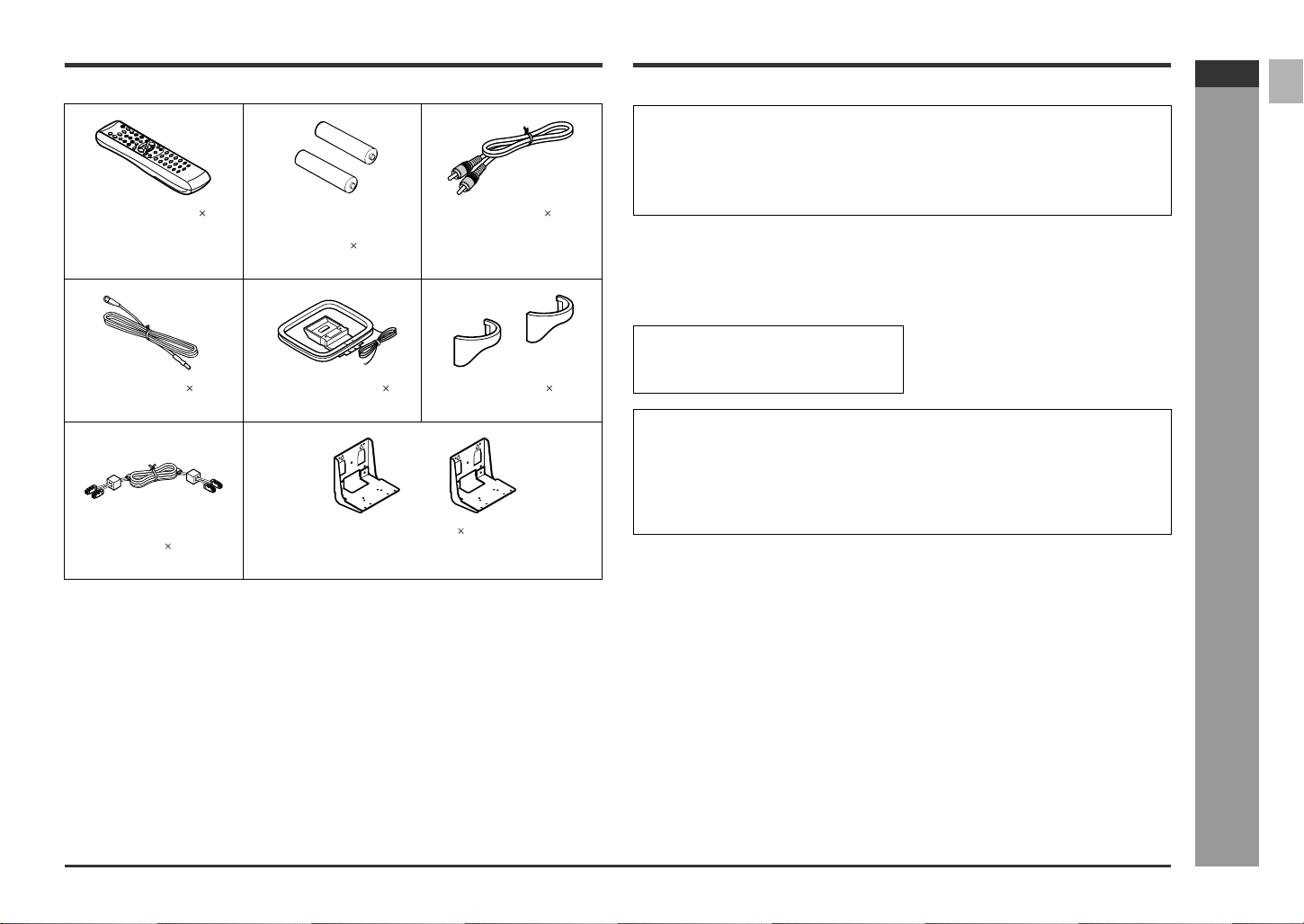
Accessories
Please confirm that the following accessories are included.
Remote control 1 "AA" size battery (UM/
(RRMCGA006AWSA) (UBATU0001AWZZ) (QCNWG0072AWPZ)
FM antenna 1 AM loop antenna 1 Cord Holder 2
(92LFANT1535A) (QANTL0012AWZZ) (LHLDZ1499AWSA)
System connection
cable 1
(QCNWGA004AWPZ) (LANGZA002AWZZ)
SUM-3, R6, HP-7 or
similar) 2
Wall bracket 2
Note:
Only the above accessories are included.
Video cable 1
Copyright Information:
! Unauthorized copying, broadcast, public display, transmission, public perfor-
mance and rental (regardless of whether or not such activities are for profit) of
disc contents are prohibited by law.
! This system is equipped with copy protection technology that causes substantial
degradation of images when the contents of a disc are copied to a video tape.
Copy Protection:
This unit supports Macrovision copy protection.
On DVD discs that include a cop y protection code, if the contents of the DVD disc are
copied using a VCR, the copy protection code prevents the videotape copy from playing normally.
Apparatus Claims of U.S. Patent Nos.
4,631,603, 4,577,216, 4,819,098, and
4,907,093, licensed for limited viewing
uses only.
This product incorporates copyright protection technology that is protected by method claims of certain U.S. patents and other intellectual property rights owned by
Macrovision Corporation and other rights owners.
Use of this copyright protection technology must be authorized by Macrovision Corporation, and is intended for home and other limited viewing uses only unless otherwise authorized by Macrovision Corporation.
Reverse engineering or disassembly is prohibited.
SD-HX500
ENGLISH
- Accessories -
General Information
E-2
Page 8
SD-HX500
ENGLISH
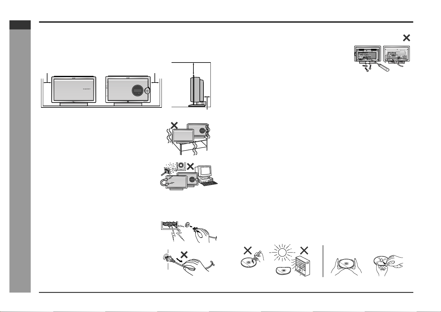
Precautions
! General
" Ensure the unit is positioned in a well-ventilated area with at least the following
amount of free space around the top: 6" (15 cm), sides; 4" (10 cm), and the back:
1-3/8" (3.5 cm).
" Do not remove the outer cover, as this may result
in electric shock. Refer internal service to your local SHARP service facility.
General Information
4" (10 cm) 4" (10 cm)
" Use the unit on a firm, level surface free from vibra-
tion.
" Keep the unit away from direct sunlight, strong mag-
netic fields, excessive dust, humidity and electronic/
electrical equipment (home computers, facsimiles,
etc.) which generate electrical noise.
- Precautions -
" Do not place anything on top of the unit.
" Do not expose the unit to moisture, to temperatures
higher than 140°F (60°C) or to extremely low temperatures.
" If the unit does not work properly, unplug and plug it
in again. Then turn on the unit.
" In case of an electrical storm, unplug the unit for safe-
ty.
" Hold the AC power plug by the head when removing
it from the AC outlet, as pulling the cord can damage
internal wires.
6" (15 cm)
1-3/8" (3.5 cm)
" This unit should only be used within the range of 41°F
- 95°F (5°C - 35°C).
Warning:
The voltage used must be the same as that specified by this unit. Using this product
with a higher voltage other than that specified is dangerous and may result in a fire or
other types of accident, causing damage. SHARP will not be held responsible for any
damage resulting from the use of this unit with a voltage other than that specified.
! Volume control
The sound level at a given volume setting depends on speaker efficiency, location
and various other factors. It is advisable to avoid exposure to high volume levels,
which occurs while turning the unit on with the volume control setting up high, or
while continually listening at high volumes.
! Care of D VD/SACD/CD discs
DVD/SACD/CD discs are fairly resistant to damage, however mistracking can occur
due to an accumulation of dirt on the disc surface. Follow the guidelines below for
maximum enjoyment from your DVD/SACD/CD collection and player.
" Do not write on either side of the disc, particular ly the non-label side from which
signals are read. Do not mark this surface.
" Keep your discs awa y from direct sunlight, heat, and excessive moisture.
" Always hold the DVD/SACD/CDs by the edges. Fingerprints, dirt, or water on the
DVD/SACD/CDs can cause noise or mistracking. If a DVD/SACD/CD is dirty or
does not play properly, clean it with a soft, dry cloth, wiping straight out from the
center, along the radius.
NO
YES
Correct
E-3
Page 9
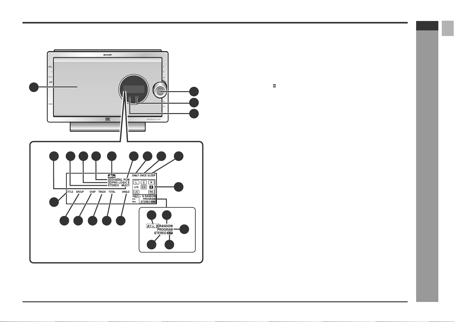
Controls and indicators
1
5
14
6 728
9
1110
12
13
20
SD-HX500
ENGLISH
! Main uni t (front panel)
1.Disc Door . . . . . . . . . . . . . . . . . . . . . . . . . . . . . . . . . . . . . . . . . . . . . . 19
2.Volume Control . . . . . . . . . . . . . . . . . . . . . . . . . . . . . . . . . . . . . . . . . 18
3.Remote Sensor . . . . . . . . . . . . . . . . . . . . . . . . . . . . . . . . . . . . . . . . . 16
4.Timer Set Indicator . . . . . . . . . . . . . . . . . . . . . . . . . . . . . . . . . . . . . . 52
5.SACD/DVD-AUDIO Multi Indicator . . . . . . . . . . . . . . . . . . . . . . . . . . 32
6.SACD/DVD-AUDIO Stereo Indicator . . . . . . . . . . . . . . . . . . . . . . . . .32
7.Dolby Pro Logic Indicator . . . . . . . . . . . . . . . . . . . . . . . . . . . . . . . 3 8
8.Dolby Digital Signal Indicator . . . . . . . . . . . . . . . . . . . . . . . . . . . . . 38
3
4
9.DTS Signal Indicator . . . . . . . . . . . . . . . . . . . . . . . . . . . . . . . . . . . . . 38
10.PCM Signal Indicator . . . . . . . . . . . . . . . . . . . . . . . . . . . . . . . . . . . . 38
11.Daily Timer Indicator . . . . . . . . . . . . . . . . . . . . . . . . . . . . . . . . . . . . .52
12.Once Timer Indicator . . . . . . . . . . . . . . . . . . . . . . . . . . . . . . . . . . . . 52
13.Sleep Indicator . . . . . . . . . . . . . . . . . . . . . . . . . . . . . . . . . . . . . . . . . 53
14.Title Indicator . . . . . . . . . . . . . . . . . . . . . . . . . . . . . . . . . . . . . . . . . . . 29
15.Group Indicator . . . . . . . . . . . . . . . . . . . . . . . . . . . . . . . . . . . . . . . . . 29
16.Chapter Indicator . . . . . . . . . . . . . . . . . . . . . . . . . . . . . . . . . . . . . . . 29
17.Track Indicator . . . . . . . . . . . . . . . . . . . . . . . . . . . . . . . . . . . . . . . . . . 29
18.Total Indicator . . . . . . . . . . . . . . . . . . . . . . . . . . . . . . . . . . . . . . . . . . 30
19.Angle Indicator . . . . . . . . . . . . . . . . . . . . . . . . . . . . . . . . . . . . . . . . . 26
20.Audio Signal/Speaker Indicators . . . . . . . . . . . . . . . . . . . . . . . . . . . 39
21.Repeat/One Track Repeat/A-B Repeat Indicator . . . . . . . . . . . . . . . 24
22.Random Play Indicator . . . . . . . . . . . . . . . . . . . . . . . . . . . . . . . . . . . 33
23.Program Indicator
24.FM Stereo Mode Indicator . . . . . . . . . . . . . . . . . . . . . . . . . . . . . . . . 35
25.FM Stereo Receiving Indicator . . . . . . . . . . . . . . . . . . . . . . . . . . . . . 35
Reference page
- Controls and indicators -
15 16 17 18
19
21 22
24 25
General Information
23
E-4
Page 10
SD-HX500
ENGLISH
General Information
Controls and indicators (continued)
1
2
3
4
5
(Left side) (Right side)
5 6 7
4321
- Controls and indicators -
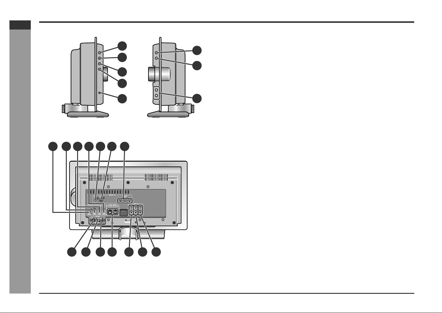
! Main unit (side panel)
6
7
8
1.On/Stand-by Button . . . . . . . . . . . . . . . . . . . . . . . . . . . . . . . . . . .16, 64
2.Disc Door Open/Close Button . . . . . . . . . . . . . . . . . . . . . . . . . . . . . .19
3.Function Button . . . . . . . . . . . . . . . . . . . . . . . . . . . . . . . . . . . . . . . . .60
4.Tuner (Band) Button . . . . . . . . . . . . . . . . . . . . . . . . . . . . . . . . . . . . .35
5.Headphone Jack . . . . . . . . . . . . . . . . . . . . . . . . . . . . . . . . . . . . . . . .59
6.Disc Play Button . . . . . . . . . . . . . . . . . . . . . . . . . . . . . . . . . . . . . . . .19
7.Disc Stop Button . . . . . . . . . . . . . . . . . . . . . . . . . . . . . . . . . . . . .19, 20
8.Chapter (Track) Skip Up and Down Buttons . . . . . . . . . . . . . . .21, 35
Reference page
! Main uni t (rear panel)
1.Coaxial Digital Audio TV Input Jack . . . . . . . . . . . . . . . . . . . . . . . . .59
2.Optical Digital Audio TV Input Jack . . . . . . . . . . . . . . . . . . . . . . . . .59
3.Optical Digital Audio Auxiliary Input Jack . . . . . . . . . . . . . . . . . . . .59
4.Optical Digital Audio Output Jack . . . . . . . . . . . . . . . . . . . . . . . . . .61
5.Video Output Jack . . . . . . . . . . . . . . . . . . . . . . . . . . . . . . . . . . . . . . .15
6.S-video Output Jack . . . . . . . . . . . . . . . . . . . . . . . . . . . . . . . . . . . . .15
7.Component Video Output Jacks . . . . . . . . . . . . . . . . . . . . . . . . . . .15
8.FM 75 Ohm Antenna Jack . . . . . . . . . . . . . . . . . . . . . . . . . . . . . . . . .14
9.Antenna Ground Terminal . . . . . . . . . . . . . . . . . . . . . . . . . . . . . . . . .14
10.AM Antenna Terminal . . . . . . . . . . . . . . . . . . . . . . . . . . . . . . . . . . . .14
11.System Connection Jacks . . . . . . . . . . . . . . . . . . . . . . . . . . . . . . . .12
12.Audio TV Input Jacks . . . . . . . . . . . . . . . . . . . . . . . . . . . . . . . . . . . .59
13.Audio VCR Input Jacks . . . . . . . . . . . . . . . . . . . . . . . . . . . . . . . . . . .59
14.Audio Auxiliary Input Jacks . . . . . . . . . . . . . . . . . . . . . . . . . . . . . . .59
E-5
8 9
11 13
10
12 14
Page 11
SD-HX500
ENGLISH
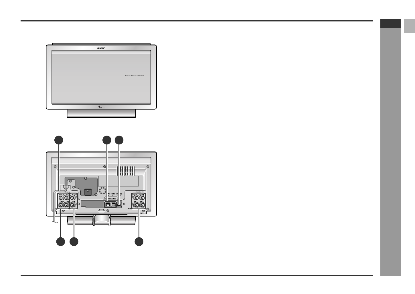
! Amplifier unit
1.AC Power Cord . . . . . . . . . . . . . . . . . . . . . . . . . . . . . . . . . . . . . . . . . 16
2.System Connection Jacks . . . . . . . . . . . . . . . . . . . . . . . . . . . . . . . . 12
3.Subwoofer Pre Output Jack . . . . . . . . . . . . . . . . . . . . . . . . . . . . . . . 61
(Connect a subwoofer with a built-in amplifier.)
4.Front Speaker Terminals . . . . . . . . . . . . . . . . . . . . . . . . . . . . . . . . . . 13
5.Center Speaker Terminals. . . . . . . . . . . . . . . . . . . . . . . . . . . . . . . . . 13
6.Surround Speaker Terminals . . . . . . . . . . . . . . . . . . . . . . . . . . . . . . 1 3
(Front)
1 32
(Rear)
4 5 6
- Controls and indicators -
General Information
E-6
Page 12
SD-HX500
ENGLISH
Controls and indicators (continued)
General Information
2
1
3
4
5
6
7
8
9
10
11
12
13
14
- Controls and indicators -
15
16
17
18
19
20
21
22
23
24
25
26
27
28
29
30
31
32
33
34
35
36
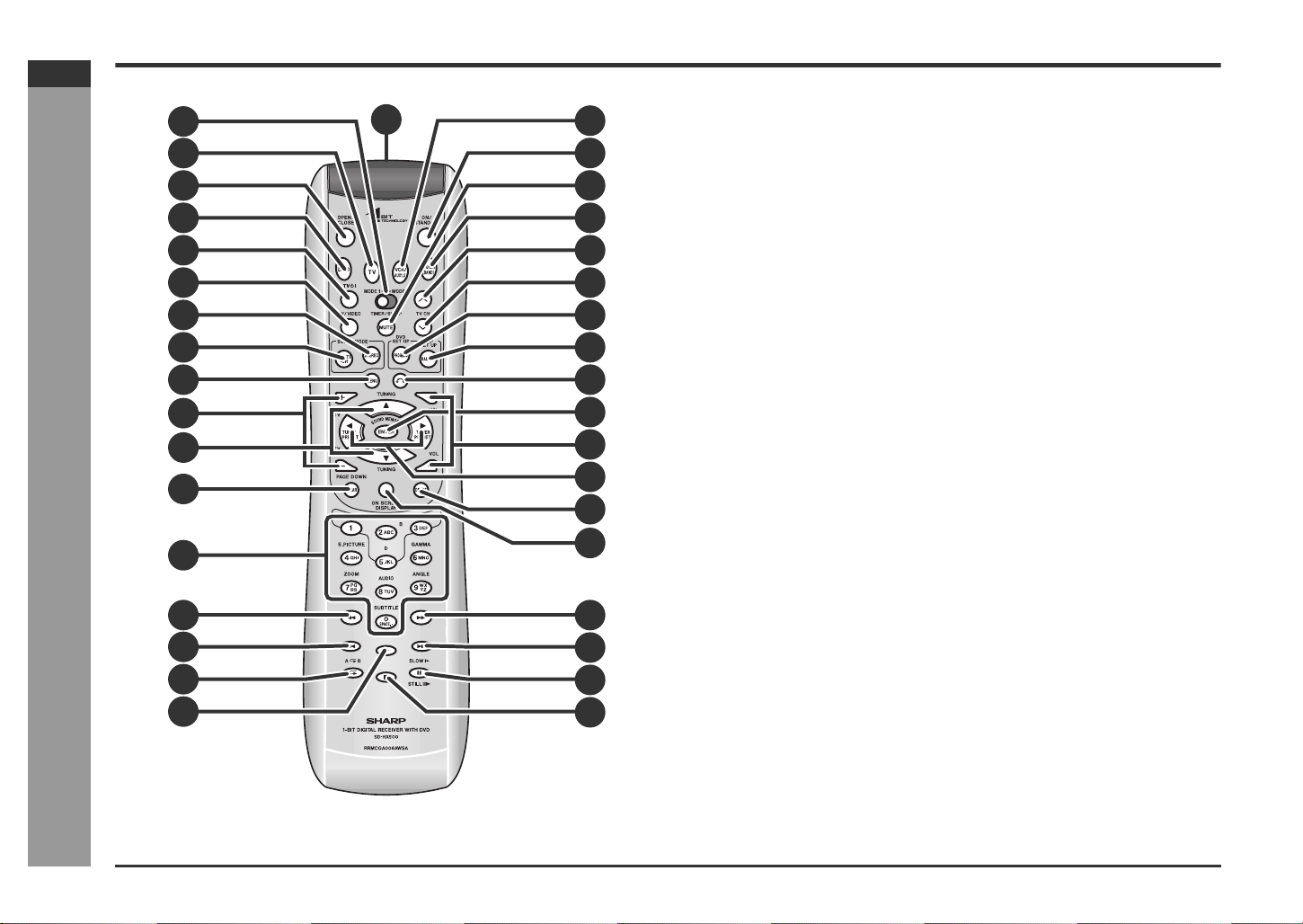
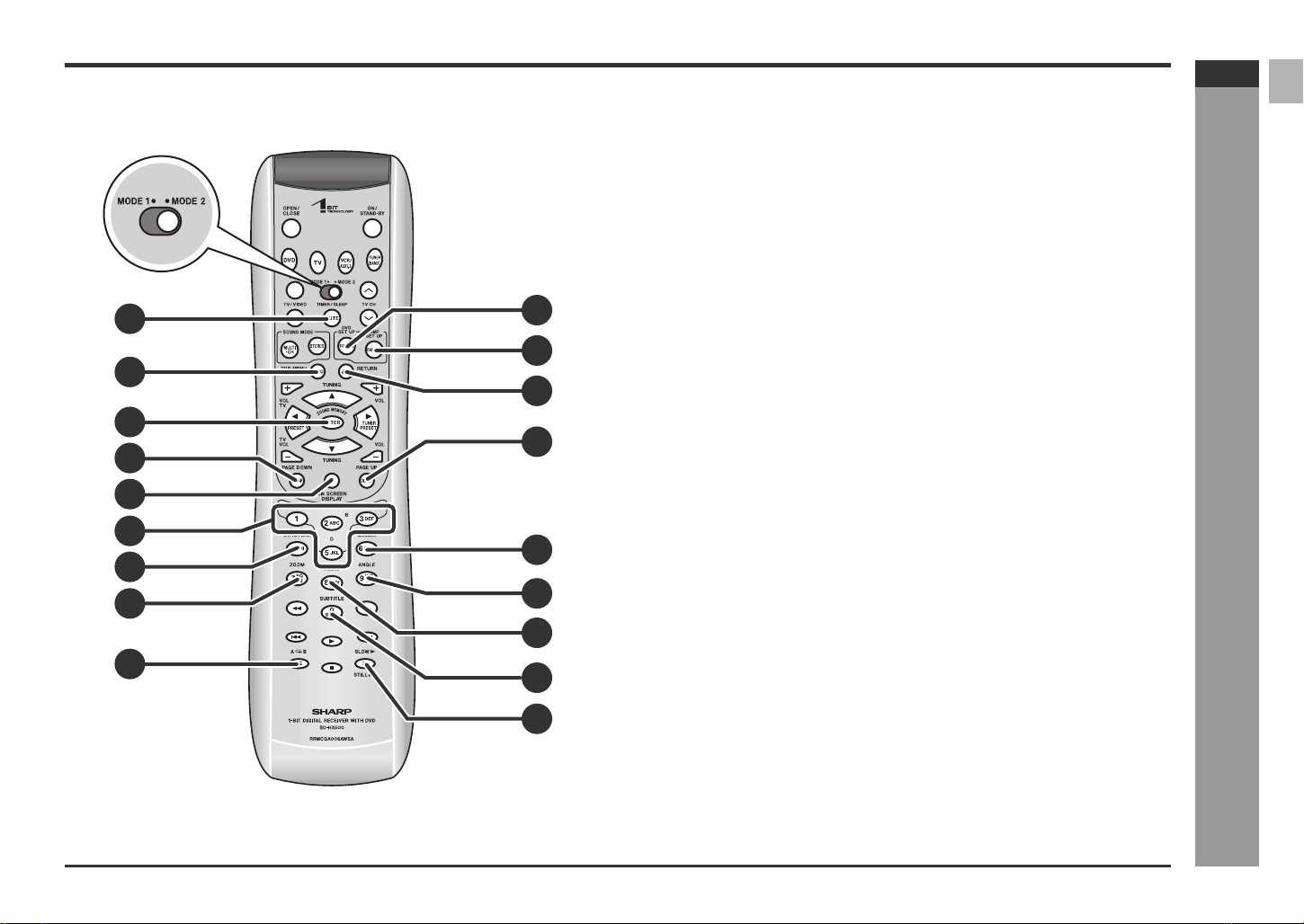
Set the MODE 1/MODE 2 switch to MODE 1 and pres s the following buttons. Available operations change.
Reference page
1.Remote Control Transmitter . . . . . . . . . . . . . . . . . . . . . . . . . . . . . . .16
2.MODE 1/MODE 2 Switch . . . . . . . . . . . . . . . . . . . . . . . . . . . . . . . . . . .8
3.TV Button . . . . . . . . . . . . . . . . . . . . . . . . . . . . . . . . . . . . . . . . . . . . . .60
4.Disc Door Open/Close Button . . . . . . . . . . . . . . . . . . . . . . . . . . . . . .19
5.SACD/DVD Button. . . . . . . . . . . . . . . . . . . . . . . . . . . . . . . . . . . . . . . .19
6.TV On/Stand-by Button . . . . . . . . . . . . . . . . . . . . . . . . . . . . . . . . . . .54
7.TV/Video Select Button . . . . . . . . . . . . . . . . . . . . . . . . . . . . . . . . . . .54
8.Stereo (2 channel) Select Button . . . . . . . . . . . . . . . . . . . . . . . . . . .41
9.Multi Channel Select Button . . . . . . . . . . . . . . . . . . . . . . . . . . . . . . .40
10.Menu Button . . . . . . . . . . . . . . . . . . . . . . . . . . . . . . . . . . . . . . . . . . . .27
11.TV Volume Up and Down Buttons . . . . . . . . . . . . . . . . . . . . . . . . . .54
12.Cursor/Tuning Up and Down Buttons . . . . . . . . . . . . . . . . . . . .17, 35
13.Clear Button . . . . . . . . . . . . . . . . . . . . . . . . . . . . . . . . . . . . . . . . . . . .23
14.Direct Number/Character Input Buttons . . . . . . . . . . . . . . . . . .22, 36
15.Fast Reverse Button . . . . . . . . . . . . . . . . . . . . . . . . . . . . . . . . . . . . .21
16.Chapter (Track) Skip Down Button . . . . . . . . . . . . . . . . . . . . . . . . . .21
17.Repeat Play Button . . . . . . . . . . . . . . . . . . . . . . . . . . . . . . . . . . . . . .24
18.Disc Play Button . . . . . . . . . . . . . . . . . . . . . . . . . . . . . . . . . . . . . . . .19
19.VCR/Auxiliary Button . . . . . . . . . . . . . . . . . . . . . . . . . . . . . . . . . . . . .60
20.On/Stand-by Button . . . . . . . . . . . . . . . . . . . . . . . . . . . . . . . . . . . . . .16
21.Mute Button . . . . . . . . . . . . . . . . . . . . . . . . . . . . . . . . . . . . . . . . . . . .18
22.Tuner (Band) Button . . . . . . . . . . . . . . . . . . . . . . . . . . . . . . . . . . . . .35
23.TV Channel Up Button . . . . . . . . . . . . . . . . . . . . . . . . . . . . . . . . . . . .54
24.TV Channel Down Button . . . . . . . . . . . . . . . . . . . . . . . . . . . . . . . . .54
25.Program Button . . . . . . . . . . . . . . . . . . . . . . . . . . . . . . . . . . . . . . . . .23
26.Random Play Button . . . . . . . . . . . . . . . . . . . . . . . . . . . . . . . . . . . . .33
27.Return Button . . . . . . . . . . . . . . . . . . . . . . . . . . . . . . . . . . . . . . . . . . .22
28.Enter Button . . . . . . . . . . . . . . . . . . . . . . . . . . . . . . . . . . . . . . . . . . . .17
29.Volume Up and Down Buttons . . . . . . . . . . . . . . . . . . . . . . . . . . . . .18
30.Cursor/Preset Up and Down Buttons . . . . . . . . . . . . . . . . . . . . .17, 37
31.Direct Button . . . . . . . . . . . . . . . . . . . . . . . . . . . . . . . . . . . . . . . . . . .22
32.Unit Display Select Button . . . . . . . . . . . . . . . . . . . . . . . . . . . . .18, 29
33.Fast Forward Button . . . . . . . . . . . . . . . . . . . . . . . . . . . . . . . . . . . . .21
34.Chapter (Track) Skip Up Button . . . . . . . . . . . . . . . . . . . . . . . . . . . .21
35.DVD Frame Advance, Disc Pause Button . . . . . . . . . . . . . . . . .20, 25
36.Disc Stop Button . . . . . . . . . . . . . . . . . . . . . . . . . . . . . . . . . . . . .19, 20
! Remote control
E-7
Page 13
SD-HX500
ENGLISH
! Remo te control
Set the MODE 1/MODE 2 switch to MODE 2 and press the following buttons (indicated in blue). Available operations change.
1.Timer/Sleep Button . . . . . . . . . . . . . . . . . . . . . . . . . . . . . . . . . . . 17, 51
2.DVD Top Menu Button . . . . . . . . . . . . . . . . . . . . . . . . . . . . . . . . . . . . 27
3.Sound Memory/Enter Button . . . . . . . . . . . . . . . . . . . . . . . . . . . 27, 56
4.DVD Page Down Button . . . . . . . . . . . . . . . . . . . . . . . . . . . . . . . . . . 31
5.On-Screen Display Button . . . . . . . . . . . . . . . . . . . . . . . . . . . . . . . . 29
6.Sound Pattern Buttons . . . . . . . . . . . . . . . . . . . . . . . . . . . . . . . . . . . 56
1
10
11
2
12
3
13
4
5
6
14
7
8
15
7.DVD Super Picture Button . . . . . . . . . . . . . . . . . . . . . . . . . . . . . . . . 28
8.DVD Zoom Button . . . . . . . . . . . . . . . . . . . . . . . . . . . . . . . . . . . . . . . 26
9.A - B Repeat Button . . . . . . . . . . . . . . . . . . . . . . . . . . . . . . . . . . . . . 24
10.DVD Setup Button . . . . . . . . . . . . . . . . . . . . . . . . . . . . . . . . . . . . 30, 42
11.Amplifier Setup Button . . . . . . . . . . . . . . . . . . . . . . . . . . . . . . . . . . . 46
12.Return Button . . . . . . . . . . . . . . . . . . . . . . . . . . . . . . . . . . . . . . . . . . 30
13.DVD Page Up Button . . . . . . . . . . . . . . . . . . . . . . . . . . . . . . . . . . . . . 31
14.DVD Gamma Button . . . . . . . . . . . . . . . . . . . . . . . . . . . . . . . . . . . . . 28
15.DVD Angle Button . . . . . . . . . . . . . . . . . . . . . . . . . . . . . . . . . . . . . . . 26
16.DVD Audio Language or CD Audio Output Select Button . . . . . . . 28
17.DVD Subtitle Button . . . . . . . . . . . . . . . . . . . . . . . . . . . . . . . . . . . . . 27
18.DVD Slow Button . . . . . . . . . . . . . . . . . . . . . . . . . . . . . . . . . . . . . . . . 25
Notes:
" In "MODE 2", you can use buttons other than the above for the same operations
as in "MODE 1".
" After operations in "MODE 2", switch to "MODE 1".
Reference page
- Controls and indicators -
General Information
16
9
17
18
E-8
Page 14
SD-HX500
ENGLISH
Description of discs
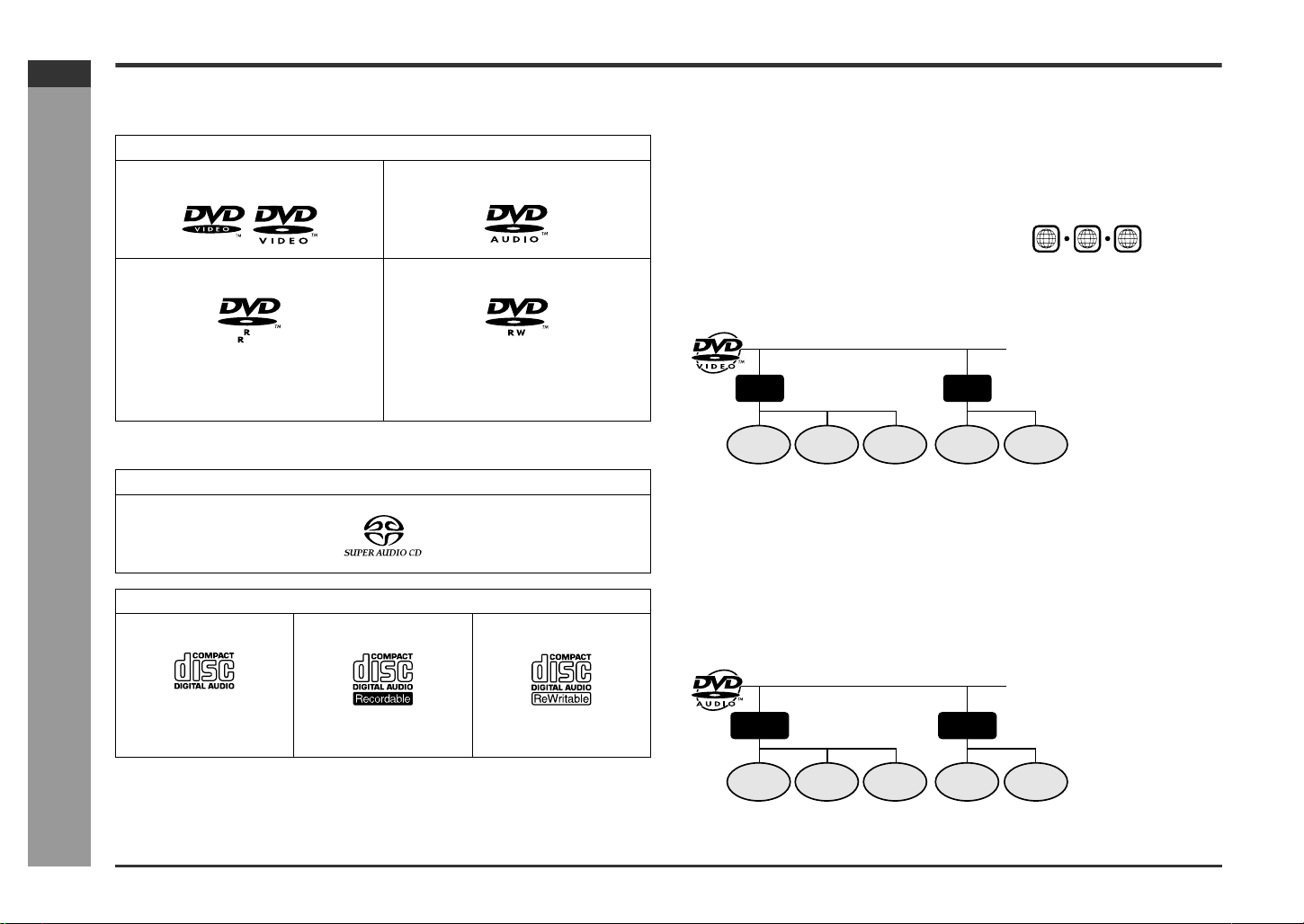
! Types of playable discs
The unit can play back discs bearing any of the following marks:
DVD
DVD-Video Disc for NTSC system DVD-Audio Disc for NTSC system
DVD-R for NTSC system DVD-RW for NTSC system
4.7
Recorded in the video mode (*) Recorded in the video mode (*)
Discs recorded in VR mode (Video Recording format) cannot be played back.
! DVD-Video
A popular type of DVD disc of the same size as a CD, mainly containing video
images.
Region number
DVD discs are programmed with region
numbers indicating countries in which they
can be played. This system can play discs
with region number "1" or "ALL".
Title and chapter
DVD-Video discs ar e divided into "titles" and "chapters". If the disc has more than
one movie on it, each movie is a separate "title". "Chapters" are subdivisions of titles.
Title 1 Title 2
Region number
(playable area number)
1
2
1
ALL
6
General Information
E-9
Some DVD discs may not function as described in the manual. See the disc
jacket for restrictions.
SACD
- Description of discs -
CD
Audio CD Audio CD-R Audio CD-RW
Or CD-R recorded in MP3
format (*)
(*) Some discs may not play properly due to the status of the equipment used for re-
cording, characteristics of the discs, scratches, dirt, or dirty optical pickup lens.
Or CD-RW recorded in
MP3 format (*)
Chapter 1
Chapter 2 Chapter 3 Chapter 1 Chapter 2
! DVD-Audio
Whereas DVD-Videos mainly contain video images, DVD-Audios mostly contain highquality sound data. Its recording capacity is seven times as much as a CD.
Its physical structure is the same as DVD-Videos, but largely differs in data and directory structures. It consists of the audio zone, which is the main par t, and the video
zone, which records video images.
Group and track
A DVD-Audio disc consists of "groups" and "tracks". Groups are equivalent to albums
containing multiple songs. Tracks are the individual songs within a group.
Group 1 Group 2
Track 1
Track 2 Track 3 Track 1 Track 2
Page 15
SD-HX500
ENGLISH
! DVD-R/DVD-RW playback
" You can play DVD-R and DVD-RW discs recorded in the video mode.
" Before playing DVD-R/DVD-RW discs with this unit, finalize them wi th the
equipment used for recording.
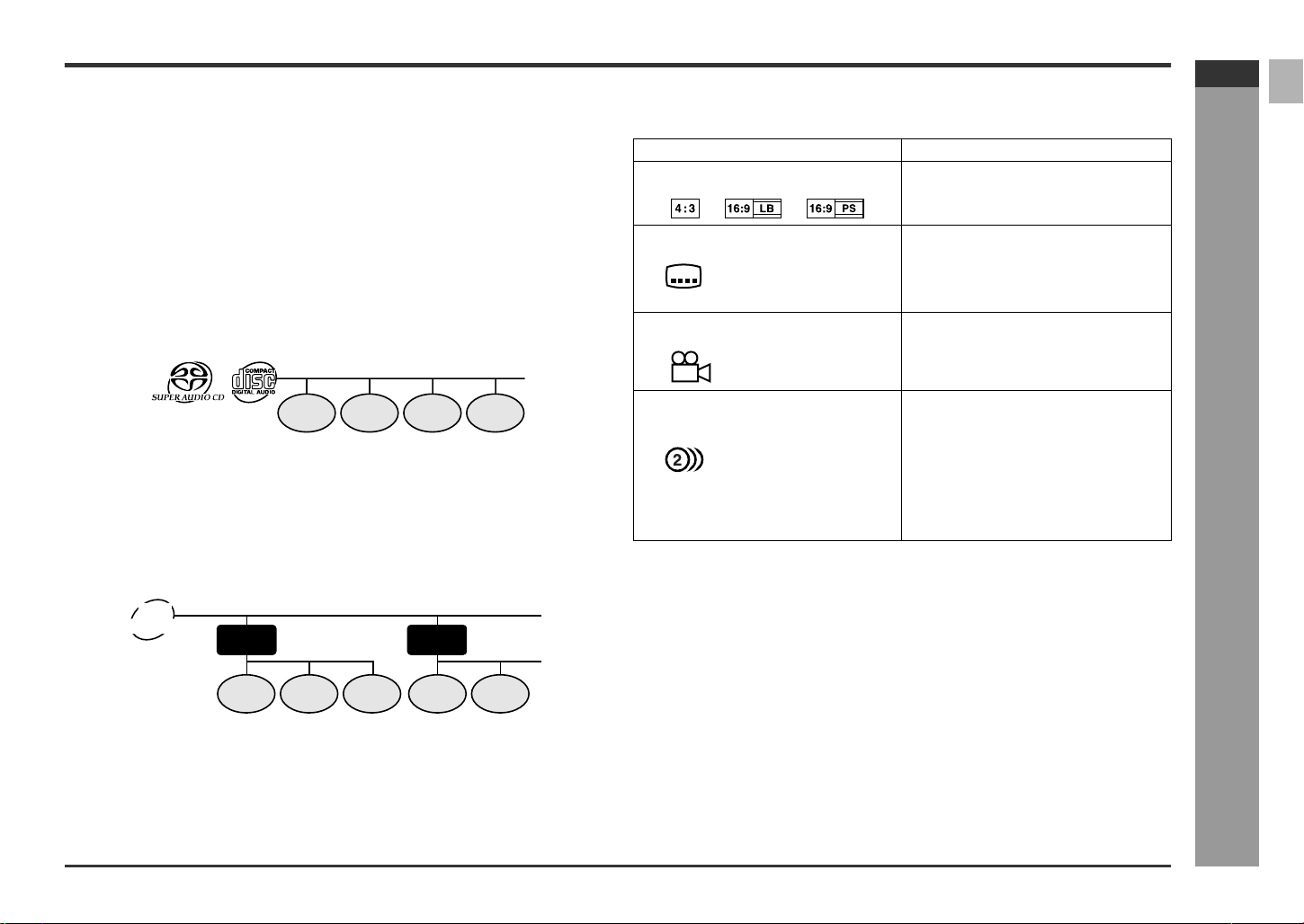
! SACD (Super Audio CD)
An SACD is a high-quality audio disc, capable of recording seven times as much data
as a CD. There are three types of SACD: single layer, dual layer and hybrid.
Hybrid disc contains both SACD and CD structures.
Some SACD discs contain multi channel audio recordings.
Track
SACD and music CD are composed of "tracks". Tracks are equivalent to songs on a
CD.
Track 1 Track 2 Track 3 Track 4
! MP3 format on CD-R/CD-RW
An MP3 file is an audio data compressed in the MPEG 1 audio layer 3 format. MP3
files have the extension ".mp3". (Files with the extension ".mp3" may not play, or
noise may occur during playback if not recorded in the MP3 format.)
Folder and track
MP3 discs consist of "folders" and "tracks".
MP3
disc
Folder 1
Track 1
Folder 2
Track 2 Track 1
Track 2Track 3
! Icons used on DVD discs
Check the icons of the DVD jacket before playing your discs.
Display Description
Format recorded on the DVD To adopt the video format to the connect-
Type of subtitles recorded
2
Example: You can select a subtitle language.
1: English
2: Japanese
Number of camera angles
2
Number of audio tracks an d audio
recording systems
Example: " You can change the audio language.
1: Original <English>
(Dolby Digital 5.1 Surround)
2: Japanese (Dolby Digital 2 ch)
ed TVs ("wide-screen TV" or "4:3 size
TV").
Recorded subtitle languages.
Number of angles recorded on the DVD.
You can view scenes from different an-
gles.
The number of audio tracks and audio recording systems are indicated.
" Audio and recording system vary de-
pending on the DVD. Check them in
the DVD's manual.
! Discs that cannot be played
" DVDs without the region number "1" or
"ALL"
" DVDs with PAL system " Photo CD
" DVDs with SECAM system " CD-ROM
" DVDs with MPEG sound " Discs recorded in special formats, etc.
" DVD-ROM
" DVD-RAM
" The discs above cannot be played at all, or no sound is heard although images
appear on the screen or vice versa.
" Faulty playback may damage the speakers and can have an adverse effect on
your hearing when played at high volume settings.
" This DVD player adopts the NTSC system. Discs that were made in foreign
countries may not be played back. Check the recording system before purchasing discs.
" You cannot play illegally produced discs.
" CDG
" Video CD
- Description of discs -
General Information
E-10
Page 16
SD-HX500
ENGLISH
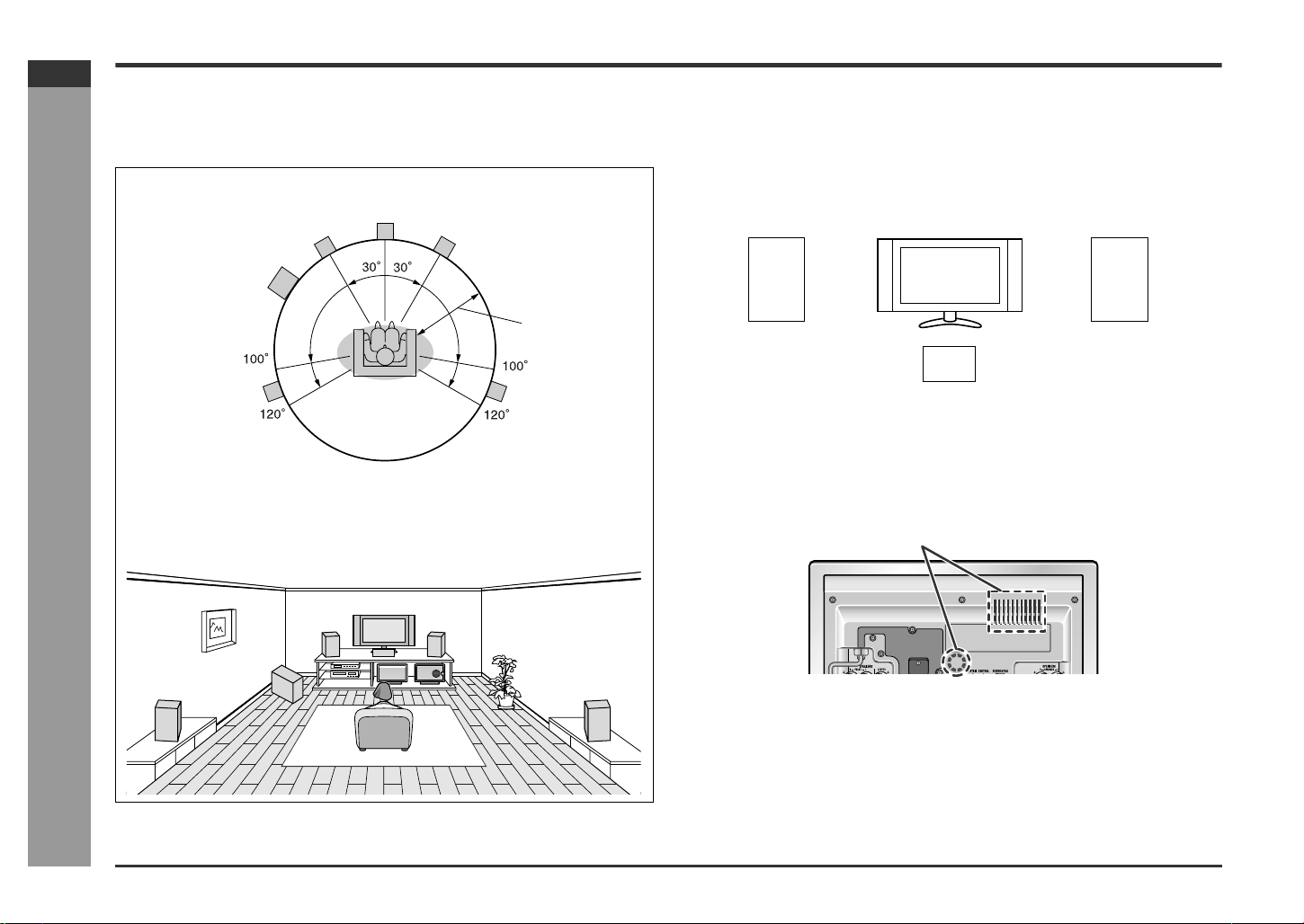
System installation
! Placing the speaker system
The best surround effect will be achieved by placing each speaker at the same
distance from the listening position.
It is recommended to arrange the speakers as shown below.
Front
speaker (left)
Subwoofer
Center
speaker
Front
speaker (right)
Notes:
" Place the TV halfway between the front speakers.
" It is recommended that the center speaker be placed near the television.
" Place the surround speakers at a position just above the height of your ears.
" The subwoofer vibrates while reproducing bass. Place it on a stable, sturdy sur-
face.
" The subwoofer reproduces bass. Place it anywhere you like.
Preparation for Use
Default setting:
6 feet (2 m)
Surround
speaker (left)
Note:
The default distance is set to 6 feet (2 m). If speakers cannot be placed at equal distances, refer to "Speaker delay setting" (see page 47).
Surround
speaker (right)
Installation image:
- System installation -
Front speaker (left) Front speaker (right)
Center speaker
! Cooling fan
This unit is fitted with a cooling fan at the rear for improved cooling. Do not cover the
opening in this section with any obstacles.
Caution:
" The unit will get warm while being used. Do not touch the warm areas of the unit
for prolonged periods to avoid damage to you.
" This unit contains an automatic protection circuit, which protects the unit from
being damaged. All speaker outputs are muted when this circuit is activated.
Should the unit stop operating, first check the speaker terminals for shorted wires,
then press the ON/STA ND-BY button to turn on the unit.
Cooling fan
E-11
Page 17
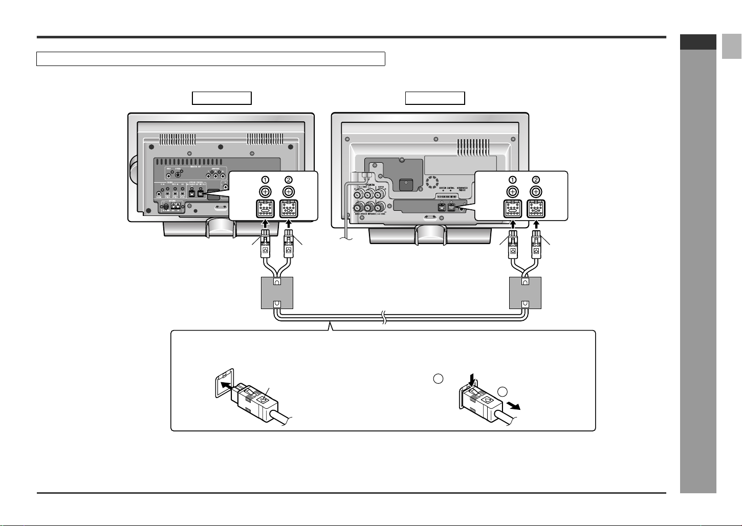
System connections
Make sure to unplug the AC power cord before making this connection.
Connect the main unit and amplifier unit as follows.
Black Blue Black Blue
Tip: blueTip: black Tip: blueTip: black
SD-HX500
ENGLISH
Amplifier unitMain unit
System connection cable
To connect:
Match the colors when connecting the cables.
Insert the cable until it clicks, with the arrow side up.
Arrow
To disconnect:
Pull the cable straight out pressing the plug.
1
Push
2
Unplug
- System connections -
Preparation for Use
E-12
Page 18
SD-HX500
ENGLISH
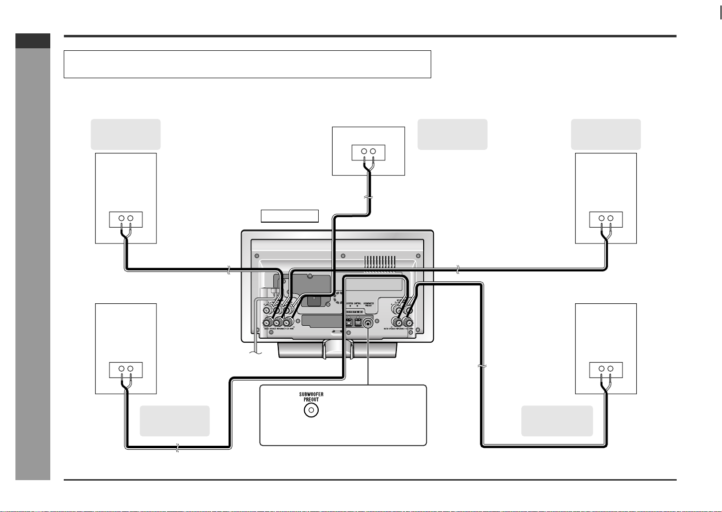
Speaker connection
" Make sure to leave the AC power cord disconnected when connecting the speakers.
" Use a speaker system which has 100 W or more rated power input and 4 - 8 ohm impedance.
See page 11 for placing the speakers.
To enjoy the high-quality sound of DVD-Audio or SACD discs, it is recommended to connect speakers with a wide frequency range.
Preparation for Use
Front speaker
(right)
(not supplied)
Speaker wire
(not supplied)
Center speaker
(not supplied)
Speaker wire
(not supplied)
Amplifier unit
Speaker wire
(not supplied)
Front speaker
(left)
(not supplied)
- Speaker connection -
SHARP TINSKA015AWZZ
Speaker wire
(not supplied)
Speaker wire
(not supplied)
Surround speaker
(right)
(not supplied)
You can connect a commercially available subwoofer with a built-in amplifier (see page 61).
Surround
(left)
(not supplied)
speaker
E-13
Page 19
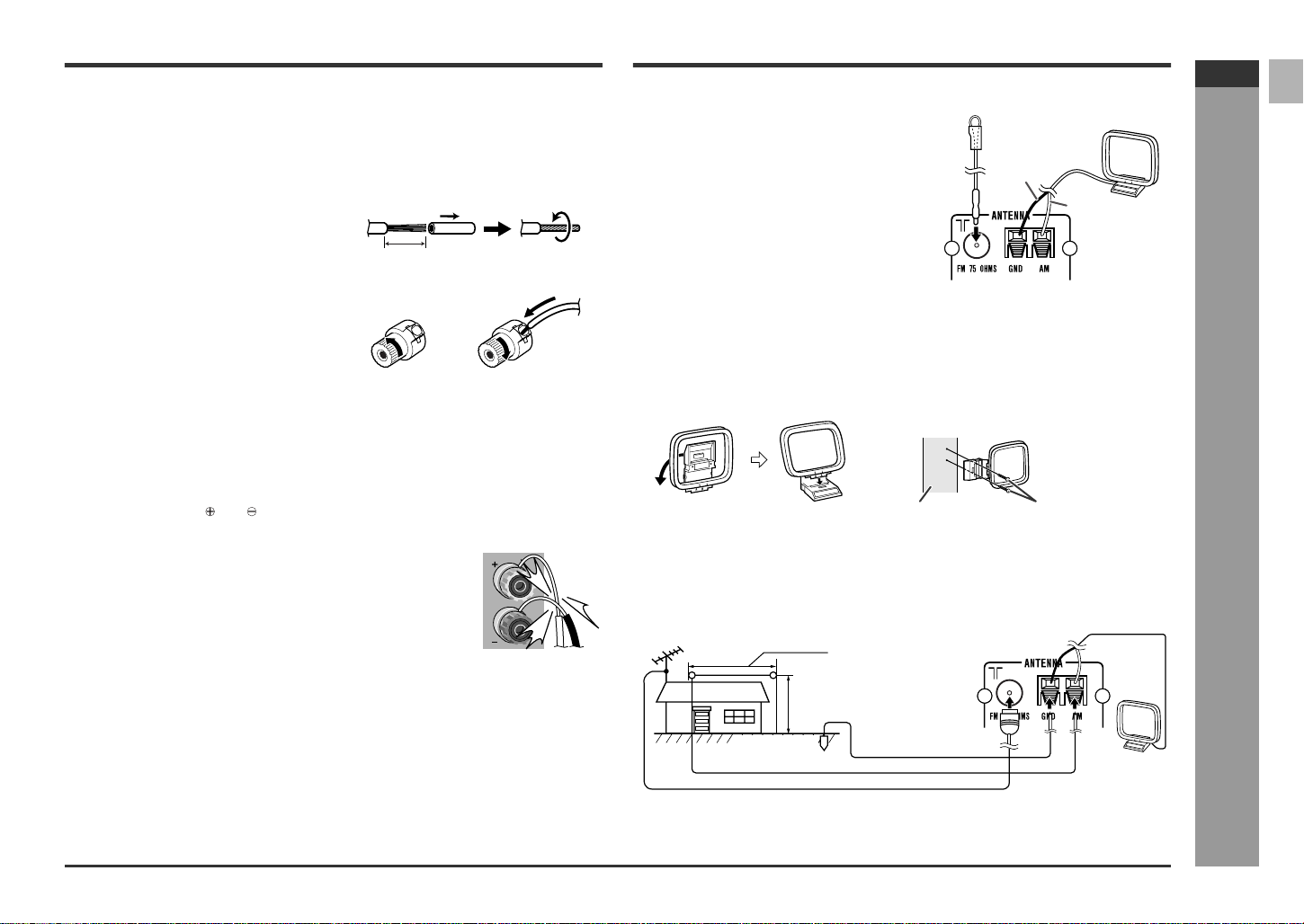
! Connecting speaker wires
Make sure to leave the AC power cord disconnected when connecting the
speakers.
Connect the speaker wires to the speakers first, then to the unit.
When using a speaker wire:
1 Strip the speaker wire about 5/8" (15
mm) and twist the conductors.
Approx. 5/8" (15 mm)
2 Loosen the speaker terminal.
3 Insert the speaker wire and tighten the
thumbscrew.
Antenna connection
Supplied FM antenna:
Connect the FM antenna wire to the FM 75
OHMS jack and position the FM antenna wire in
the direction where the strongest signal can be
received.
FM antenna
Black
Supplied AM loop antenna:
Connect the AM loop antenna wire to the AM
and GND terminals. Position the AM loop antenna for optimum reception. Place the AM loop antenna on a shelf, etc., or attach it to a stand or a
wall with screws (not supplied).
Note:
Placing the antenna on the unit or near the AC power cord may cause noise pickup.
Place the antenna away from the unit for better reception.
White
AM loop
antenna
SD-HX500
ENGLISH
Caution:
" Use a speaker system which has 100 W or more rated power input an d 4 - 8
ohm impedance.
" If the volume is turned up too high with the speakers of less than 4 ohm imped-
ance connected, the protection circuit of the amplifier is activated. No sound is
produced temporarily.
" Do not mistake the and , and right and left terminals of the speaker wires. (The
right speaker is placed on the right when you face the unit.)
" Do not short-circuit the speaker wire. If it happens with the
power on, the protection circuit is activated and the unit is
set to the power stand-by mode. In this case, check that the
speaker wire is connected correctly before turning on the
power again.
Incorrect
" When the center and surround speakers and subwoofer are not connected, set the
speaker size to "C-NO", "S-NO" and "SW-NO". Otherwise, the protection circuit
may be activated and the power is turned off.
Installing the AM loop antenna:
< Assembling > < Attaching to the wall >
Wall Screws (not supplied)
Outdoor FM or AM antenna:
Use an outdoor FM or AM antenna if you require better reception. Consult your
dealer.
When using an outdoor AM antenna, be sure to keep the wire of the AM loop antenna
connected.
Outdoor FM antenna
Ground rod
Outdoor AM antenna
49 feet (15 m)
25 feet (7.5 m )
Ground wire
AM loop
antenna
Preparation for Use
- Speaker connection / Antenna connection -
E-14
Page 20
SD-HX500
ENGLISH
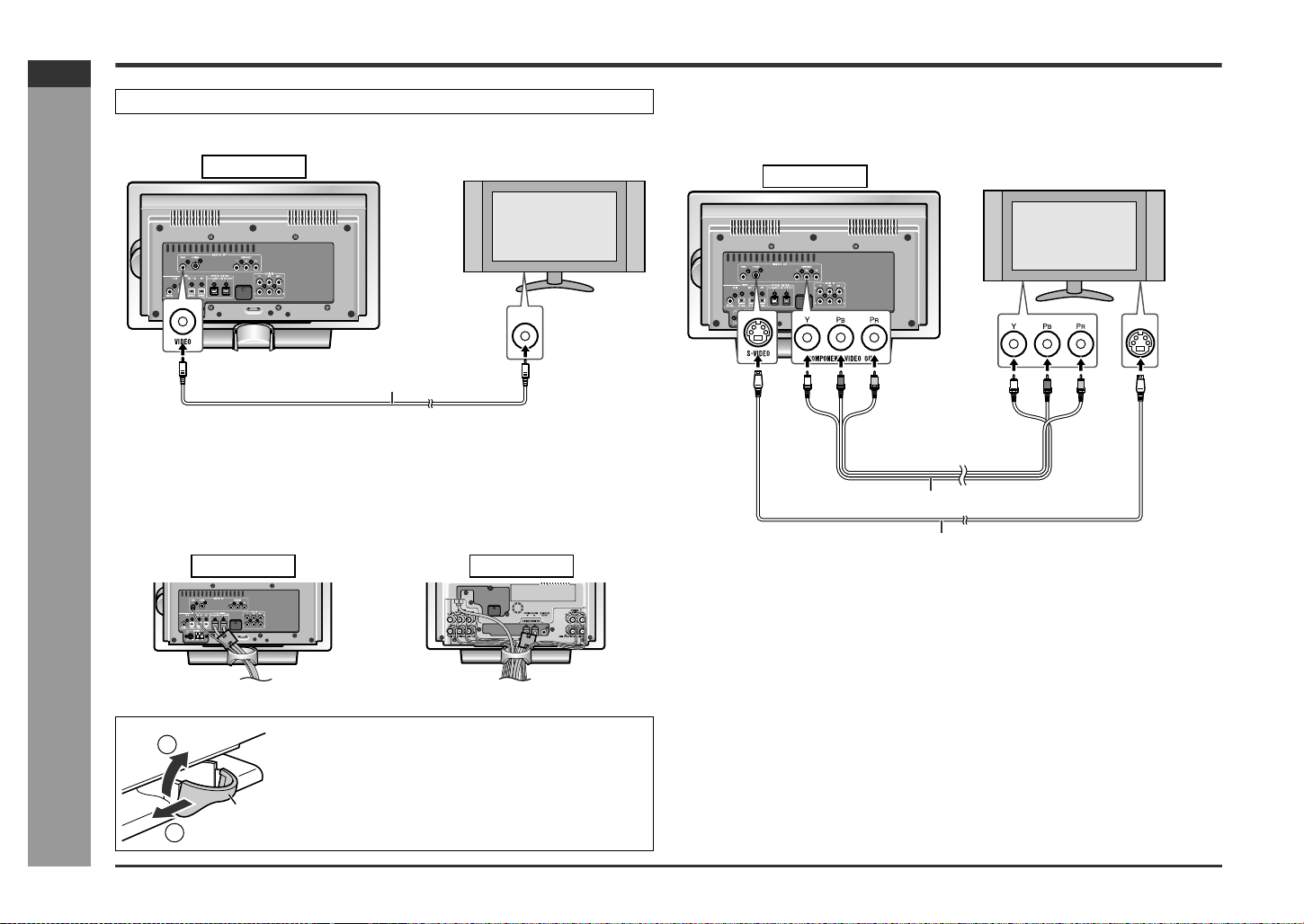
TV connection
Unplug all equipment before making any connections.
Connect a TV with the supplied video cable.
Main unit
TV
If your TV is equipped with an S-video input jack or component video input jacks, purchase an appropriate cable to enjoy higher quality images.
When you use a TV supporting progressive scan, open the initial setting screen and
set "PROGRESSIVE OUT" to "ON" in "TV MODE" (see page 44).
Main unit
TV
Preparation for Use
E-15
Video cable (supplied)
To video
input jack
Notes:
! Change the TV input in accordance with the connected jack.
! Do not connect other equipment between the TV and this unit. If they are con-
nected via a VCR, pictures may be distorted.
! Using the audio cable, you can listen to the TV sound with this unit.
" Positioning cables
Bundle up cables of the main unit and amplifier unit using each cord holder.
- TV connection -
Main unit
Removing cord holders:
2
Cord holder
1
1 Move one side towards outside.
2 Lift up to remove.
Note:
If the image or sound is distorted, remove the AC power
cord and antenna wires from the holder.
Amplifier unit
To component
video input jacks
Component video cable (commercially available)
S-video cable (commercially available)
To S-video
input jack
Notes:
! Change the TV input in accordance with the connected jack.
! Do not connect other equipment between the TV and this unit. If they are con-
nected via a VCR, pictures may be distorted.
! Using the audio cable, you can listen to the TV sound with this unit.
! If your TV has different indications for the component video inputs (Y, CB and CR
or Y, B-Y and P-Y), connect jacks with its matching color.
! Do not connect to a component video input jack designed for the high-vision sys-
tem, which is not DVD-compatible (the images may be distorted or not appear).
! Use a video cable, S-video cable or component video cable to connect the unit to
a TV.
Page 21
Remote control
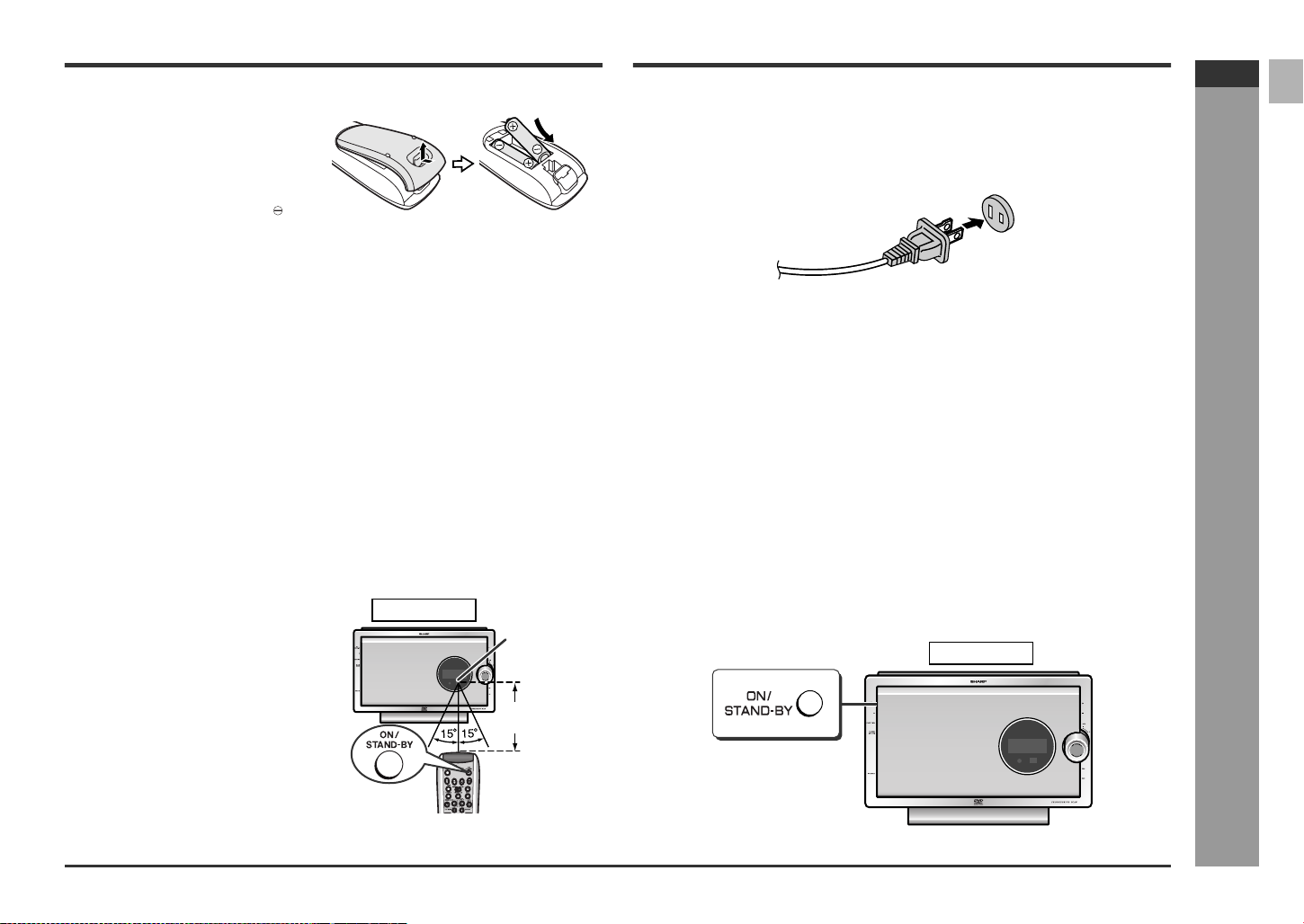
! Battery installation
1 Open the battery cover.
2 Insert the supplied batteries
according to the direction indicated in the battery compartment.
When inserting or removing the batteries, push them toward the battery terminals.
3 Close the cover.
Precautions for battery use:
" Replace all old batteries with new ones at the same time.
" Do not mix old and new batteries.
" Remove the batteries if the unit will not be used for long periods of time. This will
prevent potential damage due to battery leakage.
Caution:
" Do not use rechargeable batteries (nickel-cadmium batter y, etc.).
" Installing the batteries incorrectly may cause the unit to malfunction.
Notes concerning use:
" Replace the batteries if the operating distance is reduced or if the operation
becomes erratic. Purchase 2 "AA" size batteries (UM/SUM-3, R6, HP-7 or similar).
" Periodically clean the transmitter on the remote control and the sensor on the unit
with a soft cloth.
" Exposing the sensor on the unit to strong light may interfere with operation.
Change the lighting or the direction of the unit.
" Keep the remote control away from moisture, heat, shock, and vibrations.
AC power connection
! Conn ectin g the AC power cord
After checking all the connections have been made correctly, plug the AC power cord
of this unit into the AC outlet.
AC outlet
(AC 120 V, 60 Hz)
Note:
Unplug the AC power cord from the AC outlet if the unit will not be in use for a prolonged period of time.
CAUTION:
TO PREVENT ELECTRIC SHOCK, MATCH WIDE BLADE OF PLUG TO
WIDE SLOT, FULLY INSERT.
! To turn the power on
Press the ON/STAND-BY button.
If the power does not turn on, check if the power cords are plugged in properly.
To set the unit to stand-by mode:
Press the ON/STAND-BY button again.
SD-HX500
ENGLISH
! Test of the remote control
Point the remote control directly at the remote sensor on the main unit.
The remote control can be used
within the range shown on the
right.
Press the ON/STAND-BY button. Does
the power turn on? Now, you can enjoy
your system.
Note:
The remote control may not work while the
disc door is open. Move closer to the main
unit, or aim the remote control from different angles.
Main unit
Remote
sensor
8" - 20'
(0.2 m - 6 m)
Notes:
" After the unit enters the power stand-by mode, wait a few seconds to turn on
again.
" You can also use the ON/STAND-BY button on the remote control.
Main unit
Preparation for Use
- Remote control / AC power connection -
E-16
Page 22
SD-HX500
ENGLISH
Preparation for Use
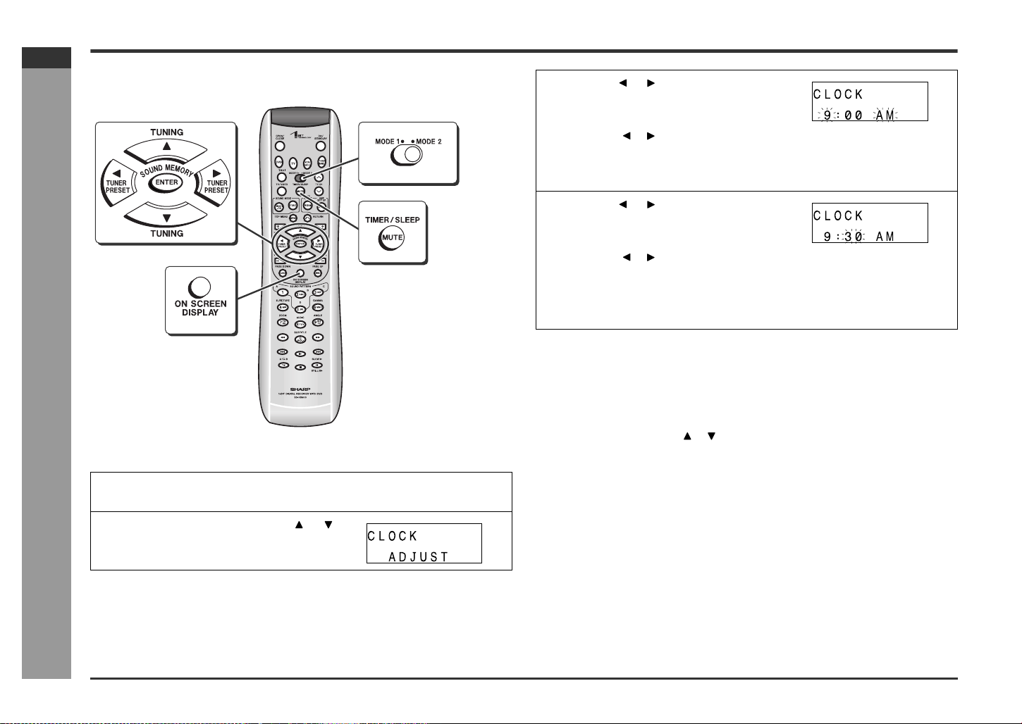
Setting the clock
By setting the unit to the correct time, you can use it not only as a clock but also for
timer playback.
- Setting the clock -
In this example, the clock is set to 9:30 AM.
1
Turn on the power, set the MO DE 1/MO DE 2 switch to MOD E 2 and
press the TIMER/SLEEP button.
2
Within 10 seconds, press the or
button to select "CLOCK ADJUST",
and then press the ENTER button.
3
Press the or button to adjust the
hour and then press the ENTER but-
ton.
" Press the or button once to advance the time by 1 hour. Hold it down to
advance continuously.
" The 12-hour display will appear.
" "AM" will change to "PM" automatically.
4
Press the or button to adjust the
minutes and then press the ENTER
button.
" Press the or button once to advance the time by 1 minute. Hold it down
to advance continuously.
" The hour will not advance even if minutes advance from "59" to "00".
" The clock starts from "0" second (seconds are not displayed).
" The time disappears after approx. 2 seconds.
To confirm the time display:
[When the unit is in the stand-by mode]
Set the MODE 1/MODE 2 switch to MODE 1 and press the DISPLAY button.
The time display will appear for about 5 seconds.
[When the power is on]
Set the MODE 1/MODE 2 switch to MODE 2 and press the TIMER/SLEEP button.
Within 10 seconds, press the or button to select "CLOCK".
The time display will appear for about 10 seconds.
To readj ust the clock:
Perform "Setting the clock" from the beginning.
" In step 2, the time will be displayed.
" Follow steps 3 - 4.
Note:
Unplugging the unit or power failure will clear the clock setting.
Readjust the clock.
E-17
Page 23

General control
Main unit
! Volume control
Main unit operation:
When the VOLUME control is turned clockwise,
the volume will increase. When it is turned counterclockwise, the volume will decrease.
Remote control operation:
Press the VOL + button to increase the volume
and the VOL - button for decreasing.
0 1 2
.....
38 39 40
! Muting
The volume is muted temporarily when set the
MODE 1/MODE 2 switch to MODE 1 and press
the MUTE button.
" Press again to restore the volume.
" The mute status is canceled when you adjust
the volume.
! To change the display brightness (2 levels)
Set the MODE 1/MODE 2 switch to MODE 1 and hold down the DISPLAY b utton for 3
seconds or more.
Each time you press, brightness changes.
Dimmed (*) Brightened
SD-HX500
ENGLISH
- General control -
(*) After approx. 5 seconds of DVD-Video playback, the display dims and the original
brightness returns when you stop playback. The brightness remains unchanged
during playback of other media.
Note:
The blue light on the bottom of the main unit and amplifier unit goes out when the display dims with "DIM ON" or "DIM AUTO".
Preparation for Use
E-18
Page 24

SD-HX500
ENGLISH
DVD Operation
Playing a disc
- Playing a disc -
Main unit
! Playback
" For a wide-screen TV, set the video output to (see page 43).
" Turn on the TV, and switch the input to the "VIDEO 1", "VIDEO 2", etc. according-
ly.
1
Turn on the power and press the
DVD button to set the input to "DVD".
You can also use the button on the main unit.
2
Press the OPEN/CLOSE button to
open the disc door.
3
Insert a disc.
To avoid damage, insert the disc carefully.
4
Press the OPEN/CLOSE button to
close the disc door.
Some discs play automatically.
5
If you cannot start playback in step 4, press the button.
When you press the button with the disc door open, it closes and playback
starts.
Label side
Tab
Please place the
disc with the label
side towards the
door with the
bottom of the disc
resting inside the
door tabs.
DDV
E-19
" You can also use the or button on the main unit.
" To open/close the disc door, press the button on the main unit/remote control.
" The remote control may not work while the disc door is open. Move closer to the
main unit, or aim the remote control from different angles.
Volume control (See page 18.)
Page 25

Operations during disc playback
Action Remote con-
trol
To stop playback
To pause
playback
How to place a disc:
1 Turn the playback side as shown on the right.
2 Place the disc in the tray properly.
" The disc tray supports both 5" (12 cm) and 3"
(8 cm) discs.
" Place the disc carefully to avoid damage.
Removing discs:
Stop playback and remove the disc.
If you turn off the power with the disc door open, the door closes.
Caution:
Do not touch the disc door while it is moving, and be careful not to pinch your fingers.
Main unit Opera tion
When you press once, "RESUME"
appears. Press again to enter the
stop mode.
While "RESUME" appears, press
the button. Playback resumes
from the point where it was
stopped.
(Resume play: See page 25.)
Not available Press during playback.
In the pause mode, press the
button. Playback resumes from the
point where it was paused.
Disc trayPlayback side
Notes:
" Some DVD discs may not function as described in the manual. See the disc jacket
for restrictions.
" During an operation, " " may appear indicating that the operation is disabled by
the disc.
" Some DVD-R/DV D-RW/CD-R/CD-RW may not play properly due to the status of
the disc or equipment used for recording. Change the recording speed or disc. For
more details, see the manual for the equipment.
" When you turn on the power or switch the input to "DVD", initialization starts and
operation is not possible for a few seconds.
" Sound may skip at high volume depending on the disc. In this case, turn down the
volume.
" Do not insert more than one disc. Discs may be damaged.
" A disc with scratches or fingerprints may not play properly. Refer to "Care of DVD/
SACD/CD discs (page 3)" and clean the disc.
" Do not play the discs of special shapes (heart or octagon shaped) as they can be
ejected while rotating and cause injury.
An error message appears on TV or the unit when you try to play the following discs
(see page 62):
" Scratched discs
" Unplayable discs
" The region number is neither 1 nor ALL.
" Discs supporting parental control (*)
(*) Some DVDs support parental control which restricts viewing according to the
age (see page 44).
Icons used in this operation manual
Some functions may not be available depending on discs. The following icons indicate
the discs that can be used in the section.
... DVD-Videos and DVD-Audios.
... Super Audio CDs.
... Audio CDs and CD-R/CD-RW with MP3 recording.
SD-HX500
ENGLISH
- Playing a disc -
DVD Operation
E-20
Page 26

SD-HX500
ENGLISH
Basic operation
! Fast forward/F ast re ver se (sear ch )
You can search the desired point as you play the disc.
1
While a disc is playing, press the or button.
Example: When the button is pressed
! T o locate the beginning of a chapter (trac k)
- Basic operation -
DVD Operation
You can move to other chapter (track) with simple operations.
While a disc is playing, press the or button.
Notes:
" Some discs do not display the chapter (track) and the skip feature is disabled.
" On a DVD, the skip function may not be available across titles (groups).
(skip)
" Press the button to skip to the next chapter (track).
" Press the button to skip to the beginning of the current chapter (track).
Press the button again to skip to the beginning of the previous chapter
(track).
" The same operation can be performed by pressing the or button on
the main unit.
15/
13/
0
00
::01 23
2
Press the or button repeatedly to select a search speed.
C
1
DDV
1 (about 2 times) 2 (about 8 times) 3 (about 32 times)
" The disc is forwarded by the button and reversed by the button.
" The same operation can be performed by holding down the or button
on the main unit for 2 seconds or more.
Press the button to return to normal playback.
Notes:
" On some discs, the search function is disabled.
" The search function is not possible across titles (groups).
" During fast forward, subtitles appear and sound is heard only at the search speed
1 (about 2 times). Sound is not heard on SACD discs.
" Depending on the disc or scene, the search speed may differ from that in this man-
ual.
E-21
Page 27

! To start playback from the desired point
(direct play)
1
During playback, set the MODE 1/MODE 2 switch to MODE 1.
2
Selecting a title of DVD:
Press the DIRECT button.
Selecting a chapter of DVD:
Press the DIRECT button twice.
Selecting a track on SACD/C D discs:
Press the DIRECT button.
3
Within 10 seconds, enter a number with the direct number buttons
(0 - 9) and press the ENTER button.
" To correct the number, enter again.
" To cancel, press the RETURN button.
" Instead of the direct number buttons (0 - 9), you can use the or button.
How to specify:
Example:
To select chapter 12: Press 1, 2, and the ENTER button.
Notes:
" Direct play feature is disabled on some discs.
" Some DVD discs may not display the chapter number.
" During programmed play, this operation is not available .
" On DVD-Audio discs, groups and tracks are played directly instead of titles and
chapters.
TV screen
--
83/5/0
01
::23 40
35/
3/
0
-
-
::23 40
01
Unit display
To play by specifying time (time search):
You can play back from the desired point by specifying the time.
1
During playback, set the MODE 1/MODE 2 switch to MODE 1.
2
DVD:
Press the DIRECT button three
times.
SACD (CD):
Press the DIRECT button twice.
3
Within 10 seconds, enter a number with the direct numb er buttons
(0 - 9) and press the ENTER button.
" To specify 1 hour 23 minutes and 40 seconds, enter "012340".
" To correct the number, enter again.
" To cancel, press the RETURN button.
" When you use the or button instead of the direct number buttons (0 - 9),
press the or to switch among hour, minute and second.
" For DVD-Video discs, specify the elapsed time of the title.
" For DVD-Audio, SACD, CD discs specify the elapsed time of the track.
Notes:
" Time search is not possible across titles (tracks).
" On DVD-Audio discs, time search is not possible across tracks.
" Some discs cannot play from the specified point.
" Time search feature is disabled on some discs.
" During programmed play, this operation is not available.
" For MP3 discs, time search is not available.
" Some discs contain time portions you cannot specify .
TV screen
35/
83/
0
::
-- --
00
Unit display
SD-HX500
ENGLISH
- Basic operation -
DVD Operation
E-22
Page 28

SD-HX500
ENGLISH
DVD Operation
Useful operation
! To play in the desired order (programmed
play)
You can play chapters (tracks) in the desired order within a title (group). 24 chapters
can be programmed (programmed play). Titles (groups) cannot be programmed.
- Useful operation -
1
In the stop mode, set the MODE 1/MODE 2 switch to MODE 1 and
press the PROGRAM button.
Example: DVD
The programming screen is displayed.
To program tracks on SACD/CD discs, go to
step 3.
2
Select a title number with the or
button and press the ENTER button.
The chapter selection screen appears. Cursor
DVD-VIDEO PROGRAM
TITLE
T 1
T 2
DVD-VIDEO PROGRAM
TITLE
T 1
T 2
3
Use the or button to select a
chapter (track) number, and press
the ENTER button.
" The number is saved in the confirmation
area.
" Repeat the operation to program another number.
" To correct, press the button to move the cursor to the confirmation area, se-
lect the chapter (track) number with the or button, and press the CLEAR
button. After deleting the number, press the button to return the cursor to
the selection area.
4
Press the button to start playback.
" The unit stops after playing the chapters (tracks) in the programmed order.
" The programmed contents will be stored until the disc is removed.
DVD-VIDEO PROGRAM
T : 1
C 1
C 2
C 3
C 4
C 5
C 6
Selection area Confirmation
T : 1
1: C 1
2: C
3: C
4: C
5: C
6: C
area
To add numbers to the program:
Repeat steps 1 and 3.
Additional chapter (track) numbers are added immediately after the chapter (track)
already programmed.
To delete all numbers in the program:
1 In the stop mode, press the PROGRAM button.
2 Press the button to move the cursor to the confirmation area.
3 Press the CLEAR button for 4 seconds or more.
To cancel the operation:
Press the PROGRAM button.
To repeat the programmed play:
Press the PROGRAM button, and then press the button.
Programmed play is canceled when playback stops.
Notes:
" Programming cannot be performed while paused or in the playback mode.
" Programmed play is prohibited on some discs.
" Chapters in other titles cannot be programmed together.
" For programmed play on DVD-Audio discs, select groups or tracks.
" For an MP3 disc, programmed play is not available.
E-23
Page 29

! To play repeatedly (repeat play)
You can play a chapter (track) or a title (group) repeatedly by specifying it during playback.
1
During playback, set the MODE 1/MODE 2 switch to MODE 1 and
press the button.
TV screen Unit display
C
08
Each time the button is pressed, the repeat play mode changes in the following
order.
The repeat play mode changes as follows on DVD:
C
T
No display
The repeat play mode changes as follows on SACD/CD:
T
No display
On DVD-Audio discs, the mode switches as follows: T (track), G (group), no
display (normal playback).
2
To return to normal playback, press the button repeatedly to select "NORMAL".
Caution:
After performing repeat play, be sure to press the button. Otherwise, the disc will
play continuously.
DDV
No display
No display
Repeat the currently
playing chapter.
Repeat the currently
playing title.
Normal playback.
Repeat the currently
playing track.
Repeat the currently
playing disc.
Normal playback.
Notes:
" On some discs, the repeat play function is disabled.
" To repeat SACD/CD programmed play, perform repeat play during playback.
" If you press the RANDOM button, the current SACD/CD repeat play is canceled
and switched to random play.
" During DVD programmed play, repeat play is not available.
" When you press the button, the current repeat play of DVD is canceled.
! T o pla y the contents between the specified
points repeatedly (A-B repeat)
You can play the desired portion repeatedly by specifying it during playback.
1
During playback, set the MODE 1/MODE 2 switch to MODE 2 and
press the A B button.
TV screen Unit display
AB
08
The start point (A) is created.
2
Press the A B button again to enter the end point (B).
08
A-B repeat starts from the start point (A) to the end point (B).
3
Press the A B button to return to normal playback.
Notes:
" A-B repeat play is disabled on some discs.
" A-B repeat play for DVD-Video is possible only within a title.
" A-B repeat play for DVD-Audio/SACD/CD is possible only within a track.
" Some scenes on DVD may not allow A-B repeat play.
" During programmed play, A-B repeat play is not available.
" When you press the button, the current A-B repeat play is canceled.
" For MP3 discs, A-B repeat play is not available.
" An end point (B) is created when playback of the title (track) ends.
DDV
AB
DDV
SD-HX500
ENGLISH
- Useful operation -
DVD Operation
E-24
Page 30

SD-HX500
ENGLISH
DVD Operation
Useful operation (continued)
! Still picture/Frame advance
You can freeze the image and advance frame by frame.
1
- Useful operation -
During playback, set the MODE 1/MODE 2 switch to MODE 1 and
press the STILL button.
A still picture appears.
2
Press the STILL button during still picture playback.
Each press of the STILL button advances the frame.
3
Press the button to return to normal playback.
Notes:
" Still picture and frame advance features are disabled on some discs.
" Frame advance is not available on DVD-Audio discs (audio part only).
! Slow-motion play
You can slow down the playback speed.
1
During playback, set the MODE 1/
MODE 2 switch to MODE 2 and press
the SLOW button.
2
Press the SLOW button repeatedly to select a playback speed.
00
15/
13/
0
::01 23
1C
1
DDV
1 (about 1/2 times) 2 (about 1/8 times) 3 (about 1/16 times)
3
Press the button to return to normal playback.
Notes:
" On some discs, the slow-motion playback functions are disabled.
" Slow-motion play is not available on DVD-Audio discs (audio part only).
! Resume play
You can resume playback from the point where it was stopped.
1
While the disc is playing, press the
button.
The unit stores the point.
2
To resume playback, press the button.
Play resumes from the point.
00
15/
13/
0
::01 23
To cancel resume play:
Press the button while "RESUME" is displayed.
Notes:
" The resume play feature is disabled on some discs.
" Depending on the disc, playback may resume from slightly before the stopped
position.
" For MP3 discs, resume play is not available.
1C
D
RESUME
DV
E-25
Page 31

! To change the angle
You can change the angle of view when playing a DVD disc that contains scenes
recorded from multiple angles.
1
When "ANGLE" appears on the unit
display during playback, set the
MODE 1/MODE 2 switch to MODE 2
and press the ANGLE button.
2
Use the ANGLE button to select an
angle number.
Each time you press, the angle changes.
Notes:
" Some DVDs prohibit changing the angle.
" The angle number is not displayed if there is no other angle recorded. "XX" is dis-
played instead.
" Refer to the manual of the disc as the operation may vary depending on the disc.
1
2
! To zoom images (zoom)
You can magnify images during playback.
1
In the pause mode or during playback, set the MODE 1/MODE 2
switch to MODE 2 and press the
ZOOM button.
Pressing the button cycles through the zoom settings as follows:
ZOOM: 1 ( 1.2) ZOOM: 2 ( 1.5) ZOOM: 3 ( 2.0) Off (The indicator goes
out.).
2
To shift the view and display the desired part of a zoomed image,
press the , , or button repeatedly.
To return to normal view:
Press the ZOOM button repeatedly to select "Off" (the indicator goes out).
When you cancel the zoom function, you cannot shift the view.
Notes:
" An image may become distorted when zoomed.
" Subtitles cannot be zoomed.
" When the zoom indicator changes from white to red while shifting the image, you
cannot shift it any further.
ZOOM : 1
ZOOM indicator
SD-HX500
ENGLISH
- Useful operation -
DVD Operation
E-26
Page 32

SD-HX500
ENGLISH
Useful operation (continued)
! T o select a subtitle or audio language from
the disc menu
You can s elect the desired subtitle/audio language and sound sy stem (5.1 ch Dolby
Digital or DTS sound) on your DVD if it has a disc menu.
1
In the stop mode or during playback, set the MODE 1/MODE 2
switch to MODE 1 and press the
MENU button.
2
Press the , , or button to select a subtitle/audio language and
press the ENTER button.
You can also use the direct number buttons for some discs.
Notes:
" The procedure shown here provides only general steps. The actual procedure for
using the disc menu depends on the disc you are using. See the disc jacket for
details.
" During programmed play, setting is not possible on the disc menu.
Example
1.Highlights
2.Start Movie
DVD Operation
E-27
! To select a title from the top menu of the
disc
On a DVD with multiple titles, y ou can select a title from the top menu.
1
- Useful operation -
In the stop mode or during playback,
set the MODE 1/MODE 2 switch to
MODE 2 and press the TOP MENU
button.
2
Use the , , , or button to select the title, and then press the
ENTER button.
" The selected title is played.
" You can also use the direct number buttons for some discs.
Notes:
" The procedure shown here provides only general steps. The actual procedure for
using the disc menu depends on the disc you are using. See the disc jacket for
details.
" On DVD-Audio discs, select a group instead of title.
" During programmed play, setting is not possible on the top menu.
Example
21 Drama Action
43 SF Comedy
! To change the subtitle language
You can change the subtitle language or hide subtitles during playback.
1
During playback, set the MODE 1/MODE 2 switch to MODE 2 and
press the SUBTITLE button.
2
Press the SUBTITLE button repeatedly to
select the subtitle language.
" You can select one of the subtitle languages that are recorded on a DVD.
ENGLISH
" To hide subtitles on the screen, press the or button to select "OFF".
Notes:
" The subtitle language on some DVDs may not be changed.
" If no subtitles are recorded on the disc, "XX" is displayed.
" It may take a little time to switch the subtitle language to the selected one.
" When you set the unit to the stand-by mode or replace the disc, settings retur n to
the default.
FRENCH
1
83/0
SPANISH
ENGLISH
Page 33

! To change the audio language (audio out-
put)
During playback, you can change the audio language (audio output).
1
During playback, set the MODE 1/MODE 2 switch to MODE 2 and
press the AUDIO button.
2
Press the AUDIO button repeatedly to select
the audio language (audio output).
Each time you press, audio language (audio output) changes.
Example:
1: Original <English> (Dolby Digital 5.1 Surround)
D
1
2
3
hc15
.
2: Original <English> (DTS 5.1 Surround)
3: Japanese (Dolby Digital 2 ch)
D
hc2
Notes:
" The audio language on some DVDs may not be changed.
" For available audio languages (audio outputs), see the disc jacket.
" When you switch the audio language (audio output) during DVD-Audio playback,
the beginning of the track may return. In this case, it takes longer to switch the language.
" During CD playback, the audio output switches as follows: "L + R", "L", "R".
" When you set the unit to the stand-by mode or replace the disc, settings return to
the default.
" For MP3 discs, you cannot change the audio output.
1 1
D
hc15
.
Various settings
! Brightening the image (Gamma correction)
1
During playback, set the MODE 1/
MODE 2 switch to MODE 2 and
press the GAMMA button to select
"ON".
"ON" and "OFF" will be switched with each press of this button.
2
Within 10 seconds, press the or
button to set the level.
Level Setting Level Setting
OFF Normal ON Brighter
ON Slightly brighter ON A lot brighter
To restore the original brightness:
In step 1, select "OFF".
! Sh arpeni ng the image (Super picture)
1
During playback, set the MODE 1/
MODE 2 switch to MODE 2 and
press the S.PICTURE button to select "ON".
"ON" and "OFF" will be switched with each press of this button.
2
Within 10 seconds, press the or
button to set the level.
G
ON
ON
G
ON
S
ON
S
SD-HX500
ENGLISH
DVD Operation
- Useful operation / Various settings -
Level Setting Level Setting
OFF Normal ON A lot clearer
ON Slightly clearer ON Soft
ON Clearer
To restore the original image quality:
In step 1, select "OFF".
E-28
Page 34

SD-HX500
ENGLISH
DVD Operation
Various settings (continued)
! To change the display on TV screen
- Various settings -
During playback, set the MODE 1/MODE 2 switch to MODE 2 and
press the ON SCREEN button.
Each time you press, the display changes.
Example: DVD
Always displayed Not displayed Displayed for approx. 3
25/
83/
01
0
::23 40
C
DDV
25/
83/
01
seconds
0
::23 40
! To change the display on the unit
During playback, set the MODE 1/MODE 2 switch to MODE 1 and
press the DISPLAY button.
Each time you press, the display changes.
DVD-Video:
Title elapsed time Title/Chapter number Chapter elapsed time
DVD-Audio:
Track elapsed time Group/Track number Group elapsed time
After approx. 2 seconds After approx. 2 seconds
Sampling frequency (low
frequency effects)(*)
(*) Sampling frequency display may differ or may not appear depending on the
disc.
Notes:
" Title/Chapter numbers or elapsed time may not appear depending on the disc.
" The playing time of the disc specified on the jacket, etc. may not include silence
between tracks, and may differ from that displayed on the unit.
" Elapsed time on the display does not indicate the actual time.
C
DDV
" During MP3 playback, total elapsed time does not appear, and elapsed time can-
not be switched.
Sampling frequency (sur-
round)(*)
Sampling frequency (2
channel)(*)
SHARP TINSKA015AWZZ
E-29
Page 35

! Switching elapsed time
During playback, set the MODE 1/MODE 2 switch to MODE 1 and
press the DISPLAY button.
Each time you press, the display changes.
SACD:
Track elapsed time Track number Total elapsed time
CD:
Track elapsed time Total elapsed time
! Switching playing time
In the stop mode (SACD/CD), select a track number with the or
button.
SACD: CD:
Track number Track playing time Track playing time
! To change the setting on the playback con-
trol screen
On the playback control screen, various settings can be changed at the same time.
1
During playback, set the MODE 1/MODE 2 switch to MODE 2 and
press the DVD SET UP button.
2
Press the or button to select the item, and press the ENTER
button.
Example: DVD
1 Title number
2 Chapter number
3 Elapsed playing time
4 Subtitle
5 Angle
6 Audio language
7Gamma
8 Super picture
9 BIT RATE indicator (unchangeable)
3
Press the , , or button to change the setting and press the
ENTER button.
Example: Gamma is selected
1
2
3
4
5
6
7
25/
83/
0
01
::23 40
ENGLISH
2
1
D
1
OFF
G
OFF
OFF
S
OFF
8
D
1
.
G
ON
S
hc15
.
BIT RATE
hc15
BIT RATE
ENTER
DDV
05 10
SELECT
ENTER
05 10
SELECT
ENTER
DDV
Mbps
RETURNENTER
9
Mbps
RETURN
SD-HX500
ENGLISH
- Various settings -
DVD Operation
After approx. 2 seconds
Repeat the operation as instructed.
(The number of repetition depends on the setting item.)
To change other settings, begin from step 2.
4
Press the RETURN button twice.
The setting is memorized and the playback screen reappears.
Notes:
" Some items may not be selected depending on the type of the disc.
" If the RETURN button is pressed while selecting an item or setting, the previ-
ous screen appears.
" On DVD-Audio discs, groups and tracks appear instead of titles and chapters.
E-30
Page 36

SD-HX500
ENGLISH
DVD Operation
Playing a DVD-Audio disc
Some DVD-Audio discs contain still pictures, or grouped tracks called "bonus group".
A 4-digit password may be required to play a bonus group.
- Playing a DVD-Audio disc -
! Switching still pictures on a DVD-Audio
disc
1
Play a DVD-Audio disc (see page 19).
2
During playback, set the MODE 1/MODE 2 switch to MODE 2 and
press the PAGE UP or PAGE DOWN button.
Each time you press, the image switches.
Notes:
" This operation is not available for some still pictures.
" On DVD-Video discs, you can enjoy various sounds by changing the multi channel
mode or stereo mode (see pages 40, 41). On DVD-Audio discs (audio part only),
you cannot change the two modes.
! Playing bonus groups
1
During playback, set the MODE 1/MODE 2 switch to MODE 1 and
press the DIRECT button.
2
Enter a bonus group number with
the direct number buttons (0 - 9) and
press the ENTER button.
RETURN
3
Enter a 4-digit password with the direct number buttons (0 - 9) and
press the ENTER button.
E-31
Notes:
" For a 4-digit password, see the disc jacket, etc.
" On some discs, a password is not required to play bonus groups.
Page 37

Playing an SACD disc
The procedure of the follo wing pla ybac k functions ar e the same as the
DVD operation.
Page
To locate the beginning of a chapter (track) (skip) . . . . . . . . . . . . . . . . . . . . . . .21
Fast forward/Fast reverse (search) . . . . . . . . . . . . . . . . . . . . . . . . . . . . . . . . . . . .21
To start playback from the desired point (direct play) . . . . . . . . . . . . . . . . . . . .22
To play in th e de s i r e d order (programmed play) . . . . . . . . . . . . . . . . . . . . . . . . .23
To play repeatedly (repeat play) . . . . . . . . . . . . . . . . . . . . . . . . . . . . . . . . . . . . . .24
To play the contents between the specified points repeatedly (A-B repeat) . .24
Resume play . . . . . . . . . . . . . . . . . . . . . . . . . . . . . . . . . . . . . . . . . . . . . . . . . . . . . .25
To chang e t he audio language (audi o output) . . . . . . . . . . . . . . . . . . . . . . . . . .28
To chang e t he display on TV s c r e e n . . . . . . . . . . . . . . . . . . . . . . . . . . . . . . . . . .29
Switching el a ps e d t ime . . . . . . . . . . . . . . . . . . . . . . . . . . . . . . . . . . . . . . . . . . . . .30
Switching playing time . . . . . . . . . . . . . . . . . . . . . . . . . . . . . . . . . . . . . . . . . . . . . 3 0
! Playing hybrid SACD sound
On hybrid discs (consisting of an SACD layer and a CD layer), you can select sound
to play.
1
Insert an SACD disc and press the DVD button.
2
In the stop mode, set the MODE 1/
MODE 2 switch to MODE 2 and press
AUDIO button to select the desired
layer.
It takes a few seconds to switch the audio output for reading the disc information.
Example: Playing a multi channel SACD disc
You can switch the audio output if the multi channel and stereo 2 channel systems are supported.
TV screen Unit display
5.1 channel SACD layer
2 channel SACD layer
2 channel CD layer
3
Press the button.
Playback starts.
MULTI
2 ch
C D
Notes:
" For sound types, see the manual for the hybrid disc.
" When you remove the disc, the audio output returns to "MULTI".
" On SACD (CD lay er only)/CD discs, you can enjoy various sounds by changing the
multi channel mode or stereo mode (see pages 40, 41). You cannot change the
two modes for the SACD (SACD la yer).
TV screen
MULTI
SD-HX500
ENGLISH
- Playing an SACD disc -
SACD and CD Operation
E-32
Page 38

SD-HX500
ENGLISH
Playing an SACD disc (continued)
! To play in random order (random play)
The tracks on the disc can be played in random order automatically.
1
While in the stop or playback mode,
set the MODE 1/MODE 2 switch to
MODE 1 and press the RANDOM button.
2
In the stop mode, press the button.
All tracks play in random order.
To cancel random play, press the RANDOM button.
When you press the button, the current random play is canceled.
Notes:
" Random play is not allowed during programmed playback.
" In random play, the unit will select and play tracks automatically. (You cannot select
the order of the tracks.)
" For MP3 discs, random play is not available.
" In random play, press the button to switch to repeat play.
SACD and CD Operation
E-33
- Playing an SACD disc -
Page 39

Playing an MP3 disc
You can play back a CD-R/CD-RW disc with tracks recorded in the MP3 format.
! Se l ecting a folder on an M P 3 d isc
1
Insert an MP3 disc and press the
DVD button.
The folder selection screen appears.
1/ 4
MUSIC1 MUSIC2
MUSIC3 MUSIC4
Cursor Folder
MP 3
2
Select a folder using the , , or button and press ENTER button.
" The track selection screen appears.
" Move the cursor to a folder and press the button. Playback starts from the
first track.
" Press the RETURN button to return to the folder selection screen.
3
Select a t rack usin g the , , o r
button and press the ENTER button.
Playback starts from the track. Track number
MUSIC1
1TRACK01
3TRACK03
MP 3
2TRACK02
4TRACK04
Skipping tracks:
While a disc is playing, press the or button.
Tracks skip within a folder.
Playing repeatedly (Repeat play):
While a disc is playing, press the button.
The mode switches as follows: " T (track)", " (folder)", "no display (normal playback)".
Notes:
" Alternatively, select a track number with the direct number buttons (0 - 9) and
press the ENTER button to play.
" If the cursor is placed on a track (not playing) for 10 seconds or more, it starts to
play.
" Tracks may not play in the recorded order.
" The unit recognizes up to 8 levels in the folder tree, including folders and tracks.
" 256 tracks can be recognized.
" You can also play multi session discs.
" When the first session contains audio tracks in the CD format, the unit recognizes
the disc as a CD and plays only those tracks.
" It may take some time to read a disc depending on the number of files or folder
tree structure.
" Up to 8 characters are displayed for folder or track names. Some characters and
symbols may not appear properly.
" MP3 discs with data recorded at high speed may not play, or noise may occur dur-
ing playback.
" The MP3 functions are not available when you burn MP3 files on a CD-R/CD-RW
disc to create an audio CD. Play the disc as a standard CD.
SD-HX500
ENGLISH
- Playing an MP3 disc -
SACD and CD Operation
E-34
Page 40

SD-HX500
ENGLISH
Radio Operation
Listening to the radio
Main unit
- Listening to the radio -
1
Turn on the power and press the TUNER (BAND) button to set the
input to "FM (AM)".
2
Press the TUNER (BAND) button repeatedly to select the desired
frequency band.
STEREO
FM stereo FM mono AM
3
Press the TUNING ( or ) button to tune in to the desired station.
Manual tuning:
Press the TUNING button as many times as required to tune in to the desired
station.
Auto tuning:
When the TUNING button is pressed for 0.5 seconds or more, scanning will start
automatically and the tuner will stop at the first receivable broadcast station.
! When radio interference occurs, auto scan tuning may stop automatically.
Should this happen, tune in manually.
! Auto scan tuning will skip weak signal stations.
! To stop the auto tuning, press the TUNING button again.
You can also use the TUNER (BAND), or button on the main unit.
To receive an FM stereo transmission:
Press the TUNER (BAND) button to display the "STEREO" indicator.
! " " will appear when an FM broadcast is in stereo.
FM stereo mode indicator
FM stereo receiving indicator
E-35
Volume control (See page 18.)
! If the FM reception is weak, press the TUNER (BAND) button to turn off the "STE-
REO" indicator. The reception changes to mono, and the sound becomes clearer.
After use:
Press the ON/STAND-BY button to enter the power stand-by mode.
Page 41

Listening to the memorized station
You can store AM and FM stations (40 in total) with names (preset tuning).
1
Tune in the desired station and
press the ENTER button.
! For FM stations, stereo and mono modes are memorized.
! Store the stations in memory, in order, starting with preset channel 1.
2
Within 5 seconds, press the TUNER
PRESET ( or ) button to select the
preset channel number.
3
Within 5 seconds, press the ENTER
button to store that station in mem-
ory.
! When a new station is stored in memory,
the station previously memorized will be
erased.
! To save stations without names, press
the RETURN button.
4
Within 10 seconds, press the ENTER button to name stored stations.
The character entry screen opens.
5
Enter a station name using the character input buttons (0 - 9),
CLEAR, and button (see "How to enter characters" on page 37).
6
After entry, press the ENTER button.
! The station is named.
! Repeat steps 1 - 6 to set other stations, or to change a preset station.
SD-HX500
ENGLISH
Preset channel number
Radio Operation
- Listening to the memorized station -
E-36
Page 42

SD-HX500
ENGLISH
Listening to the memorized station (continued)
" How to enter characters
! Use the character input buttons (0 - 9). Press repeatedly to change the character.
! To move the cursor, press the or button.
Character input
button
Available characters
0 SPACE - JKL 5
1MNO 6
ABC 2 PQRS 7
DEF 3 TUV 8
Character input
button
Available characters
To recall a memorized station:
Press the TUNER PRESET ( or ) button to
select the desired station.
To select a preset station with the direct number buttons:
1 Press the corresponding number ("0" - "9").
2 Press the ENTER button.
For example, to choose 28
1 Press the "2" button.
2 Press the "8" button.
3 Press the ENTER button.
! Press buttons within 5 seconds.
! To correct, enter the number again.
To name or rename stored stations:
Start over from step 1.
Preset channel number
Radio Operation
E-37
GHI 4 WXYZ 9
Example: Entering "HIT FM"
1 Press the "4" button twice. (H)
2 Press the cursor ( ) button to move by one character.
3 Press the "4" button three times. (I)
4 Press the "8" button. (T)
- Listening to the memorized station -
5 Press the "0" button twice. ( )
6 Press the "3" button three times. (F)
7 Press the "6" button. (M)
Deleting characters
Select a character with the or button and press the CLEAR button.
Adding characters
Select a character with the or button and enter characters.
The character at the cursor moves right by 1 character.
To erase all the contents of the preset memory:
1 Hold the CLEAR button down for 4 seconds or
more.
2 Within 10 seconds, press the ENTER button.
Note:
The backup function protects the memorized stations for about 10 days should there
be a power failure or the AC power cord disconnection.
To change the display on the main unit:
Set the MODE 1/MODE 2 switch to MODE 1 and press the DISPLAY button.
The display changes about every 4 seconds.
Memory number Station frequency Name (*)
(*) Names do not appear if stations are not named.
Page 43

Enjoying surround sound (sound mode)
This product is equipped with Dolby Digital and DTS decoders. You can enjoy powerful and high-quality surround sound as if you were on the scene.
Dolby Digital
Disc with this trademark
One of the digital audio systems for theatrical use. You can enjoy the stereophonic
effect in the home theater system.
When you set the audio output to Dolby Digital for a disc recorded in Dolby Digital,
the DIGITAL indicator lights up (see page 28).
DTS (Digital Theater Systems)
Dolby Pro Logic reproduces 5. 1 channel surround from 2 channel stereo sound.
Stereo-recorded discs and video tapes
Dolby Pro Logic decodes 2 channel stereo sound from discs, videotapes, etc. to
reproduce 5.1 channel surround sound. You can enjoy a three-dimensional sound
field.
When Dolby Pro Logic is activated, the PRO LOGIC indicator lights up.
A signal recording format without compression
Used in DVD and CD featuring a musical or concert.
SD-HX500
ENGLISH
Dolby Pro Logic
Linear PCM
Disc with this trademark
One of the digital audio systems for theatrical use. As the sound quality is emphasized, you can enjoy the realistic sound effect in the home theater system.
When you set the audio output to DTS for a disc recorded in DTS, the indicator
lights up (see page 28).
Advanced Features
- Enjoying surround sound (sound mode) -
E-38
Page 44

SD-HX500
ENGLISH
Enjoying surround sound (sound mode) (continued)
" Audio signal/Speaker indicators
Audio signal indicators light up for the corresponding audio source, and speaker indicators are illuminated according to signals sent to the speakers.
(3)(4) (6)(5)
(2)(1)
Audio signal indicator
Speaker indicator
Example:
When 2.1 channel audio signals (L, R, LFE) are
received, the audio signal indicators "L", "R" and
"LFE" light up.
The illustration on the right indicates that 2 channel stereo sound (L and R) is reproduced.
(7)
(10) (11)(9)
(8)
(12) (13)
Audio signal/Speaker indicators:
(1) Left Front Speaker Indicator
(2) Left Indicator
(3) Center Indicator
(4) Center Speaker Indicator
(5) Right Indicator
(6) Right Front Speaker Indicator
(7) Low Frequency Effect Indicator
(8) Surround Monaural Signal Indicator
(Lights up when the surround speakers receive monaural signals.)
(9) Left Surround Speaker Indicator
(10) Left Surround Indicator
(11) Subwoof er Indicator
(12) Right Surro und Indicator
(13) Right Surro und Speaker Indicator
Notes:
! You c an switch the audio output when the disc contains sounds of multiple audio
formats (Dolby Digital, DTS, etc.). See page 28.
! Sound may not be produced from the subwoofer depending on the disc.
! You c annot change the multi channel mode or stereo mode on DVD-Audio discs
(audio part only) or SACD discs (SACD layer only), or while listening to the radio.
Advanced Features
- Enjoying surround sound (sound mode) -
E-39
L, R, LFE: Incoming audio
signals
When Dolby Pro Logic is activated
2 channel stereo sound is converted to 5.1 channel surround sound, and all the speaker indicators " " light up.
" " appears when the
speakers are receiving audio
signals.
Page 45

You can enjoy spacious sound recorded in Dolby Digital or DTS.
Also, Dolby Pro Logic allows you to enjoy spacious 2 channel stereo sound.
SD-HX500
ENGLISH
" Listening to sounds in the multi channel
mode (5.1 ch, etc.)
DVD (Dolby Digital or DTS)
While the disc is playing, press the MULTI-CH button.
Example: DTS format
A maximum of 5.1-ch surround sound is
reproduced to provide three-dimensional
effect.
When you press once, the last used setting appears. To change it, press the button
repeatedly within 3 seconds.
Notes:
! You cannot change the multi channel mode or stereo mode on DVD-Audio
discs (audio part only) or SACD discs (SACD layer only), or while listening to
the radio.
! If sound is unpleasant to listen to, change the multi channel mode or stereo mode.
! Settings for the multi channel mode and stereo mode are retained by input (DVD,
TV, VCR, AUX 1 and AUX 2).
STANDARD MOVIE1
MUSIC2
STANDARD: You can enjoy the original sound as it is.
MOVIE1: The bass level is increased for powerful sound effect.
MOVIE2: Dynamic sound is produced with increased bass.
MUSIC1: You can enjoy lively sound by producing the articulate sound.
MUSIC2: You can enjoy crisp, clearer sound.
NIGHT: Soft but powerful sound is achieved even at low volumes.
MOVIE2
MUSIC1NIGHT
Note:
When listening to Dolby Digital or DTS sound, you cannot select "STADIUM" and
"HALL".
Advanced Features
- Enjoying surround sound (sound mode) -
E-40
Page 46

SD-HX500
ENGLISH
Enjoying surround sound (sound mode) (continued)
While the disc is playing, press the MULTI-CH button.
Example: 2-ch stereo sound
Dolby Pro Logic converts 2 channel
stereo sound of CDs, etc. to 5.1 channel.
When you press once, the last used setting appears. To change it, press the button
repeatedly within 3 seconds.
STANDARD: You can enjoy the original sound as it is.
MOVIE1: The bass level is increased for powerful sound effect.
MOVIE2: Dynamic sound is produced with increased bass.
Advanced Features
MUSIC1: You can enjoy lively sound by producing the articulate sound.
MUSIC2: You can enjoy crisp, clearer sound.
- Enjoying surround sound (sound mode) -
NIGHT: Soft but powerful sound is achieved even at low volumes.
STADIUM: You feel like one of the audience in a stadium.
HALL: A concert hall atmosphere is created.
Notes:
! When monaural signals are received in the multi channel mode, only the center
speaker and subwoofer produce sound.
! When you play Dolby Digital or DTS sound with "STADIUM" or "HALL" set, sur-
round is automatically set to "STANDARD".
2 channel stereo sound (CD, VCR, etc.)
STANDARD MOVIE1 MOVIE2 MUSIC1
MUSIC2NIGHTSTADIUMHALL
" Listening to 2 channel stereo sounds
While the disc is playing, press the STEREO button.
Example: DTS format
You can enjoy 2 channel stereo sound.
When you press once, the last used setting appears. To change it, press the button
repeatedly within 3 seconds.
STEREO VIRTUAL
STEREO: You can enjoy the great acoustic effects of the front speakers and
subwoofer.
VIRTUAL: Although the surround speaker does not work, you can enjoy spa-
cious surround effects.
It sounds as if speakers were also placed in .
Notes:
! When the surround mode is set to "STEREO" or "VIRTUAL", the same monaural
sound is reproduced in the both of the right and left channels.
! Some discs are recorded at 96 kHz of sampling frequency. When this type of disc
is played, the sound mode is changed to "STEREO" automatically. The sound
mode cannot be changed during playback.
E-41
Page 47

Changing the initial setting of DVD
A new setting will be retained even if the unit is set to the stand-by mode. If you want
to restore or change the setting, reset it.
1
Press the DVD button, set the MODE
1/MODE 2 switch to MODE 2 and
press the DVD SET UP button.
"OSD LANGUAGE SETUP" menu appears.
When changing the initial setting next time,
the screen in step 3 will appear. If the "DVD
SETUP" menu appears, perform step 3.
2
Press the , , or button to select
a parameter and press the ENTER
button.
Select a language (see page 43).
OSD LANGUAGE SETUP
ENGLISH
ESPAÑOL
FRANÇAIS
ITALIANO
OSD LANGUAGE SETUP
ENGLISH
ESPAÑOL
FRANÇAIS
ITALIANO
SVENSKA
NEDERLANDS
ENTER
ENTER
SVENSKA
NEDERLANDS
SELECT
RETURN
3
Press the or button to select a
setting item and press the ENTER
button.
For setting items, see the table on page 43.
4
Press the , , or button to select a parameter and press the
ENTER button.
To change other settings, begin from step 2.
5
Press the RETURN button twice.
The new setting is memorized.
Notes:
! You cannot display the initial setting screen while a disc is playing.
! The previous screen appears by pressing the RETURN button while selecting
an item or setting.
OSD LANGUAGE SETUP
ENGLISH
ESPAÑOL
FRANÇAIS
ITALIANO
SVENSKA
NEDERLANDS
ENTER
ENTER
SELECT
RETURN
Example: "TV MODE" is selected
3
4:
TV MODE
PROGRESSIVE OUT
DVD-AUDIO
TV MODE
4:3
PS
4:3
LB
16 : 9
TV MODE
4:3
PS
4:3
LB
16 : 9
LB
OFF
AUDIO
SD-HX500
ENGLISH
Advanced Features
- Changing the initial setting of DVD -
ENTER
ENTER
SELECT
RETURN
E-42
Page 48

SD-HX500
ENGLISH
Changing the initial setting of DVD (continued)
Se t t ing Se l e cta b le pa r a mete r s
TV MODE TV MODE
(* indicates initial settings.)
*
Select according to the TV. P. 44
Description Reference
page
PARENTAL PASSWORD Please enter a 4-
LANGUAGE
Advanced Features
- Changing the initial setting of DVD -
LANGUAGE
PROGRESSIVE
OUT
DVD-AUDIO AUDIO*
(Selectable when
a disc is not inserted.)
LEVEL LEVEL 1 - 8
CODE USA*
AUDIO DIGITAL BITSTREAM*
DISC
OSD
AUDIO ENGLISH*
SUB TITLE ENGLISH
MENU EN* Select a language for the disc menu, etc. If the selected language is not available, the display appears
ENGLISH* DEUTSCH Select an OSD (On Screen Display) language for initial settings and operations.
ESPAÑOL
FRANÇAIS SVENSKA
ITALIANO NEDERLANDS
ON
OFF*
VIDEO
digit password.
OFF*
CANADA
D-PCM
SPANISH
OTHER
SPANISH
OTHER
OFF*
If the TV supports progressive scan, select "ON" to enjoy high resolution images. If not, set to "OFF". P. 44
Some DVD-Audio discs contain both DVD-Audio and DVD-Video contents. Select either as default. P. 31
You can set a 4-digit password required to change the "LEVEL" and "CODE" (country code). If you
forget the password, press the button four times.
Restrict viewing by selecting a level. P. 44
Set a country code according to a parental control level of discs. P. 44
Select the audio output according to the external equipment connected to the optical digital audio output jack.
Select a language to play. If the selected language is not available, the disc plays in a default language.
Select a language for subtitles (displayed on the TV screen). If the selected language is not available,
subtitles appear in a default language.
OFF: Select this to hide subtitles.
in a default language.
P. 44
P. 61
P. 45
P. 45
P. 45
E-43
Page 49

" Vi deo format
Indicator Setting
When playing a wide image (16:9) disc,
the left and right sides of the image are
cut (pan scan) to display a natural-looking 4:3 size image.
A wide image disc without pan scan
is played back in letterbox .
A 4:3 disc is played in 4:3.
When playing a wide image (16:9) disc,
black bands are inserted at the top and
bottom and you can enjoy full wide images (16:9) on a 4:3 size TV.
A 4:3 disc is played in 4:3.
A wide image (16:9) is displayed when
playing a wide image (16:9) disc.
! When playing a 4:3 image disc, the image size depends on the
setting of the connected TV.
! If you play back a wide image (16:9) disc with the unit connected
to a 4:3 TV, images appear stretched vertically.
Note:
When playing the disc with a fixed video format, it will not change even if the TV
screen size is changed.
" Progressive scan playback
Connect the unit to a TV supporting pr ogressive scan with a component video cable.
You can enjoy flicker-free images.
Setting Description
ON (Progressive)*1 If the TV supports progressive scan, set to "ON".
OFF (Interlace)*2 If the TV does not support progressive scan, set to
You can enjoy flicker-free images.
"OFF". Images are displayed in the interlaced system.
*1 Progressive
525 scanning lines are drawn in order without interlacing (first field), and then 525
scanning lines are drawn in the same pass on the next field.
*2 Interlace (Interlaced scan)
Following odd-numbered scan lines, even-numbered scan lines (262.5 lines each)
are drawn in 1/60 seconds. This occurs in two separate fields. As a result, a 525line image (frame) is created.
Notes on a non-progressive scan TV
If "PROGRESSIVE OUT" is set to "ON", the TV does not display images. Connect
the supplied video cable, switch the input to video, and set "PROGRESSIVE OUT"
to "OFF".
Compatibility of the progressive scan TV
Some progressive scan TVs are not fully compatible with this product, which may
cause image distortion. In this case, set "PROGRESSIVE OUT" to "OFF".
" Parental setting
Indicator Setting
LEVEL 1 Only DVD software intended for children can be played back.
LEVEL 2 to 7 Only DVD software intended for general use and children can be
LEVEL 8 DVD software of any grade (adult/general/children) can be played
OFF Parental control is canceled.
CODE Country code for parental control
Country code list:
USA
CANADA
JAPAN
GERMANY
FRANCE
UK
ITALY
Notes:
! For the parental setting, enter a 4-digit number (example: 1234), which will be your
password. Enter "1234" from the next time.
! While playing a disc with parental control, the display may appear requesting a
password in order to watch some restricted scenes. In such a case, enter the
password to temporarily change the control level.
played back.
back.
SPAIN
SWISS
SWEDEN
HOLLAND
NORWAY
DENMARK
FINLAND
BELGIUM
HONG KONG
SINGAPORE
THAILAND
MALAYSIA
INDONESIA
TAIWAN
PHILIPPINE
AUSTRALIA
RUSSIA
CHINA
-
-
-
SD-HX500
ENGLISH
Advanced Features
- Changing the initial setting of DVD -
E-44
Page 50

SD-HX500
ENGLISH
Changing the initial setting of DVD (continued)
! Di sc languag e ! Selecting a language for "DISC LAN-
Indicator Setting
AUDIO A language for audio can be set.
SUB TITLE A language for subtitle can be set.
Advanced Features
MENU A language for disc menus can be set.
- Changing the initial setting of DVD -
You can specify a language for dialogues and narration.
English French
Thank you
The subtitle is displayed in a specified language.
English French
Thank you
Menu screens are displayed in a specified language.
Merci
English French
CAST
STAFF
ACTEURS
PERSONNEL
Merci
GUAGE", etc.
Check the code of the language (See the language code list on page 65).
Example: When you select HU (Hungarian)
1
On the initial setting screen, select
"DISC LANGUAGE" (see steps 1 - 3
on page 42), and select "MENU" and
press the ENTER button.
2
Press the or button to select "H"
for the first letter.
3
Press the or button to move the
cursor to the "MENU 2".
4
Press the or button to select "U"
for the second letter.
5
Press the ENTER button.
6
Press the RETURN button twice.
The new setting is memorized.
DISC LANGUAGE
AUDIO
SUB TITLE
MENU
ENTER
DISC LANGUAGE
MENU 1 H
MENU 2 A
DISC LANGUAGE
MENU 1 H
MENU 2 A
DISC LANGUAGE
MENU 1 H
MENU 2 U
SELECT
ENTER
ENGLISH
ENGLISH
ENGLISH
RETURN
SHARP TINSKA015AWZZ
E-45
Page 51

Changing the default settings of the amplifier
Change settings according to the connected speakers.
Speaker size setting (See pages 46, 47.)
Speaker delay setting (See page 47.)
Speaker level setting (See page 48.)
Test tone (See page 48.)
Changing crossover frequency (See page 49.)
Example:
If the right surround speaker is 10 feet (3.3 m) away from the listening position,
change settings as shown below (adjust the SR).
If you press during the
operation, you can go
back one step.
SD-HX500
ENGLISH
CT
FL
SW
SL
Default setting: 6 feet (2 m)
1 In "Speaker delay setting", set the right surround speaker (SR) to 10 feet (3.3 m).
2 In "Speaker level setting", slightly increase the level of the right surround speaker
as it is a little farther than others (see page 48).
3 In "Test tone", check the sound from each speaker (see page 48).
Notes:
" The subwoofer setting applies to a subwoofer connected to SUBWOOFER PRE
OUT.
" You cannot change the default settings while playing SACD/DVD-Audio discs.
FR
SR
FL
SW
SL
CT
10 feet
(3.3 m)
FR
SR
! Speaker size setting
You can change the sizes of the front speakers, center speaker, and surround speakers, or turn on or off the center speaker, surround speakers, or subwoofer.
1
Set the MODE 1/MODE 2 switch to MODE 2 and press the AMP SET
UP button.
2
Within 10 seconds, press the or button to
select "SP SIZE", and press the ENTER but-
ton.
3
Within 10 seconds, press the or button to
select the desired speaker.
The indicators of selected speakers flash.
Advanced Features
- Changing the default settings of the amplifier -
Continued to the next page
E-46
Page 52

SD-HX500
ENGLISH
Advanced Features
Changing the default settings of the amplifier (continued)
4
Within 10 seconds, press the or button to
select their sizes.
To set sizes of other speakers, repeat the operation
from step 3.
5
Press the RETURN button twice.
The setting is complete.
When you select "LARGE", all channel signals are sent to the speaker.
When you select "SMALL", frequencies below the value you set for crossover frequency (see page 49) are sent to the subwoofer.
Speaker type Speaker size
Front speaker (Left, Right) F-LA R GE * Large diameter
F-SMALL Small diameter
Center speaker C-LARGE * Large diameter
C-SMALL Sm all diameter
C-NO OFF
Surround speaker (Left, Right) S-LARGE * Large diameter
S-SMALL Small diameter
S-NO OFF
Subwoofer SW-YES * ON
SW-NO OFF
(*) indicates the default setting.
Notes:
" The speaker size setting is only available for the subwoofer if the input is set to
tuner, or the surround is "STEREO" or "VIRTUAL".
" On some DVD-Audio or SACD discs, the subwoofer may not produce sound even
if the speaker size is set to "SMALL".
" "F-SMALL" and "SW-NO" cannot be combined. If the subwoofer is changed to
"SW-NO" while the front speakers are set to "F-SMALL", they are changed to "F-
- Changing the default settings of the amplifier -
LARGE". When the front speakers are changed to "F-SMALL" while the subwoofer
is set to "SW-NO", it is changed to "SW-YES".
" If "LARGE" is set for a small speaker, malfunction may result. Be sure to set the
speaker size to "SMALL".
" When the center and surround speakers and subwoofer are not connected, set the
speaker size to "C-NO", "S-NO" and "SW-NO". Otherwise, the protection circuit
may be activated and the power is turned off.
! Speaker delay setting
When some of the speakers are at a different distance from the listening point, you
can select the speaker delay to make it seem as though the speaker distances are
the same.
1
Set the MODE 1/MODE 2 switch to MODE 2 and press the AMP SET
UP button.
2
Within 10 seconds, press the or button to
select "SP DELAY", and press the ENTER
button.
3
Within 30 seconds, press the or button to
select the desired speaker.
The indicator of the selected speaker flashes.
4
Within 30 seconds, press the or button to
select the distance.
" You can change the distance in 1 foot (0.3 m) steps.
" To set the distance of other speakers, repeat the op-
eration from step 3.
5
Press the RETURN button twice.
The setting is complete.
Speaker type Delay range Default setting
FL Front speaker (Left) 1 to 29 ft 6 ft (2 m)
CT Center speaker 1 to 29 ft 6 ft (2 m)
FR Front speaker (Right) 1 to 29 ft 6 ft (2 m)
SR Surround speaker (Right) 1 to 29 ft 6 ft (2 m)
SL Sur round speaker (Left) 1 to 29 ft 6 ft (2 m)
SW Subwoofer 1 to 29 ft 6 ft (2 m)
Notes:
" The speaker delay setting is only available for the front speakers and subwoofer if
the input is set to tuner, or the surround is "STEREO" or "VIRTUAL".
" The speaker delay setting is invalid while playing DVD-Audio or SACD discs (valid
for the CD layer of SACD discs).
E-47
Page 53

! Speaker level setting
If sounds from the speakers are uneven, you can equalize them by adjusting the
speaker levels.
1
Set the MODE 1/MODE 2 switch to MODE 2 and press the AMP SET
UP button.
2
Within 10 seconds, press the or button to
select "SP LEVEL", and press the ENTER bu t-
ton.
3
Within 10 seconds, press the or button to
select the desired speaker.
The indicator of the selected speaker flashes.
4
Within 10 seconds, press the or button to
adjust the level.
" You can adjust the level at 1 dB intervals.
" To adjust the levels of other speakers, repeat the op-
eration from step 3.
5
Press the RETURN button twice.
The setting is complete.
Speaker type Level range Default setting
FL Front speaker (Left) - 10 dB to + 10 dB 0 dB
CT Center speaker - 10 dB to + 10 dB 0 dB
FR Front speaker (Right) - 10 dB to + 10 dB 0 dB
SR Surround speaker (Right) - 10 dB to + 10 dB 0 dB
SL Surround speaker (Lef t) - 10 dB to + 10 dB 0 dB
SW Subwoofer - 10 dB to + 10 dB 0 dB
Notes:
" The speaker level setting is only available for the front speakers and subwoofer if
the input is set to tuner, or the surround is "STEREO" or "VIRTUAL".
" If subwoofer sound is distorted, lower the subwoofer level.
! Test tone
You can check each speaker sound by a test tone. Readjust the volume set in
"Speaker lev el setting".
1
Set the MODE 1/MODE 2 switch to MODE 2 and press the AMP SET
UP button.
2
Within 10 seconds, press the or button to
select "TONE", and press the ENTER button.
The test tone will be heard from each speaker, in order, at about 2-second intervals.
FL CT FR
SW SL SR
To adjust speaker levels
While the test tone is heard:
Adjust the level with the or button.
Press the or to select a speaker.
3
Press the RETURN button twice.
The setting is complete.
Notes:
" The test tone is produced only from the front speakers and subwoofer if the input
source is set to tuner or the surround is "STEREO" or "VIRTUAL".
" If NO (OFF) is selected for a speaker in the speaker size setting, no test tone will
be heard from it.
SD-HX500
ENGLISH
Advanced Features
- Changing the default settings of the amplifier -
E-48
Page 54

SD-HX500
ENGLISH
Changing the default settings of the amplifier (continued)
! Changing crossover frequency
Change the level above which subwoofer frequencies are cut, to adjust the balance
with the front speakers. When the speaker setting is "SMALL", low frequencies from
the speaker are cut. It is recommended to set the level slightly above that of the lowest front speaker frequency (the lowest reproducible frequency).
1
2
3
4
Adjustable frequency
Advanced Features
- Changing the default settings of the amplifier -
(*) indicates the default setting.
Set the MODE 1/MODE 2 switch to MODE 2 and press the AMP SET
UP button.
Within 10 seconds, press the or button to
select "X-FREQ", and press the ENTER but-
ton.
Within 10 seconds, press the or button to
select frequency and press the ENTER button.
Press the RETURN button twice.
The setting is complete.
Recommended frequency range
range
80 Hz The lowest reproducible frequency of the front speakers
is below 80 Hz.
100 Hz * The lowest reproducible frequency of the front speakers
is between 80 and 100 Hz.
120 Hz The lowest reproducible frequency of the front speakers
is between 100 and 120 Hz.
150 Hz The lowest reproducible frequency of the front speakers
is between 120 and 150 Hz.
In the stop mode, you can change the amplifier settings on the TV
screen.
1
Set the MODE 1/MODE 2 switch to MODE
2 and press the AMP SET UP button.
The amplifier setting screen appears.
2
Press the or button to select the menu and press the ENTER
AMPLIFIER SETUP
SPEAKER SIZE
SPEAKER DELAY
SPEAKER LEVEL
TEST TONE
CROSSOVER
ENTER
SELECT
ENTER
RETURN
button.
3
Press the , , or button to change the
setting and press the ENTER button.
(The number of repetition depends on the setting item.)
To change other settings, begin from step 2.
4
Press the RETURN button twice.
The setting is complete.
SPEAKER SIZE
FRONT
CENTER
SURROUND
SUB WOOFER
Repeat the operation as instructed.
SELECT
SMALL
SMALL
SMALL
YES
CHANGE
RETURN
Note:
You cannot change the amplifier settings unless the input source is set to DVD/CD.
E-49
Note:
The crossover frequency setting is invalid when playing DVD-Audio discs.
Page 55

Timer playback
The unit starts playback or turns on the radio at a specified time.
This unit has 2 types of timer functions: "once timer" and "daily timer".
Once timer:
Once timer playback works for one time only at a preset time.
Use when...
You want to listen to a radio program on the day.
(After operation, the timer setting is canceled.)
Daily timer:
Daily timer playback works at the same preset time every day.
Use when...
You want to use the timer as a wake up call, or listen to the radio at the same time
every day.
You can use the once timer and daily timer together.
For example, use the timer as a wake-up call (daily timer), and listen to the radio later on the day.
1 Set the daily timer (pages 50 - 51).
2 Set the once timer (pages 50 - 51).
1 minute or more
Setting the timer
SD-HX500
ENGLISH
Once timer
Start
Daily timer
Stop Start Stop
Notes:
" If both timers are set for the same time, the once timer setting will start.
" When using both timers, allow at least 1 minute between operations. Otherwise
the timer used later will not work.
Before setting timer:
1 Set the clock (see page 17).
If the clock is not set to the correct time, the timers do not work properly.
2 Prepare a source to play back.
" Insert a disc to play.
" To use the radio for timer playback, store a station (see page 36).
Notes:
" When you use the timer to play a DVD with a menu screen, playback stops at the
menu screen.
" If the unit is unplugged or a power failure occurs after timer setting, the clock stops
and the timer setting will be canceled. Set the clock and timer again.
" You cannot use the timer to operate other equipment.
" Timer playback does not start if the unit is turned on at the start time.
Advanced Features
- Timer playback / Setting the timer -
E-50
Page 56

SD-HX500
ENGLISH
Setting the timer (continued)
1
2
3
4
5
- Setting the timer -
Advanced Features
6
Turn on the power, set the M ODE 1/MO DE 2 switc h to MODE 2 and
press the TIMER/SLEEP button.
Within 10 seconds, press the or button to select "TIMER
ONCE" or "TIMER DAILY", and press the ENTER button.
Once timer Daily time r
Within 10 seconds, press the or button to select "ONCE SET"
or "DAILY SET", and press the ENTER button.
Once timer Daily time r
Press the or button to adjust
the hour and then press the EN-
TER button.
Press the or button to adjust
the minutes and then press the
ENTER button.
Set the time to finish as in steps
4 and 5 above.
7
Switch the input with the or button, and then press the ENTE R
button.
" Available playback sources: DVD/CD, TUNER, TV, VCR, AUX 1 and AUX 2.
" If you select TV, VCR, AUX 1 or AUX 2, connect the unit to the corresponding
equipment and set the timer.
" When you select "TUNER", select a station by pressing the or button, and
then press the ENTER button.
" If a station has not been programmed, "NO P.SET" will be displayed and timer
setting will be canceled.
Preset channel number
8
Adjust the volume with the or
button and press the ENTER
button.
Do not set the volume too high.
9
Press the ON/STAND-BY button to enter the power stand-by mode.
" The unit enters the timer stand-by mode.
(The timer set indicator lights up. See page 52.)
" The timer setting is retained.
E-51
Page 57

Operations after setting the timer
1
After setting the timer
Lights up
" The unit is in the timer stand-by mode.
" If the timer set indicator does not light up, turn on the power and set the timer
again.
2
At the start time
or
flashes
! In the timer stand-by mode
Checking the timer setting:
1 Set the MODE 1/MODE 2 switch to MODE 2 and press the TIMER/SLEEP button.
2 Within 10 seconds, press the or button to select "TIMER ONCE" or "TIMER
DAILY", and press the ENTER button.
3 Within 10 seconds, press the or button to select "ONCE CALL" or "DAILY
CALL", and press the ENTER button.
The unit returns to the timer stand-by mode after displaying the settings in order.
Canceling the timer setting:
1 Set the MODE 1/MODE 2 switch to MODE 2 and press the TIMER/SLEEP button.
2 Within 10 seconds, press the or button to select "TIMER ONCE" or "TIMER
DAILY", and press the ENTER button.
3 Within 10 seconds, press the or button to select "ONCE OFF" or "DAILY OFF",
and press the ENTER button.
Timer will be canceled (the setting will be retained).
! To use the same timer setting
Once timer:
1 Turn on the power, set the MODE 1/MODE 2 switch to MODE 2 and press the TIM-
ER/SLEEP button.
2 Within 10 seconds, press the or button to select "TIMER ONCE", and press
the ENTER button.
3 Within 10 seconds, press the or button to select "ONCE ON", and press the
ENTER button.
4 Press the ON/STAND-BY button to enter the power stand-by mode.
Daily timer:
The timer will operate at the same time every day. It will continue until the daily timer
setting is canceled. Cancel the daily timer when it is not in use.
When you use the same setting for the daily timer, select "TIMER DAILY " instead of
"TIMER ONCE", and select "DAILY ON" instead of "ONCE ON".
SD-HX500
ENGLISH
Advanced Features
- Operations after setting the timer -
The volume will increase gradually until it reaches the preset volume.
3
When the finish time is reached:
The unit is set to the power stand-by mode automatically.
E-52
Page 58

SD-HX500
ENGLISH
Sleep timer
The unit turns off at a specified time when listening to a disc or the radio.
To confirm the remaining sleep time:
1 While "SLEEP" appears, set the MODE 1/MODE 2 switch to MODE 2 and press
the TIMER/SLEEP button.
2 Within 10 seconds, press the or button to select "SLEEP".
" The remaining sleep time is displayed for about 10 seconds.
" You can change the remaining sleep time while it is displayed by pressing the
ENTER button (steps 3 - 4).
Remaining sleep time
To cancel the sleep operation:
Press the ON/STAND-BY button while "SLEEP" is indicated.
To cancel the sleep operation without setting the unit to the stand-by mode, proceed
as follows.
1 Set the MODE 1/MODE 2 switch to MODE 2 and press
the TIMER/SLEEP button.
2 Within 10 seconds, press the or button to select
"SLEEP OFF".
3 Within 10 seconds, press the ENTER button.
("SLEEP" goes out.)
- Sleep timer -
Advanced Features
E-53
1
During playback, set the MODE 1/MODE 2 switch to MODE 2 and
press the TIMER/SLEEP button.
2
Within 10 seconds, press the or button to
select "SLEEP SET", and press the ENTER
button.
3
Press the or button to select the time.
(Maximum: 2 hours - Minimum: 1 minute)
" 2 hours - 5 minutes 5-minute intervals
" 5 minutes - 1 minute 1-minute intervals
4
Press the ENTER button.
" The unit will enter the power stand-by mode auto-
matically after the preset time has elapsed.
" The volume will be turned down 1 minute before the sleep operation finishes,
and then you cannot change the volume.
! To use timer and sleep operation together
For example, you can fall asleep to the radio, and wake up to CD.
1 Set the sleep time (steps 1 - 4).
2 Set the timer playback (steps 1 - 8, page 51).
Make sure timer playback does not start while sleep timer is active.
The unit enters into the power stand-by mode after the time set for sleep timer, and
turns on at the start time of timer playback.
1
Sleep timer setting
2
1 minute - 2 hours
Sleep operation
starts.
Timer playback setting
Sleep operation will
automatically stop.
Start time Finish time
Desired time1minute - 2hours
Timer playback
starts.
Timer playback will
automatically stop.
Page 59

Operating the connected TV
You can operate Shar p TVs with the remote control. Change the remote cont rol setting if operating other manufacturers' TV, or if you cannot operate a Sharp TV.
! Watching TV
1
Press the TV I button to turn on the TV.
2
Press the TV CH ( or ) button to set the channel.
Other buttons available for operating TVs
Operation Button
Volume control
Switching the input
! Changing the TV registration
1
While holding down the TV button, enter the manufacturer setting
number (4 digits).
2
Release the TV button.
The setting is registered and the TV can be operated with the remote control of
this unit.
Notes:
" You cannot operate some Sharp TVs with the remote control.
" As for manufacturers with 2 or more setting numbers, select one with which you
can operate the TV.
" Once you set a number, the number previously memorized will be canceled.
" After replacing the batteries in the remote control, the registered number may
automatically be set to 1044 (SHARP). If it occurs, register the desired number
again.
" Registration cannot be executed depending on TVs. Even if numbers can be set,
some buttons may not work.
TV manufacturer Setting number TV manufacturer Setting number
SHARP 1011, 1025, 1044(*)
AIWA 1052
ADMIRAL 1037
AIKO 1019
AKAI 1009
ALARON 1031
AMBASSADOR 1029
AMPRO 1045
AMSTRAD 1034
ANAM 1004, 1024, 1035
ANAM NATIONAL 1024, 1035
AOC 1007, 1009
AUDIOVOX 1019, 1036, 1041
BAUR 1039
BELCOR 1007
BELL & HOWELL 1005, 1021
BROCKWOOD 1007
BROKSONIC 1032, 1037
CANDLE 1009, 1015
CARNIVALE 1009
CARVER 1014, 1026
CELEBRITY 1001
CINERAL 1019, 1036
CITIZEN 1009, 1011, 1015,
1016, 1019
CME 1039
CONCERTO 1015
CRAIG 1024
CROSLEY 1014
CROWN 1011
SD-HX500
ENGLISH
- Operating the connected TV -
Advanced Features
(*): The default manufacturer number is 1044 (SHARP).
E-54
Page 60

SD-HX500
ENGLISH
Operating the connected TV (continued)
TV manufacturer Setting number TV manufacturer Setting number
CURTIS MATHES 1005, 1009, 1011,
DAEWOO 1007, 1011, 1017,
DAYTRON 1007
DENON 1020
DUMONT 1006, 1007
DWIN 1044, 1046
ELECTRONBAND 1001
EMERSON 1007, 1010, 1011,
ENVISION 1009
ETRON 1043
FISHER 1021
FORTRESS 1044
FUJITSU 1031
FUNAI 1027, 1031
GE 1008, 1012, 1013,
- Operating the connected TV -
Advanced Features
GIBRALTER 1006, 1007, 1009
GOLDSTAR 1002, 1007, 1009,
GRADIENTE 1015, 1026
GRANADA 1033
GRUNPY 1031
HALLMARK 1030
HARLEY DAVIDSON
HARMAN/KARDON
HCM 1034
HITACHI 1010, 1015, 1020
INFINITY 1014
1012, 1013, 1014,
1015, 1016, 1020,
1021, 1036, 1038,
1044, 1048, 1050
1019, 1021, 1036,
1041, 1042
1021, 1029, 1030,
1031, 1032, 1037,
1041, 1042
1030, 1036, 1048,
1050
1011, 1015, 1030
1031
1014
INTEQ 1006
INTERFUNK 1039
JBL 1014
JCB 1001
JVC 1018, 1023
KENWOOD 1007, 1009
KONIG 1039
KTV 1009, 1011
LG 1015
LOEWE 1039
LOGIK 1005
LUXMAN 1015
LXI 1012, 1014, 1021,
1022, 1030
MAGNAVOX 1009, 1014, 1031
MAJESTIC 1005
MARANTZ 1009, 1014
MEGATRON 1020, 1030
MEMOREX 1005, 1015, 1021,
1030, 1037
METZ 1007, 1009, 1030
MGA 1007, 1009, 1028
MIDLAND 1006, 1011, 1012,
1013
MINOKA 1034
MINUTZ 1008
MITSUBISHI 1007, 1030, 1039
MTC 1007, 1009, 1015,
1016, 1039
NAD 1022, 1030
NEC 1007, 1009, 1015,
1026
NIKKO 1009, 1019, 1030
NTC 1019
OPTIMUS 1021
OPTONICA 1025, 1044
ORION 1031, 1032, 1037
OSAKA 1034
TV manufacturer Setting number TV manufacturer Setting number
OTTO 1039
PANASONIC 1013, 1024
PENNEY 1003, 1007, 1008,
1009, 1011, 1012,
1013, 1015, 1016,
1022, 1030, 1050
PHILCO 1007, 1009, 1014,
1020, 1037
PHILIPS 1014
PILOT 1007, 1009, 1011
PIONEER 1010, 1028
PORTLAND 1007, 1011, 1019
PRISM 1013
PROSOCAN 1012
PROTON 1030, 1038
PULSAR 1006, 1007
QUASAR 1013, 1025
QUELLE 1039
RADIO SHACK 1007, 1009, 1011,
1012, 1015, 1028,
1030
RCA 1007, 1010, 1012,
1013, 1044, 1047,
1048, 1049, 1050,
1051
REALISTIC 1007, 1009, 1011,
1015, 1021, 1025,
1030
RUNCO 1006, 1009, 1040
SAMPO 1009, 1011
SAMSUNG 1007, 1009, 1015,
1016, 1030
SAMSUX 1011
SANSEI 1036
SANSUI 1037
SANYO 1021, 1033
SCIMITSU 1007
SCOTCH 1030
SCOTT 1007, 1030, 1031,
1032
SEARS 1012, 1014, 1015,
1021, 1022, 1027,
1030, 1031
SEMP 1022
SHOGUN 1007
SIGNATURE 1005
SONY 1001
SOUNDESIGN 1030, 1031
SQUAREVIEW 1027
SSS 1007
SUPREME 1001
SYLVANIA 1009, 1014
SYMPHONIC 1027
TANDY 1044
TECHNICS 1013
TECHNOL ACE 1031
TECHWOOD 1013, 1015
TEKNIKA 1005, 1007, 1011,
1014, 1015, 1016,
1019, 1031
TELEFUNKEN 1015
THORN 1039
TMK 1015, 1029, 1030
TOSHIBA 1016, 1021, 1022
TOTEVISION 1011
VECTOR RESEARCH
VICTOR 1023
VIDIKRON 1014
VIDTECH 1007, 1030
WARDS 1005, 1007, 1008,
WHITE 1037, 1041, 1042
WESTINGHOUSE
YAMAHA 1007, 1009
ZENITH 1005, 1006, 1019,
1009
1009, 1014, 1015,
1025, 1030, 1031
1037
E-55
Page 61

Storing v olume, surround or amplifier settings
You can recall volume, surround or amplifier settings you stored (up to 4 settings) with
a simple operation.
Settings are stored in sound pattern buttons by default.
3
Within 5 seconds, press a SOUND PATTERN
(A/B/C/D) button.
To store in other buttons, repeat from step 1.
Notes:
" You cannot store or recall sound patterns while playing a DVD-Audio/SA CD disc or
listening to the radio.
" Even if you store a pattern with "STADIUM" or "HALL", 5.1 channel/mono sound
plays in "STANDARD".
Recalling stored settings:
Set the MODE 1/MODE 2 switch to MODE 2 and press
a SOUND PATTERN (A/B/C/D) button containing settings.
Stored settings apply to volume, surround and amplifier.
If 5.1 channel sources (Dolby Digital or DTS) are played in "STADIUM" or "HALL",
you cannot recall sound patterns.
Default settings:
SD-HX500
ENGLISH
Example: When you
press the SOUND
PATTERN A button.
Example: When you
press the SOUND PATTERN A button.
! Change the settings
1
Adjust volume, surround and the amplifier
Refer to page 18 (volume control), pages 40 - 41 (surround) and pages 46 - 49
(amplifier).
2
After setting, set the MODE 1/MODE 2 switch
to MODE 2 and press the SOUND MEMORY
button.
SOUND PATTERN button
Volume: 20 dB 20 dB 20 dB 20 dB
Sound mode (*): MOVIE1 MOVIE2 MUSIC1 MUSIC2
Amplifier settings:
Speaker size:
Front speakers F-LARGE F-LARGE F-LARGE F-LARGE
Center speaker C-LARGE C-LARGE C-LARGE C-LARGE
Surround speakers S-LARGE S-LARGE S-LARGE S-LARGE
Subwoofer SW-YES SW-YES SW-YES SW-YES
Speaker delay: 6ft (2 m) 6ft (2 m) 6ft (2 m) 6ft (2 m)
Speaker level: 0 dB 0 dB 0 dB 0 dB
Crossover frequency: 100 Hz 120 Hz 100 Hz 120 Hz
(*) indicates the supported surround sound.
Advanced Features
- Storing volume, surround or amplifier settings -
E-56
Page 62

SD-HX500
ENGLISH
Mounting the unit on the wall
! Attaching the wall bracket
1
Remove the stand.
Main unit
Amplifier unit
Place the main unit and amplifier unit
on a cushion or a soft cloth to avoid
damage.
2
Route all connection cables through the wall bracket.
3
Attach the wall bracket.
Main unit
Wall bracket
Screw
Amplifier unit
Wall bracket
- Mounting the unit on the wall -
Advanced Features
E-57
Screw
" Fix them securely with the screw removed in step 1.
" Do not use other screws. The unit may fall or break.
Page 63

! Mounting the wall bracket on the wall
VESA (*) compliant fittings (commercially available) can be attached to the wall
bracket.
Fittings are not supplied, but can be pur c hased.
Note:
(*) VESA (Video Electronics Standards Association) is an organization to promote
the standardization of digital imaging device for PCs.
Types of fittings:
Fittings must satisfy the following.
" Compatible with the VESA standard.
" Have a gap of 3.973" (100 mm) 3.973" (100 mm) between the screw holes on the
section to be attached.
" Sturdy and stable to prevent fall or breakage.
3.973" (100 mm)
3.973"
(100 mm)
SD-HX500
ENGLISH
Warning:
" Install brackets properly following the operation manual. Improper installation may
cause the main unit to fall leading to injury or breakage.
" To ensure a proper installation, contact your dealer or installer.
" During installation, be careful not to pinch your fingers.
" The wall should be strong enough to support the weight of the main unit. (Install
on a reinforced part.)
" Do not impose an extra load on fittings. It may cause the main unit to fall leading to
injury or breakage.
" Do not modify or change the wall bracket. It may cause the main unit to fall leading
to injury or breakage.
Caution:
" Do not block the ventilation opening of the main unit with a tablecloth, etc. Heat
may be kept inside causing fire.
" Select a mounting position carefully to avoid injury by hitting head.
" Never step on or hang from the main unit. Pay special attention to children. It may
cause injury or breakage to the main unit.
" Check the wall strength. SHARP is not liable for accidents caused by i nsuffi-
cient strength of the wall or improper mounting.
" Improper mounting may cause the main unit to fall. If you need assistance,
contact your dealer or installer.
How to attach fittings
" There are four VESA (*) screw holes on the wall bracket. You can use commer-
cially available fittings f or mounting.
" Follow the method recommended by the bracket manufacturer.
- Mounting the unit on the wall -
Advanced Features
E-58
Page 64

SD-HX500
ENGLISH
Connecting other equipment
Turn off the other equipment before making this connection.
! An optical digital cable, audio digital cable and audio cable are not supplied.
! If using an audio cable, purchase one without resistance. If you use an audio cable with resistance, sound volume will decrease.
- Connecting other equipment -
Advanced Features
TV
DIGITAL OUTDIGITAL OUT
To coaxial digital
audio output jack
Audio digital cable
AUDIO OUT
L
R
Optical digital cable
(commercially available)
To optical digital audio
output jack
(commercially available)
To audio output jacks
Optical digital cable
(commercially available)
Audio cable
(commercially
available)
Main unit
Audio cable
(commercially
available)
To audio output jacks
Audio cable
(commercially
available)
To audio
output jacks
VCR
TV
Headphones
TV
Digital tuner
E-59
To optical digital audio output jack
Page 65

! Audio connection to TV
You can listen t o TV sound from the speakers by connecting the main unit using an
optical digital cable, audio digital cable or audio cable (not supplied).
SD-HX500
ENGLISH
! Audio connection to a digital tuner
You can listen to sound f rom the digital tuner, etc. from the speakers by connecting
the main unit using an optical digital cable or audio cable.
To listen to TV sound:
Turn the power on and press the TV button.
Each press of this button changes the input in the order of "AUTO" "OPTICAL" "COXAL" "ANALOG".
AUTO: The audio input switches automatically. (*)
OPTICAL: The audio input is switched to "TV IN OPTICAL".
COXAL: The audio input is switched to "TV IN COAXIAL".
ANALOG: The audio input is switched to "AUDIO IN TV".
(*) When optical digital, coaxial digital and analog signals are received, the unit se-
lects digital signals.
Notes:
" Plug in each cable fully to prevent noise interference.
" Refer to the manual for the connected equipment.
" You can also use the FUNCTION button to set the input to TV.
" If the input does not switch to "COXAL" automatically in "AUTO", manually change
with the TV button.
! Audio connection to VCR
You can listen to VCR sound from the speakers by connecting the main unit using an
audio cable.
To listen to VCR sound:
Turn the power on and press the VCR/AUX1, 2 button to set the input to "VCR".
Notes:
" Plug in each cable fully to prevent noise interference.
" Refer to the manual for the connected equipment.
" You can also use the FUNCTION button to set the input to "VCR".
To listen to the digital tuner:
Turn the power on and press the VCR/AUX1, 2 button to set the input to auxiliary 1
(Digital) or auxiliary 2 (Analog).
Notes:
" You can also listen to the digital tuner sound by connecting the tuner t o the digital
audio TV input jack. Set the input to TV in this case.
" Plug in each cable fully to prevent noise interference.
" Refer to the manual for the connected equipment.
" You can also use the FUNCTION button to switch the input to auxiliary 1 (Digital)
or auxiliary 2 (Analog).
! Headphon es
" Before plugging in or unplugging the headphones, reduce the volume.
" Be sure your headphones have a 1/8" (3.5 mm) diameter plug and are between 16
ohm and 50 ohm impedance. The recommended impedance is 32 ohms.
" While headphones are connected, sound is not produced from the speakers.
" You cannot use the surround feature with headphones.
" Do not plug in or unplug headphones while recording. The sound may skip.
- Connecting other equipment -
Advanced Features
E-60
Page 66

SD-HX500
ENGLISH
Connecting other equipment (continued)
Turn off the other equipment before making this connection.
An optical digital cable and audio cable are not supplied.
- Connecting other equipment -
Advanced Features
Audio cable
(commercially
Optical digital cable
available)
(commercially available)
Digital audio
recorder, etc
Amplifier unitMain unit
Subwoofer
(with a built-in
amplifier)
! Digital connection to a digital audio
recorder, etc.
You can record sound on a digital audio recorder by connecting to the digital audio
output jack using an optical digital cable.
When connecting a digital audio recorder to the digital audio output jack, set
" DIGITAL" to "D-PCM" (see page 42).
BITSTREAM For 5.1 channel Dolby Digital/DTS surround processors, etc.
D-PCM For 2 channel digital input amplifiers, etc.
To record sound on a digital audio recorder:
Turn the power on and press the button.
Notes:
" Some discs are copy protected and digital recording is not possible (including DTS
signals).
" The digital audio output jack sends signals coming from a DVD/CD, the digital
audio TV input jack, and digital audio input jack. Signals from the tuner, audio TV
input jacks, audio VCR input jacks and audio auxiliary input jacks are not sent.
" When you play DVD-Video discs with Linear PCM sound reco rded at a 96 kHz
sampling rate, sound may be sampled at 96 kHz (or 48 kHz depending on the
disc).
" The digital audio ou tput jack does not send signa ls c om ing from SACD dis c .
" In DVD-Audio playback, the digital audio output jack does not send some
signals. Also, the sampling rate of digital audio signals may reduce or no
signals may be sent.
" Plug in each cable fully to prevent noise interference.
! Using other subwoofer
You can connect a subwoofer with an amplifier to the subwoofer pre output jack.
Note:
No sound is heard from the speaker in which an amplifier is not built in.
SHARP TINSKA015AWZZ
E-61
To optical digital
To audio input jack
audio input jack
Page 67

Maintenance
! Cleaning the cabinet
Periodically wipe the cabinet with a soft
cloth and a diluted soap solution, then with
a dry cloth.
" Do not use chemicals for cleaning (gas-
oline, paint thinner, etc.). It may damage the cabinet finish.
" Do not apply oil to the inside of the unit.
It may cause malfunctions.
Error indicators and warnings
! Cleaning the laser pickup lens
Do not touch the laser pickup lens. If fingerprints or dust accumulate on the pickup, clean it gently with a dry cotton swab.
Notes:
" Close the disc compartment when it is not used.
" Be careful not to damage the optical pickup or to touch it by hand.
Laser
pickup
lens
SD-HX500
ENGLISH
When you load an unplayable disc or fail to perform operations properly, the f ollowing
messages are displayed on the unit and the TV screen.
Display Meaning
DSP NG " Place the unit away from noise source or plug the
Er-** " The unit considers the DVD mechanism is defective.
(** indicates numbers/symbols.)
FAN LOCK " The cooling fan on the back of the amplifier unit does
NO DISC " The disc is not loaded.
NO PLAY " The disc's region number is neither 1 nor ALL.
No Signal " The digital audio input jack is not connected proper-
(*): Should the same message appear even if the unit is unplugged and plugged in or
is set to the stand-by mode and on again, contact your local dealer where you purchased the unit.
AC power cord to another AC outlet. (*)
" The amplifier is defective.
Set this unit to the stand-by mode and turn the power
on again. (*)
not run due to foreign objects caught in it.
Set this unit to the stand-by mode and remove the
foreign objects around the fan.
" The disc is loaded upside down.
ly.
" Unspecified signal is received and cannot be recog-
nized.
TV screen Meaning
The disc cannot be played with this unit or the
15/
WRO NG D CIS T EYP
83/
0
01
::23 40
15/
REG NIO DCO E RER OR
83/
0
01
::23 40
NO DISC
NOT
LAL OWED
ACC SES
C
C
NDE I ED
disc is loaded in an incorrect way.
The region number of the DVD is not "1" or
"ALL".
A disc has not been loaded.
" You are trying to perform an incorrect oper-
ation.
" The operation is prohibited.
The disc does not support the operation de-
scribed in this operation manual.
References
- Maintenance / Error indicators and warnings -
E-62
Page 68

SD-HX500
ENGLISH
References
Troubleshooting chart
Many potential problems can be resolved by the owner without calling a service technician.
If something is wrong with this product, check the following before calling your authorized SHARP dealer or service center.
! General
Symptom Possible cause Referen ce
No sound is heard. " Is the volume level set to "0"? P. 18
" Are the headphones connected? P. 59
" Are the speaker wires disconnect-
ed?
The sounds from speakers
are not well balanced.
Noise is heard during playback.
When a button is pressed,
the unit does not respond.
Interference or noise occurs
on the TV image.
Timer playback does not
start.
"CLOCK ADJUST" appears
- Troubleshooting chart -
when checking the clock.
The display on the unit is
dark.
The power is not turned on. " Is the unit unplugged? P. 16
No images are displayed. " Is TV turned on? P. 54
" Are the speaker wires connected to
the wrong channels?
" Move the unit away from any com-
puters or mobile phones.
" Set this unit to the power stand-by
mode and then turn it back on. If the
unit still malfunctions, reset it.
" Is the unit placed near TV with inter-
nal antenna? Use an outdoor antenna.
" Did you remove the plug from the
AC outlet, or did a power failure occur? Reset the clock and timer.
" Did you remove the plug from the
AC outlet, or did a power failure occur? Reset the clock.
" Is the display in the dimmer mode? P. 18
" Is the input of TV switched? P. 54
page
P. 13
P. 13
P. 64
P. 14
P. 17, 51
P. 17
! Tuner
Symptom Possible cause Referen ce
The radio makes unusual
noises continuously.
The preset channel cannot
be recalled.
! Remote control
Symptom Possible cause Referen ce
The remote control does not
operate properly.
The unit cannot be turned on
with the remote control.
page
" Is the unit placed near the TV or
computer?
" Is the FM antenna or AM loop anten-
na placed properly? Move the antenna away from the AC power cord
or the unit if located near.
" Did you remove the plug from the
AC outlet, or did a power failure occur?
Preset the channel again.
" Is the battery polarity respected? P. 16
" Are the batteries dead?
" Is the distance or angle incorrect? P. 16
" Are there any obstructions in front of
the unit?
" Is the remote control sensor ex-
posed to strong light (inverter fluorescent light, direct sunlight, etc.)?
" Is the remote control for another
equipment used simultaneously?
" Is the disc door open? P. 19
" Is the AC power cord of the unit
plugged in?
" Are the batteries inserted? P. 16
P. 14
P. 36
page
P. 16
P. 16
E-63
Page 69

! DVD/CD player ! Condensation
Symptom Possible cause Reference
Even though a disc is loaded,
"NO PLAY" is displayed.
Playback sounds are
skipped.
The control buttons do not
function. Music or video playback is interrupted.
Pictures and sound are
skipped.
The system does not operate
even if the power is on.
Image cannot be played
back. (Sound is not heard.)
page
" Is the disc loaded upside down?
" Is the disc very dirty?
" Does the disc satisfy the standards?
" Is the unit located near excessive vi-
brations?
" Has condensation formed inside the
unit?
" Is the disc very dirty?
" Does the disc satisfy the standards?
" Is the unit located near excessive vi-
brations?
" Has condensation formed inside the
unit?
" Is the disc very dirty?
" Is the unit located near excessive vi-
brations?
" Has condensation formed inside the
unit?
" Is a disc other than a DVD (region
number 1 or ALL) and an audio CD
loaded?
" Are the video and audio cables con-
nected improperly?
" Is a disc other than a DVD (region
number 1 or ALL) and an audio CD
loaded?
" Is the disc very dirty?
" Is the disc loaded upside down?
" Clean the optical pickup if it is dirty. P. 62
" Is the TV input set to "VIDEO 1/VID-
EO 2" etc.?
" Is the unit turned on? P. 16
P. 64
P. 64
P. 64
P. 9
P. 15, 59
P. 9
P. 54
Sudden temperature changes, storage or operation in an extremely humid environment may cause condensation inside the cabinet (laser pickup, etc.) or on the transmitter on the remote control.
Condensation can cause the unit to malfunction. If this happens, leave the power on
with no disc in the unit until normal playback is possible (about 1 hour). Wipe off any
condensation on the transmitter with a soft cloth before operating the unit.
! If trouble occurs
When this product is subjected to strong external interference (mechanical shock,
excessive static electricity, abnor mal supply voltage due to lightning, etc.) or if it is
operated incorrectly, it may malfunction.
If such a problem occurs, do the following:
Clearing all the memory (reset)
1 Unplug the unit.
2 While holding down the ON/STAND-BY button, plug in the AC power cord.
"RESET" appears for about 1 second and the power turns off.
Caution:
When you reset, all data is deleted and the settings return to the default. (DVD initial
settings are retained.)
SD-HX500
ENGLISH
References
- Troubleshooting chart -
E-64
Page 70

SD-HX500
ENGLISH
References
Language code list for disc language
Code Language name Code Language name
AA Afar FY Frisian
AB Abkhazian GA Irish
AF Afrikaans GD Scots Gaelic
AM Amharic GL Galician
AR Arabic GN Guarani
AS Assamese GU Gujarati
AY Aymara HA Hausa
AZ Azerbaijani HI Hindi
BA Bashkir HR Croatian
BE Byelorussian HU Hungarian
BG Bulgarian HY Armenian
BH Bihari IA Interlingua
BI Bislama IE Interlingue
BN Bengali; IK Inupiaq
Bangla IN Indonesian
BO Tibetan IS Icelandic
BR Breton IT Italian
CA Catalan IW Hebrew
CO Corsican JA Japanese
CS Czech JI Yiddish
CY Welsh JW Javanese
DA Danish KA Georgian
DE German KK Kazakh
DZ Bhutanese KL Greenlandic
EL Greek K M Cambodian
- Language code list for disc language -
EN English KN Kannada
EO Esperanto KO Korean
ES Spanish KS Kashmiri
ET Estonian KU Kurdish
EU Basque KY Kirghiz
FA Persian LA Latin
FI Finnish LN Lingala
FJ Fiji LO Laotian
FO Faroese LT Lithuanian
FR French LV Latvian, Lettish
Code Language name Code Language name
MG M a lagasy SN Shona
MI Maori SO Somali
MK Macedonian SQ Albanian
ML Malayalam SR Serbian
MN Mongolian SS Siswati
MO Moldavian ST Sesotho
MR Marathi SU Sundanese
MS Malay SV Swedish
MT Maltese SW Swahili
MY Burmese TA Tamil
NA Nauruan TE Telugu
NE Nepali TG Tajik
NL Dutch TH Thai
NO Norwegian TI Tigrinya
OC Occitan TK Turkmen
OM (Afan) Oromo TL Tagalog
OR Oriya TN Setswana
PA Panjabi TO Tonga
PL Polish TR Turkish
PS Pashto, Pushto TS Tsonga
PT Portuguese TT Tatar
QU Quechua TW Twi
RM Rhaeto-Romance UK Ukrainian
RN Kirundi UR Urdu
RO Romanian UZ Uzbek
RU Russian VI Vietnamese
RW Kinyarwanda VO Volapuk
SA Sanskrit WO Wolof
SD Sindhi XH Xhosa
SG Sango YO Yoruba
SH Serbo-Croatian ZH Chinese
SI Singhalese ZU Zulu
SK Slovak
SL Slovenian
SM Samoan
E-65
Page 71

Specifications
As part of our policy of continuous improvement, SHARP reserves the right to make
design and specification changes for product improvement without prior notice. The
performance specification figures indicated are nominal values of production units.
There may be some deviations from these values in individual units.
! Main uni t (SACD/DVD player unit)
Dimensions Including the stand
Width: 13-7/8" (351 mm)
Height: 8-5/8" (220 mm)
Depth: 6" (152 mm)
Excluding the stand
Width: 13-7/8" (351 mm)
Height: 8-1/8" (205 mm)
Depth: 3-1/2" (90 mm)
Weight 6.6 lbs. (3.0 kg)
Audio outpu t te r m i-
nals
Audio input terminals Audio input (TV, VCR, AUX 2): RCA type 3 pairs (L/R)
Monitor output terminals
Other terminals System control 2
Signal system NTSC color
Supported disc types DVD-Video/Audio (Region number 1, ALL), SACD, DVD-
Video signal Horizontal resolution: 500 lines
Headphones: 16 - 50 ohms (recommended: 32 ohms)
Optical digital output: Square type 1
Coaxial digital input (TV): RCA type 1
Optical digital input (TV, AUX 1): Square type 2
Video output: RCA type 1
S-video output: S-terminal 1
Component video output: RCA type 3 (Y/PB/PR)
R/RW (video mode), audio CD, CD-R, CD-RW
S/N ratio: 70 dB
Audio signal Frequency character-
istics
S/N ratio CD: 96 dB (1 kHz)
Dynamic range Linear PCM DVD: 95 dB
Total harmonic distor tion ratio
Frequency range FM: 87.5 - 108 MHz
AM: 530 - 1,720 kHz
Linear PCM DVD:
4 Hz to 22 kHz (sampling rate:
48 kHz)
4 Hz to 44 kHz (sampling rate:
96 kHz)
CD: 4 Hz to 20 kHz
CD: 94 dB
0.006 % maximum
! Amplifier unit
Power source AC 120 V, 60 Hz
Power consumption 100 W
Dimensions Including the stand
Width: 13-7/8" (351 mm)
Height: 8-5/8" (220 mm)
Depth: 6" (152 mm)
Excluding the stand
Width: 13-7/8" (351 mm)
Height: 8-1/8" (205 mm)
Depth: 4-3/4" (120 mm)
Weight 11.0 lbs. (5.0 kg)
Audio outpu t te r m i-
nals
Other terminals System control 2
Amplification system 5.6448 MHz (128 fs) 1-bit switching (Remarks: fs = 44.1
Power output (FTC) 70 watts minimum RMS per channel into 4 ohms from 120
Rated power output Front: 100 W + 100 W, Center: 100 W
A/D noise shaping 7th-order (delta - sigma) modulation
Front speakers, Center speaker and Surround speakers:
more than 4 ohms
Subwoofer Pre Out: 10 kohms
kHz)
Hz to 20 kHz, 2 % total harmonic distortion
Surround: 100 W + 100 W (4 ohms at 1 kHz)
SD-HX500
ENGLISH
References
- Specifications -
E-66
Page 72

VALID IN U.S.A. ONLY
CONSUMER LIMITED WARRANTY
SHARP ELECTRONICS CORPORATION warrants to the first consumer purchaser that this Sharp brand product (the “Product”), when shipped in its original container, will be free from
defective workmanship and materials, and agrees that it will, at its option, either repair the defect or replace the defective Product or part thereof with a new or remanufactured equivalent
at no charge to the purchaser for parts or labor for the period(s) set forth below.
This warranty does not apply to any appearance items of the Product nor to the additional excluded item(s) set forth below nor to any Product the exterior of which has been damaged or
defaced, which has been subjected to improper voltage or other misuse, abnormal service or handling, or which has been altered or modified in design or construction.
In order to enforce the rights under this limited warranty, the purchaser should follow the steps set forth below and provide proof of purchase to the servicer.
The limited warranty described herein is in addition to whatever implied warranties may be granted to purchasers by law. ALL IMPLIED WARRANTIES INCLUDING THE WARRANTIES OF
MERCHANTABILITY AND FITNESS FOR USE ARE LIMITED TO THE PERIOD(S) FROM THE DATE OF PURCHASE SET FORTH BELOW. Some states do not allow limitations on how
long an implied warranty lasts, so the above limitation may not apply to you.
Neither the sales personnel of the seller nor any other person is authorized to make any warranties other than those described herein, or to extend the duration of any warranties beyond
the time period described herein on behalf of Sharp.
The warranties described herein shall be the sole and exclusive warranties granted by Sharp and shall be the sole and exclusive remedy available to the purchaser. Correction of defects,
in the manner and for the period of time described herein, shall constitute complete fulfillment of all liabilities and responsibilities of Sharp to the purchaser with respect to the Product, and
shall constitute full satisfaction of all claims, whether based on contract, negligence, strict liability or otherwise. In no event shall Sharp be liable, or in any way responsible, for any damages
or defects in the Product which were caused by repairs or attempted repairs performed by anyone other than an authorized servicer. Nor shall Sharp be liable or in any way responsible for
any incidental or consequential economic or property damage. Some states do not allow the exclusion of incidental or consequential damages, so the above exclusion may not apply to you.
THIS WARRANTY GIVES YOU SPECIFIC LEGAL RIGHTS. YOU MAY ALSO HAVE OTHER RIGHTS WHICH VARY FROM STATE TO STATE.
Model Specific Section
Your Product Model Number & Description:
Warranty Period for this Product:
Additional Item(s) Excluded from Warranty Coverage (if any):
Where to Obtain Service: At a Sharp Authorized Servicer located in the United States.
What to do to Obtain Service: Ship prepaid or carry in your Product to a Sharp Authorized Servicer.
SD-HX500 1-Bit Digital Receiver with DVD
(Be sure to have this information available when you need service for your Product.)
One (1) year parts and labor from the date of purchase.
Non-functional accessories, supplies, and consumable items.
To find a location of the nearest Sharp Authorized Servicer, call Sharp toll free at 1-800-BE-SHARP.
Be sure to have Proof of Purchase available. If you ship the Product, be sure it is insured and packaged
securely.
TO OBTAIN SUPPLY, ACCESSORY OR PRODUCT INFORMATION, CALL 1-800-BE-SHARP.
SHARP ELECTRONICS CORPORATION
Sharp Plaza, Mahwah, New Jersey 07430-2135
SHARP CORPORATION
9910
0207
PRINTED IN MALAYSIA
IMPRIMÉ EN MALAISIE
TINSKA015AWZZ
04B R AO 1
 Loading...