

Page 1
Induction Cooktop: SDH3042DB, SDH3652DB
INSTALLATION MANUAL
SPECIAL WARNING
INSTALLATION AND SERVICE MUST BE PERFORMED BY A QUALIFIED INSTALLER.
IMPORTANT: SAVE this installation manual FOR LOCAL ELECTRICAL INSPECTOR’S USE.
READ AND SAVE THESE INSTRUCTIONS FOR FUTURE REFERENCE.
IMPORTANT NOTES TO THE INSTALLER
• Read all of the Installation Manual before installing the Induction
cooktop.
• Remove all packing material before connecting the electrical
supply.
• Observe all governing codes and ordinances.
• Be sure to leave these instructions with the consumer.
• All cooktops must be hard wired (direct wired) into an approved
junction box. A “plug and receptacle” is not permitted on these
products.
IMPORTANT SAFETY INSTRUCTIONS
If the information in this manual is not followed
exactly, a re or electrical shock may result that could cause
property damage, personal injury or death.
Never leave children alone or unattended in
the area where a cooktop is in use.
Stepping, leaning or sitting on the cooktop
may result in serious injuries and can also cause damage to
the cooktop.
• For Your Safety: Do not store or use gasoline or other ammable
vapors and liquids in the vicinity of this or any other appliance.
To eliminate the risk of burns or re due to overheating, cabinets
located above the induction unit should be avoided. If cabinet
space is available, the risk can be reduced by installing a range
hood that protects horizontally at a minimum of 5 inches below
the bottom of the cabinets
• To prevent accidents and achieve optimal ventilation, allow for
sufcient space around the cooking area.
• Your cooktop can be installed into a countertop by itself or above
a gas or electric wall oven.
• All electric cooktops run off a single phase, three-wire cable,
240V/60Hz AC only electrical supply with ground. Minimum
distance between cooktop and overhead cabinetry is 3
0".
BEFORE INSTALLING THE COOKTOP
1. Visually inspect the cooktop for damage. Also make sure all
cooktop screws are on tight.
2. Record the model and serial number as found on the bottom of
your cooktop. When ordering parts for or making inquiries about
your cooktop, always be sure to include the model and serial
numbers and a lot number or letter from the serial plate on your
cooktop.
3. Prepare the cutout dimensions of the countertop.
4. Make sure the wall coverings, countertop and cabinets around
the cooktop can withstand heat (up to 200°F) generated by the
cooktop.
5. Gently lower the cooktop into the countertop cutout.
NOTE: Do not seal the cooktop to the countertop, the cooktop must
be removable if service is necessary. The cooktops include spacers
on bo t h sides to ensure prop e r ai row onc e in s t a l l e d. Do not remove
the spacers. See Figure 6.
ELECTRICAL CONNECTION
The Induction Cooktops must connect to a separate, single phase,
AC Only electrical supply with their own circuit breaker. These
appliances must be installed in accordance with National Electrical
Codes, as well as all state, municipal and local codes. This appliance must be supplied with the proper voltage and frequency and
amperage, which is protected by a properly sized circuit breaker or
time delay fuse.
IMPORTANT INSTALLATION INFORMATION
• Dimensions that are shown in Figures 3 & 7 must be used. Given
dimensions provide minimum clearance.
• Contact surface must be solid and level.
• Check location where the cooktop will be installed for proper
electrical supply. Approximate location of junction box, min 12"
(304.8mm) below the cooktop. See Figure 4.
TINSEB569MRR0
1
1
Page 2
The cable from the appliance is equipped with
3-wire.
IMPORTANT: Use the 3-wire cable from Home Power Supply
where local codes permit a 3-wire connection.
Use the 4-wire cable from Home Power Supply where local codes
do not allow grounding through neutral.
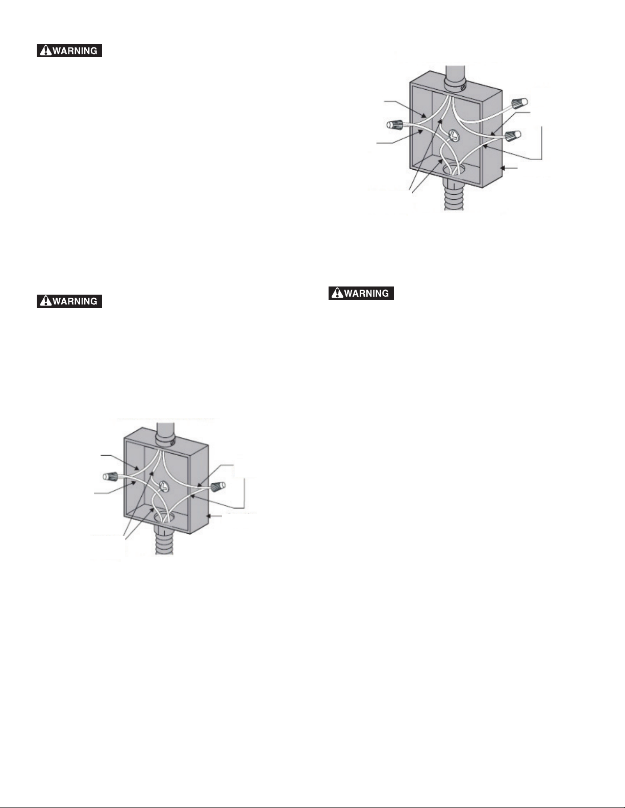
Connecting to a 3-wire power OR 4-wire power supply cable
electrical system
1. Disconnect the power supply.
2. In the circuit breaker, fuse box, or junction box, connect appliance
and power supply cable wires as shown below (3-wire, Figure 1;
4-wire, Figure 2).
3. Circuit breaker fuse rating must be above 40 A, and wire should
be 2/8 or 3/8 copper.
4. Minimum acceptable size of conductors should be no less than
10AWG, copper only, and no less than 167°F.
5. A wire-binding screw or stud used in the wire terminal should
be 10 or larger.
• The electrical power to the cooktop must be shut off while line
connections are being made. Failure to do so could result in
serious injury or death.
• An extension cord must not be used with this appliance. Such
use may result in a re, electrical shock or other personal injury.
Cable from Power Supply
Red Wire
Red Wire
Green Wire
(Grounding)
Cable from Appliance
White Wire
Black Wire
Junction Box
4-Wire Cable from Home Power Supply
Figure 2
The cooktop conduit wiring is approved for cop-
per wire connection only, if you have aluminum house wiring, use
only special connectors which are approved for joining copper and
aluminum wires conform with local codes and ordinances. Follow the
electrical connector manufacturer’s recommended procedure closely.
IMPORTANT - Save for the local electrical inspector's use.
Cable from Power Supply
Red Wire
Red Wire
Green Wire
(Grounding)
Cable from Appliance
3-Wire Cable from Home Power Supply
Figure 1
Black Wire
Junction Box
2
Page 3
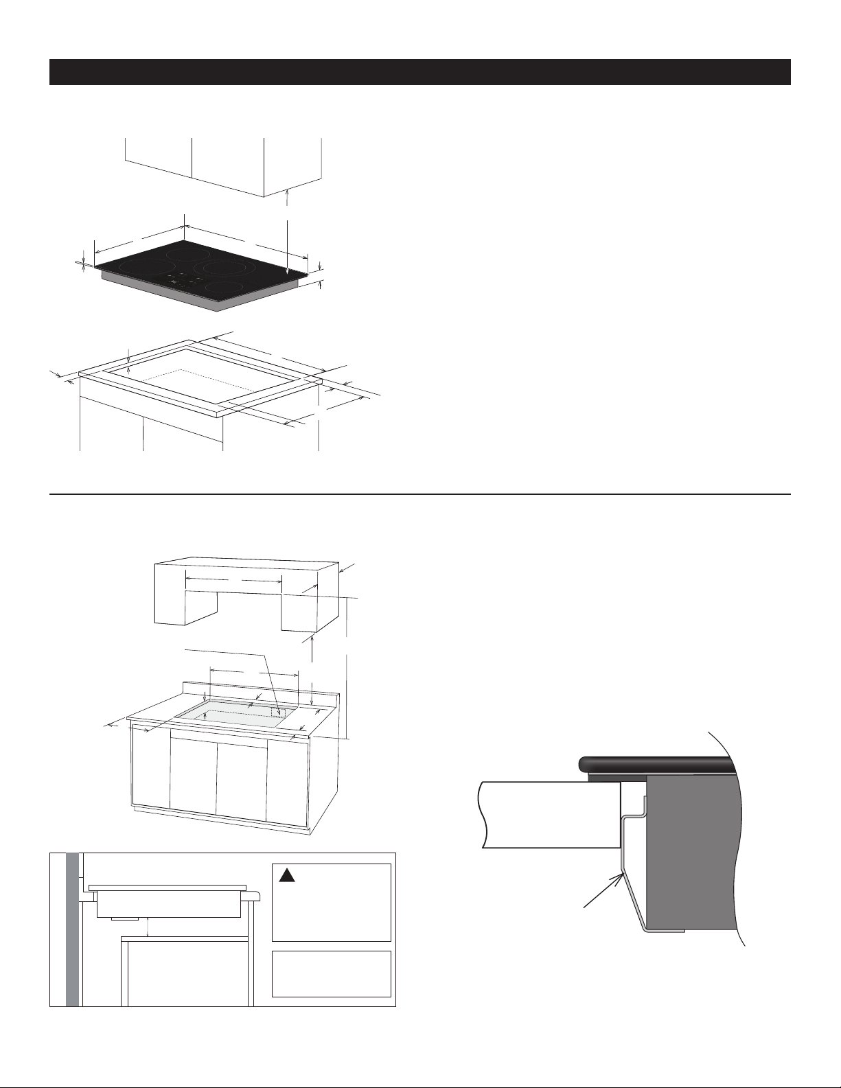
INSTALLATION – 30” MODEL SDH3042DB
B
Spacer Graphic Profile
COOKTOP AND CUTOUT DIMENSIONS (See Figure 3)
30” (76.2 cm) min. for cabinet
I*
* Do not obstruct these areas.
B
C
G
H
Figure 3
A
D
E
J
F
A. 30” (762 mm)
B. 21” (533 mm)
C. 5/32” (4 mm)
D. 2-5/32” (55 mm)
E. 29-5/8” (753 mm)
F. 19-7/8” (505 mm)
G. Minimum: 13/32” (10 mm)
Maximum: 25/32" (20mm)
H. Minimum: 2” (51 mm)
I. Minimum: 30” (762 mm)
J. Minimum: 2” (51 mm)
COOKTOP CUTOUT OPENING DIMENSIONS (See Figure 4)
A
Approximate location
of junction box,
min. 12" (304.8 mm)
below cooktop
H
Figure 4
G
2-1/2” (63.5 mm)
OVEN
E
I
CAUTION
!
It is very important to
keep 2-1/2” (63.5 mm)
distance between the
cooktop and the oven.
Note: do not put a
divider between the
oven and cooktop
C
D
F
A. 30” (762 mm)
B. 13” (330 mm)
C. 30” (762 mm) min to unprotected wood
D. 18” (457 mm)
E. 29-5/8” (753 mm)
F. 19-7/8” (505 mm)
G. 4-1/2 (114mm)
H. Minimum: 2” (51 mm)
I. Minimum: 2” (51 mm)
Countertop
Do not remove spacer
Figure 6
NOTE: The cooktops include spacers on both sides to ensure proper
airow once installed. Do not remove the spacers. See Figure 6 above.
Figure 5
3
Page 4

INSTALLATION – 36” MODEL SDH3652DB
B
COOKTOP AND CUTOUT DIMENSIONS (See Figure 7)
30” (76.2 cm) min. for cabinet
I*
B
A
C
G
H
E
* Do not obstruct these areas.
D
J
F
A. 36” (914 mm)
B. 21” (533 mm)
C. 5/32” (4 mm)
D. 2-5/32” (55 mm)
E. 35-3/8” (899 mm)
F. 19-7/8” (505 mm)
G. Minimum: 13/32” (10 mm) Maximum: 25/32"
(20mm)
H. Minimum: 2” (51 mm)
I. Minimum: 30” (762 mm)
J. Minimum: 2” (51 mm)
Figure 7
COOKTOP CUTOUT OPENING DIMENSIONS (See Figure 8)
A
Approximate location
of junction box,
min. 12" (304.8 mm)
below cooktop
H
E
G
I
C
D
F
A. 36” (914 mm)
B. 13” (330 mm)
C. 30” (762 mm) min to unprocted wood
D. 18” (457 mm)
E. 35-5/8” (899 mm)
F. 19-7/8” (505 mm)
G. 4-1/2" min (114 mm)
H. Minimum: 2" (51 mm)
I. Minimum: 2” (51 mm)
Figure 8
4
Page 5

AFTER INSTALLATION
1. Remove all the stickers and items from the top of the cooktop
surface.
2. Clean cooktop before use. Dry with a soft cloth. See “Cleaning
Your Cooktop” in the operation manual for reference.
3. Read “Using the Cooktop” in the operation manual.
4. Turn on the power to the cooktop.
5. Verify all functions operate properly.
NOTE: If the cooktop does not work, or you nd any problem
in your operation, please check that the circuit breaker has not
tripped, or a fuse has not blown. For more information, please
See Troubleshooting Guide in the operation manual. If you do
not solve the problem by yourself, please contact us for assistance
or service
FCC STATEMENT
This device complies with Part 18 of the FCC Rules. NOTE:
This equipment has been tested and found to comply with the
limits for a Consumer ISM equipment, pursuant to Part 18 of
the FCC Rules. These limits are designed to provide reasonable
protection against harmful interference in a residential
installation. This equipment generates, uses and can radiate radio
frequency energy and, if not installed and used in accordance
with the instructions, may cause harmful interference to radio
communications. However, there is no guarantee that interference
will not occur in a particular installation.
Please note that changes or modications of this product is not
expressly approved by the party responsible for compliance could
void the user's authority to operate the equipment.
If this equipment does cause harmful interference to radio or
television reception, which can be determined by turning the
equipment off and on, the user is encouraged to try to correct the
interference by one or more of the following measures:
• Reorient or relocate the receiving antenna.
• Increase the separation between the equipment and receiver.
• Connect the equipment into an outlet on a circuit different from
that to which the receiver is connected.
Consult the dealer or an experienced radio/TV technician for help.
5
Page 6

NOTES
Page 7

NOTES
Page 8

SHARP ELECTRONICS CORPORATION • 100 Paragon Drive • Montvale, New Jersey 07645 • USA
SHARP ELECTRONICS OF CANADA LTD • 335 Britannia Road East • Mississauga, Ontario • L4Z 1W9 • Canada
 Loading...