

Page 1

SDAT50W(A)_FRONT 02.11.7, 17:091
1-BIT DIGITAL HOME THEATER
MODEL
SD-AT50W
OPERATION MANUAL
Page 2
SD-AT50W
Introduction
Contents
General Information
- Introduction / Special notes / Contents -
Thank you for purchasing this SHARP product. To obtain the best performance from
this product, please read this manual carefully. It will guide you in operating your
SHARP product.
The SD-AT50W system includes an AV c ontrol unit, a subwoofer/amplifier unit,
!
two front speakers, two surround speakers and a centre speaker.
Special notes
WARNINGS
When the ON/STAND-BY button is set at STAND-BY position, mains voltage is
!
still present inside the unit. When the ON/STAND-BY button is set at STAND-BY
position, the unit may be brought into operation by the timer mode or remote control.
This unit contains no user serviceable parts. Never remove covers unless qualified
!
to do so. This unit contains dangerous volt ages, always remove mains plug from
the socket before any service operation and when not in use for a long period.
To prevent fire or shock hazard, do not expose this appliance to dripping or
!
splashing. No objects filled with liquids, such as vases, should be placed on t he
apparatus.
Manufactured under license from Digital Theater Systems, Inc. US Pat.
No.5,451,942, 5,956,674, 5,974,380, 5,978,762 and other world-wide patents issued and pending. "DTS" and "DTS Digital Surround" are registered trademarks of
Digital Theater Systems, Inc. Copyright 1996, 2000 Digital Theater Systems, Inc.
All Rights Reserved.
Manufactured under license from Dolby Laboratories. "Dolby", "Pro Logic" and the
double-D symbol are trademarks of Dolby Laboratories. Confidential unpublished
works. 1992-1999 Dolby Laboratories. All rights reserved.
Page
"
General Information
Accessories . . . . . . . . . . . . . . . . . . . . . . . . . . . . . . . . . . . . . . . . . . . . . . . . . . . . . . . 3
Precautions . . . . . . . . . . . . . . . . . . . . . . . . . . . . . . . . . . . . . . . . . . . . . . . . . . . . . . . 4
Controls and indicators . . . . . . . . . . . . . . . . . . . . . . . . . . . . . . . . . . . . . . . . . . 5 - 7
"
Preparation for Use
System connections . . . . . . . . . . . . . . . . . . . . . . . . . . . . . . . . . . . . . . . . . . . . . . 8, 9
Aerial connection . . . . . . . . . . . . . . . . . . . . . . . . . . . . . . . . . . . . . . . . . . . . . . . . . 10
Audio connectio n of other equipment . . . . . . . . . . . . . . . . . . . . . . . . . . . . . 10, 11
Connecting to the AC socket . . . . . . . . . . . . . . . . . . . . . . . . . . . . . . . . . . . . . . . . 12
Headphones . . . . . . . . . . . . . . . . . . . . . . . . . . . . . . . . . . . . . . . . . . . . . . . . . . . . . 12
System installation . . . . . . . . . . . . . . . . . . . . . . . . . . . . . . . . . . . . . . . . . . . . . 12, 13
Remote control . . . . . . . . . . . . . . . . . . . . . . . . . . . . . . . . . . . . . . . . . . . . . . . . . . . 14
General control . . . . . . . . . . . . . . . . . . . . . . . . . . . . . . . . . . . . . . . . . . . . . . . . . . . 14
Setting the clock . . . . . . . . . . . . . . . . . . . . . . . . . . . . . . . . . . . . . . . . . . . . . . . . . . 15
"
Basic Operation
Listening to the radio . . . . . . . . . . . . . . . . . . . . . . . . . . . . . . . . . . . . . . . . . . . . . . 16
Listening to the me morised station . . . . . . . . . . . . . . . . . . . . . . . . . . . . . . . . . . 17
Listening to the playback sound from the connected equipment . . . . . . . . . . 18
"
Advanced Features
Enjoying surround sound (sound mode) . . . . . . . . . . . . . . . . . . . . . . . . . . 19 - 21
Speaker settings . . . . . . . . . . . . . . . . . . . . . . . . . . . . . . . . . . . . . . . . . . . . . . . 22, 23
Timer and sleep operation . . . . . . . . . . . . . . . . . . . . . . . . . . . . . . . . . . . . . . 24 - 26
Changing the registration in the remote control . . . . . . . . . . . . . . . . . . . . . . . . 27
Operating the connected TV . . . . . . . . . . . . . . . . . . . . . . . . . . . . . . . . . . . . . . . . 28
"
References
Error indicator s a nd w ar nings . . . . . . . . . . . . . . . . . . . . . . . . . . . . . . . . . . . . . . . 28
Troubleshooting chart . . . . . . . . . . . . . . . . . . . . . . . . . . . . . . . . . . . . . . . . . . 29, 30
Maintenanc e . . . . . . . . . . . . . . . . . . . . . . . . . . . . . . . . . . . . . . . . . . . . . . . . . . . . . 30
Optional accessories . . . . . . . . . . . . . . . . . . . . . . . . . . . . . . . . . . . . . . . . . . . . . . 30
Specifications . . . . . . . . . . . . . . . . . . . . . . . . . . . . . . . . . . . . . . . . . . . . . . . . . . . . 31
2
SD-AT50W(A)1.fm02/11/8
Page 3
Accessories
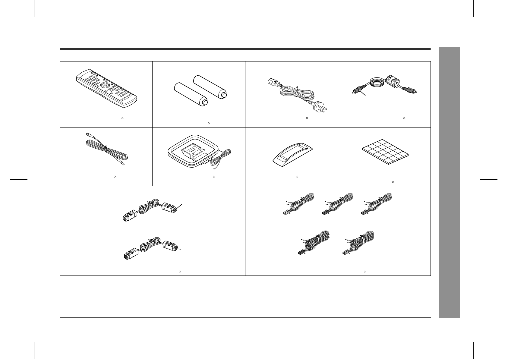
Please confirm that the following accessories are included.
SD-AT50W
Orange
Remote control 1 "AA" size battery (UM/SUM-3, R6, HP-7
FM aerial 1 AM loop aerial 1 Stand 1 Antislip speaker cushion sheet
(For signal/power)
(For sound)
System connection cable 2 Speaker connection lead 5
Note:
Only the above accessories are included.
or similar) 2
Blue
Black
AC power lead 1 Digital audio cable 1
(20 pcs.) 1
White
approx. 5 m
(15 feet)
Blue
approx. 15 m (45 feet) approx. 15 m (45 feet)
Green
approx. 5 m
(15 feet)
Red
approx. 5 m
(15 feet)
Grey
- Accessories -
General Information
3
SD-AT50W(A)1.fm02/11/8
Page 4
SD-AT50W
Precautions
- Precautions -
General Information
"
General
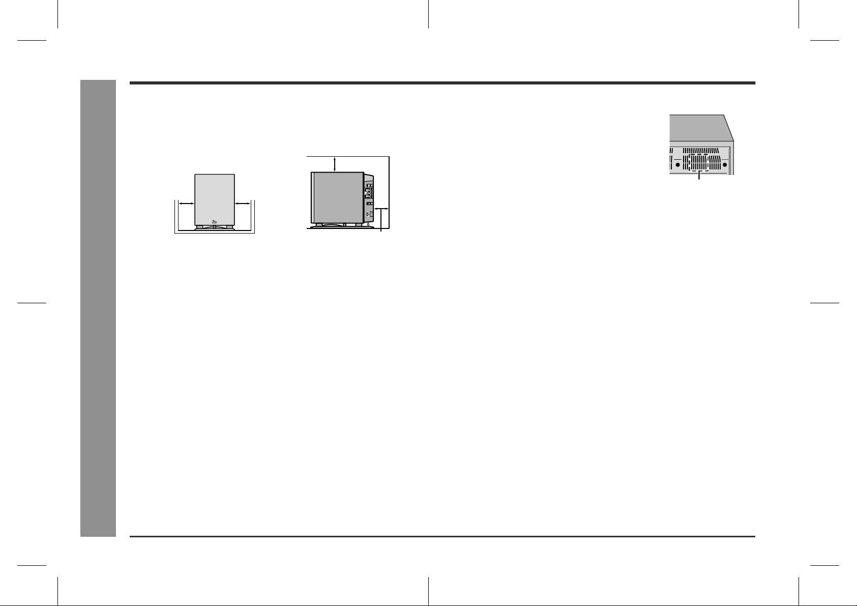
Please ensure that the subwoofer/amplifier unit is positioned in a well-ventilated
!
area and that there is at least 10 cm (4") of free spac e along the sides an d back.
There must also be a minimum of 15 cm (6") of free space on the top of the subwoofer/amplifier unit.
15 cm (6")
10 cm (4")
Use the system on a firm, level surface free from vibration.
!
Keep the system away from direct sunlight, strong magnetic fields, excessive dust,
!
humidity and electronic/electrical equipment (home computers, facsimiles, etc.)
which generate electrical noise.
Do not place anything on top of the components.
!
Do not expose the system to moisture, to temperatures higher than 60°C (140°F)
!
or to extremely low temperatures.
If the system does not work properly, unplug and plug it in again. Then turn on the
!
system.
In case of an electrical storm, unplug the subwoofer/amplifier unit for safety.
!
Hold the AC power plug by the he ad when removing it from the wall socket, as
!
pulling the lead can damage internal wires.
!
Do not remove the outer cover, as this may result in electric shock. Refer
internal service to your local SHARP service facility.
The ventilation should not be impeded by covering the ventilation openings with
!
items, such as newspapers, tablecloths, curtains, et c.
No naked flame sources, such as lighted candles, should be placed on the compo-
!
nents of the system.
Attention should be drawn to the environmental aspects of battery disposal.
!
This system should only be used within the range of 5°C - 35°C (41°F - 95°F).
!
10 cm (4")
10 cm (4")
Caution:
This subwoofer/amplifier unit is fitted with a cooling
!
fan at the rear for improved cooling. Do not cover the
opening in this section with any obstacles.
Cooling fan
The subwoofer/amplifier unit will get warm whil st being used. Do not touch warm
!
areas of the subwoofer/amplifier unit for prolonged periods to avoid damag e to
you.
This system is equipped with a special function which protects the amplifier circuit
!
from damage. When it is activated, the sound switch is turned off. In this case, set
the AV control unit to the stand-by mode and turn it on again.
"
Volume control
The sound level at a given volume set ting depends on speaker efficiency, loc ation
and various other factors. It i s advisable to avoid exposure to high volume levels,
which occur whilst turning the system on with the volume cont rol setting up high, or
whilst continually listening at high volumes.
Warning:
The voltage used must be the same as that specified by this system. Using this product with a higher voltage other than that specified is dangerous and may result in a
fire or other types of accident, causing damage. SHARP will not be held responsible
for any damage resulting from the use of this system with a voltage ot her than that
specified.
4
SD-AT50W(A)1.fm02/11/8
Page 5
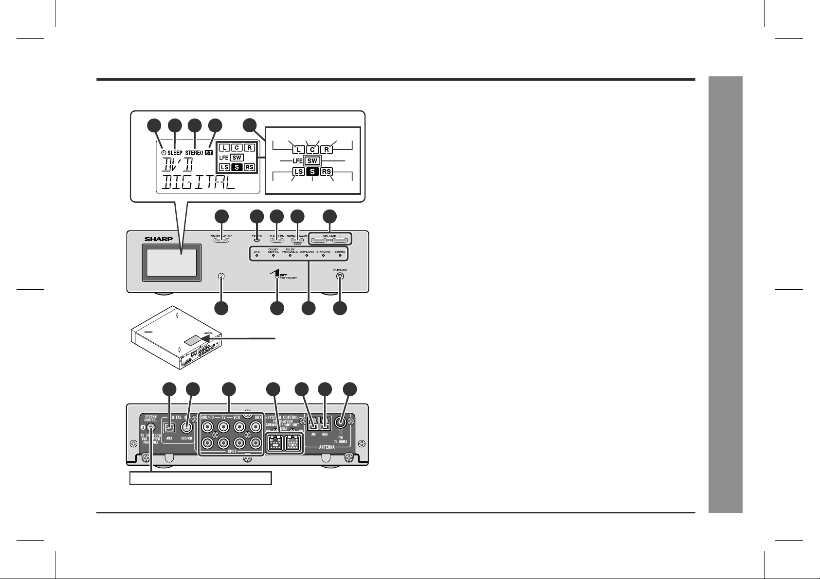
Controls and indicators
Display
1 2 3 4
Front
11 13 14
Back
15 16 17
5
(1)
(2) (3) (4) (5) (6)
(7)
10
)(11)(12)(13)
(9) (
6789
12
The rating label is located
on the bottom of the unit.
19
18
10
20 21
(8)
"
AV control unit
1.Timer Play Indicator
2.Sleep Indicator
3.FM stereo mode indicator
4.FM Stereo Receiving Indicator
5.Audio Signal Indic ators /Spea ker Indicators
(1) Left Front Speaker Indicator (8) Subwoofer Indicator
(2) Front Left Signal Indicator (9) Left Surround Speaker Indicator
(3) C entre Speaker Indicator (10)Surround Left Signal Indicator
(4) C entre Signal Indicator (11)Surround Monaural Signal
(5) Front Right Signal Indicator (12)Surround Right Signal Indicator
(6) Right Front Speaker Indicator (13)Right Surround Speaker Indicator
(7) Low Frequency Effect Indicator
6.On/Stand-by Button . . . . . . . . . . . . . . . . . . . . . . . . . . . . . . . . . . 14, 30
7.Timer Set Indicator . . . . . . . . . . . . . . . . . . . . . . . . . . . . . . . . . . . . . .24
8.Function Button . . . . . . . . . . . . . . . . . . . . . . . . . . . . . . . . . . . . . 16, 18
9.Digital/Analog Input Select or Tuner Band Select Button . . . . 16, 18
10.Volume Up and Down Buttons . . . . . . . . . . . . . . . . . . . . . . . . . . . . . 14
11.Remote Sensor . . . . . . . . . . . . . . . . . . . . . . . . . . . . . . . . . . . . . . . . . 14
12.Power Indicator . . . . . . . . . . . . . . . . . . . . . . . . . . . . . . . . . . . . . . . . . 14
13.Sound Mode Indicators . . . . . . . . . . . . . . . . . . . . . . . . . . . . . . .20, 21
14.Headphone Socket . . . . . . . . . . . . . . . . . . . . . . . . . . . . . . . . . . . . . . 12
15.Audio Digital Input Socket . . . . . . . . . . . . . . . . . . . . . . . . . . . . . . . .11
16.Coaxial Digital Audio Input Socket . . . . . . . . . . . . . . . . . . . . . . . . .10
17.Audio Input Sockets . . . . . . . . . . . . . . . . . . . . . . . . . . . . . . . . . .10, 11
18.System Connection Sockets (to subwoofer/amplifier unit) . . . . . .8
19.AM Loop Aerial Terminal . . . . . . . . . . . . . . . . . . . . . . . . . . . . . . . . . 10
20.Aerial Earth Terminal . . . . . . . . . . . . . . . . . . . . . . . . . . . . . . . . . . . . 10
21.FM 75 Ohms Aerial Socket . . . . . . . . . . . . . . . . . . . . . . . . . . . . . . . . 10
Indicator
Reference page
SD-AT50W
- Controls and indicators -
General Information
This product does not use this terminal.
5
SD-AT50W(A)1.fm02/11/8
Page 6
SD-AT50W
General Information
Controls and indicators (continued)
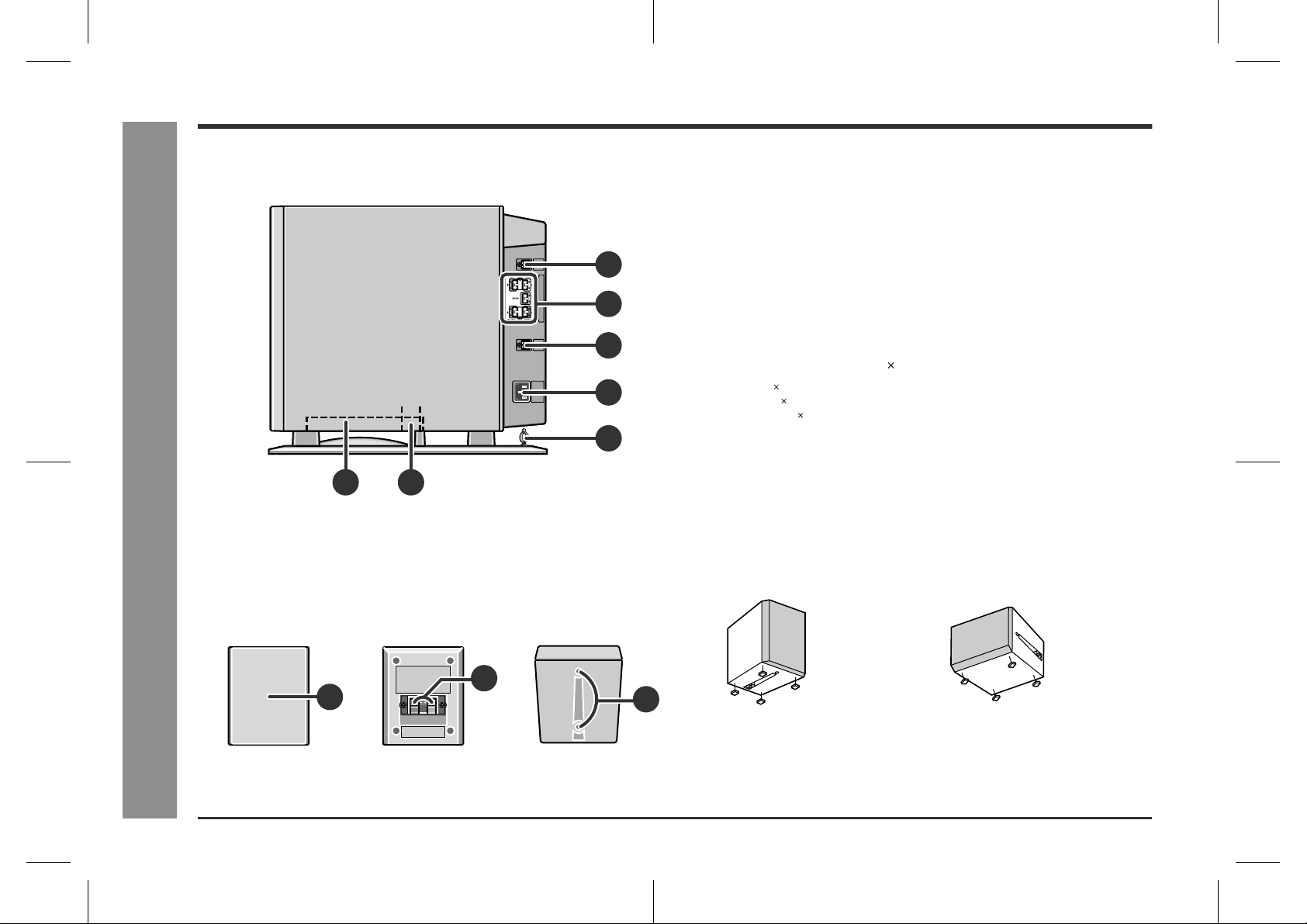
Side
21
- Controls and indicators -
!
Subwoofer/amplifier unit
1.Subwoofer
2.Bass Reflex Duct
3.System Connection Socket (to AV control unit) . . . . . . . . . . . . . . . .8
4.Speaker Terminals . . . . . . . . . . . . . . . . . . . . . . . . . . . . . . . . . . . . . . . .9
3
4
5
6
5.System Connection Socket (to AV control unit) . . . . . . . . . . . . . . . .8
6.AC Power Input Socket . . . . . . . . . . . . . . . . . . . . . . . . . . . . . . . . . . .12
7.Lead Holder . . . . . . . . . . . . . . . . . . . . . . . . . . . . . . . . . . . . . . . . . . . . .9
!
Satellite speaker 5
Front speaker 2: magnetically shielded
Centre speaker 1: magnetically shielded
Surround speaker 2: magnetically shielded
7
1.Speaker
2.Speaker Terminals . . . . . . . . . . . . . . . . . . . . . . . . . . . . . . . . . . . . . . . .9
3.Mounting Holes for Stand or Bracket (Optionally available) . . . . .13
Using anti slip speaker cushions:
You can install satellite speakers either vertically or horizontally.
Affix the cushions (supplied) to the bottom of the speakers to preven t the m from sli d ing or falling due to vibration.
(Vertical position) (Horizontal position)
Reference page
Reference page
Front Back Bottom
2
1
6
3
A sheet of speaker cushions (20 pcs.) i s supplied with this produ ct. Use 4 cushions
per speaker.
SD-AT50W(A)1.fm02/11/8
Page 7

!
Remote control
Reference page
2
3
4
5
6
7
8
9
10
1
1.Remote Control Transmitter . . . . . . . . . . . . . . . . . . . . . . . . . . . . . . 14
2.Direct Number Buttons . . . . . . . . . . . . . . . . . . . . . . . . . . . . . . . . 17, 27
3.Tuning Up Button . . . . . . . . . . . . . . . . . . . . . . . . . . . . . . . . . . . . . . . 16
13
14
15
16
17
18
19
20
21
4.Tuning Down Button . . . . . . . . . . . . . . . . . . . . . . . . . . . . . . . . . . . . . 16
5.Tuner Preset Down Button . . . . . . . . . . . . . . . . . . . . . . . . . . . . . . . . 17
6.Cursor Button . . . . . . . . . . . . . . . . . . . . . . . . . . . . . . . . . . . . . . .15, 24
7.Function Buttons . . . . . . . . . . . . . . . . . . . . . . . . . . . . . . . . . . . . . . 16, 18
8.Digital/Analog Input Select or Tuner Band Select Button . . . . . . . 16, 18
9.Sound Mode Select Buttons . . . . . . . . . . . . . . . . . . . . . . . . . . . . . . 21
10.TV On/Stand-by Button . . . . . . . . . . . . . . . . . . . . . . . . . . . . . . . .27, 28
11.TV Input Select Button . . . . . . . . . . . . . . . . . . . . . . . . . . . . . . . . . . . 28
12.TV Channel Select Buttons . . . . . . . . . . . . . . . . . . . . . . . . . . . . . . . 28
13.On/Stand-by Button . . . . . . . . . . . . . . . . . . . . . . . . . . . . . . . . . . . . . . .14
14.Display Brightness Select or Clock Display Button . . . . . . . .14, 15
15.Timer Button . . . . . . . . . . . . . . . . . . . . . . . . . . . . . . . . . . . . . . . . . . . 24
16.Clear Button . . . . . . . . . . . . . . . . . . . . . . . . . . . . . . . . . . . . . . . . . . . . 17
17.Amplifier Initial Setting Button . . . . . . . . . . . . . . . . . . . . . . . . . . . . 22
18.Tuner Preset Up Button . . . . . . . . . . . . . . . . . . . . . . . . . . . . . . . . . . 17
19.Enter Button . . . . . . . . . . . . . . . . . . . . . . . . . . . . . . . . . . 15, 17, 22, 24
20.Return Button . . . . . . . . . . . . . . . . . . . . . . . . . . . . . . . . . . . . . . . . . . 23
21.Dynamic Sound Select Button . . . . . . . . . . . . . . . . . . . . . . . . . . . . . 21
22.TV Volume Up and Down Buttons . . . . . . . . . . . . . . . . . . . . . . . . . . 28
23.Volume Up and Down Buttons . . . . . . . . . . . . . . . . . . . . . . . . . . . . . . 14
Buttons with " " mark in the illustration can be operated on the remote control only.
22
SD-AT50W
- Controls and indicators -
General Information
11
12
23
7
SD-AT50W(A)1.fm02/11/8
Page 8
SD-AT50W
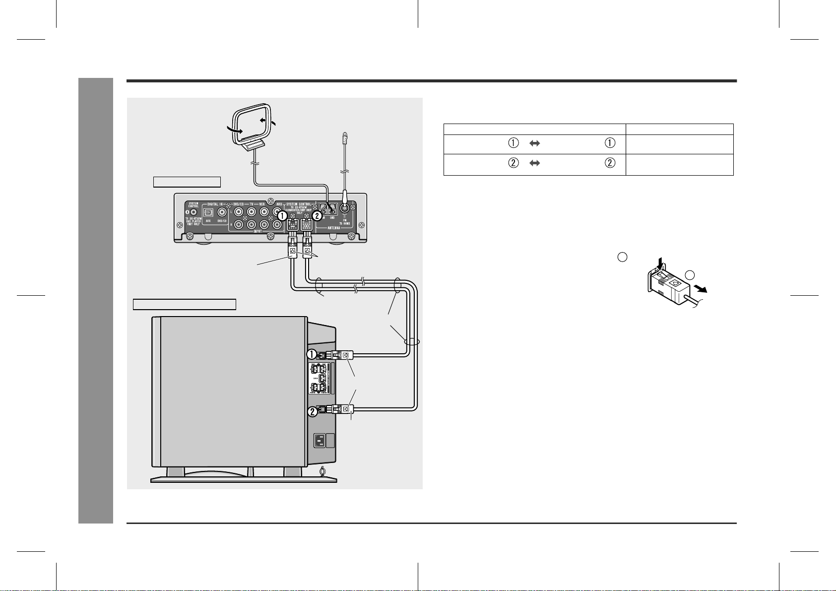
System connections
FM aerial
AM loop aerial
AV control unit
!
Connecting the components
Connect the AV control unit and subwoofer/amplifier unit as follows.
AV control unit
AV control unit
Connecting components
Subwoofer/
amplifier unit
Subwoofer/
amplifier unit
System connection cable
(For sound, black)
System connection cable
(For signal/power, blue)
Lead
Caution:
Make sure to connect the system after unplugging the subwoofer/amplifier unit.
"
Put the 2 system connection cables (f or sound and signal/ power) together. If not,
"
noises may be heard.
To unplug the system connection cable:
1
Push
2
Unplug
Subwoofer/amplifier unit
System
connection cable
(For sound, black)
Arrow upward
Closer
Closer
- System connections -
Preparation for Use
Arrow to the left
System
connection cable
(For signal/power,
blue)
8
SD-AT50W(A)1.fm02/11/8
Page 9
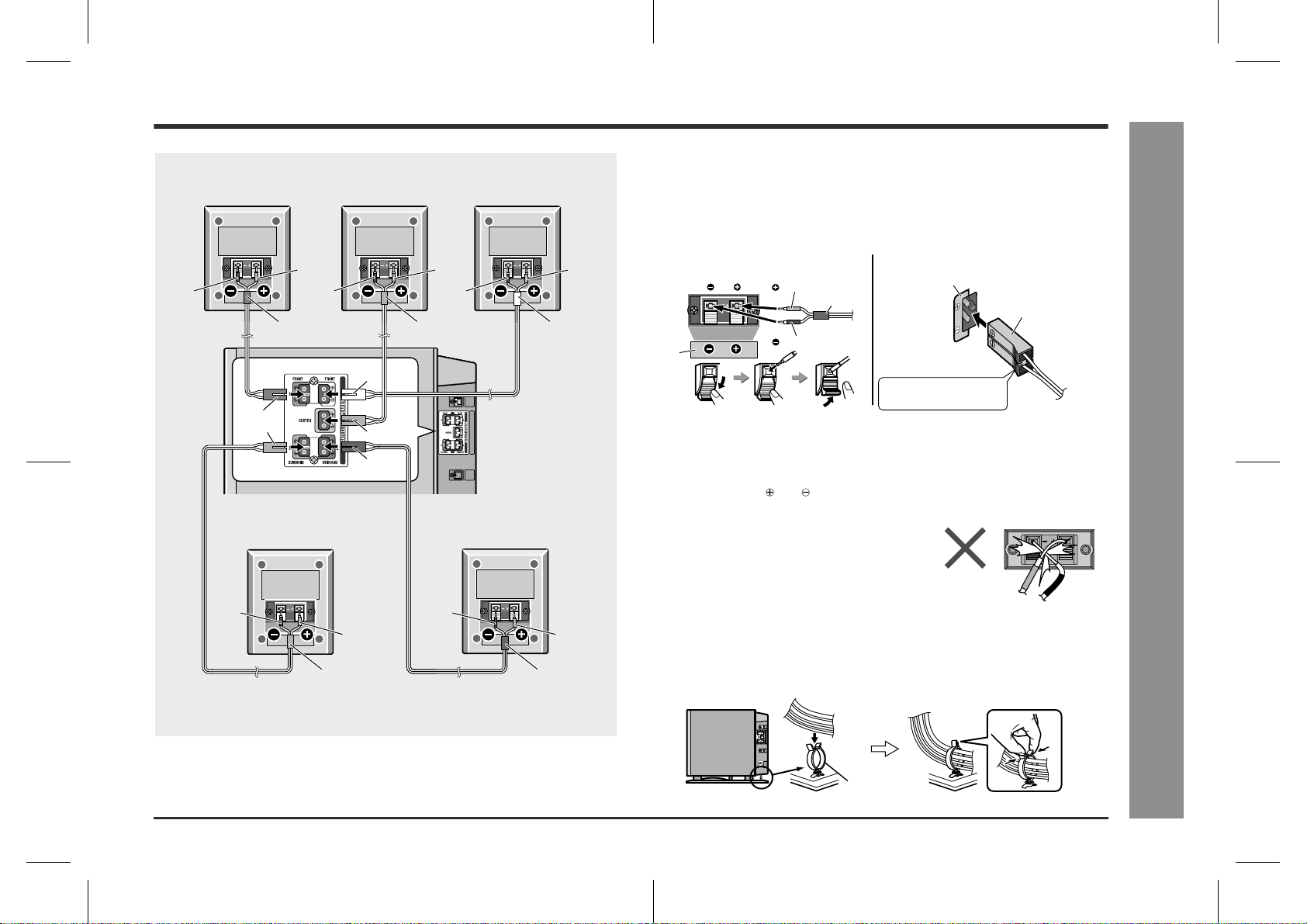
!
Connecting the satellite speakers
Front speaker
(Right)
Centre speaker
Front speaker
(Left)
The speaker terminals on the subwoofer/amplifier unit, the tube and plugs of the
speaker lead, and speaker labels are distinguished by colours.
Connect the speaker and the unit by matching the colours.
Connect the speaker leads to the satellite speakers first and then to the subwoofer/amplifier unit.
SD-AT50W
Red Red Red
Black BlackBlack
Red
White
Red
Grey
Black Black
Red Red
Grey
Surround speaker
(Right)
Green
Green
Blue
White
Subwoofer/
amplifier unit
Blue
Surround speaker
(Left)
(Satellite speaker)
Speaker terminals
Label
Red
Black
Tube
(Subwoofer/amplifier unit)
Label
Speaker plug
Plug in with the rising
side facing to the left.
Caution:
Make sure to connect the speakers after unplugging the subwoofer/amplifier unit.
"
Insert the speaker plug fully with the rising side facing to the left.
"
Hold the speaker plug when removing it from the subwoofer/amplifier unit. Pulling
"
the lead may cause malfunction to the subwoofer/amplifier unit.
Do not mistake the and , and right and left terminals of the speaker leads. (The
"
right speaker is placed on the right when you face the system. See page 13.)
"
Never short-circuit the speaker leads. If the
speaker leads are short-circuited, the protection circuit is activated and the system enters
the stand-by mode. In such a case, check that
the leads are properly connected before turning the power on again.
"
Only the supplied speakers should be used with this product.
Do not stand or sit on the speakers. You may be injured.
"
Binding leads:
Tie the leads connected to the subwoofer/amplifier unit with a lead holder.
- System connections -
Preparation for Use
Lead holder
SD-AT50W(A)1.fm02/11/8
9
Page 10
SD-AT50W
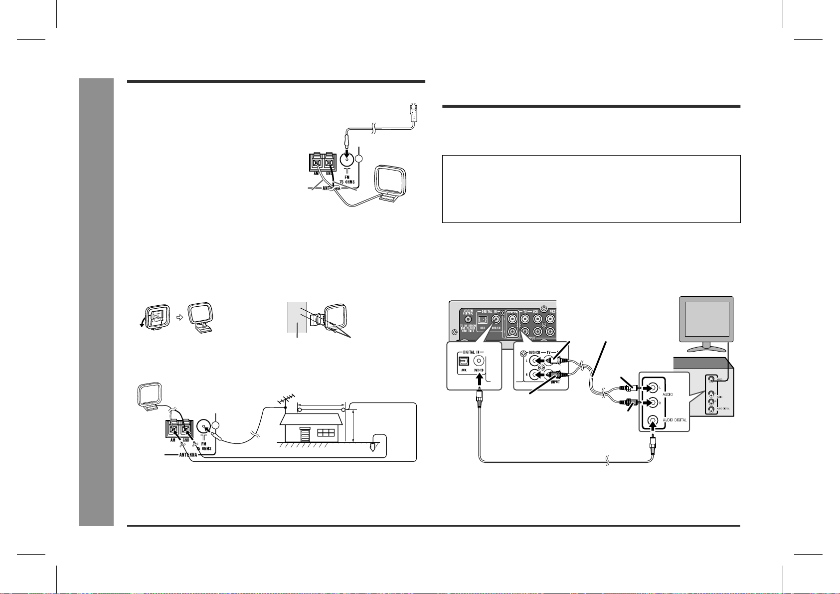
Aerial connection
Audio connection of other
Preparation for Use
Supplied FM aerial:
Connect the FM aerial wire to the FM 75 OHMS
socket and position the FM aerial wire in the direction where the strongest signal can be received.
Supplied AM loop aerial:
Connect the AM loop aerial wire to the AM and
GND terminals. Position the AM loop aerial for
optimum reception. Place the AM loop aerial on
a shelf, etc., or attach it to a stand or a wall with
screws (not supplied).
White
Black
Notes:
Placing the aerial on the syst em or near the AC power lead may cause noise
"
pickup. Place the aerial away from the system for better reception.
When static is still heard even after adjusting the position of the AM loop aerial, try
"
reversing the wire connections.
Installing the AM loop aerial:
< Assembling > < Attaching to the wall >
Wall Screws (not supplied)
External FM or AM aerial:
Use an external FM or AM aerial if you require better reception. Consult your dealer.
AM loop aerial
External
FM aerial
15 m (49 feet )
- Aerial connection / Audio connection of other equipment -
Earth wire
External
AM aerial
7.5 m (25 feet )
Earth rod
Note:
When using an external AM aerial, be sure to keep the wire of the AM loop aerial
connected.
equipment
You can hear the sound of other equipment via this product. Connect the DVD
player, VCR or digital tuner to TV directly to receive the images (refer to the operation
manual of each equipment).
Caution:
Turn off all other equipment before making this connection.
Notes:
Refer to the operation manual of the equipment to be connected.
"
Insert the plugs fully to avoid fuzzy pictures or noise.
"
!
Connection for the DVD or CD player
sound
You can hear the sound by connecting either the audio cable or digital audio cable.
(The audio cable is not supplied. Purchase a commercially available cable.)
TV
Audio cable
White
(commercially available)
To audio
output sockets
White
To audio
Red
input sockets
To coaxial digital
audio input socket
Digital audio cable
(supplied)
Note:
When the digital audio output socket of the DVD or CD player is optical, connect to
the AUX terminal of this unit regardless of connection type. (Refer to "Connection for
the digital tuner sound" on page 11.)
Red
DVD player
(CD player)
To coaxial digital
audio output socket
10
SD-AT50W(A)1.fm02/11/8
Page 11

SD-AT50W
!
Connection for the TV sound
Using the audio cable, you can listen to TV sound with this system.
(The audio cable is not supplied. Purchase a commercially available cable.)
White
Red
TV
!
Connection for the VCR sound
Using the audio cable, you can listen to VCR sound with this system.
(The audio cable is not supplied. Purchase a commercially available cable.)
TV
VCR
To audio
input sockets
Red
To audio
output sockets
White
Red
Audio cable
(commercially available)
White
To audio
input sockets
Audio cable
(commercially available)
White
To audio
output sockets
Red
!
Connection for the digital tuner sound (or
other optical digital equipment such as an
MD player)
You can hear the sound by connecting either the audio cable or optical digital cable.
(Audio cable and optical digital cable are not included. Please purchase either our
optional cables or commercially available ones.)
If you are using the digital tuner with the optical output socket , you can enjoy better
sound by connecting the tuner to the optical digital input socket of the AV control unit.
Audio cable
(commercially available)
To audio
White
White
Red
To audio
input sockets
To optical digital
audio input socket
Optical digital cable
(option: AD-M3DC)
Note:
When connecting with an optical digital cable, set the digital output of the digital tuner
to PCM. Refer to the operation manual of the digital tuner.
output sockets
Red
Digital tuner, etc.
To optical digital audio
output socket
Digital equipment such as
an MD player
TV
Preparation for Use
- Audio connection of other equipment -
11
SD-AT50W(A)2.fm02/11/8
Page 12

SD-AT50W
Connecting to the AC socket
System installation
Preparation for Use
!
Connecting the AC power lead
Subwoofer/amplifier unit :
After checking all the connections, connect the AC power lead to the AC power input
socket, then to the wall socket.
(AC INPUT)
Notes:
The power is supplied to the AV control unit by the subwoofer/amplifier unit. The
"
AV control unit is not equipped with a power lead.
Never use a power lead other than the one supplied. Otherwise, a malf unction or
"
an accident may occur.
Unplug the subwoofer/amplifier unit if it will not be used for prolonged periods of
"
time.
Headphones
Before plugging in or unplugging the headphones, reduce the volume.
"
Be sure your headphones have a 3.5 mm (1/8") diameter plug and are between 16
"
ohms and 50 ohms impedance. The recommended impedance is 32 ohms.
Plugging in the headphones disconnects the speakers automatically. Adjust the
"
volume using the VOLUME buttons.
You cannot use the surround feature with headphones.
"
!
Installing the AV control unit
The AV control unit can be installed either vertically or horizontally.
Use the supplied stand for vertical installation.
12
- Connecting to the AC socket / Headphones / System installation -
SD-AT50W(A)2.fm02/11/8
Page 13

SD-AT50W
!
Placing the speaker system
The best surround effect will be achieved by placing each speaker at the same distance from the listening position.
It is recommended to arrange the speakers as shown below.
Identify each speaker by the tube colour.
Centre
Subwoofer/
amplifier unit
Surround
speaker (left)
(blue)
Same distance
Front
speaker (left)
(white)
Centre speaker (green)
speaker
(green)
Front
speaker (right)
(red)
Surround
speaker (right)
(grey)
Same distance
The speaker stands and speaker wall bracket s are optionally available (see page
30). Refer to their instructions for assembly.
The speakers may be placed beside or near the TV as they are magnetically
shielded. However, colour variation may occur, depending on the type of the TV.
If colour variation occurs...
Turn off the TV (from the power switch).
After 15 - 30 minutes, turn the TV on again.
If the colour variation is still present...
Move the speakers further away from the TV.
Refer to the user's manual of the TV for details.
Caution:
When carrying the subwoofer/amplifier unit, be careful not to touch the subwoofer
located near bottom. Be sure to hold it by the bottom to avoid subwoofer breakage.
- System installation -
Preparation for Use
Front speaker (left) (white)
Front speaker (right) (red)
Notes:
Place the TV halfway between the front speakers.
"
It is recommended that the centre speaker be placed near the television.
"
Place the surround speakers at a position just above the height of your ears.
"
Set the subwoofer/amplifier unit on a stable, sturdy floor.
"
If speakers cannot be placed at equal distances, refer to "Speaker delay setting"
"
(see page 22).
The speaker grille is not removable.
"
Subwoofer
Correct
13
SD-AT50W(A)2.fm02/11/8
Page 14

SD-AT50W
Remote control
General control
Preparation for Use
!
Battery installation
1 Open the battery cover.
2 Insert the batteries according to the direction indicated in the bat-
tery compartment.
When inserting or removing the batt eries, push them towards t he battery terminals.
3 Close the battery cover.
Precautions for battery use:
Replace all old batteries with new ones at the same time.
"
Do not mix old and new batteries.
"
Remove the batteries if the system will not be used for long periods of time. This
"
will prevent potential damage due to battery leakage.
Caution:
Do not use rechargeable batteries (nickel-cadmium battery, etc.).
"
Installing the batteries incorrectly may cause the system to malfunction.
"
Notes concerning use:
Replace the batteries if the operating distance is reduced or if the operation
"
becomes erratic. Purchase 2 "AA" size batteries (UM/SUM-3, R6, HP-7 or similar).
Periodically clean the transmitter on the remote control and the sensor on the AV
"
control unit with a soft cloth.
Exposing the sensor on the AV control unit to strong light may interfere with oper-
"
ation. Change the lighting or the direction of the AV control unit.
Keep the remote control away from moisture, heat, shock, and vibrations.
"
!
- Remote control / General control -
Test of the remote control
Check the remote control after checking all the connections (see pages 8 - 10 and 12).
Point the remote control directly at the remote sensor on the AV control unit.
The remote control can be used within the range shown below:
Press the ON/STAND-BY button. Does the power turn on? Now, you can enjoy your system.
!
To turn the power on
Press the ON/STAND-BY button.
The power indicator lights up.
If the power does not turn on, check if the power leads are plugged in properly.
!
Volume control
Press the VOLUME + button to increase the volume and the VOLUME - button for
decreasing.
012 39 40
!
To change the display brightness (2 levels)
You can change the brightness of the AV control unit display by holding down the
DISPLAY button on the remote control for 2 seconds or more.
Dimmed Brightened
.....
14
Remote sensor
AV control unit
0.2 m - 6 m
(8" - 20')
Power indicator
SD-AT50W(A)2.fm02/11/8
Page 15

Setting the clock
SD-AT50W
By setting the correct time on t he AV control unit, you can use it not only as a clock
but also for timer playback.
In this example, the clock is set for 9:30.
Press the DISPLAY button.
1
Within 5 seconds, press the ENTER button.
2
Press the or button to adjust the
3
hour and then press the ENTER button.
Press the or button once to advance the time by 1 hour. Hold it down to advance continuously.
Press the or button to adjust the
4
minutes and then press the ENTER
button.
Press the or button once to advance the time by 1 minute. Hold it down
"
to advance continuously.
The hour will not advance even if minutes advance from "59" to "00".
"
The clock starts from "0" second. (Seconds are not displayed.)
"
The display returns to normal after approx. 2 seconds.
"
To confirm the time display:
Press the DISPLAY button.
The time display will appear for about 5 seconds.
To readjust the clock:
Perform "Setting the clock" from the beginning.
In step 1, the time will be displayed. If the clock is cleared, "ADJUST" appears.
"
Follow steps 2 - 4.
"
Note:
You can set the clock even when the system is in the stand-by mode.
Caution:
Unplugging the subwoofer/amplifier unit or a power failure will clear the clock setting.
Perform "Setting the clock" from the beginning.
- Setting the clock -
Preparation for Use
15
SD-AT50W(A)2.fm02/11/8
Page 16

SD-AT50W
Basic Operation
Listening to the radio
- Listening to the radio -
Press the ON/STAND-BY button to turn the power on.
1
To enter tuner function, display "FM" or "AM" by pressing the
2
TUNER button.
Press the BAND button repeatedly to select the desired f reque ncy
3
band (FM or AM).
Press the TUNING ( or ) button to tune i n to the desired sta tion.
4
Manual tuning:
Press the TUNING button as many times as required to tune in to the desired
station.
Auto tuning:
When the TUNING button is pressed for more than 0.5 seconds, scanning will
start automatically and the tuner will stop at the first receivable broadcast station.
Notes:
When radio interference occurs, auto scan tuning may stop automatically at
!
that point.
Auto scan tuning will skip weak signal stations.
!
To stop the auto tuning, press the TUNING button again.
!
To receive an FM stereo transmission:
Press the BAND button to display the "STEREO" indicator.
"ST" will appear when an FM broadcast is in stereo.
!
FM stereo receiving indicator
16
FM stereo mode indicator
If the FM reception is weak, press the BAND button to extinguish the "STEREO"
!
indicator. The reception changes to monaural, and the sound becomes clearer.
After use:
Press the ON/STAND-BY button to enter the power stand-by mode.
Note:
This product can receive FM stereo/FM monaural and AM monaural broadcasts. AM
stereo broadcasts will not be played in stereo.
SD-AT50W(A)2.fm02/11/8
Page 17

Listening to the memorised station
SD-AT50W
"
Memorising a station
You can store 40 AM and FM stations in memory and recall them at the push of a
button. (Preset tuning)
Perform steps 1 - 3 in "Listening to the radio" on page 16.
1
Press the ENTER button to enter the preset tuning saving mode.
2
Within 5 seconds, press the TUNER
3
PRESET ( or ) button to select
the preset channel number.
Store the stations in memory, in order, starting with preset channel 1.
Within 5 seconds, press the ENTER
4
button to store that station in memory.
Repeat steps 1 - 4 to set other stations, or to change a preset sta-
5
tion.
When a new station is stored in memory, the station previously memorised will
be erased.
Note:
The backup function protects the memorised stations for a few hours should there be
a power failure or the AC power lead disconnection.
"
To recall a memorised station
Press the TUNER PRESET ( or ) button to select the desired station.
Preset channel Frequency and frequency band
To select a preset station with the direct number buttons:
Stations 1 - 10: Press the corresponding number ("1" - "10/0").
Stations 11 - 40: Press the ">10" button and then the memorised preset number.
For example, to choose 28
1 Press the ">10" button.
2 Press the "2" button.
3 Press the "8" button.
Press buttons within 5 seconds.
"
To erase all the contents of the preset
memory
1 Hold the CLEAR button down for 3 seconds
or more.
2 Whilst "CLEAR" is display ed, press the EN-
TER button.
Basic Operation
- Listening to the memorised station -
17
SD-AT50W(A)2.fm02/11/8
Page 18

SD-AT50W
Basic Operation
Listening to the playback sound from the connected equipment
Example) Listening to a DVD or CD player
Press the ON/STAND-BY button on the AV control unit or the re-
1
mote control to turn the power on.
Turn on the DVD or CD player.
2
Press the FUNCTION button to set the
3
function to "DVD".
The DVD button on the remote control can also set the function to DVD.
!
Press the DIGITAL/ANALOG button to switch the sound to "AUX ANALOG"
!
or "AUX DIGITAL" depending on the connected input terminal.
When connecting the DVD or CD player to the AUX socket of this unit, select
!
"AUX".
Press the playback button of the DVD or CD player.
4
Caution:
The system gets warm when used for a long time. It does not mean the system is
damaged.
Note:
A safety feature automatically sets the syst em t o the power stand-by mode if you set
the volume level too high. If this happens, lower the volume level.
18
- Listening to the playback sound from the connected equipment -
SD-AT50W(A)2.fm02/11/8
Page 19

Enjoying surround sound (sound mode)
You can enjoy the surround sound recorded in Dolby Digital or DTS if this system is
digitally connected to a DVD player.
You can also enjoy 2-channel stereo sound in Dolby Pro Logic II.
SD-AT50W
DVD player
Digital tuner, etc.
Dolby Digital signal
DTS signal
Stereo signal
Dolby Digital
DTS
Dolby Pro Logic II
Types of surround Types of input signal Contents Switchable sound
mode
Dolby Digital
DTS (Digital Theater Systems)
Dolby Pro Logic II
One of the digital audio systems for theatrical use. You can
enjoy the stereophonic effect in the home theatre system.
Digital input from discs with this trademark The disc recorded in Dolby Digital is recognised by the sys-
tem automatically when it is played back.
One of the digital audio systems for theatrical use. As the
sound quality is emphasised, you can enjoy the realistic
sound effect in the home theatre system. The disc recorded
in DTS is recognised by the system automatically when it is
played back.
Digital input from discs with this trademark Standard
Inputs from stereo-recorded discs, videotapes, etc. When playing a stereo-recorded disc or videotape, it is recog-
nised by the Dolby Pro Logic II function and the sound is
changed to the 5.1ch digital surround sound automatically.
More natural sound effect can be achieved.
If (*) is selected, the " " indicator goes out.
(To select the sound mode, see page 21.)
Stereo
Standard
(Dynamic sound)
Stereo
(Dynamic sound)
Stereo (*)
Surround (*)
Standard
(Dynamic sound)
Advanced Features
- Enjoying surround sound (sound mode) -
Caution:
The surround sound recorded in Dolby Digital or DTS cannot be enjoyed if this system is connected to a DVD player in analogue. The DTS recorded sound especially, cannot
be emitted in analogue. Refer to the operation manual of the DVD player for details.
SD-AT50W(A)2.fm02/11/8
19
Page 20

SD-AT50W
Advanced Features
Enjoying surround sound (sound mode) (continued)
Acoustic effect
Standard
The maximum of 5.1ch surround sound
is reproduced to provide three-dimensional effect. The system automatically
emits the 5.1ch sound according to the
recorded audio signal.
The STANDARD indicator lights up.
Dynamic sound
You can enjoy the normal surround with various scenes.
MOVIE: The bass level is increased for powerful sound effect.
MUSIC: You can enjoy lively sound by producing the articulate sound.
NIGHT: Soft but powerful sound is achieved even at low volumes.
Surround
This mode provides an expansive listening area by emitting 2-channel
sound.
The SURROUND indicator lights
up.
Stereo
You can enjoy the great acoustic effects of the front speakers and sub-
- Enjoying surround sound (sound mode) -
woofer.
The STEREO indicator lights up.
DOLBY DIGITAL/DTS indicator:
The input signal is recognised automatically and the indicator lights up.
DOLBY PRO LOGIC II indicator:
This indicator is lit when the 2ch signals are ent ered to extend them to the 5. 1ch
!
surround sound.
Even the 2ch sound recorded with Dolby Digital will be extended to the 5.1ch.
!
Notes:
When the surround mode is set to the standard or surround mode, the sound of
!
monaural signals is heard only from the centre speaker.
When the surround mode is set to stereo, the same monaural sound is reproduced
!
in both the right and left channels.
The surround indicator is lit according to the input audio source.
!
1 Front Left Signal Indicator
2 Centre Signal Indicator
3 Front Right Signal Indicator
4 LFE (Low Frequency Effect) Signal Indicator
5 Surround Left Signal Indicator
6 Surround Monaural Signal Indicat o r
7 Surround Right Signal Indicat o r
1 3
4
2
20
6
57
SD-AT50W(A)2.fm02/11/8
Page 21

!
Changing the sound mode
SD-AT50W
To enjoy in the standard mode:
Whilst the disc is playing, press the STANDARD button.
"STANDARD" will appear.
To enjoy with dynamic sound in the standard mode:
Whilst the disc is playing, press the DYNAMIC SOUND button.
Each press of this button changes the mode in the order of "MOVIE" "MUSIC"
"NIGHT".
Press the STANDARD button to restore the normal surround sound.
To enjoy in the surround or stereo mode:
Whilst the disc is playing, press the STEREO/SURROUND button.
"SURROUND" or "STEREO" will appear.
Each time you press the button, the display switches
between "SURROUND" and "STEREO".
Notes:
The sound mode is changed to "STANDARD" by pressi ng the DYNAMIC SOUND
"
button whilst in the stereo or surround mode.
When the DOLBY DIGITAL or DTS indicator is lit, you cannot select the surr ound
"
mode.
Some discs are recorded at 96k Hz of sampli ng frequenc y. When th is type of di sc
"
is played, the sound mode is changed to "STEREO" automatically. The s ound
mode cannot be changed during its playback.
Example: Dolby Digital 5.1ch
Advanced Features
- Enjoying surround sound (sound mode) -
21
SD-AT50W(A)3.fm02/11/8
Page 22

SD-AT50W
Advanced Features
Speaker settings
- Speaker settings -
!
Speaker size setting
You can change the sizes of the speakers if they are not supplied ones.
Press the SETUP AMP button, and the or button to select "SP
1
SIZE". Then press the ENTER button.
Within 10 seconds, press the or button to
2
select the desired speaker.
The indicators of selected speakers flash.
Caution:
To set the speaker size, set the sound mode to "STANDARD".
Note:
The recommended size is set for the supplied speakers. See the upper table on page
23 for other speakers.
!
Speaker delay setting
When some of the speakers are at a different distance from the listening point, you
can select the speaker delay to ma ke it seem as though the speake r distances are
the same.
Press the SETUP AMP button, and the or button to select "SP
1
DELAY". Then press the ENTER button.
Within 30 seconds, press the or button to select the desired
2
speaker.
Within 30 seconds, press the
3
or button to select the di stance
and press the ENTER button.
You can change the distance in 0.1 m steps.
"
To set the distance of other speakers, repeat the operation from step 2.
"
Measure the distance between each speaker and the listening position, and set
the speaker delay.
In the left illustration, the front speakers, the
centre speaker, and the subwoofer are positioned at 3 m, and the surround speakers are
at 4 m from the listening position.
SW
CT
3 m
FR
3 m
4 m
SR
FL
3 m
3 m
4 m
SL
22
Within 10 seconds, press the or button to select their sizes.
3
To set sizes of other speakers, repeat the operation from step 2.
Note:
See the lower table on page 23 for the adjustable range.
SD-AT50W(A)3.fm02/11/8
Page 23

SD-AT50W
!
Speaker level setting
If sounds from the speakers are uneven, you can equalise them by adjusting the
speaker levels.
Press the SETUP AMP button, and the or button to select "SP
1
LEVEL". Then press the ENTER button.
Within 10 seconds, press the or button to select the desired
2
speaker.
Within 10 seconds, press the or button to adjust the level.
3
You can adjust the level at 1 dB intervals.
"
To adjust the levels of other speakers, repeat the operation from step 2.
"
Notes:
Adjust the level of the subwoofer if the sound from it is distorted.
"
See the lower table on the right for the adjustable range.
"
!
Test tone
You can check the sound output from the speakers. (If the speaker levels are not
equalised, they can be adjusted, too.)
Press the SETUP AMP button, and the or button to select "TONE".
Then press the ENTER button.
The test tone will be heard from each speaker, in order, at about 2-second intervals.
FL CT FR
!
To end the speaker setting
Press the RETURN button twice.
Speaker type Speaker size
Front speaker (Left, Right) F-LARGE Large diameter
F-SMALL * Small diameter
Centre speaker C-LARGE Large diameter
C-SMALL * Small diameter
C-NO OFF
Surround speaker (Left, Right) S-LARGE Large diameter
S-SMALL * Small diameter
S-NO OFF
(*) indicates the default setting.
Speaker type Delay range Level range
FL Front speaker (Left) 0.1 m - 9.0 m - 6 dB - + 6 dB
CT Centre speaker 0.1 m - 9.0 m - 6 dB - + 6 dB
FR Front speaker (Right) 0.1 m - 9.0 m - 6 dB - + 6 dB
SL Surround speaker (Left) 0.1 m - 9.0 m - 6 dB - + 6 dB
SR Surround speaker (Right) 0.1 m - 9.0 m - 6 dB - + 6 dB
SW Subwoofer 0.1 m - 9.0 m - 10 dB - + 10 dB
Default settings:
Delay - - - 2 m
Level - - - 0 dB
- Speaker settings -
Advanced Features
SW SL SR
If the levels are not equal:
Whilst the test tone sounds, press the or button to adjust the level.
You can select a speaker by pressing the or button.
Note:
If NO (OFF) is selected for a speaker in the speaker size setting, no test tone will be
heard from it.
23
SD-AT50W(A)3.fm02/11/8
Page 24

SD-AT50W
Timer and sleep operation
Advanced Features
You can enjoy the sound at the specified time.
- Timer and sleep operation -
!
Setting the timer
Before setting timer:
1 Ensure you have set the correct time on the AV control unit (page 15).
If the time is not set, you cannot use the timer function.
2 Prepare the sound sourc e for playback.
Turn the power on and press the TIMER but-
1
ton.
If "TIMER STANDBY" does not appear, check that the
AV control unit is set to the correct time.
Within 10 seconds, press the or button to
2
select "TIMER SET", and press the ENTER
button.
Press the or button to adjust the hour and
3
then press the ENTER button.
Press the or button to adjust the minutes and then press the
4
ENTER button.
The start time is set and the finish time (1 hour later) will be displayed automatically.
Set the time to finish as in steps 3 and 4 above.
5
Switch input with the or button,
6
and then press the ENTER button.
When you select the tuner, select a station
by pressing the or button, and then
press the ENTER button.
Adjust the volume with the or
7
button and press the ENTER butt on.
Settings are displayed in order and the
"
system will enter the timer stand-by
mode.
Timer set indicator will lig ht u p.
"
DVD DIGITAL DVD ANALOG
TUNER
AUX DIGITAL
AUX ANALOGTVVCR
24
SD-AT50W(A)3.fm02/11/8
Page 25

SD-AT50W
To check the timer setting: Reusing the memorised timer setting:
1 Whilst in the timer playback stand-by mode,
press the TIMER button.
2 Within 10 seconds, press the or button to select "TIMER CALL", and press
the ENTER button.
The system returns to the timer playback stand-by mode after the setting con-
tents are displayed in order.
When the start time is reached:
Playback starts automatically and the volume increases gradually.
The timer play indicator flashes.
Timer play indicator
The timer setting will be memorised once it is entered. To reuse the same setting,
perform the following operations.
1 Turn the power on and press the TIMER button.
Set the AV control unit on time if "TIMER STANDBY" does not appear.
2 Within 10 seconds, press the ENTER button.
After the setting contents are displayed in order, the system is set to the timer playback stand-by mode.
Changing the timer setting:
Turn the power on, and repeat the operation from s tep 1 in " Setting the t imer" ( page
24).
Cancelling the timer playback:
Timer playback is cancelled by turning the power on whilst in the timer playback
stand-by mode. The same operation can be performed in the following procedure
without turning the power on.
1 Press the TIMER button.
"TIMER CANCEL" will appear.
2 Within 10 seconds, press the ENTER button.
Timer playback will be cancelled (th e contents of the setting w ill not be canc elled).
Caution:
The contents of the setting will be erased if the system is unplugged or a power
"
failure occurs. In such cases, set the timer again.
This system cannot set the timer of other equipment.
"
When setting the timer playback using other equipment, the connected equipment
"
should be set to operate the timer playback at the same time.
When the finish time is reached:
The system is set to the power stand-by mode automatically.
- Timer and sleep operation -
Advanced Features
25
SD-AT50W(A)3.fm02/11/8
Page 26

SD-AT50W
Timer and sleep operation (continued)
Advanced Features
!
Setting the sleep timer
You can set the system to the power stand-by mode at the specified time.
During playback, press the TIMER button.
1
Within 10 seconds, press the or button to
2
select "SLEEP SET", and press the ENTER
button.
Press the or button to select the time.
3
(Maximum: 2 hours - Minimum: 1 minute)
2 hours - 5 minutes 5-minute intervals
"
5 minutes - 1 minute 1-minute intervals
"
Press the ENTER button.
4
"SLEEP" will appear.
Your system will enter the power stand-by mode automatically af-
5
ter the preset time has elapsed.
The volume will be turned down 1 minute before the sleep operation finishes.
You cannot change the volume.
Caution:
This system cannot set the sleep timer of other equipment.
- Timer and sleep operation -
When setting the sleep timer with o ther equi pment connect ed, the sleep time f or the
connected equipment should be set separately at the same time.
To confirm the remaining sleep time:
1 Whilst "SLEEP" is indicated, press the TIMER button.
2 Within 10 seconds, press the or button to select "SLEEP".
Remaining sleep time
The remaining sleep time is displayed for about 10 seconds.
"
You can change the remaining sleep time whilst it is di splayed by pressing the
"
ENTER button (steps 3 - 4).
To cancel the sleep operation:
Press the ON/STAND-BY button whilst "SLEEP" is indicated.
To cancel the sleep operation without setting the system to the sta nd-by mode, proceed as follows.
1 Press the TIMER button.
2 Within 10 seconds, press the or button to select "SLEEP OFF", and press the
ENTER button.
!
To use timer and sleep operation together
You can fall asleep and wake up to the same CD.
Set the sleep timer (steps 1 - 4).
1
Sleep operation starts.
Set the timer playback.
2
("Setting the timer" on page 24, steps 1 - 7)
Sleep timer setting Timer playback setting Timer playback starts.
26
1 minute - 2 hours
automatically stop.
Desired time1minute - 2hours
Finish timeSleep operation will
SD-AT50W(A)3.fm02/11/8
Page 27

Changing the registration in the remote control
SD-AT50W
Sharp's TVs can be operated with the remote control of this sy stem wit hout register ing the operation (except for some models). (See page 28.) You can also operate
TVs of other manufacturers by changing the registration in the remote control.
!
Changing the TV registration
Use buttons on both sides of the remote control.
Whilst holding down the TV ON/STAND-BY button, press the TV
1
CHANNEL button.
Enter the manufacturer setting number (2 digits) with the direct
2
number buttons (0 - 9) and press the TV ON/STAND-BY button.
The setting is registered and the TV can be operated with the remote control of
this system.
TV manufacturer Setting number TV manufacturer Setting number
SHARP 01(*), 02 EMERSON 37, 38, 39, 40
PANASONIC 03, 04, 05 FISHER 23
JVC 06, 07, 08 GE 41, 42
SONY 09 GOLDSTAR 43
MITSUBISHI 10, 11, 12, 13 MAGNAVOX 44, 45
HITACHI 14, 15, 16, 17 RCA 46, 47, 48, 49
TOSHIBA 18, 19 ZENITH 50, 51
PIONEER 20 PHILIPS 52, 53
SANYO 21, 22, 23, 24 THOMSON 54
FUJITSU 25 GRUNDIG 55
AIWA 26 FERGUSON 56, 57
FUNAI 27, 28, 29, 30, 31, 32ITT NOKIA 58, 59
SAMSUNG 33, 34, 35, 36 LOEWE 60, 61
(*): The default manufacturer number is 01 (SHARP).
Notes:
As for manufacturers with 2 or more setting numbers, select one of the numbers
"
with which you can operate the TV.
The number will not be set unless the registration is completed within 30 seconds.
"
In that case, try registration again.
Once you set a number, the number previously memorised will be cancelled.
"
After replacing the batteries in the remote control, the registered number may
"
automatically be set to 01 (SHARP). If it occurs, register the desired number
again.
Registration cannot be executed depending on TVs. Even if numbers can be s et,
"
some buttons may not work.
Advanced Features
- Changing the registration in the remote control -
27
SD-AT50W(A)3.fm02/11/8
Page 28

SD-AT50W
Operating the connected TV
Error indicators and warnings
The TV can be operated with the remote control of this system. The factory setting
allows you to operate Sharp's TVs with it.
To operate those of other manufacturers, change the contents registered in the
remote control (see page 27).
!
Watching TV
When you load an unplayable disc or fail to perform operations properly, the following
messages are displayed on the AV control unit.
AV control unit display Meaning
Place the system away from noise source or plug the
"
AC power leads to other AC outlets. (*)
The speaker is not connected properly.
"
The amplifier is defective.
"
Set the system to the stand-by mode and turn the
power on again. (*)
The amplifier is defective.
"
Set the system to the stand-by mode and turn the
power on again. (*)
The amplifier is defective.
"
Place the system away from noise source or plug the
AC power leads to other AC outlets. (*)
The cooling fan on the back of the subwoofer/ampli-
"
fier does not run due to foreign objects caught in it.
Set the subwoofer/amplifier unit to the stand-by
mode and remove the foreign objects around the
fan.
The digital audio input socket is not connected prop-
"
erly.
Unspecified signal is received and cannot be recog-
"
nised.
The system connection cable is unplugged.
"
28
Advanced Features / References
Press the TV ON/STAND-BY button to turn on the TV.
1
The temperature is too high.
Press the TV CHANNEL ( or ) button to set the channel.
2
Press the TV VOLUME ( or ) button to control the TV volume.
3
- Operating the connected TV / Error indicators and warnings -
etc.
Press the TV/VIDEO button, and set the TV to VIDEO 1, VIDEO 2,
4
(*): Should the same message appear even if the subwoofer/amplifier unit are un-
plugged and plugged in or are set to the stand-by mode and on again, contact your
local dealer where you purchased the system.
"
Set the system to the stand-by mode and wait a
while.
SD-AT50W(A)3.fm02/11/8
Page 29

Troubleshooting chart
SD-AT50W
Many potential problems can be resolved by the owner without calling a service technician.
If something is wrong with this product, check the following before calling your
authorised SHARP dealer or service centre.
!
General
Symptom Possible cause Reference
No sound is heard.
The sounds from speakers
are not well balanced.
Noise is heard during playback.
When a button is pressed,
the system does not respond.
Timer playback does not
start.
The display on the system is
dark.
The power is not turned on.
Is the volume level set to "0"? P. 14
"
Are the headphones connected? P. 12
"
Are the speaker wires disconnect-
"
ed?
Is the speaker size set to NO (OFF)? P. 22
"
Are the speaker leads connected to
"
the wrong channels?
Is each speaker placed at the same
"
distance from the listener?
Are speakers adjusted to the same
"
level?
Move the system away from any
"
computers or mobile phones.
Set the system to the power stand-
"
by mode and then turn it back on. If
the system still malfunctions, reset it.
Did you remove the plug from the
"
wall socket, or did a power failure
occur? Reset the clock.
Hold down the DISPLAY button on
"
the remote control for 2 seconds or
more to select "ON" .
Is the system unplugged? P. 12
"
Are the system connection cables
"
disconnected?
The protection circuit may be acti-
"
vated. Unplug and plug in the power
lead again after 5 minutes or more.
page
P. 9
P. 9
P. 13
P. 23
P. 30
P. 15
P. 14
P. 8
P. 30
!
Tuner
Symptom Possible cause Reference
The radio makes unusual
noises continuously.
The preset channel cannot
be recalled.
!
Remote control
Symptom Possible cause Reference
The remote control does not
operate properly.
The system cannot be turned
on with the remote control.
Is the system placed near the TV or
"
computer?
Is the FM aerial or AM loop aerial
"
placed properly? Move the aerial
away from the AC power lead or the
system if located near.
Did you remove the plug from the
"
wall socket, or did a power failure
occur?
Set the channel again.
Is the battery polarity respected? P. 14
"
Are the batteries dead?
"
Is the distance or angle incorrect? P. 14
"
Are there any obstructions in front of
"
the AV control unit?
Is the remote control sensor ex-
"
posed to strong light (inverter fluorescent light, direct sunlight, etc.)?
Is the remote control for another
"
equipment used simultaneously?
Is the AC power lead of the subwoof-
"
er/amplifier unit plugged in?
Are the batteries inserted? P. 14
"
page
P. 10
P. 10
P. 17
page
P. 14
P. 12
References
- Troubleshooting chart -
29
SD-AT50W(A)3.fm02/11/8
Page 30

SD-AT50W
References
Troubleshooting chart (continued)
!
If trouble occurs
When this product is subjected to strong external interference (mechanical shock,
excessive static electricity, abnor mal supply voltage due to lightning, etc.) or if it is
operated incorrectly, it may malfunction.
If such a problem occurs, do the following:
Resetting the AV control unit:
1 Unplug the subwoofer/ ampli fier uni t.
2 Whilst holding down the ON/STAND-BY button, plug in the AC power lead.
At this time, the component will not be turned on.
3 Press the ON/STAND-BY button again to turn the power on.
Caution:
This operation will erase all data stored in memory and restore various settings to the
initial status (default).
When the protection circuit is activated:
When short-circuiting the speaker leads or turning the volume too high, the protection
circuit may be activated and the system may enter the stand-by mode.
Unplug the subwoofer/amplifier unit and, after 5 minutes or more, plug it in again.
Turn down the volume if set too high.
Maintenance
!
Cleaning the cabinet
Periodically wipe the cabinet with a soft cloth and a diluted soap solution, then with a
dry cloth.
Do not use chemicals for cleaning (petrol, paint thinner, etc.). It may damage the
"
cabinet finish.
Do not apply oil to the inside of the each component. It may cause malfunctions.
"
Optional accessories
Use only the specified optional accessories to operate this product properly.
For speaker installation, read instructions supplied with stands or bracket s.
FLOOR SPEAKER STAND TABLE SPEAKER STAND
Model: AD- AT10ST Model: AD- AT10LS
30
SPEAKER WALL BRACKET OPTICAL DIGITAL CABLE
Model: AD- AT10SA Model: AD-M3DC
- Troubleshooting chart / Maintenance / Optional accessories -
The appearance of optional accessories may differ from the illustrations above.
SD-AT50W(A)3.fm02/11/8
Page 31

Specifications
SD-AT50W
As part of our policy of continuous improvement, SHARP reserves the right to make
design and specification changes for product impro vement without prior not ice. The
performance specification figures indicated are nominal values of production units.
There may be some deviations from these values in individual units.
!
AV control unit
Dimensions Width: 215 mm (8-1/2")
Weight 1.3 kg (2.9 lbs.)
Audio input t erminals Optical digital input (AUX): Square type 1
Audio output terminal Headphones: 16 - 50 ohms (recommended: 32 ohms)
Other terminals System control 3
Frequency range FM: 88 - 108 MHz
Height: 58 mm (2-5/16")
Depth: 261 mm (10-5/16")
Coaxial digital input (DVD/CD): RCA type 1
Analog input (DVD/CD): RCA type 1 pair (L/R)
Analog input (TV): RCA type 1 pair (L/R)
Analog input (VCR): RCA type 1 pair (L/R)
Analog input (AUX): RCA type 1 pair (L/R)
AM: 531 - 1,602 kHz
!
Subwoofer/amplifier unit
Power source AC 220 - 240 V, 50/60 Hz
Power consumption 80 W
Dimensions Width: 260 mm (10-1/4")
Weight 10.3 kg (22.7 lbs.)
Output power Front speakers:
Amplification system 2.8224 MHz (64fs) 1-bit switching (remarks: fs = 44.1 kHz)
A/D noise shaping 7th-order (delta - sigma) modulation
Terminals Front speakers, Centre speaker, Surround speakers: 4
Subwoofer Type 16 cm (6-1/2") woofer
!
Front/centre/surround speakers
Height: 373 mm (14-11/16")
Depth: 421 mm (16-5/8")
RMS: 100 W (50 W + 50 W) (10 % T.H.D., 1 kHz)
Centre speaker:
RMS: 50 W (10 % T.H.D., 1 kHz)
Surround speakers:
RMS: 100 W (50 W + 50 W) (10 % T.H.D., 1 kHz)
Subwoofer:
RMS: 50 W (10 % T.H.D., 100 Hz)
ohms
System control 2
Maximum input power 100 W
Rated input power 50 W
Impedance 4 ohms
References
- Specifications -
Type Full range speaker system (magnetic shield)
8 cm (3-1/8") Speaker
Maximum input power 100 W
Rated input power 50 W
Impedance 4 ohms
Dimensions Width: 95 mm (3-3/4")
Height: 114 mm (4-1/2")
Depth: 104 mm (4-1/8")
Weight 0.7 kg (1.5 lbs.)/each
SD-AT50W(A)3.fm02/11/8
31
Page 32

SDAT50W(A)_BACK 02.11.7, 17:101
SHARP CORPORATION
9906
TINSE0521AWZZ
02L R HK 1
 Loading...