

Page 1
SERVICE MANUAL
CODE: 00ZSD2260SME1
COPIER
(DUPLICATOR)
MODEL SD-2260
CONTENTS
[ 1 ] PRODUCT OUTLINE . . . . . . . . . . . . . . . . . . . . . . . . . . . . . . . . . . . . . .1 – 1
[ 2 ] SPECIFICATIONS . . . . . . . . . . . . . . . . . . . . . . . . . . . . . . . . . . . . . . . . .2 – 1
[ 3 ] CONSUMABLE PARTS . . . . . . . . . . . . . . . . . . . . . . . . . . . . . . . . . . . . .3 – 1
[ 4 ] SETUP . . . . . . . . . . . . . . . . . . . . . . . . . . . . . . . . . . . . . . . . . . . . . . . . . .4 – 1
[ 5 ] EXTERNAL VIEWS AND INTERNAL STRUCTURE . . . . . . . . . . . . . .5 – 1
[ 6 ] SETTING AND ADJUSTMENTS . . . . . . . . . . . . . . . . . . . . . . . . . . . . . .6 – 1
[ 7 ] SIMULATION . . . . . . . . . . . . . . . . . . . . . . . . . . . . . . . . . . . . . . . . . . . . .7 – 1
[ 8 ] RADF UNIT TEST FUNCTIONS . . . . . . . . . . . . . . . . . . . . . . . . . . . . . .8 – 1
[ 9 ] MAINTENANCE . . . . . . . . . . . . . . . . . . . . . . . . . . . . . . . . . . . . . . . . . . .9 – 1
[10] TROUBLESHOOTING . . . . . . . . . . . . . . . . . . . . . . . . . . . . . . . . . . . . .10 – 1
[11] KEY OPERATOR PROGRAM . . . . . . . . . . . . . . . . . . . . . . . . . . . . . . .11 – 1
[12] SETTING/ADJUSTMENT VALUES RECORDING SHEET . . . . . . . .12 – 1
[13] OTHERS . . . . . . . . . . . . . . . . . . . . . . . . . . . . . . . . . . . . . . . . . . . . . . .13 – 1
Parts marked with "! " is important for maintaining the safety of the set. Be sure to replace these parts with specified
ones for maintaining the safety and performance of the set.
This document has been published to be used
SHARP CORPORATION
for after sales service only.
The contents are subject to change without notice.
Page 2

Contents
[ 1 ] PRODUCT OUTLINE . . . . . . . . . . . . . . . . . . . 1-1
1. System configura tion . . . . . . . . . . . . . . . . . . . . . 1-1
2. Features . . . . . . . . . . . . . . . . . . . . . . . . . . . . . . 1-2
[ 2 ] SPECIFICATIONS . . . . . . . . . . . . . . . . . . . . . . 2-1
1. Basic specification s . . . . . . . . . . . . . . . . . . . . . . 2-1
2. Copy perfor m ance . . . . . . . . . . . . . . . . . . . . . . . 2-1
3. Operational (hardware) specifica tions . . . . . . . . 2-2
4. Option spec ificat i ons . . . . . . . . . . . . . . . . . . . . . 2-5
[ 3 ] CONSUMABLE PARTS . . . . . . . . . . . . . . . . . 3-1
1. OPC drum, develope r, t oner, maintenance kit . 3-1
2. Copy paper . . . . . . . . . . . . . . . . . . . . . . . . . . . . 3-6
3. Environment conditions . . . . . . . . . . . . . . . . . . . 3-7
4. Producti on number identification . . . . . . . . . . . . 3-7
[ 4 ] SETUP . . . . . . . . . . . . . . . . . . . . . . . . . . . . . . . . . 4-1
1. Installation (use) environment checking . . . . . . 4-3
2. Transp or t an d in st al la tion . . . . . . . . . . . . . . . . . 4-4
3. Unpacki ng . . . . . . . . . . . . . . . . . . . . . . . . . . . . . 4-5
4. Lock release . . . . . . . . . . . . . . . . . . . . . . . . . . . 4-6
5. Parts setup . . . . . . . . . . . . . . . . . . . . . . . . . . . . 4-8
6. Option instal lation . . . . . . . . . . . . . . . . . . . . . . 4-10
7. Consumabl e parts setup . . . . . . . . . . . . . . . . . 4-11
8. Cleaning . . . . . . . . . . . . . . . . . . . . . . . . . . . . . 4-14
9. Operat ional specification setup . . . . . . . . . . . . 4-14
10. Image correction function setup and check . . 4-14
11. Image density sensor, photoconductor
drum mark sensor operation check . . . . . . . . 4-14
12. Image correction execution . . . . . . . . . . . . . . . 4-15
13. Copy density check . . . . . . . . . . . . . . . . . . . . . 4-15
14. Focus (resolution), copy magnification
ratio check (adjustment) . . . . . . . . . . . . . . . . . 4-15
15. Operation check . . . . . . . . . . . . . . . . . . . . . . . 4-16
16. Copy image center shift check . . . . . . . . . . . . 4-16
17. Image loss, void area check (adjustment) . . . . 4-16
18. Recording of adjustment/setting values,
ROM version . . . . . . . . . . . . . . . . . . . . . . . . . . 4-16
19. Explanation for user operation . . . . . . . . . . . . 4-16
20. Others . . . . . . . . . . . . . . . . . . . . . . . . . . . . . . . 4-16
[ 5 ] EXTERNAL VIEWS AND INTERNAL
STRUCTURE
1. External views . . . . . . . . . . . . . . . . . . . . . . . . . . 5-1
2. Intern al oper ation parts . . . . . . . . . . . . . . . . . . . 5-2
3. Operati on panel . . . . . . . . . . . . . . . . . . . . . . . . . 5-3
4. Internal par ts . . . . . . . . . . . . . . . . . . . . . . . . . . . 5-4
5. Sensors and detectors . . . . . . . . . . . . . . . . . . . 5-6
. . . . . . . . . . . . . . . . . . . . . . . . . . . 5-1
6. Solenoids and clutches . . . . . . . . . . . . . . . . . . . 5-9
7. Motors . . . . . . . . . . . . . . . . . . . . . . . . . . . . . . . 5-10
8. PWB . . . . . . . . . . . . . . . . . . . . . . . . . . . . . . . . 5-12
9. Fuse . . . . . . . . . . . . . . . . . . . . . . . . . . . . . . . . 5-14
[ 6 ] SETTING AND ADJUSTMENTS . . . . . . . . 6-1
1. Specificat i on setting . . . . . . . . . . . . . . . . . . . . . 6-6
2. Paper f eed, paper transport section . . . . . . . . . 6-9
3. Optical section . . . . . . . . . . . . . . . . . . . . . . . . . 6-18
4. Image f or m ing secti on . . . . . . . . . . . . . . . . . . . 6-39
5. Fusing /paper exit section . . . . . . . . . . . . . . . . 6-46
6. Switchback section . . . . . . . . . . . . . . . . . . . . . 6-48
7. Duplex sectio n . . . . . . . . . . . . . . . . . . . . . . . . 6-49
8. RADF section . . . . . . . . . . . . . . . . . . . . . . . . . 6-51
9. Original table section (Japan only) . . . . . . . . . 6-57
10. Picture quality correction system setting
and adjustment . . . . . . . . . . . . . . . . . . . . . . . . 6-59
11. Copy density adjustment . . . . . . . . . . . . . . . . . 6-63
[ 7 ] SIMULATION . . . . . . . . . . . . . . . . . . . . . . . . . . . 7-1
1. General . . . . . . . . . . . . . . . . . . . . . . . . . . . . . . . 7-1
2. Purpose . . . . . . . . . . . . . . . . . . . . . . . . . . . . . . . 7-1
3. Operati ng procedure . . . . . . . . . . . . . . . . . . . . . 7-1
4. Simulation list . . . . . . . . . . . . . . . . . . . . . . . . . . 7-2
5. Details of simulati ons . . . . . . . . . . . . . . . . . . . . 7-6
[ 8 ] RADF UNIT TEST FUNCTIONS . . . . . . . . . 8-1
1. General . . . . . . . . . . . . . . . . . . . . . . . . . . . . . . . 8-1
2. Test mode operating procedure . . . . . . . . . . . . 8-1
3. Operati on panel . . . . . . . . . . . . . . . . . . . . . . . . . 8-1
4. Test mode list . . . . . . . . . . . . . . . . . . . . . . . . . . 8-1
5. Details . . . . . . . . . . . . . . . . . . . . . . . . . . . . . . . . 8-2
[ 9 ] MAINTENANCE . . . . . . . . . . . . . . . . . . . . . . . . 9-1
1. Maintenance timing and item s . . . . . . . . . . . . . 9-1
2. Parts replacement, cleaning, lubrication,
grease up . . . . . . . . . . . . . . . . . . . . . . . . . . . . . 9-7
[10] TROUBLESHOOTING . . . . . . . . . . . . . . . . . 10-1
1. Self diag nosti cs . . . . . . . . . . . . . . . . . . . . . . . . 10-1
2. Memor y related troubl es and servicing
for main control troubles . . . . . . . . . . . . . . . . 10-21
3. Paper jam , misfeed table . . . . . . . . . . . . . . . 10-25
[11] KEY OPERATOR PROGRAM . . . . . . . . . . 11-1
[12] SETTING/ADJUSTMENT VALUES
RECORDING SHEET
. . . . . . . . . . . . . . . . . . 12-1
[13] OTHERS . . . . . . . . . . . . . . . . . . . . . . . . . . . . . . 13-1
Page 3
[1] PRODUCT OUTLINE
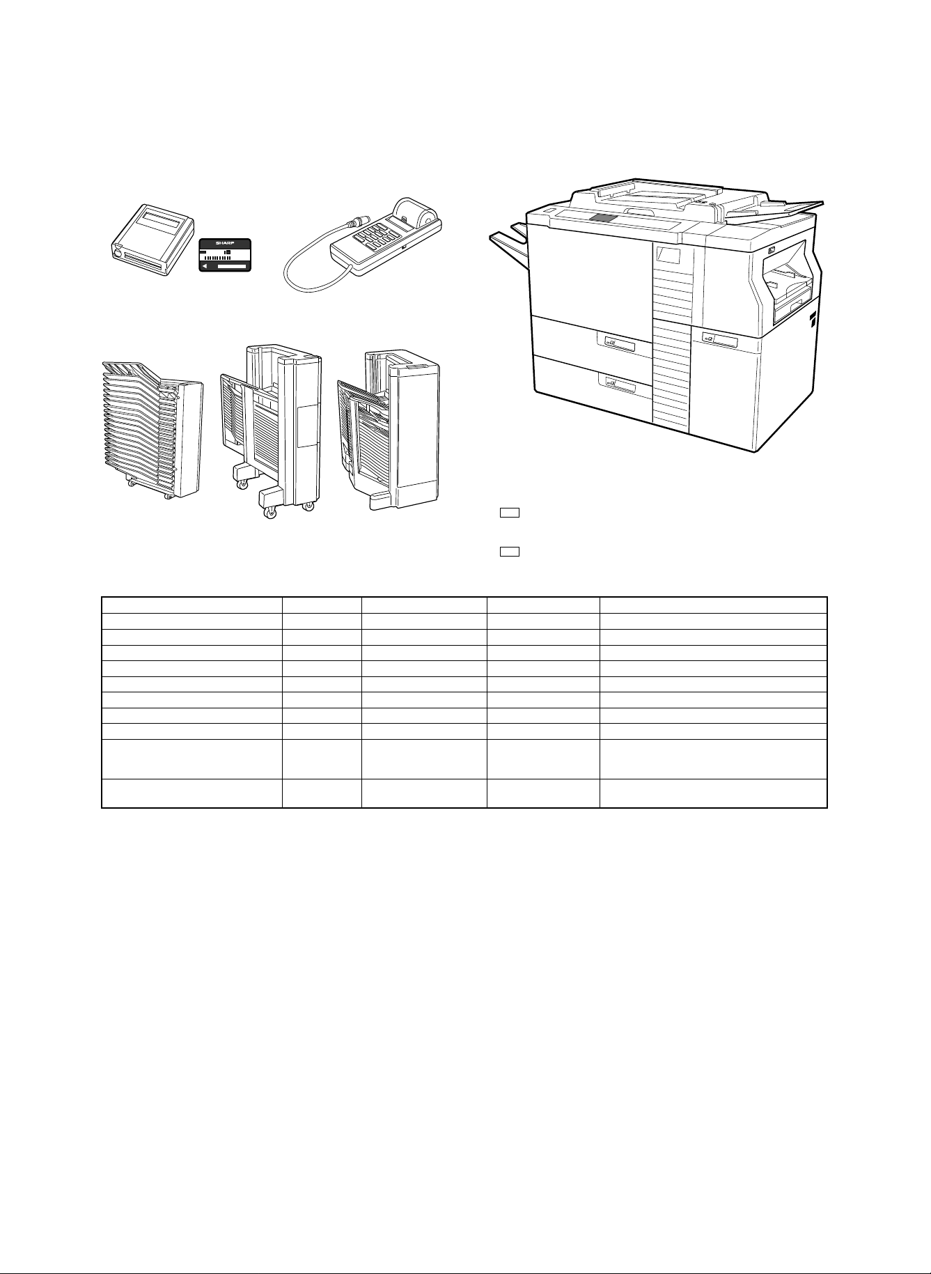
1. System configuration
COPY CARD
001
Card type auditor Commander
SF-EA11 SF-EA13
20-bin sorter 20-bin staple sorter 20-bin staple sorter
SF-S16 SF-S53 SF-S55
SD-2260 main body
Expansion RAM (2600 dept) (For internal auditor)
* DKIT-0321FCZZ
Communication interface board
* CPLTM4130FC53
Part name Model Common use model Power source Note
Copier body SD-2260
RADF (New) * Standard (New) Supplied from the copier.
20-bin sorter * SF-S16 SF-2050, SD-2060, etc. Supplied from the copier.
20-bin staple sorter * SF-S53 SF-2050, SD-2060, etc. Supplied from the copier.
20-bin staple sorter * SF-S55 (New) Supplied from the copier. Can be used only in SD-2260.
Card type department control counter * SF-EA11 SF-2050, SD-2060, etc. Supplied from the copier.
Commander * SF-EA13 SF-2050, SD-2060/3062, etc. Supplied from the copier.
Paper exit tray LSOU-0054FCG4 SF-2050, SD-2060, etc. Treated as a service part.
Expansion RAM for internal auditor * DKIT-0321FCZZ SD-2060/3062/2160 The standard capacity of the internal auditor is 500
Communication I/F board * CPLTM4130FC53 SD-2060/3062/2160 Treated as a service part with the frame. The part
departments. By installing this expansion RAM, 2600
departments are added to be 3100 departments in total.
without the frame (PWB unit) is CPLTM4132FC55.
* : Option
1 – 1
Page 4

2. Features
(1) High productivity
1 Large capacity tray, cassette
Air paper feed tray (3,300 sheets) × 1
Air paper feed tray (1,000 sheets) × 1
Paper cassette (250 sheets) × 1
Manual paper feed tray (100 sheets) × 1
2 RADF is equipped with the large capacity tray (100 sheets,
80g/m2).
3 Duplex copying of max. 100 sheets is possible. (The duplex tray
capacity: 100 sheets, 80g/m2) 50 sheets for A3 (11″ × 17″).
4 Large capacity toner hopper (Equivalent to 56K)
5 RADF realizes 100% efficiency of single copy from single docu-
ments.
6 The staple sorter of 50-sheets allows automatic after-process
(with the option sorter installed).
7 Unit structure
The employment of the unit structure allows quick recovery by
replacement of the unit in case of a trouble, shortening the recovery time.
8 Automatic copy density adjustment
This feature automatically adjusts the copy lamp voltage in each
copy mode depending on the copier conditions, eliminating the
need for copy density adjustment by the simulation.
(4) High picture quality
1 AICS (Active Image Control System)
The Sharp’s unique AICS (Active Image Control System) allows to
check toner concentration on the photoconductor drum by the
copier itself, correcting a change in density due to deterioration
automatically. This maintains high quality copies for a long period.
(2) High reliability
1 Air feed system
The air feed system allows smooth paper feed. It utilizes air pressure to separate paper without contact, stabilizing the paper transport force, reducing double feed and paper jam.
2 Auto recovery
In case of a paper jam, the trouble may be canceled by removing
the minimum number of paper. (The drive section of the copier is
divided into several sections, which are driven separately. In case
of a paper jam, transport is continued or stopped depending on
the jam position. By removing paper from the sections which are
not related to the paper jam, the trouble is canceled, reducing
paper jam treatment.)
3 Communication feature
Communication between the copier and the service center is possible through the telephone line. The serviceman can identify the
trouble position in advance to servicing, shortening the recovery
time. (Option)
4 Full frame structure
The frame of the machine is made of a strong structure, enabling
long-period use that is highly durable.
(3) The LCD screen with the backlight allows each
operations.
1 Key operator program
Use of the key operator program allows setting and adjustment of
the operation mode according to the office needs. The department
control counter is a standard provision.
1 – 2
Page 5

[2] SPECIFICA TIONS
1. Basic specifica tio ns
1) Type
Console
2) Copy system
Static electricity transfer, dry copier
3) Class
Segment 4
4) Target users
The target users of this model are high copy volume users such
as general offices and copy centers.
Monthly copy volume: Average 40,000 ∼ 50,000/month
(Min. 30,000/month, max. 200,000/month)
5) Machine life (Overhaul): 1200K
6) Size
1167 × 762 × 1080mm
1627 × 762mm (Occupying area) (With the paper exit tray and the
paper feed tray installed)
7) Weight
257 kg (567 lbs)
2. Copy performance
A. Original size
(1) Original table mode
Max. original size: A3 (11 × 17")
(2) RADF mode
Original size: A3 ∼ A5 (11 × 17" ∼ 5.5 × 8.5")
B. Copy paper size, weight, kinds
(1) A3 ∼ A5 (11 × 17" ∼ 5.5 × 8.5")
C. Copy mode
Auto mode
Photo mode (Variable in 9 steps)
Manual mode (Variable in 9 steps)
D. Copy magnification ratio
(1) Zoom mode
50 ∼ 200% (Variable in 1% increment )
(2) Fixed magnification ratios
AB series: 200/141/122/115/100/86/81/70/50 [%]
Inch series: 200/141/129/121/100/95/77/64/50 [%]
(Error ±0.9%)
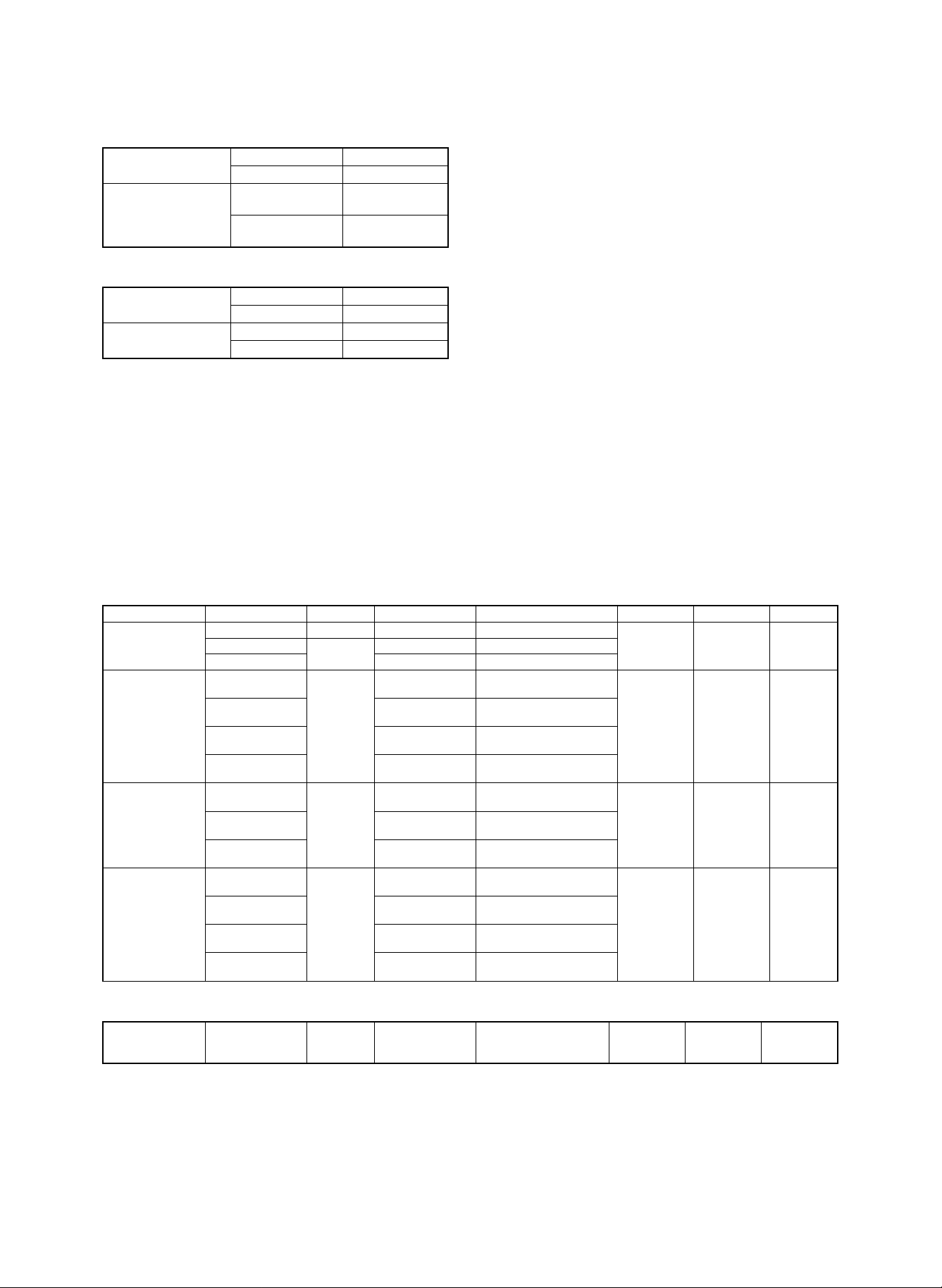
E. Copy speed
(1) Continuous copy speed
Unit (CPM)
Paper size Normal
A3 36 36 36
B4 41 39 41
A4 60 53 44
A4R 46 45 44
B5 60 58 44
B5R 46 45 44
11 × 17 36 36 36
8.5 × 14 41 39 41
8.5 × 11 60 53 44
8.5 × 11R 46 45 44
(2) First copy speed
Unit (sec), 8.5 × 11" or A4 paper
Non-RADF mode RADF mode
With sorter
P.F. unit
TRAY1 4.0 4.3 4.6 4.9
TRAY2 4.7 5.0 4.8 5.1
TRAY3 5.2 5.5 5.3 5.6
M.F TRAY 3.7 4.0 4.7 5.0
Cassette 3.6 3.9 4.7 5.0
Without
sorter
(SF-S55)
installed
(Reference
value)
Reduction
(50%)
Without
sorter
Enlargement
(200%)
With sorter
(SF-S55)
installed
(Reference
value)
F. Max. continuous copy quantity
999 sheets
G. Void area, image loss
Item Lead edge Rear edge
Image loss 1.0 ∼ 4.5 mm —
Void area 1.0 ∼ 3.0 mm 1.0 ∼ 4.0 mm
Image shift for paper 0±1.5 mm —
H. Resolution
Copy magnification ratio Copy center Corners
100% 5.0 lines/mm 4.5 lines/mm
101 ∼ 200% 5.0 lines/mm 4.5 lines/mm
90 ∼ 99% 4.5 lines/mm 4.0 lines/mm
64 ∼ 89% 3.6 lines/mm 3.2 lines/mm
50 ∼ 63% 3.2 lines/mm 2.8 lines/mm
2 – 1
Page 6
I. Center shift
Original table mode
Overall (RADF mode)
Single ±2.0 mm
Duplex ±2.0 mm
Single S → S
D → S
Duplex S → D
D → D
±3.0 mm
±4.0 mm
±3.0 mm
±4.0 mm
J. Skew feed
Copier
(Original table mode)
Overall (RADF mode)
Single 2.0mm or less
Duplex 2.0mm or less
S → S, S → D 3.0mm or less
D → S, D → S 3.0mm or less
K. Duplex multi copy
Max. 100 sheets, however 50 sheets for A3 (11 × 17")
3. Operational (hardware) specifications
A. Paper feed section
(1) Paper feed system
3 paper feed tray (Air paper feed system)
1 paper cassette (Roller paper feed system)
Multi manual paper feed (Roller paper feed system)
(2) Paper capacity, paper weight, paper size, paper kinds
Paper feed section Destination Capacity Paper size Detection size Paper weight Size selection Type
No. 1 paper feed tray
No. 2/3 paper feed tray
Cassette paper feed
Manual paper feed tray
Japan 3,300 sheets A4, B5 A4, B5
EX AB series
Ex Inch series 8.5 × 11 8.5 × 11
Japan
Inch series 11 × 17 ∼ 8.5 × 11
EX other AB series A3 ∼ A4
Australia, New Zealand A3 ∼ A4
Japan
EX AB series A4, A4R, B5, B5R
EX inch series A4, A4R, B5, B5R
Japan
Inch series 8.5 × 5.5 ∼ 11 × 17 11 × 17, 8.5 × 14, 8.5 × 11
EX other AB series A3 ∼ A5 A3, B4, A4, A4R, A5
Australia, New Zealand A3 ∼ A5 A3, B4, A4, A4R, A5
3,000 sheets
1,000 sheets
250 sheets
100 sheets
A4 A4
A3 ∼ B5 A3, B4, A4, B5, A4R, B5R,
A4
8.5 × 14, 8.5 × 11
8.5 × 13, 8.5 × 11
A4, A4R, B5, B5R
8.5 × 11, 8.5 × 11R
8.5 × 11, 8.5 × 11R
8.5 × 11, 8.5 × 11R
A3 ∼ A5 A3, B4, A4, A4R,
8.5 × 11, 8.5 × 14
11 × 17, 8.5 × 14, 8.5 × 11, 8.5
× 11R, A4, (8.5 × 13)
A3, B4, A4, A4R
8.5 × 11, 8.5 × 14
A3, B4, A4, A4R
216 × 279, 216 × 330 (mm)
A4, A4R, B5, B5R
8.5 × 11
A4, A4R
8.5 × 11
A4,
8.5 × 11, 8.5 × 11R
B5R, 8.5 × 11
8.5 × 11R, 8.5 × 5.5, (8.5 × 13)
8.5 × 11
216 × 279, 216 × 330 (mm)
60 ∼ 90 g/m
16 ∼ 24 lbs
60 ∼ 128 g/m
16 ∼ 32 lbs
60 ∼ 128 g/m
16 ∼ 32 lbs
cover paper
(176g)/index
paper (200g)
50 ∼ 128 g/m
13 ∼ 32 lbs
cover paper
(176g)/
index paper
(200g) * 1
2
2
2
2
Guide change
(by serviceman)
Universal
Universal
Universal
*1: Manual tray
Special paper (OHP, etc.)
Duplex unit All destinations 100 sheets,
50 sheets for
A3 (11 × 17")
A3 ∼ B5
(11 × 17 ∼ 8.5 × 11) —
60 ∼ 90 g/m
16 ∼ 24 lbs —
2
Air paper feed
system
Air paper
feed system
Air paper
feed system
Roller paper
feed system
Roller paper
feed system
2 – 2
Page 7

B. Original table section
(1) Max. original size
A3, 11 × 17"
(2) Original reference position
Left center reference
(3) Original size detection
System: Photo transmission sensor system
Detection size:A3, B4, A4, A4R, B5, B5R
C. RADF section
(1) Paper feed system
Roller paper feed system
(2) Transport system
Belt transport system
(3) Reverse system
By the reverse gate and the roller.
(4) Original tray capacity (paper feed, paper exit tray)
Max. 100 sheets (80g/m2)
(5) Original size
A3 ∼ A5 (11 × 17" ∼ 5.5 × 8.5)
(6) Original paper weight
Single mode: Japan - 35 ∼ 128g/m2 (35 ∼ 50g/m2 for thin paper mode)
EX - 50 ∼ 128g/m2, 13 ∼ 32 lbs
Duplex mode: 50 ∼ 128g/m2, 13 ∼ 32 lbs (A5 ∼ A4)
50 ∼ 110g/m2, 13 ∼ 29 lbs (A5 ∼ A3)
(7) Original replacement speed
60 sheets/min (Max.) (A4/8.5 × 11")
(8) Operation mode
• Duplex/single
• Normal paper/thin paper
• Normal/stream mode
(9) Original size detection
1) Original size detection by the original tray
Detection by the detector on the original tray (The paper width is
detected by the analog sensor, and the paper length by the paper
length detector.)
(Detection size)
Japan: A3, B4, A4, B5, A4R, B5R, 8,5 × 11, 8.5 × 14
EX inch series: 11 × 17, 8.5 × 14, 8.5 × 11, 8.5 × 11R, 8.5 × 5.5,
A4 (8.5 × 13 possible by SIM setting)
German/UK: A3, B4, A4, A4R, A5, 8.5 × 11, 8,5 × 14
Australia: A3, B4, A4, A4R, A5, 216 × 179, 216 × 330 (mm)
2) Original size detection by the original transport roller rotation
(Detection size)
Japan: A3, B4, A4, B5, A4R, B5R
EX inch series: 11 × 17, 8.5 × 14, 8.5 × 11, 8.5 × 11R, 8.5 × 5.5
(8.5 × 13 possible by SIM setting)
German: A3, B4, A4, A4R, A5
Australia: A3, B4, A4, A4R, A5, 216 × 330 (mm)
D. Optical section
(1) Exposure system
Exposure section (lamp) scanning slit exposure system
(2) Zooming system
Lens moving system
(3) Lens specifications
Composition: 1-group, 4-lens
Fixed focus lens F: 5.6, f: 220mm
(4) Exposure mode
Auto mode (Synchronized with scanning operation to measure the
center of 100mm wide for automatic adjustment of the copy lamp
voltage.)
Manual mode
Photo mode
(5) Copy lamp specifications
Halogen lamp
(100V system) 85V, 220W
(200V system) 170V, 260W
(6) Correction
Automatic correction of the copy lamp voltage.
E. Image forming section
(1) Photoconductor section
1) Type: OPC
2) Size: 100 ϕ
3) Life: 250K
4) Humidity control by the surface heater
(2) Charger section
1) Main charger
Scorotron system (screen grid, saw tooth electrode)
2) Transfer charger
Corotron system by wire
(3) Separation section
1) System: Separation by the separation charger and the separation
pawl
2) Separation charger
Corotron system by wire
3) Separation pawl life
4) Pre-transfer discharger
Corotron system by wire
(4) Developing section
1) System: Magnetic brush developing system
2) 2-component development (Developer: Positive charging, toner:
negative charging)
3) Developing bias voltage: DC–220V
4) Developer
Capacity: 850g/bag × 2 bags (= 1.7 kg)
Life: 250K
Type: Ferrite type
(5) Toner hopper section
Capacity 930g (Equivalent to 28K with 6% density originals)
2 – 3
Page 8
(6) Cleaning section
Cleaning by the brush and the pressure contact blade system
Cleaning blade life: 125K
(7) Correction
Main charger grid voltage correction
Photoconductor drum OPC membrane wear sensitivity correction
I. Paper exit section
Tray capacity 250 sheets
Full detection feature
J. Waste toner collection section
Capacity: 1750g (125K, with 6% density originals)
F. Fusing section
(1) System
Roller pressure system
(2) Roller type
Teflon roller (heat roller) life
500K
Silicon rubber roller (pressure roller) life
250K
(3) Heater lamp
Destination Main Sub
Japan 15A spec. 750W 660W
Japan 20A spec. 1075W 700W
EX 100V series 1100W 700W
EX 200V series 1150W 650W
(4) Fusing temperature
Destination
Japan 15A spec. 205˚C 205˚C
Japan 20A spec. 200˚C 200˚C
EX inch series 200˚C 180˚C
EX AB series 205˚C 205˚C
Normal Duplex
(5) Separation system
Forced separation by the separation pawl
Upper separation pawl life: 250K
Lower separation pawl life: 250K
(6) Cleaning system
Cleaning by the cleaning roller
Upper cleaning roller life: 125K
Lower cleaning roller life: 125K
Copy mode
K. Jam recovery time
Within 5 sec (When jam canceling is made within 60 sec in case of a
jam outside the fusing section.)
L. Communication function
Remove communication function (RS232C)
M. Warm-up time
Japan: About 10 min (15A specification), about 5 min (20A specifica-
tion)
EX: About 5 min
N. Operating voltage, power consumption
(Power consumption)
Max.
Japan EX
15A 20A
1500W 1800W
Average 1200W (During copying)
Power save mode
(Pre heat mode (Fusing temperature fall)) 236Wh or less
Stand-by mode (Ready state) 332Wh or less
Power shut off (Power switch OFF) 15Wh or less
(Operating power) (Fluctuation)
Within 10% of the rated voltage, within ±2% of the rated r\frequency
1900W
O. Noise
Sound power level Sound pressure level
During copying 75db or less 63db or less
Standby 55db or less 40db or less
G. Switchback section
(1) System
Transport speed variable system by the reverse gate and the stepping motor
H. Duplex section
(1) Paper feed system
Air paper feed system
(2) Paper capacity, paper weight, paper size, paper kinds
(Paper weight, size)
A3 ∼ B5 (11 × 17 ∼ 8.5 × 11) However, f ixed size.
60 ∼ 90g/m
(Paper capacity)
Max. 100 sheets, however 50 sheets for A3 (11 × 17)
2
P. Electromagnetic noise
Japan: Electromagnetic wave regulations VCCI
USA: FCC
Europe/Australia/South Africa: CISPR
2 – 4
Page 9
Q. Additional functions
Japan SEC SECL SEEG SUK SCA Others
Auto paper selection (APS) || (Only when RADF is used)
Auto magnification ratio selection (AMS)
Binding margin Shift width: 9mm, /4 inch (with adjustment function)
1-set 2-copy | (Enlargement impossible)
Edge erase | (Edge erase/center erase/edge + center erase)
Cover insertion | (Cover paper/back cover/ front, back cover (duplex copy possible))
Index insertion | (Duplex copy possible/max. 18 pages insertion possible)
OHP index |
Job memory | (9 ways)
Auditor | (Standard 500 departments. 3,,100 departments when expanded. DKIT-0321FCZZ required.)
Key operator program |
Communication | (I/F PWB is treated as a service part.)
Toner save mode | (Set by the simulation.) |
Auto tray switching |
Installation tray priority selection ✕
Pre-heat function | (Selection by the key operator program)
Auto power shut off (EnergyStar compliance) | (OFF mode available
Power save mode ✕ |
|
Adjustment width: 0, 3, 6, 9, 12, 15mm/0, 1/8, 1/4, 3/8, 1/2, 5/8 inch
Edge erase adjustment width: 0 ∼ 6, 6 ∼ 12, 1 2 ∼ 18mm/ 0 ∼ 1/4, 1/4 ∼ 1/2, 1/2 ∼ 3/4 inc h
Center erase adjustment width: 10, 15, 20mm/2/5, 3/5, 4/5 inch
by the simulation)
| (Only when RADF is used)
AMS is used by document size detector of RADF tray.
✕
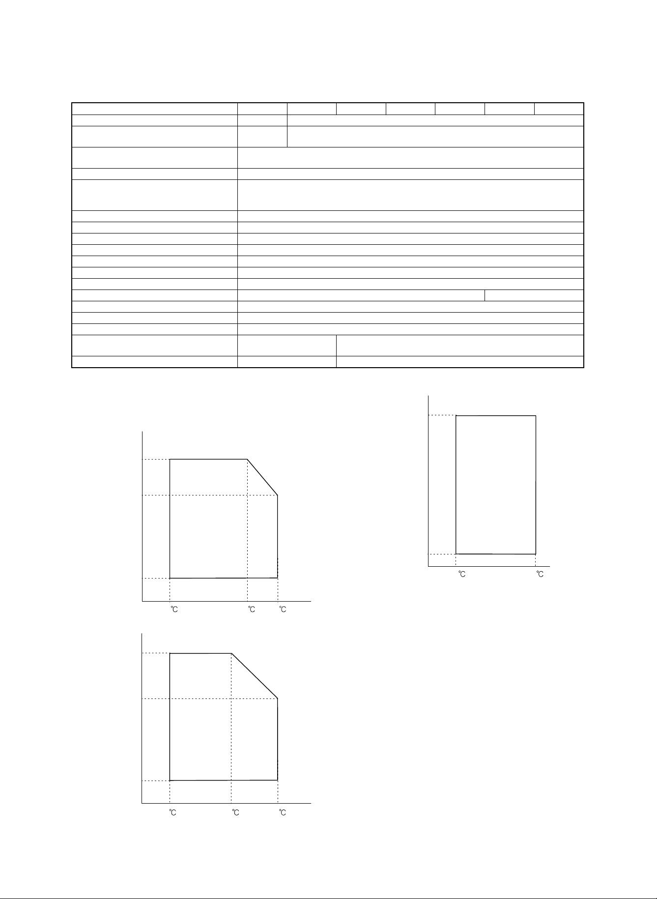
R. Environmental conditions
(Standard conditions)
Temperature: 20 ∼ 25˚C, humidity: 65 ± 5% RH
(Operational condition)
Humidity (RH)
85%
60%
20%
15
(Transport conditions)
Humidity
(RH)
90%
60%
20%
-5
30
30 35
45
(Consumable parts storage conditions )
(Supply storage conditions)
Humidity
(RH)
90%
10%
-10
4. Option specifications
A. Sorter
• 20-bin sorter (SF-S16)
Number of bins: 20 bins
Capacity: Non-sorting 100 sheets
Sorting 50 sheets
Grouping 30 sheets
Sortable size: Japan; all detectable sizes
USA; All detectable size excluding 5.5 ×
8.5
Canada; All detectable size excluding 5.5 ×
8.5
UK: All detectable sizes excluding A5
Europe; All detectable sizes excluding A5
Australia; All detectable sizes excluding A5
2 – 5
40
Page 10

Power: 24V (Supplied from the copier)
Copier weight: 26.5kg
Dimensions: 512 (W) × 520 (D) × 883 (H)mm
• 20-bin staple sorter (SF-S53)
Number of bins: Non-sort bin - 1 bin, sort bin - 20 bins
Capacity: Non-sorting 250 sheets
Sorting: 11 × 17, 8.5 × 14, 8.5 × 13, A3, B4;
25 sheets
8.5 × 11, 8.5 × 11R, A4, A4R, B5;
50 sheets
Grouping: 11 × 17, 8.5 × 14, 8.5 × 13, A3, B4;
25 sheets
8.5 × 11, 8.5 × 11R, A4, A4R, B5;
30 sheets
Sortable size: Japan; All the detectable sizes
USA; All the detectable sizes excluding 5.5
× 8.5"
Canada; All the detectable sizes excluding 5.5
× 8.5"
UK; All the detectable sizes excluding A5
Europe: All the detectable sizes excluding A5
Australia; All the detectable sizes excluding A5
Staple sortable
sizes:
Staple capacity: 50 sheets
Staple position: Left upper corner, slant, one position
Stapler cartridge: 1 cartridge - 5000 staplers
Stapler detection: Available
Alignment: 2.5mm
Bin shift time: About 15 sec (20 bins → Bin home position)
Power source: 24V (Supplied from the copier)
Max. power consumption: 75W or less
Weight: 37kg
Dimensions: 465 (W) × 597 (D) × 926 (H) mm
Japan; All the detectable sizes excluding
B5R
USA; All the detectable sizes excluding 5.5
× 8.5"
Canada; All the detectable sizes excluding 5.5
× 8.5"
UK; All the detectable sizes excluding A5
Europe: All the detectable sizes excluding A5
Australia; All the detectable sizes excluding A5
• 20-bin multi position staple sorter (SF-S55)
Number of bins: Non-sort - 1 bin, sort bin - 20 bins
Capacity: Non-sorting 50 sheets
Sorting: 11 × 17, 8.5 × 14, 8.5 × 13, A3, B4;
25 sheets
8.5 × 11, 8.5 × 11R, A4, A4R, B5, A5;
50 sheets
Grouping: 11 × 17, 8.5 × 14, 8.5 × 13, A3, B4;
25 sheets
8.5 × 11, 8.5 × 11R, A4, A4R, B5;
30 sheets
Sortable size: Japan; All the detectable sizes including A5
USA; All the detectable sizes excluding
Canada; All the detectable sizes
UK; All the detectable sizes
Europe: All the detectable sizes
Australia; All the detectable sizes
Staple sortable Japan; All the detectable sizes
sizes: USA; All the detectable sizes excluding 5.5
× 8.5"
Canada; All the detectable sizes excluding 5.5
× 8.5"
UK; All the detectable sizes excluding A5
Europe: All the detectable sizes excluding A5
Australia; All the detectable sizes excluding A5
Staple capacity: 50 sheets
Staple position: Corner 1 position, 2 positions, 1 position
Stapler cartridge: 1 cartridge - 5000 staplers
Stapler detection: Available
Alignment: 2.5mm
Bin shift time: about 15 sec (20 bins → Bin home position)
Power source: 24V (Supplied from the copier)
Max. power consumption: 100W or less
Weight: 56kg
Dimensions: 564 (W) × 609 (D) × 986 (H) mm
B. Auditor,commander
MODEL DESCRIPTION
CARD COUNTER (Read the department code by
SF-EA11
SF-EA13 COMMANDER (Setting the department)
SF-EA11 YES NO YES NO 200
SF-EA13 NO YES NO YES
Card (Used for SF-EA11)
SF-EA11A 1 to 30 30
SF-EA11B 31 to 100 70
SF-EA11C 101 to 200 100
Combination of use
SF-EA11 and SF-EA13
printed on card and memory of the copy count is
stored to insided memory.)
Memory Printer Display Key
Dept number Number of card
TOTAL 200 200
Maximum number
of department
C. Expansion memory (For the international auditor)
DKIT-0321FCZZ (3100 department expansion)
D. Key sheet and operation manual kits
English SD-260SE
German SD-260SG
French SD-260SF
Dutch SD-260SH
Spanish SD-260SS
Italian SD-260SI
2 – 6
Page 11
1 Two packages are used. (SD-365ND) × 10 = SD-365MD
1 (SD-365NT) × 10 = SD-365MT
(SD-365NT × 10)
(SD-365ND × 10)
(365RU) × 10 = 365UR, order reception as SD=365UR.
(360RL) × 10 = 360LR, order reception as SD-360LR.
No. 6, 8, 9: Common to SD-2060/3062.
1 (360BL) × 10 = 360CB, order reception as SD-360CB.
1
(SD-360BL × 10)
1
(SD-365RU × 10)
10 Use for SF-S53
(SD-360RL × 10)
Common to SD=2060/3062.
1 (365CP) × 5 = 365CK, order reception as SD-365CK.
(SD-SC20 × 5)
(SD-365CP × 5)
[3] CONSUMABLE PARTS
Fusing separation pawl (Upper) × 4
Fusing gear (New) × 1
Heat insulation bush (New) × 2
Fusing separation pawl (Lower) × 4
Developer Developer (New) (0.85Kg) × 10 250K SD-365MD
Toner Toner cartridge (New) (0.93Kg) × 10 28K SD-365MT
1 Drum OPC drum (New) × 1 250K SD-365DR 6 Similar to the drum for SD-2060/3062.
2
3
4 Upper heat roller kit Upper heat roller (New) × 1 500K SD-365UH 5 Similar to the upper heat roller kit for SD-2060/3062.
(USA)
No. Name Content Life Product name Package Remark
1. OPC drum, developer, toner, maintenance kit
5 Lower heat roller kit Lower heat roller × 1 250K SD-360LH 5 Similar to the lower heat roller kit for SD-2060/3062.
6 Cleaner blade Cleaner blade × 10 125K SD-360CB
7 Upper cleaning roller Upper cleaning roller (New) × 10 125K SD-365UR
8 Lower cleaning roller Lower cleaning roller × 10 125K SD-360LR
9 Waste toner bottle Waste toner bottle × 1 125K SD-360TB 5
10 Staple cartridge Cartridge × 5 5000 SD-LS20
3 – 1
(Drum separation pawl × 2)
(Charging blade unit × 1)
11 Convenience parts kit 365CP × 5 250K SD-365CK
(Screen grid (New) × 1)
(Toner reception seal × 1)
Waste toner bottle (125K), screen grid (250K), charging blade unit (250K), drum separation pawl (250K), and toner reception seal (250K) are supplied also as service parts.
* Charger wire (250K), Ozone filter (500K), DV seal (500K), and CL brush roller (500K) are supplied as service parts.
Page 12

1 Two packages are used. (SD-365ND) × 10 = SD-365MD
1 (SD-365NT ) × 10 = SD-365MT
10 Use for SF-S55
(SD-365ND × 10)
(SD-365NT × 10)
(SD-SC20 × 5)
Fusing separation pawl (Upper) × 4
Fusing gear (New) × 1
Heat insulation bush (New) × 2
Fusing separation pawl (Lower) × 4
Waste toner bottle × 1
Upper cleaning roller (New) × 1
Lower cleaning roller × 1
Charging blade unit × 1
Toner reception seal × 1
Screen grid (New) × 1
No. Name Content Life Product name Package Remark
(Canada)
Developer Developer (New) (0.85Kg) × 10 250K (× 5) SD-365MD
Toner Toner cartridge (New) (0.93Kg) × 10 28K (× 10) SD-365MT
1 Drum OPC drum (New) × 1 250K SD-365DR 6 Similar to the drum for SD-2060/3062.
2
3
4 Upper heat roller kit Upper heat roller (New) × 1 500K SD-365UH 5 Similar to the upper heat roller kit for SD-2060/3062.
5 Lower heat roller kit Lower heat roller × 1 250K SD-360LH 5 Similar to the lower heat roller kit for SD-2060/3062.
6 125KPM kit Cleaner blade × 1 125K SD-365KA 5
7 250KPM kit Drum separation pawl × 2 250K SD-365KB 5 Common to 250KPM kit for SD-2060/3062.
3 – 2
8 Staple cartridge Cartridge × 5 5000 SD-LS20
Page 13

SD-2060/3062.
(SD-365DV) × 10 = SD-365LD
1 Two packages are used.
1 (SD-365T) × 10 = SD-365LT
10 Use for SF-S55
(SD-365DV × 10)
(SD-365T × 10)
(SD-SC20 × 5)
Fusing separation pawl (Upper) × 4
Fusing gear (New) × 1
Heat insulation bush (New) × 2
Fusing separation pawl (Lower) × 4
Waste toner bottle × 1
Upper cleaning roller (New) × 1
Lower cleaning roller × 1
Charging blade unit × 1
Toner reception seal × 1
Screen grid (New) × 1
1 Drum OPC drum (New) × 1 250K SD-365DM 6 Similar to the drum for
No. Name Content Life Product name Package Remark
(Europe) SEEG, SUK
2 Developer Developer (New) (0.85Kg) × 10 250K (× 5) SD-365LD
3 Toner Toner cartridge (New) (0.93Kg) × 10 28K (× 10) SD-365LT
4 Upper heat roller kit Upper heat roller (New) × 1 500K SD-365UH 5 Similar to SD-2060/3062.
5 Lower heat roller kit Lower heat roller × 1 250K SD-360LH 5 Similar to the lower heat roller kit for SD-2060/3062.
6 125KPM kit Cleaner blade × 1 125K SD-365KA 5
7 250KPM kit Drum separation pawl × 2 250K SD-365KB 5
3 – 3
8 Staple cartridge Cartridge × 5 5000 SD-LS20
Page 14

1 Two packages are used. (SD-365SD) × 10 = SD=365CD
1 (SD-365SI) × 10 = SD-365CI
10 Use for SF-S55
(SD-365SD × 10)
(SD-365ST × 10)
(SD-SC20 × 5)
Fusing separation pawl (Upper) × 4
Fusing gear (New) × 1
Heat insulation bush (New) × 2
Fusing separation pawl (Lower) × 4
Waste toner bottle × 1
Upper cleaning roller (New) × 1
Lower cleaning roller × 1
Charging blade unit × 1
Toner reception seal × 1
Screen grid (New) × 1
Developer Developer (New) (0.85Kg) × 10 250K (× 5) SD-365CD
Toner Toner cartridge (New) (0.93Kg) × 10 28K (× 10) SD-365CT
1 Drum OPC drum (New) × 1 250K SD-365DR 6 Similar to the drum for SD-2060/3062.
2
3
No. Name Content Life Product name Package Remark
(Asia, Middle & South America)
4 Upper heat roller kit Upper heat roller (New) × 1 500K SD-365UH 5 Similar to the upper heat roller kit for SD-2060/3062.
5 Lower heat roller kit Lower heat roller × 1 250K SD-360LH 5 Similar to the lower heat roller kit for SD-2060/3062.
6 125KPM kit Cleaner blade × 1 125K SD-365KA 5
7 250KPM kit Drum separation pawl × 2 250K SD-365KB 5 Similar to 250KPM kit for SD-2060/3062.
3 – 4
8 Staple cartridge Cartridge × 5 5000 SD-LS20
Page 15

1 Two packages are used. (SD-365DV) × 10 = SD=365LD
1 (SD-365T) × 10 = SD-365LT
10 Use for SF-S55
(SD-365DV × 10)
(SD-365T × 10)
(SD-SC20 × 5)
Fusing separation pawl (Upper) × 4
Fusing gear (New) × 1
Heat insulation bush (New) × 2
Fusing separation pawl (Lower) × 4
Developer Developer (New) (0.85Kg) × 10 250K (× 5) SD-365LD
Toner Toner cartridge (New) (0.93Kg) × 10 28K (× 10) SD-365LT
1 Drum OPC drum (New) × 1 250K SD-365DM 6 Similar to the drum for SD-2060/3062.
2
3
No. Name Content Life Product name Package Remark
(Australia, New Zealand, Middle East, Africa)
4 Upper heat roller kit Upper heat roller (New) × 1 500K SD-365UH 5 Similar to the upper heat roller kit for SD-2060/3062.
5 Lower heat roller kit Lower heat roller × 1 250K SD-360LH 5 Similar to the lower heat roller kit for SD-2060/3062.
Waste toner bottle × 1
Upper cleaning roller (New) × 1
Lower cleaning roller × 1
Charging blade unit × 1
Toner reception seal × 1
Screen grid (New) × 1
6 125KPM kit Cleaner blade × 1 125K SD-365KA 5
7 250KPM kit Drum separation pawl × 2 250K SD-365KB 5 Similar to 250KPM kit for SD-2060/3062.
3 – 5
8 Staple cartridge Cartridge × 5 5000 SD-LS20
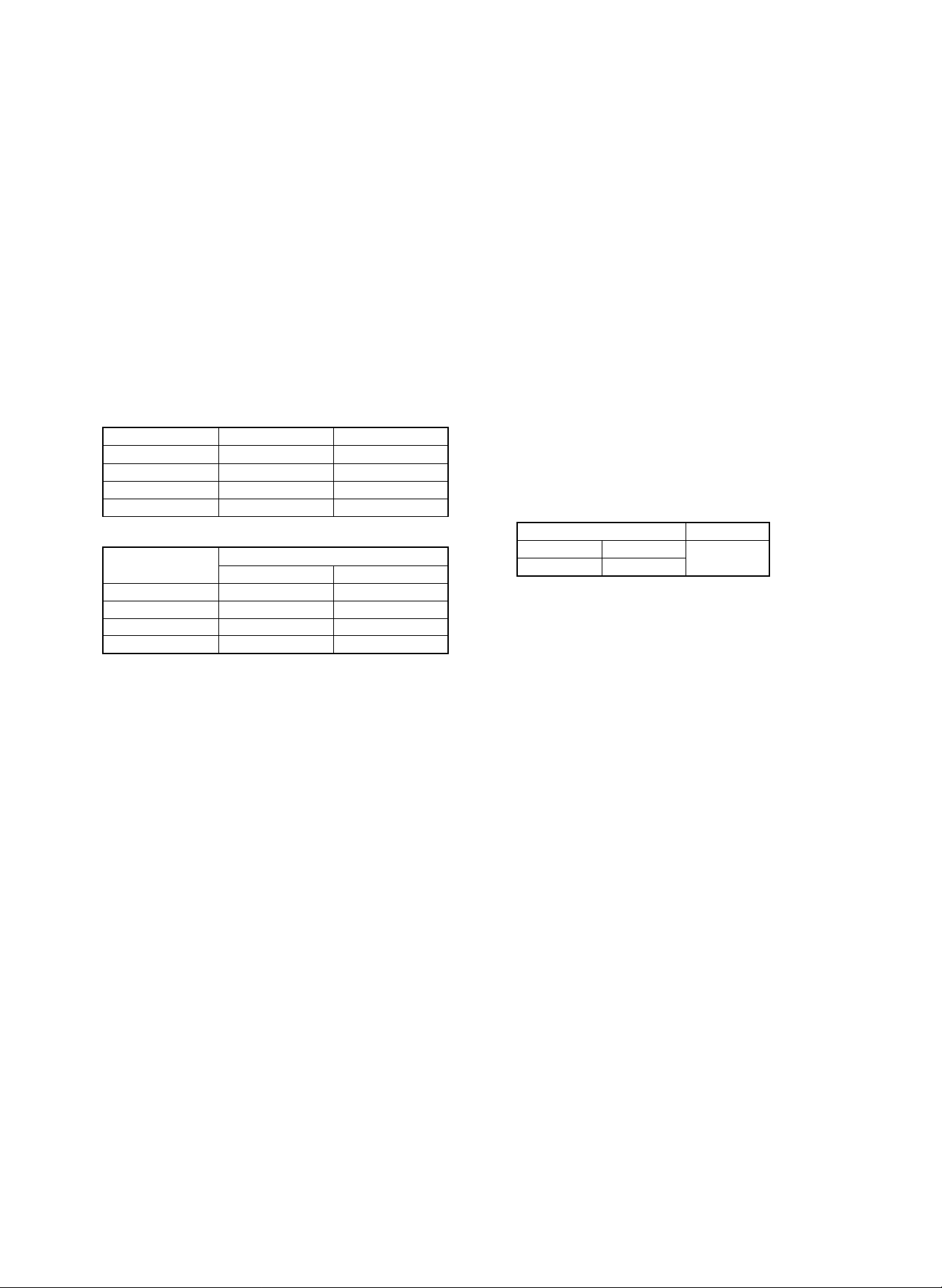
Page 16
Compatibility with SD-2260/3062/2060/2160
Compatibility with
SD-2260/3062/2060
Photoconductor drum New
Developer New 0.85kg Two packs are used
Toner New 930g Two packs can be
Upper heat roller New
Lower heat roller Available
Cleaner blade Available
Upper/lower cleaning
roller
Drum separation pawl Available
Upper fusing
separation pawl
Lower fusing
separation pawl
Charging blade unit Available
Waste toner bottle
*
New Lower cleaning roller
Available
Available
Available
* : One for SD-2260 (New) is applicable to SD-3062/2060/2160.
One for SD-3062/2060/2160 is not applicable to SD-2260.
Capacity Remark
for once.
supplied for once.
(compatible)
2. Copy paper
The following conditions for copy quality and transportability of PPC
paper must be satisfied. The values are at temperature of 20 ±1˚C
and 65 ±2% RH.
Item Standard
Weight 56 ∼ 80g/ m
Smoothness Face: 20 sec or above (BEKK method)
Back: 20 sec or above (BEKK method)
Rigidness Length 17cm or above, width 13cm or
above (CLARK method)
Thickness 75 ∼ 110µ
Dimensions Standard dimensions ± 1mm (5/128")
B4 (257 ±1 × 364±1mm)
B5 (182 ±1 × 257±1mm)
B6 (128 ±1 × 182±1mm)
A3 (297 ±1 × 420±1mm)
A4 (210 ±1 × 297±1mm)
A5 (148 ±1 × 210±1mm)
A6 (105 ±1 × 148±1mm)
11" ±5/128 × 17" ±5/128 inch
8.5" ±5/128 × 14" ±5/128 inch
8.5" ±5/128 × 11" ±5/128 inch
5.5" ±5/128 × 8.5" ±5/128 inch
8.5" ±5/128 × 13" ±5/128 inch
2
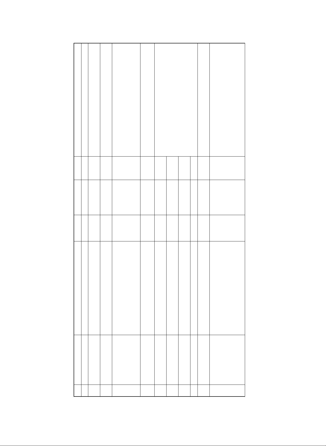
3. Environment conditions
A. Transport conditions
1) Transport condition
(%)
100
90%
80
60
40
Humidity
20
10%
0
-30 -20 -10 0 20 30 40 50 60
10
Temperature
2) Storage condition (packed conditions)
100
90
80
70
(%)
60
50
40
Humidity
30
20
10
Temperature
B. Use conditions
(%)
100
90%
80
60
Use envi-
40
Humidity
20
10%
0
-30 -20 -10 0 20 30 40 50 60
15
ronment
conditions
10
Temperature
30
40
85%
35
45
60%
90%
60%
40 90%
40
10%
50403020100-10-20
3 – 6
Page 17
C. Life (packed conditions)
Photoconductor drum (36 months from the production month)
Developer, toner (24 months from the production month)
B. Developer, toner
1 2 3 4 5 6-7
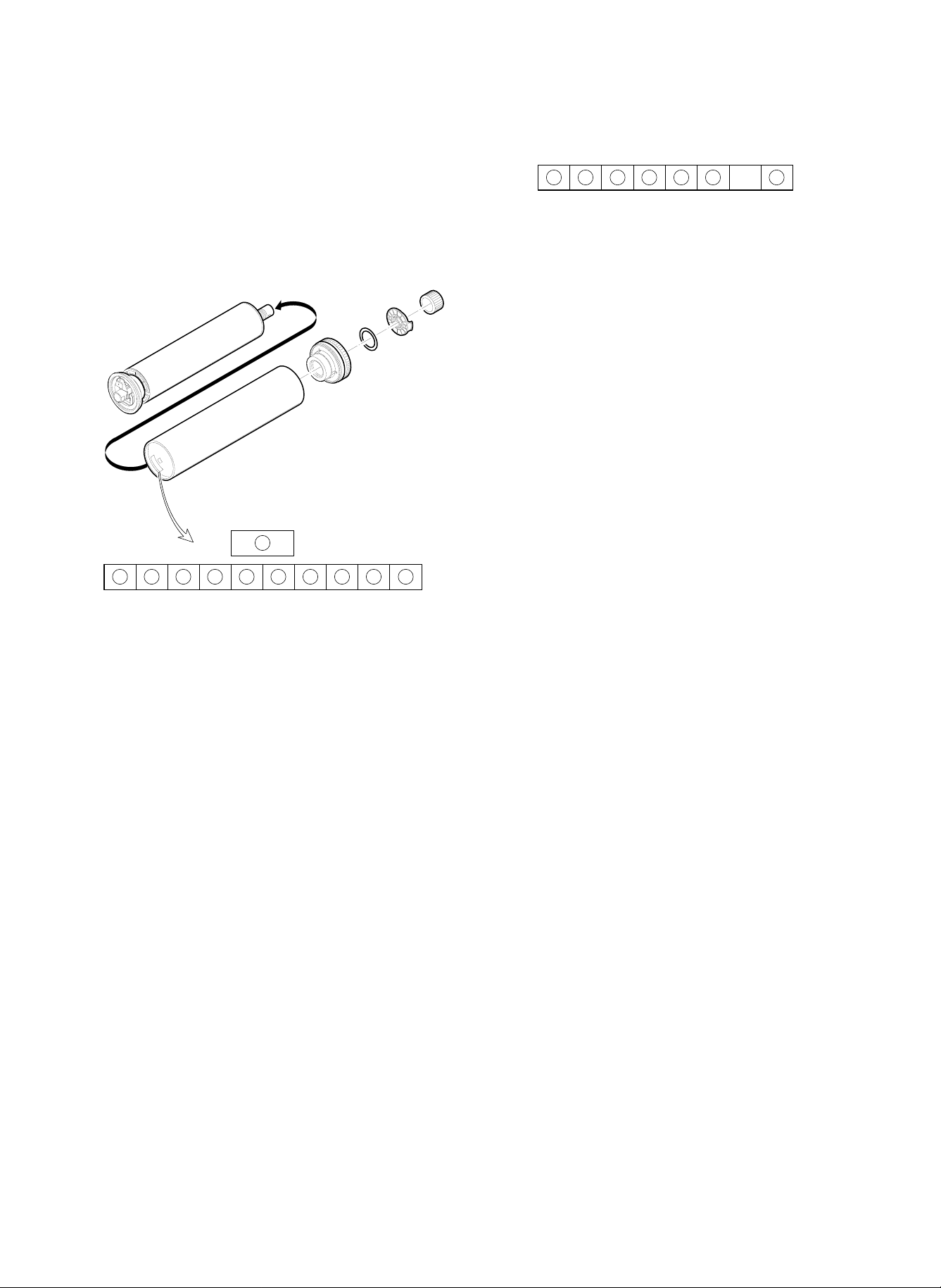
4. Production number identification
A. Photoconductor drum
11
1 2 3 4 5 6 7 8 9 10
1 Numeral
Shows the sensitivity of the photoconductor.
2 3 Alphabet
Shows the applicable model. AF for this model.
4 Numeral
Shows the end digit of the production year.
5 Numeral or X, Y, Z
Shows the production month.
X stands for October, Y November, and Z December.
6 Numeral
Shows the production lot.
7 Numeral
Shows the distinction of sub lot.
8 Numeral or X, Y, Z
Shows the packing month.
X stands for October, Y November, and Z December.
9 F Numeral
Shows the packing day.
G Numeral or alphabet
Shows the product name of the drum.
1 , 2 Alphabet
SF stands for toner, and SH for developer.
3 Numeral, alphabet
Shows the production month. O stands for October, Y November, and Z December.
4 , 5 Numeral
Shows the production day.
6 Numeral
Shows the end digit of the production year.
7 Alphabet
Shows the production batch.
Though the shapes of the photoconductor drum, developer, toner,
and the fusing section cleaning roller are similar to those of the SD2060, they are not compatible with each other.
The differences are as follows:
1) Photoconductor drum
If installed erroneously, the error code F2 is displayed.
2) Toner
The port shape of the toner bottle differs to prevent against erro-
neous installation.
The characteristics of toner differ from each other. The proper
toner must be used to obtain stable picture quality at proper density.
3) Developer
Proper developer must be used to obtain stable picture quality at
proper density.
4) Fusing section cleaning roller
(Upper cleaning roller)
(Lower cleaning roller)
3 – 7
Page 18

[4] SETUP
Setup list
No. Item No. Content Method Check
1 Installation environment
check
2 Delivery 1 Facility, equipment, man power Use a fork lift. (If a fork lift is not used, 6 men
3 Unpacking Remove the protection material.
4 Lock release 1 Scanner unit
5 Parts setup 1 Cleaning roller (2 pcs.) (Fusing unit)
6 Option setup 1 Sorter (SF-S55/53/16)
7 Consumable parts setup 1 Photoconductor drum (Europe only)
8 Cleaning 1 Main charger unit
9 Operation setting 1 Separation charger voltage setting
10 Image correction
setting/check
11 Image density sensor,
photoconductor drum mark
sensor check (adjustment)
1 Delivery space
2 Installation space
3 Power (Capacity, fluctuation, safety)
4 Floor strength
5 Direct sunlight, dust, temperature, humidity,
gases, chemicals
power is required.)
2 Delivery form Transported in packed condition.
2 No. 4/5 mirror unit
3 Lens unit
4 Paper feed tray (No. 1, 2, 3)
5 Paper feed cassette
6 Photoconductor drum protection sheet
(excluding Europe countries)
7 Paper exit guide (Fusing unit)
2 Fusing roller pressure set
3 Cleaning blade set
2 Staple cartridge
3 Auditor (SF-EA11)
4 Internal auditor expansion memory
2 Developer set
3 Toner concentration control level setting Set with SIM 25-2.
4 Toner set
2 Pre-transfer charger unit
3 Transfer/separation charger unit
4 Original table glass
Change connection of the high voltage PWB
(According to the altitude)
2 No. 1 paper feed tray paper size setting
(Hardware)
3 No. 1 paper feed tray paper size setting
(Software)
4 Option setting (Software) Set with SIM 26-1.
5 Expansion memory initializing (only when an
expansion memory is installed)
6 Auditor operation mode setting Set with SIM 26-3.
7 Count mode setting Set with SIM 26-5.
8 Destination specification setting Set with SIM 26-6.
9 Maintenance cycle setting Set with SIM 21-1.
10 Toner save mode YES/NO setting Set with SIM 26-18.
11 Power shut off operation mode setting Set with SIM 26-26.
12 Display language setting Replace the data ROM on the operation
1 Image correction valid setting Set SIM 44-1 to (127).
2 Main charger correction reference density
setting
1 Photoconductor drum mark sensor sensitivity
check (adjustment)
2 Image density sensor sensitivity check
(adjustment)
connector CN2.
Refer to [6] 2-C.
Set with SIM 26-2.
Set with SIM 26-3.
control PWB.
Set SIM 44-4 to 75.
Check with SIM 44-2. (adjustment)
Check with SIM 44-3. (adjustment)
4 – 1
Page 19
No. Item No. Content Method Check
12 Image correction execution
(Main charger grid voltage)
(Optical dirt correction)
(Auto copy exposure)
13 Copy exposure check
(adjustment)
14 Focus (resolution), copy
magnification ratio check
(adjustment)
15 Functional operation check 1 Paper size detection (manual paper feed tray)
16 Copy image center shift
check (adjustment)
17 Image loss, void area
check (adjustment)
18 Adjustment, set value,
ROM version recording
19 Explanation on user
operations
20 Others 1 Fixing support setting
1 Manual copy mode (non-toner-save mode) Automatic adjustment
2 Photo copy mode (non-toner-save mode) Set the key operator program 20 (copy
3 Auto copy mode (non-toner-save mode)
4 Manual copy mode (toner save mode)
5 Auto copy mode (toner save mode)
1 Focus (resolution) (Normal, 50%, 200%) Adjust with SIM 48-1 (A/B/C).
2 Vertical copy magnification ratio
(normal, 50%, 200%)
3 Horizontal copy magnification ratio (normal) Adjust with SIM 48-1.
2 Paper size detection (No. 2/3 paper feed tray)
3 Paper size detection (original table)
(Japan only)
4 Original size detection
(RADF original feed tray)
5 (Manual paper feed tray, No. 1, 2, 3 paper
feed tray cassette) copying
6 RADF copying (S-S mode)
7 RADF copying (S-D mode)
8 RADF copying (D-D mode)
9 RADF copying (D-S mode)
10 Zoom copying (enlargement, reduction)
11 Sort mode copy (with SF-S16/53/55 installed)
12 Group mode copying
(with SF-S16/53/55 installed)
13 Sort staple mode copying
(with SF-S16/53/55 installed)
1 Original table copy mode (surface) (Manual
paper feed tray, No. 1, 2, 3 paper feed tray,
paper feed cassette)
2 Original table copy mode (back) (No. 1, 2, 3
paper feed tray, paper feed cassette)
3 RADF copy mode Adjust by changing the RADF paper feed
1 Original table copy mode (lead edge image
loss, void area) (rear edge void area)
2 RADF copying (S-S mode) (Lead edge
image loss, void area)
3 RADF copying (D-D mode) (Lead edge
image loss, void area, rear edge void area)
4 RADF thin film copy mode (Lead edge image
loss, void area, rear edge void area)
5 RADF step copy mode (Lead edge image
loss, void area, rear edge void area)
1 Simulation set value, adjustment value Use the commander SF-EA13 with SIM 28-4
2 Key operator program set value Use the commander SF-EA13 with SIM 28-3
3 ROM version Use the commander SF-EA13 with SIM 28-5
Power OFF → ON (Automatic adjustment
during warming up.)
density level) to 3.
Adjust with SIM 48-1 (D/E/F).
Adjust by changing positions of the paper
feed tray, paper feed cassette, and manual
paper feed tray.
Adjust by changing the duplex tray position.
tray position.
Adjust with SIM 50-1.
In the RADF copy mode, the adjustment
value of SIM 53-1 must be also checked.
to print out the list. (The set values and
adjustment values are checked in each
simulation mode.)
to print out the list.
to print out the list.
(Checking is possible with SIM 22-5.)
4 – 2
Page 20
1. Installation (use) environment checking
Before delivery and installation of the machine, check the following
conditions of the environment.
If the following conditions of installation (use) are not satisfied, the
machine may not display full performances and may cause dangerous troubles.
Be sure to satisfy the installation (use) conditions in advance to installation and use.
No. Content
1 Delivery space
2 Installation space
3 Power
(capacity, fluctuation, safety)
4 Floor strength
5 Direct sunlight, dust, temperature, humidity, gases, chemicals
2) Power voltage
Measure the power voltage during copying to check that it is
within the range of the rated voltage ±10%.
If the voltage is not within the above range, use wider wires to
reduce impedance. (An electrical work is required.)
There is a method to use a step-up transformer. In this case, use
the transformer of greater capacity than the machine’s max.
power consumption.
3) Power frequency, waveform
The frequency must be the specified level ±2%. If the frequency is
distorted, a trouble may be caused.
4) Safety
Be sure to ground the machine.
5) Power plug
Check the shape of the power plug, Do not use a plug of different
shape.
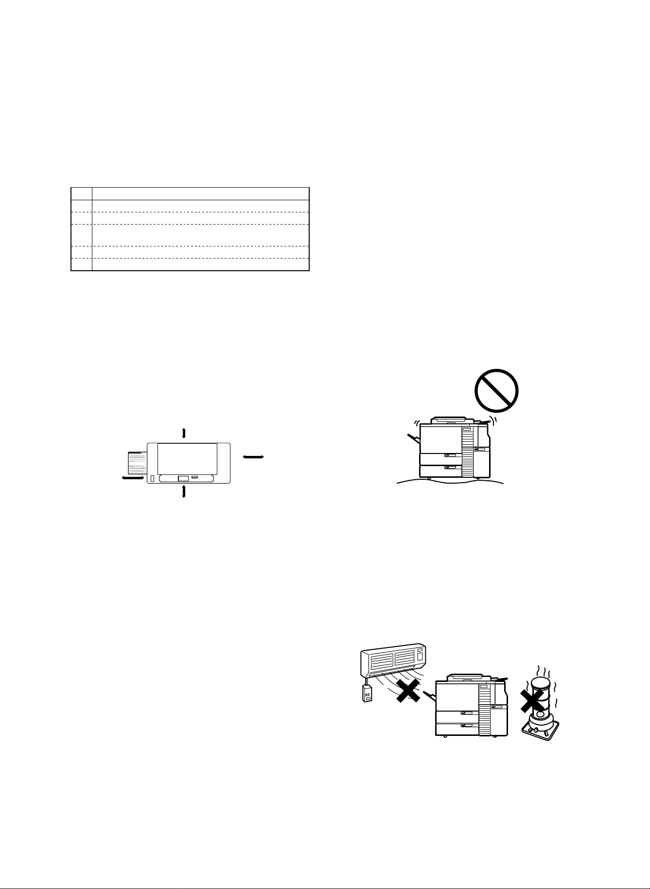
(1) Delivery space
Check the door sizes to allow delivery of the machine in advance.
(2) Installation space
Allow the following installation space around the machine for proper
operations and performances.
The space for options must be also considered.
Especially allow enough space at the back of the machine. If the back
space is insufficient, heat radiation and the dust proof function are
prevented, suppressing the machine performances and causing troubles.
30cm
60cm
80cm
120cm
(3) Power source (capacity, voltage, frequency,
safety, plug)
If the power source requirements are not satisfied, the machine cannot display full performances, and may cause dangerous troubles.
BE sure to follow the following instructions:
1) Power source capacity
Check that the power capacity is enough as specified below. If it is
insufficient, it must be corrected.
Current capacity (Japan 15A specification) 15 A or above
Japan 20A specification machine: 20 A or above
EX 100V series: 16 A or above
EX 200V series: 9 A or above
(4) Floor strength and level
The machine is heavy, and options add further weight. Be sure to
check the floor strength for safety.
If the machine is not leveled properly, the toner concentration control
is not performed properly, affecting copy quality adversely.
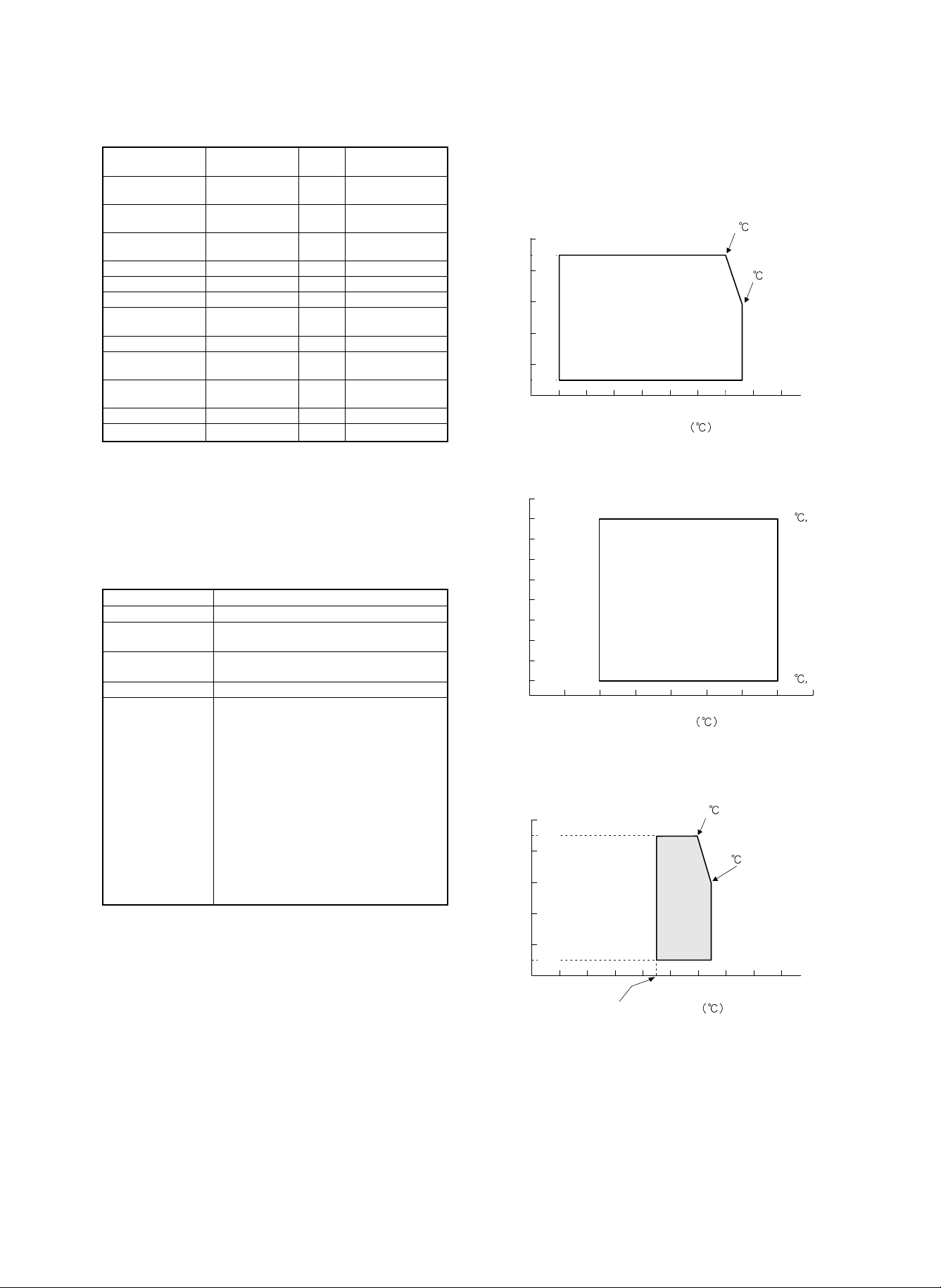
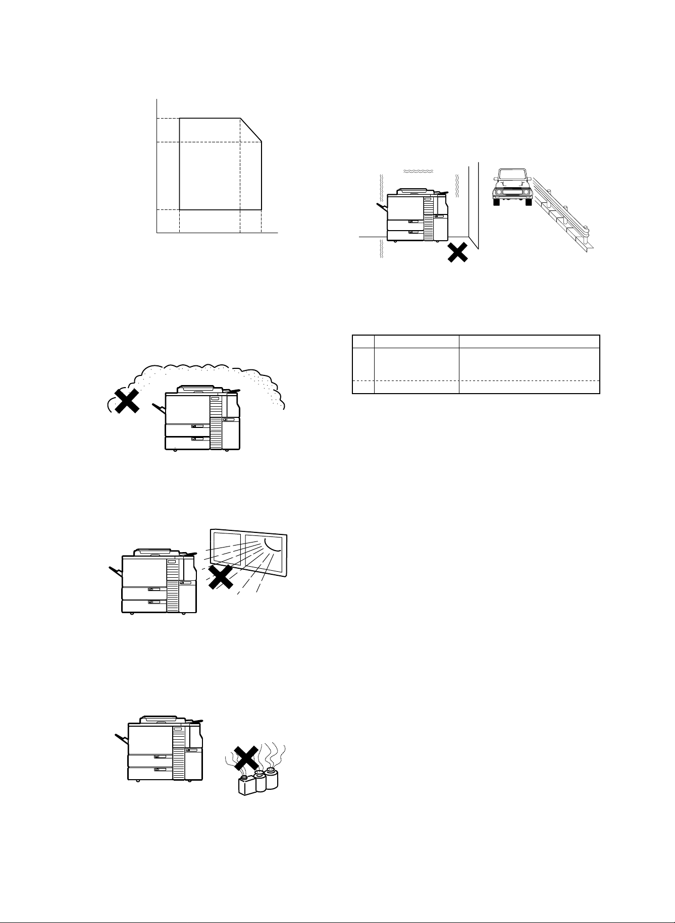
(5) Direct sunlight, dust, temperature, humidity,
gases, chemicals, vibrations
1) Temperature, humidity
The storage and operation of this copier is assured under the
following conditions. If the following conditions are exceeded, the
copier may not display full performances, causing troubles.
Especially when the humidity is too high, paper absorbs moisture
to cause paper jams and dirty copy.
4 – 3
Page 21
Humidity (RH)
85%
60%
20%
5) Vibrations
Do not install machines which produce vibrations around the cop-
ier. If vibrations are applied to the copier, copies may be blurred
and troubles may be caused.
15°C
Temperature (°C)
Do not install t he copie r near a he ater, a cooler, or a hum idifier. If
installed, the copier may form dew and cause troubles. Be careful
of ventilation, too.
2) Dust
If dust enters the copier, it may cause dirty copy, paper jams, and
short lifetime.
3) Direct sunlight
If the copier is exposed to direct sunlight, the external section may
be discolored, causing poor copy quality.
30°C 35°C
2. Transport and installation
No. Content Method
1 Facility, equipment,
man power
2 Delivery form Transported in packed conditions.
(1) Equipment, facility, man power
It is advisable to use a fork lift for efficiency and safety. If a fork lift is
not available, six men are required to move the machine. The copier
is very heavy. Consider for safety in delivery and installation work.
Transport of the copier must be made in the packed conditions to the
installing place (building).
(2) Delivery form
Remove the copier from the packing case outside the installing building, then carry it inside the building.
Use a fork lift.
(If a fork lift is not used, 6 men power
is required.)
4) Gases and chemicals
Do not install the copier near gases and chemicals. Especially be
careful of a diazo-type copier, which may produce ammonium
gas. The copy quality may be adversely affected, causing troubles.
4 – 4
Page 22
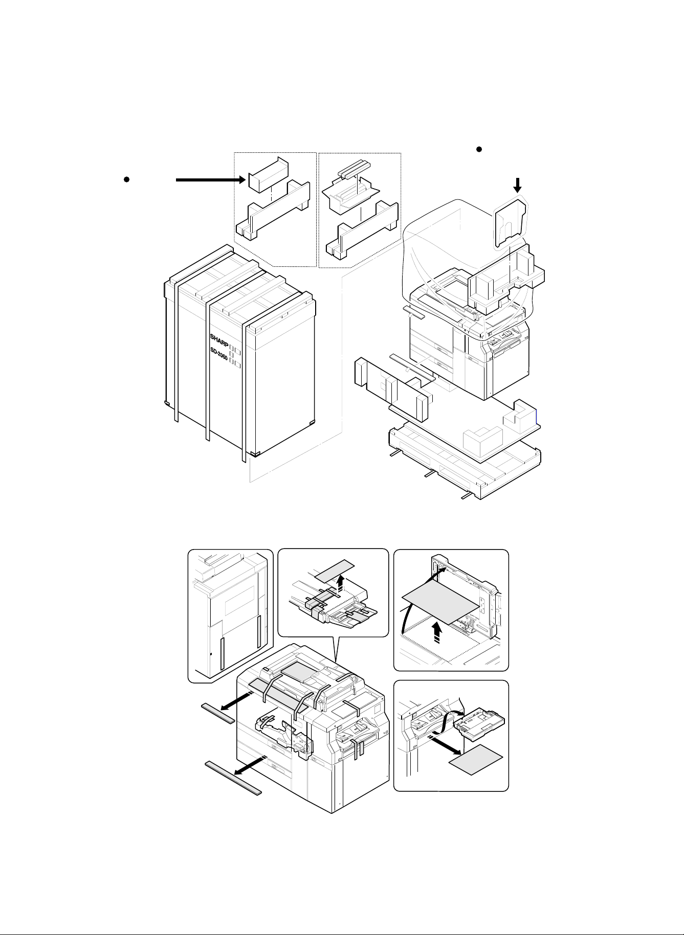
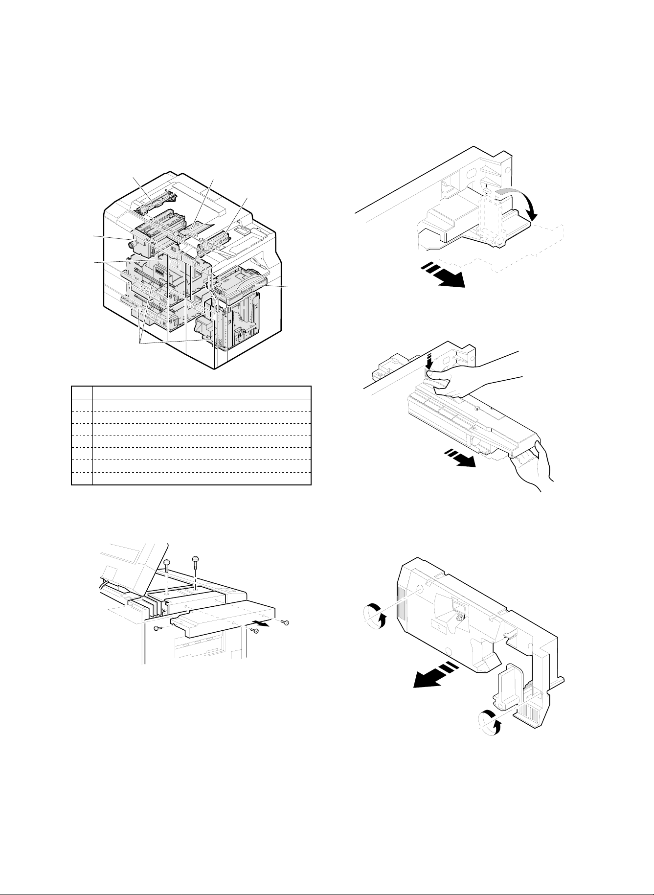
3. Unpacking
1) Remove the copier from the packing case as shown below:
Japan only
Upper cleaning roller unit
Lower cleaning roller unit
Oil application roller unit
Consumable parts unit
DNNT-6891FCZZ
Japan
Export
Japan only
Paper exit tray ass'y
LSOU-0054FCG4
2) Remove the fixing tapes and protection materials.
4 – 5
Page 23
4. Lock release
To prevent against dropping or damage of parts during transit, some
parts are locked.
Before use, those parts must be released.
Be sure to lock them again when transporting or moving the copier.
(2) No. 4/5 mirror unit lock release
1) Open the front cabinet and pull out the developing unit.
1
3
2
7
6
4
No. Content
1 Scanner unit
2 No. 4/5 mirror unit
3 Lens unit
4 Paper feed tray (No. 1, 2, 3)
5 Paper feed cassette
6 Photoconductor drum protection sheet (Except for Europe)
7 Paper exit guide (Fusing unit)
5
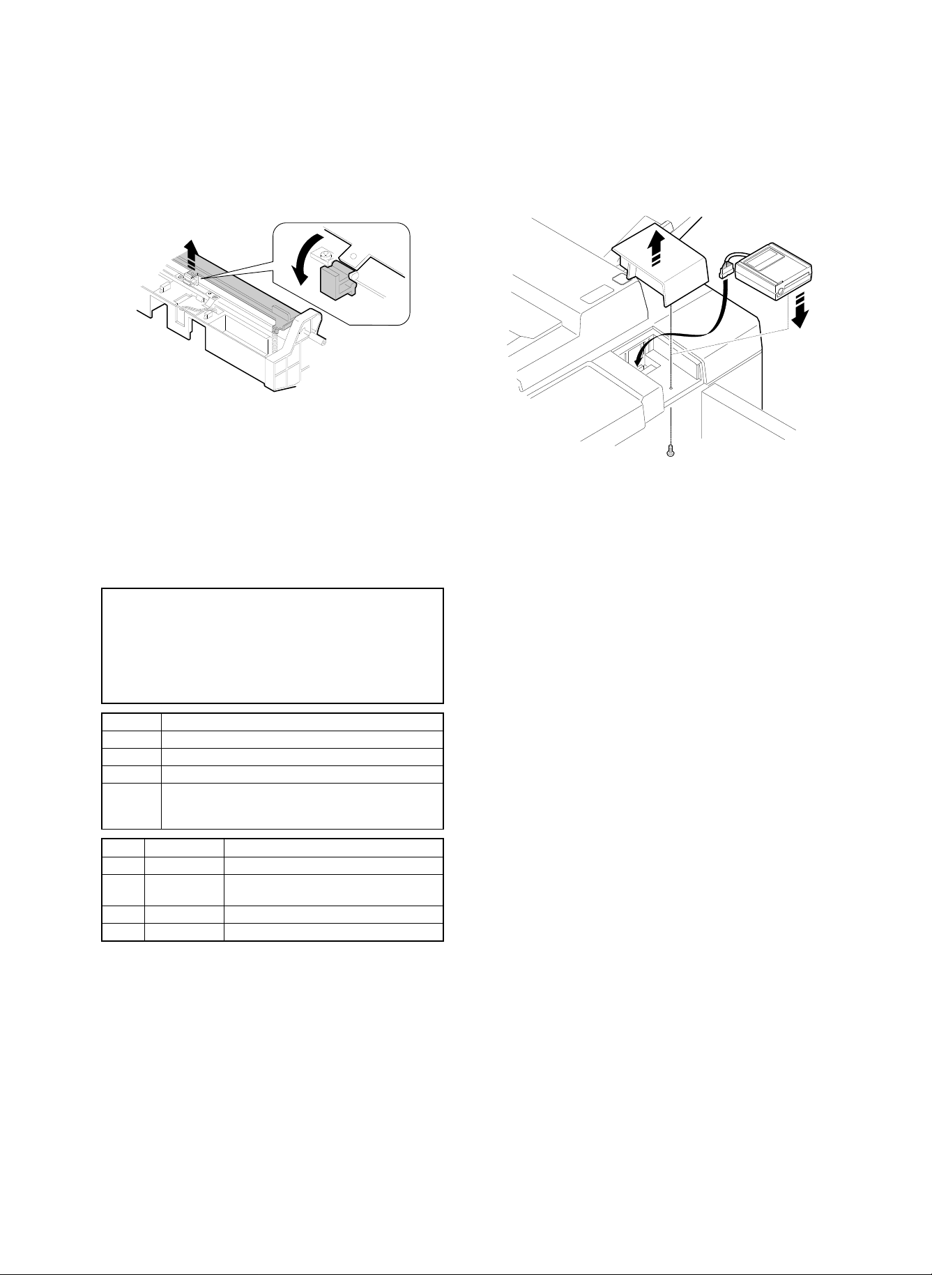
(1) Scanner unit lock release
Remove the cabinet, and remove the lock screw of the scanner unit.
(Locking method)
1) Manually move the scanner unit to the lock position and lock it
with the lock screw.
2) Pull out the process unit.
4 – 6
Page 24
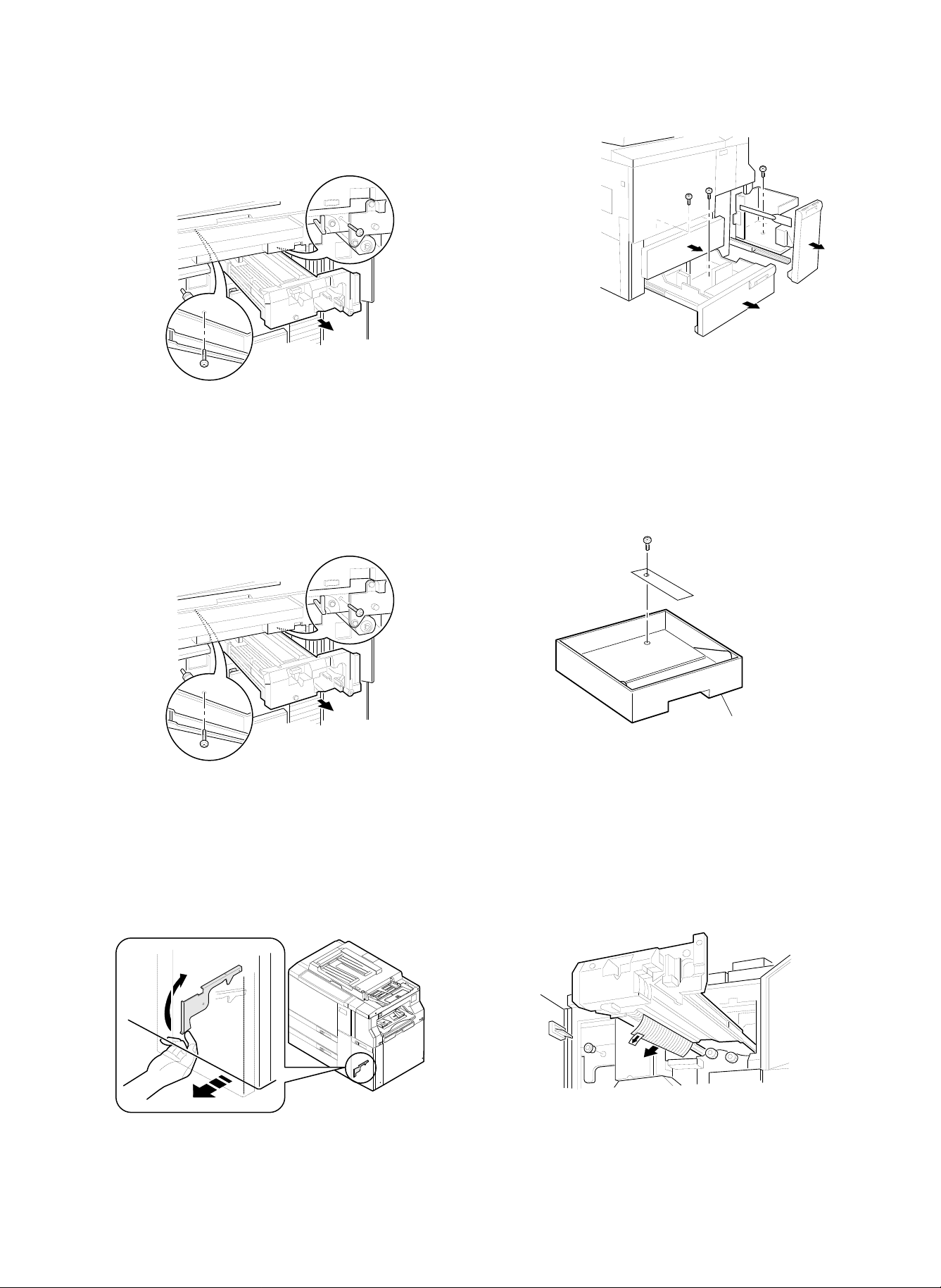
3) Remove the lock screw of No. 4/5 mirror unit.
(Locking method)
1) With the power ON, set the magnification ratio to normal. (The No.
4/5 mirror unit is fixed to the normal position.)
2) Turn off the power, and lock with the lock screw.
(3) Lens unit lock release
Remove the lock screw of the lens unit.
(Locking method)
1) Remove paper on the paper feed tray.
2) Turn on the power and wait until the paper feed tray falls to the
lowest position. (When the paper feed tray falls to the lowest
position, it stops.)
3) Turn off the power, pull out the paper feed tray, and lock it with the
lock screw.
(5) Paper feed cassette lock release
Remove the paper feed cassette lock screw.
(Locking method)
1) With the power ON, set the magnification ratio to normal. (The
lens unit is fixed to the normal position.)
2) Turn off the power, and lock with the lock screw.
(4) Paper feed tray lock release
Manually pull out No. 1, 2, and 3 paper feed trays, and remove the
lock screws.
Paper feed cassette
(6) Photoconductor drum protection sheet (Except
for Europe)
Remove the photoconductor drum protection sheet.
(Note) Do not remove white powder (starting powder) on the pho-
toconductor drum, which is to reduce friction between the
cleaning blade and the photoconductor drum.
If this powder is removed, friction between the cleaning blade
and the photoconductor drum is increased to reverse the
cleaning blade, damaging the photoconductor drum.
4 – 7
Page 25
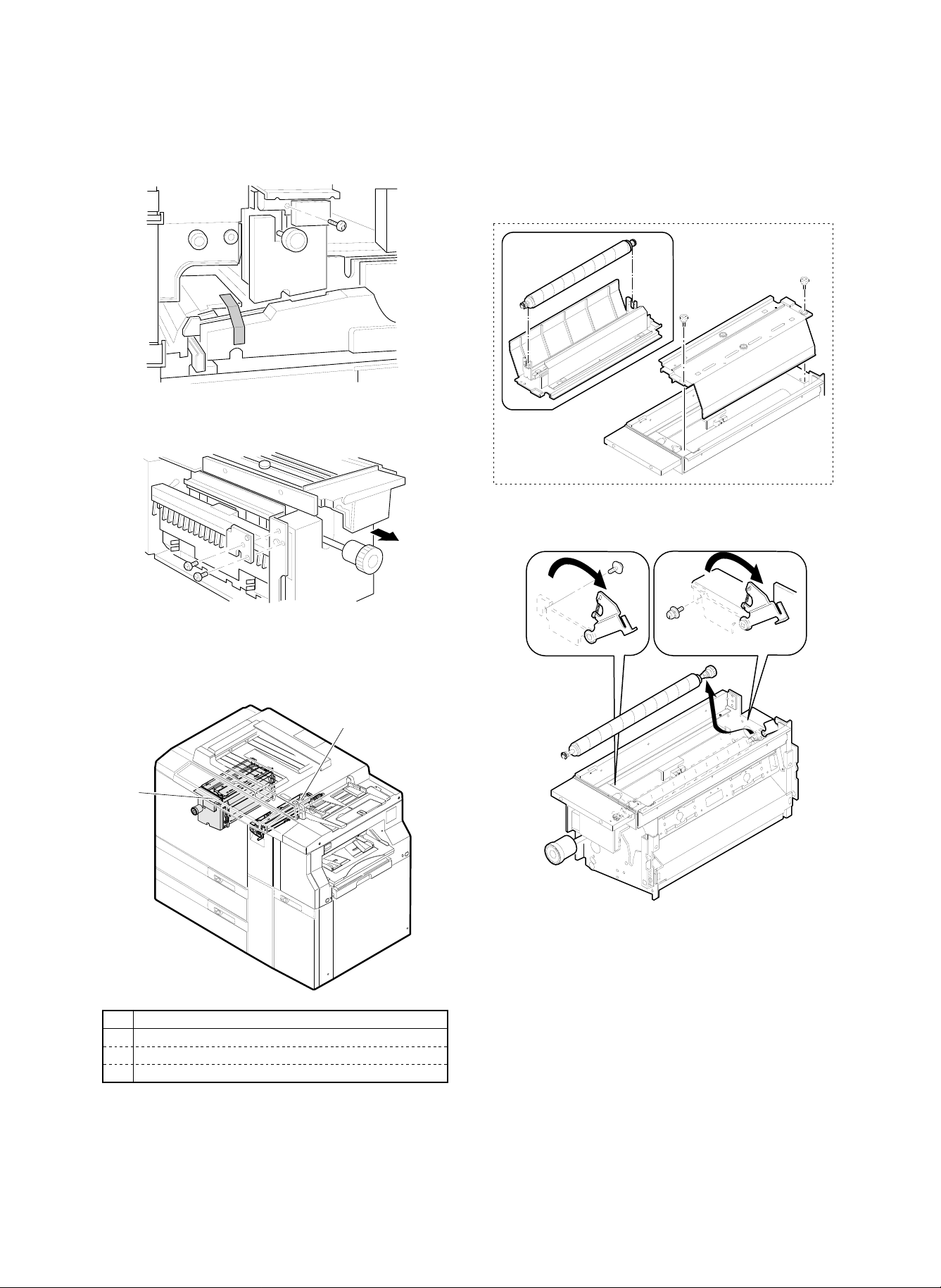
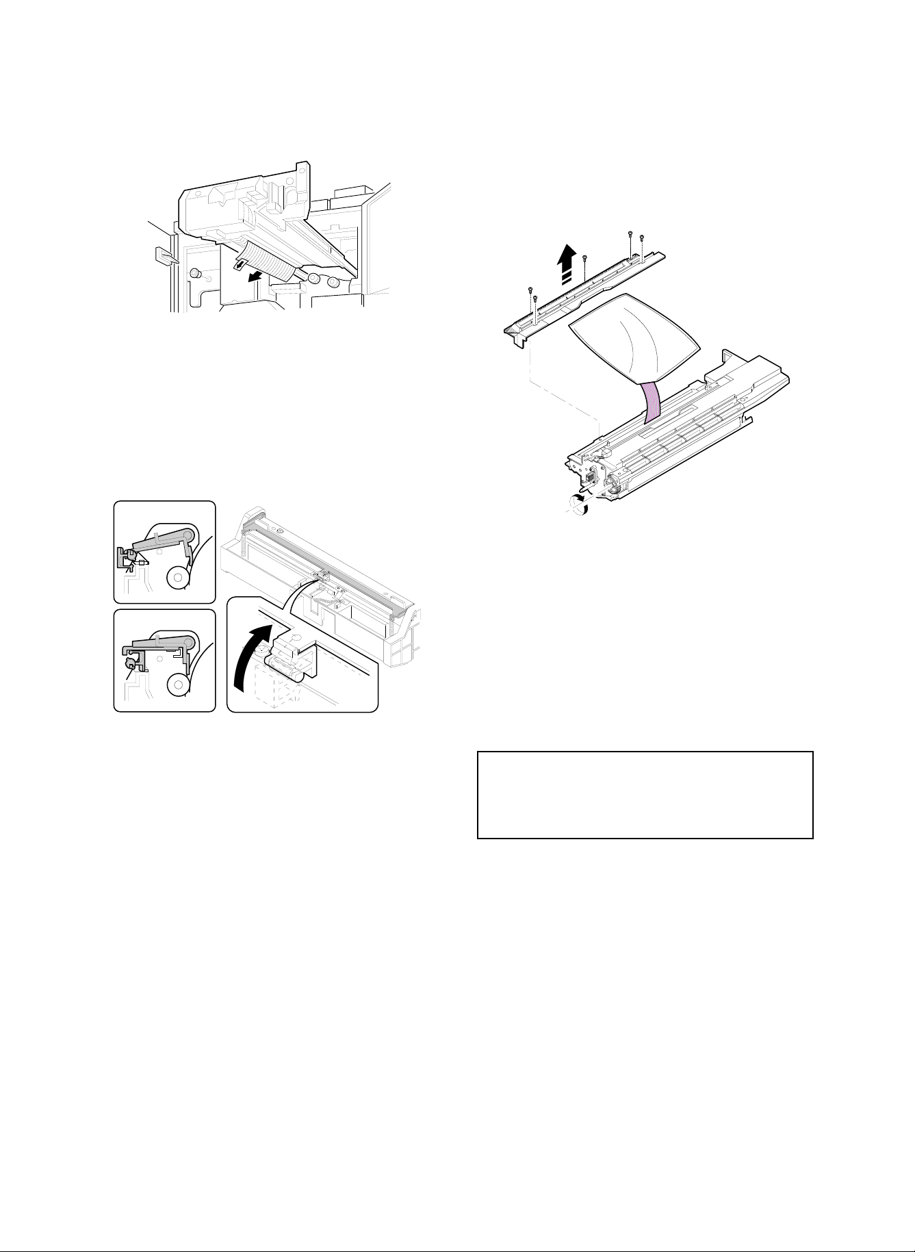
(7) Paper exit guide lock release (Fusing unit)
1) Pull out the fusing unit.
2) Remove the paper exit guide lock plate.
(1) Cleaning roller setup
1) Pull out the fusing unit.
2) Install two cleaning rollers for the upper fusing roller and install
one cleaning roller for the lower fusing roller.
(Japan only)
When installing, check that the tension spring applies
tension to the bearing of the cleaning roller.
5. Parts setup
1, 2
No. Content
1 Cleaning roller (2 pcs.) (Fusing unit)
2 Fusing roller pressure setup
3 Cleaning blade setup
3
4 – 8
Page 26
(Note) For installation of the fusing guide, put it in close contact with
the fusing guide positioning plate and secure it.
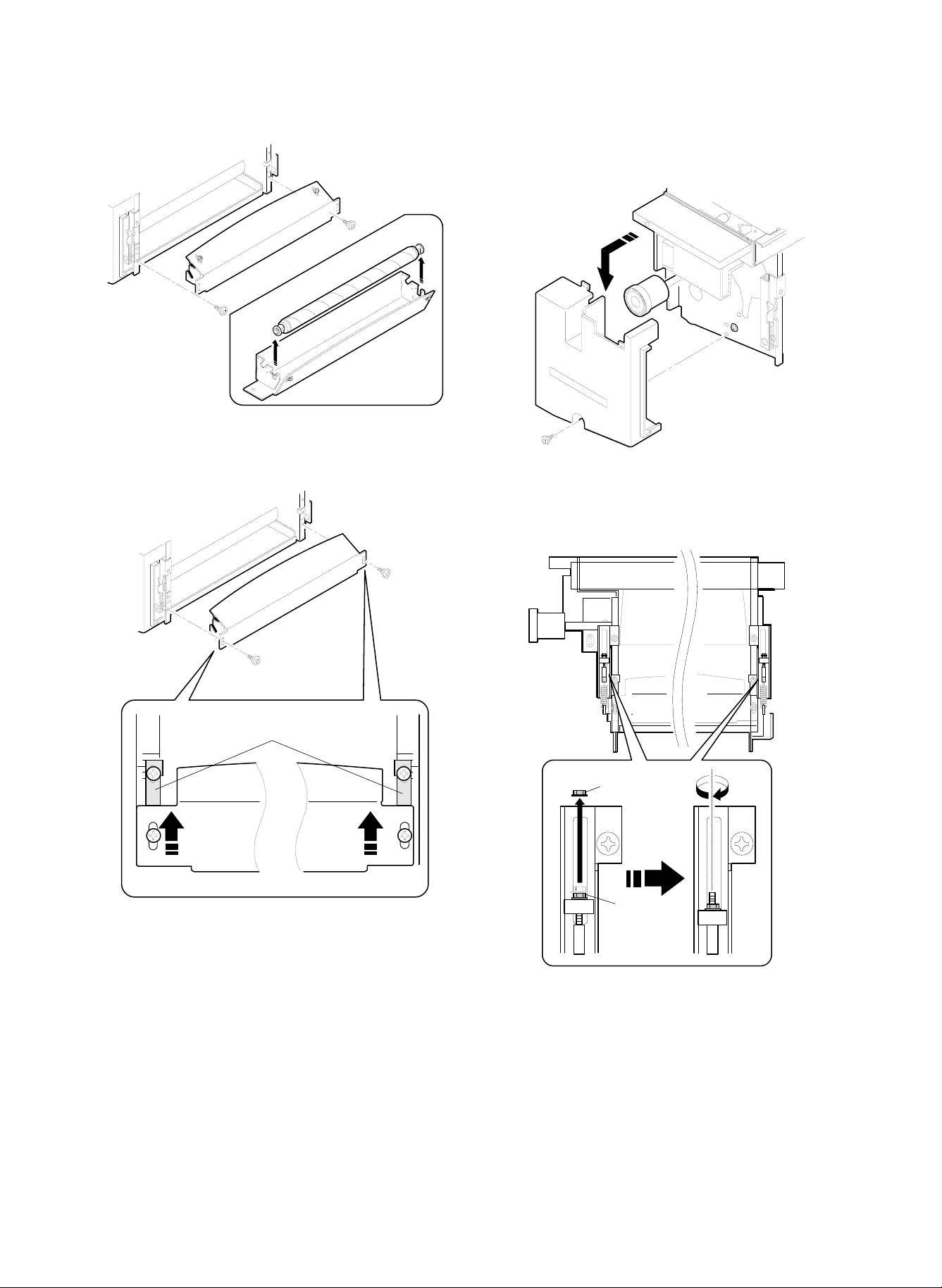
(2) Fusing roller pressure setup
1) Remove the fusing cover, and put down the pressure lever.
2) Remove the lock nut, and turn and fix the pressure adjustment nut
(blue) tightly.
(Tighten the nut until the collar clearance is eliminated.)
Positioning plate
Lock nut
Nut (Blue)
3) Install the lock nut.
4) Set the pressure lever and fix it.
4 – 9
Page 27
(3) Cleaning blade setup
1) Pull out the process unit and set the cleaning blade.
(Release the release block, and press the cleaning blade onto the
photoconductor drum surface.)
(Note) When the copier is not used for a long time, release the
cleaning blade pressure.
(3) Auditor (SF-EA11) installation
1) Remove the auditor installing section cover, and fix the auditor
(SF-EA11) with the screw.
6. Option installation
When an option is installed, option setting (registration) must be performed with SIM 26-1 and 26-3.
Also when an option is removed, option setting (registration) must be
canceled with SIM 26-1 and 26-3.
SIMULATION NO.26-1
SORTER/STAPLE SORTER SETTING?
0.NO SORTER
1.SF-S55
2.SF-S53/S16
3.SF-S55(DISABLE AUTO FRONT ACCESS
WHEN FEEDING FROM BYPASS-TRAY.)
Set value Content
0 Without sorter
1 With SF-S55 installed
2 With SF-S53 or SF-S16 installed
3 With SF-S55 installed (to inhibit automatic front
take-up of paper in manual paper feed [useful to load
thin films on the manual feed tray])
Code Name Content
1 P10 (500) Internal auditor mode (500 dept.)
P10 (3100) Internal auditor mode (500 dept.)
2
3 SF-EA11/12 Card counter mode (SF-EA11)
4 OTHER Others
+ expansion RAM mode (2600 dept.)
When using the auditor (SF-EA11), SIM 26-3 must be set for use of
the auditor (SF-EA11).
The external auditor (SF-EA11) and the internal auditor (in the main
control PWB) cannot be used together. Either of them must be selected with SIM 26-3.
(1) Sorter (SF-S55/53/16) installation
(2) Staple cartridge setup
For setup of a staple cartridge, refer to the Service Manual of each
model.
4 – 10
Page 28
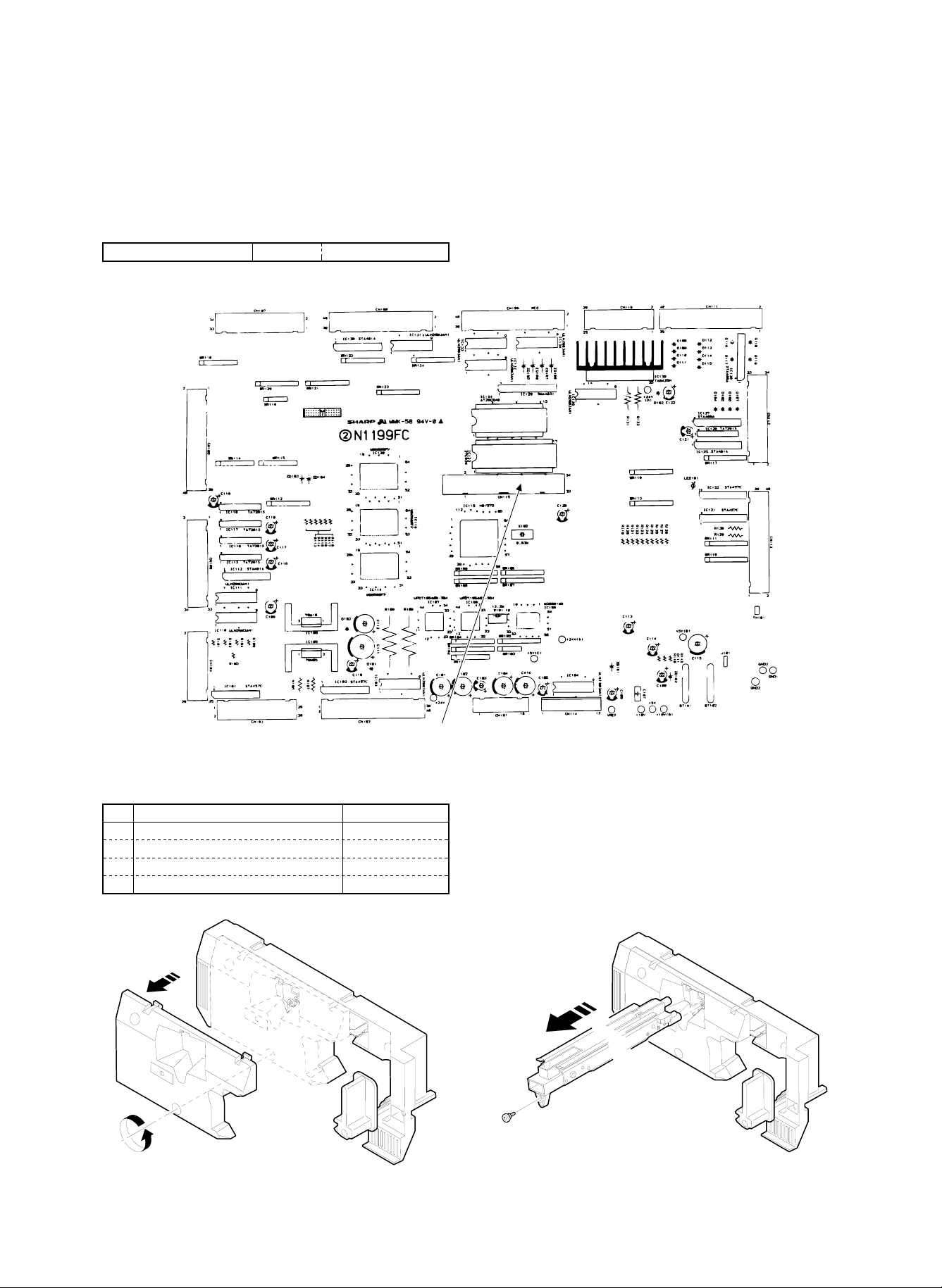
(4) Expansion memory for the internal auditor
The internal auditor (in the main control PWB) has the capacity of
controlling 500 departments. By adding expansion memory on the
main control PWB, additional 2,600 departments can be controlled, in
total 3,100 departments.
(Note) When an expansion memory is installed, it must be initialized
with SIM 26-3.
Expansion memory (with frame) PARTS CODE
1) Install an expansion memory on the main control PWB.
DKIT-0321FCZZ
Install the expansion memory to connector CN115.
7. Consumable parts setup
(When replacing the consumable parts, follow these procedures.)
No. Content Method
1 Photoconductor drum (Europe only)
2 Developer setup
3 Toner concentration control level setting Set with SIM 25-2.
4 Toner setup
(1) Photoconductor drum setup (Europe only)
Since, in Europe, the photoconductor is not installed to the copier
body, this procedure must be performed.
1) Pull out the process unit, and remove the main charger unit and
the process unit cover.
4 – 11
Page 29
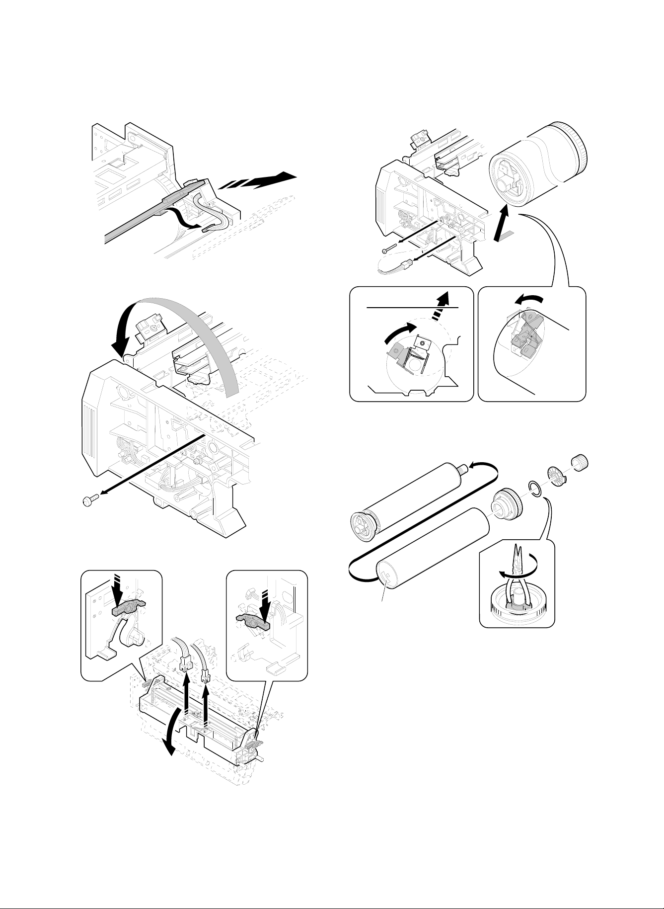
2) Remove the blank lamp unit and the cleaner unit, and open the
main charger holder.
3) Remove the photoconductor drum shaft and the flange unit.
4) Record the serial No. inside the photoconductor drum.
Label
5) Install the photoconductor drum to the flange unit.
(Do not remove the protection sheet.)
6) Install the photoconductor drum to the process unit.
7) Replace the parts to the process unit.
4 – 12
Page 30
8) Remove the photoconductor drum protection sheet.
(Note) Do not remove white powder (starting powder) on the pho-
toconductor drum, which is to reduce friction between the
cleaning blade and the photoconductor drum.
If this powder is removed, friction between the cleaning blade
and the photoconductor drum is increased to reverse the
cleaning blade, damaging the photoconductor drum.
9) Set the cleaning blade.
(Release the release block, and press the cleaning blade onto the
photoconductor drum surface.)
(2) Developer setup
1) Remove the developing unit cover, and pour developer into the
developing unit.
Manually turn the developing roller drive gear, and supply two
packs of developer (1kg × 2).
(Note) When the copier is not used for a long time, release the
cleaning blade pressure.
(Note) Developer for the SD-2060 cannot be used for the SD-2260.
(3) Toner concentration control level setting
Virgin developer has been adjusted to the specified toner concentration. This density is detected by the sensor and stored. After that, the
toner concentration level is used as the reference level, and developer is controlled to provide the level same as the virgin developer.
The above operation is performed with SIM 25-2.
When developer is replaced, this procedure must be performed.
1) With the front cabinet open (with the front cabinet open/close
detection switch OFF), turn on the power to enter the SIM 25-2
mode.
SIMULATION NO. 25
INPUT 1 ∼ 2
1. Toner concentration SENSOR MONITOR
2. AUTO DV DENSITY
(Note) Do not turn on the power with the front cabinet closed (with
the front cabinet open/close detection switch ON). Toner
would be supplied to the developing unit and the toner concentration of the virgin developer may not be the reference
level.
2) Close the front cabinet. (The front cabinet open/close detection
switch is turned ON.)
3) Press the START button.
Developer is stirred for 3 minutes, and the reference toner con-
centration level is memorized.
Be sure not to cancel SIM 25-2 until stirring of developer is com-
pleted in 3 minutes.
If EU trouble or EL trouble occurs midway, check for abnormality
in the developing unit.
4 – 13
Page 31
(Note) In case of memory trouble, if the main control PWB is re-
placed, the stored reference toner concentration level is
cleared.
For countermeasures against this, there are two ways as
shown below. Use one of them according to the situation.
* When the toner concentration level is normal (presump-
tion):
(Countermeasure) Execute SIM 25-2 to set the reference
toner concentration again.
* When the toner concentration is not normal:
Replace the developer with new one, and execute SIM252 to set the reference toner concentration level.
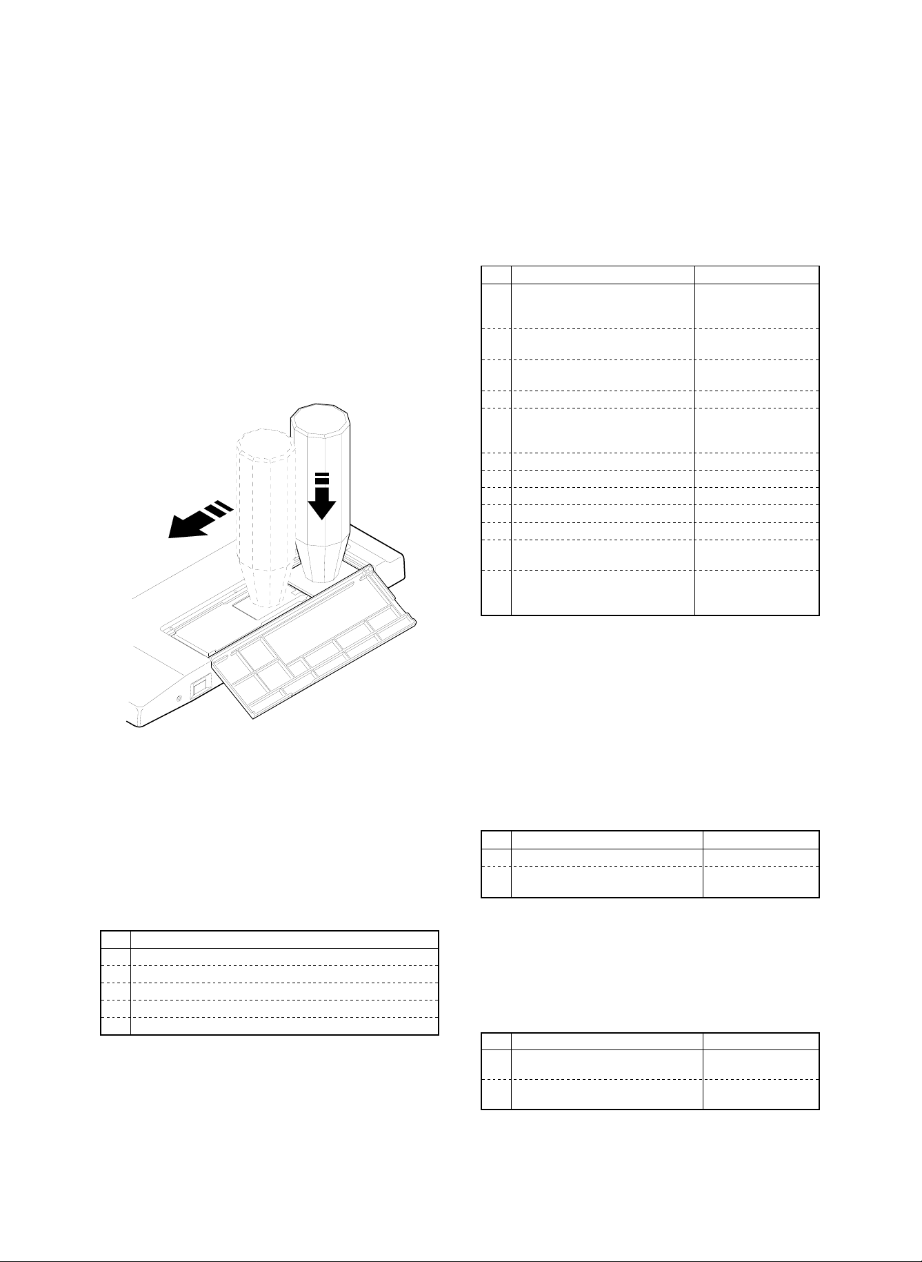
(4) Toner setup
Fit the toner bottle to the toner supply port, and slide it.
Confirm that all toner falls, and remove the toner bottle from the toner
supply port.
5) Others (cabinet, etc.)
9. Operational specification setup
The operational specifications of the copier must be set according to
the user’s necessity.
For setting with software, refer to the sections shown in the table
below.
No. Content Method
1 Separation charger voltage setting
(according to the altitude)
2 No. 1 paper feed tray paper size
setting (hardware)
3 No. 1 paper feed tray paper size
setting (software)
4 Option setting (Software) Set with SIM 26-1.
5 Expansion memory initializing (only
when an expansion memory is
installed)
6 Auditor operation mode setting Set with SIM 26-3.
7 Count mode setting Set with SIM 26-5.
8 Destination specification setting Set with SIM 26-6.
9 Maintenance cycle setting Set with SIM 21-1.
10 Toner save mode YES/NO setting Set with SIM 26-18.
11 Power shut off operation mode
setting
12 Display language setting Replace the data ROM
Check the high voltage
PWB connector CN2
connection.
Refer to [6]-2-C.
Set with SIM 26-2.
Set with SIM 26-3.
Set with SIM 26-26.
on the operation
control PWB.
(Note) Do not supply two or more bottles at one time. If two or more
toner is supplied at one time, toner jam may occur in the
toner hopper. Supply toner only when "SUPPLY TONER" display is made on the LCD.
8. Cleaning
Clean the following units.
For copiers which have been stored for a long time, some sections
other than the following units may be dirtied. Clean them according to
necessity.
No. Content
1 Main charger unit
2 Pre-transfer charger unit
3 Transfer/separation charger unit
4 Original table glass
Others (cabinet, etc.)
1) Main charger unit (screen grid, saw teeth section)
2) Pre-transfer charger unit (charger wire)
3) Transfer/separation charger unit (charger wire)
4) Original table glass
10. Image correction function setup and
check
Image correction function is set up when shipping. Check it before
use.
For correct performance of image correction (main charger, copy
lamp, copy density control correction), the operational setting of
image correction must be made.
The operational setting of image correction is made with simulations.
For the setting procedure, refer to the sections listed in the table
below.
No. Content Method
1 Image correction function setting Set SIM 44-1 to 127.
2 Main charger correction reference
density setting
Set SIM 44-4 to 75.
1 1. Image density sensor, photoconductor
drum mark sensor operation check
These sensors are to control image correction, and must be adjusted
to the proper sensitivity.
They are adjusted when shipping. Check it before use.
No. Content Method
1 Photoconductor drum mark sensor
sensitivity check (adjustment)
2 Image density sensor sensitivity
check (adjustment)
Check with SIM 44-2.
(adjustment)
Check with SIM 44-3.
(adjustment)
4 – 14
Page 32

12. Image correction execution
13. Copy density check
When the power is supplied, warming up is started. During warm up,
the following corrections are performed to adjust the copy density
automatically.
1) Main charger grid voltage correction
2) Optical dirt correction (copy lamp voltage)
3) Auto copy density adjustment (copy lamp voltage)
Copy density adjustment reference
Copy mode
(1) Non-toner save
mode
(2) Toner save mode
(Set by key operator
program P20)
a Manual copy mode copy density
adjustment
b Photo copy mode copy density
adjustment
c Auto copy mode copy density adjustment 3 4 3 2
a Manual copy mode copy density
adjustment
c Auto copy mode copy density adjustment 3 4 3 2
Make a copy in each copy mode, and check that the copy density is
within the level in the table below.
Before checking the copy density, be sure to check that the key
operator program 20 copy density level is set to 3.
Selection between the toner save mode and the non-toner-save
mode is made with the key operator pr o gr a m 22 .
(Test chart compatibility table)
1 10
23456789
UKOG-0162FCZZ
Density No.
UKOG-0089CSZZ
Density No.
KODAK
gray scale
Operation panel
density setting
13765
531 W
13765
531 W
13765
531 W
12345678910W
0.1 0.2 0.3 0.5 1.9 0
123419A
Density level UKOG-0162FCZZ gray scale
Key operator
P20 setting
Copied
Slightly
copied
W
Not
copied
14. Focus (resolution), copy magnification
ratio check (adjustment)
Make a copy in each copy mode, and check that the focus (resolution) and the copy magnification ratio are in the range shown in table
below.
For the adjustment and checking procedures, refer to the sections
shown in the table.
Copy magnification ratio Copy center Corners
100% 5.0 lines/mm 4.5 lines/mm
101 ∼ 200% 5.0 lines/mm 4.5 lines/mm
90 ∼ 99% 4.5 lines/mm 4.0 lines/mm
64 ∼ 89% 3.6 lines/mm 3.2 lines/mm
50 ∼ 63% 3.2 lines/mm 2.8 lines/mm
No. Content Method
1 Focus (resolution)
(Normal, 50%, 200%)
2 Vertical copy magnification ration
(normal, 50%, 200%)
3 Horizontal copy magnification ration
(normal)
Adjust with SIM 48-1
(A/B/C).
Adjust with SIM 48-1
(D/E/F).
Adjust with SIM 48-1.
4 – 15
Page 33

15. Operation check
Make a copy in each copy mode listed below, and check that the
operation is normal.
No. Content
1 Paper size detection (manual paper feed tray)
2 Paper size detection (No. 2, 3 paper feed tray)
3 Original size detection (Original table)
4 Original size detection (RADF original feed tray)
5 (Manual paper feed tray, No. 1, 2, 3 paper feed tray,
cassette) copying
6 RADF copying (S-S mode)
7 RADF copying (S-D mode)
8 RADF copying (D-D mode)
9 RADF copying (D-S mode)
10 Zoom copying (enlargement, reduction)
11 Sort mode copying (with SF-S16/53/55 installed)
12 Group mode copying (with SF-S16/53/55 installed)
13 Sort staple mode copy (with SF-S16/53/55 installed)
16. Copy image center shift check
Make a copy in each copy mode listed below, and check that the
copy image center shift is within the allowable range.
For the adjustment and checking procedures, refer to the sections
shown in the table.
Original table mode Single ±2.0 mm
Duplex ±2.0 mm
Overall (RADF) mode Single S → S ±3.0 mm
D → S ±4.0 mm
Duplex S → D ±3.0 mm
D → D ±4.0 mm
No. Content Method
1 Original table copy mode
(front) (Manual paper feed
tray, No. 1, 2, 3 paper fe ed
tray, paper feed cassette)
2 Original table copy mode
(back) (No. 1, 2, 3 paper
feed tray, paper feed
cassette)
3 RADF copy mode Adjust by changing the
Adjust by changing the
positions of the paper feed
tray, the paper feed cassette,
and the manual paper feed
tray.
Adjust by changing the
position of the duplex tray.
position of the RADF paper
feed tray.
No. Content Method
1 Original table copy mode (lead
edge image loss, void area) (rear
edge void area)
2 RADF copy mode (S-S mode)
(lead edge image loss, void area)
3 RADF copy mode (D-D mode)
(lead edge image loss, void area,
rear edge void area)
4 RADF thin film copy mode (lead
edge image loss, void area, rear
edge void area)
5 RADF stepping copy mode (lead
edge image loss, void area, rear
edge void area)
Adjust with SIM 50-1.
In the RADF copy mode,
the adjustment value of
SIM 53-1 must be also
checked.
18. Recording of adjustment/setting
values, ROM version
It is advisable to record the adjustment and setting values as well as
the ROM version. If they are not recorded, all the adjustments must
be executed again from the beginning when a memory trouble occurs, or when the main control PWB is replaced, or memory on the
main control PWB is replaced.
If, however, the adjustment values are recorded, it is only required to
enter the values with the corresponding simulations. This greatly increases the efficiency in servicing.
By use of the commander (SF-EA13), all the adjustment and setting
values and the ROM version are printed.
If the commander (SF-EA13) is not available, execute each simulation related to each adjustment and setting, and read the adjustment
and setting values and record them.
For the concrete procedures, refer to the sections listed in the table
below.
19. Explana tio n fo r use r oper ations
20. Others
(1) Fixing adjuster setup
Turn the adjuster to fix the copier.
17. Image loss, void area check
(adjustment)
Make a copy in each copy mode listed below, and check that the
image loss and void area are within the allowable range.
For the adjustment and checking procedures, refer to the sections
shown in the table.
Item Lead edge Rear edge
Image loss 1.0 ∼ 4.5 mm —
Voide area 1.0 ∼ 3.0 mm 1.0 ∼ 4.0 mm
Image shift for the paper 0±1.5 mm —
4 – 16
Lock
Adjuster
Release
Page 34

[5] EXTERNAL VIEWS AND INTERNAL STRUCTURE
1. External views
1 2 3 4 5 6 7
8109
11
12
13
14
15
16
17
18
Copy tray
1
Document exit section cover
4
Document table
7
Document guide
F
Power switch
I
Manual feed guide tray
L
Front cover
O
Tray falling button/lamp
R
19
2120 22 23
Clip tray
2
Document exit section
5
Document feed lamp, document
8
remaining lamp
Document set table
G
Manual paper feed guide
J
Heater switch
M
No. 3 paper feed tray
P
No. 1 paper feed tray
S
5 – 1
Operation panel
3
Reversing automatic document feeder
6
(RADF) unit
Paper feed pressure release button
9
Toner box cover
H
Manual paper feed tray
K
Paper cassette
N
No. 2 paper feed tray
Q
Page 35

2. Internal operation parts
27262524
28 29 3130
Operation Manual storing section
T
OPC drum
W
Duplex unit
Z
Roller rotating knob
U
Toner collection container storing
X
section cover
Transport section open/close lever
[
Fusing section lock lever
V
Left side cover
Y
5 – 2
Page 36

18
17
16
INSERTS
TRANSPARENCY
COVERS/INSERTS
DUAL PAGE COPY
11 12 13 14 15
SPECIAL MODES
COPIES MADE
COPIES SELECTED
SCROLL DISPLAY
MARGIN SHIFT
PROGRAM
INFORMATION
3
2
1
P
ERASE
START
6
5
4
CA
CLEAR ALL
CHANGE
9
CLEAR/STOP
8
7
INTERRUPT
TRAY SELECT
282625242322
27
C/
AUDIT
CLEAR
0/
Sort/group key/display lamp
Reduction/normal/enlargement key
Operation guide key/display lamp
COPIES SELECTED display
Binding margin key/display lamp
OHP insert paper insert key/display lamp
Message screen
10-key pad
3
6
9
H
K
N
Q
T
Start key/start lamp
W
31
2 4 5 6 7 8 9 10
AUTO IMAGE
1
ORIGINAL TO COPY
SORT
SORTER
21
Staple sort key/display lamp
Magnification ratio auto select key
Message forward scroll key
All clear key
Frame erase/display lamp
Cover/index paper insert key/display lamp
Copy exposure key
Interruption key/display lamp
Clear/stop key
2
5
8
G
J
M
P
S
V
DARK
AUTO
MANUAL
ZOOM
REDUCTION ENLARGEMENT
2
221
1
1
1
EVEN NUMBER
ODD NUMBER
(ORIGINALS)
GROUP
STAPLE
SORT
PHOTO
EXPOSURE
LIGHT
1
2
PRE-COUNT
ORIGINALS
CHANGE
20
19
LCD brightness adjusting dial
Document → Copy selection/display lamp
Zoom key
Program key
COPIES MADE display
1-set 2-copy key/display lamp
Setting change key (Staple sorter SF-S55)
Tray selection key
Zero/department count end key
Setting change key
3. Operation panel
5 – 3
1
4
7
F
I
L
O
R
U
X
Page 37

4. Internal parts
K1
I14
I12
I13
H8
M1
L5
L6 L10
J2
J1
J2
L4L9
I9
H5
L7 L9
D5
E2
H7 H6
D6
D7
D2
H4
H2
L8 L3
G2C8D4D1E1C9C3C2C1C4C11C5C12I8I7C10I1I5
G1 B5
H1
G3
L1
L2
C6
F2
F1C7
B3
A2
A1
A3
A5
A4
A6
A8
A13
A7
B4
B4
B4
B2
A9
A10
A16
B4
A15
A16
I4I2
I6
I10I3
I11
B1
E3D3A14
H3A12 A11
No. Section No. Part name Remark
A Paper feed section 1 Manual paper feed pick-up roller
2 Manual paper feed roller
3 Manual paper feed separation roller
4 Cassette pick-up roller
5 Cassette paper feed roller
6 Cassette separation roller
7 Blower unit (No. 1 paper feed tray)
8 Suction unit (No. 1 paper feed tray)
9 Blower unit (No. 2 paper feed tray)
10 Suction unit (No. 2 paper feed tray)
11 Blower unit (No. 3 paper feed unit)
12 Suction unit (No. 3 paper feed unit)
13 Paper feed belt (No. 1 paper feed tray)
14 Paper feed belt (No. 2 paper feed tray)
15 Paper feed belt (No. 3 paper feed tray)
16 Lift wire
B Paper transport section 1 Transport suction belt
2 Transport roller 1 (with clutch)
3 Transport roller 2 (with clutch)
4 Transport roller
5 Resist roller
5 – 4
Page 38

No. Section No. Part name Remark
C Optical section 1 No. 1 mirror
2 Copy lamp
3 Reflect
4 No. 2 mirror
5 No. 3 mirror
6 Mo. 4 mirror
7 No. 5 mirror
8 No. 6 mirror
9 Lens
10 Scanner drive wire
11 Document table (glass)
12 Document stopper
D Image forming section 1 Main charger unit
2 Pre-transfer discharging charger unit
3 Transfer/separation charger unit
4 Blank lamp unit
5 Discharge lamp unit
6 OPC drum
7 OPC drum heater
E Cleaner section 1 Cleaning blade
2 Cleaning brush
3 Waste toner transport screw
F Toner hopper section 1 Toner transport bar
2 Toner supply roller
G Developing section 1 Developing roller
2 Toner stirring roller
3 Toner transport roller
H Duplex section 1 Blower unit
2 Suction unit
3 Paper feed belt
4 Paper stopper
5 Drive belt
6 Alignment plate (width)
7 Alignment plate (transport direction)
8 Transport roller
I Fusing section 1 Heat roller
2 Pressure roller
3 Sub heater lamp
4 Main heater lamp
5 operation pawl (Upper)
6 Separation pawl (Lower)
7 Cleaning roller (Upper)
8 Auxiliary cleaning roller (Upper)
(Japan only)
9 Cleaning felt
10 Paper dust cleaning roller
11 Paper dust cleaning roller (lower)
12 Duplex gate
13 Curl correction belt
14 Paper exit roller
J Switchback section 1 Switchback gate
2 Transport roller
K Paper exit section 1 Paper exit roller
L RADF 1 RADF pick-up roller
2 RADF paper feed roller
3 RADF separation roller
4 Transport roller
5 Paper exit/reverse roller
6 Reverse gate
7 Tension roller
8 Resist roller
9 Transport roller
10 Paper exit roller
M Others 1 Waste toner bottle
5 – 5
Page 39

5. Sensors and detectors
TFD
DPPD
DSBD
DTBHPS
TUD2
TLD2
DDSW
POD2
TGOD
RDD
MHP
DEMRS
POD1
FUSUSSW
HLTS
THS
LHP
ILSW
DTPD
CLTS
AUOD
PCS
AES
PSD
DTWHPS
DTMRS1
AEDS
DMS
DTMRS2
PPD3
DSW
DTS
DWS
DFMHPS
DRS
TNCS
DSD
TES1
DFMRS
MBHP
DWD
MPFD
DLS1
TES2
DLS2
TNCTR
CPFD
MSW
MDOP
MPED
CLUD
CPED
PWS
MPSD2
MPSD1
MTOP
CSD
TUD1/
TPED1
CSS
TLMD1
DRSW
TSW1
PPD2
PFD1
TBBOX
TNF
Code
(Signal name)
TUD3
TPTD2
TPTD3
TLD3
DPID
TSW2
TSW3
PS21~26
PS31~36
TLMD2
TLMD3
Name Type Function, operation
PFD3
PFD2
PPD1 TLD1
AEDS Optical dirt sensor Photo diode Optical section dirt detection
AES AE sensor Photo diode Document density detection
CLTS Thermostat ((Optical section) Thermostat Optical section overheat protection (Copy lamp AC power line is cut off.)
CLUD Paper cassette paper top detector Photo transmission Paper cassette lift plate upper limit position detection
CPED Paper cassette paper empty detector Photo transmission Paper cassette paper empty detection
CPFD Paper feed detector (Paper cassette) Photo transmission Detection of paper fed from the paper cassette
CSD Paper cassette detector Photo transmission Detection of paper cassette installed
CSS Cassette size sensor (5 lead switches) Lead switch Detection of paper size on the paper cassette
DDSW Open/close detection switches (switchback cabinet
section) 2 pcs.
Microswitch When the switchback section cabinet is opened, the switchback DC24V
power line is opened.
Switchback section cabinet open/close is detected.
5 – 6
DPFD
TPTD1
Page 40

Code
(Signal name)
DFMHPS Blower valve home position sensor (Duplex) Photo transmission Blower valve home position (Duplex) detection
DRSW Drum heater switch See-saw switch De-moisture heater switch
DMS OPC drum mark sensor Photo transistor OPC drum marking detection
DPFD Paper feed detector (Duplex) Photo transmission Detection of paper fed from the duplex tray
DPID Paper entry detector 2 (Duplex) Photo transmission Detection of paper entry into the duplex tray
DPPD Paper entry detector 1 (Duplex) Photo transmission Detection of paper entry into the duplex section
DSBD Paper entry detector (Switchback) Photo transmission Paper entry detection in the switchback section
DSW Open/close detection switch (Front cabinet
section) 2 pcs.
DTBHPS Alignment plate (length) home position sensor Photo transmission Alignment plate (length) home position sensor
DTPD Paper sensor (Duplex) Photo transmission Duplex tray paper detection
DTWHPS Alignment plate (width) home position sensor Photo transmission Alignment plate (width) home position sensor
FUSUS SW Safety switch (Fusing section) Microswitch Cuts the heater lamp power line simultaneously when the fusing unit release
HLTS Thermostat (Fusing section) Thermostat Fusing section overheat protection (The heater lamp AC power line is cut off.)
ILSW Fusing interlock switch Mechanical switch When the fusing unit is pulled out, the heater lamp power line is opened.
LHP Lens home position sensor Photo transmission Lens home position detection
MBHP Mirror base home position sensor Photo transmission No. 4/5 mirror unit home position sensor
MDOP Manual paper feed tray open/close sensor Lead switch Manual per feed tray open/close detection
MHP Scanner home position sensor Photo transmission Scanner unit home position sensor
MPED Paper emp ty de te ct or (Ma nu al pap er feed se cti o n) Photo transmission Manual paper feed section paper detection
MPFD Paper feed detector (Manual paper feed) Photo transmission Detection of paper fed from the manual paper feed section
MPSD1 Paper len gt h de tec to r 1 (Man ua l pape r fe ed se ctio n) Photo transmission Paper length detection (manual paper feed section)
MPSD2 Paper len gt h de tec to r 2 (Man ua l pape r fe ed se ctio n) Photo transmission Paper length detection (manual paper feed section)
MSW Main switch See-saw switch Main power ON/OFF (The power switch is forcibly turned off after the power
MTOP Manual paper feed tray pull-out detector Lead switch Manual paper feed tray pull-out detection
PFD1 Paper feed detector 1 Photo transmission Detection of paper fed from No. 1 paper feed tray
PFD2 Paper feed detector 2 Photo transmission Detection of paper fed from No. 2 paper feed tray
PFD3 Paper feed detector 3 Photo transmission Detection of paper fed from No. 3 paper feed tray
POD1 Paper exit detector 1 Photo transmission Detection of paper exit from the fusing section
POD2 Paper exit detector 2 Photo transmission Detection of paper exit from the fusing section
PPD1 Paper pass detector 1 Photo transmission Detection of paper pass from No. 3 paper feed tray
PPD2 Paper pass detector 2 Photo transmission Detection of paper pass in front of the resist roller
PPD3 Paper pass detector 3 Photo transmission Used as the operation timing signal for the transport roller and the resist roller.
PS21-26 Paper feed tray paper size detector (No. 2 tray) Lead switch Paper size detection
PS31-36 Paper feed tray paper size detector (No. 3 tray) Lead switch Paper size detection
PCS Image density sensor Photo transistor Detection of toner patch image density on the OPC drum
PSD Separation detector Photo transmission Detection of paper separation on the OPC drum
PWS Paper wid th size se nso r (Ma n ua l pap er fe ed se cti o n) Variable resistor Detection of paper width by variation in resistance (manual paper feed section)
TBBOX Waste toner bottle sensor Photo transmission Waste toner bottle installation detection
TES1 Toner empty sensor 1 Piezo type Toner empty detection in the toner hopper
TES2 Toner empty sensor 2 Piezo type Toner empty detection in the toner hopper
TFD Paper full detector Photo transmission Paper full detection on the paper exit tray
THS Fusing temperature sensor Thermistor Fusing section heat roller surface temperature detection
TLD1 Paper feed tray lower limit detector 1 Photo transmission No. 1 paper feed tray lower limit detection
TLD2 Paper feed tray lower limit detector 2 Photo transmission No. 2 paper feed tray lower limit detection
TLD3 Paper feed tray lower limit detector 3 Photo transmission No. 3 paper feed tray lower limit detection
TLMD1 Paper feed tray upper limit detector 1 Photo transmission No. 1 paper feed tray upper limit detection
TLMD2 Paper feed tray upper limit detector 2 Photo transmission No. 2 paper feed tray upper limit detection
TLMD3 Paper feed tray upper limit detector 3 Photo transmission No. 3 paper feed tray upper limit detection
TNCS Toner concentration sensor Magnetic type Developing unit toner concentration detection
TNCTR Toner hopper cover detector Microswitch Toner hopper open/close detection
TNF Waste toner bottle full detector Photo transmission Waste toner bottle full detection
TPTD1 Paper feed tray lift motor rotation sensor 1 Photo transmission No. 1 paper feed tray lift motor rotation detection
TPTD2 Paper feed tray lift motor rotation sensor 2 Photo transmission No. 2 paper feed tray lift motor rotation detection
TPTD3 Paper feed tray lift motor rotation sensor 3 Photo transmission No. 3 paper feed tray lift motor rotation detection
TSW1 Paper feed tray open/close release switch (No. 1
tray)
TSW2 Paper feed tray open/close release switch (No. 2
tray)
TSW3 Paper feed tray open/close release switch (No. 3
tray)
TPED1 Paper feed tray empty detector 1 Photo transmission No. 1 paper feed tray paper empty detection
TUD2 Paper feed tray empty detector 2 Photo transmission No. 2 paper feed tray paper empty detection
TUD3 Paper feed tray empty detector 3 Photo transmission No. 3 paper feed tray paper empty detection
TUD1 Paper feed tray paper upper limit detector (No. 1
paper feed tray)
Name Type Function, operation
Microswitch When the front cabinet is opened, DC24V/38V power line is opened.
Detection of open/close of the front cabinet
lever is released.
shut off operation.)
Detection of paper pass in front of the resist roller
Contact switch Paper feed tray open/close lock release (No. 1 tray)
Contact switch Paper feed tray open/close lock release (No. 2 tray)
Contact switch Paper feed tray open/close lock release (No. 3 tray)
Photo transmission No. 1 paper feed tray paper top position detection
AUOD RADF open/close switch Microswitch RADF unit open/close detection
DEMRS Paper exit/reverse motor rotation sensor (RADF) Photo transmission Paper exit, reversing motor rotation sensor
DLS1 Document length detector 1 (RADF) Photo transmission Document length detection
DLS2 Document length detector 2 (RADF) Photo transmission Document length detection
DRS Resist sensor (RADF) Photo reflection Detection of the document lead edge in front of the RADF resist roller.
When the RADF is opened, the RADF unit load power line is cut off.
The document length is detected to calculate the document size.
5 – 7
Page 41

DSD Document detector (RADF) Photo transmission Paper feed tray document detection
DTMRS1 Transport motor rotation phase sensor
(RADF)
DTMRS2 Paper feed motor rotation sensor (RADF) Photo transmission Paper feed motor RPM detection
DTRMS Transport motor rotation sensor (RADF) Photo transmission Transport motor RPM, document transport amount detection
DTS Timing sensor (RADF) Photo reflection The document rear edge is detected to control the document
DWD Document width sensor (RADF) Variable resistance Document width detection
DWS Document size identifying sensor (RADF) Photo reflection Document width identification
RDD Reversing sensor (RADF) Photo reflection Document reversing, paper exit detection
TGOD Paper exit cover open/close detector Microswitch RADF paper exit cover open/close detection
Photo transmission Transport motor rotation direction detection
stop position.
PD2 PD4
PD1 PD3 PD5 PD7
GL2 GL4 GL6
GL1 GL3 GL5 GL7
OCSW PD6
(Japan only)
GL1-GL7 Document size sensor (light emitting) LED Document size detection LED
OCSW Document size detection timing sensor Photo transmission The document size detection timing is determined when the
RADF unit is closed.
PD1-PD7 Document size sensor (light reception) Photo transistor Document size detection
5 – 8
Page 42

6. Solenoids and clutches
DTRC
DGS2
DTCDRSOL
MPFSTRC2PSBRKRRCPSPSDGS1DSS DSS
CPFS
MPFC
CPFC
TBC1
TVVS1
TBVS1
DBC
TBC2
TBC3
TRC1
TBVS3DVVS TVVS2 DFSS TWS3 TBVS2DTTC
Code
(Signal name)
TRC1 Transport roller clutch 1 Magnetic clutch Paper feed tray section transport roller drive control
CPFC Cassette paper feed clutch Magnetic clutch Cassette paper feed roller drive control
CPFS Cassette paper feed clutch solenoid Solenoid Cassette paper feed pick-up roller lift up/down control
DBC Paper feed belt clutch (duplex) Magnetic clutch Paper feed belt drive control (Duplex)
DFSS Paper stopper solenoid (duplex) Solenoid Paper stopper plate open/close control (duplex)
DGS1 Gate A solenoid Solenoid Normal, duplex mode paper route selection
DGS2 Switchback gate solenoid Solenoid Switchback section paper route selection
DRSOL Paper exit, reversing gate solenoid Solenoid Document paper exit, reversing route selection (RADF)
DSS Document stopper solenoid Solenoid Document stopper plate drive control
DTC Transport clutch Magnetic clutch RADF transport belt drive control
DTRC Transport roller clutch (switchback section) Magnetic clutch Transport roller clutch drive control (switchback section)
DTTC
(DTBRC)
DVVS Paper feed suction valve solenoid (duplex) Solenoid Suction valve open/close control (duplex)
HRS Fusing clutch solenoid Solenoid Fusing section drive control
MPFC Manual paper feed clutch Magnetic clutch Manual paper feed roller drive control
MPFS Manual paper feed clutch solenoid Solenoid Manual paper feed pick-up roller lift up/down control
PSBRK Resist roller brake clutch Magnetic clutch Resist roller brake clutch drive control
PSPS Separation pawl solenoid Solenoid OPC drum separation pawl drive control
RRC Resist roller clutch Magnetic clutch Resist roller drive control
TBC1 Paper feed belt clutch (No. 1 paper feed tray) Magnetic clutch Paper feed belt drive control (No. 1 paper feed tray)
TBC2 Paper feed belt clutch (No. 2 paper feed tray) Magnetic clutch Paper feed belt drive control (No. 2 paper feed tray)
TRC3 Paper feed belt clutch (No. 3 paper feed tray) Magnetic clutch Paper feed belt drive control (No. 3 paper feed tray)
TBVS1 Paper feed blower valve solenoid (No. 1 paper feed tray) Solenoid Paper feed blower valve open/close control (No. 1 paper feed tray)
TBVS2 Paper feed blower valve solenoid (No. 2 paper feed tray) Solenoid Paper feed blower valve open/close control (No. 2 paper feed tray)
TBVS3 Paper feed blower valve solenoid (No. 3 paper feed tray) Solenoid Paper feed blower valve open/close control (No. 3 paper feed tray)
TRC2 Transport roller clutch 2 Magnetic clutch Transport roller drive control between the paper feed section and the
TVVS1 Paper feed suction valve solenoid (No. 1 paper feed tray) Solenoid Paper feed suction valve open/close control (No. 1 paper feed tray)
TVVS2 Paper feed suction valve solenoid (No. 2 paper feed tray) Solenoid Paper feed suction valve open/close control (No. 2 paper feed tray)
TVVS3 Paper feed suction valve solenoid (No. 3 paper feed tray) Solenoid Paper feed suction valve open/close control (No. 3 paper feed tray)
Duplex drive clutch Magnetic clutch Paper feed, transport motor power transmission to the duplex unit
Name Type Function, operation
Paper and OPC drum image timing control
resist roller
5 – 9
Page 43

7. Motors
DSBM
DWM
TLM2
CFM2 MirM
CFM1
TLM3
MBM
LM
TM2
TM3
CLUM
DVFM
VFM
DM
PSFM
MM
DFM
DTM
DBM
TM1
DBVM
TLM1
DEM
FFM
MCFM
TVFM
TBFM
DBFM
SFM
FUM
PFM
5 – 10
Page 44

Code
(Signal name)
CFM1 Cooling motor 1 (optical section) DC brushless motor Optical section cooling
CFM2 Cooling motor 2 (optical section) DC brushless motor Optical section cooling
CLUM Paper cassette lift motor DC motor (rectifier type) Paper cassette lift plate lift up/down drive
DBFM Blower motor (duplex) DC brushless motor Duplex paper feed section blowing
DBM Alignment (length) motor (duplex) Stepping motor Duplex alignment plate (length) drive
DBVM Blower valve motor (duplex) Stepping motor Duplex blower valve drive
DEM Document reversing, exit motor DC motor Document reversing, paper exit section drive
DFM Document feed motor DC motor Document feed section drive
DM OPC drum, developing motor DC brushless motor OPC drum, developing section drive
DSBM Switchback motor Stepping motor Paper transport and switchback in the switchback section
DTM Document transport motor DC motor Document transport section drive
DVFM Developing cooling motor DC brushless motor Developing section drive
DWM Alignment (width) motor (duplex) Stepping motor Duplex alignment plate (width) drive
FFM Fusing cooling motor DC brushless motor Fusing section cooling
FUM Fusing motor DC brushless motor Fusing section, paper exit section drive
LM Lens motor Stepping motor Lens unit drive
MBM Mirror motor Stepping motor No. 4/5 mirror unit drive
MCFM Cooling motor (optical section) DC brushless motor Optical section cooling
MirM Scanner motor DC brushless motor Scanner unit drive
MM Paper feed, transport motor DC brushless motor Paper feed, transport section drive
PFM Image forming section cooling motor DC brushless motor Image forming section cooling
PSFM Power cooling motor DC brushless motor Paper transport section cooling
SFM Suction motor (paper transport section) DC brushless motor Paper transport sections suction
TBFM Blower motor DC brushless motor Paper feed tray (No. 1 - 3) blowing
TLM1 No. 1 paper feed tray lift motor DC motor (rectifier type) No. 1 paper feed tray lift up/down drive
TLM2 No. 2 paper feed tray lift motor DC motor (rectifier type) No. 2 paper feed tray lift up/down drive
TLM3 No. 3 paper feed tray lift motor DC motor (rectifier type) No. 3 paper feed tray lift up/down drive
TM1 Toner motor 1 Pulse motor Toner supply
TM2 Toner motor 2 Pulse motor Toner supply
TM3 Toner motor 3 Pulse motor Toner supply
TVFM Suction motor DC brushless motor Paper feed tray (No. 1 - 3) suction
VFM Ventilation motor DC brushless motor Ozone discharge
Name Type Function, operation
5 – 11
Page 45

8. PWB
Document size
detection PWB
(light reception)
(Japan only)
Display adjustment
PWB
Key PWB 2
LCD unit
LCD invertor PWB
Key PWB 1
Operation control
PWB
Process PWB
Tray size detection
PWB
Paper feed tray
switch PWB
Paper feed tray
switch PWB
AE sensor PWB
Document size
detection PWB
(light emitting)
(Japan only)
Optical dirt correction
sensor PWB
Discharge lamp PWB
Blank lamp PWB
Commander I/F PWB
Paper cassette size
detection PWB
Tray size detection
PWB
Paper feed tray
switch PWB
DC power PWB
AC power PWB
RADF display PWB
RADF control PWB
OPC drum marking
sensor PWB
Image density
sensor PWB
High voltage PWB
Main control PWB
Paper feed tray lift
motor fuse PWB
5 – 12
Page 46

Name Function, operation
AC power PWB Power relay control,
Heater lamp copy lamp drive,
Dry heater, OPC drum heater control, noise reduction
AE sensor PWB Document density detection
DC power PWB DC power voltage output
Power detection signal output
LCD invertor PWB LCD backlight drive
LCD unit Message display
RADF control PWB Data communication with the Main control PWB
RADF load, sensor, detector control
RADF display PWB RADF condition display
Image density sensor PWB Toner patch image density detection during main charger, copy lamp voltage correction
(adjustment) operation
Auditor I/F PWB Data communication with the auditor
Operation control PWB Data communication with the main control PWB, operation panel (display, key) control
Key PWB 1 Key data signal output
Key PWB 2 Key data signal output
Commander I/F PWB Data communication interface with the commander
Blank lamp PWB OPC drum image outside surface charge discharging,
void area forming
Process sensor PWB Image density sensor, OPC drum mark sensor sensitivity adjustment
Main control PWB Data communication with another PWB (slave)
Control of all machine.
Various data storage
OPC drum mark sensor PWB OPC drum mark sensor
Paper feed size detection PWB Paper size detection in the paper feed tray
Paper feed tray switch PWB Paper detection in the paper feed tray
Paper feed tray lift motor fuse PWB Paper feed tray motor overcurrnet protection
Document size detection PWB (light reception) Document size detection (light reception) (Japan only)
Document size detection PWB (light emitting) Document size detection (light emitting) (Japan only)
Optical dirt sensor PWB Optical section dirt detection
High voltage PWB Charger voltages, developing bias outputs
Discharge lamp PWB OPC drum surface charge discharging
Display adjustment PWB LCD contrast adjustment
Paper cassette size detection PWB Paper size detection in the paper cassette
Paper feed tray lock release
5 – 13
Page 47

9. Fuse
100V series
F301 F303
F301
F302
(Japan oniy)
F3 F2 F1
200V series
F706F706
F707
F708
F709
F710
F705 F704 F703 F702
100V series 200V series
No. Rating Location
F301/(F302) 20A/125V AC power PWB
F1 2A/125V Tray motor fuse PWB
F2/F3 1.25A/125V Tray motor fuse PWB
F701 15A/125V DC power PWB
F702/F703/F707 5A/125V DC power PWB
F704/F705/F708 4A/125V DC power PWB
F706 1.25A/125V DC power PWB
F709 6.3A/125V DC power PWB
F710 200mA/250V DC power PWB
(F302) Japan 15A spec. only
No. Rating Location
F301 T10A/240V AC power PWB
F303 T1.0A/250V AC power PWB
F1 T2A/25V Tray motor fuse PWB
F2/F3 T1A/250V Tray motor fuse PWB
F701 T6.3A/250V DC power PWB
F702/F703/F707 T5A/250V DC power PWB
F704/F705/F708 T4A/250V DC power PWB
F706 T1.25A/25V DC power PWB
F709 T6.3A/250V DC power PWB
F710 T200mA/250V DC power PWB
F701
5 – 14
Page 48

Change the air valve drive solenoid position to adjust the air valve
open/close angle.
Change the air valve drive solenoid position to adjust the air valve
open/close angle.
Change the air valve drive solenoid position to adjust the air valve
open/close angle.
Use SIM 6-2 to rotate the suction fan, check the air pressure, and change
the air pressure adjustment plate position.
Use SIM 6-2 to rotate the suction fan, check the air pressure, and change
the air pressure adjustment plate position.
Use SIM 6-2 to rotate the suction fan, check the air pressure, and change
the air pressure adjustment plate position.
Change the manual multi paper feed roller drive solenoid position to adjust.
Change the cassette paper feed roller drive solenoid position to adjust.
Use SIM 40-2 to adjust.
adjustment
(Suction valve/blower valve)
(suction valve/blower valve)
(suction valve/blower valve)
(2) No. 2 tray
(2) Copy count mode setting Use SIM 26-5 to set the copy count mode.
(2) Auditor type selection Use SIM 26-3 to set the auditor specification.
F Toner save mode setting Use SIM 26-18 to set Valid/Invalid of the toner save mode.
A Destination setting Use SIM 26-6 to set the destination.
B Display language changing Replace the data RAM on the display PWB to change the display language.
C Counter setting (1) Maintenance cycle setting Use SIM 21-1 to set the maintenance cycle.
D Option setting (1) Option selection Use SIM 26-1 to set the option using condition.
A Air valve position adjustment (1) No. 1 tray
E Power save mode setting Use SIM 26-26 to select the power save mode.
(3) No. 3 tray
B Air pressure adjustment, check (1) No. 1 tray a Suction air pressure check,
adjustment
adjustment
b Blower air pressure check Use SIM 6-2 to rotate the blower fan and check the air pressure.
b Blower air check Use SIM 6-2 to rotate the blower fan and check the air pressure.
(2) No. 2 tray a Suction air pressure check,
(3) No. 3 tray a Suction air pressure check,
b Blower air pressure check Use SIM 6-2 to rotate the blower fan and check the air pressure.
(2) No. 3 tray Change the tray lift wire fixing plate position to adjust.
(1) No. 1 tray Change the paper empty detector detecting position to adjust.
(2) No. 2 tray Change the paper empty detector detecting position to adjust.
(3) No. 3 tray Change the paper empty detector detecting position to adjust.
(Paper feed belt/paper clearance
adjustment)
pressure adjustment
F Lift tray stop position adjustment
E Tray horizontal adjustment (1) No. 2 tray Change the tray lift wire fixing plate position to adjust.
C No. 1 tray paper size adjustment Change the paper size adjustment plate position to adjust.
D No. 1 tray paper size setting User SIM 26-2 to set the paper size.
H Cassette paper feed roller pressure
G Manual feed multi paper feed roller
(1) No. 1 tray (not necessary)
(2) No. 2 tray Use SIM 26-8B to adjust.
(3) No. 3 tray Use SIM 26-8C to adjust.
(2) No. 1 tray Use SIM 51-2B to adjust.
adjustment
detection level adjustment
adjustment
I Manual paper feed tray paper size
J Paper empty judgement condition
K Paper resist pressure adjustment (1) Manual paper feed unit Use SIM 51-2A to adjust.
(3) No. 2 tray Use SIM 51-2C to adjust.
(4) No. 3 tray Use SIM 51-2D to adjust.
(5) Paper cassette Use SIM 51-2E to adjust.
(6) Duplex unit Use SIM 51-2G to adjust.
[6] SETTING AND ADJUSTMENTS
Setting and adjustments list
setting
1 Specification
No. Item Content Method
transport
section
2 Paper feed,
6 – 1
Page 49

Use SIM 51-1 to adjust.
Use SIM 51-4 to adjust.
drive wire.
(Normally it must not be touched.)
it must not be touched.)
drive wire pulley.
Change the scanner rail left-right balance height.
unit roller height adjustment screw.)
Change the manual paper feed unit position back and forth.
base positions back and forth.
copy image center position cannot be adjusted by procedures a - e.)
Input the set value of SIM 48-3-48D.
Input the set value of SIM 48-3-48F.
Input the set value of SIM 48-3-48E.
(2) Scanner unit parallelism adjustment Change the fixing position of No. 1 scanner and No. 2 scanner unit for the
(3) No. 4/5 mirror unit angle adjustment Change the fixing position of No. 4/5 mirror unit slide shaft fixing angle.
(4) Lens unit angle adjustment Change the fixing position of the lens unit slide shaft fixing angle. (Normally
adjustment
front of the resist roller
L Separation pawl operating timing
A Part installing position adjustment (1) Scanner drive wire tension adjustment Turn the scanner drive wire tension adjustment screw to adjust.
M Adjustment of paper stop position in
adjustment
b Vertical image distortion balance
B Copy quality adjustment (1) Image distortion adjustment a Horizontal image distortion adjustment Change the relative position of the scanner unit drive wire nd the scanner
used
c Vertical image distortion adjustment Change the height balance of No. 4/5 mirror unit. (Turn the No. 4/5 mirror
a When the manual paper feed unit is
(2) Copy image center position
c When the paper feed unit is used Change the paper feed tray position back and forth.
b When the paper feed cassette is used Change the paper feed cassette and the paper width seize adjustment plate
adjustment
f In all copy modes Slide the lens unit optical axis vertically. (Use this method only when the
d When the duplex unit is used Change the duplex unit position back and forth.
e In the RADF copy mode Change the original tray unit position back and forth.
input
value input
value input
a Normal copy focus adjustment value
(3) Focus adjustment I Focus adjustment value input (Adjustment without copying)
c Reduction copy focus adjustment
b Enlargement copy focus adjustment
II Focus adjustment (Adjustment with copying)
c Reduction copy focus adjustment Change the set value of SIM 48-1-48E.
a Normal copy focus adjustment Change the set value of SIM 48-1-48D
b Enlargement copy focus adjustment Change the set value of SIM 48-1-48F.
2 Paper feed,
No. Item Content Method
transport
section
section
3 Optical
6 – 2
Page 50

(Adjustment without copying)
Change the set value of SIM 48-3-48A.
Change the set value of SIM 48-3-48C.
Change the set value of SIM 48-3-48B.
(Adjustment with copying)
ratio adjustment value input
ratio adjustment value input (Normal)
ratio adjustment value input
(Enlargement)
ratio adjustment value input
(Reduction)
I Vertical direction copy magnification
a Vertical direction copy magnification
adjustment
c Vertical direction copy magnification
b Vertical direction copy magnification
II Vertical copy magnification ratio
Change the set value of SIM 48-1-48A.
Change the set value of SIM 48-1-48C.
Change the set value of SIM 48-1-48B.
Change the set value of SIM 48-1.
(Press the pause key to turn on the pause lamp.)
Change the set value of SIM 50-1-50A.
adjustment
adjustment (Normal)
adjustment (Enlargement)
adjustment (Reduction)
a Vertical copy magnification ratio
c Vertical copy magnification ratio
b Vertical copy magnification ratio
copy magnification ratio adjustment
(5) Horizontal (paper transport direction)
(6) Uniformity adjustment Change the exposure adjustment plate position.
(7) Image loss, void area adjustment a Image lead edge reference position
Change the set value of SIM 8-5 to adjust the output current.
Execute SIM 8-2 and turn the main charger unit current balance adjustment
screw to adjust the current balance.
Change the set value of SIM 8-2A to adjust the output voltage.
Change the set value of SIM 8-2B to adjust the output voltage.
Change the set value of SIM 8-2C to adjust the output voltage.
Change the set values of SIM 50-1-50D, and -50E.
current balance adjustment
adjustment
edge)
c Brake clutch OFF timing adjustment Change the set value of SIM 50-1-50C. (Set to the default value "10.")
b Resist roller ON timing adjustment Change the set value of SIM 50-1-50B.
d Void area adjustment (Lead edge/rear
current adjustment
(8) Blank lamp position adjustment Change the blank lamp unit position back and forth.
(2) Transfer pre-discharge charger
voltage adjustment
a Manual copy mode main charger
(3) Main charger current balance
b Photo copy mode main charger
adjustment
(4) Main charger voltage adjustment a Manual copy mode main charger
Change the set value of SIM 8-7 to adjust the output voltage.
voltage adjustment
voltage adjustment
c Toner save mode main charger
(5) Separation charger voltage
adjustment
Adjust the developing roller main pole position adjustment plate position.
adjustment
(2) Developing roller main pole position
Change the waste toner detecting spring tension adjustment nut position to
adjust.
adjustment
(3) Developing bias voltage adjustment Adjust the VR on the high voltage PWB to adjust the output voltage.
(4) Toner concentration adjustment Use SIM 25-2 to set the initial density.
B Copy quality adjustment (4) Vertical copy magnification ratio
section
3 Optical
No. Item Content Method
6 – 3
A OPC drum unit (1) OPC drum sensitivity adjustment Set SIM 26-7 according to the sensitivity No. of the installed OPC drum.
B Charger unit (1) Transfer charger current adjustment Use SIM 8-6 to adjust the output current.
forming
section
4 Image
C Cleaner unit (1) Cleaning blade position adjustment Change the cleaning blade position adjustment plate position to adjust.
D Developing unit (1) Doctor gap adjustment Adjust the doctor position.
E Waste toner collection unit (1) Waste toner full detection level
Page 51

to adjust.
Change positions of the original stopper drive solenoid and the solenoid
Use SIM 6-2 to rotate the suction fan, check the air pressure, and change
the air pressure adjustment plate position.
Change the set value of SIM 52-1 to adjust.
Change the set value of SIM 43-3 to adjust. (Default: 2)
adjustment
Change the set value of SIM 52-2 to adjust.
b Blower air pressure check, adjustment Use SIM 6-2 to rotate the blower fan and check the air pressure.
stopper to adjust.
Change the RADF open/close detection switch (microswitch) position to
adjust.
Use SIM 53-3C to adjust. (Automatic adjustment)
Use SIM 53-3D to adjust. (Automatic adjustment)
Change the set value of SIM 53-1A.
Change the set value of SIM 53-1B.
Change the set value of SIM 53-1C.
Change the set value of SIM 53-1D.
Change the set value of SIM 53-1E.
Change the set value of SIM 53-1F.
Adjust VR1/VR2 on the RADF control PWB.
Adjust VR3/VR4 on the RADF control PWB.
Change the transport motor rotating sensor position to adjust.
adjustment
adjustment
A Fusing guide position adjustment Change the screw position in front of the fusing section.
B Fusing temperature setting Set SIM 43-1 according to the destination specification temperature.
C Fusing pressure setting Change the fusing pressure adjustment screw position.
paper exit
section
5 Fusing,
No. Item Content Method
F Fusing roller rotating speed
E Switchback gate A position adjustment Change the switchback gate A solenoid position to adjust.
D Curl correction amount adjustment Rotate the curl correction knob to adjust.
A Air pressure check, adjustment a Suction air pressure check,
A Switchback gate B position adjustment Change the switchback gate B solenoid position to adjust.
section
section
7 Duplex
6 Switchback
plate position adjustment
A RADF horizontal (skew) adjustment Change the RADF right hinge fixing position to adjust.
B Paper width alignment plate position
B RADF unit clearance adjustment Change the RADF hinge section fixing plate and the magnet catch positions
C Paper vertical direction alignment
section
8 RADF
adjustment
(2) Original stopper clearance adjustment Change the original stopper shaft fixing block position to adjust.
position adjustment
C Original stopper position adjustment (1) Original stopper operating angle
D RADF open/close switch operation
adjustment
adjustment
stop position adjustment
stop position adjustment
position adjustment
(2) Timing sensor sensitivity adjustment Use SIM 53-3B to adjust. (Automatic adjustment)
(3) Paper exit sensor sensitivity
(4) Paper width sensor sensitivity
E Sensor sensitivity adjustment (1) Resist sensor adjustment Use SIM 53-3A to adjust. (Automatic adjustment)
(2) Normal paper back mode original
(3) Thin film surface mode original stop
(4) Thin film back mode original stop
F Original stop position adjustment (1) Normal paper surface mode original
6 – 4
position adjustment
position adjustment
position adjustment
adjustment
adjustment
phase adjustment
(5) Normal paper step mode original stop
(6) Thin film step mode original stop
(2) Paper feed motor rotation speed
(3) Transport motor rotating sensor
G Motor rotation speed adjustment (1) Paper exit motor rotation speed
A Original size sensor adjustment Use SIM 41-2 to adjust. (Automatic adjustment)
B Original size sensor switch adjustment Adjust with the original size sensor switch actuator adjustment screw.
A Power voltage adjustment
B Overcurrent detection level adjustment
table section
section
9 Original
10 Power
Page 52

Set SIM 44-1 to 127.
Set SIM44-5 to 75.
When SIM 46 is executed, the initial brighteners level (reference level) of
the optical system is automatically stored.
Use SIM 44-3 to adjust the sensor sensitivity.
Use SIM 44-2 to adjust the sensor sensitivity.
and the AE sensor output.
Change the set value of SIM 46 to adjust the reference copy density level.
adjustment
adjustment
(2) Photo copy mode copy density
(3) Auto copy mode copy density
Change the set value of SIM 46 to adjust the reference copy density level.
adjustment
Change the set value of key operator program 20 to adjust the density level.
adjustment
adjustment
adjustment
adjustment
adjustment
adjustment
adjustment
(2) Auto copy mode copy density
(2) Photo copy mode copy density
(3) Auto copy mode copy density
(2) Auto copy mode copy density
operating mode setting
reference density setting
optical dirt correction reference
values setting
A Picture quality correction system
B Main charger grid voltage correction
C OPC drum correction counter reset Reset with SIM 24-7. (When replacing the OPC drum)
D Main charger grid voltage correction,
adjustments
on the
picture
quality
correction
system
11 Setting and
No. Item Content Method
adjustment
adjustment
F Drum mark sensor sensitivity
E Image density sensor sensitivity
A AE sensor characteristics input Use SIM 47 to store the relationship between the copy lamp light quantity
B Copy density adjustment with SIM 46 (1) Non-toner save mode (1) Manual copy mode copy density
adjustment
12 Copy density
(2) Toner save mode (1) Manual copy mode copy density
(1) Non-toner save mode (1) Manual copy mode copy density
operator program
C Copy density adjustment with key
6 – 5
(2) Toner save mode (1) Manual copy mode copy density
Page 53

1. Specification setting
Setting list
A Destination setting Set SIM 26-6 according to the destination.
B Display language change Change the display language by changing the data ROM on the display PWB.
C Counter count mode
setting
D Option setting (1) Option selection Set SIM 26-1 according to the option use conditions.
E Power save mode/power
shut down setting
F Toner save mode setting Change the set value of SIM 26-18 (key operator program 22) to set
(1) Maintenance cycle setting Change the set value of SIM 21-1 to set the maintenance cycle.
(2) Copy count mode setting Change the set value of SIM 26-5 to set the copy count mode.
(2) Auditor type selection Set SIM 26-3 according to the auditor specifications.
Change the set value of SIM 26-26 to select between the power save mode
and the power shut down mode.
valid/inhibit of the toner save mode.
A. Destination setting
When the destination setting is changed, the following items will be
changed.
* Original size detection function
* Energy saving function mode
* Default copy mode
* Toner save mode
* Key operator program 80/48 (Japan only)
* Standard paper kinds (AB series, inch series)
* Display language (The data ROM corresponding to the destination
must be installed to the operation control PWB unit.)
1) Enter the SIM 26-6 mode.
SIMULATION NO.26-6
SELECT DESTINATION
[INCH]
1. USA (SEC) 2. CANADA (SECL) 3. OTHER
[AB (B5)/100V]
4. JAPAN/15A 5. JAPAN/20A
[AB (B5)/200V]
6. EUROPE(SEEG) 7. U.K.(SUK) 8. AUSTRALIA(SCA)
9. OTHER
[AB (B5)/200V]
10. OTHER
2) Enter the number corresponding to the destination with the 10-key
pad, and press the START button.
B. Language display change
The LCD display is made in the language corresponding to the destination. To change this language, the data ROM on the operation control PWB
unit must be replaced.
After replacing the data ROM, set the destination specifications with SIM 26-6.
PROGRAM ROM
Character ROM
DATA ROM
1) Remove the data ROM from the operation control PWB unit, and
install the data ROM of the language you desire.
Language Data ROM part code Mark
Japanese VHI27C01072FC JPN
English VHI27C01073FC ENG
German VHI27C01074FC GER
French VHI27C01075FC FRE
Spanish VHI27C01076FC SPA
2) Enter the SIM 26-6 mode.
3) Enter the number corresponding to the destination with the 1o-key
pad, and press the START button.
6 – 6
Page 54

C. Counter count mode setting
(1) Maintenance cycle setting
1) Enter the SIM 21-1 mode.
SIMULATION NO. 21
INPUT 1~2
1. MAINTENANCE CYCLE SETTING
2. (NO PROGRAM)
2) Enter the number corresponding to the maintenance cycle with
the 10-key pad and press the START button.
(2) Copy count mode setting
Double (2) count up or single (1) count up is selected when a copy is
made on A3 or 11 × 17" paper. It corresponds to the total counter and
the maintenance counter.
1) Enter the SIM 26-5 mode.
SIMULATION NO. 26-5
COUNTER MODE SETUP
CODE TOTAL COUNTMAINTE COUNT
0 DOUBLE COUNTDOUBLE COUNT
1 SINGLE COUNTDOUBLE COUNT
2 DOUBLE COUNTSINGLE COUNT
3 SINGLE COUNTSINGLE COUNT
PLEASE SELECT BY
10-KEY PAD.
2) Enter the number corresponding to the count mode with the 10key pad, and press the START button.
D. Option setting
When an option is installed or removed, the option setting and the
operation mode setting must be performed or canceled.
If this setting is not made properly, the error message is displayed.
(1) Option selection
1) Enter the SIM 26-1 mode.
SIMULATION NO.26-1
SORTER/STAPLE SORTER SETTING?
0.NO SORTER
1.SF-S55
2.SF-S53/S16
3.SF-S55(DISABLE AUTO FRONT ACCESS)
(WHEN FEEDING FROM BYPASS-TRAY.)
Set value Content
0 Without sorter
1 With SF-S55 installed
2 With SF-S53 or SF-S16 installed
3 With SF-S55 installed (to inhibit automatic front
take-up of paper in manual paper feed [useful to
load thin films on the manual feed tray])
2) Enter the number corresponding to the installed option with the
10-key pad, and press the START button.
(2) Auditor type selection
1) Enter the SIM 26-3 mode.
SIMULATION NO. 26-3
INPUT 1~4
1. P10 (500)
2. P10 (3100)
3. SF-EA11
4. OTHER
2) Enter the number corresponding to the auditor type, and press the
START button.
E. Power save mode setting
This setting is to select the power save mode after a certain time from
entering the remaining heat mode or the power shut down mode or
the power save mode after passing a certain time from turning on the
power switch.
Remaining heat mode:
In this mode, the fusing control temperature is lowered from
200/(* 1) 205˚C of the copy mode to 160/150/180˚C (* 2) of the
standby mode.
Therefore, the power consumption is reduced. This function is
available in all the destinations.
Power shut down:
The power switch is forcibly turned off to cut all power. To supply
power, turn on the power switch.
When a certain time passes from stopping the copy operation, the
machine enters the remaining heat mode.
The time can be voluntarily set with the user program 31.
The power shut down mode has two operation modes, which can be
selected with SIM 26-26.
(When SIM 26-26 is set to 0)
After a certain time from stopping the copy operation, the machine
enters the power shut down state.
The time can be voluntarily set with the user program 21.
(When SIM 26-26 is set to 1)
After a certain time from turning on the power, the machine enters the
power shut down state.
The time can be voluntarily set with the user program 21.
For the area of EnergyStar, the default copy mode is single → Duplex
copy mode.
* 1: 205˚C for Japan 15A specification
* 2: 160˚C for the areas of EnergyStar (Except for USA/Japan)
150˚C for the areas of EnergyStar (USA/Japan)
When SIM 26-26 is set to 1 with Japan 15A specification, the
temperature is 180˚C.
(Note) Change to the power save mode only when the user requests
it.
6 – 7
Page 55

(SIM 26-26 set value 0)
(Default
15min)
1~120min
P31
Pre-heating mode
(Default 90min)
10~120min
P21
Power SW OFF
Reset when power SW ON
Power ON No Copy
(SIM 26-26 set value 1)
Power ON No Copy
Power SW OFF inhibit or 10~1440min(default 90min)
(Default
15(0)min)
1(0)~120min
P31
Pre-heating mode
P21
SIM 26-26
Set value = 0
NO COPY → Power OFF
Power shut down set time Power shut down set time
User program P21 User program P21
Default (min) Set range (min) Default (min) Set range (min)
90 1 ∼ 120 0 0 ∼ 1440
Pre-heat mode set time
User program P31 User program P31
Default (min) Set range (min) Default (min) Set range (min)
15* 1 ∼ 120* 0* 0 ∼ 120*
Power SW OFF
Reset when power SW ON
Set value = 1
Power ON → Power OFF
* : When the set value is 0, the mode is not operated.
1) Enter the SIM 26-26 mode.
SIMULATION NO. 26-26
POWER OFF MODE SETTING (AUTO SHUT-OFF SELECTION)
0. PREHEAT| POWER OFF (AUTO POWER SHUT OFF TIMER)
1. POWER SW ON| POWER OFF (POWER OFF TIMER)
2) Enter the number to select the power save mode after a certain
time from entering the remaining heat mode or the power shut
down mode or the power save mode after passing a certain time
from turning on the power switch, and press the START button.
F. Toner save mode setting
Use SIM 26-18 or the key operator program 22 to set the toner save
mode valid/inhibit.
SIM 26-18 or the key operator program 22 is used depending on the
destination setting (SIM 26-6). (Refer to SIM 26-6.)
1) Enter the SIM 26-18 mode or the key operator program 22 mode.
SIMULATION NO. 26-18
TONER SAVE MODE SETTING
0. NO 1. YES
2) Enter the number of the corresponding mode with the 10-key pad,
and press the START button.
6 – 8
Page 56

2. Paper feed, paper transport section
Adjustment list
Content Method
A Air valve position
adjustment
B Air pressure
adjustment, check
C No. 1 tray paper
size adjustment
D No. 1 tray paper
size setting
E Tray horizontal level
adjustment
F Lift tray stop
position adjustment
(paper feed belt paper clearance
adjustment)
G Manual multi paper
feed pick-up roller
adjustment
H Cassette paper feed
pick-up roller
adjustment
I Manual paper feed
tray paper size
detection level
adjustment
J Paper empty judge
condition adjustment
K Paper resist
pressure (quantity)
adjustment
L Separation pawl
operating timing
adjustment
M Paper stop position
in front of resist
roller adjustment
(1) No. 1 paper feed tray
(suction valve, blower valve)
(2) No. 2 paper feed tray
(suction valve, blower valve)
(3) No. 3 paper feed tray
(suction valve, blower valve)
(1) No. 1 paper feed tray a Suction air pressure
(2) No. 2 paper feed tray a Suction air pressure
(3) No. 3 paper feed tray a Suction air pressure
(1) No. 2 paper feed tray Change the tray lift wire fixing plate installing
(2) No. 3 paper feed tray Change the tray lift wire fixing plate installing
(1) No. 1 paper feed tray Change the paper empty detector position to adjust.
(2) No. 2 paper feed tray Change the paper empty detector position to adjust.
(3) No. 3 paper feed tray Change the paper empty detector position to adjust.
(1) No. 1 paper feed tray Not necessary.
(2) No. 2 paper feed tray Change the set value of SIM 26-8B to adjust.
(3) No. 3 paper feed tray Change the set value of SIM 26-8C to adjust.
(1) Manual paper feed tray Change the set value of SIM 51-2A to adjust.
(2) No. 1 paper feed tray Change the set value of SIM 51-2B to adjust.
(3) No. 2 paper feed tray Change the set value of SIM 51-2C to adjust.
(4) No. 3 paper feed tray Change the set value of SIM 51-2D to adjust.
(5) Paper cassette Change the set value of SIM 51-2E to adjust.
(6) Duplex unit Change the set value of SIM 51-2G to adjust.
check, adjustment
b Blower air pressure
check, adjustment
check
b Blower air pressure
check
check, adjustment
b Blower air pressure
check, adjustment
Change the air valve drive solenoid position to
adjust the air valve open/close angle.
Change the air valve drive solenoid position to
adjust the air valve open/close angle.
Change the air valve drive solenoid position to
adjust the air valve open/close angle.
Use SIM 6-2(1) to rotate the suction fan and check
the pressure. Change the air pressure adjusting
plate position to adjust.
Use SIM 6-2(1) to rotate the blower fan and check
the pressure.
Use SIM 6-2(2) to rotate the suction fan and check
the pressure. Change the air pressure adjusting
plate position to adjust.
Use SIM 6-2(2) to rotate the blower fan and check
the pressure.
Use SIM 6-2(3) to rotate the suction fan and check
the pressure. Change the air pressure adjusting
plate position to adjust.
Use SIM 6-2(3) to rotate the blower fan and check
the pressure.
Change the paper size adjusting plate position to
adjust.
Set SIM 26-2 according to the paper size.
position to adjust.
position to adjust.
Change the manual multi paper feed roller drive
solenoid position to adjust.
Change the cassette paper feed roller drive
solenoid position to adjust.
Use SIM 40-2 to adjust.
Change the set value of SIM 51-1 to adjust.
Change the set value of SIM 51-4 to adjust.
6 – 9
Page 57

A. Air valve position adjustment
The air valve position is adjusted by changing the air valve drive
solenoid position.
This adjustment is performed for the suction air valve and the blower
air valve in each of No. 1, 2, 3 paper feed tray units/ The adjusting
procedure is the same in each unit.
Change the air valve drive solenoid position to adjust so that
when the air valve drive solenoid is manually turned on, the valve is
fully opened (the valve surface is in parallel with the duct); and when
the air valve drive solenoid is turned off, the valve is closed (the valve
surface is vertical to the duct).
If this adjustment is improper, air pressure becomes insufficient,
causing misfeed and paper jams.
Valve
Loosen
Valve drive solenoid
Suction air valve
B. Air pressure adjustment, check
This adjustment/check is performed for the suction unit and the
blower unit in each of No. 1, 2, 3 paper feed tray units. The adjusting
procedure is the same in each unit.
To adjust and check the air pressure, the air pressure meter (with
tube) and the nozzle are required.
Air pressure meter (with tube): UKOG-0178FCZZ
Nozzle: UKOG-0179FCZZ
[Suction pressure measurement value]
40
20
Correction tab
(Blue)
60
80
100
[Blowing pressure measurement value]
(Red)
40
60
80
20
100
Loosen
Valve drive solenoid
a. Suction air pressure check, adjustment
1) Attach the nozzle to the tube, and connect the opposite side to the
suction pressure measuring port (blue) of the air pressure meter.
2) Perform calibration of the air pressure meter.
(Turn the calibration knob and fit the air pressure meter needle to
the zero position.)
3) With the front cabinet open, manually turn on the cabinet
open/close detection switch.
4) Pull out the target paper feed tray (the air pressure of which is
checked and adjusted).
5) Enter the SIM 6-2 mode, and select the number corresponding to
the target paper feed tray unit, and press the START button.
(The suction fan motor and the blower fan motor rotate, and the
suction valve and the blower valve of the selected paper feed tray
unit are opened.)
SIMULATION NO. 6-2
INPUT 1~6
1. TRAY1 (TVVS1, TBVS1, TVFM, TBFM)
2. TRAY2 (TVVS2, TBVS2, TVFM, TBFM)
3. TRAY3 (TVVS3, TBVS3, TVFM, TBFM)
4. DUPLEX (DVVS, TVFM, TBFM, DBFM)
5. FAN ONLY (TVFM, TBFM, DBFM)
6. ALL FAN ON
6 – 10
Page 58

6) Put A4 (11 × 8.5") paper onto the suction belt. (The paper is
sucked.)
7) Insert the nozzle into the suction air pressure measurement hole,
and check the air pressure.
If the s uction air press ure is within t h e r a ng e of 11 ∼ 21mmH 2 O, it
is normal.
[Suction pressure measurement value]
(Blue)
If the suction air pressure is excessive, misfeed may be caused. If
insufficient, double feed may be caused.
The suction air pressure can be adjusted by changing the pressure
adjusting plate position. However, changing the plate position may
vary the air pressure. After changing the pressure adjusting plate,
therefore, be sure to check the air pressure of the blower and the
other unit.
Adjust the suction air pressure according to the kind of paper to be
used.
20
C
E
40
60
80
100
Calibration knob
D
F
Air pressure adjustment plate
Perform the above check and adjustment for the suction unit of each
paper feed tray unit.
b. Blower air pressure check
A
B
1) Attach the nozzle to the tube, and connect the opposite side to the
air pressure measuring port (red) of the air pressure meter.
[Suction pressure measurement value]
(Red)
40
60
20
100
Calibration knob
80
A, C, E - Suction unit
B, D, F - Blower unit
2) Perform calibration of the air pressure meter.
(Turn the calibration knob and fit the air pressure meter needle to
the zero position.)
3) With the front cabinet open, manually turn on the cabinet
open/close detection switch.
6 – 11
Page 59

4) Pull out the target paper feed tray (the air pressure of which is
checked and adjusted).
5) Enter the SIM 6-2 mode, and select the number corresponding to
the target paper feed tray unit, and press the START button.
(The suction fan motor and the blower fan motor rotate, and the
suction valve and the blower valve of the selected paper feed tray
unit are opened.)
SIMULATION NO. 6-2
INPUT 1~6
A
C
B
1. TRAY1 (TVVS1, TBVS1, TVFM, TBFM)
2. TRAY2 (TVVS2, TBVS2, TVFM, TBFM)
3. TRAY3 (TVVS3, TBVS3, TVFM, TBFM)
4. DUPLEX (DVVS, TVFM, TBFM, DBFM)
5. FAN ONLY (TVFM, TBFM, DBFM)
6. ALL FAN ON
6) Put A4 (11 × 8.5") paper onto the suction belt. (The paper is
sucked.)
D
E
F
A, C, E - Suction unit
B, D, F - Blower unit
If the blower air pressure is excessive, double feed may be caused. If
insufficient, misfeed may be caused.
Perform the above check and adjustment for the blower unit of each
paper feed tray unit.
C. No. 1 tray paper size adjustment
1) Pull out No. 1 tray.
2) Adjust the paper width guide plate position according to the paper
width.
B5 LT A4
7) Insert the nozzle into the blower air pressure measurement hole,
and check the air pressure.
If the blowe r air pres sur e is w ithin th e range of 3 8 ∼ 52mmH2O, it
is normal.
B5
LT
A4
6 – 12
Page 60

3) Adjust the paper length guide bar attachment position according
to the paper length.
B5 A4
4) Adjust the paper empty detector fixing plate attachment position
according to the paper size.
B5 size position
A4(8.5 x 11")
size position
(Note) After changing the paper size, be sure to set the new paper
size with SIM 26-2.
D. No. 1 paper feed tray paper size setting
Since No. 1 paper feed tray has no function of paper size detection,
the paper size must be registered (set) with the simulation.
1) Enter the SIM 26-2 mode.
SIMULATION NO. 26-2
[TRAY1SIZESETUP] INPUT (1~3)
1.81⁄2x11" 2.A4 3.B5
2) Select the paper size which corresponds to No. 1 paper feed tray
paper size which was mechanically set with the 10-key pad, and
press the START button.
The list for selection of paper sizes is composed of two parts.
Select each part with the scroll keys.
6 – 13
Page 61

E. Tray horizontal level adjustment
This adjustment is performed to level the paper feed belt surface for
the paper surface and to allow the suction belt to suck paper
smoothly and to perform paper feed properly.
If this adjustment is not performed properly, troubles such as misfeed,
double feed, paper jam, and skew may occur.
(1) No. 2 paper feed tray
1) Set a sheet of paper on the tray, and close the tray.
2) Check that the tray is lifted and stopped at the paper feed position, then manually pull out the tray.
3) Measure the distances between the four edges of the tray frame
and the tray upper surface, and check that the difference is within
1.0mm. If the difference exceeds the above range, perform the
following procedures.
4) Loosen the fixing screw of the paper tray lift wire hook angle.
5) Turn the tray height adjustment screw to adjust the horizontal
level.
Repeat pr o cedures 1) ∼ 5) until item 3) is satisfied.
6) After completion of the adjustment, tighten the fixing screw of the
paper tray lift wire hook angle.
(Note) After completion of the tray horizontal level adjustment, be
sure to perform the lift tray stop position adjustment (adjustment of the clearance between the paper feed belt and
paper).
(2) No. 3 paper feed tray
Perform the same adjustment as that of No. 2 paper feed tray.
F. Lift tray stop position adjustment (adjustment of
the clearance between the paper feed belt and
paper)
This adjustment is performed to adjust the distance between the
paper and the paper feed belt and to allow the suction belt to suck the
paper smoothly for proper paper feed.
If this adjustment is not performed properly, troubles such as misfeed,
double feed, and paper jams may occur.
(1) No. 1 paper feed tray
1) Set to the paper empty detector angle center. (Fit the center of the
scale of the paper empty detector with the main body frame’s
lower edge and fix it.)
6 – 14
Page 62

2.0±1.5mm
2.0±1.0mm
2.0±1.0mm
2) When double feed occurs, move it downward. When misfeed occurs, move it upward.
4) Turn the paper empty detector actuator operating position adjustment screw to change the operating position.
If the tray is too high, turn the adjustment screw counterclockwise,
and if too low, turn it clockwise.
Repeat pr o cedures 1) ∼ 4) until item 3) is satisfied.
B
B
A
A
B
A
(3) No. 3 paper feed tray
Perform the same adjustment as that of No. 2 paper feed tray.
(2) No. 2 paper feed tray
1) Set a sheet of paper on the tray, and close the tray.
2) Check that the tray is lifted and stopped at the paper feed position, then manually pull out the tray.
3) Measure the distances between the tray top surface and the tray
frame edge is 2.0 ±1.0mm. If the distance exceeds the above
range, perform the following procedures.
6 – 15
Page 63

G. Manual multi paper feed pick-up roller pressure
adjustment
1) Fit the manual multi paper feed pick-up roller drive solenoid position as shown below and fix it.
H. Cassette paper feed pick-up roller pressure
adjustment
1) Adjust the cassette paper feed pick-up roller drive solenoid as
shown below, and fix it.
If this adjustment is not performed properly, troubles such as misfeed,
double feed, and skew may occur.
If this adjustment is not performed properly, troubles such as misfeed,
double feed, and skew may occur.
I. Manual multi paper feed tray paper size
detection level adjustment
The manual multi paper feed tray paper size is judged by detecting
the change in the resistance (voltage) of the variable resistor.
The max. value (when the paper guide is extended fully) and the min.
value (when the paper guide is retracted to the min. paper width) are
registered, and the resistance (voltage) is automatically divided in the
range.
The resistance (voltage) corresponding to the paper guide position is
detected to calculate the paper size depending on the above registered values.
1) Enter the SIM 40-2 mode.
SIMULATION NO. 40-2
MANUAL TRAY PAPER SIZE DETECTION LEVEL
ADJUSTMENT
SET MANUAL TRAY GUIDE TO MAX WIDTH AND PRESS
START BUTTON.
2) Extend the paper guide to the max. paper width and press the
START button. (The max. detection level is registered.)
3) Retract the paper guide to the min. paper width and press the
START button. (Then min. detection level is registered.)
If an error message is displayed, check the paper size detection
variable resistor and the detection circuit (main control PWB).
6 – 16
Page 64

J. Paper empty judgment condition adjustment
(when abnormal)
This adjustment is to set the paper empty judgement conditions when
the pa per empty d etector of the co py paper trays (2 ∼ 3) does not
operate properly.
The adjustment is made for two paper trays. Setting screen for each
paper tray is selected with the scroll keys. The set value is in the
range of 1 ∼ 30. Figures are entered wit h the 10-key pad, and the
START button is pressed. The standard set value is 12.
The new set value is displayed on the COPIES MADE display, and
the currently set value is displayed on the LCD display.
(Meaning of set values)
When the amount of paper on the paper tray is reduced or emptied
as copies are made, the paper empty detector becomes inactive. If
the paper tray lifts up and there is paper, the paper empty detector
becomes active, allowing to make copy. If the paper empty detector
does not become active in the time set by this simulation when there
is no paper, it is judged as paper empty and the paper empty display
is made. Change in the set value by 1 corresponds to 10ms.
The adjust m en t ra ng e is 10 ∼ 300ms.
1) Enter the SIM 26-8 mode.
SIMULATION NO. 26-8
TRAY PAPER EMPTY CONDITION
>26A (1~30) : nn (NO NEED TO ADJUST)
26B (1~30) : nn
26C (1~30) : nn
nn: Set value
(The set value of the selected tray is highlighted.)
2) Select the paper feed tray with the scroll key, enter 12 with the
10-key pad, and press the START button. (The set value is
stored.)
26A: No. 1 tray (No need to adjust)
26B: No. 2 tray
26C: No. 3 tray
K. Paper resist pressure (quantity) adjustment
This adjustment is to adjust the timing (paper contact pressure) onto
the resist roller in each paper feed mode.
By changing the time delay (timing) from the transport roller ON to the
resist roller ON, the paper contact pressure (quantity) onto the resist
roller is changed.
Use SIM 51-2 to adjust. (Copying is made.)
SIM 51-3 also allows this adjustment, but copying is not made and
only the adjustment values are entered.
In principle, the adjustment values must be changed according to the
copy paper quality.
1) Enter the SIM 51-2 mode.
51A : Manual paper feed tray
51B : Tray1
51C : Tray2
51D : Tray3
51E : Side cassette
51F : (Reserved)
51G : ADU
Item Default
51A Manual feed tray 26 0 50
51B Tray 1 30 0 50
51C Tray 2 30 0 50
51D Tray 3 30 0 50
51E Side cassette 26 0 50
51F (Reserved) 30 0 50
51G ADU 30 0 50
(1 count = 1 ms)
2) Select the paper feed mode to be adjusted with the scroll key.
3) Enter the adjustment value with the 10-key pad, and press the
START button. (The set value is stored.)
The greater the set value is, the greater the time difference is and the
greater the paper contact pressure onto the resist roller is.
If the pressure is too small, the copy image position may fluctuate. If
the pressure is too great, a paper jam may occur.
The adjustment range is 0 ∼ 50. Change in the set value by 1 corre-
sponds to about 1msec of timing.
The default value is 30 (26).
Adjustment range
min. max.
L. Separation pawl operating timing adjustment
This is to adjust the time from the resist roller ON to the photoconductor drum separation pawl ON.
1) Enter the SIM 51-1 mode.
2) Enter the adjustment value with the 10-key pad, and press the
START button. (The set value is stored.)
The adjustment range is 0 ∼ 20. Change in the set value by 1 corre-
sponds to about 10msec of timing.
The default value is 8.
If the adjustment value is not proper, a paper jam may occur.
M. Adjustment of paper stop position in front of
resist roller
The paper is transported the resist roller and stopped just in front of
the resist roller and put on the roller. This adjustment is to adjust the
stop position.
By changing the time from when the paper pass detector (PPD3)
detects the paper lead edge from when the transport roller clutch is
turned off, the paper stop position in front of the resist roller is
changed.
1) Enter the SIM 51-4 mode.
2) Enter the adjustment value with the 10-key pad and press the
START button. (The set value is stored.)
When the set value is too great, the paper hits the resist roller,
causing a paper jam. When the set value is too small, the paper is
not put on the resist roller, causing a paper jam.
The adjustment range is 1 ∼ 50. Change in the set value by 1 corre-
sponds to about 1msec of timing.
The default value is 25.
6 – 17
Page 65

3. Optical section
Optical unit adjustment list
Division No. Adjustment content Details Adjusting procedure
Parts
installation
position
adjustment
Copy quality
adjustment
(1) Scanner drive wire tension adjustment Turn the scanner drive wire tension adjustment screw.
(2) Scanner unit horizontal level adjustment Change the fixing position of No. 1/No. 2 scanner unit for
(3) No. 4/5 mirror right angle adjustment Change the fixing position of No. 4/5 mirror unit slide shaft
(4) Lens unit right angle adjustment Change the fixing position of the lens unit slide shaft fixing
(1) Image distortion adjustment a Horizontal image distortion adjustment Change the relative positions of the scanner drive wire and
b Vertical image distortion balance adjustment Change the right and the left height balance of the scanner
c Vertical image distortion adjustment Change the height balance of No. 4/5 mirror unit. (Turn the
(2) Copy image center position adjustment a When the manual paper feed unit is used. Change the manual paper feed unit position back and forth.
b When the paper feed cassette is used. Change the paper feed cassette and the paper width
c When the paper feed tray unit is used. Change the paper feed tray unit position back and forth.
d In the duplex copy mode Change the duplex unit position back and forth.
e In the RADF copy mode Change the original tray unit position back and forth.
f In all copy modes Slide the lens unit optical axis vertically. (Perform this
(3) Focus adjustment I Focus adjustment value input (Adjustment procedures without copying)
a Normal copy focus adjustment value input Enter the set value of SIM 48-3-48D.
b Enlargement copy focus adjustment value input Enter the set value of SIM 48-3-48F.
c Reduction copy focus adjustment value input Enter the set value of SIM 48-3-48E.
II Focus adjustment (Adjustment with copying)
a Normal copy focus adjustment Enter the set value of SIM 48-1-48D.
b Enlargement copy focus adjustment Enter the set value of SIM 48-1-48F.
c Reduction copy focus adjustment Enter the set value of SIM 48-1-48E.
(4) Vertical copy magnification ratio
adjustment
(5) Horizontal (paper transport direction)
copy magnification ratio adjustment
(6) Uniformity adjustment Change the exposure adjustment plate position.
(7) Image loss/void area adjustment a Image lead edge reference position adjustment Change the set value of SIM 50-1-50A.
(8) Blank lamp position adjustment Change the blank lamp unit position back and forth.
I Vertical copy magnification ratio adjustment
value input
a Vertical copy magnification ratio adjustment
(normal)
b Vertical copy magnification ratio adjustment
(enlargement)
c Vertical copy magnification ratio adjustment
(reduction)
II Vertical copy magnification ratio adjustment (Adjustment with copying)
a Vertical copy magnification ratio adjustment
(normal)
b Vertical copy magnification ratio adjustment
(enlargement)
c Vertical copy magnification ratio adjustment
(reduction)
b Resist roller ON timing adjustment Change the set value of SIM 50-1-50B.
c Resist roller brake OFF timing adjustment Change the set value of SIM 50-1-50C. (Default: 10)
d Void amount adjustment (led edge/rear edge) Change the set value of SIM 50-1-50D, 50E.
the drive wire.
fixing angle. (Do not touch normally.)
angle. (Do not touch normally.)
the scanner drive wire pulley.
rail.
No. 4/5 mirror unit roller height adjustment cam.)
adjustment plate base position back and forth.
adjustment only when the copy image center position
adjustment (item a ∼ e) cannot be made.)
(Adjustment without copying)
Enter the set value of SIM 48-3-48A.
Enter the set value of SIM 48-3-48C.
Enter the set value of SIM 48-3-48B.
Change the set value of SIM 48-1-48A.
Change the set value of SIM 48-1-48C.
Change the set value of SIM 48-1-48B.
Change the set value of SIM 48-1. (Press the PAUSE key to
light the PAUSE lamp.)
6 – 18
Page 66

Optical section adjustment
Observe the following instructions when performing the adjustments.
1) Perform the adjustments in the sequence shown in the flow chart.
2) To start an adjustment midway, all the previous adjustments must have been properly adjusted.
3) If an adjustment item is changed, all the following adjustments must be changed accordingly. An adjustment item is based on all the previous
adjustment items.
START
Adjust the scanner drive wire
tension.
Adjust parallelism of the scanner
unit.
*1 Adjust
No. 4/5 mirror right angle.
*1 Adjust
the lens unit right angle.
Check the lens characteristic
No. (IO NO.).
Calculate the value of SIM 8-3-48D.
SIM 8-3-48D = 60 - (OI NO. x 5)
Set the value of SIM 8-3-48D.
Calculate the value of SIM 8-3-48A.
SIM 8-3-48A = 50 - (OI NO. x 5)
Set the value of SIM 8-3-48A.
Set the test chart, and make a
reduction copy (90%) on A3
(11 x17")copy paper with the
original cover open.
Check for horizontal image
distortion.
Are the lines of
the rectangle in parallel
with the blackbackground
edge lines ?
YES
Set the test chart and make a
normal copy on A3 (11 x 17")
paper.
Check the angles of the copy
image.
Are the right
and left lines in parallel
to each other ?
YES
Change the mirror drive pulley
position on the rear frame side
toadjust the horizontal position
of the mirror.
NO
Change the height of the right
and the left rails of mirror base
B to
adjust the rail balance.
NO
Set the values of SIM 8-3-48B,
-48C, -48E, -48F.
(Refer to the lens IO table.)
Cancel SIM48.
Set the blank lamp at the center.
(Visual positioning)
Make a test chart on A3 paper
(11 x 17").
(Draw a rectangle on the paper.)
Set the test chart, and make a
normal copy on A3 (11 x 17")
paper.
Check for vertical image
distortion.
Are the four
angles of the copy image
right angles ?
1
6 – 19
YES
Turn the height adjustment screw
of No. 4/5 mirror on the front
frame
side to adjust horizontal
parallelism.
NO
Page 67

1'
Make a test chart on A3 (11 x 17")
paper. (Draw a center line in the
paper feed direction.)
Set the test chart to the center of
the original table.
With the manual paper feed tray,
make a copy in the original
mode.
Check for center shift.
table
Change the manual paper feed
tray position back and forth.
YES
Move the lens center position
back and forth.
OK ?
(0±2.0mm or less)
YES
With the paper feed cassette, make
a copy in the original tablemode.
Check for center shift.
OK ?
(0±2.0mm or less)
YES
With paper feed tray 1, make a
copy in the original table mode.
Check for center shift.
OK ?
(0±2.0mm or less)
YES
NO
NO
Change the lock plate position of
paper feed tray 1 back and forth.
NO NO
Is center shift
eliminated by changing the
manual paper feed
back and forth ?
Change the cassette bottom plate
position back and forth.
Is the center shift
eliminated by changing the
cassette bottomplate position
back and forth ?
Is the center shift
eliminated by changing the
lock plate position of paper
feed tray 1 back and forth ?
tray position
YES
YES
NO
NO
With tray 2, make a copy in the
original table mode.
Check for center shift.
OK ?
(0±2.0mm or less)
YES
2
Change the lock plate position of
paper feed tray 2 back and forth.
YES
NO NO
Is the center shift
eliminated by changing the
lock plate position of paper
feed tray 2 back and forth ?
6 – 20
3
Page 68

2'
With paper feed tray 3, make a
copy in the original table mode.
Check for center shift.
3'
Change the lock plate position of
paper feed tray 3 back and forth.
YES
OK ?
(0±2.0mm or less)
YES
With paper feed tray 1, make a
duplex copy in the original table
mode.
Check for center shift.
OK ?
(0±2.0mm or less)
YES
Make a copy in the RADF mode
(S --> S mode).
Check for center shift.
OK ?
(0±3.0mm or less)
NO
NO
NO NO
Is the center shift
eliminated by changing the lock
plate position of
tray 3 back and forth ?
Change the duplex paper guide
position back and forth.
Is the center shift
eliminated by changing the duplex
paper
back and forth ?
Change the RADF tray original
width guide position back and forth.
Is the center shift
eliminated by changing the RADF
tray
original width guide position
back and forth ?
paper feed
YES
guide position
YES
NO
NO
Enter the SIM 48-1 mode.
Set the test chart (UKOG-0089CS
ZZ) or the resolution chart,
and make a copy on A3 (11 x 17")
paper in the manual mode.
Check the focus at the center and
the four corners.
Is the resolution
5.0 lines/mm or more at the center,
and 4.5lines/mm
four corners ?
or more at
YES
4
Change the value of SIM 48-1-48D.
NO
6 – 21
Page 69

4'
Make an enlargement copy (200%)
on A3 paper in the manual mode.
Check the focus at the center and
the four corners.
Change the value of SIM 48-1-48F.
Is the resolution
5.0 lines/mm or more at the
center, and 4.5 lines/mm or
more at four corners ?
YES
Make a reduction copy (50%) on
A3 paper in the manual mode.
Check the focus at the center and
the four corners.
Is the resolution
3.2 lines/mm or more at the
center, and 2.5 lines/mm or
more at the corners ?
YES
Set a scale at the right angle to the paper
transport direction(inparallel with the
original stopper), and make a normal
copy(100%)in the manual mode.
Compare the scale size and the
image size.
NO
NO
Change the value of SIM 48-1-48E.
Change the value of SIM 48-1-48A.
(Change the value to a smaller value.)
Change the value of SIM 48-1-48A.
(Change the value to a
greater value.)
Is the scale size equal
to the image size ?
YES
Make an enlargement copy (200%)
on A3 paper in the manual mode.
Measure the copy image size.
Is the image size
correct (200% size) ?
YES
5
NO
NO
YES
Is the scale greater
than the copy image ?
Change the value of SIM 48-1-48C.
(Change the value to a
smaller value.)
YES
Is the copy size
greater than 200% ?
NO
Change the value of SIM 48-1-48C.
(Change the value to a greater value.)
NO
6 – 22
Page 70

5'
Make a reduction copy (50%) on
A3 paper (11" x 17") in the manual
mode.
Check the copy image size.
Is the image size 50% ?
YES
Set a scale at the right angle to the paper transport
direction (inparallel with the original stopper), and
make a normal copy (100%)in the manual mode.
Compare the scale size and the
image size.
Is the scale size
equal to the image size ?
YES
Cancel SIM 48.
Set a half tone (gray) original (A3) and
make a copy in the
photomode.
NO
NO
Change the value of SIM 48-1-48B.
(Change the value to a
Is the copy size
greater than 50% ?
Change the value of SIM 48-1-48G.
(Change the value to a smaller value.)
Is the copy image
greater than the scale ?
smaller value.)
YES
YES
Change the value of SIM 48-1-48B.
(Change the value to a
NO
Change the value of SIM 48-1-48G.
(Change the value to a greater
NO
greater value.)
value.)
Check the uniformity of density.
Is the copy density
uniform ?
YES
Set the scale in parallel with the paper
transport direction (at the right angle to
the original stopper).
Set the values of SIM 50-1-50A, -50B,
-50D to "0" and -50C to "10,"and make
a normal copy (100%) and an
enlargement copy (200%).
Measure the distance between the paper
lead edge and the copy
in each copy mode. Normal copy (L2)
and 200% copy (L1).
image lead edge
NO
6
Change the exposure control
plate position.
6 – 23
Page 71

6'
Calculate the values of SIM 50-1-50A
and -50B.
50A (RRC-A) = 4.7222 x (L1 - L2)
50B (RRC-B) = 7.2202 x L2 - 3.6101 x L1
Enter the values of SIM 50-1-50A
and -50B.
Make copies in the reduction mode
(50%) and the enlargement mode
(200%).
Measure the distances between the
copy image lead edge and the
paper lead edge in the reduction
copy (50%) and the enlargement
copy (200%). Compare the distances.
The difference is
within 0±1.0mm.
YES
Make a copy in normal mode
(100%).
Measure the shift between the
paper lead edge and the copy
image lead
edge.
copy
NO
Change the value of
SIM 50-1-50A (RRC-A).
Change the value of
SIM 50-1-50B (RRC-B).
Set the scale in parallel with the
paper transport direction (at right
angle to the original stopper).
Make a copy in the normal duplex
copy mode (100%).
Measure the rear edge void area
of the back surface copy.
Within 3.0±1.0mm
YES
Cancel SIM 50.
Set an A3 (11 x 17") paper on the
original table, and make a reduction
copy (64%) on A3 paper (11 x 17")
with the original coveropen.
Measure the width of black
background in the both sides.
Change the value of
SIM 50-1-50E.
NO
Change the blank lamp
position back and forth.
Within 0±1.5mm
YES
Make a copy in the normal mode
(100%).
Measure the void area of the copy
lead edge.
Within 1.0±3.0mm
YES
NO
NO
Change the value of
SIM 50-1-50D.
width in the
Is the
front side same as that
in the rear side.
YES
END
NO
6 – 24
Page 72

(Parts installing position adjustment)
(1) Scanner drive wire tension adjustment
1) Manually turn the scanner drive pulley to fully scan the scanner
unit 4 or 5 times.
Mirror base drive pulley (Turn.)
2) Check that the clearance between the scanner drive wire spring
and the frame projection is 4.0mm.
(2) Scanner unit parallelism (installing position)
adjustment
1) Loosen the scanner unit fixing screw to remove No. 1 scanner unit
from the scanner drive wire.
Drive wire
Fixing screw
Tension spring
Tension adjustment plate
Frame projection plate
4.0mm
(Check in the front frame side and in the rear frame side.)
Tension adjustment plate
4.0mm
No. 1 scanner unit
Drive wire
2) Change the installing direction of No. 1 scanner unit position adjustment plate.
Tension adjustment plate fixing screw
If the clearance is not 4.0mm, perform the following procedures.
3) Loosen the tension adjustment plate fixing screw.
4) Change the tension adjustment plate position to adjust so that the
clearance between the scanner drive wire spring and the frame
projection is 4.0mm.
5) Tighten the tension adjustment plate fixing screw.
6) Perform pr oc ed ur e s 1) ∼ 2).
If the clearance between the scanner drive wire spring and the
frame projection is 4.0mm, the adjustment is completed.
If not, repeat procedures 3) ∼ 6) until the condition is satisfied.
No. 1 scanner unit
positioning plate
3) Manually turn the scanner drive pulley to move No. 2 scanner unit
until it makes contact with the No. 2 scanner unit positioning plate.
If, at that time, No. 2 scanner unit is in contact with two No. 2
scanner unit positioning plates at either side of the frame, the
horizontal level of the No. 2 scanner unit is proper.
If not, perform the following procedures.
6 – 25
Page 73

No. 2 scanner unit positioning plate
No. 2 scanner unit
No. 1 scanner unit
4) Loosen the scanner unit drive pulley fixing screw on the side
where No. 2 scanner unit is not in contact.
Pulley
Do not move
the flange and
the shaft.
Set screw
A
AB
B
Flange
fixing screw
5) Manually rotate the scanner unit drive pulley which was loosened
in 4) without moving the drive pulley shaft and the flange to bring
into contact with the No. 2 scanner unit positioning plate.
If the adjustment is not completed with the above procedure,
loosen the flange set screw and change the relative positions of
the shaft and the flange, then perform the above procedure again.
6) Tighten the screw which was loosened in 4).
7) Perform procedure 3).
If the parallelism of No. 2 scanner unit is not proper, repeat procedures 4) ∼ 7) until the parallelism is proper.
8) With the No. 2 scanner unit in contact with the No. 2 scanner unit
positioning plate, slide the No. 1 scanner unit to bring it into contact with the No. 1 scanner unit positioning plate.
(Do not move the scanner drive wire.)
No. 1 scanner unit positioning plate
9) Tighten the No. 1 scanner unit fixing screw to fix the No. 1 scanner unit to the scanner unit drive wire.
10) Return the No. 1 scanner unit positioning plate to the original
position.
(3) No. 4/5 mirror unit parallelism (installing position)
adjustment
The No. 4/5 mirror unit horizontal level adjustment cannot be performed in the market. If the No. 4/5 mirror unit is erroneously moved,
visually check the parallelism and fix it.
If it is required to remove No. 4/5 mirror unit, put a mark on the
installing position of the No. 4/5 mirror unit positioning plate in advance, and install it to the original position afterwards.
Positioning plate
No. 4/5 mirror unit
(4) Lens unit parallelism (installing position) adjustment
The lens unit position cannot be adjusted in the market. If the lens
unit is erroneously moved, visually check the parallelism and fix it.
If it is required to remove the lens unit, put a mark on the installing
position of the lens unit positioning plate in advance, and install it to
the original position afterwards.
6 – 26
Page 74

Lens unit
Positioning
plate
(Copy picture quality)
(1) Copy image distortion adjustment
a. Horizontal image distortion adjustment
1
Make a test chart on A3 (11 × 17") paper.
Draw a rectangle (with four right angles) on A3 (11 × 17") paper.
L
L=10mm
LL
La Lb
When La = Lb, no need for adjustment.
If there is any horizontal distortion, perform the following procedures.
La and Lb = Distance between the copy
image lead edge and the
outer edge
Black background
5 Loosen the mirror base drive pulley on the rear frame side.
When La > Lb, turn the mirror base drive pulley on the rear frame
in direction A. (Do not move the flange and the mirror base drive
pulley shaft.)
When La < Lb, turn the mirror base drive pulley on the rear frame
in direction B. (Do not move the flange and the mirror base drive
pulley shaft.)
6 Tighten the mirror base drive pulley flange fixing screw.
Repeat procedures 2 ∼ 6 until horizontal image distortion is
eliminated. If the adjustment cannot be completed with the above
procedures, loosen the flange fixing screw, change the relative
positions of the shaft and the flange, then perform procedures 2
∼ 6 .
Pulley
Do not move
the flange and
the shaft.
A3 (11" X 17")
L
2 Set the test chart on the original table with the original cover open.
Original stopper
Fit the paper lead edge with the
stopper edge.
3 Make a reduction copy (90%) on A3 (11 × 17") paper.
4 Check for horizontal image distortion.
• If La = Lb, there is no horizontal distortion.
Set screw
A
AB
B
Flange
fixing screw
b. Vertical image distortion balance adjustment
This adjustment must be performed only after completion of the horizontal image distortion adjustment. (This adjustment must be performed without horizontal distortion.)
1 Make a test chart on A3 (11 × 17") paper.
Draw a rectangle (with four right angles) on A3 (11 × 17") paper.
L
L=10mm
LL
A3 (11" X 17")
L
2 Set the test chart on the original table and make a normal copy on
A3 (11 × 17") paper.
3 Check for vertical image distortion.
If the four angles are right angles, there is no vertical distortion.
6 – 27
Page 75

If there is any vertical distortion, check for any difference between
the right and the left distortions. When Lc = Ld, there is no difference between the right and the left distortions.
L
3 Check for vertical image distortion.
If the four angles are right angles, there is no vertical distortion.
L
LL
L
(The four angles are right angles without distortion.)
Lc
Lc
Copy A Copy B
Ld
The distortion on the right
side is the same as that
on the left side.
Lc = Ld
The distortion on the right
side is not the same as that
on theleft
Lc Ld
Ld
side.
If there is any difference between the right and the left distortions,
perform the following procedure.
4 Adjust the balance between the left and the right height of the
scanner rail to eliminate the difference between the right and the
left distortions.
Scanner rail
L
L
L
(The four angles are right angles without distortion.)
(All four angles are right angles without distortion.)
If there is any vertical distortion,
4 Turn the eccentric screw on the No. 4/5 mirror unit front frame
side to change the No. 4/5 mirror unit front frame height to eliminate vertical image distortion.
In the case of copy C, increase the height of No. 4/5 mirror unit
front frame side. In the case of copy D, decrease.
If the adjustment cannot be completed by changing the height of
No. 4/5 mirror unit front frame, change the height of the whole
scanner rail. Be careful not to lose balance between the right and
the left.
Copy C
Heighten. (X direction)
Copy D
Shorten. (Y direction)
No. 4/5 mirror unit
Scale
(Note) If the scanner rail is fixed to an extreme position, the scanner
may make contact with the optical unit frame with it scans.
c. Vertical image distortion adjustment
This adjustment must be performed only after completion of the horizontal image distortion adjustment and the vertical image distortion
balance adjustment. (This adjustment must be performed without horizontal image distortion and unbalance in vertical image distortions.)
1 Make a test chart on A3 (11 × 17") paper.
Draw a rectangle (with four right angles) on A3 (11 × 17") paper.
L
L=10mm
LL
A3 (11" X 17")
L
2 Set the test chart on the original table and make a normal copy on
A3 (11 × 17") paper.
X
Y
Eccentric screw
(2) Copy image center position adjustment
Original table mode Single ±2.0 mm
Duplex ±2.0 mm
Overall (RADF mode) Single S → S ±3.0 mm
D → S ±4.0 mm
Duplex S → D ±3.0 mm
D → D ±4.0 mm
The copy image center position adjustment must be performed according to each copy mode for paper feed positions and original feed
positions.
Use the mark printed on the original stopper as the reference.
Since this adjustment is made by changing the relative positions of
the optical section, the paper feed section, and the RADF section,
only adjusting the optical section cannot complete this adjustment.
For the adjustment, change the following unit positions.
6 – 28
Page 76

The adjustment must be p erformed in the sequence of a ∼ f.
Never proceed the adjustment of the next item before completion of
the current item.
If the adjustment cannot be performed with procedures a ∼ e, perform
procedure f. After completion of procedure f, be sure to repeat procedures a ∼ e.
a. Copy image center position adjustment when paper feeding from
the manual paper feed unit (The manual paper feed unit position
is changed back and forth.)
b. Copy image center position adjustment when paper feeding from
the paper feed cassette
c. Copy image center position adjustment when paper feeding from
the pa per fee d tray u nit (No . 1 ∼ 3) (The paper feed tray No. 1 ∼ 3
positions are changed back and forth.)
d. Copy image center position adjustment in the duplex copy mode
(The duplex tray position is changed back and forth.)
e. Copy image center position adjustment in the RADF unit original
tray mode. (The RADF unit original tray position is changed.)
f. Change the lens unit position back and forth.
(Adjustment procedure)
Draw a line at the center.
A4 or 11" x 8.5" paper
a. Copy image center position adjustment when paper
feeding from the manual paper feed unit (The manual
paper feed unit position is changed back and forth.)
1
Set the test chart on the original table using the mark on the
original stopper as the reference.
2 Select the manual paper feed tray unit, and make a copy on A4
(11 × 8.5") paper. Check for the copy image center shift.
Original center
(Original)
2mm or
less
(Copy)
Copy
image
center
2mm or
less
(Copy)
Center
copy
image
b. Copy image center position adjustment when paper
feeding from the paper feed cassette
1 Set the test chart on the original table using the mark on the
original stopper as the reference.
2 Select the paper feed cassette, and make a copy on A4 (11 ×
8.5") paper. Check for the copy image center shift.
Original center
(Original)
2mm or
less
(Copy)
Copy
image
center
2mm or
less
(Copy)
Center
copy
image
3 If the center shift is outside the specified range, change the paper
width adjustment plate base position inside the paper feed cassette.
3 If the center shift is outside the specified range, change the man-
ual paper feed tray unit position back and forth.
6 – 29
Page 77

c. Copy image center position adjustment when paper
feeding from the paper feed tray unit (No. 1 ∼ 3) (The
paper feed tr ay No. 1 ∼ 3 positions are ch anged back
and forth.)
1
Set the test chart on the original table using the mark on the
original stopper as the reference.
2 Select the paper feed tray unit (No. 1), and make a copy on A4
(11 × 8.5") paper. Check for the copy image center shift.
3 If the center shift is outside the specified range, change the paper
feed tray unit lock plate position.
Copy image
Original
Copy
-2mm
Center
Procedure B
Slide to A.
Perform the same adjustment for the paper feed tray unit (No. 2,
and 3).
d. Copy image center position adjustment in the duplex
copy mode (The duplex tray position is changed back
and forth.)
1
Set the test chart on the original table using the mark on the
original stopper as the reference.
2 Select the paper feed tray unit (No. 1), and make a copy on A4
(11 × 8.5") paper in the original table duplex copy mode. Check for
the copy image center shift on the back surface.
3 If the center shift is outside the specified range, change the duplex
tray unit position by turning the adjustment screw.
Original
Copy
Center
+2mm
Copy image
Slide to B.
6 – 30
Loosen the cup screw.
D frame F
A
B
Paper tray
Adjustment
screw
B
A
Page 78
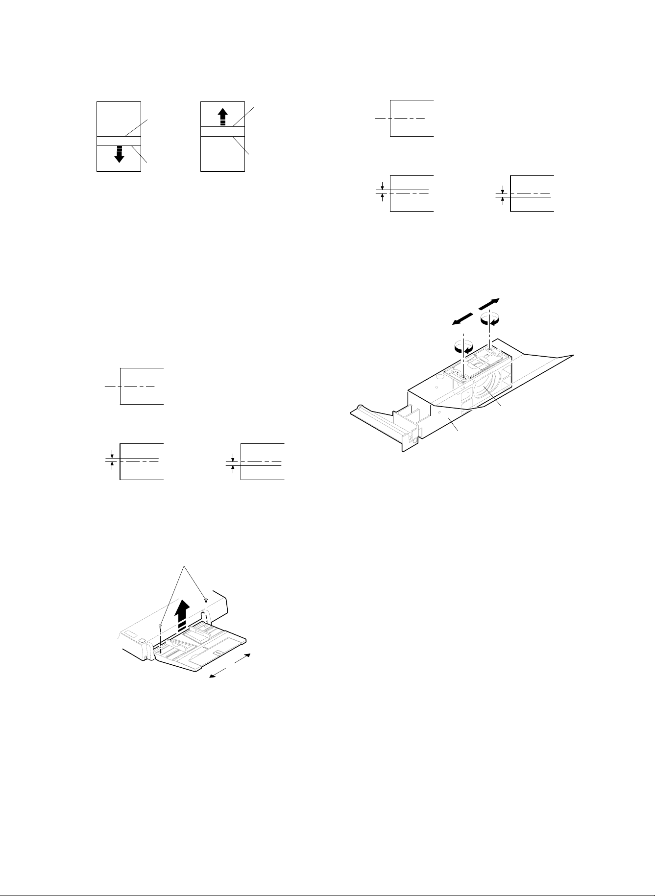
Copy image
Center
Within 2.0mm
a
Copy image
b
Within 2.0mm
(Original)
Center
Original center
(Duplex copy tray)
When the image is shifted to direction of a, loosen two cup screws
and turn the adjustment screw in the direction of A.
When the image is shifted to direction of b, loosen two cup screws
and turn the adjustment screw in the direction of B.
After completion of the adjustment, tighten two cup screws (M4).
e. Copy image center position adjustment in the RADF
unit original tray mode. (The RADF unit original tray
position is changed.)
1
Set the test chart on the RADF tray.
2 Select the paper feed tray unit (No. 1), and make a copy on A4
(11 × 8.5") paper in the RADF copy mode. Check for the copy
image center shift.
Original center
(Original)
3.0mm or
less
(Copy)
Copy
image
center
3.0mm or
less
(Copy)
Center
copy
image
2mm or
less
(Copy)
Move the lens to A.
Copy
image
center
2mm or
less
(Copy)
Move the lens to B.
Center
copy
image
3 If the center shift is outside the specified range, change the lens
unit installing position back and forth.
B
A
Lens
Lens unit
When the lens unit installing position is changed, be sure to perform
procedures a ∼ e again.
Be sure also to adjust the blank lamp position.
3 If the center shift is outside the specified range, change the RADF
tray unit original width adjustment guide position.
Loosen the screw.
f. Change the lens unit position back and forth. (All copy
modes)
This adjustment is made only when the copy image center shift adjustment cannot be completed with procedures a ∼ e.
1 Set the test chart on the original table using the mark on the
original stopper as the reference.
2 Select the paper feed tray unit (No. 1), and make a copy on A4
(11 × 8.5") paper. Check for the copy image center shift.
(3) Focus adjustment (No. 4/5 mirror unit reference
position adjustment)
The focus adjustment is made by making a normal copy, a reduction
copy, and an enlargement copy with SIM 48-1 (48E, 48D, 48F) and
checking focus.
When replacing the lens or in the case of memory trouble, however,
the method by making copy and checking focus and entering the
adjustment value is not efficient.
In that case, calculate the input value depending on the value displayed on the lens and the table, enter the adjustment value temporarily with SIM 48-3, make copies with SIM 48-1 (48E, 48D, 48F),
check the focus, and enter the final adjustment value.
I. Focus adjustment value input (Temporal adjustment
value input)
Enter the input for each of the normal copy, the enlargement copy,
and the reduction copy with SIM 48-3.
Normally this adjustment is not required.
In this adjustment, the input value is calculated depending on the
value displayed on the lens and the formula and the table, and it is
set.
Therefore, the adjustment value to be entered is not the final adjustment value. It is only a temporary value.
When replacing the lens or in the case of memory trouble, however,
the method by making copy and checking focus and entering the
adjustment value is not efficient.
6 – 31
Page 79

In that case, calculate the input value depending on the value displayed on the lens and the table, enter the adjustment value temporarily with SIM 48-3, make copies with SIM 48-1 (48E, 48D, 48F),
check the focus, and enter the final adjustment value.
The normal copy adjustment value is calculated, the enlargement and
the reduction copy adjustment value are calculated from the table.
Label
(0-L)
(0-i)
901024
O. L +1.2
O. i +2.4
P. NO 12
TOPCON0
Label indication
Production year, month, day
Preset value
a. Normal copy focus adjustment value input method
Calculate the normal copy focus adjustment value.
1
Calculation method: SIM 48-3 (48D) = 60 – (OI × 5)
2 Enter the normal copy focus adjustment value input mode.
C → P → 0 → P → 48-3 → PSW (Execute SIM 48-3.)
Select 48D with the scroll key. (The currently set value is dis-
played.)
The input mode (normal, enlargement, reduction) can be selected
with the scroll key.
3 Enter the calculated value.
Enter the calculated value with the 10-key pad and press the
START button.
b. Enlargement copy focus adjustment input method
1
Calculate the set value from the table A (SIM 48-3-48F).
(Table A)
Set value
Lens OI
–8.8 ∼ –7.6
–7.7 ∼ –6.8 2 2
–6.8 ∼ –6.0 3 3
–6.0 ∼ –5.2 4 4
–5.2 ∼ –4.4 5 5
–4.4 ∼ –3.6 6 6
–3.6 ∼ –2.8 7 7
–2.8 ∼ –2.0 8 8
–2.0 ∼ –1.2 9 9
–1.2 ∼ –0.4 10 10
–0.4 ∼ +0.4 11 11
+0.4 ∼ +1.2 12 12
+1.2 ∼ +2.0 13 13
+2.0 ∼ +2.8 14 14
+2.8 ∼ +3.6 15 15
+3.6 ∼ +4.4 16 16
+4.4 ∼ +5.2 17 17
+5.2 ∼ +6.0 18 18
+6.0 ∼ +6.8 19 19
+6.8 ∼ +7.6 20 20
+7.6 ∼ +8.8 21 21
SIM48-3-48A
SIM48-1-48A
50 – (OI/2 × 5) 60 – (OI/2 × 10)
SIM48-3-48D
SIM48-1-48D
SIM48-3-48B
SIM48-3-48C
SIM48-1-48B
SIM48-3-48C
11
SIM48-3-48E
SIM48-3-48F
SIM48-1-48E
SIM48-3-48F
2 Enter the input mode of the enlargement copy focus adjustment
value.
C → P → 0 → P → 48-3 → PSW (Execute SIM 48-3.)
Select 48F with the scroll key. (The currently set value is displayed.)
The input mode (normal, enlargement, reduction) can be selected
with the scroll key.
3 Enter the calculated value.
Enter the calculated value with the 10-key pad and press PSW.
c. Reduction copy focus adjustment value input method
Calculate the set value (SIM 48-3 (48E)) from Table A.
1
2 Enter the reduction copy focus adjustment value input mode.
C → P → O → P → 48-3 → PSW (Execute SIM 48-3.)
Select 48E with the scroll key. (The currently set value is displayed.)
The input mode (normal, enlargement, reduction) can be selected
with the scroll key.
3 Enter the calculated value.
Enter the calculated value with the 10-key pad and press PSW.
The set values of SIM 48-1 (48E, 48D, 48F) and the set values of
SIM 48-3 (48D, 48F, 48E) are related bi-directionally and the same
with each other. If one side is changed, the other related side will be
automatically changed.
48-3 (48E) = 48-1 (48E)
48-3 (48D) = 48-1 (48D)
48-3 (48F) = 48-1 (48F)
SIM 48-1 (48E, 48D, 48F) is accompanied with copying, and SIM
48-3 (48D, 48F, 48E) is not accompanied with copying.
II. Focus adjustment
In this adjustment, copying is made with SIM 48-1 (48E, 48D, 48F),
the focus is checked, and the adjustment value is entered.
The focus adjustment must be performed for each of the normal, the
reduction, and the enlargement copy.
(Standard) (Unit: lines/mm)
Copy center Corners
Normal (100%) 5.0 4.5
Enlargement (200%) 5.0 4.5
Reduction (50%) 3.2 2.8
a. Normal copy focus adjustment method
Set the resolution test chart (UKOG-0089CSZZ) on the original
1
table, and select A3 (11 × 17") copy pape r .
2 Set to the normal copy focus adjustment mode.
C → P → 0 → P → 48-1 → PSW (Execute SIM 48-1.)
Select 48D with the scroll key. (The currently set values is displayed.)
The input mode (normal, enlargement, reduction) can be selected
with the scroll key.
3 Make a normal (100%) copy and check the resolution.
Center: 5.0 lines/mm
Corners: 4.5 lines/mm
(Note) Be sure to make a copy in the manual copy mode for
checking.
6 – 32
Page 80

(Copy)
Check points
4 If the resolution is not within the above range, change the set
value and check the resolution similarly.
(Enter the set value with the 10-key pad and press the PSW.)
Repeat procedures 3) and 4) until the resolution is within the specified range.
b. Enlargement copy focus adjustment method
Set the resolution test chart (UKOG-0089CSZZ) on the original
1
table, and select A3 (11 × 17") copy pape r .
2 Set to the enlargement copy focus adjustment mode.
C → P → 0 → P → 48-1 → PSW (Execute SIM 48-1.)
Select 48F with the scroll key. (The currently set values is displayed.)
The input mode (normal, enlargement, reduction) can be selected
with the scroll key.
3 Make an enlargement (200%) copy and check the resolution.
Center: 5.0 lines/mm
Corners: 4.5 lines/mm
(Note) Be sure to make a copy in manual copy mode for check-
ing.
4 If the resolution is not within the above range, change the set
value and check the resolution similarly.
(Enter the set value with the 10-key pad and press the PSW.)
Repeat procedures 3) and 4) until the resolution is within the specified range.
c. Reduction copy focus adjustment method
1
Set the resolution test chart (UKOG-0089CSZZ) on the original
table, and select A3 (11 × 17") copy pape r .
2 Set to the enlargement copy focus adjustment mode.
C → P → 0 → P → 48-1 → PSW (Execute SIM 48-1.)
Select 48E with the scroll key. (The currently set values is displayed.)
The input mode (normal, enlargement, reduction) can be selected
with the scroll key.
3 Make a reduction (50%) copy and check the resolution.
Center: 3.2 lines/mm
Corners: 2.8 lines/mm
(Note) Be sure to make a copy in the manual copy mode for
checking.
4 If the resolution is not within the above range, change the set
value and check the resolution similarly.
(Enter the set value with the 10-key pad and press the PSW.)
Repeat procedures 3) and 4) until the resolution is within the specified range.
The set values of SIM 48-1 (48E, 48D, 48F) and the set values of
SIM 48-3 (48E, 48D, 48F) are related bi-directionally and the same
with each other. If one side is changed, the other related side will be
automatically changed.
48-3 (48E) = 48-1 (48E)
48-3 (48D) = 48-1 (48D)
48-3 (48F) = 48-1 (48F)
SIM 48-1 (48E, 48D, 48F) is accompanied with copying, and SIM
48-3 (48E, 48D, 48F) is not accompanied with copying.
(4) Vertical copy magnification ratio adjustment
(lens unit reference position adjustment)
The vertical copy magnification ratio adjustment is made by making a
normal copy, a reduction copy, and an enlargement copy with SIM
48-1 (48A, 48B, 48C) and checking focus.
When replacing the lens or in the case of memory trouble, however,
the method by making copy and checking focus and entering the
adjustment value is not efficient.
In that case, calculate the input value depending on the value displayed on the lens and the table, enter the adjustment value temporarily with SIM 48-3, make copies with SIM 48-1 (48A, 48B, 48C),
check the focus, and enter the final adjustment value.
I. Vertical copy magnification ratio adjustment value
input (Temporal adjustment value input)
Enter the input for each of the normal copy, the enlargement coy, and
the reduction copy with SIM 48-3.
Normally this adjustment is not required.
In this adjustment, the input value is calculated depending on the
value displayed on the lens and the formula and the table, and it is
set.
Therefore, the adjustment value to be entered is not the final adjustment value. It is only a temporary value.
When replacing the lens or in the case of memory trouble, however,
the method by making copy and checking focus and entering the
adjustment value is not efficient.
In that case, calculate the input value depending on the value displayed on the lens and the table, enter the adjustment value temporarily with SIM 48-3, make copies with SIM 48-1 (48A, 48B, 48C),
check the focus, and enter the final adjustment value.
The normal copy adjustment value is calculated, the enlargement and
the reduction copy adjustment value are calculated from Table A.
a. Normal copy magnification ratio adjustment value
input method (Vertical)
1 Calculate the normal copy magnification ratio adjustment value.
Calculation method: SIM 48-3 (48A) = 50 – (OL × 5)
2 Enter the normal copy focus adjustment value input mode.
C → P → 0 → P → 48-3 → PSW (Execute SIM 48-3.)
Select 48A with the scroll key. (The currently set value is displayed.)
The input mode (normal, enlargement, reduction) can be selected
with the scroll key.
3 Enter the calculated value.
Enter the calculated value with the 10-key pad and press the
START button.
b. Enlargement copy magnification ratio adjustment
input method (Vertical)
1 Calculate the set value from the table A (SIM 48-3 (48C)).
2 Enter the input mode of the enlargement copy magnification ratio
adjustment mode.
C → P → 0 → P → 48-3 → PSW (Execute SIM 48-3.)
Select 48C with the scroll key. (The currently set value is displayed.)
The input mode (normal, enlargement, reduction) can be selected
with the scroll key.
3 Enter the calculated value.
Enter the calculated value with the 10-key pad and press PSW.
6 – 33
Page 81

c. Reduction copy focus adjustment value input method
(Vertical)
1 Calculate the set value (SIM 48-3 (48B)) from Table A.
2 Enter the reduction copy focus adjustment value input mode.
C → P → O → P → 48-3 → PSW (Execute SIM 48-3.)
Select 48B with the scroll key. (The currently set value is displayed.)
The input mode (normal, enlargement, reduction) can be selected
with the scroll key.
3 Enter the calculated value.
Enter the calculated value with the 10-key pad and press PSW.
The set values of SIM 48-1 (48A, 48B, 48C) and the set values of
SIM 48-3 (48A, 48B, 48C) are related bi-directionally and the same
with each other. If one side is changed, the other related side will be
automatically changed.
48-3 (48A) = 48-1 (48A)
48-3 (48B) = 48-1 (48B)
48-3 (48C) = 48-1 (48C)
SIM 48-1 (48A, 48B, 48C) is accompanied with copying, and SIM
48-3 (48A, 48B, 48C) is not accompanied with copying.
II. Vertical copy magnification ratio adjustment
In this adjustment, copying is made with SIM 48-1 (48A, 48B, 48C),
the focus is checked, and the adjustment value is entered.
The focus adjustment must be performed for each of the normal, the
reduction, and the enlargement copy.
a. Normal copy focus adjustment method
Set a scale on the original table as shown below.
1
Scale
2 Set to the normal copy magnification ratio adjustment mode.
C → P → 0 → P → 48-1 → PSW (Execute SIM 48-1.)
Select 48A with the scroll key. (The currently set values is displayed.)
The input mode (normal, enlargement, reduction) can be selected
with the scroll key.
3 Make a normal (100%) copy.
4 Compare the copy image size and the actual scale size to calcu-
late the vertical copy magnification ratio correction value.
Vertical copy magnification ratio correction value (%)
Original length – Copy image length
=
If the correction value is not within ±1%, change the set value and
check the copy magnification ratio similarly.
(Enter the set value with the 10-key pad and press the PSW.)
The new adjustment value can be roughly obtained from the following formula:
New adjustment value = Old adjustment value + Vertical copy
Repeat the adjustment procedures until the vertical copy magnification ratio is within the specified range.
Original length
magnification ratio correction value × 10
× 100
100mm scale
(Original)
Copy image
(1mm (1%)
shorter than
the original)
10 20 90 100 110
1mm
10 20 90 100 110
b. Enlargement copy magnification ratio adjustment
method (Vertical)
1
Set a scale on the original table similarly to the normal copy
magnification ratio adjustment.
2 Set to the enlargement copy magnification ratio adjustment mode.
C → P → 0 → P → 48-1 → PSW (Execute SIM 48-1.)
Select 48C with the scroll key. (The currently set values is displayed.)
The input mode (normal, enlargement, reduction) can be selected
with the scroll key.
3 Make an enlargement (200%) copy.
Compare the copy image size and the actual scale size to calculate the vertical copy magnification ratio correction value.
Vertical copy magnification ratio correction value (%)
Original length – Copy image length
=
If the correction value is not within ±1%, change the set value and
check the copy magnification ratio similarly.
(Enter the set value with the 10-key pad and press the PSW.)
The new adjustment value can be roughly obtained from the following formula:
New adjustment value = Old adjustment value + Vertical copy
Repeat the adjustment procedures until the vertical copy magnification ratio is within the specified range.
Original length × 2
magnification ratio correction value × 10
× 100
c. Reduction copy magnification ratio adjustment
method (Vertical)
1 Set a scale on the original table similarly to the normal copy
magnification ratio adjustment.
2 Set to the reduction copy magnification ratio adjustment mode.
C → P → 0 → P → 48-1 → PSW (Execute SIM 48-1.)
Select 48B with the scroll key. (The currently set values is displayed.)
The input mode (normal, enlargement, reduction) can be selected
with the scroll key.
3 Make a reduction (50%) copy.
Compare the copy image size and the actual scale size to calculate the vertical copy magnification ratio correction value.
Vertical copy magnification ratio correction value (%)
Original length – Copy image length
=
If the correction value is not within ±1%, change the set value and
check the copy magnification ratio similarly.
(Enter the set value with the 10-key pad and press the PSW.)
The new adjustment value can be roughly obtained from the following formula:
Original length × 0.5
× 100
6 – 34
Page 82

New adjustment value = Old adjustment value + Vertical copy
magnification ratio correction value × 10
Repeat the adjustment procedures until the vertical copy magnification ratio is within the specified range.
The set values of SIM 48-1 (48A, 48B, 48C) and the set values of
SIM 48-3 (48A, 48B, 48C) are related bi-directionally and the same
with each other. If one side is changed, the other related side will be
automatically changed.
48-3 (48A) = 48-1 (48A)
48-3 (48B) = 48-1 (48B)
48-3 (48C) = 48-1 (48C)
SIM 48-1 (48A, 48B, 48C) is accompanied with copying, and SIM
48-3 (48A, 48B, 48C) is not accompanied with copying.
(5) Horizontal copy magnification ratio adjustment
In this adjustment, SIM 48-1 (48G) is used to make a copy, the copy
magnification ratio is checked, and the adjustment value is entered.
a. Horizontal copy magnification ratio adjustment
method
1 Set a scale on the original table similar to the normal copy magni-
fication ratio adjustment.
2 Set to the reduction copy magnification ratio adjustment mode.
C → P → 0 → P → 48-1 → PSW (Execute SIM 48-1.)
Select 48G with the scroll key. (The currently set value is displayed.)
The input mode (normal, enlargement, reduction) can be selected
with the scroll key.
3 Make a normal copy (100%).
4 Compare the copy image size and the actual scale size to calcu-
late the vertical copy magnification ratio correction value.
Vertical copy magnification ratio correction value (%)
Orig inal length – Copy image length
=
Original length
If the correction value is not within ±1%, change the set value and
check the copy magnification ratio similarly.
(Enter the set value with the 10-key pad and press the PSW.)
The new adjustment value can be roughly obtained from the following formula:
New adjustment value = Old adjustment value + Vertical copy
magnification ratio correction value × 10
Repeat the adjustment procedures until the vertical copy magnification ratio is within the specified range.
× 100
(Example 1)
Copy A
Shorter than
the actual size
Scale
(Original)
(Example 1)
Copy B
Longer than
the actual size
10 20 90 100 110
10 20 90 100 110
10 20 90 100 110
(6) Uniformity adjustment
Make a half tone copy in the normal photo copy mode. Move exposure adjustment plates a, b, and c in the directions of A and B. When
the plate is moved in the direction of A, the exposure becomes dark.
When the plate is moved in the direction of B, the exposure becomes
light.
(Example) When a copy shown below is made, move the front expo-
sure adjustment plate in the direction of B to make exposure balance.
Less exposure
Paper exit direction
Half tone copy
(Note) Do not move the exposure adjustment plates further in the
direction of B from the reflector edge. (If moved, the AE
sensor detection area is changed, and the AE copy mode
density becomes improper.)
Scale
Move exposure
adjustment plates
6 – 35
Page 83

(7) Image loss/void area adjustment
Image loss void area specifications
Item Lead edge Rear edge
Image loss 1.0 ∼ 4.5 mm —
Void area 1.0 ∼ 3.0 mm 1.0 ∼ 3.0 mm
Image shift from paper 0±1.5 mm —
Use SIM 50-01 or 50-02 for the lead edge image loss/void area
adjustment and the rear edge void area adjustment in the duplex
copy mode.
(Normal copy mode) Image loss: 1 ∼ 4.5mm
Void area: 1 ∼ 3mm
4 Measure the distance between the copy lead edge and the image
(scale) lead edge in each copy. Obtain 50A (RRC-A) and 50B
(RRC-B) from the following formula:
L2 L1
MHP (OFF)
RRC timer set
A
D
Image lead edge position
A: 50A data (RRC-A)
B: 50B data (RRC-B)
C: 50C data (RRC ON ~ PSBPK OFF)
D: 50D data (Blank lamp OFF)
E: 50E data (Blank lamp ON)
RRC ON PSBRK OFF
BC
Resist roller rotation start
Image area
Paper size
E
(When SIM 50-01 is used for adjustment)
Adjustment procedure
1 Set a scale and A3 (11 × 17") paper on the original table as shown
below:
Scale
White paper
Blank
Scale image lead edge
Normal copy (100%)
Scale image lead edge
Enlargement copy (200%)
• L1: 200% lead edge shift amount [mm]
• L2: 100% lead edge shift amount [mm]
• 50A (RRC-A): 4.72222 × (L1 – L2)
• 50B (RRC-B): 7.2202 × L2 – 3.6101 × L1
5 Enter the obtained values of 50A (RRC-A) and 50B (RRC-B) with
the 10-key pad, and press the START button. (Similarly with (3).)
6 Make a copy in each magnification ratio of 200%, 100% and 50%.
Check for variations in the paper lead edge between different
ratios. (Within about 1.0mm)
If there is an excessive variation, change the value of 50A.
If the preset value of 50A (RRC-A) is not proper, the image lead edge
position differs in different copy magnification ratio. The value of 50B
(RRC-B) is used for adjusting RRC ON timing to fit the drum image
lead edge and the transfer paper lead edge.
7 Make a normal copy, and check that the copy image lead edge
position is within 0 ±1.5mm from the paper edge. If the image lead
edge position is not within the above range, change the value of
RRC-B and repeat the adjustment until it is within the above
range.
(Note) The image loss adjustment value in the above is just for
the adjustment, and not the final adjustment value.
2 Enter the SIM 50-02 mode.
The rea dy lam p light s up and th e pre viously se t val ue (1 ∼ 99) is
displayed.
Content of 50A (RRC-A)
3 Set 50A, 50 B , 50D, and 50E t o "0 " and C to " 10." Make a cop y i n
each magnification ratio of 100% and 200%.
• (Make copies with the RADF section open.)
6 – 36
Paper edge
10 20 30 40
Image lead edge position
0±1.5mm
50
Normal copy
60
(100%)
Page 84

8 With the RADF open, make a copy. Enter the normal copy lead
edge void area adjustment value (50D) with the 10-key pad so
that t he black b ac kg r ou nd secti on edge is a t 1 ∼ 3 mm of the copy
scale image.
When a copy is made, the key input value is set. The change in
the set value by 1 corresponds to about 0.5mm in the void area.
The greater the set value is, the greater the void area is.
Void area
1 ~ 3mm
Void area
3±1mm
Copy scale image
Paper rear edge
Paper lead edge
Image loss
1 ~ 4.5mm
10 20 30 40
Black background edge
Copy scale image
50
9 Make a normal copy and check that the image loss and the void
area are within the specified range.
(Standard range)
Image loss: 1 ∼ 4.5mm
Void area: 1 ∼ 3mm
F Set a scale and A4 (11 × 8.5") paper on the original table as
shown below.
10 20 30 40
Normal copy (100%)
50
H Press the CLEAR key to cancel SIM 50-01.
(Note) When the set value of SIM 50-01 50A (RRC-A) or 50B
(RRC-B), be sure to adjust the copy lead edge void area
adjustment.
(When SIM 50-02 is used for adjustment)
The keys and display functions are the same as SIM 50-01. In SIM
50-02, L1 and L2 values are directly set for simple lead edge adjustment.
The void area adjustment can be performed similarly with SIM 50-01.
Adjustment procedure
1 Set a scale and A4 (11 × 8.5") paper on the original table as
shown below.
Scale
White
paper
A4 (11" x 8.5")
G Make a normal copy and check that the rear edge void area is
within the range of 3±1mm. If not, change the value of 50E so that
it is in the above range.
(Make a copy with the RADF open.)
Scale
White paper
Blank
2 Enter the SIM 50-2 mode.
When the ready lamp lights up, the previously set value (1 ∼ 99) is
displayed. Content of 50A (RRC-A)
3 Set 50A, 50 B , 50D, and 50E t o "0 " and C to " 10." Make a cop y i n
each magnification ratio of 100% and 200%.
• Make copies with the RADF open.
• Select the input content with the scroll key.
4 Measure the distance between the copy lead edge and the image
(scale) lead edge in each copy. Obtain 50A (RRC-A) and 50B
(RRC-B) from the following formula:
6 – 37
Page 85

• L1: 200% lead edge shift amount [mm]
• L2: 100% lead edge shift amount [mm]
• 50A (RRC-A) = L1 × 10
• 50B (RRC-B) = L2 × 10
L2 L1
Scale image lead edge
Scale image lead edge
(8) Blank lamp position adjustment
This adjustment must be performed after completion of the copy
image center position adjustment.
1 Set A3 (11 × 17") white paper on the original table, and make a
reduction copy (64%) on A4 paper with RADF open.
2 Measure the black background section size at either side of the
copy, and adjust the blank lamp unit position back and forth so
that the difference in the sizes is within 1mm.
Adjustment screw: 1 rotation = 0.5mm change
1/2 rotation = 0.25mm change
A
B
(A-B)
1mm
Normal copy (100%)
Enlargement copy (200%)
5 Enter the obtained values of 50A (RRC-A) and 50B (RRC-B) with
the 10-key pad, and press the START button. (Similarly with 3 .)
6 Adjust 50C, 50D, and 50E similarly with SIM 50-1.
Void area
1 ~3mm
Paper lead edge
Image loss
1 ~ 4.5mm
10 20 30 40
background edge
Black
Copy scale image
50
Normal copy (100%)
6 – 38
Page 86

4. Image forming section
Image forming section adjustment list
Section Content Details Method
A Photoconductor
drum unit
B Charger unit (1) Transfer charger current
C Cleaner unit (1) Cleaning blade position
D Developing unit (1) Doctor gap adjustment Change the doctor position to adjust.
E Waste toner
collection unit
A. Photoconductor drum unit
(1) Photoconductor drum sensitivity setting
When the photoconductor drum is replaced, be sure to set the sensitivity class with this simulation.
Enter the code number corresponding to the sensitivity class to be
set, and press the START button. The code is displayed on the
COPIES MADE display.
SIMULATION NO. 26-7
DRUM SENSITIVITY SETUP
INPUT 1~3
The sensitivity level is displayed on the label attached inside the
photoconductor drum.
The top digit of the number shows the sensitivity level. Set this number.
Sensitivity level "1" is the lowest sensitivity, "3" is the highest.
(2) Photoconductor drum correction counter reset
When the photoconductor drum is replaced, be sure to reset the
photoconductor drum correction counter.
1) Execute SIM 24-7.
SIMULATION 24-7
(1) Photoconductor drum
sensitivity setting
(2) Photoconductor drum
correction counter reset
adjustment
(2) Pre-transfer charger
current adjustment
(3) Main charger current
balance adjustment
(4) Main charger voltage
adjustment
(5) Separation charger
voltage adjustment
adjustment
(2) Developing roller main
electrode position
adjustment
(3) Developing bias voltage
adjustment
(4) Toner concentration
adjustment
(5) Developer counter reset Use SIM 42 to reset the developer counter.
(1) Waste toner full detection
level adjustment
a Manual copy mode main charger
current balance adjustment
a Manual copy mode main charger
voltage adjustment
b Photo copy mode main charger
voltage adjustment
c Toner save copy mode main
charger voltage adjustment
Indicates the
sensitivity level.
1 2 3 4 5 6 7 8 9 10
Set SIM 26-7 set value to the sensitivity No.
of the installed photoconductor drum.
Reset the photoconductor drum correction
counter with SIM 24-7.
Change SIM 8-6 set value to adjust the
output current.
Execute SM 8-5 and adjust VR on the high
voltage PWB to adjust the output current.
Execute SIM 8-2 to perform the main
charger unit current balance adjustment.
Change SIM 8-2A set value to adjust the
output voltage.
Change SIM 8-2B set value to adjust the
output voltage.
Change SIM 8-2C set value to adjust the
output voltage.
Change SIM 8-7 set value to adjust the
output voltage.
Change the cleaning blade positioning plate
position to adjust.
Change the developing roller main
electrode positioning plate position to adjust.
Execute SIM 8-1 set value and adjust VR
on the high voltage PWB to adjust the
output voltage.
Use SIM 25-2 to set the initial density.
Change the waste toner detection spring
tension adjustment nut position to adjust.
11
OPC DRUM CORRECTION COUNTER CLEAR
ARE YOU SURE ?
1. YES 2. NO
6 – 39
Page 87

B. Charger unit
Adjustment list
No. Item Mode Voltage Current Current balance (F/R) SIM Remark
1 Main charger current balance adjustment 10µA or less 8-2A
2 Main charger voltage adjustment Normal –750±5V 8-2A
Photo –490±5V 8-2B
Toner save –645±5V 8-2C
3 Pre-transfer discharger current adjustment +15±3µA7µA or less 8-5
4 Transfer charger current adjustment –55±5µA7µA or less 8-6
Charger voltage adjustment +440±20V
5
8-7
Separation corona adjustment for sea level
Sea level
Connect connector CN2
(High voltage section)
Output voltage
0 ∼ 2000 m Connect 1 pin and 4 pin. AC6.00±0.2KV
2000 ∼ 300 0 m No connection AC5.25±0.2KV
3000 m ∼ Connect 3 pin and 6 pin. AC5.00±0.2KV
Tools
Electrode sheet (UKOG-0110FCZZ)
UK0G-0110FCZZ
UKOG-0110FCZZ
(1) Transfer charger current adjustment
Remove the developing unit from the copier.
1
2 Pull out the process unit from the copier, and remove the cleaner
unit, the transfer/separation charger unit, and the main charger
unit.
3 Remove the photoconductor drum from the process unit, and use
rubber bands and tapes to install the electrode sheet.
(It is advisable to use an old, needless drum.)
4 Install the photoconductor drum to which the electrode sheet is
installed to the process unit.
Electrode sheet harness (DHAI-0304FCZZ)
Orange
White
White
A
Red
Blue
Black
(Microswitch)
(QSW-M0118FCZZ)
Orange
White
Orange
PHOG-0007FCZZ
QTIPH0017FCZZ
(A section wiring diagram)
300KΩ X 2
(VRN-RT2EK304F)
Blue
Black
Green
Blue
Black
Yellow
Red
(QCLIZ0005FCZZ)
(QCLIZ0006FCZZ)
(QCLIZ0010FCZZ)
(QCLIZ0004FCZZ)
(QCLIZ0002FCZZ)
5 Install the photoconductor drum unit into the copier so that the
electrode sheet lead wire can be extended from the developing
unit side.
6 Clean the transfer charger wire, and install the transfer/separation
charger unit into the copier.
(Do not install the main charger.)
7 Connect the electrode sheet, the electrode harness, and the digi-
tal multi-meter. (Or connect to an ammeter.)
6 – 40
Page 88

8 With the front cabinet opened (the front cabinet switch OFF), turn
on the main switch to execute SIM 8-06.
9 Manually turn on the front cabinet switch.
F Measure the drum current on the front frame side and on the rear
frame side.
• When the microswitch is OFF: The drum current on the front
frame side is displayed.
• When the microswitch is ON: The drum current on the rear
frame side is displayed.
(OFF)
N/C
N/O COM
N/C
N/O COM
Check that the difference of current between the front and the rear
frame sides is 7.0A or less. If the difference exceeds 7.0A, the
charger unit is defective. Replace the charger unit with a new one.
G Change the set value of SIM 8-6 so that the transfer charger
output current is –55 ±3µA.
Adjustment range: 11 ∼ 56
(ON)
(Note) Check that the black grip is completely grounded to the cop-
ier chassis.
When UKOGE0043CS01 is used
Knob 1: Set to DCmA.
Knob 2: Set to 2.
Red grip: Connect to c .
Blue grip: Connect to d .
When a direct ammeter is used
Red grip: Connect to d of the direct ammeter.
Blue grip: Connect to c of the direct ammeter.
(2) Pre-transfer charger current adjustment
Perform procedures of (1)-1 to 5 .
1
2 Clean the pre-transfer discharger wire, and install to the copier.
(Do not install the main charger.)
3 Connect the electrode sheet, the electrode harness, and the digi-
tal multi-meter. (Or connect to an ammeter.)
4 With the front cabinet open (the front cabinet switch ON), turn on
the main switch to execute SIM 8-05.
5 Manually turn on the front cabinet switch.
6 Measure the drum current on the front frame side and on the rear
frame side.
• When the microswitch is OFF: The drum current on the front
frame side is displayed.
• When the microswitch is ON: The drum current on the rear
frame side is displayed.
Copier chassis
(No coating)
R
Yellow grip
Black grip
Black
Blue
F
Green grip
Orange
White
White
Red
Orange
(Microswitch)
(ON)
N/C
N/O COM
(OFF)
N/C
N/O COM
Check that the difference of current between the front and the rear
frame sides is 7.0µA or less. If the difference exceeds 7.0µA, the
charger unit is defective. Replace the charger unit with a new one.
7 Adjust the pre-transfer discharger output adjustment volume so
that the PTHVG output current is +15 ±3µA.
*
*
*
2
20
200
Digital multi meter
(UKOGE0043FC01)
(DCmA)
Blue grip
Red grip
6 – 41
Adjustment
VR
*
: Never touch these VR's.
*
Page 89

(3) Main charger current balance adjustment
Check only the difference (balance) of the drum current on the front
frame side and on the rear frame side.
1 Perform procedures of (1)-1 to 5 .
2 Clean the pre-transfer discharger wire, and install to the copier.
(Do not install the transfer/separation charger.)
3 Connect the electrode sheet, the electrode harness, and the digi-
tal multi-meter. (Or connect to an ammeter.)
4 With the front cabinet open (the front cabinet switch OFF), turn on
the main switch to execute SIM 8-02.
5 Manually turn on the front cabinet switch.
6 Measure the drum current on the front frame side and on the rear
frame side.
• When the microswitch is OFF: The drum current on the front
frame side is displayed.
• When the microswitch is ON: The drum current on the rear
frame side is displayed.
1 Install all the units of the developing unit, the photoconductor
drum unit, the charger unit., etc.
(Do not use the electrode sheet for the drum.)
2 Set a digital multimeter range to DCV. (Use a digital multimeter
which allows measurement up to DC1000V.)
3 Connect the digital multimeter to the grid voltage output check pin
(GB CP).
4 Turn on the main switch and execute SIM 8-02A (normal mode),
8-02B (photo mode), and 8-02C (toner save mode) to check the
output voltage.
The grid output voltage set value is displayed on the COPIES MADE
display in 3 digits.
Select the voltage mode (copy mode) with the scroll key.
(OFF)
N/C
N/O COM
Check that the difference of current between the front and the rear
frame sides is 10.0µA or less. If the difference exceeds 10.0µA,
use the height adjustment function provided in the process unit to
adjust.
N/C
N/O COM
(ON)
(4) Main charger grid voltage adjustment
Measure the output at the check pin on the high voltage PWB, and
adjust it to the range shown below.
Adjustment output Simulation Adjustment value
MC grid voltage (N) 8-2A –750±5V
MC grid voltage (P) 8-2B –490±5V
MC grid voltage (T/S) 8-2C –645±5V
(5) Separation charger voltage adjustment
This adjustment does not use the electrode sheet.
1 Install all the units of the developing unit, the photoconductor
drum unit, the charger unit., etc.
2 Connect a digital multimeter to the SHVG output check pin (BCDC
CP).
3 Set the digital multimeter to DCV range.
4 Turn on the main switch and execute SIM 8-07. (SHVG turns on
for 30 sec.)
5 During execution of the simulation, adjust so that the separation
charger output monitor voltage (bias voltage) is +440±20V.
6 – 42
Page 90

Adjustment output Simulation Adjustment value
Separation charger DC voltage 8-7 +440±20V
C. Cleaning unit
(1) Cleaning blade position adjustment
The cleaning blade operates in synchronization with rotation of the
photoconductor drum and moves back and forth in the shaft direction
of the photoconductor drum.
When the cleaning blade makes reciprocating motion, its motion must
be centered so that it does not hit the left or right block or that there is
no large clearance.
Change the cleaning blade positioning plate fixing position so that the
cleaning blade does not make contact with the left and the right
blocks when the cleaning blade slide arm is moved manually.
Since the separation charger output is controlled to a constant level, it
increases at a high altitude, operating the current limiter. Therefore,
adjust the voltage as shown below. (The other high voltage outputs
are of constant-current control and require no adjustment.)
Altitude
0 ∼ 2000 m 1-4 6.00±0.2KV ← When
2000 ∼ 3000 m OPEN. Disconnect the
3000 m ∼ Replace 3-5 short pin. 5.00±0.2KV
High voltage PWB CN2
short pin No.
connector.
Voltage
5.25±0.2KV
shipping
D. Developing unit
(1) Doctor gap adjustment
Remove the toner joint cover, the developing unit cover, and the
1
drive section cover.
CN2
6 – 43
Page 91

2 Loosen the DV doctor fixing screws. (2 screws on the rear frame
side, 2 screws on the front frame side)
(2) Developing roller main electrode position adjustment
Remove the fixing screws (4 pcs.) of the developing unit cover
1
and the toner joint cover, and remove the joint cover.
Transformer fixing screw
Doctor fixing screw
3 Turn the developing roller and fit the mark at the rear end of
the developing roller drive side with the DV doctor lead edge.
Insert a 0.55mm clearance gauge into the clearance of 50mm ∼
80mm from the DV doctor edge.
50mm
30mm
2 Tie a string to a pin or a needle.
30mm
50mm
Mark
4 Press the DV doctor in the direction of arrows, and tighten the
fixing screw of the DV doctor. (Both in the front and the rear side)
5 Check that there is an clearance at 50mm ∼ 80mm from eit h er
side edge of the DV doctor is 0.55
(Note) When inserting a thickness gauge, be careful not to
scratch the DV doctor and the MG roller.
0.55mm
+0.05
-0.02
+0.05
mm. (2 positions)
−0.02
Mark
3 Hold the string and move the needle toward the MG roller. (Do not
use a paper clip, which is too heavy to make correct adjustment.)
(Put the developing unit horizontally for this procedure.)
4 Mark the position where the needle makes contact with the MG
roller.
6 – 44
Page 92

5 Measure the distance from the mark to the developing unit guide
surface. Check that the distance is 17.8mm (Japan) ±0.2mm.
If the distance is not as specified above, loosen the fixing screw of
the main electrode adjustment plate, and change the main electrode adjustment plate position.
17.8mm
17.8mm
17.8mm
Main pole adjustment
plate fixing screw
6 Repeat procedures 3 ∼ 5 until the condition of 5 is satisfied.
(3) Developing bias voltage adjustment
1
Set the digital multimeter range to DCV, 300V or above.
2 Put the test rod between the high voltage unit DV bias output
check pin (BSCP) and the chassis (GND).
3 Execute SIM 8-1. (The DV bias voltage is outputted for 30 sec.)
4 Change the set value of SIM 8-1 to adjust so that the output
voltage is –200 ±5V.
Adjustment range: 3 ∼ 56 (–51V ∼ –350V)
When developer is replaced, the initial toner concentration must be
set again.
(Automatic toner concentration adjustment)
Execute SIM 25-2.
The main motor rotates to stir the DV unit. After 3 min from starting
stirring, toner concentration is sampled 16 times for 8 sec. The average value is stored in the RAM as the toner concentration reference
value.
This value is used as the threshold level for toner concentration control.
(5) Developer counter reset
When developer is replaced, the developer counter must be reset
with SIM 42.
SIMULATION NO. 42
DV COUNTER CLEAR
ARE YOU SURE ?
1. YES 2. NO
E. Waste toner collection unit
(1) Waste toner full detection level adjustment
When the waste toner bottle is full, the waste toner bottle weight
sensor (TNF) senses it.
When waste toner (collected toner) weight reaches about 1,320g in
the bottle, the sensor sense it.
Waste toner bottle weight: About 300g
Collected toner weight: About 1320g
Full detection level: Total 1620g
1 Before adjusting the waste toner bottle weight sensor installing
position, prepare a waste toner bottle of about 1620g (with water,
etc. in it).
2 Remove the waste toner bottle which is installed to the copier, and
install the waste toner bottle (1,620g with water in it) on the waste
toner bottle base.
3 When the waste toner is full, the LED on the main PWB is OFF.
Turn the bolt so that the LED lights up when the bottle is put on
the base, and turn the bolt counterclockwise until the LED goes
off.
DV bias voltage adjustment VR
(4) Toner concentration adjustment
SIMULATION NO. 25
INPUT 1~2
1. Toner concentration SENSOR MONITOR
2. AUTO DV ADJUSTMENT
LED
Plate
6 – 45
Page 93

5. Fusing/paper exit section
Adjustment list
Content Method
A Fusing paper guide
position adjustment
B Fusing temperature
setting
C Fusing pressure
adjustment
D Curl correction
amount adjustment
E Switchback gate A
position adjustment
F Fusing roller rotating
speed adjustment
A. Fusing paper guide position adjustment
The angle of paper entry into the fusing section depends on the
position of the fusing paper guide.
Adjust the fusing paper guide position so that paper enters the fusing
section at a proper angle.
1) Fit the edge section of the fusing guide positioning plates (2 pcs.
at the right and the left) with the long part of the fusing frame
marking. (Standard position)
Change the pre-fusing paper guide
height to adjust.
Set SIM 43-1 according to the
destination.
Change the fusing pressure
adjustment screw position to adjust.
Rotate the curl correction knob to
adjust tue correction amount.
Change the switchback gate A drive
solenoid position to adjust.
Change the set value of SIM 43-3 to
adjust. (Default = 16)
B. Fusing temperature setting
Use SIM 43-1 to set the fusing temperature.
Setting must be made either of the single copy mode and the duplex
copy mode.
Selection of the single copy mode and the duplex copy mode is made
with the scroll key.
Enter the number corresponding to the temperature as shown in the
list below, and press the START button.
(Note) Do not set other than the list below.
SIMULATION NO. 43-1
[1|1.2|1]
INPUT (1-5)
1. 190˚C 2. 195˚C 3.200˚C
4. 205˚C 5. 210˚C
[1→2.2→2]
INPUT (1-9)
1. 170˚C 2. 175˚C 3. 180˚C
4. 185˚C 5. 190˚C 6. 195˚C
7. 200˚C 8. 205˚C 9. 210˚C
[1→1.1→2] SETTING : PRESS KEY.
Destination
Japan (15A) specification 205˚C 205˚C
Japan (20A) specification 200˚C 200˚C
EX inch series 200˚C 180˚C
EX AB series 205˚C 205˚C
Copy mode
Normal Duplex
2) Slide the fusing guide fully upward to bring it in contact with the
fusing guide positioning plate, and fix it.
When wrinkles or jams occur, change the position as necessary.
C. Fusing pressure adjustment
It is not required to adjust the fusing pressure. However, arrange as
follows so that the specified fusing pressure is provided.
1) Remove the fusing pressure level fixing screws (1 on the front
frame, 1 on the rear frame).
6 – 46
Page 94

2) Release the fusing pressure lever, and tighten the fusing pressure
nuts (1 on the front frame, 1 on the rear frame) completely.
(With the max. pressure)
When the curl correction adjustment dial is turned clockwise, the curl
correction belt tension is increased, and vice versa.
The tension can be changed from the stand position according to the
situation. When thick paper is used, increase the tension. When thin
film is used, decrease the tension.
When the curl correction belt tension is too strong or too weak, curls
may occur. If this adjustment is improper, paper jams may occur in
back copy.
E. Switchback gate A position adjustment
This is to adjust the operating angle of switchback gate A for normal
switching of paper path in the duplex copy mode and the normal copy
mode.
Change the switchback gate A solenoid installing position and adjust
the operating angle of the switchback gate A.
If this adjustment is improper, paper jams may occur.
1) Change the switchback gate A solenoid installing position to adjust so that the switchback gate A surface is levelled when the
switchback gate A solenoid is manually turned on.
If the fusing pressure is insufficient, or if there is an unbalance between the fusing pressures on the front and the rear frame, wrinkles
and image distortion may result.
D. Curl correction amount adjustment
The paper curl produced in the fusing section in the front surface
copy in the duplex copy mode is adjusted by the paper curl correction
belt to allow smooth paper transport and copying of the back surface.
The curl correction amount is adjusted by changing the curl correction
belt tension.
1) Turn the curl correction adjustment dial to set the arrow section
horizontally. (Standard position)
A A
6 – 47
Page 95

F. Fusing roller rotating speed adjustment
This adjustment is performed to provide a proper paper transport
speed in the fusing section for the transfer section paper transport
speed.
1) Execute SIM 43-3.
2) Enter the set value "2" (default) with the 10-key pad and press the
START button.
The set value can be selected in the range of 1 ∼ 21. The greater
the value is, the grea ter the fusing section paper trans port speed
is. The smaller the set value is, the smaller the transport speed is.
If the copy image is blurred or lacked in the copy paper rear edge,
decrease the fusing section paper transport speed.
6. Switchback section
A. Switchback gate B position adjustment
This is to adjust the operating angle of switchback gate B for normal
switching of paper path in switchback.
Change the switchback gate B solenoid installing position and adjust
the operating angle of the switchback gate B.
If this adjustment is improper, paper jams may occur.
1) Change the switchback gate B solenoid installing position to adjust so that the distance between the switchback gate B lead edge
and the switchback paper guide surface is 1.0±0.5 mm. when the
switchback gate B solenoid is manually turned on.
1.0±0.5mm
6 – 48
Page 96

7. Duplex section
Adjustment list
Content Method
A Air pressure check and adjustment a Suction air pressure
check/adjustment
b Blower air pressure check Use SIM 6-2 to rotate the blower fan to check the pressure.
B Paper width alignment plate position
adjustment
C Paper transport direction alignment
plate position adjustment
Use SIM 6-2 to rotate the suction fan to check the pressure,
and change the air pressure adjustment plate position.
Change the set value of SIM 52-1 to adjust.
Change the set value of SIM 52-2 to adjust.
A. Air pressure check and adjustment
a. Suction air pressure check and adjustment
b. Blower air pressure check
1 Check the pointer of the air pressure meter indicates "0"
(mmH2O). If it does not indicate "0," turn the correction knob to
set to "0."
Air pressure meter and tube: (UKOG-0178FCZZ)
Pressure measurement nozzle: (UKOG-0179FCZZ)
[Suction pressure measurement value]
(Blue)
40
60
80
20
100
Correction tab
2 Place A4 paper (11 × 8.5") on the duplex tray suction belt.
[Blower pressure measurement value]
(Red)
40
60
80
20
100
6 Measure the suction air pressure and the blower air pressure.
Check that the pressures are within the specified range.
<Blower>
40~70mmH20
<Suction>
40~70mmH20
3 Insert the duplex tray unit into the copier.
4 With the front cabinet open, manually turn on the cabinet
open/close detection switch.
5 Execute SIM 6-2 (4).
The blower and the suction fan motors are turned on (open) the
blower and the suction valves of the duplex unit.
If the suction air pressure is insufficient, misfeed may occur. If excessive, double feed may occur.
The suction air pressure can be adjusted by changing the pressure
adjustment plate installing position. However, the blower air pressure
is also changed. When the pressure adjustment plate position is
changed, therefore, be sure to check the duplex blower air pressure.
If the air pressure is outside the specified range, check the following
items.
• Is the blower fan rotating ?
• Do the valves open and close smoothly ?
• Is there any air leakage ?
6 – 49
Page 97

C. Paper width alignment plate stop position
adjustment
This is to adjust the clearance between the paper and the paper width
alignment plate by changing the stop position of the duplex paper
width alignment plate.
1) Enter the SIM 52-1 mode. (Duplex paper width alignment plate
stop position adjustment mode)
SIMULATION NO. 52-1
DUPLEX ALIGNMENT PLATE ADJUSTMENT VALUE SETTING
INPUT DATA (1~99)
2) Open the front cabinet.
3) Press the START button.
4) Pull out the duplex unit, and place paper on the duplex unit longitudinally. (A4 or 11 × 8.5 paper)
D. Paper transport direction alignment plate stop
position adjustment
The duplex paper transport direction alignment plate stop position is
adjusted to set the paper stop position when paper enters the duplex
tray.
1) Enter the SIM 52-2 mode.(Duplex paper transport direction alignment plate stop position adjustment mode)
SIMULATION NO. 52-2
DUPLEX REAR EDGE PLATE ADJUSTMENT VALUE SETTING
INPUT DATA (1~99)
2) Press the START button.
The alignment plate stops at position corresponding to A4 or 11 ×
8.5" paper width.
3) Open the front cabinet.
4) Pull out the duplex unit, and place paper on the duplex unit longitudinally.
0.5 ~ 1.0mm
5) Measure the clearance between the paper width alignment plate
and A4 (11 × 8.5") paper and check that the clearance is 0.5 ∼
1.0mm.
6) If the clearance is not within the above range, insert the duplex
unit into the copier and change the set value and press the
START button.
The paper width alignment plate stops at a position corresponding
to the set value.
The greater the set value is, the wider the paper width alignment
plate is.
Change in the set value by 1 corresponds to about 0.28mm
change in the stop position.
Repeat pr ocedures 4) ∼ 6) un til the cle arance is within the spec i-
fied range.
If this adjustment is not proper, the image position (center position)
may fluctuate in back copies in duplex copy mode, or paper jams may
occur.
(Note) The paper width alignment plate stop position (AB series or
inch series) is determined by the setting condition of SIM26-6
(destination setting).
20 1.5mm
5) Fit the paper transport direction alignment plate with A4 or 11 ×
8.5" paper edge, and check that the distance between the other
paper edge and the paper feed section plate is 20 ±1.5mm.
6) If the distance is not within the above range, insert the duplex unit
into the copier and change the set value and press the START
button.
The paper transport direction alignment plate stops at position
corresponding to the set value.
When the set value is increased, the paper transport direction
alignment plate moves to the left.
Change in the set value by 1 corresponds to about 0.57mm
change in the stop position.
Repeat proced ur e s 4 ) ∼ 6) unti l th e d ist an ce is wi thi n th e s pe cif ie d
range.
If this adjustment is not proper, paper jams may occur in back copies
in duplex copy mode.
(Note) The paper width alignment plate stop position (AB series or
inch series) is determined by the setting condition of SIM26-6
(destination setting).
6 – 50
Page 98

8. RADF section
Adjustment list
Content Method
A RADF horizontal level (skew)
adjustment
B RADF unit clearance adjustment Change the RADF hinge section fixing plate and magnet catch installing
C Original stopper position adjustment (1) Original stopper operating angle adjustment Change the original stopper drive solenoid position and the solenoid
(2) Change the original stopper shaft fixing block installing
position to adjust.
D RADF open/close switch operating
position adjustment
E Sensor sensitivity adjustment (1) Resist sensor sensitivity adjustment Adjust with SIM 53-3A (auto adjustment).
(2) Timing sensor sensitivity adjustment Adjust with SIM 53-3B (auto adjustment).
(3) Paper ext sensor sensitivity adjustment Adjust with SIM 53-3C (auto adjustment).
(4) Paper width sensor sensitivity adjustment Adjust with SIM 53-3D (auto adjustment).
F Original stop position adjustment (1) Normal paper surface mode original stop position adjustment Change the set value of SIM 53-1A to adjust.
(2) Normal paper back mode original stop position adjustment Change the set value of SIM 53-1B to adjust.
(3) Thin paper surface mode original stop position adjustment Change the set value of SIM 53-1C to adjust.
(4) Thin paper back mode original stop position adjustment Change the set value of SIM 53-1D to adjust.
(5) Normal paper step mode original stop position adjustment Change the set value of SIM 53-1E to adjust.
(6) Thin paper step mode original stop position adjustment Change the set value of SIM 53-1F to adjust.
G Motor rotating speed adjustment (1) Paper exit motor rotating speed adjustment Adjust with VR1/VR2 on the RADF control PWB.
(2) Paper feed motor rotating speed adjustment Adjust with VR3/VR4 on the RADF control PWB.
(3) Transport motor rotating sensor phase adjustment Change the transport motor rotating sensor installing position to adjust.
Change the RADF right hinge fixing position to adjust.
position to adjust.
stopper position to adjust.
Original stopper clearance adjustment
Change the RADF open/close detection switch (microswitch) installing
position to adjust.
A. RADF horizontal level (skew) adjustment
By adjusting the RADF horizontal level (skew), the original is
smoothly transported from the paper feed section to the original stop
position (copy position) without skew.
1) Check that the magnet catch on the right is at the center of the
magnet catch plate when the RADF unit is closed.
If not, perform the following procedure.
B. RADF unit clearance adjustment
Clearance between the RADF transport belt and the original table
glass is made uniform and proper to allow paper to be transported
smoothly.
If this adjustment is not proper, troubles of skew, paper jam, image
position shift may occur.
1) Close the RADF unit, and check the clearances (4 positions) between the RADF spacers and the original table glass.
The norma l cle ar a nc e lev el is 0 ∼ 0.5mm.
For simple check, insert a sheet of copy paper (80g/m2) between
the RADF spacer and the original table glass, and close the RADF
unit. Then pull out the paper. If there is some resistance when
pulling out the paper, the clearance is within the specified range. If
not, perform the following procedures.
Adjustment must be made at the four positions (front and back,
left and right).
A
A=B
B
2) Loosen the RADF hinge fixing screw.
3) Shift the RADF unit horizontally with the RADF hinge at the left as
fulcrum.
Repeat pr o cedures 1) ∼ 3) until the condition of 1) is satisfied.
6 – 51
Page 99

5) Change the RADF magnet catch installing positions (the left and
the right on the front frame side).
2) Remove the cabinet.
0~0.5mm
Loosen.
Glass
Magnet catch
RADF spacer
Clearance
0 ~ 0.5mm
Copier metal fixture
Repeat pr o cedures 1) ∼ 4) until the condition of 1) is satisfied.
C. Original stopper position adjustment
(1) Original stopper operating angle adjustment
By adjusting the original stopper operating angle properly, the original
is stopped on the original table and discharged smoothly.
If this adjustment is not proper, trouble of copy image shift and paper
jam may occur.
1) With the original stopper lifted up, check that the original stopper
heigh t from th e original glass surface is 2.0 ∼ 2.8mm.
If the height is not in the above range, perform the following
procedures.
3) Loosen the RADF hinge fixing screw.
Height adjustment screw
RADF hinge fixing screw
4) Turn the RADF height adjustment screw on the rear frame side to
adjust the height of the RADF rear frame side.
For reference, adjust so that the clearance between the hinge and
the hinge angle is about 6.0mm. Actually adjust so that the condition of 1) is satisfied.
Solenoid stopper angle
Original stopper
drive solenoid
A
B
C
D
2.0~2.8mm
0.3~0.8mm
2) Change the original stopper drive solenoid stopper angle installing
position to adjust.
When the position is moved toward A, the original stopper height
is increased. When the position is moved toward B, the height is
decreased.
3) Check that the original stopper height from the original glass surface is 0.3 ∼ 0.8mm when the original stopper drive solenoid is
manually turned on.
If the height is not in the above range, perform the following
procedure.
4) Change the original stopper drive solenoid installing position to
adjust. When the position is moved toward C, the original stopper
height is increased. When moved toward D, the height is decreased.
Repeat procedures 1) ∼ 4) until the conditions of 1) and 3) are
satisfied.
6 – 52
Page 100

(2) Original stopper clearance adjustment
The clearance between the original stopper and the original table
glass is properly adjusted to inhibit the original stopper from entering
the clearance between the original stopper and the original table
glass and to allow the original stopper to move smoothly.
If this adjustment is not proper, paper jams may occur.
1) Loosen the two fixing screws of the original stopper shaft block.
Fixing screw (Loosen.)
Original stopper shaft
block fixing screw
Glass
Original stopper
Paper
2) Insert a sheet of copy paper (80g/m2) between the original table
glass and the original stopper, slide the original stopper to the
original table glass and fix it. This makes a clearance of one sheet
of copy paper.
If the clearance is more than one sheet of copy paper, change the
original table glass installing position. (Slide the original table
glass to the original stopper and fix it.)
3) Execute SIM 2-3 (8) to check the operation of the original stopper.
If the original stopper moves smoothly, it is normal.
D. RADF open/close switch operating position
adjustment
The RADF open/close switch installing position is adjusted so that the
RADF switch operates normally when the RADF is opened/closed.
If this adjustment is not proper, the internal load power is not supplied
when the RADF is closed, and the RADF does not operate.
Slowly close the RADF unit from the full open state.
When the RADF open/close switch is turned on, check that the RADF
spacer height from the original table glass is 25 ∼ 55mm.
If the height is not in the above range, change the RADF open/close
switch installing position.
RADF open/close
detection switch
RADF unit
RADF spacer
E. Sensor sensitivity adjustment
This adjustment is required for the resist sensor, the timing sensor,
the paper exit sensor, and the paper width sensor. The threshold
level is automatically set by SIM 53-3.
1) Enter the SIM 53-3 mode.
2) Select the sensor to be adjusted with the scroll key.
3) Press the PRINT button.
The threshold level is automatically set and displayed.
SIMULATION NO. 53-3
RADF SENSOR ADJUSTMENT
53A: RESIST SENSOR
53B: TIMING SENSOR
53C: PAPER EXIT SENSOR
53D: ORIGINAL WIDTH SENSOR
6 – 53
 Loading...