

Page 1
j
UX-27OOCMUKMC
FO-255OCMUKMC
SHARP’
I
SERVICEMANUAL ,,
._
No. OOZU27OCMUSME
FACSIMILE
\
UX-2700CM
MODEL FO-2550CM
-
CONTENTS
CHAPTER 1, GENERAL DESCRIPTION
[I] Specifications
............................................ 1-I
[2] Operation panel
......................................... I-2
[3] Transmittable documents
..........................
I-3
[4] installation
................................................. I-4
[5] Quick reference guide
...............................
I-9
CHAPTER 2. ADJUSTMENTS
[I] Adjustments
............................................... 2-I
[2] Diagnostics and service soft switch
..........
2-2
[3] Troubleshooting
...................................... 2-l 7
[4] Error code table
....................................... 2-I 8
CHAPTER 3. MECHANISM BLOCKS
[I] General description
.................................. 3-I
[2] Disassembly and assembly
procedures
....................................... 3-4
CHAPTER 4. DIAGRAMS
[I] Block diagram
............................................ 4-I
[2] Wiring diagram
.......................................... 4-2
[3] Point-to-point diagram
............................... 4-3
CHAPTER 5. CIRCUIT DESCRIPTION
[I] Circuit description ..................................
.................
51
[2] Circuit description of control PWB. 512
[3] Circuit description of TEULIU PWB ......... 5-11
[4] Circuit description of
power supply PWB
............................ 5-14
[5] Circuit description of CIS PWB ............... 5-I 5
[6] Color scanner block ................................ 5-I 6
[7] Basis of color ............................................ 5-I 8
CHAPTER 6. CIRCUIT SCHEMATICS AND
PARTS LAYOUT
[I] Control PWB circuit
. . . . . . . . . . . . . . . . . . . ..m....m....m...
61
[2] TEULIU PWB circuit
. . . . . . . . . . . . ..ma..m......m...m.
6-13
[3] Ink sensor PWB circuit
a.....*....Dm....*......... 6-15
[4] Printer PWB circuit
. . . . . . . . . ..*...0.....lJ......li......
6-I 7
[5] Operation panel PWB circuit . ..D.Om . . . . . . . . . _. 6-23
[6] IrDA PWB circuit ..,..D.....,......~,,..,...,..~,...~~.
6-24
[7] Power supply PWB circuit . . .m . . . . ._... .._.D . . . 6-25
CHAPTER 7. OPERATION FLOWCHART
[I] Protocol .....................................................
7-I
[2] Power on sequence
.................................. 7-2
CHAPTER 6. OTHERS
[ I] Service tools . ..D..........~.D~.~........*...~.....*...~...
8-I
[2] IC signal name
. . . . . . . . . . . . . . . ..~0~.~..~...~....~.....~.. 8-6
CHAPTER 9. INK JET PRINTER
[II
PI
PI
WI
PI
PI
VI
PI
PI
Engine specifications
.~~..........D........~..~.~.~‘. 9-I
Abbreviations
. . . . . . . ..~..0#...~......~.~.~................ 9-I
Diagnostic information . . . . . . . . . . ..D...DO.O..e......m.
9-I
Circuit description
. . . . . . . . . . . . . . ..~..D...~....~......~.. 9-2
Overall troubleshooting of printer PWB .._ 9-7
How to decide the number of the wrong
nozzle . . . . . . . . ..~........D~...~..~..~~...........~..~ 9-10
Waveforms
.,............*~......~.~...~.“~.~.~~..~.....0 9-12
Service checks
. . . . . . . . . . . . ..D.*...m..*......mm0.mm....
9-l 5
IC signal name
. . . ..~...D....0.~..0..~~.~~~~.~.~..~~~~~ 9-I 9
PARTS GUIDE
Parts marked with “&’ is important for maintaining the safety of the set. Be sure to replace these parts with specified ones for
maintaining the safety and performance of the set.
SHARP CORPORATION
This document has been published to be used
for after sales service only.
The contents are subject to change without notice.
Page 2
UX-27OOCMUKMC
FO-255OCMUKMC
- CAUTION FOR BAlTERY REPLACEMENT -
(Danish)
Lithiumbatteri-Eksplosionsfare ved fejlagtig handtering.
Udskiftning ma kun ske med batteri af samme fabrikat og type.
Lever det brugte batteri tilbage til Ieverandoren.
(English)
Danger of explosion if battery is incorrectly replaced.
Replace only with the same or equivalent type
recommended by the equipment manufacturer.
Discard used batteries according to manufacturer’s
(Finnish) VAROITUS
Paristo voi rajahtaa, jos se on virheellisesti asennettu.
Vaihda paristo ainoastaan laitevalmistajan suosittelemaan
tyyppiin. Havita kaytetty paristo valmistajan ohjeiden
(French)
II y a danger d’explosion s’ il y a remplacement incorrect
de la batterie. Remplacer uniquement avec une batterie du
meme type ou d’un type recommande par le constructeur.
Wlettre au rebut les batteries usagees conformement aux
(Swedish)
Explosionsfare vid felaktigt batteri byte.
Anvand samma batterityp eller en ekvivalent
typ som rekommenderas av apparattillverkaren.
Kassera anvant batteri enligt fabrikantens
(German)
Explosionsgefahr bei Vetwendung inkorrekter Batterien.
Als Ersatzbatterien durfen nur Batterien vom gleichen Typ oder
vom Hersteller empfohlene Batterien verwendet werden.
Entsorgung der gebrauchten Batterien nur nach den vom
Hersteller angegebenen Anweisungen.
ADVARSEL !
Caution !
instructions.
mukaisesti.
ATTENTION
instructions du fabricant.
VARNING
instruktion.
Achtung
Page 3

UX-27OOCMUKMC
FO-255OCMUKMC
CHAPTER 1 n GENERAL DESCRIPTION
[I] Specifications
Printing specifications
Print cartridges
Print resolution
Print speed
Paper types
Fax specifications
Automatic dialing
Memory size*:
Automatic document
feeder
Modem speed
Transmission time*
Display
Reception modes
Color: Sharp UX-27CC
Black:Sharp UX-22BC
High:600 x 600 dpi (both color and black)
Normal: 300 x 300 dpi
Color: Up to 2 pages per minute
Black:Up to 3 pages per minute
Index cards, envelopes, labels, transparen-
cies, glossy film, greeting cards, iron-on
transfers, plain, coated, and glossy paper.
Rapid Key Dialing: 38 numbers
Speed Dialing: 61 numbers
512 KB (approx. 42 average pages)
20 sheets max.
14400 bps with automatic fallback to 12000,
9600,7200,4800, or 2400 bps
Approx. 6 seconds (Sharp special mode)
1 B-digit LCD display
Auto/Manual
Horizontal:
200 pels/inch
Vertical:
Standard: 100 lines/inch
Fine /Halftone:
200 lines/inch
Super fine (transmission only):
400 lines/inch
Halftone (grayscale)
64 levels
Applicable telephone line Public switched telephone network
Compatibility ’ ITU-T (CCITT) G3 mode
Configuration
Half-duplex, desktop transceiver
Compression scheme MH, MR, MMR
Scanning method Sheet-feeder CIS (Contact Image Sensor)
Effective printing 8” (203 mm) max.
width
Paper margins Top:55 mm
Bottom:23.7 mm
Input document size Automatic feeding:
Width: 5.8 to 8.5” (148 to 216 mm)
Length: 5.5 to 1 I” (140 to 279 mm)
Manual feeding:
Width: 5.8 to 8.5” (148 to 216 mm)
Length: 5.5 to 39.4” (140 to 1000 mm)
Effective scanning width 8.3” (210 mm) max.
Contrast control
Automatic/Dark selectable
NOTE:The Sharp Color MFP is not able to send or receive
color faxes.
Copying specifications
Resolution
300 dpi
Multiple copies
Up to 99 (monochrome copying only)
Copy reduction/
Monochrome:fiO%, 75%, 120%, 150%
enlargement
Color:50%, 200%
PC scanning specifications
Resolution
Scanning modes
Enhanced 600 dpi
Color/monochrome/grayscale(64 levels)
General specifications
Power requirements 120 V AC, 60 Hz
Operating temperature 50 to 100°F (10 to 35°C)
Operating humidity 30 - 80%RH
Power consumption Stand-by: 8.5 W
Maximum: 40 W
Dimensions Width: 16.0” (406 mm)
Depth: 12.0” (306 mm)
Height: 10.0” (255 mm)
(Without attachments)
Weight Approx. 13.0 Ibs. (5.9 kg)
(without attachments)
* Based on ITU-T Test Chart #I at standard resolution in Sharp
special mode, excluding time for protocol signals (i.e., ITU-T phase C
time only).
As a part of our policy of continuous improvement, SHARP reserves the right to make design and specification changes for procduct
improvement without prior notice. The performance specifications figures indicated are nominal values of production units. There may be some
deviation from these values in individual units.
1-I
Page 4
UX-27OOCMUKMC
FO-255OCMUKMC
[2] Operation panel
I
I
I
I
I
I
I
I
I
I
I
I
I
I
I
I
I
I
I
I
I
I
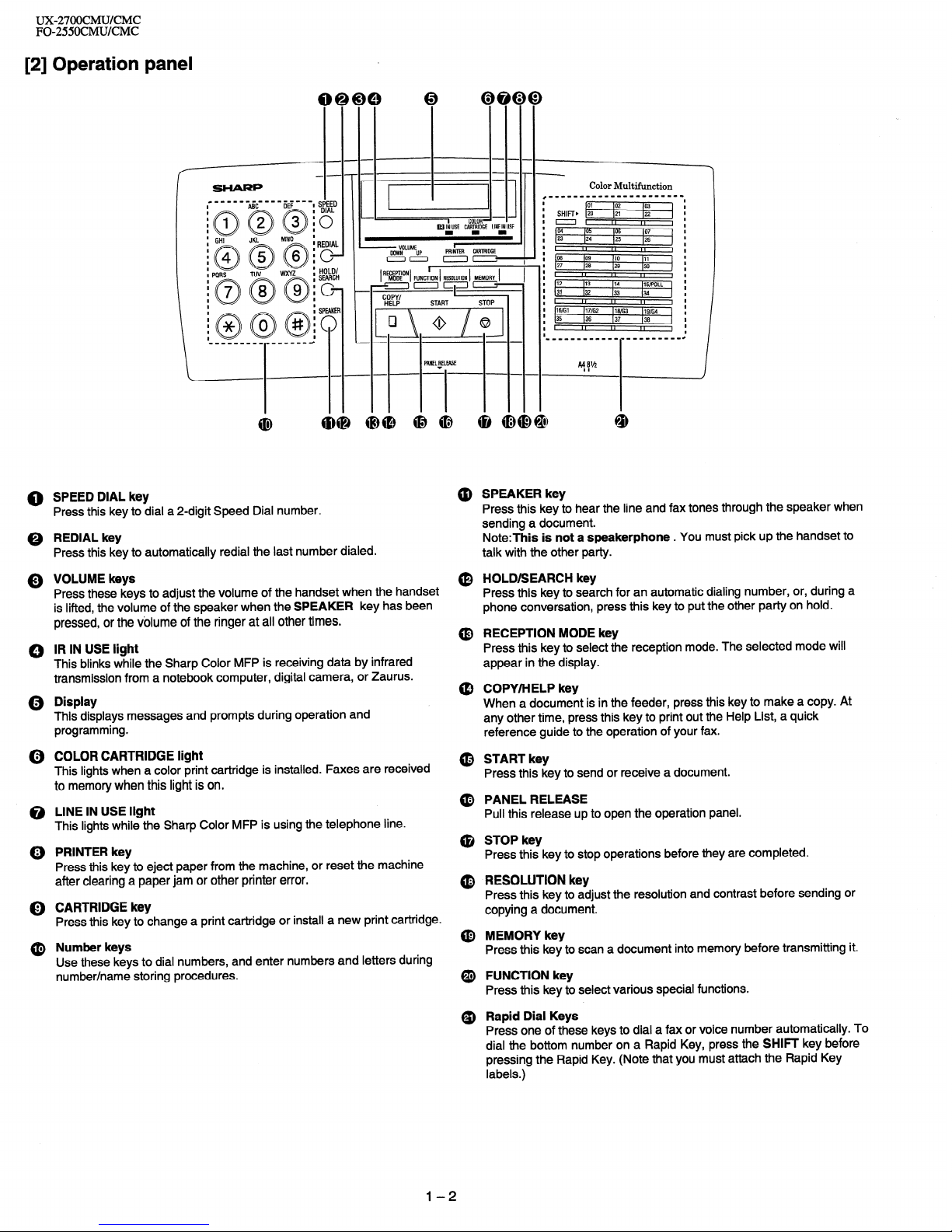
0 SPEED DIAL key
Press this key to dial a 2-digit Speed Dial number.
0 REDIAL key
Press this key to automatically redial the last number dialed.
Q VOLUME keys
Press these keys to adjust the volume of the handset when the handset
is lifted, the volume of the speaker when the SPEAKER key has been
pressed, or the volume of the ringer at all other times.
0 IR IN USE light
This blinks while the Sharp Color MFP is receiving data by infrared
transmission from a notebook computer, digital camera, or Zaurus.
Q Display
This displays messages and prompts during operation and
programming.
(i) COLOR CARTRIDGE light
This lights when a color print cartridge is installed. Faxes are received
to memory when this light is on.
@ LINE IN USE light
This lights while the Sharp Color MFP is using the telephone line.
@) PRINTER key
Press this key to eject paper from the machine, or reset the machine
after clearing a paper jam or other printer error.
0 CARTRIDGE key
Press this key to change a print cartridge or install a new print cartridge.
SHIFT, [vi
==I
04 165 lo6 107
23 124
(25 126
II
,,
,,
p8
lo9 110 111
27 I26
129 130
II
I,
,,
#12 113
114 IlS/POLL
31 132
133 (34
II I, ,,
16ffil )17/G2 116ffi3 )lgffi4
35
136 137 136
II I, ,,
I
I
I
I
I
I
@ Number keys
Use these keys to dial numbers, and enter numbers and letters during
number/name storing procedures.
@ SPEAKER key
Press this key to hear the line and fax tones through the speaker when
sending a document.
Note:This is not a speakerphone . You must pick up the handset to
talk with the other party.
(0 HOLD/SEARCH key
Press this key to search for an automatic dialing number, or, during a
phone conversation, press this key to put the other party on hold.
@ RECEPTION MODE key
Press this key to select the reception mode. The selected mode will
appear in the display.
@ COPY/HELP key
When a document is in the feeder, press this key to make a copy. At
any other time, press this key to print out the Help List, a quick
reference guide to the operation of your fax.
@ START key
Press this key to send or receive a document.
@ PANEL RELEASE
Pull this release up to open the operation panel.
@ STOP key
Press this key to stop operations before they are completed.
@ RESOLUTION key
Press this key to adjust the resolution and contrast before sending or
copying a document.
@ MEMORY key
Press this key to scan a document into memory before transmitting it.
@ FUNCTION key
Press this key to select various special functions.
Q) Rapid Dial Keys
Press one of these keys to dial a fax or voice number automatically. To
dial the bottom number on a Rapid Key, press the SHIFT key before
pressing the Rapid Key. (Note that you must attach the Rapid Key
labels.)
l-2
Page 5

. [3] Transmittable documents
1. Document Sizes
Normal size
width
5.83”.8.5”( 148 - 216 mm)
length
5.04,)-l I”( 128 - 297 mm)
_.--
c-
c-
.-
.-
.-
_f1° .--
c
c-- ---
c-
--
--
--
--
--
-
c-
_-- _--
.-
.-
.-
.--
.-
.-
(Max.)
Letter
size
128mm
1 OOOmm
279mm
L-h
148mm
216mm
216mm
[Normal size]
[Special size]
XX Use document carrier sheet for smaller documents.
* With special sizes, only one sheet can be fed into the machine at a
time. Insert next page into feeder as current page is being scanned.
2. Paper Thickness &Weight
Thickness
2.4x1 0w3- 4.7x1 0m3 inch
ADF IO
(0.06-0.12 mm)
sheets
0.15x1 O-3 Ibs/inch2
Weight
(52-l 04gl m2)
Normal size
(14-28 Ibs)
Thickness
2.4x1 O-3- 3.5x1 0” inch
ADF20 _
(0.06-0.09 mm)
sheets
0.77x1 o-3-
0.11x10⁻³inch
Weight
(52-74.391 m2)
(M-20 Ibs)
Thickness
4.7x1 o-3 - 7.9x1 O9 inch
Special size
(0.12-0.20 mm)
0.15x1 O-3 - 0.20x1 0-31bs/inch2
Weight
(52-l 5791 m2)
3. Document Types
Normal paper
Documents handwritten in pencil (No. 2 lead or softer), fountain pen,
ball-point pen, or felt-tipped pen can be transmitted.
Documents of normal contrast duplicated by a copying machine can
also be transmitted.
Diazo copy (blue print)
Diazo copy documents of a normal contrast may be transmitted.
Carbon copy
Acarbon copy may be transmitted if its contrast is normal.
4. Cautions on Transmitting Documents
Documents written in yellow, greenish yellow, or light blue ink cannot
be transmitted.
Ink, glue, and correcting fluid on documents must be dry before the
documents can be transmitted.
All clips, staples and pins must be removed from documents before
transmission.
Patched (taped) documents should be copied first on a copier and
then the copies used for transmission.
All documents should be fanned before insertion into the feeder to
prevent possible double feeds.
UX-27OOCMUKMC
FO-255OCMUKMC
5. Automatic Document Feeder Capacity
Number of pages that can be placed into the feeder at anytime is as
follows:
Normal size: max. ADF 20 sheets (14 Ibs - 20 Ibs)
Special size: single sheet only (manual feed)
NOTES: l When you need to send or copy more pages than the feeder
limit, place additional pages in feeder when last page in
feeder is being scanned.
l Place additional pages carefully and gently in feeder.
If force is used, double-feeding or a document jam may
result.
6. Readable Width & Length
The readable width and length of a document are slightly smaller than
the actual document size.
Note that characters or graphics outside the effective document scanning range will not be read.
l Readable width
210 mm, max.
I
I
I
I
I
I
I
I
I
I
I
I
I
I
I
I
I
I
I
I
I
I
I
I
I
I
I
I
I
I
I
I
I
I
I
I
I
I
I
I
I
I
I
I
I
I
I
t
/t---t/
Readable width
l Readable length
This is the length of the document sent minus 0.16” (4 mm) from the top
and bottom edges.
1-3
Page 6

UX-27OOCMUKMC
FO-255OCMUKMC
7. Use of Document Carrier Sheet
A document carrier sheet must be used for the following documents.
Those with tears.
Those smaller than size 583”(W) x 504”(L) (148 mm (W) x 128
Make print straight
across paper
E.G.
Place the document
carrier in the document
feeder with the clear film
side down
Direction
of insertion
NOTE: To transmit a carbon-backed document, insert a white sheet of
paper between the carbon back of the document and the document carrier.
l
Those containing an easily separable writing substance (e.g., trac-
ing paper written on with a soft, heavy lead pencil).
NOTES: l When using the document carrier, carefully read the in-
structions written on the back.
l If the document carrier is dirty, clean it with a soft, moist
cloth, and then dry it before using for transmission.
l Do not place more than one document in the carrier at a
time.
[4] Installation
1. Site selection
Take the following points into consideration when selecting a site for this
model.
ENVIRONMENT
The machine must be installed on a level surface.
Keep the machine away from air conditioners, heaters, direct sunlight, and dust.
Provide easy access to the front, back, and sides of the machine. In
particular, keep the area in front of the machine clear, or the original
document may jam as it comes out after scanning.
The temperature should be between 5” and 35OC.
The humidity should be between 30% and 85% (without conden-
sation).
ELE’CTRICITY
120V , 60H2, grounded (3-prong) AC outlet is required.
Caution!
Connection to a power source other than that specified will cause
damage to the equipment and is not covered under the warranty.
If your area experiences a high incidence of lightning or power surges,
we recommend that you install a surge protector for the power and
telephone lines. Surge protectors can be purchased at most telephone
specialty stores.
If the machine is moved from a cold to a warm place...
If the machine is moved from a cold to a warm place, it is possible that
the reading glass may fog up, preventing proper scanning of documents
for transmission. To remove the fog, turn on the power and wait approxi-
mately 2 hours before using the machine.
TELEPHONE JACK
A standard RJII C telephone jack must be
located
near the machine.
This is the telephone jack commonly used
in most homes and offices.
0 Plugging the fax machine into a jack which is not an RJI 1 C jack may
result in damage to the machine or your telephone system. If you do
not know what kind of jack you have, or needed to have one installed,
contact the telephone company.
2. Trays
@ Attach the document
@ Insert the paper tray into the back of the machine as shown.
@ Pull out the original document support and the output tray.
Note: When receiving faxes, copying or printing, do not
let a large number of pages accumulate in the output
tray. This may obstruct the outlet and cause paper jams.
l-4
Page 7

* 3. Connections
@ Handset
@ Telephone line cord
UX-27OOCMUKMC
FO-255OCMUKMC
Connect the handset as shown and place it on the handset rest.
+ The ends of the handset cord are identical, so they will go into
either jack.
,.-. /----.- ,_-,
I
,“- Make sure the
1
i handset cord goes
i
,’ into the unmarked
1
jack on the side of ’
‘:I the machine! ‘:
‘.-i-N
8 Power cord
Plug the power cord into a 120 V, 60 Hz, grounded (3-prong)
AC outlet.
Caution!
Do not plug the power cord into any other kind of outlet.
This will damage the machine and is not covered under the
warranty.
Insert one end of the line cord into the jack on the back of the
machine marked TEL. LINE. Insert the other end into
a standard (FIJI 1 C) single-line wall telephone jack.
Be sure to insert the
telephone line cord into
the TEL. LINE jack.
Do not insert it into
Note:The Sharp MFP is set for touch-tone dialing. If you are
on a pulse dial (rotary) line, you must set the Sharp MFP for
pulse dialing. Press the following keys on the operation panel:
..:.:;~:::>,
0
until
- Press @#/$~ display
Di
shows:
TONE PULSE
TADCONNECTED -
STOP
Note:If your area experiences a high incidence of lightning
or power surges, we recommend that you install surge
protectors for the power and telephone lines.
Surge protectors can be purchased at most telephone
specialty stores.
1-5
Page 8

ux-27OocMU/cMc
FO-2550CMU/CMC
4. Installing a Print Cartrige
Note:lf you receive a fax when a color print cartridge is installed,
the fax will be held in memory and printed out when a black
cartridge is installed.
CARTRIDGE key
START key
@ Press the CARTRIDGE key.
CARTRIDGE
~~~
o The cartridge carrier will move to the center of the print
compartment.
@) Open the front cover of the Sharp Color MFP.
Note on changing cartridges:
When you need to change a print
cartridge, remove the currently
installed cartridge after Step 2 above.
Remove the cartridge by pulling the
knob on the cartridge toward you
until
you
hear a click.
If the cartridge is still useable, insert it
into the cartridge holder on the back of
the machine. Push back on the
cartridge until it snaps into place.
l To prevent the used print cartridge
from drying out, be sure to store it
in the cartridge holder.
@ Remove the new print cartridge from its packaging.
4
@ Gently remove the sticker and transparent tape covering the
copper printhead.
Insert the print cartridge into the cartridge carrier. Push back
on the cartridge until it snaps into place.
Note:If the print cartridge moves loosely in the carrier, it is not
locked into place. Repeat this step.
Close the front
cover.
1-6
Page 9

@ Press the START key.
START
~~
The display on the Sharp Color MFP will show:
5 . Loading Printing Paper
UX2700CMU/CMC
FO-255OCMUKMC
You can load letter or legal size paper in the paper tray. The maximum
number of sheets is:
+ 200for paper from 16 to 20 Ibs. (60 to 80 g/m*)
+ 150for paper from 20 to 24 Ibs. (90 g/m*) (such as coated paper)
SELECT CARTRIDGE
I
Press 1 if you installed a new cartridge, or 2 if you installed an
old cartridge.
@ Press the 3 key if you installed a new black cartridge, or the
4 key if you installed a new color cartridge.
(When installing a previously used cartridge, press the 1 key for
a used black cartridge or the 2 key for a used color cartridge.)
NEW BLACK CART.
NEW COLOR CART.
.The cartridge will return to its home position. If you pressed 3
or 4 for a new cartridge, the Sharp MFP will print a test page
for printhead alignment.
@ If you installed a new print cartridge, look at the test page and
locate the line that comes closest to forming a perfectly straight
line.
In this example, line 13
comes closest to
~ forming a straight line.
0 1 2 3 4 5 6 7 6 9 10 11 12 13 14 15 16 17 16 19 26 21 22 23 24 23 26 27 26 26 36
@
Press these keys on the Sharp MFP:
The display Will show:lALfGN CARTRIDGE 1
1 ENTER (00-30) 15
1
ISTART: PRINT 1
@ Enter the two-digit number of the straightest line on the test
page. (If the number is less than IO, enter a 0 before the
number.) l
Example: Line 13
~~
::qiij::.
The display will show: CLEAN NOZZLES
@
Press the STOP key to return to the time and date display.
STOP
Note:If you have installed a color cartridge, the display will
show the following alternating messages:
ICOLOR CARTRIDGE! 1
1 USE BLACK FOR RX
1
@ Remove the paper cover if it is on the paper tray.
l If you are going to load legal size paper, flip up the paper tray
extender.
,:~::a:,,;:.~:r...,..~...~,.,..~~.~~~~~
.Y..... ../: ..,. :.+:..
::;::::::::::::)y:. ,ii~~i~~~:~i:~i:?~~,~i:
. .:~.+:qy II Flip “p for
..i:i:i:~:w:~~.~W:i.::::a:i:::::?~:~?::~~~:!~:~.
..,........%...h
~. .,...,...,.,.,.,.,..... < . . . . . . .
~ ~ legal paper
8 Fan the paper, and then tap the edge against a flat surface to even
the stack.
@ Pull the paper release plate toward you.
@ Insert the stack of paper into the tray, print side up
l If paper remains in the tray, take it out and combine it into a single
stack with the new paper before adding the new paper.
@ Replace the paper cover on the paper tray.
@Push the paper release plate back down.
l Important Be sure to replace the paper cover before you push the
paper release plate down.
l-7
Page 10

UX-27OOCMWCMC
FO-255OCMUKMC
0 The Sharp Color MFP has been set at the factory to scale the size of
Clearing jammed prining paper
received faxes to letter size paper. If you have loaded legal paper,
you must change the paper size setting to legal. Press these keys:
@ Open the front cover of the Sharp MFP.
~~~
The display will show: PAPER SIZE
Pressl to select LETTER,2 to select LEGAL, or 3 to select A4.
LE-f-l-ER: ~
. .
LEGAL: ,,,, .
0
.@#
A4:
0
.$&@
. . . . . . . .
Press the STOP key to return to the date and time display.
STOP
/
~~~
:iiiiiiiijiiiii:i:i:::::::::
0 Grasp the leading edge of the jammed paper and pull it out of the
machine.
Note:This setting is only for received faxes. To set the paper size for
printing from your computer, see your online Operation Guide.
@ The Sharp Color MFP has been set at the factory to print on plain
paper. If you have loaded coated paper, you must change the media
type setting to COATED. Press these keys:
~~~~
The display will show: MEDIA -ryp~
@ If it is too difficult to pull the jammed paper out from the front of the
machine, remove the paper tray cover, pull the paper release plate
PressI to select PLAIN or 2 to select COATED.
PLAIN COATED s
Q @
:&qg or $y;:;
toward you, and pull the jammed paper out from the back of the
machine.
t
/
,
Press the STOP key to return to the date and time display.
STOP
:::::::,:y::::::::::
/7
$ggpg
.,.,.,.,.,., ..:::::::
. .,. (...,.,.,.,._..
:.:.:+: . . . . . . . ..+........
6. Clearing Paper Jams
Clearing a jammed document
If the original document doesn’t feed properly during transmission or
copying, or DOCUMENT JAMMED appears in the display, first try
pressing the START key. If the document doesn’t feed out, open the
operation panel and remove it.
@ Make sure there are no torn pieces of paper remaining in the
machine.
Important
Do not try to remove a document without opening the operation
panel. This may damage the feeder mechanism.
@ Pull the release marked PANEL RELEASE up and open the
operation panel.
@ Close the front cover. Replace the paper tray cover (if removed),
and then press the paper release plate back down.
0 Remove the document.
@ Press the PRINTER key to reset the Sharp MFP.
PRINTER
\
~
@ Close the operation panel, making sure it clicks into place.
l-8
Page 11

UX-27OOCMUKMC
FO-2550CMUKMC
[5] Quick reference guide
CARTRIDGE
Press: ~
. . . . . . . . . . . . . . . . . . . . . . . . . . . . . .
:.:.:.~:.:.:.:,:.:.:.:.~~~:,:.:,~:.:.:,:.:.:.:
2.
Open the front cover of
the Sharp Color MFP.
3. Remove the current print I-?
P&&&-
7
cartridge.
I
0
If the cartridge is still
useable, insert it in the
holder on the back of the
machine. Push backon the
cartridge until it snaps into
place.
4. If you are installing a
new print cartridge,
remove the cartridge
from its packaging.
Remove the sticker and
tape from the cartridge.
5. Insert the print cartridge
into the cartridge carrier.
Push back until it snaps
into place.
6.
Close the front cover
7.
a
8.
Enter a number to set the cartridge type:
1 :Old black cartridge
2:Old color cartridge
3: New black cartridge
4: New color cartridge
If you pressed 3 or 4 for a new cartridge, the
Sharp MFP will print a test page for printhead
alignment.
If you installed a new print cartridge, press:
~ ~ ~~~~
.:.:.:., :::::::.
Display shows:
1 ALIGN CARTRIDGE
]
9.
Enter the two-digit number of the straightest
line on the test page.
I(). press: ,~~~~
.:.>:.:.:.: ..,:::$$:
i
.i:i:i:i:{:$, . ,;i;g$$
.:.:+:.:.:.>:.. ,.,.,.,.....,...
. . . . . ..(. . . . . . . . . . . . . . . . . . . .
,i:i:j:~:::::::::::::::::::::::::f’.:
If you are copying onto a
transparency or special
paper, flip up the document
tray and insert the media into
the manual paper feeder.
Make sure the display shows:
CHECK MAN FEEDER
t USE AUTO FOR RX
2.
Place the document
(up to 20 pages) face
down in the document
feeder.
3.
Press:
?Z?
. . . . . . . . . . . ..‘.‘.‘.‘.~......
i
foci,
.A,. ..,.. .,.;.......... . . . . . . . . . .
..,. ,.,.,., .:.......... . . . . . . . . . . .
. . .,.,.,...,............... ,.,., . .
.
4. Press 1 to use the preset copy settings, or 2
(MANU) to select each setting individually. (If you
are making a color copy and selected 1, copying
will begin. If you selected 2, go to Step 6.
5.
0
6.
If you are making one copy per original, press
the START key. If you are making multiple
copies per original, enter the number of copies
per original (if the number is less than IO, enter a
“0” before the number).
If you selected PRESET in Step 4, go to Step IO.
Enter a number for the size of the print media:
1: LETTER
2: LEGAL
3: A4
7.
Enter a number to select reduction/enlargement.
Black/white copy
Color copy
1: AUTO 1: 50%
2: 50%
2: 100%
3: 75% 3: 200%
4: 100%
5: 120%
6: 150%
8. Select the type of media to be used:
1: PLAIN PAPER
2: COATED PAPER
3: TRANSPARENCY
4: GLOSSY PAPER
(Note: Setting 3 and 4 only appears if you inserted
a sheet of media in the manual feeder.)
l If you are making a color copy, go to Step 11.
9. Select the copy print quality. Press 1 for
NORMAL or 2 for DRAFT.
IO. If desired, press the RESOLUTION key to adjust
the resolution and/or contrast.
START
11 .Press START to begin copying.
1-9
Page 12

ux2700cMu/CMc
FO-255OCMUKMC
1. Press: FUNCTION
~~~ ~ ~
Display shows:
FAX/TEL # MODE
Normal Dialing
2.
3.
4.
5.
6.
0
F
8
Press I to store a number or 2 to clear a
number.
Enter a 2-digit Speed Dial number (from 01 to
38 for Rapid Key Dialing, or 39 to 99 for Speed
Dialing). (If you are clearing a number, go to
Step 7.)
Enter the full telephone/fax number.
Press:
START
Rapid Key Dialing
Enter the name of the location by pressing
number keys as shown below (max. of 20
characters).
To enter two letters in succession that require
the same key, press the SPEAKER key after
entering the first letter.
~A~~D~ S’s - E;Ts highlighted
Y Upper/lower case
Press either key one or more times
to select and enter a symbol.
START
STOP
Place the document
(up to 20 pages) face
down in the document
feeder.
1.
2.
3.
4.
-
SPEAKER
Lift the handset or press
Dial the fax number.
Wait for the reception tone (if a person
answers, ask them to press their Start key).
Press:
START
Press the appropriate Rapid Key (if the Rapid Key
is from 20 to 38, press the SHIF key first).
Transmission will begin automatically.
Speed Dialing
1. Press:
s$$tD
0 ::::::::::::: ..:::::::..
‘.::i$;::.’
2. Enter 2-digit Speed Dial number.
3.
Press: START
RECEPTION
JAN05 lo:41 AUTO
1 t
JAN05 IO:41 MANU
AUTO mode: The fax automatically answers on
four rings and receives the incoming document.
START
WljJU mode:
- RECEIVING
Selecting the receiving unit
1. Press: FUNCTloN
~ ~
2. Press 1 for fax reception to the Sharp MFP, or
2 for fax reception to your computer.
Note: For your computer to receive faxes
automatically, the Color MFP reception mode must
be set to AUTO.
I-IO
 Loading...