

Page 1

SOUND BAR SYSTEM
MODEL
HT-SB300
OPERATION MANUAL
Thank you for purchasing this SHARP product.
To obtain the best performance from this product, please read this
manual carefully. It will guide you in operating your SHARP product.
Accessories
Please confirm that only the following accessories are included.
Remote control x 1
(RRMCGA178AWSA)
RCA cable (2 pins - 2 pins) x 1
(QCNWGA041AWPZ)
Spike x 4
Page 2
HT-SB300
SPECIAL NOTES
NOTE
This equipment has been tested and found to comply with the
limits for a Class B digital device, pursuant to Part 15 of the FCC
Rules. These limits are designed to provide reasonable
protection against harmful interference in a residential
installation. This equipment generates, uses,and can radiate
radio frequency energy and, if not installed and used
inaccordance with the instructions, may cause harmful
interference to radio communications. However, there is no
guarantee that interference will not occur in a particular
installation. If this equipment does cause harmful interference to
radio or television reception, which can be determined by
turning the equipment off and on, the user is encouraged to try
to correct the interference by one or more of the following
measures:
●
Reorient or relocate the receiving antenna.
●
Increase the separation between the equipment and receiver.
●
Connect the equipment into an outlet on a circuit different
from that to which the receiver is connected.
●
Consult the dealer or an experienced radio/TV technician for
CAUTION: TO REDUCE THE RISK OF ELECTRIC SHOCK,
DO NOT REMOVE COVER (OR BACK).
NO USER-SERVICEABLE PARTS INSIDE. REFER
SERVICING TO QUALIFIED SERVICE PERSONNEL.
Explanation of Graphical Symbols:
The lightning flash with arrowhead
symbol, within an equilateral triangle, is
intended to alert the user to the
presence of uninsulated “dangerous
voltage” within the product’s enclosure
that may be of sufficient magnitude to
constitute a risk of electric shock to
persons.
Page 3

HT-SB300
IMPORTANT SAFETY INSTRUCTIONS
Electricity is used to perform many useful functions, but it can
also cause personal injuries and property damage if improperly
handled. This product has been engineered and manufactured
with the highest priority on safety. However, improper use can
result in electric shock and/or fire. In order to prevent potential
danger, please observe the following instructions when
installing, operating and cleaning the product. To ensure your
safety and prolong the service life of this product, please read
the following precautions carefully before use.
1) Read these instructions.
2) Keep these instructions.
3) Heed all warnings.
4) Follow all instructions.
5) Do not use this apparatus near water.
6) Clean only with dry cloth.
7) Do not block any ventilation openings. Install in accordance
with the manufacturer's instructions.
8) Do not install near any heat sources such as radiators, heat
12) Use only with the cart, stand, tripod, bracket, or
table specified by the manufacturer, or sold with
the apparatus. When a cart is used, use
caution when moving the cart/apparatus
combination to avoid injury from tip-over.
13) Unplug this apparatus during lightning storms or when
unused for long periods of time.
14) Refer all servicing to qualified service personnel. Servicing
is required when the apparatus has been damaged in any
way, such as power-supply cord or plug is damaged, liquid
has been spilled or objects have fallen into the apparatus,
the apparatus has been exposed to rain or moisture, does
not operate normally, or has been dropped.
Additional Safety Information
15) Power Sources - This product should be operated only from
the type of power source indicated on the marking label. If
you are not sure of the type of power supply to your home,
Page 4

HT-SB300
IMPORTANT SAFETY INSTRUCTIONS (continued)
18) Damage Requiring Service - Unplug this product from the
wall outlet and refer servicing to qualified service personnel
under the following conditions:
a) When the AC cord or plug is damaged,
b) If liquid has been spilled, or objects have fallen into the
product,
c) If the product has been exposed to rain or water,
d) If the product does not operate normally by following
the operating instructions. Adjust only those controls
that are covered by the operating instructions as an
improper adjustment of other controls may result in
damage and will often require extensive work by a
qualified technician to restore the product to its normal
operation,
e) If the product has been dropped or damaged in any
way, and
f ) When the product exhibits a distinct change in
performance - this indicates a need for service.
19) Replacement Parts - When replacement parts are required,
22) Power Lines - An outside antenna system should not be
located in the vicinity of overhead power lines or other
electric light or power circuits, or where it can fall into such
power lines or circuits. When installing an outside antenna
system, extreme care should be taken to keep from touching
such power lines or circuits as contact with them might be
fatal.
23) Outdoor Antenna Grounding - If an outside antenna or cable
system is connected to the product, be sure the antenna or
cable system is grounded so as to provide some protection
against voltage surges and built-up static charges.
Article810 of the National Electrical Code, ANSI/NFPA 70,
provides information with regards to proper grounding of the
mast and supporting structure, grounding of the lead-in wire
to an antenna discharge unit, connection to grounding
electrodes, and requirements for the grounding electrode.
24) Protective Attachment Plug - The product is equipped with
an attachment plug having overload protection. This is a
safety feature. See Instruction Manual for replacement or
resetting of protective device. If replacement of the plug is
Page 5

HT-SB300
Notes
Contents
Page
■
General Information
Precautions . . . . . . . . . . . . . . . . . . . . . . . . . . . . . . . 6
Controls and indicators . . . . . . . . . . . . . . . . . . 7 - 9
■
Preparation for Use
Speaker preparation . . . . . . . . . . . . . . . . . . . 10 - 12
Placing the speaker. . . . . . . . . . . . . . . . . . . . . . . . 13
Falling prevention . . . . . . . . . . . . . . . . . . . . . . . . . 14
Speaker connections to TVs . . . . . . . . . . . . 14 - 16
AC power connection . . . . . . . . . . . . . . . . . . . . . . 17
Remote control . . . . . . . . . . . . . . . . . . . . . . . . . . . 18
■
Basic Operation
General control . . . . . . . . . . . . . . . . . . . . . . . 19 - 21
■
References
Manufactured under license under U.S. Patent #'s: 5,451,942;
5,956,674; 5,974,380; 5,978,762; 6,487,535 & other U.S. and
worldwide patents issued & pending. DTS and DTS Digital
ENERGY STAR
®
Prog
ram Information
Products that have earned
the ENERGY
STAR
®
are
desig
ned to protect the
environment through
s
uperior energy efficiency.
ENERGY
STAR
®
is
a U.
S. registered mark.
Page 6

HT-SB300
Precautions
■
General
●
Please ensure that the equipment is positioned in a wellventilated area and ensure that there is at least 4" (10 cm) of
free space along the sides and top of the equipment.
●
Use the speaker on a firm, level surface free from vibration.
●
Keep the speaker away from direct sunlight, strong magnetic
fields, excessive dust, humidity and electronic/electrical
equipment (home computers, facsimiles, etc.) which
generate electrical noise.
●
Do not place anything on top of the speaker.
●
Do not expose the speaker to moisture, to temperatures
higher than 140˚F (60˚C) or to extremely low temperatures.
Warning:
●
The voltage used must be the same as that specified on this
speaker. Using this product with a higher voltage other than
that which is specified is dangerous and may result in a fire
or other type of accident causing damage. SHARP will not be
held responsible for any damage resulting from use of this
speaker with a voltage other than that which is specified.
●
The supplied AC/DC adaptor contains no user serviceable
parts. Never remove covers unless qualified to do so.
It contains dangerous voltages, always remove mains plug
from the main outlet jack before any service operation or
when not in use for a long period.
●
The AC/DC adaptor supplied with the HT-SB300 must not be
used with other equipment.
●
Never use an AC/DC adaptor other than the one specified.
Otherwise, problem or serious hazards may be created.
■ Volume control
The sound level at a given volume setting depends on speaker
efficiency, location, and various other factors. It is advisable to
4" (10 cm)
4" (10 cm)
4" (10 cm)
Page 7
HT-SB300
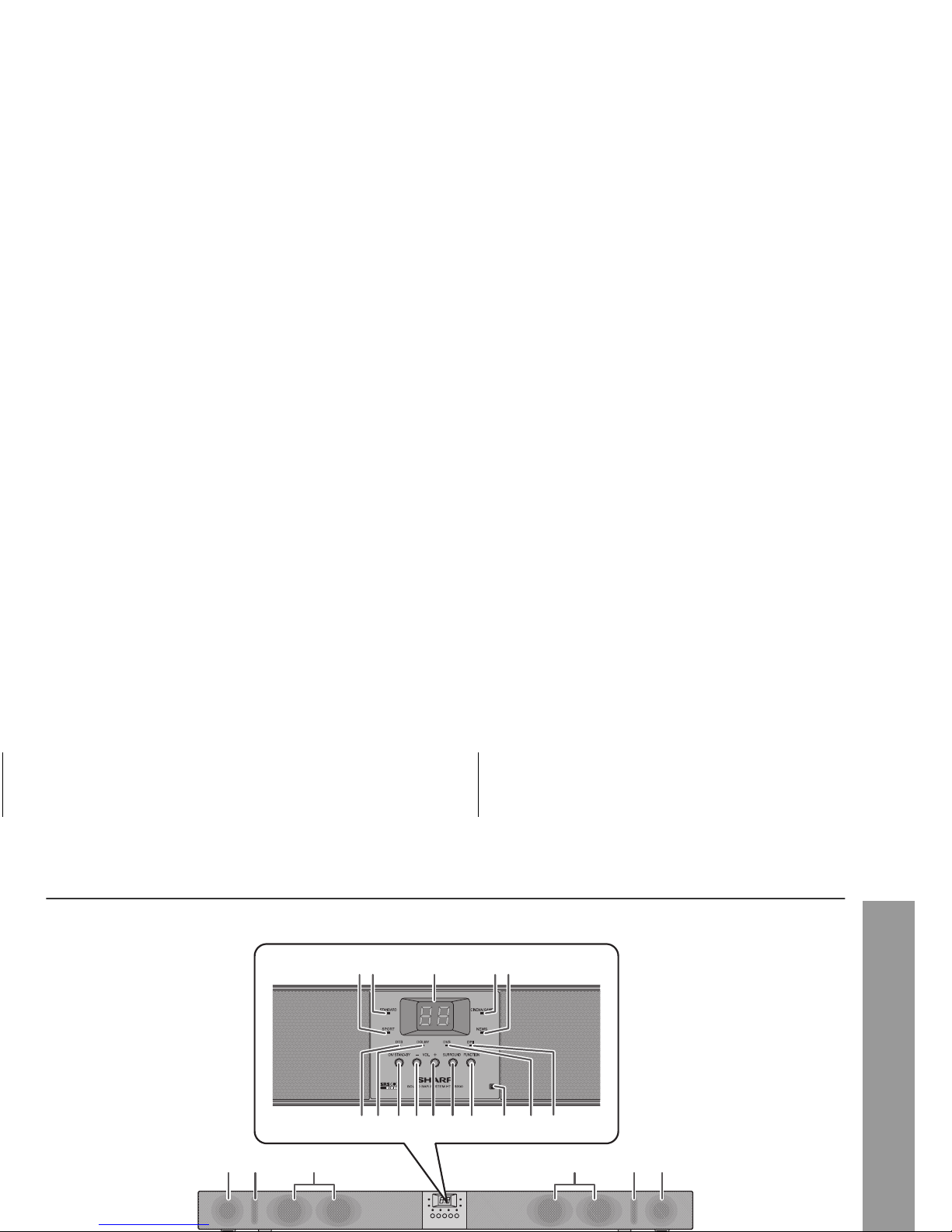
Controls and indicators
867 9 10 11 12 13 14 15
2 3
16 17 17 1918 18
451
Page 8
HT-SB300
Controls and indicators (continued)
LEFTRIGHT
LINE IN 1LINE IN 2
123 456
Page 9

HT-SB300
■
Remote Control
Reference page
1. Remote Control Transmitter . . . . . . . . . . . . . . . . . . 18
2. Dolby Virtual Speaker Button . . . . . . . . . . . . . . . . . 20
3. Cinema/Game Button. . . . . . . . . . . . . . . . . . . . . . . . 19
4. Standard Button . . . . . . . . . . . . . . . . . . . . . . . . . . . . 19
5. Volume Up Button . . . . . . . . . . . . . . . . . . . . . . . . . . 19
6. Subwoofer Level Down Button . . . . . . . . . . . . . . . . 21
7. Volume Down Button . . . . . . . . . . . . . . . . . . . . . . . . 19
8. Bass/Treble Button. . . . . . . . . . . . . . . . . . . . . . . . . . 21
9. TV Operation Buttons . . . . . . . . . . . . . . . . . . . . . . . . 9
10. On/Stand-by Button . . . . . . . . . . . . . . . . . . . . . . . . . 19
11. Sport Button . . . . . . . . . . . . . . . . . . . . . . . . . . . . . . . 19
12. News Button . . . . . . . . . . . . . . . . . . . . . . . . . . . . . . . 19
13. Subwoofer Level Up Button . . . . . . . . . . . . . . . . . . 21
14. Dimmer Button . . . . . . . . . . . . . . . . . . . . . . . . . . . . . 19
15. Mute Button . . . . . . . . . . . . . . . . . . . . . . . . . . . . . . . 19
16. Line Button . . . . . . . . . . . . . . . . . . . . . . . . . . . . . . . . 21
17. Digital 1 Button . . . . . . . . . . . . . . . . . . . . . . . . . . . . 21
18. Digital 2 Button . . . . . . . . . . . . . . . . . . . . . . . . . . . . 21
1
10
11
14
15
12
13
16
17
18
3
2
4
5
7
6
8
9
Page 10

HT-SB300
Speaker preparation
Select from three installation methods according to the
preferred position.
Note:
Option 1 or option 2 foot cushion positions based on LCD TV
Make sure to unplug the AC power cord before installing
the speaker or changing the position.
Option 2
Option 1
Using spikes
You may choose from the two different spike lengths provided:
25 mm and 30 mm.
Nuts (secured on 30 mm spikes) must be used when installing
either the 25 mm or 30 mm spikes.
The speaker can be leveled by adjusting the spikes and nuts.
Attach foot cushions as shown
Option 1
Option 2
Using foot cushions
Page 11

HT-SB300
Caution:
●
Be very careful to prevent the speaker [3.86 lbs. (1.75 kg)]
from falling when mounting on the wall.
●
Before mounting, check the wall strength. (Do not put on the
veneer plaster or whitewashed wall. The speaker may fall.) If
unsure, consult a qualified service technician.
●
Mounting screws are not supplied. Use appropriate ones.
●
Check all wall mount angle screws for looseness.
●
Select a good location. If not, accidents may occur or the
speaker may get damaged.
●
SHARP is not responsible for accidents resulting from
improper installation.
■
Driving screws
SHARP designed the speakers so you may hang them on the
wall. Use proper screws (not supplied). See below for size and
type.
■
Wall mount angle fixed to the wall
(Horizontal position)
To mount the speaker on the wall
1/8" (3.2 mm)
1
Fix the pattern paper to the wall in horizontal position
as below.
2
Make a hole on the wall following the screw point
marks on the pattern paper by using a drill.
29 mm
29 mm
44 mm
44 mm
509 mm
Pattern paper
Wall surface
3/8" (8-9 mm)
1-1/4" (32 mm)
Page 12

HT-SB300
Speaker preparation (continued)
■
Installing the speaker
4
Screw the wall mount angle to the wall as shown in the
illustration. (Total screw is 8 pieces)
Wall surface
Wall mount angle
Wall mount angle
Wall surface
Wall mount angle
(screws x 4)
(screws x 4)
1
Align the wall mount slot at the speaker to the wall
mount angle.
2
Slot the speaker into the wall mount angle.
3
Fix them securely.
Wall surface
Page 13

HT-SB300
Placing the speaker
Installation image:
Place the speaker as shown.
Notes:
●
As the sound from the speaker is omni-directional, you can
place the speaker anywhere you like. However, it is
recommended to place it as close to the TV as possible.
●
The front panel of the speaker is not removable.
■
Using other subwoofer
You can connect a subwoofer with an amplifier to the
SUBWOOFER PRE OUT jack.
TV
VCR
DVD player
Audio signal
Audio cable
(commercially
available)
Commercially available
subwoofer
(amplifier built in)
To audio input
jack
To SUBWOOFER PRE
OUT jack
Speaker
Page 14

HT-SB300
Falling prevention
Safety wires (not supplied) are useful to prevent the speaker
from falling off the table.
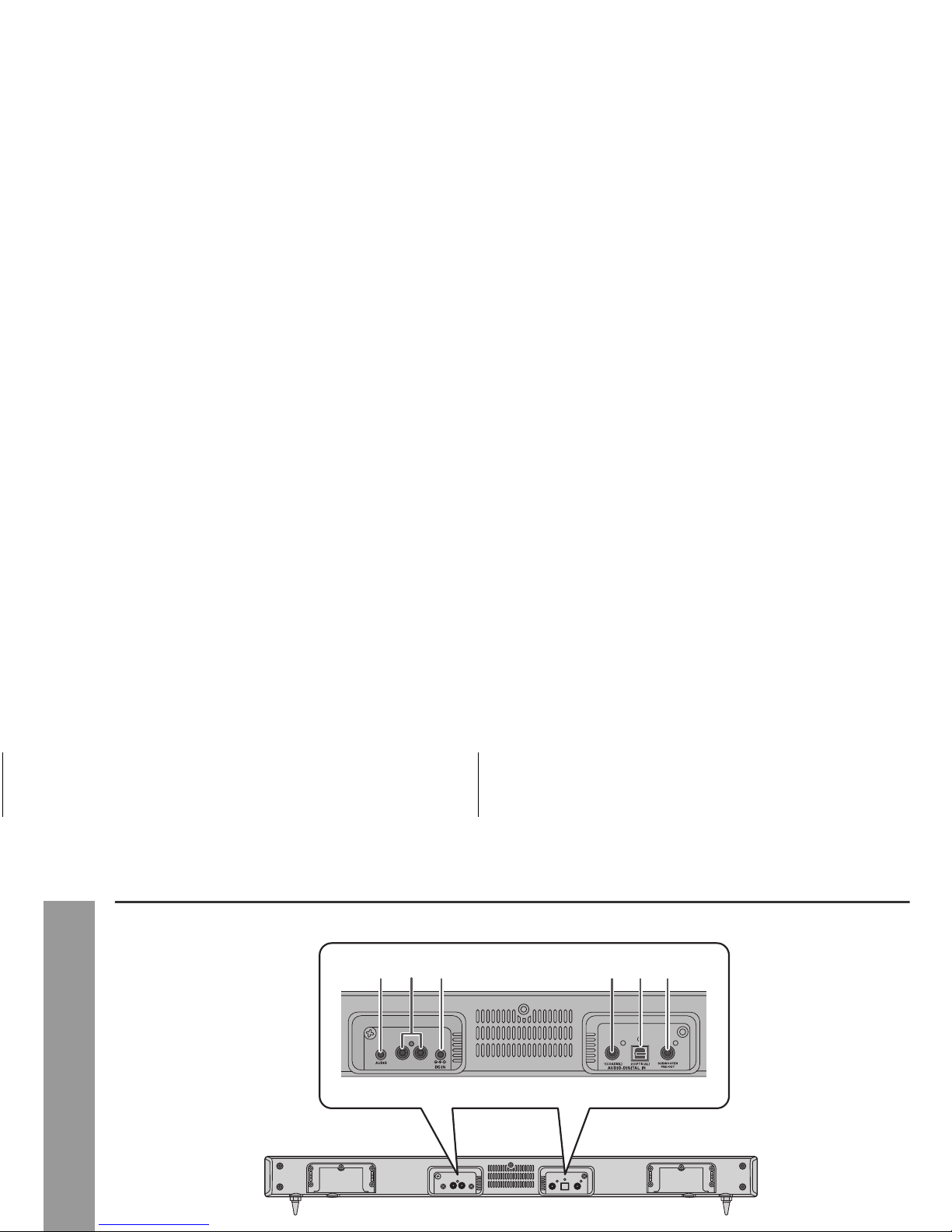
Speaker connections to TVs
Caution:
Turn off all other equipment before making any connections.
Tuner receiving for other audio system
●
Placing the antenna near the speaker AC power cord may
cause noise pick up. Place the antenna away from the
speaker for better reception.
Notes:
●
To connect to TV, use either LINE IN 1 jacks or AUDIO LINE
IN 2 jack only.
●
Refer the operation manual of the equipment to be
connected.
●
Fully insert the plugs to avoid fuzzy pictures or noises.
Page 15

HT-SB300
■
Connecting to a TV
If the TV/monitor has an audio output, connect it to the LINE IN
1 jacks on the rear of the speaker.
To select LINE IN 1 function:
●
On speaker: Press FUNCTION button repeatedly until “L1” is
displayed.
●
On remote control: Press LINE button repeatedly until “L1” is
displayed.
■
Connecting to a TV (with Headphone jack)
If the TV/monitor has headphone jack, connect it to the LINE IN
2 jack on the rear of the speaker.
To select LINE IN 2 function:
●
On speaker: Press FUNCTION button repeatedly until “L2” is
displayed.
●
On remote control: Press LINE button repeatedly until “L2” is
displayed.
To audio output jacks
RCA cable (supplied)
TV
HEADPHONE
To HEADPHONE jack
Audio cable (not supplied)
TV
Page 16

HT-SB300
Speaker connections to TVs (continued)
■
Connecting a digital tuner, etc.
Connect to the digital tuner, etc. using an optical digital audio
cable or a coaxial digital audio cable.
To select DIGITAL 1 (coaxial input) or DIGITAL 2 (optical
input) function:
●
On speaker: Press FUNCTION button repeatedly until “d1” or
“d2” is displayed.
●
On remote control: Press DIGITAL 1 or DIGITAL 2 button and
“d1” or “d2” is displayed.
Coaxial digital audio cable
(commercially available)
Optical digital
audio cable
(commercially
available)
To COAXIAL
input jack
To the TV (video)
To OPTICAL
input jack
Speaker
To coaxial digital audio output jack
Audio signal
Audio signal
To optical
digital audio
output jack
Page 17

HT-SB300
AC power connection
After checking all the connections have been made correctly,
connect the AC power cord to the AC power input jack, then to
the AC outlet.
■
Using with the AC/DC adaptor
Notes:
●
Unplug the AC/DC adaptor from the AC outlet if the speaker
will not be used for a prolonged period of time.
●
Use only the supplied AC/DC adaptor. Using other AC/DC
adaptor may cause an electric shock or fire.
1
Plug the AC power cord into the AC/DC adaptor.
2
Plug the AC/DC adaptor cable into the DC IN jack on
the speaker.
3
Plug the AC power cord into an AC outlet. The STANDBY indicator will turn RED when AC power is applied.
The power indicator will turn GREEN when the system
in “ON”.
RIGHT LEFT
LINE IN 1LINE IN 2
2
1
3
AC/DC Adaptor Cable
DC IN jack
(DC 12 V)
AC/DC Adaptor
AC Outlet
(AC 100 - 240 V ~ 50/60 Hz)
AC power cord
Page 18

HT-SB300
Remote control
■
Battery installation
This product contains a CR Coin Lithium Battery which contains
Perchlorate Material – special handling may apply, California
residents, see www
.dtsc.ca.gov/hazardouswaste/perchlorate/
Caution:
●
Do not use rechargeable battery (nickel-cadmium battery,
etc.).
●
Danger of explosion if battery is incorrectly replaced.
●
Replace only with the same or equivalent type.
●
Batteries (battery pack or batteries installed) shall not be
exposed to excessive heat such as sunshine, fire or the like.
●
Installing the battery incorrectly may cause the speaker to
malfunction.
Notes concerning use:
●
Replace the battery if the operating distance is reduced or if
the operation becomes erratic. Purchase “CR 2025”, coin
lithium battery.
●
Periodically clean the transmitter on the remote control and
the sensor on the speaker with a soft cloth.
●
Exposing the sensor on the speaker to strong light may
interfere with operation. Change the lighting or the direction
of the speaker if this occurs.
●
Keep the remote control away from moisture, heat, shock,
and vibrations.
■
Test of the remote control
Point the remote control directly at the remote sensor on the
1
Insert pin into the hole as shown and pull to open the
battery holder.
2
Remove the old battery from the battery holder, insert
the new battery and then slide the battery holder back
into the remote control.
Back of
remote control
Pin
Battery holder
Page 19

HT-SB300
General control
■
To turn the power on
Press the ON/STAND-BY button.
●
The power indicator turns green. If the power does not turn
on, check whether the power cord is plugged in properly.
To set the speaker to stand-by mode:
●
Press the ON/STAND-BY button again.
■
Volume control
Remote control operation:
Press the VOLUME + button to increase the volume and the
VOLUME – button to decrease the volume.
■
Preset sound mode
Main unit operation:
When the SURROUND button is pressed, the current mode
setting will light up. To change to a different mode, press the
SURROUND button repeatedly until the desired sound mode
lights up.
Speaker operation:
Press volume up (VOL. +) to increase
the volume and press volume down
(VOL. – ) to decrease the volume.
■
Muting
The volume is muted temporarily when pressing
the MUTE button on the remote control. Press
again to restore the volume.
00 01 02 ..... 59 60
Page 20

HT-SB300
General control (continued)
■
Dolby Virtual Speaker (DVS) sound mode
The Dolby Virtual Speaker (DVS) creates virtual surrounds
comparable to the 5.1ch sound produced by the 2.1ch speaker.
When setting DVS to “ON” for 2 channel stereo signals, Dolby
Pro Logic II brings out virtual sound effects through the signals
converted into 5.1ch.
Press the DVS button.
The Dolby Virtual Speaker indicator lights up.
Notes:
●
Monaural signals do not generate surround effects.
●
DVS sound effect may not be obtained depending on signal
types (the Dolby Virtual Speaker indicator blinks). In this
case, set the DVS mode to “OFF”.
●
DVS can only be turned on using remote control.
●
If you turn ON DVS, WOW HD will automatically turn OFF.
●
The DVS can be turned OFF by pressing any of the preset
sound mode buttons.
This product incorporates decoders supporting the Dolby Digital
system and DTS system.
The Dolby Virtual Speaker creates multichannel-like
sound effects.
Compared with the cinema mode, the bass sound
level is slightly reduced.
The Dolby Pro Logic II indicator also lights up if 2ch
sound signals are detected.
ON
Page 21

Page 22

HT-SB300
Troubleshooting chart
Many potential problems can be resolved by the owner without calling
a service technician.
If something is wrong with this product, check the following before
calling your authorized SHARP dealer or service center.
■
General
■
Condensation
Sudden temperature changes, storage or operation in an extremely
humid environment may cause condensation inside the cabinet or on
the transmitter on the remote control.
Condensation can cause the speaker to malfunction. If this happens,
leave the power on until normal operation is possible (about 1 hour).
Wipe off any condensation on the transmitter with a soft cloth before
operating the speaker.
■
If problem occurs
When this product is subjected to strong external interference
(mechanical shock, excessive static electricity, abnormal supply voltage
due to lightning, etc.) or if it is operated incorrectly, it may malfunction.
If such a problem occurs, do the following:
Symptom Possible cause
No sound is heard.
●
Is the input signal (selection) set
properly?
●
Is the volume level set to “0”?
●
Is muting activated?
Noise is heard during
playback.
●
Move the speaker away from any
computers or mobile phones.
When a button is
pressed, the speaker
does not respond.
●
Set this speaker to the stand-by mode
and then turn it back on.
The power is not turned
on.
●
Is the speaker unplugged? (Refer to
page 17)
●
The protection circuit may be
Symptom Possible cause
The speaker cannot be
turned on with the
remote control.
●
Is the AC power cord of the speaker
plugged in?
●
Is the battery inserted?
TV cannot be operated
with the remote control.
●
Depending on the model, some or all
functions may not be operable using the
remote control of this speaker. In this
case, use the remote control supplied
with the TV.
Page 23

Page 24

CONSUMER LIMITED WARRANTY
SHARP ELECTRONICS CORPORATION warrants to the first consumer purchaser that this Sharp brand product (the “Product”), when shipped in its original container, will be free from defective workmanship and materials, and agrees that it will, at its option, either repair the defect or replace the defective Product or part thereof
with a new or remanufactured equivalent at no charge to the purchaser for parts or labor for the period(s) set forth below.
This warranty does not apply to any appearance items of the Product nor to the additional excluded item(s) set forth below nor
to any Product the exterior of which has
been damaged or defaced, which has been subjected to improper voltage or other misuse, abnormal service or handling, or which has been altered or modified in
design or construction.
In order to enforce the rights under this limited warranty, the purchaser should follow the steps set forth below and provide proof of purchase to the servicer.
The limited warranty described herein is in addition to whatever implied warranties may be granted to purchasers by law. ALL IM
PLIED WARRANTIES INCLUDING
THE WARRANTIES OF MERCHANTABILITY AND FITNESS FOR USE ARE LIMITED TO THE PERIOD(S) FROM THE DATE OF PURCHASE SET FORTH BELOW
.
Some states do not allow limitations on how long an implied warranty lasts, so the above limitation may not apply to you.
Neither the sales personnel of the seller nor any other person is authorized to make any warranties other than those described
herein, or to extend the duration of any
warranties beyond the time period described herein on behalf of Sharp.
The warranties described herein shall be the sole and exclusive warranties granted by Sharp and shall be the sole and exclusive
remedy available to the purchaser.
Correction of defects, in the manner and for the period of time described herein, shall constitute complete fulfillment of all liabilities and responsibilities of Sharp to the
purchaser with respect to the Product, and shall constitute full satisfaction of all claims, whether based on contract, negligence, strict liability or otherwise. In no event
shall Sharp be liable, or in any way responsible, for any damages or defects in the Product which were caused by repairs or attempted repairs performed by anyone
other than an authorized servicer. Nor shall Sharp be liable or in any way responsible for any incidental or consequential economic or property damage. Some states
do not allow the exclusion of incidental or consequential damages, so the above exclusion may not apply to you.
THIS WARRANTY GIVES YOU SPECIFIC LEGAL RIGHTS. YOU MAY ALSO HAVE OTHER RIGHTS WHICH VARY FROM STATE TO STATE.
Model Specific Section
Y
our Product Model Number & Description:
(Be sure to have this information available when you need service for your Product.)
Warranty Period for this Product: One (1) year parts and labor from the date of purchase.
HT-SB300 Sound Bar System
 Loading...