

Page 1
CVP09FX
SERVICE MANUAL
S3503CVP09FX/T
PORTABLE AIR CONDITIONER
CONTENTS
CHAPTER 1. PRODUCT SPECIFICATION
[1] SPECIFICATION............................................1-1
[2] ELECTRICAL PARTS .................................... 1-1
[3] WIRING DIAGRAM........................................1-2
[4] EXTERNAL DIMENSION...............................1-2
CHAPTER 2. OPERATION INSTRUCTION
[1] PART NAMES................................................2-1
[2] LOCATION.....................................................2-2
[3] INCLUDED.....................................................2-3
[4] INSTALL WINDOW PANEL ........................... 2-3
[5] INSTALLATION AND REMOVAL OF EX-
HAUST HOSE................................................2-4
[6] PRE-OPERATION CHECKS..........................2-5
[7] OPERATION MODE ...................................... 2-5
[8] DRAINAGE ....................................................2-7
[9] MAINTENANCE.............................................2-7
MODEL
In the interests of user-safety (Required by safety regulations in some countries)
the set should be restored to its original condition and only parts identical to
those specified should be used.
CHAPTER 4. EXPLANATION OF CIRCUIT AND OPERATION
[1] ELECTRONIC CONTROL CIRCUIT DIA-
GRAM............................................................4-1
[2] PRINTED WIRING BOARD...........................4-2
[3] FUNCTION....................................................4-3
[4] PERFORMANCE CURVES...........................4-6
CHAPTER 5. ATTENTION WHEN REPAIRING
[1] HOW TO REPAIR REFRIGERATION ...........5-1
[2] ELECTRICAL COMPONENT TEST..............5-3
CHAPTER 6. TROUBLESHOOTING GUIDE
[1] TROUBLESHOOTING ..................................6-1
REPLACEMENT P ARTS LIST
CV-P09FX
CHAPTER 3. DISASSEMBLING PROCEDURE
[1] PROCEDURE FOR DISASSEMBLY ............. 3-1
[2] DISASSEMBLING THE CONTROL BOX........3-9
Parts marked with " " are important for maintaining the safety of the set. Be sure to replace these parts with specified ones for
maintaining the safety and performance of the set.
SHARP CORPORATION
This document has been published to be used
for after sales service only.
The contents are subject to change without notice.
Page 2
CVP09FX
CVP09FX
CHAPTER 1. PRODUCT SPECIFICATION
ServiceManual
[1] SPECIFICATION
Cooling Capacity BTU/h 9000
Moisture Removal Pint/h 2.5
Electrical Data
Phase Single
Rated frequency Hz 60
Rated voltage V 115
Rated current A 9.0
Rated input W 1010
Power factor % 98
EER BTU/Wh 8.9
Compressor
Type (Hermetically sealed rotary type)
Model, Motor Output 44R211AE-AJS (805W)
REFRIGERANT SYSTEM
Evaporator Louver fin, Grooved tube, 7mm, hair pin
Condenser Louver fin, Grooved tube, 7mm, hair pin
Control O.D. x I.D x Length(mm)
(Capillary Tube)
Refrigerant Volume R-22 (OZ)
(Factory Charge)
NET DIMENSIONS
Width Height Depth Inch (mm) 18.5" (470) x 32.3" (820) x 15.1" (383)
Net Weight Lbs 84
GROSS DIMENSIONS
Width Height Depth Inch (mm) 22.1" (561) x 35.8" (910) x 18.3" (465)
Gross Weight Lbs 95
FAN SYSTEM
Indoor side (Evaporator) Centrifugal fan
Outdoor side (Condenser) Centrifugal fan
Air Flow rate (Indoor side) CFM High / Med / Low
OTHERS
Safety devices Compressor : Overload relay
Air filter Polypropylene net
Power cord length ft 4.6
Power plug type NEMA 5-15P
2.7 x 1.4 x 400
12.5
240/190/140
Fan motor (IN/OUT) : Internal thermal fuse / Internal thermal protector
[2] ELECTRICAL PARTS
Running capacitor 250V - 60µF
Fan capacitor (IN/OUT) 250V - 6µF / 250V - 8µF
Thermistor 10kΩ at 77°F (TH1), 4.431kΩ at 77°F (TH2, TH3)
Fan motor (IN) IBH-884-512 (MLB180)
Fan motor (OUT) PFU040ZREA/SHP (MLB178)
Overload relay MRA99239L-9054 or B380-150B-141E
Drain motor ORM-1524K1 (M-A438)
1 – 1
Page 3
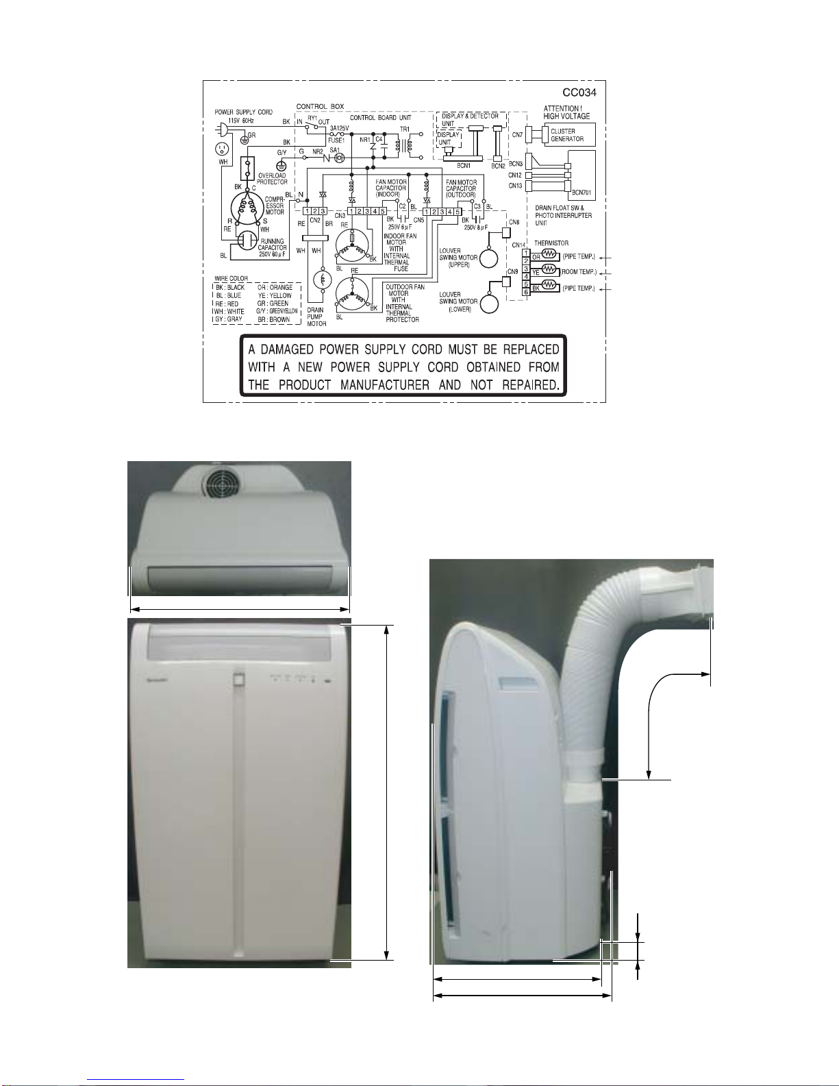
[3] WIRING DIAGRAM
CVP09FX
[4] EXTERNAL DIMENSION
18.5"
M
M
TH2
TH1
TH3
Max. : 59"
32.3"
0.95"
15.1"
16.1"
1 – 2
Page 4
CVP09FX
CVP09FX
CHAPTER 2. OPERATION INSTRUCTION
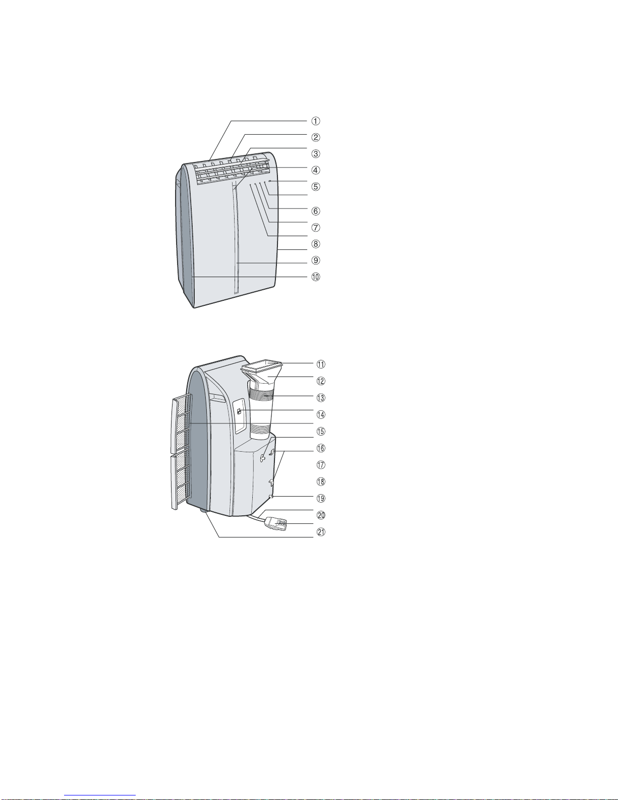
[1] PART NAMES
1. Front view
ServiceManual
Air Outlet
Vertical louvers
Horizontal louvers
PLASMACLUSTER Lamp (blue)
Remote control signal receiver
window
AUX. Button
OPERATION Lamp (red)
TIMER Lamp (orange)
MEGA COOL Lamp (green)
Air inlet
2. Rear view
Exhaust air outlet
Window exhaust adapter
Exhaust hose
Remote control hook
Air filters
Drainage nozzle and stopcock
Power supply cord hooks
Drainpipe nozzle and stopcock
Power supply cord
Power plug
Casters(4)
2 – 1
Page 5
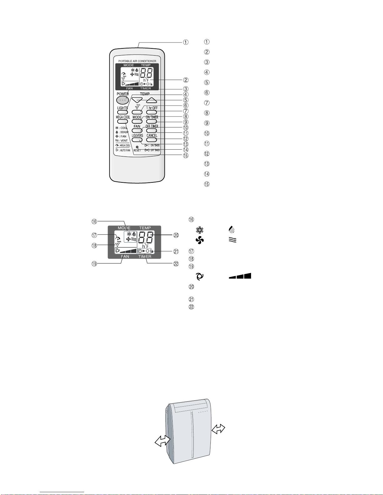
3. Remote control
CVP09FX
Transmitter
Display
POWER Button
LIGHTS Button
TEMPERATURE Button
PLASMACLUSTER Button
1 hr OFF Button
MODE Button
ON TIMER Button
FAN Button
OFF TIMER Button
CANCEL Button
LOUVERS Button
RESET Button
MEGA COOL Button
4. Remote control display
MODE SYMBOLS
: COOL : DEHUMIDIFICATION
: FAN : VENTILATION
MEGA COOL SYMBOL
PLASMACLUSTER SYMBOL
FAN SPEED SYMBOLS
: AUTO : Manual setting
TEMPERATURE AND TIMER COUNT
DOWN INDICATOR
TRANSMITTING SYMBOL
ON TIMER / OFF TIMER SYMBOL
[2] LOCATION
• The air conditioner should be placed on a firm foundation to minimize noise and vibration. For safe and secure positioning, place the unit on a
smooth, level floor strong enough to support the unit.
• The unit has casters to aid placement, but it should only be rolled on smooth, flat surfaces. Use caution when rolling on carpet surfaces. Do not
attempt to roll the unit over objects.
• The unit must be placed within reach of a properly rated grounded socket.
• Never place any obstacles around the air inlet or outlet of the unit.
• Allow at least 12" (30cm) of space from the wall for efficient air-conditioning.
MIN.12"
(30cm)
MIN.12"
(30cm)
2 – 2
Page 6
CVP09FX
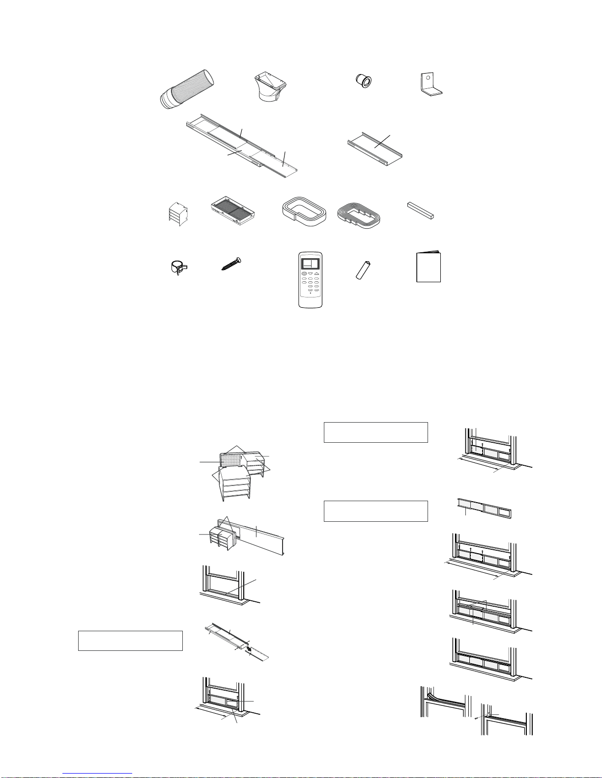
[3] INCLUDED
Exhaust hose (1) Window exhaust adapter (1)
Exhaust cover (1)
Drainage Grommet (1)
Extension panel (1)
Bracket (1)
Adjustment panel (1)
Window panel (1)
Rain guard (2)
Insect guard net (1)
Foam seal (1)
Foam seal (3)
(adhesive type)A
Foam seal (1)
(adhesive type)B
(thickness:1/5") (thickness:2/5")
Hose clamp (1)
Screw (8)
Remote control (1)
Battery (2)
(AAA.R03)
Manual (1)
SUGGESTED TOOLS FOR WINDOW PANEL INSTALLATION
1. Screwdriver(medium size Phillips)
2. Tape measure or ruler
3. Knife or scissors
4. Saw (In the event that the window panel needs to be cut down in size because thewindow is too narrow for direct installation.)
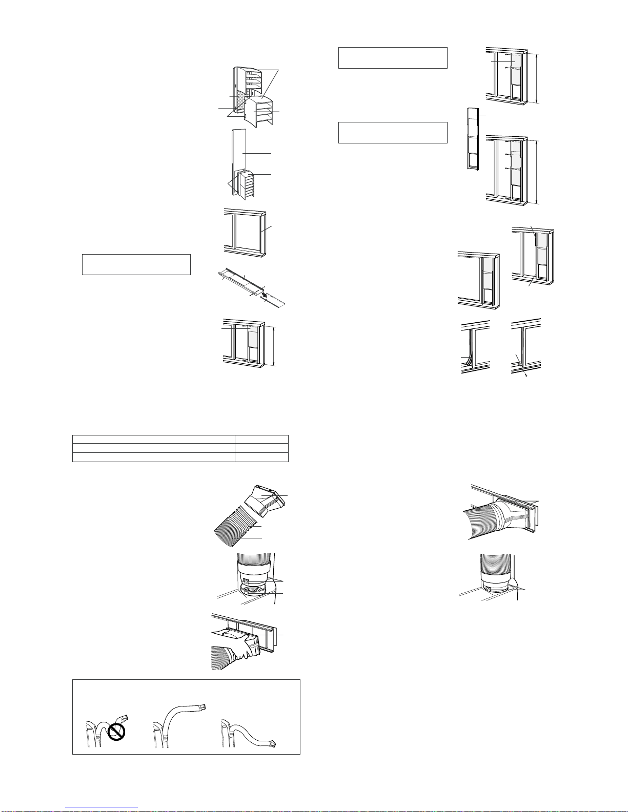
[4] INSTALL WINDOW PANEL
Installation in a double-hung sash window
(See page 14 for installation in a sliding sash window. )
Connect the rain guards to the insect
1
guard net.
Insert all three projections on each rain
guard into the holes in the insect guard net.
Side “A” will now be uppermost, as indicated in the diagram.
Attach the guard combined above to the
2
window panel
Push the insect guard net firmly to ensure
that its four projections fit into the holes in
the window panel.
Side “A” will now be at the top, as indicated
in the diagram.
Cut the foam seal A (adhesive type) to
3
the proper length and attach it to the
window stool.
Attach the window panel to the window
4
stool.
If the inner width of the window is between 22" (559mm) and 24" (609mm)
inclusive.
The window panel cannot be installed in
windows less than 22" (559mm) wide, as
you will be unable to shut the exhaust cover.
(1) Remove the adjustment panel from th e
window panel, and cut the window
panel to the same width as the window.
(2) Open thewindow sash and place the win-
dow panel on the window stool
(3) Secure the window panel to the window
stool with 2 screws.
Insect guard
net
Projection
"A"
Window
panel
22"~ 24"
Hole
Projection
Exhaust cover
Adjustment panel
Window stool
Window panel
Foam seal A
(adhesive type)
Cut
Window panel
Rain guard
"A"
If the inner width of the window is
between 24" (609mm) and 36.8"
(934mm) inclusive.
(1) Open the window sash and place the
window panel on the window stool.
(2) Slide the adjustment panel to fit the
window frame width.
(3) Secure the window panel tothe stool with
3 screws.
If the inner width of the window is
between 36.8" (934mm) and 48"
(1219mm) inclusive.
(1) Attach the extension panel to the
adjustment panel.
(2) Open thewindow sash and place the win-
dow panel on the window stool.
(3) Slide the adjustment and extension
panels to fit the window frame width.
(4) Secure the window panel to the window
stool with 4 screws.
Cut the foam seals (adhesive type) A and
5
B to the proper length and attach it to the
window panel.
Attach foam seal A to the window panel and
extension panel, and attach foam seal B to
the adjustment panel.
Close the window sash securely against
6
the Window panel.
Cut the foamseal to an appropriate length
7
and seal the opening between the top of
the inner window sash and the outer window sash.
Attach a bracket with the screw.
8
36.8"~48"
Foam seal
24"~36.8"
Extension panel
Foam seal B
(adhesive type)
Adjustment panel
Foam seal A
(adhesive type)
Bracket
2 – 3
Page 7
CVP09FX
Installation in a sliding sash window
(See page 12 for installation in a double-hung window.)
Connect the rain guards to the insect
1
guard net.
Insert all three projections on each rain
guard into the holes in the insect guard net.
Side “A” will now be uppermost, as
indicated in the diagram.
Attach the guard combined above to the
2
window panel.
Push the insect guard net firmly to ensure
that its four projections fit into the holes in
the window panel.
Side “A” will now be at the top, as indicated
in the diagram, when it is installed in the
window.
Cut the foam seal A (adhesive type) to the
3
proper length and attach it to the window
frame.
Install the window panel into the window
4
frame.
If the inner height of the window is
between 22" (559mm) and 24" (609mm)
inclusive.
The window panel cannot be installed in
windows less than 22" (559mm) high, as
you will be unable to shut the exhaust
cover.
(1) Remove the adjustment panel from the
window panel, andcut the window panel
to the same height as the window.
(2) Open the window sash and place the
window panel on the window frame.
(3) Secure the window panel to the window
frame with 2 screws.
Insect guard net
Hole
Projection
Projection
Window
panel
Window
panel
Exhaust cover
Adjustment panel
"A"
Rain guard
Window panel
"A"
Foam seal A
(adhesive type)
Cut
22"~24"
If the inner height of the window is
between 24" (609mm) and 36.8"
(934mm) inclusive.
(1) Open the window sash and place the
window panel on the window frame.
(2) Slide the adjustment panel to fit the
window frame height.
(3) Secure the window panel to the window
frame with 3 screws.
If the inner height of the window is between 36.8" (934mm) and 48" (1219mm)
inclusive.
(1) Attach the extension panel to the
adjustment panel.
(2) Open the window sash and place the
window panel on the window frame.
(3) Slide the adjustment and extension
panels to fit the window frame height.
(4) Secure the window panel to the window
frame with 4 screws.
Cut the foam seals (adhesibe type) A and
5
B to the proper length and attach them to
the window panel.
Attach foam seal Ato the window panel and
extension panel, and attach foam seal B to
the adjustment panel.
Close the window sash securely against
6
the Window panel.
Cut the foamseal to an appropriate length
7
and seal the opening between the side of
the inner window sash and the outer window sash.
Attach a bracket with the screw.
8
Foam seal
Adjustment
panel
Extension panel
Foam seal B
(adhesive type)
Foam seal A
(adhesive type)
Bracket
24"~36.8"
36.8"~48"
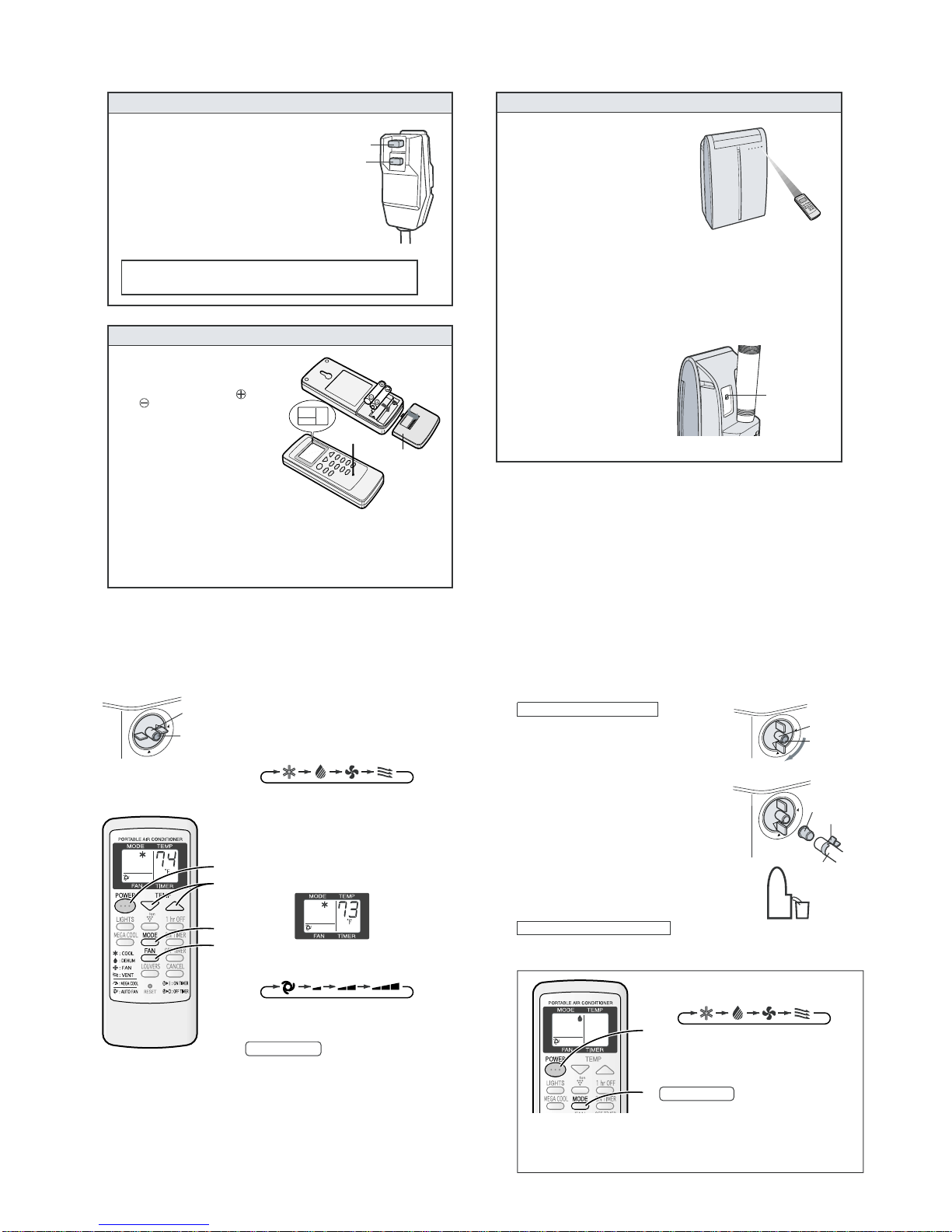
[5] INSTALLATION AND REMOVAL OF EXHAUST HOSE
The exhaust hose must be installed or removed in accordance with the usage mode.
MODE EXHAUST HOSE
COOL, FAN, VENTILATION, DEHUMIDIFICATION with no container Install
DEHUMIDIFICATION with container(minimum capacity 3 gallons) Remove
Installation of the exhaust hose
Attach the window exhaust adapter to
1
the exhaust hose.
Extend one end of the exhaust hose and
insert it into the window exhaust adapter,
and turn it (approx. three times) until it
stops.
Make sure they are securely attached
afterwards.
Attach the exhaust hose adapter to the
2
unit.
Insert the two projections on the exhaust
hose adapter into the two holes on the
unit, and firmly attach them to each
other.
Slide and open the exhaust cover on
3
the window panel, and attach the window exhaust adapter.
Surface of window exhaust adapter
marked "TOP" should be at the top when
it is installed in a double-hung sash
window.
Surface of window exhaust adapter
marked "TOP" should be on the window
frame side when it is installed in a sliding
sash window.
The exhaust hose should be as short as possible for operational efficiency;
however, it must not be twisted or bent.
Unacceptable
Acceptable
Acceptable
Extend
Exhaust hose
Window
exhaust
adapter
Projection
Hole
"TOP"
Removal of the exhaust hose
Remove the window exhaust adapter.
1
Pull out and remove the window exhaust
adapter by pushing down two “PUSH”
markings, and slide and close the exhaust
cover in the window panel.
Remove the exhaust hose adapter from
2
the unit.
Lift up and remove the exhaust hose
adapter from the unit by pushing down on
the two projections.
"PUSH"
Projection
2 – 4
Page 8
CVP09FX
1
Remove the exhaust hose (See Page 17)
2
Turn the drainage nozzle to the OPEN position.
3
Pull the stopcock out from the drainage nozzle.
• When the stopcock is removed, a small amount of water
may be discharged from the drainage nozzle.
• Always perform this procedure with the unit turned off.
Drain water will spout out if attempted during operation.
4
I
nsert the hose clamp into a standard commercially-available hose (5/8"inner diameter, 7/8" outer
diameter) and attach the drain grommet to the
hose.
5
Attach the hose to the drainage nozzle, and secure
it with the hose clamp.
• Insert the hose securely into a container with a minimum
capacity of 3 gallons. Be sure to monitor the water levelin
the container and empty as necessary. Do not operate in
dehumidify mode for more than 8 hours at a time. Be sure
to empty the watercontainer wheneverdehumidify modeis
started. Failure to empty the water container can cause
the container to overflow and cause damage to underlying
materials.
• Set the hose sloping downwards for easier drainage.
Moreover, do not bend the hose at any point, nor allow
the end to be submerged in water.
Dehumidification with no container
2
1
In this mode, the air conditioner dehumidifies the room.
CAUTION
When operating dehumidification with container, the unitgenerates heat during dehumidification mode and the room temperature will rise. Operate dehumidification with no container if
you don't want the room temperature to rise. This will help to slightly drop the room
temperature, but dehumidification performance will become less effective than when operating dehumidification with container.
1
Press the MODE button to select DEHUMIDIFICATION mode.
COOL DEHUM FAN VENT
2
Press the power button to start operation.
• The red OPERATION lamp on the unit will light.
• The temperature cannot be set.
• The fan speed is preset to AUTO and cannot be
changed.
TO TURN OFF
Press the POWER button again.
• The red OPERATION lamp on the unit will turn off.
Dehumidification with container
Drainage nozzle
Stopcock
Drain grommet
Hose clamp
Hose
I
f draining of the water is not desirable, install the exhaust hose (See Page 16), turn the drainage nozzle to the
CLOSE position, and check that the drainage nozzle is covered with the stopcock. In this operation, the water
tank inside the unit may be full, the unit stops operating and then the TIMER, OPERATION and MEGA COOL
lamps are blinking, depending on room condition. In this case, drain out the water within the unit (See Page 29).
"OPEN" position
[6] PRE-OPERATION CHECKS
POWER PLUG CHECK
This air conditioner uses a fused power plug.
Always check the power plug before use.
Press the RESET button.
1
Insert the power plug into the wall socket.
2
Press the TEST button.
3
You will hear a CLICK if the circuit breaker is
functioning correctly.
Press the RESET button until you hear another
4
CLICK.
The circuit breaker is activated, power is supplied,
and the air conditioner is now ready for use.
Do not attempt to use the air conditioner if the above procedure is
impossible, as it is malfunctioning.
Disconnect the power plug and request service.
LOADING BATTERIES
Remove the battery cover at the
1
back of the remote control.
Insert batteries into the compart-
2
ment, making sure the
polarities are correctly
aligned.
¥ Lines will appear on the display
when batteries are properly installed.
Reattach the battery cover.
3
Press the RESET button using a
4
thin pointed implement.
NOTES:
¥ The battery should last approximately one year under normal use.
¥ When replacing the batteries, always change both batteries at the same time, and
make sure they are the same type.
¥ If the remote control does not operate normally after replacing the batteries, press
the RESET button using a thin pointed implement.
¥ If you will not be using the unit for a prolonged period, remove the batteries from
the remote control.
Use two AAA (R03) batteries.
and
RESET
TEST
Battery cover
HOW TO USE THE REMOTE CONTROL
Point the remote control towardsthe
units signal receiver window and
press the desired button. A beep
will sound when the unit receives
the signal.
• Make sure nothing, such as curtains,
blocks the signal receiver window.
• The remote control operates up to 23
feet (7 meters) away.
CAUTION
• Do not expose the signal receiver window to direct sunlight. This may adversely
affect its operation. If necessary, close the curtains to block out the sunlight.
• Use of a fluorescent lamp in the same room may interfere with transmission of the
signal.
• The unit may be affected by signals emitted from other remote controllers for
televisions, VCRs or other equipment used in the same room.
• Do not leave the remote control exposed to direct sunlight or near a heater. Protect the remote control from moisture and shock which can discolor or damage it.
To prevent the remote control from
being misplaced, hook it to the unit
when not in use.
When attached, to remove the remote
control from the unit, lift the remote
control up slightly and pull it out.
Remote control hook
[7] OPERATION MODE
1. Cool mode 2. Dehumidification mode
Install the exhaust hose (See Page16), turn
the drainage nozzle to the CLOSE position,
Drainage nozzle
"CLOSE" position
Stopcock
and check the drainage nozzle is covered
with the stopcock.
Press the MODE button to select COOL
1
mode.
COOL DEHUM FAN VENT
Press the POWER button to start op-
2
eration.
• The red OPERATION lamp on the unit will
light.
Press the TEMPERATURE button toset
3
2
3
the desired temperature.
• The temperature can be setwithin the range
of 64°F to 86°F.
1
4
Press the FAN button to set the de-
4
sired fan speed.
AUTO QUIET LOW HIGH
TO TURN OFF
Press the POWER button again.
• The red OPERATION lamp on the unit will turn
off.
2 – 5
Page 9
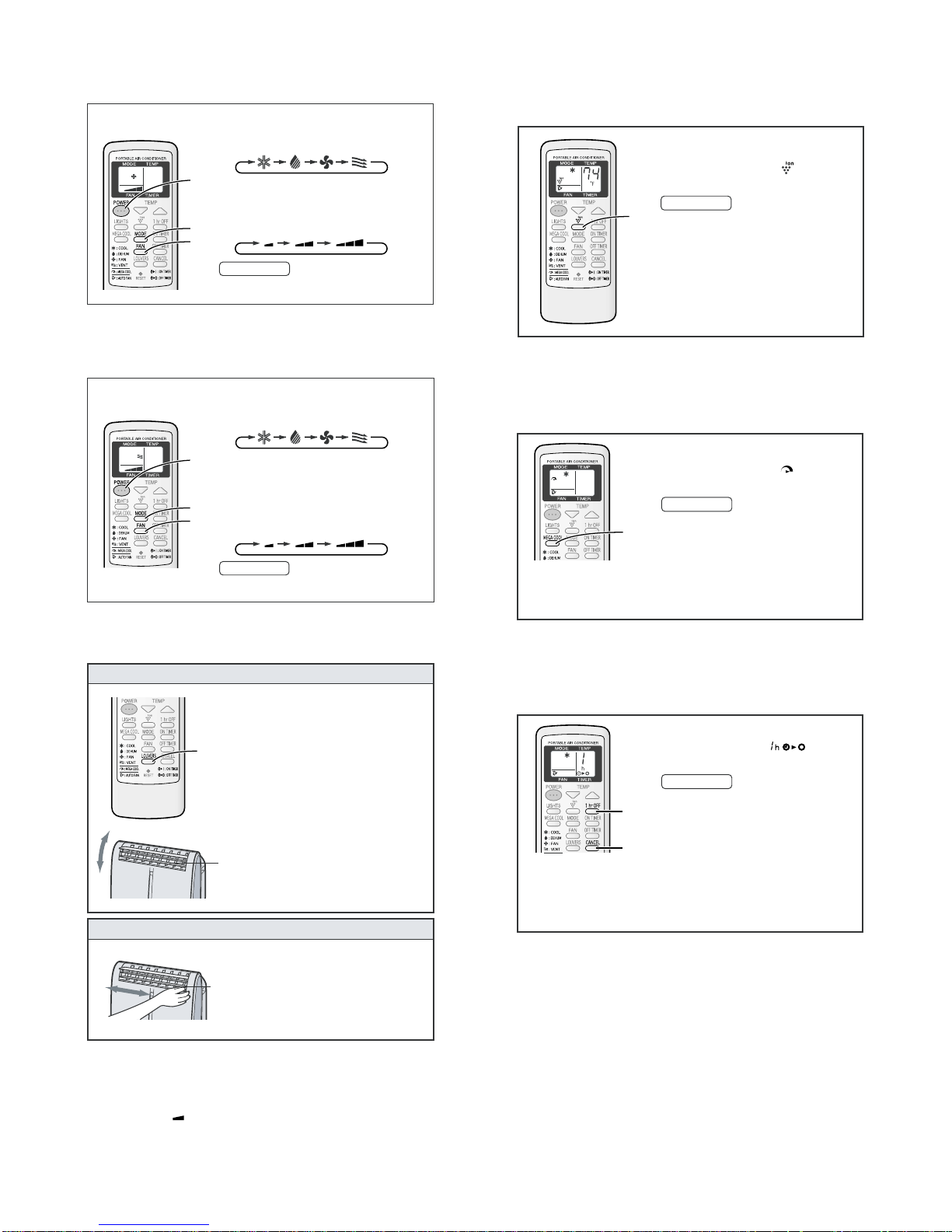
3. Fan mode
1
Press the PLASMACLUSTER button during
operation.
• The remote control will display “ ”.
• The blue PLASMACLUSTER lamp on the unit will
light.
TO CANCEL
Press the PLASMACLUSTER button again.
• The PLASMACLUSTER lamp on the unit will turn off.
NOTES:
• Use ofthe PLASMACLUSTER function will bememorized and it will be activated the next time you turn on
the air conditioner.
• To turn off the PLASMACLUSTER Lamp, press the
LIGHTS button.
• PLASMACLUSTER operation cannot be set during
VENTILATION mode.
The Plasmacluster ion generator inside the air conditioner will release positive and
negative Plasmacluster ions into the room. Approximately the same numbers of positive and negative ions released into the air.
1
In this mode, the air conditioner simply circulates the air without cooling it.
Install the exhaust hose (See Page16), turn the drainage nozzle to the CLOSE
position, and check the drainage nozzle is covered with the stopcock.
Press the MODE button to select FAN mode.
1
COOL DEHUM FAN VENT
2
Press the POWER button to start operation.
2
• The red OPERATION lamp on the unit will light.
2
5
• The temperature cannot be set.
Press the FAN button to set the desired fan
3
3
speed.
1
3
1
QUIET LOW HIGH
TO TURN OFF
Press the POWER button again.
• The red OPERATION lamp on the unit will turn off.
4. Ventilation mode
CVP09FX
6. Plasmacluster operation
In this mode, the air conditioner ventilates the air to outdoors.
Install the exhaust hose (See Page 16), turn the drainage nozzle to the CLOSE
position, and check the drainage nozzle is covered with the stopcock.
Press the MODE button to select VENT mode.
1
COOL DEHUM FAN VENT
Press the POWER button to start operation.
2
2
2
• The red OPERATION lamp on the unit will light.
• The temperature cannot be set.
5
Press the FAN button to set the desired fan
3
3
speed.
• Although the louvers are closed and no air blows
1
3
out into the room, the external ventilation fan speed
changes.
1
4
QUIET LOW HIGH
TO TURN OFF
Press the POWER button again.
• The red OPERATION lamp on the unit will turn off.
5. To change air flow direction
UP / DOWN AIR FLOW DIRECTION
Press the LOUVERS button on the re-
1
mote control.
• The horizontal louvers will swingcontinuously.
Press the LOUVERS button again when
2
the horizontal louvers are at the desired
1
2
LEFT / RIGHT AIR FLOW DIRECTION
CAUTION
Never attempt to adjust the horizontal louvers manually.
• Manual adjustment of the horizontal louvers can cause the unit to malfunction when the remote
control is used for adjustment.
• When the horizontal louvers are positioned atthe lowest position in the COOL or DEHUMIDIFICATION mode for an extended period of time, condensation may result.
Do not adjust the vertical louvers to the extreme left or right in the COOL mode with the fan
speed set to "QUIET (
Condensation may form on the louvers.
)" for an extended period of time.
position.
• The horizontal louvers will stop moving.
• The adjusted position will be memorized and
the same position will be set automatically
when operated the next time.
NOTE
• During VENTILATION mode, UP/DOWN air flow
direction cannot be changed.
Horizontal louvers
Hold the vertical louver as shown in the diagram and adjust the air flow direction.
Vertical louvers
7. Mega cool operation
In this operation, the air conditioner fan works at extra high speed with a setting
temperature of 59°F.
NOTES:
• You cannot set the temperature or fan speed during MEGACOOL operation.
• The fan returns to the HIGH speed setting after the unit has run for 30 minutes in MEGA
COOL mode.
• The extra high fan speed may automatically slow down to protect the unit.
8. One-hour off timer
When the ONE-HOUR OFF TIMER is set, the unit will automatically turn off after one
hour.
NOTES:
• The ONE-HOUR OFF TIMER operation has priority over ON TIMER and OFF TIMER
operations.
• If the ONE-HOUR OFF TIMER is set while the unit is not operating, the unit will operate for
an hour at the formerly set condition.
• If you wish to operate the unit for another hour before the ONE-HOUR OFF TIMER is
activated, press the 1hr OFF TIMER button again during operation.
2 – 6
Press the MEGA COOL button during cooling
1
mode.
• The remote control will display " ".
• The temperature display will go off.
• The green MEGA COOL lamp on the unit will light.
TO CANCEL
Press the MEGA COOL button again.
• MEGA COOL operation is also cancelled when the
1
mode is changed, or when the unit is turned off.
• The green MEGA COOL lamp onthe unit will turn off.
Press the 1hr OFF button.
1
• The remote control displays “ ”.
• The orange TIMER lamp on the unit will light.
• The unit will stop operating after one hour.
TO CANCEL
Press the CANCEL button.
• The orange TIMER lamp on the unit will turn off.
1
Alernatively, turn the unit off by pressing the
POWER button.
• The red OPERATION lamp and the orange TIMER
lamp on the unit will turn off.
CANCEL
Page 10
CVP09FX
CLEANING THE UNIT AND THE REMOTE CONTROL
Wipe them with a soft, dry cloth or with a cloth moistened with a mild soap. Carefully remove
any residue by wiping with a damp cloth and dry completely.
Avoid splashing water onto the unit. Water can dangerously damage the electrical insulation.
Never use harsh chemicals or abrasive cleanerson anypart ofthe unit. To avoid damaging the
unit, do not use hot water (120°F/50°C or hotter) when cleaning.
1
Perform drainage to drain out water within the unit. (See Page 29 "When the unit is not
used for a long time").
2
Operate the unit the FAN or VENTILATION mode for about half a day to thoroughy dry
inside the unit.
3
Clean the filters, then reinstall them.
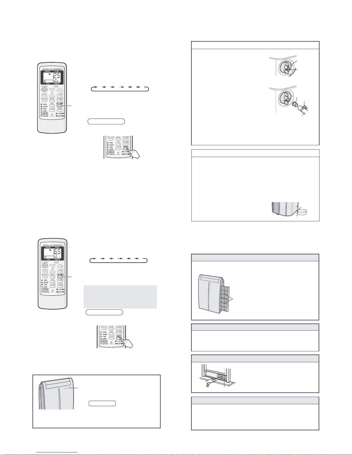
CLEANING THE INSECT GUARD NET
The cooling performance may be reduced or stop
completely if the insect guard net becomes clogged
with dust.
Periodically remove the window exhaust adapter from
the window panel and clean the insect guard net with a
vacuum cleaner or suchlike.
Filters
Be sure to disconnect the power from the wall socket before performing any maintenance.
CLEANING THE FILTERS
If the filter is clogged with dust, the airflow will be reduced, resulting in poor cooling performance. The filter should be cleaned every two weeks.
1
REMOVE THE FILTERS
• Gently pull the filter handle to the right and slide
the filter out of the unit.
2
CLEAN THE FILTERS
• Use a vacuum cleaner to remove any dust. If the
filters are very dirty, wash themwith detergentand
rinse carefully with clean water. Dry the filters in
the shade before reinstalling them.
3
REINSTALL THE FILTERS
• Hold thefilter handleand gentlypush thefilter back
into place.
Never operate the unit without the filter. Doing so
may result in serious damage to the unit.
MAINTENANCE AFTER AIR CONDITIONER SEASON
Insect guard net
9. Timer operation
[8] DRAINAGE
9.1. Off timer
The unit will turn off automatically according to your setting.
Timer duration can be set from a minimum of half an hour (30 minutes) to a
maximum of 12 hours.
Up to 9.5 hours, you can set in half-hour (30-minutes) increments and from 10 to 12
hours, in 1-hour increments.
Display shown when you
set the unit to turn off 2.5
hours later.
NOTES ON TIMER SETTING AND OPERATION
• The latest time setting will be memorized and will appear on the remote control display the next
time you set the OFF TIMER or ON TIMER.
• The OFF TIMER and ON TIMER can not be set together.
Only the most recent TIMER setting will be valid.
• While the ONE-HOUR OFF TIMER is set, the OFF TIMER and ON TIMER is settings are
unavailable.
• If the ONE-HOUR OFF TIMER is set while the OFF TIMER or ON TIMER activated, the ON
TIMER or OFF TIMER setting will be cancelled.
• If a power failure occurs while the OFF TIMER or ON TIMER is set, the TIMER setting will be
cancelled and will not be retrieved even after the power is restored.
Point the remote control at the signal receiver window on the unit.
Press the OFF TIMER button and set the time
1
as desired.
• The time setting will change as you press the
button as follows.
0.5h 1.0h 1.5h 10h 11h 12h
Hold the button down to speed through the settings.
• The orange TIMER lamp on the unit will light.
• The unit will emit a beep when it receives the
1
signal.
• The time setting will count down to show the remaining time.
TO CANCEL TIMER
Press the CANCEL button.
• The orange TIMER lamp on the unit will turn off.
9.2. On timer
The unit will turn on automatically according to your setting.
Timer duration can be set from a minimum of half an hour (30 minutes) to a
maximum of 12 hours.
Up to 9.5 hours, you can set in half-hour (30-minute) increments and from 10 to 12
hours, in 1-hour increments.
Display shown when you set
the unit to turn on 6.5 hours
later.
Point the remote control at the signal receiver window on the unit.
Press the ON TIMER button.
1
• The time setting will change as you press the button
as follows.
0.5h 1.0h 1.5h 10h 11h 12h
Hold the button down to speed through the settings.
• The orange TIMER lamp on the unit will light.
• The unit will emit a beep when it receives the signal.
1
• The time setting will count down to show the remaining time.
Select the mode, temperature, fan speed setting
and PLASMACLUSTER operation as desired.
• When the temperature is set with the ON TIMER,
the temperature will show in the display for 5 seconds and then return to the time display.
• If you do not change the setting, the unit will operate
using the most recent setting.
TO CANCEL TIMER
Press the CANCEL button.
• The orange TIMER lamp on the unit will turn off.
Prepare for drainage and drain out water within the unit in the following cases.
If the unit stops operating and the TIMER, OPERATION and MEGA COOL lamps are
blinking. (This indicates that the water tank inside the unit is full.)
Make sure to turn the unit off.
1
Turn the drainage nozzle to the OPEN
2
position.
Pull the stopcock out from the drainage
3
nozzle.
• When the stopcock is removed, a small amount of
water may be discharged from the drainage nozzle.
Insert the hose clamp into a standard
4
commercially available hose (5/8" inner
diameter, 7/8" outer diameter) and attach
the drain gromment to the hose.
Attach the hose to the drainage nozzle, and
5
secure it with the hose clamp.
• Prepare for draining, as drain water will come out
through the hose during operation.
Press the AUX. button on the unit twice.
6
• The water will drain out through the drainage hose.
Maximum amount of water that may be drained
out is approximately 4
• The OPERATION, TIMER and MEGA COOL
lamps will be blinking.
When drainage water stops running out from the hose, turn the unit off by
7
pressing AUX. button.
• This would take about one minute.
Remove the hose from the drainage nozzle, and replace the stopcock.
8
• Keep the hose clamp and drain grommet in case of re-used.
Turn the drainage nozzle to the CLOSE position.
9
Whenever the unit is moved (to provent water within the unit from spilling).
When the unit is not used for a long time.
Carry out the above procedures from 1 to 5.
1
Press the AUX. button on the unit.
2
• The water will drain out through the drainage hose.
Maximum amount of water that may be drained out is approximately 4
• The OPERATION lamps will light.
When drainage water stops running out from the hose, turn the unit off by
3
pressing AUX. button.
• This would take about one minute.
Remove the hose from the drainage nozzle, and replace the stopcock.
4
• Keep the hose clamp and drain grommet in case of re-used.
Turn the drainage nozzle to the CLOSE position.
5
Remove the stopcock from the drainpipe nozzle, and completely drain any
6
water within the unit.
• Always prepare a receptacle to collect the water
before draining. Maximum amount of water that
may be drained out is approximately
Replace the stopcock to the drainpipe nozzle.
7
1
/5 pints.
2
/5 pints.
"OPEN" position
[9] MAINTENANCE
Drainage
nozzle
Stopcock
Drain grommet
Hose clamp
Hose
1
/5 pints.
Stopcock
Drainpipe nozzle
10. Auxiliary mode
Use this mode when the remote control is not available.
NOTES:
• If the AUX. button is pressed during normal operation, the unit will turn off.
• Upon starting AUXILIARY operation, the drainage pump inside the unit runs for
about a minute, which may produce an audible gurgling sound.
Press the AUX. button on the unit.
1
• The red OPERATION lamp on the unit will
light and the unit will start operating in COOL
1
mode.
• The fan speed is set to AUTO.
• The temperature setting is automatically set
according to the room temperature.
TO TURN OFF
Press the AUX. button again.
• The red OPERATION lamp on the unit will turn off.
2 – 7
Page 11
A
㪈㩹
CVP09FX
CHAPTER 3. DISASSEMBLING PROCEDURE
ServiceManual
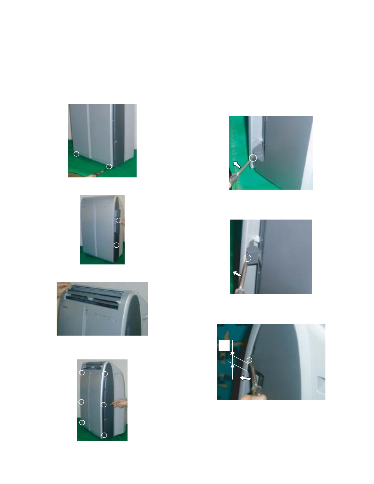
[1] PROCEDURE FOR DISASSEMBLY
"ACTUAL UNITS MAY VARY SLIGHTLY FROM THOSE PICTURES BELOW"
CAUTION:• DISCONNECT THE PORTABLE TYPE ROOM AIR CONDITIONER
1. Unscrew 2 screws holding the front panel on lower both ends.
2. Remove two air filters.
1) Insert flathead screw driver into the position shown in below fig-
CVP09FX
• DISCONNECT THE EXHAUST HOSE FROM THE UNIT BEFORE
• DRAINAGE SHOULD BE PERFORMED BEFORE ANY SERVICE.
(SEE "WHENEVER THE UNIT IS MOVED" OF PAGE 2-7)
ure. Then gently pry the driver to the arrow mark direction, to
unhook the lower hooks (both sides).
3. Open horizontal louvers, as shown in below figure.
4. Unhook 6 hooks of the front panel which is at both sides in an order
from the lower position using flathead screw driver. <6 parts>
2) Insert flathead screw driver into the position shown in below figure. Then gently pry the driver to the arrow mark direction, to
unhook the middle hooks (both sides).
3) Insert flathead screw driver into the position shown in below figure. Then gently pry the driver to the arrow mark direction, to
unhook the upper hooks (both sides).
3 – 1
Page 12
CVP09FX
㪊㩹
㪊㩹
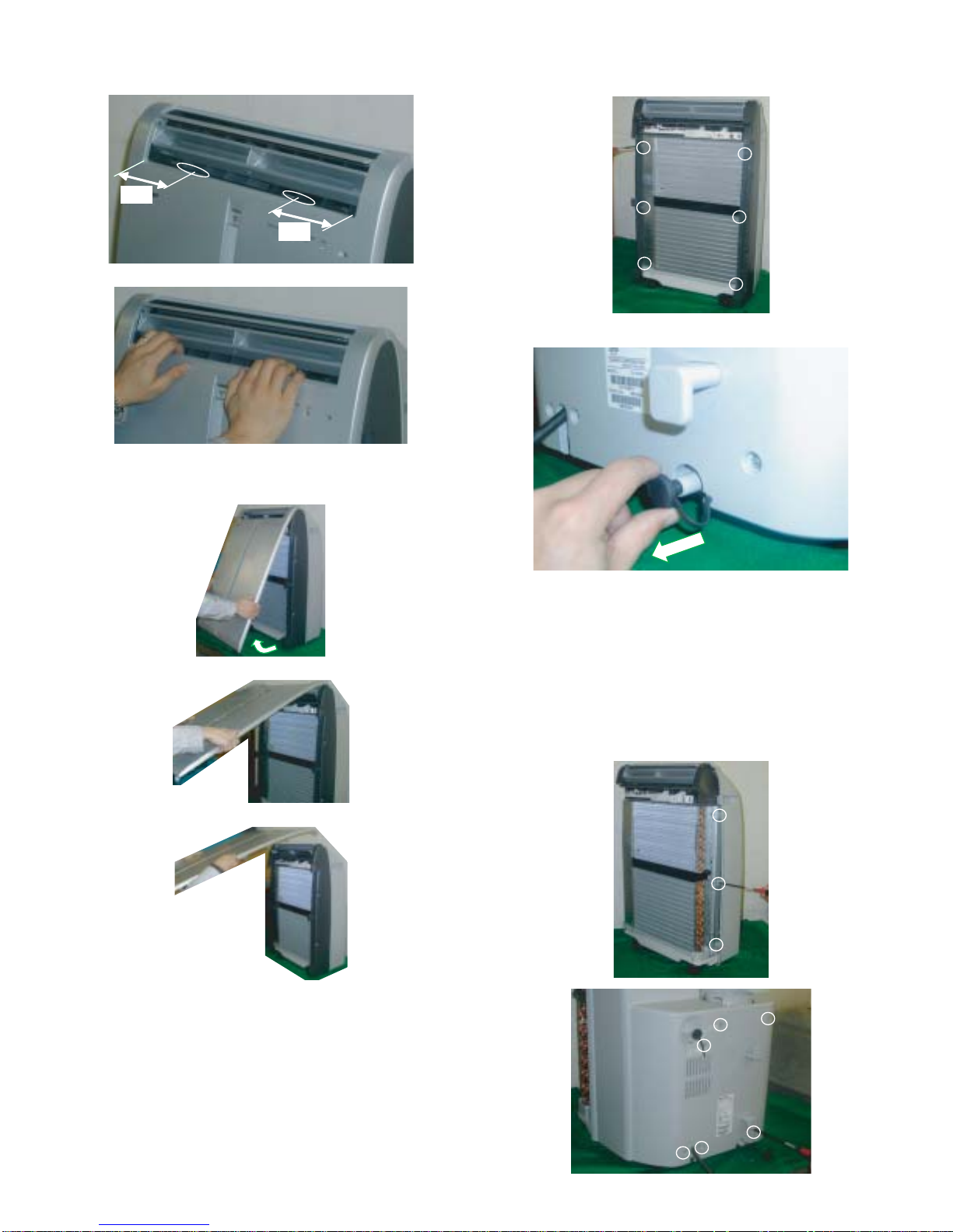
5. Push down the orifice (at position of illustration), as shown in below
figure, to unhook 2 hooks of front panel.
6. Remove the front panel by pulling it at the lower corner toward you
as shown in a figure, and next lift it up and pull it toward you.
7. Unscrew 6 screws holding the side panel L and R.
Remove side panel L and R.
8. Remove the stopcock from the drainpipe nozzle.
* Drain stopcock replacement
• Please check that the stopcock is fully inserted into the
drainage nozzle and drainpipe nozzle when operating at
cooling mode, and after drainage.
• Applying small amount of soapsuds to the stopcock will help
it make easier, if it is difficult to fully insert the stopcock.
9. Unscrew 12 screws holding the cabinet.
6 screws are on each sides.
6 screws are on back side of unit.
3 – 2
Page 13
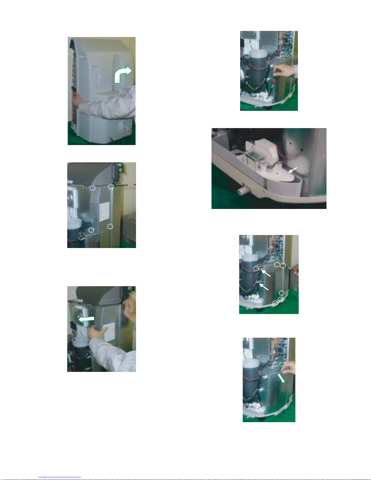
10.Remove the cabinet by lifting it up and pulling toward you as shown
in below figure.
11.Unscrew 4 screws holding the control bo x cover.
CVP09FX
13.Unscrew 2 screws holding the float switch ass’y.
Then move the float switch a little from bulkhead L.
12.Remove the control box cover, as shown in below figure.
CAUTION:DISCHARGE THE FAN MOTOR CAPACITOR AND RUN-
NING CAPACITOR BEFORE TOUCHING THESE CAP ACITORS OR OTHER COMPONENTS OR WIRING.
14.Unscrew 6 screws holding the bulkhead L.
Remove the wire from wire holder.(2 parts)
Then remove the bulkhead L by pulling it toward the arrow mark in
below figure and next lift it up toward you.
3 – 3
Page 14
CVP09FX
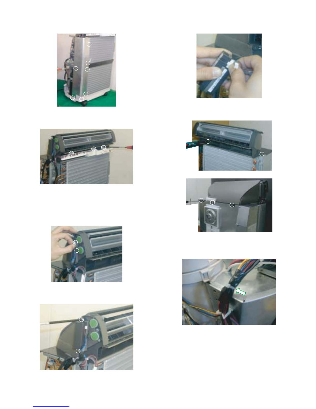
15.Unscrew 7 screws holding the stay angle L.
Remove the stay angle L.
16.Unscrew 3 screws holding the led guide.
Remove the led guide.
19.Remove the plasmacluster unit and cluster cover.
Disconnect the connector of plasmacluster unit.
20.Unscrew 5 screws holding the top duct
Remove the top duct
17.Disconnect two louver motor connectors.
CAUTION:CONNECT THE CONNECTOR OF LOUVER MOTOR
CORRECTLY WHEN RE-ASSEMBLYING.
White connector : Upper louver motor
Black connector : Lower louver motor
18.Unscrew 2 screws holding the cluster holder.
Remove the cluster holder.
21.Cut the fixing band holding the wire and tape. Then remove the
tape.
CAUTION:KEEP THE TAPE IN CASE OF RE-ASSEMBLYING.
3 – 4
Page 15
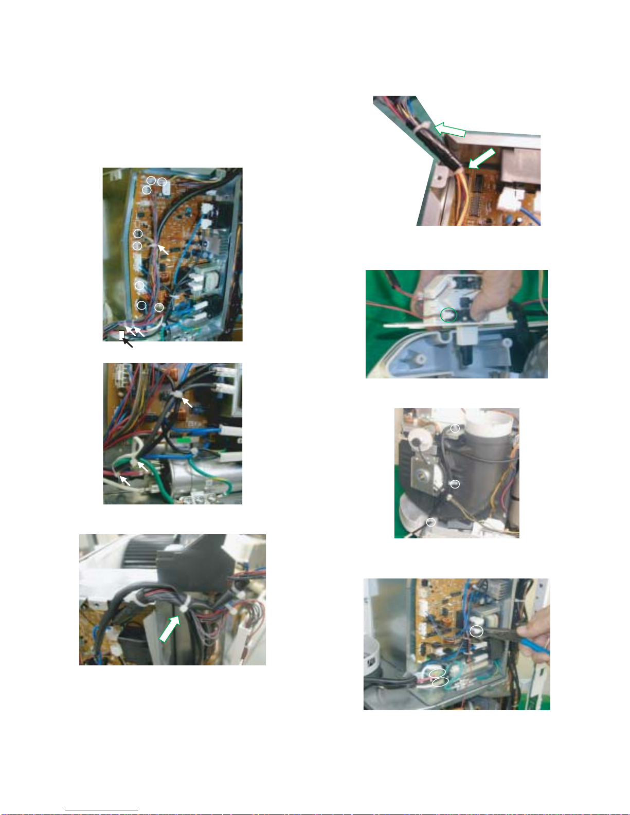
22.Cut the fixing band holding the wires.(7 parts)
Disconnect 8 connectors.
CAUTION:CONNECT THE CONNECTORS OF FAN MOTOR ETC.
CORRECTLY WHEN RE-ASSEMBLYING.
CN6 : OUTDOOR FAN MOTOR(BLACK AND SMALL)
CN4 : INDOOR FAN MOTOR(WHITE AND SMALL)
CN3 : INDOOR FAN MOTOR(WHITE AND LARGE)
CN5 : OUTDOOR FAN MOTOR(BLACK AND LARGE)
CN13 : LEAD WIRE FOR FLOAT SWITCH ASS'Y(4P)
CVP09FX
24.Cut the fixing band holding the wire and tape.
Then remove the tape.
CAUTION:KEEP THE TAPE IN CASE OF RE-ASSEMBLYING.
Then cut the fixing band holding the wires.
25.Disconnect the micro switch connector.
*Lower micro switch only.
23.Cut the fixing band holding the wires.(1 part)
26.Unscrew 3 screws holding the wire holders.
27.Remove wiring connectors of the compressor cord by using longnose pliers.(3 parts)
CAUTION:DISCHARGE THE FAN MOTOR CAPACITOR AND RUN-
NING CAPACITOR BEFORE TOUCHING THESE CAPACITORS OR OTHER COMPONENTS OR WIRING.
3 – 5
Page 16

CVP09FX
28.Unscrew 2 screws holding the control box.
Remove the control box from the unit.
31.Move the band to the direction shown in below figure (approx.11/
16").
Then removed the drain hose B.
29.Unscrew 6 screws holding the casing cover.
Remove the casing cover from the unit.
30.Unscrew 4 screws holding the orifice.
Remove the orifice from the unit.
32.Unscrew the screw holding the lead wire.
33.Turn the band, as shown in below figure.
CAUTION:RETURN THE BAND TO THE ORIGINAL DIRECTION
WHEN RE-ASSEBLYING.
Move the band to the direction of the arrow(approx.11/16"), and
removed the drain hose A.
Then turn the band to the direction, as shown in below figure.
CAUTION:RETURN THE BAND TO THE ORIGINAL DIRECTION
WHEN RE-ASSEMBLYING.
3 – 6
Page 17

34.Unscrew 4 screws holding the half plate.
CVP09FX
36.Unscrew 6 screws holding the stay angle R.
Remove the stay angle R from the unit.
37.Unscrew 3 screws holding the drain pump ass’y.
Remove the drain pump ass’y from the unit.
Then remove the half plate by lifting it up and pulling toward you as
shown in below figure.
35.Unscrew 6 screws holding the out casing.
Remove the out casing from the unit.
38.Unfasten and remove the nut holding the terminal cover at the top
of compressor.
Then remove the wiring connector of the compressor cord.
39.Unscrew the screw holding the centrifugal fan.
Remove the centrifugal fan.
3 – 7
Page 18

CVP09FX
40.Unscrew 4 screws holding the motor cover and wire hold e r.
Remove the motor cover.
Then remove the fan motor.
41.Unscrew the screw holding the centrifugal fan.
43.Remove the 2 motor cushions on each side.
44.Loosen 2 screws holding the motor cover B.
* Do not remove 2 screws and 2 nuts.
45.Remove the motor cover A.
42.Unscrew 5 screws holding the motor cover and wire hold e r.
Remove the motor cover.
Then remove the fan motor.
46.Slide and remove motor cover B, C and D, as shown in b elow figure.
3 – 8
Page 19

CVP09FX
[2] DISASSEMBLING THE CONTROL BOX
CAUTION:DISCHARGE THE FAN MOTOR CAPACITOR AND RUNNING CAPACITOR BEFORE TOUCHING THESE CAPACITORS OR OTHER
COMPONENTS OR WIRING.
1. Cut fixing bands holding the wires.(2 parts)
2. Remove 2 P.W.B.
3. Cut fixing bands holding the wires.(2 parts)
Disconnect 6 connectors.
4. Unscrew 5 screws holding fan motor capacitor, transformer and
lead wire (earth).
5. Remove the control board by unhooking 3 spacers.
3 – 9
Page 20

CVP09FX
CVP09FX
CHAPTER 4. EXPLANATION OF CIRCUIT AND OPERATION
ServiceManual
[1] ELECTRONIC CONTROL CIRCUIT DIAGRAM
ALARM
PUMP
FLOAT
CONTROL
)
SWITCH
(
2
2
(XA)
4
123
1
1W
47
R60
240KR55
240KR54
DRAIN
1
)
FLOAT
SWITCH
(
CN13
R701
1 / 2W 470
2
3
PI701
4
432
R59
BCN701
(XA)
1W
47
(XH)
TH2
INDOOR
CN14
PIPE TMEP.
4.431kW(25ºC)
TH1
312
6.8KF
R51
C38
10µ
+
10K
R48
10kW(25ºC)
ROOM TMP.
16V
10K
R49
:TESTPOINT
(NOTE)
UNLESS OTHERWISE
SPECIFIED, POWER OF
RESISTOR IS 1 /4W.
RES. No.enclosed by rectangleare
124
124
(WHITE)
CN8
(XH)
5V
12V
CHIP PARTS.
LOUVER
3
3
GND
MOTOR
9
(UPPER)
5
5
(BLACK)
CN9
(XH)
PLASMA
CLUSTER
GR
LED503
(LOWER)
LOUVER
MOTOR
2
3
BCN503
Q6
1
321
BCN1
3
5
4
2
1
3
5
4
2
1
IC6
8
9
IC5
8
TIMER
BL
LED502
820
(PH)
R502
CN501
4
7654321
2.7K
R63
2
Q9
3
470
SSR4
RY1
SSR1
R35
470
1W
SSR2
R34
470
1/2W
SSR3
R33
470
1/2W
1.8K
R32
BZ1
IC7
9
OPERATION
LED501
2.7K
R505
R501
123
1W
R36
TURBO
LED504
1.3K
1W
47
R64
JP14
8
IC501
DRAIN
50V
C502
0.1µ
C501
47µ
+
10V
SW1
SW501
4
5
312
5
4
1W
47
R61
10K
3.3K
10K
R44
R46
R39
JP15
JP16
1
DISPLAY & RECEIVER BOARDUNIT
1
(PH)
CN502
CN12
BCN2
213
3.3K
R42
22K
R41
10K
10K
R43
R45
680
R47
TH3
PIPE TMP.
OUTDOOR
10KF
R52
C39
10µ
+
4.431kW(25ºC)
654
6.8KF
R53
C40
16V
16V
10µ
+
10K
R50
C42
10V
100µ
+
ALARM
SW2
D5
DRAIN
21
C4
3A 125V
D7
)
FLOAT
SWITCH
(
TR1
0.1µ
275V
FUSE1
BLACK
USA
AC115V 60Hz
OUT
RY1
L
OUT
IC2
IN
+
IC3
IN
21
+
C18
+
+
D1 ~ 4
NR1
WHITE
N
POWER
C20
10V
C19
BCN3
(JP68)
25V
7812
C17
SUPPLY
PLUG
100µ
7805
50V
47µ
50V
N
0.1µ
JP9
0.1µ
35V1000µ
C41
35V1000µ
C16
NR2
G
C32
50V
20212223242526272829303132P21
MD1
MD0
RST
MB89538
(PATTERN SIDE)
P43
P42
P41
P44
64636261605958575655545352
(WHITE)
(OUTDOOR)
1
IC4
50V
+
3
50V
L2
C10
SSR2
(BLACK)
THERMAL
PROTECTOR
P64
P63
P62
P61
P60
AVss
AVR
AVcc
P57
P56
P55
P54
P53
P52
P51
P50
MD2
P46
P45
100
0.1µ
275V
1µ
C31
C30
9
8
7
6
5
4
3
2
1
0.01µ
JP1
JP2
JP3
JP4
JP5
0.033µ
1W
CN5
(VH)
0.1µ
19
18
17
16
15
14
13
12
11
10
1000p
0.01µ
R3
HOLE
5
6
7
8
0.1µ
SSR1
(C15)
(XA)
CN7
1K
R11
R10
6.8K
C15
275V
0.01µ
11
3
R29
R27
R25
R23
R21
CLUSTER
NONENONE NONE NONE NONE 13K15K15K15K15K13K15K 13K13K13K
NONE
R29R28R27R26R25R24R23R22R21R20
FANSPEED
FANSPEED
FANSPEED
FANSPEED
FANSPEED
MODEL
JP7
MODEL
AUTO
WIRE
JP2 JP3 JP4JP1 JP6JP5
PWR
SYMBOL
OUTDOOR
L
INDOOR
MH
INDOORINDOOR
INDOOR
TURBO
B
SELECT
A
SELECT
RESTART
TEST
LESS
SWEAT
ON
DEF.
CN80
(XA)
1K
R13
1234
R12
6.8K
874
6
5
R28
R26
0.01µ
0.01µ
0.01µ
0.01µ
0.01µ
16V
16V
C34
C33
50V
C29
0.01µ
0.01µ
0.01µ
16V
16V
16V
JP6
JP7
C26
C27
C28
50V
C25
16V
C24
CAPACITOR
C11
MOTOR
275V
FAN
C
1
3
5
BLACK
RED
BLUE
BLACK
C3
FAN
MOTOR
IC
0.1µ
8µF
250V
16V
16V
16V
C35
C36
3.3K
R16
3.3K
R15
3.3K
R14
2
1
Q5
50V
3
C12
C13
0.1µ
312
D
BLUE
BROWN
GRAY
YELLOW
R24
R22
C37
R20
4
3
2
1
IC8
50V
C22
R6
1W
100
C14
275V
R5
0.033µ
50V
0.1µ
R4
(XH)
2K 2W 2K 2W
(BLACK)
CN6
JP13
JP12
JP11
33
34
35
36
37
38
39
40
NC
41
42
43
44
45
46
47
48
5049NC
51
50V
0.1µ
0.01µ
1
SSR4
DRAIN
(PH)
3
PUMP
1
5V
UI1
(VH)
CN2
(INDOOR)
C23
432
UO1
GND
(CN99)
L1
275V
C6
SSR3
R2
(WHITE)
THERMAL
PROTECTOR
0.033µ
1W
CN3
(VH)
100
0.01µ
HOLE
C7
275V
1
5
3
RED
BLUE
BLACK
FAN
MOTOR
IC
JP10
2
1
Q1
R8
22K
TR1 :
PA031
16V
C21
22K
R7
0.01µ
20K
R9
100
1W
COMPRESSOR
C1
60µF 250V
R1
C5
275V
RUNNING CAPACITOR
SA1
P20
P17
P16
P15
P14
P13
P12
P11
P10
P07
P06
P05
P04
P03
P02
P01
P00
P30
P31
NC
CAPACITOR
MOTOR
FAN
A
BLACKBLACK
6µF
C2
250V
8MHz
OSC1
P22
P23
P24
P25
P26
P27X1X0
Vss
NC
NC
IC1
P40
P37
P36
P35
P34
UI1
UO1
Vcc
2
1
Q4
50V
3
C8
50V
C9
0.1µ
0.1µ
CN4
(XH)
213
B
BLUE
BROWN
GRAY
YELLOW
4 – 1
Page 21

[2] PRINTED WIRING BOARD
CVP09FX
4 – 2
Page 22

CVP09FX
[3] FUNCTION
1. Cool Operation
In the "COOL" mode, the thermostat circuit is controlled by 3 thermostat lines(C1~C3).
When the difference between Room Temper ature and Preset Temperature is in [2]~[4] area, compressor is driving or starts driving. If [1]
area is detected, compressor will stop. And indoor fan speed is set as
following speed.
Room Temperature—Preset Temperature
C1 0.9 / 2.7°F
C2 0 / 0.9°F
C3 -2.7 / -0.9°F
Indoor fan speed
Evaporator Temperature
Lower than D3 DH
Higher than D3 DL
D3 53.6 / 60.8°F
Evaporator Temperature
D3
Customer Setting
AUTO
Room Temperature - Preset Temperature
[4]
C1
C2
C3
Indoor fan speed
Area
[4]
[3] CM
[2]
[1]
Customer Setting
LMHAUTO
CL CM CH
[3]
[2]
[1]
CAH
CAL
2. Dehumidification Operation
In the "Dehumidification" Mode, compressor is controlled by room temperature. If it goes over D1 line and gets into the area [3], or if it lowers
than D2 line and gets into the area [1], compressor will stop.
If the evaporator temperature is lower than D3 line, indoor fan speed
will be DH and if the evaporator temperature is higher than D3 line,
indoor fan speed will be DL when the room temperature is in area [2].
Room Temperature
D1 111.2 / 113.0°F
D2 50.0 / 51.8°F
Room Temperature
[3]
D1
D2
[2]
[1]
3. Fan Operation
In the "Fan" mode, compressor and outdoor fan doesn’t operate.
Indoor fan motor operates as follows.
Indoor fan speed
Customer Setting
LMH
AL AM AH
4. Ventilating Operation
In the "Ventilation" mode, compressor and indoor fan doesn’t operate.
Outdoor fan motor operates as follows.
Indoor fan speed
Customer Setting
LMH
600[rpm] 900[rpm] 1200[rpm]
5. Indoor Fan Speed
Fan speeds are given by the indoor fan motor, "DL"~"AH" which are
available in the following operation mode.
In the "COOL" or "DRY" mode, indoor fan speed is different by condenser temperature.
Fan Speed Setting [rpm]
DEHUM
COOL
FAN ONLY
DL - AUTO 400 ~ 500
DH - AUTO 500 ~ 600
CL COOL SOFT - 420 ~ 520
CAL - AUTO 500 ~ 600
WET - - 570 ~ 670
CM COOL LOW AUTO 570 ~ 670
CAH - AUTO 650 ~ 750
CH COOL HIGH - 720 ~ 820
AL FAN ONLY - 520
AM FAN ONLY - 640
AH FAN ONLY - 750
6. Overheating protection system
If the condenser temperature goes over 136.4°F during the cooling or
dry operation, outdoor fan speed will rise to prevent the overloading of
the compressor and restrain the rise in high pressure, and If it lowers
than 134.6°F, outdoor fan speed will return.
If the condenser temperature goes over 158.0°F during the cooling or
dry operation, compressor will stop and if it lowers than 149.0°F, compressor will restart after 3 minutes.
4 – 3
Page 23

7. Freeze preventive
When the indoor pipe temperature falls below 32.0°F during cool operation or dry operation, the compressor is turned off. And if the indoor
pipe temperature rises exceeds 39.2°F after 3 minutes, the compressor will restart.
8. Timer
8.1. OFF TIMER
Set the OFF-TIMER.
The unit will turn off automatically according to your setting. Timer
duration can be set by 0.5 hours to maximum 12 hours. Up to 9.5
hours, you can set by 0.5hours increments and from 10 to 12 hours, by
1 hour increment.
CVP09FX
8.3. ONE-HOUR TIMER
When ONE-HOUR timer is set, the unit turns off automatically after
one hour. The one hour timer operation has priority over other time
operation, such as the TIMER ON and TIMER OFF. If the ONE-HOUR
TIMER button is pressed again during operation, the unit will operate
additionally for another one hour.
9. AUX Button
9.1. Test Run
If the "AUX" button on the unit is pressed for 5 seconds or more during
operation, cool test operation starts. The operation LED (red) flickers
during test run. Continuous compressor on operation is performed.
During Test-Run mode, pump is always ON.
8.2. ON TIMER
Set the ON-TIMER.
The unit will turn on automatically according to your setting. Timer
duration can be set by 0.5 hours to maximum 12 hours. Up to 9.5
hours, you can set by 0.5hours increments and from 10 to 12 hours, by
1 hour increment.
9.2. Aux Operation
If the "AUX" button on the unit is pressed during operation OFF, cooling operation starts.
Then setting Temperature will be is automatically set.
During Aux mode, pump will be ON for 1 minute since start.
10. Te st mode
Keep pushing the "AUX." buttons and supply the power, the system
will go to the test mode. In this mode, the output of operation is
switched by pushing the "AUX." button in the unit or the "OI" button in
the remote controller. Normal outputs are shown in "Self Check Mode
Table"
11. Diagnostic program
When indoor fan motor is out of order or compressor lock or abnormal water level occurs, the compressor, indoor fan motor, outdoor fan motor, and
louver are all stopped and the operation LED(red) turns on or off synchronously with the timing of the timer LED. When the thermistor for room te mperature or pipe temperature is open or short state, the operation LED turns on or off synchronously with the timing of the timer LED by pushing continuously for more than 5 seconds "AUX." button during suspension of operation.
Timer LED
Indoor fan motor
ON
OFF
ON
OFF
1sec
1sec
4sec
Outdoor fan motor
Operation LED
Thermistor short state
Thermistor open state
12. Drain Pump
When drainage is accumulated the float switch becomes close condition and the microcomputer detects this for 1 minute and cause to
operate drain pump. If it has passed for 3 minutes since the microcomputer detects an error by photo interrupter circuit, Compressor will stop
and ALL LED will blink.
ON
OFF
ON
OFF
ON
OFF
13. Plasmacluster
Whenever an indoor machine receives the signal of the plasma cluster
from remote control during air conditioner operation, the operation
mode regarding at the plasmacluster changes in the order of the following.
Clean mode → OFF
4 – 4
Page 24

CVP09FX
14. SELF-CHECK MODE
LED
STEP
0
1
2
3
4
5
6
7
8
9
10
11
RED YELLOW GREEN BLUE A B C D A B C D
Room Temp Eva Temp Cond Temp Test Input
44.6~107.6°F O 28.4~113.0°F O 28.4~113.0°F O P37 = H O
~44.6°F,
107.6°F~
Power On Start
Select
P44 = H O P45 = H O P46 = H O
P44 = L X P45 = L X P46 = L X
2
E
PROM
OK O P40 = H O OK O
NG X P40 = L X NG X
Photo Interrupter Float SW (L)
P64 = H X P63 = H O OK O
P64 = L O P63 = L X NG X
Photo Interrupter Float SW (L) Sweat
P64 = H X P63 = H O P41 = H O P34 = H O
P64 = L O P63 = L X P41 = L X P34 = L X
Bit7 = 1 O Bit6 = 1 O Bit5 = 1 O Bit4 = 1 O
Bit7 = 0 X Bit6 = 0 X Bit5 = 0 X Bit4 = 0 X
Bit3 = 1 O Bit2 = 1 O Bit1 = 1 O Bit0 = 1 O
Bit3 = 0 X Bit2 = 0 X Bit1 = 0 X Bit0 = 0 X
Bit7 = 0 X Bit6 = 0 X Bit5 = 0 X Bit4 = 0 X
Bit7 = 0 X Bit6 = 0 X Bit5 = 0 X Bit4 = 0 X
Bit7 = 0 X Bit6 = 0 X Bit5 = 0 X Bit4 = 0 X
Bit7 = 0 X Bit6 = 0 X Bit5 = 0 X Bit4 = 0 X
Bit7 = 0 X Bit6 = 0 X Bit5 = 0 X Bit4 = 0 X
~28.4°F,
X
113.0°F~
Function Select A Function Select B
Wireless
2
PROM Version
E
2
PROM Version
E
P53 AD Input
P54 AD Input
P55 AD Input
P56 AD Input
P57 AD Input
~28.4°F,
X
113.0°F~
Cond Fan RPM
Eva Fan RPM
X P37 = L X
Input
Input
Auto Restart
Louver
(Upper Side)
Pump
Eva Fan
Cond Fan
Compressor
Plasmacluster
P.I. Power Supply
XXXXXXXXXXXXXX
X XXOXXXOXOXOXOX
OXOXXX
X OOOX
Select
XXXX
XXOO
XXXX
XXOX
XXXX
XXOX
XXXXXXXXXX CLOSEBit7 = 1 O Bit6 = 1 O Bit5 = 1 O Bit4 = 1 O
XXOXXX CLOSE CLOSEBit7 = 1 O Bit6 = 1 O Bit5 = 1 O Bit4 = 1 O
XOXOXOXO
Speed 1
CL
CM
CH
AL
AM
AH
Mega
OPEN X X X X
Speed 2
OPEN OPEN
Speed 3
XXXXXXXX
Speed 4
XXXXXXXX
VL
XXXXXXXXBit7 = 1 O Bit6 = 1 O Bit5 = 1 O Bit4 = 1 O
VM
XXXXXXXXBit7 = 1 O Bit6 = 1 O Bit5 = 1 O Bit4 = 1 O
VH
XXXXXXXXBit7 = 1 O Bit6 = 1 O Bit5 = 1 O Bit4 = 1 O
VH
Louver
(Lower Side)
4 – 5
Page 25

[4] PERFORMANCE CURVES
NOTE: 1) Use this data only as a guide to check the running condition.
2) The running conditions of this data is as follows.
Remote control setting .......... High cool, 64°F
Drain pump ............................. OFF
Exhaust hose .......................... Shortest
3) This data will be changed by operation conditions such as: a drain pump operation or an exhaust hose configuration.
Especially, pump operation will decrease the line current and the power input value significantly.
12.0
70%RH
11.0
10.0
9.0
Line current (A)
8.0
7.0
25ºC
77ºF
Room temperature
30ºC
86ºF
40%RH
CVP09FX
35ºC
95ºF
Power input(W)
temperature
Out let air
1350
1250
1150
1050
950
850
750
30ºC
86ºF
20ºC
68ºF
10ºC
50ºF
25ºC
77ºF
25ºC
77ºF
30ºC
86ºF
Roo m t emp erat ure
30ºC
86ºF
Room t emp erature
70%RH
40%RH
35ºC
95ºF
70%RH
40%RH
35ºC
95ºF
4 – 6
Page 26

CVP09FX
CVP09FX
CHAPTER 5. ATTENTION WHEN REPAIRING
ServiceManual
[1] HOW TO REPAIR REFRIGERATION
Before sealed system work can be preformed a refrigerant recovery EPA and LOCALLY approved certification is required, additionally, EP A
and LOCALLY approved refrigerant recovery equipment is required.
1. Sealed system repair
Sealed system repairs should be properly diagnosed before entering
into a repair of the system.
It is important to follow proper procedures when doing a system repair
for safety reasons and that the repair will result in a restoration of the
system to proper factory standards.
2. Safety reminders
1) Do not heat any system component with an open flame for any reason.
2) Do not solder until you are sure that all refrigerant has been
removed from the system.
3) Do not heat the charging cylinder with an open flame. Use warm
water only and do not exceed 125°F (not too hot to keep your hand
in.)
4) Do not over fill any charging cylinders, as they could explode when
over filled.
5) Use proper wrenches.
6) Use safety goggles when working with refrigerants.
7) Keep a fire extinguisher within easy reach.
8) Watch flame direction when soldering so as not to burn clothing,
wiring or other components.
9) Solder in a well ventilated area. If a high concentration of freon is
present, an open flame will create phosgene gas which can be
harmful.
3. Proper soldering
Joint clearances should be maintained so that the brazing alloy will
flow between the closely mated surfaces rather than forming large fillets.
This films make the strongest joints, capillary attraction also work best
with close tolerance.
The best clearance is between 0.01" to 0.03", the amount of lap will be
approximately 3/8" depending on the swaging tool used.
4. Cleaning tubing
To make a sound, leak tight joint, the brazing alloy when raised to
brazing temperature, must wet and flow freely over the entire surface
of the tubing in the joint area.
To assure this, the tubing surfaces must be free of all dirt, grease, oil
and oxides otherwise the alloy will not wet and flow properly over any
surface with these elements present. Cleaning can be done with an
abrasive cloth or steel wool. Never blow into the tubing because this
will introduce a lot of moisture into the system. Open tubing joints
should be covered if exposed for long periods of time.
EMERY CLOTH
KEEP TUBE IN
DOWNWARD POSITION
Cleaning Tubing.
5. Proper fluxing
Flux is necessary when using silver solder; it is not required when
using silfos on copper to copper joints.
To do a good job the flux should cover the tube surface completely. Be
careful not to introduce any flux inside the tubing.
Fluxing should be done after the tubing is mated together and just
before brazing is done. Do not allow it to dry out.
When brazing, the flux should become entirely liquid and clear, like
water. The temperature will be at 1100°F and only a little more heat will
allow the alloy to flow freely into the joint.
GOOD FIT
PROPER
JOINT FIT
CLEARANCE
0.2mm TO 0.6mm
POOR FIT
Joint Clearance.
5 – 1
10mm
INNER CONE
TORCH STEM
SILVER ALLOY
Directing Torch Flame to Copper Tubing.
Page 27

CVP09FX
HIGH VACUUM PUMP
LARGE DIAMETER
BRAIDED VACUUM
HOSES
HIGH VACUUM
MANIFOLD
DIAL-CHARGE
CHARGING CYLINDER
HIGH SIDE
GAUGE
LOW SIDE
GAUGE
ELECTRIC
VACUUM
GAUGE
TO RELATED SERVICE
VALVE OR PROCESS
TUBES OF THE UNIT.
Hook up for Evacuation
and charging
6. Heating the tubing
Direct the torch flame so that the larger tube receives most of the heat.
Silver solder flows at 1200°F and silfos flows at 1300°F.
Heat all around the tubing.
The flame is composed of two cones, a smaller inner cone (pale blue)
in calor and a much larger outer cone. The hottest part of the flame is
at the tip of the inner cone. The flame should be directed at the joint
with the tip of the cone just touching the surface of the tubing.
Composition of Torch Flame.
7. Dehydrating sealed system
Many servicers feel that since air conditioners run with evaporator temperatures above 33°F, moisture will not present a problem. Nothing is further
from the truth. Oxygen in moisture plus the heat produced during compression will react with the refrigerant oil to produce harmful acids in the system
which will break down motor winding insulation, create sludge and pit comp onent parts, reducing efficiency of the air conditioner and shortening the
life of compressors.
There it becomes mandatory that good dehydrating practices be adhered to at all times.
Proper hook up procedures as shown in Figure 5 must be used in order to pull and good vacuum from the system.
The use of a good vacuum pump is very important so that the boiling point of any water in the system will be lowered to a point where it will vaporize
and be expelled from the system in the form of vapor.
OUTER CONE
HOTTEST PART
OF FLAME
INNER CONE
TORCH STEM
7.1. Type of evacuation methods
1. Piston Type Compressor No good.
System parts must be above 110°F.
2. Rotary Vacuum Pump Disavantages.
Low CFMC. 4 oil gets dirty.
3. Single State Vacuum Pump will not clean oil.
Oil must be changed often.
4. Two Stage Vacuum Pump will reach 50 microns.
First stage is below atmospheric pressure.
Moisture is removed into second stage which works up to atmo-
spheric pressure thus keeping oil clean.
Manometer cannot be read to 1/2 mm. Micron gauge reads from
25,400 microns to 0.
It becomes clear that good equipment and maintained properly must be used in order to remove air and moisture from the system.
When a vacuum of 1,000 to 500 microns is reached, block off the vacuum pump from the system.
This is done by closing the value between the pump and system. If the micron gauge does not increase above 1,000, the system is free of moisture
and no leak exists. If the micron gauge increases to higher levels moisture or a leak exists.
5 – 2
Page 28

CVP09FX
RUNNING CAPACITOR
FAN CAPACITOR
8. Leaks
Several methods are used to detect leaks in systems.
• Electronic Leak Detectors are very sensitive and are able to detect leaks down to 1/2 ounce per year.
A good electronic leak detector is generally far better in locating very small leaks.
• Halide Torch be sure the room is free from refrigerant vapours. Watch the flame for the slightest change in calor.
A very faint green indicates a small leak. The flame will be unmistakably changed to green or purple when large leaks are encountered. To simplify
leak detection pressurize the system to approximately 75 lbs.
Some leaks can be located by a visual inspection of the system components and solder joints and if oil is found at any given location it generally is
a sign that a leak exists at that point due to the fact that flame does carry oil with it travels through the system.
• Soap Bubbles
Liquid detergents can sometimes assist in finding small leaks by brushing detergent on the suspect area and watching for bubbles. Before apply-
ing detergent be sure that the system is pressurized.
Tap line devices are permissible for diagnosis only they are not suitable when evacuat ing the system. After the diag nosis has been made they must
be removed so that the system will be restored to a hermeticly sealed condition.
[2] ELECTRICAL COMPONENT TEST
RUNNING CAPACITOR AND FAN CAPACITOR
NOTE: DISCHARGE THE RUNNING CAPACITOR AND FAN CAPACITOR BEFORE
TOUCHING CAPACITOR OR WIRING.
1) Discharge capacitor by shorting terminals.
2) Take the wires off the capacitor terminals.
3) Set the selector switch of a volt-ohm-meter (or a tester) on the resistance range.
4) Connect the probes to the capacitor terminals and watch the indicator swing.
The indicator does not swing at all ..... Open.
The indicator swings but does not return ..... Shorted.
The indicator swings, then returns a moment later ..... Good.
1. Insulation test
Check the resistance between the terminals and case.
Reading must be more than 10MΩ at DC 500V.
2. Overload relay
Check continuity between terminals with volt-ohm-meter.
3. Insulation test
Check resistance between terminals and the relay case.
Reading must be more than 10MΩ at DC 500V.
4. Compressor
1) Take the wires off compressor terminals.
2) Set selector switch of volt-ohm-meter on the resistance range.
3) Put the probes on the terminals of the compressor and check continuity between each terminal.
5. Insulation test
Check the resistance between the terminals and the copper tube.
Reading must be more than 10MΩ at DC 500V.
5 – 3
Page 29

CVP09FX
CHAPTER 6. TROUBLESHOOTING GUIDE
[1] TROUBLESHOOTING
No cooling
CVP09FX
ServiceManual
Any LED does not turn on
Neither fan nor louver works
The plug was connected
by improper insertion
NO (proper insertion)
Check the Limit SW
for drain water.
Exhaust some water
from the lower outlet.
At first only about 500mL
Water was exhaust. YES YES Check the diagnostic program.
NO
Check the power supply
The wall socket output
under 100V.
Or when the product is
powered on, the voltage is
drop down under 100V.
NO
115V(over 100V)
YES
Some LED turn on.
YES
Some fan or louver
work.
YES YES Check the diagnostic program.
Insert the plug properly.
YES If you use the power supply equipment, check the current capacity of it.
Check the diagnostic program.
Refer to the page(4-4).
Check the display&
detector unit.
Check the operation of
the product.
Any LED does not turn on
NO
Check the operation of
the product.
Any LED does not turn on
Check the indoor wiring capacity.
This product needs more than 15A
Some LED turn on.
Some LED turn on.
Refer to the page(4-4).
EX. For the house fuse, the circuit breaker on the distributing board and
the wires(wire diameter), check the capacity of the current.
NG
Exchange the proper part or equipment.
Refer to the page(4-4).
A
Checking for LCDI
Pull the LCDI out from the wall socket. And remove the LCDI from product.
Push the reset button on the LCDI.(If the LCDI is tripped itself before, you must push the reset button to bring back the common state.)
Put the LCDI into the wall socket.(Check the output of the power supply cord) under 100V NG(out of order)
Push the test button on the LCDI.
(If the LCDI is tripped itself by this action, the LCDI is working normally.) The LCDI did NOT trip. The output is 115V( over 100V.)
Push the reset button on the LCDI to bring back the common state. The LCDI output voltage is 0V .
115V( over 100V)
--
115V
>0V NG(out of order)
--
0V
>115V( or receptacle output voltage) NG(out of order)
While the reset button is pushed ,the power supply cord output is 0V.
OK
When you release the button, the output will be 115V.
6 – 1
Page 30

CVP09FX
A
Check the LCDI
(the power supply cord)
Exhaust water from the lower outlet.
All of them.
Open the panels, and check the power cord output voltage.
Check the voltage between white wire at R-capasitor under 100V
and black wire at main relay(IN) on PWB.
The voltage is under 100V
115V (over 100V) Check the output voltage between white and black wires. Set the product
115V(over 100V)
you must check the insulation Change the power supply cord with LCDI
resistance of compressor. Check the leak current
Push the reset button on the LCDI.
Remove the power supply cord from the product.
Check the power supply cord with LCDI only.
Refer to the page(6-1).
OK NG
under 100V
Check the operation of
the product.
Any LED does not turn on
Check the PWB
(the control board)
The fuse on PWB is short.
short
Measure the insulation
resistance of compressor.
OK(over 10M )
Measure the insulation
resistance of indoor fan motor.
OK(over 10M )
Measure the insulation
resistance of outdoor fan motor.
OK(over 10M )
Can the Compressor operate ?
can operate
YES Check the diagnostic program.
Some LED turn on.
Change the fuse on PWB.
The fuse was open.
And check the cause of over current.
Check the operation of
the product.
Any LED does not turn on
NG(under 10M )
Change the compressor.
NG(under 10M )
Change the indoor fan motor.
NG(under 10M )
Change the outdoor fan motor.
can't operate
Change the compressor.
Refer to the page(4-4).
YES
Some LED turn on.
Check the diagnostic program.
Refer to the page(4-4).
Check the voltage.
The voltage 14V and -12V don't output.
The voltage -5V doesn't output.
Check the operation of
the product.
Any LED does not turn on
Complete the checking
proper output
proper output
proper output(-5V)
EX. Transformer secondary voltage14V, -12V and -5V.
improper output
Check the conduction between 1pin and 6pin of BCN3.
(short or open)
Repair the connection of BCN3 and their
lead wires and the connected limit SW.
YES
Some LED turn on.
Check the diagnostic program.
Refer to the page(4-4).
open
6 – 2
Change the PWB ass'y.
short
Page 31

No cooling
(Fan operate but the
compressor doesn't operate.)
CVP09FX
Measure the power
supply voltage at
receptacle.
120V(over 100V)
I
s it sufficient current
capacity of power
equipment ?
Is it small wiring for power
supply equipment ?
sufficient
Measure the current in
compressor circuit.
current
Check the
overload relay.
OK
Check the
running capacitor.
OK
under 100V
Ask the power supply
company for check.
insufficient
Ask the power supply
company for check.
no current
imperfect contact
Change the
overload relay.
NG
Change the running
capacitor.
Check the
overload relay.
short
Is the connector
disconnecting ?
connecting
Check the compressor
relay.(RY1 on PWB)
OK
open
Change the
overload relay.
disconnecting
Connect properly.
NG
Change PWB ass'y.
Measure the resistance
of compressor coil.
OK
Is there high heat
source near the unit.
there isn't
Is the indoor
temperature too high ?
under 43ºC
Check the outdoor heat
exchanger.
not dirty
Can the compressor
operate ?
can operate
NG
Change the compressor.
there is
Remove the high heat
source or stop.
over 43ºC
Avoid sun light and
ventilate well for outdoor
heat exchanger.
dirty
Clean them with steam
cleaner or another method.
can't operate
Change the compressor.
Check the thermistor.
OK
NG
Change the thermistor.
Checking method for the compressor relay.
(RY1 on PWB)
Turn off the
power supply.
Measure the
resistance of its coil.
OK(about +160Ω on board [20ºC])
Turn on the power
supplty as operating the
compressor.
Measure the
voltage to its coil.
OK(12V, DC)
OK
NG
NG
NG
Checking complete.
6 – 3
Page 32

CVP09FX
No cooling
(The compressor operate but
the indoor fan motor doesn't operate)
crack at the solder part
Repair with over solder. Connect the connector
Check CN3 on PWB
ass'y
OK
Check the indoor fan
motor capacitor. (6µF)
OK
Measure the resistance
of indoor fan motor coil.
OK
Is the indoor fan locked ?
Checking complete
disconnecting the connector
properly.
NG
Change the indoor fan
motor capacitor
NG
Change the indoor fan motor.
locked
Is the fan touched to
another parts ?
no touch
Change the indoor fan motor.
touch
Change fan or another
parts, or adjust.
No cooling
(The compressor operate but
the outdoor fan motor doesn't operate)
crack at the solder part
Repair with over solder. Connect the connector
Check CN5 on PWB
ass'y
OK
Check the outdoor fan
motor capacitor. (8µF)
OK
Measure the resistance
of outdoor fan motor coil.
OK
Is the outdoor fan locked ?
disconnecting the connector
properly.
NG
Change the outdoor fan
motor capacitor
NG
Change the outdoor fan motor.
locked
Is the fan touched to
another parts ?
no touch
Change the outdoor fan motor.
touch
Change fan or another
parts, or adjust.
Checking complete
6 – 4
Page 33

CVP09FX
Operation stops immediately and a
TIMER, OPERATION, and MEGA
COOL lamp blink.
(Indicated of filled with water)
Should be performed drainage.
(See "If the unit stops operating
and the TIMER,OPERATION and
MEGA COOL lamps are blinking."
of page 2-7.)
Can condensation water be drained?
YES
Should be performed drainage.
(See step 6 and 7 "Whenever the unit
is moved." of page 2-7.)
Should be removed the cabinet.
NO
Should be performed drainage.
(See step 6 and 7 "Whenever the unit is moved."
of page 2-7.)
*CAUTION
It is possibility that the tank inside the unit
has filled with condensation water.
(approx. 0.6 gallons.)
Therefore move a unit to the place with
drainage equipment carefully so that the water
may not be spilt.
Then should be performed drainage.
Should be removed the cabinet.
Are disconnecting of "CN2" on the
PWB and pump lead wire?
Connecting
Isn't pump lead wire broken?
GOOD
Should be set it as Step 3 in
test mode.
(See "Test mode" of page 4-4.)
Measure the voltage at "CN2"
on the PWB and pump lead wire.
115V(over 100V)
Should be checked
the drain pump ass'y(drain motor and
pump body etc.).
GOOD
Should be canceled Step 3
in test mode.
*Operation stop.
Disconnecting
NG
Under 100V
NG
Connect them properly.
Change the pump lead wire.
Change the PWB.
Change the drain pump ass'y.
Should be checked movement
of the float ass'y.
GOOD
Should be set it as Step 3 in
test mode.
(See "Test mode" of page 4-4.)
When there is 1st. Micro switch
operation sound can be heard,you
move the float ass'y gradually upward,
and does TIMER lamp (yellow)
put out the light?
Go off
Should be canceled Step 3
in test mode.
*Operation stop.
Should be checked whether to have got
dust etc. blocked in the circulation course
of drainage water.
There are
no dust.
NG
Light up
There are
dust.
Repair or change the float ass'y.
Are disconnecting of "CN12"
on the PWB and micro switch
lead wire?
Connecting
Isn't micro switch lead wire broken?
GOOD
Should be checked micro switch
of upper side(pump control).
GOOD
Should be performed cleaning and
change of dribller,drain valve ass'y
and drain hose.
Disconnecting
NG
NG
Connect them properly.
Change the D-F-S board unit.
Change the micro switch
of upper side(pump control).
Complete.
6 – 5
Page 34

CVP09FX
The compressor doesn't
turn off.
Check the thermistor
connector.
OK
Check the thermistor
resistance.
OK
Check the compressor
relay.
OK
Checking complete.
Insufficient cool air (Compressor and fan motors running)
Temperature set to high?
NO
Air filter or heat exchanger clogged?
NO
Unit is located to close to another heat source?
NO
Exhaust hose is bent or expanded
unnecessarily ?
NO
Another object obstructing exhaust
outlet?
NO
Compressor runs discontinuously?
NO
Variation in temperature of
discharge pipe and Suction pipe
too low?
NO
Frost accumulation around
capillary tube outlet and/or
evaporator inlet ?
NO
disconnecting
Connect the connector
properly.
NG
Change the thermistor.
NG
Change PWB ass'y.
Reset temperature to a lower setting
Clean
Move other heat source
Adjust properly
Remove obstruction
Error light is on?
Thermister attached incorrectly?
Room temperature out of
operation range ?
Power supply voltage too low?
Check the electronical parts
Refrigerant leakage, repair or
change the refrigeration cycle
Lower power current than
normal?
Capillary tube blockage,
change the refrigeration cycle
Checking method for the compressor relay.
(RY1 and PWB)
Turn off the power
supply.
Measure the contact
resistance.
open
OK NG
YES
YES
YES
YES
YES
YES
NO
NO
NO
NO
YES
YES
NO
short
YES
Refer to the manual,
[3] Funtion
11.Diagnostic program
Attach correctly
Remove heat source and ventilate
room
Unplug other appliances
Refrigerant leakage, repair or
change the refrigeration cycle
YES
YES
YES
YES
Unit Check complete
6 – 6
Page 35

Excessive vibration
or Abnormal noise
CVP09FX
Excessive vibration
or Abnormal noise
in fan mode
NO
YES
Check the air filter
Check rotating,
direction of centrifugal
fan.(to clockwise)
Is the fan deformed or
broken.
Is loosened screw
and nut fixing fan ?
not dirty
OK
NO
NO
dirty
Clean the air filter.
NG
Check the fan motor
connector.
Measure the resistance
of fan motor coil.
YES
Change the fan
YES
Tighten up.
OK
OK
NG
Connect properly.
NG
Change the fan motor.
Is each screws
loosened ?
NO
Is pipe touching to
another parts.
NO
Check mounting of
compressor.
OK
Check compressor
noise and vibration.
OK
Checking complete
Checking complete
YES
Tighten up
YES
Repair with adjusting
shape of pipes.
NG
Repair mounting or
change compressor
cushion.
too big
Change compressor.
6 – 7
Page 36

CVP09FX
— MEMO —
6 – 8
Page 37

REPLACEMENT PARTS LIST
PORTABLE AIR CONDITIONER
CVP09FX
[1] OUTSIDE PARTS
[2] INSIDE PARTS
MODEL
CONTENTS
CV-P09FX
[5] ACCESSORY PARTS
[6] PACKING PARTS
[3] CONTROL BOX PARTS
[4] CYCLE PARTS
To have your order filled promptly and correctly, please furnish the
following information.
1. MODEL NUMBER 2. REF. No.
3. PART NO. 4. DESCRIPTION
★ MARK: SPARE PARTS-DELIVERY SECTION
Parts marked with " " are important for maintaining the safety of the set. Be sure to replace these
parts with specified ones for
SHARP CORPORATION
INDEX
“HOW TO ORDER REPLACEMENT PARTS”
ForU.S.A.only
Contact your nearest SHARP Parts Distributor to order.
For location of SHARP Parts Distributor,
Please call Toll-Free;
1-800-BE-SHARP
This document has been published to be used
for after sales service only.
The contents are subject to change without notice.
Page 38

CVP09FX
[1] OUTSIDE PARTS
6-19
1-80
1-61
1-55
6-22
1-115
6-24
1-81
1-78
1-67
1-63
1-76
1-62
1-64
1-77
1-73
1-72
1-74
1-75
1-71
1-68
1-60
1-70
1-66
1-65
6-24
6-24
1-1
1-2
1-5
6-24
1-137
1-6
1-3
6-19
1-7
1-36
1-41
1-56
1-37
1-40
1-39
1-58
1-79
6-19
1-79
6-16
1-38
1-43
1-57
6-19
6-19
1-59
6-19
1-42
1-43
1-42
1-69
6-19
6-19
6-24
1-116
6-24
1-3
1-134
1-4
6-19
6-24
1-132
6-24
6-19
1-83
1-84
2
Page 39

CVP09FX
NO. PARTS CODE
PRICE
RANK
NEW
MARK
PART
RANK
[1] OUTSIDE PARTS
CABINET AND UNIT PARTS
1-1 CCAB-A382JBKZ BG Cabinet ass'y
1-2 GCAB-A292JBFA BL Cabinet
1-3 LHLD-A735JBFA AD Cord holder
1-4 TLAB-C694JBRZ AE Caution label
1-5 TLAB-C797JBRZ AD Caution label
1-6 TLAB-C798JBRZ AD Label
1-7 TLAB-C799JBRZ AD Label
1-36 CPNL-A520JBKZ BD Front panel ass'y
1-37 HBDG-A002KKEA AE Al badge
1-38 HDEC-B192JBFA AF Cluster display
1-39 HPNL-A726JBFA AW Center panel
1-40 HPNL-A727JBFA AZ Display panel
1-41 HPNL-A731JBRA AW Front panel
1-42 PGID-A124JBFA AF Filter gu i de a
1-43 PGID-A125JBFA AF Filter gu i de b
1-55 CKITTA069AKKZ BD Plasmacluster unit
1-56 DLOV-A013JBKZ AZ H louver ass'y
1-57 MLOV-A413JBFA AF Horizontal louver c
1-58 MLOV-A412JBFA AF Horizontal louver b
1-59 GWAKPA173JBFA BC Top duct
1-60 LANG-A623JBPZ AG Top angle
1-61 LHLD-A737JBFA AZ Cluster holder
1-62 LSTP-A027JBFA AM Stopper
1-63 MLOV-A411JBFA AF Horizontal louver a
1-64 PCOV-B108JBFA AZ Cluster cover
1-65 PFPFPC769JBFZ AF Insulator a
1-66 PFPFPC770JBFZ AF Insulator b
1-67 PFPFPC771JBEZ AF Insulator c
1-68 PFPFPC772JBEZ AF Insulator d
1-69 PFPFPC773JBEZ AF Insulator e
1-70 PFPFPC774JBEZ AF Insulator f
1-71 PFPFPC775JBEZ AF Insulator g
1-72 PFPFPC830JBEZ AC Cl.cover insulator b
1-73 PFPFPC831JBEZ AC Cl.cover insulator d
1-74 PFPFPC832JBEZ AC Insulator h
1-75 PFPFPC862JBEZ AC Insulator i
1-76 PSEL-C876JBEZ AC Cluster insulator
1-77 PSEL-C877JBEZ AC Cl.cover insulator a
1-78 PSEL-C879JBEZ AC Cl.cover insulator c
1-79 PSPRCA010JBE0 AD Spring
1-80 QW-VZE971JBZZ AL Lead wire
1-81 RMOT-A061JBE0 AS Louver motor
1-83 DFILMA001JBEA AM Ply filter a
1-84 DFILMA002JBEA AM Ply filter b
1-115 HPNL-A728JBFA AW Side panel l
1-116 HPNL-A729JBFA AW Side panel r
1-132 TLAB-C501JBRZ AC Caution label
1-134 TSPC-E997JBRZ AD Name badge
1-137 TLAB-C822JBRZ AG Caution label
SCREWS AND NUTS
6-16 XTPS730P10000 AC Tapping screw
6-19 XTTS740P12000 AC Tapping screw
6-22 XUPS740P08000 AC Tapping screw
6-24 XTTS740P10000 AC Tapping screw
DESCRIPTION
3
Page 40

CVP09FX
[2] INSIDE PARTS
6-24
1-82
1-45
6-24
2-21
1-28
6-19
1-17
2-2-(3)
2-18
1-46
1-18
1-23
2-2-(2)
1-22
6-24
6-24
1-86
1-19
1-24
6-24
6-24
1-51
1-20
1-9
1-25
6-23
6-5
1-10
1-52
1-20
1-29
1-15
6-24
6-3
6-20
1-19
1-18
6-24
1-26
1-21
6-19
1-121
1-16
6-23
6-5
6-3
6-24
2-19
1-8
6-2
1-114
6-15
6-3
1-111
1-114
6-23
6-5
1-101
1-107
6-19
6-23
1-10
1-15
6-3
1-106
6-17
1-113
1-14
1-112
6-17
1-122
6-19
1-12
6-19
1-108
1-34
1-29
1-11
6-20
1-92
1-13
6-19
1-103
1-97
1-24
6-21
6-24
1-85
1-27
6-2
1-89
1-87
1-53
1-99
6-24
1-50
6-24
1-98
1-138
1-102
1-121
1-29
1-122
6-24
1-48
1-44
1-122
1-54
1-93
1-91
6-19
1-28
6-9
6-24
6-24
6-19
1-91
6-19
1-96
1-123
1-28
1-100
1-117
1-29
1-122
1-94
6-8
1-88
6-19
6-20
1-45
6-24
1-95
6-13
6-19
1-104
6-19
1-14
1-29
6-6
1-90
6-24
6-19
4
Page 41

CVP09FX
NO. PARTS CODE
PRICE
RANK
NEW
MARK
PART
RANK
[2] INSIDE PARTS
CABINET AND UNIT PARTS
1-8 CCHS-A914JBKZ AZ Base pan ass'y
1-9 DCHS-A536JBTA BB Base pan ass'y
1-10 NKOM-A001JBEZ AG Caster
1-11 PGUM-A164JBEZ AE Mot or cushion
1-12 PGUM-A165JBEZ AE Mot or cushion b
1-13 PGUM-A166JBEZ AE Mot or cushion c
1-14 PGUMMA346JBEZ AE Drain plug
1-15 PSEL-C875JBEZ AC Insulator
1-16 PSRA-A172JBFA AX Drain tray
1-17 CKES-A162JBKZ AT Orifice ass'y
1-18 MJNT-A023JBFA AF Louver link
1-19 MLOV-A409JBFA AF Vertical louver a
1-20 MLOV-A410JBFA AF Vertical louver b
1-21 PFPFPC765JBEZ AE Evaporator insulator
1-22 PFPFPC826JBEZ AC Orifice insulator a
1-23 PFPFPC827JBEZ AC Orifice insulator b
1-24 PFPFPC828JBEZ AC Orifice insulator c
1-25 PFPFPC829JBEZ AC Orifice insulator d
1-26 PKESSA090JBFA AX Orifice
1-27 CPMP-A005JBKZ AN Drain pump ass'y
1-28 LBND-A042JBE0 AC Wire fixing band
1-29 LBNDKA132JBEZ AE Band
1-34 PHOS-A045JBEZ AM Drain hose a
1-44 CVLV-A755JBKZ BE Drain valve ass'y
1-45 LANG-A615JBWZ AK Stay angle l
1-46 PCOV-B109JBEZ AG Cover f
1-48 LPLTMA210JBWZ AQ Bulkhead r
1-50 PCOV-B110JBEZ AH Cover r
1-51 LPLTMA211JBWZ AQ Bulkhead l
1-52 PCOV-B111JBEZ AK Cover
1-53 LPLTMA207JBWZ AL Half plat e
1-54 PCOV-B153JBEZ AG Cover t
1-82 DANG-A048JBKZ AZ Stay angle l ass'y
1-85 DPLT-A070JBKZ AU Bulkhead r ass'y
1-86 DPLT-A071JBKZ AW Bulkhead l ass'y
1-87 DPLT-A072JBKZ AW Half plate ass'y
1-88 CMOT-A439JBKZ BL F an motor sub ass'y
1-89 NFANSA045JBFZ AX Centrifugal fan-out
1-90 LANG-A617JBWZ AL Motor cover
1-91 LHLDW0364JBE0 AA Wire holder
1-92 LHLDW0370JBE0 AA Wire holder
1-93 PCOV-B197JBPZ AE Motor cover a
1-94 PCOV-B198JBPZ AG Motor cover b
1-95 PCOV-B199JBPZ AG Motor cover c
1-96 PCOV-B200JBPZ AE Motor cover d
1-97 PKESSA092JBFA AX Out casing a
1-98 PKESSA093JBFA AX Out casing b
1-99 PKESSA094JBFA AX Out casing c
1-100 CMOT-A440JBKZ BG Fan motor sub ass'y
1-101 NFANSA049JBFZ AV Centrifugal fan-in
1-102 LANG-A606JBFZ AM Fan motor angle
1-103 LANG-A614JBPZ AK Casing cover
1-104 LANG-A618JBPZ AK Motor cover in
1-106 PKESSA091JBFZ AX In casing
1-107 DSW-MA003JBKZ AS Float switch ass'y
1-108 CFLO-A001JBKZ AK F loat ass'y
1-111 LHLD-A739JBFA AZ Sw stay
1-112 PCOV-B112JBFZ AF Sw cover
1-113 PFLO-A006JBFZ AE Float c
1-114 QSW-MA009JBZZ AL Micro switch
1-117 LANG-A613JBWZ AR Stay angle r
1-121 LHLDWA042JBEZ AE Wire holder
1-122 LHLDW0366JBE0 AA Wire holder
1-123 LHLDW0368JBE0 AA Wire holder
1-138 PSHE-A231JBEZ AG Motor sheet
CONTROL BOX PARTS
2-18 PCOV-B105JBFZ AG Led guide
2-19 DPWBFA395JBKZ AS D-f-s board unit
2-21 PSHE-A230JBEZ AF Sheet
SCREWS AND NUTS
6-2 LX-BZA360JBEZ AF Special screw
6-3 LX-NZA316JBEZ AF Special nut
6-5 LX-WZA048JBEZ AD Washer
6-6 XBPS730P08J00 AB Machine screw
6-8 XCTS740P10000 AC Tapping screw
6-9 XHTS740P08000 AC Tap tight screw
6-13 XNES730-24000 AE Nut
6-15 XTPS723P14000 AC Tapping screw
6-17 XTPS740P12000 AC Tapping screw
6-19 XTTS740P12000 AC Tapping screw
6-20 XTTS740P14000 AC Tapping screw
6-21 XTTS740P16000 AC Tapping screw
6-23 XWSS700-25000 AC Spring washer
6-24 XTTS740P10000 AC Tapping screw
DESCRIPTION
5
Page 42

CVP09FX
[3] CONTROL BOX PARTS
2-20
2-6
1-28
6-9
2-12
2-11
2-16
2-10
2-15
2-17
6-44
2-13
2-9
2-2
6-42
2-7
-(1)
6-45
6-43
2-4
2-8
6-44
NO. PARTS CODE
PRICE
RANK
6-43
2-3
2-14
NEW
MARK
6-9
PART
RANK
2-5
* Control board unit (2-2) consists of three units.
2-2-(1) · The main control unit with Fuse (2-10).
2-2-(2) · The display & detector unit.
2-2-(3) · The display unit for the cluster.
But we can't deliver the units separatly.
Only you can order Fuse (2-10).
DESCRIPTION
[3] CONTROL BOX PARTS
CABINET AND UNIT PARTS
1-28 LBND-A042JBE0 AC Wire fixing band
CONTROL BOX PARTS
2-1 CACC-A030JBKZ BM Pack ass'y
2-2 DPWBFA394JBKZ BT Control board uint
2-3 LBNDKA130JBWZ AK Capacitor clamp
2-4 LHLDW0366JBE0 AA Wire holder
2-5 PBOX-A450JBWZ AS Control box
2-6 PCOV-B126JBWZ AP Control box cover
2-7 PSPA-A146JBE0 AC Spacer
2-8 PSPA-A177JBZZ AE Pwb spacer
2-9 PSPA-A178JBZZ AE Pwb spacer
2-10 QFS-AA048JBE0 AB Fuse
2-11 QW-VZE964JBZZ AG Lead wire
2-12 QW-VZE985JBZZ AG Lead wire
2-13 QW-VZE999JBZZ AK Lead wire
2-14 RC-HZA484JBZZ AY Running capacitor
2-15 RC-HZA509JBZZ AP Fan motor capacitor
2-16 RC-HZA529JBZZ AR Fan motor capacitor
2-17 RH-HXA047JBZZ AV Thermistor
2-20 TLABCC034JBRZ AD Wiri ng diagram
SCREWS AND NUTS
6-9 XHTS740P08000 AC Tap tight screw (for earth leads & Control box)
6-42 XJTS740P08000 AC Tap tight screw (for the transformer)
6-43 XJTS740P10000 AC Tap tight screw (for Running capacitor & Wire holder)
6-44 XJTS740P12000 AC Tap tight screw (for Fan motor capacitor)
6-45 XCPS740P10000 AE Tapping screw (for Control box ass'y)
2-1
6
Page 43

[4] CYCLE PARTS
<TH2(OR)>
1-120
<TH1(YE)>
<TH3(BK)>
1-28
1-124
1-130
6-24
1-129
1-127
1-28
3-2
3-13
1-128
3-14
3-21
1-131
6-24
1-126
6-14
6-4
3-12
3-20
3-10
3-17
3-6
3-7
3-3
3-4
3-9
3-5
3-1
CVP09FX
3-15
3-16
6-14
6-4
6-14
6-4
NO. PARTS CODE
PRICE
RANK
NEW
MARK
PART
RANK
[4] CYCLE PARTS
CABINET AND UNIT PARTS
1-28 LBND-A042JBE0 AC Wire fixing band
1-120 LHLD-A315JBF0 AE Thermistor holder
1-124 MSPR-A027JBE0 AB Thermistor spring
1-126 PCOV-B154JBEZ AG Cover m
1-127 PFIL-A070JBEZ AE Filter
1-128 PSEL-C882JBEZ AC Drain pan insulator
1-129 PSRA-A174JBFZ AZ Dribller
1-130 PSRA-A173JBFZ AX Drain pan
1-131 QW-IZA083JBZZ AP Comp wiring
CYCLE PARTS
3-1 CPIPCA929JBKZ AX Suction tube ass'y
3-2 DCPY-A340JBKZ AR Capillary tube ass'y
3-3 GLEG-A103JBE0 AG Compressor cushion
3-4 LX-NZA148JBE0 AD Frange nut
3-5 MSPR-A114JBE0 AF Protector spring
3-6 PCOV-A371JBE0 AF Terminal cover
3-7 PSEL-B160JBE0 AH Terminal gasket
3-9 RHOG-A233JBEZ AU Overload relay
3-10 PCMPRA468JBEZ CA Compressor
3-12 LBND-A046JBE0 AE Wire fixing band
3-13 PCON-A544JBEZ BR Condenser
3-14 PEVA-A547JBEZ BL Evaporator
3-15 PFPFPC834JBEZ AD Insulator a
3-16 PFPFPC835JBEZ AD Insulator b
3-17 PGUM-A113JBE0 AH Damper rubber
3-20 PPIPCH210JB1Z AP Discharge tube
3-21 PSEL-C880JBEZ AC Eva insulator
SCREWS AND NUTS
6-4 LX-WZA047JBEZ AC Comp.washer
6-14 XNES780-65000 AC Nut
6-24 XTTS740P10000 AC Tapping screw
DESCRIPTION
7
Page 44

CVP09FX
[5] ACCESSORY PARTS
4-20
4-22
4-21
4-3
4-10
4-4
4-7
4-1
4-15 4-19 4-16
4-2
4-11
4-9
4-26
4-5
4-8
4-25
4-18
4-23
4-17
4-6
4-24
4-12
4-13
4-27
NO. PARTS CODE
PRICE
RANK
NEW
MARK
PART
RANK
[5] ACCESSORY PARTS
4-1 PDUC-A011JBFA AZ Duct hose
4-2 PJNT-A007JBFA AH Connecter c
4-3 SSAKAA109JBEZ AE Bag
4-4 CPNL-A518JBKZ BD Window panel ass'y
4-5 PPNLCA011JBEA AW Window panel a
4-6 PPNLCA012JBEA AP Window panel b
4-7 PPNLCA013JBEA AP Window panel c
4-8 PPNLCA014JBEA AL Panel cover
4-9 SSAKAA111JBEZ AE Bag
4-10 CJNT-A001JBKZ AZ Connecter ass'y
4-11 CRMC-A663JBEZ AY Remote controller
4-12 DX-BZA049JBKZ AS Screw kit
4-13 SSAKAA018YDE0 AB Bag
4-14 XMPS740P25000 AC Wood screw
4-15 LANG-A616JBTA AK Panel angle
4-16 LBNDKA136JBEZ AF Band 5/8
4-17 LHLD-A740JBFA AQ Holder
4-18 PCOV-B115JBFA AG Cover
4-19 PGUMMA347JBEZ AE Drain joint
4-20 PSEL-A931JBE0 AH Window insulator
4-21 PSEL-C848JBEZ AD Panel insulator
4-22 PSEL-C881JBEZ AC Panel insulator
4-23 SPAKCB932JBEZ AH Accessory case
4-24 SSAKHA149YDE0 AC Bag
4-14
DESCRIPTION
8
Page 45

CVP09FX
NO. PARTS CODE
PRICE
RANK
NEW
MARK
PART
RANK
[5] ACCESSORY PARTS
4-25 TINSEA403JBRZ AX Operation manual
4-26 UBATUA027JBE0 AE Battery pack
4-27 TLAB-C807JBRZ AE Caution label
[6] PACKING PARTS
5-2
5-2
5-7
DESCRIPTION
5-5
5-4
5-6
5-3
NO. PARTS CODE
PRICE
RANK
NEW
MARK
PART
RANK
[6] PACKING PARTS
5-1 CPADBA090JBKZ AS Bottom pad ass'y
5-2 CPADBA091JBKZ AR T op pad ass'y
5-3 DPAKCA002JBKZ AX Packing case ass'y
5-4 SPADBA321JBEZ AD Pad
5-5 SSAKHA018JBEZ AF Bag
5-6 SSAKHA245YDE0 AB Protect
5-7 TLABKD765JBRZ AK Number card
PACKING AND ACCESSORIES
ACCESSORY SUB KIT
TOP PAD R
TOP PAD L
DUCT ASS'Y
6
5
4
5-1
DESCRIPTION
2
POWER SUPPLY CORD
PANEL ASS'Y
5
3
PACKING CASE
BAG
BAG
1
BOTTOM PAD ASS'Y
9
Page 46

CVP09FX
INDEX
PARTS CODE No.
[ C ]
CACC-A030JBKZ 3-2-1 BM
CCAB-A382JBKZ 1-1-1 BG
CCHS-A914JBKZ 2-1-8 AZ
CFLO-A001JBKZ 2-1-108 AK
CJNT-A001JBKZ 5-4-10 AZ
CKES-A162JBKZ 2-1-17 AT
CKITTA069AKKZ 1-1-55 BD
CMOT-A439JBKZ 2-1-88 BL
CMOT-A440JBKZ 2-1-100 BG
CPADBA090JBKZ 6-5-1 AS
CPADBA091JBKZ 6-5-2 AR
CPIPCA929JBKZ 4-3-1 AX
CPMP-A005JBKZ 2-1-27 AN
CPNL-A518JBKZ 5-4-4 BD
CPNL-A520JBKZ 1-1-36 BD
CRMC-A663JBEZ 5-4-11 AY
CVLV-A755JBKZ 2-1-44 BE
[ D ]
DANG-A048JBKZ 2-1-82 AZ
DCHS-A536JBTA 2-1-9 BB
DCPY-A340JBKZ 4-3-2 AR
DFILMA001JBEA 1-1-83 AM
DFILMA002JBEA 1-1-84 AM
DLOV-A013JBKZ 1-1-56 AZ
DPAKCA002JBKZ 6-5-3 AX
DPLT-A070JBKZ 2-1-85 AU
DPLT-A071JBKZ 2-1-86 AW
DPLT-A072JBKZ 2-1-87 AW
DPWBFA394JBKZ 3-2-2 BT
DPWBFA395JBKZ 2-2-19 AS
DSW-MA003JBKZ 2-1-107 AS
DX-BZA049JBKZ 5-4-12 AS
[ G ]
GCAB-A292JBFA 1-1-2 BL
GLEG-A103JBE0 4-3-3 AG
GWAKPA173JBFA 1-1-59 BC
[ H ]
HBDG-A002KKEA 1-1-37 AE
HDEC-B192JBFA 1-1-38 AF
HPNL-A726JBFA 1-1-39 AW
HPNL-A727JBFA 1-1-40 AZ
HPNL-A728JBFA 1-1-115 AW
HPNL-A729JBFA 1-1-116 AW
HPNL-A731JBRA 1-1-41 AW
[ L ]
LANG-A606JBFZ 2-1-102 AM
LANG-A613JBWZ 2-1-117 AR
LANG-A614JBPZ 2-1-103 AK
LANG-A615JBWZ 2-1-45 AK
LANG-A616JBTA 5-4-15 AK
LANG-A617JBWZ 2-1-90 AL
LANG-A618JBPZ 2-1-104 AK
LANG-A623JBPZ 1-1-60 AG
LBND-A042JBE0 2-1-28 AC
"3-1-28AC
"4-1-28AC
LBND-A046JBE0 4-3-12 AE
LBNDKA130JBWZ 3-2-3 AK
LBNDKA132JBEZ 2-1-29 AE
LBNDKA136JBEZ 5-4-16 AF
LHLD-A315JBF0 4-1-120 AE
LHLD-A735JBFA 1-1-3 AD
LHLD-A737JBFA 1-1-61 AZ
LHLD-A739JBFA 2-1-111 AZ
LHLD-A740JBFA 5-4-17 AQ
LHLDW0364JBE0 2-1-91 AA
LHLDW0366JBE0 2-1-122 AA
"3-2-4AA
LHLDW0368JBE0 2-1-123 AA
LHLDW0370JBE0 2-1-92 AA
LHLDWA042JBEZ 2-1-121 AE
LPLTMA207JBWZ 2-1-53 AL
LPLTMA210JBWZ 2-1-48 AQ
LPLTMA211JBWZ 2-1-51 AQ
LSTP-A027JBFA 1-1-62 AM
LX-BZA360JBEZ 2-6-2 AF
LX-NZA148JBE0 4-3-4 AD
LX-NZA316JBEZ 2-6-3 AF
PRICE
RANK
NEW
MARK
PART
RANK
PARTS CODE No.
LX-WZA047JBEZ 4-6-4 AC
LX-WZA048JBEZ 2-6-5 AD
[ M ]
MJNT-A023JBFA 2-1-18 AF
MLOV-A409JBFA 2-1-19 AF
MLOV-A410JBFA 2-1-20 AF
MLOV-A411JBFA 1-1-63 AF
MLOV-A412JBFA 1-1-58 AF
MLOV-A413JBFA 1-1-57 AF
MSPR-A027JBE0 4-1-124 AB
MSPR-A114JBE0 4-3-5 AF
[ N ]
NFANSA045JBFZ 2-1-89 AX
NFANSA049JBFZ 2-1-101 AV
NKOM-A001JBEZ 2-1-10 AG
[ P ]
PBOX-A450JBWZ 3-2-5 AS
PCMPRA468JBEZ 4-3-10 CA
PCON-A544JBEZ 4-3-13 BR
PCOV-A371JBE0 4-3-6 AF
PCOV-B105JBFZ 2-2-18 AG
PCOV-B108JBFA 1-1-64 AZ
PCOV-B109JBEZ 2-1-46 AG
PCOV-B110JBEZ 2-1-50 AH
PCOV-B111JBEZ 2-1-52 AK
PCOV-B112JBFZ 2-1-112 AF
PCOV-B115JBFA 5-4-18 AG
PCOV-B126JBWZ 3-2-6 AP
PCOV-B153JBEZ 2-1-54 AG
PCOV-B154JBEZ 4-1-126 AG
PCOV-B197JBPZ 2-1-93 AE
PCOV-B198JBPZ 2-1-94 AG
PCOV-B199JBPZ 2-1-95 AG
PCOV-B200JBPZ 2-1-96 AE
PDUC-A011JBFA 5-4-1 AZ
PEVA-A547JBEZ 4-3-14 BL
PFIL-A070JBEZ 4-1-127 AE
PFLO-A006JBFZ 2-1-113 AE
PFPFPC765JBEZ 2-1-21 AE
PFPFPC769JBFZ 1-1-65 AF
PFPFPC770JBFZ 1-1-66 AF
PFPFPC771JBEZ 1-1-67 AF
PFPFPC772JBEZ 1-1-68 AF
PFPFPC773JBEZ 1-1-69 AF
PFPFPC774JBEZ 1-1-70 AF
PFPFPC775JBEZ 1-1-71 AF
PFPFPC826JBEZ 2-1-22 AC
PFPFPC827JBEZ 2-1-23 AC
PFPFPC828JBEZ 2-1-24 AC
PFPFPC829JBEZ 2-1-25 AC
PFPFPC830JBEZ 1-1-72 AC
PFPFPC831JBEZ 1-1-73 AC
PFPFPC832JBEZ 1-1-74 AC
PFPFPC834JBEZ 4-3-15 AD
PFPFPC835JBEZ 4-3-16 AD
PFPFPC862JBEZ 1-1-75 AC
PGID-A124JBFA 1-1-42 AF
PGID-A125JBFA 1-1-43 AF
PGUM-A113JBE0 4-3-17 AH
PGUM-A164JBEZ 2-1-11 AE
PGUM-A165JBEZ 2-1-12 AE
PGUM-A166JBEZ 2-1-13 AE
PGUMMA346JBEZ 2-1-14 AE
PGUMMA347JBEZ 5-4-19 AE
PHOS-A045JBEZ 2-1-34 AM
PJNT-A007JBFA 5-4-2 AH
PKESSA090JBFA 2-1-26 AX
PKESSA091JBFZ 2-1-106 AX
PKESSA092JBFA 2-1-97 AX
PKESSA093JBFA 2-1-98 AX
PKESSA094JBFA 2-1-99 AX
PPIPCH210JB1Z 4-3-20 AP
PPNLCA011JBEA 5-4-5 AW
PPNLCA012JBEA 5-4-6 AP
PPNLCA013JBEA 5-4-7 AP
PPNLCA014JBEA 5-4-8 AL
PSEL-A931JBE0 5-4-20 AH
PSEL-B160JBE0 4-3-7 AH
PSEL-C848JBEZ 5-4-21 AD
PRICE
RANK
NEW
MARK
PART
RANK
10
Page 47

PARTS CODE No.
PSEL-C875JBEZ 2-1-15 AC
PSEL-C876JBEZ 1-1-76 AC
PSEL-C877JBEZ 1-1-77 AC
PSEL-C879JBEZ 1-1-78 AC
PSEL-C880JBEZ 4-3-21 AC
PSEL-C881JBEZ 5-4-22 AC
PSEL-C882JBEZ 4-1-128 AC
PSHE-A230JBEZ 2-2-21 AF
PSHE-A231JBEZ 2-1-138 AG
PSPA-A146JBE0 3-2-7 AC
PSPA-A177JBZZ 3-2-8 AE
PSPA-A178JBZZ 3-2-9 AE
PSPRCA010JBE0 1-1-79 AD
PSRA-A172JBFA 2-1-16 AX
PSRA-A173JBFZ 4-1-130 AX
PSRA-A174JBFZ 4-1-129 AZ
[ Q ]
QFS-AA048JBE0 3-2-10 AB
QSW-MA009JBZZ 2-1-114 AL
QW-IZA083JBZZ 4-1-131 AP
QW-VZE964JBZZ 3-2-11 AG
QW-VZE971JBZZ 1- 1-80 AL
QW-VZE985JBZZ 3- 2-12 AG
QW-VZE999JBZZ 3- 2-13 AK
[ R ]
RC-HZA484JBZZ 3-2-14 AY
RC-HZA509JBZZ 3-2-15 AP
RC-HZA529JBZZ 3-2-16 AR
RH-HXA047JBZZ 3-2-17 AV
RHOG-A233JBEZ 4-3-9 AU
RMOT-A061JBE0 1-1-81 AS
[ S ]
SPADBA321JBEZ 6-5-4 AD
SPAKCB932JBEZ 5-4-23 AH
SSAKAA018YDE0 5-4-13 AB
SSAKAA109JBEZ 5-4-3 AE
SSAKAA111JBEZ 5-4-9 AE
SSAKHA018JBEZ 6-5-5 AF
SSAKHA149YDE0 5-4-24 AC
SSAKHA245YDE0 6-5-6 AB
[ T ]
TINSEA403JBRZ 5-4-25 AX
TLAB-C501JBRZ 1-1-132 AC
TLAB-C694JBRZ 1-1-4 AE
TLAB-C797JBRZ 1-1-5 AD
TLAB-C798JBRZ 1-1-6 AD
TLAB-C799JBRZ 1-1-7 AD
TLAB-C807JBRZ 5-4-27 AE
TLAB-C822JBRZ 1-1-137 AG
TLABCC034JBRZ 3-2-20 AD
TLABKD765JBRZ 6-5-7 AK
TSPC-E997JBRZ 1-1-134 AD
[ U ]
UBATUA027JBE0 5-4-26 AE
[ X ]
XBPS730P08J00 2-6-6 AB
XCPS740P10000 3-6-45 AE
XCTS740P10000 2-6-8 AC
XHTS740P08000 2-6-9 AC
"3-6-9AC
XJTS740P08000 3-6-42 AC
XJTS740P10000 3-6-43 AC
XJTS740P12000 3-6-44 AC
XMPS740P25000 5-4-14 AC
XNES730-24000 2-6-13 AE
XNES780-65000 4-6-14 AC
XTPS723P14000 2-6-15 AC
XTPS730P10000 1-6-16 AC
XTPS740P12000 2-6-17 AC
XTTS740P10000 1-6-24 AC
"2-6-24AC
"4-6-24AC
XTTS740P12000 1-6-19 AC
"2-6-19AC
XTTS740P14000 2-6-20 AC
XTTS740P16000 2-6-21 AC
XUPS740P08000 1-6-22 AC
XWSS700-25000 2-6-23 AC
PRICE
RANK
NEW
MARK
PART
RANK
CVP09FX
11
Page 48

COPYRIGHT © 2005 BY SHARP CORPORATION
ALL RIGHTS RESERVED.
No part of this publication may be reproduced,
stored in retrieval systems, or transmitted in any
form or by any means, electronic, mechanical,
photocopying, recording, or otherwise, without
prior written permission of the publisher.
SHARP CORPORATION
Appliance Systems Group
Quality & Reliability Control Center
Printed in U.S.A.
 Loading...