

Page 1
SERVICE MANU AL
S3401R5L16EHW
MICROWAVE OVEN
R-5L16
MODEL
In interests of user-safety the oven should be restored to its original
condition and only parts identical to those specified should be used.
TABLE OF CONTENTS
CAUTION, MICROWAVE RADIATION....................................................................................................... 1
WARNING....................................................................................................................................................1
PRODUCT SPECIFICATIONS ................................................................................................................... 2
GENERAL IMPORTANT INFORMATION ...................................................................................................2
APPEARANCE VIEW ................................................................................................................................. 3
OPERATION SEQUENCE.......................................................................................................................... 4
FUNCTION OF IMPORTANT COMPONENTS .......................................................................................... 5
SERVICING ................................................................................................................................................ 7
TEST PROCEDURE................................................................................................................................... 9
COMPONENT REPLACEMENT AND ADJUSTMENT PROCEDURE..................................................... 15
MICROWAVE MEASUREMENT .............................................................................................................. 20
TEST DATA AT A GLANCE ..................................................................................................................... 21
WIRING DIAGRAM................................................................................................................................... 22
PICTORIAL DIAGRAM ............................................................................................................................. 23
PARTS LIST ............................................................................................................................................. 24
R-5L16
Page
SHARP CORPORATION
Page 2

R-5L16
CAUTION
MICROWAVE RADIATION
Personnel should not be exposed to the microwave energy which may radiate from the
magnetron or other microwave generating devices if it is improperly used or connected.
All input and output microwave connections, waveguides, flanges and gaskets must be
secured.
Never operate the device without a microwave energy absorbing load attached.
Never look into an open waveguide or antenna while the device is energized.
VARNING
MICKROVAGSSTRALING
Personal får inte utsättas för mikrovågsenergi som kan ustrala från magnetronen eller
andre mikrovågsalstrande anordningar om dessa är felanslutna eller används på fel sätt.
Alla in-och utgångsanslutningar för mikrovågor, vagledare, flänsar och packningar måste
vara fast anslutna.
Mikrovågsgeneratorn får inte arbeta utan att absorberande belastning är ansluten. Titta
aldrig in i ën öppen vågledare eller antenn när mikrovågsgeneratorn är påkopplad eller
laddad.
VAROITUS
MIKROAALTOSÄTELYÄ
Käyttäjä ei saa joutua alttiiksi mikroaaltoenergialle, jota voi säteillä magnetronista tai
muusta mikroaaltoja kehittävästä laitteesta, jos sitä käytetään tai jos se kytketään väärin.
Kaikkien mikroaaltoliitäntöjen sekä syöttö-että ulostulopuolella, aaltoputkien laippojen ja
tiivisteiden tulee olla varmistettuja.
Mikroaaltouunnia ei koskaan saa käyttää ilman kuormaa jossa mikroaaltoenergiaa kuluu.
Avoimeen aaltoputkeen tai antenniin ei koskaan saa katsoa virran ollessa kytkettynä.
ADVARSEL
MIKROBØLGESTRÅLING
Personell må ikke utsettes for mikrobølge-energi som kan utståles fra magnetronen eller
andre mikrobølge-generende deler dersom apparatet feilbetjenes eller blir feiltikoplet.
Alle inn-og ut-tilkoplinger i forbindelse med mikrobølge-strålingen, bølgeledere, flenser og
tetningsringer/pakninger må festes ordentlig.
Aldri bruk apparatet med mindre en mikrobålge-absorberende last er plassert i
ovnsrommet.
Aldri se direkte inn i en åpen bølgeleder eller antenne imens apparatet er strømførende.
ADVARSEL
MIKROBØLGEBESTRÄLING
Man bør ikke udsætte sig for mikrobølgebestråling fra magnetronen eller andre
mikrobølgefrembringende anordninger, hvilket kan ske hvis apparatet er forkert tilsluttet
eller bruges forkert. Alle mikrobølgeindgange og-udgange, bølgeledere, flanger og
tætningsstrimler må være forsvarligt udført.
Anvend aldrig ovnen uden en mikrobølgesabsorberende anordning. Se aldrig ind i en
åben bølgeleder eller antenne, mens ovnen er i brug.
Page 3
SERVICE MANUAL
R-5L16
MICROWAVE OVEN
R5L16
GENERAL IMPORTANT INFORMATION
This Manual has been prepared to provide Sharp Corp. Service
engineers with Operation and Service Information.
It is recommended that service engineers carefully study the entire
text of this manual, so they will be qualified to render satisfactory
customer service.
WARNING
Note: The parts marked "*" are used in voltage more than 250V.
(Parts List)
All the parts marked "∆" on the parts list may cause undue
microwave exposure, by themselves, or when they are
damaged, loosened or removed.
Anm: Delar märket med "*" har en spänning överstigande
250V.
Alla reservdelar som är märkta med "∆" i reservdelslistan
kan förorsaka omåtting mikrovågsstrålning, antingen i sig
själva, eller när de har blivit skadade, lösa eller.
Huom: Huolto-ohjeeseen merkitty "tähdella" osat joissa jännite
on yli 250 V.
Kaikki varaosaluettelossa ∆:lla merkityt osat voivat
aiheuttaa asiaankuulumatonta mikroaaltosäteilyä; joko
sinällään, tai kun ne ovat rikki, löystyneet tai irroitettu.
Bemerk: Deler som er merket "asterisk" er utsatt for spenninger
over 250V til jord.
Alle delene som er merkt med "∆" på del-listen kan
forårsake utstrakt mikrobølgestråling, og denne faren
øker når de er skadet, løsner eller fjernes.
Bemærk: "Dele mærket med stjerne benyttes med højere spænding
end 250 volt.
Alle delene mærket "∆" på delbetegnelsen på medføre
udsættelse for mikrobølger, af sig selv eller når de bliver
beskadigede, løsnede eller fjernet.
PRODUCT SPECIFICATIONS
GENERAL INFORMATION
APPEARANCE VIEW
OPERATING SEQUENCE
FUNCTION OF IMPORTANT
COMPONENTS
SERVICING AND
TROUBLESHOOTING CHART
TEST PROCEDURE
COMPONENT
REPLACEMENT AND
ADJUSTMENT PROCEDURE
MICROWAVE MEASUREMENT
WARNING
Never operate the oven until the following points are ensured.
(A) The door is tightly closed.
(B) The door brackets and hinges are not defective.
(C) The door packing is not damaged.
(D) The door is not deformed or warped.
(E) There is not any other visible damage with the oven.
Servicing and repair work must be carried out only by trained service
engineers.
SHARP CORPORATION
OSAKA, JAPAN
1
TEST DATA AT A GLANCE
WIRING DIAGRAM
PARTS LIST
Page 4
R-5L16
PRODUCT DESCRIPTION
SPECIFICATION
ITEM DESCRIPTION
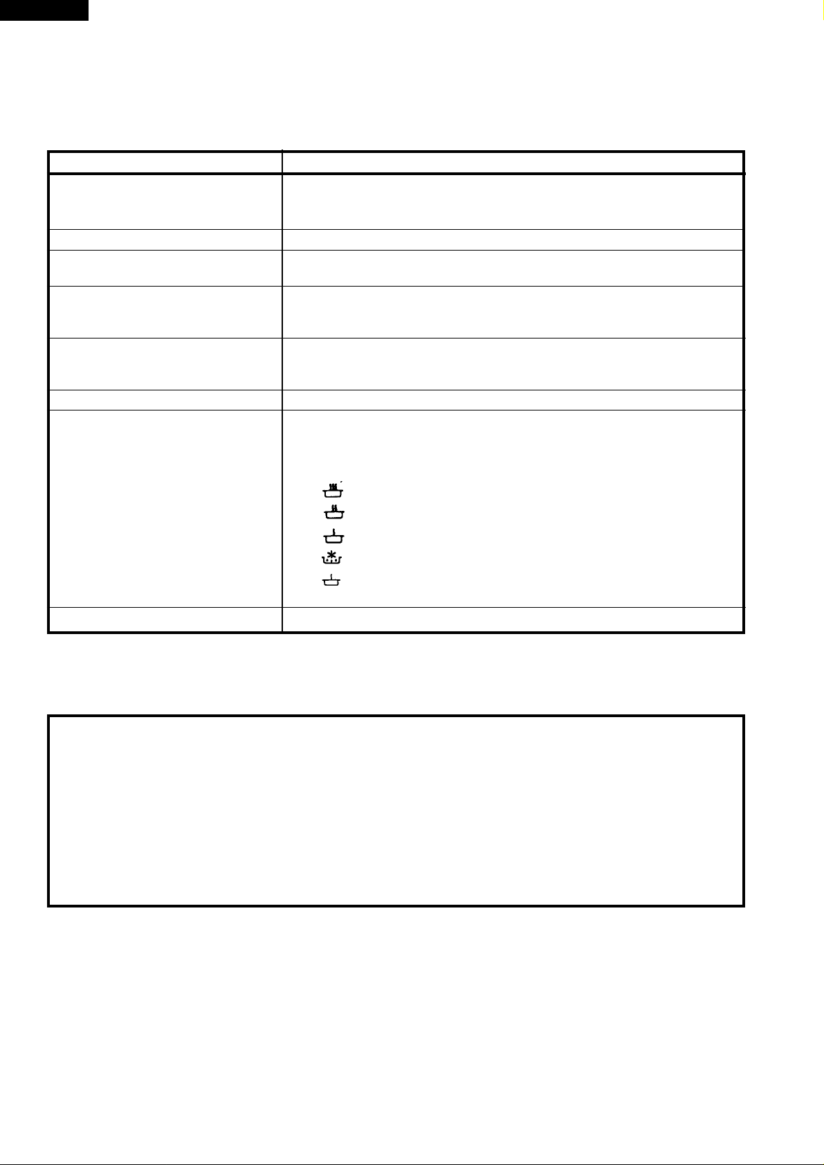
Power Requirements 220-230 Volts
50 Hertz
Single phase, 3 wire earthed
Power Consumption 1750 W Approx. 8 A
Power Output 1000 W nominal of RF microwave energy (measured by method of IEC 705)
Operating fequency 2450 MHz
Case Dimensions Width 520 mm
Height 305 mm including foot
Depth 413 mm
Cooking Cavity Dimensions Width 342 mm
Height 193 mm
Depth 368 mm
Turntable diameter 325mm
Control Complement 30 min. Single-speed timer
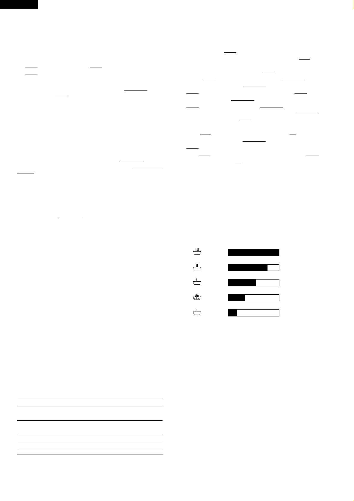
Microwave Power for Variable Cooking
Repetition Rate;
HIGH ........... Full power throughout the cooking time
MEDIUM HIGH............ approx. 70% of FULL Power
MEDIUM...................... approx. 50% of FULL Power
MEDIUM LOW ............. approx. 30% of FULL Power
LOW ............................ approx. 10% of FULL Power
Set Weight (Approx.) Approx. 17.0 kg
GENERAL INFORMATION
WARNING
THIS APPLIANCE MUST BE EARTHED
IMPORTANT
THE WIRES IN THIS MAINS LEAD ARE COLOURED IN ACCORDANCE WITH THE FOLLOWING CODE:
GREEN-AND-YELLOW : EARTH
BLUE : NEUTRAL
BROWN : LIVE
2
Page 5
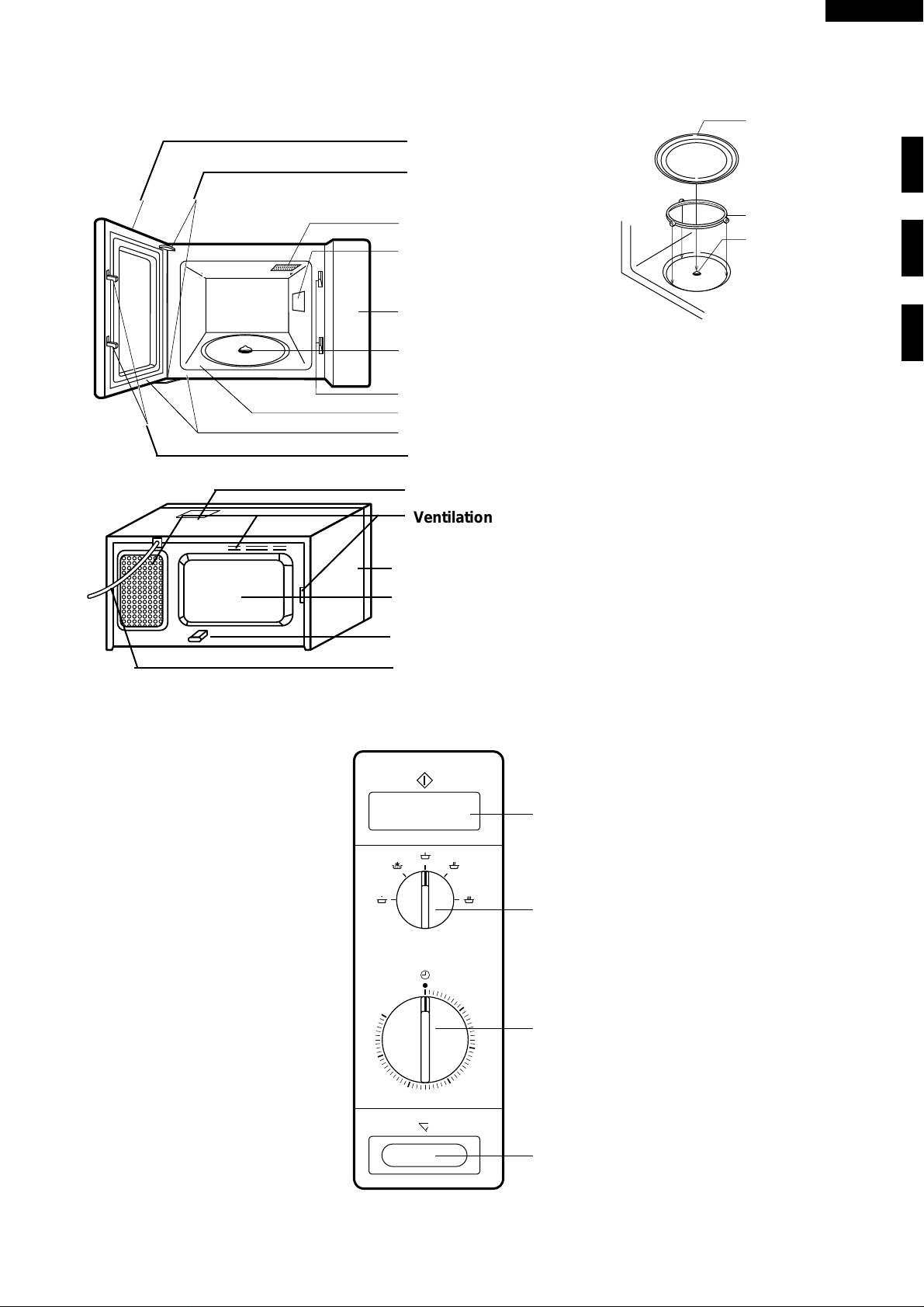
APPEARANCE VIEW
R-5L16
OVEN
Door
Door hinges
Oven lamp
Waveguide cover
Control panel
Coupling
1. Place the roller stay on the floor of
the oven cavity.
2. Then place the turntable on it fitting
Door lock opening
to the coupling.
Oven cavity
Door seals and sealing surfaces
Safety door latches
Oven lamp access cover
Ventilation openings
Turntable
Roller Stay
Coupling
CONTROL PANEL
30
25
Outer cabinet
Rear cabinet
Spacer
Power supply cord
START BUTTON
MICROWAVE POWER
CONTROL
5
TIMER (0 - 30 mim)
10
15
20
DOOR OPEN BUTTON
3
Page 6
R-5L16
OPERATION SEQUENCE
OFF CONDITION
1. When the timer knob is at " • ", the oven is OFF condition.
2. Closing the oven door activates the primary latch switch
SW1, the 2nd latch switch SW2, and the 3rd latch switch
SW3.
IMPORTANT:
When the oven door is closed, the contacts
monitor switch
SW5 must be open.
COM-NC of the
Figure O-1 on page 22
3. When the microwave oven is plugged in a wall outlet
(220-230V, 50Hz), the noise filter is energized.
4. When the oven door is opened, the oven lamp lights.
MICROWAVE COOKING CONDITION
HIGH COOKING
When the door is closed, the contacts
primary latch, 2nd latch and 3rd latch switches
+ SW3 are activated.
When the microwave power control is set to “ HIGH ” position
and cooking time is selected by turning the timer and push
the start button, the following operations occur: (Figure 0-2)
1. The contacts of the timer motor and vari switch are closed.
2. The contacts (
COM-NO) of the cook switch are closed.
3. Then following components are energized.
COM-NO of the
SW1 + SW2
8. MONITOR SWITCH CIRCUIT
The monitor switch
oven door and monitors the operation of the relay
SW5 is mechanically controlled by the
RY1.
8-1. When the oven door is opened during or after a cooking
cycle, the primary latch switch
SW3 must open their contacts (COM-NO) first.
switch
After that the contacts (
COM-NC) of the monitor switch
SW1 and the 3rd latch
SW3 can be closed and the 2nd latch switch SW2 must
open its contacts (
COM-NO). And then the cook switch
SW4 must open its contacts (COM-NO).
8-2. When the oven door is closed, the contacts (
of the monitor switch
SW5 must be opened.
COM-NC)
8-3. When the oven door is opened and the contacts of the
RY1 remain closed, the fuse F6.3A F1 will blow,
relay
because the contacts (
COM-NC) of the monitor switch
SW5 are closed and a short circuit is caused through the
RY1, the monitor resistor R1 monitor switch SW5,
relay
and the fuse F6.3A
F1
MEDIUM HIGH, MEDIUM, MEDIUM LOW, LOW
COOKING
When the microwave oven is preset for variable cooking
power, the 220-230 volts A.C. power is supplied to the high
voltage transformer intermittently within a 26.4-second time
base through the vari switch. The following levels of microwave power are given.
Oven lamp High voltage transformer
Timer motor Fan motor .
Turntable motor Magnetron
Surge relay RY2 Relay RY1
The line voltage is supplied to the primary winding of the
high voltage transformer. The voltage is converted to
about 3.3 volts A.C. on the filament winding, and
approximately 2000 volts A.C. on the secondary winding.
4. The 3.3 volts filament winding voltage heats the magnetron
filament and the 2000 volts secondary winding voltage is
sent to a voltage doubler circuit, where it is doubled to a
negative voltage of approximately DC 4000 volts.
5. The 2450MHz microwave energy produced in the
magnetron generates a wave length of 12.24 cm. This
energy is changed through the waveguide (transport
channel) into the oven cavity, where the food is placed to
be cooked.
6. Upon completion of the selected cooking time, the timer
bell rings, and contacts of the timer are open, then the
activated components as item 2 are de-energized.
7. When the door is opened during a cooking cycle, the
switches come to the following positions.
Condition
Switch Contact Durning Oven Door
Cooking Open(No cooking)
primary latch Switch COM-NO Closed Opened
COM-NC Opened Closed
2nd latch switch COM-NO Closed Opened
Monitor Switch COM-NC Opened Closed
3rd latch switch COM-NO Closed Opened
SETTING
26.4 sec. ON
HIGH
20.4 sec. ON
MEDIUM HIGH
14.5 sec. ON
MEDIUM
8.6 sec. ON
MEDIUM LOW
4.4 sec. ON
LOW
6 sec. OFF
Approx. 70%
11.9 sec. OFF
Approx. 50%
17.8 sec. OFF
Approx. 30%
22 sec. OFF
Approx. 10%
Note: The ON/OFF time ratio does not exactly correspond
to the percentage of microwave power, because
approx. 3 seconds are needed for heating up the
magnetron filament.
4
Page 7
FUNCTION OF IMPORTANT COMPONENTS
R-5L16
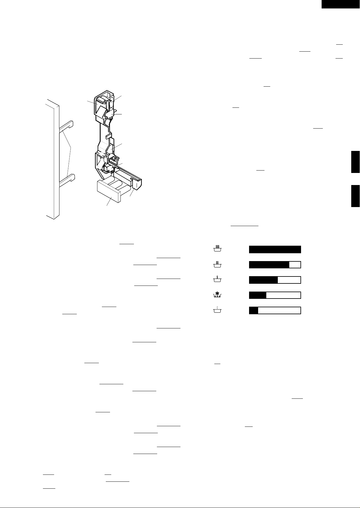
DOOR OPEN MECHANISM
The door can be opened by pushing the door open button on
the control panel. When the door open button is pushed, the
cook lever is moved upward, operating the latch head. The
latch head is moved upward, and released from the latch
hook. Now, the door can be opened.
2ND. LATCH
LATCH HOOK
LATCH
HEADS
DOOR OPEN BUTTON
SWITCH
PRIMARY
LATCH SWITCH
MONITOR
SWITCH
3RD. LATCH
SWITCH
OPEN LEVER
Figure D-1. Door Open Mechanism
PRIMARY LATCH SWITCH SW1
1. When the oven door is closed, the contacts (COM-NO)
must be closed and the contacts (
COM-NC) must be
opened.
2. When the oven door is opened, the contacts (
must be opened and the contacts (
COM-NC) must be
COM-NO)
closed.
2ND LATCH SWITCH SW2 AND 3RD LATCH
SWITCH
SW3
CAUTION: BEFORE REPLACING A BLOWN FUSE
F6.3A TEST THE RELAY
SWITCH
SW3 AND MONITOR RESISTOR R1
RY1, MONITOR
F1
FOR PROPER OPERATION. (REFER TO
CHAPTER “TEST PROCEDURE.)
MONITOR RESISTOR Rl 4.3Ω 20W
The monitor resistor prevents the fuse F1 F6.3A bursting
when the fuse
F1 F6.3A blows due to the operation of the
monitor switch.
TIMER MOTOR (WITH VARI-SWITCH) TM
Timer contacts
1. When the timer is at “
TM are opened.
2. When the timer is turned clockwise from “
contacts of the timer
Vari-contacts (COM-NO):
The vari-contacts are operated by the cam roller. If the
variable cooking control is set at MEDIUM HIGH, MEDIUM,
MEDIUM LOW or LOW cooking position, the line voltage is
supplied to the high voltage transformer intermittently within
a 26.4 seconds time base. The following chart shows the
vari-contacts (
COM—NO) operation in the various modes.
SETTING
HIGH
MEDIUM HIGH
MEDIUM
MEDIUM LOW
LOW
• “ position, the contacts of the timer
•” position, the
TM are closed.
26.4 sec. ON
20.4 sec. ON
14.5 sec. ON
8.6 sec. ON
4.4 sec. ON
6 sec. OFF
Approx. 70%
11.9 sec. OFF
Approx. 50%
17.8 sec. OFF
Approx. 30%
22 sec. OFF
Approx. 10%
1. When the oven door is closed, the contacts (COM-NO)
must be closed.
2. When the oven door is opened, (
COM-NO) must be
opened.
COOK SWITCH SW4
1. When the oven door is closed and the start button is
pushed, the contacts (
2. When the oven door is opened, (
COM-NO) must be closed.
COM-NO) must be
opened.
MONITOR SWITCH SW5
1. When the oven door is closed the contacts, (COM-NC)
must be opened and the contacts (
closed.
2. When the oven door is opened the contacts, (
must be closed and the contacts (
closed.
3. If the oven door is opened ,and the contacts of the relay
RY1 fail to open, the fuse F1 F6.3A blows simultaneously
with closing the contacts (
COM-NC) of the monitor switch
SW5
COM-NO) must be
COM-NC)
COM-NO) must be
Note: The ON/OFF time ratio does not exactly correspond
to the percentage of microwave power, because
approx. 3 seconds are needed for heating up the
magnetron filament.
FUSE Fl F6.3A 250V
1. If the wire harness or electrical components are shortcircuited, this fuse blows to prevent an electric shock or
fire hazard.
2. The fuse also blows when the relay
RY1 remains closed
with the oven door open and when the monitor switch
SW5 closes.
SPECIAL FUSE F2
1. If the wire harness or electrical components are shortcircuited, this fuse blows to prevent an electric shock or
fire hazard.
2. The fuse blows when the asymmetric rectifier, H.V.
rectifier, H.V. wire harness, H.V. capacitor, magnetron or
secondary winding of high voltage transformer is shorted.
5
Page 8
R-5L16
THERMAL CUT-OUT 125°C TC1 (MG)
The thermal cut-out protects the magnetron against overheat. If this temperature goes up higher than 125°C because
the fan motor is interrupted, the ventilation openings are
blocked, the thermal cut-out TC1 will open and line voltages
to the high voltage transformer T will be cut off and the
operation of the magnetron MG will be stopped. The defective
thermal cut-out TC1 must be replaced with new one.
THERMAL CUT-OUT 125°C TC2 (OVEN)
The thermal cut-out located on the top of the oven cavity is
designed to prevent damage to the oven if the foods in the
oven catch fire due to over heating produced by improper
setting of cook time or failure of control unit. Under normal
operation, the oven thermal cut-out remains closed. However, when ab-normally high temperatures are reached within
the oven cavity, the oven thermal cut-out will open at 125°C,
causing the oven to shut down. The defective thermal cut-out
TC2 must be replaced with new one.
TURNTABLE MOTOR
The turntable motor drives the turntable roller assembly to
rotate the turntable.
FAN MOTOR
The fan motor drives a blade which draws external cool air.
This cool air is directed through the air vanes surrounding the
magnetron and cools the magnetron. This air is channelled
through the oven cavity to remove steam and vapours given
off from the heating foods. It is then exhausted through the
exhausting air vents at the oven cavity.
NOISE FILTER
The noise filter prevents the radio frequency interference that
might flow back in the power circuit.
SURGE RELAY RY AND SURGE RESISTOR R2
Ω/20W
10
2. After approx, 6msec. the contacts of the surge relay RY2
close and the line voltage is supplied to the high voltage
transformer T.
3. If the surge resistor R2 is defective, the home fuse or fuse
F2 may break down when the oven is switched on.
4. If the contacts of the surge relay RY2 remains opened after
6msec. since the oven is switched on the temperature of
the surge resistor R2 of may rise high and may damage
the electric or mechanical parts around the surge resistor
R2.
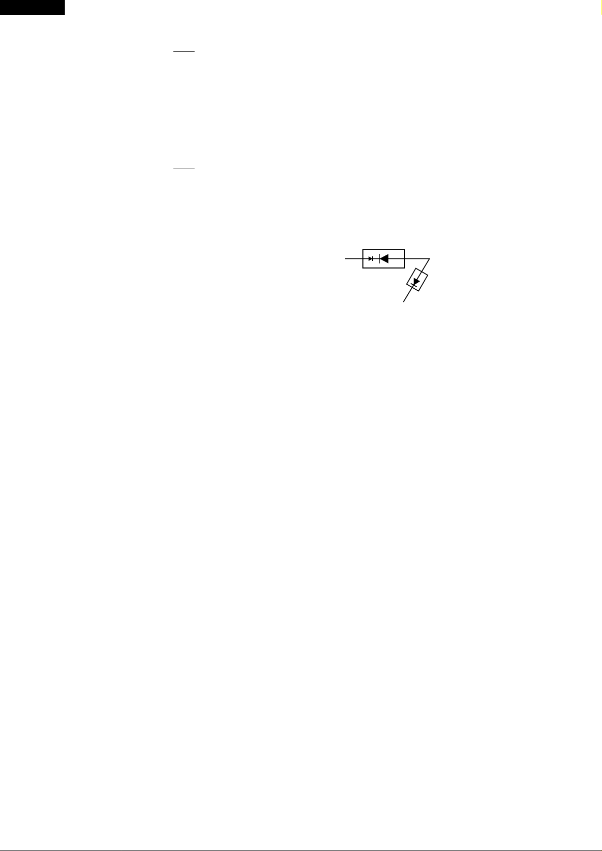
ASYMMETRIC RECTIFIER
The asymmetric rectifier is a solid state device that prevents
current flow in both directions. And it prevents the temperature rise of the high voltage transformer by blowing the
special fuse F2 when the high voltage rectifier is shorted.
AB
D2 D1
ASYMMETRIC
RECTIFIER
HIGH VOLTAGE RECTIFIER
C
The rated peak reverse voltage of D1 of the asymmetric
rectifier is 6 KV. The rated peak reverse voltage of D2 of the
asymmetric rectifier is 1.7 KV. D1 and D2 of the asymmetric
rectifier or high voltage rectifier are shorted when the each
peak reverse voltage goes beyond the each rated peak
reverse voltage. (The process of blowing the special fuse F2)
1. The high voltage rectifier is shorted by any causes when
microwave cooking.
2. The peak reverse voltage of D2 of the rectifier goes
beyond the rated peak reverse voltage 1.7 KV in the
voltage doubler circuit.
3. D2 of the rectifier is shorted.
4. The large electric currents flow through the high voltage
winding of the high voltage transformer.
5. The large electric currents beyond 10A flow through the
primary winding of the high voltage transformer.
6. The special fuse F2 blows by the large electric currents.
7. The power supply to the high voltage transformer is cut off.
1. When the oven is switched on the surge current (peak
current) flows through the surge resistor R2, for approx.
6msec. The surge resistor R2 puts down the surge current
(peak current).
6
Page 9
R-5L16
SERVICING
WARNING TO SERVICE PERSONNEL
Microwave ovens contain circuitry capable of producing very high voltage and current. Contact with following parts will
result in electrocution.
High voltage capacitor, High voltage transformer, Magnetron, High voltage rectifier assembly, High voltage harness.
REMEMBER TO CHECK
1) Disconnect the supply.
2) Door opened, and wedged open.
3) Discharge high voltage capacitor.
WARNING AGAINST THE CHARGE OF THE
HIGH-VOLTAGE CAPACITOR
The high-voltage capacitor remains charged
about 60 seconds after the oven has been
switched off. Wait for 60 seconds and then shortcircuit the connection of the high-voltage capacitor
(that is, of the connecting lead of the high-voltage
rectifier) against the chassis with the use of an
insulated screwdriver.
Sharp recommend that wherever possible fault-finding
is carried out with the supply disconnected. It may in,
some cases, be necessary to connect the supply after
the outer case has been removed, in this event carry out
3D checks and then disconnect the leads to the primary
of the power transformer. Ensure that these leads
remain isolated from other components and the oven
chassis. (Use insulation tape if necessary.) When the
testing is completed carry out 3D checks and reconnect
the leads to the primary of the power transformer.
3D
REMEMBER TO CHECK
1) Reconnect all leads removed from components
during testing.
2) Replace the outer case (cabinet).
3) Reconnect the supply.
4) Run the oven. Check all functions.
Microwave ovens should not be run empty. To test for
the presence of microwave energy within a cavity, place
a cup of cold water on the oven turntable, close the door
and set the power level to HIGH. And set the microwave
timer for two (2) minutes. When the two minutes has
elapsed (timer at zero) carefully check that the water is
now hot. If the water remains cold carry out 3D checks
and re-examine the connections to the component
being tested.
4R
When all service work is completed, and the oven is fully assembled, the microwave power output should be checked
and microwave reakage test carried out.
TROUBLESHOOTING GUIDE
When troubleshooting the microwave oven, it is helpfull to
follow the Sequence of Operation in performing the checks.
Many of the possible causes of trouble will require that a
specific test be performed. These tests are given a procedure letter which will be found in the "Test Procedure"section.
IMPORTANT: If the oven becomes inoperative because of
a blown fuse
switch - monitor resisitor circuit, check the
1relay
resistor before replacing the fuse
F1 in the relay RY1 - monitor
RY1, monitor switch and monitor
F1 (F6.3A).
7
Page 10
R-5L16
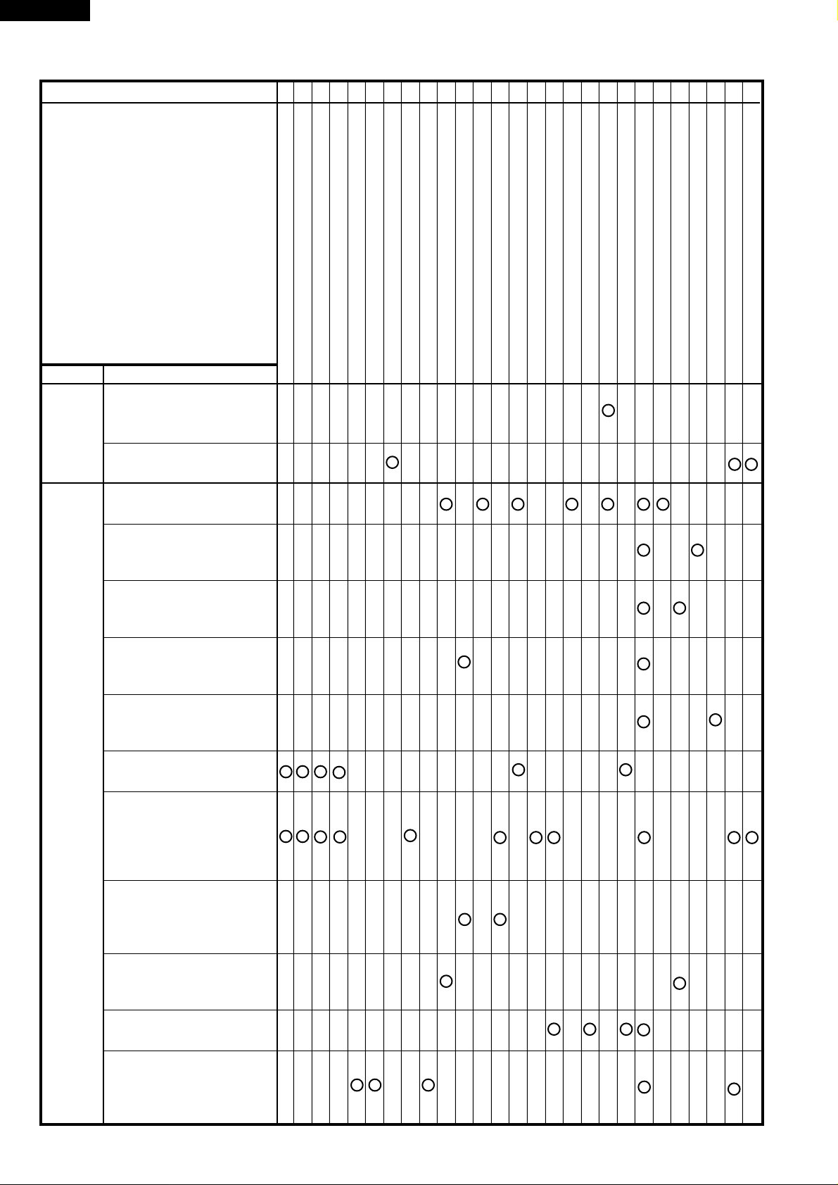
CONDITION
OFF
CONDITION
TEST PROCEDURE
POSSIBLE CAUSE
AND
DEFECTIVE PARTS
PROBLEM
Home fuse or breaker blows
when power cord is plugged
into wall outlet.
Fuse (F1) F6.3A blows when
the door is opened.
Oven does not operate at
all.
ABCDEEEEE FG G GH I JKL M M N
MAGNETRON
HIGH VOLTAGE TRANSFORMER
RECTIFIER ASSEMBLY
H.V. CAPACITOR
PRIMARY LATCH SWITCH
2ND LATCH SWITCH
MONIOTR SWITCH
3RD LATCH SWITCH
COOK SWITCH
THERMAL CUT-OUT 125˚C
TIMER MOTOR
TIMER CONTACT
TIMER VAR. SWITCH
SPECIAL FUSE
FUSE 6.3A
SURGE RELAY RY2
NOISE FILTER
SURGE RESISTOR
POWER SUPPLY CORD
SHORTED WIRE HARNESS
OPENED WIRE HARNESS
WALL OUTLET
FAN MOTOR
OVEN LAMP OR SOCKET
TURNTABLE MOTOR
MISADJUSTMENT SWITCH
RELAY RY1
COOKING
CONDITION
Heat is produced in oven
load but oven lamp does not
light.
Heat is produced in oven
load but fan motor does not
operate.
Heat is produced in oven
load but timer motor does
not operate.
Heat is produced in oven
load but turn-table motor
does not operate.
Oven stops as soon as the
oven is started.
Oven seems to be operating
but little or no heat is produced in oven load. (Variable cooking control is set at
"HIGH" position).
Oven does not operate properly in any other position except "HIGH" position. (Oven
operate properly at HIGH).
Oven goes into cook cycle,
but shuts down before end
of cycle.
Home fuse or breaker blows
when the oven is started
Oven lamp lights but the
other electrical parts do not
operate.
8
Page 11

PROCEDURE
A MAGNETRON TEST
R-5L16
TEST PROCEDURES
LETTER
COMPONENT TEST
NEVER TOUCH ANY PART IN THE CIRCUIT WITH YOUR HAND OR AN INSULATED TOOL
WHILE THE OVEN IS IN OPERATION.
CARRY OUT 3D CHECK
Isolate the magnetron from high voltage circuit by removing all leads connected to filament terminal.
To test for an open circuit filament use an ohmmeter to make a continuity test between the magnetron
filament terminals, the meter should show a reading of less than 1 ohm.
To test for short filament to anode condition, connect ohmmeter between one of the filament terminals
and the case of the magnetron (ground). This test should be indicated an infinite resistance. If a low or
zero resistance reading is obtained then the magnetron should be replaced.
MICROWAVE OUTPUT POWER (IEC-705-1988)
The following test procedure should be carried out with the microwave oven in a fully assembled
condition (outer case fitted). Microwave output power from the magnetron can be measured by way of
IEC 705, i.e. it can be measured by using water load how much it can be absorbed by the water load.
To measure the microwave output power in the microwave oven, the relation of calorie and watt is used.
When P(W) heating works for t(second), approximately P x t/4.187 calorie is generated. On the other
hand, if the temperature of the water with V(ml) rises ∆T (°C) during this microwave heating period, the
calorie of the water is V x ∆T.
The formula is as follows;
P x t / 4.187 = V x ∆ T P (W) = 4.187 x V x ∆T / t
Our condition for water load is as follows:
Room temperature ........... around 20°C Power supply Voltage.......... .Rated voltage
Water load ....... 1000 g Initial temperature...... 10±2°C Heating time.......... 42 sec.
P = 100 x VT
Measuring condition:
1. Container
The water container must be a cylindrical borosilicate glass vessel having a maximum material
thickness of 3 mm and an outside diameter of approximately 190 mm.
2. Temperature of the oven and vessel
The oven and the empty vessel are at ambient temperature prior to the start the test.
3. Temperature of the water
The initial temperature of the water is (10±2)°C.
4. Select the initial and final water temperature so that the maximum difference between the final water
temperature and the ambient temperature is 5K.
5. Select stirring devices and measuring instruments in order to minimize addition or removal of heat.
6. The graduation of the thermometer must be scaled by 0.1°C at minimum and accurate thermometer.
7. The water load must be (1000±5) g.
8. “t” is measured while the microwave generator is operating at full power. Magnetron filament heatup time is not included.
NOTE:The operation time of the microwave oven is “t + 2” sec. 2 sec. is magnetron filament heat-up time.
Measuring method:
1. Measure the initial temperature of the water before the water is added to the vessel.
(Example: The initial temperature T1 = 11°C)
2. Add the 1 litre water to the vessel.
3. Place the load on the centre of the shelf.
4. Operate the microwave oven at HIGH for the temperature of the water rises by a value ∆ T of
(10 ± 2) K.
5. Stir the water to equalize temperature throughout the vessel.
6. Measure the final water temperature. (Example: The final temperature T2 = 21°C)
7. Calculate the microwave power output
P in watts from above formula.
9
Page 12

R-5L16
PROCEDURE
TEST PROCEDURES (CONT'D)
LETTER
COMPONENT TEST
Initial temperature ......................................................................................................... T1 = 11°C
Temperature after (42 + 3) = 45 sec. ............................................................................ T2 = 21°C
Temperature difference Cold-Warm............................................................................ ∆T1 = 10°C
Measured output power
The equation is “P = 100 x ∆T” ........................................................ P = 100 x 10°C = 1000 Watts
JUDGMENT: The measured output power should be at least
CAUTION: 1°C CORRESPONDS TO 100 WATTS. REPEAT MEASUREMENT IF THE POWER IS
INSUFFICIENT.
1000g
1000g
T1˚C
Heat up for 45 sec.
B HIGH VOLTAGE TRANSFORMER TEST
WARNING: High voltages and large currents are present at the secondary winding and
filament winding transformer. It is very dangerous to work near this part when
the oven is on. NEVER make any voltage measurements of the high-voltage
circuits, including the magnetron filament.
CARRY OUT 3D CHECKS
Disconnect the leads to the primary winding of the high voltage transformer. Disconnect the filament and
secondary winding connections from the rest of the HV circuitry. Using an ohmmeter, set on a low range,
it is possible to check the continuity of all three windings. The following readings should be obtained:-
± 15 % of the rated output power.
1000g
T2˚C
a. Primary winding .....................1.4 Ω approximately
b. Secondary winding.................82 Ω approximately
c. Filament winding .................... less than 1 Ω
If the reading obtained are not stated above, then the high voltage transformer is probably faulty and
should be replaced.
CARRY OUT
4R CHECKS
C HIGH VOLTAGE RECTIFIER ASSEMBLY TEST
HIGH VOLTAGE RECTIFIER TEST
CARRY OUT
3D CHECKS.
Isolate the high voltage rectifier assembly from the HV circuit. The high voltage rectifier can be tested
using an ohmmeter set to its highest range. Connect the ohmmeter across the terminal B+C of the high
voltage rectifier and note the reading obtained. Reverse the meter leads and note this second reading.
The normal resistance is infinite in one direction and more than 100 kΩ in the other direction.
CARRY OUT
4R CHECKS
ASYMMETRIC RECTIFIER TEST
CARRY OUT
3D CHECKS.
AB
D2 D1
ASYMMETRIC
RECTIFIER
HIGH VOLTAGE RECTIFIER
C
10
Page 13

TEST PROCEDURES (CONT'D)
PROCEDURE
LETTER COMPONENT TEST
Isolate the high voltage rectifier assembly from the HV circuit. The asymmetric can be tested using an
ohmmeter set to its highest range across the terminals A+B of the asymmetric rectifier and note the
reading obtained. Reverse the meter leads and note this second reading. If an open circuit is indicated
in both direction then the asymmetric rectifier is good. If an asymmetric rectifier is shorted in either
direction, then the asymmetric rectifier is probably faulty and must be replaced with high voltage rectifier.
When the asymmetric rectifier is defective, check whether magnetron, high voltage rectifier, high voltage
wire or filament winding of the high voltage transformer is shorted.
R-5L16
CARRY OUT
4R CHECKS
NOTE: FOR MEASUREMENT OF THE RESISTANCE OF THE RECTIFIER, THE BATTERIES OF THE
MEASURING INSTRUMENT MUST HAVE A VOLTAGE AT LEAST 6 VOLTS, BECAUSE
OTHERWISE AN INFINITE RESISTANCE MIGHT BE SHOWN IN BOTH DIRECTIONS.
D HIGH VOLTAGE CAPACITOR TEST
CARRY OUT
3D CHECKS
A. Isolate the high voltage capacitor from the circuit.
B. Continuity check must be carried out with measuring instrument which is set to the highest resistance
range.
C. A normal capacitor shows continuity for a short time (kick) and then a resistance of about 10MΩ after
it has been charged.
D. A short-circuited capacitor shows continuity all the time.
E. An open capacitor constantly shows a resistance about 10 MΩ because of its internal 10MΩ
resistance.
F. When the internal wire is opened in the high voltage capacitor shows an infinite resistance.
G. The resistance across all the terminals and the chassis must be infinite when the capacitor is normal.
If incorrect reading are obtained, the high voltage capacitor must be replaced.
CARRY OUT
4R CHECKS
E SWITCH TEST
Isolate the switch to be tested and using an ohmmeter check between the terminals as described in the
following table.
CARRY OUT
3D CHECKS
Plunger Operation COM to NO COM to NC
Released O.C. S.C.
Depressed S.C. O.C.
COM; Common terminal, NO; Normally open terminal NC; Normally close terminal
S.C.; Short, O.C.; Open circuit
If incorrect readings are obtained, make the necessary switch or replace the switch.
CARRY OUT
4R CHECKS.
F THERMAL CUT OUT TEST
CARRY OUT
3D CHECKS
Disconnect the leads from the terminals of the thermal cut-out. Then using an ohmmeter, make a
continuity test across the two terminals as described below.
CARRY OUT
4R CHECKS
Temperature of "ON" condition (closed circuit)........................................... This is not resetable type
Temperature of "OFF" condition (open circuit)............................................................... Above 125°C
Indication of ohmmeter (When room temperature is approx. 20°C.) ............................ Closed circuit
If incorrect readings are obtained, replace the thermal cut-out.
An open circuit thermal cut-out (MG) indicates that the magnetron has overheated, this may be due to
restricted ventilation, cooling fan failure or a fault condition within the magnetron or HV circuit.
Table: Terminal Connection of Switch
11
Page 14

R-5L16
PROCEDURE
LETTER
G TIMER MOTOR (WITH VARI-SWITCH) TEST
TEST PROCEDURES (CONT'D)
COMPONENT TEST
An open circuit thermal cut-out (OVEN) indicates that the foods in the oven may catch fire, this may be
due to over heating produced by improper setting of the cooking timer or failure of the control panel.
CARRY OUT
3D CHECKS before any of the following timer tests.
TIMER SWITCH- CONTACTS
Disconnect the leads from terminals described at following table. Connect an ohmmeter across terminals
described at following table. Advance the timer and check that a short circuit reading is obtained on the
meter. Turn the timer back to the zero (0) position and check that an open circuit reading is obtained on
the meter. If these readings are not obtained then replace the timer.
Disconnecting and checking terminals 1 and 2
TIMER - MOTOR
Disconnect the leads from terminals described at following table. Connect an ohmmeter across the timer
motor winding, terminals are described at following table, and check that a reading of resistance
described at following table is indicated. If this reading is not obtained then the timer is probably defective
and should be replaced. (Also refer to test procedure N.)
Disconnecting and checking terminals 5 and 6
Resistance of motor winding approximately 34.2 kohms
CARRY OUT
4R CHECKS after any of the above tests.
VARI SWITCH - CONTACTS
Before proceeding with this part of the test, check the relay coil as outlined above.
WARNING: This test requires the oven to be operated with supply connected.
Follow the instruction below carefully.
1. CARRY OUT
3D CHECKS
2. Disconnect the leads to the primary of the high voltage transformer. Make sure that the leads remain
isolated from other oven components and chassis.
3. Disconnect the leads from terminals 3 and 4 of the timer, make sure that these leads remain isolated
from other components and the oven chassis (use insulation tape if necessary). Do not disconnect
leads from terminals 5 and 6.
4. Securely clip the leads of an ohmmeter across terminals 3 and 4 of the timer. (Make sure the meter
can be read easily without being touched during the test.)
5. Close the door of the oven.
6. Connect the supply.
7. Set the TIMER to several minutes.
8. Without touching the meter or any part of the oven make a note of the time which the ohmmeter
indicates Short and Open circuit in each power level as described in the table.
9. Set the MICROWAVE TIMER to 0 (zero).
10. CARRY OUT
3D CHECKS
11. Disconnect ohmmeter lead from terminal 4 of the timer.
12. Reconnect the lead of the panel harness to the terminal 4 of the timer.
13. Disconnect the lead from contact
14. Clip the lead of an ohmmeter to contact
NC of vari switch.
NC of vari switch.
15. Repeat steps 5, 6, 7, 8, 9 and 10.
But in this time, the ohmmeter must indicate Short and Open circuit reversely against the table.
16. Disconnect ohmmeter leads from terminals 3 of the timer and contacts
NC of vari switch.
17. Reconnect the leads to the primary of the high voltage transformer.
12
Page 15

PROCEDURE
LETTER
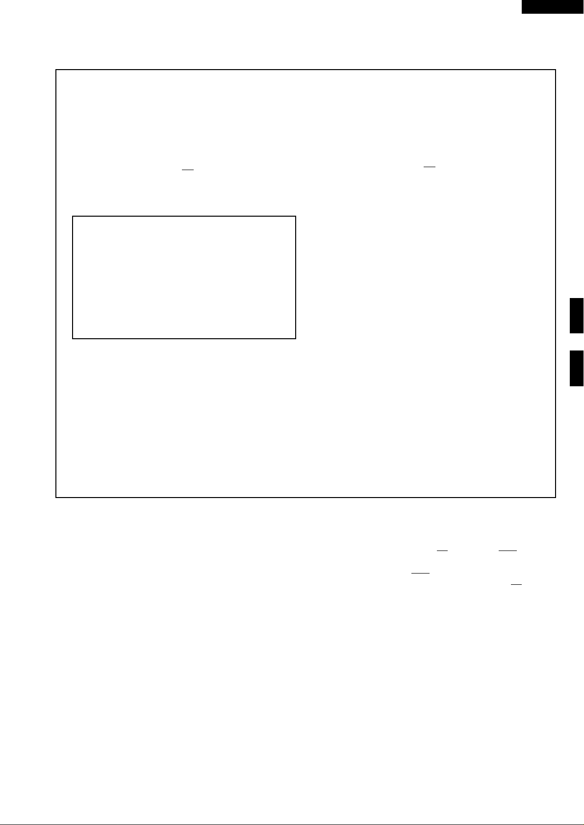
H BLOWN SPECIAL FUSE F2
R-5L16
TEST PROCEDURES (CONT'D)
COMPONENT TEST
VARI-MODE ON TIME OFF TIME
HIGH 26.4 sec 0 sec.
(approx. 100% power)
MEDIUM HIGH 20.4 sec 6 sec.
(approx. 70% power)
MEDIUM 14.5 sec 11.9 sec.
(approx. 50% power)
MEDIUM LOW 8.6 sec 17.8 sec.
(approx. 30% power)
LOW 4.4 sec 22 sec.
(approx. 10% power)
6
1
3
M
Vari switch
Timer motor with vari switch
5
2
4
ON: Meter indicates closed. OFF: Meter indicates open.
Check results: If any of the condition as described in the table are not obtained at step 8, or the ohmmeter
does not indicate reverse conditions against the table, then the timer should be re-placed.
CARRY OUT
4R CHECKS
CARRY OUT 3D CHECKS
1. If the special fuse F2 is blown, there could be shorts or grounds in electrical parts or wire harness. Check
them and replace the defective parts or repair the wire harness.
2. If the special fuse
F2 is blown, there could be a short in the asymmetric rectifier or there is a ground
in wire harness. A short in the asymmetric rectifier may have occurred due to short or ground in H.V.
rectifier, magnetron, high voltage transformer or H.V. wire. Check them and replace the defective
parts or repair the wire harness.
CARRY OUT
4R CHECKS
CAUTION: Only replace special fuse
I BLOWN FUSE Fl F6.3A
CARRY OUT 3D CHECKS
1. If the fuse
F1 F6.3A is blown when the door is opened, check the relay RY1, monitor switch and
monitor resistor. If the fuse
switch(es) and the fuse
2. If the fuse
F1 6.3A is blown, there could be shorts or ground in electrical parts or wire harness. Check
them and replace the defective parts or repair the wire harness.
CARRY OUT
4R CHECKS
CAUTION: Only replace fuse with the correct value replacement.
J SURGE RELAY TEST
CARRY OUT
3D CHECKS
Disconnect the leads to terminals 1 and 2. Connect an ohmmeter across the terminals 1 and 2, a reading
of approximately 15 kohms should be indicated. If this is not the case then the relay coil is probably faulty
and the relay should be replaced.
F2 with the correct value replacement
F1 F6.3A is blown by incorrect door switching replace the defective
F1 F6.3A.
CARRY OUT
Relay contact test for short circuit:
CARRY OUT
4R CHECKS
3D CHECKS
4
2
COIL
5
1
Isolate terminals 1 and 2, 4 and 5 of the relay. Using an ohmmeter, check continuity between terminal
4 and 5. A reading of infinite resistance should be obtained. If this is not the case then the relay is probably
faulty and should be replaced.
CARRY OUT
4R CHECKS
13
Page 16

R-5L16
PROCEDURE
LETTER
K NOISE FILTER TEST
TEST PROCEDURES (CONT'D)
COMPONENT TEST
N
L
WHT
CARRY OUT
3D CHECKS
Disconnect the leads from the terminals of noise filter.
Using an ohmmeter, check between the terminals as described in the following table.
MEASURING POINTS INDICATION OF OHMMETER
Between N and L Open circuit
Between terminal N and WHITE Short circuit
Between terminal L and RED Short circuit
If incorrect readings are absorbed, replace the noise filter unit.
CARRY OUT
4R CHECKS
L MONITOR RESISTOR AND SURGE RESISTOR TEST
CARRY OUT
3D CHECKS
Disconnect the leads from the monitor resistor or surge resistor.
Using an ohmmeter and set on a low range.
Check between the terminals of the monitor resistor or surge as described in the following table.
Table: Resistance
Resistor Resistance
Monitor resistor Approx. 4.3Ω
Surge resistor Approx. 10Ω
F6.3A
L
Cx
L
RED
Cy
L (min) Cx ± 20% Cy ± 20%
1.0mH 0.22µF 0.0033µF
If incorrect readings are obtained, replace the monitor resistor or surge resistor
CARRY OUT
4R CHECKS
M MOTOR WINDING TEST
CARRY OUT
3D CHECKS
Disconnect the leads from the motor. Using an ohmmeter, check the resistance between the two
terminals as described in the table below.
Fan motor Approximately 186 ohms
Turntable motor Approximately 16 kohms
If incorrect readings are obtained, replace the motor.
CARRY OUT
4R CHECKS
N RELAY TEST
CARRY OUT 3D CHECKS
Disconnect the leads to terminals A1 and A2. Connect an ohmmeter across the terminals A1 and A2, a
reading of approximately 1.7 kohms should be indicated. If this is not the case then the relay coil is
probably faulty and the relay should be replaced.
CARRY OUT
4R CHECKS
Relay contact test for short circuit:
CARRY OUT
3D CHECKS
Isolate terminals A1 and A2, 1, 2, 5 and 6 of the relay. Using an ohmmeter,
check continuity between terminals 1 and 2 and between terminal 5 and 6.
A reading of infinite resistance should be obtained. If this is not the case
then the relay is probably faulty and should be replaced.
CARRY OUT
4R CHECKS
Table: Resistance of Motor
Motors Resistance
A1
COIL
5
3
1
A2
6
4
2
RELAY
14
Page 17

R-5L16
COMPONENT REPLACEMENT AND ADJUSTMENT PROCEDURE
WARNING: Avoid possible exposure to microwave energy. Please follow the instructions below before operating
the oven.
1. CARRY OUT 3D CHECKS.
2. Make sure that a definite” click” can be heard when the
microwave oven door is unlatched. (Hold the door in a
closed position with one hand, then push the door open
button with the other, this causes the latch leads to rise,
it is then possible to hear a “click’ as the door switches
operate.)
3. Visually check the door and cavity face plate for damage
(dents, cracks, signs of arcing etc.).
Carry out any remedial work that is necessary before operating the oven.
Do not operate the oven if any of the following conditions
exist;
Please refer to ‘OVEN PARTS, CABINET PARTS, DOOR PARTS’, when carrying out any of the following removal procedures:
1. Door does not close firmly.
2. Door hinge, support or latch hook is damaged.
3. The door gasket or seal or damaged.
4. The door is bent or warped.
5. There are defective parts in the door interlock system.
6. There are defective parts in the microwave generating
and transmission assembly.
7. There is visible damage to the oven.
Do not operate the oven:
1. Without the RF gasket (Magnetron).
2. If the wave guide or oven cavity are not intact.
3. If the door is not closed.
4. If the outer case (cabinet) is not fitted.
OUTER CASE REMOVAL
To remove the outer case proceed as follows.
1. Disconnect oven from power supply.
2. Open the oven door and wedge it open.
3. Remove the screws from rear and along the side edge of
case.
4. Slide the entire case back about 3cm to free it from
retaining clips on the cavity face plate.
5. Lift the entire case from the oven.
6. Discharge the H.V. capacitor before carrying out any
further work.
7. Do not operate the oven with the outer case removed.
N.B.; Step 1, 2 and 6 form the basis of the 3D checks.
CAUTION: DISCHARGE HIGH VOLTAGE CAPACI-
TOR BEFORE TOUCHING ANY OVEN
COMPONENT OR WIRING.
HIGH VOLTAGE COMPONENTS REMOVAL
(HIGH VOLTAGE CAPACITOR AND HIGH VOLTAGE RECTIFIER ASSEMBLY)
To remove the components, proceed as follows.
1. CARRY OUT
2. Disconnect all the leads and terminals of high voltage
rectifier assembly from high voltage capacitor.
3. Remove one (1 ) screw holding earth side terminal of high
voltage rectifier assembly, and remove capacitor holder.
4. Remove one (1 ) screw holding capacitor holder to the
oven cavity.
5. Release the capacitor holder from the duct.
6. Remove the capacitor from the capacitor holder.
3D CHECKS
HIGH VOLTAGE TRANSFORMER REMOVAL
1. CARRY OUT
2. Disconnect the filament leads of the high voltage
transformer from high voltage capacitor and the
magnetron.
3. Disconnect the H.V. wire A from the high voltage
3D CHECKS
MAGNETRON REMOVAL
1. CARRY OUT 3D CHECKS
2. Remove the air separate duct B from the chassis support
and the air intake duct.
3. Disconnect the H.V. wire B and filament lead of the
transformer from the magnetron
4. Remove this one (1 ) screw holding the chassis support
5. Remove the one (1) screw holding the chassis support to
the oven back plate.
7. Now high voltage rectifier assembly and capacitor should
be free.
CAUTION: WHEN REPLACING HIGH VOLTAGE
RECTIFIER ASSEMBLY, ENSURE THAT
THE CATHODE (EARTH) CONNECTION
IS SECURELY FIXED TO THE CAPACITOR HOLDER WITH AN EARTHING
SCREW.
transformer
4. Remove the two (2) screws and one (1) washer holding
the transformer to base plate.
5. Remove the transformer.
6. Now, the high voltage transformer is free.
6. Remove the one (1) screw holding the chassis support to
the magnetron.
7. Unclip the noise unit from the fan duct and lift the chassis
support.
8. Unclip the air separator duct from the fan duct and
remove the air separator duct to the magnetron.
9. Move the air intake duct to left
10.Remove the air deflector from the magnetron.
15
Page 18

R-5L16
11. Carefully remove four (4) screws holding magnetron to
waveguide, when removing the screws hold the
magnetron to prevent it from falling.
12.Remove the magnetron from the waveguide with care so
the magnetron antenna is not hit by any metal object
around the antenna
FAN MOTOR REMOVAL
1. CARRY OUT ONE 3D CHECKS.
2. Remove the (1 ) screw holding the noise filter to the
chassis support
3. Release the noise filter from the tabs of the fan duct.
4. Disconnect the wire leads from the fan motor.
5. Remove the one (1) screw holding the capacitor holder to
the oven cavity back plate.
CONTROL PANEL REMOVAL
1. CARRY OUT
2. Disconnect the main harness from the timer motor and
the cook switch.
3. Remove the one (1) screw holding the control panel to the
3D CHECKS
TURNTABLE MOTOR REMOVAL
13.Remove the magnetron cushion from the magnetron.
CAUTION: WHEN REPLACING THE MAGNETRON,
BE SURE THE R.F. GASKET IS IN PLACE
AND THE MAGNETRON MOUNTING
SCREWS ARE TIGHTENED SECURELY.
6. Release the tabs of the capacitor holder from the fan
duct.
7. Remove the fan duct from the oven.
8. Remove the fan blade assembly from the fan motor.
9. Remove the two (2) screws and two (2) nuts holding the
fan motor to the fan duct.
10.Now, the fan motor is free.
oven cavity.
4. Lift up the control panel assembly and pull it forward.
Now, the control panel assembly is free.
1. Disconnect the oven from power supply.
2. Remove the turntable motor cover by snipping of material
in four corners.
3. Where the corners have been snipped off bend corner
areas flat. No sharp edge must be evident after removal
of TT motor cover.
TURNTABLE COUPLING REMOVAL
1. Remove the turntable motor, refer to "Turntable Motor
Removal".
2. Pull the coupling out of the hole in the oven cavity.
3. At that time the turntable coupling will be free.
CAUTION: REPLACE THE PACKING AT THE SAME
TIME WHEN REPLACING THE COUPLING. BECAUSE THE PACKING MAY
BE INJURED BY PULLING OUT THE
COUPLING.
OVEN LAMP SOCKET REMOVAL
1. CARRY OUT 3D CHECKS
2. Pull the wire leads from the oven lamp socket by pushing
the terminal hole of the oven lamp socket with the flat type
small screw driver.
3. Lift up the oven lamp socket.
4. Now, the oven lamp socket is free.
4. Disconnect the wire lead from turntable motor and remove
the 2 screws holding the turntable motor.
5. Turntable is now free.
6. After replacement use the one (1) screw allocated to fit
the TT motor cover.
COUPLING
PACKING
T.T.M.
SUPPORT
ANGLE
Figure C-1 Turntable Coupling
Oven lamp
socket
Terminal
Wire lead
Flat type small
screw driver
Terminal hole
16
Figure C-2 Oven lamp socket
Page 19

POWER SUPPLY CORD REPLACEMENT
TAB
MONITOR
SWITCH
3RD. LATCH
SWITCH
PRIMARY
LATCH SWITCH
TAB
2ND. LATCH
SWITCH
R-5L16
Removal
1. CARRY OUT
3D CHECKS.
2. Remove the single (1) screw holding the green/yellow
wire to the chassis support.
3. Disconnect the leads of the power supply cord from the
noise filter, referring to the Figure C-3 (a).
4. Release the power supply cord from the rear cabinet.
5. Now, the power supply cord is free.
OVEN CAVITY
PLATE
BROWN WIRE
BLUE WIRE
NOISE FILTER
POWER SUPPLY CORD
CHASSIS SUPPORT
Figure C-3 (a) Replacement of Power Supply Cord
Re-install
1. Insert the moulding cord stopper of power supply cord
into the square hole of the rear cabinet, referring to the
Figure C-3 (b). Installation of Power supply cord.
2. Install the earth wire lead of power supply cord to the rear
cabinet with one (1) screw and tight the screw.
3. Connect the brown and blue wire leads of power supply
cord to the noise filter correctly, referring to the Pictorial
Diagram.
POWER SUPPLY
CORD
MOULDING
CORD
STOPPER
OVEN CAVITY
BACK PLATE
SQUARE HOLE
Figure C-3 (a) Replacement of Power Supply Cord
PRIMARY LATCH SWITCH, 2ND LATCH SWITCH, 3RD LATCH SWITCH AND MONITOR SWITCH REMOVAL
1. CARRY OUT 3D CHECKS.
2. Remove the control panel assembly referring to
"CONTROL PANEL REMOVAL”.
3. Disconnect the leads from all switches.
4. Remove the two (2) screws holding the latch hook to the
oven cavity.
5. Remove the latch hook.
6. Push the retaining tab slightly and remove the switch.
Figure C-4. Switches
PRIMARY LATCH SWITCH, 2ND LATCH SWITCH, 3RD LATCH SWITCH AND MONITOR SWITCH ADJUSTMENT
If the primary latch switch, 2nd. Iatch switch, 3rd latch switch
and monitor switch do not operate properly due to a misadjustment, the following adjustment should be made.
1. CARRY OUT
3D CHECKS
2. Loosen the two (2) screws holding the latch hook to the
oven cavity front flange.
3. With door closed, adjust the latch hook by moving it back
and forward, or up and down. In and out play of the door
allowed by the latch hook should be less than 0.5 mm.
The horizontal position of the latch hook should be placed
where the 2nd, latch switch and the monitor switch have
activated with the door closed.
The vertical position of the latch hook should be placed
where the primary latch switch and 3rd latch switch have
activated with the door closed.
4. Secure the screws with washers firmly.
5. Make sure of the primary, 2nd latch, 3rd latch switches,
and monitor switch operation. If those switches have not
activated with the door closed, two (2) screws holding
17
Page 20

R-5L16
latch hook to oven cavity front flange and adjust the latch
hook position.
After adjustment, make sure of following:
1. In and out play of door remains less than 0.5 mm when
latched position. First check latch hook position, pushing
and pulling the door toward the oven face. The results
(play of the door) should be less than 0.5mm.
2. The contacts (COM-NO) of primary latch switch and 3rd
latch switch interrupt the circuit before the door can be
opened.
3. The contacts (COM-NC) of the monitor switch close and
the contacts (COM-NO) of the 2nd latch switch open
when the door is opened.
4. Re-install outer case and check for microwave leakage
around the door with an approved micro-wave survey
meter. (Refer to Microwave Measure-ment Procedure.)
DOOR FRAME AND SCREEN REMOVAL
2ND. LATCH
LATCH HOOK
LATCH
HEADS
DOOR OPEN BUTTON
SWITCH
PRIMARY
LATCH SWITCH
MONITOR
SWITCH
3RD. LATCH
SWITCH
OPEN LEVER
Figure C-5 Latch Switches Adjustment
Remove the door assembly, referring to from item 1 through
item 4 of "DOOR REPLACEMENT”.
1. Place the door assembly on a soft cloth with facing up
2. Remove the choke cover, referring to "CHOKE COVER
REMOVAL".
3. Remove the four (4) screws holding the door frame to the
door panel assembly.
4. Release the door frame from the door panel assembly.
5. Remove the upper and lower door sush by making their
DOOR REPLACEMENT AND ADJUSTMENT
DOOR REPLACEMENT
1. CARRY OUT
2. Remove five (5) screws holding the upper and lower oven
hinge to the oven cavity. The lower oven hinge is now
free.
3. Remove door assembly with upper oven hinge by pulling
it forward.
4. Separate the door assembly and upper oven hinge. Door
assembly is now free.
5. Re-install upper oven hinge to the new door assembly.
6. On re-installing new door assembly, secure the upper
and lower oven hinges with the five (5) mounting screws
to the oven cavity. Make sure the door is parallel with
bottom line of the oven face plate and the latch head pass
through the latch holes correctly.
7. CARRY OUT
Note: After any service to the door, the approved microwave
survey meter should be used to assure in compliance
with proper microwave radiation standards. (Refer
to Microwave Measurement Procedure.)
3D CHECKS
4R CHECKS
tabs straight.
6. Gently prise apart the screen from the frame.
7. Peel the tape using steady pressure which will allow the
screen to be separated from the door.
Note: Care is needed when peeling away the tape, as
excessive force may damage the screen. Do not
lever the components apart, as this may cause
damage to the screen print.
DOOR ADJUSTMENT
When removing and/or loosening hinges such as in door
replacement, the following adjustment criteria are taken.
Door is adjusted to meet the following three conditions by
keeping screws of hinge loose.
1. Adjust door latch heads at a position where they smoothly
catch the latch hook through the latch holes. Refer to
latch switch adjustments.
2. Deviation of the door alignment from horizontal line of
cavity face plate is to be less than 1.0mm.
3. The door is positioned with its face depressed toward the
cavity face plate.
4. Reinstall outer case and check for microwave leakage
around the door with an approved microwave survey
meter. (Refer to Microwave Measurement Procedure.)
LATCH HEAD REMOVAL
1. Remove door choke, use about 0.5 mm steel plate or
small flat type screw driver.
18
Page 21

R-5L16
2. Remove fasteners positioned behind choke.
3. Release door frame plastic clips by levering towards door
centre, while applying a gentle force to remove frame.
4. Remove latch spring and slide out latch head.
Reassemble parts, the door frame can be snapped together
before assembling fasteners and choke.
UPPER OVEN HINGE
DOOR ASSEMBLY
LATCH HEADS
LOWER
OVEN HINGE
Figure C-6. Door Assembly Replacement and
Adjustment
CHOKE COVER REMOVAL
1. Insert an iron plate (thickness of about 0.5mm) or flat type
screw driver to the gap between the choke cover and
door panel as shown figure to free the engaging part. The
protect sheet may be used not to damage the door panel.
Lift up the choke cover, now choke cove is free.
FLATE TYPE
SCREW DRIVER
PROTECT BY TAPE
FLATE TYPE
SCREW DRIVER
DOOR FILM
Removal
1. Tear the door film from the door panel.
2. Now, the door film is free.
Installation
1. Put the adhesive tape on the backing film of the door film
as shown in Fig. 8.
2. Tear the backing film by pulling the adhesive tape.
3. Put the pasted side of the door film on the door panel.
Figure C-8 Door Film
Figure C-7 Choke Cover Removal
Sealer film
Backing film
Adhesive tape
19
Page 22

R-5L16
MICROWAVE MEASUREMENT
After adjustment of door latch switches, monitor switch
and doorare completed individually or collectively, the following leakage test must be performed with a survey instrument and it must be confirmed that the result meets the
requirements of the performance standard for microwave
oven.
REQUIREMENT
The safety switch must prevent microwave radiation emis-
2
sion in excess of 5mW/cm
at any point 5cm or more from
external surface ofthe oven.
PREPARATION FOR TESTING:
Before beginning the actual test for leakage, proceed as
follows;
1. Make sure that the test instrument is operating normally
as specified in its instruction booklet.
Important:
Survey instruments that comply with the requirement for
instrumentations as prescribed by the performance
standard for microwave ovens must be used for testing.
Recommended instruments are:
NARDA 8100
NARDA 8200
HOLADAY HI 1500
SIMPSON 380M
2. Place the oven tray into the oven cavity.
3. Place the load of 275 ± 15ml of water initially at 20 ±
5˚C in the center of the oven tray. The water container
should be a low form of 600 ml beaker with inside
diameter of approx. 8.5cm and made of an electrically
non-conductive material such as glass or plastic.
The placing of this standard load in the oven is important
not only to protect the oven, but also to insure that any
leakage is measured accurately.
4. Close the door and turn the oven ON with the timer set for
several minutes. If the water begins to boil before the
survey is completed, replace it with 275ml of cool water.
5. Move the probe slowly (not faster that 2.5cm/sec.)
along the gap.
6. The microwave radiation emission should be measured
at any point of 5cm or more from the external surface of
the oven.
mW cm
mW cm
SHARP
2
2
Microwave leakage measurement at 5 cm distance
20
Page 23

TEST DATA AT A GLANCE
Parts Symbol Value / Data R-2V15
Fuse F1 F6.3A/250V
Special fuse F2 F10A/250V
Monitor resistor R1 4.3Ω 20W
Surge resistor R2 10Ω 20W
Thermal cut-out (MG) TC1 125°C
Thermal cut-out (OVEN) TC2 125°C
Relay RY1 Approx. 1.7kΩ
Surge relay RY2 Approx. 15kΩ
Oven lamp OL 230 V 25W E14
High voltage capacitor C 1.2µF AC 2100V
Magnetron MG Filament < 1Ω
Filament – chassis ∞ ohm.
High voltage transformer T Filament winding < 1Ω
Secondary winding Approx. 82Ω
Primary winding Approx. 1.4Ω
R-5L16
21
Page 24

R-5L16
NOTE: CONDITION OF OVEN
SCHEMATIC
1. DOOR CLOSED
2. TIMER KNOB AT "
F2:F10A
SPECIAL
FUSE
220-230V~50Hz
G-Y
EARTH
BLU BRN
0.22 µ/250V
NL
" POSITION
10M/0.5W
180K/0.5W
NOISE SUPPRESSION COIL
NOISE
FILTER
TC2: THERMAL
0.0033µ/250V
0.0033µ/250V
TC1: THERMAL
NC
TIMER
SWITCH
CUT-OUT
125˚C(OVEN)
SW5:
MONITOR
SWITCH
R1:
MONITOR
RESISTOR
CUT-OUT
125˚C (MAG.)
4.3/20W
OVEN LAMP
OL
SW1:
PRIMARY
LATCH
SWITCH
SW2:
2ND.
LATCH
SW4:
TM
TIMER
SWITCH
COOK
SWITCH
FM
FAN MOTOR
VARI.
SWITCH
RY1
TTM
TURNTABLE
MOTOR
Figure O-1 Oven Schematic-OFF Condition
RY2:
SURGE
RELAY
F1: FUSE
F6.3A
SURGE
RELAY
CONTACT
SW3:
3RD.
R2:
SURGE
T:
LATCH
SWITCH
RESISTOR
10/20W
HIGH VOLTADE
TRANSFORMER
C:
CAPACITOR
1.2µ
2100V AC.
ASYMMETRIC
RECTIFIER
MG: MAGNETRON
H.V. RECTIFIER
NOTE: CONDITION OF OVEN
SCHEMATIC
1. DOOR CLOSED
2. MICROWAVE POWER CONTROL
"HIGH"
3. TIMER ON
4. COOK SWITCH PUSHED
F2: F10A
SPECIAL
FUSE
10M/0.5W
220-230V~50Hz
G-Y
EARTH
BLU BRN
0.22 µ/250V
NL
NOISE SUPPRESSION COIL
NOISE
FILTER
0.0033µ/250V
180K/0.5W
0.0033µ/250V
TC2: THERMAL
CUT-OUT
125˚C(OVEN)
SW5:
R1:
TC1: THERMAL
CUT-OUT
125˚C (MAG.)
TIMER
SWITCH
MONITOR
SWITCH
MONITOR
RESISTOR
4.3/20W
SW1:
PRIMARY
OL
OVEN LAMP
LATCH
SWITCH
SW2:
2ND.
NC
LATCH
SWITCH
TM
SW4:
COOK
TIMER
SWITCH
TTM
FM
FAN MOTOR
VARI.
SWITCH
RY1
TURNTABLE
MOTOR
RY2:
SURGE
RELAY
F1: FUSE
F6.3A
SURGE
RELAY
CONTACT
SW3:
3RD.
R2:
SURGE
T:
LATCH
SWITCH
RESISTOR
10/20W
HIGH VOLTADE
TRANSFORMER
C:
CAPACITOR
1.2µ
2100V AC.
ASYMMETRIC
RECTIFIER
MG: MAGNETRON
H.V. RECTIFIER
Figure O-2 Oven Schematic-ON Condition
22
Page 25

R-5L16
1
A
POWER SUPPLY CORD
BLU
BRN
B
NOISE
FILTER
L
N
F2: SPECIAL FUSE
F1:
FUSE
F6.3A
C
G-Y
2
GRY
WHT
RED
BLK
GRY
123
3
TC1: THERMAL
CUT-OUT
125˚C (MG)
BLK
WHT
GRY
ORG
45
C: H.V.
FM: FAN MOTOR
H. V. WIRE B
CAPACITOR
H. V. WIRE A
MG: MAGNETRON
ASYMMETRIC
H. V.
HIGH VOLTAGE COMPONENTS
BLK
6
RECTIFIER
RECTIFIER
T: POWEER TRANSFORMER
YLW
A
B
C
BLU
WHT
R1: MONITOR
RESISTOR
D
OL:
OVEN LAMP
AND SOCKET
E
ORG
PNK
RED
TC2:
THERMAL
CUT-OUT
125 C (Oven)
F
BLK
GRY
WHT
GRY
G
COM
NO
WHT
RED
SW1:
PRIMARY
LATCH
ORG
NC
SWITCH
YLW
NO
PNK
COM
RED
R2:
SURGE
WHT
BLK
WHT
BLU
RESISTOR
BLU
BLU
BLU
GRY
SW5:
MONITOR
SWITCH
ORG
RY2: SURGE
ORG
NC
BLU
BRN
RELAY
BLU
COM
GRY
ORG
GRY
A2
A1
GRY
WHT
65432
GRY
RY1: RELAY
SW3 :
YLW
TTM: TURNTABLE
MOTOR
YLW
BRN
1
PNK
BLK
3RD.
LATCH
SWITCH
NO
BLU
COM
D
E
Figure S-1 Pictorial Diagram
F
G
SW2:
2 ND
LATCH
SWITCH
YLW
NO
H
SW4:
COOK
SWITCH
1
BRN
COM
BRN
2
YLW
ORG
BRN
COM
NO
VARI
SWITCH
TM: TIMER MOTOR
3
23
ORG
1
2
56
ORG
PNK
BLK
BLK
BRN
ORG
45
H
6
Page 26

R-5L16
PARTS LIST
Note: The parts marked "∆" may cause undue microwave exposure
∆*
*
*
*
∆
∆
The parts marked "*" are used in voltage more than 250V. / "§" MARK: SPARE PARTS-DELIVERY SECTION.
REF. NO. PART NO. § DESCRIPTION Q'TY CODE
ELECTRIC PARTS
TM QSWTEA112WREO U Timer motor 1
MG RV-MZA177WREO U Magnetron 1
C RC-QZA129WREO U High voltage capacitor 1 AW
SW1 QSW-MA112WREO J Primary latch switch 1 AN
SW2 QSW-MA110WREO J 2nd latch switch 1 AK
SW3 QSW-MA096WREO U 3rd latch switch 1
SW4 FSW-MA218WRKO U Cook switch assembly 1
SW4a QSW-MA110WREO J Cook switch 1 AK
SW5 QSW-MA111WREO J Monitor switch 1
FM RMOTEA278WREO U Fan motor 1 AT
F1 QFS-CA011WREO J Fuse 6.3A 1 AC
F2 QFS-CA020WREO U Special fuse 10A 1 AB
OL RLMPTA034WREO J Oven lamp 1 AK
TTM RMOTDA148WREO J Turntable motor 1 AP
R1 RR-WZA020WREO J Monitor resistor 4.3 ohm 20W 1 AF
R2 RR-WZA005WREO J Surge resistor 10 ohm 20W 1 AG
RY1 RRLY-AO39WREO U Relay 1
RY2 RRLY-AO35WREO J Surge relay 1 AS
TC1 RTHM-A078WREO U Thermal cut-out 125° C (Magnetron) 1 AL
TC2 RTHM-A078WREO U Thermal cut-out 125° C (Oven) 1 AL
T RTRN-A382WREO U High volage transformer 1 BN
1- 1 FH-DZA033WREO J H.V. rectifier assembly 1 AP
1- 2 FPWBFA270WREO U Noise filter 1 AS
1- 3 QACCVA054WREO U Power supply cord 1 AQ
1- 4 QSOCLA011WREO J Oven lamp socket 1 AH
CABINET PARTS
2- 1 GCABUA450WRPO U Outer case cabinet 1
2- 2 MHNG-A325WRMO U Lower oven hinge 1 AC
2- 3 GDAI-A219WRP2 U Base plate 1
2- 4 GLEGPA028WRE0 U Foot 4 AA
2- 5 FFTASA068WRK0 U Lamp cover assembly 1
2-5-1 PCUSGA165WRP0 U Lamp cover cushion 1
CONTROL PANEL PARTS
3- 1 HPNLCB160WRFO U Control panel 1
3- 2 JBTN-A899WRMO U Open button 1
3- 3 JKNBKA515WRVO U Vari knob 1
3- 4 JKNBKA518WRVO U Timer knob 1
3- 5 MSPRCA045WREO U Open button spring 1 AA
3- 6 JBTN-A900WRMO U Cook button 1
3- 7 HDECQA197WRP0 U Control panel sash (Lower) 1
3- 8 HDECQA198WRP0 U Control panel sash (Upper) 1
3- 9 HPNL-A518WRR0 U Control panel screen 1
OVEN PARTS
4- 1 DOVN-A386WRKO U Oven cavity 1
4- 2 LBNDKA089WRPO U Capacity holder 1 AE
4- 3 PHOK-A078WRF2 U Latch hook 1 AH
4- 4 FFANJA042WRKO U Fan blade assembly 1
4- 5 PDUC-A503WRF2 U Fan duct 1 AK
4- 6 LANGFA155WRP5 U Chassis support 1
4- 7 PPACGA108WREO U Packing 1 AC
4- 8 LANGQA347WRP1 U Lamp mounting angle 1
4- 9 LANGQA350WRP1 U TTM support angle 1
4-10 MHNG-A324WRMO U Upper oven hinge 1 AD
4-11 MLEVFA074WRF2 U Open lever 1 AD
4-12 NCPL-A042WRF1 U Coupling 1 AD
4-13 PCOVPA263WREO U Waveguide cover 1 AD
4-14 PFILWA042WRPO U Lamp filter 1 AB
4-15 PDUC-A509WRFO U Air intake duct B 1 AF
4-16 PDUC-A502WRF1 U Air intake duct 1 AF
4-17 PCUSGA317WRPO U Absorb cushion A 1 AA
4-18 PCUSUA365WRPO U Separate cushion 1 AA
4-19 PCUSGA273WRPO U Air separator A 1 AC
4-20 PSPAJA001WRFO U Spacer 1 AA
4-21 PCUSUA340WRPO U Separate cushion A 1 AA
4-22 PCUSGA367WRPO U Turntable motor cushion 1 AA
4-23 PSKR-A253WRFO U Seperator angle 1 AF
4-24 PSPAGA001WREO U Vibration proof cushion 1
4-25 PCUSGA372WRPO U RK HVT cushion 1 AA
4-26 LANGQA406WRP0 U Relay mounting angle A 1
4-27 LANGQA011WRM0 U Earth angle 1
24
Page 27

R-5L16
Note: The parts marked "
The parts marked "*" are used in voltage more than 250V. / "§" MARK: SPARE PARTS-DELIVERY SECTION.
REF. NO. PART NO. § DESCRIPTION Q'TY CODE
∆" may cause undue microwave exposure
DOOR PARTS
∆
5 CDORFA613WRKO U Door assembly 1
∆
5- 1 FDORFA258WRTO J Door panel assembly 1 BD
5- 2 GCOVHA304WRFO U Choke cover 1 AH
5- 3 GWAKPA310WRFO U Door frame 1
5- 4 HPNL-A517WRRO U Door screen 1
∆
5- 5 LSTPPA124WRF2 U Latch head 1
5- 6 MSPRTA141WREO U Latch spring 1 AA
5- 7 PSHEPA457WREO U Door film 1 AF
5- 8 HDECQA196WRP0 U Door sash (Lower) 1
5- 9 HDECQA195WRP0 U Door sash (Upper) 1
5-10 HBDGB1003UMSC U Badge 1
5-11 XCPSD30P06000 J Screw; 3mm x 3mm 4 AA
MISCELLANEOUS
6- 1 FROLPA062WRKO U Roller stay 1 AM
6- 2 NTNT-A051WREO U Turntable 1 AN
6- 3 TCADCA494WRRO U Cookery book 1 AW
6- 4 TINS-A423WRRO U Instruction book 1
6- 5 QW-QZA175WREO U H.V. wire A 1 AE
6- 6 QW-QZA176WREO U H.V. wire B 1 AE
6- 7 FW-VZB292WREO U Main wire harness 1
6- 8 TCAUHA092WRR1 U Caution label 1
6- 9 TCAUHA093WRRO U Belguim label 1 AB
6-10 TSPCNB964WRRO U Rating label 1
6-11 TCAUHA188WRR0 U Caution label 1
6-12 TINS-A452WRRO U Instruction sheet 1
6-13 LBNDKA004WREO U Wire tie 1
6-14 LHLDWA025WRE0 U Purse lock (Medium) 1
SCREW, NUT AND WASHER
7- 1 XOTSD40P10000 J Screw 4mm x 10mm 6 AA
7- 2 XHTSD40PO8RVO J Screw 4mm x 8mm 8 AA
7- 3 XBPSD40P25000 J Screw 4mm x 22mm 2 AA
7- 4 XNESD40-32000 J Nut; 4mm x 3.2mm 2 AA
7- 5 LX-EZA045WREO U Special screw 7 AA
7- 6 LX-LZA011WREO U Rivet 2 AB
7- 7 XBTUW40P06000 J Screw 4mm x 6mm 1 AA
7- 8 XCPSD30PO6000 J Screw 3mm x 6mm 1 AA
7- 9 XFPSD40P08000 J Screw 4mm x 8mm 3 AA
7-10 XFPSD50P10KSO J Screw 4mm x 10 mm 2 AA
7-11 PPACGA120WREO U Washer 2 AA
7-12 XOTSD40P12RVO J Screw 4mm x 12mm 19 AA
7-13 XOTSC40P12000 J Screw 4mm x 12mm 4 AA
7-14 XWWSD50-06000 J Washer 4mm x 0.6mm 1 AA
7-15 XHPS040PO8K00 J Screw 4mm x 8mm 1 AA
7-16 XFPSD40P14000 J Screw 4mm x 14mm 2 AA
7-17 XFPSD30P25000 J Screw 3mm x 25mm 2 AA
7-18 XHSSC40P08000 J Screw 4mm x 8mm 1 AA
HOW TO ORDER REPLACEMENT PARTS
To have your order filled promptly and correctly, please furnish the following information.
1. MODEL NUMBER 2. REF. NO.
3. PART NO. 4.DESCRIPTION
25
Page 28

R-5L16
1
OVEN PARTS
A
6-8
7-13
x2
B
C
4-10
7-7
D
4-13
4-12
4-14
E
4-21
4-1
7-11
7-6
2-3
2
7-18
2-5
2-5-1
2-1
7-12
OL
x2
4-8
TC2
4-7
7-8
4-7
4-9
7-9
4-18
x2
7-9
TTM
4-17
3
7-12
6-11
6-9
7-13
4-19
7-5
R1
7-2
1-4
7-1
7-12
7-1
x2
4-11
7-10
7-14
T
6-9
7-12
7-5
4-3
45
7-13
F1
7-15
7-5
RY2
7-2
4-27
1-3
7-5
4-6
4-5
TC1
7-5
4-20
7-8
F2
1-2
7-2
R2
1-3
7-2
7-12
7-4
4-4
MG
SW2
SW1
SW5
7-12
SW3
x4
4-15
FM
6
A
B
C
7-3
D
C
4-2
1-1
E
7-2
F
2-2
7-12
x3
2-4
G
H
1
4-25
F
7-12
RY1
7-16
7-2
4-26
4-22
x4
7-5
7-12
4-24
7-2
4-16
4-23
6-2
6-1
2-3
G
H
2
3
45
6
26
Page 29

R-5L16
1
CONTROL PANEL PARTS
A
B
C
3-8
3-9
2
3
3-6
3-1
6-10
SW4
3-3
45
7-1
7-17
SW4-a
7-1
TM
3-4
6
A
B
C
D
3-7
E
DOOR PARTS
5-9
F
5-8
3-2
5-4
3-5
5
5-3
5-1
5-11
5-2
5-11
D
5-7
E
5-11
F
5-11
5-5
G
5-10
H
1
2
3
27
5-6
45
6
G
H
Page 30

R-5L16
PACKING AND ACCESSORIES
MISCELLANEOUS
. Actual harnesses may be different than illustrations.
PRINTED MATTER
PLASTIC BAG
TRAY PACK
PACKING PAD KIT
DOOR PROTECTION SHEET
PLASTIC BAGE
ROLLER STAY
INTO THE OVENCAVITY (DIAGONALLY)
TURNTABLE TRAY
TRAY PACK
SEQUENCE OF ASSEMBLY
1. Place roller stay on top of printed matter
2. Place printed matter and roller stay in plastic bag.
3. Place plastic bag on top of turntable tray.
4. Place turntable tray in tray pads.
Not Replaceable Items.
28
Page 31

R-5L16
29
Page 32

R-5L16
30
'94 SHARP CORP. (2S1.31E) Printed in Germany
 Loading...