

Page 1

R -4A52
R-4E52
SHARP SERVICE MANUAL
S0005R4A52PJZ
I’
MICROWAVE OVEN
MODELS
R-4A52
Photo R-4A52
R -4,E52
In interests of user-safety the oven should be restored to its original
condition and only manufacturer original spare parts must be used.
TABLE OF CONTENTS
GENERAL IMPORTANT INFORMATION
Page
......................................................................................................
1
CAUTION, MICROWAVE RADlATION,WARNING ......................................................................................
PRODUCT SPECIFICATIONS
1
.........................................................................................................................
APPEARANCE VIEW 2 ........................................................................................................................................
OPERATION SEQUENCE 3 .................................................................................................................................
FUNCTION OF IMPORTANT COMPONENTS
4
SERVICING
..............................................................................................
5
............
TEST PROCEDURE
............................................................................................................................................
7
........................................................................................................................................
TOUCH CONTROL ASSEMBLY
10
COMPONENT REPLACEMENT AN’~..~~J.USTM’ENT.PR.O.~E.~UR E ..IIII:::::::I::::::::::::::::::::I:::IIIII::::::Il::::
17
MICROWAVE MEASUREMENT
23
TEST DATA AT A GLANCE
...................................................................................................................
30
WIRING DIAGRAM
................................................................................. -.
........................................
31
.......................
PICTORIAL DIAGRAM
.
...............................................................................................................
32
...
....
CONTROL PANEL CIRCUIT
...........................................................................................................................
34
. .
PRINTED WIRING DIAGRAM
.......................................................................................................................
36
PARTS LIST
.....................................................................................................................
38
....................................................................................................................................................
PACKING AND ACCESSORIES
39
...................................................................................................................
45
SHARP CORPORATION
Page 2

R-4A52
R-4E52
SERVICE MANUAL
SHARP
MICROWAVE OVEN
R-4A521 R-4E52
GENERAL IMPORTANT INFORMATION
This Manual has been prepared to provide Sharp Corp. Service
engineers with Operation and Service Information.
It is recommended that service engineers carefully study the
entire text of this manual, so they will be qualified to render
satisfactory customer service.
CAUTION
MICROWAVE RADIATION
Service engineers should not be exposed to the microwave energy which may radiate from the magnetron or
other microwave generating devices if it is improperly
used or connected. All input and output microwave
connections, waveguides, flanges and gaskets must be
secured. Never operate the device without a microwave
energy absorbing load attached.Never look into an open
waveguide or antenna while the device is energized.
WARNING
Never operate the oven until the following points are
ensured.
(A)The door is tightly closed.
(B) The door brackets and hinges are not defective.
(C)The door packing is not damaged.
(D)The door is not deformed or warped.
(E) There is not any other visible damage with the oven.
Servicing and repair work must be carried out only by
trained service engineers.
All the parts marked
“*Il on parts list are used at voltages
more than 25OV.
SHARP CORPORATION
OSAKA, JAPAN
1
= .” PRODUCT SPECIFICATIONS
.r*&, “7:
OPERATING SEQUENCE
TROUBLESHOOTING CHAR
TEST PROCEDURE
TEST DATA TABLE AND
TEST POINTS ON CONTROL
i$~~?;# ,,,,,Rl,,,G ,-JlAGRA,,,,
-i” -A
; b&g
PRINTED WIRING BOARD
,,&;:$:
nit
,d PARTS LIST
“yb
Page 3

R -4A52
R-4E52
PRODUCT SPECIFICATIONS
SPECIFICATION
ITEM
Power Requirements
_-
Power Consumption
Power Output
____
Outside Dimensions
Cooking Cavity Dimensions
Turntable diameter
Control Complement
Set Weight
DESCRIPTION
240 Volts
50 Hertz
Single phase, 3 wire earthed
14oow
’ 750 watts nominal of RF microwave energy (2 liter water load)
Operating frequency of 2450M Hz
-
’ Width 550mm
Height 312mm
‘-Depth 417mm for R-4E52
420mm for R-4A52
Width 381 mm
1 Height 210 mm
Depth 411 mm
360mm
Touch Control System
Clock( 1 :OO - 12:59 )
Timer (0 - 99 minutes 99 seconds )
Microwave Power for Variable Cooking
Repetition Rate;
HIGH *.........*....................*.
Full power throughout the cooking time
MEDIUM
HIGH . . . . . . . . . . . . . . . . . . . . . . . . . . . . . . . . . . . . . . .
approx.
70% of Full
Power
MEDIUM
..,...,,..................*.........*..........,.* approx. 50% of Full Power
MEDIUM LOW . . . . . . . . . . . . . . . . . . . . . . . . . . . . . . . . . . . . . . . .
approx.
30% of Full Power
LOW
. . . . . . . . . . . . . . . . . . . . . . . . . . . . . . . . . . . . . . . . . . . . . . . . . . . . . . . . . .
approx. 10% of Full Power
For R-4A52
For R-4E52
AUTO COOK
INSTANT ACTION
EASY REHEAT
EASY DEFROST
EASY DEFROST
DOUBLE QUANTITY
INSTANT COOK/START
TRIPLE QUANTITY
MEMORY
AUTO START/CLOCK
AUTO START/CLOCK
POWER LEVEL
VARIABLE COOKING CONTROL
NUMBER
NUMBER
INSTANT COOK/START
STOP/CLEAR
STOP/CLEAR
Approx. 17.0 kg
2
Page 4

:.
APPEARANCE VIEW
R-4A52
R-4E52
1.
Ventilation
openings
8. Touch Control Panel
2. Oven lamp
9. Digital readout
3. Hinges
10. Waveguide cover
4. Safety door latches 11. Access cover for oven lamp replacement
5. See through door
12. Power supply cord
6. Coupling
13. Roller Stay
7. Door open
button
14. Turntable
i
Touch Control Panel for R-4A52
AUTO COOK MENUS
1
NUMBER PADS
clock trme. wecght or quantrty
of food, or to select the Auto
Cook or Easy Reheat menus.
VARIABLE COOKING
CONTROL PADS
Touch to select microwave
power settmg.
ff not touched, HIGH is automatrcally selected.
STOP/CLEAR PAD
Touch to erase during programming.
Touch once to stop operatron
of oven during cookmg; touch
lwce to cancel cookrng pro---gramme.
- EASY REHEAT PAD
Touch to select EasV Reheat
mode.
-EASY REHEAT MENUS
-EASY DEFROST PAD
Touch to defrost meat by
entering weight.
. MEMORY
Touch to enter one frequently
used cookmg programme.
Touch to recall the memonzed
programme.
‘MOREI n I. LESS( v 1 PADS
Touch to increase/decrease
the time in one mcnute mcrements during cookmg or to
increase/decrease the trme
whrlst programmrng the Easy
Reheat, Auto Cook or Easy
Defrost modes.
INSTANT COOK/START PAD
Touch once to cook for 1
mmute at HIGH or Increase by
1 mrnute multrples each trme
this pad IS touched during
cookmg.
Touch to start oven after
settmg programmes.
*Place the roller stay on
the coupling in the oven
and seat the turntable on
the roller stay.
Touch Control Panel for R-4E52
7 INSTANT ACTION -
INSTANT ACTION PADS
Touch once to cook or reheat 10 popular menus
entenng weight.
touchmg the INSTANT ACTION
pad.
wL2zl(I 111
-TRIPLE QUANTITY PAD
To cook triple quantrty, touch this pad prior to
touchrng the INSTANT ACTION pad.
I INUMBER PADS
Touch to enter weight, cookrng and clock trmes
Touch to select cooking power control settmg.
AUTO START/CLOCK PAD
Touch to set clock or Auto Start trme.
‘INSTANT COOK/START PAD
Touch once to cook for 1 minute at HIGH or
increase by 1 minute multiples each trme thus pad IS
touched dunng cookmg. Touch to start oven after
setting programmes.
J
L STOP/CLEAR PAD
Touch to erase during programming.
Touch once to stop operatron of oven dunng
cookrng; touch twrce to cancel cooking programme.
Page 5

R-&u2
R-4E52
OPERATING SEQUENCE
OFF CONDITION
Closing the door activates all door interlock switches
(Upper latch switch,
Lower latch switch and stop
switch)
IMPORTANT
When the oven door is closed, the monitor switch
contacts COM-NC must be open.
When the microwave oven is pluged in a wall outlet
(240V 50Hz), 240 volts A.C. is supplied to the point
Al + A3 in the control unit.
Figure O-l on page 32 or 33
1 . The display flashes “88:88”. --
2. To set any programmes or set the clock, you must
first touch the STOP/CLEAR key.
3. [lappears in the display and the time counts
up every minute.
NOTE: When the oven door is opened, the oven
lamp comes on at this time.
MICROWAVE COOKING CONDITION
HIGH COOKING
Enter a desired cooking time with the touching
NUMBER key and start the oven with touching
START key.
Function sequence Figure O-2 on page 32 or 33
CONNECTED COMPONENTS
RELAY
Oven lame, Fan motor, Turntable motor
RYI
Power transformer
RY2
1. 240 volts AC. is supplied to the primary winding
of the power transformer. The voltage is converted
to about 3.3 volts AC. output on the filament
winding and high voltage of approximately 2000
volts A.C. on the secondary winding.
2. The filament winding voltage (3.3 volts) heats the
magnetron filament and the high voltage (2000
volts) is sent to the voltagedoubling circuit, where
it is doubled to negative voltage of approximately
4000 volts D.C..
3. The 2450 MHz microwave energy produced in the
magnetron generates a wave length of 12.24 cm.
This energy is channeled through the waveguide
(transport channel) into the oven cavity, where the
food is placed to be cooked.
4. When the cooking time is up, a signal tone is heard
and the relays RYI + RY2 go back to their home
position.
The circuits to the oven lamp, power
transformer, fan motor and turntable motor are cut
off.
When the door is opened during a cook cycle, the
switches come to the following condition.
CONDITION
DURING
DOOR OPEN
SWITCH CONTACT
COOKING (NO COOKING)
Upper latch switch COM - NO Closed
Open
Monitor switch
COM- NC
Open ’ Closed
Lower latch switch COM - NO Closed
Open
Stop switch
COM- NO Closed
Open
The circuits to the power transformer, fan motor and
turntable motor are cut off when the upper latch
switch, and stop switch are made open.
The oven lamp remains on even if the oven door is
opened after the cooking cycle has been interrupted, because the relay RYI stays closed. Shown
in the display is the remaining time.
MONITOR SWITCH CIRCUIT
The monitor switch SW3 is mechanically controlled
by oven door, and monitors the operation of the
upper and lower latch switches SW1 + SW2.
6-2
When the oven door is opened during or after the
cycle of a cooking program, the upper latch and
lower latch switches SW1 + SW2 must open their
contacts first.
After that the contacts (COM NC) of the monitor switch SW3 can be closed
and then contacts of the stop switch SW4 can be
opened.
When the oven door is closed, the contacts
(COM-
NC) of the monitor switch SW3 must
be opened first, and the contacts (COM - NO)
of the stop switch SW4 must be closed. After that
the contacts of the upper latch switch SW1 latch
and lower latch switches SW1 + SW2 are closed.
6-3. When the oven door is opened and the contacts
of the upper and lower latch switches SW1 +
SW2 remain closed. The fuse E M8A will blow,
because the monitor switch is closed and a short
circuit is caused.
4
Page 6

R-4A52
R-4E52
MEDIUM HIGH, MEDIUM, MEDIUM LOW,
SETTING
LOW COOKING
When the microwave oven is preset for variable cooking power, 240 volts A.C. power is supplied to the
power transformer intermittently within a 32-second
time base through the’relay contact which is coupled
with the current-limiting relay RY2.
The following
levels of microwave power are given.
HIGH
MEDIUM HIGH
MEDIUM
MEDIUM LOW
LOW
32 sec. ON
24 sec. ON 8 sec. OFF
-1 Approx. 70% = 525 Watts
lEsac.ON 14 sec. OFF
m-1 Approx. 50% = 375 Watts
12secON 20 sec. OFF
m-1 Approx. 30% = 225 Watts
6 sec. ON 26 sac. OFF
m------j Approx. 10% = 75 Watts
NOTE: The ON/OFF time ratio does not exactly corre-
I
spond to the percentage of microwave power,
because approx. 2 seconds are needed for
heating up the magnetron filament.
FUNCTION OF IMPORTANT COMPONENTS
DOOR OPEN MECHANISM
The door can be opened by pushing the door open
button on the control panel. When the door open
button is pushed, the latch lever is moved upward,
operating the latch head. The latch head is moved
upward, and released from the latch hook. Now, the
door can be opened.
.LATCH MONITOR
HOOK \
, SWITCH
DOOR
LATCH
HEAD
KE
SWITCH
I
-. -.
SWITCH
LOWER
kGGON~ L -s-w:T:! _ _ /
--7
Figure D-l. Door Open Mechanism
UPPER LATCH SWITCH SW1
LOWER LATCH SWITCH SW2
STOP SWITCH SW4
1. When the oven door is closed, the contacts
(COM - NO) must be closed.
2. When the oven door is opened, the contacts
(COM - NO) must be opened.
M’ONITOR SWITCH SW3
1. When the oven door is closed, the contacts
(COM- NC) must be opened.
2. When the oven door is opened, the contacts
(COM - NC) must be closed.
3. If the oven door is opened and the contacts
(COM -
NO) of the upper and lower latch switches
SW1 + SW2 fail to open, the fuse E M8A blows simultaneously with closing the contacts (COM- NC)
of the monitor switch SW3
CAUTION: BEFORE REPLACING A BLOWN FUSE F
M8A TEST THE UPPER AND LOWER
LATCH SWITCHES SW1 + SW2 MONITOR SWITCH SW3 AND MONITOR RESISTOR FOR
OPERATlON.(:EFER TO
PROPER
CHAPTER
“TEST PROCEDURE”.)
MONITOR RESISTOR- R 0.8 Q 20W
The monitor resistor prevents the fuse E M8A bursting
when the fuse E M8A blows due to the operation of
the monitor switch.
THERMAL CUT-OUT TC 145°C (OVEN)
The thermal cut-out located on the top of the oven
cavity is designed to prevent damage to the oven if the
foods in the oven catch fire due to over heating
produced by unproper setting of cook time or failure
of control unit.
Under normal operation, the oven thermal cut-out re-
mains closed. However, when abnormally high temperatures are reached within the oven cavity, the oven
thermal cut-out will open at 145”C, causing the oven
to shut down.
The thermal cut-out TC will be close its contacts again
when its temperature goes down lower than -20°C.
5
Page 7

R-4A52
R-4E52
FUSE _E M8A 250A
1. If the wire harness or electrical components are
short-circuited, this fuse blows to prevent an elec-
tric shock or fire hazard.
2. The fuse blows when the asymmetric rectifier, H.V.
rectifier,
H.V. wire harness, H.V. capacitor,
magnetron or secondary winding of power transformer is shorted.
3. The fuse also blows when upper and lower latch
switches SW1 + SW2 remains closed with the oven
door open and when the monitor switch SW3
closes.
TEMPERATURE FUSE E 150”C(MG)
This fuse protects the magnetron against overheating.
If the temperature goes up higher than 150°C because
the fan motor is interrupted, the air inlet duct is blocked
or the ventilation openings are obstructed, the fuse
blows and puts the oven out of operation. The defective fuse must be replaced with new rated one.
TURNTABLE MOTOR
The turntable motor drives the turntable roller assembly
to rotate the turntable.
FAN MOTOR
The fan motor drives a blade which draws external cool
air. This cool air is directed through the air vanes surrounding the magnetron and cools the magnetron.
This air is channeled through the oven cavity to remove
steam and vapors given off from the heating foods. It
is then exhausted through the exhausting air vents at
the oven cavity
ASYMMETRIC RECTIFIER
The asymmetric rectifier is a solid state device that
prevents current flow in both directions. And it prevents the temperature rise of the power transformer by
blowing the fuse E M8A when the high voltage rectifier
is shorted.
*qlG” VOLTAGE RECTIF,ER
The rated peak reverse voltage of Dl of the asymmetric
rectifier is 6 KV The rated peak reverse voltage of D2
of the asymmetric rectifier is 1.7 KV. Dl and D2 of the
asymmetric rectifier or high voltage rectifier are shorted
when the each peak reverse voltage goes beyond the
each rated peak reverse voltage.
(The process of blowing the fuse E M8A.)
1.
2.
3.
4.
5.
6.
7.
The high voltage rectifier is shorted by any causes
when microwave cooking.
The peak reverse voltage of D2 of the rectifier goes
beyond the rated peak reverse voltage 1.7 KV in the
voltage doubler circuit.
D2 of the rectifier is shorted.
The large electric currents flow through the high
voltage winding of the power transformer.
The large electric currents beyond 8A flow through
the primary winding of the power transformer.
The fuse E M8A blows by the large electric currents.
The power supply to the power transformer is cut
off.
NOISE FILTER
(For New Zealand Model)
The noise filter prevents the radio frequency interference that might flow back in the power circuit.
Page 8

R-4A52
R-4E52
SERVICING
WARNING TO SERVICE PERSONNEL
Microwave ovens contain circuitry capable of producing very high voltage and current, contact with any part
of the high voltage circuit will result in electrocution.
REMEMBER TO CHECK 3D
REMEMBER TO CHECK 4R
1) Disconnect the supply.
2) Door opened, and wedged open.
3) Discharge high voltage capacitor.
WARNING AGAlNST THE CHARGE OF THE
HIGH-VOLTAGE CAPACITOR
1) Reconnect all leads removed from components
during testing.
2) Replace the outer case (cabinet).
3) Reconnect the supply.
4) Run the oven. Check all functions.
The high-voltage capacitor remains charged
about 60 seconds after the oven has been
switched off. Wait for 60 seconds and then
short-circuit
the connection of
the
high-voltage capacitor (that is, of the connecting lead of the high-voltage rectifier)
against the chassis with the use of an insulated screwdriver.
Microwave ovens shouid not be run empty. To test
for the presence of microwave energy within a
cavity, place a cup of cold water on the oven
turntable, close the door and set the power level to
HIGH. And set the timer for two (2) minutes. When
the two minutes has elapsed (timer at zero) carefully check that the water is now hot. If the water
remains cold carry out 3D checks and re-examine
Sharp
recommend
that
wherever possible
the connections to the component being tested.
faultifinding is carried out with the supply.disconnetted. It may in,
some cases, be necessary to
connect the supply after the outer case has been
removed, in this event carry out 30 checks and then
disconnect the leads to the pnmary of the power
transformer. Ensure that these leads remain isolated
from other components and the oven chassis. (Use
insulation tape if necessary.) When the testing is
completed carry out 3D checks and reconnect the
leads to the primary ofihe power transformer.
When all service work is completed, and the oven is fully assembled, the microwave power output should
be checked and a microwave leakage test carried out.
TROUBLESHOOTING GUIDE
When troubleshooting the microwave oven, it is helpful
to follow the Sequence of Operation in performing the
checks. Many of the possible causes of trouble will
require that a specific test be performed. These tests
are given a procedure letter which wiil be found in the
“Test Procedure”section.
IMPORTANT: If the oven becomes inoperative be-
cause of a blown fuse E (M8A) in the
upper latch switch - lower latch
switch - monitor switch - monitor
resisitor circuit, check the lower latch
switch, monitor switch and monitor
resistor before replacing the fuse E
(M8A).
7
Page 9

R-4A52
R-4E52
NOTE: “0” means direct cause and part. “A” means indirect cause and part.
~UOO~03Uw
a
al
0
a
LJJ w
w w
LL
s
2 >
g;g
C
IFU
qiz
0
icr<
N
D
-:
E
u 5
2
LL
G
d
:,
t5
i=
2
2
c
2
g
N
ih
Lii
3 2
3
6
E
CT
5
0
cl
u-l
6
:
Ii
E
ff
I=
E
6
r: un
23;
ii
2
z p
2
G
EZ
-I
5
F
cn
2 E
2 6 ;;
ul
3Z$;$E
k
PROBLEM
2
: 8 5
g
2 i? I’a I Z 5 2 L 222
Home fuse blows when power supply
cord is plugged into wall outlet.
Fuse M8A blows when power supply
cord is plugged into wall receptacle.
0 0
88 : 88 does not appear in display but
OFF
CONDITION
power supply cord is plugged into wall
0
outlet.
Display does not operate properly when
STOP/CLEAR pad is touched.
Oven lamp does not light at door
opened. (Display appears.)
Oven does not start when START pad
is touched. (Display appears.)
0
0
Oven lamp does not light. (Display
appears.)
Fan motor does not operate. (Display
appears.)
0
Turntable motor assembly does not
operate. (Display apears.)
0
Oven or any electrical parts does not
stop. But cooking time is 0 or
STOP/CLEAR pad is touched.
IN
:ONDITION
Oven seems to be operating but little or
no heat is produced in oven load. (Micro-
000 00 0
wave power level is set at HIGH.)
Oven does not seem to be operating
properly when MEDIUM HIGH, MEDIUM, MEDIUM LOW or LOW is set. (Oven
operates properly at HIGH and then the
STOP/CLEAR pad is touched the oven
stops.)
Oven goes into cook cycle but shuts
down before end of cooking cycle.
Oven stops as soon as when the START
pad is touched.
ALlAAnn
8
Page 10

R -4A52
R-4E52
I
I
z
s
2
I
E
r
t?
Z
2
0
z
Y
o_
u
0
%
7
5
9
I-
:
2
22
23
F
0
0 0
0 0 0 0
0
0
0
0
0
0
0 0
0 0
0
0
0
0
0 0
-0
0
0
0
0
0
0
Page 11

R -4A52
R-4E52
TEST PROCEDURES
PROCEDURE
LETTER
COMPONENT TEST
MAGNETRON TEST
-----. -
-
j NEVER TOUCH ANY PART IN THE CIRCUIT WITH YOUR HAND OR AN INSULATED
I
1 TOOL WHILE THE OVEN IS IN OPERATION.
CARRY OUT 3D CHECKS
Isolate the magnetron from the high voltage circuit by removing all leads connected to the filament
terminal.
To test for an open circuit filament use an ohmmeter to make a continuity test between the
magnetron filament terminals, the meter should show a reading of less than 1 ohm.
To test for a short circuit filament to anode condition, connect ohmmeter between one of the filament terminals and the case of the magnetron (ground). This test should be indicated an inifinite
resistance. If a low or zero resistance reading is obtained then the magnetron should be replaced.
MICROWAVE OUTPUT POWER
The following test procedure should be carried out with the microwave oven in a fully assembled
condition (with outer case fitted).
Microwave output power from the magnetron can be measured by way of substitution, i.e. it can
be measured by using a water load how much it can be absorbed by the water load. To measure
the microwave output power in the microwave oven, the relation of calorie and watt is used.
When P(W) heating works for t(second), approximately P x t/4.2 calorie is generated. On the
other hand, if the temperature of the water with V(ml) rises AT (“C) during this microwave
heating period, the calorie of the water is V x AT.
1 The formulae is as follows;
I
P x t / 4.2 = V x AT
P (W) = 4.2 x V x AT / t
Our condition for the water load is as follows:
Room temperature . . .
around 2O”C, Power supply Voltage . . . 240 volts.
Water load . . .
2000 ml, Initial temperature . . . 1 O&l OC, Heating time . ..I min. 52 sec.
P = 75 x AT
Measuring method:
A) Use two 1 litre Pyrex beakers with a diameter of approximately of 12cms.
B) Place 1 litre of 10°C water in each beaker.
C) Mark Tl on the one beaker and mark T2 on the other one. And stir the water and measure the
temperature of water the thermometer and note them. The graduation of the thermometer must
be scaled by 0.1 “C at minimum and an accurate mercury thermometer is recommended.
Example: The initial temperature Tl = 1 O’C, T2 = 11 “C
D) Place the two beakers as touching each other in the centre of the cavity.
E) Set the timer to 1 minute 52 seconds at 100% power (the time required to raise the water
temperature 10 degrees C.)
F) The time must be measured with stopwatch or wristwatch.
G) After 1 minute and 52 seconds, stop the oven by opening the door.
H) Remove the two beakers from the oven and measure the temperature of the water by stiring the
water with the thermometer and noting the readings.
10
Page 12

R-4A52
R-4E52
TEST PROCEDURES (CONT’D)
PROCEDURE
LETTER
COMPONENT TEST
Example: Tl = 20°C, T2 = 21 “C
initial temperature
~~
Temperature after 1 min. 52 sec.
Temperature difference Cold-Warm
---
Mean temperature rise LIT
i
T
T
Measured output power
The equation is as follows:
P= 75 x AT
Tl
‘=lO”C T2=11”C
I
Tl = 20°C T2 = 21 “C
,!LTl =lO”C LIT~=IO”C /
-------------,
LIT = (LIT1 + LLT2) / 2
!
= (10°C + IOOC) / 2
j
= 10°C
P= 75 x 10°C
= 750 Watts
-I
NOTE:
The measured output power should be at least +I5 % of the rated
output power.
CAUTION: 1 “C CORRESPONDS TO 75 WATTS.
REPEAT MEASUREMENT IF THE POWER IS INSUFFICIENT.
(Tl OC)
lT2 OC)
(T2 OCI
Heat up for 1 min. 52 sec.
B
POWER TRANSFORMER TEST
WARNING: High voltages and large currents are present at the secondary winding
and filament winding of the power transformer. It is very dangerous to
work near this part when the oven is on.
NEVER make any voltage
measurements of the high-voltage circuits, including the magnetron
filament.
CARRY OUT D CHECKS.
Disconnect the leads to the primary winding of the power’transformer.
Disconnect the filament
and secondary winding connections from the rest of the HV circuitry. Using an ‘ohmmeter, set
on a low range, it is possible to check the continuity of all three windings. The following readings
should be obtained :-
a. Primary winding ------b.
---l .42 ohms approximately.
Secondary winding - - - - - - -78.9 ohms approximately.
c. Filament winding ---------less than 1 ohm.
If the reading obtained are not as stated above, then the power transformer is probably faulty and
should be replaced.
CARRY OUT 4R CHECKS
11
Page 13

R-4A52
R-4E52
TEST PROCEDURES (CONT’D)
PROCEDURE
LETTER
COMPONENT TEST
C
HIGH VOLTAGE RECTIFIER ASSEMBLY TEST
HIGH VOLTAGE RECTIFIER TEST
CARRY OUT 3D CHECKS.
Isolate the high voltage rectifier assembly from the HV circuit. The high voltage rectifier can be
tested using an ohmmeter set to its highest range. Connect the ohmmeter across the terminal
B+C of the high voltage rectifier and note the reading obtained. Reverse the meter leads and note
this second reading. The normal resistance is intinte in one direction and mor than 100 kQ in
the other direction.
CARRY OUT 4R CHECKS
ASYMMETRIC RECTIFIER TEST
CARRY OUT 3D CHECKS.
Isolate the high voltage rectifier assembly from the HV circuit. The asymmetric rectifier can be
tested using an ohmmeter set to its highest range. Connect the ohmmeter across the terminals
A+B of the asymmetric rectifier and note the reading obtained. Reverse the meter leads and note
this second reading. If an open circuit is indicated in both directions then the asymmetric rectifier
is good. If an asymmetric rectifier is shorted in either direction, then the the asymmetric rectifier
is probably faultly and must be replaced with the high voltage rectifier. When the asymmetric
rectifier is defective, check whether magnetron, high voltage rectifier, high voltage wire or filament winding of the power transformer is shorted.
CARRY OUT 4R CHECKS
* +z$“:H “OLTAOE
RECT,F,ER
C
NOTE:
FOR MEASUREMENT OF THE RESISTANCE OF THE RECTIFIER, THE BATTERIES
OF THE MEASURING INSTRUMENT MUST HAVE A VOLYAGE AT LEAST 6 VOLTS,
BECAUSE O*THERWISE AN INFINITE RESISTANCE MIGHT BE SHOWN IN BOTH
DIRECTIONS.
D
HIGH VOLTAGE CAPACITOR TEST
CARRY OUT 3D CHECKS.
A.
Isolate the high voltage capacitor from the circuit.
B.
Continuity check must be carried out with measuring instrument which is set to the highest
resistance range.
C.
A normal capacitor shows continuity for a short time (kick) and then a resistance of about
10 Mf2 after it has been charged.
D.
A short-circuited capacitor shows continuity all the time.
E.
An open capacitor constantly shows a resistance about 10 MO because of its internal 10
MO resistance.
F.
When the internal wire is opened in the high voltage capacitor, the capacitor shows an infinite resistance
G.
The resistance across all the terminals and the chassis must be inifinte when the capacitor
is normal.
If incorrect readings are obtained, the high voltage capacitor must be replaced.
CARRY OUT 4R CHECKS
12
Page 14
R -4A52
R-4E52
TEST PROCEDURES (CONT’D)
PROCEDURE
LETTER
COMPONENT TEST
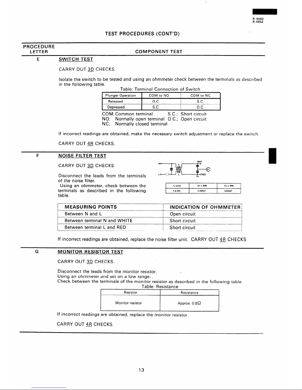
E SWITCH TEST
CARRY OUT 3D CHECKS.
Isolate the switch to be tested and using an ohmmeter check between the terminals as described
in the following table.
Table: Terminal Connection of Switch
Plunger Operation
Released
Depressed
COM to NO
COM to NC
O.C. S.C.
_--- ---
S.C. O.C.
COM; Common terminal
S.C.; Short circuit
NO; Normally open terminal O.C.; Open circuit
NC; Normally closed terminal
If incorrect readings are obtained, make the necessary switch adjustment or replace the switch.
CARRY OUT 4R CHECKS.
F NOISE FILTER TEST
CARRY OUT 3D CHECKS
Disconnect the leads from the terminal’
of the noise filter.
WHT
N*
0
g--Q
Using an ohmmeter, check between the
terminals as described in the following
table.
L hinl
Cx*ZO% CvtZmb
1.0 mti
0.066,lF 22OOpF
MEASURING POINTS
Between N and L
/ INDICATION OF OHMMETEf2i
1
I Open circuit
I
I
1 Between terminal N and WHITE
Short circuit
I
I
-..-----4
Between terminal L and RED Short circuit
---
----l
If incorrect readings are obtained, replace the noise filter unit. CARRY OUT 4R CHECKS
MONITOR RESISTOR TEST
CARRY OUT 3D CHECKS.
Disconnect the leads from the monitor resistor.
-<
Using an ohmmeter and set on a low range. .
Check between the terminals of the monitor resistor as described in the following table.
Table: Resistance
Resistor
Resistance
Monitor resistor Approx. 0.8R
If incorrect readings are obtained, replace the monitor resistor,
CARRY OUT 4R CHECKS.
13
Page 15

R -4A52
R-4E52
TEST PROCEDURES (CONT’D)
PROCEDURE
LETTER COMPONENT TEST
H
TEMPERATURE FUSE OR THERMAL CUT OUT TEST
CARRY OUT 3D CHECKS
Disconnect the leads from the terminals of the temp. fuse or thermal cut-out. Then using an
ohmmeter, make a continuity test across the each two terminals as described in the table below.
CARRY OUT 4R CHECKS
Table: Temperature Fuse Test
Parts F-ame
Temperature of Temperature of Indication of
“ON” condition . “OFF” condition ohmmeter
(closed circuit).
(open circuit). (When room
(“Cl
(“Cl
temperature is
approx. 20°C.)
Temp. fuse 1 50°C
(Magnetron)
Thermal cut-out
145°C (Oven)
This is not resetable
Above 1 50°C Closed circuit
type.
- 20°C
Above 145’C Closed circuit
If incorrect readings are obtained, replace the temp. fuse or thermal cut-out.
An open circuit temperature fuse (MG) indicates that the magnetron has overheated, this may
be due to resistricted ventilation, cooling fan failure or a fault condition within the magnetron
or HV circuit.
An open circuit thermal cut-out (OVEN) indicates that the foods in the oven catch fire, this may
be due to over heating produced by unproper setting of the cooking timer or failure of the control
panel.
MOTOR WINDING TEST
CARRY OUT 30 CHECKS
Disconnect the leads from the motor. Using an ohmmeter, check the resistance between the two
terminals as described in the table below.
Table: Resistance of Motor
1 Motors
I
Resistance
i F an motor
1 Approximately 246f2
1 Turntable motor
1 Approximately 12.5kn
If incorrect readings are obtained, replace the motor. (Also refer to test procedure J)
CARRY OUT 4R CHECKS
14
Page 16

R -4A52
R-4E52
TEST PROCEDURES (CONT’D)
PROCEDURE
LETTER
COMPONENT TEST
J
LIVE TEST FOR MOTOR WINDINGS
CAUTION: The following procedure requires the oven to be connected to the supply
1.
2.
3.
4.
5.
6.
7.
8.
9.
and should only be used if the relevant “cold” checks for the motor under test are inconclusive.
CARRY OUT 3D CHECKS
Disconnect the leads from the primary of the power transformer. Make sure that the leads
remain isolated from other oven components and chassis. (Use insulation tape if necessary.)
Connect a voltmeter, set to 250V AC, across the motor terminals. (Refer to the relevant motor
test procedure or pictorial diagram for the correct terminal numbers.)
Arrange the meter in a position where it can be read during the test.
(Do not touch the meter, meter leads or oven circuitry while the oven is active.)
Close the oven door.
Set the power level to HIGH and set the relevant timer for about three (3) minutes.
Note the reading on the meter and carefully observe the motor under test to see if it is turning.
CARRY OUT 3D CHECKS
Remove test meter leads.
1 O.Reconnect the leads to the primary of the power transformer.
If a reading of the line voltage was obtained (step 7) but the motor was not turning then it is
faulty and should be replaced. If the meter indicated that no supply was present then the wiring
I
to the motor should be checked for continuity.
K BLOWN FUSE F M8A
CARRY OUT $J CHECKS
1. If the fuse E M8A is blown, there are any shorts or grounds in electrical parts or wire harness. Check them and replace the defective parts or repair the wire harness.
2. If the fuse E M8A is blown, there is a short in the asymmetric rectifier or there is a ground
in wire harness. A short in the asymmetric rectifier may be occured due to short or ground
in H.V. rectifier, magnetron, power transformer or H.V. wire. Check them and replace the
defective parts or repair the wire harness.
3. If the fuse E M8A is blown when the door is opened, check the upper latch switch, monitor
switch, lower latch switch and monitor resistor.
If the fuse E M8A is blown by incorrect door switching replace the defective switch(s) and
the fuse E M8A.
CARRY OUT 4FJ CHECKS
-&
CAUTION\ Only replace fuse E M8A with the correct value replacement
15
Page 17

R-4A52
R-4E52
TEST PROCEDURES (CONT’D)
PROCEDURE
LETTER
COMPONENT TEST
TOUCH CONTROL PANEL ASSEMBLY TEST
M
The touch control panel consists of circuits including semiconductors such as LSI, lCs, etc.
Therefore, unlike conventional microwave ovens, proper maintenance cannot be performed with
only a voltmeter and ohmmeter.
In this service manual, the touch control panel assembly is divided into two units, Control Unit and Key Unit, and troubleshooting by unit replacement is described according to the symptoms indicated.
1. Key Unit.
The following symptoms indicate a defective key unit. Replace the key unit.
a) When touching the pads, a certain pad produces no signal at all.
b) When touching a number pad, two figures or more are displayed.
c) When touching the pads, sometimes a pad produces no signal.
2. Control Unit
The following symptoms indicate a defective control unit. Replace the control unit.
2-l In connection with pads.
a) When touching the pads, a certain group of pads do not produce a signal.
b) When touching the pads, no pads produce a signal.
2-2 In connection with indicators
a) At a certain digit, all or some segments do not light up.
b) At a certain digit, brightness is low.
c) Only one indicator does not light.
d) The corresponding segments of all digits do not light up; or they continue to light up.
e) Wrong figure appears.
f) A certain group of indicators do not light up.
g) The figure of all digits flicker.
2-3 Other possible troubles caused by defective control unit.
a) Buzzer does not sound or continues to sound.
b) Clock does not operate properly.
c) Cooking is not possible.
d) Proper temperature measurement is not obtained.
PROCEDURES TO BE TAKEN WHEN THE FOIL PATTERN ON THE PRINTED WIRING
BOARD (PWB) IS OPEN.
To protect the electronic circuits, this model is provided with a fine foil pattern added to the
primary on the PWB, this foil pattern acts as a fuse. If the foil pattern is open, follow the troubleshooting guide given below for repair.
Problem: POWER ON, indicator does not light up.
STEPS
F---l-
OCCURANCE
CAUSE OR CORRECTION
-I
1
The rated voltage is not applied to POWER terminal Check supply voltage and oven main unit.
I
’ of CPU connector (CN-A)
2 The rated voltage is applied to primary side of power Power transformer or secondary circuit defective.
transformer.
Check and repair.
3
Only pattern at “a” is broken.
*Insert jumper wire 34 and solder.
4 Pattern at “a” and “b” are broken.
*insert the coil RCILF2003YAZZ between “6 and
“d”.
/v=1L/voom wti* .
NOTE:* At the time of these repairs, make a visual in-
spection of the varistor for burning damage
and examine the transformer with tester for the
presence of layer short-circuit (check primary
coil resistance).
If any abnormal condition is detected, replace
the defective parts.
16
Page 18

R-4A52
A-4E52
TOUCH CONTROL PANEL ASSEMBLY
OUTLINE OF TOUCH CONTROL PANEL
The touch control section consists of the following
units as shown in the touch control panel circuit.
(1) Key Unit
(2) Control Unit
The principal functions of these units and the signals
communicated among them are explained below.
Key Unit
The key unit is composed of a matrix, signals generated
in the LSI are sent to the key unit through SO-S6.
When a key pad is touched, a signal is completed
through the key unit and passed back to the LSI
through K4-K7 to perform the function that was requested.
Control Unit
Control unit consists of LSI, power source circuit,
synchronizing signal circuit, ACL circuit, buzzer circuit
and indicator circuit.
1)
a
3)
LSI
This LSI controls the key strobe signal, relay driving
signal for oven function and indicator signal.
Power Source Circuit
This circuit generates voltage necessary in the
control unit.
Symbol Voltage Application
VDD -12v
LSI (ICY), ACL circuit
VREF
VP
~~i:“V LSI (ICI)
Fluorescent display tube : Grid
VF+
and anode voltage.
3V P-P F$rrenent of fluorescent display
VF- (VF+ to VF- voltage)
Synchronizing Signal Circuit
The power source synchronizing signal is available
in order to compose a basic standard time in the
clock circuit.
It accompanies a very small error because it works
on commercial frequency.
4)
5)
6)
7)
8)
ACL Circuit
A circuit to generate a signal which resets the LSI
to the initial state when power is supplied.
Buzzer Circuit
The buzzer is responsive to signals from the
to emit noticing sounds (key touch sound
completion sound).
LSI
and
Door Sensing Switch
A switch to “tell” the LSI if the door IS open or
closed.
Relay Circuit
To drive the magnetron, fan motor, turntable motor
and light the oven lamp.
Indicator Circuit
Indicator element is a Fluorescent Display.
Basically, a Fluorescent Display is a triode having
I
a cathode, a grid and an anode. Usually, the cathode of a Fluorescent Display is directly heated and
the filament serves as cathode.
The Fluorescent Display has 6-digits, 13-segments
are used for displaying figures.
I
17
Page 19

R -4A52
R-4E52
DESCRIPTION OF LSI
LSI( IZA312DR)
The I/O signals of the LSI(IZA312DR) are detailed in the following table,
PIN NO.
/ 1
__ ----
__-.--
1 SIGNAL 1 T
I
l/O
j OUT ’
Signal to sound buzzer.
A: Key touch sound (0.12 sec.).
6: Completion sound (2.4 sec.).
PIN NO. j 2
1 SIGNAL / VDD
------
- _____
Power source voitaqe: -12V
VDD voltage of power source circuit input.
I
l/O
/ IN
PIN NO. i 3
I.-SIGNAL / VREF
I
l/O
IN
A-_-
Reference voltace input terminal.
‘A reference voltage applied to the A/D converter in the LSI. The reference voltage is generally maintained at -6.15V
PIN NO.
i 4
~~-.-.-.-_I_
1 SIGNAL j VP
I
I/O
/ IN
I
Anode (segment) of Fluorescent Displav illumination voltaqe: -27V
Vp voltage of power source circuit input.
PIN NO.
1 5
1 SIGNAL / INT
I
I/O
IN
Signal svnchronized with commercial source frequency(50Hz).
This is the basic timing for time processing of LSI.
PIN NO.
/ 6
1
SIGNAL 1 CNVSS
I
I/O
1 IN
_--
_______- -
Power source voltage input terminal.
Connected to GND.
PIN NO. / 7-10
1 SIGNAL / FO-F3
I
I/O
1 OUT
Segment data signals.
Refer to the touch control panel circuit for the relationship between signals and indicators.
Normally, one pulse is output in every synchronized signal period, and input to the anode of the fluorescent display.
PIN NO. 1 11
1 SIGNAL / SO
I
I/O
1 OUT
Segment data signal.
Signal similar to FO.
Key strobe signal.
Signal applied to touch-key section.
A pulse signal is input to K4-K7 terminal while one of D-8 line keys on key matrix is touched.
Terminal not used.
PIN NO. 12
Segment data signal.
Signal similar to FO.
Key strobe signal.
1 SIGNAL j Sl
I
I/O
/ OUT
Signal applied to touch-key section.
A pulse signal is input to K4-K7 terminal while one of D-7 line keys on key matrix is touched.
18
Page 20

R-4A52
R-4E52
PIN NO. ,
j 13
1 SIGNAL 1 S2
I
I/O
j OUT
Segment data signal.
Signal similar to FO.
Kev strobe signal.
Signal applied to touch-key section;
A pulse signal is input to K4-K7 terminal while one of D-6 line keys on key matrix is touched.
PIN NO.
I 14
SIGNAL S3
I
I/O
/ OUT
Segment data signal.
Signal similar to FO.
KeV strobe signal.
Signal applied to touch-key section.
A pulse signal is input to K4-K7 terminal while one of D-5 line keys on key matrix is touched.
PIN-NO. 1 15
1 SIGNAL / S4
I
I/O
OUT
Segment data signal.
Signal similar to FO.
Kev strobe signal.
Signal applied to touch-key section.
A pulse signal is input to K4-K7 terminal while one of D-4 line keys on key matrix is touched.
-
PIN NO.
1 16
1 SIGNAL 1 S5
I I/O j OUT
Segment data signal.
Signal similar to FO.
Kev strobe signal.
Signal applied to touch-key section.
A pulse signal is input to K4-K7 terminal while one of D-3 line keys on key matrix is touched.
PIN NO. 1 17
-Seclment data siqnal.
1 SIGNAL / S6
I
I/O
1 OUT
Signal similar to FO.
Kev strobe signal.
Signal applied to touch-key section.
A pulse signal is input to K4-K7 terminal while one of D-2 line keys on key matrix is touched.
PIN NO. j 18 1 SIGNAL j 57
I
l/O
/ OUT
-____
Senment data siqnal.
Signal similar to FO.
Key strobe signal.
Signal applied to touch-key section.
A pulse signal is input to K4-K7 terminal while one of D-l line keys on key matrix is touched.
PIN NO. / 19
1 SIGNAL / XOUT
I.. I/O
1 OUT
_----
liiternal clock oscillation freduencv control output.
Output to control oscillation input of XIN.
PIN NO. 1 20
1 SIGNAL / XIN
I
I/O / IN
___---___-
Internal clock oscillation frequency input setting.
The internal clock frequency is set by inserting the ceramic filter oscillation circuit with respect to XOUT terminal.
PIN NO. / 21
1 SIGNAL j VSS
I
I/O
I IN
-
Power source voltage input terminal.
Connected to GND.
19
Page 21

R -4A52
R-4E52
PIN NO.
j 22-24 SIGNAL / Dll-D9
I
I/O
/ OUT
Diqit selection siqnal.
Refer to the touch control panel circuit about the relation between signals and digits.
Normally, one pulse is output in every synchronized signal period, and input to the grid of the fluorescent display.
PIN NO. j 25-27
.I SIGNAL i D8-D6
I I/O
1 OUT
Diqit selection siqnal.
Signal similar to Dl I.
PIN NO. / 28
Seqment data siqial.
Signal similar to FO.
1 SIGNAL / D5
I
I/O
/ OUT
PIN NO. 1 29-31
1 SIGNAL 1 D4-D2
I
I/O
/ OUT
Terminal not used.
PIN NO. 1 32
1 SIGNAL j Dl
Maqnetron Hiqh-voltaqe circuit drivinq siqnal.
To turn on and off the cook relay.
I
I/O
1 OUT
In high operation, the signals holds “H” level during microwave cooking and “L” level while not cooking. In other
cooking modes (MED. HIGH, MED., MED. LOW, LOW) the signal turns to “H” level and “L” level in repetition
according to the power level.
PIN NO. / 33
I
1 SIGNAL 1 DO
I
I/O
1 OUT
&en lamp, turntable motor and coolinq fan motor drivinq siqnal. (Square Waveform: 50Hzl
To turn on and off the control relay.
The pulse signal (50Hz) is delivered to the control relay driving circuit and cook relay control circuit.
I
c--7
v----c
----------H
L-LA--
d-.-d-
L
PIN NO. j 34
Auto clear terminal.
1 SIGNAL ) RESET
I
I/O
/ IN
I
Signal is input to reset the LSI to the initial state when power is supplied.
Temporarily set to “H” level the moment power is supplied, at this time the LSI is set.
Thereafter set at “L” level.
PIN NO. 35
I
1 SIGNAL 1 K7
I
l/O
1 IN
Sinnal coming from touch key.
When either one of D-9 line keys on key matrix is touched, a correspondin signal out of SO-S6 will be input into
K7.
When no key is touched, the signal is held at “L” level,
20
Page 22

R -4A52
R-4E52
PIN NO.
_-_- --_--
i-36
1 SIGNAL 1 K6
~-
L I/O 1 IN
_-__--_______
Signal cominq from touch key.
When either one of D-10 line keys on key matrix is touched, a corresponding signal will be input into K6.
PIN NO. i 37
1 SIGNAL j K5 1 I/O j IN
Sianal coming from touch key.
When either one of D-l 1 line keys on key matrix is touched, a corresponding signal will be input into K5.
PIN NO. / 38
1 SIGNAL j K4 IN
--___~
Signal coming from touch key.
When either one of D-l 2 line keys on key matrix is touched, a corresponding signal will be input into K4.
PIN NO. 39
1 SIGNAL j K3
I
I/O
( IN
--_
Terminal not used.
PIN NO. / 40
SIGNAL j K2
I
I/O
/ IN
Input signal which communicates the do&r open/close information to LSI.
Door closed; “H” level signal.
Door opened; “L” level signal.
PIN NO. 1 41
1 SIGNAL 1 Kl
I
I/O
1 IN
Terminal not used.
PIN NO. 1 42
1 SIGNAL / KO
Terminal not used. Connected to GND.
I/O
I
I IN
-I_---_---
21
Page 23

R-4A52
R-4E52
SERVICING
I. Precautions for Handing Electronic
Components
This unit uses PMOS LSI in the integral part of the
circuits. When handing these parts, the following
precautions should be strictly followed.
PMOS LSI have extremely high impedance at its
input and output terminals. For this reason, it is
easily influenced by the surrounding high voltage
power source, static electricity charged in clothes,
etc,and sometimes it is not fully protected by the
built-in protection circuit.
In order to protect PMOS LSI.
1)
2)
When storing and transporting, thoroughly
wrap them in aluminum foil.
Also wrap PW
aluminium foil.
When soldering, ground the technician as
shown
in the figure and
soldering iron and work table.
use grounded
boards contaf-ning them in
2. Shapes of Electronic Components
Transistor
DTA 143ES
Transistor
2SB910M
L
DTC 114ES
DTD 143ES
3. Servicing of Touch Control Panel
We describe the procedures to permit servicing the
touch control panel of the microwave oven and the
cautions you must consider when doing so.
To carry the servicing, power supply to the touch
control panel is available either from the power line
of the oven proper itself of from an external power
source.
(1) Servicing the touch control panel with
power supply from the oven proper:
CAUTION:
THE HIGH VOLTAGE TRANSFORMER OF
THE MICROWAVE OVEN IS STILL ALIVE
TO GIVE YOU DANGER DURING SERVICING.
Therefore, when checking the performance of
the touch control panel,put the outer cabinet
on the oven proper to keep from touching the
high voltage transformer, or unplug the primary
terminal (connector) of the high voltage transformer to turn it off; and the end of such connector shall be insulated with an insulating
tape.
After servicing, be sure
leads
to their original locations.
to replace the
A. On some models, the power supply cord be-
tween the touch control panel and the oven
proper is so short that they can’t be separated
‘from each other.
4. Servicing Tools
Tools required when servicing the touch control
panel assembly.
1) Soldering iron: 30W (To prevent leaking cur-
rent, it is recommended to use a soldering iron with
a grounding terminal.)
2) Oscilloscope:
Single beam, frequency range:
DC - IOMHz type or more ad-
vanced model.
3) Others: Hand tools
5. Other Precautions
For those models, therefore, check and repair
all the controls (with the sensor-related ones
included) of the touch control panel while
keeping it in contact with the oven proper,
B. On some models, on the other hand, the power
supply cord between the touch control panel
and the oven proper is so long that they may
be separated from each other. For those models, therefore, it is allowed to check and repair
the controls of the touch control panel while
keeping it apart from the oven proper;in this
case you must short both ends of the stop
switch (on PWB) of the touch control panel
. with a jumper, which brings about an opera-
tional state that is equivalent to that with the
oven door being closed.
As to the sensor-related controls of the touch
control panel, their checking is allowed if the
dummy resistor(s) whose resistance is equal to
that of those controls is used.
(2) Servicing the touch control panel with
power supply from an external power
source:
Disconnect the touch control panel completely
from the oven proper,and short both ends of
the stop switch (on PWB) of the touch control
panel,which brings about an operational state
that is equivalent with the oven door being
closed. And connect an external power source
to the power input terminal of the touch control
panel, and then it is allowed to check and repair
the controls of the touch control panel;as in the
case of (1) - B above, it is here also possible to
check the sensor-related controls of the touch
control panel by using the dummy resistor(s).
1) Before turning on the power source of the
control unit, remove the aluminum foil applied
for preventing static electricity.
2) Connect the connectors of the indicator and
key units to the control unit taking care that the
lead wires are not twisted.
3) After aluminum foil is removed, take extra care
that abnormal voltage due to static electricity
etc. is not applied to the input or output terminals.
4) Attach connectors, electrolytic capacitors, etc.
to PWB, taking care that all connections are
tight.
5) Be sure to use specified components where
high precision is required.
22
Page 24

R -4A52
R-4E52
COMPONENT REPLACEMENT AND ADJUSTMENT PROCEDURE
WARNING: Avoid possible exposure to microwave energy. Please follow the instructions below
before oDerating the oven.
1. CARRY OUT 3D CHECKS.
2. Make sure that a definite “click” can be heard when
the microwave oven door is unlatched. (Hold the
door in a closed position with one hand, then push
the door open button with the other, this causes the
latch heads to rise, it is then possible to hear a
“click” as the door switches operate.)
3. Visually check the door and cavity face plate for
damage (dents, cracks, signs of arcing etc.).
I. Door does not close firmly.
2. Door hinge, support or latch hook is damaged.
3. The door gasket or seal is damaged.
4. The door is bent or warped.
5. There are defective parts in the door interlock system.
6. There are defective parts in the microwave generat-
ing and transmission assembly.
7. There is visible damage to the oven.
Carry out any remedial work that is necessary before
operating the oven.
Do not operate the oven:
I. Without the RF gasket (Magnetron).
2. If the wave guide or oven cavity are not intact.
Do not operate the oven if any of the following con-
3. If the door is not closed.
ditions exist;
4. If the outer case (cabinet) is not fitted.
Please refer to ‘OVEN PARTS, CABINET PARTS, DOOR PARTS’, when carrying out any of the following removal
procedures:
OUTER CASE REMOVAL
3. Remove the screws from rear and .along the side
To remove the outer case, proceed as follows.
edge of case.
1. Disconnect oven from power supply.
4. Slide the entire case back about 1 inch (3cm) to
2. Open the oven door and wedge it open.
free it from retaining clips on the cavity face plate.
5. Lift the entire case from the oven.
moved.
6. Discharge the HV capacitor before carring out any
N.B.; Step I,2 and 6 form the basis of the 3D checks.
further work.
CAUTION: DISCHARGE
7. Do not operate the oven with the outer case re-
HIGH VOLTAGE
CAPACITOR BEFORE TOUCHING ANY
OVEN COMPONENTS OR WIRING.
HIGH VOLTAGE COMPONENTS REMOVAL
(HIGH VOLTAGE CAPACITOR AND HIGH VOLTAGE RECTIFIER ASSEMBLY)
To remove the components, proceed as follows.
1. CARRY OUT 3iJ CHECKS
2. Disconnect the high voltage wire A from the
7. Disconnect high voltage wire A and terminals of
high voltage rectifier assembly from high voltage
capacitor.
magnetron.
3. Disconnect the filament lead(shorter one) of the
8. Now high voltage rectifier assembly and capacitor
power transformer.
should be free.
I
4. Disconnect the high voltage wire of the H.V.
rectifier assembly fromt he high’voltage capacitor.
5. Remove one (1) screw holding capacitor holder to
the oven cavity.
6. Remove one (1) screw holding earth side terminal
of high voltage rectifier assembly, and remove
capacitor holder from the high voltage capacitor,
CAUTION: W-HEN REPLACING HIGH VOLTAGE
RECTIFIER ASSEMBLY, ENSURE THAT
THE CATHODE (EARTH) CONNECTION
IS SECURELY FIXED TO THE
CAPACITOR HOLDER WITH A EARTHING SCREW.
POWER TRANSFORMER REMOVAL
1. CARRY OUT3JCHECKS
4. Disconnect the high voltage wire of H.V. rectifier
2. Remove the fan motor assembly from the oven re- assembly from the power assembly.
ferring to “FAN MOTOR ASSEMBLY”.
5. Remove the two (2) screws holding the transformer
3. Disconnect the the filament lead of the power
to bottom plate right.
transformer from high voltage capacitor.
6. Remove the transformer from the bottom plate right.
7. Now, the power transformer is free.
23
Page 25

R-4A52
R-4E52
MAGNETRON REMOVAL
1. CARRY OUT 3D CHECKS
2. Disconnect the H.V. wire A and filament lead(longer
one) of the transformer from the magnetron.
3. Release the main harness from the tabs of the air
duct.
4. Remove the air duct from the oven cavity.
5. Carefully remove four (4) screws holding
magnetron to waveguide, when removing the
screws holding the magnetron to prevent it from
falling.
6. Remove the magnetron from the waveguide with
care so the magnetron antenna should not hit by
any metal object around the antenna
7. Remove the magnetron cushion from the magnetro.
CAUTION: WHEN REPLACING THE MAGNETRON,
BE SURE THE R.F. GASKET IS IN
PLACE AND
THE
MAGNETRON
MOUNTING SCREWS ARE TIGHTENED
SECURELY.
CONTROL PANEL REMOVAL
1. CARRY OUT 3D CHECKS
-_
2. Disconnect the main harness and low voltage harness from the control panel.
3. Remove the single (1) screw holding the control
panel to the oven cavity.
4. Lift up the control panel assembly and pull it forward. Now, the control panel assembly is free,
TURNTABLE MOTOR REMOVAL
I. Disconnect the oven from power supply.
2. Remove the turntable motor cover by removing the
two (2) screws.
3. Disconnect the wire lead from turntable motor and
remove the two(2) screws holding the turntable
motor.
4. Remove the O-ring and washer from the turntable
motor.
5. Turntable motor is now free.
XFTSD40PlOOOO
Figure C-l.
NOTE: The two (2) screws holding the turntable motor
to the oven cavity must be used the specified
screws(XFPSD40P08000) as listed on Parts
list.
TURNTABLE COUPLING. REMOVAL
1. Remove the turntable motor, refer to “Turntable
Motor Removal”.
2. At the time turntable coupling will be free.
TURN TABLE
COUPLING
BOTTOM
OVEN CAVITY
T.T. MOTOR
ANGLE
Figure C-2. Turntable Coupling
FAN MOTOR ASSEMBLY REMOVAL
1. CARRY OUT 3D CHECKS.
2. Disconnect the wire leads from the fan motor.
3. Disconnect the H.V. wire A and the filament
lead(longer one) of the power transformer from the
magnetron.
5. Release the tabs of the fan duct from the holes in
the bottom plate right and the back plate of the
oven cavity.
6. Release the main wire harness from the hole in the
4. Release the H.V. wire A and filament lead from the
fan duct.
holes in the fan duct.
7. Now, the fan motor assembly is free.
24
Page 26

R-4A52
R-4E52
OVEN LAMP SOCKET REMOVAL
1.
2.
3.
4.
5.
1.
2.
3.
4.
5.
6.
7.
CARRY OUT 3D CHECKS
Lift up the tab holding the oven lamp socket.
Remove the oven lamp socket.
Pull the wire leads from the oven lamp socket by
pushing the terminal hole of the oven lamp socket
with the flat type small screw driver.
Now, the oven lamp socket is free.
Oven lamp socket
Flat type
screw dri
Figure C-3. Oven lamp socket
UPPER LATCH SWITCH, LOWER LATCH SWITCH,
STOP SWITCH AND MONITOR SWITCH REMOVAL
CARRY OUT 3D CHECKS.
Remove the air duct from the oven cavity.
Disconnect the main wire harness and switch harness from the control panel.
Disconnect the leads from all switches.
Remove the two (2) screws holding the latch hook
to the oven cavity.
Remove the latch hook.
Push the retaining tab slightly and remove the
switch.
Monitor
I /
Upper latch switch
switch
Lower latch switch
Figure C-4. Switches
25
Page 27

R -4A52
R-4E52
UPPER LATCH SWITCH, LOWER LATCH SWITCH,
STOP SWITCH AND MONITOR SWITCH ADJUSTMENT
If the lower latch latch switch, stop switch, upper latch
5. Reinstall outer case and check for microwave
switch and monitor switch do not operate properly due
leakage around the door with an approved micro-
to a mis-adjustment, the following adjustment should
wave survey meter.
(Refer to Microwave Measure
be made.
ment Procedure.)
1. CARRYOUT3DCHECKS
2. Loosen the two (2) screws holding the latch hook
to the oven cavity front flange.
3. With door closed, adjust the latch hook by moving
it back and forward, or up and down. In and out
play of the door allowed by the latch hook should
be less than 0.5 mm. The horizontal position of the
latch hook should be placed where the stop switch
and monitor switch have activated--with the door
closed.
LATCH
The vertical position of the latch hook should be
placed where the lower latch switch and upper
latch switch have activated with the door closed.
4. Secure the screws with washers firmly.
5. Make sure of the upper latch switch, stop switch,
lower latch switch and monitor switch operation. If
those switches have not activated with the door
closed, two (2) screws holding latch hook to oven
cavity front flange and adjust the latch hook position.
After adjustment, make sure of following:
1. In and out play of door remains less than 0.5 mm
when latched position. First check latch hook position, pushing and pulling the door toward the oven
i
face. The results (plays of the door) should be less
I
than 0.5mm.
2. The upper latch switch and lower latch switch interrupt the circuit before the door can be opened.
3. The monitor switch contacts close when the door
is opened.
4. The stop switch contacts open when the door is
opened.
Figure C-5 Latch Switches Adjustment
26
Page 28

R -4A52
R-4E52
DOOR REPLACEMENT AND ADJUSTMENT
DOOR REPLACEMENT
1. CARRY OUT 3D CHECKS
2. Remove two (2) screws holding the lower oven
hinge to the oven cavity. The lower oven hinge is
now free.
3. ,“z;re the door assembly from the upper oven
4. Remove door assembly.
5. Door assembly is now free.
6. Re-install upper oven hinge to the new door assembly.
7. On re-installing new door assembly, secure the
lower oven hinges with the two (2) mounting
screws to the oven cavity. Make sure the door is
parallel with bottom line of the oven face plate and
the latch heads pass through the latch holes cor-
rectly.
8. CARRY OUT JIFJ CHECKS
Note: After any service to the door, an approved
microwave survey meter should be used to
assure compliance with proper .microwave ra-
diation standards. ( Refer to Microwave
Measurement Procedure.)
DOOR ADJUSTMENT
When removing and/or loosening hinges such as in
door replacement, the following adjustment criteria are
taken.
Door is adjusted to meet the following three
conditions by keeping screws of hinge loose.
1. Adjust door latch heads at a position where they
smoothly catch the latch hook through the latch
1
holes. Refer to latch switch adjustments.
2. Deviation of the door alignment from horizontal line
of cavity face plate is to be less than 1 .Omm.
3. The door is positioned with its face depressed toward the cavity face plate.
4. Reinstall outer case and check for microwave
leakage around the door with an approved microwave survey meter.
(Refer to Microwave Measure
ment Procedure.)
CABINET
Figure C-6. Door Assembly Replacement
and Adjustment
CHOKE COVER REMOVAL
1. Insert an iron plate(thrckness of about 0.5mm) or
flat type screw driver to the gap between the choke
cover and door panel as shown in the figure to free
the engaging part.
2. Lift up the choke cover, now cover is free.
FLAT TYPE
SCREW-DRIVER
PROTECT BY TAPE
FLAT TYPE
SCREW-DRIVE
Figure C-7. Choke Cover Removal
DOOR PARTS REMOVAL
Remove the door assembly, referring to from item 1
through item 5 of “DOOR REPLACEMENT”.
1. Place the door assembly on a soft c,loth with latch
heads facing up.
2. Remove the.* choke cover, referring to “CHOKE
COVER REMOVAL”.
LATCH HEAD REMOVAL
3. Lift up the latch head towards the direction that the
arrow shows in the figure C-8, and release the latch
head from the holes in the door panel.
4. Release the latch spring with the latch head from
the tabs of the door panel.
5. Release the latch spring from the latch head.
6. Now, the latch head is free.
27
Page 29

R-4A52
R-4E52
\
Tab of the door panel
Figure C-8. Latch head removal
Figure C-9. Latch head re-install
LATCH HEAD RE-INSTALL
1. Pick up the latch spring and catch the one ring of
the latch spring on the tab of the door panel as
shown in Figure C-9.
2. Catch the other ring of the latch spring on the tab
of the latch head.
3. Install the latch head to the holes in the door panel.
POWER SUPPLY CORD REPLACEMENT
(FOR AUSTRALIA MODEL)
Removal
1. CARRY OUT 30 CHECKS.
2. Disconnect the brown wire of the power supply
cord from the fuse holder.
3. Remove the connector CE-230 by cutting the connected wire leads to it.
4. Remove the single (1) screw holding the
green/yellow wire of the power supply cord to the
oven cavity.
5. Remove the single (1) screw holding the cord
anchorage to the oven cavity.
6. Remove the power supply cord from the oven.
Re-install
1. Insert the power supply cord into the cord
anchorages.
2. Connect the brown wire of the power supply cord
to the fuse holder.
3. Install the green/yellow wire of the power supply
cord to the oven cavity with the single (1) screw
tightly.
4. Make sure that the blue wire and the white wires
are stripped for 15 mm length as shown in Figure
C-II.
5. Wind the conductors of Blue and White wires each
other.
6. Insert the stripped wire leads into the connector
CE-230.
7. Clamp the connector CE-230 with the correct tool
tightly.
Cord anchorage
I
Brown wire \
Fuse holder
Green/Yellow wire
Figure C-10 Power Supply Cord Replacement
for Australia Model
Blue wire of power supply cord
White wire of main harness
33::
Conductors
Connector CE-230
Figure C-II Wiring
28
Page 30

FL4A52
R-4E52
POWER SUPPLY CORD REPLACEMENT
(FOR NEW ZEALAND MODEL)
Removal
1.
2.
3.
4.
5.
CARRY OUT 3D CHECKS
Loosen the two (2) screws holding the brown and
blue wires of the power supply cord to the cord
connector on the noise filter.
Loosen the single (1) screw holding the earth angle
and earth wire of power supply cord.
Remove the single (1) screw holding the cord
anchorages to the oven cavity.
Remove the power supply cord.
Re-install
1.
2.
3.
4.
5.
Insert the power supply cord into the cord
anchorages.
Insert the brown and blue wires of power supply
cord into the terminals of cord connector, referring
to pictorial disgram. And tighten the screws.
Insert the earth wire of power supply cord into the
earth angle, and tighten the screw holding the earth
angle.
Tighten the single (1) screw holding the cord
anchorages.
CARRY OUT Q CHECKS
Note:Step 5 above is important, and it must be done
after replacing power supply cord.
Procedure
1. Pushing the lever of positive lock@ connecotr,
2. Pull down the connector from the terminal.
3. Now, the connector is free.
Note: If the positive lock@’ has a insulation sleeve, first
remove it. If you do not so, you can not push
the lever of positive lock@’ .
CAUTION: The positive lock@ terminal can not be
disconnected by only pulling. Because
once you (Service personnal) have connected the positive lock@ connector to the
terminal, the positive lock connector has
been locked.
Cord connector
Blue wire
rem I Yellow wire
Figure C-12. Power Supply Cord Replacement
For New Zealand Model
Positive lock@
cunnector
\
Terminal
Figure C-13. How to release the
positive lock
connector
29
Page 31

R -4A52
R-4E52
MICROWAVE MEASUREMENT
After adjustment of door latch switches, monitor
switch and door are completed individually or collectively, the following leakage test must be performed
with a survey instrument and it must be confirmed that
the result meets the requirements of the performance
standard for microwave oven.
REQUIREMENT
The safety switch must prevent microwave radiation
emission in excess of 5mW/cm2 at any point 5cm or
more from external surface of the oven.
PREPARATION FOR TESTING:
--
Before beginning the actual test for leakage, proceed
as follows;
1. Make sure that the test instrument is operating
normally as specified in its instruction booklet.
Important:
Survey instruments that comply with the requirement for instrumentations as prescribed by the per-
formance standard for microwave ovens must be
used for testing.
Recommended instruments are:
NARDA 8100
NARDA 8200
HOLADAY HI 1500
SIMPSON 380M
2. Place the oven tray into the oven cavity.
3. Place the load of 275 +I 5ml of water initially at
20f5”C in the centre of the oven tray. The water
container should be a low form of 600 ml beaker
with inside diameter of approx. 8.5cm and made of
an electrically non-conductive material such as
glass or plastic.
The placing of this standard load in the oven is im-
portant not only to protect the oven, but also to‘in-
sure that any leakage is measured accurately.
4. Close the door and turn the oven ON with the timer
set for several minutes. If the water begins to boil
before the survey is completed, replace it with
275ml of cool water.
5. Move the probe slowly (not faster that 2.5cm/sec.)
along the gap.
6. The microwave radiation emission should be meas-
ured at any point of 5cm or more from the external
surface of the oven.
Microwave leakage measurement at 5 cm distance
30
Page 32

R-4A52
R-4E52
TEST DATA AT A GLANCE
IP
arts
1 Symbol 1 Value / Data
I---
F
Fuse
-
Monitor resistor
RI
Temp. fuse (MG)
TF
Thermal cut-out (OVEN)
TC
Oven lamp
OL
High voltage capacitor
Magnetron
Power transformer
C
MG
T
M8A 250V
0.8zT 20W
150°C
145°C
25W El4 250V
1 .I 3pF AC 21 OOV
Filament < 1 n
Filament -
chassis 00 ohm.
Filament winding < 1 R
Secondary winding Approx. 78.9n
Primary winding Approx. 1.42231
TEST POINTS ON CONTROL UNIT
In/Out put terminal
Input (SUPPlY)
input (Stop switch)
Output (Oven lamp
Fan motor, Turntable motor)
Output (Power transformer)
Output (Earth)
Resistance
Test point
Volt (Disconnect the power plug
and door is closed)
Al - A3 240V Approx. 9000
Bl- B2
OR
Al - A5
240V
98Q
Al - A7
240V 1 .7n
B2 - Chassis
Oil
WARNING: DISCONNECT THE PLUG WHEN MEASURING RESISTANCE.
31
Page 33

14
240V-+OHr A
240V-50Hz
AC CORD CONNECTION
BRN : BROWN
BLU : BLUE
G-Y : GREEN AND
YELLOW STRIPE
/lB : SECTIONAL AREA
OF 0.75mm2 MIN
I
l.DOOR CLOSED
j 2.~&O;;s;~~;ARS 1
.--
swi:
LfPPER
LATCH
SWITCi-
-
> i
I
l 1
AC CORD CONNECTION
BRN :
BROWN
BLU : BLUE
G-Y : GREEN AND
YELLOW STRIPE
/lB : SECTIONAL AREA
OF 0.75mm2 MIN.
5w2:
SE:
SWITCH
T: POWER
TRANSFOAMER
n
H.V. RECTIFIER
MG: MA-
Figure O-1 (a).
Oven Schematic-OFF Condition For Australia Model
I
SCHEMATIC
YOTE: CONDITION
OF OVEN
l.DODR CLOSED
2.COOKING TIME
PROGRAMMED
3.START KEY
TOUCHED
sw1:
UPPER
LATCH
SWITCH
F:
FUSE
M0A
SW2
LOWER
LATCH
SWITCH
Figure O-2 (a).
v
Oven Schematic-ON Condition For Australia Model
Page 34

240-6CiHz
BLU/lB m/10
pg-,
__~----_-_--_ L
LINE cR0ss
CAPACITOR
-( -7
(I
O.O68/‘(AC25OV
I I
0
F: FUSE
1
NOISE SVPPRESSION COIL
MBA
4
J;L
. !
1 1 NOISE SUPPRES;;“” COIL FE ] /
1
A !
LINE BYPASS
NOISE
FILTER
AC CORD CONNECTION
BRN :
BROWN
BLU : BLUE
G-Y : GREEN AND
AC CORD CONNECTION
BRN : BROWN
BLU : -BLUE
G-Y :
GREEN AND
YELLOW STRIPE
/lB : SECTIONAL AREA
OF 0.75mm2 MIN.
----------------+--I
YELLOW STRIPE
/lB : SECTIONAL AREA
OF 0.75mm2 MIN.
3
TC:
THERMAL
CUT-OUT
143 (OVEN)
r-----
-----
1
7-!&--1 :j_ ql iikMGj
I.._.
UPPER
LATCH
SWITH
SWl:
UPPER
LATCH
SWITH
SW2
LOWER
LATCH
SWITCH
SW3 MONITOR
R: MONITOR
SWITCH
RESISTOR
0. w2ow
SCHEMATIC
NOTE: CONDITION
OF OVEN
l.OOOR CLOSED
SW3 MONITOR
R: MONITOR
SWITCH
RESISTOA
0. w2ow
l.DOOR CLOSED
2.CLOCK APPEARS
ON DISPLAY
2.COOKING TIMED
PROGRAMMED
3.START KEY
TOUCHED
I
I I
H.V. RECTIFIER
H.V. RECTIFIER
Figure O-2 (
b).
L------l
ffi: MAGbETRON
,
Figure O-l (b).
Oven Schematic-OFF Condition For New Zealand Model
Oven Schematic-ON Condition For New Zealand Model
Page 35

R -4A52
R-4E52
1 2 3 I 4 I
I 5 6
-
2
8
n
:A
I
i-
i’
lC
lo
I
I-l
I
iE
IF
1
1.
I
G
I
I
lH
j
i
A
B
C
~
D
E
F
G
H
>
7
mfxz
I
2
G
&
2
co
N
9
PC:
2
4
r”
5
az
z
z
a
5
U
5
B
.n
1
5
5
ii
.
5
r
CA
i
5
.U
..a
81
3fh
93 I-
I-
crm3
1
I
i
1
1
i!
P
@
-H-Y
4
pgg
[TIP
$97
l-01-c
. .
P
Q
%
L-
I
I I
I I
t
11
;j
6
l-
E
4
I 9
. .
iit v 0
w
5X
8
k
81 -II
kg
$3
EC
gg
. .
2
. .
z
. .
W
I-
‘0
Z
1 2
I
---~
, 3 4 5 6
34
Page 36

R -4A52
R-4E52
1 2 3 4 ! I 5 6 .
-____-
-
t
N
z
0;:
liij
:
2
z
2
:
N
s
z”
z
IA
E
ii
ii!
*n
z
E
G
iT
.
s
7
c;,
z!!
.is
LL
1
9
(I
9
42
A-Y
>
a3g
ii?%
WI--Lo
F&z
. .
v
43
i
I I
I
a!
L::
zcn
ti
@
8#
E
z
8
I I
--
gg
6
t-
E
3
?Y
x
2
8F
s2
-luJ
. .
:
E
6
-I--
u
om
UW
8
, iTI
. .
ifi
1
I
L-u >-P
ru U-d u
Etu4Jal
e--J
c-f+ c
o,culc
fEE
I
. .
F
z”
I
I
1 2
3 4 5 6
35
Page 37

R -4A52
R-4E52
1 I 2
,
/ 3 4
I 5
I
6
u
z
z
PBY
2
em
PI
Y
x
gg=
El:::
XS’B
sz
07
$
,z;
S.-r
ZZZO
::
d
5’
6L-‘c
4
1 2 3 4 I 5 6
(
iz
3 1 c
k
+
.-
z
t
6 I
.z
ii
t
p ’
L
E
00 lE
(Ij
cd j
2
ii 1 ’
.-
LL
F
1
36
Page 38

R-4A52
R-4E52
r
A
,
BI
C
D
E
F
G
H
L
r
E
I”
$4
,:z
B
CD”
iz6
fZd.8
z
8Z
x
8mn=
“X
::
“p::
45
‘PZ:!
EZBB
N
e
sif2
>
R
:: * 2
a z z
5 % z
>!2,
PBP
z c
z
;: ; 3
;p”
P
:: -) ::
c e c
z z s
., .
cs
1
T
Gi
ii
Y
E
.C
5
6
z
5
e
z
E
8
i
cd
c
s
.-
U
P
1
2
3 4
5
6
37
Page 39

R -4A52
R-4E52
.\
-w**
-1 “_
-* “”
I
5 _ IO: BFzoo--~“-
:““*‘I -
“-.>i--. x
L -*
I 1 ”
.r -
\ ^I
* R64 is
on this
inserted
position.
__--
1
---
9
L
w
IJl
-a
n
RY- I
CN-A
Figure S-4. Printed Wiring Board
-
A
0
C
D
E
F
G
H
38
Page 40

R-4A52
R-4E52
PARTS LIST
Note :
The voltage supplied to the parts “*rr are greater than 250V.
REF. NO. 1 PART NO.
I
DESCRIPTION
1 my ICODE
*
*
ELECTRICAL PARTS
l- 1
QFS-TA014WREO TF: Temp. fuse 150°C (MG) 1 AG
l- 2
QFSHDA002WREO Fuse holder (For Australian Model)
1
AF
l- 3
QSW-MA009WREO SW3:
Monitor switch (V-5220D-070)
1
AF
l- 4
QSW-MA007WREO SWl: Upper latch switch (V-5230D-069) 1 AF
l- 5
RTHM-A057WREO TC: Thermal cut-out 145°C (OVEN) 1
AG
l- 6
QACCAAOllWREO Power supply cord (For Australian Model)
1
QACCAA018WREO Power supply cord (For New Zealand Model)
AQ
l- 6
AQ
l- 7
FW-QZA070WRKO H.V. rectifier assembly :: AY
l- 8
RC-QZA075WREO C: High Voltage capacitor
1 AU
l- 9
QSOCLAOllWREO Oven lamp socket
1
AH
l-10
RLMPTA029WREO OL: Oven lamp
1 AL
l-11
QFS-CAOlOWREO F: Fuse M8A
1
AE
l-12
FMOTEA212WRKO FM: Fan motor assembly fl~fl~~2/0~fi~0
1
l-13
RTRN-A288WREO T: Power transformer
1
BM
l-14
RV-MZA089WREO MG: Magnetron (For Australian Model)
1 BG
l-14
RV-MZA108WREO MG: Magnetron (For New Zealand Model)
1 BG
l-15
RMOTDA133WREO TTM: Turntable motor
1 AW
l-16
RR-WZA003WREO R: Monitor resistor 0.8 n 2OW
1
AG
l-17
QSW-MA007WREO SW2:
Lower latch switch 1 AF
l-18
QSW-MA007WREO SW4: Stop switch
1 AF
l-19
FPWBFA221WRKO Noise filter (For New Zealand Model)
1 AX
CABIN ET PARTS
2- 1 FHNG-A128WRMO Lower oven hinge
1
AF
2- 2 GCABUA310WRPO Outer case cabinet
1 BF
2- 3 MHNG-A227WRMO Upper oven hinge
1
AE
2- 4
PCOVPA211WRPO Turntable motor cover
1 AE
2- 5 PCAPHA015WREO Cabinet cap white
2 AD
2- 6
GLEGPA023WREO Foot
4 AC
CONTROL PANEL PARTS
;I :A
CPWBFA366WRKO Control unit (New Zealand only)
QCNCMAO78DREO 4-pin connector (A)
3- 1B QCNCM0027WREO 2-pin connector (B)
3- 1c QCNCWAO3ODREO 12-pin connector (D)
3- 1D RV-KXA037DREO Fluorescent display tube
Cl
RC-KZA032DREO Capacitor
O.lpF 50V
c2
VCEAB31VW108M Capacitor
1000pF 35V
c5 VCEAB31EW476M Capacitor
47pF 25V
C6,7,20,VCKYBllEX103N Capacitor
O.OlpF 25V
C21,40
-.
c50-53
C80
VCKYDllHB331K Capacitor
VCEAB31HW104M Capacitor
330pF 50V
C81
O.lpF 50V
C82
VCEAB31HW225M Capacitor
2.2pF 50V
c90
VCEAB31HW335M Capacitor
3.3pF 50V
VCC-F31H-680J Capacitor
68pF 5ov
c91
CF90
VCC-F31H-181J Capacitor
180pF 5ov
Dl-5
RCRS-2008DREO Ceramic filter KBRGPOB (6OOkHz)
VHDllESl///-1Diode (11ESl)
D51-57,
VHDlSS27OA/-1Diode (lSS270A)
D80-83
ICl
RH-IZA312DREO LSI
Ql
Q20,82
VS2SB910MR/-4 Transistor (2SB910MR)
VSDTC114ES/-3 Transistor (DTC114ES)
8;:
VSDTA114ES/-3 Transistor (DTA114ES)
VSDTD143ES/-3 Transistor (DTD143ES)
R2
VRD-B12HF272JResistor
R3
VRD-B12HF102J Resistor
2.7Kn 1/2W
R4
VRD-B12HF112J Resistor
lKf2 1/2W
l.lKn 1/2W
1
BP
1 AD
AB
i AE
1
AU
1
AB
1 AG
AB
5' AA
4 AA
1
AC
1 AA
1 AA
1 AA
AB
i AF
5 AB
11 AA
AS
:: AC
2
AB
1 AB
1 AC
AB
:: AA
1
AA
39
Page 41

I?-4A52
R-4E52
““LFi
I IITj vv,,ayc J”ppllc” L” LIIC pcx,,a CIIC- ylcxaLrl 111(111 L.J”Y.
REF. NO. PART NO. DESCRIPTION
R5 VRD-B12EF821J Resistor
82OSl 1/4W
R10 VRD-B12EF123J Resistor 12kn 1,'4W
R11,20, VRD-B12EF103J Resistor lOkf2 1/4W
R64
R30,60
VRD-B12EFlOZJ Resistor
lkn 1/4W
R31
VRD-B12EF332J Resistor 3.3k0 1/4W
R40
VRD-B12EF473JResistor 47kn 1/4W
R41
VRD-B12EF563J Resistor 56kfi 1/4W
R50-53 VRD-Bi2EF183J Resistor
18kn 1/4W
R151-157
Q’TY
CODI
1 AA
1
AA
3
AA
2 AA
1 AA
AA
i AA
11 AA
R80 VRD-B12EF623J Resistor 62Kn 1/4W
R81 VRD-B12EF471J Resistor 47on 1/4w
R82 VRD-B12EF201J Resistor 2000 1/4w
R83 VRD-B12EF390J Resistor 390 1/4w
R90
VRD-B12EF122J Resistor 1.2Kn 1/4W
RYl RRLY-A02ODREO Relay (OJ-SH-112LM)
RY2 RRLY-A059DREO Relay (VS14MB-NR)
SP30 RALM-AOlODREO Buzzer (PKM22EPT-CA)
Tl RTRNPA064DREO Transformer
VRSl RH-VZAOlODREO Varistor (TNR15G471K)
ZDl VHEHZ12Bl//-1 Zener diode (HZ12B-1)
ZD2 VHEHZGC2///-1 Zener diode (HZ6C-2)
ZD3 VHEHZGA3///-1 Zener diode (HZ6A-3)
ZD10,20 VHEHZllA3//-1Zener diode (HZllA-3)
3- 2 - HPNLCA903WRFO Control panel frame (R4A52)
HPNLCA891WRFO Control panel frame (R4E52)
3- 3
- DUNTKA430WRKO Key unit assembly (R4A52)cDUNTKA423WRKO Key unit assembly (R4E52)
3- 4 GMADIA055WRFO Display window
3- 5 JBTN-A596WRFO Open button (R4A52)
JBTN-A659WRFO Open button (R4E52)
3- 6 MSPRTA050WREO Open button spring
3- 7
XEPSD30PlOXSO Screw; Control unit mtg.
1AA
1
AA
1 AA
1
AA
1AA
AH
i AK
1 AA
AS
i AE
1 AB
1AA
AC
; AA
1 AS
1
AS
1 BC
BC
t AE
1 AF
1
AF
1 AA
3 AA
OVEN P’ARTS
4- 1 LBNDKA038WRPO Capacitor holder
1 AH
4- 2
LSTPPA069WRFO Cord anchorage (upper) 1
AE
4- 3
LSTPPA070WRFO Cord anchorage (lower)
1
AD
;I ";
FDAI-A138WRYO Bottom plate right
1
PDUC-A406WRFO Air duct
1 AK
;I g
PHOK-A065WRFO Latch hook
AL
PCUSUA236WRPO Partition cushion
i AF
4- .7 PCUSUA237WRPO Waterproof cushion
1 AF
tr1:
FOVN-A21OWRTO Oven cavity
1 AK
GDAI-AlGlWRWO Bottom plate left
1 AH
4-11
MLEVPA166WRFO Latch lever
1
4-12 FROLPA047WRKO Roller stay
1.g
4-13 NTNT-A036WREO Turntable
1 AX.'
4-14 GFTA-A008WRWO Oven lamp access cover
1 AF
4-15 NCPL-AOlSWRFO Turntable coupling
1 AD
4-17 PCOVPA212WREO Waveguide cover
AF
4-18
PCUSUA157WRPO Cushion
:: AC
4-19
PCUSUA235WRPO Exhaust cushion
1 AF
4-20 PPACGA096WREO O-ring
1
4-21
PFILWA041WREO Oven lamp filter
1 AA
4-22
LBOS-A045WREO Waveguide stub
1
4-23
PGIDHA044WRPO Magnetron air guide
1
4-24
LANGQA167WRMO Earth angle' (For New Zealand Model)
AB
4-25
LANGQA288WRPO Noise filter angle (For New Zealand Model)
; AC
4-26
PCUSU0158YBPO Cushion
1
AA
4-27
PCUSGA305WRPO Oven cushion (R-4A52)
AD
4-28
PCUSUA278WRPO MG cushion
40
Page 42

R -4A52
R-4E52
Note :
The voltage supplied to the parts ‘I*” are greater than 250V.
,
REF. NO. 1 PART NO.
I
DESCRIPTION
10’~~ ICODE
DOOR PARTS
CDORFA464WRKO Door assembly, complete. (R-4E52)
CDORFA467WRKO
Door assembly, complete. (R-4A52)
FDORFA210WRTO
Door panel (R-4A52)
FDORFA204WRTO
Door panel (R-4E52)
GCOVHA233WRFO
Choke cover
BH
BP
BF
5
5- 1
5- 2
5- 3
LSTPPA093WRFO
Latch head
5- 4
MSPRTA114WREO
Spring
5- 5
HPNL-A334WREO Door screen (R-4A52)
5- 5
HPNL-A323WREO Door screen (R-4E52)
5- 6
PSHEPA336WRPO
Sealer film
5- 7
GWAKPA165WRFO
Door frame (R-4A52)
AK
AF
AD
AT
AT
AF
MISCELLANEOUS
6-
1
6-
2
;I '3
6-
3
TCADCA327WRRO Cook book
TINS-A214WRRO Instruction book (R-4E52)
TINS-A219WRRO Instruction book (R-4A52)
TSPCNB349WRRO Rating label (R-4E52)
TSPCNB362WRRO Rating label (R-4A52) (For New Zealand Model)
TSPCNB361WRRO Rating label (R-4A52) (For Australian Model)
QTANP0020YBEO Connector CE-230
QW-QZA141WREO High voltage wire A
TCAUHAO55WRRO Caution label
TLABSA029WRRO M8A label (For Australian Model)
FW-VZA918WREO Main wire harness (For Australian Model)
FW-VZA929WREO Main wire harness (For New Zealand Model)
FW-VZA919WREO Low voltage harness
TCAUH0123WRRO Microwave cushion (For Australian Model)
TGAN-A002WRRO Guarantee card (For New Zealand Model)
1
1
1
1
1
1
1
1
1
1
1
1
1
1
1
AV
AF
AF
AB
AD
AA
AH
AF
AC
AX
AH
AE
AB
AB
AB
AB
AA
AB
AA
AA
AA
AB
AA
AA
3
AA
6
AA
3
AA
AA
AA
AA
AA
AA
AA
AA
AA
AA
;I ;
6- 5
6-
6
6-
7
6- 8
;I cj
6-10
6-11
SCREWS AND WASHERS
Screw;
fuse holder mtg.
(For Australian Model )
Screw;
M4 x 12 (For Australian Model)
Screw; M4 x 12 (For New Zealand Model)
Screw;
M4 x 12
Special screw; LHSTIX LR-4 (For Australian Model)
XFPSD30PlOOOC
XOTSD40P12RVC
XOTSD40P12RVC
XOTSD40P1200C
LX-CZA029WREC
XFPSD40P3000C
LX-CZ0052WREC
XCPSD50P12KSC
XOTSE40P0800C
XFPSD30P0600C
XFPSD40P08KOC
-.
XFPSD4UP08KOC
7-12
XFPSD40P0800C
XHTSD40P08RVO
7-12
XHTSD40P08RVO
7-13
7-14
7-15
7-16
7-17
7-18
7-19
7-20
LX-WZA004WREO
XBTSD40P08RVO
XBTUW40P08000
xwsuw40-10000
XWVSD40-05000
XWVSD50-0600C
XFTSD40PlOOOC
LX-BZ0060YBTC
Screw;
Special screw;
Screw;
Screw; M4 x 8
Screw:
Screw;
M4 x 8 zinc plated steel
(For Australian Model)
Screw;
M4 x 8 zinc plated steel
,
(For New Zealand Model)
Screw;
M4 x 8 zinc plated steel
Screw;
M4 x 8 zinc plated steel--
(For Australian Model)
Screw;
M4 x 8 zinc plated steel
(For New Zealand Model)
Washer;
Screw;
M4 x 8
Screw;
M4 x 8
Washer;
Washer;
Washer;
Screw;
M4 x 10
,
Special screw:
HOW TO ORDER REPLACEMENT PARTS
To have your order filled promptly and correctly, please furnish the following information.
1. MODEL NUMBER
2. REF. NO.
3. PART NO.
4. DESCRIPTION
41
Page 43

R -4A52
R-4E52
1 2
3 4
I 5 6
OVEN PARTS
\
\
\
‘.
\
I
----- -------
3
6
l-12
1
2
3
4
5 6
42
Page 44

7
A
B
C
D
E
F
G
H
-
CONTROL PANEL PARTS (R-4A52)
3.1
P
R -4A52
R-4E52
1
2 3
4 5
6 ,
1
I
d
\
/
3.3
\
/
\/
CONTROL PANEL PARTS (R-4E52)
3.1
P
1
2
3 4
5 6
43
Page 45

R -4A52
R-4E52
1
2
3 4
5
6
DOOR PARTS
,___________-______-------------------------------------------------~------.
,’
,*
--._
,,,’
--.,
,/
_’
,/-
,,**
_*
,/
,_**
_,--
,<-’
_,--
,_,-
,’
,’
,/’
,,*’
,<I’
,/
,/-
,/’
__*’
_/’
.’
,/
_/
,/
,*
MISCELLANEOUS
<
240mm
>
1 2
3
4
5
6
4
44
Page 46

R -4A52
R-4E52
1
I
2
3 4
5
6 .
PACKING AND ACCESSORIES
A
PACKING ADD KIT FOR R-4E52
7:: (CPADBA 108WRKO)
TRAY HOLDER
__-_. -_-
tft(SPADFA208WREO)
-
B
C
D
E
%(SPADFAOGlWREO)
F
I
Tray pad
G
:
FOR
R-4A52 AUSTRALIA
%(SPAKCB567WREO)
: FOR R-4A52 NEW ZEALAND
ic(SPAKCB548WREO)
: FOR R-4E52
H
1 2
3
I
4
5
6
45
Page 47

R-4A52
R-4E52
SHARP
‘90 0 SHARP CORP. (lOK0.93E) Printed in Japan
 Loading...