

Page 1
R-390AW
R-390AK
SUPPLEMENTAL SERVICE MANUAL
SX712R390APW/
MICROWAVE OVEN
K
M
O
A
O
R
B
Miltiple Choice
K
POPCORN
MINUTE PLUS
STOP
CLEAR
12345
678
9
INDEX
START
0
MODELS
R-390AW
R-390AK
R-390AW
In the interest of user-safety the oven should be restored to its original
condition and only parts identical to those specified should be used.
This is a supplemental Service Manual for Models R-390AW and R-390AK. The R-390AW is quite similar to model
R-
390AK, with color changing.
And also this supplemental service manual contains update information for the R-390AK.
Use this supplemental manual together with the Base Model Service Manual (Refer No. is S5708R390APK/) for
complete operation, service information, etc..
TABLE OF CONTENTS
Page
PRECAUTIONS TO BE OBSERVED BEFORE AND DURING SERVICE TO
AVOID POSSIBLE EXPOSURE TO EXCESSIVE MICROWAVE ENERGY ...................INSIDE FRONT COVER
BEFORE SERVICING ......................................................................................................INSIDE FRONT COVER
FOREWORD.....................................................................................................................INSIDE FRONT COVER
MICROWAVE MEASUREMENT PROCEDURE ...................................................................................................1
SCHEMATIC DIAGRAM ........................................................................................................................................ 2
COMPONENT REPLACEMENT AND ADJUSTMENT PROCEDURE ..................................................................3
CPU UNIT CIRCUIT ..............................................................................................................................................6
PRINTED WIRING BOARD OF DISPLAY UNIT ...................................................................................................7
PARTS LIST FOR R-390AW .................................................................................................................................8
INFORMATION OF PARTS CHANGING FOR R-390AK ....................................................................................10
SHARP CORPORATION
This document has been published to be used for after
sales service only.
The contents are subject to change without notice.
Page 2
R-390AW
R-390AK
SERVICE MANUAL
MICROWAVE OVEN
R-390AW, R-390AK
FOREWORD
This Manual has been prepared to provide Sharp Electronics Corp. Service Personnel with Operation and Service
Information for the SHARP MICROWAVE OVENS, R-390AW, R-390AK.
It is recommended that service personnel carefully study the entire text of this manual so that they will be qualified to render
satisfactory customer service.
Check the interlock switches and the door seal carefully. Special attention should be given to avoid electrical shock and
microwave radiation hazard.
This supplemental service manual contains update information only. Please refer to base model service manual
(Refer No. is S5708R390APK/) for complete service information.
PRECAUTIONS TO BE OBSERVED BEFORE AND
DURING SERVICING TO AVOID POSSIBLE
EXPOSURE TO EXCESSIVE MICROWAVE ENERGY
(a) Do not operate or allow the oven to be operated with the door open.
(b) Make the following safety checks on all ovens to be serviced before activating the magnetron or other
microwave source, and make repairs as necessary: (1) interlock operation, (2) proper door closing, (3) seal
and sealing surfaces (arcing, wear, and other damage), (4) damage to or loosening of hinges and latches, (5)
evidence of dropping or abuse.
(c) Before turning on microwave power for any service test or inspection within the microwave generating
compartments, check the magnetron, wave guide or transmission line, and cavity for proper alignment,
integrity, and connections.
(d) Any defective or misadjusted components in the interlock, monitor, door seal, and microwave generation and
transmission systems shall be repaired, replaced, or adjusted by procedures described in this manual before
the oven is released to the owner.
(e) A microwave leakage check to verify compliance with the Federal Performance Standard should be performed
on each oven prior to release to the owner.
BEFORE SERVICING
Before servicing an operative unit, perform a microwave emission check as per the Microwave Measurement
Procedure outlined in this service manual.
If microwave emissions level is in excess of the specified limit, contact SHARP ELECTRONICS CORPORATION immediately @1-800-237-4277.
If the unit operates with the door open, service person should 1) tell the user not to operate the oven and
2) contact SHARP ELECTRONICS CORPORATION and Food and Drug Administration's Center for
Devices and Radiological Health immediately.
Service personnel should inform SHARP ELECTRONICS CORPORATION of any certified unit found with
emissions in excess of 4mW/cm2. The owner of the unit should be instructed not to use the unit until the oven
has been brought into compliance.
Page 3

R-390Aw
R-390AK
MICROWAVE MEASUREMENT PROCEDURE
A. Requirements:
1) Microwave leakage limit (Power density limit): The power density of microwave radiation emitted by a microwave oven
should not exceed 1mW/cm2 at any point 5cm or more from the external surface of the oven, measured prior to acquisition
by a purchaser, and thereafter (through the useful life of the oven), 5 mW/cm2 at any point 5cm or more from the external
surface of the oven.
2) Safety interlock switches Primary interlock relay and door sensing switch shall prevent microwave radiation emission in
excess of the requirement as above mentioned, secondary interlock switch shall prevent microwave radiation emission
in excess of 5 mW/cm2 at any point 5cm or more from the external surface of the oven.
B. Preparation for testing:
Before beginning the actual measurement of leakage, proceed as follows:
1) Make sure that the actual instrument is operating normally as specified in its instruction booklet.
Important:
Survey instruments that comply with the requirement for instrumentation as prescribed by the performance standard
for microwave ovens, 21 CFR 1030.10(c)(3)(i), must be used for testing.
2) Place the oven tray in the oven cavity.
3) Place the load of 275±15 ml (9.8 oz) of tap water initially at 20±5˚C (68˚F) in the center of the oven cavity.
The water container shall be a low form of 600 ml (20 oz) beaker with an inside diameter of approx. 8.5 cm (3-1/2 in.)
and made of an electrically nonconductive material such as glass or plastic.
The placing of this standard load in the oven is important not only to protect the oven, but also to insure that any leakage
is measured accurately.
4) Set the cooking control on Full Power Cooking Mode
5) Close the door and select a cook cycle of several minutes. If the water begins to boil before the survey is completed,
replace it with 275 ml of cool water.
C. Leakage test:
Closed-door leakage test (microwave measurement)
1) Grasp the probe of the survey instrument and hold it perpendicular to the gap between the door and the body of the oven.
2) Move the probe slowly, not faster than 1 in./sec. (2.5 cm/sec.) along the gap, watching for the maximum indication on
the meter.
3) Check for leakage at the door screen, sheet metal seams and other accessible positions where the continuity of the metal
has been breached (eg., around the switches, indicator, and vents).
While testing for leakage around the door pull the door away from the front of the oven as far as is permitted by the closed
latch assembly.
4) Measure carefully at the point of highest leakage and make sure that the highest leakage is no greater than 4mW/cm2,
and that the secondary interlock switch does turn the oven OFF before any door movement.
NOTE: After servicing, record data on service invoice and microwave leakage report.
1
Page 4
R-390Aw
R-390AK
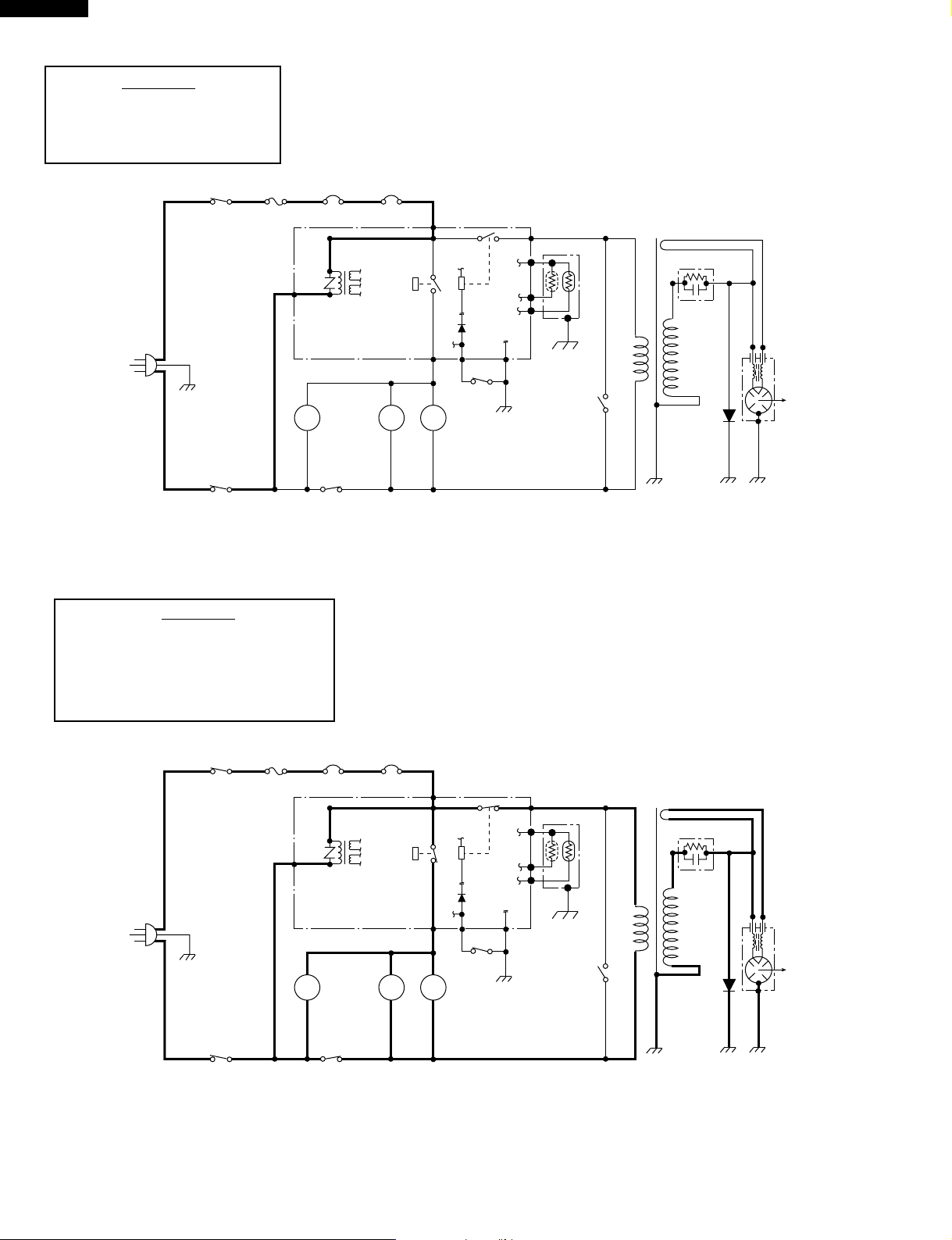
SCHEMATIC
NOTE: CONDITION OF OVEN
1. DOOR CLOSED.
2. HOME PAGE APPEARS ON
DISPLAY.
A3
THERMAL
CUT-OUT (OVEN)
CONTROL UNIT
120V AC
60 Hz
OUTER CASE
SWITCH
MONITOR
FUSE
OL FM
OUTER CASE
SWITCH
Figure O-1. Oven Schematic-Off Condition
SCHEMATIC
NOTE: CONDITION OF OVEN
1. DOOR CLOSED.
2. COOKING TIME PROGRAMMED.
3. VARIABLE COOKING CONTROL "100%".
4. "START" PAD TOUCHED.
OVEN
LAMP
SECONDARY
INTERLOCK
SWITCH
THERMAL
CUT-OUT (MG.)
(RY-1)
TTM
TURN-
TABLE
MOTOR
COM.
(RY-2)
FAN
MOTOR
BAA1
PRIMARY
INTERLOCK
RELAY
DOOR
SENSING
SWITCH
AH SENSOR
POWER
TRANSFORMER
CAPACITOR
0.94µF
RECTIFIER
MAGNETRON
N.O.
F3
F2
F1
MONITOR
SWITCH
120V AC
60 Hz
OUTER CASE
SWITCH
OUTER CASE
SWITCH
A3
THERMAL
CUT-OUT (OVEN)
CONTROL UNIT
MONITOR
FUSE
OL FM
OVEN
LAMP
SECONDARY
INTERLOCK
SWITCH
THERMAL
CUT-OUT (MG.)
(RY-1)
TTM
TURN-
TABLE
MOTOR
COM.
(RY-2)
BA
A1
FAN
MOTOR
PRIMARY
INTERLOCK
RELAY
DOOR
SENSING
SWITCH
N.O.
F3
F2
F1
MONITOR
SWITCH
Figure O-2. Oven Schematic-Cooking Condition
AH SENSOR
POWER
TRANSFORMER
CAPACITOR
0.94µF
RECTIFIER
MAGNETRON
2
Page 5

COMPONENT REPLACEMENT AND ADJUSTMENT PROCEDURE
CAUTION: DISCONNECT OVEN FROM POWER SUPPLY BEFORE REMOVING OUTER CASE.
DISCHARGE HIGH VOLTAGE CAPACITOR BEFORE TOUCHING ANY OVEN COMPONENTS OR WIRING
AFTER REMOVING OUTER CASE.
WARNING FOR WIRING
R-390Aw
R-390AK
To prevent an electric shock, take the following manners.
1. Before wiring,
1) Disconnect the power supply.
2) Open the door and wedge the door open.
3) Discharge the high voltage capacitor and wait for 60
seconds.
2. Don’t let the wire leads touch to the following parts;
1) High voltage parts:
Magnetron, High voltage transformer, High voltage
capacitor and High voltage rectifier assembly.
2) Hot parts:
Oven lamp, Magnetron, High voltage transformer
and Oven cavity.
COOLING FAN MOTOR REMOVAL
REMOVAL
1. Disconnect oven from power supply and remove outer
case.
2. Discharge high voltage capacitor.
3. Disconnect the wire leads from the fan motor.
4. Remove the magnetron from the waveguide flange,
referring to "MAGNETRON REMOVAL".
5. Release the snap of the main wire harness from the fan
duct.
6. Remove one (1) screw holding the fan duct assembly to
oven cavity.
7. Release the main wire harness from the hole of the fan
duct.
8. Release the fan duct from the waveguide flange.
9. Release the fan duct assembly from the oven cavity.
10.Remove the fan blade from the fan motor shaft according
the following procedure.
1) Hold the edge of the rotor of the fan motor by using a pair
of groove joint pliers.
CAUTION:
* Make sure that any pieces do not enter the gap
between the rotor and the stator of the fan motor
because the rotor is easily shaven by pliers and
metal pieces may be produced.
* Do not touch the pliers to the coil of the fan motor
because the coil may be cut or injured.
* Do not disfigure the bracket by touching with the
pliers.
2) Remove the fan blade from the shaft of the fan motor by
pulling and rotating the fan blade with your hand.
3) Now, the fan blade will be free.
CAUTION:
* Do not reuse the removed fan blade because the
hole (for shaft) may be larger than normal.
3) Sharp edge:
Bottom plate, Oven cavity, Waveguide flange,
Chassis support and other metallic plate.
4) Movable parts (to prevent a fault)
Fan blade, Fan motor, Switch, Switch lever, Open
button.
3. Do not catch the wire leads in the outer case cabinet.
4. Insert the positive lock connector certainly until its pin
is locked. And make sure that the wire leads should not
come off even if the wire leads is pulled.
5. To prevent an error function, connect the wire leads
correctly, referring to the Pictorial Diagram.
11.Remove the two (2) screws holding the fan motor to the
fan duct.
12.Now, the fan motor is free.
INSTALLATION
1. Install the fan motor to the fan duct with the two (2)
screws.
2. Install the fan blade to the fan motor shaft according the
following procedure.
1) Hold the center of the bracket which supports the shaft
of the fan motor on the flat table.
2) Apply the screw lock tight into the hole (for shaft) of the
fan blade.
3) Install the fan blade to the shaft of fan motor by pushing
the fan blade with a small, light weight, ball peen hammer
or rubber mallet.
CAUTION:
* Do not hit the fan blade strongly when installed
because the bracket may be disfigured.
* Make sure that the fan blade rotates smooth after
installation.
* Make sure that the axis of the shaft is not slanted.
3. Catch three holes of fan duct on three tabs of the
waveguide flange.
4. Install the fan duct assembly to the oven cavity with the
one (1) screw.
5. Insert the snap of the main wire harness to the hole of the
fan duct and insert the main wire harness into the hole of
the fan duct.
6. Install the magnetron and the chassis support to the
oven cavity, referring to "Re-install of MAGNETRON
REMOVAL".
7. Connect the wire leads to the fan motor, referring to the
pictorial diagram.
3
Page 6

R-390Aw
R-390AK
Coil
Groove joint pliers
Stator
Gap
Bracket
Rotor
Shaft
Axis
Stator
Rotor
Side ViewRear View
DOOR REPLACEMENT
REMOVAL
1. Disconnect oven from power supply.
2. Push the open button and open the door slightly.
3. Insert an putty knife (thickness of about 0.5mm) into the
gap between the choke cover and door frame as shown
in Figure C-7 to free engaging parts.
4. Pry the principles of the lever and lift up the choke cover
by inserting a putty knife as shown Figure C-7.
5. Release choke cover from door panel.
6. Now choke cover is free.
7. Release two (2) pins of door panel from two (2) holes of
upper and lower oven hinges by lifting up.
8. Now, door assembly is free from oven cavity.
1
Choke Cover
11
10
9
13
12
7
8
Figure C-7. Door Disassembly
9. Release door panel from seven (7) tabs of door frame by
sliding door panel downward.
10.Now, door panel with sealer film is free.
11.Tear sealer film from door panel.
12.Now, door panel is free.
13.Slide latch head upward and remove it from door frame
with releasing latch spring from door frame and latch
head.
14.Now, latch head and latch spring are free.
15.Remove door screen from door frame by releasing two
(2) tabs.
16.Now, door screen is free.
RE-INSTALL
1. Re-install door screen to door frame by fitting two (2) tabs
of door frame to two (2) holes of door screen.
6
2
3
4
5
Door Frame
Putty Knife
Shaft
These are the position
where should be
pinched with pliers
Table
Center of
bracket
2. Re-install the latch spring to the latch head. Re-install the
latch spring to the door frame. Re-install latch head to
door frame.
3. Re-install door panel to door frame by fitting seven (7)
tabs of door frame to seven (7) holes of door panel.
4. Hold the door panel to the door frame by sliding the door
panel upward.
5. Put sealer film on door panel. Refer to "Sealer Film"
about how to handle new one.
6. Catch two (2) pins of door panel on two (2) hole of upper
and lower oven hinges.
7. Re-install choke cover to door panel by pushing.
Note: After any service to the door;
(A) Make sure that door sensing switch and secondary
interlock switch are operating properly. (Refer to
chapter "Test Procedures".).
(B) An approved microwave survey meter should be
used to assure compliance with proper microwave
radiation emission limitation standards.
After any service, make sure of the following :
1. Door latch heads smoothly catch latch hook through
latch holes and that latch head goes through center of
latch hole.
2. Deviation of door alignment from horizontal line of cavity
face plate is to be less than 1.0mm.
3. Door is positioned with its face pressed toward cavity
face plate.
4. Check for microwave leakage around door with an
approved microwave survey meter. (Refer to Microwave
Measurement Procedure.)
Note: The door on a microwave oven is designed to act as
an electronic seal preventing the leakage of
microwave energy from oven cavity during cook
cycle. This function does not require that door be airtight, moisture (condensation)-tight or light-tight.
Therefore, occasional appearance of moisture, light
or sensing of gentle warm air movement around
oven door is not abnormal and do not of themselves,
indicate a leakage of microwave energy from oven
cavity.
4
Page 7

R-390Aw
LCD
vessel
tab
IC2
IC1
C11
LCD
vessel
tab
R-390AK
Door assemby
Figure C-8. Door Replacement
Pin
Pin
Lower
oven
hinge
Upper oven hinge
Lower oven
hinge
Choke cover
Installation
1. Put the adhesive tape on the backing film of the sealer
film as shown in Fig. C-9.
2. Tear the backing film by pulling the adhesive tape.
3. Put the pasted side of the sealer film on the door panel
DISPLAY UNIT LAMPS REMOVAL
SEALER FILM
Sealer film
Backing film
Adhesive tape
Figure C-9. Sealer film
1. Disconnect oven from power supply and remove outer
case.
2. Discharge high voltage capacitor.
3. Remove the control panel assembly from the oven,
referring to "CONTROL PANEL ASSEMBLY REMOVAL".
4. Remove the five (5) screws holding the display unit and
the power unit to the control panel frame.
5. Remove the display unit and the power unit from the
control panel frame.
6. Remove the solder holding the tab (near capacitor C11)
of LCD vessel to the printed wiring board.
7. Make the four (4) tabs of LCD vessel straight.
8. Release the LCD vessel from the printed wiring board.
9. Now, the two (2) lamps LMP1 and LMP2 can be found.
10.Remove the solder holding the lamps LMP1 and LMP2
to the printed wiring board.
11.Now, the lamps LMP1 and LMP2 are free.
Figure C-10. Back side view of display unit
5
Page 8

R-390Aw
R-390AK
1
A
B
AC120V
60Hz
C
2
A 3
VRS1
a
b
d
c
1
2
(J1)
3
T1
3
D3
4
D4
RY1
D1-D4
11ES1
D1
D2
45
C 9
C 8
+
–
C1 0.1µ/50v
ZD2
R3 1.3k
ZD1
C2 1000µ/35v
R1 2.4k
2SB1238
R2
82
1w
HZ20-2
Q2
2SB1238
Q1
R6
82
1w
HZ16-3
C3 0.1µ/50v
SP1
+
–
C 7
C4 10µ/35v
–
+
C5
10µ/35v
C 2
C 1
6
A
B
C
D
TURNTABLE
MOTOR
OVEN LAMP
FAN
MOTOR
MICRO
E
F
G
A 1
N.O.
COM
RY2
D7
R4 1.3k
R5 3.3k
C 3
C 6
D
C10
C 4
D8
C 5
E
Figure S-4. Display Unit Circuit
C11
Q3 KRC243M or
DTD143ES
F
+
C6 10µ/35v
–
SH-B
SH-A
G
H
1
NOTE
2
: IF NOT SPECIFIED, 1/4w ± 5%
: IF NOT SPECIFIED, 1SS270A
Figure S-2. Power Unit Circuit
3
45
6
H
6
Page 9

R-390Aw
R-390AK
1
A
C134
C133
C132
C131
C130
0.1µ/25v x 5
2k
R130
2k
R131
B
C
R136 10kF
Q141
D
4.7k
R142
2SA1036K
LMP1LMP2
R141 2.2k
LD1
LD2
KRA101S
Q140
E
50v
0.01µ
C12
CF1
CSTCS12.00MT
C16 0.1µ/25v
Cd
VSS
5
VC
IC5
M51953A
VCC
NC
+
NC
NC
NC 148
C11 47µ/16v
–
C10 0.01µ/50v
HZM5.6NB 2
ZD10
Q1
2SB1238
R10 4.7k
C17 0.1µ/50v
C14 0.1µ/50v
F
G
6.2k
2k
R133
R132
R138 22kF
5G39B332J
TH1
LD3
LD4
4.7k x 4
(J17)
(J15)
(J13)
(J11)
R11 470 1/2w
Q12
KRA101S
2
2k
2k
R135
R134
43kF
R137
7
1C4 (1/2)
NJM062M
1/4w
750
(J18)
4.7k (J19)
R140
0.1µ/25v
C135
LD5
0.01µ/50v
C13
R12 4.7k
+
-
5
6
LD6
(J16)
(J14)
(J12)
(J10)
0.1µ/25v
C18
43
V6R
VEE2
VMH2
VMH3
VMIL3
VMIL2
51
Ø
C15
0.1µ/25v
80
C52-C53 0.01µ/50v x 2
D50
1SS181
R62-R64 120 1/2w x 3
R62
R63 R64
3
HD6610B(LCD Driver)
M
RS
CS
RD
CO
WR
M/S
V1R
DB0
DB1
DB2
DB3
DB4
DB5
VCC4
VCC3
A 8
A18
A17
A14
A13
VCC
32
A 7
A 6
A16
A15
A12
OE1 1
50
A 9
A 8
A 7
A 6
A11
A10
VSS
A12
A13
A14
A15
A16
A17
A18
A19
VSS
WAIT
P61
P62
STBY
BES
NMI
VSS
EXTAL
XTAL
VCC
P63
RD
HWR
P66
MD0
MD1
MD2
AVCC
VREF
AN0
AN1
AN2
AN3
AN4
AN5
AN6
DA1
81
C53
C52
0.015µ/50v
C51
1
8
IC4
-
+
3
0.1µ/25v
C50
3.57kD
R61
R54
3.32kD
C30 0.01µ/50v
R30 4.7k
DB6
DB7
OE
A 9
A11
A 5
A 4
A 3
A 5
A 4
A 3
IC1
IRQ0
IRQ1
AVSS
R53
47k
R52
10k
4
2
IC4 (1/2)
R50 1.8kG
FLM
CE
D 7
D 6
D 5
A10
IC1 IZA807DR
A 2
A 1
A 0
D 0
D 1
A 2
A 1
A 0
D15
VCC
IZA806DR
PA0
CS1
CS0
VSS
IRQ2
R56 620kJ
R55 47k
R51 360kG
NJM062M
R31
15k
CL1
0.1µ/25v
C122
D 4
D 3
16 17
D 2
GND
D14
D13
D12
PA1
PA2
PA3
R57 300kG
R58 150kF
R59 75kF
45
(100 x 65 DOTS)
LCD A057DR
1
V3
V4
V1L
V6L
VEE1
VML1
VCC2
VCC1
OSC2
OSC1
GND3
GND2
GND1
D 9
D 8
D 7
D 6
D 5
P44
VSS
P43
P42
P41
P40
P95
P94
P93
P92
P91
P90
VSS
RES0
P87
P86
P85
P84
P83
VCC
A20
PA6
TIOCA4
TIOCD3
TIOCA3
1 30
VMH1
C121 0.1µ/25v
C120 0.1µ/25v
R120 4.7k
50v
0.01µ
C110
4.7k
R110
Q160
KRA101S
A 2
A 1
SCL
TEST
R101 4.7k
R84 15k
Q40
KRA101S
A 0
1
8
VCC
SELECT 2
R85 15k
C20
R102 4.7k
SELECT 1
(TOP)
0.1µ/25v
Q20
KRA101S
CHECKER
–
+
C100 0.01µ/50v
SELECT 4
(BOTTOM)
SELECT 3
Q41
KRC101S
C101 10µ/35v
BOOKMARK
SW18 SW19SW16 SW17
SW20 SW21
R79 15k
R78 15k
R77 15k
R76 15k
R75 15k
R74 15k
R73 15k
R72 15k
R160 4.7k
4
5
1C3
CAT24C01J or CAT24C02J
GND VSS
R100 4.7k
R81 100k
R82 100k
R83 100k
R80 100k
Q42
KRA101S
TEST2
TEST1
RESET
C123 0.1µ/50v
D11
D10
PA4
PA5
R60 37.4kF
31
100
R103 150 1/2w
(FORWARD)
BOOKMARK
(BACK)
D20
1SS181
6
A
B
: IF NOT SPECIFIED, 1/16w ± 5%
NOTE
C
D
G 1
G 2
G 3
G 4
G 5
CN-G
G 6
G 7
G 8
E
C22 0.01µ/50v
F
Q22
KRA105S
G
C 8
GND
C 7
VA
H
1
C 6
INT
C10
BACK
LIGHT
AH
SENSOR
2
F 1
F 2
F 3
CN-F
3
7
C 2
BUZZER
(EN.)
C 1
BUZZER
C 3
OVEN LAMP
FAN MOTOR
TURNTABLE
MOTOR
C 4
MICRO
C11
DOOR
45
C 5
C 9
(BROWNER)
N.C
H
6
Page 10

R-390Aw
R-390AK
1
A
B
C
D
2
SW16
1
3
3
LD1
AK
LMP1
AK
LD2
C123
LD3
AK
2
5
4
R140
11 1
R143
LMP2
TH1
ZD10
Q141
R10
K
AK
R142
R141
AK
A
R11
A
C17
45
LD6
LD5
LD4
CN-C
1
3
K
SW17
2
5
4
C18
SW19
1
3
1
1
3
3
SW21
SW20
2
5
4
2
5
43
2
5
4
1
SW18
245
6
A
B
C
D
E
F
G
J14
J15
J17
J16
C52
R53
R51R52
1
8
45
C135
D50
KK
R54
R55
R56
R58
R60
R62
R63
R64
C50
R50
IC4
C51
R61
TP15
+
C11
Q42
TP21
TP22
Q41
TP20
Front side
J12
J13
J11
J10
R137
R138
A
81 50
C53
R57
100
R59
C30
R31
Q40
TP23
3
CN-F
R136
80
Q20
1
TP14
R30
C10
C15
C20
Q160
1
TP36
C121
CF1
TP35
Q1
1
IC5
C120
R65
T1
R160
1
4
CN-C
R120
TP16
R64
R73
T2
TP6
R72
TP7
C13
R12
CEB
TP29
R75
Q12
R100
R101
R74
TP24
C16
TP25
R13
C12
E
R135
LCD
R110
C110
TP34
8
TP9
J19
5
Q140
J18
32
51
C122
R133
R132
R131
R130
R134
C134
C133
C132
C131
C130
17
F
D20
C101
C100
TP18
Q22Q23
161
+
TP13
R103
G
TP19
C22
C23
TP8
CN-G
8
R79
C14
R93
R92
R78
R77
R91
R90
R76
TP11
TP1
TP31
TP28
31
TP10
4
TP17
TP26
IC1
1
TP27
R102
IC3
TP33
TP32
A
TP12
TP30
11
IC2
8
5
TP5
K
K
1
H
1
Back side
Figure S-6. Printed Wiring Board of Display Unit
2
3
45
8
H
6
Page 11

R-390Aw
R-390AK
PARTS LIST FOR R-390AW
REF. NO. PART NO. DESCRIPTION Q'TY CODE
ELECTRIC PARTS
1- 1 QSW-MA110WRE0
1- 2 QFSHDA009WRE0 Fuse holder 1 AH
1- 3 FFS-BA012WRK0 Monitor fuse and monitor switch assembly 1 AH
1- 4 RTHM-A078WRE0 Thermal cut-out 125 deg. 1 AL
1- 5 FACCDA075WRE0 Power supply cord 1 AN
1- 6 FH-DZA075WRK0 High voltage rectifier assembly 1 AS
1- 7 RC-QZA211WRE0 High voltage capacitor 1 AW
1- 8 RV-MZA267WRE0 Magnetron 1 BL
1- 8 RV-MZA197WRE0 Magnetron (Interchangeable) 1 BN
1- 8 RV-MZA271WRE0 Magnetron (Interchangeable) 1 BL
1- 9 RMOTEA338WRE0 Fan motor 1 AV
1- 9 RMOTEA277WRE0 Fan motor (Interchangeable) 1 AX
1-10 QSOCLA021WRE0 Oven lamp socket 1 AH
1-11 RLMPTA030WRE0 Oven lamp 1 AF
1-12 RMOTDA161WRE0 Turntable motor 1 AU
1-13 RTHM-A079WRE0 Thermal cut-out 95 deg. 1 AL
1-14 RTRN-A512WRE0 Power transformer 1 BM
1-14 RTRN-A525WRE0 Power transformer (Interchangeable) 1 BM
1-15 FDTCTA176WRK0 AH. sensor assembly 1 AV
2- 1 GCABUA620WRP0 Outer case cabinet 1 AZ
2- 2 GDAI-A261WRW0 Bottom plate left 1 AP
2- 3 GDAI-A286WRW0 Bottom plate right 1 AN
2- 4 GLEGPA019WRE0 Foot 2 AD
2- 5 GLEGPA067WRF0 Leg 1 AE
3- 1 CPWBFA742WRK0 Power unit 1 BE
3- 1A QCNCMA394DRE0 2-pin connector (CN-A) 1 AD
3- 1B QCNCMA432DRE0 11-pin connector (CN-C) 1 AF
3- 1C FW-VZA195DRE0 Switch harness A (SN-A) 1 AD
3- 1D FW-VZA197DRE0 Switch harness B (SN-B) 1 AD
C1 RC-KZA087DRE0 Capacitor 0.1uF 50V 1 AB
C2 VCEAB31VW108M Capacitor 1000uF 35V 1 AF
C3 RC-KZA087DRE0 Capacitor 0.1uF 50V 1 AB
C4-6 VCEAB31VW106M Capacitor 10uF 35V 3 AA
D1-4 VHD11ES1///-1 Diode (11ES1) 4 AB
D7-8 VHD1SS270A/-1 Diode (1SS270ATA) 2 AA
Q1-2 VS2SB1238//-3 Transistor (2SB1238) 2 AA
Q3 VSKRC243M//-3 Transistor (KRC243M) 1 AB
R1 VRD-B12EF242J Resistor 2.4k ohm 1/4W 1 AA
R2 VRS-B13AA820J Resistor 82 ohm 1W 1 AA
R3-4 VRD-B12EF132J Resistor 1.3k ohm 1/4W 2 AA
R5 VRD-B12EF332J Resistor 3.3k ohm 1/4W 1 AA
R6 VRS-B13AA820J Resistor 82 ohm 1W 1 AA
RY1 RRLY-A080DRE0 Relay (OJ-SH-124LM) 1 AG
RY2 RRLY-A076DRE0 Relay (OMIF-S-124LM) 1 AK
SP1 RALM-A014DRE0 Buzzer (PKM22EPT-THAI) 1 AG
T1 RTRNPA113DRE0 Transformer 1 AT
VRS1 RH-VZA032DRE0 Varistor (10G471K) 1 AE
ZD1 VHEHZ163///-1 Zener diode (HZ16-3) 1 AC
ZD2 VHEHZ202///-1 Zener diode (HZ20-2) 1 AB
3- 2 DPWBFB691WRK0 Display unit 1 BW
3- 2- 1 RH-HZA012DRE0 Thermistor TH1 1 AL
3- 2- 2 RH-TZA120DRE0 Transistor (KRA101S). Q12,Q20,Q40,Q42,Q140,Q160 6 AE
3- 2- 3 RH-TZA119DRE0 Transistor (KRC101S). Q41 1 AE
3- 2- 4 RH-TZA127DRE0 Transistor (KRA105S). Q22 1 AE
3- 2- 5 RH-DZA074DRE0 Diode (1SS181). D20,D50 2 AE
3- 2- 6 RH-DZA076DRE0 Zener diode (HZM5.6NB2). ZD10 1 AE
3- 2- 7 RLMPHA046DRE0 Lamp (LMP1,LMP2) 2 AM
3- 2- 8 RH-TZA130DRE0 Transistor (2SA1036K). Q141 1 AH
3- 2- 9 QSW-PA027DRE0 Tact switch (SW16-SW21) 6 AG
3- 3 DPWBFB688WRU0 Switch unit 1 AP
3- 3- 1 FW-VZA219DRE0 Lead wire harness (CN-G) 1 AK
3- 3- 2 QSW-PA016DRE0 Tact switch (SW1-SW15) 15 AB
3- 4 GMADIA108WRR0 Display window 1 AF
3- 5 HPNLCB416WRR0 Control panel frame 1 AV
3- 6 JBTN-B029WRF0 Open button 1 AG
2nd interlock switch, door sensing switch and outer case switches
4AK
CABINET PARTS
CONTROL PANEL PARTS
9
Page 12

R-390Aw
R-390AK
REF. NO. PART NO. DESCRIPTION Q'TY CODE
3- 7 JBTN-B081WRF0 Book mark button 1 AF
3- 8 JBTN-B080WRF0 Page button 1 AF
3- 9 JBTN-B079WRF0 Select button 1 AF
3- 10 JBTN-B078WRF0 Start button 1 AF
3- 11 MSPRCA050WRE0 Open button spring 1 AB
3- 12 MSPRCA104WRE0 Select button spring 1 AD
3- 13 XEPSD30P08XS0 Screw: 3mm x 8mm 9 AA
OVEN PARTS
4- 1 MLEVFA082WRE0 Actuator 1 AD
4- 2 PHOK-A104WRF0 Switch holder 1 AF
4- 3 PHOK-A095WRF0 Latch hook 1 AN
4- 4 LBNDKA099WRW0 Capacitor holder 1 AD
4- 5 NFANJA029WRE0 Fan blade 1 AL
4- 6 PDUC-A652WRP0 Fan duct 1 AU
4- 7 ************* Oven cavity (Not a replaceable part) 1BC
4- 8 LANGFA175WRP0 Chassis support 1 AX
4- 9 LANGQA452WRP0 Partition angle 1 AK
4-10 LANGQA454WRP0 MG thermo angle 1 AH
4-11 MLEVPA194WRF0 Switch lever 1 AG
4-12 NCPL-A045WRF0 Coupling 1 AH
4-13 PCUSGA385WRP0 Cushion 1 AK
4-14 PCOVPA275WRE0 Waveguide cover 1 AR
4-15 PCUSGA339WRP0 Cushion 1 AG
4-16 PCUSUA212WRP0 Cushion 1 AB
4-18 PCUSUA376WRP0 Cushion 1 AG
4-19 PCUSUA192WRP0 Cushion 1 AD
4-20 PCUSUA329WRP0 Cushion 1 AC
4-21 PCUSGA399WRE0 Cushion 1 AG
4-22 PPACGA084WRF0 TTM packing 1 AF
4-23 LANGTA338WRP0 Sensor mounting angle 1 AN
DOOR PARTS
5- 1 FDORFA318WRT0 Door panel 1 BE
5- 2 PSHEPA382WRE0 Sealer film 1 AH
5- 3 GWAKPA531WRR0 Door frame 1 AT
5- 4 HPNL-A663WRR0 Door screen 1 AL
5- 5 GCOVHA385WRF0 Choke cover 1 AG
5- 6 LSTPPA139WRF0 Latch head 1 AF
5- 7 MSPRTA084WRE0 Latch spring 1 AB
5- 8 PCUSUA481WRP0 Cushion 1 AB
5- 9 PCUSUA452WRP0 Cushion 1 AB
5-10 XCPSD40P08000 Screw : 4mm x 8mm 1 AA
5-11 XCPSD40P08WN2 Screw : 4mm x 8mm 1 AC
MISCELLANEOUS
6- 1 FROLPA079WRK0 Turntable support 1 AQ
6- 2 NTNT-A079WRE0 Turntable tray 1 AR
6- 3 FW-VZB572WRE0 Main wire harness 1 BC
6- 4 QW-QZA150WRE0 High voltage wire B 1 AF
6- 5 PZET-A012WRE0 Terminal insulator 1 AB
6- 6 TCAUAA166WRR0 DHHS caution label 1 AC
6- 7 TCAUAA200WRR0 Monitor caution label 1 AB
6- 8 TCADCA655WRR0 Instruction book 1 AY
6- 9 TLABMA550WRR0 Copyright label 1 AD
SCREWS,NUTS AND WASHERS
7- 1 XFPSD40P08K00 Screw : 4mm x 8mm 7 AA
7- 2 XFPSD30P06000 Screw : 3mm x 6mm 3 AA
7- 3 XHTSD40P08RV0 Screw : 4mm x 8mm 3 AA
7- 4 XHTSD40P12RV0 Screw : 4mm x 12mm 1 AA
7- 5 XOTSD40P12RV0 Screw : 4mm x 12mm 8 AA
7- 6 XOTSD40P12000 Screw : 4mm x 12mm 14 AA
7- 7 XOTSE40P08000 Screw : 4mm x 8mm 1 AA
7- 8 XOTSD40P14000 Screw : 4mm x 14mm 1 AA
10
Page 13

HOW TO ORDER REPLACEMENT PARTS
To have your order filled promptly and correctly, please furnish the following information.
1. MODEL NUMBER 2. REF. NO. 3. PART NO. 4. DESCRIPTION
Order Parts from the authrized SHARP parts Distributor for your area.
Defective parts required return should be returned as indicated in the Service Policy.
INFORMATION OF PARTS CHANGE FOR MODEL R-390AK
The following parts have been changed for the Base model R-390AK.
Interchangeability
A. OLD NEW B. OLD NEW C. OLD NEW D. OLD NEW
R-390Aw
R-390AK
REPLACEMENT PART NO.
REF.NO. DESCRIPTION
1- 5 Power supply cord FACCDA048WRE0 1 FACCDA075WRE0 1 A Sep./'97 AN
3- 2- 1 Thermistor TH1 Not listed RH-HZA012DRE0 1 C Nov./'97 AL
3- 2- 2 Transistor (KRA101S) Not listed RH-TZA120DRE0 6 C Nov./'97 AE
Q12,Q20,Q40,Q42,Q140,Q160
3- 2- 3 Transistor (KRC101S) Not listed RH-TZA119DRE0 1 C Nov./'97 AE
Q41
3- 2- 4 Transistor (KRA105S) Not listed RH-TZA127DRE0 1 C Nov./'97 AE
Q22
3- 2- 5 Diode (1SS181) Not listed RH-DZA074DRE0 2 C Nov./'97 AE
D20,D50
3- 2- 6 Zener diode (HZM5.6NB2) Not listed RH-DZA076DRE0 1 C Nov./'97 AE
ZD10
3- 2- 7 Lamp LMP1,LMP2 Not listed RLMPHA046DRE0 2 C Nov./'97 AM
3- 2- 8 Transistor (2SA1036K) Not listed RH-TZA130DRE0 1 C Nov./'97 AH
Q141
3- 2- 9 Tact switch Not listed QSW-PA027DRE0 6 C Nov./'97 AG
SW16-SW21
3- 3 Switch unit DPWBFB688WRK0 1 DPWBFB688WRU0 1 Misprint AP
4- 2 Switch holder PHOK-A098WRF0 1 PHOK-A104WRF0 1 A Jul./'97 AF
4- 17 Door stopper LSTPPA162WRF0 1 Deleted 0 D Sep./'97
5 Door assembly CDORFA772WRK0 1 Deleted 0 D Sep./'97
5- 1 Door panel FDORFA303WRT0 1 FDORFA318WRT0 1 D Sep./'97 BE
5- 5 Choke cover GCOVHA370WRF0 1 GCOVHA385WRF0 1 D Sep./'97 AG
6- 8 Instruction book TCADCA639WRR0 1 TCADCA655WRR0 1 C Nov./'97 AY
7- 5 Screw: 4mm X 12mm XOTSD40P12RV0 9 XOTSD40P12RV0 8 A Jun./'97 AA
7- 8 Screw: 4mm X 14mm Not listed XOTSD40P14000 1 C Jun./'97 AA
OLD No.
Q'ty NEW No.
Interchangeability
Q'ty
EFFECTIVE
FROM CODE
INFORMATION OF PARTS CHANGE FOR BOTH MODELS R-390AK AND R-390AW
The following parts will be changed for the both models R-390AK and R-390AW.
Q3 Transistor VSKRC243M//-3 1 VSDTD143ES/-3 1 A Dec./'97 AC
3- 2- 6 Zener diode ZD10 RH-DZA076DRE0 1 RH-DZA077DRE0 1 A Nov./'97
7- 2 Screw: 3mm X 6mm XFPSD30P06000 3 XHPSD30P06000 3 A Dec./'97 AA
11
Page 14

R-390Aw
R-390AK
1
OVEN AND CABINET PARTS
A
B
4-19
C
1-15
7-2
4-23
2
4-18
1-11
4-9
1-10
1-4
6-7
7-5
3
2-1
7-5
7-3
4-10
1-13
7-2
45
7-1
6-9
1-8
6-6
4-16
7-5
6
A
7-8
B
7-7
C
D
4-7
4-20
E
4-12
4-14
F
G
7-6
2-4
2-2
1-12
4-22
7-1
4-11
7-5
7-5
4-15
4-3
4-13
1-1
1-1
1-14
1-2
1-1
1-3
4-21
7-6
1-1
7-6
1-9
7-5
7-3
1-5
7-1
4-1
4-4
4-2
7-4
4-6
4-5
1-7
1-6
7-1
7-6
4-8
6-2
7-3
D
E
F
G
7-6
H
1
2-5
7-6
2
7-6
7-6
7-6
7-6
2-4
3
12
2-3
6-1
7-6
45
H
6
Page 15

R-390Aw
R-390AK
1
2
3
CONTROL PANEL, DOOR AND MISCELLANEOUS PARTS
A
3 - 5
3 - 4
3 - 8
B
3 - 7
3-12
C
3 - 6
3-11
3-10
3-3-1
3-3-2
3 - 9
45
3 - 2
3-2-7
3 - 1
3 - 3
3-13
3-13
6
A
3-13
3-2-9
B
3-13
C
D
E
F
G
5-3
5-4
5-8
5-1
5-7
5-9
5-11
5-2
5-5
D
5-10
E
F
5-6
G
H
Actual wire harness may be different from illustration.
1
6-3
2
(HIGH VOLTAGE TRANSFORMER)
6-4
6-5
3
13
(CAPACITOR)
45
H
6
Page 16

R-390Aw
R-390AK
1
A
PACKING AND ACCESSORIES
B
C
D
E
INTO THE
F
OVEN CAVITY
2
DOOR PROTECTION SHEET
SPADPA204WRE0
6- 8 INSTRUCTION BOOK
& PRINTING MATTER
6- 2 TURNTABLE TRAY
6- 1 TURNTABLE SUPPORT
TRAY PACK
SPADFA397WRE0
3
45
CABINET COVER (R-390AK only)
SPAKHA003WRE0
PLASTIC BAG
SSAKHA034WRE0
TOP PAD ASSEMBLY
FPADBA341WRK0
BOTTOM PAD ASSEMBLY
FPADBA342WRK0
6
A
B
C
D
E
F
G
H
1
Not replaceable items.
2
3
45
COPYRIGHT © 1997 BY SHARP CORPORATION
ALL RIGHTS RESERVED.
No part of this publication may be reproduced, stored in a retrieval systems, or transmitted in any form or by any means, electronic, mechanical, photocopying, recording, or otherwise, without prior written permission of the publisher.
PACKING CASE
R-390AW: SPAKCC995WRE0
R-390AK: SPAKCC927WRE0
G
H
6
14
'97 SHARP CORP. (5K2.770E) Printed in U.S.A
 Loading...