

Page 1
MANUEL DE SER VICE
S03927R212EHW/F
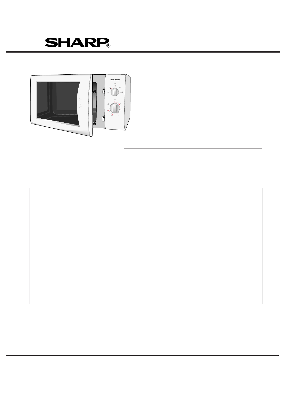
FOUR A MICRO-ONDES
R- 212(W)N
R-212(W/BL)E
R-202
R-212(W/BL/G/Y)
R-212(W/BL/G/Y)D
Dans l’intérêt des utilisateurs et pour leur sécurité, le four devra être réparé
et remis dans son état initial en utilisant exclusivement les pièces identiques
à celles qui ont été spécifiées.
TABLE DES MATIERES
Page
ATTENTION, RADIATION DES MICRO-ONDES...................................... COUVERTURE INTERIEURE
AVERTISSEMENT....................................................................................................................................1
REPARATION.......................................................................................................................................... 2
DESCRIPTION DU PRODUIT ..................................................................................................................3
INFORMATION GENERALE ....................................................................................................................3
VUE APPARENTE....................................................................................................................................4
ORDRE DES OPERATIONS ....................................................................................................................5
FONCTIONS DES COMPOSANTS IMPORTANTS ................................................................................ 6
GUIDE DE DEPISTAGE DES PANNES...................................................................................................7
PROCEDURE DE TEST.......................................................................................................................... 8
ENSEMBLE NUMERIQUE-ANALOGIQUE ............................................................................................14
REMPLACEMENT DES COMPOSANTS ET PROCEDURE DE REGLAGE ........................................ 18
MESURE DES MICRO-ONDES ............................................................................................................ 23
DONNEES DE TEST EN UN COUP D’OEIL......................................................................................... 24
SCHEMA.................................................................................................................................................24
DIAGRAMME SCHEMATIQUE ............................................................................................................. 25
CIRCUIT DU PANNEAU DE COMMANDE ............................................................................................26
SCHEMA DE CABLAGE.........................................................................................................................27
LISTE DES PIECES .............................................................................................................................. 28
SHARP CORPORATION
Page 2

ATTENTION
RADIATION DES MICRO-ONDES
Le personnel de dépannage ne devra pas s’exposer à l’énergie des micro-ondes qui peut
être émise
du magnétron ou d’autres dispositifs produisant des micro-ondes s’ils ne sont pas utilisés
ou branchés correctement. Tous les raccordements d’entrées et de sorties des microondes, des guides d’ondes, des brides et des garnitures doivent être sûrs. Ne jamais
faire marcher l’appareil sans une charge absorbant l’énergie des micro-ondes.
Ne jamais regarder dans une antenne ou un guide d’ondes ouvert lorsque l’appareil est
sous tension.
Page 3
MANUEL DE SERVICE
REPARATION
MANUEL DE SERVICE
R-212(W)N/ R-212(W/BL)E/ R-212(W/BL/G/Y)/ R-212(W/BL/G/Y)D
INFORMATION GENERALE IMPORTANTE
Ce manuel a été rédigé à l’intention du personnel de dépannage de
la société Sharp Corp. et contient les renseignements nécessaires
pour le fonctionnement et l’entretien de l’appareil.
Il est recommandé à ce personnel de dépannage de lire attentivement
la totalité de ce manuel afin d’être qualifié pour donner entière
satisfaction aux clients.
AVERTISSEMENT
Remarque: Les pièces marquées “*” sont utilisées à des
tensions supérieures à 250 V. (Liste des pièces)
Anm: Delar märket med “*” har en spänning
överstigande 250 V.
Huom: Huolto-ohjeeseen merkitty “tähdella” osat
joissa jännite on yli 250 V.
Bemerk: Deler som er merket “asterisk” er utsatt for
spenninger over 250 V til jord.
Bemærk: “Dele mærket med stjerne benyttes med
højere spænding end 250 volt.
AVERTISSEMENT
DESCRIPTION DU PRODUIT
INFORMATION GENERALE
VUE APPARENTE
ORDRE DES OPERATIONS
FONCTIONS DES
COMPOSANTS IMPORTANTS
GUIDE DE DEPISTAGE DES PANNES ET PROCEDURE DE TEST
GUIDE DE DEPISTAGE DES
PANNES
REMPLACEMENT DES
COMPOSANTS ET PROCEDURE
DE REGLAGE
Ne jamais faire fonctionner le four tant que l’on n’est pas assuré des
points suivants.
(A) La porte est fermée hermétiquement.
(B) Les charnières et les supports de porte ne sont pas défectueux.
(C) La garniture de porte n’est pas endommagée.
(D) La porte n’est pas déformée ou gondolée.
(E) Il n’y a pas d’autres détériorations visibles du four.
Les travaux de réparation et d’entretien ne devront être effectués
que par un personnel de dépannage qualifié.
Le retrait du capot extérieur expose à des potentiels supérieurs à
250 V.
Toutes les pièces marquées “∆” sur la liste des pièces risquent
de provoquer d’elles-mêmes une exposition excessive aux
radiations des micro-ondes ou lorsqu’elles sont endommagées,
desserrées ou retirées.
SHARP CORPORATION
OSAKA, JAPAN
1
MESURE DES MICRO-ONDES
DONNEES DE TEST EN UN
COUP D’OEIL
SCHEMA DE CABLAGE
LISTE DES PIECES
Page 4

REPARATION
AVERTISSEMENT POUR LE PERSONNEL DE DEPANNAGE
F Les fours à micro-ondes ont des circuits qui peuvent produire de très hautes tensions et courants. Eviter le contact
avec les pièces suivantes.
Condensateur haute tension, transformateur de puissance, magnétron, ensemble de redresseur haute tension,
faisceau de câbles haute tension.
RAPPEL DE VERIFICATION
1) Débrancher l’alimentation.
2) Débloquer la porte et la maintenir ouverte avec une cale.
3) Décharger le condensateur haute tension.
AVERTISSEMENT:
Le condensateur haute tension reste chargé environ 60
secondes après que le four ait été mis hors circuit. Attendre
60 secondes et court-circuiter ensuite la connexion du
condensateur haute tension (c’est-à-dire, du conducteur
de connexion du redresseur haute tension) contre le châssis
à l’aide d’un tournevis isolé.
Sharp recommande de débrancher le cordon d’alimentation
chaque fois qu’on cherche la cause de la panne. Dans
certains cas, il sera nécessaire de raccorder le cordon
d’alimentation après la dépose du boîtier extérieur, dans ce
cas effectuer les vérifications
conducteurs au primaire du transformateur de puissance.
S’assurer que ces conducteurs restent isolés des autres
composants et du châssis du four. (Utiliser un ruban isolant
si nécessaire.) Lorsque l’essai est terminé, effectuer les
vérifications
transformateur de puissance.
3D et raccorder les fils au primaire du
CONTRE LA CHARGE DU
CONDENSATEUR HAUTE TENSION
3D
3D et débrancher ensuite les
RAPPEL DE VERIFICATION 4R
1) Raccorder tous les fils retirés des composants pendant l’essai.
2) Remettre le boîtier extérieur en place (coffret).
3) Raccorder le cordon d’alimentation.
4) Redémarrer le four. Vérifier toutes les fonctions.
Les fours à micro-ondes ne doivent pas marcher à vide.
Pour tester la présence d’énergie de micro-ondes dans
une cavité, placer une tasse d’eau froide sur le plateau
tournant du four, fermer la porte, régler le niveau de puissance sur HIGH et régler la minuterie du four à micro-ondes
sur (2) minutes. Lorsque les deux minutes sont écoulées
(minuterie à zéro), vérifier attentivement si l’eau est chaude
maintenant. Si l’eau reste froide, effectuer les vérifications
3D et réexaminer les connexions au composant en cours
d’essai.
Lorsque tous les travaux de réparation sont terminés et
que le four est entièrement monté, la puissance requise
des micro-ondes doit être vérifiée et un test de recherche
de fuite de micro-ondes doit être effectué.
2
Page 5

DESCRIPTION DU PRODUIT
CARACTERISTIQUES TECHNIQUES
ITEM DESCRIPTION
Puissance requise 230 Volts
50 Hertz
Monophasé, 3 fils reliés à la masse
Consommation 1.24 kW
Puissance restituée 800 W nominal d’énergie de micro-ondes FR (mesurée par la méthode IEC
705) Fréquence de fonctionnement 2450 MHz
Dimensions du boîtier Largeur 449 mm
Hauteur 282 mm y compris les pieds
Profondeur 385 mm
Dimensions de la cavité de cuisson Largeur 287 mm
Hauteur 220 mm
Profondeur 311 mm
Diamètre du plateau tournant 272 mm
Commandes complémentaires Minuterie (0 - 30 minutes)
Puissance micro-ondes pour cuisson variable
Taux de répétition;
800 W (HIGH) ....... Pleine puissance pendant la durée de cuisson
560 W (MEDIUM HIGH) ................ env. 70% de pleine puissance
400 W (MEDIUM) .......................... env. 50% de pleine puissance
240 W (MEDIUM LOW) ................. env. 30% de pleine puissance
80 W (LOW)................................... env. 10% de pleine puissance
Poids Env. 13,3 kg net
INFORMATION GENERALE
ATTENTION
CET APPAREIL DOIT ETRE RELIE A LA MASSE
IMPORTANT
LES FILS DU CORDON SECTEUR SONT COLORES CONFORMEMENT AU CODE SUIVANT:
VERT ET JAUNE : MASSE
BLEU : NEUTRE
MARRON : PHASE
3
Page 6
VUE APPARENTE
FOUR
10
13
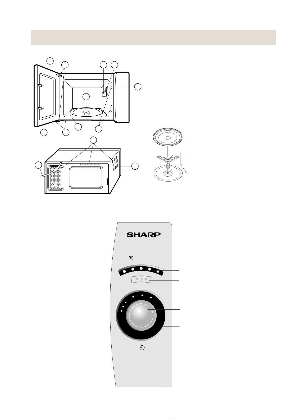
1. Porte
1
2
3 4
5
6
8
9
7
11
12
2. Charnières de la porte
3. Lampe du four
4. Cache de guide d’ondes
5. Panneau de commande
6. Accouplement
7. Ouvertures des loquets de porte
8. Cavité du four
9. Joints de la porte et surfaces de joints
10.Loquets de sécurité de la porte
11.Ouvertures de ventilation
12.Boîtier extérieur
13.Cordon d’alimentation
Plateau tournant
Support du plateau tournant
Emballage étanche
1. Placer le support du plateau tournant sur la base de la cavité
du four en le fixant à l’accouplement.
2. Ensuite, placer le plateau tournant sur le support du plateau
tournant.
PANNEAU DE COMMANDE DE TOUCHES AUTOMATIQUES
WATT
400
240 560
80
0
30
1
25
20
2
1415
3
13
12
4
11
5
10
800
6
7
8
9
Indicateur de puissance
Touche de niveau de puissance des micro-
ondes
Bouton de minuterie
Affichage lumineux
(0 - 30 minutes)
R-212
4
Page 7

ORDRE DES OPERATIONS
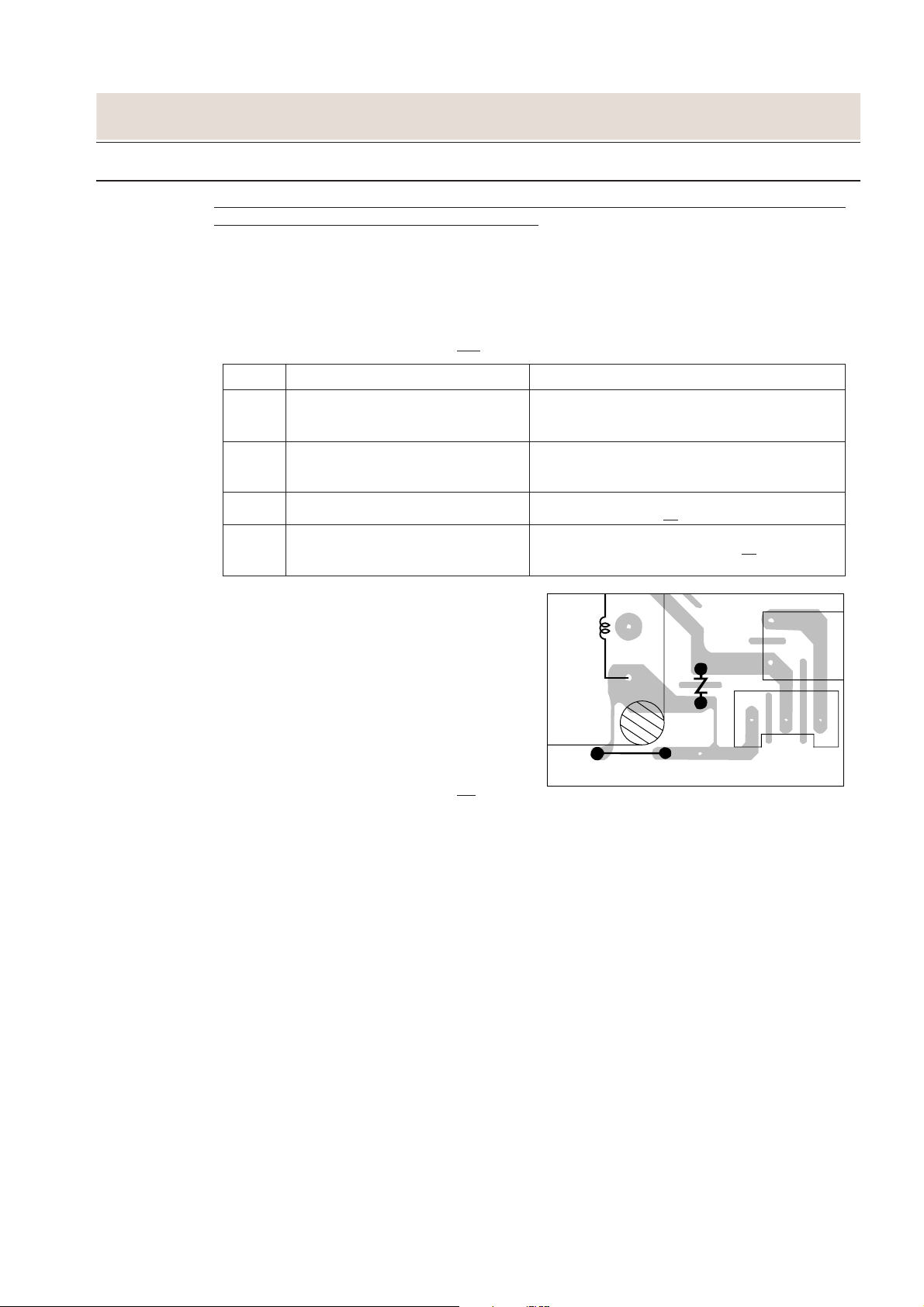
MODE OFF
La fermeture de la porte active les commutateurs de verrouillage de la porte (le commutateur du loquet de contrôle et le commutateur d’arrêt).
IMPORTANT
Lorsque le bouton de minuterie est sur “0”, le four est en
mode OFF.
Lorsque la porte du four est fermée, les contacts du commutateur de contrôle (COM - NC) doivent être ouverts.
Lorsque le four à micro-ondes est branché à une prise
murale (220 V 230 V 50 Hz), le filtre antiparasites et le panneau de commande sont amorcés.
Figure 0-1 de la page 24
MODE DE CUISSON AUX MICRO-ONDES
CUISSON PLEINE PUISSANCE (HIGH)
Lorsque la porte est fermée, les contacts (COM-NO) du
commutateur du loquet de contrôle (SW1) et du commutateur de contrôle (SW2) sont fermés. Lorsque la puissance des micro-ondes est mise sur la position 800 W par
pression sur la touche de niveau de puissance des microondes et le temps de cuisson est sélectionné en faisant
tourner le bouton de la minuterie, les éléments suivants
sont activés: le transformateur haute tension, le magnétron,
la lampe du four, le moteur du plateau tournant et le moteur du ventilateur.
Ordre de fonctionnement
Figure 0-2 à la page 24
COMPOSANTS CONNECTES RELAIS
Lampe du four, moteur du ventilateur,
moteur du plateau tournant RY1
Transformateur haute tension RY2
1. La tension de ligne est délivrée à l’enroulement primaire
du transformateur de puissance. La tension est convertie à 3,3 Volts CA environ sur l’enroulement du filament et à une haute tension de 2000 Volts CA environ sur l’enroulement secondaire.
2. La tension de l’enroulement du filament (3,3 Volts)
chauffe le filament du magnétron et la haute tension
(2000 Volts) est envoyée au circuit de doublage de
tension, où elle est doublée à une tension négative
d’environ 4000 Volts CC..
3. L’énergie de micro-ondes de 2450 MHz produite dans
le magnétron crée une longueur d’onde de 12,24 cm.
Cette énergie est envoyée à travers le guide d’onde
(chemin de transport) dans la cavité du four, où est
placé l’aliment à cuire.
4. Lorsque le temps de cuisson est augmenté, un signal
sonore est entendu et les relais
Les circuits qui alimentent la lampe du four, le transformateur haute tension, le moteur du ventilateur et le
moteur du plateau tournant sont coupés.
5. Lorsque la porte du four est ouverte pendant un cycle
de cuisson, les commutateurs se placent dans les po-
sitions suivantes.
COMMUTATEUR CONTACT LA CUISSON
Commutateur COM-NO Ouvert Fermé
du loquet de contrôle
Commutateur COM-NO Ouvert Fermé
de contrôle COM-NC Fermé Ouvert
Commutateur d’arrêt COM-NO Ouvert Fermé
RY1+RY2 sont ouverts.
CONDITION
PENDANT PORTE
(PAS DE CUISSON)
Les circuits qui alimentent le transformateur haute
tension, le moteur du ventilateur, le moteur du plateau
tournant et la lampe du four sont coupés lorsque le
commutateur du loquet de contrôle et le commutateur
d’arrêt sont ouverts.
6. CIRCUIT DU COMMUTATEUR DE CONTROLE
Le commutateur de contrôle (SW2) est commandé
mécaniquement par la porte du four et il contrôle le
fonctionnement du commutateur du loquet de contrôle
(SW1).
6-1 Lorsque la porte du four est ouverte pendant ou après
le cycle d’un programme de cuisson, le commutateur
du loquet de contrôle (SW1) et le commutateur d’arrêt
(SW3) doivent d’abord ouvrir leurs contacts. Ensuite,
les contacts (COM-NC) du commutateur de contrôle
(SW2) peuvent être fermés.
6-2. Lorsque la porte du four est fermée, les contacts
(COM - NC) du commutateur de contrôle (SW2) doivent être ouverts en premier. Les contacts (COM - NO)
du commutateur de loquet d’arrêt (SW1) et les contacts du commutateur de contrôle (SW3) sont fermés
ensuite.
6-3. Lorsque la porte du four est ouverte et les contacts
(COM-NO) du commutateur de loquet du contrôle
(SW1) restent fermés, le fusible F saute, parce que
les contacts (COM-NC) du commutateur de contrôle
sont fermés et un court-circuit se produit.
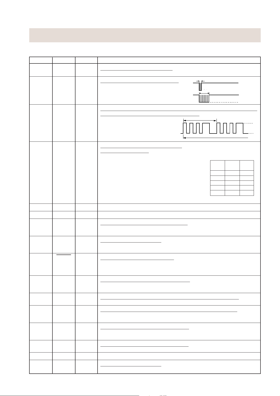
CUISSON A 560 W, 400 W, 240 W, 80 W
Lorsque le four à micro-ondes est réglé à une puissance
de cuisson variable, la tension de ligne est appliquée au
transformateur haute tension de façon intermittente sur
base d’une durée de 27 secondes via le contact de relais,
lequel est couplé au relais
niveaux de puissance des micro-ondes suivants sont
donnés.
REGLAGES;
27 sec. ON
27 sec. ON
800 W
800W
21 sec. ON
21 sec. ON 6 sec. OFF
560 W
560W
15 sec. ON
80W
15 sec. ON
9 sec. ON
9 sec. ON
5 sec. ON
5 sec. ON
400 W
400W
240 W
240W
80 W
REMARQUE: Le rapport de temps de MARCHE/ARRET
(ON/OFF) ne correspond pas exactement
aupourcentage de la puissance des microondes, parce qu’
cessaires pour chauffer le filament du magnétron.
5
RY2 limitateur de courant. Les
6 sec. OFF
Env. 70 %
Approx. 70%
12 sec. OFF
12 sec. OFF
18 sec. OFF
18 sec. OFF
22 sec. OFF
22 sec. OFF
Env. 50 %
Approx. 50%
Env. 30 %
Approx. 30%
Env. 10 %
Approx. 10%
env. 3 secondes sont né-
100%
Page 8
FONCTIONS DES COMPOSANTS IMPORTANTS
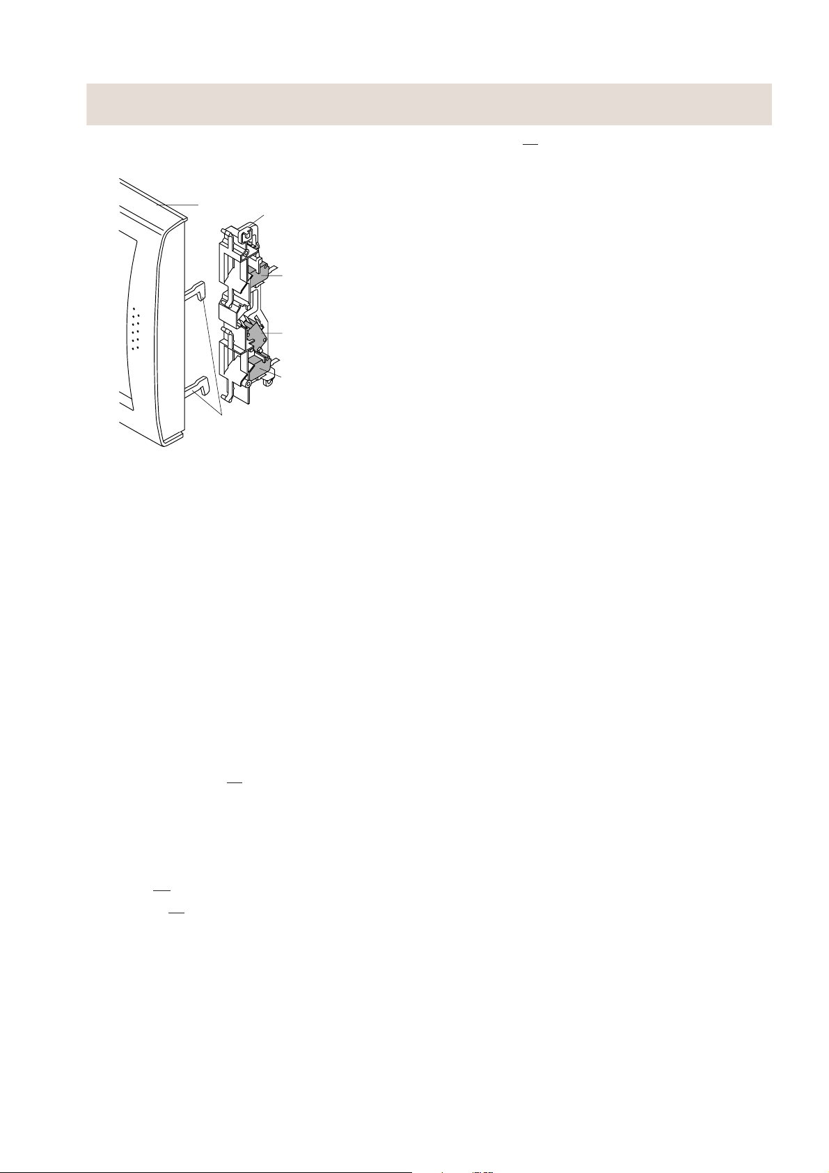
MECANISME D’OUVERTURE DE PORTE
La porte peut être ouverte en tirant sur celle-ci.
PORTE
Door
Latch heads
TETE DE LOQUET
Latch hook
CROCHET DE LOQUET
COMMUTATEUR
SW3: Stop switch
D’ARRET (SW3)
COMMUTATEUR
SW2: Monitor switch
DE CONTROLE (SW2)
SW1: Monitored
COMMUTATEUR
DU LOQUET
latch switch
DE CONTROLE (SW1)
Figure D-1. Mécanisme d’ouverture de porte
COMMUTATEUR DU LOQUET DE CONTROLE
(SW1) ET COMMUTATEUR D’ARRET (SW3)
1. Lorsque la porte du four est fermée, les contacts
(COM-NO) doivent être fermés.
COMMUTATEUR DE CONTROLE (SW2)
1. Lorsque la porte du four est fermée, les contacts
(COM - NC) doivent être ouverts.
2. Lorsque la porte du four est ouverte, les contacts
(COM - NC) doivent être fermés.
3. Si la porte du four est ouverte et les contacts (COM-NO)
du commutateur du loquet de contrôle (SW1) ne s’ouvrent
pas, le fusible F1 saute immédiatement après la fermeture
des contacts (COM-NC) du commutateur de contrôle
(SW2).
ATTENTION: AVANT DE REMPLACER LE FUSIBLE
GRILLE
NEMENT CORRECT DU COMMUTATEUR DU LOQUET DE CONTROLE
(SW1) ET DU COMMUTATEUR DE
CONTROLE (SW2). (SE REPORTER AU
CHAPITRE “PROCEDURE DE TEST”.)
F1, VERIFIER LE FONCTION-
2. Le fusible F1 saute aussi lorsque le redresseur H.T.,
le faisceau de câbles H.T., le condensateur, le magnétron ou l’enroulement secondaire du transformateur
de puissance est court-circuité.
HVT THERMOSTAT 150˚C
Le thermostat protège le transformateur haute tension
contre la surchauffe. Si la température monte au-dessus
de 150˚C parce que le moteur du ventilateur est arrêté ou
les ouvertures de ventilation sont bloquées, le thermostat
est déclenché, et la tension de ligne appliquée au transformateur haute tension est aussi interrompue. (Si le magnétron à fonctionné, contrôler s’il n’est pas endommagé.)
COUPE-CIRCUIT THERMIQUE 125°C (FOUR)
Le coupe-circuit thermique situé au-dessus de la cavité du
four est conçu pour que le four ne soit pas endommagé, si
l’aliment qui se trouve dans le four prend feu à cause d’une
surchauffe survenue suite à un réglage incorrect du temps
de cuisson ou un mauvais fonctionnement de l’unité de
commande. Pendant un fonctionnement normal, le coupecircuit thermique reste fermé. Cependant, lorsque des
températures anormalement élevées sont atteintes à
l’intérieur de la cavité du four, le coupe-circuit thermique
s’ouvre à 125˚C, entraînant l’arrêt du four. Le coupe-circuit
thermique détecteur doit être remplacé par un nouveau.
MOTEUR DU PLATEAU TOURNANT
Le moteur du plateau tournant entraîne l’ensemble cylindre
du plateau tournant pour faire tourner le plateau tournant.
MOTEUR DU VENTILATEUR
Le moteur du ventilateur entraîne une lame qui attire l’air
frais de l’extérieur. Cet air frais est dirigé à travers les
moulinets d’air qui entourent le magnétron et refroidit le
magnétron. Cet air est envoyé à travers la cavité du four
pour éliminer la condensation et les vapeurs dégagées
par les aliments chauffés. Il est ensuite évacué à travers
les bouches d’aération à l’arrière de la cavité du four.
FILTRE ANTIPARASITE
Le filtre antiparasite empêche les interférences de fréquence radio qui pourraient être refoulées dans le circuit
électrique.
FUSIBLE F1
1. Le fusible F1 saute lorsque les contacts (COM-NO)
du commutateur du loquet de contrôle (SW1) restent
fermés lorsque la porte du four est ouverte et lorsque
les contacts (COM-NC) du commutateur de contrôle
(SW2) se ferment.
6
Page 9
GUIDE DE DEPISTAGE DES PANNES
Lors du dépistage des pannes du four à micro-ondes, il est
utile de suivre l’ordre des opérations en effectuant les
vérifications. La plupart des causes possibles des pannes
nécessitent la réalisation d’un test spécifique. Ces tests
sont dotés d’une lettre de procédure qui est reprise dans
la section “Procédure de test”.
PROCEDURE DE TEST
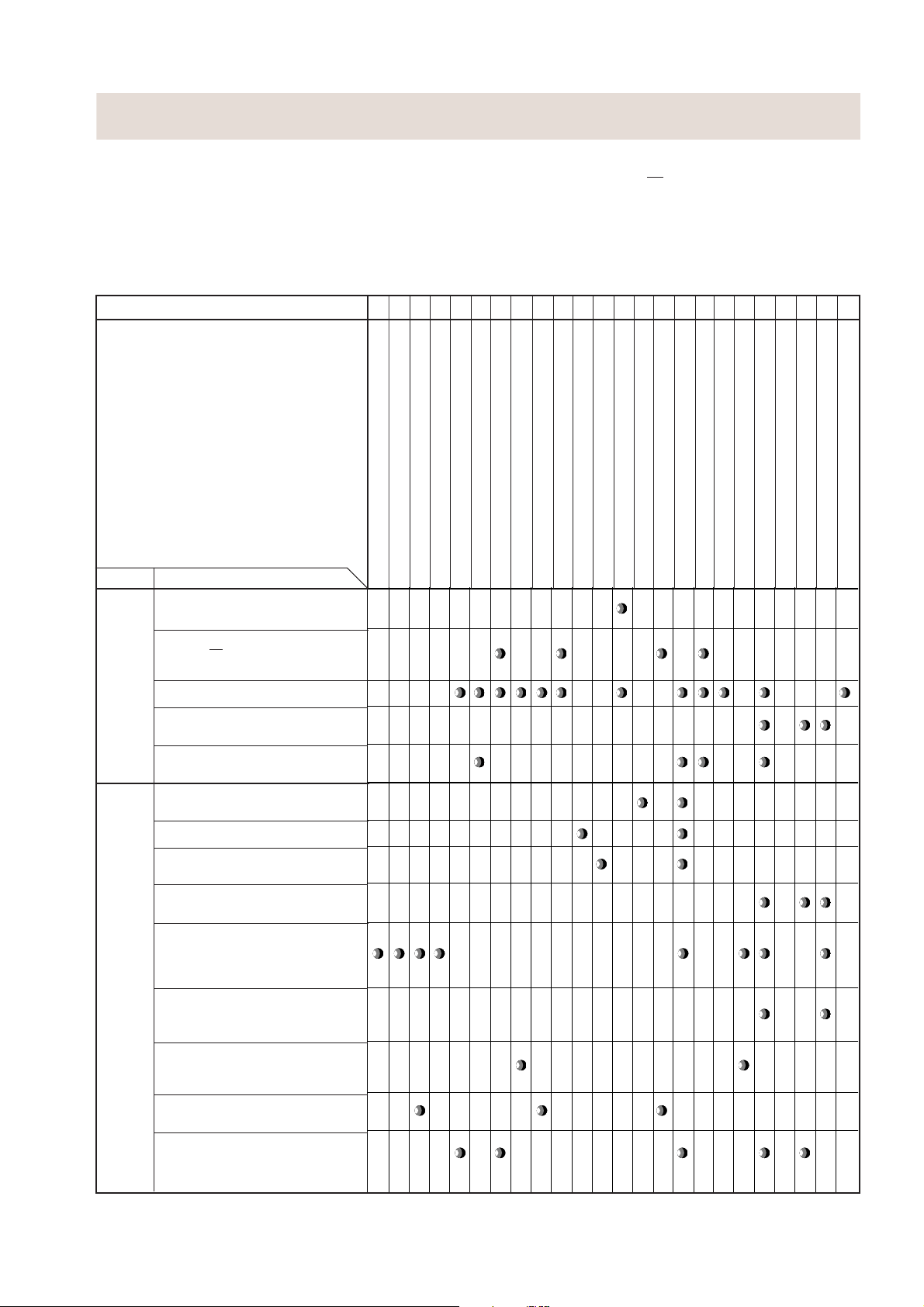
ABCDEEEFGHI I JKLLM
CAUSE INDIRECTE
ET
PIECES DEFECTUEUSES
MODE
MODE
OFF
Le fusible initial saute lorsque le cordon
d’alimentation est branché dans la prise
murale.
Le fusible
mentation est branché dans la prise murale.
(Minuterie arrêtée)
Le four ne fonctionne pas du tout.
Le panneau de commande ne fonctionne
pas, mais lorsque la porte est fermée, le
four commence à fonctionner.
Le four ne démarre pas lorsqu’on fait tourner le bouton de la minuterie.
PROBLEME
F1 saute lorsque le cordon d’ali-
MAGNETRON
TRANSFORMATEUR HAUTE TENSION
REDRESSEUR H.T.
CONDENSATEUR HAUTE TENSION
IMPORTANT: Si le four n’est plus opérationnel parce que
le fusible
F1 est grillé, vérifier le commutateur
du loquet de contrôle et le commutateur de
contrôle avant de remplacer.
COMMUTATEUR DU LOQUET DE CONTROLE
COMMUTATEUR D’ARRET
COMMUTATEUR DE CONTROLE
COUPE CIRCUIT THERMIQUE 125˚C
FUSIBLE F1
FILTRE ANTIPARASITE
MOTEUR DU VENTILATEUR
MOTEUR DU PLATEAU TOURNANT
PRISE OU LAMPE DU FOUR
CORDON D’ALIMENTATON
FAISCEAU DES CABLES COURT CIRCUITE
FAISCEAU DES CABLES OUVERT
COMMUTATEURS MAL REGLE
PAS DE COURANT A LA PRISE MURALE
THERMOSTAT HAUTE TENSION
UNITE DE COMMANDE
COMMUTATEUR SENSITIF
RELAIS RY1
RELAIS RY2
FILM DE PROTECTION
MODE
DE
CUISSON
La lampe du four n’éclaire pas pendant
le fonctionnement.
Le moteur du ventilateur ne fonctionne pas.
L’ensemble moteur du plateau tournant
ne fonctionne pas.
Le four ou les parties électriques ne s’arrêtent pas lorsque le bouton de la minuterie est sur “0”.
Le four semble fonctionner, mais peu de chaleur ou aucune chaleur n’est produite dans
l’aliment. (La commande de puissance microondes est placée sur la position 800 W.)
Le four ne fonctionne pas correctement
pendant le mode de cuisson variable sauf
en mode de cuisson à 800 W.
Le four passe en cycle de cuisson, mais
se coupe avant la fin du cycle de cuisson.
Le four s’arrête dès que le four est mis en
marche.
Le moteur du ventilateur, la lampe du four
et le moteur du plateau tournant ne fonctionnent pas en même temps.
7
Page 10

PROCEDURES DE TEST
LETTRE
DE PROCEDURE
A
TEST DU COMPOSANT
TEST DU MAGNETRON
NE JAMAIS TOUCHER LES PIECES DANS LE CIRCUIT A LA MAIN OU AVEC UN OUTIL ISOLE
PENDANT LE FONCTIONNEMENT DU FOUR.
EFFECTUER LES VERIFICATIONS 3D.
Isoler le magnétron du circuit haute tension en enlevant tous les fils connectés à la borne du filament.
Pour tester si un filament a un circuit ouvert, utiliser un ohmmètre pour faire un test de continuité entre
les bornes de filament du magnétron, l’ohmmètre doit indiquer une valeur inférieure à 1 ohm.
Pour tester un court-circuit du filament en condition d’anode, connecter l’ohmmètre entre une des
bornes de filament et le boîtier du magnétron (masse). Ce test doit indiquer une résistance infinie.
Si une valeur de résistance faible ou nulle est lue, le magnétron doit alors être remplacé.
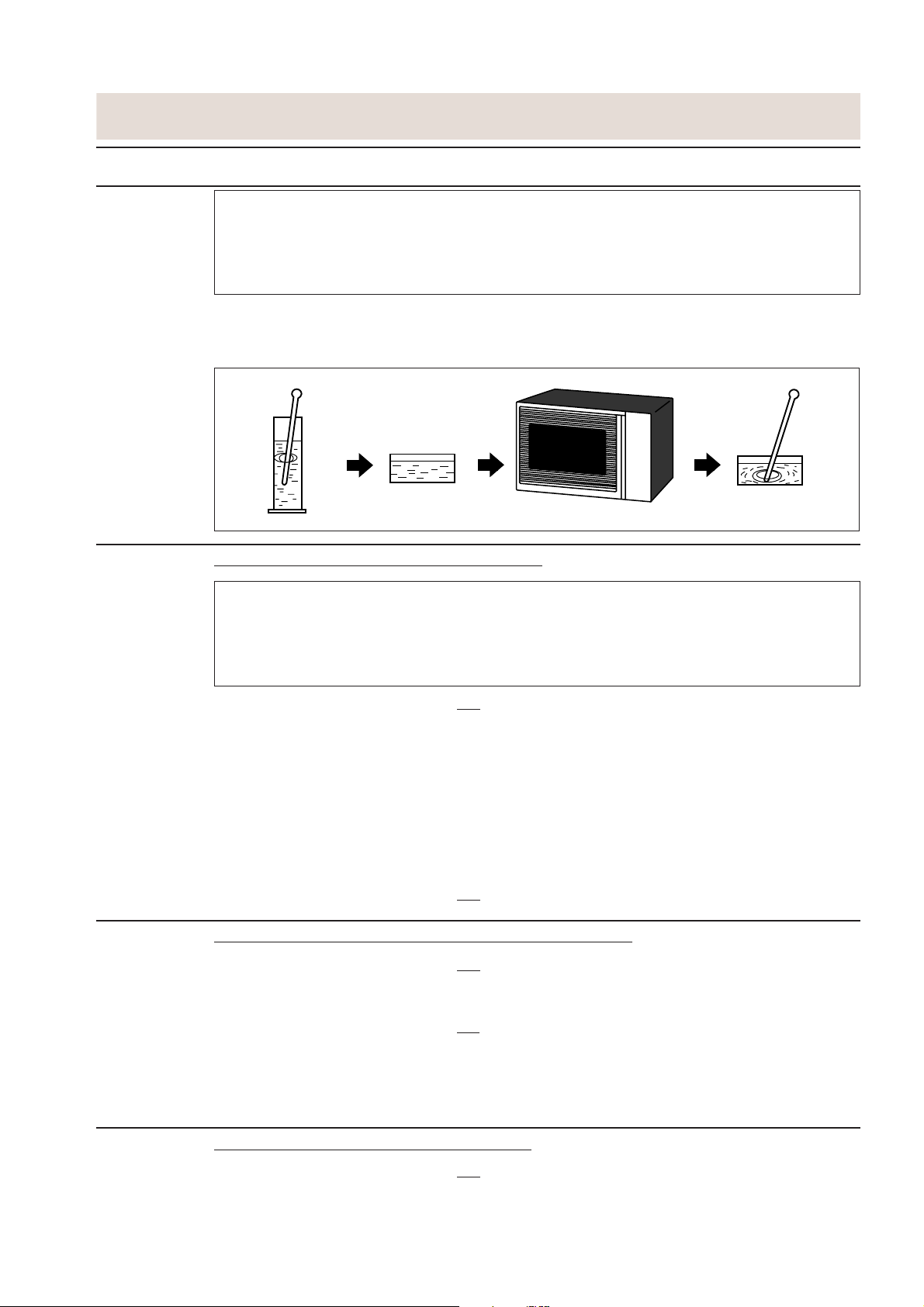
MICROWAVE OUTPUT POWER (IEC-705-1988)
La procédure de test suivante doit être effectuée avec le four à micro-ondes entièrement monté (avec
le boîtier extérieur fixé). La puissance de sortie des micro-ondes provenant du magnétron peut être
mesurée selon la norme IEC 705, c’est-à-dire qu’elle peut être mesurée en utilisant une charge d’eau
et en déterminant quel volume peut être absorbé par la charge d’eau. Pour mesurer la puissance
absorbée des micro-ondes dans le four à micro-ondes, le rapport entre les calories et les Watts est
utilisé. Lorsque le chauffage P(W) fonctionne pendant t (secondes), environ P x t/4,187 calories sont
produites. D’autre part, si la température de l’eau d’un volume de V(ml) monte de ∆T (°C) pendant cette
période de chauffe des micro-ondes, les calories de l’eau sont égales à V x ∆T.
La formule est la suivante;
P x t / 4,187 = V x ∆T P (W) = 4,187 x V x ∆T / t
Les conditions pour la charge d’eau sont les suivantes:
Température ambiante ..environ 20°C Tension d’alimentation.........Tension nominale
Charge d’eau ............................ 1000 g Température initiale...........................10 ± 2°C
Durée de chauffage................52 +3=55 sec.
P = 80 x ∆T
Condition de mesure:
1. Récipient
Le récipient d’eau doit être cylindrique en verre de borosilicate d’une épaisseur maximale de 3 mm
et un diamètre extérieur de 190 mm environ.
2. Température du four et du récipient
Le four et le récipient vide sont à température ambiante avant le démarrage de l’essai.
3. Température de l’eau
La température initiale de l’eau est de (10 ± 2)°C.
4. Sélectionner la température initiale et finale de l’eau de sorte que la différence maximale entre
la température finale de l’eau et la température ambiante soit de 5 K.
5. Sélectionner des agitateurs et instruments de mesure afin de minimiser l’augmentation ou la diminution de chaleur.
6. Le thermomètre doit avoir une graduation de 0,1°C minimum et doit être un thermomètre de précision.
7. La charge d’eau doit être de (1000 ± 5) g.
8. “t” est mesuré pendant que le générateur des micro-ondes fonctionne à pleine puissance. La durée
d’échauffement du filament du magnétron n’est pas incluse.
REMARQUE: La durée de fonctionnement du four à micro-ondes est “t + 3” sec. 3 sec. est la durée
d’échauffement du filament du magnétron.
Méthode de mesure:
1. Mesurer la température initiale de l’eau avant l’ajout d’eau dans le récipient.
(Exemple: La température initiale est T1 = 11°C)
2. Ajouter 1 litre d’eau au récipient.
3. Placer la charge au centre du plateau tournant.
4. Mettre en marche le four à micro-ondes à 800 W pour t + 3 secondes.
5. Immédiatement enlever le récipient et le placer sur une surface isolée.
6. Agiter l’eau pour homogénéiser la température dans tout le récipient.
7. Mesurer la température finale de l’eau. (Exemple: La température finale est T2 = 21°C)
8. Calculer la puissance de sortie des micro-ondes
8
P en Watts à l’aide de la formule ci-dessus.
Page 11
PROCEDURES DE TEST
LETTRE
DE PROCEDURE
B TEST DU TRANSFORMATEUR DE PUISSANCE
TEST DU COMPOSANT
Température initiale ...................................................................................................... T1 = 11°C
Température après (52 + 3) = 55 sec. .......................................................................... T2 = 21°C
Différence de température chaud-froid ......................................................................... ∆T = 10°C
Puissance mesurée
L’équation est “P = 80 x ∆T”.................................................................P = 80 x 10°C = 800 Watts
EVALUATION: La puissance mesurée doit être au moins de
ATTENTION: 1°C CORRESPOND A 80 WATTS. REPETER LA MESURE SI LA PUISSANCE EST
INSUFFISANTE.
1000g
1000g
T1˚C
Chauffe pendant 55 sec.
± 15 % de la puissance de sortie nominale.
1000g
T2˚C
AVERTISSEMENT: Des hautes tensions et courants intensifs sont présents dans l’enrou-
lement secondaire et l’enroulement du filament du transformateur
haute tension. Il est très dangereux de travailler près de cette pièce lorsque le four est en marche. NE JAMAIS effectuer des mesures de tension
des circuits haute tension, y compris du filament du magnétron.
EFFECTUER LES VERIFICATIONS 3D.
Débrancher les fils de l’enroulement primaire du transformateur de puissance. Débrancher les
connexions de l’enroulement du filament et de l’enroulement secondaire du reste des circuits H.T. A
l’aide d’un ohmmètre, réglé sur la valeur minimale, il est possible de vérifier la continuité des trois
enroulements. Les valeurs suivantes doivent être obtenues:
a. Enroulement primaire ............................2,4 ohms environ
b. Enroulement secondaire....................... 140 ohms environ
c. Enroulement du filament.........................inférieur à 1 ohm
Si les indications obtenues ne correspondent pas à celles mentionnées ci-dessus, alors le transformateur
haute tension est probablement défectueux et doit être remplacé.
EFFECTUER LES VERIFICATIONS
4R.
C TEST DE L’ENSEMBLE DE REDRESSEUR HAUTE TENSION
EFFECTUER LES VERIFICATIONS
3D.
Si les valeurs obtenues ne correspondent pas aux valeurs ci-dessus, le transformateur haute tension
est probablement défectueux et doit être remplacé.
EFFECTUER LES VERIFICATIONS
4R.
REMARQUE: POUR LA MESURE DE LA RESISTANCE DU REDRESSEUR, LES PILES DE L’AP-
PAREIL DE MESURE DOIVENT AVOIR UNE TENSION D’AU MOINS 6 VOLTS,
SINON UNE RESISTANCE INFINIE RISQUE D’ETRE INDIQUEE DANS LES DEUX
DIRECTIONS.
D TEST DU CONDENSATEUR HAUTE TENSION
EFFECTUER LES VERIFICATIONS
3D.
A. Isoler le condensateur haute tension du circuit.
B. La vérification de la continuité doit être effectuée à l’aide d’un appareil de mesure réglé sur la valeur
la plus élevée de la résistance.
9
Page 12
PROCEDURES DE TEST
LETTRE
DE PROCEDURE
E TEST DE COMMUTATEUR
TEST DU COMPOSANT
C. Un condensateur normal indique une continuité pendant une courte période (lancement) et ensuite
une résistance de 10 MΩ environ est affichée après son chargement.
D. Un condensateur court-circuité indique une continuité permanente.
E. Un condensateur ouvert indique constamment une résistance de 10 MΩ environ à cause de sa
résistance interne de 10 MΩ.
F. Lorsque le fil interne est ouvert dans le condensateur haute tension, le condensateur indique une
résistance infinie.
G. La résistance à toutes les bornes et au châssis doit être infinie lorsque le condensateur est normal.
Si des valeurs incorrectes sont lues, le condensateur haute tension doit être remplacé.
EFFECTUER LES VERIFICATIONS
4R.
EFFECTUER LES VERIFICATIONS 3D.
Isoler le commutateur à tester et à l’aide d’un ohmmètre, vérifier entre les bornes comme indiqué sur
le tableau suivant.
Tableau: Connexion de borne du commutateur
Fonctionnement de la sonde COM sur NO COM sur NC
Libéré Circuit ouvert Court-circuit
Enfoncé Court-circuit Circuit ouvert
COM; Borne de phase
NO; Normalement une borne ouverte
NC; Normalement une borne fermée
Si des valeurs incorrectes sont obtenues, faire le réglage nécessaire du commutateur ou remplacer
le commutateur.
EFFECTUER LES VERIFICATIONS
4R.
F TEST DE COUPE-CIRCUIT THERMIQUE
EFFECTUER LES VERIFICATIONS
3D.
Débrancher les conducteurs des bornes du coupe-circuit thermique. Ensuite, faire un test de continuité
à travers les deux bornes en utilisant un ohmmètre comme décrit ci-dessous.
EFFECTUER LES VERIFICATIONS
Température en mode “ON” (circuit fermé).............................................................................. Ne peut pas être remise à zéro
Température en mode “OFF” (circuit ouvert) ............................................................................................ Supérieure à 125˚C
Indication de l’ohmmètre (Lorsque la température ambiante est de 20˚C environ.) ............................................. Circuit fermé
4R.
Si des lectures incorrectes sont obtenues, remplacer le coupe-circuit thermique du four.
Un coupe-circuit thermique ouvert (FOUR) indique que les aliments dans le four risquent de brûler, cela
peut être provoqué par une surchauffe produite par un réglage incorrect de la minuterie de cuisson ou
une défaillance du panneau de commande.
G TENSION DU FUSIBLE F1
EFFECTUER LES VERIFICATIONS 3D.
1. Si le fusible
F1 a sauté, il peut y avoir des court-circuits ou des problèmes de masse dans les composants électriques ou dans le faisceau de câbles. Vérifier et remplacer les pièces défectueuses
ou réparer le faisceau de câbles.
2. Si le fusible
F1 est grillé lorsque la porte est ouverte, vérifier le commutateur du loquet de contrôle
et le commutateur de contrôle.
Si le fusible
tateur(s) défectueux et le fusible
F1 a sauté à cause d’une mauvaise commutation de la porte, remplacer le(s) commu-
F1.
EFFECTUER LES VERIFICATIONS
ATTENTION: Ne remplacer le fusible spécial F1 que par un fusible d’une valeur appropriée.
4R.
10
Page 13
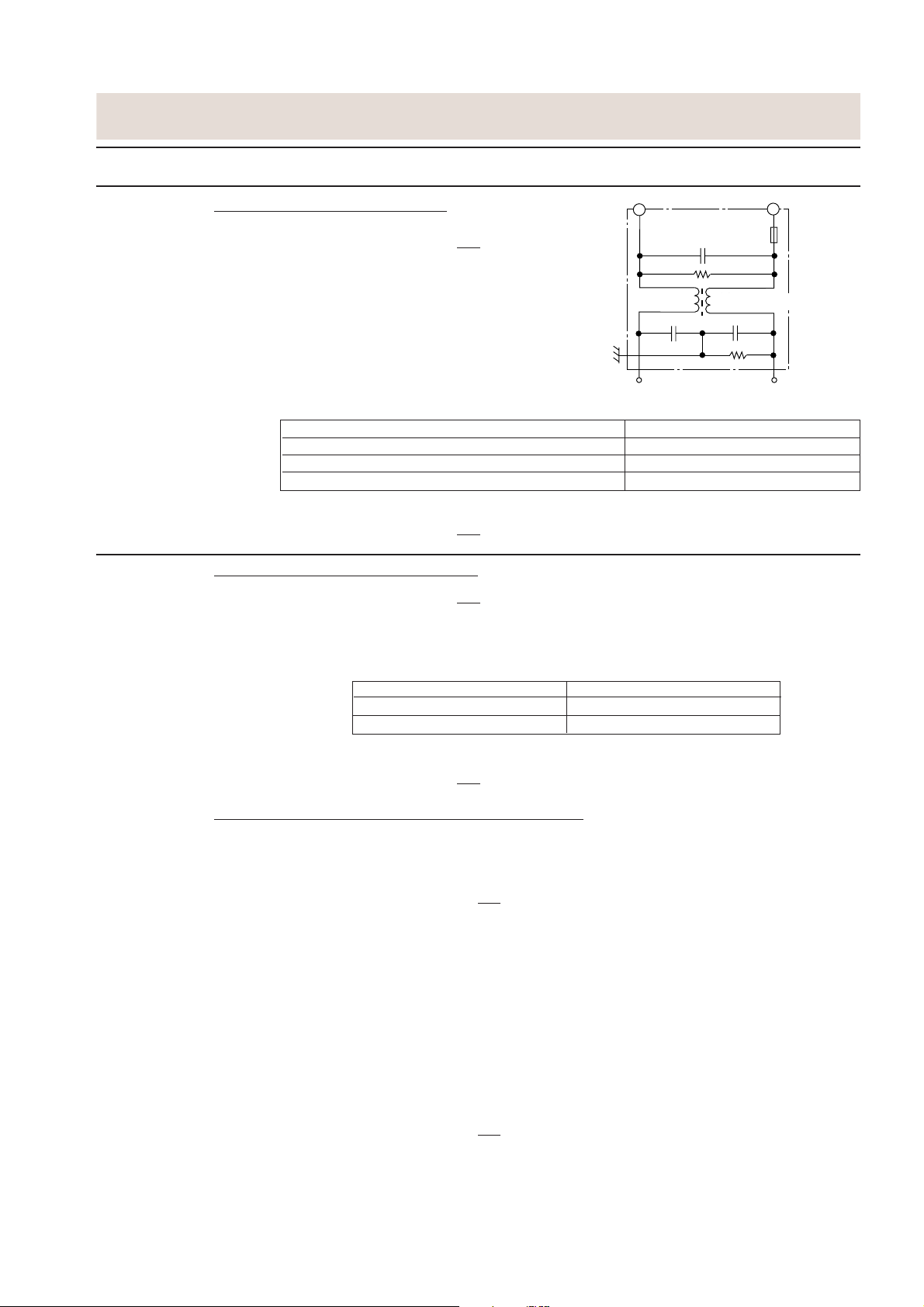
F: FUSE
F1
N
L
0.22µ/AC250V
680K/ 0.5W
10M/ 0.5W
NOISE
SUPPRESSION COIL
0.0033µ/ 250V
0.0033µ/ 250V
NOISE FILTER
RED
WHT
PROCEDURES DE TEST
LETTRE
DE PROCEDURE
H TEST DU FILTRE ANTIPARASITE
I TEST D’ENROULEMENT DE MOTEUR
TEST DU COMPOSANT
EFFECTUER LES VERIFICATIONS
FILTRE ANTI-PARASITE
3D.
F1: FUSIBLE
(F1)
Débrancher les fils des bornes du filtre antiparasite.
A l’aide d’un ohmmètre, vérifier entre les bornes comme
décrit dans le tableau suivant.
BOBINE DE SUPPRE-
SSION DES PARASITES
POINTS DE MESURE INDICATION DE L’OHMMETRE
Entre N et L Env. 680 kΩ
Entre la borne N et BLANCHE Court-circuit
Entre la borne L et ROUGE Court-circuit
Si des valeurs incorrectes sont lues, remplacer l’unité du filtre antiparasite.
EFFECTUER LES VERIFICATIONS
4R.
EFFECTUER LES VERIFICATIONS 3D.
Débrancher les conducteurs du moteur. Utiliser l’ohmmètre pour vérifier la résistance entre les deux
bornes comme décrit sur le tableau ci-dessous.
Tableau: Resistance du moteur
Moteurs Résistance
Moteur de ventilateur Environ 360 Ω
Moteur du plateau tournant Environ 12 - 15 kΩ
Si des lectures incorrectes sont obtenues, remplacer le moteur.
EFFECTUER LES VERIFICATIONS
4R.
TEST EFFECTIF DES ENROULEMENTS DU MOTEUR
ATTENTION: La procédure suivante nécessite la connexion du four à l’alimentation et doit être
utilisée seulement si les vérifications correspondant au test à “froid” du moteur
testé sont concluantes.
1. EFFECTUER LES VERIFICATIONS
3D.
2. Débrancher les fils de l’enroulement primaire du transformateur de puissance. S’assurer que les fils
restent isolés des autres composants du four et du châssis. (Utiliser un ruban isolant si nécessaire.)
3. Connecter un voltmètre, réglé à 250 V CA, aux bornes du moteur. (Se reporter à la procédure de
test du moteur correspondant ou au schéma de principe pour les numéros de borne corrects.)
4. Disposer le voltmètre dans une position où la lecture peut être effectuée pendant le test.
(Ne pas toucher le voltmètre, les fils du voltmètre ou les circuits du four pendant que le four est en
fonctionnement.)
5. Fermer la porte du four.
6. Régler le niveau de puissance sur 800 W et régler la minuterie appropriée à environ trois (3)
minutes.
7. Noter la valeur lue sur le voltmètre et observer avec attention le moteur pendant le test pour voir
s’il tourne.
8. EFFECTUER LES VERIFICATIONS
3D.
9. Retirer les fils de l’appareil de test.
10.Raccorder les fils à l’enroulement primaire du transformateur de puissance.
Si une valeur de la tension de ligne est lue (étape 7), mais le moteur ne tournait pas, il est alors défectueux et doit être remplacé. Si le voltmètre indique qu’aucune alimentation n’était présente, le câblage
du moteur doit être vérifié pour sa continuité.
11
Page 14

PROCEDURES DE TEST
LETTRE
DE PROCEDURE
J TEST DE L’ENSEMBLE DE PANNEAU DE COMMANDE
TEST DU COMPOSANT
Le panneau de commande contient des circuits à semi-conducteurs de type LSI, CI, etc. Par
conséquent, contrairement aux fours à micro-ondes conventionnels, un entretien correct ne peut pas
être effectué avec seulement un voltmètre et un ohmmètre.
Dans ce manuel technique, le dépistage des pannes et le remplacement sont décrits suivant les
symptômes indiqués.
1. Panneau de commande
Les symptômes suivants indiquent une unité de commande défectueuse.
1-1. En relation avec les voyants DEL
a) Sur un certain voyant DEL, tous les voyants DEL ou certains d’entre eux ne s’allument pas.
b) Sur un certain voyant DEL, la luminosité est faible.
c) Seul un voyant DEL ne s’allume pas.
d) Tous les voyants DEL ou certains continuent d’éclairer.
e) Un certain groupe de voyants DEL ne s’allume pas.
f) Les voyants DEL clignotent.
1-3. Commutateur sensitif
a) Lorsqu’une touche sensitive est effleurée, une touche sensitive ne produit aucun signal.
b) La cuisson n’est pas possible.
c) Le temps de cuisson ne peut pas être réglé.
d) Le niveau de puissance ne peut pas être réglé.
K TEST DU COMMUTATEUR SENSITIF
1. EFFECTUER LES VERIFICATIONS
2. Déposer l’unité de commande du panneau de commande.
3. A l’aide d’un ohm-mètre, vérifier le fonctionnement du commutateur sensitif.
4. Lorsque le commutateur sensitif n’est pas enfoncé, l’ohm-mètre doit indiquer un circuit ouvert.
Lorsque le commutateur sensitif n’est pas enfoncé, l’ohm-mètre doit indiquer un court-circuit. Si
un mauvais fonctionnement est indiqué, le commutateur sensitif est probablement défectueux et
doit être contrôlé.
5. EFFECTUER LES VERIFICATIONS
L TEST DU RELAIS
EFFECTUER LES VERIFICATIONS 3D.
Déposer le coffret extérieur et vérifier la tension entre les broches No. 3 et 5 du connecteur à 3 broches
(A) de l’unité de commande à l’aide d’un voltmètre CA.
Le voltmètre doit indiquer 230 Volts, sinon vérifier le circuit du four.
Test de relais
Vérifier la tension à la bobine du relais à l’aide d’un voltmètre CC pendant la cuisson aux micro-ondes.
Tension CC indiquée .......... Relais défectueux.
Tension CC non indiquée ... Vérifier la diode qui est connectée à la bobine du relais. Si la diode
est correcte, l’unité de commande est défectueuse.
3D.
4R après le test.
SYMBOLE DE RELAIS TENSION DE SERVICE COMPOSANTS CONNECTES
RY1 Env. 12,0 V CC Lampe du four / moteur du plateau
RY2 Env. 11,0 V CC Transformateur haute tension
tournant / Moteur du ventilateu
EFFECTUER LES VERIFICATIONS 4R.
12
Page 15
PROCEDURES DE TEST (SUITE)
LETTRE
DE PROCEDURE
M PROCEDURES A RESPECTER LORSQUE LE FILM DE PROTECTION SUR LA PLAQUETTE
TEST DU COMPOSANT
DE MONTAGE IMPRIMEE (PWB) EST OUVERT
Pour protéger les circuits électroniques, ce modèle est équipé d’un film de protection ajouté au primaire
de la plaquette de montage imprimée (PWB), ce film de protection agit comme un fusible. Si le film de
protection est ouvert, suivre le guide de dépistage des pannes ci-dessous pour effectuer la réparation.
Problème: L’indicateur de mise sous tension (POWER ON) ne s’allume pas.
EFFECTUER LES VERIFICATIONS
ACTIONS
La tension nominale secteur n’est pas Vérifier la tension et le cordon d’alimentation du four.
1
présente à la borne d’alimentation (Power)
du connecteur de la CPU (CN-A).
La tension nominale secteur est présente Le transformateur basse tension ou le circuit du
2
sur l’enroulement primaire du transformateur secondair est défectueux. Vérifier et réparer.
basse tension.
3 Le film est brisé seulement au point “a”.
4 Le film est brisé aux points “a” et “b”.
OCCURRENCE CAUSE OU REMEDE
4R.
*Insérer un fil cavalier J1 et le souder. (EFFECTUER
LES VERIFICATIONS
*Insérer la bobine RCILF2003YAZZ entre “c” et “d”.
(EFFECTUER LES VERIFICATIONS
REPARER)
3D AVANT DE REPARER)
3D AVANT DE
REMARQUE: *Au moment des réparations, faire
une inspection visuelle des dommages provoqués par grillage de la
varistance et examiner dans le trans-
P
VRS1
RY1
formateur la présence de court-circuits entre couches à l’aide du
testeur (vérifier la résistance de l’enroulement primaire).
S’il y a une anomalie, remplacer les
pièces défectueuses.
T1
1
d
ab
(J1)
c
CN - A
15
EFFECTUER LES VERIFICATIONS 4R.
13
Page 16

ENSEMBLE NUMERIQUE-ANALOGIQUE
DESCRIPTION DU PANNEAU DE COMMANDE
Unité de commande
L’unité de commande comprend un circuit LSI, un circuit
de source d’alimentation, un circuit de synchronisation du
signal, un circuit ACL, un circuit de sonnerie, un circuit de
mesure de température et un circuit d’indicateur.
1) LSI
Ce circuit LSI commande le signal de l’encodeur, le
signal d’échantillonnage du commutateur sensitif, le
signal d’entraînement du relais de fonction du four, le
signal de l’alarme et le signal DEL.
2) Circuit de source d’alimentation
Ce circuit produit la tension nécessaire dans l’unité de
commande.
Symbol Voltage Application
VC -5,0 V LSI (I-1)
VR -12,0 V RELAY (RY1,2)
3) Circuit de signal de synchronisation
Le signal de synchronisation de la source d’alimentation
est disponible pour la composition d’une durée standard de base dans le circuit d’horloge. Il comporte une
petite erreur, parce qu’il fonctionne sur une fréquence
commerciale.
4) Circuit ACL
Un circuit pour produire des signaux qui remettent le
circuit LSI à son état initial lorsque l’appareil est mis en
marche.
5) Circuit de sonnerie
La sonnerie répond aux signaux du circuit LSI pour
émettre des sons (son de touche enfoncée et son de fin
de session).
6) Commutateur de détection de porte
(Commutateur d’arrêt)
Un commutateur pour “indiquer” au circuit LSI si la
porte est ouverte ou fermée.
7) Circuit de relais
Pour entraîner le magnétron, le moteur du ventilateur,
le moteur du plateau tournant et pour allumer la lampe
du four.
8) Encodeur
L’encodeur génère le signal pulsationnel, et le signal
pulsationnel est renvoyé au LSI.
9) Circuit d’indicateur
Les éléments de l’indicateur sont des diodes
électroluminescentes (LD1 à LD24 et LD30 à LD 34).
Ce circuit consiste en 4 chiffres et 8 segments.
10) Commutateur sensitif
Le signal généré dans le circuit LSI est envoyé au
commutateur sensitif. Lorsqu’un commutateur sensitif
est effleuré, un signal est produit via le commutateur
sensitif et retransmis au circuit LSI pour exécuter la
fonction requise.
14
Page 17
20 msec
During cooking
H
L
DESCRIPTION DU CIRCUIT LSI
LSI(IZA948DR)
Le signal E/S du circuit LSI(IZA948DR) est décrit en détail dans le tableau suivant.
Broche No.
Signal E/S Description
1 D3 SORTIE Signal de données des segments.
Le signal est envoyé aux cathodes des diodes électroluminescentes (LD8, LD16 et LD24).
0,12 sec.
2 D4 SORTIE Signal pour faire retentir la sonnerie.
A: Son d’effleurement de touche sensitive.
B: Son de fin de cycle.
0.12 sec
A
B
2,4 sec.
2.4 sec
H: GND
-5 V
L: -5V
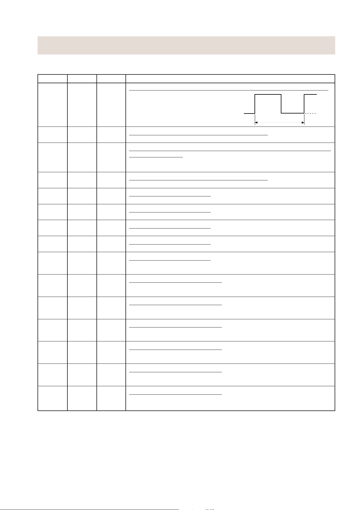
3 D5 SORTIE Signal d’entraînement du moteur de la lampe du four, du plateau tournant
et du ventilateur (forme d’onde carrée : 50 Hz).
Pour activer et désactiver le relais
(RY1). La tension de la forme d’onde
carrée est délivrée au circuit
4 D6 SORTIE
d’entraînement du relais (RY1) et au
circuit de commande du relais (RY2).
Signal d’entraînement du circuit haute
tension du magnétron.
Pour activer et désactiver le relais de
cuisson (RY2). En mode d’alimentation
100%, les signaux maintiennent le niveau
“L” pendant la cuisson aux micro-ondes
et le niveau “H” hors cuisson. Dans
d’autres modes de cuisson (70%, 50%,
30%, 10%), le signal passe au niveau “H”
et au niveau “L” de façon répétitive selon
Pendant la cuisson
Rapport de temps
MARCHE/ARRET en
cuisson micro (base de
temps de 27 secondes)
CUISSON
MICRO
100% 27 sec. 0 sec.
70% 21 sec. 6 sec.
50% 15 sec. 12 sec.
30% 9 sec. 18 sec.
10% 5 sec. 22 sec.
MARCHE
ARRET
le niveau de puissance.
5D7
ENTREE/SORTIE
Borne inutilisée.
6 P20 ENTREE Connecté à la 0V.
7 P21 ENTREE
Signal provenant d’une touche sensitive.
Lorsqu’une touche sensitive SW2 est effleurée, un signal est entré dans P21.
Lorsqu’aucune touche sensitive n’est effleurée, le signal est maintenu au niveau “H”.
8 P22 ENTREE
Signal venant de l’encodeur.
Lorsque l’encodeur est activé, les contacts de l’encodeur produisent des signaux
d’impulsions. Et les signaux d’impulsion sont entrés dans P22.
9 RESET ENTREE
Borne d’initialisation automatique.
Un signal est entré pour remettre le circuit LSI dans son état initial à la mise sous
tension. Temporairement mis au niveau “L” au moment de la mise sous tension,
le circuit LSI est initialisé à ce moment. Ensuite, il est remis au niveau “H”.
10 CNVSS ENTREE
Borne d’entrée de la tension de référence.
Une tension de référence est appliquée au convertisseur A/N dans le circuit LSI.
Connecté à VC.
11 XOUT SORTIE
Sortie de commande fréquence d’oscillation de l’horloge interne.
Sortie pour contrôler l’entrée d’oscillation de XOUT.
12 XIN ENTREE
Réglage d’entrée de fréquence d’oscillation de l’horloge interne.
La fréquence de l’horloge interne est réglée en insérant le circuit d’oscillation du
filtre céramique par rapport à la borne XIN.
13 VSS ENTREE
Tension de la source d’alimentation: -5 V.
La tension de la source d’alimentation de l’entraînement du circuit LSI est entrée
dans la borne VSS. Connecté à VC.
14 VDD ENTREE
Tension de la source d’alimentation : 0 V.
La tension de la source d’alimentation d’entraînement du circuit LSI est entrée à la borne VDD.
15 N.F ENTREE Connecté à la borne VSS.
16 INT0 ENTREE
Signal venant de l’encodeur.
Signal similaire à INT0. Des signaux d’impulsions sont entrés dans INT0.
15
Page 18
DESCRIPTION DU CIRCUIT LSI
LSI(IZA948DR)
Le signal E/S du circuit LSI(IZA948DR) est décrit en détail dans le tableau suivant.
Broche No.
17 INT1 ENTREE Signal synchronisé LSI avec la fréquence de la source commerciale (50 Hz).
18-19 AIN0-AIN1 ENTREE Borne pour changer les fonctions selon le modèle.
20 AIN2 ENTREE
21 AIN3 ENTREE
22 P00 SORTIE
23 P01 SORTIE
24 P02 SORTIE
25 P03 SORTIE
26 P10 SORTIE
27 P11 SORTIE
28 P12 SORTIE
29 P13 SORTIE
30 D0 SORTIE
31 D1 SORTIE
32 D2 SORTIE
Signal E/S Description
C’est la synchronisation de base pour le
traitement de temps réel du circuit LSI.
20 msec
Un signal selon le modèle utilisé est appliqué pour établir cette fonction.
Signal d’entrée qui communique l’information d’ouverture/fermeture de la
porte au circuit LSI.
Porte fermée : signal de niveau “H”.
Porte ouverte : signal de niveau “L”.
Borne pour changer les fonctions selon le modèle.
Un signal selon le modèle utilisé est appliqué pour établir cette fonction.
Signal de sélection de chiffre.
Un signal est envoyé aux anode des diodes électroluminescentes (LD30 à LD34).
Signal de sélection de chiffre.
Un signal est envoyé aux anode des diodes électroluminescentes (LD9 à LD16).
Signal de sélection de chiffre.
Un signal est envoyé aux anode des diodes électroluminescentes (LD17 à LD24).
Signal de sélection de chiffre.
Un signal est envoyé aux anode des diodes électroluminescentes (LD1 à LD8).
Signal de sélection de chiffre.
Un signal est envoyé aux anode des diodes électroluminescentes (LD1, LD9,
LD17 et LD30).
Signal de données des segments.
Un signal est envoyé aux anode des diodes électroluminescentes (LD2, LD10,
LD18 et LD31).
Signal de données des segments.
Un signal est envoyé aux anode des diodes électroluminescentes (LD3, LD11,
LD19 et LD32).
Signal de données des segments.
Un signal est envoyé aux anode des diodes électroluminescentes (LD4, LD12 et
LD20).
Signal de données des segments.
Un signal est envoyé aux anode des diodes électroluminescentes (LD5, LD13,
LD21 et LD33).
Signal de données des segments.
Un signal est envoyé aux anode des diodes électroluminescentes (LD6, LD4,
LD22 et LD34).
Signal de données des segments.
Un signal est envoyé aux anode des diodes électroluminescentes (LD7, LD15 et
LD23).
H : GND
L (-5V)
(-5 V)
16
Page 19
REPARATION
1. Précautions de manipulation des composants
électroniques
Cette unité utilise des circuits CMOS LSI dans la partie
intégrale des circuits. Lors de la manipulation de ces
pièces, les précautions suivantes doivent être
rigoureusement respectées. Les circuits CMOS LSI
ont une très haute impédance aux bornes d’entrée et
de sortie. Pour cette raison, ils sont facilement affectés
par la source d’alimentation haute tension environnante,
l’électricité statique dans les vêtements, etc. et parfois
ils ne sont pas complètement protégés par le circuit de
protection incorporé.
Afin de protéger le circuit CMOS LSI.
1) Lors du stockage et du transport, bien l’envelopper
dans une feuille d’aluminium. Envelopper
également les plaquettes de montage imprimée
(PWB) dans une feuille d’aluminium.
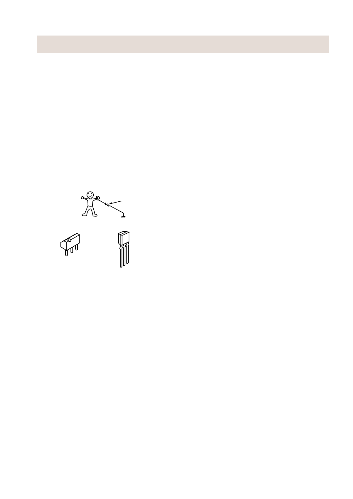
2) Lors du soudage, mettre le technicien à la masse
comme indiqué sur la figure et utiliser un fer à
souder et un plan de travail mis à la masse.
env. 1 Mohm
approx. 1M ohm
2. Formes des composants électroniques
C
B
Transistor
DTA123ES
DTA143ES
DTB123ES
DTD143ES
B
C
E
Transistor
2SB1238
E
3. Réparation du panneau de touches de commande
Les procédures permettant de réparer le panneau de
touches de commande du four à micro-ondes sont
décrites ainsi que les précautions à prendre.
Pour effectuer les réparations, l’alimentation du
panneau de commande des touches est disponible
soit de la ligne d’alimentation du four, soit de la source
d’alimentation externe.
(1) Réparation du panneau de commande des
touches avec l’alimentation du four:
ATTENTION:
LE TRANSFORMATEUR HAUTE TENSION DU
FOUR A MICRO-ONDES EST ENCORE ACTIF
PENDANT LA REPARATION ET PRESENTE
UN DANGER.
Par conséquent, lors de la vérification de la performance du panneau de commande des touches,
placer le boîtier extérieur sur le four pour éviter de
toucher le transformateur haute tension, ou débrancher la borne de l’enroulement primaire (connecteur)
du transformateur haute tension pour le désactiver;
le bout d’un tel connecteur doit être isolé par un
ruban isolant. Après la réparation, s’assurer de
remettre les fils sur leurs emplacements originaux.
A. Sur certains modèles, le cordon d’alimentation
entre le panneau de commande des touches et
le four est si court que les deux ne peuvent pas
être séparés.
Pour ces modèles, vérifier et réparer toutes les
commandes (y compris celles liées au détecteur)
du panneau de commande des touches tout en
les maintenant connectés au four.
B. Sur certains modèles, le cordon d’alimentation
entre le tableau de commande des touches et le
four est tellement assez long que les deux peuvent
être séparés. Pour ces modèles, il est possible de
vérifier et de réparer les commandes du tableau de
commande des touches tout en le séparant du
four; dans ce cas il faut court-circuiter les bouts du
commutateur de détection de porte (sur la plaquette
de circuit imprimé) du tableau de commande des
touches à l’aide d’un cavalier, qui amène un état de
fonctionnement équivalent à celui de la porte du
four fermée. Comme pour les commandes liées à
la détection du tableau de touches de commande,
la vérification est possible si la (les) résistance(s)
fictive(s) d’une résistance égale à celle des
commandes est (sont) utilisée(s).
(2) Réparation du panneau de commande des
touches avec l’alimentation d’une source
d’alimentation externe:
Débrancher complètement le panneau de commande
des touches du four et court-circuiter les deux bouts
du commutateur de détection de porte (sur la plaquette
PWB) du panneau de commande des touches, qui
amène un état de fonctionnement équivalent à celui
de la porte fermée. Connecter une source d’alimentation externe à la borne d’entrée d’alimentation
du panneau de commande des touches, ensuite il
est possible de vérifier et réparer les commandes du
panneau de commande des touches, il est aussi
possible de vérifier les commandes liées à la détection
du panneau de commande des touches en utilisant
la (les) résistance(s) fictive(s).
4. Outillage pour la réparation
Outils nécessaires pour réparer l’ensemble panneau
de commande des touches.
1) Fer à souder: 30 W
(Il est recommandé d’utiliser un fer à souder avec
une borne de masse.)
2) Oscilloscope: Monofaisceau, plage de fréquence:
CC - 10 MHz ou modèle plus récent.
3) Autres outils: Outils à main.
5. Autres précautions
1) Avant d’activer la source d’alimentation de l’unité
de commande, enlever la feuille d’aluminium appliquée pour éviter l’électricité statique.
2) Connecter le connecteur de l’unité des touches
à l’unité de commande en s’assurant si les fils du
conducteur ne sont pas torsadés.
Après avoir enlevé la feuille d’aluminium, faire attention
3)
à ne pas appliquer une tension anormale due à l’électricité
statique etc. aux bornes d’entrée ou de sortie.
4) Fixer les connecteurs, les condensateurs électrolytiques, etc. à la plaquette de montage imprimé, en
s’assurant si toutes les connexions sont serrées.
5) S’assurer d’utiliser les composants spécifiés lorsqu’une haute précision est exigée.
17
Page 20

REMPLACEMENT DES COMPOSANTS ET PROCEDURE DE REGLAGE
AVERTISSEMENT: Eviter toute exposition à l’énergie des micro-ondes. Suivre les instructions ci-dessous
avant d’utiliser le four.
1. Débrancher le four de la prise d’alimentation.
2. Verifier visuellement si la porte, le support ou le crochet
est endommagé.
Effectuer tout travail de réparation nécessaire avant
d’utiliser le four.
Ne pas utiliser le four si une des conditions suivantes se
présente;
1. La porte ne ferme pas hermétiquement.
2. La charnière, le support ou le crochet de loquet de la
porte est endommagé.
3. Le joint ou le film de la porte est endommagé.
Prière de se reporter à “PIECES DU FOUR ET DU BOITIER, PIECES DU PANNEAU DE COMMANDE, PIECES DE LA
PORTE” lors des procédures de dépose suivantes:
4. La porte est déformée ou gondolée.
5. Il y a des pièces défectueuses dans le système de
verrouillage de la porte.
6. Il y a des pièces défectueuses dans l’ensemble de
production et de transmission de micro-ondes.
7. Il y a des détériorations visibles du four.
Ne pas utiliser le four:
1. Sans la garniture FR (magnétron).
2. Si le guide d’ondes ou la cavité du four ne sont pas intacts.
3. Si la porte n’est pas fermée.
4. Si le boîtier extérieur (coffret) n’est pas fixé.
AVERTISSEMENT POUR LE CABLAGE
AVERTISSEMENT: CABLAGE/RECABLAGE
Avant d’entreprendre toute opération, faites les
RECABLAGE
Vérifier les points suivants :
1. Les câbles ne doivent pas se toucher:
a) Pièces à haute tension.
(Magnétron, transformateur haute tension, condensateur haute tension et ensemble de redresseur
haute tension)
b) Pièces qui deviennent chaudes.
(Eléments chauffants, lampe du four, magnétron de la cavité du four et transformateur haute tension)
c) Bords tranchants.
(Plaques inférieures, cavité du four, bord de guide d’onde, support du châssis et autres pièc métalliques)
d) Pièces mobiles.
(Pale du ventilateur, tout moteur, commutateur, levier de commutateur et touche d’ouverture)
2. Les connecteurs “Positive lock” sont placés correctement.
3. Les fils sont raccordés correctement selon le diagramme schématique.
4. Aucun fil conducteur n’est coincé par le couvercle extérieur.
vérifications 3D.
1. Débrancher l’ alimentation
2. Ouvrir la porte et la bloquer avec une cale.
3. Décharger le condensateur haute-tension.
DEPOSE DU BOITIER EXTERIEUR
Pour déposer le boîtier extérieur, procéder comme suit.
1. Débrancher l’alimentation du four.
2. Ouvrir la porte du four et la maintenir ouverte avec une
cale.
3. Déposer les vis a l’arrière et le long du bord du coffret.
4. Glisser le boîtier entier en arrière de 3 cm environ pour
le dégager des attaches de retenue sur la plaquette
avant de la cavité.
5. Soulever le boîtier entier du four.
6. Décharger le condensateur H.T. avant d’effectuer
d’autres travaux.
7. Ne pas utiliser le four avec le boîtier extérieur déposé.
REMARQUE: Les étapes 1, 2 et 6 forment la base des
vérifications
ATTENTION: DECHARGER LE CONDENSATEUR
HAUTE TENSION AVANT D TOUCHER
TOUT COMPOSANT DU FOUR OU LE
CABLAGE.
3D.
DEPOSE DE COMPOSANTS HAUTE TENSION
(CONDENSATEUR HAUTE TENSION ET ENSEMBLE DE REDRESSEUR HAUTE TENSION)
Pour la dépose des composants, procéder de la façon
suivante.
1. EFFECTUER LES VERIFICATIONS
2. Débrancher tous les fils et bornes de l’ensemble de
redresseur haute tension du condensateur haute tension.
3. Déposer la vis (1) fixant la borne de masse de l’ensemble
du redresseur haute tension et déposer le support de
condensateur de la plaque de base.
4. Deposer le condensateur du support de condensateur.
3D.
5. Maintenant l’ensemble du redresseur haute tension et
le condensateur doivent être dégagés.
ATTENTION: LORS DE LA MISE EN PLACE DE L’EN-
SEMBLE DU REDRESSEUR HAUTE
TENSION, S’ASSURER SI LA CONNEXION DE LA CATHODE (MASSE) EST
FERMEMENT FIXEE AU SUPPORT DE
CONDENSATEUR A L’AIDE D’UNE VIS
DE MISE A LA MASSE.
18
Page 21

DEPOSE DU TRANSFORMATEUR DE HAUTE TENSION
1. EFFECTUER LES VERIFICATIONS 3D.
2. Débrancher les conducteurs du filament du
transformateur haute tension du condensateur haute
tension et du magnétron.
3. Débrancher le fil H.T. A du condensateur haute tension.
DEPOSE DU MAGNETRON
1. EFFECTUER LES VERIFICATIONS 3D.
2. Débrancher le fil H.T. B et le conducteur du filament du
transformateur du magnétron.
3. Retirer la vis du support de châssis et la vis fixant le
support de châssis au magnétron.
4. Déplacer le conduit d’admission d’air vers la gauche.
5. Déposer délicatement les deux (2) vis fixant le
magnétron au guide d’ondes; en déposant les vis,
maintenir le magnétron pour ne pas qu’il tombe.
6. Déposer avec précaution le magnétron du guide
DEPOSE DE L’ENSEMBLE DU PANNEAU DE COMMANDE
1. EFFECTUER LES VERIFICATIONS
2. Débrancher le faisceau de câbles principal du panneau
de commande.
3. Déposer la (1) vis fixant le panneau de commande à la
cavité du four.
3D.
DEPOSE DU MOTEUR DU PLATEAU TOURNANT
4. Retirer les quatre (4) vis fixant le transformateur à la
plaque de base.
7. Déposer le transformateur.
8. Maintenant, le transformateur haute tension est libre.
d’ondes de sorte que l’antenne de magnétron ne soit
pas cognée par un objet métallique autour de l’antenne.
ATTENTION: LORS DU REMPLACEMENT DU MAG-
NETRON, S’ASSURER SI LA GARNITURE R.F. EST EN PLACE ET SI LES
VIS DU MAGNETRON SONT FERMEMENT SERREES.
REMONTER LE MAGNETRON DE
MANIERE A CE QUE LE BORD DU GUIDE
D’ONDES SOIT POSITIONNE AVEC LES
DEUX (2) VIS
4. Soulever l’ensemble du panneau de commande et le
tirer vers l’avant. Maintenant l’ensemble de panneau
de commande est dégagé.
EN DIAGONALE.
1. Débrancher l’alimentation du four.
2. Déposer le cache du moteur du plateau tournant en
découpant les quatre coins.
3. Là où les coins ont été coupés, aplatir la matière des zones
de coins. Aucun bord saillant ne peut apparaître après la
dépose du couvercle du moteur du plateau tournant.
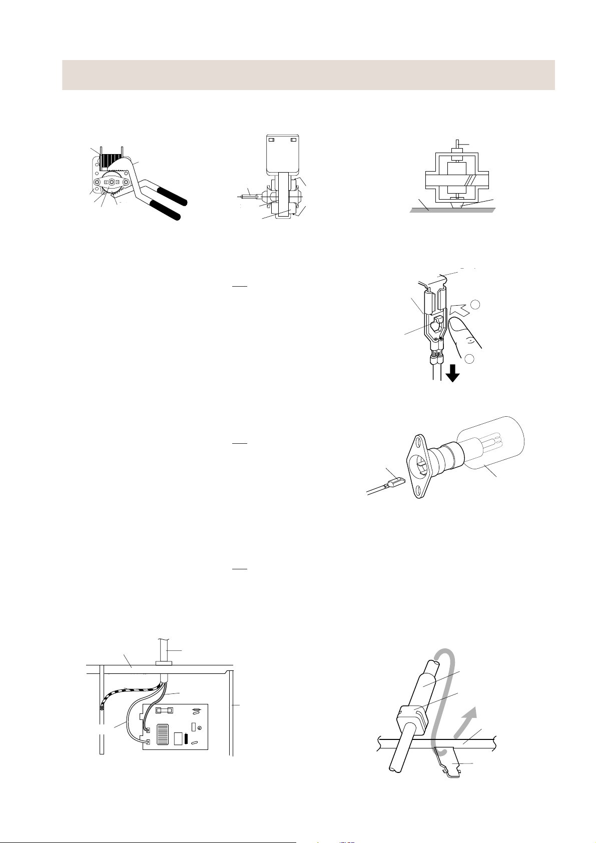
REMPLACEMENT DU MOTEUR DU VENTILATEUR
DEPOSE
1. EFFECTUER LES VERIFICATIONS 3D.
2. Débrancher les fils conducteurs du moteur de ventilateur.
3. Déposer les deux (2) vis fixant le moteur du ventilateur
à la plaque arrière de la cavité du four.
4. Déposer la pale de ventilateur de l’arbre du moteur de
ventilateur selon la procédure suivante.
1) Maintenir le bord du rotor du moteur de ventilateur
à l’aide d’une paire de pinces à étau.
ATTENTION:
• S’assurer que les pièces n’entrent pas dans
l’écartement entre le rotor et le starter du
moteur de ventilateur. Parce que le rotor est
facilement raclé par la pince et des pièces
métalliques risquent d’être produites.
• Ne pas mettre la pince en contact avec la
bobine du moteur de ventilateur, parce que la
bobine risque d’être coupée ou détériorée.
• Ne pas déformer le support en utilisant les pinces.
2) Déposer l’ensemble de pale de ventilateur de l’arbre
du moteur de ventilateur et faire tourner le la pale de
ventilateur à la main.
3) Maintenant, la pale de ventilateur est dégagée.
4. Débrancher le fil conducteur du moteur du plateau
tournant et retirer une (1) vis fixant le moteur du plateau
tournant.
5. Maintenant, le moteur du plateau tournant est dégagé.
6. Après remise en place, utiliser la (1) vis pour fixer le
couvercle du moteur du plateau tournant.
ATTENTION:
• Ne pas réutiliser la pale de ventilateur déposée,
parce que le trou (pour l’arbre) risque de
devenir plus grand qu’un trou standard.
5. Maintenant, le moteur du ventilateur est dégagé.
INSTALLATION
1. Installer la pale de ventilateur sur l’arbre du moteur de
ventilateur selon la procédure suivante.
1) Tenir le centre du support qui supporte l’arbre du
moteur de ventilateur sur une table horizontale.
2) Installer l’ensemble de pale de ventilateur sur l’arbre
de moteur de ventilateur avec un petit marteau à
panne bombée, léger, ou un maillet en caoutchouc.
ATTENTION:
• Ne pas cogner la pale de ventilateur lors de
l’installation, parce que le support risque d’être
transformé.
• S’assurer que la pale de ventilateur tourne
régulièrement après l’installation.
• S’assurer que l’axe de l’arbre n’est pas incliné.
2. Installer le moteur de ventilateur sur la plaque arrière
de la cavité du four à l’aide des deux (2) vis.
19
Page 22
REMPLACEMENT DU MOTEUR DU VENTILATEUR (Suite)
3. Raccorder les fils conducteurs au moteur de ventilateur,
en se rapportant au diagramme schématique.
Bobine
Coil
Pinces à étau
Groove joint pliers
Arbre
Stator
Stator
Ecartement
Gap
Bracket
Support
Rotor
Rotor
Axis
Axe
Shaft
Stator
Stator
Rotor
Rotor
Vue arrière Vue latérale
DEPOSE DU CONNECTEUR A VERROUILLAGE POSITIF (POSITIVE LOCK®)
1. EFFECTUER LES VERIFICATIONS 3D.
2. Pousser sur le levier du connecteur “positive lock
3. Tirer le connecteur “positive lock
ATTENTION: LORSQUE LES CONNECTEURS “POSI-
®
TIVE LOCK
” SONT CONNECTES AUX
BORNES, CONNECTER LE “POSITIVE
®
” DE SORTE QUE LE LEVIER SE
LOCK
TROUVE EN FACE DE SOI (INGENIEURS
DE DEPANNAGE).
®
” vers le bas.
Ces positions
These are the position
where should be
doivent être serrées
pinched with pliers
avec la pince
®
”.
Positive lock®
Connecteur
connector
“positive lock
Connecteur “positive lock
Lever
Levier
Table
Table
”
Shaft
Arbre
Terminal
Borne
1
Enfoncer
Push
2
Tirer
Pull down
Center of
Centre du
bracket
support
®
”
DEPOSE DE LA LAMPE DU FOUR
1. EFFECTUER LES VERIFICATIONS 3D.
2. Débrancher les fils conducteurs de la prise de la lampe
du four, en se rapportant à Dépose du connecteur à
®
verrouillage positif “Positive lock
”.
3. Soulever la prise de la lampe du four pour la libérer.
4. Maintenant la prise de la lampe du four est dégagée.
REMPLACEMENT DU CORDON D’ALIMENTATION
Dépose
1. EFFECTUER LES VERIFICATIONS 3D.
2. Retirer la (1) vis fixant le fil vert/jaune à la cavité.
3. Débrancher les conducteurs du cordon d’alimentation
du filtre antiparasite, en se reportant à la Figure C-1 (a).
4. Relâcher le cordon d’alimentation du boîtier arrière.
5. Maintenant, le cordon d’alimentation est dégagé.
Plaque arriere de
Oven cavity
la cavite du four
back plate
Green / Yellow
Câble Vert /
Wire
Jaune
Blue Wire
Fil bleu
Cordon
Power supply cord
d’alimentation
Brown Wire
Fil marron
Chassis
Support de chasis
support
CONNECTEUR
“POSITIVE LOCK
LOCK
”
BULB
AMPOULE
Lampe du four
Réinstallation
1.
Insérer la butée de cordon de montage du cordon d’alimentation
dans le trou carré du boîtier arrière, en se référant à la Figure
C-1 (b). Installation du cordon d’alimentation.
2.
Installer le fil conducteur de mise à la terre du cordon d’alimentation
à la plaque arrière à l’aide d’une (1) vis et serrer la vis.
3. Brancher les conducteurs marron et bleu du cordon
d’alimentation correctement au filtre antiparasite, en
se reportant au pictogramme.
Power Supply
Cordon
Cord
d’alimentation
Moulding
Butte de cordon
Cord Stopper
de montage
Oven Cavity
Plaque arriere de
Back Plate
la cavite du four
Filtre antiparasite
Noise filter
Figure C-1(a). Remplacement du cordon
d’alimentation
20
Square
Trou carre
Hole
Figure C-1(b). Remplacement du cordon
d’alimentation
Page 23
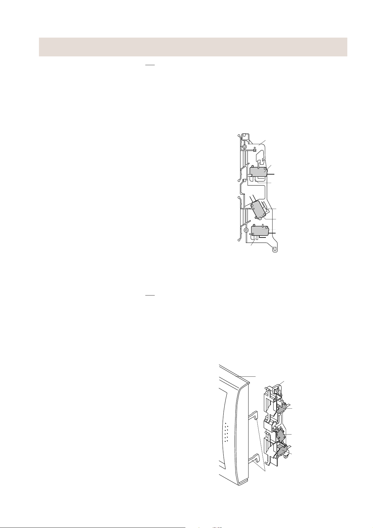
DEPOSE DU COMMUTATEUR DU LOQUET DE CONTROLE, DU COMMUTATEUR
DE CONTROLE ET DU COMMUTATEUR D’ARRET
1. EFFECTUER LES VERIFICATIONS
3D.
2. Débrancher les fils conducteurs des commutateurs et
du panneau de commande.
3. Déposer l’ensemble de panneau de commande de la
bride avant de la cavité du four, en se rapportant au
chapitre “DEPOSE DE L’ENSEMBLE DE PANNEAU
DE COMMANDE”.
4. Déposer les deux (2) vis fixant le crochet de loquet à
la bride du four.
5. Déposer l’ensemble de crochets de loquet de la bride
du four.
6. Pour déposer le commutateur.
6-1. En appuyant vers l’extérieur sur la languette qui
maintient le commutateur, faire tourner le
commutateur de sorte que le montant soit dans l’axe.
6-2. Tirer le commutateur hors du crochet de loquet. ne pas
casser le montant ou la languette du crochet de loquet.
6-3. Maintenant, le commutateur est libre.
Remontage
1. Remonter chaque commutateur à sa place. Le
commutateur du loquet de contrôle est dans la position
inférieure et le commutateur de contrôle est dans la
position intermédiaire. Le commutateur d’arrêt est
dans la position supérieure.
2. Raccorder les fils conducteurs à chaque commutateur.
Se reporter au chapitre “Diagramme schématique”.
3. Fixer le crochet de loquet (avec deux (2) vis de montage) à la bride du four.
4. Remonter l’ensemble de panneau de commande à la
bride avant de la cavité du four.
5. Raccorder les fils conducteurs à l’unité de commande.
Se reporter au chapitre “Diagramme schématique”.
6. Veiller à ce que le commutateur de contrôle fonctionne
correctement et vérifier la continuité du circuit de
contrôle. Se reporter au chapitre “Procédure de test”, et
à “Procédure de réglage” ci-dessous.
Latch hook
Crochet de loquet
SW3: Stop switch
SW3 : commutateur
d’arrêt
Tab
Languette
Tab
Languette
SW2: commutateur
SW2: Monitor switch
de contrôle
SW1: commutateur
SW1: Monitored latch switch
du loquet de contrôle
Tab
Languette
Figure C-2. Dépose des commutateurs de loquet
REGLAGE DU COMMUTATEUR DU LOQUET DE CONTROLE, DU COMMUTATEUR
DE CONTROLE ET DU COMMUTATEUR D’ARRET
1. EFFECTUER LES VERIFICATIONS
3D.
Si le commutateur de loquet de contrôle, le commutateur
de contrôle et le commutateur d’arrêt ne fonctionnent pas
correctement à cause d’un mauvais réglage, l’ajustement
suivant doit être effectué.
2. Desserrer les deux (2) vis fixant le crochet de loquet à
la bride avant de la cavité du four.
3. La porte étant fermée, ajuster le crochet du loquet en
le déplaçant en avant et en arrière, et du haut vers le
bas. Le jeu d’entrée et de sortie de la porte permis par
le crochet de loquet doit être inférieur à 0,5 mm. La
position horizontale du crochet de loquet doit être
réglée de sorte que le commutateur de contrôle soit
activé avec la porte fermée. La position verticale du
crochet de loquet doit être réglée de sorte que le
commutateur d’arrêt et le commutateur de loquet de
contrôle soient activés avec la porte fermée.
4. Fixer les vis fermement.
5. Vérifier le fonctionnement de tous les commutateurs.
Si tous les commutateurs n’ont pas été activés avec la
porte fermée, desserrer la vis et régler la position du
crochet de loquet.
Après le réglage, vérifier les points suivants:
1. Le jeu d’entrée et de sortie reste inférieur à 0,5 mm
lorsque la porte est fermée et verrouillée. Vérifier d’abord
la position supérieure du crochet de loquet, en enfonçant
et tirant la partie supérieure de la porte vers la face du
four. Ensuite, vérifier la position inférieure du crochet de
loquet, en enfonçant et tirant la partie inférieure de la
porte vers la face du four. Les deux résultats (de jeu de
la porte) doivent être inférieurs à 0,5 mm.
Le commutateur du loquet de contrôle et le commutateur
2.
d’arrêt coupent le circuit avant que la porte puisse être ouverte.
3. Les contacts du commutateur de contrôle (COM-NC)
se ferment lorsque la porte est ouverte.
4. Réinstaller le boîtier extérieur et vérifier les fuites de
micro-ondes autour de la porte en utilisant un appareil
de contrôle de micro-ondes agréé. (Se reporter à
“Procédure de mesure des micro-ondes”.)
Door
Porte
Tête de loquet
Latch hook
Têtes de loquet
Latch heads
SW3 : commutateur d’arrêt
SW3: Stop switch
SW2: commutateur de
SW2: Monitor switch
SW1: commutateur de
SW1: Monitored
Figure C-3. Réglages du commutateur de loquet
21
contrôle
loquet de contrôle
latch switch
Page 24
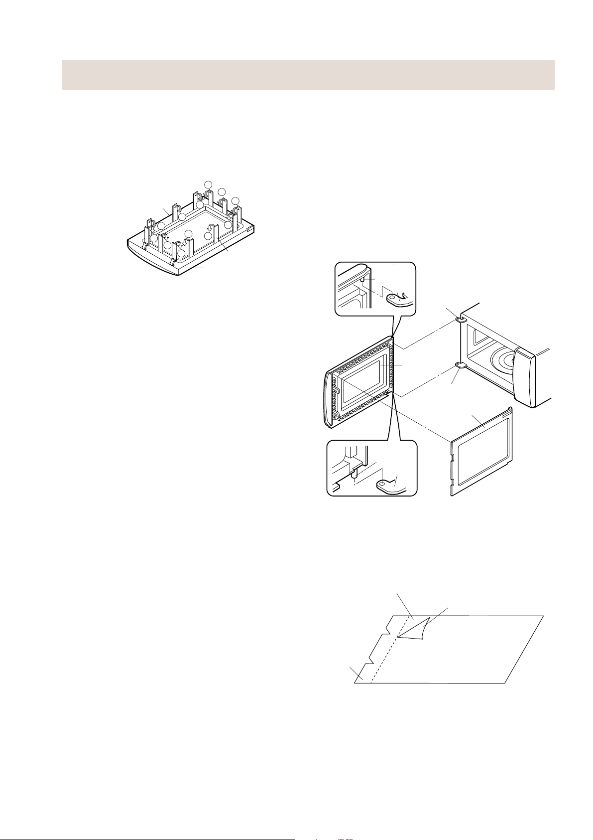
REMPLACEMENT DE LA PORTE
DEPOSE
1. Débrancher le cordon d’alimentation.
2. Ouvrir légèrement la porte.
3.
Insérer une plaque de fer (d’une épaisseur de 0,5 mm environ) ou
un tournevis à lame plate dans l’écartemententre le joint de porte
et le panneau de porte commeillustré sur la figure pour libérer la
pièce engagée, enprenant soin de ne pas casser les attaches.
4. Dégager le couvercle de maintien du panneau de porte.
5. Maintenant, le couvercle de maintien est libre.
Couvercle
de maintien
Choke Cover
7
6
5
Figure C-4. Démontage de la porte
6. Dégager les deux (2) broches du panneau de porte des
deux (2) trous des charnières supérieure et inférieure
du four en soulevant.
7.
Maintenant le panneau de porte est dégagé de la cavité du four.
8. Dégager le panneau de porte des languettes du cadre
de porte et déposer le cadre de porte en faisant glisser
le panneau de porte vers le bas.
9. Maintenant, le panneau de porte avec film de protection intérieur est libre.
Arracher le film de protection intérieur du panneau de porte.
10.
11.Maintenant le panneau de porte est libre.
12.Faire glisser la tête de loquet vers le haut et la déposer
du cadre de porte en dégageant le ressort de loquet du
cadre de porte et de la tête de loquet.
13.
Maintenant la tête de loquet et le ressort de loquet sont libres.
14.Déposer la cale de vitre en enlevant la (1) vis la fixant
au cadre de porte.
15.Déposer la vitre de la porte extérieure du cadre de
porte en la faisant glisser.
16.Maintenant la vitre de la porte extérieure et le cadre de
porte sont libre.
REMONTAGE
1. Remonter la vitre de la porte extérieure sur le cadre de
porte à l’aide de la cale de vitre.
2. Fixer la cale de vitre avec une (1) vis.
3. Remonter le ressort de loquet sur la tête. Remonter le
ressort de loquet sur le cadre de porte. remonter la tête
de loquet sur le cadre de porte.
4. Remonter le panneau de porte sur le cadre de porte en
plaçant les languettes du cadre de porte dans les trous
du panneau de porte.
5. Placer un film de protection sur le panneau de porte. Se
rapporter à “Film de protection intérieur” et à la figure
C-6, pour la manipulation du nouveau film.
6.
Introduire les deux (2) broches du panneau de porte dans les
deux (2) trous des charnières supérieure et inférieure du four.
7. Remonter le couvercle de maintien sur le panneau de
porte en appuyant.
Remarque: Après toute réparation de la porte;
(A) Veiller à ce que les commutateurs du loquet de
contrôle, du commutateur d’arrêt et du commutateur
de contrôle fonctionnent correctement. (Se rapporter
au chapitre “Procédures de test”.)
(B) Un appareil de contrôle des micro-ondes agréé doit
être utilisé pour vérifier la conformité aux normes
standard sur les radiations des micro-ondes.
Après toute réparation, contrôler les points suivants:
1. Les têtes de loquet de la porte doivent accrocher facilement
le crochet de loquet à travers les trous de loquet et la tête
de loquet doit passer par le centre du trou de loquet.
2. L’écart de l’alignement de la porte de la ligne horizontale
de la plaque avant de la cavité doit être inférieur à 1,0 mm.
8
3
4
10
11
9
1
2
Putty Knife
Door Frame
Cadre de porte
12
Couteau à
mastiquer
3. La porte est positionnée avec la face appuyée contre
la plaque avant de la cavité du four.
4.
Vérifier s’il n’y a pas de fuites de micro-ondes autour de la porte
à l’aide d’un appareil de mesure des micro-ondes agréé. (Se
reporter à la Procédure de mesure des micro-ondes.)
Remarque:
La porte d’un four à micro-ondes est conçue pour
agir comme une protection électronique empêchant
les fuites d’énergie de micro-ondes de la cavité du
four pendant le cycle de cuisson. Cette fonction ne
nécessite pas que la porte soit étanche à l’air, à
l’humidité (condensation) ou à la lumière. Dès lors,
l’apparence occasionnelle d’humidité, de lumière,
ou la sensation d’un léger mouvement d’air chaud
autour de la porte du four n’est pas anormale, et
celles-ci n’indiquent pas d’elles-mêmes une fuite
d’énergie de micro-ondes de la cavité du four.
Char-
Upper
nière
supé-
Oven
Broche
Pin
rieure
Hinge
du four
Charnière
Upper Oven
supérieure
Hinge
du four
Panneau
Door Panel
de porte
Charnière
Lower Oven
inférieure
Hinge
du four
Couvercle
Choke Cover
de maintien
Charnière
Lower
infé-
Pin
Oven
rieure
Broche
du four
Hinge
Figure C-5. Remplacement de la porte
FILM DE PROTECTION INTERIEUR
Installation
1. Décoller le film de fond.
3. Placer le côté collant du film de protection intérieur sur
le panneau de porte.
Film de porte
Door film
Backing film
Film de fond
Languette
Finger tab
de prise
Dépose
1. Arracher le film de porte du panneau de porte.
2. Maintenant, le film de porte est libre.
Installation
1. Décoller le film de fond.
2.
Placer le côté collant du film de porte sur le panneau de porte.
Dépose
1. Retirer le film de porte des attaches du cadre de porte.
Installation
1.
Fixer le film de protection aux attaches sur le cadre de porte.
22
Page 25

MESURE DES MICRO-ONDES
Après avoir réglé séparément ou dans l’ensemble, les
commutateurs de gâche, le commutateur de contrôle et la
porte, vérifier avec un appareil de contrôle s’il n’y a pas de
fuites. Il faut s’assurer que les résultats répondent aux
exigences des normes de performance pour les fours à
micro-ondes.
CONDITIONS EXIGEES
Le commutateur de sécurité doit pouvoir empêcher
l’émission de radiation des micro-ondes dépassant 5 mW/
2
à une distance de 5 cm ou plus de la surface externe
cm
du four.
PREPARATIONS POUR UNE VERIFICATION:
Avant de commencer les vérifications effectives de fuite,
procéder de la façon suivante;
1. S’assurer que l’appareil fonctionne normalement selon
les instructions spécifiées dans le mode d’emploi.
Important:
Pour la vérification, utiliser des appareils de contrôle
conformes aux conditions prescrites par les normes de
performance pour les fours à micro-ondes.
Les appareils recommandés sont:
NARDA 8100
NARDA 8200
HOLADAY HI 1500
SIMPSON 380M
2. Placer le plateau du four dans la cavité du four.
3. Placer la charge de 275 ± 15 ml d’eau à une température
de 20 ± 5˚C au centre du plateau du four. Le récipient
d’eau doit être bas et doit avoir une contenance de 600
ml, avec un diamètre intérieur d’environ 8,5 cm et fait
d’un matériau électriquement non-conducteur tel que
du verre ou du plastique.
La mise en place dans le four de cette charge est
importante, non seulement pour protéger le four, mais
aussi pour s’assurer que n’importe quelle fuite pourra
être mesurée avec précision.
4. Fermer la porte et mettre le four en marche avec la
minuterie réglée sur quelques minutes. Si l’eau commence à bouillir avant que le contrôle ne soit terminé,
la remplacer par 275 ml d’eau froide.
5. Déplacer lentement la sonde (pas plus vite que 2,5 cm
/sec.) le long de l’interstice.
6. L’émission de radiation des micro-ondes doit être
mesurée à n’importe quel point situé à une distance de
5 cm ou plus de la surface externe du four.
SHARP
mW cm
mW cm
2
2
Microwave leakage measurement at 5 cm distance
Mesure d’une fuite de micro-ondes à une distance de 5 cm
23
Page 26

DONNEES DE TEST EN UN COUP D’OEIL
PIÈCES SYMBOLE VALEUR / DONNÉES
Fusible F1 F 8A 250 V
Coupe-circuit thermique (FOUR)
Lampe du four OL 240–250 V 25 W E14
Condensateur haute tension C 0,91µF AC 2100 V
Magnétron MG Filament < 1Ω / Filament – chassis ∞ ohm.
Transformateur haute T Enroulement du filament < 1Ω
tension Enroulement secondaire env. 140 Ω
AVERTISSEMENT: DEBRANCHER LA PRISE LORS DE LA MESURE DE LA RESISTANCE.
TC 125°C
Enroulement primaire env. 2,4 Ω
Coupe-circuit thermique intégré. Ouvert 150±5˚C Fermé 90˚C
EARTH
G-Y
SCHEMA
TERRE
EARTH
G-Y
TERRE
SCHEMA
L
F1: FUSIBLE
F1: FUSE
(F6A)
(F8A)
N
L
F1: FUSIBLE
F1: FUSE
(F6A)
(F8A)
N
FILTRE ANTIPARASITES TC: COUPE-CIRCUIT
680K/ 0.5W
0.22µ/AC250V
FILTRE ANTIPARASITES
680K/ 0.5W
0.22µ/AC250V
REMARQUE : CONDITION DU FOUR
1. PORTE FERMEE.
2. MINUTERIE DESACTIVEE.
BRN
50Hz
˜
LIVENEUTRAL
PHASE
230V
NEUTRE
BLU
REMARQUE : CONDITION DU FOUR
1. PORTE FERMEE.
2. NIVEAU DE PUISSANCE DES
MICRO-ONDES 800 W.
3. MINUTERIE ACTIVEE.
BRN
50Hz
˜
LIVENEUTRAL
PHASE
230V
NEUTRE
BLU
NOISE FILTER
NOISE SUPPRESSION COIL
BOBINE DE SUPPRESSION
DES PARASITES
0.0033µ/ 250V 0.0033µ/ 250V
NOISE FILTER
NOISE SUPPRESSION COIL
BOBINE DE SUPPRESSION
DES PARASITES
0.0033µ/ 250V 0.0033µ/ 250V
REMARQUE: “
” indique les pièces utilisées à des tensions
supérieures à 250 V.
TC: OVEN THERMAL
THERMIQUE DU
CUT-OUT
125˚C
FOUR 125°C
COM. N.O.
RY-2
B1
N.O.
SW3: STOP
SW3: COMMUTATEUR
SWITCH
D’ARRET
SW1: MONITORED
SW1: COMMUTATEUR
LATCH SWITCH
DE LOQUET DE
CONTROLE
A1
RY-1
B2
FM
FAN MOTOR
OVEN LIGHT
MOTEUR DU
VENTILATEUR
ECLAIRAGE
SW2: MONITOR
SW2: COMMUTATEUR
OL
DU FOUR
DE CONTROLE
SWITCH
TTM
TURNTABLE MOTOR
MOTEUR DU PLATEAU TOURNANT
COM.
10M/ 0.5W
A3
CONTROL UNIT
UNITE DE COMMANDE
A5
Figure O-1. Schéma du four-Condition d’ARRET
TC: COUPE-CIRCUIT
TC: OVEN THERMAL
THERMIQUE DU
CUT-OUT
125˚C
FOUR 125°C
COM. N.O.
RY-2
B1
N.O.
SW3: STOP
SW3: COMMUTATEUR
SWITCH
D’ARRET
SW1: COMMUTATEUR
SW1: MONITORED
DE LOQUET DE
LATCH SWITCH
CONTROLE
A1
RY-1
B2
FM
FAN MOTOR
MOTEUR DU
VENTILATEUR
ECLAIRAGE
SW2: COMMUTATEUR
SW2: MONITOR
OL
OVEN LIGHT
DU FOUR
DE CONTROLE
SWITCH
TTM
TURNTABLE MOTOR
MOTEUR DU PLATEAU TOURNANT
COM.
10M/ 0.5W
A3
CONTROL UNIT
UNITE DE COMMANDE
A5
N.O.
N.O.
T: TRANSFORMATEUR
T: HIGH VOLTAGE
HAUTE TENSION AVEC
TRANSFORMER
THERMOSTAT 150°C
WITH 150˚C THERMOSTAT
EN ENROULEMENT
IN PRIMARY WINDING
PRIMAIRE
N.C.
T: TRANSFORMATEUR
T: HIGH VOLTAGE
HAUTE TENSION AVEC
TRANSFORMER
THERMOSTAT 150°C
WITH 150˚C THERMOSTAT
EN ENROULEMENT
IN PRIMARY WINDING
PRIMAIRE
N.C.
C:
H.V. CAPACITOR
CONDENSATEUR
0.91µF/ AC2100V
H.T. 0,91°F/CA 2100 V
C:
H.V. CAPACITOR
CONDENSATEUR
0.91µF/ AC2100V
H.T. 0,91°F/CA 2100 V
MG: MAGNETRON
MG : MAGNETRON
H.V. RECTIFIER
REDRESSEUR H.T.
MG: MAGNETRON
MG : MAGNETRON
H.V. RECTIFIER
REDRESSEUR H.T.
Figure O-2. Schéma du four-Condition de MARCHE
24
Page 27

DIAGRAMME SCHEMATIQUE
25
CONTROL UNIT
UNITE DE COMMANDE
15
CN-A
RY2
WHT
CN-B
BLK
TC: COUPE-CIRCUIT
SW3: STOP SWITCH
SW3: COMMUTATEUR D’ARRET
N.O.
COM.
RED
BLK
TC: THERMAL CUT-OUT
(OVEN)
CN-A
1
WHT
2
3
BLK
T1
4
5
WHT
BLK
BLK
CN-B
RED
2
BLU
1
RED
THERMIQUE (FOUR)
WHT
WHT
OL: LAMPE
OL: OVEN
DU FOUR
LAMP
BRN
BLU
LIVE
PHASE
NEUTRAL
NEUTRE
NOISE FILTER
FILTRE ANTIPARASITES
L
N
POWER SUPPLY CORD
CORDON D’ALIMENTATION
G/Y
RED
WHT
BLK
SP1
BLK
BLK
BLK
N.C.
SW2: MONITOR
SW2: COMMUTATEUR
DE CONTROLE
SWITCH
COM.
SW1: COMMUTATEUR
SW1: MONITORED
DU LOQUET DE
LATCH SWITCH
CONTROLE
BLK
BLK
N.O.
WHT
COM.
WHT
WHT
WHT
TTM: MOTEUR DU
TTM: TURNTABLE
PLATEAU
MOTOR
TOURNANT
WHT
WHT
RED
RED
BLK
WHT
FM:
FM: MOTEUR DU
FAN MOTOR
VENTILATEUR
BLK
WHT
COMPOSANTS A HAUTE TENSION
HIGH VOLTAGE COMPONENTS
MG : MAGNETRON
MG: MAGNETRON
H.V.WIRE B
FIL H.T. B
C:
H.V.
CONDENSA-
CAPACITOR
TEUR H.T.
T: HIGH VOLTAGE
T: TRANSFORMA-
TRANSFORMER
TEUR H.T.
H.V.WIRE A
FIL H.T. A
H.V.
REDRESSEUR
RECTIFIER
H.T.
Figure S-1. Diagramme schématique
Page 28

CIRCUIT DU PANNEAU DE COMMANDE
STOP
SWITCH
COMMUTATEUR
B 2
Q40
D’ARRET
B 1
SP1
R40 3.3k
DTA143ES
+
Q2
DTA123ES
ZD1 HZ6A3
D30
C5 0.1µ/50v
C4 47µ/16v
–
Q1
2SB1238
R2 2k 1/2w
C2 0.1µ/50v
D20
C3
R3 4.7k
ZD2 HZ4A2
R1 100 2w
R30 4.7k
C30
VC
(JF) 4.7k
R31 15k
SS
SS
RESET
9
CNV
INT0
C11
R11 4.7k
CF1 4MHz
10
11 XOUT
12 XIN
13 V
14 VDD
15 N.F
16
P22
817INT1
Q22
7 P21
18AIN0
RY2
DTA143ES
TRANSFORMATEUR
HAUTE TENSION
HIGH
VOLTAGE
TRANSFORMER
NO
COM
D22D21
(JB)
(JC)
R20 4.7k
2D4
3D5
4D6
5D7
6 P20
I-1
IZA948DR
19AIN1
20AIN2
21AIN3
22P00
23P01
RY1
Q20
DTA143ES
C20
0.1µ/50v
1D3
24P02
AC
A 3
ZD3 HZ12A3
32D2
31D1
30D0
29P13
28P12
27P11
26P10
25P03
LAMPE DU FOUR
MOTEUR DU
MOTEUR DU PLATEAU
VENTILATEUR
TOURNANT
OVEN LAMP
FAN MOTOR
TURNTABLE
MOTOR
A 1
Q21
Q24
2SB1238
(JD)
R10 1k 1/2w
(A)
DTD143ES
10µ/35v
C21
–
+
: IF NOT SPECIFIED 1/4W ± 5%
: IF NOT SPECIFIED 1SS270A
: IF NOT SPECIFIED 0.01µF/16V
: SI NON SPECIFIE 1/4 W ± 5 %
: SI NON SPECIFIE 1SS 270 A
: SI NON SPECIFIE 0,01 _F/16 V
NOTE
REMARQUE
R57 150
R56 150
R55 150
R54 150
R53 150
R52 150
R51 150
R50 150
DTB123ES
Q53
LD16
LD15
LD14
LD13
LD12
LD11
LD10
LD24
LD23
LD22
LD21
LD20
LD19
LD18
LD8
LD7
LD6
LD5
LD4
LD3
LD2
LD1LD9LD17LD30
LD34
LD33
LD32
LD31
Figure S-2. Circuit du panneau de commande
T1
D3
D1
(A)
–
+
D2
10G471K
VRS1
a
c
AC230V
50Hz
AC 230 V
50 Hz
D4
C1 470µ/35v
A 5
AC
D1-D4
d
b
1N4005E
(J1)
0.1µ/50v
C10
Q10
DTA143ES
(J6)
(J4)
(J2)(J3)
(J7)
(J5)
26
(JE)
SW2
R70 15k
DTB123ES
Q52
DTB123ES
Q51
DTB123ES
Q50
C60
C61
R63 4.7k
R62 4.7k
R60 10k
A
CB
R61 10k
SW1
Page 29

SCHEMA DE CABLAGE
LD30
E
B
Q50
B
BE
9
10
LD3
LD2
LD1
17
R63
LD24
C60
363534
R51
Q51
LD4
E
7
Q52
LD23
Q53
LD22
R50
1
3
B
5
LD6
SW1
28
LD32
6
LD7
12
C61
R61
ABC
18
19
LD21
LD31
E
LD5
R52
SW2
8
13
R60
LD20
LD33
4
LD8
LD9
R62
(JE)
16
LD18
LD19
R54
27262524232221
LD10
15
R70
2
14
LD17
R53
LD34
LD11
11
LD16
R55
20
LD12
R56
LD13
LD14
LD15
R57
3332313029
Q2
D30
C21
24
25
17
32
(JF)
R20
1
9
8
C20
B
D20
B
E
Q23
2
Q20
RY1
16
IC-1
CF1
B
E
1
CN - B
RY3 RY2
B
R10
VRS1
DIP
SP1
CHINGSENG
C - 02V0
C10
C2
D4
D3
D2
D1
R40
(J3)
(J5)
(J7)
38
39
B
(J2)
(J4)
Q40
E
44
R2
ZD1
R1
C1
E
E
Q10
B
4
5
T1
37
R31
C30
(J6)
Q1
S
C4
42
C5
ZD2
C3
R3
43
B
R30
45
C11
R11
E
ZD3
E
Q21
B
Q24
(JD)
3
P
1
(J1)
Figure S-3. Plaquette de circuit imprimé
,F
40
41
B
(JB)
(JA)
Q22
E
(JC)
D21
D23
GRILL MICRO
D22
CN - A
15
27
Page 30

LISTE DES PIECES
Remarque: Les pièces marquées de “∆” risquent de provoquer une exposition à l’énergie des micro-ondes. /Les pièces
marquées “*” sont utilisées pour des tensions supérieures à 250 V. / Marque “§” section de livraison des pièces détachées.
NO. REF. NO. PIECE § DESCRIPTION Q'TE
PIECES ELECTRIQUES
1- 1 RH-DZA048WRE0 U Redresseur haute tension 1 AM
1- 2 FPWBFA308WRE2 U Filtre antiparasite 1 AQ
1- 3 QACCVA006URE1 U Cordon d’alimentation 1 AL
C RC-QZA237WRE0 U Condensateur haute tension 1 AR
F1 QFS-CA025WRE0 U Fusible F8A 1 AC
FM RMOTEA339WRE2 U Moteur du ventilateur 1 AU
MG RV-MZA270WRE0 U Magnétron 1 BG
OL RLMPTA066WRE0 U Lampe du four 1 AK
SW1 QSW-MA131WRE0 J Commutateur de loquet de contrôle 1 AK
SW2 QSW-MA133WRE0 U Commutateur de contrôle 1 AN
SW3 QSW-MA131WRE0 J Commutateur d’arrêt 1 AK
T RTRN-A014URE0 U Transformateur haute tension 1 BE
TC RTHM-A096WRE0 U Coupe-circuit thermique 125˚C (FOUR) 1 AL
TTM RMOTDA226WRE0 U Moteur du plateau tournant 1 AQ
PIECES DU BOITIER
2- 1 GCABUA573WRT0 U Boîtier extérieur R-212(W) 1 AT
2- 1 GCABUA003URP0 U Boîtier extérieur R-212(G) 1 AT
2- 1 GCABUA011URP0 U Boîtier extérieur R-212(BL) 1 AT
2- 1 GCABUA025URP0 U Boîtier extérieur R-212(Y) 1 AT
2- 2 GLEGPA057WRE0 U Pied 2 AB
PIECES DU PANNEAU DE COMMANDE
3- 1 DPWBFB919WRK0 U Unité de commande 1 BD
3- 1A QCNCMA430DRE0 U Connecteur à 3 broches (CN-A) 1 AC
3- 1B QCNCMA414DRE0 U Connecteur à 2 broches (CN-A) 1 AB
C1 VCEAB31VW477M U Condensateur 470 uF 35 V 1 AB
C2 RC-KZA087DRE0 U Condensateur 0,1 uF 50 V 1 AB
C3 VCKYD11CY103N U Condensateur 0,01 uF 16 V 1 AA
C4 VCEAB31CW476M U Condensateur 47 uF 16 V 1 AA
C5 RC-KZA087DRE0 U Condensateur 0,1 uF 50 V 1 AB
C10 RC-KZA087DRE0 U Condensateur 0,1 uF 50 V 1 AB
C11 VCKYD11CY103N U Condensateur 0,01 uF 16 V 1 AA
C20 RC-KZA087DRE0 U Condensateur 0,1 uF 50 V 1 AB
C21 VCEAB31VW106M U Condensateur 10 uF 35 V 1 AB
C30 VCKYD11CY103N U Condensateur 0,01 uF 16 V 1 AA
C60-61 VCKYD11CY103N U Condensateur 0,01 uF 16 V 2 AA
CF1 RCRS-A012DRE0 U Résonateur céramique (CST4,00MGW) 1 AD
D1-4 VHD1N4005E1-2 U Diode (1N4005E) 4 AB
D20-22 VHD1SS270A/-1 U Diode (1SS270ATA) 3 AA
D30 VHD1SS270A/-1 U Diode (1SS270ATA) 1 AA
I-1 RH-IZA948DRE0 U Circuit LSI 1 AQ
LD1-24 VHPLTL1CHE/-3 U Diode électroluminescente (DEL) 24 AC
LD30-34 VHPLTL1CHE/-3 U Diode électroluminescente (DEL) 5 AC
Q1 VS2SB1238//-3 U Transistor (2SB1238) 1 AD
Q2 VSDTA123ES/-3 U Transistor (DTA123ES) 1 AB
Q10 VSDTA143ES/-3 U Transistor (DTA143ES) 1 AB
Q20 VSDTA143ES/-3 U Transistor (DTA143ES) 1 AB
Q21 VSDTD143ES/-3 U Transistor (DTD143ES) 1 AB
Q22 VSDTA143ES/1B U Transistor (DTA143ES) 1 AB
Q24 VS2SB1238//-3 U Transistor (2SB1238) 1 AD
Q40 VSDTA143ES/-3 U Transistor (DTA143ES) 1 AB
Q50-53 VSDTB123ES/-3 U Transistor (DTB123ES) 4 AB
R1 VRS-L63DA101J U Résistance 100 ohms 2 W 1 AA
R2 VRD-B12HF202J U Résistance 2,0k ohm 1/2 W 1 AA
R3 VRD-B12EF472J U Résistance 4,7k ohm 1/4 W 1 AA
R10 VRD-B12HF102J U Résistance 1,0k ohm 1/2 W 1 AA
R11 VRD-B12EF472J U Résistance 4,7k ohm 1/4 W 1 AA
R20 VRD-B12EF472J U Résistance 4,7k ohm 1/4 W 1 AA
R30 VRD-B12EF472J U Résistance 4,7k ohm 1/4 W 1 AA
R31 VRD-B12EF153J U Résistance 15k ohm 1/4 W 1 AA
R40 VRD-B12EF332J U Résistance 3,3k ohm 1/4 W 1 AA
R50-57 VRD-B12EF151J U Résistance 150 ohm 1/4 W 8 AA
R60-61 VRD-B12EF103J U Résistance 10k ohm 1/4 W 2 AA
R62-63 VRD-B12EF472J U Résistance 4,7k ohm 1/4 W 2 AA
R70 VRD-B12EF153J U Résistance 15k ohm 1/4 W 1 AA
(JF) VRD-B12EF472J U Résistance 4,7k ohm 1/4 W 1 AA
RY1 RRLY-A111DRE0 U Relais (JV12S-KT) 1 AL
RY2 RRLY-A105DRE0 U Relais (OMIF-S-112LM) 1 AL
SP1 RALM-A014DRE0 U Sonnerie (PKM22EPT) 1 AG
SW1 RVR-BA018WRE0 U Encodeur rotatif 1 AH
SW2 QSW-PA016DRE0 U Commutateur sensitif 1 AB
T1 RTRNPA121DRE0 U Transformateur 1 AM
VRS1 RH-VZA032DRE0 U Varistance (10G471K) 1 AC
ZD1 VHEHZ6A3///-1 U Diode zener (HZ6A3) 1 AB
CODE
*
*
∆
*
*
∆
∆
∆
∆
28
Page 31

LISTE DES PIECES
PARTS LIST
Remarque: Les pièces marquées de “∆” risquent de provoquer une exposition à l’énergie des micro-ondes. /Les pièces
§
marquées “*” sont utilisées pour des tensions supérieures à 250 V. / Marque “
NO. REF. NO. PIECE § DESCRIPTION Q'TE
ZD2 VHEHZ4A2///-1 U Diode zener (HZ4A2) 1 AB
ZD3 VHEHZ12A3//-1 U Diode zener (HZ12A3) 1 AB
3- 1- 1 LHLD-A008URF0 U Support de DEL 1 AE
3- 1- 2 PSHEPA028URE0 U Feuille de minuterie 1 AD
3- 1- 3 XEPSD30P10XS0 U Vis; 3 mm x 10 mm 2 AA
3- 2 HPNLCG006URR0 U Panneau de commande [R-212(G)] 1 AN
3- 2 HPNLCL007URR0 U Panneau de commande [R-212(BL)] 1 AN
3- 2 HPNLCW025URR0 U Panneau de commande [R-212(W)] 1 AN
3- 2 HPNLCY006URR0 U Panneau de commande [R-212(Y)] 1 AN
3- 3 JBTN-G004URF0 U Touche de sélection de mode [R-212(G)] 1 AE
3- 3 JBTN-L003URF0 U Touche de sélection de mode [R-212(BL)] 1 AE
3- 3 JBTN-W022URF0 U Touche de sélection de mode [R-212(W)] 1 AE
3- 3 JBTN-Y002URF0 U Touche de sélection de mode [R-212(Y)] 1 AE
3- 4 JKNBKG001URF0 U Bouton de minuterie [R-212(G)] 1 AE
3- 4 JKNBKL001URF0 U Bouton de minuterie [R-212(BL)] 1 AE
3- 4 JKNBKW001URF0 U Bouton de minuterie [R-212(W)] 1 AE
3- 4 JKNBKY003URF0 U Bouton de minuterie [R-212(Y)] 1 AE
3- 5 XEPSD30P10XS0 U Vis; 3 mm x 10 mm 1 AA
” section de livraison des pièces détachées.
CODE
PIECES DU FOUR
4- 1 DOVN-A013URT0 U Cavité du four 1 BA
4- 2 LBNDKA111WRP0 U Support de condensateur H.T. 1 AD
4- 3 PHOK-A001URF0 U Crochet de loquet 1 AH
4- 4 NFANJA029WRE0 U Pale de ventilateur 1 AM
4- 5 PDUC-A638WRF2 U Conduit de ventilateur 1 AE
4- 6 LANGFA169WRP6 U Support de châssis 1 AE
4- 7 PPACGA126WRE0 U Joint d’étanchéité 1 AC
4- 8 PCUSGA317WRP0 U Coussinet de transformateur H.T. 1 AA
4- 9 PCOVPA309WRE0 U Cache de guide d’ondes 1 AC
4-10 PDUC-A581WRF3 U Conduit d’admission d’air 1 AE
4-11 GDAI-A280WRP1 U Plaque de base 1 AQ
4-12 PSPAGA001WRE0 U Coussinet anti-vibrations 1 AA
PIECES DE LA PORTE
5- 1 FDORFA299WRT1 U Ensemble de panneau de porte 1 AU
5- 2 GCOVHA366WRF0 U Couvercle de maintien 1 AG
5- 3 GWAKPL003URF0 U Cadre de porte R-212(BL) 1 AT
5- 3 GWAKPG006URF0 U Cadre de porte R-212(G) 1 AT
5- 3 GWAKPW023URF0 U Cadre de porte R-212(W) 1 AT
5- 3 GWAKPY003URF0 U Cadre de porte R-212(Y) 1 AT
5- 4 PGLSPA003URE0 U Vitre de porte extérieure 1 AL
5- 5 LSTPPA013URF0 U Tête de loquet 1 AD
5- 6 MSPRTA141WRE0 U Ressort de loquet 1 AA
5- 7 PSHEPA482WRE0 U Film de protection intérieur 1 AH
5- 8 LSTPPA012URF0 U Cale de vitre 1 AB
5- 9 XEBSD30P06000 U Vis : 3 mm x 6 mm 5 AA
DIVERS
6- 1 FROLPA070WRK3 U Support de plateau tournant 1 AM
6- 2 NTNT-A060WRE0 U Plateau tournant 1 AN
6- 3 TINS-A134URR0 U Mode d’emploi/livre de recettes R-212( ) & R-212( )E 1 AM
6- 3 TINS-A153URR0 U Mode d’emploi/livre de recettes R-212( )N 1 AM
6- 3 TINS-A142URRO U Mode d’emploi/livre de recettes R-212( )D 1 AM
6- 4 QW-QZA191WRE0 U Fil haute tension A 1 AF
6- 5 QW-QZA001URE0 U Fil haute tension B 1 AE
6- 6 FW-VZA058URE0 U Main harness 1 AR
6- 7 TCAUHA006URR0 U Etiquette d’avertissement (non illustrée) 1 AE
6- 8 PCLI-A001URE0 U Attache de faisceau 1 AA
VIS, ECROUS ET RONDELLES
7- 1 XOTSD40P12RV0 J Vis : 4 mm x 12 mm 13 AA
7- 2 XHTSD40P08RV0 J Vis : 4 mm x 8 mm 5 AA
7- 3 LX-LZA011WRE0 U Rivet 1 AB
7- 4 LX-NZA026WRE0 U Ecrou Nyloc M4 1 AA
7- 5 XFPSD40P06000 J Vis : 4 mm x 6 mm 2 AA
7- 6 XOTSD40P10000 J Vis auto-taraudeuse : 4 mm x 10 mm 2 AA
7- 7 XOTSE40P12000 J Vis : 4 mm x 12 mm R-212(W) 2 AA
7- 7 XOTSE40P12000 J Vis : 4 mm x 12 mm R-212(Y) 2 AA
7- 7 XOTSF40P12000 J Vis : 4 mm x 12 mm R-212(BL) 2 AA
7- 7 XOTSF40P12000 J Vis : 4 mm x 12 mm R-212(G) 2 AA
7- 8 LX-CZA063WRE0 U Vis de transformateur H.T. 4 AA
7- 9 XHPSD40P08K00 J Vis : 4 mm x 8 mm 1 AA
7-10 LX-EZA045WRE0 U
Vis de couvercle de moteur de plateau tournant (non illustré)
1AA
COMMANDE DE PIECES DE RECHANGE
Afin d’être livré correctement et rapidement, indiquer les informations suivantes sur votre bon de commande.
∆
∆
∆
∆
∆
∆
∆
*
*
1. NUMERO DE MODELE 2. NO. DE REFERENCE 3. NO. DE LA PIECE 4. DESCRIPTION
29
Page 32

VUE ECLATEE
PIECES DU FOUR
7-1
2-1
7-1
4-10
4-9
4-1
4-7
7-5
OL
TTM
4-11
7-3
7-7
7-1 7-1
TC
7-4
T
4-3
7-1
6-7
7-6
7-2
MG
4-8
SW3
SW2
SW1
7-2
7-6
1-3
1-1
4-2
4-5
6-2
4-4
1-2
7-7
4-6
7-2
7-1
7-2
FM
F1
7-9
6-8
7-5
7-1
2-2
7-1
7-1
4-12
2-2
REMARQUE: Si le couvercle du moteur
du plateau tournant doit être déposé, il
doit être remis en place à l’aide de cette
vis de fixation : LX-EZA045WRE0 (7-10)
7-8
C
6-1
7-1
x4
30
Page 33

VUE ECLATEE
PIECES DU PANNEAU DE COMMANDE
3 - 5
3 - 2
3 - 3
3 - 4
3-1-2
3 - 1
5-9
3-1-3
3-1-1
PIECES DE LA PORTE
5-2
5-3
5-4
5-1
5-6
5-7
5-9
5-9
5-9
5-8
5-9
5-5
31
Page 34

GARNITURES ET ACCESSOIRES
DIVERS
6-4
GARNITURES ET ACCESSOIRES
6-5
6-6
Actual wire harness may be different from illustration.
Le faisceau peut en réalité être différent de l’illustration.
FEUILLE DE PROTECTION
DOOR PROTECTION SHEET
DE PORTE
SPADPA531WRE0
CALE
TOP PAD
SUPERIEURE
FPADBA008URK0
PLATEAU TOURNANT X2
TURNTABLE TRAY X2
COOK BOOK &
LIVRE DE CUISINE &
INSTRUCTION BOOK
MANUEL D’INSTRUCTIONS
SUPPORT DE
ROLLER STAY
PLATEAU TOURNANT
SUPPORT
ACCESSORY HOLDER
D’ACCESSOIRES
*(SPADPA014URE0)
INTO THE OVEN CAVITY (DIAGONALLY)
DANS LA CAVITE DU FOUR (EN DIAGONAL)
Not replaceable items.
Articles non replaçables
SAC DE PROTECTION DU FOUR
OVEN BAG
SSAKHA041WRE0
BOTTOM PAD
CALE INFERIEURE
FPADBA007URK0
PACKING CASE
CARTON D’EMBALLAGE
R-212(W): SPAKCA256URR0
R-212(BL): SPAKCA294URR0
R-212(G): SPAKCA295URR0
R-212(Y): SPAKCA296URR0
R-212(W)D: SPAKCA262URR0
R-212(BL)D: SPAKCA289URR0
R-212(G)D: SPAKCA290URR0
R-212(Y)D: SPAKCA291URR0
R-212(W)E: SPAKCA324URR0
R-212(BL)E: SPAKCA325URR0
R-212(W)N: SPAKCA319URR0
32
’99 SHARP CORP, Imprimé au Royaume-Uni.
Page 35

R-212B
SER VICE MANU AL
S3809R212BPR/
MICROWAVE OVEN
COOKING CONTROL
DEFROST
MED
RICE
MED LOW
MED HIGH
LOW
HIGH
kg/
Light Up Dial
CUP/
2
3
1
4
5
6
7
0
8
9
10
30
11
25
1.0
12
20
13
15
14
4
2
0.5
OPEN DOOR
MODEL
R-212B
In interests of user-safety the oven should be restored to its original
condition and only parts identical to those specified should be used.
TABLE OF CONTENTS
CAUTION, MICROWAVE RADIATION................................................................................................................. 1
WARNING.............................................................................................................................................................. 1
PRODUCT SPECIFICATIONS ............................................................................................................................. 2
GENERAL INFORMATION.................................................................................................................................... 2
APPEARANCE VIEW ........................................................................................................................................... 3
OPERATION SEQUENCE.................................................................................................................................... 4
FUNCTION OF IMPORTANT COMPONENTS .................................................................................................... 5
SERVICING AND TROBLE SHOOTING GUIDE................................................................................................... 6
TEST PROCEDURE ............................................................................................................................................. 8
CONTROL PANEL...............................................................................................................................................14
COMPONENT REPLACEMENT AND ADJUSTMENT PROCEDURE ............................................................... 18
MICROWAVE MEASUREMENT ........................................................................................................................ 24
WIRING DIAGRAM ............................................................................................................................................. 25
PICTORIAL DIAGRAM ....................................................................................................................................... 26
CONTROL PANEL CIRCUIT ...............................................................................................................................27
PRINTED WIRING BOARD .................................................................................................................................28
PARTS LIST ....................................................................................................................................................... 29
SHARP CORPORATION
Page 36

R-212B
Page 37

SERVICE MANUAL
R-212B
MICROWAVE OVEN
R-212B
GENERAL IMPORTANT INFORMATION
This Manual has been prepared to provide Sharp Corp. Service
engineers with Operation and Service Information.
It is recommended that service engineers carefully study the
entire text of this manual, so they will be qualified to render
satisfactory customer service.
CAUTION
MICROWAVE RADIATION
DO NOT BECOME EXPOSED TO RADIATION FROM
THE MICROWAVE GENERATOR OR OTHER PARTS
CONDUCTING MICROWAVE ENERGY.
Service engineers should not be exposed to the microwave
energy which may radiate from the magnetron or other
microwave generating devices if it is improperly used or
connected. All input and output microwave connections,
waveguides, flanges and gaskets must be secured. Never
operate the device without a microwave energy absorbing
load attached. Never look into an open waveguide or
antenna while the device is energized.
PRODUCT SPECIFICATIONS
APPEARANCE VIEW
OPERATING SEQUENCE
FUNCTION OF IMPORTANT
COMPONENTS
SERVICING AND
TROUBLESHOOTING CHART
TEST PROCEDURE
CONTROL PANEL ASSEMBLY
WARNING
Never operate the oven until the following points are ensured.
(A) The door is tightly closed.
(B) The door brackets and hinges are not defective.
(C) The door packing is not damaged.
(D) The door is not deformed or warped.
(E) There is not any other visible damage with the oven.
Servicing and repair work must be carried out only by trained
service engineers.
All the parts marked "*" on parts list are used at voltages more
than 250V.
Removal of the outer wrap gives access to potentials above
250V.
All the parts marked "∆" on parts list may cause undue
microwave exposure, by themselves, or when they are damaged, loosened or removed.
SHARP CORPORATION
OSAKA, JAPAN
COMPONENT REPLACEMENT
AND ADJUSTMENT PROCEDURE
MICROWAVE MEASUREMENT
WIRING DIAGRAM
PARTS LIST
1
Page 38

R-212B
PRODUCT SPECIFICATIONS
ITEM DESCRIPTION
Power Requirements 220 Volts
50 Hertz
Single phase, 3 wire earthed
Power Consumption 1.06 kW
Power Output 700 watts nominal of RF microwave energy (IEC 705)
Operating frequency 2450 MHz
Case Dimensions Width 450 mm
Height295 mm including foot
Depth 355 mm
Cooking Cavity Dimensions Width 288 mm
Height195 mm
Depth 319 mm
Turntable diameter 272 mm
Control Complement Light up dial timer (30 minutes)
Microwave Power for Variable Cooking
Repetition Rate;
HIGH........................... Full power throughout the cooking time
MEDIUM HIGH ............................ approx. 70% of FULL Power
MEDIUM...................................... approx. 50% of FULL Power
MEDIUM LOW............................. approx. 30% of FULL Power
LOW ............................................ approx. 10% of FULL Power
Set Weight (Approx.) 13 kg
GENERAL INFORMATION
WARNING
THIS APPLIANCE MUST BE EARTHED
IMPORTANT
THE WIRES IN THIS MAINS LEAD ARE COLOURED IN ACCORDANCE WITH THE FOLLOWING CODE:
GREEN-AND-YELLOW : EARTH
BLUE : NEUTRAL
BROWN : LIVE
2
Page 39

OVEN
5 6 7
4
APPEARANCE VIEW
10
23
12
9
8
4
R-212B
1
13
11
1. Ventilation openings
2. Oven lamp
3. Door hinges
4. Door safety latches
5. See through door
6. Door seals sealing surfaces
7. Coupling
CONTROL PANEL
COOKING CONTROL
DEFROST
MED LOW
LOW
MED
Light Up Dial
2
1
RICE
MED HIGH
HIGH
kg/
CUP/
3
4
5
6
0
7
8
9
0.5
13
12
10
11
1.0
30
4
25
20
1415
2
DOOR OPEN
8. Door open button
9. Control panel
10.Waveguide cover
11.Power supply cord
12.Turntable
13.Roller stay
VARIABLE COOKING CONTROL
There are five power levels. The approximate
percentage of microwave power for each setting
is:
HIGH 100%
MED HIGH (RICE) 70%
MED 50%
MED LOW (DEFROST) 30%
LOW 10%
LIGHT UP DIAL (0-30 minutes)
Turn to set cooking time, weight of defrost food
or serving of rice.
MEAT DEFROST GUIDE
RICE COOKING GUIDE
3
Page 40

R-212B
OPERATION SEQUENCE
OFF CONDITION
Closing the door activates all door interlock switches
(1st. latch switch, 2nd. interlock relay control switch).
IMPORTANT
When the oven door is closed, the monitor switch contacts
(COM-NC) must be open.
When the microwave oven is plugged in a wall outlet, rated
voltage is supplied to the noise filter and the control unit.
Figure O-1 on page 25
MICROWAVE COOKING CONDITION
HIGH COOKING
Set the variable cooking control to HIGH and set the Light
Up Dial.
Function sequence
Figure O-2 on page 25
CONNECTED COMPONENTS RELAY
Oven lamp, Fan motor, Turntable motor RY1
Power transformer RY2
1. Rated voltage is supplied to the primary winding of the
power transformer. The voltage is converted to about
3.3 volts A.C. output on the filament winding and high
voltage of approximately 2000 volts A.C. on the secondary winding.
2. The filament winding voltage (3.3 volts) heats the
magnetron filament and the high voltage (2000 volts) is
sent to the voltage doubling circuit, where it is doubled
to negative voltage of approximately 4000 volts D.C..
3. The 2450 MHz microwave energy produced in the
magnetron generates a wave length of 12.24 cm. This
energy is channelled through the waveguide (transport
channel) into the oven cavity, where the food is placed
to be cooked.
4. When the cooking time is up, a signal tone is heard and
the relays RY1+RY2 go back to their home position.
The circuits to the oven lamp, power transformer, fan
motor and turntable motor are cut off.
5. When the door is opened during a cook cycle, the
switches come to the following condition.
2nd. interlock relay control switch must open their
contacts first. After that the contacts (COM-NC) of the
monitor switch can be closed.
6-2. When the oven door is closed, the contacts (COM-
NC) of the monitor switch must be opened. After that
the contacts of the 1st. latch switch and 2nd. interlock
relay control switch are closed.
6-3. When the oven door is opened and the contacts of the
1st latch switch and the 2nd. interlock relay remain
closed. The fuse M6.3A will blow, because the monitor switch is closed and a short circuit is caused.
MEDIUM HIGH, MEDIUM, MEDIUM LOW, LOW
COOKING
When the microwave oven is preset for variable cooking
power, rated voltage is supplied to the power transformer
intermittently within a 32-second time base through the
relay contact which is coupled with the current-limiting
relay. The following levels of microwave power are given.
SETTING;
32 sec. ON
HIGH
24 sec. ON
MEDIUM HIGH
18 sec. ON
MEDIUM
12 sec. ON
MEDIUM LOW
6 sec. ON
LOW
NOTE: The ON/OFF time ratio does not exactly corre-
spond to the percentage of microwave power,
because approx. 2 seconds are needed for heating up the magnetron filament.
8 sec. OFF
Approx. 70%
14 sec. OFF
Approx. 50%
20 sec. OFF
Approx. 30%
26 sec. OFF
Approx. 10%
CONDITION
DURING DOOR OPEN
SWITCH CONTACT COOKING
1st. latch switches COM-NO Closed Open
2nd. interlock relay
control switch
Monitor switch COM-NC Open Closed
COM-NO Closed Open
(NO COOKING)
The circuits to the power transformer, fan motor, turntable motor, and the oven lamp are cut off when the 1st.
latch switch, 2nd. interlock relay switch are made open.
6. MONITOR SWITCH CIRCUIT
The monitor switch is mechanically controlled by oven
door, and monitors the operation of the 1st latch switch
and 2nd. interlock relay.
6-1 When the oven door is opened during or after the
cycle of a cooking program, the 1st. latch switch and
4
Page 41

FUNCTION OF IMPORTANT COMPONENTS
R-212B
DOOR OPEN MECHANISM
The door is opened by pushing the open button on the
control panel, refer to the Figure D-1.
When the open button is pushed, the open button pushes
the switch lever up and in turn the latch heads are released
from latch hook. When the latch heads are released, the
switch lever returns to its original position by its own
weight.
DOOR
LATCH
HEADS
SWITCH LEVER
LATCH HOOK
2ND. INTERLOCK
RELAY CONTROL
SWITCH
MONITOR
SWITCH
1ST. LATCH
SWITCH
Figure D-1. Door Open Mechanism
1ST. LATCH SWITCH AND 2ND. INTERLOCK RELAY CONTROL SWITCH SWITCH
1. When the oven door is closed, the contacts (COM-NO)
must be closed.
2. When the oven door is opened, the contacts ( COMNO) must be opened.
2. If the wire harness or electrical components are shortcircuited, the fuse M6.3A blows to prevent an electric
shock of fire hazard.
HIGH VOLTAGE FUSE
The high voltage fuse blows when the high voltage rectifier
or the magnetron is shorted.
TEMPERATURE FUSE 120˚C (OVEN)
The temp. fuse located on the top of the oven cavity is
designed to prevent damage to the oven if the foods in the
oven catch fire due to over heating produced by improper
setting of cook time or failure of control unit. Under normal
operation, the temp. fuse remains closed. However, when
abnormally high temperatures are reached within the
oven cavity, the temp. fuse will open at 120˚C, causing the
oven to shut down. The defective fuse must be replaced
with a new one.
THERMAL CUT-OUT 95˚C (MAGNETRON )
The thermal cut-out located on the top of the oven cavity
is designed to prevent damage to the magnetron if an over
heated condition develops in the tube due to cooling fan
failure, obstructed air guide, dirty or blocked air intake, etc.
Under normal operation, the thermal cut-out remains
closed. However, when abnormally high temperatures are
reached within the magnetron, the thermal cut-out will
open at 95˚C, causing the oven to shut down. When the
magnetron has cooled to 75˚, the thermal cut-out closes
and cook cycle will resume.
MONITOR SWITCH
1. When the oven door is closed, the contacts (COM-NC)
must be opened.
2. When the oven door is opened, the contacts ( COMNC) must be closed.
3. If the oven door is opened and the contacts (COM-NO)
of the 1st latch switch and 2nd. interlock relay fail to
open, the fuse blows simultaneously with closing the
contacts (COM-NC) of the monitor switch.
CAUTION: BEFORE REPLACING A FUSE TEST THE
1ST LATCH SWITCH, 2ND. INTERLOCK
RELAY, 2ND. INTERLOCK RELAY CONTROL SWITCH, MONITOR SWITCH AND
MONITOR RESISTOR FOR PROPER OPERATION. (REFER TO CHAPTER "TEST
PROCEDURE".)
MONITOR RESISTOR 0.8Ω 20W
The monitor resistor prevents the fuse bursting when
the fuse blows due to the operation of the monitor
switch.
FUSE
1. The fuse blows when the contacts (COM-NO) of the 1st
latch switch and 2nd. interlock relay remain closed with
the oven door open and when the monitor switch
closes.
NOISE FILTER
The noise filter prevents the radio frequency interference
that might flow back in the power circuit.
TURNTABLE MOTOR
The turntable motor drives the roller stay to rotate the
turntable.
FAN MOTOR
The fan motor drives a blade which draws external cool air.
This cool air is directed through the air vanes surrounding
the magnetron and cools the magnetron. This air is channelled through the oven cavity to remove steam and
vapours given off from the heating foods. It is then exhausted through the exhausting air vents at the oven
cavity.
5
Page 42

R-212B
SERVICING
WARNING TO SERVICE PERSONNEL
Microwave ovens contain circuitry capable of producing very high voltage and current, contact with any part of the
high voltage circuit will result in electrocution. High voltage capacitor, Power transformer, Magnetron, High voltage
rectifier assembly, High voltage harness.
REMEMBER TO CHECK 3D
1) Disconnect the supply.
2) Door opened, and wedged open.
3) Discharge high voltage capacitor.
WARNING: AGAINST THE CHARGE OF THE
HIGH-VOLTAGE CAPACITOR
The high-voltage capacitor remains charged about
60 seconds after the oven has been switched off.
Wait for 60 seconds and then short-circuit the
connection of the high-voltage capacitor (that is, of
the connecting lead of the high-voltage rectifier)
against the chassis with the use of an insulated
screwdriver.
Sharp recommend that wherever possible fault-finding
is carried out with the supply disconnected. It may in,
some cases, be necessary to connect the supply after
the outer case has been removed, in this event carry out
3D checks and then disconnect the leads to the primary
of the power transformer. Ensure that these leads
remain isolated from other components and the oven
chassis. (Use insulation tape if necessary.) When the
testing is completed carry out 3D checks and reconnect
the leads to the primary of the power transformer.
REMEMBER TO CHECK 4R
1) Reconnect all leads removed from components
during testing.
2) Replace the outer case (cabinet).
3) Reconnect the supply.
4) Run the oven. Check all functions.
Microwave ovens should not be run empty. To test for
the presence of microwave energy within a cavity,
place a cup of cold water on the oven turntable, close
the door and set the power level to HIGH. And set the
microwave timer for two (2) minutes. When the two
minutes has elapsed (timer at zero) carefully check
that the water is now hot. If the water remains cold carry
out 3D checks and re-examine the connections to the
component being tested.
When all service work is completed and the oven is fully assembled, the microwave power output should be
checked and microwave leakage test should be carried out.
TROUBLESHOOTING GUIDE
When troubleshooting the microwave oven, it is helpful to
follow the Sequence of Operation in performing the
checks. Many of the possible causes of trouble will require
that a specific test be performed. These tests are given a
procedure letter which will be found in the "Test
Procedure"section.
IMPORTANT: If the oven becomes inoperative because
of a blown fuse M6.3A in the 1st. latch
switch - 2nd. interlock relay - monitor switch
- monitor resistor circuit, check the 1st.
latch switch, 2nd. interlock relay, 2nd.
interlock relay control switch, monitor
switch and monitor resistor before replacing the fuse M6.3A.
6
Page 43

R-212B
CK = Check / RE = Replace
CONDITION
OFF
CONDITION
ON
CONDITION
TEST PROCEDURE
POSSIBLE CAUSE
AND
DEFECTIVE PARTS
PROBLEM
Home fuse blows when power
supply cord is plugged into wall
outlet.
FUSE M6.3A blows when
power supply cord is plugged
into wall outlet.
Oven does not start when the
Light Up Dial is set.
Oven lamp does not light (Other
function is normal.)
Fan motor does not operate.
(Other function is normal.)
Turntable motor does not operate. (Other function is normal.)
Oven or any electrical parts
does not stop when cooking
time is 0.
Oven seems to be operating
but little or no heat is produced
in oven load. (Microwave
power level is set at HIGH)
Oven does not seems to be
operating properly when MEDIUM HIGH, MEDIUM, MEDIUM LOW or LOW is set.
(Oven operates properly at
HIGH.)
Oven goes into cook cycle but
shuts down before end of cooking cycle.
Oven lamp, turntable motor
and fan motor do not operate.
ABC
CK D
EEE F G G H H I LMNRECKCKRECKCKCKCKCK JK
MAGNETRON
POWER TRANSFORMER
H.V. RECTIFIER ASSEMBLY
HIGH VOLTAGE WIRE
HIGH VOLTAGE CAPACITOR
1ST. LATCH SWITCH
2ND. INTERLOCK RELAY
CONTROL SWITCH
MONITOR SWITCH
MONITOR RESISTOR
TEMPERATURE FUSE 120˚C (OVEN)
THERMAL CUT-OUT 95˚C (MG)
FAN MOTOR
TURNTABLE MOTOR
FUSE M6.3A
CONTROL PANEL
RELAY (RY-1, RY-2)
FOIL PATERN ON P.W.B.
POWER SUPPLY CORD
SHORTED WIRE HARNESS
OPENED WIRE HARNESS
OVEN LAMP OR SOCKET
WALL OUTLET
MISADJUSTMENT SWITCH
HOME FUSE OR BREAKER
BLOCKED COOLING FAN
BLOCKED VENTILATION
NOISE FILTER
H.V. FUSE
7
Page 44

R-212B
TEST PROCEDURES
PROCEDURE
LETTER
A MAGNETRON TEST
NEVER TOUCH ANY PART IN THE CIRCUIT WITH YOUR HAND OR AN INSULATED TOOL
WHILE THE OVEN IS IN OPERATION.
CARRY OUT 3D CHECKS.
Isolate the magnetron from the high voltage circuit by removing all leads connected to the filament
terminal.
To test for an open circuit filament use an ohmmeter to make a continuity test between the magnetron
filament terminals, the meter should show a reading of less than 1 ohm.
To test for a short circuit filament to anode condition, connect ohmmeter between one of the filament
terminals and the case of the magnetron (ground). This test should be indicated an infinite resistance.
If a low or zero resistance reading is obtained then the magnetron should be replaced.
MICROWAVE OUTPUT POWER (IEC 705)
The following test procedure should be carried out with the microwave oven in a fully assembled
condition (outer case fitted). Microwave output power from the magnetron can be measured by way
of IEC 705, i.e. it can be measured by using water load how much it can be absorbed by the water
load. To measure the microwave output power in the microwave oven, the relation of calorie and watt
is used. When P(W) heating works for t(second), approximately P x t/4.187 calorie is generated. On
the other hand, if the temperature of the water with V(ml) rises ∆T (˚C) during this microwave heating
period, the calorie of the water is V x ∆T.
COMPONENT TEST
The formula is as follows;
P x t / 4.187 = V x ∆ T P (W) = 4.187 x V x ∆T / t
Our condition for water load is as follows:
Room temperature..............around 20˚C Power supply Voltage.........Rated voltage
Water load.........1000 g Initial temperature...........10±2°C Heating time.........60 sec.
P = 70 x ∆ T
Measuring condition:
1. Container
The water container must be a cylindrical borosilicate glass vessel having a maximum material
thickness of 3 mm and an outside diameter of approximately 190 mm.
2. Temperature of the oven and vessel
The oven and the empty vessel are at ambient temperature prior to the start of the test.
3. Temperature of the water
The initial temperature of the water is (10±2)˚C.
4. Select the initial and final water temperature so that the maximum difference between the final
water temperature and the ambient temperature is 5˚C.
5. Select stirring devices and measuring instruments in order to minimize addition or removal of heat.
6. The graduation of the thermometer must be scaled by 0.1˚C at minimum and an accurate
thermometer.
7. The water load must be (1000±5) g.
8. “t” is measured while the microwave generator is operating at full power. Magnetron filament heatup time is not included.
NOTE: The operation time of the microwave oven is “t + 2” sec. 2 sec. is magnetron filament heat-
up time.
Measuring method:
1. Measure the initial temperature of the water before the water is added to the vessel.
(Example: The initial temperature T1 = 11˚C)
2. Add the 1 litre water to the vessel.
3. Place the load on the centre of the shelf.
4. Operate the microwave oven at HIGH for the temperature of the water rises by a value ∆ T of
(10 ± 2)˚C.
5. Stir the water to equalize temperature throughout the vessel.
6. Measure the final water temperature. (Example: The final temperature T2 = 21°C)
7. Calculate the microwave power output P in watts from above formula.
8
Page 45

TEST PROCEDURES
R-212B
PROCEDURE
LETTER
Initial temperature .................................................................................................. T1 = 11°C
Temperature after (60 + 2) = 62 sec. ..................................................................... T2 = 21°C
Temperature difference Cold-Warm.................................................................... ∆T1 = 10°C
Measured output power
The equation is “P = 70 x ∆T” ...................................................... P = 70 x 10°C = 700 Watts
JUDGMENT: The measured output power should be at least ± 15 % of the rated output power.
CAUTION: 1°C CORRESPONDS TO 70 WATTS. REPEAT MEASUREMENT IF THE POWER IS
INSUFFICIENT.
1000g
T1˚C
B POWER TRANSFORMER TEST
1000g
COMPONENT TEST
1000g
T2˚C
Heat up for 62 sec.
WARNING: High voltages and large currents are present at the secondary winding and
filament winding of the power transformer. It is very dangerous to work near this
part when the oven is on. NEVER make any voltage measurements of the highvoltage circuits, including the magnetron filament.
CARRY OUT 3D CHECKS.
Disconnect the leads to the primary winding of the power transformer. Disconnect the filament and
secondary winding connections from the rest of the HV circuitry. Using an ohmmeter, set on a low
range, it is possible to check the continuity of all three windings. The following readings should be
obtained:
a.Primary winding ............... 1.9 ohms approximately
b.Secondary winding........... 154 ohms approximately
c.Filament winding .............. less than 1 ohm
If the reading obtained are not stated as above, then the power transformer is probably faulty and
should be replaced.
CARRY OUT 4R CHECKS.
C HIGH VOLTAGE RECTIFIER ASSEMBLY TEST
HIGH VOLTAGE RECTIFIER TEST
CARRY OUT 3D CHECKS.
Isolate the high voltage rectifier assembly from the HV circuit. The high voltage rectifier can be tested
using an ohmmeter set to its highest range. Connect the ohmmeter across the terminal B+C of the
high voltage rectifier and note the reading obtained. Reverse the meter leads and note this second
reading. The normal resistance is infinite in one direction and more than 100 kΩ in the other direction.
CARRY OUT 4R CHECKS.
B
C
HIGH VOLTAGE RECTIFIER
NOTE: FOR MEASUREMENT OF THE RESISTANCE OF THE RECTIFIER, THE BATTERIES OF
THE MEASURING INSTRUMENT MUST HAVE A VOLTAGE AT LEAST 6 VOLTS, BECAUSE OTHERWISE AN INFINITE RESISTANCE MIGHT BE SHOWN IN BOTH DIRECTIONS.
9
Page 46

R-212B
TEST PROCEDURES
PROCEDURE
LETTER
D HIGH VOLTAGE CAPACITOR TEST
CARRY OUT 3D CHECKS.
A. Isolate the high voltage capacitor from the circuit.
B. Continuity check must be carried out with measuring instrument which is set to the highest
resistance range.
C. A normal capacitor shows continuity for a short time (kick) and then a resistance of about 10MΩ
after it has been charged.
D. A short-circuited capacitor shows continuity all the time.
E. An open capacitor constantly shows a resistance about 10 MΩ because of its internal 10MΩ
resistance.
F. When the internal wire is opened in the high voltage capacitor shows an infinite resistance.
G. The resistance across all the terminals and the chassis must be infinite when the capacitor is
normal.
If incorrect reading are obtained, the high voltage capacitor must be replaced.
CARRY OUT 4R CHECKS.
E SWITCH TEST
Isolate the switch to be tested and using an ohmmeter check between the terminals as described in
the following table.
COMPONENT TEST
CARRY OUT 3D CHECKS.
Table: Terminal Connection of Switch
Plunger Operation COM to NO COM to NC
Released O.C. S.C.
Depressed S.C. O.C.
If incorrect readings are obtained, make the necessary switch adjustment or replace the switch.
CARRY OUT 4R CHECKS.
F MONITOR RESISTOR TEST
CARRY OUT 3D CHECKS.
Disconnect the leads from the monitor resist. Using an ohmmeter and set on a low range. Check
between the terminals of the monitor resistor.
The resistance of monitor resistor is approx. 0.8 ohms.
If incorrect readings are obtained, replace the monitor resistor.
CARRY OUT 4R CHECKS.
G TEMPERATURE FUSE OR THERMAL CUT-OUT TEST
CARRY OUT 3D CHECKS.
Disconnect the leads from the terminals of the temperature fuse or the thermal cut-out. Then using
an ohmmeter, make a continuity test across the two terminals as described in the below.
COM; Common terminal,
NO; Normally open terminal
NC; Normally close terminal
S.C.; Short circuit
O.C.; Open circuit
CARRY OUT 4R CHECKS.
Table: Temperature Fuse or Thermal Cut-out Test
Parts Name (closed circuit). (open circuit). temperature is approx. 20˚C.)
Temp. fuse 120˚C This is not resetable type. Above 120˚C Closed circuit
Thermal cut-out 95˚C Below 75˚C Above 95˚C Closed circuit.
Temperature of "ON" condition Temperature of "OFF" condition Indication of ohmmeter (When room
If incorrect readings are obtained, replace the temperature fuse or thermal cut-out.
An open circuit thermal cut-out (MG) indicates that the magnetron has overheated, this may be due
10
Page 47

TEST PROCEDURES
FUSE
M8A
N
L
LINE CROSS CAPACITOR
0.068µ/AC250V
NOISE SUPPRESSION COIL
LINE BYPASS
CAPACITOR
0.0022µ/AC250V
LINE BYPASS
CAPACITOR
0.0022µ/AC250V
NOISE FILTER
WHT RED
R-212B
PROCEDURE
LETTER
to resistricted ventilation, cooling fan failure or a fault condition within the magnetron or HV circuit.
An open circuit temperature fuse (OVEN) indicates that the food in the oven cavity may catch fire, this
may be due to overheating produced by improper setting of the cooking time or failure of the control
panel.
H MOTOR WINDING TEST
CARRY OUT 3D CHECKS.
Disconnect the leads from the motor. Using an ohmmeter, check the resistance between the two
terminals as described in the table below.
If incorrect readings are obtained, replace the motor.
CARRY OUT 4R CHECKS.
I FUSE M6.3A
COMPONENT TEST
Table: Resistance of Motor
Motors Resistance
Fan motor Approximately 390 ohms
Turntable motor Approximately 14.8 kohms
CARRY OUT 3D CHECKS.
If the fuse M6.3A is blown when the door is opened, check the 1st latch switch, 2nd interlock relay, 2nd
interlock relay control switch, monitor switch and monitor resistor.
If the fuse M6.3A is blown by incorrect door switching, replace the defective switch(s) and the fuse M6.3A.
If the fuse M6.3A is blown, there is a shorts or grounds in electrical parts or wire harness.
Check them and replace the defective parts or repair the wire harness.
CARRY OUT
4R CHECKS.
CAUTION: Only replace fuse with the correct value replacement.
J NOISE FILTER TEST
CARRY OUT 3D CHECKS.
Disconnect the leads from the terminals of the noise filter. Using an ohmmeter, check between the
terminals as described in the following table.
MEASURING POINT INDICATION OF OHMMETER
Between N and L Open circuit
Between terminal N and WHITE Short circuit
Between terminal L and RED Short circuit
If incorrect readings are obtained, replace the noise filter unit.
FUSE
M6.3A
K HIGH VOLTAGE FUSE TEST
CARRY OUT 4R CHECKS.
CARRY OUT 3D CHECKS.
If the high voltage fuse is blown, there could be a short in the high voltage rectifier or the magnetron.
Check them and replace the defective parts and the high voltage fuse.
CARRY OUT 4R CHECKS.
CAUTION: ONLY REPLACE HIGH VOLTAGE FUSE WITH THE CORRECT VALUE REPLACE-
MENT.
11
Page 48

R-212B
TEST PROCEDURES
PROCEDURE
LETTER
L CONTROL PANEL ASSEMBLY TEST
The control panel consists of circuits including semiconductors such as LSI, ICs, etc. Therefore,
unlike conventional microwave ovens, proper maintenance can not be performed with only a
voltmeter and ohmmeter.
In this service manual, troubleshooting by replacement is described according to the symptoms
indicated.
1. Control Panel
The following symptoms indicate a defective control unit.
1-1 In connection with LEDs
a) At a certain LED, all or some LEDs do not light up.
b) At a certain LED, brightness is low.
c) Only one LED does not light up.
d) All or some LEDs continue to light up.
e) A certain group of LEDs do not light up.
f) The LEDs flicker.
1-2 Other possible troubles caused by defective control unit.
a) Buzzer does not sound or continues to sound.
b) Cooking is not possible.
c) Cooking time can not be set.
d) Power level can not be set.
COMPONENT TEST
M RELAY TEST
CARRY OUT 3D CHECKS.
Remove the outer case and check voltage between Pin Nos. 3 and 5 of the 3 pin connector (A) on
the control unit with an A.C. voltmeter.
The meter should indicate 220 volts, if not check oven circuit.
Relay Test
Check voltage at the relay coil with a D.C. voltmeter during the microwave cooking operation.
DC. voltage indicated ............. Defective relay.
DC. voltage not indicated ........Check diode which is connected to the relay coil. If diode is good,
control unit is defective.
RELAY SYMBOL OPERATIONAL VOLTAGE CONNECTED COMPONENTS
RY1 Approx. 11.5V D.C. Oven lamp / Turntable motor / Fan motor
RY2
Approx. 11.5V D.C. Power transformer
: The voltage under the condition when all LEDs light up.
CARRY OUT 4R CHECKS.
N PROCERES TO BE TAKEN WHEN THE FOIL PATTERN ON THE PRINTED WIRING
BOARD(PWB) IS OPEN
To protect the electronic circuits, this model is provided with a fine foil pattern added to the input
circuit on the PWB, this foil pattern acts as a fuse. If the foil pattern is open, follow the troubleshooting guide given below for repair.
Problem: POWER ON, indicator does not light up.
CARRY OUT 3D CHECKS.
12
Page 49

TEST PROCEDURES
R-212B
PROCEDURE
LETTER
COMPONENT TEST
STEPS OCCURANCE CAUSE OR CORRECTION
The rated AC voltage is not present at
1
POWER terminal of CPU connector (CN-A).
2 The rated AC voltage is present at primary Low voltage transformer or secondary circuit defective.
side of low voltage transformer. Check and repair.
3 Only pattern at "a" is broken.
4
Pattern at "a" and "b" are broken.
NOTE: *At the time of these repairs, make a
Check supply voltage and oven power cord.
*Insert jumper wire J1 and solder.
(CARRY OUT
*Insert the coil RCILF2003YAZZ between "c" and "d".
(CARRY OUT 3D CHECKS BEFORE REPAIR)
3D CHECKS BEFORE REPAIR)
S
P
VRS1
visual inspection of the varistor for
burning damage and examine the
transformer with tester for the presence of layer short-circuit (check primary coil resistance). If any abnormal
condition is detected, replace the de-
ab
d
fective parts.
(J1)
c
CARRY OUT 4R CHECKS.
CN - A
15
13
Page 50

R-212B
CONTROL PANEL ASSEMBLY
OUTLINE OF CONTROL PANEL
Control Unit
Control unit consists of LSI, power source circuit, synchronizing signal circuit, ACL circuit, buzzer circuit, encoder
circuit, indicator circuit and potentiometer circuit.
1) LSI
This LSI controls the encoder signal, potentiometer
signal, relay driving signal for oven function, buzzer
signal and LED signal.
2) Power Source Circuit
This circuit generates voltage necessary in the control
unit.
Symbol Voltage Application
VC -5.0V LSI(I-1)
3) Synchronizing Signal Circuit
The power source synchronizing signal is available in
order to compose a basic standard time in the clock
circuit. It accompanies a very small error because it
works on commercial frequency.
4) ACL
A circuit to generate a signals which resets the LSI to
the initial state when power is supplied.
5) Buzzer Circuit
The buzzer is responsive to signals from the LSI to emit
audible sounds (key touch sound and completion
sound).
6) Door Sensing Switch (Stop Switch)
A switch to "tell" the LSI if the door is open or closed.
7) Relay Circuit
To drive the magnetron, fan motor, turntable motor and
light the oven lamp.
8) Encoder
The encoder generates the pulse signal, and the pulse
signal is sent to the LSI.
9) Indicator Circuit
Indicator elements are the Light-emitting diodes (LD1LD24).
This circuit consists of 4-digits and 6 segments.
10) Potentiometer Circuit
The circuit makes setting of the power level by variable
resistance.
14
Page 51

DESCRIPTION OF LSI
LSI(IZA882DR)
The I/O signal of the LSI(IZA882DR) are detailed in the following table.
Pin No. Signal I/O Description
1 RST IN Auto clear terminal.
Signal is input to reset the LSI to the initial state when power is applied. Temporarily
set to "L" level the moment power is applied, at this time the LSI is reset. Thereafter
set at "H" level.
2 INT IN Signal coming from encoder.
When the encoder is turned, the contacts of encoder make pulse signals. And
pulse signals are input into INT.
3 AVSS IN A/D converter power source voltage.
The power source voltage to drive the A/D converter in the LSI. Connected to VC.
4 VREF IN Reference voltage input terminal.
A reference voltage is applied to the A/D converter in the LSI.
5K0INSignal coming from potentiometer.
By inputting DC voltage corresponding to the power level set by the potentiometer,
this input is converted into the power level by the A/D converter built into the LSI.
6K1INTerminal to change functions according to the model.
Signal in accordance with the model in operation is applied to set up its function.
7 AVDD IN A/D converter power source voltage.
The power source voltage to drive the A/D converter in the LSI.
8 NC No connection terminal.
9 S0 OUT Digit selection signal.
Signal is input to the anodes of the light-emitting diodes (LD19 - LD24).
10 S1 OUT Digit selection signal.
Signal is input to the anodes of the light-emitting diodes (LD13 - LD18).
11 S2 OUT Digit selection signal.
Signal is input to the anodes of the light-emitting diodes (LD7 - LD12).
12 S3 OUT Digit selection signal.
Signal is input to the anodes of the light-emitting diodes (LD1 - LD6).
13-14 NC No connection terminal.
15 D0 OUT Segment data signal.
Signal is input to the cathodes of the light-emitting diodes (LD1, LD7, LD13 and
LD19).
16 D1 OUT Segment data signal.
Signal is input to the cathodes of the light-emitting diodes (LD2, LD8, LD14 and
LD20).
17 CNVS IN Reference voltage input terminal.
A reference voltage is applied to the A/D converter in the LSI. Connected to VC.
18 VSS IN Power source voltage: -5V.
The power source voltage to drive the LSI is input to VSS terminal. Connected to
VC.
19 D2 OUT Segment data signal.
Signal is input to the cathodes of the light-emitting diodes (LD3, LD9, LD15 and
LD21).
20 D3 OUT Segment data signal.
Signal is input to the cathodes of the light-emitting diodes (LD4, LD10, LD16 and
LD22).
21 D4 OUT Segment data signal.
Signal is input to the cathodes of the light-emitting diodes (LD5, LD11, LD17 and
LD23).
R-212B
22 D5 OUT Segment data signal.
Signal is input to the cathodes of the light-emitting diodes (LD6, LD12, LD18 and
LD24).
15
Page 52

R-212B
Pin No. Signal I/O Description
23 D6 OUT Magnetron high-voltage circuit driving signal.
To turn on and off the cook relay (RY2). In
100% POWER operation, the signals hold
"L" level during microwave cooking and
"H" level while not cooking. In other cooking modes (70%, 50%, 30%, 10%) the
signal turns to "H" level and "L" level in
repetition according to the power level.
ON/OFF time ratio in Micro cooking
(a. 32second time base)
MICRO ON OFF
COOK
100% 32sec. 0sec.
70% 24sec. 8sec.
50% 18sec. 14sec.
30% 12sec. 20sec.
10% 6sec. 26sec.
24 D7 IN/OUT Terminal not used.
25 D8 OUT Oven lamp, turntable motor and fan motor driving signal(Square Waveform
: 50Hz).
To turn on and off shut-off relay
20 msec
(RY1). The square waveform voltage is delivered to the relay (RY1)
driving circuit and relay(RY2) con-
During cooking
trol circuit.
26 NC No connection terminal.
27 F0 IN Input signal which communicates the door open/close information to LSI.
Door closed; "H" level signal.
Door opened; "L" level signal.
28 F1 Terminal not used.
29 F2 IN Signal to synchronize LSI with commercial power source frequency.
This is basic timing for all real time process-
ing of LSI.
H : GND
H
L
30 F3 IN Signal coming from encoder.
Signal similar to INT. Pulse signals are input into F3.
31-32 NC No connection terminal.
33 XOUT OUT Internal clock oscillation frequency control output.
Output to control oscillation input of XOUT.
34 XIN IN Internal clock oscillation frequency input setting.
The internal clock frequency is set by inserting the ceramic filter oscillation circuit
with respect to XIN terminal.
35 CNTR OUT Signal to sound buzzer.
A: Completion sound.
A
2.4 sec
36 VDD IN Power source voltage: 0V.
The power source voltage to drive the LSI is input to VDD terminal.
L (-5V)
20 msec
H: GND
L: -5V
16
Page 53

SERVICING
R-212B
1. Precautions for Handling Electronic Components
This unit uses CMOS LSI in the integral part of the
circuits. When handling these parts, the following precautions should be strictly followed. CMOS LSI have
extremely high impedance at its input and output
terminals. For this reason, it is easily influenced by the
surrounding high voltage power source, static electricity charge in clothes, etc., and sometimes it is not fully
protected by the built-in protection circuit.
In order to protect CMOS LSI.
1) When storing and transporting, thoroughly wrap
them in aluminium foil. Also wrap PW boards containing them in aluminium foil.
2) When soldering, ground the technician as shown in
the figure and use grounded soldering iron and
work table.
approx. 1M ohm
2. Shapes of Electronic Components
B
C
E
Transistor
2SB1238
E
C
B
Transistor
DTA123ES
DTB123ES
DTA143ES
DTD143ES
3. Servicing of Touch Control Panel
We describe the procedures to permit servicing of the
touch control panel of the microwave oven and the
precautions you must take when doing so.
To perform the servicing, power to the touch control
panel is available either from the power line of the oven
itself or from an external power source.
(1) Servicing the touch control panel with power
supply of the oven :
CAUTION:
THE HIGH VOLTAGE TRANSFORMER OF THE
MICROWAVE OVEN IS STILL LIVE DURING
SERVICING AND PRESENTS A HAZARD .
Therefore, when checking the performance of the
touch control panel, put the outer cabinet on the
oven to avoid touching the high voltage transformer, or unplug the primary terminal (connector)
of the high voltage transformer to turn it off; the end
of such connector must be insulated with an insulating tape. After servicing, be sure to replace the
leads to their original locations.
A. On some models, the power supply cord be-
tween the touch control panel and the oven itself
is so short that the two can't be separated.
For those models, check and repair all the
controls (sensor-related ones included) of the
touch control panel while keeping it connected
to the oven.
B. On some models, the power supply cord be-
tween the touch control panel and the oven
proper is so long enough that they may be
separated from each other. For those models,
therefore, it is possible to check and repair the
controls of the touch control panel while keeping
it apart from the oven proper; in this case you
must short both ends of the door sensing switch
(on PWB) of the touch control panel with a
jumper, which brings about an operational state
that is equivalent to the oven door being closed.
As for the sensor-related controls of the touch
control panel, checking them is possible if the
dummy resistor(s) with resistance equal to that
of the controls are used.
(2) Servicing the touch control panel with power
supply from an external power source:
Disconnect the touch control panel completely from
the oven proper, and short both ends of the door
sensing switch (on PWB) of the touch control panel,
which brings about an operational state that is
equivalent to the oven door being closed. Connect
an external power source to the power input terminal of the touch control panel, then it is possible to
check and repair the controls of the touch control
panel; it is also possible to check the sensor-related
controls of the touch control panel by using the
dummy resistor(s).
4. Servicing Tools
Tools required to service the touch control panel assembly.
1) Soldering iron: 30W
(It is recommended to use a soldering iron with a
grounding terminal.)
2) Oscilloscope: Single beam, frequency range: DC 10MHz type or more advanced model.
3) Others: Hand tools
5. Other Precautions
1) Before turning on the power source of the control
unit, remove the aluminium foil applied for preventing static electricity.
2) Connect the connector of the key unit to the control
unit being sure that the lead wires are not twisted.
3) After aluminium foil is removed, be careful that
abnormal voltage due to static electricity etc. is not
applied to the input or output terminals.
4) Attach connectors, electrolytic capacitors, etc. to
PWB, making sure that all connections are tight.
5) Be sure to use specified components where high
precision is required.
17
Page 54

R-212B
COMPONENT REPLACEMENT AND ADJUSTMENT PROCEDURE
WARNING: Avoid possible exposure to microwave energy. Please follow the instructions
below before operating the oven.
1. Disconnect oven from power supply.
2. Make sure that a definite” click” can be heard when the
microwave oven door is unlatched. (Hold the door in a
closed position with one hand, then push the door open
button with the other, this causes the latch leads to rise,
it is then possible to hear a “click’ as the door switches
operate.)
3. Visually check the door and cavity face plate for damage (dents, cracks, signs of arcing etc.).
Carry out any remedial work that is necessary before
operating the oven.
Do not operate the oven if any of the following conditions
exist;
Please refer to ‘OVEN PARTS, CABINET PARTS, CONTROL PANEL PARTS, DOOR PARTS’, when carrying out any
of the following removal procedures:
1. Door does not close firmly.
2. Door hinge, support or latch hook is damaged.
3. The door gasket or seal or damaged.
4. The door is bent or warped.
5. There are defective parts in the door interlock system.
6. There are defective parts in the microwave generating
and transmission assembly.
7. There is visible damage to the oven.
Do not operate the oven:
1. Without the RF gasket (Magnetron).
2. If the wave guide or oven cavity are not intact.
3. If the door is not closed.
4. If the outer case (cabinet) is not fitted.
WARNING FOR WIRING
To prevent an electric shock, take the following
manners.
1. Before wiring,
1) Disconnect the power supply.
2) Open the door and wedge the door open.
3) Discharge the high voltage capacitor and wait for
60 seconds.
2. Don't let the wire leads touch to the following parts;
1) High voltage parts:
Magnetron, High voltage transformer, High voltage capacitor and High voltage rectifier assembly.
2) Hot parts:
Oven lamp, Magnetron, High voltage transformer
and Oven cavity.
3) Sharp edge:
Bottom plate, Oven cavity, Waveguide flange,
Chassis support and other metallic plate.
4) Movable parts (to prevent a fault)
Fan blade, Fan motor, Switch, Switch lever, Open
button.
3. Do not catch the wire leads in the outer case cabinet.
4. Insert the positive lock connector certainly until its pin
is locked. And make sure that the wire leads should
not come off even if the wire leads is pulled.
5. To prevent an error function, connect the wire leads
correctly, referring to the Pictorial Diagram.
OUTER CASE REMOVAL
To remove the outer case proceed as follows.
1. Disconnect oven from power supply.
2. Open the oven door and wedge it open.
3. Remove the screws from rear and along the side edge
of case.
4. Slide the entire case back about 3cm to free it from
retaining clips on the cavity face plate.
5. Lift the entire case from the oven.
POWER TRANSFORMER REMOVAL
1. CARRY OUT 3D CHECKS.
2. Disconnect the wire leads (main wire harness and H.V.
fuse) from power transformer.
3. Disconnect the H.V. wire of the H.V. rectifier assembly
from magnetron.
4. Remove the power supply cord, referring to "POWER
SUPPLY CORD REPLACEMENT".
5. Remove the one (1) screw holding the capacitor holder
6. Discharge the H.V. capacitor before carrying out any
further work.
7. Do not operate the oven with the outer case removed.
N.B.; Step 1, 2 and 6 form the basis of the 3D checks.
CAUTION: DISCHARGE HIGH VOLTAGE CAPACITOR
BEFORE TOUCHING ANY OVEN COMPONENT OR WIRING.
to the oven cavity back plate.
6. Disconnect the filament lead of power transformer from
the magnetron.
7. Disconnect the lead of the power transformer from high
voltage capacitor.
8. Remove the two (2) screws holding the transformer to
bottom plate.
9. Remove the transformer.
18
Page 55

R-212B
HIGH VOLTAGE COMPONENTS REMOVAL
(HIGH VOLTAGE CAPACITOR, HIGH VOLTAGE RECTIFIER ASSEMBLY AND H.V. FUSE)
To remove the components, proceed as follows.
1. CARRY OUT 3D CHECKS.
2. Disconnect the H.V. fuse from the power transformer.
3. Disconnect the H.V. wire of the H.V. rectifier assembly
from the magnetron.
4. Remove one (1) screw holding capacitor holder to
oven cavity back plate.
5. Disconnect the filament lead of the power transformer
from the H.V. capacitor.
6.
Remove one (1) screw holding earth side terminal of high
voltage rectifier assembly, and remove capacitor holder.
7. Disconnect all the leads and terminals of high voltage
rectifier assembly from high voltage capacitor.
MAGNETRON REPLACEMENT
Removal
1. CARRY OUT 3D CHECKS.
2. Disconnect the wire leads from the magnetron.
3. Carefully remove the two (2) screws holding the magnetron to the waveguide flange.
4. Lift up magnetron with care so that the magnetron
antenna is not hit by any metal object around antenna.
5. Now, the magnetron is free.
Re-install
1. Re-install the magnetron to the waveguide flange with
two (2) screws diagonally as shown in Figure C-1.
2. Re-connect the wire leads to the magnetron. Refer to
"PICTORIAL DIAGRAM".
3. Re-install the outer case and check that the oven is
operating properly.
8. Disconnect the H.V. fuse from high voltage capacitor.
9.
Remove the HVC cover from the high voltage capacitor.
10.Now H.V. rectifier assembly, H.V. fuse and H.V. capacitor should be free.
CAUTION: WHEN REPLACING HIGH VOLTAGE REC-
TIFIER ASSEMBLY, ENSURE THAT THE
CATHODE (EARTH) CONNECTION IS SECURELY FIXED TO THE CAPACITOR
HOLDER WITH AN EARTHING SCREW.
CAUTION: DO NOT REPLACE ONLY HIGH VOLTAGE
RECTIFIER. WHEN REPLACING IT, REPLACE HIGH VOLTAGE RECTIFIER ASSEMBLY.
CAUTION: WHEN REPLACING THE MAGNETRON,
BE SURE THE R.F. GASKET IS IN PLACE
AND THE MAGNETRON MOUNTING
SCREWS ARE TIGHTENED SECURELY.
Screws
Magnetron
Wavegiude
Flange
Figure C-1. Magnetron Replacement
OVEN LAMP SOCKET REMOVAL
1. CARRY OUT 3D CHECKS.
2. Pull the wire leads from the oven lamp socket by
pushing the terminal hole of the oven lamp socket
with the flat type small screw driver.
3. Tear the cushion from the light mount plate.
4. Bend the tab of the light mount plate holding the oven.
5. Lift up the oven lamp socket.
6. Now, the oven lamp socket is free.
POSITIVE LOCK® CONNECTOR REMOVAL
1. CARRY OUT 3D CHECKS.
2. Pushing the lever of positive lock® connector.
3. Pull out the positive lock® connector.
CAUTION: WHEN YOU (SERVICE ENGINEERS) CON-
NECT THE POSITIVE LOCK® CONNECTORS TO THE TERMINALS, CONNECT
THE POSITIVE LOCK® SO THAT THE LEVER FACE YOU (SERVICE ENGINEERS).
Oven lamp
socket
Terminal
Wire lead
Flate type small
screw driver
Terminal hole
Figure C-2. Oven lamp socket
Terminal
Positive lock®
connector
1
Push
Lever
2
Pull down
19
Figure C-3 Positive lock® connector
Page 56

R-212B
POWER SUPPLY CORD REPLACEMENT
Removal
1. CARRY OUT 3D CHECKS.
2. Remove the single (1) screw holding the green/yellow
wire to the oven cavity.
3. Disconnect the leads of the power supply cord from the
noise filter, referring to the Figure C-4 (a).
4. Release the moulding cord stopper of the power supply
cord from the square hole of the oven cavity back plate,
referring to the Figure C-4 (b).
5. Now, the power supply cord is free.
Noise Filter
WHTRED
Fuse
Brown Wire
Oven Cavity
Back Plate
Blue Wire
Green/ Yellow
Wire
Power Supply
Cord
Screw
Figure C-4(a). Power Supply Cord Replacement
Re-install
1. Insert the moulding cord stopper of power supply cord
into the square hole of the rear cabinet, referring to the
Figure C-4 (b).
2. Install the earth wire lead of power supply cord and the
earth angle to the oven cavity with one (1) screw and
tight the screw.
3. Connect the brown and blue wire leads of power supply
cord to the noise filter correctly, referring to the Pictorial
Diagram.
OVEN CAVITY
BACK PLATE
SQUARE HOLE
MOULDING CORD
STOPPER
POWER SUPPLY
CORD
Figure C-4 (b) Power Supply Cord Replacement
TURNTABLE MOTOR REPLACEMENT
Removal
1. Disconnect the oven from the power supply.
2. Remove the turntable and turntable support from the
oven cavity.
3. Turn the oven over.
4. Cut the four (4) bridges holding the turntable motor
cover to the bottom plate with the cutting pliers as
shown in Figure C-5.
CAUTION: DO NOT DROP THE TURNTABLE MOTOR
COVER INTO THE OVEN AFTER CUTTING
THE BRIDGES. BECAUSE IT WILL DAMAGE THE WIRE LEADS OF THE MOTOR
AND IT IS DIFFICULT TO REMOVE IT OUT
OF THE OVEN.
5. Remove the turntable motor cover from the bottom
plate.
6. Disconnect the wire leads from the turntable motor.
7. Remove the single (1) screw holding the turntable
motor to the oven cavity.
8. Remove the turntable motor from the oven cavity.
Screw:
XHTSD40P08RV0
or
Cutting pliers
Bridges
Bridges
XFPSD40P08K00
Turntable motor
cover
Bottom plate
Tab
Hole
9. Remove the O-ring and washer from the turntable
motor.
10.Now, the turntable motor is free.
Re-install
1. Remove the any sharp edges on the turntable motor
cover and the bottom plate with the cutting pliers.
2. Re-install the O-ring.
3. Apply the grease (Shinetsu silicone grease G-420 of
Sinetsu Chemical Co. Ltd. or Toray Silicone grease
SH-14 of Toray Silicone Co., Ltd.) to the O-ring and the
base of the turntable motor shaft as shown in Figure C-
6.
4. Re-install the turntable motor with the O-ring and
washer to the oven cavity with the single (1) screw.
5. Re-connect the wire leads to the turntable motor.
6. Insert the tab of the turntable motor cover into the hole
of the bottom plate as shown in Figure C-5.
7. Re-install the turntable motor cover to the bottom plate
with one (1) screw XHTSD40P08RV0 or
XFPSD40P08K00 as shown in Figure C-5.
Washer
O-ring
Apply grease here
Base of turntable
motor shaft
Washer
O-ring
Figure C-5. Turntable Motor Cover
Turntable motor
Figure C-6. Washer and O-ring Installation and
Grease Applying.
20
Page 57

FAN MOTOR REPLACEMENT
Shaft
Table
Center of
bracket
R-212B
REMOVAL
1. CARRY OUT 3D CHECKS.
2. Disconnect the wire leads from the fan motor.
3. Remove the one (1) screw holding the chassis support
to the oven cavity front plate.
4. Remove the chassis support .
5. Release the filament lead of the power transformer and
the H.V. wire from the fan duct.
6. Remove the one (1) screw holding the fan duct to the
waveguide flange.
7. Release the fan motor assembly from the oven cavity.
8. Remove the fan blade from the fan motor shaft according to the following procedure.
1) Hold the edge of the rotor of the fan motor by using
a pair of groove joint pliers.
CAUTION:
• Make sure that any pieces do not enter the gap
between the rotor and the stator of the fan
motor. Because the rotor is easy to be shaven
by pliers and metal pieces may be produced.
• Do not touch the pliers to the coil of the fan
motor because the coil may be cut or injured.
• Do not transform the bracket by touching with
the pliers.
2) Remove the fan blade assembly from the shaft of
the fan motor by pulling and rotating the fan blade
with your hand.
3) Now, the fan blade will be free.
CAUTION:
• Do not re-use the removed fan blade be-
cause the hole (for shaft) may be lager
than normal.
9. Remove the two (2) screws holding the fan motor to
the fan duct.
10. Now, the fan motor is free.
INSTALLATION
1. Install the fan motor to the fan duct with the two (2)
screws.
2. Install the fan blade to the fan motor shaft according
the following procedure.
1) Hold the centre of the bracket which supports the
shaft of the fan motor on the flat table.
2) Apply the screw lock tight into the hole (for shaft) of the
fan blade.
3) Install the fan blade to the shaft of fan motor by
pushing the fan blade with a small, light weight, ball
peen hammer or rubber mallet.
CAUTION:
• Do not hit the fan blade strongly when installed
because the bracket may be transformed.
• Make sure that the fan blade rotates smooth
after installed.
• Make sure that the axis of the shaft is not
slanted.
3. Install the fan motor assembly to the oven cavity by
fitting the holes of the fan duct into the tabs of the oven
cavity.
4. Re-install the fan duct to the waveguide flange with
the one (1) screw.
5. Insert the end of the chassis support into the slit of the
oven cavity rear cabinet.
6. Re-install the chassis support to the oven cavity front
plate with the one (1) screw.
7. Install the filament lead and the H.V. wire into the hole
of the fan duct .
8. Connect the wire leads to the fan motor, referring to
the pictorial diagram.
Rear View
Coil
Stator
Gap
Bracket
Groove joint pliers
Rotor
Side View
Shaft
Axis
Stator
Rotor
CONTROL PANEL ASSEMBLY AND SWITCH LEVER REMOVAL
1. CARRY OUT 3D CHECKS.
2. Disconnect the leads from the control unit.
3. Remove the one (1) screw holding the chassis support
to the front plate of the oven cavity.
4. Remove the chassis support from the oven.
These are the positions
that should be pinched
with pliers
5. Lift up the control panel and release it from the oven
cavity.
6. Now, the control panel assembly is free.
7. Open the door. Remove the switch lever from the front
plate of the oven cavity.
8. Now, the switch lever is free.
21
Page 58

R-212B
1ST. LATCH SWITCH, 2ND. INTERLOCK RELAY CONTROL SWITCH AND MONITOR SWITCH REMOVAL
1. CARRY OUT 3D CHECKS.
2. Disconnect wire leads from all switches.
3. Remove the control panel assembly and switch lever
from the oven cavity front flange, referring to chapter
"CONTROL PANEL ASSEMBLY AND SWITCH LEVER REMOVAL"
4. Remove two (2) screws holding latch hook to oven
flange.
5. Remove latch hook assembly from oven flange.
6. Push outward on the two (2) retaining tabs holding
switch in place.
7. Switch is now free.
Re-install
1. Re-install each switch in its place. The 2nd. interlock
relay control switch is in upper position. The 1st. latch
switch and monitor switch are in the lower position.
2. Re-connect wire leads to each switch. Refer to chapter
"Pictorial Diagram".
3. Secure latch hook (with two (2) mounting screws) to
oven flange.
4. Re-install the switch lever and the control panel assembly to the oven cavity front flange.
5. Re-connect wire leads to the control unit. Refer to
chapter "Pictorial Diagram".
6. Make sure that monitor switch is operating properly
and check continuity of the monitor circuit. Refer to
chapter "Test Procedure", and Adjustment Procedure
below.
1ST. LATCH SWITCH, 2ND. INTERLOCK RELAY CONTROL SWITCH AND MONITOR SWITCH ADJUSTMENT
If the 1st. latch switch, 2nd. interlock relay control switch
and monitor switch do not operate properly due to a
misadjustment, the following adjustment should be made.
1. Loosen the two (2) screws holding the latch hook to the
flange of the oven front face.
2. With the door closed, adjust latch hook by moving it
back and forth and up and down. In and out play of the
door allowed by the upper and lower position of the
latch hook should be less than 0.5mm. The horizontal
position of the latch hook should be adjusted so that the
monitor switch is activated with the door closed. The
vertical position of the latch hook should be adjusted so
that the 1st. latch switch and the 2nd. interlock relay
control switch are activated with the door closed.
3. Secure the screws firmly.
4. Check the operation of all switches. If each switch has
not activated with the door closed, loosen screw and
adjust the latch hook position.
After adjustment, make sure of the following.
1. In and out play of the door remains less than 0.5mm
when in the latched position. First check upper position
of latch hook, pushing and pulling upper portion of door
toward the oven face. Then check lower portion of the
latch hook, pushing and pulling lower portion of door
toward the oven face. Both results (play in the door)
should be less than 0.5mm.
2. The 1st. latch switch and 2nd. interlock relay control
switch interrupt the circuit before the door can be
opened.
3. The monitor switch contacts close when the door is
opened.
4. Re-install outer case and check for microwave leakage around the door with an approved microwave
survey meter. (Refer to Microwave Measurement Procedure.)
DOOR
LATCH
HEADS
SWITCH LEVER
LATCH HOOK
2ND. INTERLOCK
RELAY CONTROL
SWITCH
MONITOR
SWITCH
1ST. LATCH
SWITCH
Figure C-7. Latch Switch Adjustments
DOOR REPLACEMENT
REMOVAL
1. Disconnect oven from power supply.
2. Push the open button and open the door slightly.
3. Insert a putty knife (thickness of about 0.5mm) into the
gap between the choke cover and corner portion of
door panel as shown in Figure C-8 to free engaging
parts.
4. Try the principles of the lever and lift up the choke cover
by inserting a putty knife in order shown in figure C-8.
5. Release choke cover from door panel.
6. Now choke cover is free.
7. Release two (2) pins of door panel from two (2) hole of
upper and lower oven hinges by lifting up.
8. Now, door panel is free from oven cavity.
9. Release door panel from ten (10) tabs of door frame
and remove door frame by sliding the door panel
downward.
10.Now, door panel with sealer film is free.
11.Tear sealer film from door panel.
12.Now, door panel is free.
13.Slide latch head upward and remove it from door frame
with releasing latch spring from door frame and latch
head.
14.Now, latch head and latch spring are free.
15.Remove door screen from door frame.
16.Now, door screen is free.
22
Page 59

RE-INSTALL
UPPER
OVEN HINGE
PIN
DOOR PANEL
CHOKE
COVER
PIN
LOWER
OVEN
HINGE
1. Re-install door screen to door frame.
2. Re-install latch spring to the head. Re-install latch
spring to the door frame. Re-install latch head to the
door frame.
3. Re-install door panel to door frame by fitting ten (10)
tabs of door frame to ten (10) holes of door panel.
4. Put sealer film on door panel. Refer to "Sealer Film"
and figure C-10, on how to handle the new film.
5. Catch two (2) pins of door panel on two (2) hole of upper
and lower oven hinges.
6. Re-install choke cover to door panel by pushing.
Note: After any service to the door;
(A) Make sure that 1st. latch switch, 2nd. latch switch
and monitor switch are operating properly. (Refer
to chapter "Test Procedures".).
(B) An approved microwave survey meter should be
used to assure compliance with proper microwave radiation emission limitation standards.
R-212B
10
11
Choke Cover
7
6
9
8
3
5
4
12
1
2
Putty Knife
Door Frame
Figure C-8. Door Disassembly
After any service, make sure of the following :
1. Door latch heads smoothly catch latch hook through
latch holes and that latch head goes through centre of
latch hole.
2. Deviation of door alignment from horizontal line of
cavity face plate is to be less than 1.0mm.
3. Door is positioned with its face pressed toward cavity
face plate.
4. Check for microwave leakage around door with an
approved microwave survey meter. (Refer to Microwave Measurement Procedure.)
Note: The door on a microwave oven is designed to act
as an electronic seal preventing the leakage of
microwave energy from oven cavity during cook
cycle. This function does not require that door be
air-tight, moisture (condensation)-tight or lighttight. Therefore, occasional appearance of moisture, light or sensing of gentle warm air movement
around oven door is not abnormal and do not of
themselves indicate a leakage of microwave energy from oven cavity.
Figure C-9. Door Replacement
SEALER FILM
Installation
1. Put the adhesive tape on the backing film of the sealer
film as shown in Fig. C-10.
2. Tear the backing film by pulling the adhesive tape.
3. Put the pasted side of the sealer film on the door panel.
Sealer film
Backing film
Adhesive tape
Figure C-10. Sealer film
23
Page 60

R-212B
MICROWAVE MEASUREMENT
After adjustment of door latch switches, monitor switch
and door are completed individually or collectively, the
following leakage test must be performed with a survey
instrument and it must be confirmed that the result meets
the requirements of the performance standard for microwave oven.
REQUIREMENT
The safety switch must prevent microwave radiation emission in excess of 5mW/cm2 at any point 5cm or more from
external surface of the oven.
PREPARATION FOR TESTING:
Before beginning the actual test for leakage, proceed as
follows;
1. Make sure that the test instrument is operating normally as specified in its instruction booklet.
Important:
Survey instruments that comply with the requirement
for instrumentations as prescribed by the performance
standard for microwave ovens must be used for testing.
Recommended instruments are:
NARDA 8100
NARDA 8200
HOLADAY HI 1500
SIMPSON 380M
2. Place the oven tray into the oven cavity.
3. Place the load of 275 ± 15ml of water initially at 20
± 5˚C in the centre of the oven tray. The water
container should be a low form of 600 ml beaker with
inside diameter of approx. 8.5cm and made of an
electrically non-conductive material such as glass
or plastic.
The placing of this standard load in the oven is important not only to protect the oven, but also to insure that
any leakage is measured accurately.
4. Close the door and turn the oven ON with the timer set
for several minutes. If the water begins to boil before
the survey is completed, replace it with 275ml of cool
water.
5. Move the probe slowly (not faster that 2.5cm/sec.)
along the gap.
6. The microwave radiation emission should be measured at any point of 5cm or more from the external
surface of the oven.
mW cm
mW cm
SHARP
2
2
Microwave leakage measurement at 5 cm distance
24
Page 61

SCHEMATIC
NOTE: CONDITION OF OVEN
1. DOOR CLOSED.
2. CLOCK APPEARS ON DISPLAY.
NOISE FILTER
L
FUSE
EARTH
N
M6.3A
LINE CROSS CAPACITOR
LINE BYPASS
0.068µ/AC250V
NOISE SUPPRESSION COIL
LINE BYPASS
50Hz
220V
BRN
˜
LIVENEUTRAL
G-Y
BLU
NOTE: " " indicates components with potential above 250V.
TEMPERATURE FUSE
120˚C (OVEN)
N.O.
A1
RY-1
RY-2
OL
CONTROL
UNIT
B2
B1A5
FM
OVEN LAMP
FAN MOTOR
MONITOR
RESISTOR
0.8/20W
TTM
MONITOR SWITCH
TURNTABLE MOTOR
CAPACITOR
0.0022µ/AC250V
CAPACITOR
0.0022µ/AC250V
THERMAL
CUT-OUT
95˚C (MG)
COM.
2ND. INTERLOCK
RELAY
A3
2ND. INTERLOCK
RELAY CONTROL
SWITCH
1ST. LATCH
SWITCH
POWER TRANSFORMER
H.V. FUSE
0.6A
CAPACITOR
0.86µF
AC2000V
R-212B
MAGNETRON
H.V. RECTIFIER
Figure O-1 Oven Schematic-OFF Condition
SCHEMATIC
NOTE: CONDITION OF OVEN
1. DOOR CLOSED.
2. COOKING TIME PROGRAMMED.
3. START KEY TOUCHED.
NOISE FILTER
L
FUSE
EARTH
M6.3A
LINE BYPASS
0.068µ/AC250V
LINE CROSS CAPACITOR
N
NOISE SUPPRESSION COIL
LINE BYPASS
50Hz
˜
220V
BRN
LIVENEUTRAL
G-Y
BLU
CAPACITOR
0.0022µ/AC250V
CAPACITOR
0.0022µ/AC250V
TEMPERATURE FUSE
120˚C (OVEN)
2ND. INTERLOCK
RELAY
A3
THERMAL
CUT-OUT
95˚C (MG)
COM.
2ND. INTERLOCK
RELAY CONTROL
SWITCH
1ST. LATCH
1ST. LATCH
SWITCH
SWITCH
N.O.
A1
RY-1
RY-2
OL
FM
OVEN LAMP
FAN MOTOR
TTM
TURNTABLE MOTOR
CONTROL
UNIT
B2
B1A5
POWER TRANSFORMER
MONITOR
RESISTOR
0.8/20W
MONITOR SWITCH
H.V. FUSE
0.6A
CAPACITOR
0.86µF
AC2000V
MAGNETRON
H.V. RECTIFIER
Figure O-2 Oven Schematic-ON Condition
25
Page 62

R-212B
1
A
B
WHT
C
WHT
2
Power Supply
Cord
Noise Filter
WHT
WHTRED
RED
THERMALCUT-OUT
95˚C (MG)
3
Oven Cavity
Back Plate
EARTH (Green/ Yellow)
Fuse
M6.3A
LIVE (Brown)
NEUTRAL (Blue)
45
H.V. RECTIFIER
HIGH VOLTAGE
H.V. FUSE
MAGNETRON
HIGH VOLTAGE COMPONENTS
RED
RED
GRY
WHT
6
CAPACITOR
POWER TRANSFORMER
A
B
C
D
OVEN LAMP
AND SOCKET
RED
E
F
G
2ND INTERLOCK
RELAY CONTROL
SWITCH
BLACK MARK
NOTE:
Neutral (WHT) wire must
WHT
N.O.
be connected to the
BLK
TEMP. FUSE
120˚C (OVEN)
RED
GRY
WHT
COM.
terminal with black mark
on the oven light socket.
RED
MONITOR
RESISTOR
ORG
CN-B
GRY
WHT
WHT
CN-A
4
5
12
BLK
32
ORG
1
GRY
GRY
ORG
RED
D
FAN MOTOR
E
Figure S-1. Pictorial Diagram
GRY
ORG
ORG
TURNTABLE MOTOR
WHT
WHT
GRY
WHT
COM.
ORG
N.C.
1ST LATCH
SWITCH
N.O.
GRY
COM.
WHT
F
G
H
1
CONTROL UNIT
2
BLK
RED
T1
CN-A
RY2
3
BLK
SP1
CN-B
45
26
MONITOR
SWITCH
H
6
Page 63

R-212B
1
A
SWITCH
B 1
B 2
B
C
D30
SP1
D20
R40 3.3k
2
HIGH
VOLTAGE
COM
D22
Q22
DTA143ES
R30 4.7k
R31 47k
C30
3
TRANSFORMER
NO
RY2
1/2w
100
R22
Q20
DTA143ES
AC
A 3
OVEN LAMP
A 1
D21
R21
300
+
–
R20 4.7k
FAN MOTOR
TURNTABLE
MOTOR
RY1
Q21
DTD143ES
C20 0.1µ/50v
45
6
A
(A)
B
C21 10µ/35v
–
+
: IF NOT SPECIFIED 1/4w ± 5%
: IF NOT SPECIFIED 1SS270A
(JE)
: IF NOT SPECIFIED 0.01µF / 16v
C
Q40
DTA143ES
D
0 V
Q2
DTA123ES
E
ZD1 HZ6A3
F
C6
R6 4.7k
D3
D1
G
T1
(A)
H
+
+
CN-A
–
–
R7 10k
D4
D2
10G471K
VRS1
c
C5 0.1µ/50v
C4 47µ/16v
C2 0.1µ/50v
C1 470µ/35v
d
A 5
AC
D1-D4
ab
D5
ZD2 HZ4A2
R5 4.7k
C3
R4 2k 1/2w
11ES1
(J1)
4MHz
CF1
VC
Q1 2SB1238
R1 100 2w
(JB)
(JA)
D
150
LD6LD12LD24
R55
150
36
35
34
33
31
27
26
F 330F 229F 128F 0
XIN
N C32N C
K 06K 1
5
VR1
AVDD
7
N C
S 0
S 111S 212S 3
N C
8
9
10
VDD
CNTR
XOUT
INT
RST
VREF
AVSS
1
2
3
4
D 825D 724D 623D 522D 421D 320D 2
I-1 IZA882DR
D 016D 1
N C14N C
CNVS
13
15
17
WH-A
19
VSS
18
LD5LD11LD17
R54
LD4LD10LD16LD22
150
R53
LD3LD9LD15LD21
150
R52
150
LD2LD8LD14LD20
R51
150LD1LD7LD13LD19
R50
DTB123ES
Q53
DTB123ES
Q52
DTB123ES
Q51
DTB123ES
Q50
C60
R63 100k
R62 100k
C61
R60 4.7k
CBA
R61 4.7k
LD18
LD23
E
Figure S-2. Control Panel Circuit
F
G
SW1
H
1
2
3
45
27
6
Page 64

R-212B
1
A
B
C
2
LD2
LD1
E
Q50
B
3
LD4
LD3
LD24
LD23
11
Q51
12
45
6
A
LD7
LD6
LD5
ABC
LD22
LD21
Q53
8
E
9
Q52
E
B
B
LD8
R60
R61
R51
10
SW1
LD19
R52
LD9
LD10
LD11
6
LD12
LD13
LD14
LD15
LD16
LD18
LD17
7
B
C
R63
R53
R54
R55
R62
C60
18
1314151617
1
2
3
4
5
LD20
R50
E
B
C61
D
E
F
G
B
E
SP1
C2
26
ZD2
Q2
C1
R6
D4
D3
25242322212019
(JA)
(JB)
32
R5
C3
33
38
R4
R40
B
Q1
R1
40
ZD1
C6
R7
S
,F
31
C4
35
EEQ21
(JE)
B
ZD3
P
R10
(JD)
R21
D
27
28
29
D5
R31
CF1
30
C5
Q40
E
34
1
CN - B
37
B
C21
B
Q20
E
E
Q10
(JC)
R22
39
D21
RY1
VRS1
C30
36
B
Q23
R30
R20
CN - A
C20
D30
2
D23
D22
B
D20
RY3
RY2
41
15
VR1
Q22
E
GRILL MICRO
DIP
WH - A
WH - A
E
F
G
H
1
D2
D1
T1
Figure S-3. Printed Wiring Board
2
3
(J1)
28
45
6
H
Page 65

PARTS LIST
Note: The parts marked "∆" may cause undue microwave exposure.
The parts marked "*" are used in voltage more than 250V.
REF. NO. PART NO. DESCRIPTION Q'TY CODE
ELECTRIC PARTS
1- 1 QFS-TA038WRE0 Temperature fuse 120˚C 1 AK
1- 2 QSW-MA110WRE0
1- 3 QSW-MA111WRE0 Monitor switch 1 AK
1- 4 QACC-A089WRE0 Power supply cord 1 AS
1- 5 QSOCLA022WRE0 Oven lamp socket 1 AG
1- 6 FH-DZA047WRK0 High voltage rectifier 1 AQ
*
1- 7 RC-QZA200WRE0 High voltage capacitor 1 AV
*
1- 7 RC-QZA201WRE0 High voltage capacitor (Interchangeable) 1 AW
*
1- 8 RMOTEA340WRE0 Fan motor 1 AX
1- 8 RMOTEA362WRE0 Fan motor (Interchangeable) 1 AY
1- 9 RV-MZA198WRE0 Magnetron 1 BN
∆
*
1-10 RLMPTA069WRE0 Oven lamp 1 AK
1-11 RMOTDA226WRE0 Turntable motor 1 AT
1-11 RMOTDA173WRE0 Turntable motor (Interchangeable) 1 AX
1-12 RTRN-A539WRE0 Power transformer 1 BP
*
1-13 RTHM-A079WRE0 Thermal cut-out 95˚C 1 AL
1-14 RR-WZA022WRE0 Monitor resistor 0.8Ω 20W 1 AK
1-15 FPWBFA299WRK0 Noise filter 1 AQ
1-16 QFS-IA004WRE0 H.V. fuse 0.6A 1 AK
*
1-17 QFS-C0019WRE0 Fuse M6.3A 1 AE
2- 1 GCABUA602WRP0 Outer case cabinet 1 AX
2- 2 GDAI-A269WRP0 Bottom plate 1 AS
2- 3 GLEGPA074WRE0 Foot 2 AC
3- 1 CPWBFA778WRK0 Control unit 1 BP
3- 1A QCNCMA430DRE0 3-pin connector (CN-A) 1 AG
3- 1B QCNCMA414DRE0 2-pin connector (CN-B) 1 AB
3- 1C FW-VZA234DRE0 Lead wire (WH-A) 1 AD
C1 VCEAB31VW477M Capacitor 470uF 35V 1 AC
C2 RC-KZA087DRE0 Capacitor 0.1uF 50V 1 AB
C3 VCKYD11CY103N Capacitor 0.01uF 16V 1 AH
C4 VCEAB31CW476M Capacitor 47uF 16V 1 AA
C5 RC-KZA087DRE0 Capacitor 0.1uF 50V 1 AB
C6 VCKYD11CY103N Capacitor 0.01uF 16V 1 AH
C20 VCEAB31HW104M Capacitor 0.1uF 50V 1 AB
C21 VCEAB31VW106M Capacitor 10uF 35V 1 AB
C30 VCKYD11CY103N Capacitor 0.01uF 16V 1 AH
C60-61 VCKYD11CY103N Capacitor 0.01uF 16V 2 AH
CF1 RCRS-A012DRE0 Ceramic resonator (CST4.00MGW) 1 AD
D1-4 VHD11ES1///-1 Diode (11ES1) 4 AB
D5 VHD1SS270A/-1 Diode (1SS270ATA) 1 AA
D20-22 VHD1SS270A/-1 Diode (1SS270ATA) 3 AA
D30 VHD1SS270A/-1 Diode (1SS270ATA) 1 AA
I-1 RH-IZA882DRE0 LSI 1 AK
LD1-24 VHPLTL1CHE/-3 Light emitting diode (LED) 24 AD
Q1 VS2SB1238//-3 Transistor (2SB1238) 1 AA
Q2 VSDTA123ES/-3 Transistor (DTA123ES) 1 AA
Q20 VSDTA143ES/-3 Transistor (DTA143ES) 1 AB
Q21 VSDTD143ES/-3 Transistor (DTD143ES) 1 AB
Q22 VSDTA143ES/1B Transistor (DTA143ES) 1 AA
Q40 VSDTA143ES/-3 Transistor (DTA143ES) 1 AB
Q50-53 VSDTB123ES/-3 Transistor (DTB123ES) 4 AC
R1 VRS-L63DA101J Resistor 100 ohm 2W 1 AD
R4 VRD-B12HF202J Resistor 2.0k ohm 1/2W 1 AB
R5-6 VRD-B12EF472J Resistor 4.7k ohm 1/4W 2 AA
R7 VRD-B12EF103J Resistor 10k ohm 1/4W 1 AA
R20 VRD-B12EF472J Resistor 4.7k ohm 1/4W 1 AA
R21 VRD-B12EF301J Resistor 300 ohm 1/4W 1 AA
R22 VRD-B12HF101J Resistor 100 ohm 1/2W 1 AB
R30 VRD-B12EF472J Resistor 4.7k ohm 1/4W 1 AA
R31 VRD-B12EF473J Resistor 47k ohm 1/4W 1 AA
R40 VRD-B12EF332J Resistor 3.3k ohm 1/4W 1 AA
R50-55 VRD-B12EF151J Resistor 150 ohm 1/4W 6 AA
R60-61 VRD-B12EF472J Resistor 4.7k ohm 1/4W 2 AA
R62-63 VRD-B12EF104J Resistor 100k ohm 1/4W 2 AA
RY1 RRLY-A111DRE0 Relay (JV12S-KT) 1 AL
RY2 RRLY-A094DRE0 Relay (OMIF-S-112LM) 1 AN
SP1 RALM-A014DRE0 Buzzer (PKM22EPT-THAI) 1 AG
SW1 RVR-BA018WRE0 Rotary encoder 1 AL
1st. latch switch & 2nd. interlock relay control switch
CABINET PARTS
CONTROL PANEL PARTS
2AK
R-212B
29
Page 66

R-212B
Note: The parts marked "∆" may cause undue microwave exposure.
The parts marked "*" are used in voltage more than 250V.
REF. NO. PART NO. DESCRIPTION Q'TY CODE
T1 RTRNPA121DRE0 Transformer 1 AT
VR1 RVR-BA014DRE0 Potentiometer 1 AF
VRS1 RH-VZA032DRE0 Varistor (10G471K) 1 AE
ZD1 VHEHZ6A3///-1 Zener diode (HZ6A3) 1 AC
ZD2 VHEHZ4A2///-1 Zener diode (HZ4A2) 1 AA
3- 2 HPNLTA134WRE0 Timer sheet 1 AG
3- 3 JKNBKA598WRF0 Timer knob 1 AF
3- 4 LHLD-A186WRF0 LED holder 1 AL
3- 5 HPNLCB453WRR0 Control panel 1 AT
3- 6 JKNBKA599WRF0 Vari. knob 1 AF
3- 7 LSTPPA178WRF0 Vari. knob stopper 1 AG
3- 8 MSPRCA107WRE0 Vari. spring 1 AC
3- 9 JBTN-B071WRF0 Open button 1 AF
3- 10 MSPRCA050WRE0 Open button spring 1 AB
3- 11 XEPSD30P08XS0 Screw : 3mm x 8mm 4 AA
OVEN PARTS
∆
4- 1 PHOK-A086WRF0 Latch hook 1 AQ
4- 2 LANGQA470WRW0 Light mount plate 1 AV
4- 3 PCUSUA194WRP0 Cushion 1 AC
4- 4 LBNDKA095WRP0 Capacitor holder 1 AM
4- 5 NFANJA029WRE0 Fan blade 1 AL
4- 6 PDUC-A623WRP0 Fan duct 1 AK
∆
4- 7 FOVN-A408WRT0 Oven cavity 1 BM
4- 8 GLEGPA062WRF0 Leg 1 AK
4- 9 LANGTA318WRP0 Chassis support 1 AQ
4-10 MLEVPA206WRF0 Switch lever 1 AL
4-11 PCOVPA276WRE0 Waveguide cover 1 AM
4-12 PCUSUA461WRP0 Cushion 1 AB
4-13 PCUSUA443WRP0 Cushion 1 AE
4-14 PCOVPA334WRE0 HVC cover 1 AG
4-15 LANG-A061WRP0 Air guide 1 AP
4-16 PPACGA097WRE0 O-ring 1 AG
4-17 PCUSGA312WRP0 Cushion 1 AB
4-18 PCUSUA235WRP0 Cushion 1 AE
4-19 PCUSUA270WRP0 Cushion 1 AG
DOOR PARTS
5- 1 FDORFA296WRT0 Door panel 1 AT
∆
5- 2 GWAKPA516WRF0 Door frame 1 AY
∆
5- 3 HPNL-A669WRR0 Door screen 1 AS
5- 4 LSTPPA154WRF0 Latch head 1 AG
∆
5- 5 MSPRTA084WRE0 Latch spring 1 AB
5- 6 PSHEPA333WRE0 Sealer film 1 AE
5- 7 XCPSD40P06000 Screw : 4mm x 6mm 4 AA
5- 8 GCOVHA377WRF0 Choke cover 1 AK
MISCLANEOUS
6- 1 FROLPA046WRK0 Roller stay 1 AQ
6- 2 NTNT-A034WRF0 Turntable 1 AM
6- 2 NTNT-A060WRE0 Turntable (Interchangeable) 1 AP
6- 3 TINS-A653WRR0 Operation manual 1 AM
6- 4 FW-VZB663WRE0 Main wire harness 1 AU
6- 5 TSPCNC585WRR0 Rating label 1 AC
6- 6 TCAUHA214WRR0 K caution label 1 AC
6- 7 LHLDWA056WRE0 Cable clip 1 AC
6- 8 FW-VZB665WRE0 Switch harness 1 AF
6- 9 TLABMA549WRR0 Menu label 1 AE
SCREWS AND WASHERS
7- 1 XOTSE40P08000 Screw : 4mm x 8mm 4 AA
7- 2 XFPSD40P08K00 Screw : 4mm x 8mm 9 AA
7- 3 LX-EZA042WRE0 Special screw 2 AB
7- 4 LX-WZA028WRE0 Special Washer 1 AB
7- 5 XHTSD40P08RV0 Screw : 4mm x 8mm 2 AA
7- 6 XHPSD30P06000 Screw : 3mm x 6mm 1 AA
7- 7 XOTSD40P12RV0 Screw : 4mm x 12mm 11 AA
7- 8 XOTSD40P12000 Screw : 4mm x 12mm 4 AA
HOW TO ORDER REPLACEMENT PARTS
To have your order filled prompty and correctly, please furnish the following information.
1. MODEL NUMBER 2. REF. NO. 3. PART NO. 4. DESCRIPTION
30
Page 67

R-212B
1
OVEN AND CABINET PARTS
A
4-19
B
1-14
1-5
7-8
4-2
C
4-3
4-13
2
7-6
1-13
1-10
7-8
1-1
3
2-1
7-1
7-2
7-2
4-15
45
7-7
7-7
1-9
4-12
6-5
4-5
6-6
7-2
7-8
4-6
7-1
6
A
7-7
B
7-7
C
D
4-7
4-11
6-2
E
6-1
F
4-18
G
7-7
7-4
4-16
7-2
1-11
2-2
7-7
4-17
4-10
4-1
1-12
7-3
1-4
7-5
7-2
1-4
1-16
1-2
1-3
1-2
1-8
1-6
7-2
6-7
7-8
4-14
4-9
4-4
D
1-7
E
7-2
1-17
1-15
F
G
H
1
7-7
2-3
7-7
2
2-3
3
31
4-8
7-7
45
6
H
Page 68

R-212B
1
A
CONTROL PANEL PARTS
B
3-7
3-8
3-6
C
3-9
D
2
3-5
3
3-1
3-4
3-2
3-3
5-1
45
3-11
3-11
DOOR PARTS
5-8
5-6
5-7
6
A
3-11
B
C
D
E
5-3
F
G
3-10
5-2
5-5
5-7
E
5-7
F
5-4
G
6-9
H
1
6-4
MISCELLANEOUS
Actual wire harness may be different than illustration.
2
3
32
6-8
45
6
H
Page 69

PACKING AND ACCESSORIES
R-212B
TOP PAD ASSEMBLY
FPADBA332WRK0
POLYETHYLENG BAG
SSAKHA014WRE0
TURNTABLE TRAY
OPERATION MANUAL
INTO THE
OVEN CAVITY
TRAY PAD ASSY
(CPADBA172WRK0)
ROLLER STAY
MICROWAVE OVEN
Not replaceable items.
BOTTOM PAD ASSEMBLY
FPADBA333WRK0
PACKING CASE
SPAKCD060WRE0
33
Page 70

R-212B
34
'98SHARP CORP. (3K0.40E) Printed in Japan
Page 71

SHARP
NOTE D’INFORMATION TECHNIQUE
FOUR F. M.O SHARP
R212 tous modèles
R612 tous modèles
Objet :
Destruction intermittente du fusible F1=8A
Remède : Ajouter si nécessaire le condensateur C6=0,1µf/50v sur
le panneau de contrôle comme indiqué sur le schéma ci-dessous.
0,1µf/50v réf :RC-KZA087DRE0
Fusible 8A réf : QFS-CA024WREO
REF
CED020925A
Page 1/1
Date
25/09/02
SHARP ELECTRONICS France S.A
C.E.D Service Technique
Formation Technique & Support
Page 72

BLUE
PARTS CHANGE
Microwave Oven
R-212(G)/(W)/(Y)/(BL), R-612(W)/(W)N/(W)E
Addition of capacitor
General ◊ The capacitor has been added as follows.
Model
Reason
Refer to
Interchan- A. OLD NEW B. OLD NEW C. OLD NEW D. OLD NEW
geability
◊ For improvement of product's quality
◊ Service Manual
↔
Model Serial No. Destination
R-212(W)
R-212(BL)
R-212(G)
R-212(Y) From 9905XXXXX SEEG
R-612(W)
R-612(W)N
R-612(W)E
→
←
Date : Jun. 3. 1999
No. : EHKE-410
From : Appliance Systems Group
Parts
Note
P
A
REF.NO.
R
T
C6
◊ To eliminate the noise from electrical circuit.
◊ The delivery section of capacitor (RC-KZA087DRE0) is SUKM.
DESCRIPTION
Capacitor (0.1µF/50v)
REPLACEMENT PART NO.
OLD No.
Q'ty
RC-KZA087DRE0
NEW No. Q'ty
1
Interchangeability
C
EFFECTIVE
FROM
May./'99
CODE
AB
Page 73

1
2
3
45
6
A
STOP
SWITCH
B 2
B 1
B
SP1
R40 3.3k
C
Q40
DTA143ES
+
D
Q2
DTA123ES
E
ZD1 HZ6A3
D30
C6 0.1µ/50v
C5 0.1µ/50v
C4 47µ/16v
–
Q1
2SB1238
R2 2k 1/2w
C2 0.1µ/50v
D20
ADD
C3
R3 4.7k
ZD2 HZ4A2
R1 100 2w
R30 4.7k
C30
VC
(JF) 4.7k
R31 15k
CNV
SS
SS
INT0
C11
CF1 4MHz
RESET
9
10
11 XOUT
12 XIN
13 V
14 VDD
15 N.F
16
R11 4.7k
P22
817INT1
Q22
7 P21
18AIN0
HIGH
VOLTAGE
TRANSFORMER
NO
COM
RY2
D22D21
(JB)
(JC)
DTA143ES
5D7
6 P20
3D5
4D6
I-1
IZA948DR
19AIN1
20AIN2
21AIN3
22P00
Q20
R20 4.7k
1D3
2D4
23P01
24P02
AC
A 3
RY1
DTA143ES
C20
0.1µ/50v
ZD3 HZ12A3
32D2
31D1
30D0
29P13
28P12
27P11
26P10
25P03
OVEN LAMP
FAN MOTOR
TURNTABLE
MOTOR
A 1
Q24
2SB1238
R10 1k 1/2w
(A)
Q21
DTD143ES
–
+
(JD)
10µ/35v
C21
: IF NOT SPECIFIED 1/4W ± 5%
: IF NOT SPECIFIED 1SS270A
: IF NOT SPECIFIED 0.01µF/16V
NOTE
R57 150
LD8
R56 150
LD7
R55 150
LD6
R54 150
LD5
R53 150
LD4
R52 150
LD3
R51 150
LD2
R50 150
LD1LD9LD17LD30
DTB123ES
Q53
LD16
LD15
LD14
LD13
LD12
LD11
LD10
LD24
LD23
LD22
LD21
LD20
LD19
LD18
LD34
LD33
LD32
LD31
A
B
C
D
E
F
+
D3
D1
T1
G
(A)
H
AC230V
50Hz
1
C1 470µ/35v
–
D4
D2
10G471K
VRS1
a
c
AC
0.1µ/50v
C10
D1-D4
1N4005E
d
b
(J1)
A 5
2
Q10
DTA143ES
(J6)
(J4)
(J2)(J3)
(J7)
(J5)
3
DTB123ES
Q52
DTB123ES
Q51
DTB123ES
Q50
Figure S-2. Control Panel Circuit For R-212(G)/(W)/(Y)/(BL)
F
G
R63 4.7k
A
R62 4.7k
CB
(JE)
SW2
R70 15k
C60
C61
R60 10k
R61 10k
45
SW1
H
6
2
Page 74

6
45
1
2
3
6
45
1
2
3
A
B
C
D
E
F
G
H
A
B
C
D
E
F
G
H
STOP
SWITCH
B 2
B 1
D30
C6 0.1µ/50v
SP1
ADD
R40 3.3k
Q40
DTA143ES
C4 47µ/16v
–
+
C3
Q2
DTA123ES
ZD1 HZ6A3
Q1
2SB1238
R2 2k 1/2w
C2 0.1µ/50v
D20
C30
VC
(JF) 4.7k
R3 4.7k
ZD2 HZ4A2
R1 100 2w
GRILL
HEATING
ELEMENT
NO
COM
RY3
Q23
DTA143ES
R30 4.7k
R31 15k
SS
(JA)
RESET
CNV
SS
INT0
C11
R11 4.7k
RY2
D23D21
Q22
DTA143ES
P22
CF1 4MHz
6 P20
7 P21
817INT1
9
10
11 XOUT
12 XIN
13 V
14 VDD
15 N.F
16
18AIN0
19AIN1
HIGH
VOLTAGE
TRANSFORMER
COM
D22
(JB)
(JC)
5D7
4D6
I-1
IZA948DR
20AIN2
21AIN3
OVEN LAMP
FAN MOTOR
TURNTABLE
NO
3D5
22P00
Q20
R20 4.7k
1D3
2D4
23P01
24P02
AC
A 3
RY1
DTA143ES
C20
0.1µ/50v
32D2
31D1
30D0
29P13
28P12
27P11
26P10
25P03
A 1
ZD3 HZ12A3
Q24
2SB1238
R10 1k 1/2w
MOTOR
Q21
(JD)
(A)
DTD143ES
10µ/35v
C21
–
+
: IF NOT SPECIFIED 1/4W ± 5%
: IF NOT SPECIFIED 1SS270A
: IF NOT SPECIFIED 0.01µF/16V
NOTE
R57 150
LD8
R56 150
LD7
R55 150
LD6
R54 150
LD5
R53 150
LD4
R52 150
LD3
R51 150
LD2
R50 150
LD1LD9LD17LD30
DTB123ES
Q53
LD16
LD15
LD14
LD13
LD12
LD11
LD10
LD24
LD23
LD34
LD22
LD21
LD33
LD20
LD19
LD32
LD18
LD31
C1 470µ/35v
–
+
D4
D3
D1-D4
1N4005E
D1
D2
T1
10G471K
d
VRS1
b
a
(J1)
(A)
c
A 5
AC
AC230V
50Hz
0.1µ/50v
C10
Q10
DTA143ES
(J6)
(J4)
(J2)(J3)
DTB123ES
Q52
DTB123ES
Q51
DTB123ES
Q50
(J7)
(J5)
R63 4.7k
R62 4.7k
(JE)
SW2
R70 15k
C60
C61
3
A
SW1
R60 10k
CB
R61 10k
Figure S-2. Control Panel Circuit For R-612(W)/(W)N/(W)E
Page 75

MICROWAVE OVEN: R-202(W) etc DATE : 13.01.00
TECHNICAL REPORT
No: TB-M0001222
TITLE CHANGE OF PARTS
ABANDERUNG DER TEILE
CHANGMENT DE PIECES
MODEL MODEL SERIAL NUMBER REMARKS
R-202(W)/(W)E/(W)N FROM FEB 00 SEEG
R-212(W)/(W)D/(W)N
R-212U(W)
R-212(W)E
R-232(W)/(W)F/(W)E
R-222(W)/(W)E
R-232(W)N
R-632(W)/(W)E/(W)N
R-612(W)/(W)N/(W)E
R-202(W)M
R-212(W)M
R-652(W)M
R-252(W)M
R-642(W)M
R-242(W)M
FROM FEB 00 SUK
GENERAL To improve the fitment of the door frame, the frame has been modified by removal of a glass rib.
Revised part code details as below.
REFER TO SERVICE MANUAL. SERVICE - ANLEITUNG. MANUEL DE SERVICE.
INTERCHANGE - A. OLD↔ NEW B. OLD→ NEW C. OLD ←NEW D. OLD X NEW
ABILITY
PARTS PT. REF.No. DESCRIPTION OLD PART No. QTY NEW PART No. QTY INTERCH EFFECT
1 DOOR FRAME (W) GWAKPW023URF0 1 GWAKPW023URF1 1 A févr-00
SHARP MANUFACTURING COMPANY OF UK
Page 76

CODE
AT
Page 77

MICROWAVE OVEN: R-212 DATE : 29.06.99
TECHNICAL REPORT
←
NEW D. OLD X NEW
No: TB-M9906184
TITLE CHANGE OF PARTS
ABANDERUNG DER TEILE
CHANGMENT DE PIECES
MODEL MODEL SERIAL NUMBER REMARKS
R-212(W)N FROM JULY '99 SEEG
R-212(W/BL)E
R-212(W/BL/G/Y)
R-212(W/BL/G/Y)D
R-202(W)
R-202(W)E
R-202(W)N
R-202(W/G/BL)M FROM JULY '99 SUK
GENERAL As a result of a supplier change a new transformer will be introduced, parts code as below.
REFER TO SERVICE MANUAL. SERVICE - ANLEITUNG. MANUEL DE SERVICE.
INTERCHANGE - A. OLD↔ NEW B. OLD→ NEW C. OLD
ABILITY
PARTS PT.REF.No. DESCRIPTION OLD PART No. QTY NEW PART No. QTY INTERCH EFFECT CODE
1 T
HIGH VOLTAGE
TRANSFORMER
RTRN-A014URE0
RTRN-A009URE0
1
1 A JULY'99 BH
SHARP MANUFACTURING COMPANY OF UK
 Loading...