

Page 1
PLASMA DISPLAY TV
TÉLÉVISEUR AVEC ÉCRAN À PLASMA
PLASMA-DISPLAY-TV
Operation Manual
Mode d’emploi
Bedienungsanleitung
PLASMA DISPLAY TV (PANEL UNIT)
TÉLÉVISEUR AVEC ÉCRAN À PLASMA (UNITÉ PANNEAU)
PLASMA-DISPLAY-TV (PANEL-EINHEIT)
Model/Modèle/Modell
PZ-50HV2E/PZ-43HV2E
AVC SYSTEM
SYSTÈME AVC
AVC-GERÄT
Model/Modèle/Modell
PZ-50MR2E/PZ-43MR2E
Please read this operation manual carefully before using the Plasma Display TV (Plasma Display TV (Panel Unit) and AVC system).
Veuillez lire attentivement ce mode d'emploi avant d'utiliser le téléviseur avec écran à plasma (Téléviseur avec écran à plasma (Unité panneau) et système AVC).
Bitte lesen Sie diese Bedienungsanleitung vor der Benutzung des Plasma-Display-TVs (Panel-Einheit) grüdlich durch.
Page 2

This equipment complies with the requirements of Directives 89/336/EEC and 73/23/EEC as amended by 93/68/
EEC.
Dieses Gerät entspricht den Anforderungen der EG-Richtlinien 89/336/EWG und 73/23/EWG mit Änderung 93/
68/EWG.
Ce matériel répond aux exigences contenues dans les directives 89/336/CEE et 73/23/CEE modifiées par la
directive 93/68/CEE.
Dit apparaat voldoet aan de eisen van de richtlijnen 89/336/EEG en 73/23/EEG, gewijzigd door 93/68/EEG.
Dette udstyr overholder kravene i direktiv nr. 89/336/EEC og 73/23/EEC med tillæg nr. 93/68/EEC.
Quest’ apparecchio è conforme ai requisiti delle direttive 89/336/EEC e 73/23/EEC, come emendata dalla
direttiva 93/68/EEC.
« В„Н·Щ‹ЫЩ·ЫБ ·ıЩfi ·МЩ·ФНТflМВЩ·И ЫЩИЪ ··ИЩfiЫВИЪ Щ˘М Ф‰Б„И˛М ЩБЪ EıТ˘·˙НfiЪ EМ˘ЫБЪ 89/336/EOK Н·И
73/23/EOK, ¸˘Ъ ФИ Н·МФМИЫПФfl ·ıЩФfl ЫıПОБТ˛ЛБН·М ·¸ ЩБМ Ф‰Б„fl· 93/68/EOK.
Este equipamento obedece às exigências das directivas 89/336/CEE e 73/23/CEE, na sua versão corrigida pela
directiva 93/68/CEE.
Este aparato satisface las exigencias de las Directivas 89/336/CEE y 73/23/CEE, modificadas por medio de la
93/68/CEE.
Denna utrustning uppfyller kraven enligt riktlinjerna 89/336/EEC och 73/23/EEC så som kompletteras av 93/68/
EEC.
Dette produktet oppfyller betingelsene i direktivene 89/336/EEC og 73/23/EEC i endringen 93/68/EEC.
Tämä laite täyttää direktiivien 89/336/EEC ja 73/23/EEC vaatimukset, joita on muutettu direktiivillä 93/68/EEC.
SPECIAL NOTE FOR USERS IN THE U.K.
The mains lead of this product is fitted with a non-rewireable (moulded) plug incorporating a 13A (AVC
System)/13A (Plasma Display TV (Panel Unit)) fuse. Should the fuse need to be replaced, a BSI or ASTA
approved BS 1362 fuse marked or and of the same rating as above, which is also indicated on the pin
face of the plug, must be used.
Always refit the fuse cover after replacing the fuse. Never use the plug without the fuse cover fitted.
In the unlikely event of the socket outlet in your home not being compatible with the plug supplied, cut off the
mains plug and fit an appropriate type.
DANGER:
The fuse from the cut-off plug should be removed and the cut-off plug destroyed immediately and disposed of
in a safe manner.
Under no circumstances should the cut-off plug be inserted elsewhere into a 10A socket outlet, as a serious
electric shock may occur.
To fit an appropriate plug to the mains lead, follow the instructions below:
IMPORTANT:
The wires in the mains lead are coloured in accordance with the following code:
Blue: Neutral
Brown: Live
Green & Yellow: Earth
As the colours of the wires in the mains lead of this product may not correspond with the coloured markings
identifying the terminals in your plug, proceed as follows:
• The wire which is coloured blue must be connected to the plug terminal which is marked N or coloured black.
• The wire which is coloured brown must be connected to the plug terminal which is marked L or coloured red.
Ensure that neither the brown nor the blue wire is connected to the earth terminal in your three-pin plug.
Before replacing the plug cover make sure that:
• If the new fitted plug contains a fuse, its value is the same as that removed from the cut-off plug.
• The cord grip is clamped over the sheath of the mains lead, and not simply over the lead wires.
IF YOU HAVE ANY DOUBT, CONSULT A QUALIFIED ELECTRICIAN.
Page 3

Dear customer
Thank you for your purchase of the SHARP product. To ensure safety and many years of trouble-free operation
of your product, please read the “Safety precautions” carefully before using this product.
Contents
Dear customer …………………………………………… 1
Contents …………………………………………………… 1
Safety precautions ……………………………………… 2
Important User Guidance Information ………………… 5
Features …………………………………………………… 6
Supplied accessories …………………………………… 6
AVC System …………………………………………… 6
Plasma Display TV (Panel Unit) ……………………… 7
Speaker unit …………………………………………… 7
Preparation ………………………………………………… 8
Installing the Plasma Display TV (Panel Unit) ……… 8
Fixing the speakers …………………………………… 9
Securing the Plasma Display TV (Panel Unit) to
the wall …………………………………………… 10
Fixing the Plasma Display TV (Panel Unit) to
a desk or floor …………………………………… 10
Setting the system …………………………………… 11
How to route cables …………………………………… 12
Using the remote control unit …………………………13
Cautions regarding remote control unit ………13
Inserting the batteries ………………………………… 13
Cautions regarding batteries …………………… 13
Part names ………………………………………………… 14
Plasma Display TV (Panel Unit) ……………………… 14
AVC System …………………………………………… 15
Remote control unit …………………………………… 16
Watching TV ……………………………………………… 17
Basic connection ……………………………………… 17
Connecting to an antenna ………………………17
Connecting to the power cord ………………… 17
Turning on the power ………………………………… 18
Turning off the power ………………………………… 18
Initial auto installation ………………………………… 19
Simple button operations for changing channels …21
Using FLASH BACK (A) on the remote
control unit ………………………………………… 21
Simple button operation for changing
volume/sound ……………………………………22
Basic adjustment settings ……………………………… 25
AV Input mode menu items ………………………… 25
PC Input mode menu items …………………………26
Moving the picture on the screen …………………… 27
Auto installation ……………………………………… 28
Language setting ………………………………… 28
Country setting …………………………………… 28
Programme auto search ………………………… 29
Auto labelling ……………………………………29
Auto sorting ……………………………………… 30
Preset download ………………………………… 30
Programme setup……………………………………… 31
Auto search ……………………………………… 31
Manual setting for each channel ……………… 31
Additional channels entry ………………… 32
Fine tuning …………………………………… 32
Colour system ………………………………32
Sound system (Broadcasting system) …… 33
Labelling channels ………………………… 33
Skipping channels ………………………… 33
Setting the decoder …………………………34
Setting the child lock ……………………… 34
Sort ………………………………………………… 35
Language setting for On-screen Display ……………36
Picture adjustments …………………………………… 37
Colour temperature ……………………………… 38
Film mode ………………………………………… 38
Black ……………………………………………… 39
Monochrome ……………………………………… 39
I/P Setting …………………………………………39
Sound adjustment …………………………………… 40
Power control ………………………………………… 41
Power control for AV source …………………… 41
Power control for PC source …………………… 42
Using external equipment ……………………………… 43
Watching a decoder image …………………………44
Connecting a decoder …………………………… 44
Displaying a programme ………………………… 44
Watching a VCR image ……………………………… 45
Connecting a VCR ………………………………45
Displaying a VCR image ………………………… 45
Using AV Link function ……………………………… 46
Watching a DVD image ………………………………47
Connecting a DVD player ……………………… 47
Displaying a DVD image ………………………… 47
Enjoying a game console and viewing camcorder
images ……………………………………………48
Connecting a game console or camcorder …… 48
Displaying an image of the game player and
camcorder …………………………………… 48
Viewing an image from a computer …………………49
Connecting a computer …………………………49
Displaying an image from a computer ………… 49
Useful adjustment settings ……………………………… 50
Image position (AV Input mode only) ……………… 50
Auto Sync. adjustment (PC Input mode only) ……… 51
Fine Sync. adjustment (PC Input mode only) ……… 51
Input signal source …………………………………… 52
Colour system setting (AV Input mode only) ……… 53
AV mode ……………………………………………… 53
WIDE mode (for AV Input mode) …………………… 54
WIDE mode (for PC Input mode) ……………………55
Wide screen signalling (WSS)
(AV Input mode only) …………………………… 56
Picture aspect ratio (AV Input mode only) ………… 56
Audio out ……………………………………………… 57
Sleep timer …………………………………………… 57
Password setting for child lock
(AV Input mode only) …………………………… 58
Useful features …………………………………………… 59
Dual screen functions ………………………………… 59
Teletext function ……………………………………… 61
Time display …………………………………………… 63
Appendix ………………………………………………… 64
Troubleshooting ……………………………………… 64
Computer compatibility chart ………………………… 65
RS-232C port specifications ………………………… 66
Connecting pin assignments for SCART …………… 68
Specifications ………………………………………… 69
1
Page 4
Safety precautions
The following symbols are found on labels
attached to the product. They alert the operators
and service personnel of this equipment to any
potentially dangerous conditions.
WARNING
This symbol refers to a hazard or unsafe
practice which can result in personal injury or
property damage.
CAUTION
This symbol refers to a hazard or unsafe
practice which can result in severe personal
injury or death.
WARNING: BEFORE PLUGGING IN THE UNIT FOR THE FIRST
TIME, READ THE FOLLOWING SECTION CAREFULLY.
THE VOLTAGE OF THE AVAILABLE POWER SUPPLY DIFFERS
ACCORDING TO COUNTRY OR REGION. BE SURE THAT THE
POWER SUPPLY VOLTAGE OF THE AREA WHERE THIS UNIT WILL
BE USED MEETS THE REQUIRED VOLTAGE (E.G. 230V OR 120V)
WRITTEN ON THE REAR PANEL.
WARNING: THIS PRODUCT IS FITTED WITH A THREE PIN
PLUG WHICH HAS AN EARTH/GROUND CONNECTION. THIS TYPE
OF PLUG WILL ONLY FIT IN TO A STANDARD THREE PIN SOCKET.
THIS IS A SAFETY FEATURE. IF YOU ARE UNABLE TO INSERT
THE PLUG INTO THE OUTLET, CONTACT YOUR ELECTRICIAN TO
REPLACE YOUR OBSOLETE OUTLET. DO NOT DEFEAT THE
SAFETY PURPOSE OF THE GROUNDING (EARTHING) TYPE PLUG.
WARNING: THE APPARATUS IS NOT WATERPROOF. TO
PREVENT FIRE OR SHOCK HAZARD, DO NOT EXPOSE THIS
APPLIANCE TO RAIN OR MOISTURE AND DO NOT PUT ANY
CONTAINER WITH LIQUID INSIDE NEAR THIS APPARATUS.
WARNING: DO NOT PLACE ANY NAKED FLAME SOURCES,
SUCH AS A LIGHTED CANDLE, ON TO THIS APPARATUS. THERE
IS A RISK OF FIRE IF THESE NAKED FLAME SOURCES FALL OVER.
VENTILATION: WHEN INSTALLING THIS UNIT, MAKE SURE
TO LEAVE SPACE AROUND THE UNIT FOR VENTILATION TO
IMPROVE HEAT RADIATION (AT LEAST 50 cm AT TOP, 10 cm AT
REAR, AND 10 cm AT EACH SIDE.)
WARNING: SLOTS AND OPENINGS IN THE CABINET ARE
PROVIDED FOR VENTILATION, TO ENSURE RELIABLE
OPERATION AND TO PREVENT OVERHEATING. TO PREVENT FIRE
HAZARD, THE OPENINGS MUST NEVER BE BLOCKED OR
COVERED WITH ITEMS SUCH AS NEWSPAPERS, TABLE-CLOTHS,
CURTAINS, ETC. ALSO DO NOT PLACE THE UNIT ON TO A THICK
CARPET, BED, SOFA OR FABRIC HAVING A THICK PILE.
2
Page 5

Safety precautions
Electricity is used to perform many useful functions, but it can also cause personal injuries and property damage
if improperly handled. This product has been engineered and manufactured with the highest priority on safety.
However, improper use can result in electric shock and/or fire. In order to prevent potential danger, please
observe the following instructions when installing, operating and cleaning the product. To ensure your safety
and prolong the service life of your product, please read the following precautions carefully before using the
product.
1. Read instructions—All operating instructions must be read and understood before the product is operated.
2. Keep this manual in a safe place—These safety and operating instructions must be kept in a safe place for future
reference.
3. Observe warnings—All warnings on the product and in the instructions must be observed closely.
4. Follow instructions—All operating instructions must be followed.
5. Cleaning—Unplug the power cord from the AC outlet before cleaning the product. Use a damp cloth to clean the
product. Do not use liquid cleaners or aerosol cleaners.
6. Attachments—Do not use attachments not recommended by the manufacturer. Use of inadequate attachments can
result in accidents.
7. Water and moisture—Do not use the product near water, such as bathtub, washbasin, kitchen sink and laundry tub,
swimming pool and in a wet basement.
8. Stand—Do not place the product on an unstable cart, stand, tripod or table. Placing the product on an unstable
base can cause the product to fall, resulting in serious personal injuries as well as damage to the product. Use only
a cart, stand, tripod, bracket or table recommended by the manufacturer or sold with the product. When mounting
the product on a wall, be sure to follow the manufacturer’s instructions. Use only the mounting hardware recommended
by the manufacturer.
9. When relocating the product placed on a cart, it must be moved with utmost care. Sudden
stops, excessive force and uneven floor surface can cause the product to fall from the cart.
10. Ventilation—The vents and other openings in the cabinet are designed for ventilation. Do not
cover or block these vents and openings since insufficient ventilation can cause overheating
and/or shorten the life of the product. Do not place the product on a bed, sofa, rug or other
similar surface, since they can block ventilation openings. This product is not designed for builtin installation; do not place the product in an enclosed place such as a bookcase or rack,
unless proper ventilation is provided or the manufacturer’s instructions are followed.
11. Power source—This product must operate on a power source specified on the specification label. If you are not sure
of the type of power supply used in your home, consult your dealer or local power company.
12. Power cord protection—The power cords must be routed properly to prevent people from stepping on them or
objects from resting on them. Check the cords at the plugs and product.
13. The Plasma Display TV (Panel Unit) used in this product is made of glass. Therefore, it can break when the product
is dropped or applied with impact. Be careful not to be injured by broken glass pieces in case the Plasma Display TV
(Panel Unit) breaks.
14. Overloading—Do not overload AC outlets or extension cords. Overloading can cause fire or electric shock.
15. Entering of objects and liquids—Never insert an object into the product through vents or openings. High voltage
flows in the product, and inserting an object can cause electric shock and/or short internal parts. For the same
reason, do not spill water or liquid on the product.
16. Servicing—Do not attempt to service the product yourself. Removing covers can expose you to high voltage and
other dangerous conditions. Request a qualified service person to perform servicing.
17. Repair—If any of the following conditions occurs, unplug the power cord from the AC outlet, and request a qualified
service person to perform repairs.
a. When the power cord or plug is damaged.
b. When a liquid was spilled on the product or when objects have fallen into the product.
c. When the product has been exposed to rain or water.
d. When the product does not operate properly as described in the operating instructions.
Do not touch the controls other than those described in the operating instructions. Improper adjustment of
controls not described in the instructions can cause damage, which often requires extensive adjustment work
by a qualified technician.
e. When the product has been dropped or damaged.
f. When the product displays an abnormal condition. Any noticeable abnormality in the product indicates that
the product needs servicing.
18. Replacement parts—In case the product needs replacement parts, make sure that the service person uses
replacement parts specified by the manufacturer, or those with the same characteristics and performance as the
original parts. Use of unauthorized parts can result in fire, electric shock and/or other danger.
19. Safety checks—Upon completion of service or repair work, request the service technician to perform safety checks
to ensure that the product is in proper operating condition.
20. Wall or ceiling mounting—When mounting the product on a wall or ceiling, be sure to install the product according
to the method recommended by the manufacturer.
21. Heat sources—Keep the product away from heat sources such as radiators, heaters, stoves and other heat- generating
products (including amplifiers).
22. Unplug the power cord from the AC outlet before installing the speakers.
3
Page 6
Safety precautions
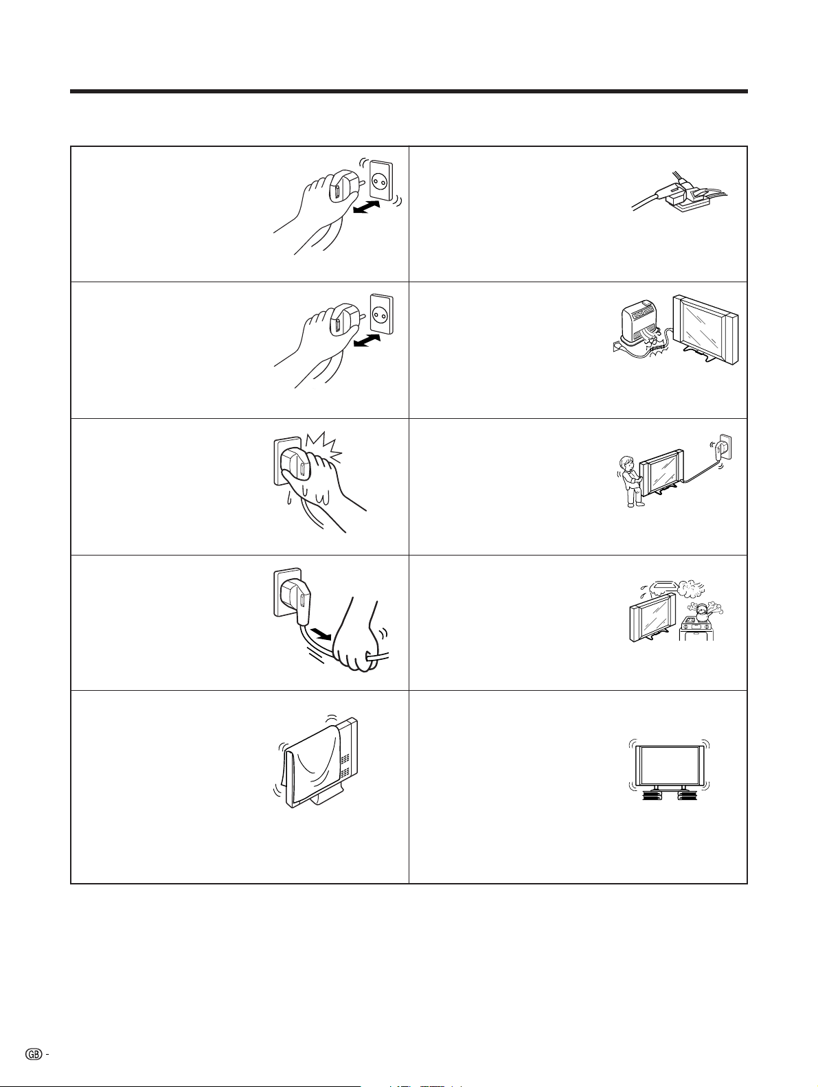
CAUTION: Please read all of these instructions before you operate your Plasma Display TV
and save these instructions for later use.
• Do not plug the power cord into an
outlet that is not firmly attached to
the wall, as this could cause
overheating and fire. Have an
authorized dealer or qualified
electrician replace the outlet.
• Plug the power cord into the wall
outlet securely. Failure to plug in
completely could generate
excessive heat, or if dust has
gathered, cause hazardous electric
shock and fire. Touching plug pins
could also cause electric shock.
• Never touch the power cord plug
with wet hands, as this could cause
hazardous electric shock.
• Never overload an outlet with too
many connections, as this could
cause hazardous electric shock
and fire.
• Heat sources—Keep the product
away from heat-generating sources
such as radiators, heaters, stoves
and amplifiers.
• When preparing to move the
product, detach all connected
cables. Failure to do so could
damage the power cord and cause
hazardous electric shock and fire.
• Never pull the power cord too
strongly with your hands, as this
could damage the cord and cause
hazardous electric shock and fire.
• Ventilation—The cabinet has
ventilation openings that should
never be blocked or covered.
Insufficient air circulation could
cause overheating and shorten
product life. Do not place on soft
surfaces (e.g. bed, sofa, rug), as
doing so could block ventilation
openings and cause internal parts
to overheat and catch fire.
• Avoid using the Plasma Display TV
in extremely humid or dusty
environments. Placing beside a
cooking appliance or humidifier
could cause hazardous electric
shock and fire.
• Stand—Do not place the product
on an unstable surface such as a
cart, stand, tripod or table, as this
could cause the product to fall over,
become damaged or injure
persons nearby. Take special care
when children are in the area. When
mounting the product on a wall, be
sure to follow the manufacture's
instructions. Use only the mounting
hardware recommended by the
manufacturer.
4
Page 7

Important User Guidance Information
In order to obtain maximum enjoyment from this SHARP PZ-50HV2E/PZ-50MR2E,PZ-43HV2E/PZ-43MR2E Plasma Display TV, please first
read this information carefully.
With the SHARP PZ-50HV2E/PZ-50MR2E,PZ-43HV2E/PZ-43MR2E, you can be assured of a high quality Plasma Display TV with long-life
and high reliability. To achieve images of exceptional quality, this SHARP Plasma Display TV incorporates state-of-the-art design and
construction, as well as very precise and highly advanced technology. On a total of nearly 3 million light cells, more than 99.999 percent
of the cells remain active.
Over the course of its lifetime, the luminosity of the SHARP PZ-50HV2E/PZ-50MR2E,PZ-43HV2E/PZ-43MR2E Plasma Display TV will
diminish very slowly, such as with all phosphor-based screens (for example, a traditional tube-type television). To enjoy beautiful and
bright images on your SHARP Plasma Display TV for a long time, please carefully read and follow the usage guidelines below:
Usage guidelines
All phosphor-based screens (including conventional tube-type televisions) can be affected by displaying static images for a prolonged
period. Plasma Display TV’s are no exception to this rule. After-image and permanent effects on the screen can be avoided by taking
some basic precautions. By following the recommendations listed below, you can ensure longer and satisfactory results from your Plasma
Display TV.
• Whenever possible, avoid frequently displaying the same image or virtually still moving pictures (e.g. video game images which have
static portions). After playing a game, or displaying a PC image or any still image, it is best to view a normal moving picture in the
“Panorama” or “Full” screen setting for more than 3 times the length of the previous still moving image.
• Do not display Teletext for a prolonged period of time.
• Avoid viewing the On Screen Display for extended periods, from a decoder, DVD player, VCR and all other components.
• Do not leave the same picture freeze-framed or paused continuously over a long period of time, when using the still picture mode
from a TV, VCR, DVD player or any other component.
• Images which have both very bright areas and very dark areas side by side should not be displayed for a prolonged period of time.
• When displaying a game, the “GAME” mode setting within “AV MODE” is strongly recommended. However, please limit its use to less
than 2 hours at a time.
• After using the Plasma Display TV, make sure to switch the display to “STAND BY” mode or to turn off the power.
Installation guidelines
The SHARP PZ-50HV2E/PZ-50MR2E,PZ-43HV2E/PZ-43MR2E Plasma Display TV incorporates a very thin design. To ensure safety, please
take the proper measures to mount or install the Plasma Display TV (Panel Unit), in order to prevent the unit from tipping over in the event
of vibration or accidental movement.
This product should be installed by using only parts and accessories designed by SHARP. Use of accessories other than the SHARP
stand or installation bracket may result in instability, and could cause injury. For custom installation, please consult the dealer where the
unit was purchased. To ensure correct installation, experienced and qualified experts must install the unit. SHARP will not be held responsible
for accident or damage caused by the use of parts and accessories manufactured by other companies.
To avoid malfunction and overheating, make sure that the vents on the main unit are not blocked when installing to ensure proper heat
emission:
• Distance the unit slightly from other equipment, walls, etc.
• Do not fit the unit inside narrow spaces where ventilation is poor.
• Do not cover with a cloth, etc.
• Clean the vents on the sides and rear of the unit to remove dust build-up, by using a vacuum cleaner set to its lowest suction setting.
Using the unit without proper ventilation may cause the internal temperature to rise, and could result in possible malfunction. When the
surrounding or internal temperature exceeds a certain degree, the display will automatically power off in order to cool the internal electronics
and prevent hazardous occurrences.
Any malfunction may occur due to: an inappropriate installation site, improper assembly, installation, mounting, or operation of this
product, modifications made to the product. However, SHARP cannot be held responsible for such accidents or malfunction.
A
• Typical effects and characteristics of a phosphor-based matrix display, e.g. permanent residual images upon the phosphor of the
panel, and the existence of a minute number of inactive light cells in the screen, are not covered by local warranties.
About the Plasma Display TV (Panel Unit)'s protection function
The brightness of this display will deteriorate slightly when an image with little movement such as a photograph or computer image is
continuously displayed. This is caused by the Plasma Display TV (Panel Unit)'s protection function which detects images with slight
movement and automatically adjusts brightness to protect the display, and is not a malfunction.
This function begins operating when the display detects no or little screen movement for a period of about three minutes.
L
Plasma Display TV (Panel Unit)'s sticking and after-image lag
• Displaying the same images such as still images for a long time may cause after-image lagging. This may occur in the following two
cases.
1. After-image lagging due to remaining electrical load
When image patterns with very high peak luminance are displayed for more than 1 minute, after-image lagging may occur due to the
remaining electric load. The after-images remaining on the screen will disappear when moving images are displayed. The time for the
after-images to disappear depends on the luminance of the still images and the time they had been displayed.
2. After-image (lag image) due to burning
Avoid displaying the same image on the Plasma Display TV (Panel Unit) continuously over a long period of time. If the same image is
displayed continuously for several hours, or for shorter periods of time over several days, a permanent after-image may remain on the
screen due to burning of the fluorescent materials. Such images may become less noticeable if moving images are later displayed, but
they will not disappear completely.
• The Power control function can be set to help prevent damage from screen burning. (See page 41.)
5
Page 8
Features
• Newly developed WIDE XGA Plasma Display TV (Panel Unit)
2,949,120 dots:PZ-50HV2E
2,359,296 dots:PZ-43HV2E
1
*
• Wide Viewing Angle
• NICAM/IGR Stereo Sound
• SRS and FOCUS Sound System*
1
• Multi-System TV Tuner
• Built-in TELETEXT Function (TOP/FLOF/FASTEXT)
• Dual screen function/Still Image function
• 12-Language On Screen Display
• 4 Video Input with 3 SCART terminals and PC (XGA) Input
• Component video input terminal
• Child Lock System
SRS and the symbol are trademarks of SRS Labs, Inc.
SRS technology is incorporated under license from SRS
Labs, Inc.
1
*
FOCUS and the symbol are trademarks of SRS Labs,
Inc. FOCUS technology is incorporated under license from
SRS Labs, Inc.
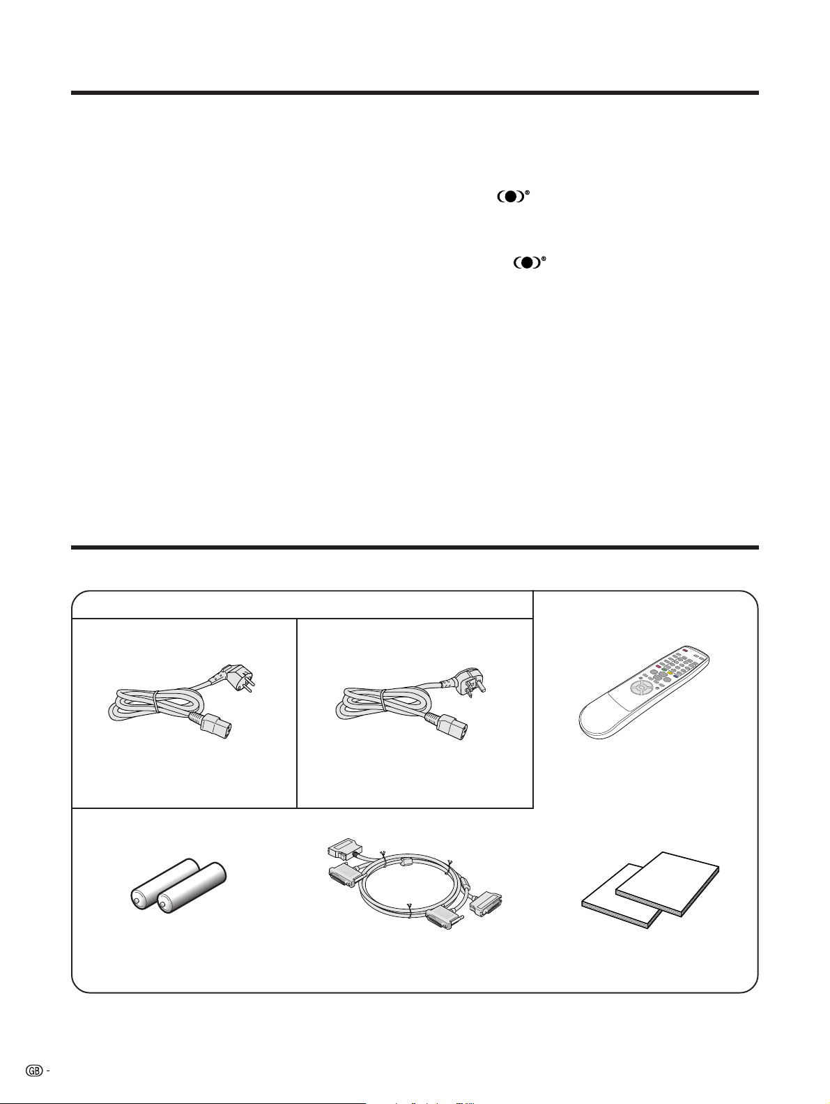
Supplied accessories
AVC System
Power cord
(For Europe, except U.K. and Eire) (For U.K. and Eire) Remote control unit
Two AA size batteries
(Alkaline battery)
A
• Always use the power cord supplied with the Plasma Display TV (Panel Unit) and the one supplied with the AVC System
for each respective unit.
6
System cable
Two operation manuals
Page 9
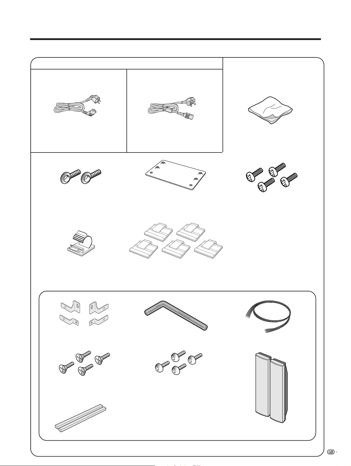
Supplied Accessories
Plasma Display TV (Panel Unit)
Power cord
(For Europe, except U. K. and Eire)
Two screws for preventing the
System from falling over
System cable clamp Five speaker cable clamps
Speaker unit
(For U. K. and Eire)
Set stand securing
bracket
Cleaning cloth
Four screws for set stand
securing bracket
Four speaker brackets
Four screws for speaker bracket Four screws for speaker bracket
Two spacers for speakers
Hexagon wrench
Two speaker cables
Two speakers
7
Page 10
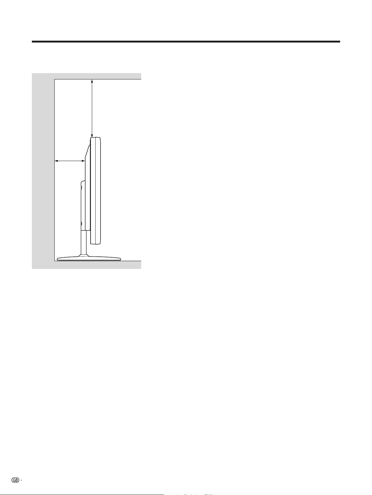
Preparation
Installing the Plasma Display TV (Panel Unit)
Locating
• Avoid direct sunlight and keep well ventilated.
Over
50 cm
Over
10 cm
• The length of the system cable used to connect the
Plasma Display TV (Panel Unit) and the AVC System
is about 3 m.
• This Plasma Display TV (Panel Unit) is heavy and
requires two or more persons to move it.
L
• Do not place anything on the AVC System. Otherwise, the
AVC System does not receive enough ventilation, and does
not operate properly.
A
• When installing, ensure that adequate ventilation space
is allowed at the top and rear of the product (as shown in
the diagram).
L
Operating Environment
Operating environment temperature and humidity: e0°C–
e40°C; less than 20–80%RH (cooling vents not blocked)
Avoid installing in the following locations:
• Under direct exposure to sunlight,
• Under strong artificial light,
• In high humidity,
• Poorly ventilated.
8
Page 11
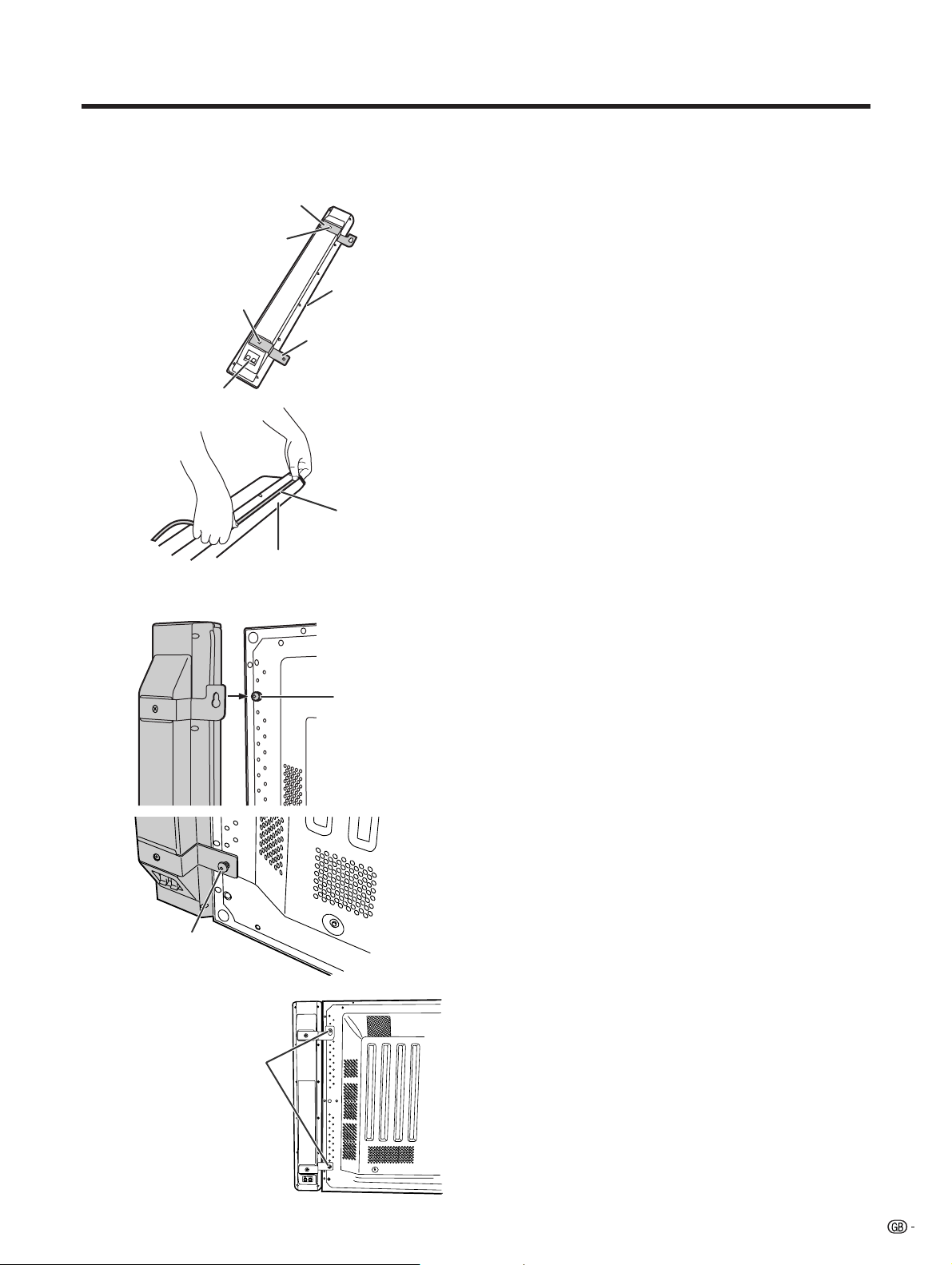
Preparation
a
Fixing the right speaker
Speaker bracket (upper part)
O headed screw
O headed screw
Speaker terminal
A
• Attach the spacer to the speaker along the grill
net.
Grill net
Spacer
Speaker bracket
(lower part)
Spacer
Fixing the speakers
1 Position the speaker brackets (upper and lower
parts) to the speaker, by firmly fastening the O
headed screws with a O screwdriver.
Speaker terminals are located on the lower part
of the speaker.
• The opening between the speaker parts and
Plasma Display TV (Panel Unit) can be filled with
the spacer. Attach the spacer to the speaker before
positioning the speaker brackets.
2 Loosely fasten the P headed screw to the
upper part of the Plasma Display TV (Panel
Unit) with the hexagon wrench. Hook the
speaker on the screw.
3 Loosely fasten the P headed screw to the lower
part of the Plasma Display TV (Panel Unit) with
the hexagon wrench.
4 Adjust the position so there is no unnecessary
opening between the speaker and the Plasma
Display TV (Panel Unit). Fasten firmly the screws
which loosely fastened in step 2 and 3 above.
Secure the other speaker by the same steps.
P headed screw
Fasten the P headed
screws with the hexagon
wrench.
P headed screw
L
• Do not apply force to the front grill net, nor put your fingers
into it.
• Using fittings other than the ones supplied, may cause
reduction in performance or malfunction of the speakers.
Use the supplied fittings to fix the speakers to the unit.
• Do not carry or move the display by holding the speakers.
Hold the bottom of the display when carrying.
A
• For details on the speaker cable connection and the cable
routing, see pages 11 and 12.
9
Page 12
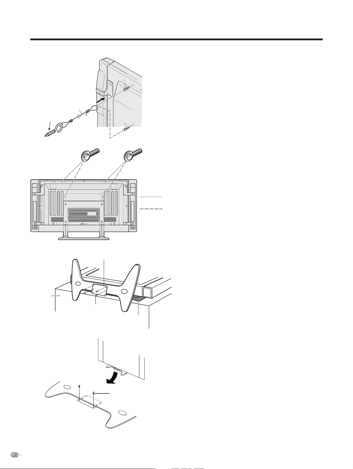
Preparation
Securing the Plasma Display TV (Panel
Unit) to the wall
Commercially
available
1
2
1
In the case of
PZ-50HV2E
In the case of
PZ-43HV2E
In the case of PZ-50HV2E
In the case of PZ-43HV2E
1 Fasten the two supplied eyelet screws.
2 Thread a suitable wire or rope through the eyelet
screws, and attach this to the wall at both sides.
Make sure that the Plasma Display TV (Panel
Unit) is firmly installed to the wall.
A
• The wire, rope and suitable fixings for these are available
commercially .
• The eyelet screws fit on different locations depending on
the Plasma Display TV (Panel Unit) screen size.
Desk
Securing bracket
2
(rear view)
4
1
Soft cloth
Fixing the Plasma Display TV (Panel
Unit) to a desk or floor
The unit can also be secured via the stand.
1 Cover a desk with a suitable soft cloth, and place
the Plasma Display TV (Panel Unit) on its side.
2 Attach the securing bracket as shown, using the
supplied screws.
3 Stand the unit upright and place in position.
4 Secure the unit to the desk or floor as shown in
the diagram, with suitable fixings (commercially
available).
10
Page 13
Preparation
Setting the system
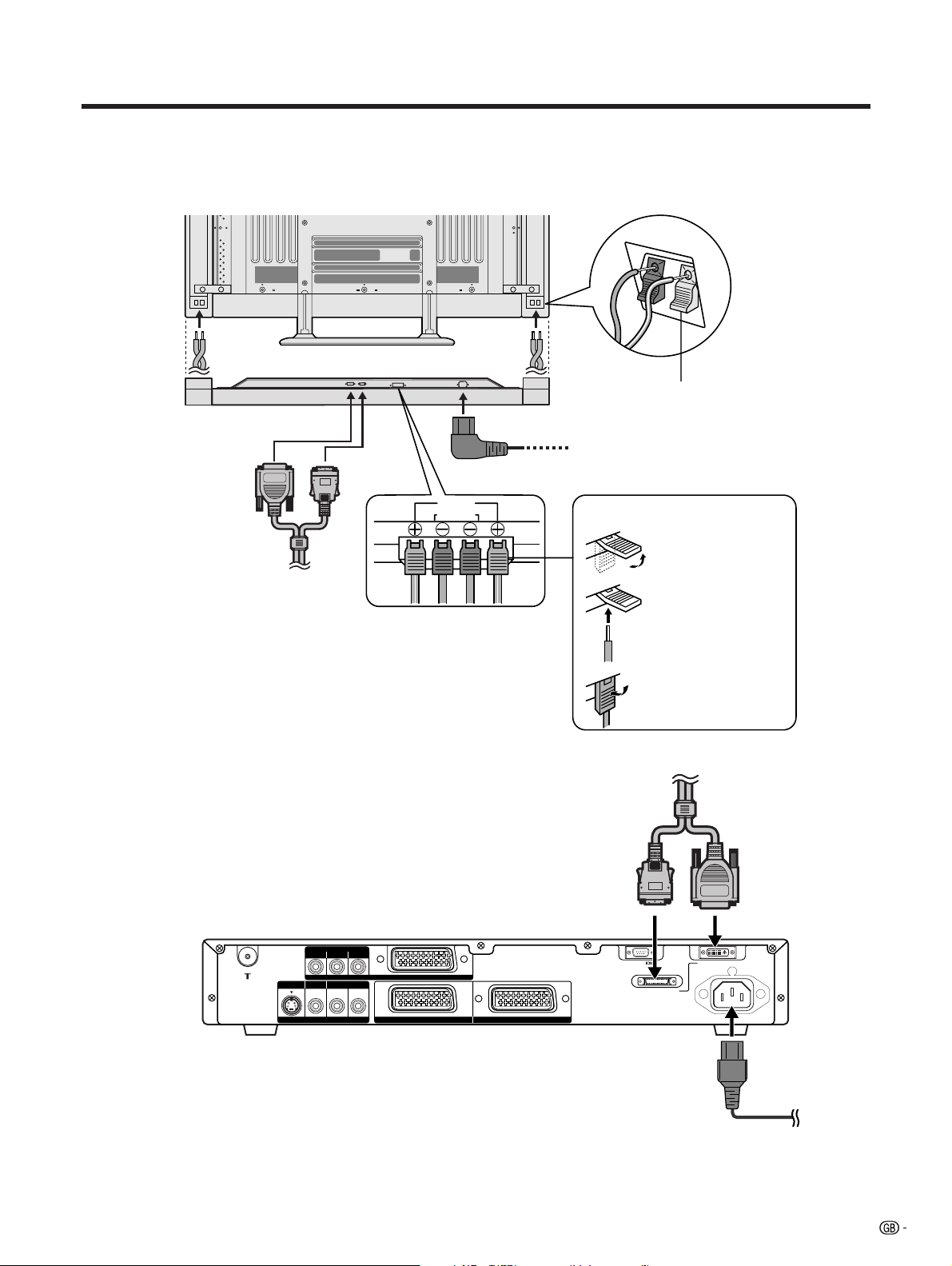
1. Connecting the system cable, the power cord and the speaker cables to the Plasma Display TV (Panel
Unit)
Plasma Display TV (Panel Unit) (rear view)
Black
Red
Speaker cable
Speaker cable
(bottom view)
(WHITE)
(GRAY)
Red
Black
System cable
Speaker cables
(GRAYeGRAY with white stripe)
A
• Two speaker cables of different lengths are supplied. As
shown in the diagram, connect the longer speaker cable
to the left speaker and the shorter to the right.
Power cord
Insert the speaker cable
2. Connecting the system cable and the power cord to the AVC System
As you apply pressure to this part,
insert the speaker cable. It is
important to match polarity when
connecting the speaker cables to the
terminals.
Lift up the snap clip.
Insert the wire into
the hole of the
connector.
Lower the snap clip
to grip the wire in
place.
System cable
(GRAY)
(WHITE)
AVC System (rear view)
COMPONENT
PB(CB)
PR(CR)Y
INPUT 3
AV OUTPUT
R - AUDIO - L
INPUT 2 INPUT 1
S-VIDEO VIDEO
L
• TO PREVENT RISK OF ELECTRIC SHOCK, DO NOT TOUCH UN-INSULATED PARTS OF ANY CABLES WITH THE
POWER CORD CONNECTED.
RS-232C DISPLAY OUTPUT-1
DISPLAY OUTPUT-2
AC INPUT
220–240V
Power cord
11
Page 14
Preparation
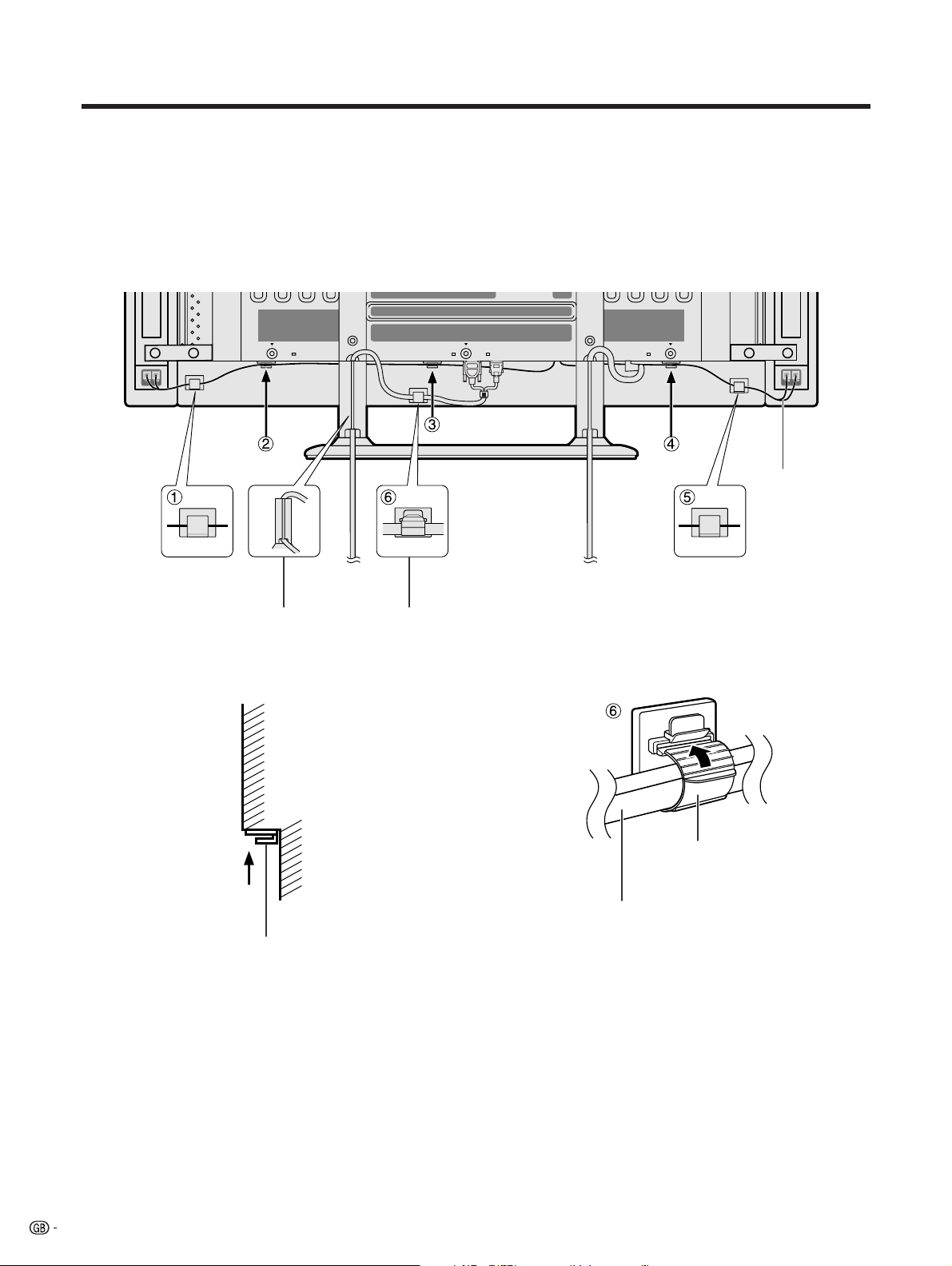
How to route cables
A system cable clamp and five speaker cable clamps are included with the system for cable management. Follow the
diagram below for correct cable management.
As viewed from the rear of the display.
Speaker cable
Power cord
Speaker cable clamp
System cable
Speaker cable clamp
Wedge the power cord and the
system cable into the groove on the
stand.
Stick the speaker cable clamps
(2 – 4) to the surface as shown.
System cable clamp
System cable clamp
System cable
12
Page 15
Preparation
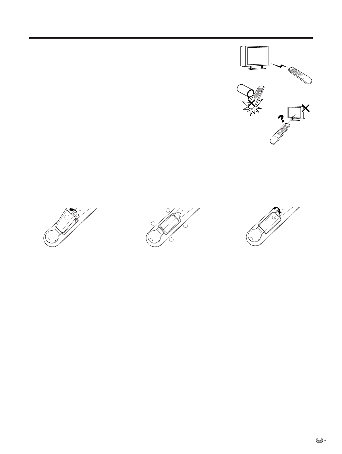
Using the remote control unit
Use the remote control unit by pointing it towards the remote sensor window.
Objects between the remote control unit and sensor window may prevent proper
operation.
Cautions regarding remote control unit
• Do not expose the remote control unit to shock.
In addition, do not expose the remote control unit to liquids, and do not place
in an area with high humidity.
• Do not install or place the remote control unit under direct sunlight.
The heat may cause deformation of the unit.
• The remote control unit may not work properly if the remote sensor window of
the Plasma Display TV (Panel Unit) is under direct sunlight or strong lighting.
In such case, change the angle of the lighting or Plasma Display TV, or operate
the remote control unit closer to the remote sensor window.
Inserting the batteries
If the remote control unit fails to operate Plasma Display TV functions, replace the batteries in the remote control
unit.
1 Open the battery cover. 2 Insert batteries (two AA size
3 Close the battery cover.
batteries, supplied with product).
+
_
• Place batteries with their terminals
corresponding to the (e) and (f)
indications in the battery compartment.
_
+
Cautions regarding batteries
Improper use of batteries can result in chemical leakage or explosion. Be sure to follow the instructions below.
• Do not use manganese batteries. When you replace the batteries, use alkaline ones.
• Place the batteries with their terminals corresponding to the (e) and (f) indications.
• Do not mix batteries of different types. Different types of batteries have different characteristics.
• Do not mix old and new batteries. Mixing old and new batteries can shorten the life of new batteries or cause
chemical leakage in old batteries.
• Remove batteries as soon as they have worn out. Chemicals that leak from batteries can cause a rash. If you
find any chemical leakage, wipe thoroughly with a cloth.
• The batteries supplied with this product may have a shorter life expectancy due to storage conditions.
• If you will not be using the remote control unit for an extended period of time, remove the batteries from it.
L
• WHEN DISPOSING OF USED BATTERIES, PLEASE COMPLY WITH GOVERNMENTAL REGULATIONS OR
ENVIRONMENTAL PUBLIC INSTRUCTION'S RULES THAT APPLY IN YOUR COUNTRY/AREA.
13
Page 16
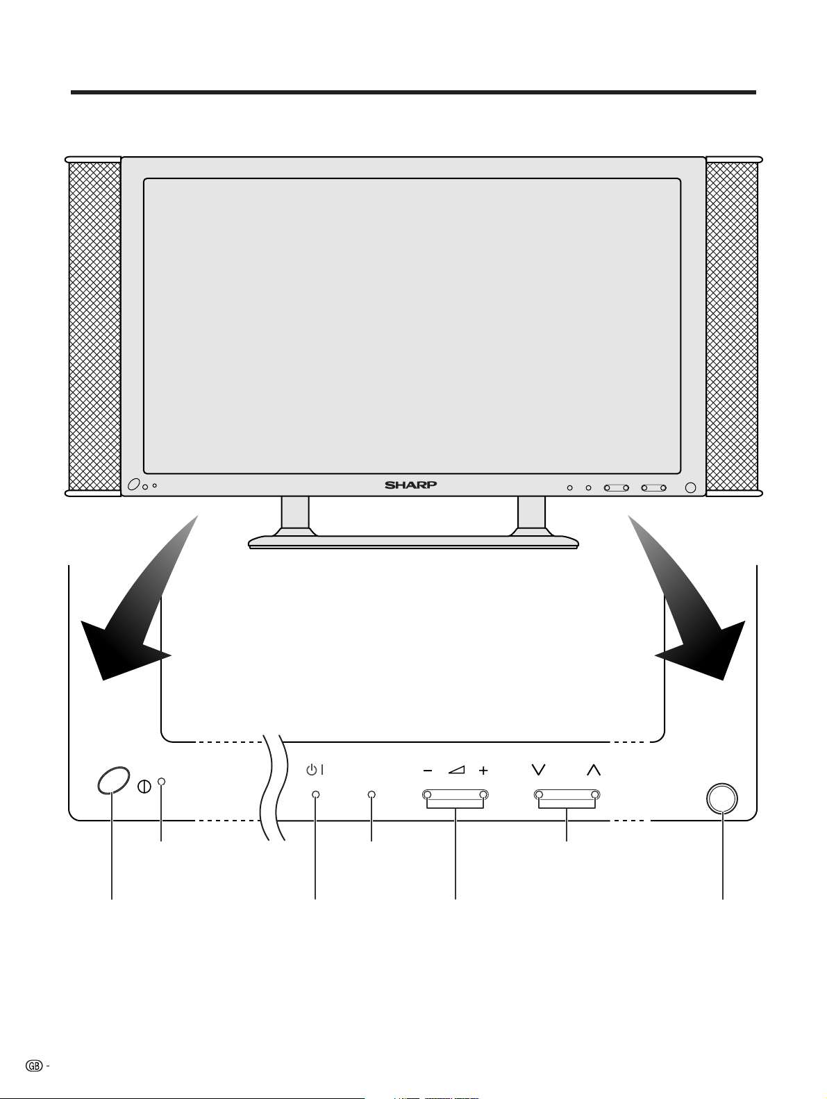
Part names
Plasma Display TV (Panel Unit)
MAIN POWER button
14
STANDBY/ON indicator
INPUT CH
INPUT button
STANDBY/ON button
VOLUME buttons
( il/k )
CHANNEL buttons
(CHs/r)
Remote control sensor
Page 17
Part names
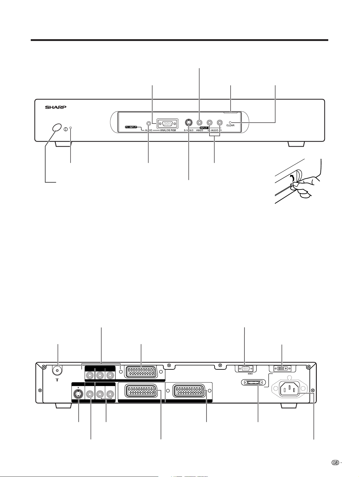
AVC System
Front view
PC INPUT terminal (ANALOG RGB)
STANDBY/ON indicator
PC INPUT terminal
INPUT 4 terminal (VIDEO)
Door knob
INPUT 4 terminals (AUDIO)
CLEAR button*
(AUDIO)
POWER button
INPUT 4 terminal (S-VIDEO)
(How to open the door)
* If the AVC System is switched on but it does not appear to be operating correctly, it may need resetting. In this
case press CLEAR on the front of the unit as shown in the diagram. Press CLEAR lightly with the end of a
ballpoint pen or other pointed object.
This will reset the System as shown below.
• AV MODE resets to STANDARD
• TV channel resets to channel 1
• Dual screen resets to normal
• Audio setting initialises
• SRS resets to Off
• Image position is initialised
A
• Pressing CLEAR will not work if the System is in standby mode (indicator lights red).
• Pressing CLEAR will not delete channel preset or password. See Page 58 for initialising factory preset settings when you
know your password. See Page 70 for initialising factory preset values when you have forgotten your password.
Rear view
INPUT 3 terminals
(Y, P
B(CB), PR(CR))
RS-232C terminal
ANTENNA INPUT terminal
S-VIDEO VIDEO
AV OUTPUT
AV OUTPUT terminal
(S-VIDEO)
AV OUTPUT terminal
(VIDEO)
INPUT 3 terminal (SCART)
COMPONENT
PB(CB)
PR(CR)Y
R - AUDIO - L
INPUT 3
AV OUTPUT terminals
(AUDIO)
INPUT 2 INPUT 1
INPUT 1 terminal
(SCART)
INPUT 2 terminal
(SCART)
DISPLAY OUTPUT-1 terminal
RS-232C DISPLAY OUTPUT-1
DISPLAY OUTPUT-2
AC INPUT
220–240V
DISPLAY OUTPUT-2 terminal
AC INPUT terminal
15
Page 18
Part names
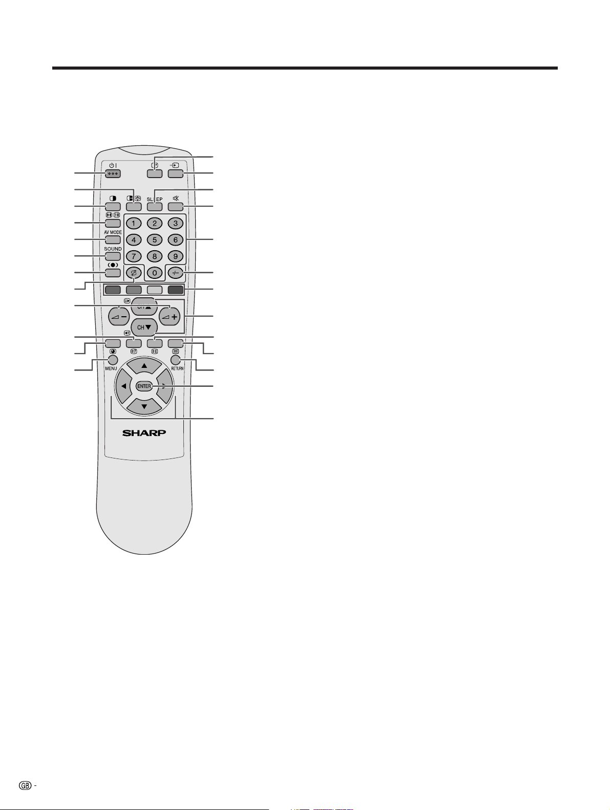
Remote control unit
1
2
3
4
5
6
7
8
9
10
11
12
A
• When using the remote control unit, point it
at the Plasma Display TV (Panel Unit).
* “TV”, “INPUT1”, “INPUT2”, “INPUT3”,
“INPUT4” and “PC” modes can each store
the WIDE mode setting separately.
The same for AV mode and volume.
16
13
14
15
16
17
18
19
20
21
22
23
24
25
1 B (STANDBY/ON)
To switch the power on and off.
2 du (FREEZE/HOLD for TELETEXT)
TV/External input mode: Change the still image mode.
TELETEXT mode: Freeze a multi-page on screen while other
pages are automatically updated. Press d again to return to the
normal image.
3 c (DUAL screen)
Set the dual picture mode. Press c again to return to normal view.
4 fv (WIDE MODE/ T/B/F)*
TV/External input mode: Change the wide image mode.
TELETEXT mode: Set the area of magnification. (full/upper half/
lower half)
5 AV MODE*
Select a video setting. AV MODE (STANDARD, DYNAMIC, MOVIE,
GAME, USER) PC MODE (STANDARD, USER)
6 SOUND
Select the sound multiplex mode.
7 h (SRS and FOCUS)
Select SRS and FOCUS Sound System.
8 A (FLASHBACK)
Press to return to the previous channel in normal viewing mode.
Press to return to the previous page in TELETEXT mode.
9 il/ik (VOLUME)*
Set the volume.
10 k (Reveal hidden for TELETEXT)
TELETEXT mode: Display hidden characters.
11 j (SUBPAGE for TELETEXT)
TELETEXT mode: Change the picture mode for sub-page selecting.
12 MENU
Display the Menu screen.
13 C (CHANNEL INFORMATION)
Display the channel information and time. (See page 63 for details
on the time display.)
14 b (INPUT SOURCE)
Select an input source. (TV, INPUT 1, INPUT 2, INPUT 3, INPUT 4,
PC)
15 SLEEP
Set the SLEEP TIMER.
16 e (MUTE)
Mute the sound.
17 0 – 9
TV/External input mode: Set the channel.
TELETEXT mode: Set the page.
18 o (Digit for channel select)
Change the digits of the selected TV channel.
19 Colour (RED/GREEN/YELLOW/BLUE)
TELETEXT mode: Select a page.
20 CHa/CHb(w/x )
TV/External input mode: Select the channel.
TELETEXT mode: Set the page.
21 l (TOP Overview for TELETEXT)
TELETEXT mode: Display an index page for CEEFAX/FLOF
information. TOP OVER VIEW for TOP programme.
22 m (TELETEXT)
Select the TELETEXT mode. (all TV image, all TEXT image, TV/TEXT
image)
23 RETURN
MENU mode: Return to the previous menu screen.
24 ENTER
Execute a command.
Return to the initial image position after moving with a/b/c/d.
25 a/b/c/d (Cursor)
Select a desired item on the setting screen.
Move the picture on the screen.
Page 19
Watching TV
Simple operations for watching a TV programme
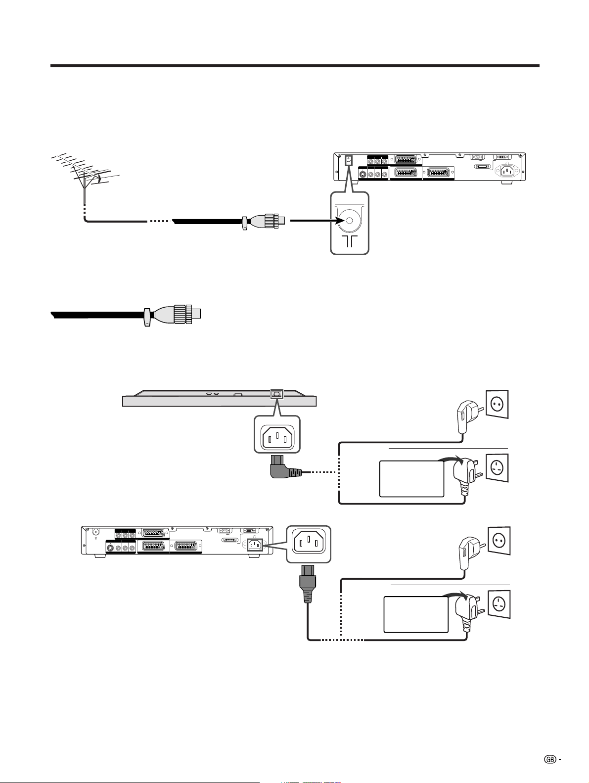
Basic connection
Connecting to an antenna
To enjoy a clearer picture, use an outdoor antenna. The following is a brief explanation of the types of connections
that are used for coaxial cable.
COMPONENT
PB(CB)
Standard DIN45325 plug (IEC169-2)
75-ohm coaxial cable (round
cable) (commercially available)
Antenna cables-commercially available
If your outdoor antenna uses a 75-ohm coaxial cable with a standard DIN45325
plug (IEC 169-2), plug it into the ANTENNA INPUT terminal at the rear of the
AVC System.
S-VIDEO VIDEO
AV OUTPUT
R - AUDIO - L
PR(CR)Y
INPUT 3
INPUT 2 INPUT 1
RS-232C DISPLAY OUTPUT-1
DISPLAY OUTPUT-2
AC INPUT
220–240V
Connecting to the power cord
Plasma Display TV (Panel Unit) (bottom view)
AVC System (rear view)
S-VIDEO VIDEO
AV OUTPUT
COMPONENT
PB(CB)
R - AUDIO - L
PR(CR)Y
INPUT 3
INPUT 2 INPUT 1
RS-232C DISPLAY OUTPUT-1
DISPLAY OUTPUT-2
AC INPUT
220–240V
AC INPUT
Europe, except U.K.
and Eire
U.K. and Eire
For U. K.
and Eire
Europe, except U.K.
and Eire
U.K. and Eire
For U. K.
and Eire
A
• Always turn off the main power of Plasma Display TV (Panel Unit) and AVC System when connecting the power cords.
• Disconnect the power cord from the power outlet, Plasma Display TV (Panel Unit) and AVC System when the System is
not going to be used long period of time.
17
Page 20
Watching TV
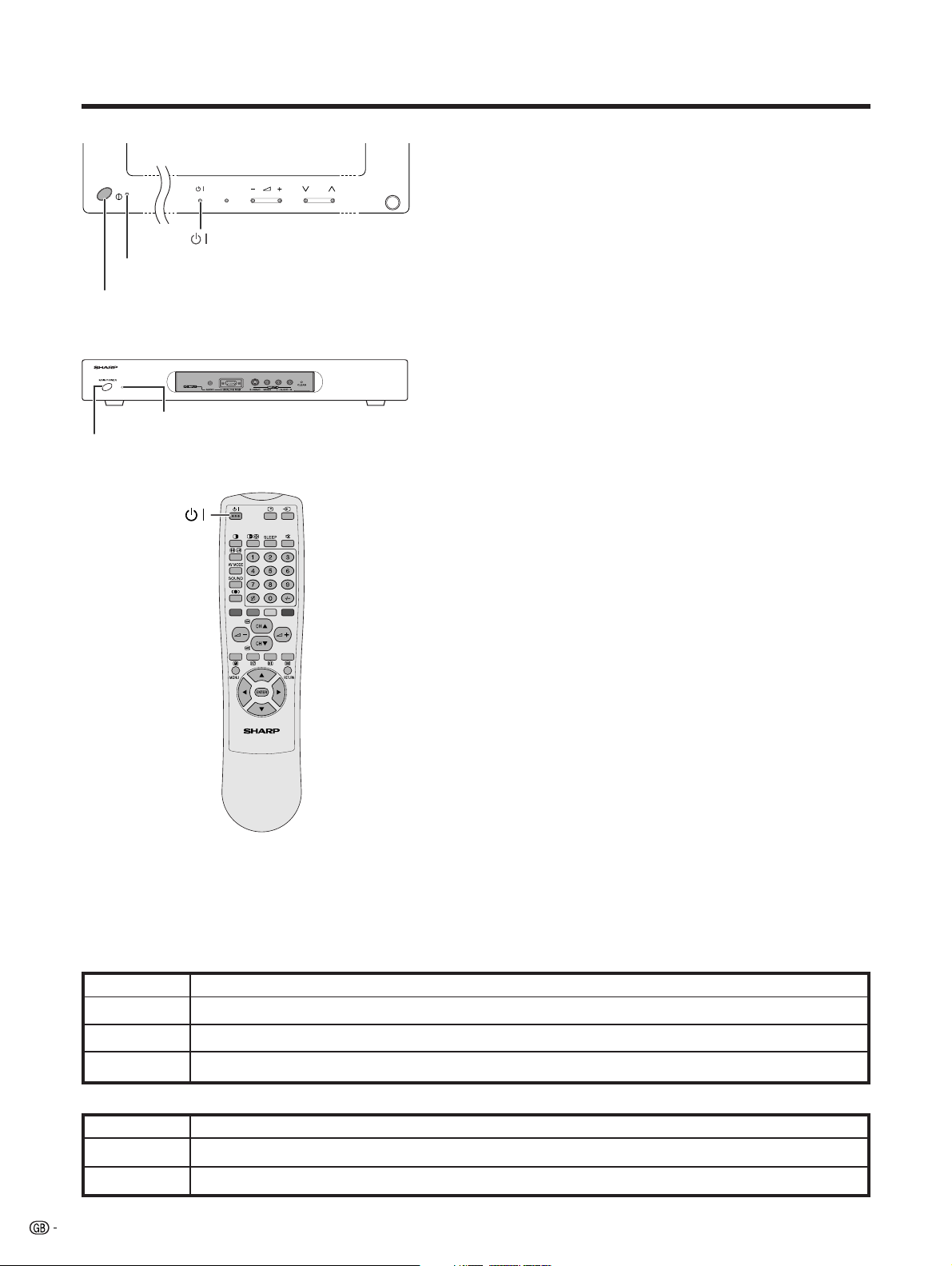
Plasma Display TV (Panel Unit)
INPUT CH
STANDBY/ON indicator
MAIN POWER
AVC System
STANDBY/ON indicator
POWER
Turning on the power
1 Press MAIN POWER on the Plasma Display TV (Panel Unit).
• The STANDBY/ON indicator on the Plasma Display TV (Panel
Unit) flashes red.
2 Press POWER on the AVC System.
• The System turns the power on.
• The STANDBY/ON indicator on the Plasma Display TV (Panel
Unit) lights up green and the one on the AVC System lights up
green.
• If the STANDBY/ON indicators still light up red, press B on
the remote control unit or the Plasma Display TV (Panel Unit)
to turn the System on.
When turning the AVC System on first
1 Press POWER on the AVC System.
• The STANDBY/ON indicator on the AVC System lights up red.
2 Press MAIN POWER on the Plasma Display TV (Panel Unit).
• The System turns the power on.
• The STANDBY/ON indicator on the Plasma Display TV (Panel
Unit) lights up green and the one on the AVC System lights up
green.
• If the STANDBY/ON indicators still light up red, press B on
the remote control unit or the Plasma Display TV (Panel Unit)
to turn the System on.
A
•“System” above means the Plasma Display TV (Panel Unit) and AVC
System.
• The initial auto installation starts when the System powers on for the first
time. If the System has been turned on before, the initial auto installation
will not be invoked. See page 28 to try auto installation from the Setup
menu.
Turning off the power
1 Press B on the remote control unit or the Plasma Display
TV (Panel Unit).
• The System enters standby mode and the image on the screen
disappears.
• Both STANDBY/ON indicators change from green to red.
2 Press POWER on the AVC System.
• The STANDBY/ON indicator on the AVC System turns off and
the one on the Plasma Display TV (Panel Unit) flashes red.
3 Press MAIN POWER on the Plasma Display TV (Panel Unit).
• The STANDBY/ON indicator on the Plasma Display TV (Panel
Unit) turns off after approximately 5 seconds.
A
• If you are not going to use this System for a long time, be sure to remove
the power cord from the power outlet.
Plasma Display TV (Panel Unit) status indicators
Off
Flashing red
Red
Green
Power off
AVC System does not turn on or its power cord is disconnected.
The Plasma Display TV is in standby mode.
The Plasma Display TV turns the power on.
AVC System status indicators
Off
Red
Green
18
Power off
Only the AVC System is in standby mode or the Plasma Display TV is in standby mode.
The Plasma Display TV turns the power on.
Page 21
Watching TV
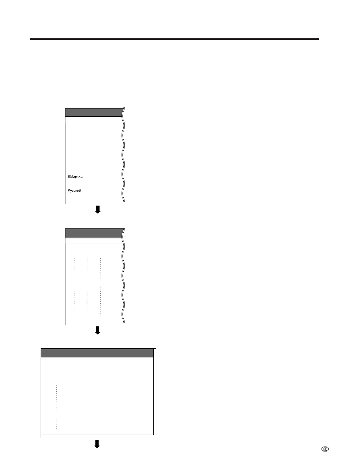
Initial auto installation
When the Plasma Display TV powers on for the first time after purchase, the initial auto installation is invoked.
You can automatically set language, country and channels in successive operations.
A
• See page 28 to try Auto installation from the setup menu.
Language menu
Auto Installation - Language
English
Deutsch
Français
Italiano
Español
Nederlands
Svenska
Português
Suomi
Türkçe
Country menu
Auto Installation - Country
Austria
Belgium
Denmark
A
B
DK
B/G
B/G
B/G
1. Setting the on-screen display language
1 Press a/b to select the desired language listed
on the screen.
2 Press ENTER to enter the setting.
2. Setting the country or area
1 Press a/b to select your country or area listed on
the screen.
2 Press ENTER to enter the setting.
• The programme auto search starts at the same time.
A
• Return to the Language menu by pressing RETURN.
Searching TV channels
Auto Installation - Setup “Auto”
1011142.25
010255.25
85.25
03 102.25
04
05
06
07
08
09
148.25
3. Automatic channel searching
Channel auto search makes the Plasma Display TV
look for all channels viewable in the set country or area.
A
• If no channel is found, “No programme found. Is antenna
connected properly?” displays. And the auto installation
is finished.
• If you want to try Auto installation again, see page 28.
19
Page 22
Watching TV
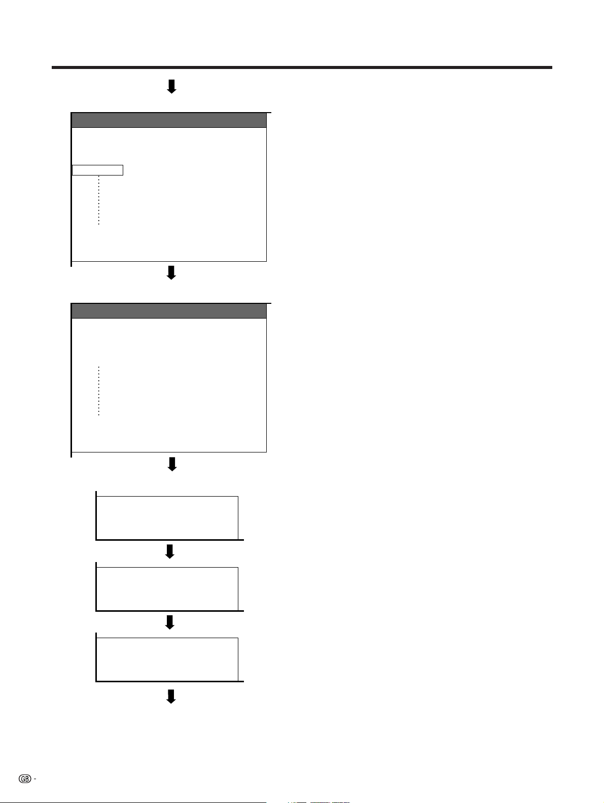
4. Automatic channel labelling
Labelling TV channels
Auto Installation - Setup “Auto”
10 142.25
0102SAT.1
PRO7
03 KABEL
04
05
06
07
130.25
08
136.25
09
11 148.25
12 155.25
Sorting TV channels
Auto Installation - Setup “Auto”
10 -----
0102SAT.1
PRO7
03 KABEL
04
05
06
07
08
09
11 -----
12 -----
VOX
QVC
After finding TV channels, the Plasma Display TV starts
naming each TV channel found.
A
• The system can only name channels where the channel
labeling information is provided. If channel information is
not provided, the system displays “-----” on screen.
• Cancel the setting by pressing RETURN and the System
automatically returns to the status before programme auto
search.
5. Automatic channel sorting
When channel auto labelling finishes, the Plasma
Display TV starts sorting the labelled channels.
A
• Cancel the setting by pressing RETURN. The system
automatically returns to the status before programme auto
search.
20
Preset download
Sending programme 10 settings.
Programme data sent successfully.
Auto Installation completed.
6. Preset download
When auto sorting finishes, the Plasma Display TV
automatically downloads and stores each sorted
channel.
• Each time a channel preset download finishes, “Sending
programme 10 settings.” displays. Once all presets have
downloaded, “Programme data sent successfully.”
displays.
• When a VCR is connected via INPUT 2, the System sends
all preset channel information to the VCR. See pages 30,
45 and 46.
Page 23

Watching TV
Channel display
SAT.1
1
PAL
B/G
Plasma Display TV (Panel Unit)
INPUT CH
CH /
0–9
A
/
When preset download finishes, your initial auto
installation is completed.
•“Auto Installation completed.” displays. After that, the
screen changes to the auto installation menu.
7. Watching TV
The setup menu disappears and you can watch the
programmes on channel 1.
Simple button operations for changing
channels
aa
Using CH
• Press CH
• Press CH
A
• CHs/r on the Plasma Display TV (Panel Unit) operates
the same as CH
Using FLASH BACK (A) on the
remote control unit
Press A to switch the currently tuned channel to the
previously tuned channel.
Press A again to switch back to the currently tuned
channel.
bb
a/
bon the remote control unit
aa
bb
aa
a to increase channel number.
aa
b b
b to decrease channel number.
b b
bb
aa
b/
aon the remote control unit.
bb
aa
MENU
Channel display
SAT.1
12
PAL
B/G
SAT.1
12
MONO
( Displays after 3 secs. )
Using 0 – 9 on the remote control unit
Select the channels directly by pressing buttons 0 to
9.
a
To select a 1-digit channel (e.g. channel 2):
• Press 2. If “2” is indicated and the picture does not
change, press o to switch over to the 1-digit select
mode and press 2 again.
To select a 2-digit channel (e.g. channel 12):
• Press o to set the 2-digit select mode. Press 1,
followed by 2.
A
• Complete this procedure within 3 seconds, otherwise the
selection will not be made on the 2-digit channel mode.
When viewing Teletext information
View a page directly which is 3-digit page number from
100 to 899 by pressing buttons 0 to 9. With Teletext,
you do not use o. See page 61.
21
Page 24

Watching TV
20
Plasma Display TV (Panel Unit)
INPUT CH
Simple button operation for changing
volume/sound
• To increase the volume, press i
• To decrease the volume, press i
A
•“TV”, “INPUT1”, “INPUT2”, “INPUT3”, “INPUT4” and “PC”
modes can each store volume adjustment values
separately.
Audio status
kk
k.
kk
ll
l.
ll
SOUND
Volume adjustment
20
Output device
Speaker
AV OUTPUT
* When “Audio Out” is set to “Variable”, the indicator on
the screen changes as shown below.
A
• See page 57 for details on the audio out function.
Variable sound
Constant as
specified
Audio out
VariableFixed
Mute
Variable sound
Using e on the remote control unit
e mutes the current sound output.
1 Press e.
•“e” has been displayed on the screen for 8 minutes,
and the sound is silenced.
22
Mute
A
• Within 8 minutes of pressing e, mute can be canceled
by using one of the two methods below.
• Pressing i
A can also cancel the mute.
• Changing channels can also cancel the mute.
• Mute will be canceled after 8 minutes have elapsed.
However, the system will not suddenly output a loud
sound as the volume level is set to 0 automatically.
ff
f/i
ff
ee
e, SOUND, CH
ee
aa
bb
a/CH
b, 0 – 9, b or
aa
bb
2 Within 8 minutes, Press e again to cancel the mute.
• Before 8 minutes, the volume level returns to the
previous setting.
• After 8 minutes, increase the volume level by pressing
ee
i
e.
ee
Page 25

Watching TV
Using h on the remote control unit
h produces SRS and FOCUS effect from the
speakers.
Each time you press h, the mode changes among
SRS, FOCUS, FOCUS e SRS and OFF.
SRS sound options
• SRS (Sound Retrieval System): Creates more a
natural sound retrieving the spatial information from
any stereo recording and restoring the original threedimensional sound field.
• FOCUS: Repositions a sound image from two
speakers to a more optimal listening position or
height without moving them.
• FOCUS e SRS: Produces both SRS and FOCUS
effects.
: OFF
: SRS
: FOCUS
: FOCUSSRS
• OFF: Outputs the normal sound.
23
Page 26

Watching TV
Using SOUND on the remote control unit
In the NICAM TV broadcasts
SOUND
NICAM broadcasts
Stereo mode
BBC2
NICAM
STEREO
BBC2
MONO
Monaural mode
BBC2
NICAM
MONO
BBC2
MONO
When receiving a stereo signal
Each time you press SOUND, the mode switches
between NICAM STEREO and MONO.
When receiving a bilingual signal
Each time you press SOUND, the mode switches
among NICAM CH A, NICAM CH B, NICAM CH AB
and MONO.
When receiving a monaural signal
Each time you press SOUND, the mode switches
between NICAM MONO and MONO.
Bilingual mode
99
99
99
99
BBC2
99
NICAM
CH A
BBC2
99
NICAM
CH B
BBC2
99
NICAM
CH AB
BBC2
99
MONO
In the TV mode of IGR TV broadcasts
When receiving a stereo signal
Each time you press SOUND, the mode switches
between STEREO and MONO.
When receiving a bilingual signal
Each time you press SOUND, the mode switches
among CH A, CH B and CH AB.
When receiving a monaural signal
When you press SOUND, “MONO” displays.
A
• When no signal is input, the sound mode will display
“MONO”.
•“BBC2” and “99” are tentative network name and channel.
IGR broadcasts
Stereo mode
Monaural mode
24
BBC2
STEREO
BBC2
MONO
BBC2
MONO
Bilingual mode
99
99
99
BBC2
99
CH A
BBC2
99
CH B
BBC2
99
CH AB
Page 27

Basic adjustment settings
AV Input mode menu items
List of AV menu items to help you with operations
Page 41
Power Control
Energy Save [Standard]
No signal off [Disable]
First MENU
MENU
Power Control
Picture
Audio
Setup
Option
No operation off
RETURN
Page 37–39
Picture
DYNAMIC
Contrast
Bright
Colour
Tint
Sharp
Advanced
Reset
RETURN
Page 40
Audio
DYNAMIC
Treble
Bass
Balance
Reset
RETURN
[+30]
[0]
[0]
[0]
[0]
[0]
[0]
[0]
[Disable]
0
–30
–30
–30
–7
–15
–15
Left
+40
+30
+30
+30
+7
Energy Save
No signal off
No operation off
Contrast
Bright
Colour
Tint
Sharp
Advanced
Reset
+15
+15
Right
MENU
MENU
MENU
Treble
Bass
Balance
Reset
Description
Save power by decreasing picture
brightness.
System automatically shuts down if
no video signal inputs for 15 minutes.
System automatically shuts down if
you do not operate the System for 3
hours.
Description
Adjusts the picture between light and
shade.
Adjusts picture brightness.
Adjusts colour intensity.
Adjusts skin colour to a more natural
tone for all colour system.
Adjusts picture sharpness.
Adjusts “Colour Temp”, “Film Mode”,
“Black”, “Monochrome”, “I/P Setting”.
All image adjustment settings return
to the factory preset values.
Description
Adjusts the treble weaker or stronger.
Adjusts the bass weaker or stronger.
Adjusts audio output between left
and right speakers.
All audio adjustment settings return
to the factory preset values.
Page 28–35, 58
Setup
Auto Installation
Programme Setup
Child Lock
RETURN
Page 36, 50, 52, 53, 56, 57
Option
Input Select
WSS
4:3 Mode
Position
Audio Out
Demo
Colour System
Language
RETURN
[On]
[4:3]
[Fixed]
[Off]
[Auto]
[English]
MENU
Auto Installation
Programme
Setup
Child Lock
MENU
Input Select
WSS
4:3 Mode
Position
Audio Out
Demo
Colour System
Language
Description
Runs auto installation again the same
as when the System powers on for
the first time after purchase.
Sets the channel preset.
Sets a password to restrict
operations.
Description
Select the kind of input signal of each input
source.
When wide screen signal bits are present in the
TELETEXT data, you can view information in
wide screen mode.
When you receive a 4:3 or 14:9 mode signal,
select “Normal” or “Panorama” display.
Adjusts the horizontal/vertical position of the
image displayed.
Select the type of audio output. You can adjust
volume for the main speaker or audio output.
Demonstration setting for storefront displays.
Select the colour system of an image current
input.
Select the on screen display language.
25
Page 28

Basic adjustment settings
PC Input mode menu items
List of PC menu items to help you with operations
Page 42
Power Control
Energy Save [Standard]
First MENU
MENU
Power Control
Picture
Audio
Option
Power Management
RETURN
Page 37
Picture
USER
Contrast
[+30]
Bright
[0]
Red
[0]
Green
[0]
Blue
[0]
Reset
RETURN
Page 40
Audio
USER
Treble
Bass
Balance
Reset
RETURN
[0]
[0]
[0]
[Off]
0
–30
–30
–30
–30
–15
–15
Left
+40
+30
+30
+30
+30
+15
+15
Right
MENU
Energy Save
Power
Management
MENU
Contrast
Bright
Red
Green
Blue
Reset
MENU
Treble
Bass
Balance
Reset
Description
Save power by decreasing picture
brightness.
System automatically shuts down if
you set the time. Select mode 1 or
mode 2.
Description
Adjusts the picture between light and
shade.
Adjusts picture brightness.
Adjusts red colour intensity.
Adjusts green colour intensity.
Adjusts blue colour intensity.
All image adjustment settings return
to the factory preset values.
Description
Adjusts the treble weaker or
stronger.
Adjusts the bass weaker or stronger.
Adjusts audio output between left
and right speakers.
All audio adjustment settings return
to the factory preset values.
26
Page 51, 57
Option
Auto Sync.
Fine Sync.
Audio Out
RETURN
[Fixed]
MENU
Auto Sync.
Fine Sync.
Audio Out
Description
Provides a clear input image.
Adjusts image “H-Pos.”, “V-Pos.”,
“Clock”, “Phase”.
Select the type of audio output. You can adjust
volume for the main speaker or audio output.
Page 29

Basic adjustment settings
Moving the picture on the screen
You can move the picture around on the screen.
ENTER
///
Press a/b/c/d to move an image on the screen to
the desired position. Press ENTER to return to the initial
image position.
A
• While pressing a/b /c/d, an on-screen image,
“Adjusting Position” displays to the desired position.
• This setting cannot be stored. Once the System shuts
down or enters standby mode, the setting is erased. To
move the picture around the screen again, you must
perform the above procedure again.
• The image position setting using the steps on page 50
can be stored. Select either according to your objectives.
•“TV”, “INPUT1”, “INPUT2”, “INPUT3”, “INPUT4” and “PC”
modes can each adjust the image position setting on this
page. The same for WIDE modes.
• An on-screen image from a PC source cannot be moved
around.
• Even when the image fills the screen, its position can be
adjusted with this function.
27
Page 30

Basic adjustment settings
Auto installation
You can run auto installation again, even after setting up the preset channels.
Password menu
MENU
Setup
Password
0–9
A
• This menu displays when setting the
password for the child lock. See
page 58.
Setup menu
MENU
ENTER
/
MENU
Setup
Auto Installation
Programme Setup
Child Lock
RETURN
Language menu
Auto Installation - Language
English
Deutsch
Français
Italiano
Español
Nederlands
Svenska
Português
- ---
Language setting
Select from among 12 languages: English, German,
French, Italian, Spanish, Dutch, Swedish, Portuguese,
Greek, Finnish, Russian and Turkish.
1 Press MENU.
2 Press a/b to select “Setup”, and then press
ENTER.
• Password setting menu displays only when the
password for the child lock is set. See page 58.
• Setup menu displays when the password for the child
lock is not set. Skip the step 3.
3 Enter your 4-digit password with 0 – 9 to temporarily
lift the child lock when you set it.
• See page 58 for details on temporarily lifting the child
lock.
4 Press a/b to select “Auto Installation”, and then
press ENTER.
• Language menu displays.
5 Press a/b to select the desired language listed
on the screen, and then press ENTER.
• Country menu displays.
28
Suomi
Türkçe
Country menu
Auto Installation - Country
Austria
Belgium
Denmark
A
B
DK
B/G
B/G
B/G
Country setting
After setting the language, to use the Plasma Display
TV you have to select the country, which sets the colour
system for viewable TV channels.
Setting screen displays.
1 Press a/b to select your country or area listed on
the screen.
2 Press ENTER.
• The country is set and the programme auto search
starts at the same time.
A
• Return to the language menu by pressing RETURN.
Page 31

Basic adjustment settings
Searching TV programmes
Auto Installation - Programme Setup “Auto”
010255.25
85.25
03 102.25
Labelling TV channels
Auto Installation - Programme Setup “Auto”
10 222.25
0102SAT.1
85.25
03 102.25
112.25
04
125.25
05
175.25
06
199.25
07
210.25
08
216.00
09
Programme auto search
After setting the country, perform the procedure below
to search TV channels.
A
• Cancel the setting by pressing RETURN and the System
automatically returns the status before programme auto
search.
• If no channels were found, you should check your
antenna connection, and try auto installation again
because it is finished. (See page 17)
• If the country setting has failed, TV channels may not
be found.
Auto labelling
After finding new TV channels, each network name
are searched and displays.
A
• Cancel the setting by pressing RETURN and the System
automatically returns the status before programme auto
search.
Reading broadcasting station names.
29
Page 32

Basic adjustment settings
Auto sorting
Sorting TV channels
Auto Installation - Programme Setup “Auto”
10 -----
0102SAT.1
PRO7
03 KABEL
04
05
06
07
08
-----
09
Sorting channels.
Automatically sorts TV channels.
A
• Cancel the setting by pressing RETURN and the System
automatically returns to the status before programme auto
search.
• Don’t shut down the System until “Sorting channels.”
displays.
• If the country setting has failed, TV channels may not
be sorted properly.
Preset download
Sending programme 10 settings.
Programme data sent successfully.
Auto Installation completed.
Preset download
When auto sorting finishes, the channels are
automatically stored in memory.
• The “10” in “Sending programme 10 settings” indicates
10 channels.
•“Sending programme 10 settings.” displays during each
channel preset download. Once all presets have
downloaded, “Programme data sent successfully.”
displays.
• The System can only send preset channel information to
a VCR when that device is connected via the INPUT 2
terminal.
30
Page 33

Basic adjustment settings
Programme setup
You can run the auto installation procedure again at any time, by accessing the Setup menu, then Programme
Setup. Channels can be turned automatically or manually.
MENU
ENTER
/
Programme Setup “Manual” menu
Programme Setup “Manual”
10
01
02
03
04
05
06
07
08
09
SAT.1
PRO7
KABEL
11
12
13
14
15
16
17
18
19
20
21
22
23
24
25
26
27
28
29
MENU
Setup
Auto Installation
Programme Setup
Child Lock
RETURN
Auto search
You can also automatically search and download TV
channels by performing the procedure below. This is
the same function as from programme auto search to
preset download in auto installation on pages 29 to
30.
1 Press MENU.
2 Press a/b to select “Setup”, and then press
ENTER.
MENU
Setup
Programme Setup
Auto Search
Manual Adjust
Sort
RETURN
3 Press a/b to select “Programme Setup”, and then
press ENTER.
4 Press a/b to select “Auto Search”, and then press
ENTER.
• Programme auto search starts as shown below.
1 Programme auto search
2 Auto labelling
3 Auto sorting
4 Preset download
A
• Return to the previous menu by pressing RETURN before
programme auto search starts.
• See pages 29 to 30 for the details on the programme auto
search.
MENU
Setup
Programme Setup
Auto Search
Manual Adjust
Sort
RETURN
Manual setting for each channel
You can set some channel items manually. They are
Fine (TV frequency), Colour sys., Sound sys., Label
(Network name), Skip, Decoder and Lock (Child Lock).
1 Press MENU.
2 Press a/b to select “Setup”, and then press
ENTER.
3 Press a/b to select “Programme Setup”, and then
30
31
32
33
34
35
36
37
38
39
40
41
42
43
44
45
46
47
48
49
Fine
Colour sys.
Sound sys.
Label
Skip
Decoder
Lock
[NEXT]
179.75MHz
AUTO
B/G
SAT.1
Off
Off
Off
press ENTER.
4 Press a/b to select “Manual Adjust”, and then
press ENTER.
• Programme Setup “Manual” menu displays.
A
• Return to the previous menu by pressing RETURN.
• Exit the menu by pressing MENU.
• When you exit Programme Setup “Manual” menu, preset
download automatically runs if you change information
on that menu.
Please select channel to be edited.
31
Page 34

Basic adjustment settings
Programme Setup “Manual” menu
Programme Setup “Manual”
10
11
01
SAT.1
12
02
PRO7
13
03
KABEL
14
04
15
05
16
06
17
07
18
08
19
09
Please select channel to be edited.
20
21
22
23
24
25
26
27
28
29
30
31
32
33
34
35
36
37
38
39
40
41
42
43
44
45
46
47
48
49
[NEXT]
Fine
Colour sys.
Sound sys.
Label
Skip
Decoder
Lock
179.75MHz
AUTO
B/G
SAT.1
Off
Off
Off
Additional channels entry
On Programme Setup “Manual” menu
1 Press a/b/c/d to select a channel number
(highlighted blue), and then press ENTER.
• Listed channels are black for “Skip” set to “Off” or blue
for “Skip” set to “On” or no channel.
• The selected channel information displays.
2 Press a/b to select “Skip”, and then press ENTER.
• Skip menu displays.
3 Press a/b to set “Skip” to “Off”, and then press
ENTER.
• Channels with “Skip” set to “On” are skipped even if
you select them by using CHa/CHb while watching
the image from the TV.
A
• Return to the previous menu by pressing RETURN.
• Exit the menu by pressing MENU.
Fine tuning menu
Programme Setup “Manual”
01
02
PRO7
03 KABEL
Programme Setup “Manual”
01
02
PRO7
03 KABEL
Colour system menu
Programme Setup “Manual”
01
SAT.1
02
PRO7 PAL
Fine
Fine
Colour sys.
AUTO
PAL-60
SECAM
NTSC 4.43
Fine tuning
On Programme Setup “Manual” menu
196.25 MHzSAT.1
1 Press a/b/c/d to select the channel you want to
edit, and then press ENTER.
• The selected channel information displays.
2 Press a/b to select “Fine”, and then press ENTER.
• Fine tuning bar displays.
3 Press c/d to adjust the frequency, and then press
ENTER.
• Adjust while checking the background picture as a
1 9 6.2 5MHzSAT.1
reference.
• Instead of the above, you can also set by directly
entering the frequency number of the channel with 0 –
9.
a
• 179.75 MHz: Press 1 s 7 s 9 s 7 s 5.
• 49.25 MHz: Press 4 s 9 s 2 s 5 s ENTER.
A
• Return to the previous menu by pressing RETURN.
• Exit the menu by pressing MENU.
Colour system
On Programme Setup “Manual” menu
1 Press a/b/c/d to select the channel you want to
edit, and then press ENTER.
• The selected channel information displays.
2 Press a/b to select “Colour sys.”, and then press
ENTER.
• Receivable colour systems are listed.
3 Press a/b to select the optimum colour system,
and then press ENTER.
32
A
• Return to the previous menu by pressing RETURN.
• Exit the menu by pressing MENU.
Page 35

Basic adjustment settings
Sound menu
Programme Setup “Manual”
01
SAT.1
02
PRO7 D/K
Sound sys.
B/G
I
L
L’
Sound system (Broadcasting system)
On Programme Setup “Manual” menu
1 Press a/b/c/d to select the channel you want to
edit, and then press ENTER.
• The selected channel information displays.
2 Press a/b to select “Sound sys.”, and then press
ENTER.
• Receivable sound systems (Broadcasting systems) are
listed.
3 Press a/b to select the optimum sound system,
and then press ENTER.
A
• If you adjust this setting, please check the colour system
information on page 32.
• Return to the previous menu by pressing RETURN.
• Exit the menu by pressing MENU.
Labelling menu
Programme Setup “Manual”
01
SAT.1
02
PRO7
03 KABEL
Programme Setup “Manual”
01
02
PRO7
03 KABEL
Skip menu
Label
KABEL
A
H
O
V
2
9+–
Skip
OffSAT.1
On
Labelling channels
When a TV channel sends its Network Name, the auto
installation detects the information and assigns a name
to it. However, you can change individual channel
G
B
C
D
E
F
CLEAR
I
J
K
L
M
N
P
Q
R
S
T
U
W
X
Y
Z
0
1
NEXT
3
4
5
6
7
8
BACK
END.
names.
On Programme Setup “Manual” menu
1 Press a/b/c/d to select the channel you want to
edit, and then press ENTER.
• The selected channel information displays.
2 Press a/b to select “Label”, and then press
ENTER.
• Alphabet and numbers are listed.
3 Press a/b/c/d to select each character of the
new name for the channel, and then press ENTER.
4 Repeat the above until the name is fully spelt out.
• The name can be 5 characters or less.
A
• Return to the previous menu by pressing RETURN.
• Exit the menu by pressing MENU.
Skipping channels
Channels with “Skip” set to “On” are passed over when
using CHa/CHb even if selected while watching the
image from the TV.
On Programme Setup “Manual” menu
1 Press a/b/c/d to select the channel you want to
edit, and then press ENTER.
• The selected channel information displays.
2 Press a/b to select “Skip”, and then press ENTER.
• Skip menu displays.
3 Press a/b to set “Skip” to “On”, and then press
ENTER.
A
• Return to the previous menu by pressing RETURN.
• Exit the menu by pressing MENU.
33
Page 36

Basic adjustment settings
MENU
ENTER
///
Setting the decoder
When connecting a decoder to the unit, you need
assign the terminal input.
On Programme Setup “Manual” menu
1 Press a/b/c/d to select the channel you want to
edit, and then press ENTER.
• The selected channel information displays.
2 Press a/b to select “Decoder”, and then press
ENTER.
• Terminal inputs information displays.
3 Press a/b to select an INPUT terminal, and then
press ENTER.
A
•“Off” is factory preset value.
• Return to the previous menu by pressing RETURN.
• Exit the menu by pressing MENU.
Decoder menu
Programme Setup “Manual”
01
SAT.1
02
PRO7
03 KABEL
Programme Setup “Manual”
01
02
PRO7
03 KABEL
Lock menu
Decoder
Off
INPUT1
INPUT2
INPUT3
Lock
OffSAT.1
On
Setting the child lock
You can block the viewing of any channel.
On Programme Setup “Manual” menu
1 Press a/b/c/d to select the channel you want to
edit, and then press ENTER.
• The selected channel information displays.
2 Press a/b to select “Lock”, and then press
ENTER.
• Child lock menu displays.
3 Press a/b to set “Lock” to “On”, and then press
ENTER.
A
• Even when this function is switched “On”, it will not work if
a password has not been set. See page 58 for details on
password setting.
• When “Lock” is set to “On” for a channel, “CHILD LOCK
HAS BEEN ACTIVATED.” displays , and the image and
sound of the channel is blocked.
• When pressing ENTER while “CHILD LOCK HAS BEEN
ACTIVATED.” displays, password input menu will display.
Inputting the correct password lifts the child lock
temporarily until the power is turned off.
• Return to the previous menu by pressing RETURN.
• Exit the menu by pressing MENU.
34
Page 37

Basic adjustment settings
MENU
Programme Setup
Auto Search
Manual Adjust
MENU
Setup
Sort
RETURN
Sort
Channel positions can be sorted freely.
1 Press MENU.
2 Press a/b to select “Setup”, and then press
ENTER.
3 Press a/b to select “Programme Setup”, and then
press ENTER.
4 Press a/b to select “Sort”, and then press ENTER.
• The channels are listed. Black ones are set “Skip” to
“Off” and blue are set “Skip” to “On”.
Sort menus
Programme Setup “Sort”
0102SAT.1
03 KABEL
04
05
06
07
08
09
Please select channel to replace.
10 -----
PRO7
VOX
ENTER
///
Press b.
Programme Setup “Sort”
0102PRO7
03 KABEL
04
05
06
07
08
09
10 -----
SAT.1
VOX
5 Press a/b/c/d to select the channel you want to
move, and then press ENTER.
6 Move it to the desired position by pressing a/b/
c/d, and then press ENTER.
7 Repeat the steps 5 and 6 until all desired channels
have sorted.
A
• Return to the previous menu by pressing RETURN.
• Exit the menu by pressing MENU.
Press b.
Sorting channels.
Programme Setup “Sort”
0102PRO7
03 SAT.1
04
05
06
07
08
09
10 -----
KABEL
VOX
35
Page 38

Basic adjustment settings
Language Setting for On-screen Display
You can also select a language from option menu. Select from among 12 languages: English, German, French,
Italian, Spanish, Dutch, Swedish, Portuguese, Greek, Finnish, Russian and Turkish.
MENU
ENTER
/
MENU
Option
Input Select
WSS
4:3 Mode
Position
Audio Out
Demo
Colour System
Language
RETURN
MENU
Option
Language
English
Deutsch
Français
Italiano
Español
Nederlands
Svenska
Português
[On]
[4:3]
[Fixed]
[Off]
[Auto]
[English]
1 Press MENU.
2 Press a/b to select “Option”, and then press
ENTER.
• Option menu displays.
3 Press a/b to select “Language”, and then press
ENTER.
• Language menu displays.
4 Press a/b to select the desired language listed
on the screen, and then press ENTER.
5 Press MENU to exit the menu.
A
• Return to the previous menu by pressing RETURN.
36
Suomi
Türkçe
Page 39

Basic adjustment settings
Picture adjustments
Adjust the picture to your preference with the following picture settings.
1 Press MENU.
2 Press a/b to select “Picture”, and then press
ENTER.
AV MODE
• Picture menu displays.
3 Press a/b to select a specific adjustment item.
4 Press c/d to adjust the item to your desired
position.
MENU
ENTER
///
5 Press MENU to exit the menu.
A
• When all adjustments set to factory preset values,
1 Press a/b to select “Reset”, and then press ENTER.
2 Press a/b to select “Yes”, and then press ENTER.
• Return to the previous menu by pressing RETURN.
• If you select “STANDARD” with AV MODE on the
remote control unit, these items will display in gray
and not be selectable. See page 53.
Adjustments items for AV source
MENU
DYNAMIC
Contrast
Bright
Colour
Tint
Sharp
Advanced
Reset
RETURN
Selected item
Contrast
Bright
Colour
Picture
[+30]
0
[0]
–30
[0]
–30
[0]
–30
[0]
–7
cbutton
For less contrast
For less brightness
For less colour
intensity
AV mode
+40
+30
+30
+30
+7
dbutton
For more contrast
For more brightness
For more colour
intensity
Adjustments items for PC source
MENU
USER
Contrast
Bright
Red
Green
Blue
Reset
RETURN
Selected item
Contrast
Bright
Red
Picture
[+30]
0
[0]
–30
[0]
–30
[0]
–30
[0]
–30
cbutton
For less contrast
For less brightness
For weaker red
AV mode
+40
+30
+30
+30
+30
dbutton
For more contrast
For more brightness
For stronger red
Tint
Sharp
Skin tones become
purplish
For less sharpness
Skin tones become
greenish
For more sharpness
A
• Select “Advanced” and then press ENTER to set “Colour
Temp”, “Film Mode”, “Black”, “Monochrome” or "I/P
setting". See pages 38 and 39.
Green
Blue
For weaker green
For weaker blue
For stronger green
For stronger blue
37
Page 40

Basic adjustment settings
AV MODE
MENU
DYNAMIC
MENU
Advanced
ENTER
/
Picture
Colour Temp [High]
High
Mid-High
Mid
Mid-Low
Low
Colour temperature
Adjust the colour temperature to give the best white
image.
1 Press MENU.
2 Press a/b to select “Picture”, and then press
ENTER.
3 Press a/b to select “Advanced”, and then press
ENTER.
4 Press a/b to select “Colour Temp”, and then press
ENTER.
5 Press a/b to select the desired level, and then
press ENTER.
6 Press MENU to exit the menu.
A
• Return to the previous menu by pressing RETURN.
• If you select “STANDARD” with AV MODE on the remote
control unit, this item will display in gray and not be
selectable. See page 53.
MENU
Picture
DYNAMIC
Advanced
Film Mode [On]
Off
On
Selected item
High
Mid-High
Mid
Mid-Low
Low
Description
White with Bluish tone
White with Reddish tone
Film mode
Automatically detects a film-based source (originally
encoded at 24 frames/second), analyses it then
recreates each still film frame for high-definition picture
quality.
1 Press MENU.
2 Press a/b to select “Picture”, and then press
ENTER.
3 Press a/b to select “Advanced”, and then press
ENTER.
4 Press a/b to select “Film Mode”, and then press
ENTER.
5 Press a/b to select “On”, and then press ENTER.
38
6 Press MENU to exit the menu.
A
• Return to the previous menu by pressing RETURN.
• If you select “STANDARD” with AV MODE on the remote
control unit, or input sources with vertical frequency
50 Hz (e.g. PAL, SECAM etc.), this item will display in
gray and not be selectable. See page 53.
Page 41

Basic adjustment settings
AV MODE
MENU
MENU
ENTER
/
Picture
DYNAMIC
Advanced
Black [High]
Off
High
Low
Black
This allows you to select a level for automatic
adjustment of a black areas of the image to suit viewing
conditions.
1 Press MENU.
2 Press a/b to select “Picture”, and then press
ENTER.
3 Press a/b to select “Advanced”, and then press
ENTER.
4 Press a/b to select “Black”, and then press
ENTER.
5 Press a/b to select the desired level, and then
press ENTER.
6 Press MENU to exit the menu.
A
• Return to the previous menu by pressing RETURN.
• If you select “STANDARD” with AV MODE on the remote
control unit, this item will display in gray and not be
selectable. See page 53.
MENU
Interlace
Progressive
MENU
Picture
DYNAMIC
Advanced
Monochrome [On]
Off
On
MENU
Picture
DYNAMIC
Advanced
I/P Setting [Progressive]
Interlace
Progressive
Description
Method of displaying regular TV
broadcasts and video in fine detail
for viewing enjoyment.
Method of displaying still images and
graphics clearly and without
flickering for viewing enjoyment.
Monochrome
For viewing a video in monochrome.
1 Press MENU.
2 Press a/b to select “Picture”, and then press
ENTER.
3 Press a/b to select “Advanced”, and then press
ENTER.
4 Press a/b to select “Monochrome”, and then press
ENTER.
5 Press a/b to select “On”, and then press ENTER.
6 Press MENU to exit the menu.
A
• Return to the previous menu by pressing RETURN.
• If you select “STANDARD” with AV MODE on the remote
control unit, this item will display in gray and not be
selectable. See page 53.
I/P Setting
For viewing a more beautiful (high quality) picture.
1 Press MENU.
2 Press a/b to select “Picture”, and then press
ENTER.
3 Press a/b to select “Advanced”, and then press
ENTER.
4 Press a/b to select “I/P Setting”, and then press
ENTER.
5 Press a/b to select “Interlace” or “Progressive”,
and then press ENTER.
6 Press MENU to exit the menu.
A
• Return to the previous menu by pressing RETURN.
• If you select “STANDARD” with AV MODE on the remote
control unit, this item will display in gray and not be
selectable. See page 53.
39
Page 42

Basic adjustment settings
Sound adjustment
You can adjust the sound quality to your preference with the following settings.
1 Press MENU.
2 Press a/b to select “Audio”, and then press
ENTER.
• Audio menu displays.
AV MODE
3 Press a/b to select a specific adjustment item.
4 Press c/d to adjust the item to your desired
position.
MENU
Adjustments items for AV source
MENU
Audio
DYNAMIC
Treble
Bass
Balance
Reset
RETURN
[0]
–15
[0]
–15
[0]
Left
ENTER
///
+15
+15
Right
5 Press MENU to exit the menu.
A
• When all adjustments set to factory preset values,
1 Press a/b to select “Reset”, and then press ENTER.
2 Press a/b to select “Yes”, and then press ENTER.
• Return to the previous menu by pressing RETURN.
• If you select “STANDARD” with AV MODE on the
remote control unit, these items will display in gray
and not be selectable. See page 53.
Selected item
Treble
Bass
Balance
cbutton
For weaker treble
For weaker bass
Decrease audio from
the right speaker
dbutton
For stronger treble
For stronger bass
Decrease audio from
the left speaker
40
Page 43

Basic adjustment settings
Power control
Power Control setting allows you to reduce the display brightness to save energy.
Power control for AV source
Energy save
MENU
Power Control
Energy Save [Save]
Standard
Save
When set to “Save”, power consumption is reduced
by decreasing picture brightness.
1 Press MENU.
2 Press a/b to select “Power Control”, and then
press ENTER.
3 Press a/b to select “Energy Save”, and then press
ENTER.
4 Press a/b to select “Save”, and then press
ENTER.
MENU
ENTER
/
MENU
Power Control
No signal off [Enable]
Disable
Enable
5 Press MENU to exit the menu.
A
•“Standard” is factory preset value.
• Return to the previous menu by pressing RETURN.
No signal off
When set to “Enable”, the power will automatically shut
down if no signal inputs for 15 minutes.
1 Press MENU.
2 Press a/b to select “Power Control”, and then
press ENTER.
3 Press a/b to select “No signal off”, and then press
ENTER.
4 Press a/b to select “Enable”, and then press
ENTER.
5 Press MENU to exit the menu.
• Five minutes before the power shuts down, hazard
warning displays every minute.
A
•“Disable” is factory preset value.
• Return to the previous menu by pressing RETURN.
• When a TV programme finishes, and the AVC System
receives signal input, this function may not operate.
MENU
Power Control
No operation off [Enable]
Disable
Enable
No operation off
When set to “Enable”, the power will automatically shut
down if the signal stays inactive for 3 hours.
1 Press MENU.
2 Press a/b to select “Power Control”, and then
press ENTER.
3 Press a/b to select “No operation off”, and then
press ENTER.
4 Press a/b to select “Enable”, and then press
ENTER.
5 Press MENU to exit the menu.
• Five minutes before the power shuts down, hazard
warning displays every minute.
A
•“Disable” is factory preset value.
• Return to the previous menu by pressing RETURN.
41
Page 44

Basic adjustment settings
MENU
ENTER
/
MENU
Power Control
Energy Save [Save]
Standard
Save
Power control for PC source
Power control allows you to reduce display brightness
and save energy.
Energy save
1 Press MENU.
2 Press a/b to select “Power Control”, and then
press ENTER.
3 Press a/b to select “Energy Save”, and then press
ENTER.
4 Press a/b to select “Save”, and then press
ENTER.
5 Press MENU to exit the menu.
A
•“Standard” is factory preset value.
• Return to the previous menu by pressing RETURN.
MENU
Power Control
Power Management [Off]
Off
Mode1
Mode2
Power management
When set, the power will automatically shut down.
1 Press MENU.
2 Press a/b to select “Power Control”, and then
press ENTER.
3 Press a/b to select “Power Management”, and
then press ENTER.
4 Press a/b to select “Mode1” or “Mode2”, and then
press ENTER.
5 Press MENU to exit the menu.
A
• Return to the previous menu by pressing RETURN.
Selected item
Off
Mode1
• No power management
• Factory preset value.
• If no signal inputs for 8 minutes, the power
shuts down.
• Even if you start using the computer and
the signal inputs again, the System stays
off.
• The System turns on again by pressing B
on the Plasma Display TV (Panel Unit) or
the remote control unit. (See page 18.)
Description
42
Mode2
• If no signal inputs for 8 seconds, the power
shuts down.
• When you start using the computer and the
signal inputs again, the System turns on.
Page 45

Using external equipment
You can connect many types of external equipment to your Plasma Display TV, like a decoder, VCR, DVD player,
computer, game console and camcorder. To view external source images, select the input source from b on
the remote control unit or INPUT on the Plasma Display TV (Panel Unit).
Plasma Display TV
(Panel Unit)
(rear view)
(bottom view)
DVD player
Power cord
COMPONENT
PB(CB)
S-VIDEO VIDEO
AV OUTPUT
R - AUDIO - L
PR(CR)Y
INPUT 3
INPUT 2 INPUT 1
RS-232C DISPLAY OUTPUT-1
DISPLAY OUTPUT-2
AVC System
(rear view)
AC INPUT
220–240V
Power cord
AV Receiver
VCR
Decoder
(Built-in Tuner Amp)
AVC System
(front view)
Computer
L
• To protect all equipment, always turn off the AVC System before connecting to a decoder, VCR, DVD player, computer,
game console, camcorder or other external equipment.
• The S-video signal only outputs when “Input 2” or “Input 3” is selected for “Y/C”, or when from the INPUT 4 terminal (SVIDEO). Only the S-video signal can output from the INPUT 4 terminal (S-VIDEO).
Game console/Camcorder
A
• Please refer to the relevant operation manual (DVD player, computer, etc.) carefully before making connections.
43
Page 46

Using external equipment
Watching a decoder image
Connecting a decoder
You can use the INPUT 1 terminal when connecting a decoder and other audiovisual equipment.
AVC System (rear view)
COMPONENT
PB(CB)
S-VIDEO VIDEO
AV OUTPUT
R - AUDIO - L
PR(CR)Y
INPUT 3
INPUT 2 INPUT 1
SCART cable
(commercially available)
RS-232C DISPLAY OUTPUT-1
DISPLAY OUTPUT-2
AC INPUT
220–240V
Decoder
MENU
Option
Input Select
Input 1 [AV]
AV
RGB
INPUT SOURCE
TV
INPUT1
INPUT2
INPUT3
INPUT4
PC
Displaying a programme
When connecting to the INPUT 1 terminal, select “Input
1” on “Input Select” in the menu to set the correct input
signal type. (See page 52.)
The setting is stored and can be selected on the
“INPUT SOURCE” menu.
To watch a decoder image, select “INPUT1” from the
“INPUT SOURCE” menu using b on the remote
control unit or INPUT on the Plasma Display TV (Panel
Unit). (See page 52.)
A
• Each time b is pressed, the input source toggles.
• If the decoder image does not come in clearly, you may
need to change the input signal type setting on the “Input
Select” menu.
• It is recommended to connect to the INPUT 1 terminal
when using a decoder for ground wave signal input. If
INPUT 1 signals preset in auto installation or programme
setup, make sure to set “Decoder” to “INPUT1” in the
Programme Setup “Manual” menu. (See page 34.)
• Refer to your decoder operation manual for the signal type.
44
Page 47

Using external equipment
Watching a VCR image
Connecting a VCR
You can use the INPUT 2 terminal when connecting a VCR and other audiovisual equipment.
If your VCR supports TV-VCR advanced “AV Link” systems (see page 46), you can connect the VCR to the
INPUT 2 terminal on the AVC System using the fully-wired SCART cable.
AV Link advanced system
• Download tuning information directly from TV to VCR (Preset download).
• While watching TV, you can record a programme with a one-touch press of the VCR recording button. (WYSIWYR*)
* Refer to your VCR operation manual as some VCRs have an exclusive key for WYSIWYR. See page 46 for details on
“WYSIWYR”.
• When you press the play button on the VCR, the TV automatically turns on from standby and displays a VCR image.
• When you press the system standby button on the VCR, the TV also enters standby mode.
A
• TV-VCR advanced “AV Link” systems may not compatible with some external sources.
• It is recommended to connect to the INPUT 2 terminal when using a decoder for ground wave signal input with a VCR. If
INPUT 2 signals preset in auto installation or programme setup, make sure to set “Decoder” to “INPUT2” in the Programme
Setup “Manual” menu. (See page 34.)
AVC System (rear view)
COMPONENT
PB(CB)
S-VIDEO VIDEO
AV OUTPUT
R - AUDIO - L
PR(CR)Y
INPUT 3
INPUT 2 INPUT 1
RS-232C DISPLAY OUTPUT-1
DISPLAY OUTPUT-2
AC INPUT
220–240V
SCART cable
(commercially available)
MENU
Option
Input Select
Input 2 [AV]
AV
Y/C
INPUT SOURCE
TV
INPUT1
INPUT2
INPUT3
INPUT4
PC
SCART cable
(commercially available)
VCR
Decoder
Displaying a VCR image
When connecting to the INPUT 2 terminal, select “Input
2” on “Input Select” in the menu to set the correct input
signal type. (See page 52.)
The setting is stored and can be selected on the
“INPUT SOURCE” menu.
To watch a VCR image, select “INPUT2” from the
“INPUT SOURCE” menu using b on the remote
control unit or INPUT on the Plasma Display TV (Panel
Unit). (See page 52.)
A
• Each time b is pressed, the input source toggles.
• If the VCR image does not come in clearly, you may need
to change the input signal type setting on the “Input Select”
menu.
• Refer to your VCR operation manual for the signal type.
45
Page 48

Using external equipment
Using AV Link function
This Plasma Display TV incorporates four typical AV Link functions for smooth connections between AVC System
and other audiovisual equipment.
A
• Only works when the audiovisual equipment is connected to the INPUT 2 terminal on the AVC System with AV Link via a
fully wired SCART.
One Touch Play
While the Plasma Display TV is in standby mode, it
automatically turns on and plays back the image from
the audiovisual source (e.g. VCR, DVD).
System Standby
When the connected audiovisual equipment (e.g. VCR,
DVD) enters standby mode, so does the Plasma
Display TV.
WYSIWYR (What You See Is What You
Record)
When the remote control unit of the connected VCR
has the WYSIWYR button, you can automatically start
recording by pressing the WYSIWYR button.
Preset Download
Automatically transfer the channel preset information
from the tuner on the Plasma Display TV to the one on
the connected audiovisual equipment (e.g. VCR) via
the INPUT 2 terminal.
A
• Refer to operation manuals of each external equipment
for the details.
AVC System (rear view)
S-VIDEO VIDEO
AV OUTPUT
COMPONENT
PB(CB)
R - AUDIO - L
PR(CR)Y
INPUT 3
INPUT 2 INPUT 1
SCART cable
(commercially available)
RS-232C DISPLAY OUTPUT-1
DISPLAY OUTPUT-2
VCR
AC INPUT
220–240V
46
Page 49

Using external equipment
Watching a DVD image
Connecting a DVD player
You can use the INPUT 3 terminal when connecting to a DVD player and other audiovisual equipment.
AVC System (rear view)
COMPONENT
PB(CB)
PR(CR)Y
R - AUDIO - L
INPUT 3
S-VIDEO VIDEO
AV OUTPUT
SCART cable
(commercially available)
INPUT 2 INPUT 1
RS-232C DISPLAY OUTPUT-1
DISPLAY OUTPUT-2
AC INPUT
220–240V
When using component cable,
select “COMPONENT” for “Input
Select” in the menu.
Component cable (commercially available)
MENU
Option
Input Select
Input 3 [COMPONENT]
AV
Y/C
RGB
COMPONENT
Displaying a DVD image
When connecting to the INPUT 3 terminal, select “Input
3” on “Input Select” in the menu to set the correct input
signal type. (See page 52.)
The setting is stored and can be selected on the
“INPUT SOURCE” menu.
To watch a DVD image, select “INPUT3” from “INPUT
SOURCE” menu using b on the remote control unit
or INPUT on the Plasma Display TV (Panel Unit). (See
page 52.)
INPUT SOURCE
TV
INPUT1
INPUT2
INPUT3
A
• Each time b is pressed, the input source toggles.
• If the DVD image does not come in clearly, you may need
to change the input signal type setting on the “Input Select”
menu.
• Refer to your DVD player operation manual for the signal
type.
INPUT4
DVD player
PC
47
Page 50

Using external equipment
Enjoying a game console and viewing camcorder images
Connecting a game console or camcorder
A game console, camcorder and some other audiovisual equipment are conveniently connected using the
INPUT 4 terminals.
A
• The S-video terminal has priority over the video terminals.
AVC System (front view)
Composite video cables
(commercially available)
S-video cable
(commercially available)
INPUT SOURCE
TV
INPUT1
INPUT2
INPUT3
INPUT4
PC
Game console/Camcorder
Displaying an image of the game player and
camcorder
When connecting to the INPUT 4 terminals, select
“INPUT4”.
You only need to select the input source on the “INPUT
SOURCE” menu.
To connect a game console or view a camcorder, select
“INPUT4” from the “INPUT SOURCE” menu using b
on the remote control unit or INPUT on the Plasma
Display TV (Panel Unit). (See page 52.)
A
• Each time b is pressed, the input source toggles.
48
Page 51

Using external equipment
Viewing an image from a computer
Connecting a computer
Use the PC terminals to connect a computer.
A
• The PC input terminals are DDC1/2B-compatible.
• Refer to page 65 for a list of computer signals compatible with the Plasma Display TV.
AVC System (front view)
RGB cable
(commercially available)
Signal names for 15-pin mini D-sub connecter
5
4 321
10
9
15
141312
6
7
8
11
Pin No. Signal name Pin No. Signal name Pin No. Signal name
1 R 6 GND (Ground) q Not connected
2 G 7 GND (Ground) w SDA
3 B 8 GND (Ground) e HD
4 Not connected 9 5V r VD
5 CSYNC 0 GND (Ground) t SCL
A
• Macintosh adaptor may be required for use for some Macintosh computers.
INPUT SOURCE
TV
INPUT1
INPUT2
INPUT3
INPUT4
ø 3.5 mm stereo minijack cable
(commercially available)
Displaying an image from a computer
When connecting to a computer, the correct input
signal type is automatically detected. (See page 52.)
If the computer image does not come in clearly, you
may need to set the Auto Sync. adjustment on the “Auto
Sync.” in the menu. (See page 51.)
You only need to select the input source on the “INPUT
SOURCE” menu.
Computer
PC
To view an image from a computer, select “PC” from
the “INPUT SOURCE” menu using b on the remote
control unit or INPUT on the Plasma Display TV (Panel
Unit). (See page 52.)
A
• Each time b is pressed, the input source toggles.
49
Page 52

Useful adjustment settings
Image position (AV Input mode only)
For adjusting a picture’s horizontal and vertical
position.
1 Press MENU.
2 Press a/b to select “Option”, and then press
ENTER.
MENU
MENU
Position
H-Pos.
V-Pos.
Reset
RETURN
Option
3 Press a/b to select “Position”, and then press
ENTER.
ENTER
4 Press a/b to select “H-Pos.” or “V-Pos.”.
///
5 Press c/d to adjust the item to your desired
position.
6 Press MENU to exit the menu.
A
• For resetting all adjustment items set to the factory preset
values,
1 Press a/b to select “Reset”, and then press ENTER.
2 Press a/b to select “Yes”, and then press ENTER.
• Return to the previous menu by pressing RETURN.
• Adjustments are stored separately according to input
[0]
–15
[0]
–30
+15
+30
source.
• You can easily move the image position as shown on page
27, but when the power is switched off the image will return
to the previously memorised position.
50
Selected item
H-Pos.
V-Pos.
Description
Centres the image by moving it to the left or
right.
Centres the image by moving it up or down.
Page 53

Useful adjustment settings
MENU
MENU
ENTER
///
Auto Sync.
Adjusting the image 32%
Option
Auto Sync.
Fine Sync.
Audio Out
RETURN
[Fixed]
Auto Sync. adjustment (PC Input
mode only)
For automatically adjusting the computer image.
1 Press MENU.
2 Press a/b to select “Option”, and then press
ENTER.
3 Press a/b to select “Auto Sync.”, and then press
ENTER.
• Auto Sync. starts and “Adjusting the image” displays.
A
• Return to the previous menu by pressing RETURN.
• When Auto Sync. is successful, “Auto Sync completed
successfully” displays. If not, Auto Sync. failed.
• Auto Sync. may fail even if “Auto Sync completed
successfully” displays.
• Auto Sync. is likely to succeed when an input PC image
has wide vertical stripes (ex. pattern with high contrast
stripes, or cross-hatched).
It may fail when an input PC image is solid (low contrast).
• Be sure to connect the computer to the AVC System and
switch it on before starting Auto Sync.
Selected item
H-Pos.
V-Pos.
Clock
Phase
MENU
Option
Fine Sync.
H-Pos.
V-Pos.
Clock
Phase
Reset
RETURN
Centres the image by moving it to the left or
right.
Centres the image by moving it to the up or
down.
Adjusts the clock frequency.
Adjusts the clock phase.
[0]
–90
[0]
–60
[0]
–90
[0]
–20
Description
+90
+60
+90
+20
Fine Sync. adjustment (PC Input mode
only)
Ordinarily you can easily adjust the picture as
necessary to change image position using Auto Sync.
In some cases, however, manual adjustment is needed
to optimise the image.
1 Press MENU.
2 Press a/b to select “Option”, and then press
ENTER.
3 Press a/b to select “Fine Sync.”, and then press
ENTER.
4 Press a/b to select the specific adjustment item.
5 Press c/d to adjust the item to your desired
position.
6 Press MENU to exit the menu.
A
• When all adjustments set to factory preset values,
1 Press a/b to select “Reset”, and then press ENTER.
2 Press a/b to select “Yes”, and then press ENTER.
• Return to the previous menu by pressing RETURN.
51
Page 54

Useful adjustment settings
MENU
ENTER
/
Input 1 signal menu
MENU
Option
Input Select
Input 1 [AV]
AV
RGB
Input 2 signal menu
MENU
Option
Input Select
Input 2 [AV]
AV
Y/C
Input 3 signal menu
MENU
Option
Input Select
Input 3 [COMPONENT]
AV
Y/C
RGB
COMPONENT
Input signal source
Input signal setting
For setting the signal type of external equipment.
1 Press MENU.
2 Press a/b to select “Option”, and then press
ENTER.
3 Press a/b to select “Input Select”, and then press
ENTER.
4 Press a/b to select an input source you want to
set, and then press ENTER.
5 Press a/b to select a signal type, and then press
ENTER.
• If the selected signal type is incorrect, an image does
not display or no colour image displays.
6 Press MENU to exit the menu.
A
• Return to the previous menu by pressing RETURN.
• The System automatically sets input signals from “INPUT4”
and “PC”.
• If no (colour) image displays, try to change the other
signal type.
• Check the operation manual of the external equipment
for the signal type.
52
INPUT SOURCE
TV
INPUT1
INPUT2
INPUT3
INPUT4
PC
Input selection
Can use for selecting the input source.
1 Press b on the remote control unit or INPUT on
the Plasma Display TV (Panel Unit).
• INPUT SOURCE menu displays.
2 Hold down b on the remote control unit or INPUT
on the Plasma Display TV (Panel Unit) to select the
input source.
• An image from the selected source automatically
displays.
• You can also select the input source by pressing a/
b.
A
• When there are no external sources connected to those
terminals, “INPUT3” (COMPONENT) or “INPUT4” will
display in gray and not be selectable.
• Return to the previous menu by pressing RETURN.
Page 55

Useful adjustment settings
AV MODE
MENU
Colour System [PAL]
MENU
ENTER
/
Option
AUTO
PAL
PAL-60
SECAM
NTSC 3.58
NTSC 4.43
Colour system setting (AV Input mode
only)
You can change the colour system to one that is
compatible with the image on the screen.
1 Press MENU.
2 Press a/b to select “Option”, and then press
ENTER.
3 Press a/b to select “Colour System”, and then
press ENTER.
4 Press a/b to select a compatible video signal
system of your equipment, and then press ENTER.
5 Press MENU to exit the menu.
A
• Factory preset value is “AUTO”.
• If “AUTO” is selected, colour systems for each channel
are automatically set. If an image does not display clearly,
select another colour system (e.g. PAL, NTSC 4.43).
• Return to the previous menu by pressing RETURN.
Mode selection for the INPUT 1 to 4 terminal
and TV
AV MODE: STANDARD
AV MODE: DYNAMIC
AV MODE: MOVIE
AV MODE: GAME
AV MODE: USER
Mode selection for the PC terminal
AV MODE: STANDARD
AV MODE: USER
AV mode
AV mode gives you five viewing options to choose from
to best match the Plasma Display TV environment,
which can vary due to factors like room-brightness,
type of programme watched or the type of image input
from external equipment.
1 Press AV MODE.
• Present AV mode displays.
2 Press AV MODE again before the mode displayed
on the screen disappears.
• The mode changes as shown left.
Selected item
STANDARD
DYNAMIC
MOVIE
GAME
USER
For a highly defined image in a normally
bright room
For a clear-cut image emphasising high
contrast for sports viewing
For a movie
Lowers image brightness for easier viewing.
Allows the user to customise settings as
desired. You can set the mode for each
input source.
Description
53
Page 56

Useful adjustment settings
WIDE MODE
Normal
Full 14:9
Zoom 14:9
Panorama
Full
Cinema 16:9
Cinema 14:9
/
4:3 Mode set to “Normal” 4:3 Mode set to “Panorama”
WIDE mode (for AV Input mode)
Manual Selection
1 Press f.
• The WIDE MODE menu displays.
• The menu lists the wide mode options selectable for
the type of video signal currently received.
2 Press f or a/b while the WIDE MODE menu
displays on the screen.
• As you toggle down the options, each is immediately
reflected on the Plasma Display TV (Panel Unit). No
need to press ENTER.
Auto Selection
If you set “WSS” and “4:3 Mode” in the Option menu
on page 56, the optimum WIDE mode is automatically
chosen for every broadcast containing the WSS
information.
“WSS” menu
To enable Auto Selection, set “WSS” in the Option menu
to “On”. (See page 56.)
“4:3 Mode” menu
To set the type of the wide screen, select “Normal” or
“Panorama” in the 4:3 Mode menu. (See page 56.)
A
• If the broadcast signal contains no WSS information, Auto
Selection will not function even when the WSS option is
enabled.
Selected item
Normal
Full 14:9
Zoom 14:9
Panorama
Full
Cinema 16:9
Cinema 14:9
Normal Full 14:9 Zoom 14:9
Description
For 4:3 “standard” pictures. A side bar appears on each side.
For 14:9 squeeze pictures. A thin side bar appears on each side.
For 14:9 letterbox pictures. A thin side bar appears on each side, and you may also see bars on
the top and bottom with some programmes.
In this mode the picture is progressively stretched toward each side of the screen.
For 16:9 squeeze pictures.
For 16:9 letterbox pictures. Bars may appear on the top and bottom with some programmes.
For 14:9 letterbox pictures. Bars may appear on the top and bottom with some programmes.
Panorama
FullCinema 16:9Cinema 14:9
54
Page 57

Useful adjustment settings
a
/
WIDE MODE
Normal
Full
Dot by Dot
Normal
WIDE mode (for PC Input mode)
1 Press f.
• The WIDE MODE menu displays.
2 Press f or a/b to select an item while the WIDE
MODE menu displays on the screen.
• Items you can selelect from the menu list are shown
below.
Full Dot by Dot
Input signal
640g480
800g600
Image size varies with
signal input.
(Above is example.)
Image fully fills the screen. Image with same number
of pixels as input
resolution.
(Above is example.)
Normal Full Dot by Dot (W)
Input signal
1024g768
1280g768
A
• Selectable items may vary with signal input type.
• What is “Dot by Dot”?
• This function detects the resolution of the signal from a computer and displays an image with the same number of
pixels, dot by dot.
• When an XGA (1024g768) signal is input, selecting “Normal” enables “Dot by Dot” display.
• When a WXGA (1280g768) signal is input, selecting “Dot by Dot (W)” enables “Dot by Dot” display.
Ex. 1024g768
Image with same number
of pixels as input
resolution.
Select either “Normal” or “Full” when 1024g768 signal
is input.
Ex. 1024g768
Image fully fills the screen.
Ex. 1024g768
For WXGA mode, select
when 1280g768 signal is
input.
55
Page 58

Useful adjustment settings
MENU
ENTER
/
MENU
Option
WSS [On]
Off
On
Wide screen signalling (WSS) (AV
Input mode only)
WSS allows a television to switch automatically among
the different screen formats.
1 Press MENU.
2 Press a/b to select “Option”, and then press
ENTER.
3 Press a/b to select “WSS”, and then press
ENTER.
4 Press a/b to select “Off” or “On”, and then press
ENTER.
5 Press MENU to exit the menu.
A
• Return to the previous menu by pressing RETURN.
• Try to set WIDE mode if an image does not switch to the
correct screen format. When the broadcast signal contains
no WSS information, the function will not work even if
enabled. See page 54.
Picture aspect ratio (AV Input mode
only)
Allows you to select the aspect ratio of a video signal
for standard 4:3 or full screen images.
WSS signal 4:3 screen
4:3 mode “Normal”
MENU
Option
4:3 Mode [Normal]
Normal
Panorama
4:3 mode “Panorama”
1 Press MENU.
2 Press a/b to select “Option”, and then press
ENTER.
3 Press a/b to select “4:3 Mode”, and then press
ENTER.
4 Press a/b to select “Normal” or “Panorama”, and
then press ENTER.
5 Press MENU to exit the menu.
A
• Return to the previous menu by pressing RETURN.
• Try to set WIDE mode if an image does not switch to the
correct screen format. When the broadcast signal contains
no WSS information, the function will not work even if
enabled. See page 54.
Selected item
Normal
Panorama
Normal range keeping 4:3 or 16:9 aspect
ratio
Wide image without side bars
Description
56
Page 59

Useful adjustment settings
SLEEP
MENU
Audio Out [Variable]
Option
Fixed
Variable
Audio out
Allows you to select what controls the audio output.
1 Press MENU.
2 Press a/b to select “Option”, and then press
ENTER.
3 Press a/b to select “Audio Out”, and then press
ENTER.
4 Press a/b to select “Fixed” or “Variable”, and then
press ENTER.
5 Press MENU to exit the menu.
MENU
ENTER
/
Sleep Timer: Remain 120
A
• Return to the previous menu by pressing RETURN.
Selected item
Fixed
Variable
• Sound via speakers is adjusted with
il/k on the remote control unit or the
Plasma Display TV (Panel Unit).
• Sound via the AV OUTPUT terminal is not
adjustable and constantly outputs.
• Sound via the AV OUTPUT terminal is
adjusted with il/k on the remote
control unit or the Plasma Display TV (Panel
Unit).
• Sound via speakers is muted.
Description
Sleep timer
Allows you to set a time when the TV automatically
switches to standby.
1 Press SLEEP.
• Remaining time displays when sleep timer has been
set.
2 Each time you press SLEEP, the remaining time
switches as shown below.
• When set the time, countdown automatically starts.
• Five minutes before the preset of time expires, the
remaining time displays each minute.
30 60 90
0
A
• Select “0” by pressing SLEEP to cancel the sleep timer.
120
(minutes)
57
Page 60

Useful adjustment settings
Password setting for child lock (AV
Input mode only)
Allows you to use a password to protect certain settings
from being accidentally changed.
MENU
0–9
MENU
ENTER
/
MENU
Setup
Child Lock
Password
New Password
Reconfirm
Setup
Child Lock
PasswordClear
No
Yes
– –––
––––
Setting a password
1 Press MENU.
2 Press a/b to select “Setup”, and then press
ENTER.
3 Press a/b to select “Child Lock”, and then press
ENTER.
4 Press a/b to select “Password”, and then press
ENTER.
5 Enter the 4-digit number as a password using 0 –
9.
6 Enter the same 4-digit number as in step 5 to
confirm.
•“New Password is registered.” displays.
7 Press MENU to exit the menu.
A
• Return to the previous menu by pressing RETURN
• To view a locked channel (Lock setting in Programme
Setup “Manual” is set to “On”), you must enter a password.
(See page 34.) When you select a locked channel, a
password prompt message pops up. Press ENTER to
display the password input window.
Clearing the password
Allows you to clear your password.
1 Press MENU.
2 Press a/b to select “Setup”, and then press
ENTER.
• Password input menu displays.
3 Enter your 4-digit password with 0 – 9, and then
press ENTER.
• Setup menu displays.
4 Press a/b to select “Child Lock”, and then press
ENTER.
5 Press a/b to select “PasswordClear”, and then
press ENTER.
6 Press a/b to select “Yes”, and the press ENTER.
• Your password is cleared.
7 Press MENU to exit the menu.
58
A
• Return to the previous menu by pressing RETURN.
• As a precautionary measure, make a note of your
password and keep it in a familiar place. If you lose or
forget your password, initialise the Plasma Display TV
to return all settings except for the TV channel settings
to factory preset values. (See page 70.)
Page 61

Useful features
Dual screen functions
Allows you to display two pictures on the screen at one time.
Dual screen
z
You can display two same-sized pictures except when
inputting from a PC INPUT terminal.
1 Press c.
• Dual screen displays and a selected input source
image displays.
z
2 Press c/d to set either screen to be active.
•“z” displays on the active screen, which has sound
output.
3 Press b to select another input source on the
/
active screen.
• A selected image displays.
4 Press c to exit dual screen.
A
• This function does not work under the following input
conditions:
1PC INPUT mode,
2Two pictures from the same source (e.g. INPUT 1 and
INPUT 1),
3Images from a high frequency signal source,
4Two pictures with different vertical frequency (e.g. PAL
and PAL-60).
• When this function is not available, “No dual screen display
available.” will display.
59
Page 62

Useful features
ENTER
Picture and still image
You can display two same-sized pictures – one moving
and one still – when inputting from an AV source.
1 Press d.
• A moving image displays on the left screen and a still
image displays on the right screen. The still image is
one frame captured from a moving image at the
moment you press d.
2 Update the still image by pressing ENTER.
• Each time you press ENTER, the image on the right
screen updates.
3 Press d to exit still image.
A
• This function does not work under the following input
conditions:
1PC INPUT mode,
2Images from a high frequency signal source.
• When this function is not available, “No still image display
available.” will display.
• The still image automatically goes out after eight minutes.
60
FREEZE
Page 63

Useful features
Teletext function
What is Teletext?
Teletext broadcasts pages of information and entertainment to specially equipped television sets. Your Plasma
Display TV receives Teletext signals broadcast by a TV network, and decodes them into graphical format for
viewing. News, weather and sports information, stock exchange prices and programme previews are among
the many services available.
Teletext mode
Teletext is turned on/off with m on the remote control
unit. You can operate your Plasma Display TV in
Teletext mode directly by inputting commands with the
remote control unit.
/
( / )
TELETEXT
0–9
Colour (RED/
GREEN/YELLOW/
BLUE)
Turning on and off Teletext
1 Select a TV channel or external input source
providing the Teletext programme.
2 Press m to display the Teletext.
3 Press m again to display the Teletext on the right
screen and normal image on the left screen.
• Each time you press m, the screen switches as shown
left.
• If you select a programme with no Teletext signal, “No
Teletext available.” displays.
• The same message displays during dual screen or
other modes if no Teletext signal is available.
When viewing the Teletext information
• Press CH
• Press CH
Button functions
Colour (RED/GREEN/YELLOW/BLUE):
You can select a group or block of pages displayed in
the coloured brackets at the bottom of the screen by
pressing the corresponding Colour (RED/GREEN/
YELLOW/BLUE) on the remote control unit.
0 – 9:
Directly select any page from 100 to 899 by using 0 –
9.
aa
a (w) to increase the page number.
aa
bb
b (x) to decrease the page number.
bb
RED
TELETEXT
GREEN
TELETEXT
YELLOW BLUE
v:
Each time you press v, the TELETEXT image switches
as shown below.
Full
Upper half
Lower half
k:
To reveal hidden information such as an answer to a
quiz, press k.
• Press k again to hide the information.
u:
To stop updating Teletext pages automatically, press
u.
• Press u again to release the hold mode.
61
Page 64

Useful features
Displaying Subpages
You can display several subpages as they are
transmitted.
0–9
GREEN
RED
/ ( / )
ENTER
///
Subpage screen
203 203TEXT 01:44:37
1 Press m to display Teletext.
2 Press j to display the subpage as shown left.
3 Select the desired subpage by using c/d/RED/
GREEN.
• 0 – 9 directly selects the desired subpage.
4 Press j to exit the subpage screen.
aa
• If you press CH
change to the next/previous page and simultaneously
exit the subpage screen.
bb
a/CH
b(w/x ), the present page will
aa
bb
62
TOP Overview screen
BLOCK PAGES
TV PROGRAMS
COLOR BAR
WEATHER
NEWS
MOVIE
LOCAL
SPORTS
BLOCK 1
BLOCK 2
BLOCK 3
0005 ‹‹ 02 03 04 05 06
INDEX
GROUP PAGES
FOOT BALL
BASKETBALL
TENNIS
SKI
JUDO
SWIM
GROUP 1
GROUP 2
GROUP 3
GROUP 4
Displaying TOP Overview
When receiving TOP Teletext, you can read a TOP text
overview.
1 Press m to display Teletext.
2 Press l to display the TOP Overview as shown
left.
3 Select the desired block or group by using a/b/
c/d.
4 Press ENTER to display the selected block or group
pages.
5 Press l to exit the TOP Overview screen.
Page 65

Useful features
Time display
You can display the time information included in the
Teletext. Follow the steps below to display the time.
1 Select a TV channel providing Teletext information.
(The time information is automatically captured.)
A
• The time is not captured when a selected channel has
no Teletext information.
2 Press C. The channel display will appear on the
upper right of the screen.
3 Press C again within the three-second interval the
channel display is on the screen.
Time information will display on the lower left of the
screen for about three seconds.
4 Even when you change the TV channel, you can
display the time information with steps 2 – 3 above.
A
• The time display cannot be stored once the power is
turned off. When you turn on the power, perform steps 1 –
4 again.
63
Page 66

Appendix
Troubleshooting
Problem Possible Solution
• No power.
• Unit cannot be operated.
• Remote control unit does not
operate.
• Picture is cut off.
• Strange colour, light colour, or
dark, or colour misalignment.
• Make sure the Plasma Display TV (Panel Unit) and the AVC System are connected
correctly. (See page 11.)
• Check if you pressed B on the remote control unit. (See page 18.)
If the indicator on the Plasma Display TV (Panel Unit) lights up red, press B.
• Is the power cord disconnected? (See page 17.)
• Has the main power been turned on? (See page 18.)
• External influences such as lightning, static electricity, etc., may cause improper
operation. In this case, operate the unit after first turning the power of the Plasma
Display TV (Panel Unit) and the AVC System, or unplugging the power cord and
re-plugging it in after 1 or 2 minutes.
• Are batteries inserted with polarity (e, f) aligned? (See page 13.)
• Are batteries worn out? (Replace with new batteries.)
• Are you using it under strong or fluorescent lighting?
• Is a fluorescent light illuminated to remote control sensor?
• Is the image position correct? (See pages 27, 50 and 51.)
• Are screen mode adjustments such as picture size made correctly? (See pages
54 to 56.)
• Adjust the picture tone. (See pages 37 to 39.)
• Is the room too bright? The picture may look dark in a room that is too bright.
• Check the colour system setting. (See page 32 and 53.)
• Check the input signal setting. (See page 52.)
• Power is suddenly turned off.
• No picture.
• No sound.
Warning Possible Solution
E01
E04
E06
Problem with Plasma Display TV (Panel Unit)
• System cable connection
• Abnormal internal temperature
• Abnormal internal signalling or circuit
operation of the Plasma Display TV
(Panel Unit)
• The unit’s internal temperature has increased.
Remove any objects blocking vent or clean. (See page 8.)
• Check the power control setting. (See pages 41 and 42.)
• Check the sleep timer setting. (See page 57.)
• Is connection to other components correct? (See pages 43 to 49.)
• Has setup been done correctly after connection? (See page 52.)
• Is the correct input selected? (See page 52.)
• Is a non-compatible signal being input? (See page 65.)
• Is picture adjustment correct? (See pages 37 to 39.)
• Is the volume too low? (See page 22.)
• Is “Variable” selected in “Audio Out”? (See page 57.)
• System cables are not properly connected. Check that
all system cables are connected properly. (See page
11.)
• The internal temperature of the Plasma Display TV
(Panel Unit) is abnormally high. Check the location the
System is installed. (See page 8.)
• Turn off the power once and turn it on again. (See page
18.)
Please check to see if a warning is displayed on the screen. If the problem still cannot be solved please consult the dealer
where this unit was purchased.
64
Page 67

Appendix
Computer compatibility chart
Resolution Frequency
640400
720400
640480
800600
832624
1024768
1280768
12801024 60 Hz
85 Hz
70 Hz
85 Hz
60 Hz
65 Hz
72 Hz
75 Hz
85 Hz
56 Hz
60 Hz
72 Hz
75 Hz
85 Hz
74.5 Hz
60 Hz
70 Hz
75 Hz
85 Hz
60 Hz
Remarks
Macintosh 13 (67 Hz)
Macintosh 16
Macintosh 19
Apple and Macintosh are registered trademarks
of Apple Computer, Inc.
DDC is a registered trademark of Video Electronics
Standards Association.
Power Management is a registered trademark of
Sun Microsystems, Inc.
VGA and XGA are registered trademarks of
International Business Machines Co., Inc.
65
Page 68

Appendix
RS-232C port specifications
Computer Control of the Plasma Display TV (Panel Unit)
• When a program is set, the display can be controlled from the computer using the RS-232C terminal.
The input signal (computer/video) can be selected, the volume can be adjusted and various other adjustments
and settings can be made, enabling automatic programmed playing.
• Attach an RS-232C cable cross-type (commercially available) to the supplied Din-D/sub RS-232C for the
connections.
A
• This operation system should be used by a person who is accustomed to using computers.
Communication conditions
Set the RS-232C communications settings on the computer to match the display's communications conditions.
The display's communications settings are as follows:
Baud rate:
Data length:
Parity bit:
Stop bit:
Flow control:
Communication procedure
Send the control commands from the computer via the RS-232C connector.
The display operates according to the received command and sends a response message to the computer.
Do not send multiple commands at the same time. Wait until the computer receives the OK response before
sending the next command.
9,600 bps
8 bits
None
1 bit
None
Command format
Eight ASCII codes e CR
C1 C2 C3 C4 P1 P2 P3 P4
Parameter
Input the parameter values, aligning left, and fill with blank(s) for the remainder. (Be sure that four values are input for the
parameter.)
When the input parameter is not within an adjustable range, “ERR” returns. (Refer to “Response code format”.)
No problem to input any numerical value for “x” on the table.
Command 4-digits: Command. The text of four characters.
Parameter 4-digits: Parameter 0 – 9, x, blank, ?
Return codeCommand 4-digits Parameter 4-digits
0
0009
⫺ 30
100
0055
When “?” is input for some commands, the present setting value responds.
?
????
66
Page 69

Appendix
Response code format
Normal response
OK
Problem response (communication error or incorrect command)
ERR
Commands
Return code (0DH)
Return code (0DH)
CONTROL ITEM COMMAND PARAMETER
0
R
W
O
POWER SETTING
INPUT SELECTION A
INPUT SELECTION B
AV MODE
SELECTION
VOLUME
POSITION
P
x
D
G
T
I
0
D
V
T
I
*
D
V
T
I
*
D
V
A
I
x
D
C
P
I
0
1
P
N
I
1
1
P
N
I
0
2
P
N
I
1
2
P
N
I
0
3
P
N
I
1
3
P
N
I
2
3
P
N
I
3
3
P
N
I
0
D
M
V
A
1
D
M
V
A
2
D
M
V
A
3
D
M
V
A
4
D
M
V
A
5
D
M
V
A
*
M
L
O
V
*
S
O
P
H
*
S
O
P
H
*
S
O
P
V
*
S
O
P
V
*
K
C
L
C
*
E
S
H
P
_
_
_
POWER OFF (STANDBY)
INPUT SWICHING (TOGGLE)
_
_
_
TV (CHANNEL FIXED)
_
_
*
TV (CHANNEL SELCTION) (1 – 99)
_
_
_
INPUT1 – 4 (1 – 4)
PC
_
_
_
INPUT1 (AV)
_
_
_
INPUT1 (RGB)
_
_
_
INPUT2 (AV)
_
_
_
INPUT2 (Y/C)
_
_
_
INPUT3 (AV)
_
_
_
INPUT3 (Y/C)
_
_
_
INPUT3 (RGB)
_
_
_
INPUT3 (COMPONENT)
_
_
_
TOGGLE
_
_
_
STANDARD
_
_
_
DYNAMIC
_
_
_
MOVIE
_
_
_
GAME
_
_
_
USER
_
_
*
VOLUME (0 – 60)
_
*
*
H-POSITION (AV) (15 – 15)
_
*
*
H-POSITION (PC) (90 – 90)
_
*
*
V-POSITION (AV) (30 – 30)
_
*
*
V-POSITION (PC) (60 – 60)
_
*
*
CLOCK (90 – 90)
_
*
*
PHASE (20 – 20)
CONTROL
CONTENTS
CONTROL ITEM COMMAND PARAMETER
WIDE MODE
SRS
DUAL SCREEN
CHANNEL
TEXT
W
W
W
W
W
W
W
W
W
W
W
W
S
S
S
S
S
T
T
D
C
C
T
T
D
0
E
D
I
1
E
D
I
2
E
D
I
3
E
D
I
4
E
D
I
5
E
D
I
6
E
D
I
7
E
D
I
8
E
D
I
9
E
D
I
1
E
D
I
1
E
D
I
0
S
S
R
1
S
S
R
2
S
S
R
3
S
S
R
4
S
S
R
0
N
I
W
1
N
I
W
*
H
C
C
x
P
U
H
x
W
D
H
0
T
X
E
1
T
X
E
*
G
P
C
_
_
_
TOGGLE
_
_
_
NORMAL
_
_
_
FULL 14:9
_
_
_
ZOOM 14:9
_
_
_
PANORAMA
_
_
_
FULL
_
_
_
CINEMA 16:9
_
_
_
CINEMA 14:9
_
_
_
NORMAL
_
_
_
FULL
_
_
0
DOT BY DOT
_
_
1
DOT BY DOT (W)
_
_
_
TOGGLE
_
_
_
OFF
_
_
_
SRS
_
_
_
FOCUS
_
_
_
SRS FOCUS
_
_
_
DUAL SCREEN OFF
_
_
_
DUAL SCREEN ON
_
_
*
DIRECT CHANNEL (1 – 99)
CHANNEL UP
CHANNEL DOWN
_
_
_
TEXT OFF
_
_
_
TEXT ON
_
*
*
DIRECT PAGE JUMP (100 – 899)
CONTROL
CONTENTS
A
• If an underbar (_) appears in the parameter column, enter a space.
• If an asterisk (*) appears, enter a value in the range indicated in brackets under CONTROL CONTENTS.
67
Page 70

Appendix
Connecting pin assignments for SCART
Various audio and video devices may be connected via the SCART terminals.
13579111315171921
2468101214161820
SCART (INPUT 1)
1. Audio right output
(TV Monitor out)
2. Audio right input
3. Audio left output
(TV Monitor out)
4. Common earth for audio
5. Earth for blue
6. Audio left input
7. Blue input
8. Audio-video control
9. Earth for green
10. Not used
11. Green input
12. Not used
13. Earth for red
14. Not used
15. Red input
16. Red/Green/Blue control
17. Earth for video
18. Earth for Red/Green/Blue
19. Video output
20. Video input
21. Plug shield
control
(TV Monitor out)
SCART (INPUT 2)
1. Audio right output
2. Audio right input
3. Audio left output
4. Common earth for audio
5. Earth
6. Audio left input
7. Not used
SCART (INPUT 3)
1. Audio right output
2. Audio right input
3. Audio left output
4. Common earth for audio
5. Earth
6. Audio left input
7. Blue input
8. Audio-video control
9. Earth
10. AV LINK control
11. Not used
12. Not used
13. Earth
14. Not used
8. Audio-video control
9. Earth
10. Not used
11. Green input
12. Not used
13. Earth
14. Not used
15. Chroma S-Video input
16. Not used
17. Earth for video
18. Earth
19. TV Monitor output
20. Video input/S-video input
21. Plug shield
15. Red input/Chroma S-Video
input
16. Red/Green/Blue control
17. Earth for video
18. Earth
19. Video output
20. Video input/S-video input
21. Plug shield
68
Page 71

Appendix
Specifications
Item
Number of Pixels
Audio Amplifier
Power Requirement
Dimensions
Weight
Accessories
Item AVC System, Model: PZ-50MR2E, PZ-43MR2E
Colour System
TV
Function
Terminals SCART (AV in, RGB in, TV out)
Receiving System
Tuner
Auto Channel Preset
STEREO NICAM/IGR
Rear INPUT 1
50o Plasma Display TV(Panel Unit),
Model: PZ-50HV2E
2,949,120 dots
12 We12 W (10 % distortion)
AC 220-240V, 50/60 Hz, 356 W(0.8 W Standby)
1436 (W) g 826 (H) g 428 (D) mm
(with set stand and speakers)
52.0 kg(with set stand and speakers)
Power cord, Cleaning cloth, Two screws for preventing the System from falling over, Set
stand securing bracket, Four screws for set stand securing bracket, System cable clamp,
Five speaker cable clamps, Four speaker brackets, Hexagon wrench, Two speaker cables,
Two kinds of screws for speaker brackets, Two speakers, Two spacers for speakers
PAL/SECAM/NTSC 3.58/NTSC 4.43/PAL 60
B/G, D/K, I, L/L’
VHF/UHF E2–E69ch, F2–F10ch, I21–I69ch, IR A–IR Jch
CATV
Hyper-band, S1–S41ch
99 ch, Auto Preset, Auto Label, Auto Sort
43o Plasma Display TV(Panel Unit),
Model: PZ-43HV2E
2,359,296 dots
12 We12 W (10 % distortion)
AC 220-240V, 50/60 Hz, 320W(0.8 W Standby)
1288(W) g 742 (H) g 428 (D) mm
(with set stand and speakers)
44.5 kg(with set stand and speakers)
INPUT 2
INPUT 3
AV OUTPUT
ANTENNA 75 q Din Type for VHF/UHF in
Front
Power Requirement AC 220–240 V, 50/60 Hz, 40 W (0.8 W Standby)
Dimensions
Weight
Accessories
• Design and specifications are subject to change without notice.
INPUT 4 S-VIDEO, AV in
PC INPUT
SCART (AV in/out, S-VIDEO in, AV Link)
SCART (AV in/out, S-VIDEO in, RGB in), Component
Audio (Variable, Fixed), S-VIDEO out, AV out
15 Pin mini D-Sub, Audio in
430 (W), 70 (H), 330 (D) mm
4.4 kg
Power cord, Remote control unit, Two AA size batteries, System cable,
Two operation manuals
69
Page 72

HOW TO SET THE FACTORY PRESETS
Press and hold down CLEAR on the AVC System while it is in standby mode. Then press B on the Plasma
Display TV (Panel Unit) or the remote control unit to turn the Plasma Display TV on.
All setting items (except TV channel) return to the factory presetting.
A
• Running the factory presetting operation also clears the password.
You can run the Auto Installation again by using the following steps.
1 Turn on the power of the Plasma Display TV (Panel Unit) and the AVC System.
2 Press MENU. (Make sure the menu screen displays.)
3 Press b to select “Setup”.
4 Press ENTER.
A
• If the password setting screen displays, you need to enter your password.
• If you forget your password, refer to HOW TO SET THE FACTORY PRESETS above.
5 Press a/b to select “Auto Installation”.
6 Press ENTER.
“Auto Installation completed” displays. After that, the screen changes to the TV mode.
The password is .
A
• As a precautionary measure, make a note of your password above, scissor it from this manual, and keep it in a familiar
place.
70
Page 73

SHARP CORPORATION
Printed in Japan
Imprimé au Japon
In Japan gedruckt
TINS-7622CEZZ
 Loading...