

Page 1

SERVICE MANUAL
■ LEAD-FREE SOLDER
CODE : 00Z
PNE601SM3E
LCD MONITOR/
EXPANSION BOARD
PN-E601/PN-E521
MODEL PN-ZB01
CONTENTS
CHAPTER 1. OUTLINE OF THE PRODUCT. . . . . . . . . . . . . . . . .1 - 1
CHAPTER 2. INSTALLATION, ADJUSTMENT, SETTING. . . . . . .2 - 1
CHAPTER 3. CONTROLLING THE MONITOR WITH A PC . . . . .3 - 1
CHAPTER 4. IMPORTANT INFORMATION FOR SERVICING
THE DISPLAY . . . . . . . . . . . . . . . . . . . . . . . . . . . . .4 - 1
CHAPTER 5. SERVICE MENU/VARIOUS SETTING TOOL
OPERATING PROCEDURES . . . . . . . . . . . . . . . . .5 - 1
CHAPTER 6. FIRMWARE UPDATA PROCEDURES/EDID
WRITING PROCEDURES . . . . . . . . . . . . . . . . . . . .6 - 1
CHAPTER 7. DISASSEMBLY AND ASSEMBLY . . . . . . . . . . . . . .7 - 1
CHAPTER 8. TROUBLESHOOTING . . . . . . . . . . . . . . . . . . . . . . .8 - 1
CHAPTER 9. HARDWARE DESCRIPTIONS. . . . . . . . . . . . . . . . .9 - 1
Parts marked with "!" are important for maintaining the safety of the set. Be sure to replace these parts with specified
ones for maintaining the safety and performance of the set.
This document has been publishe d to be used
for after sales service on ly.
The contents are subject to change without notice.
Page 2

CONTENTS
CHAPTER 1.
OUTLINE OF THE PRODUCT
1 SPECIFICATIONS 1 - 1
2 PART NAMES AND FUNCTION 1 - 7
3 SCREEN DISPLAY 1 - 10
4 OPTION 1 - 13
\
CHAPTER 2.
INSTALLATION, ADJUSTMENT, SETTING
1 INSTALLATION 2 - 1
2 ADJUSTMENT 2 - 7
3 SETTING 2 - 22
CHAPTER 3.
ONTROLLING THE MONITOR WITH A PC
1 RS-232C 3 - 1
9 WHITE BALANCE SETTING TOOL OPERATING
PROCEDURE 5 - 14
10 SERIAL NUMBER WRITING PROCEDURES 5 - 16
11 USAGE TIME SETTING PROCEDURE 5 - 17
12 TEMPERATURE MONITOR SETTING PROCE-
DURES 5 - 18
13 OPERATING MANUAL OF THE LOG TOOL 5 - 21
14 MAIL DESCRIPTION CONTENT 5 - 25
15 NONDISCLOSURE SCREEN OF CONTROLLING
THE MONITOR WITH PC (LAN) 5 - 28
CHAPTER 6.
FIRMWARE UPDATA PROCEDURES/EDID WRIT-
ING PROCEDURES
1 MAIN FIRMWARE UPDATE PROCEDURE 6 - 1
2 LAN MICROCONTROLLER FIRMWARE UPDATING
PROCEDURES (PN-ZB01) 6 - 4
3 EDID WRITING PROCEDURES 6 - 6
2LAN 3 - 18
CHAPTER 4.
IMPORTANT INFORMATION FOR SERVICING
THE DISPLAY
1 I/F PWB, LCD MODULE, PARTS REPLACEMENT
PROCEDURES 4 - 1
CHAPTER 5.
SERVICE MENU/VARIOUS SETTING TOOL OP-
ERATING PROCEDURES
1 OPERATING PROCEDURES 5 - 1
2AGING 5 - 3
3CALIBRATION 5 - 3
4 FACTORY RESET 5 - 5
5 HARDWARE CHECK 5 - 5
6 NEW FUNCTIONS FOR SERVICING 5 - 7
CHAPTER 7.
DISASSEMBLY AND ASSEMBLY
1 PWB AND WIRING DIAGRAM 7 - 1
2 EXPANSION COVER 7 - 2
3 REAR COVER ASSY 7 - 3
4 SHIELD PLATE ASSY 7 - 4
5 I/F PWB 7 - 5
6 POWER UNIT 7 - 6
7 AC INLET CABLE / AC SWITCH 7 - 7
8 SPEAKER L/R 7 - 8
9 KEY PWB 7 - 9
10 HANDLE ANGLE ASSY 7 - 10
11 INVERTER PWB 7 - 11
12 LCD MODULE 7 - 12
7 INSTRUCTIONS FOR LAUNCHER TOOL 5 - 10
8 WHITE BALANCE SETTING PROCEDURES
BY OSD 5 - 11
i
Page 3

CHAPTER 8.
TROUBLESHOOTING
1 THE POWER IS NOT SUPPLIED (THE LED DOES
NOT LIGHT UP) 8 - 1
2 OPTIONAL POWER IS NOT TURNED ON 8 - 1
3 THE REMOTE CONTROL DOES NOT WORK 8 - 2
4 THE DISPLAY DOESN’T SHOW/ DISPLAY ABNOR-
MALITY 8 - 2
5 NO IMAGE IS DISPLAYED/ DISPLAY FAILURE
(EXTENSION INTERFACE) 8 - 3
6 THE BACKLIGHT DOES NOT LIGHT UP 8 - 3
7 SOUND IS NOT REPRODUCED/ REPRODUCED
SOUND ABNORMALITY (DISPLAY) 8 - 4
8 NO SOUND COMES OUT/ REPRODUCED SOUND
FAILURE (EXTENSION INTERFACE) 8 - 5
9 DAISY CHAIN IS NOT MADE / DISPLAY ABNORMALITY
(EXTENSION INTERFACE) 8 - 5
10 RS-232C CONTROL DOESN’T WORK 8 - 6
11 LAN CONTROL DOESN'T WORK (EXTENSION
INTERFACE) 8 - 7
12 THE RED LED BLINKS 8 - 8
13 THE LED LIGHTS UP IN ORDER OF RED 3 GREEN
3 RED 3 GREEN 8 - 8
CHAPTER 9.
HARDWARE DESCRIPTIONS
1 CIRCUIT DESCRIPTIONS 9 - 1
2 BLOCK DIAGRAM 9 - 4
3 CONNECTOR TABLE 9 - 5
4 CIRCUIT DIAGRAM 9 - 10
5 PARTS LAYOUT 9 - 26
i
Page 4
The PWB’ s of this model employs lead-free solder. The “LF” marks indicated on the PWB’s and the Service Manual mean
“Lead-Free” solder. Thealphabet following the LF mark shows the kind of lead-free solder.
If the soldering iron tip is discolored black during soldering work, cleanand file the tip with steel wool or a fine filer.
If different-kind solder remains on the soldering iron tip, it is melted together with lead-free solder. To avoid this, clean the soldering iron
tip after com-pletion of soldering work.
Since lead-free solder includes a greater quantity of tin, the iron tip may corrode easily. Turn ON/OFF the soldering iron power frequently.
Since the melting point of lead-free solder is about 220˚C, which is about 40˚C higher than that of conventional lead solder, and its
soldering capacityis inferior to conventional one, it is apt to keep the soldering iron in contact with the PWB for longer time. This may
cause land separation or mayexceed the heat-resistive temperature of components. Use enough care to separate the soldering iron
from the PWB when completion of soldering isconfirmed.
(2) NOTE FOR SOLDERING WORK
(1) NOTE FOR THE USE OF LEAD-FREE SOLDER THREAD
Since the melting point of lead-free solder thread is about 40˚C higher than that of conventional lead solder thread, the use of the
exclusive-use solder-ing iron is recommendable.
When repairing a lead-free solder PWB, use lead-free solder thread. Never use conventional lead solder thread, which may cause a
breakdown or anaccident.
Example:
LEAD-FREE SOLDER
NOTE FOR INITIAL INTRODUCTION (WHEN PN-ZB01 (OPTIONAL) IS ATTACHED)
Since the operation is failed if there is a monitor of the same IP address setting in the connected network environment,
perform the LAN connectionsetting and then connect to the network.
INITIALIZATION
This monitor can remember e-mail addresses and other data.Before transferring or disposing of this monitor, initialize all settings by
executing ALL RESET1. Excuting ALL RESET2 will not reset e-mail addresses and similar data.
The battery supplied with this product contains traces of Lead.
For EU:
For Switzerland:
The used battery is to be returned to the selling point.
For other non-EU countries:
Please contact your local authority for correct method of disposal of the used battery
.
“BATTERY DISPOSAL”
U.S.A.ANDCANADAONLY
The crossed-out wheeled bin implies that used batteries should not be put to the general householdwaste!
There is a separate collection system for used batteries, to allow proper treatment and recycling in accordance with
legislation. Please contact your local authority for details on the collection and recycling schemes.
THIS PRODUCT CONTAINS A LITHIUM PRIMARY (MANGANESS DIOXIDE) MEMORY BACK-UP BATTERY THAT MUST BE
DISPOSED OF PROPERLY. PLEASE CONTACT YOUR LOCAL SHARP DEALER OR AUTHORIZED SERVICE REPRESENTATIVE
FOR ASSISTANCE IN DISPOSING OF THIS BATTERY.
<Solder composition code of lead-free solder>
Bi-Sn-Ag
b
p
Solder composition Solder composition code
aSn-Ag-Cu
Sn-Ag-Bi
Sn-Ag-Bi-Cu
z
Sn-Zn-Bi
iSn-In-Ag-Bi
nSn-Cu-Ni
sSn-Ag-Sb
Bi-Sn-Ag-P
Lead-Free
Solder composition
code (Refer to the
table at the right.)
a
5mm
“
CAUTION
”
RISK OF EXPLOSION IF BATTERY IS REPLACED BY AN INCORRECT TYPE.
DISPOSE OF USED BATTERIES ACCORDING TO THE INSTRUCTIONS
PN-E471/PN-E421 LEAD-FREE SOLDER
Page 5
CHAPTER 1. OUTLINE OF THE PRODUCT
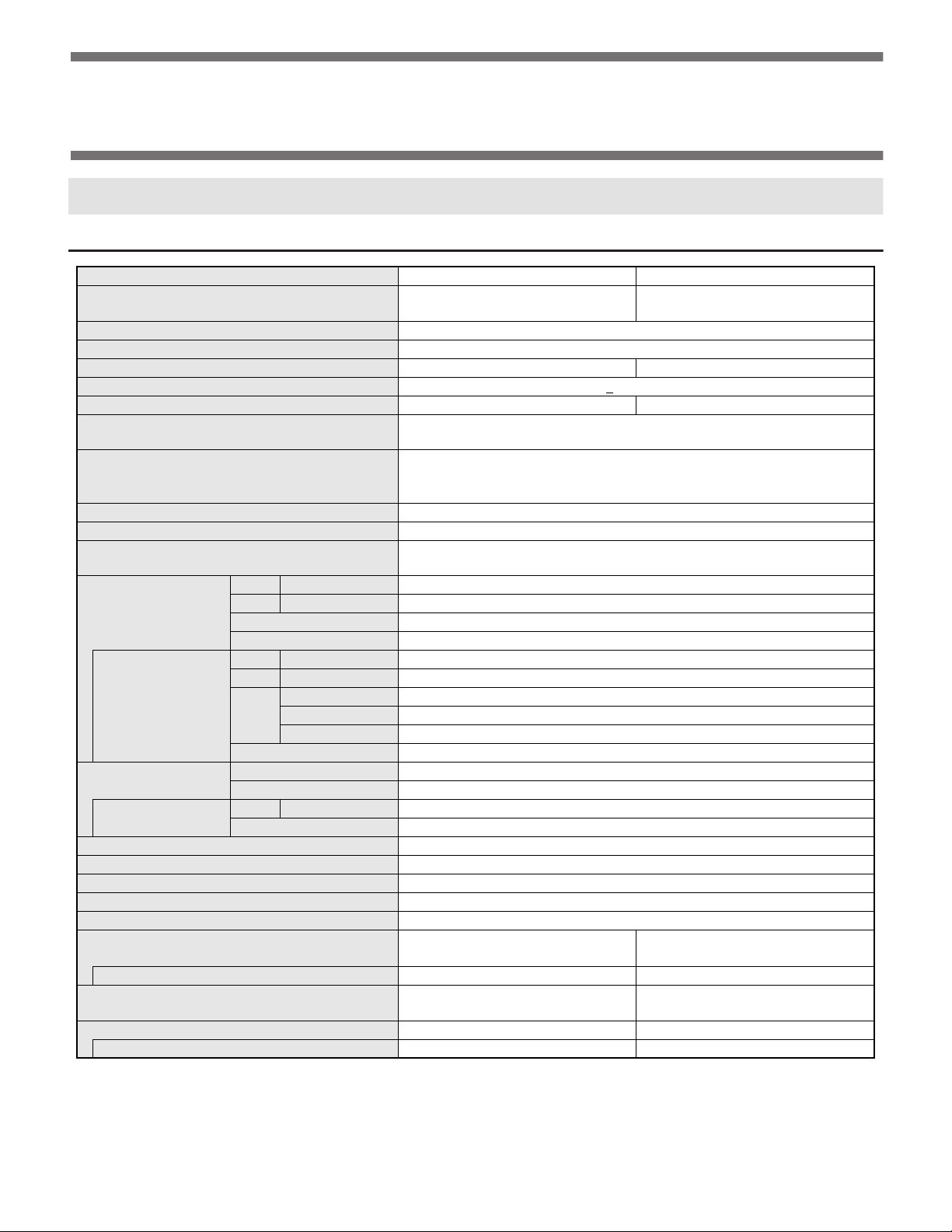
1. SPECIFICATIONS
1 - 1. OUTLINE
Model PN-E601 PN-E521
LCD component
60” Class [60-1/16 inch (152.5cm) diagonal]
TFT LCD
Max. resolution (pixels) 1920 x 1080
Max. colors Approx. 1.06 billion colors
Pixel pitch 0.692 mm (H) x 0.692 mm (V) 0.600 mm (H) x 0.600 mm (V)
Viewing angle 176° right/left/up/down (contrast ratio>10)
Screen active area inch (mm) 52-5/16 x 29-7/16 (1329.1 x 747.6) 45-3/8 x 25-1/2 (1152.0 x 648.0)
n
Computer input signal
Sync signal
Digital (DVI 1.0 standard-compliant)
n
Analog RGB (0.7 Vp-p) [75Ω]
n
Horizontal/vertical separate (TTL: positive/negative)
n
Sync-on-green
n
Composite sync (TTL: positive/negative)
Video color system NTSC (3.58MHz)/NTSC (4.43MHz)/PAL/PAL-60/SECAM
Plug and play VESA DDC2B
n
Power management
VESA DPMS
n
DVI DMPM
PC/AV Digital HDMI x 1
Input terminals
PC Analog Mini D-SUB 15 pin, 3 rows x 1
Audio 3.5 mm mini stereo jack x 1
Serial (RS-232C) D-SUB 9 pin x 1
PC/AV Digital DVI-D 24 pin (HDCP compatible) x 1
*1 *2
x 1
When PN-ZB01
(optional) is attached
PC Analog BNC
Composite video BNC x 1
AV
S-video x 1
Component BNC (Y, Cb/Pb, Cr/Pr) *1 x 1
Audio RCA pin (L/R) x 2
Output terminals
When PN-ZB01
(optional) is attached
Audio RCA pin (L/R) x 1
Serial (RS-232C) D-SUB 9 pin x 1
PC/AV Digital DVI-D 24 pin x 1
External speaker 10 W + 10 W [6Ω]
LAN terminal [When PN-ZB01 (optional) is attached] 10 BASE-T/100 BASE-TX
Speaker output 10 W + 10 W
Power requirement AC 100 V - 240 V, 50/60 Hz
Operating temperature 32°F to 104°F (0°C to 40°C)
Operating humidity 20% to 80% (no condensation)
Power co nsumpt i on (No a udio in put /maxi m um/i npu t
signal waiting mode
*3
/standby mode *4)
395 W/400 W/2.0 W/2.0 W 260 W / 265 W / 2.0 W / 2.0 W
When PN-ZB01 (optional) is attached 400 W/410 W/4.8 W/4.5 W 265 W / 270 W / 4.8 W / 4.5 W
Dimensions (exc luding protrus ions) inc h (mm)
Approx. 54-1/8 (W) x 4-7/16 (D) x 31-1/4
(H) (1,374 x 112 x 793)
Weight lbs. (kg) Approx. 77.2 (35) Approx. 61.7 (28)
When PN-ZB01 (optional) is attached Approx. 79.4 (36) Approx. 63.9 (29)
*1 Cannot be used simultaneously.
*2 Does not support plug and play.
*3 When AUTO INPUT CHANGE is set to OFF.
*4 When STANDBY MODE is set to STANDARD. When STANDBY MODE is set to LOW POWER, PN-E601: 0.8 W, PN-E521: 0.8 W.
52” Class [52-1/16 inch (132.2cm) diagonal]
TFT LCD
Approx. 47-9/16 (W) x 4-3/16 (D) x 27-3/8
(H) (1,208 x 106 x 695)
PN-E601 OUTLINE OF THE PRODUCT
1 – 1
Page 6
CHAPTER 1. OUTLINE OF THE PRODUCT
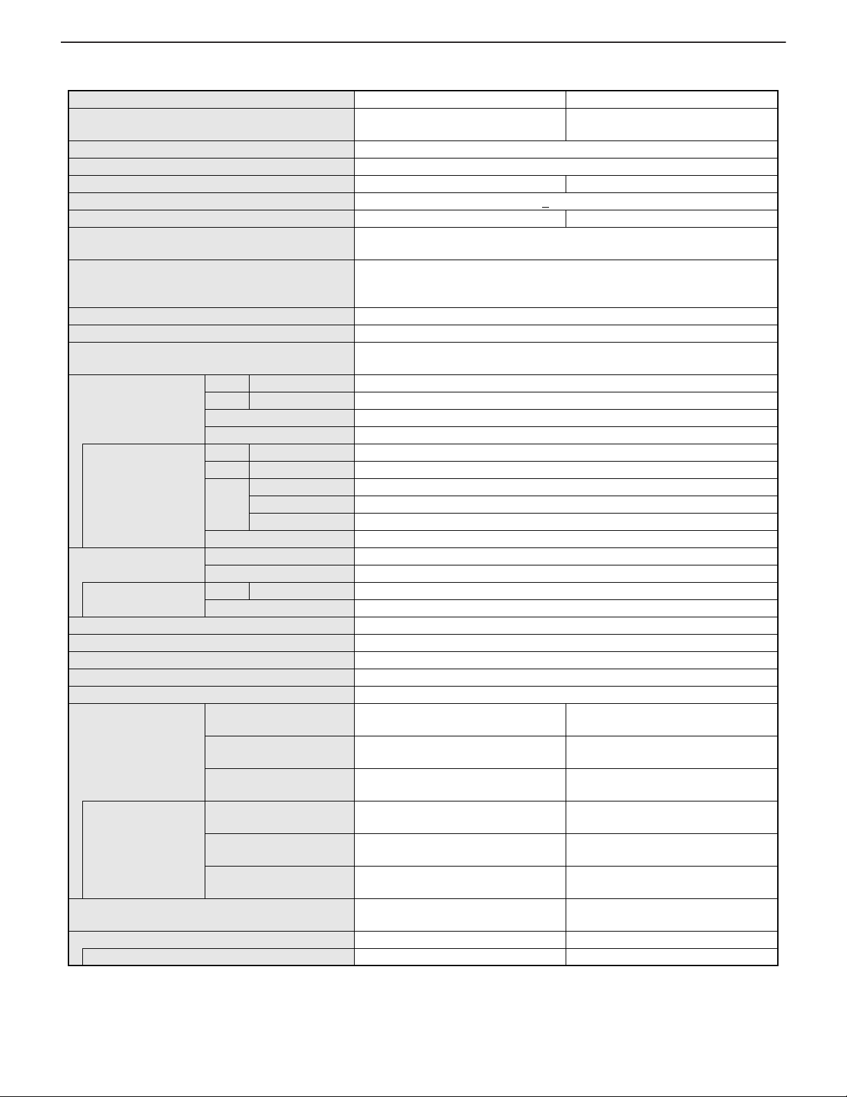
Model PN-E471 PN-E421
LCD component
47” Class [46 -15/16 inch (119.3cm) d iagonal]
TFT LCD
Max. resolution (pixels) 1920 x 1080
Max. colors Approx. 1.06 billion colors
Pixel pitch 0.542mm (H) x 0.542mm (V) 0.485mm (H) x 0.485mm (V)
Viewing angle 178° right/left/up/down (contrast ratio > 10)
Screen active area inch (mm) 40-15/16 x 23 (1039.7 x 584.8) 36-5/8 x 20-5/8 (930.2 x 523.3)
n
Computer input signal
Sync signal
Digital (DVI 1.0 standard-compliant)
n
Analog RGB (0.7 Vp-p) [75Ω]
n
Horizontal/vertical separate (TTL: positive/negative)
n
Sync-on-green
n
Composite sync (TTL: positive/negative)
Video color system NTSC (3.58MHz)/NTSC (4.43MHz)/PAL/PAL-60/SECAM
Plug and play VESA DDC2B
n
Power management
VESA DPMS
n
DVI DMPM
PC/AV Digital HDMI x 1
Input terminals
PC Analog Mini D-SUB 15 pin, 3 rows x 1
Audio 3.5 mm mini stereo jack x 1
Serial (RS-232C) D-SUB 9 pin x 1
PC/AV Digital DVI-D 24 pin (HDCP compatible) x 1
*1 *2
x 1
*1
x 1
When PN-ZB01
(optional) is attached
PC Analog BNC
Composite video BNC x 1
AV
S-video x 1
Component BNC (Y, Cb/Pb, Cr/Pr)
Audio RCA pin (L/R) x 2
Output terminals
When PN-ZB01
(optional) is attached
Audio RCA pin (L/R) x 1
Serial (RS-232C) D-SUB 9 pin x 1
PC/AV Digital DVI-D 24 pin x 1
External speaker 10W + 10W [6Ω]
LAN terminal [When PN-ZB01 (optional) is attached] 10 BASE-T/100 BASE-TX
Speaker output 10W + 10W
Power requirement AC 100V - 240V, 50/60Hz
Operating temperature 32°F to 104°F (0°C to 40°C)
Operating humidity 20% to 80% (no condensation)
Factory Setting (Audio
225W/230W 195W/200W
input: enabled / disabled)
Power consumption
Maximum (Audio input:
enabled / disabled)
Input signal waiting mode *3
/ Standby mode
*4
Factory Setting (Audio
255W/260W 220W/225W
2W/2W 2W/2W
225W/235W 200W/205W
input: enabled / disabled)
When PN-ZB01
(optional) is attached
Dimensions (excluding protrusi ons ) inch (mm)
Maximum (Audio input:
enabled / disabled)
Input signal waiting mode *3
/ Standby mode
*4
260W/265W 225W/230W
4.8W/4.5W 5W/4.5W
Approx. 42-5/8 ( W) x 4-3 /8 (D) x 24-3/ 4 (H)
(1,083 x 111 x 628)
Weight lbs. (kg) Approx. 56.2 (25.5) Approx. 48.5 (22)
When PN-ZB01 (optional) is attached Approx. 57.3 (26) Approx. 49.6 (22.5)
*1 Cannot be used simultaneously.
*2 Does not support plug and play.
*3 When AUTO INPUT CHANGE is set to OFF.
*4 When STANDBY MODE is set to STANDARD. When STANDBY MODE is set to LOW POWER, PN-E471: 0.8 W, PN-E421: 0.8 W.
42” Class [42-1/16 inch (106.7cm) diagonal]
TFT LCD
Approx. 38-5/16 (W) x 4-15/16 (D) x
22-5/16 (H) (973 x 126 x 566)
PN-E601 OUTLINE OF THE PRODUCT
1 – 2
Page 7
CHAPTER 1. OUTLINE OF THE PRODUCT
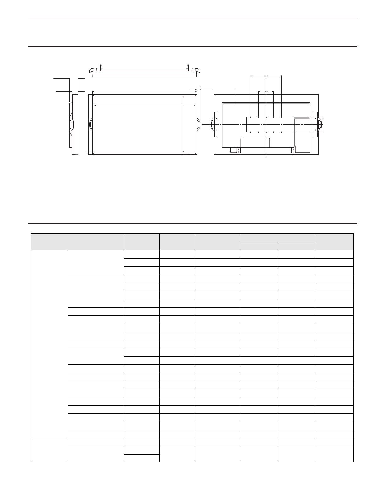
1 - 2. DIMENSIONAL DRAWINGS
4-7/16
[112]
3-1/8
[80]
45-3/8 [1153]
54-1/8 [1374]
1-9/16
[40]
VESA
holes
7-7/8
[200]
3-15/16
[100]
7-7/8
[200]
3-15/16
[100]
Opening width (52-1/2 [1334])
31-1/4 [793]
Opening height
(29-5/8 [753])
7-7/8 [200]
Unit: inch [mm]
When mounting the monitor, be sure to use a wall-mount bracket that complies with the VESA-compatible mounting method.
SHARP recommends using M6 screws and tighten the screws.
Note that screw hole depth of the monitor is 3/8 inch (10 mm). Loose mounting may cause the product to fall, resulting in serious personal injuries as
well as damage to the product. The screw and hole should come together with over 5/16 inch (8 mm) length of thread. Use a bracket which has been
approved for UL1678 standard, and which can endure at least 4 times or more the weight of the monitor.
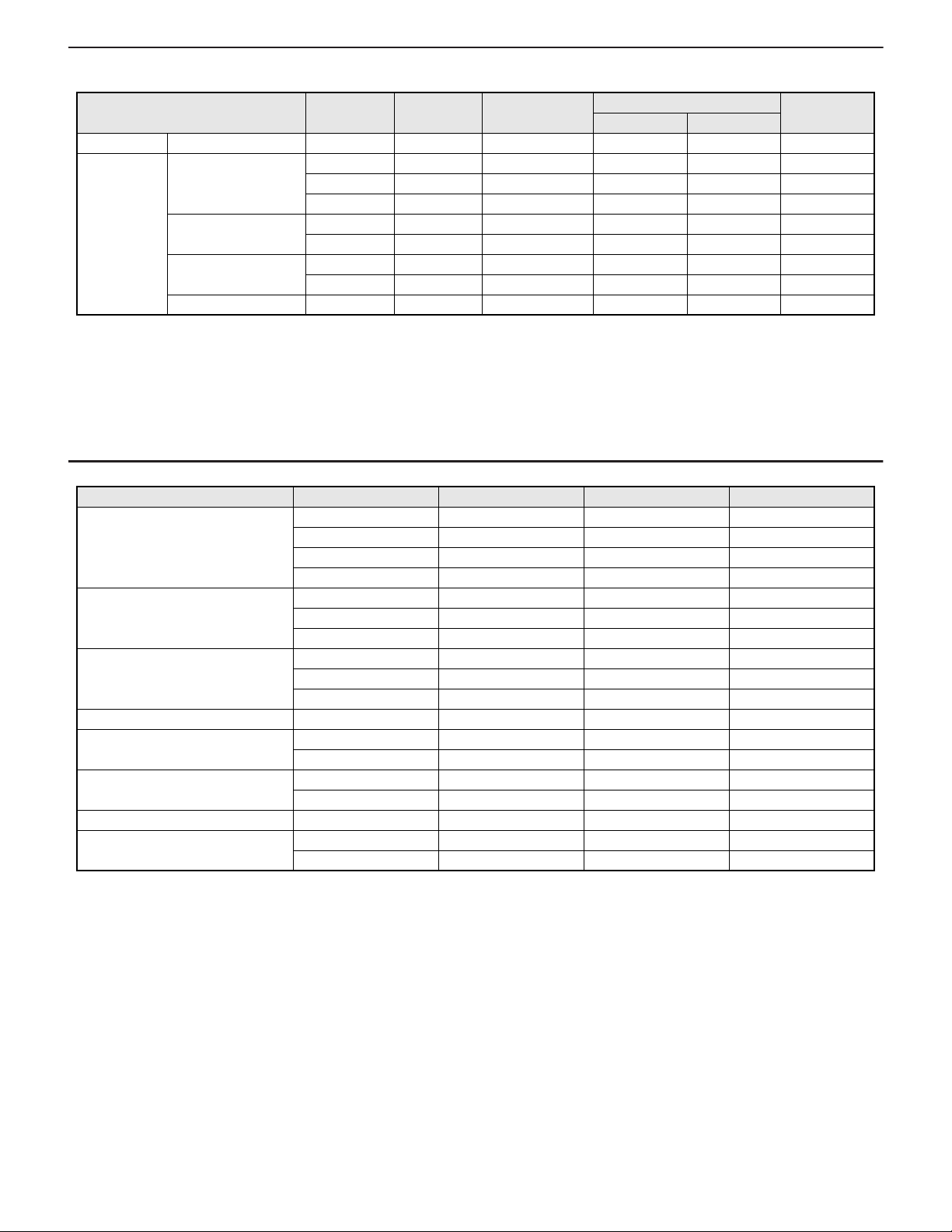
1 - 3. COMPATIBLE SIGNAL TIMING (PC)
Screen resolution Hsync Vsync Dot frequency
DVI
*2
Digital
HDMI
VESA 640 x 480 31.5kHz 60Hz 25.175MHz Yes Yes Yes
37.9kHz 72Hz 31.5MHz Yes Yes Yes
37.5kHz 75Hz 31.5MHz Yes Yes Yes
800 x 600 35.1kHz 56Hz 36.0MHz --- --- Yes
37.9kHz 60Hz 40.0MHz Yes Yes Yes
48.1kHz 72Hz 50.0MHz Yes Yes Yes
46.9kHz 75Hz 49.5MHz Yes Yes Yes
848 x 480 31.0kHz 60Hz 33.75MHz Yes --- Yes
1024 x 768 48.4kHz 60Hz 65.0MHz Yes Yes Yes
56.5kHz 70Hz 75.0MHz Yes Yes Yes
60.0kHz 75Hz 78.75MHz Yes Yes Yes
1152 x 864 67.5kHz 75Hz 108.0MHz Yes Yes Yes
1280 x 768 47.8kHz 60Hz 79.5MHz Yes --- Yes
60.3kHz 75Hz 102.25MHz Yes --- Yes
1280 x 800
49.7kHz 60Hz 83.5MHz Yes Yes Yes
1280 x 960 60.0kHz 60Hz 108.0MHz Yes Yes Yes
1280 x 1024 64.0kHz 60Hz 108.0MHz Yes Yes Yes
80.0kHz 75Hz 135.0MHz Yes Yes Yes
1360 x 768 47.7kHz 60Hz 85.5MHz Yes Yes Yes
1400 x 1050 65.3kHz 60Hz 121.75MHz Yes Yes Yes
1600 x 1200
*1
75.0kHz 60Hz 162.0MHz Yes Yes Yes
1680 x 1050 65.3kHz 60Hz 146.25MHz Yes Yes Yes
1920 x 1200
*1
74.0kHz 60Hz 154.0MHz Yes Yes Yes
Wide 1280 x 720 44.7kHz 60Hz 74.4MHz Yes Yes Yes
1920 x 1080 66.3kHz 60Hz 148.5MHz Yes Yes Yes
67.5kHz
Analog
(D-SUB/RGB
*2
)
PN-E601 OUTLINE OF THE PRODUCT
1 – 3
Page 8
CHAPTER 1. OUTLINE OF THE PRODUCT
Screen resolution Hsync Vsync Dot frequency
DVI
*2
Digital
HDMI
(D-SUB/RGB
US TEXT 720 x 400 31.5kHz 70Hz 28.3MHz Yes Yes Yes
Sun 1024 x 768 48.3kHz 60Hz 64.13MHz --- --- Yes
53.6kHz 66Hz 70.4MHz --- --- Yes
56.6kHz 70Hz 74.25MHz --- --- Yes
1152 x 900 61.8kHz 66Hz 94.88MHz --- --- Yes
71.8kHz 76.2Hz 108.23MHz --- --- Yes
1280 x 1024 71.7kHz 67.2Hz 117.01MHz --- --- Yes
81.1kHz 76Hz 134.99MHz --- --- Yes
1600 x 1000 68.6kHz 66Hz 135.76MHz --- --- Yes
*1 Displays a reduced image.
*2 Available when the PN-ZB01 (optional) is attached.
* All are compliant only with non-interlaced.
* Depending on the connected PC, images may not be displayed properly even if the compatible signal described above is input.
* The frequency values for the Sun are reference values.
1 - 4. COMPATIBLE SIGNAL TIMING (AV)
Screen resolution Frequency DVI-D
1920 x 1080p 24Hz --- Yes ---
50Hz Yes Yes Yes
59.94Hz Yes Yes Yes
60Hz Yes Yes Yes
1920 x 1080i 50Hz Yes Yes Yes
59.94Hz Yes Yes Yes
60Hz Yes Yes Yes
1280 x 720p 50Hz Yes Yes Yes
59.94Hz Yes Yes Yes
60Hz Yes Yes Yes
720 x 576p 50Hz Yes Yes Yes
720 x 480p 59.94Hz Yes Yes Yes
60Hz Yes Yes Yes
640 x 480p (VGA) 59.94Hz Yes Yes ---
60Hz Yes Yes ---
720 (1440) x 576 50Hz --- Yes Yes
720 (1440) x 480i 59.94Hz --- Yes Yes
60Hz --- Yes Yes
*1 Available when the PN-ZB01 (optional) is attached.
*1
HDMI Component
Analog
*1
*2
)
PN-E601 OUTLINE OF THE PRODUCT
1 – 4
Page 9
CHAPTER 1. OUTLINE OF THE PRODUCT
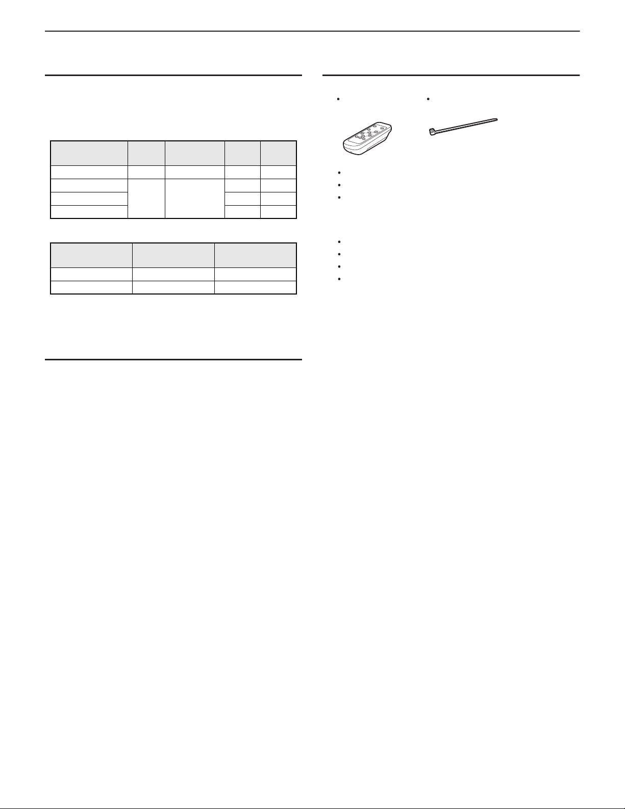
* Place a blank sticker onto the SHARP logo to cover the logo.
Remote control
unit: 1
Power cord: 1
R-6 battery ("AA" size): 2
CD-ROM (Utility Disk for Windows): 1
Operation manual: 1
Stand hole protection cover: 2
Vertical logo sticker: 2
Blank sticker: 1
Cable clamp: 2
* Sharp Corporation holds authorship rights to the
Utility Disk program. Do not reproduce it without
permission.
* For environmental protection!
Do not dispose of batteries in household waste. Follow the
disposal instructions for your area.
1 - 5. POWER MANAGEMENT
This monitor conforms to VESA DPMS and DVI DMPM. Both your video
card and computer must support the same standard in order for the
monitor’s power management function to work.
DPMS: DISPLAY POWER MANAGEMENT SIGNALING
DPMS Screen
ON STATE Display 400W
STANDBY No
SUSPEND Yes No
OFF STATE No No
DMPM: DIGITAL MONITOR POWER MANAGEMENT
DMPM Screen
Monitor ON Display 400W
Active OFF No display 2.0W
*1 When PN-ZB01 (optional) is not connected.
*2 When AUTO INPUT CHANGE is set to OFF.
display
Power
consumption
2.0W
*1
*1*2
Hsync Vsync
Yes Yes
No Yes
Power
consumption
*1
*1*2
1 - 6. DDC (PLUG AND PLAY)
1 - 7. SUPPLIED ACCESSORIES
The monitor supports the VESA DDC (Display Data Channel) standard.
DDC is a signal standard for plug and play between monitors and computers. Information about resolution and other parameters is exchanged
between the two. This function can be used if the computer supports
DDC and it has been configured to detect plug-and-play monitors.
There are several types of DDC, depending on the communication
method used. This monitor supports DDC2B.
PN-E601 OUTLINE OF THE PRODUCT
1 – 5
Page 10
CHAPTER 1. OUTLINE OF THE PRODUCT
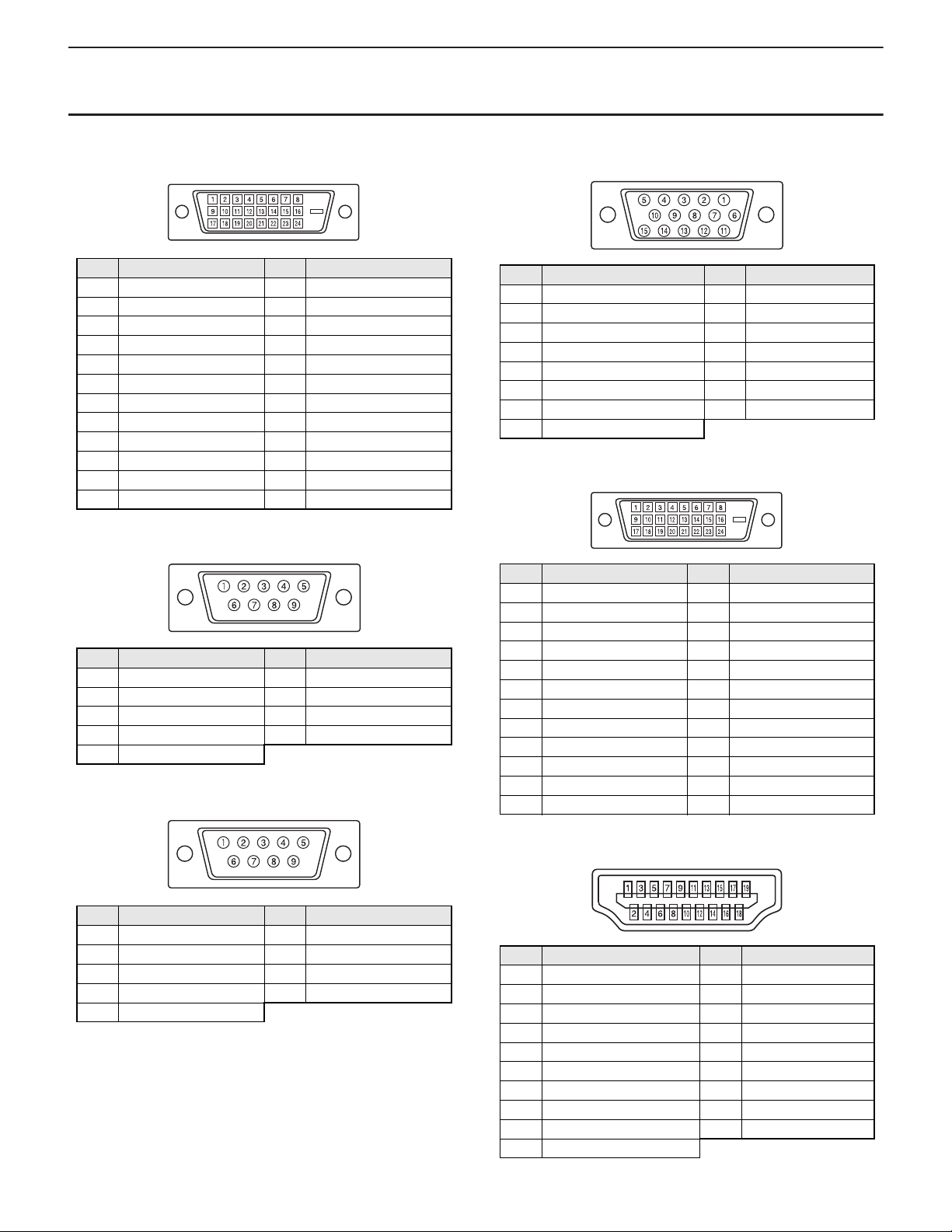
(DVI-D 24 PIN)
1 - 8. LAYOUT OF TERMINAL PINS
■ PC/AV DVI-D INPUT TERMINAL PINS
No. Function No. Function
1 TMDS data 2- 13 N.C.
2 TMDS data 2+ 14 +5V
3 TMDS data 2/4 shield 15 GND
4 N.C. 16 Hot-plug detection
5 N.C. 17 TMDS data 06 DDC clock 18 TMDS data 0+
7 DDC data 1 9 TMDS data 0/5 shield
8 N.C. 20 N.C.
9 TMDS data 1- 21 N.C.
10 TMDS data 1+ 22 TMDS clock shield
11 TMDS data 1/3 shield 23 TMDS clock+
12 N.C. 24 TMDS clock-
■ RS-232C INPUT TERMINAL PINS
(D-SUB 9 PIN)
No. Function No. Function
1N.C. 6N.C.
2 Transmitted data 7 N.C.
3 Received data 8 N.C.
4N.C. 9N.C.
5GND
■ RS-232C OUTPUT TERMINAL PINS
(D-sub 9 PIN)
■ PC D-SUB INPUT TERMINAL PINS
(Mini D-SUB 15 PIN)
No. Function No. Function
1 Red video signal input 9 + 5V
2 Green video signal input 10 GND
3 Blue video signal input 11 N.C.
4 N.C. 12 DDC data
5 GND 13 Hs ync signal input
6 GND for red video signal 14 Vsync signal input
7 GND for green video signal 15 DDC clock
8 GND for blue video signal
■ PC/AV DVI-D OUTPUT TERMINAL PINS
(DVI-D 24 PIN)
No. Function No. Function
1 TMDS data 2- 13 N.C.
2 TMDS data 2+ 14 +5V
3 TMDS data 2/4 shield 15 GND
4 N.C. 16 Hot-plug detection
5 N.C. 17 TMDS data 06 DDC clock 18 TMDS data 0+
7 DDC data 19 TMDS data 0/5 shield
8 N.C. 20 N.C.
9 TMDS data 1- 21 N.C.
10 TMDS data 1+ 22 TMDS clock shield
11 TMDS data 1/3 shield 23 TMDS clock+
12 N.C. 24 TMDS clock-
■ PC/AV HDMI INPUT TERMINAL PINS
TM
(HDMI CONNECTOR)
No. Function No. Function
1N.C. 6N.C.
2 Received data 7 N.C.
3 Transmitted data 8 N.C.
4N.C. 9N.C.
5GND
No. Function No. Function
1 TMDS data 2+ 11 TMDS clock shield
2 TMDS data 2 shield 12 TMDS clock-
3 TMDS data 2- 13 CEC
4 TMDS data 1+ 14 N.C.
5 TMDS data 1 shield 15 SCL
6 TMDS data 1- 16 SDA
7 TMDS data 0+ 17 DDC/CEC GND
8 TMDS data 0 shield 18 +5V
9 TMDS data 0- 19 Hot-plug detection
10 TMDS clock+
PN-E601 OUTLINE OF THE PRODUCT
1 – 6
Page 11
CHAPTER 1. OUTLINE OF THE PRODUCT
When the PN-ZB01 (optional) is attached
G
H
3
1
NMLKO
79
2
564
8
P
R
QST
F
I
J
rear side
front side
(display side)
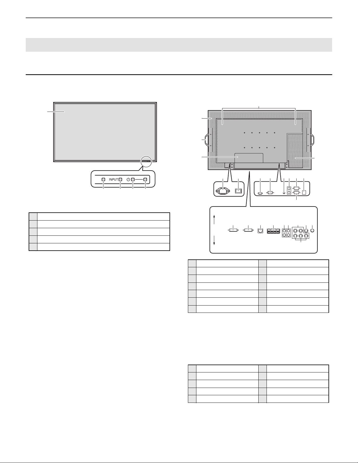
2. PART NAMES AND FUNCTION
2 - 1. DISPLAY
■ FRONT VIEW
1
5432
* Use a pointed object suc h as a pen tip to press the switches at the
front of the monitor.
1 LCD panel
2 Remote control sensor
3 INPUT switch
4 POWER switch
5 Power LED
■ REAR VIEW
1 AC input terminal 8 RS-232C input terminal
2 Main pow er switch 9 Optional terminal
3
PC/AV HDMI input terminal
4 PC D-SUB input terminal G
5 Audio input terminal H Speakers
6 Audio output terminals I Handles
7 RS-232C output terminal J Vents
*1 This terminal is used to connect optional parts for function
expansion.
*2 The connection terminals can be added by attaching the PN-
ZB01 interface extension board (optional).
*3 This section is used to connect optional attachments for function
expansion.
WHEN THE PN-ZB01 (OPTIONAL) IS ATTACHED
K PC/AV DVI-D input terminal P Audio 2 input terminals
L PC/AV DVI-D output terminal Q PC RGB input terminals
M
LAN terminal
N External speaker terminals S
O Audio 1 input terminals T AV S-video input terminal
F Expansion terminal cover
Optional attachment section
R AV component input terminals
AV video input terminal
*1
*2
*3
PN-E601 OUTLINE OF THE PRODUCT
1 – 7
Page 12
CHAPTER 1. OUTLINE OF THE PRODUCT
LAN
Input mode Video Audio
*3
*1
*4
PC DVI-D
PC/AV DVI-D
input terminal
*3
PC/AV DVI-D
input terminal
PC HDMI
PC/AV HDMI
input terminal
*1
PC/AV HDMI
input terminal
PC D-SUB
PC D-SUB
input terminal
PC RGB
PC RGB
input terminals
*
4
AV COMPONENT
input terminals
AV DVI-D
AV HDMI
AV
COMPONENT
AV S-VIDEO
AV S-video
input terminal
AV VIDEO
AV video input
terminal
*2
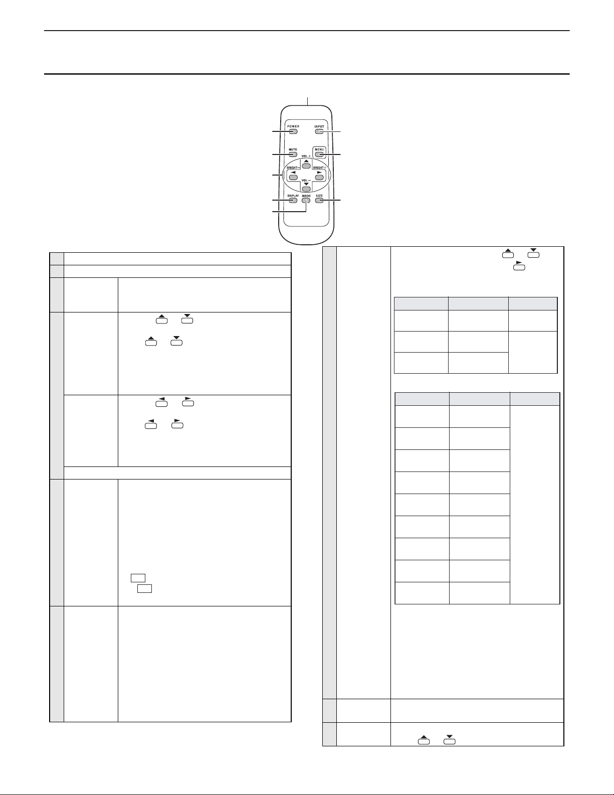
2 - 2. REMOTE CONTROL UNIT
1
1 Signal transmitter
2 POWER button
3 MUTE
button
Turns off the volume temporarily.
Press the [MUTE] button again to turn the
sound back to the previous level.
4 VOL +/-
button
(Volume
adjustment)
Pressing or displays the VOLUME
menu when the menu screen is not displayed.
Press or to adjust the volume of the
sound.
If you do not press any buttons for about 4 seconds, the VOLUME menu automatically disappears.
BRIGHT +/button
(Backlight
adjustment)
Pressing or displays the BRIGHT
menu when the menu screen is not displayed.
Press or to adjust the brightness.
If you do not press any buttons for about 4 seconds, the BRIGHT menu automatically disappears.
Cursor control ( // /) buttons
5 DISPLAY
button
Displays monitor information. When you press
this button again, the display disappears.
When the PN-ZB01 (optional) is attached, the
display changes from INFORMATION1
INFORMATION2 clear display, and so on
every time you press this button.
n
The display disappears automatically after
about 15 seconds.
n
LAN
n
6
MODE
button
(Color mode
selection)
If is displayed in red, there is a duplicate
IP address.
Each time you press this button, the color
mode changes in the following order.
n
STD (Standard) VIVID sRGB STD...
* “sRGB” applies to PC input only.
2
3
4
5
6
is displayed duri n g LAN co mmu nic ati o n.
sRGB is international standard of color
representation specified by IEC (International Electrotechnical Commission).
Color conversion is made in taking account
of liquid crystal’s c haracteristic s and repr esents color tone close to its original image.
PN-E601 OUTLINE OF THE PRODUCT
1 – 8
7
8
9
7
INPUT
button
(Input mode
selection)
The menu is displayed. Press or to
select the input mode, and press to enter.
You can select the input terminal by pressing
the INPUT switch of the monitor.
Input mode Video Audio
PC D-SUB PC D-SUB
PC HDMI
AV HDMI
WHEN THE PN- ZB01 (OPTIONA L) IS ATT ACHE D
*1 Select the terminal to be used in “HDMI”
of “INPUT SELECT”.
*2 Select the terminal for “AUDIO SELECT”
which is used for audio input.
*3 Select the terminal to be used in “DVI” of
“INPUT SELECT”.
*4 Select the terminal to be used in “BNC” of
“INPUT SELECT”.
8
MENU
Displays and turns off the menu screen.
button
9
SIZE button The menu is displayed.
Press or to select the screen size.
input terminal
PC/AV HDMI
input terminal
PC/AV HDMI
input terminal
Audio input
terminal
*2
*1
*1
Page 13
CHAPTER 1. OUTLINE OF THE PRODUCT
CAUTION
■ INSTALLING THE BATTERIES
1 ) Press the cover gently and slide it in the direction of the arrow.
2 ) See the instructions in the compartment and put in the supplied
batteries (R-6 (“AA” size) x 2) with their plus (+) and minus (-) sides
oriented correctly.
3 ) Close the cover.
MEMO
n
When the batteries become exhausted replace them with new
(commercially available) batteries earlier than specified.
n
The supplied batteries (R-6 (“AA” size) x 2) may become
exhausted quickly depending on how they are stored.
n
If you will not use the remote control for a long time, remove the
batteries.
n
Use manganese or alkaline batteries only.
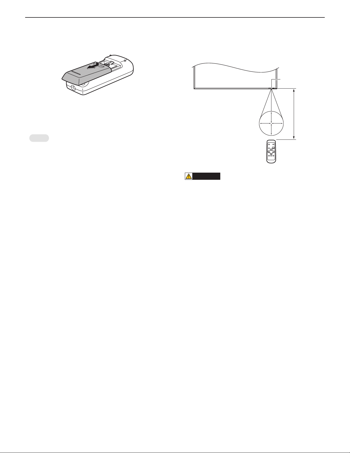
■ REMOTE CONTROL OPERATION RANGE
The operation range of the remote control unit is approx. 16.4 feet (5m)
at an angle of approx 10° from the centre to the top/bottom/right/left of
the remote control sensor.
t
Remote control
sensor
10˚
10˚
n
Do not expose the remote control unit to shock by dropping or
stepping on it. This could lead to a malfunction.
n
Do not expose the remote control unit to liquids, and do not place
it in an area with high humidity.
n
The remote control unit may not work properly if the remote control sensor is under direct sunlight or strong lighting.
n
Objects between the remote control unit and the remote cont rol
sensor may prevent proper operation.
n
Replace the batteries when they run low as this may shorten the
remote control’s operation range.
n
If a fluorescent light is illuminated near the remote control unit, it
may interfere with proper operation.
n
Do not use it with the remote control of other equipment such as
air conditioner, stereo components, etc.
10˚10˚
16.4 feet
(5 m)
PN-E601 OUTLINE OF THE PRODUCT
1 – 9
Page 14
CHAPTER 1. OUTLINE OF THE PRODUCT
Main screen
Sub
screen
Main screen
Sub
screen
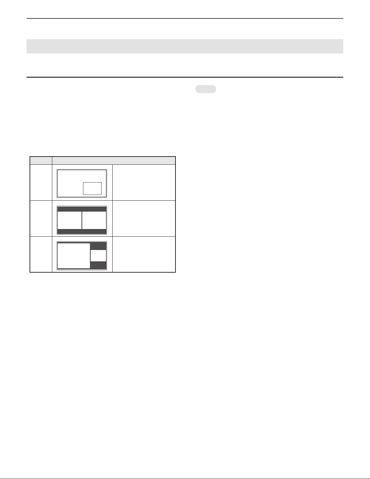
3. SCREEN DISPLAY
3 - 1. DUAL SCREEN DISPLAY
You can display the screens of the PC input signal and AV input signal
simultaneously.
Set this function with “PIP MODES” in the PIP/PbyP menu.
n
The currently selected input signal is displayed on the main screen.
n
You cannot simultaneously display the screens of signals of the same
type, such as two types of PC input signals or two types of AV input
signals.
n
The dual screen display cannot be used with the combination of PC
DVI-D and AV HDMI or of AV DVI-D and PC HDMI.
Mode Screen display
PIP A sub screen is displayed
inside a main screen.
PbyP A main screen and a sub
screen are displayed in a
Main
screen
Sub
screen
line.
PbyP2 Displays a main screen
which measures 1280 pix els
in the longest dire ction and a
sub screen in a line.
MEMO
n
You might infringe on a copyright of the author which is protected
by copyright law when you display the images of the computer
screen and television/VCR simultaneously for profit-making or t o
show the image to the public.
n
The screen size for dual-screen display is the same as the
screen size for single-screen display. The Dot by Dot screen is
displayed in “NORMAL” size except when it is set as the PIP
main screen.
n
When dual-screen display is selected, the AUTO INPUT
CHANGE function is disabled.
n
When dual-screen display is selected, the screen cannot be
enlarged.
n
When dual-screen display is selected, the “INPUT SELECT”
options cannot be set.
PN-E601 OUTLINE OF THE PRODUCT
1 – 10
Page 15
CHAPTER 1. OUTLINE OF THE PRODUCT
MEMO
12345
1
2
3
4
5
54 32 1
1
2
3
4
5
(1,2)
(1,3)
(1,4)
(3,2)
(3,3)
(3,4)
(4,2)
(4,3)
(4,4)
(1,1)(3,1)
(1,5)(3,5)(4,5)
(4,1)
(5,2)
(5,3)
(5,5)
(5,4)
(5,1)
(2,2)
(2,3)
(2,4)
(2,1)
(2,5)
(1,2)
(1,3)
(1,4)
(2,2)
(2,3)
(2,4)
(3,2)
(3,3)
(3,4)
(4,2)
(4,3)
(4,4)
(1,1) (2,1) (3,1)
(5,2)
(5,3)
(1,5) (2,5) (3,5) (4,5) (5,5)
(5,4)
(5,1)(4,1)
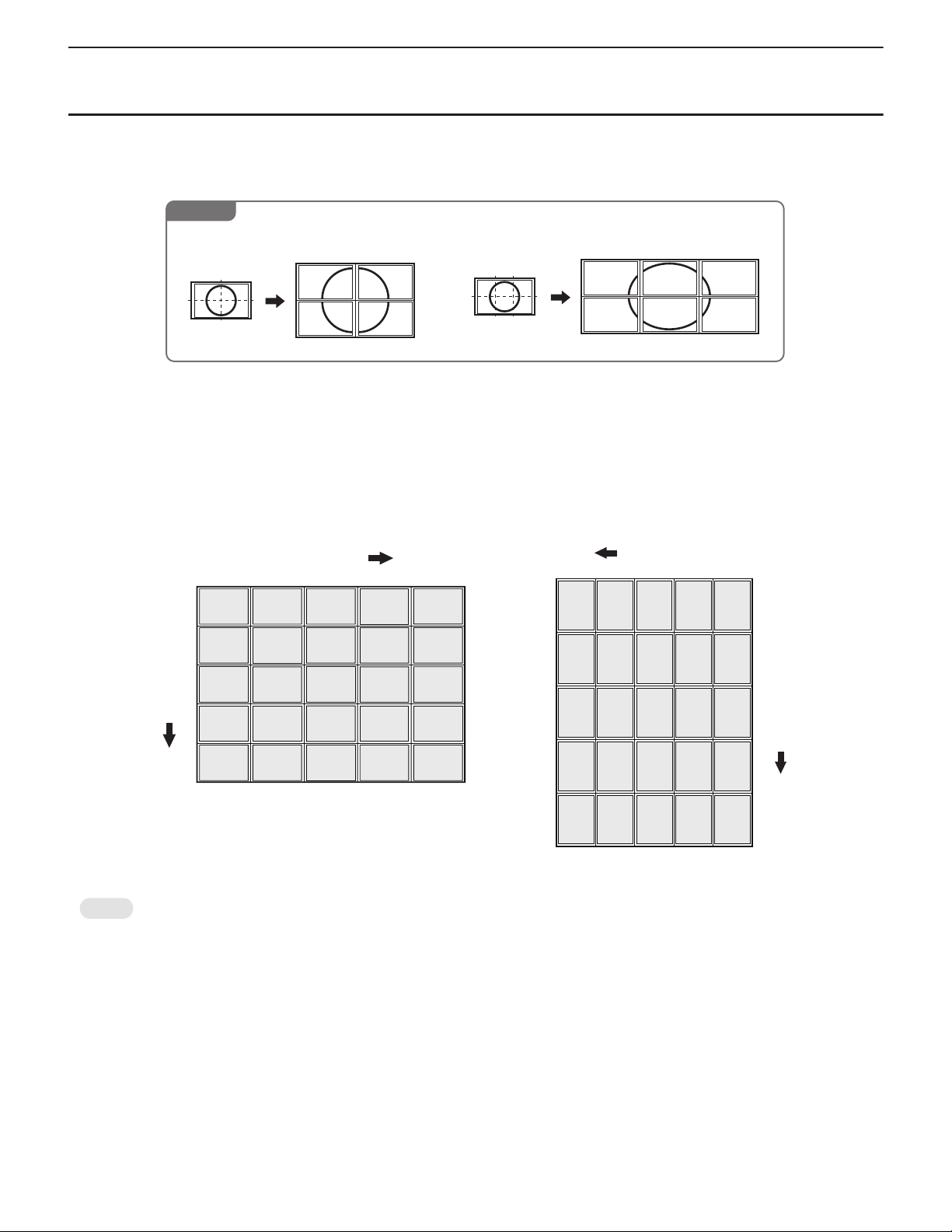
IN HORIZONTAL ORIENTATION
ENLARGE H
ENLARGE V
IN VERTICAL ORIENTATION
ENLARGE H
ENLARGE V
3 - 2. ENLARGE
n
You can align several monitors and integrate them into a single large screen to display.
n
Up to five monitors can be aligned in both the longest and shortest directions.
n
Each monitor displays enlarged views of separated images.
Example
Horizontal direction: 2 monitors
Vertical direction: 2 monitors
■ SETTING PROCEDURE
In the ENLARGE menu, set ENLARGE H/V and ENLARGE-POS H/V.
1 ) Set the number of monitors aligned in the horizontal direction in ENLARGE H.
2 ) Set the number of monitors aligned in the vertical direction in ENLARGE V.
3 ) Set the section of the separated image to be displayed on each monitor in ENLARGE-POS H and ENLARGE-POS V.
Horizontal direction: 3 monitors
Vertical direction: 2 monitors
* The numbers in parentheses are the setting values in (ENLARGE-POS H, ENLARGE-POS V) format.
n
AV input signals cannot be used for the Enlarge function.
n
When Enlarge is used, the AUTO INPUT CHANGE function is disabled.
n
To cancel the enlargement, set 1 for ENLARGE H and ENLARGE V respectively.
PN-E601 OUTLINE OF THE PRODUCT
1 – 11
Page 16
CHAPTER 1. OUTLINE OF THE PRODUCT
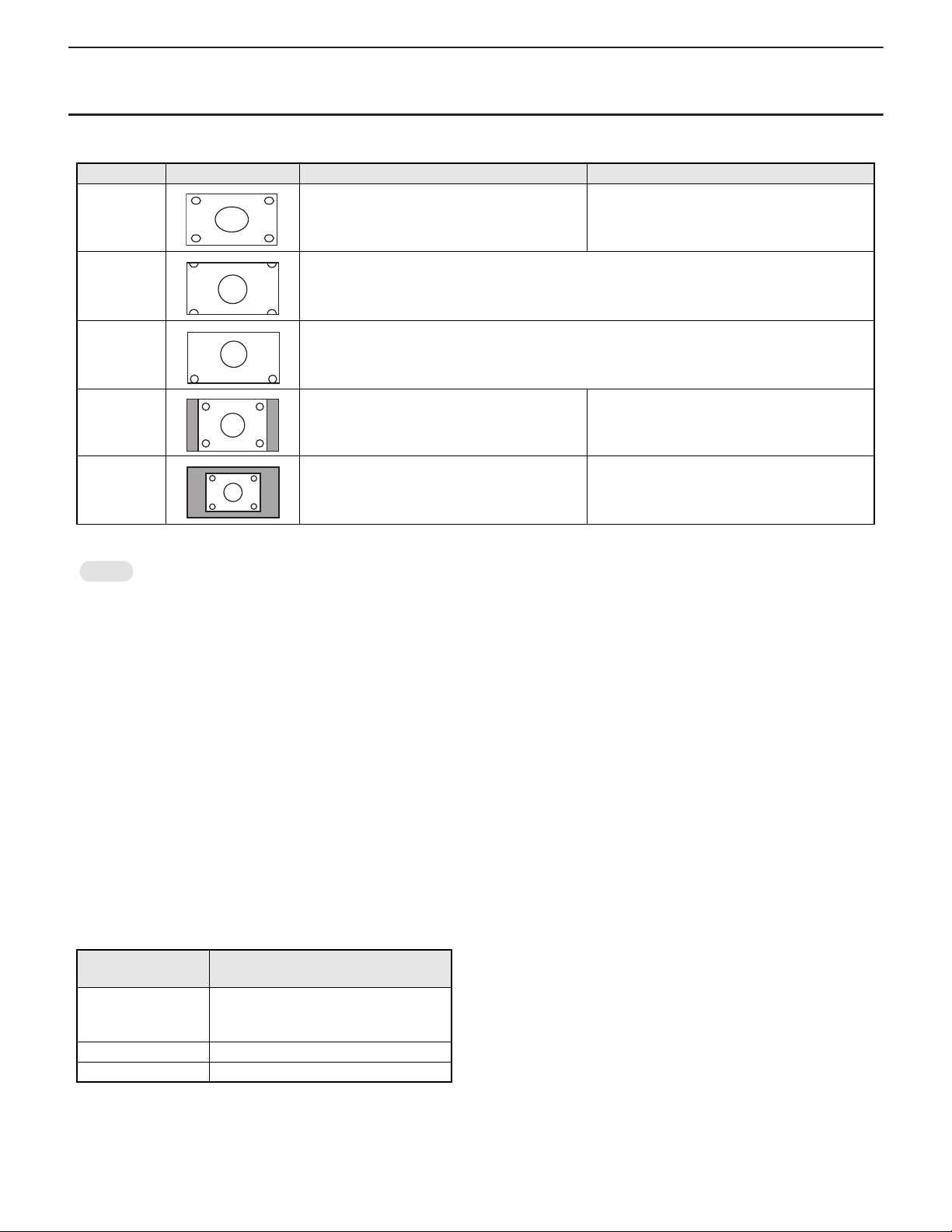
3 - 3. SWITCHING THE SCREEN SIZE
Even when the screen size is changed, the display may remain the same depending on the input signal.
Mode Screen display PC input AV input
WIDE Displays image so it fills the entire screen. An image with a 4:3 aspect ratio is stretched to fill
the entire screen.
ZOOM 1 An image with a 4:3 aspect ratio is enlarged to fill the entire screen without changing the aspect ratio.
The edges of the image may be cut off.
ZOOM 2 Use this size if ZOOM 1 cuts off the subtitles.
NORMAL Displays image so it fills the screen without chang-
ing the aspect ratio of the input signals.
Dot by Dot Displays the dots of the signals input from the con-
nected PC as the corresponding dots on the
*1
screen.
*1 With a monitor of screen resolution 1600 x 1200 or 1920 x 1200, selecting “Dot by Dot” displays the “NORMAL” screen.
Displays the entire image of the aspect ratio of 4:3
without changing the aspect ratio.
Displays the dots of the input signals as the corresponding dots on the screen.
MEMO
n
Using this monitor’s screen-size switching or dual-screen display functions to compress or expand the screen for commercial or public viewing
in establishments like cafes or hotels may infringe on the rights of the creators, as protected by Copyright Law, so please be careful.
n
When “Enlarge” is set, the screen size is fixed to “WIDE” mode.
n
When dual-screen display is selected, the screen size cannot be changed.
n
The appearance of the original video may change if you select a screen size with a different aspect ratio than the original image (e.g. TV broadcast or video input from external equipment).
n
When an ordinary non-wide image (4:3) is viewed with the who le screen using the s creen-size switching function of this m onitor, the edge of
the image may be lost or appear distorted. If you wish to respect the creator’s intentions, set the screen size to “NORMAL”.
n
When playing commercial software, parts of the image (like subtitles) may be cropped. In this case select the optimal screen size using the
screen-size switching function of this monitor. With some software, there may be noise or distortion at the edges of the sc reen. This is due to
the characteristics of the software, and is not a malfunction.
n
Depending on the original image size, black bands may remain at the edges of the screen.
■ ZOOM2 SPECIAL SETTING
If you connect a laptop computer with any of the following screen resolutions and black bands appear around the screen, set “ZOOM2 SPECIAL SETTING” of “INPUT SIGNAL” on the OPTION menu to “ON” and then select “ZOOM2” in the SIZE setting.
This displays the area inside the black band.
Laptop computer
resolution
Corresponding signal
1280 x 800 1280 x 1024
1280 x 960
1400 x 1050
*2
1280 x 600 1280 x 720
1024 x 768 1024 x 600
*1 This setting is effective only when the screen resolution, including the black band, is one of the resolutions listed above.
*2 Use the automatic screen adjustment.
*1
PN-E601 OUTLINE OF THE PRODUCT
1 – 12
Page 17
CHAPTER 1. OUTLINE OF THE PRODUCT
Expansion terminal cover
Connector
Connector
4. OPTION
4 - 1. PN-ZB01
■ SUPPLIED ACCESSORIES
n
Expansion Board: 1
n
Terminal label: 1
n
Mounting screws: 1
n
Operation manual: 1
n
Speaker cable core: 2
n
Installation Manual (instructions for SHARP dealers and service engineers): 1
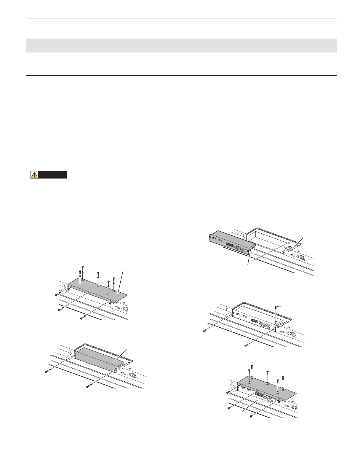
■ INSTALLATION PROCEDURE
CAUTION
n
Do not touch the connectors of this product and LCD MONITOR. The static electricity in your body may cause breakdown.
n
Touch a grounded source to discharge the static electricity in your body before starting operation.
n
The illustrations in this manual are for explanatory purposes and may not exactly represent the actual product.
1 ) Set the main power switch of the monitor to “off” and disconnect
the power from the wall outlet.
2 ) Spread a thick and soft cloth (such as a blanket) on a level surface,
such as a table, and place the monitor on it with its LCD panel facing downward.
3 ) Remove the expansion terminal cover.
Remove 8 screws.
4 ) Remove the dummy plate.
Remove 2 screws.
Dummy plate
5 ) Attach the expansion board.
Fully insert the connector.
6 ) Secure the expansion board.
Secure the board with the supplied mounting screw and the 2
screws removed in Step 4.
Supplied screws
7 ) Attach the expansion terminal cover.
Secure the cover with the 8 screws removed in Step 3).
Give the dummy plate to the customer and ask them to store it.
Always install the dummy plate after removing the expansion
board.
PN-E601 OUTLINE OF THE PRODUCT
(A)
8 ) Affix the terminal label in the area indicated by (A) in the above
illustration.
1 – 13
Page 18
CHAPTER 2. INSTALLATION, ADJUSTMENT, SETTING
CAUTION
Unit: inch [cm]
*1
*1
7-7/8 [20]
2 [5]
2
[5]
2
[5]
FOR THE MONITOR IN
HORIZONTAL ORIENTATION
FOR THE MONITOR IN
VERTICAL ORIENTATION
7-7/8
[20]
2
[5]
2
[5]
2 [5]
*1
Logo
Operation panel
1. INSTALLATION
INSTALLING PRECAUTIONS
n
Since the monitor is heavy, consult your dealer before installing,
removing or moving the monitor.
n
When installing, removing or moving the monitor, ensure that this
is carried out by at least 2 people.
n
A mounting bracket compliant with VESA specifications is required.
Do not use any screw holes other than VESA holes for installation.
n
When moving the monitor, be sure to hold it with the handles both
on the rear and the unit bottom. Do not hold the LCD panel. This
may cause product damage, failure, or injury.
n
Install the monitor with the surface perpendicular to a level surface. If necessary, the monitor may be tilted up to 20 de grees
upward or downward.
n
Mounting the monitor on the wall requires special expertise and
the work must be performed by an authorized SHARP dealer.
You should never attempt to perform any of this work yourself.
Our company will bear no responsibility for accidents or injuries
caused by improper mounting or mishandling.
n
This monitor should be used at an ambient temperature bet ween
32°F (0°C) and 104°F (40°C). Provide enough space around the
monitor to prevent heat from accumulating inside.
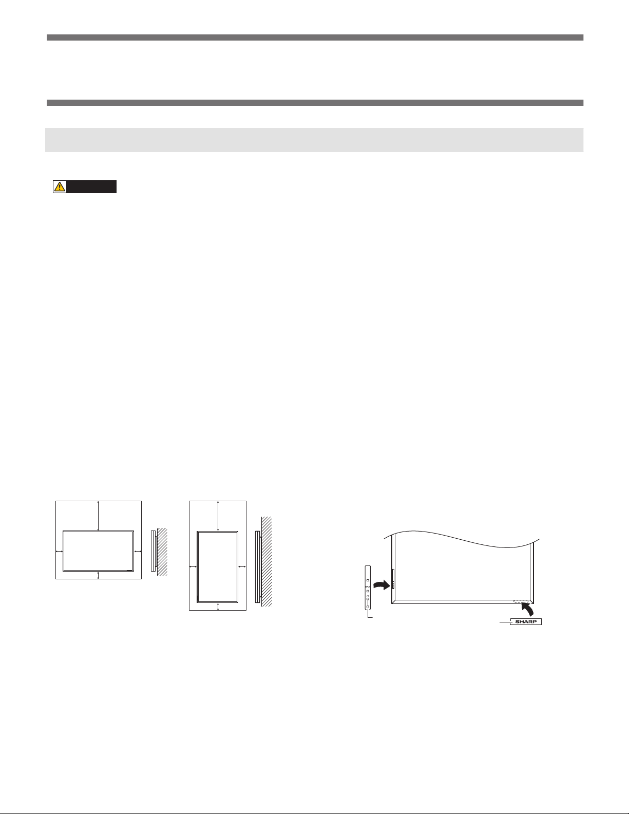
n
Adhere to the following when installing the monitor in the vertical
orientation. Failing to adhere to the following may cause malfunctions.
--- Install the monitor such that the power LED is located on the
downside.
--- Set the “MONITOR on the SETUP” menu to “PORTRAIT”.
n
Do not block any ventilation openings. If the temperature inside
the monitor rises, this could lead to a malfunction.
n
After mounting, it is recommended to take some measures to
prevent the monitor from falling down.
n
Do not place the monitor on a device which generates heat.
n
Be sure to use a wall-mount bracket designed or designated for
mounting the monitor.
n
This monitor is designed to be installed on a concrete wall/ceiling
or pillar. Reinforced work might be necessary for some materials
such as plaster/thin plastic board/wood before starting installation. This monitor and bracket must be installed on a wall which
can endure at least 4 times or more the weight of the monitor.
Install by the most suitable method for the material and the structure.
n
When attaching an optional part, follow the steps described in the
manual for the optional part.
n
Use the supplied vertical logo sticker when you install the monitor
in vertical orientation.
*1 The monitor can be installed close to a wall, etc.
However, the monitor emits heat during operation. Be aware that
heat emitted from the monitor may discolour or alter the wall.
n
If it is difficult to provide this much space for any reason such as
the installation of the monitor inside a housing, or if the ambient
temperature may be outside of the range of 32°F (0°C) to
104°F (40°C), install a fan or take other measures to keep the
ambient temperature within the required range.
*1 Do not remove the factory-affixed sticker but affix the logo sticker
over it. Be careful not to cover the remote control sensor or buttons.
PN-E601 INSTALLATION, ADJUSTMENT, SETTING
2 – 1
Page 19

CHAPTER 2. INSTALLATION, ADJUSTMENT, SETTING
MEMO
1 - 1. CONNECTING PERIPHERAL EQUIPMENT
CAUTION
n
Be sure to turn off the main power switch and disconnect the plug from the power outlet before connecting/disconnecting cables. Also, read the
manual of the equipment to be connected.
n
Be careful not to mix up the input terminal with the output terminal when connecting cables. Mixing up the input and output terminals may cause
malfunctions and the other problems.
n
Images may not be displayed properly depending on the computer (video card) to be connected.
n
A screen with 1920 x 1080 resolution may not be displayed correctly on “PC RGB”. In this case, check the settings of your computer (video
card) to verify that input signals conform to specifications of this monitor.
n
If there is a check box to disable EDID in display control panel, check it when using “PC RGB”.
n
Use the automatic screen adjustment when a PC screen is displayed for the first time using “PC D -SUB” or “P C RGB” , or when the setting of
the PC is changed. The screen is adjusted automatically when “SELF ADJUST” in the OPTION menu is set to “ON”.
n
If the audio output from the playback device is connected directly to speakers or other dev ices, the video on the m onitor may appear delayed
from the audio portion.
Audio should be played through this monit or by connecting the playback device to the monitor’s audio input, and connecting the monitor’s
audio output to the speakers or other devices.
n
The audio input terminals used in each input mode are factory-set as follows.
Input mode Audio input terminal (Factory setting)
PC D-SUB
Audio input terminal
PC DV I-D
PC RGB
AV DVI-D Audio1 input terminal
AV COMPONENT
Audio2 input terminal
AV S-VIDEO
AV VIDEO
PC HDMI
PC/AV HDMI input terminal
AV HDMI
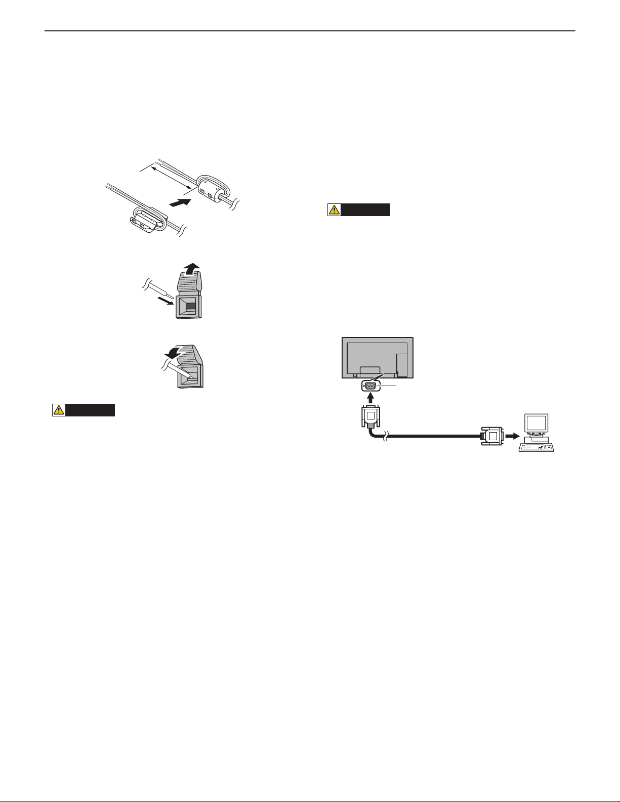
■ CONNECTION WITH A PC OR AV EQUIPMENT
n
Use a commercially available HDMI cable (conforming to the HDMI standard) for PC/AV HDMI input
terminal.
n
Set “HDMI” of “INPUT SELECT” on the OPTION menu according to the device to be connected.
n
Select the audio input terminal to be used in “PC H DMI” or “AV HD MI” of “AUDIO SE LECT” on the
OPTION menu.
When “HDMI” is selected, connection to the audio input terminal is unnecessary.
n
When the PN-ZB01 (optional) is attached, select the audio input terminal to be used in “PC D-SUB”
of “AUDIO SELECT” on the OPTION menu.
n
Use an audio cable without resistance.
n
When the PN-ZB01 (optional) is attached, set the audio input terminal used for each input mode in
“AUDIO SELECT” on the OPTION menu.
n
The output sound varies depending on the input mode.
n
The volume of the output sound can be fixed by setting “AUDIO OUTPUT” on the OPTION menu.
n
It is not possible to control the sound output from the audio output terminals with the AUDIO menu.
Video
input
Audio
input/
output
PC/AV HDMI input terminal
PC D-SUB input terminal
Audio input terminal
Audio output terminals
Monitor
control
RS-232C input terminal
RS-232C output terminal
n
You can control the monitor from a PC by connecting a commercially available RS-232 straight cable
between these terminals and the PC.
PN-E601 INSTALLATION, ADJUSTMENT, SETTING
2 – 2
Page 20
CHAPTER 2. INSTALLATION, ADJUSTMENT, SETTING
■ CONNECTION WHEN THE PN-ZB01 (OPTIONAL) IS ATTACHED
The PN-ZB01 expansion board (optional) allows the use of additional connection terminals.
n
Set “DVI” of “INPUT SELECT” on the OPTION menu according to the device to be connected.
n
Select the audio input terminal to be used in “PC DVI-D” or “AV DVI-D” of “AU DIO SELECT” on th e
OPTION menu.
n
Set “BNC” of “INPUT SELECT” on the O P TION menu to “PC RGB” when using the PC RGB input terminals.
n
Select the audio input terminal to be used in “PC RGB” of “AUDIO SELECT” on the OPTION menu.
n
Set “BNC” of “INPUT SELECT” on the OPTION menu to “A V COMPONENT” when using the AV
component input terminals.
n
Select the audio input terminal to be used in “AV COMPONENT ” of “AUDIO SELECT” on the OPTION
menu.
n
Select the audio input terminal to be used in “AV S-VIDEO” of “AUDIO SELECT” on the OPTION
menu.
n
Select the audio input terminal to be used in “AV VIDEO” of “AUDIO SELECT” on the OPTION menu.
Video
input
PC/AV DVI-D input terminal
PC RGB input terminals
HV
RG B
AV component input
terminals
Cr/Pr Y Cb/Pb
AV S-video input terminal
AV video input terminal
Audio1 input terminals/
Audio2 input terminals
n
Set the audio input terminal to be used in each input m ode in “AUDIO SELECT” on the OPTION
menu.
Audio
input
<LAN TERMINAL>
You can control the monitor from a PC on a network by connecting a commercially available LAN cable between this terminal and a network.
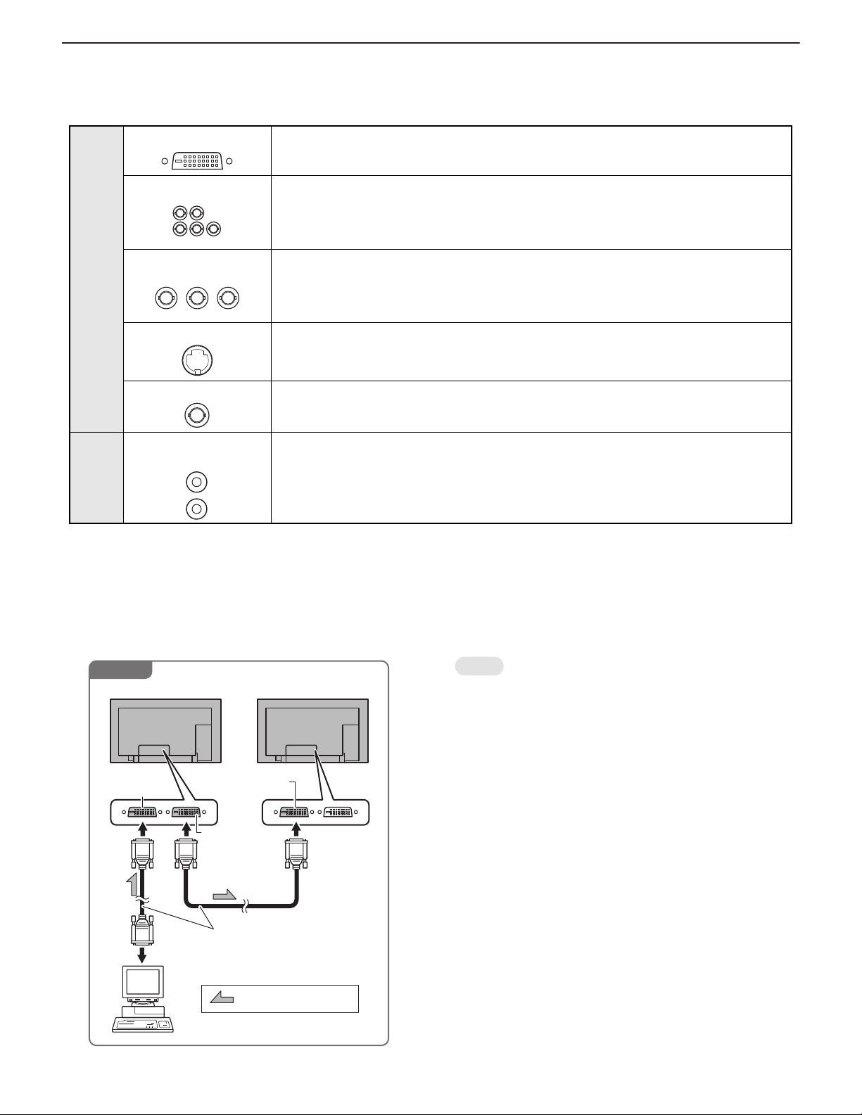
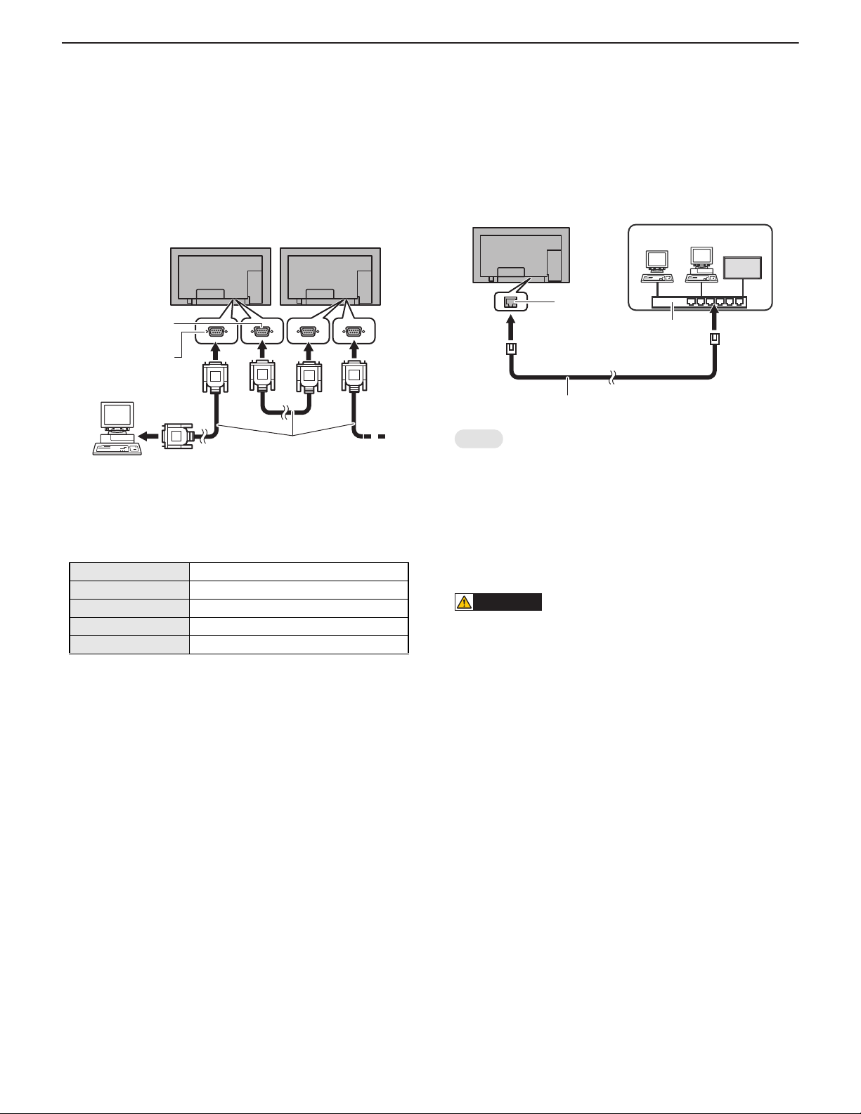
<PC/AV DVI-D OUTPUT TERMINAL>
n
The video of the PC/AV DVI-D input can be output to an external device.
n
Outputting HDCP-encrypted video requires an external device which supports HDCP.
n
This terminal allows the daisy chain connection of up to 5 monitors.
Example
First monitor Second monitor
PC/AV DVI-D
output terminal
To PC digital RGB output terminal
PC/AV DVI-D
input terminals
PC/AV DVI-D
output terminals
Digital signal (DVI) cables
(commercially available)
MEMO
n
The length of the signal cables or surrounding environment may
affect the image quality.
n
The screen may not display properly when using terminals other
than “PC DVI-D”/“AV DVI-D” for the input mode. In this case, turn
off the power to all the monitors connected in a daisy chain and
then turn the power on again.
n
When connecting monitors in a daisy chain set “AUTO INPUT
CHANGE” to “OFF”.
n
Video output is disabled in the following cases.
---When the input mode is “PC HDMI”/“AV HDMI”.
---When PIP SOURCE of the PIP/PbyP menu is set to PC
“HDMI” or “AV HDMI”.
---When the power is turned “off”.
---When the monitor is in input signal waiting mode.
shows the signal flow
PN-E601 INSTALLATION, ADJUSTMENT, SETTING
2 – 3
Page 21
CHAPTER 2. INSTALLATION, ADJUSTMENT, SETTING
CAUTION
Approx.
3-15/16 inch
(10 cm)
<EXTERNAL SPEAKER TERMINALS>
n
To use an external speaker, set “SPEAKER SELECT” on the SET UP
menu to “EXTERNAL”.
n
Be sure to use external speakers with an impedance of 6 Ω and a
rated input of at least 10 W.
1 ) Attach a speaker cable core (included with the PN-Z B01) to the
end of the speaker cable connected to the monitor.
2 ) While pushing the tab, insert the tip of the cable.
3 ) Release the tab.
■ CONTROLLING THE MONITER WITH A PC
(RS-232C)
You can control this monitor from a PC via RS-232C (COM port) on the
PC.
You can also connect multiple monitors via a daisy chain by using a PC.
By assigning ID numbers to each monitor (see page 19), you can make
input mode selection/adjustment or can check the status of a specific
monitor.
You can also connect multiple monitors via a daisy chain by using a PC.
By assigning ID numbers to each monitor, you can make input mode
selection/adjustment or can check the status of a specific monitor.
PRECAUTIONS WHEN THE PN-ZB01 (OPTIONAL) IS
ATTACHED
n
To control the monitor via RS-232C, set RS-232C/LAN SELECT
to RS-232C.
n
You cannot use RS-232C and LAN control simultaneously.
<ONE-TO-ONE CONNECTION WITH A PC>
Connect with RS-232 straight cable between the PC's COM port (RS 232C connector) and the RS-232C input terminal on the monitor.
CAUTION
n
Be sure to connect the + and - terminals and the left and right
speakers properly.
n
Avoid short circuiting the + and - terminals.
n
When “SPEAKER SELECT” is set to “EXTERNAL”, the internal
speaker is disabled.
RS-232C input terminal
PC
To COM port
RS-232 straight cable
(commercially available)
PN-E601 INSTALLATION, ADJUSTMENT, SETTING
2 – 4
Page 22
CHAPTER 2. INSTALLATION, ADJUSTMENT, SETTING
Hub
LAN terminal
LAN cable (commercially available, straight)
Network (LAN)
<DAISY CHAIN CONNECTION [ADVANCED OPERATION]>
Connect with RS-232 straight cable between the PC's COM port (R S232C connector) and the RS-232C input terminal on the first monitor.
Next, connect RS-232 straight cable to the first monitor's RS-232C output terminal and to the second monitor's RS-232C input terminal. Connect in the same way to the third and subsequent monitors.
Up to 25 monitors can be connected. (Depending on the length of the
cable used and the surrounding environment.)
First monitor
Second monitor
RS-232C
output terminal
RS-232C
input terminal
PC
RS-232 straight cables
To COM port
(commercially available)
<COMMUNICATION CONDITIONS>
Set the RS-232C communication settings on the PC to match the monitor's communication settings as follows.
Baud rate 9600 bps (Initial setting)
Data length 8 bits
Parity bit None
Stop bit 1 bit
Flow control None
*1 Set to the same baud rate as the “BAUD RATE” setting of
SETUP menu.
When connecting multiple monitors in a daisy chain, set all monitors to the same “BAUD RATE”.
*1
■ CONTROLLING THE MONITOR WITH A PC
(LAN)
When the PN-ZB01 (optionel) is a attached, your monitor can be connected to a LAN allowing you to control it from a PC on the LAN.
You can also configure the monitor to send e-mail notification when it
has a problem.
The connection requires a commercially available LAN cable (UTP
cable, Category 5, straight through).
MEMO
n
3Refer to page 3 - 18 "2 - 1. S ETTING TO CONNECT TO A
LAN".
n
Your PC must be installed with Internet Explorer (version 6.0 or
later).
n
To control the monitor via LAN, set RS-232C/LAN SE LECT to
LAN.
n
You cannot use RS-232C and LAN control simultaneously.
CAUTION
INITIALIZING PERSONAL INFORMATION
n
When the PN-ZB01 (optional) is attached, personal information
such as e-mail addresses can be registered in the monitor.
Before transferring or disposing of the monitor, initialize all settings by selecting “ALL RESET1”. Note that “ALL RESET2” will
not initialize e-mail addresses and other settings.
PN-E601 INSTALLATION, ADJUSTMENT, SETTING
2 – 5
Page 23
CHAPTER 2. INSTALLATION, ADJUSTMENT, SETTING
AC input
terminal
Main power switch
For power
outlet
Power cord
(Supplied)
1
2
3
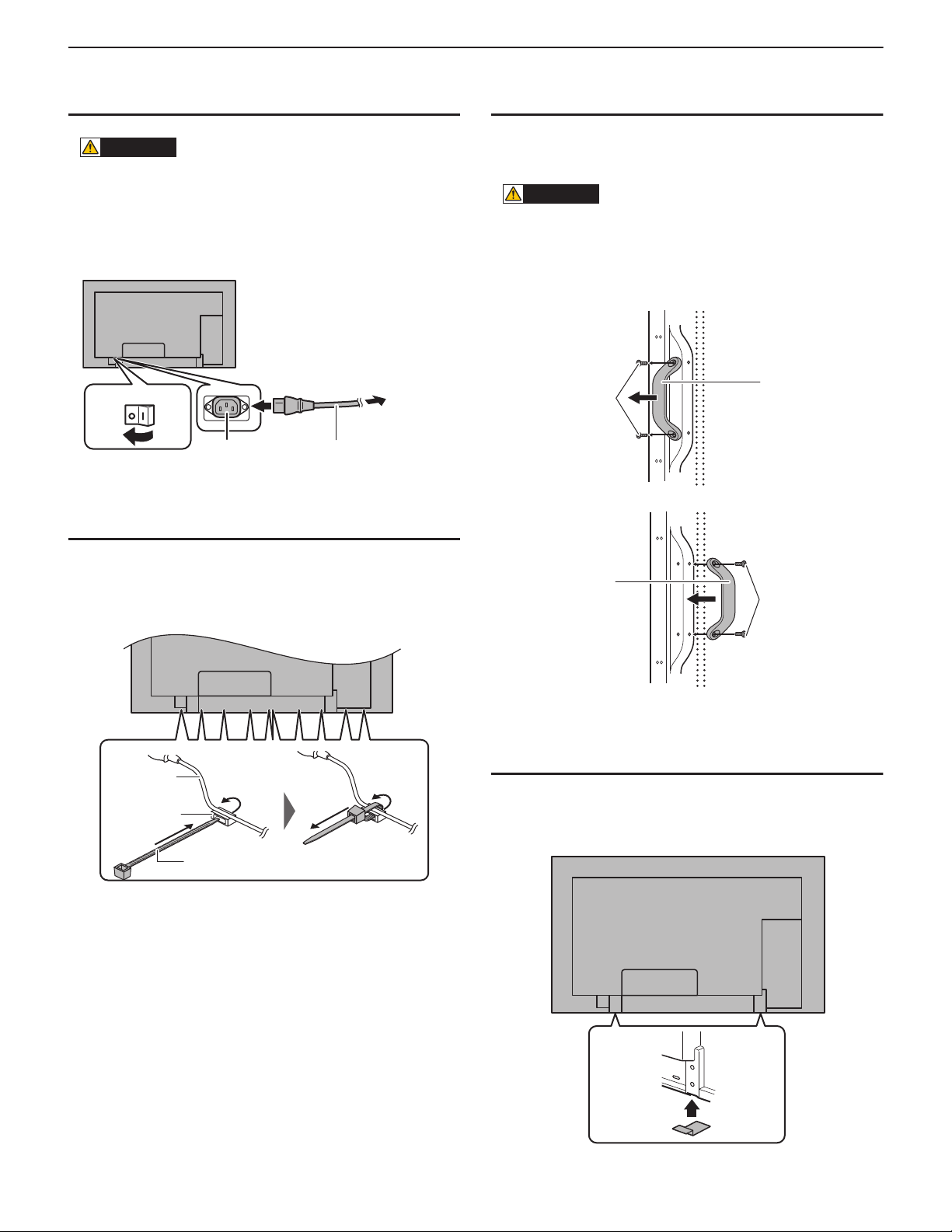
1 - 2. CONNECTING THE POWER CORD
CAUTION
n
Do not use a power cord other than the one supplied with the
monitor.
1 ) Turn off the main power switch.
2 ) Plug the power cord (supplied) into the AC input terminal.
3 ) Plug the power cord (supplied) into the AC power outlet.
1 - 3. BINDING CABLES
1 - 4. REMOVING THE HANDLES
n
The handles can be removed.
n
The removed handles can be attached on the rear side.
CAUTION
n
The removed handles and handle screws are for use with this
monitor. Do not use them for any other devices.
n
To attach handles, be sure to use the handles and handle screws
which were removed from the monitor.
Be sure the handles are attached securely.
Handle
Handle screws
The cables connected to the terminals on the rear of the monitor can be
fastened with the supplied cable clamp.
Insert the cable clamp into the cable clamp attachment on the rear of
the monitor and fasten the cables.
Cable
Cable clamp
attachment
Cable clamp
Handle
Handle screws
1 - 5. AFFIXING THE STAND HOLE
PROTECTION COVERS
After installing the monitor, affix the stand hole protection covers as
necessary.
1 ) Peel off the backing sheet and affix the cover on the monitor.
PN-E601 INSTALLATION, ADJUSTMENT, SETTING
2 – 6
Page 24
CHAPTER 2. INSTALLATION, ADJUSTMENT, SETTING
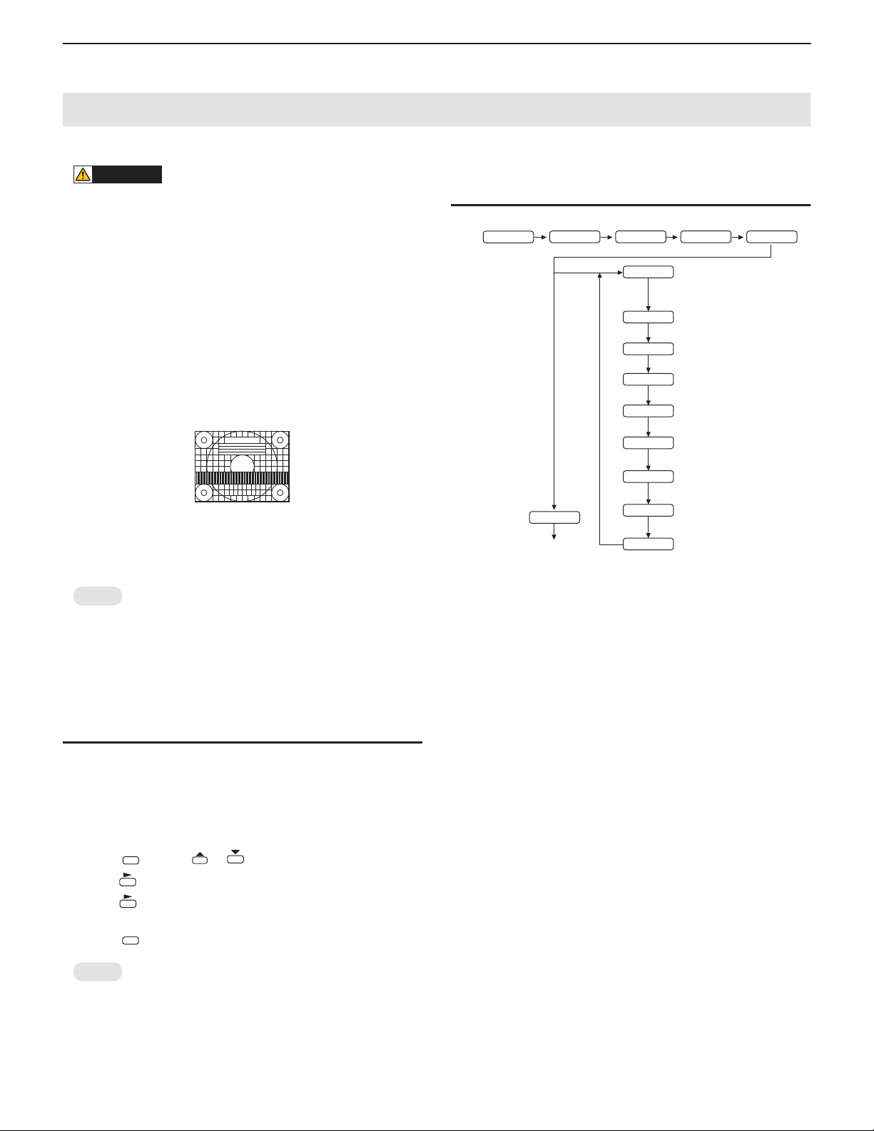
2. ADJUSTMENT
CAUTION
SCREEN DISPLAY FOR ADJUSTMENT
n
Before making adjustments in the SCREEN menu or PICTURE
menu, display an image to brighten the entire screen. If you are
using a Windows PC, use the adjustment pattern on the supplied
CD-ROM.
OPENING THE ADJUSTMENT PATTERN
The following example is performed in Windows XP.
1 ) Load the supplied CD-ROM into the computer’s CD-ROM drive.
2 ) Open the CD-ROM in [My Computer].
3 ) Double-click [Adj_uty.exe].
The adjustment pattern will appear.
Adjust the screen automatically or manually.
4 ) When adjustment is finished, press the [Esc] on the computer’s
keyboard to quit the adjustment program.
5 ) Eject the CD-ROM from the CD-ROM drive.
MEMO
n
If the display mode on the computer you are using is 65,000 colors, the color levels in the color pattern may appear differently or
grayscale may appear to be colored.
(This is due to the specifications of the input signal and is not a
malfunction.)
2 - 1. AUTOMATIC ADJUSTMENT
When you use the PC D-SUB input terminal or PC RGB input terminals
to display a PC screen for the first time, or when you change the setting
of the PC, use the automatic screen adjustment.
1 ) Switch the input to PC D-SUB or to PC RGB and display the adjust-
ment pattern. (See the description above.)
2 ) Press and use or to display the SCREEN menu.
3 ) Press and select “AUTO”.
4 ) Press .
5 ) Press twice to close the menu screen.
MENU
The automatic adjustment is complete in several seconds.
MENU
2 - 2. INITIALIZATION (RESET)/FUNC-
TIONAL RESTRICTION SETTING
SIZE
(Press about 5 seconds.)
MENU
END
*1 Resets all the settings to the factory default settings.
When the unit is without PN-ZB01(optional), “ALL RESET” is displayed.
2 Returns all settings to the factory default settings except for the
following items.
LAN SETUP, RS-232C/LAN SELECT, ID No. SET, BAUD RATE,
NETWORK, MAIL, SERVICE & SUPPORT, and SNMP
When the unit is equipped with PN-ZB01 (optional), you can
make selections.
NOTE FOR EXECUTING “ALL RESET 1”
n
Since the setting values related to LAN are initialized, do not use
in an environment with LAN.
n
When executing “ALL RESET 1” under the connected network
environment, be sure to disconnect the LAN cable before exec ution.
(This is because the operation is slowed and failed if there are
two or more sets of the initial state of IP address in a same network.)
ALL RESET
(ALL RESET1
ALL RESET2
ADJUSTMENT LOCK
(Adjust with
RS-232C/LAN
(Adjust with
OSD DISPLAY
(Adjust with
LED
(Adjust with
TEMPERATURE ALERT
(Adjust with
STATUS ALERT
(Adjust with
POWER BUTTON
(Adjust with
CONTROLLER INPUT
(Adjust with
*1
/
*2
)
e and d.)
e and d.)
e and d.)
e and d.)
e and d.)
e and d.)
e and d.)
e and d.)
MEMO
n
If the screen cannot be adjusted properly with one automatic
adjustment, repeat the automatic adjustment two or three times.
Try manual adjustment if necessary.
PN-E601 INSTALLATION, ADJUSTMENT, SETTING
2 – 7
Page 25
CHAPTER 2. INSTALLATION, ADJUSTMENT, SETTING
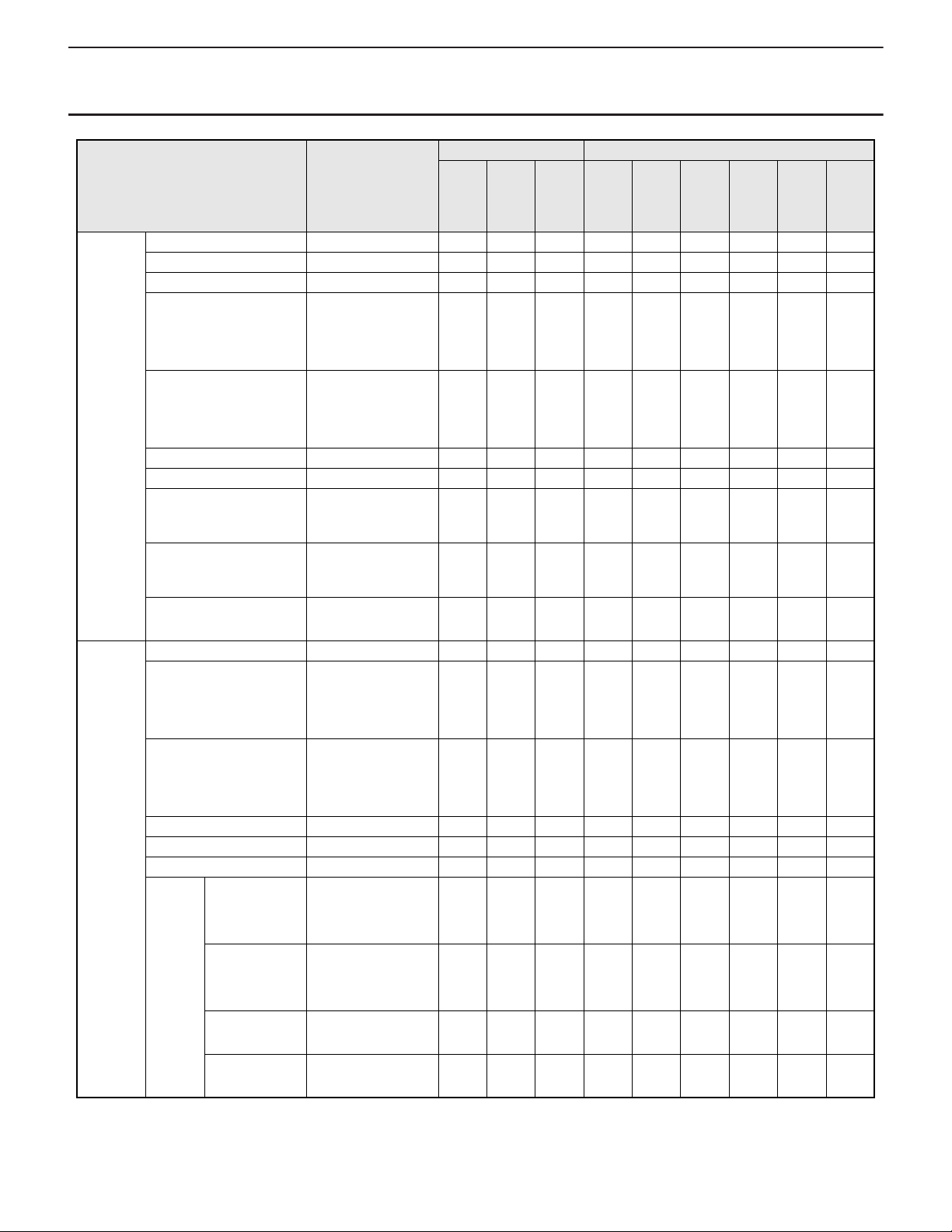
2 - 3. ADJUSTMENT ITEM LIST
PN-E601 PN-ZB01
AV
ITEM ADJUSTMENT
SCREEN AUTO ¥¥
CLOCK 0 - 1200 ¥¥
PHASE 0 - 63 ¥¥
H-POS PC D-SUB/PC RGB :
0 - 800
PC DVI-D/PC HDMI/
AV : 0 - 100
V-POS PC D-SUB/PC RGB :
0 - 200
PC DVI-D/PC HDMI/
AV : 0 - 100
H-SIZE 0 - 100 ¥¥¥¥¥¥¥¥¥
V-SIZE 0 - 100 ¥¥¥¥¥¥¥¥¥
H-RESOLUTION 300 - 1920
(Only as for the even
number)
V-RESOLUTION 200 - 1200
(Only as for the even
number)
RESET OFF
ON
PICTURE AUTO ¥¥
CONTRAST PC DVI-D/PC HDMI/
AV : 0 - 60
PC D-SUB/PC RGB :
0 - 127
BLACK LEVEL PC DVI-D/PC HDMI/
AV : 0 - 60
PC D-SUB/PC RGB :
0 - 127
TINT 0 - 60 ¥¥¥¥¥¥¥¥¥
COLORS 0 - 60 ¥¥¥¥¥¥¥¥¥
SHARPNESS 0 - 24 ¥¥¥¥¥¥¥¥¥
ADVAN
CED
FLESH TONE OFF
LOW
HIGH
3D-NR OFF
LOW
HIGH
MPEG-NR OFF
ON
3D-Y/C OFF
ON
PC
D-SUBPCHDMIAVHDMIPCDVI-DPCRGBAVDVI-D
¥¥¥¥¥¥¥¥¥
¥¥¥¥¥¥¥¥¥
¥¥
¥¥
¥¥¥¥¥¥¥¥¥
¥¥¥¥¥¥¥¥¥
¥¥¥¥¥¥¥¥¥
¥ ¥¥¥¥
¥ ¥¥¥¥
¥ ¥¥¥¥
COM-
PONE
NT
AV
S-
VIDEO
AV
VIDEO
¥
PN-E601 INSTALLATION, ADJUSTMENT, SETTING
2 – 8
Page 26

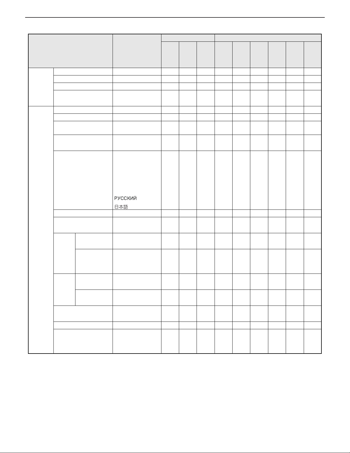
CHAPTER 2. INSTALLATION, ADJUSTMENT, SETTING
ITEM ADJUSTMENT
PICTURE ADVAN
CED
COLOR MODE STD
WHITE BALANCE THRU (Only PC DVI-
PRESET 3000K - 10000K
R-CONTRAST 0 - 256 ¥¥¥¥¥¥¥¥¥
G-CONTRAST 0 - 256 ¥¥¥¥¥¥¥¥¥
B-CONTRAST 0 - 256 ¥¥¥¥¥¥¥¥¥
COPY TO USER OFF
GAMMA 1.8
RESET OFF
C.M.S.HUE
C.M.S.SATURATION
C.M.S.VALUE
R -10 - 0 - +10 ¥ ¥¥¥¥
Y -10 - 0 - +10 ¥ ¥¥¥¥
G -10 - 0 - +10 ¥ ¥¥¥¥
C -10 - 0 - +10 ¥ ¥¥¥¥
B -10 - 0 - +10 ¥ ¥¥¥¥
M -10 - 0 - +10 ¥ ¥¥¥¥
RE
OFF
SET
ON
R -10 - 0 - +10 ¥ ¥¥¥¥
Y -10 - 0 - +10 ¥ ¥¥¥¥
G -10 - 0 - +10 ¥ ¥¥¥¥
C -10 - 0 - +10 ¥ ¥¥¥¥
B -10 - 0 - +10 ¥ ¥¥¥¥
M -10 - 0 - +10 ¥ ¥¥¥¥
RE
OFF
SET
ON
R -10 - 0 - +10 ¥ ¥¥¥¥
Y -10 - 0 - +10 ¥ ¥¥¥¥
G -10 - 0 - +10 ¥ ¥¥¥¥
C -10 - 0 - +10 ¥ ¥¥¥¥
B -10 - 0 - +10 ¥ ¥¥¥¥
M -10 - 0 - +10 ¥ ¥¥¥¥
RE
OFF
SET
ON
VIVID
sRGB (Only PC)
D/PC HDMI)
PRESET
USER
(500K carve),
5600, 9300
ON
2.0
2.2
2.4
USER
(OPTION)
ON
PC
D-SUBPCHDMIAVHDMIPCDVI-DPCRGBAVDVI-D
¥¥¥¥¥¥¥¥¥
¥¥¥¥¥¥¥¥¥
¥¥¥¥¥¥¥¥¥
¥¥¥¥¥¥¥¥¥
¥¥¥¥¥¥¥¥¥
¥¥¥¥¥¥¥¥¥
PN-E601 PN-ZB01
COMPONE
¥ ¥¥¥¥
¥ ¥¥¥¥
¥ ¥¥¥¥
AV
NT
AV
S-
VIDEO
AV
VIDEO
PN-E601 INSTALLATION, ADJUSTMENT, SETTING
2 – 9
Page 27
CHAPTER 2. INSTALLATION, ADJUSTMENT, SETTING
PN-E601 PN-ZB01
ITEM ADJUSTMENT
PC
D-SUBPCHDMIAVHDMIPCDVI-DPCRGBAVDVI-D
COMPONE
NT
AUDIO TREBLE -5 - 0 - +5 ¥¥¥¥¥¥¥¥¥
BASS -5 - 0 - +5 ¥¥¥¥¥¥¥¥¥
BALANCE -10 - 0 - +10 ¥¥¥¥¥¥¥¥¥
AV
RESET OFF
ON
¥¥¥¥¥¥¥¥¥
SETUP OSD H-POSITION 0 - 100 ¥¥¥¥¥¥¥¥¥
OSD V -POSITION 0 - 100 ¥¥¥¥¥¥¥¥¥
MONITOR LANDSCAPE
PORTRAIT
MONAURAL AUDIO OFF
ON
¥¥¥¥¥¥¥¥¥
¥¥¥¥¥¥¥¥¥
LANGUAGE ENGLISH
DEUTSCH
FRANCAIS
ITALIANO
¥¥¥¥¥¥¥¥¥
ESPAÑOL
AV
S-
VIDEO
AV
VIDEO
POWER ON DELAY 0 - 60S ¥¥¥¥¥¥¥¥¥
STANDB Y MODE STANDARD
LOW POWER
HDMI
SETTING
HDMI AUTO
VIEW
HDMI RGB
INPUT RANGE
OFF
ON
AUTO
FULL
¥¥¥¥¥¥¥¥¥
¥¥¥¥¥¥¥¥¥
¥¥¥¥¥¥¥¥¥
LIMITED
HOT
PLUG
CONTROL
RS-232C/LAN SELECT RS-232C
HDMI OFF
ON
DVI OFF
ON
LAN
¥¥¥¥¥¥¥¥¥
¥¥¥¥¥¥¥¥¥
¥¥¥¥¥¥¥¥¥
ID No. SET 0 - 255 ¥¥¥¥¥¥¥¥¥
BAUD RATE 9600bps
19200bps
¥¥¥¥¥¥¥¥¥
38400bps
PN-E601 INSTALLATION, ADJUSTMENT, SETTING
2 – 10
Page 28

CHAPTER 2. INSTALLATION, ADJUSTMENT, SETTING
ITEM ADJUSTMENT
SETUP LAN
SETUP
(When
the unit is
equipped
with
PN-ZB01
(optional)
, you can
make
selections.)
SPEAKER SELECT
(When the unit is equipped
with PN-ZB01 (optional),
you can make selections.)
OPTION DC OUT
SETTING
OPTION DATE/TIME
SETTING
SCHEDULE
DHCP CLIENT OFF
ON
IP ADDRESS Input the address ¥¥¥¥¥¥¥¥¥
SUBNET MASK Input the address ¥¥¥¥¥¥¥¥¥
DEFAULT
Input the address
GATEWAY
RESET OFF
ON
INTERNAL
EXTERNAL
OFF
MODE1
MODE2
Year : 2009 - 2099 ¥¥¥¥¥¥¥¥¥
Month : 1 - 12 ¥¥¥¥¥¥¥¥¥
Day : 1 - 28, 29, 30,
31
Time : 00:00 - 23:59 ¥¥¥¥¥¥¥¥¥
(Set --- or ¥) ¥ (Invalidity)
--- (Effectriely)
POWER ON
OFF
DAY OF THE
WEEK
ONLY ONCE
EVERY WEEK
EVERY DAY
SUN MON
TUE WED
THU FRI
SAT
--- SUN
MON TUE
WED THU
FRI SAT
TIME 00:00 - 23:59 ¥¥¥¥¥¥¥¥¥
INPUT ---
DVI-D
HDMI
D-SUB
BNC
S-VIDEO
VIDEO
PC
D-SUBPCHDMIAVHDMIPCDVI-DPCRGBAVDVI-D
¥¥¥¥¥¥¥¥¥
¥¥¥¥¥¥¥¥¥
¥¥¥¥¥¥¥¥¥
¥¥¥¥¥¥¥¥¥
¥¥¥¥¥¥¥¥¥
¥¥¥¥¥¥¥¥¥
¥¥¥¥¥¥¥¥¥
¥¥¥¥¥¥¥¥¥
¥¥¥¥¥¥¥¥¥
¥¥¥¥¥¥¥¥¥
¥¥¥¥¥¥¥¥¥
¥¥¥¥¥¥¥¥¥
PN-E601 PN-ZB01
COMPONE
AV
NT
AV
S-
VIDEO
AV
VIDEO
PN-E601 INSTALLATION, ADJUSTMENT, SETTING
2 – 11
Page 29

CHAPTER 2. INSTALLATION, ADJUSTMENT, SETTING
ITEM ADJUSTMENT
OPTION INPUT
SELECT
AUDIO
SELECT
DVI
(When the unit
PC DVI-D
AV DVI-D
is equipped with
PN-ZB01
(optional), you
can make
selections.)
BNC
(When the unit
PC RGB
AV COMPONENT
is equipped with
PN-ZB01
(optional), you
can make
selections.)
HDMI PC HDMI
AV HDMI
PC DVI-D AUDIO
AUDIO1
AUDIO2
PC HDMI [Only Display]
HDMI
AUDIO
[Only when the unit is
equipped with
PN-ZB01.]
HDMI
AUDIO
AUDIO1
AUDIO2
PC D-SUB
(When the unit
is equipped with
PN-ZB01
AUDIO
AUDIO1
AUDIO2
(optional), you
can make
selections.)
PC RGB
(When the unit
is equipped with
PN-ZB01
AUDIO
AUDIO1
AUDIO2
(optional), you
can make
selections.)
AV DVI -D
(When the unit
is equipped with
PN-ZB01
AUDIO
AUDIO1
AUDIO2
(optional), you
can make
selections.)
PC
D-SUBPCHDMIAVHDMIPCDVI-DPCRGBAVDVI-D
¥¥¥¥¥¥¥¥¥
¥¥¥¥¥¥¥¥¥
¥¥¥¥¥¥¥¥¥
¥¥¥¥¥¥¥¥¥
¥¥¥¥¥¥¥¥¥
¥¥¥¥¥¥¥¥¥
¥¥¥¥¥¥¥¥¥
¥¥¥¥¥¥¥¥¥
PN-E601 PN-ZB01
COMPONE
AV
NT
AV
S-
VIDEO
AV
VIDEO
PN-E601 INSTALLATION, ADJUSTMENT, SETTING
2 – 12
Page 30

CHAPTER 2. INSTALLATION, ADJUSTMENT, SETTING
ITEM ADJUSTMENT
OPTION AUDIO
SELECT
INPUT
SIGNAL
SCAN MODE MODE1
POWER MANAGEMENT OFF
AV HDMI HDMI
AUDIO
AV HDMI
(When the unit
is equipped with
PN-ZB01
(optional), you
HDMI
AUDIO
AUDIO1
AUDIO2
can make
selections.)
AV COMPONENT
(When the unit
is equipped with
AUDIO
AUDIO1
AUDIO2
PN-ZB01
(optional), you
can make
selections.)
AV S-VIDEO
(When the unit
is equipped with
PN-ZB01
AUDIO
AUDIO1
AUDIO2
(optional), you
can make
selections.)
AV VIDEO
(When the unit
is equipped with
PN-ZB01
AUDIO
AUDIO1
AUDIO2
(optional), you
can make
selections.)
480 LINES AUTO
640 x 480
848 x 480
768 LINES AUTO
1024 x 768
1280 x 768
1360 x 768
(1366 x 768)
1050 LINES 1400 x 1050
1680 x 1050
ZOOM2 SPECIAL SETTING
OFF
ON
MODE2
MODE3
ON
PC
D-SUBPCHDMIAVHDMIPCDVI-DPCRGBAVDVI-D
¥¥¥
¥¥¥¥¥¥¥¥¥
¥¥¥¥¥¥¥¥¥
¥¥¥¥¥¥¥¥¥
¥¥¥¥¥¥¥¥¥
¥¥
¥¥
¥¥
¥¥
¥¥¥¥¥¥¥¥¥
PN-E601 PN-ZB01
COMPONE
¥ ¥¥¥¥
AV
NT
AV
S-
VIDEO
AV
VIDEO
PN-E601 INSTALLATION, ADJUSTMENT, SETTING
2 – 13
Page 31

CHAPTER 2. INSTALLATION, ADJUSTMENT, SETTING
PN-E601 PN-ZB01
ITEM ADJUSTMENT
OPTION COLOR SYSTEM AUTO
PAL
PAL-60
SECAM
NTSC3.58
NTSC4.43
AUDIO OUTPUT VARIABLE
FIXED
AUDIO INPUT LEVEL 1.0Vrms
0.5Vrms
SELF ADJUST OFF
ON
AUTO INPUT CHANGE OFF
ON
DOUBLE SPEED DRIVE OFF
ON
BACKLIGHT OFF OFF
ON
ENLARGEENLARGE H 1 - 5 ¥¥ ¥¥
ENLARGE V 1 - 5 ¥¥ ¥¥
ENLARGE-PO S H 1 - 5 ¥¥ ¥¥
ENLARGE-PO S V 1 - 5 ¥¥ ¥¥
BEZEL H 0 - 100 ¥¥ ¥¥
BEZEL V 0 - 100 ¥¥ ¥¥
H-POS Depend on setting ¥¥ ¥¥
V-POS Depend on setting ¥¥ ¥¥
PIP/PbyP PIP MODES
(PC HDMI: Only when the
unit is equipped with
PN-ZB01.)
OFF
PIP
PbyP
PbyP2
PIP SIZE
1 - 12
(PC HDMI: Only when the
unit is equipped with
PN-ZB01.)
PIP H-POS
0 - 100
(PC HDMI: Only when the
unit is equipped with
PN-ZB01.)
PIP V-POS
0 - 100
(PC HDMI: Only when the
unit is equipped with
PN-ZB01.)
PIP BLEND
0 - 15
(PC HDMI: Only when the
unit is equipped with
PN-ZB01.)
PC
D-SUBPCHDMIAVHDMIPCDVI-DPCRGBAVDVI-D
¥¥¥¥¥¥¥¥¥
¥¥¥¥¥¥¥¥¥
¥¥¥¥¥¥¥¥¥
¥¥¥¥¥¥¥¥¥
¥¥¥¥¥¥¥¥¥
¥¥¥¥¥¥¥¥¥
¥¥¥¥¥¥¥¥¥
¥¥¥¥¥¥¥¥¥
¥¥¥¥¥¥¥¥¥
¥¥¥¥¥¥¥¥¥
¥¥¥¥¥¥¥¥¥
AV
COMPONE
NT
AV
VIDEO
AV
S-
VIDEO
¥¥
PN-E601 INSTALLATION, ADJUSTMENT, SETTING
2 – 14
Page 32

CHAPTER 2. INSTALLATION, ADJUSTMENT, SETTING
MEMO
ITEM ADJUSTMENT
PIP/PbyP PIP SOURCE
(When the unit is equipped
with PN-ZB01 (optional),
you can make selections.)
SOUND CHANGE
(PC HDMI: Only when the
unit is equipped with
PN-ZB01.)
MAIN POS
(PC HDMI: Only when the
unit is equipped with
PN-ZB01.)
PbyP2 POS
(PC HDMI: Only when the
unit is equipped with
PN-ZB01.)
AUTO OFF
(PC HDMI: Only when the
unit is equipped with
PN-ZB01.)
MAIN
SUB
POS1
POS2
POS1
POS2
POS3
MANUAL
AUTO
PC
D-SUBPCHDMIAVHDMIPCDVI-DPCRGBAVDVI-D
¥¥¥¥¥¥¥¥¥
¥¥¥¥¥¥¥¥¥
¥¥¥¥¥¥¥¥¥
¥¥¥¥¥¥¥¥¥
¥¥¥¥¥¥¥¥¥
PN-E601 PN-ZB01
COMPONE
AV
NT
AV
S-
VIDEO
AV
VIDEO
n
When “WHITE BALANCE” is set to “THRU,” “BLACK LEVEL,” “CONTRAST” and “GAMMA” cannot be configured.
n
When “COLOR MODE” is set to “sRGB” and “VIVID,” the following items cannot be configured.
“WHITE BALANCE,” “PRESET,” “R/G/B-CONT RAS T,” “CO PY TO USER” and “G AM MA ”
PN-E601 INSTALLATION, ADJUSTMENT, SETTING
2 – 15
Page 33

CHAPTER 2. INSTALLATION, ADJUSTMENT, SETTING
2 - 4. ADJUSTMENT ITEM DEFAULT V ALUE LIST
ITEM DEFAULT
SCREEN AUTO
CLOCK 600
PHASE 31
H-POS PC D-SUB/PC RGB: It varies depending on the signal.
V-POS PC D-SUB/PC RGB: It varies depending on the signal.
H-SIZE 50
V-SIZE 50
H-RESOLUTION It varies depending on the signal.
V-RESOLUTION It varies depending on the signal.
RESET OFF
PICTURE AUTO
CONTRAST PC DVI-D/P C HDMI/AV: 30
BLACK LEVEL PC DVI-D/PC HDMI/AV: 30
TINT 30
COLORS 30
SHARPNESS 12
ADVANCED FLESH TONE OFF
3D-NR LOW
MPEG-NR OFF
3D-Y/C ON
C.M.S.-HUE R 0
Y0
G0
C0
B0
M0
RESET OFF
C.M.S.-SATURATION R 0
Y0
G0
C0
B0
M0
RESET OFF
C.M.S.-VALUE R 0
Y0
G0
C0
B0
M0
RESET OFF
COLOR MODE STD
WHITE BALANCE PRESET
PRESET 9000
R-CONTRAST 256
G-CONTRAST 256
PC DVI-D/PC HDMI/AV: 50
PC DVI-D/PC HDMI/AV: 50
PC D-SUB/PC RGB: It varies depending on the main unit.
PC D-SUB/PC RGB: It varies depending on the main unit.
PN-E601 INSTALLATION, ADJUSTMENT, SETTING
2 – 16
Page 34

CHAPTER 2. INSTALLATION, ADJUSTMENT, SETTING
ITEM DEFAULT
PICTURE B-CONTRAST 256
COPY TO USER OFF
GAMMA 2.2
RESET OFF
AUDIO TREBLE 0
BASS 0
BALANCE 0
RESET OFF
SETUP OSD H-POSITION 50
OSD V-POSITION 50
MONITOR LANDSCAPE
MONAURAL AUDIO OFF
LANGUAGE ENGLISH
POWER ON DELAY 0S
STAN DBY MODE STAN DARD
HDMI SETTING HDMI AUTO VIEW ON
HDMI RGB INPUT RANGE AUTO
HOT PLUG CONTROL HDMI ON
DVI ON
RS-232C/LAN SELECT RS-232C
ID No. SET 0
BAUD RATE 9600 bps
LAN SETUP DHCP CLIENT OFF
IP ADDRESS 192. 168. 150. 2
SUBNET MASK 255. 255. 255. 0
DEFAULT GATEWAY 0. 0. 0. 0
RESET OFF
SPEAKER SELECT INTERNAL
OPTION DC OUT SETTING OFF
OPTION DATE/TIME SETTING 2009/1/1 0:00
SCHEDULE (Set --- or \) ---
POWER ---
DAY OF THE W EEK ---
TIME ---
INPUT --INPUT SELECT DVI PC DVI-D
BNC AV CO MPONENT
HDMI AV HDMI
AUDIO SELECT PC DVI-D AUDIO
PC HDMI HDMI
PC D-SUB AUDIO
PC RGB AUDIO
AV DVI-D AUDIO1
AV HDMI HDMI
AV COMPONENT AUDIO2
AV S-VIDEO AUDIO2
AV VIDEO AUDIO2
INPUT SELECT 480 LINES AUTO
768 LINES AUTO
1050 LINES 1400 x 1050
ZOOM2 SPECIAL SETTING OFF
PN-E601 INSTALLATION, ADJUSTMENT, SETTING
2 – 17
Page 35

CHAPTER 2. INSTALLATION, ADJUSTMENT, SETTING
ITEM DEFAULT
OPTION SCAN MODE MODE1
POWER MANAGEMENT PC : ON
A V : OFF
COLOR SYSTEM AUTO
AUDIO OUTPUT VARIABLE
AUDIO INPUT LEVEL 0.5 Vrms
SELF ADJUST ON
AUTO INPUT CHANGE OFF
DOUBLE SPEED DRIVE PC : ON
A V : ON
BACKLIGHT OFF OFF
ENLARGE ENLARGE H 1
ENLARGE V 1
ENLARGE-POS H 1
ENLARGE-POS V 1
BEZEL H 50
BEZEL V 50
H-POS 0
V-POS 0
PIP/PbyP PIP MODES OFF
PIP SIZE 11
PIP H-POS 99
PIP V-POS 1
PIP BLEND 0
PIP SOURCE [Only display]
PC : AV HDMI [Fixed]
A V : PC D-SU B [Fixed]
[Add PN-ZB01]
PC : AV VIDEO
A V : PC D-SUB
SOUND CHANGE MAIN
MAIN POS POS1
PbyP2 POS POS2
AUTO OFF AUTO
PN-E601 INSTALLATION, ADJUSTMENT, SETTING
2 – 18
Page 36

CHAPTER 2. INSTALLATION, ADJUSTMENT, SETTING
(Adjust with e and d.)
(Adjust with
e and d.)
(Adjust with
e and d.)
(Adjust with
e and d.)
(Adjust with
e and d.)
(Initialize with
d.)
(Adjust with
e and d.)
(Adjust with
e and d.)
(Adjust with
e and d.)
(Adjust with
e and d.)
(Adjust with
e and d.)
(Adjust with
e and d.)
(Adjust with
e and d.)
(Adjust with
e and d.)
(Adjust with
d.)
(Adjust with
e and d.)
(Adjust with
e and d.)
(Adjust with
e and d.)
AUTO (PC D-SUB/PC RGB)
CLOCK (PC D-SUB/PC RGB)
PHASE (PC D-SUB/PC RGB)
H-POS
V-POS
(Adjust with e and d.)
(Adjust with
e and d.)
(Adjust with
e and d.)
(Adjust with
e and d.)
H-SIZE
V-SIZE
H-RESOLUTION (PC D-SUB/PC RGB)
V-RESOLUTION (PC D-SUB/PC RGB)
RESET
SCREEN
PICTURE
AUTO (PC D-SUB/PC RGB)
CONTRAST
BLACK LEVEL
TINT
COLORS
SHARPNESS
ADVANCED (AV input)
COLOR MODE
WHITE BALANCE
(THRU /PRESET/USER)
R-CONTRAST
G-CONTRAST
B-CONTRAST
COPY TO USER
GAMMA
RESET
*1 sRGB is PC input only.
*2 For PC DVI-D/PC HDMI only
(Initialize with
d.)
MENU
MENU
END
AB
*2
*1
PRESET
(Adjust with e and d.)
AUDIO
TREBLE
BASS
BALANCE
RESET
(Adjust with e and d.)
(Adjust with
e and d.)
(Adjust with
e and d.)
(Initialize with
d.)
2 - 5. SETTINGS AND ADJUSTMENTS
PN-E601 INSTALLATION, ADJUSTMENT, SETTING
2 – 19
Page 37

CHAPTER 2. INSTALLATION, ADJUSTMENT, SETTING
SETUP
OSD H-POSITION
OSD V-POSITION
MONITOR
MONAURAL AUDIO
LANGUAGE
HDMI SETTING
HOT PLUG CONTROL
POWER ON DELAY
STANDBY MODE
OPTION
DATE/TIME SETTING
SCHEDULE
INPUT SELECT
(DVI/BNC/HDMI)
AUDIO SELECT
SCAN MODE (AV input)
POWER MANAGEMENT
COLOR SYSTEM
(AV S-VIDEO/AV VIDEO)
SELF ADJUST
AUDIO OUTPUT
AUDIO INPUT LEVEL
AUTO INPUT CHANGE
DOUBLE SPEED DRIVE
(Adjust with e and d.)
(Adjust with
e and d.)
(Adjust with
e and d.)
(Adjust with
e and d.)
(Adjust with
e and d.)
(Adjust with
e and d.)
(Adjust with
e and d.)
(Adjust with
e and d.)
(Adjust with
e and d.)
RS-232C/LAN SELECT
(Adjust with e and d.)
OPTION DC OUT SETTING
(Adjust with e and d.)
ID No. SET
BAUD RATE
LAN SETUP
SPEAKER SELECT
(Adjust with e and d.)
(Adjust with
e and d.)
(Adjust with
e and d.)
(Adjust with
e and d.)
(Adjust with
e and d.)
(Adjust with
e and d.)
(Adjust with
e and d.)
(Adjust with
e and d.)
(Adjust with
e and d.)
(Adjust with
e and d.)
(Adjust with
e and d.)
(Adjust with
e and d.)
(Adjust with
e and d.)
(Adjust with
e and d.)
(Adjust with
e and d.)
(Adjust with
e and d.)
(Adjust with
e and d.)
A
INPUT SIGNAL
(PC D-SUB/PC RGB)
(480 LINES/768 LINES/
1050 LINES/ZOOM2 SPECIAL
SETTING)
C
(Only when the unit is
equipped with PN-ZB01.)
(Only when the unit is
equipped with PN-ZB01.)
PN-E601 INSTALLATION, ADJUSTMENT, SETTING
2 – 20
Page 38

CHAPTER 2. INSTALLATION, ADJUSTMENT, SETTING
PIP/PbyP
PIP SIZE
PIP H-POS
PIP V-POS
PIP BLEND
PIP SOURCE
SOUND CHANGE
MAIN POS
PbyP2 POS
AUTO OFF
PIP MODES
(Adjust with e and d.)
(Adjust with
e and d.)
(Adjust with
e and d.)
(Adjust with
e and d.)
(Adjust with
e and d.)
(Adjust with
e and d.)
(Adjust with
e and d.)
(Adjust with
e and d.)
(Adjust with
e and d.)
(Adjust with
e and d.)
* The menu screen will close automatically if no operation is performed for about 15 seconds.
B
C
ENLARGE
(PC input)
ENLARGE H
ENLARGE V
ENLARGE-POS H/
ENLARGE-POS V
BEZEL H / BEZEL V
H-POS
V-POS
(Adjust with e and d.)
(Adjust with
e and d.)
(Adjust with
e and d.)
(Adjust with
e and d.)
(Adjust with
e and d.)
(Adjust with
e and d.)
PN-E601 INSTALLATION, ADJUSTMENT, SETTING
2 – 21
Page 39

CHAPTER 2. INSTALLATION, ADJUSTMENT, SETTING
SCHEDULE
No. POWER DAY OF THE WEEK TIME INPUT
XXXX/XX/XX XXX XX:XX:XX
OK…[MENU]
1920x1080
V: 60 Hz H: 66.3 kHz
PC D-SUB
MENU
3. SETTING
3 - 1. SCHEDULE
You can set the time to switch the monitor on and off.
Set this function with “SCHEDULE” in the OPTION menu.
1 ) Press or to select the SCHEDULE number, and press .
2 ) Set the SCHEDULE. (See the description below.)
Press or to select items, and press or to change
the setting.
3 ) Press .
SCHEDULE becomes effective.
No.
POWER
DAY OF
THE
WEEK
TIME
INPUT
SCHEDULE effective
-
SCHEDULE not effective
ON Switches the monitor on at the specified time.
OFF Switches the monitor off at the specified time
and puts the monitor in standby mode.
Specifies the day of the week to e x ecute the SCHEDULE.
ONLY
ONCE
Executes the SCHEDULE once on the specified day.
Specify the day of the week to execute the
SCHEDULE.
EVERY
WEEK
Executes the SCHEDULE on the specified
day of the week every week. Specify the day
of the week to execute the SCHEDULE.
Periodic setting such as “Monday through
Friday” is also possible.
EVERY
Executes the SCHEDULE every day regard-
DAY
less of the day of the week.
Specifies the time to execute the SCHEDULE.
Set the time on a 24-hour basis.
Specifies the input mode at power-on. When not specifying, the screen at the previous power-off appears.
n
Input modes displayed on “DVI” depend on “DVI
SELECT” settings.
n
Input modes displayed on “HDMI” d epend on “ HDMI
SELECT” settings.
n
Input modes displayed on “BNC” depend on “BNC
SELECT” settings.
CAUTION
n
Do not switch off the main power after setting the SCHEDULE.
n
Specify the correct date and time.
SCHEDULE does not function unless the date and time are specified.
n
Check regularly that the set date and time are correct.
n
When “STANDBY MODE” is “LOW POWE R”, SCHEDULE cannot be set.
MEMO
n
Up to 8 SCHEDULE items can be registered.
n
Setting the SCHEDULE flashes the power LED alternately in red
and orange in standby mode.
n
A SCHEDULE that has a large number has precedence over that
of a small number when schedules overlap.
3 - 2. ADVANCED ITEMS (AV INPUT)
ITEM CONTENT
FLESH TONE Adjust the hue control.
3D-NR Reduce the noise of playback images on video.
Setting a higher level reduces more noise.
However, it may cause blurring on an image.
MPEG-NR Reduce block noise caused by digital compres-
3D-Y/C
(AV AUDIO)
C.M.S.-HUE Adjusts color tone with 6 colors of R (red),
C.M.S.-SATURATION
C.M.S.-VALUE Adjusts color br ightnes s with 6 c olors of R (red),
MEMO
n
When “FLESH TONE” is set to “LOW” or “HI GH”, “C.M.S.-HUE/ SATURATION/-VALUE” cannot be set.
sion.
Specify whether to perform 3-dimension Y/C
separation.
If dot interference or cross-color is occurring in
fast-motion scenes, selecting “OFF” may
improve the image quality.
Y (yellow), G (green), C (cyan), B (blue), and
M (magenta).
Adjusts color vividness with 6 colors of R (red),
Y (yellow), G (green), C (cyan), B (blue), and
M (magenta).
Y (yellow), G (green), C (cyan), B (blue), and
M (magenta).
PN-E601 INSTALLATION, ADJUSTMENT, SETTING
2 – 22
Page 40

CHAPTER 3. CONTROLLING THE MONITOR WITH A PC
VOLM0030
VOLM
30
Example
Be sure to input 4 characters for the parameter.
Pad with spaces (" ") if necessary.
(" " is a return code (0D
H, 0AH or 0DH))
Wrong : VOLM30 .
Right : VOLM 30 .
AUTR-009
Example
1. RS-232C
You can control this monitor from a PC via RS-232C (COM port) on the PC.You can also connect multiple monitors via a daisy chain by using a PC.
By assigning ID numbers to each monitor, you can make input mode selection/adjustment or can check the status of a specific monitor.
1 - 1. COMMUNICATION CONDITIONS
Set the RS-232C communication settings on the PC to match the monitor’s communication settings as follows.
Set to the same baud rate as the “BAUD
Baud rate
Data length 8 bits
Parity bit None
Stop bit 1 bit
Flow control None
RATE” setting of SETUP menu.
Initial setting: 9600 bps
1 - 2. COMMUNICATION PROCEDURE (BASIC OPERATION)
■ COMMAND FORMAT
When a command is sent from the PC to the monitor, the monitor operates according to the received command and sends a response message to the PC.
C1 C2 C3 C4 P1 P2 P3 P4
Command field
(4 prescribed
alphanumerical characters)
(4 character string comprised of:
Return code
Parameter field
0-9, +, -, space, ?)
PN-E601 CONTROLLING THE MONITOR WITH A PC
When inputting a negative value, specify a numerical value in three digits.
Do not use spaces for MPOS, DATE, and SC01 through SC08.
Specify parameters using a specified number of characters.
Example
If a command has “R” listed for “DIRECTION” in the “RS-232C command table”, the current value can be returned by using “?” as the
parameter.
MPOS010097
Example
From PC to monitor.
(How much is current
volume setting?).
From monitor to PC.
(Current volume
setting: "30").
From PC to monitor
From monitor to PC.
.
3 – 1
VOLM ? ? ? ?
30
If an ID number has been assigned.
(For example, ID number : 1).
VOLM
30
001
?
Page 41

CHAPTER 3. CONTROLLING THE MONITOR WITH A PC
MEMO
Return code (0DH, 0AH)
OK
O K SPC 0 0 1
If an ID number has been assigned.
ID number of responding monitor.
Return code (0DH, 0AH)
Space (20
H)
A response is returned after a command is executed.
Return code (0DH, 0AH)
ERR
E R R SPC 001
If an ID number has been assigned.
ID number
Return code (0D
H, 0AH)Space (20H)
Return code (0DH, 0AH)
WA I T
Return code (0DH, 0AH)
LOCKED
■ RESPONSE CODE FORMAT
<WHEN A COMMAND HAS BEEN E XECUTED CORRECTLY>
<WHEN A COMMAND HAS NOT BEEN EXECUTED>
<WHEN CONTROL VIA RS-232C IS LOCKED (TO PREVENT
USE) USING THE OPERATION LOCK FUNCTION>
<WHEN “RS-232C/LAN SELECT” IS SET TO “LAN”>
Return code (0DH, 0AH)
DESNULECTE
<COMMUNICATION INTERVAL>
n
After “OK” or “ERR” is returned, you must send the following commands.
To set a timeout for the command response, specify 10 seconds or
longer.
When connecting multiple monitors in a daisy chain, set the timeout
to at least the product of the “monitor’s position from the computer
multiplied by 10 seconds”.
Example
3rd monitor from computer: 30 seconds or longer.
n
Provide an interval of 100 ms or more between the command
response and the transmission of the next command.
VOLM0020
OK
n
“ERR” is returned when there is no relevant command or when
the command cannot be used in the current state of the monitor.
n
If communication has not been established for reasons such as a
bad connection between the PC and monitor, nothing is returned
(not even “ERR”).
n
If no monitor has been assigned the designated ID number (e.g.
if the command “IDSL0002 ”is used, but no monitor with ID
number: 2 is found), no response is returned.
n
If “RS-232C/LAN COMMAND” is set to options other than “NORMAL”, the return code for a response is “0DH” only.
<IF EXECUTION OF THE COMMAND IS TAKIN G SOME TI ME>
When the following commands are used, “WAIT” is returned.
In this case, a value will be returned if you wait a while. Do not send any
command during this period.
No ID number is attached to “WAIT” response.
COMMANDS WHICH RETURN “WAIT”
n
When repeater control is used
n
When an IDSL or IDLK command is used
n
When one of the following commands is used:
RSET, INPS, ASNC, WIDE, EMAG, EPOS, PXSL, POWR, AGIN,
MWIN, MWIP, MWPP, ESTG, EMHV, EPHV, ESHV
Interval of 100 ms or more
INPS0001
WAIT
OK
MEMO
n
When executing ALL RESET, set t he timeout period to 30 seconds or longer.
n
When turning the power on while the POWER ON DELAY function is in use, set the timeout period to the POWER ON DELAY
period +10 seconds or longer.
PN-E601 CONTROLLING THE MONITOR WITH A PC
3 – 2
Page 42

CHAPTER 3. CONTROLLING THE MONITOR WITH A PC
MEMO
ID
number: 1
ID
number: 2
ID
number: 3
ID
number: 4
Example
Example
ID
number: 1
ID
number: 2
ID
number: 3
ID
number: 4
IDST001 +
WAIT
OK
001
“OK” response from ID number: 1.
OK
002
“OK” response from ID number: 2.
OK
003
“OK” response from ID number: 3.
OK
004
“OK” response from ID number: 4
(End).
ID setting command with repeater
control.
1 - 3. COMMUNICATION PROCEDURE (ADVANCED OPERATION)
This section explains commands for daisy chain connection.
The basic communication procedure is the same as in the “1 - 2. COMMUNICATION PROCEDURE (BASIC OPERATION)” section.
■ ID NUMBERS
You can assign a unique ID number to each monitor. This allows you to
control a particular monitor in a daisy chain of monitors.
You can assign ID numbers either from the menu screen (using the
remote control) or from the PC using RS-232 cable.
If monitors are connected as shown above, you can execute commands
like “Set the volume of the monitor with ID: 4 to 20”.
When controlling monitors linked in a daisy chain by designating ID
numbers, you should basically avoid any duplication of ID numbers.
ID numbers do not have to be assigned in ascending order starting from
the PC. They can also be connected as shown below.
Example
ID
number: 3
ID
number: 2
ID
number: 4
ID
number: 1
■ COMMANDS FOR ID CONTROL
The command examples shown on this page assume the following connection and ID number set up.
Example
ID
number: 1
<IDST>
A monitor receiving this command sets its own ID number in the parameter field.
Example
IDST0001
001
OK
n
You can automatically assign ID numbers by using the IDST
command with the Repeater control.
For example, using the command “IDST001+” automatically sets
the ID numbers, as shown below.
ID
number: 2
The ID number of this monitor is
set to 1.
ID
number: 3
ID
number: 4
PN-E601 CONTROLLING THE MONITOR WITH A PC
3 – 3
Page 43

CHAPTER 3. CONTROLLING THE MONITOR WITH A PC
<IDSL>
The parameter of this command sets the ID number of the monitor.
The monitor is subject to the next command.
Example
IDSL0002
WAIT
002
OK
VOLM0030
WAIT
002
OK
VOLM0020
OK
001
*1 The IDSL command is effective only once, for
the immediately succeeding command.
The next command is for the
monitor with ID number: 2.
Searching for monitor with ID
number: 2.
Found monitor with ID number: 2.
Sets volume of monitor with ID
number: 2 to 30.
Processing
OK response from monitor
with ID number: 2.
Sets volume to "20".
The volume of the monitor with
ID number: 1 (the one directly
connected to the PC) is set to
*1
"20".
<IDLK>
The parameter of this command sets the ID number of the monitor.
The monitor is subject to all subsequent commands.
<IDCK>
Provides screen display of the ID number currently assigned to a monitor, and the ID number currently set for “IDLK” (if any).
Example
(After executing IDLK0002)
IDCK0000
ID : 001 IDLK : 002
IDCK000 +
WAIT
ID : 001 IDLK : 000
ID : 002 IDLK : 000
ID : 003 IDLK : 000
ID : 004 IDLK : 000
(Parameter has no
meaning.)
Returned response.
The ID number is also
displayed on the monitor
screen.
Repeater control.
(If a command is used
with repeater control, ID
designation using "IDSL"
or "IDLK" is canceled.)
Example
IDLK0002
WAIT
002
OK
VOLM0030
WAIT
OK
002
VOLM0020
WAIT
OK
002
IDLK0000
WAIT
002
OK
VOLM0010
001
OK
*1 The IDLK command remains effective until it is
canceled, or power is shut off.
Following commands are for
the monitor with ID number: 2.
Searching for monitor with ID
number: 2.
Found monitor with ID number: 2.
Sets volume of monitor with
ID number: 2 to "30".
*1
Processing
Sets volume of monitor with
ID number: 2 to "20".
*1
Canceling fixed ID number
setting
Canceling "IDLK"
Cancelation complete
The volume of the monitor with
ID number: 1 (the one directly
connected to the PC) is set to
"10".
("IDLK" is canceled.)
PN-E601 CONTROLLING THE MONITOR WITH A PC
3 – 4
Page 44

CHAPTER 3. CONTROLLING THE MONITOR WITH A PC
Set 1 Set 2 Set 3 Set 4
Example
If monitors are connected as shown above, you can
execute a command like set all monitors' input
settings to "PC D-SUB".
VOLM030 +
Example
Sets volume of all monitors to "30".
VOLM030 +
WAIT
OK
001
OK
002
OK
003
OK
004
Example
(When 4 monitors are connected, and assigned ID
numbers: 1 - 4)
If 4 monitors are connected in a
chain, reliable operation can be
ensured by sending a new
command only after a reply has
been returned by 4th (last) monitor
.
VOLM ? ? ? +
10
001
20
002
30
003
30
004
Example
WAIT
Volume settings for all monitors
are returned.
■ REPEATER CONTROL
This system has a function to allow setting of multiple monitors connected in a daisy chain using a single command.
This function is called “repeater control”. You can use Repeater control
function without assigning ID numbers.
■ REPEATER CONTROL COMMAND
Repeater control is achieved by setting the FOURTH CHARACTER of
the parameter to “+”.
In repeater control, responses are returned by all the connected monitors.
If you want to determine that a value has been returned by a specific
set, assign ID numbers to each monitor in advance.
When some monitors do not return their responses, the probable cause
is that the monitors could not receive the command or command processing is not complete. Do not send a new command.
1 - 4. SETTING OF THE GAMMA US ER
DA T A
■ TO TRANSFER THE GAMMA USER DATA
Use the user data transfer commands (UG RW, UGGW and UGBW).
For each of the R, G and B colors, divide the total 512 pieces of user
data into 16 blocks, and transfer 32 pieces of data with each command.
C1 C2 C3 C4 P1 P2 P3 P4 S2S1
Command field Block number
(01 to 16)
Example
To transfer the data of block 1 (0 to 31 levels)
of red (R) data
UGRW
01000000010002
One piece of data consists
of 4 digits.
Block
Com
number
mand
If data is less than 4 digits, add a “0” (zero) to make it 4 digits.
The checksum field is the character string (ASC II) data of lower-order
one byte which indicates the sum of the block number and 32 pieces of
data in hexadecimal (0 to F).
32 pieces of data
■ SAVING THE GAMMA USER DATA
Use the user data save command (UGSV) to save the transferred user
data in the monitor.
If the data is not saved, it will be cleared when.
n
The main power switch is “off”.
n
“STANDBY MODE” is “LOW POWER” and the monitor enters
standby mode.
Data field Checksum field
0031C0
ä
Check
sum
Repeater control can also be used for reading settings.
MEMO
n
If repeater control is used during ID designation (IDSL, IDLK), the
ID designation is canceled
■ ACTIVATING THE GAMMA USER DATA
To activate the transferred user data, select “USER” for “GAMMA” of
the PICTURE menu, or send the corresponding RS-232C command.
■ CHECKING THE GAMMA USER DATA
Use the user data read commands (UGRR, UGGR and UGBR) to
return 512 pieces of user data for each of the R, G and B colors.
Divide the data into 16 blocks and return 32 pieces of data with each
command.
The value to be returned is not the value stored in the monitor, but the
value in the temporary memory for display. (These values are the same
when the user data save command (UGSV) above has been sent.)
MEMO
n
The user data is not initialized by “RESET” of the PICTURE
menu. To initialize the user data, use “ALL RESET” of the FUNCTION menu.
The GAMMA user data initialize command (UGRS) allows the initialization of the user data only.
PN-E601 CONTROLLING THE MONITOR WITH A PC
3 – 5
Page 45

CHAPTER 3. CONTROLLING THE MONITOR WITH A PC
1 - 5. COMMAND TABLE
HOW TO READ THE COMMAND TABLE
Command Command field
W: When the “Parameter” is set in the parameter field, the command functions as described under “Control/Response Contents”.
Direction
Parameter Parameter field
Reply Response: Returned value
*1
*2
R: The returned value indicated under “Reply” can be obtained by setting “????”, “ ?” or “???+” (repeater control) in the
parameter field.
●: Indicates a command which can be used in power standby mode regardless of the “STANDBY MODE” setting.
❍: Indicates command which can be used in power standby mode when “STANDBY MODE” is set to “STANDARD”.
(It cannot be used in the power standby mode when “LOW POWER” is selected.)
---: Indicates a command which cannot be used in power standby mode.
PN-ZB01 (optional) limitations
(A): When PN-ZB01 (optional) is not attached.
(B): When PN-ZB01 (optional) is attached.
❍: The command can be used.
---: Error (ERR)
■ POWER CONTROL/INPUT MODE SELECTION
*2
Function Command Direction Paramete Reply Control/Response contents
POWER CONTROL POWR W 0 Switches to standby mode. ●❍❍
1 Returns from standby mode. ●❍❍
R 0 Standby mode ●❍❍
1 Normal mode ●❍❍
2 Input signal waiting mode ●❍❍
INPUT MODE SELECTION INPS W 0 Toggle change for input mode.
T erminals not selected in “INPUT
SELECT” cannot be selected.
1 PC DVI-D
“ERR” when “AV DVI-D” is selected for
DVI of “INPUT SELECT”.
2PC D-SUB ●❍❍
3AV COMPONENT
“ERR” when “PC RGB” is selected for
“BNC” of “INPUT SELECT”
4 AV VIDEO ● --- ❍
6PC RGB
“ERR” when “AV COMPONENT” is
selected for “BNC” of “INPUT SELECT”.
7AV DVI-D
“ERR” when “PC DVI-D” is selected for
“DVI” of “INPUT SELECT”.
8 AV S-VIDEO ● --- ❍
9 AV HDMI
“ERR” when “PC HDMI” is selected for
“HDMI” of “INPUT SELECT”.
10 PC HDMI
“ERR” when “AV HDMI” is selected for
“HDMI” of “INPUT SELECT”.
R1PC DVI-D ●❍❍
2PC D-SUB ●❍❍
*1
(A) (B)
●❍❍
● --- ❍
● --- ❍
● --- ❍
● --- ❍
●❍❍
●❍❍
PN-E601 CONTROLLING THE MONITOR WITH A PC
3 – 6
Page 46

CHAPTER 3. CONTROLLING THE MONITOR WITH A PC
*2
Function Command Direction Paramete Reply Control/Response contents
INPUT MODE SELECTION INPS R 3 AV COMPONENT ●❍❍
4 AV VIDEO ●❍❍
6PC RGB ●❍❍
7AV DVI-D ●❍❍
8 AV S-VIDEO ●❍❍
9 AV HDMI ●❍❍
10 PC HDMI ●❍❍
*1
(A) (B)
■ SCREEN MENU
Function Command Direction Paramete Reply Control/Response contents *1
AUT O ASNC W 1 When the input mode is PC D-SUB, PC
RGB.
CLOCK CLCK WR 0-1200 0-1200 When the input mode is PC D-SUB, PC
RGB.
Varies depending on the signal.
PHASE PHSE WR 0-63 0-63 When the input mode is PC D-SUB, PC
RGB.
POSITIONING
SIZE POSITION OF
RESOLUTION
RESET ARST W 1 --- ❍❍
POSITION OF
THE LONGEST
DIRECTION
POSITION OF
THE SHORTEST
DIRECTION
THE LONGEST
DIRECTION
POSITION OF
THE SHORTEST
DIRECTION
LONGEST
DIRECTION
RESOLUTION
SHORTEST
DIRECTION
RESOLUTION
HPOS WR 0-100 0-100 0-800 on PC D-SUB, PC RGB.
Varies depending on the signal. --- ❍❍
VPOS WR 0-100 0-100 0-200 on PC D-SUB, PC RGB.
Varies depending on the signal. --- ❍❍
HSIZ WR 0-100 0-100
VSIZ WR 0-100 0-100
HRES WR 300-1920 300-1920 When the input mode is PC D-SUB, PC
RGB.
Only even numbers are valid for param-
VRES WR 200-1200 200-1200
eters.
Varies depending on the signal.
*2
(A) (B)
--- ❍❍
--- ❍❍
--- ❍❍
--- ❍❍
--- ❍❍
--- ❍❍
--- ❍❍
PN-E601 CONTROLLING THE MONITOR WITH A PC
3 – 7
Page 47

CHAPTER 3. CONTROLLING THE MONITOR WITH A PC
■ PICTURE MENU
*2
Function Command Direction Paramete Reply Control/Response contents
AUT O AGIN W 1 When the input mode is PC D-SUB, PC
RGB.
CONTRAST CONT WR 0-60 0-60 0-127 on PC D-SUB, PC RGB. ❍❍❍
BLACK LEVEL BLVL WR 0-60 0-60 0-127 on PC D-SUB, PC RGB. ❍❍❍
TINT TINT WR 0-60 0-60 ❍❍❍
COLORS COLR WR 0-60 0-60 ❍❍❍
SHARPNESS SHRP WR 0-24 0-24 ❍❍❍
ADVANC
ED
(When
the input
mode is
AV.)
COLOR MODE BMOD WR 0 0 STD ❍❍❍
WHITE
BALANCE
FLESH TONE FLE S WR 0 0 OFF ❍❍❍
11LOW ❍❍❍
22HIGH ❍❍❍
3D-NR TDNR WR 0 0 OFF ❍❍❍
11LOW ❍❍❍
22HIGH ❍❍❍
MPEG-NR MPNR WR 0 0 OFF ❍❍❍
11ON ❍❍❍
3D-Y/C YCSP WR 0 0 OFF ❍ --- ❍
1 1 ON (When the input mode is AV VIDEO) ❍ --- ❍
C.M.S.-HUE CMHR WR -10-10 -10-10 R ❍❍❍
CMHY Y ❍❍❍
CMHG G ❍❍❍
CMHC C ❍❍❍
CMHB B ❍❍❍
CMHM M ❍❍❍
CRST W 1 Resets the hue. ❍❍❍
C.M.S.SATURATION
C.M.S.-VALUE CMVR WR -10-10 -10-10 R ❍❍❍
THRU CTMP WR 0 0 When the input mode is PC DVI-D/PC
PRESET 1-17 1-17 From 1: approximately 3,000K to 15:
USER 99 99 ❍❍❍
CMSR WR -10-10 -10-10 R ❍❍❍
CMSY Y ❍❍❍
CMSG G ❍❍❍
CMSC C ❍❍❍
CMSB B ❍❍❍
CMSM M ❍❍❍
CRST W 2 Resets the saturation. ❍❍❍
CMVY Y ❍❍❍
CMVG G ❍❍❍
CMVC C ❍❍❍
CMVB B ❍❍❍
CMVM M ❍❍❍
CRST W 3 Resets the brightness. ❍❍❍
2 2 VIVID ❍❍❍
3 3 sRGB (When the input mode is PC) ❍❍❍
HDMI.
approximately 10,000K (500K steps)
16
: approximately 5,600K
17: approximately 9,300K
*1
(A) (B)
--- ❍❍
❍❍❍
❍❍❍
PN-E601 CONTROLLING THE MONITOR WITH A PC
3 – 8
Page 48

CHAPTER 3. CONTROLLING THE MONITOR WITH A PC
*2
Function Command Direction Paramete Reply Control/Response contents
WHITE
BALANCE
COPY TO USER CPTU W 0 Copies a preset value to the user setting. --- ❍❍
GAMMA GAMM WR 0 0 1.8 ❍❍❍
RESET ARST W 2 --- ❍❍
R-CONTRAST CRTR WR 0-256 0-256 “ERR” when CTMP is not set to 99. ❍❍❍
G-CONTRAST CRTG WR 0-256 0-256 ❍❍❍
B-CONTRAST CRTB WR 0-256 0-256 ❍❍❍
112.2 ❍❍❍
222.4 ❍❍❍
4 4 USER ❍❍❍
552.0 ❍❍❍
*1
(A) (B)
■ AUDIO MENU
Function Command Direction Paramete Reply Control/Response contents *1
TREBLE AUTR WR -5-5 -5-5 ❍❍❍
BASS AUBS WR -5-5 -5-5 ❍❍❍
BALANCE AUBL WR -10-10 -10-10 ❍❍❍
RESET ARST W 3 --- ❍❍
*2
(A) (B)
■ SETUP MENU
Function Command Direction Paramete Reply Control/Response contents *1
OSD H-POSITION OSDH WR 0-100 0-100 ❍❍❍
OSD V-POSITION OSDV WR 0-100 0-100 ❍❍❍
MONITOR STDR WR 0 0 LANDSCAPE ❍❍❍
11PORTRAIT ❍❍❍
MONAURAL AUDIO M ONO WR 0 0 OFF ❍❍❍
11ON ❍❍❍
LANGUAGE LANG WR 14 14 ENGLISH ❍❍❍
11DEUTSCH ❍❍❍
22FRANÇAIS ❍❍❍
3 3 ITALIANO ❍❍❍
44ESPAÑOL ❍❍❍
55 ❍❍❍
66
POWER ON DELAY PWOD WR 0 0 OFF ❍❍❍
1-60 1-60 ON ❍❍❍
STANDBY MODE STBM WR 0 0 STANDARD “ERR” when
1 1 LOW POWER
HDMI
SETTING
HOT PLUG CONTROL (DVI) HPCT WR 0 0 OFF ❍ --- ❍
HDMI AUTO
VIEW
HDMI RGB
INPUT RANGE
HDAW WR 0 0 OFF ❍❍❍
11ON ❍❍❍
HDRA WR 0 0 AUTO ❍❍❍
11FULL ❍❍❍
22LIMITED ❍❍❍
11ON ❍ --- ❍
日本語
“SCHEDULE” is
effective or “OFF” is
selected for LED”.
*2
(A) (B)
❍❍❍
❍❍❍
❍❍❍
PN-E601 CONTROLLING THE MONITOR WITH A PC
3 – 9
Page 49

CHAPTER 3. CONTROLLING THE MONITOR WITH A PC
Function Command Direction Paramete Reply Control/Response contents *1
HOT PLUG CONTROL
(HDMI)
HPCH WR 0 0 OFF ❍❍❍
11ON ❍❍❍
*2
(A) (B)
RS-232C/LAN SELECT CTLS W R 0 0 RS-232C ❍ --- ❍
11LAN ❍ --- ❍
ID
NUMBER
ID NO. SETTING IDS T W 0-255 Sets the monitor’s ID number.
(“0” means “no ID number”.)
❍❍❍
R 0-255 Returns the monitor’s ID number. ❍❍❍
ID NO. SETTING
(ONCE)
IDSL W 0 Clears the ID number if one has been
designated.
❍❍❍
1-255 Sets a monitor ID number.
This ID number is only effective for the
command immediately after this com-
❍❍❍
mand.
ID NO. SETTING
(SUBSEQUENT)
IDLK W 0 Clears the ID number if one has been
designated.
❍❍❍
1-255 Sets a monitor ID number.
This ID number is effective for the next
and all subsequent commands after this
❍❍❍
command.
ID CHECK IDCK W 0 ID: xxx
IDLK: yyy
Displays monitor’s own ID number and
the selected ID number on the screen.
❍❍❍
BAUD RATE BAUD WR 0 0 9600bps ❍❍❍
1 1 19200bps ❍❍❍
2 2 38400bps ❍❍❍
SPEAKER SELECT SPSL WR 0 0 Internal speaker ❍ --- ❍
1 1 External speaker ❍ --- ❍
OPTION DC OUT SETTING DCOT WR 0 0 OFF --- ❍❍
1 1 MODE1 --- ❍❍
2 2 MODE2 --- ❍❍
PN-E601 CONTROLLING THE MONITOR WITH A PC
3 – 10
Page 50

CHAPTER 3. CONTROLLING THE MONITOR WITH A PC
■ OPTION MENU
Function Command Direction Paramete Reply Control/Response contents *1
DATE/TIME SETING DATE WR AABBC-
CDDEE
SCHEDULE SC01-
SC08
INPUT
SELECT
AUDIO
SELECT
DVI DVSL WR 0 0 PC DVI-D ❍ --- ❍
BNC BNSL WR 0 0 PC RGB ❍ --- ❍
HDMI HDSL WR 0 0 PC HDMI ❍❍❍
PC DVI-D ASDP WR 1 1 AUDIO ❍ --- ❍
PC D-SUB ASAP WR 1 1 AUDIO ❍❍❍
PC HDMI ASHP WR 0 0 HDMI ❍❍❍
PC RGB ASCP WR 1 1 AUDIO ❍ --- ❍
AV DVI-D ASDA WR 1 1 AUDIO ❍ --- ❍
AV HDMI ASHA WR 0 0 HDMI ❍❍❍
WR ABCDEF-
FGGH
11AV DVI-D ❍ --- ❍
11AV COMPONENT ❍ --- ❍
1 1 AV HDMI ❍❍❍
2 2 AUDIO 1 ❍ --- ❍
3 3 AUDIO 2 ❍ --- ❍
2 2 AUDIO 1 ❍ --- ❍
3 3 AUDIO 2 ❍ --- ❍
1 1 AUDIO
2
3 3 AUDIO 2 ❍ --- ❍
2 2 AUDIO 1 ❍ --- ❍
3 3 AUDIO 2 ❍ --- ❍
2 2 AUDIO 1 ❍ --- ❍
3 3 AUDIO 2 ❍ --- ❍
AABBC-
CDDEE
ABCDEF-
FGGH
2 AUDIO 1 ❍ --- ❍
AA: Year
BB: Month
CC: Day
Schedule of a specified number
A: Schedule
0= Not effective
1 = Effective
B: Power
0 = OFF
1 = ON
C: Day of the week 1
0 = Only once
1 = Every week
2 = Every day
D: Day of the week 2
0 = Sunday
1 - 6 =
Monday through
Saturday
9 = Not exist
E: Day of the week 3
0 = Sunday
1 - 6 =
Monday through
Saturday
9 = Not exist
“ERR” when “LOW POWER” is selected
for “STAN DBY MODE”.
DD: Time
EE: Minute ❍❍❍
F: Time
00-23
G: Minute
00-59
H: Input
0 = Not specified
1 = PC DVI-D/AV
DVI-D
2 = PC D-SUB
3 = PC RGB/AV
COMPO-
NENT
4 = AV VIDEO
5 = AV S-VIDEO
6 = PC HDMI/AV
HDMI
❍❍❍
❍❍❍
*2
(A) (B)
PN-E601 CONTROLLING THE MONITOR WITH A PC
3 – 11
Page 51

CHAPTER 3. CONTROLLING THE MONITOR WITH A PC
*2
(A) (B)
AUDIO
SELECT
Function Command Direction Paramete Reply Control/Response contents *1
AV HDMI ASHA WR 1 1 AUDIO ❍❍❍
2 2 AUDIO 1 ❍ --- ❍
3 3 AUDIO 2 ❍ --- ❍
AV COMPONENT ASCA WR 1 1 AUDIO ❍ --- ❍
2 2 AUDIO 1 ❍ --- ❍
3 3 AUDIO 2 ❍ --- ❍
AV S-VIDEO ASSA WR 1 1 AUDIO ❍ --- ❍
2 2 AUDIO 1 ❍ --- ❍
3 3 AUDIO 2 ❍ --- ❍
AV VIDEO ASVA WR 1 1 AUDIO ❍ --- ❍
2 2 AUDIO 1 ❍ --- ❍
3 3 AUDIO 2 ❍ --- ❍
INPUT
RESOLUTION
(PC)
RESOLUTION
CHECK
PIXEL SETTING
(PC D-SUB, PC
RGB)
PXCK R --- Returns current resolution in the form of
hhh, vvv.
--- ❍❍
PXSL WR 1 1 768) 1360 x 768 --- ❍❍
2 2 768) 1280 x 768 --- ❍❍
3 3 768) 1024 x 768 --- ❍❍
5 5 480) 848 x 480 --- ❍❍
6 6 480) 640 x 480 --- ❍❍
7 7 1050) 1680 x 1050 --- ❍❍
8 8 1050) 1400 x 1050 --- ❍❍
9 9 768) AUTO --- ❍❍
10 10 480) AUTO --- ❍❍
INPUT
RESOLU-
RESOLUTION
CHECK
RESO R --- 480i, 480p, 1080i, 720p, 1080p, VGA , etc.
--- ❍❍
TION (A V)
ZOOM2 SPECIAL SETTING
(PC D-SUB, PC RGB)
Z2SP WR 0 0 OFF ❍❍❍
11ON ❍❍❍
SCAN MODE SCAN WR 0 0 MODE1 ❍❍❍
11MODE2 ❍❍❍
2 2 MODE3 (When the input mode is AV) ❍❍❍
POWER MANAG EMENT (PC) PMNG WR 0 0 OFF ❍❍❍
11ON ❍❍❍
POWER MANAGEMEN T (AV) PMAV WR 0 0 OFF ❍❍
❍
11ON ❍❍❍
COLOR SYSTEM CSYS WR 0 0 AUTO ❍ --- ❍
11PAL ❍ --- ❍
2 2 PAL-60 ❍ --- ❍
33SECAM ❍ --- ❍
4 4 NTSC3.58 ❍ --- ❍
5 5 NTSC4.43 ❍ --- ❍
AUDIO OUTPUT AOUT WR 0 0 VARIABLE ❍❍❍
11FIXED ❍❍❍
AUDIO INPUT LEVEL AIVP WR 0 0 1.0Vrms ❍❍❍
1 1 0.5Vrms ❍❍❍
SELF ADJUST AADJ WR 0 0 OFF ❍❍❍
11ON ❍❍❍
AUTO INPUT CHANGE AINC WR 0 0 OFF ❍❍❍
11ON ❍❍❍
DOUBLE SPEED DRIVE DBSP WR 0 0 OFF ❍❍❍
11ON ❍❍❍
PN-E601 CONTROLLING THE MONITOR WITH A PC
3 – 12
Page 52

CHAPTER 3. CONTROLLING THE MONITOR WITH A PC
■ ENLARGE MENU (WHEN THE INPUT MODE IS PC)
Function Command Direction Paramete Reply Control/Response contents *1
ENLARGE MODE EMAG WR 0 0 OFF --- ❍❍
1 1 2 x 2 --- ❍❍
2 2 3 x 3 --- ❍❍
3 3 4 x 4 --- ❍❍
4 4 5 x 5 --- ❍❍
EMHV WR 11-55 11-55 1 x 1 (OFF) to 5 x 5 (“m x n” is
expressed as “mn”, where m and n are
the numbers of monitors specified for
the longest direction and the shortest
direction respectively.)
BEZEL
WIDTH
IMAGE POSITION (M x N) EPHV WR 11-55 11-55 Specifies values in the order of
IMAGE POSITION (2 x 2) EPOS WR 0-3 0-3 3Refer to page 3 - 14 " <IMAGE
IMAGE POSITION (3 x 3) EPOS WR 0-8 0-8 --- ❍❍
IMAGE POSITION (4 x 4) EPOS WR 0-15 0-15 --- ❍❍
IMAGE POSITION (5 x 5) EPOS WR 0-24 0-24 --- ❍❍
ENLARG
ED
SCREEN
POSITIONING
ENLARGE/IMA GE POSITION
SETTING
WIDTH OF THE
SHORTER SIDE
WIDTH OF THE
LONGER SIDE
THE LONGEST
DIRECTION
THE SHORTEST
DIRECTION
BEZH WR 0-100 0-100
BEZV WR 0-100 0-100
ENLARGE POSITION IN LONGEST/
SHORTEST DIRECTION.
POSITION (EPOS) SETTING>".
EPSH WR -999-999 -999-999 The setting range depends on the
ENLARGE MODE setting and the
EPSV WR -999-999 -999-999
ESTG WR XXYY XXYY XX: ENLARGE MODE
ESHV WR XXYY XXYY XX: ENLARGE MODE
IMAGE POSITION.
(Same as EMAG)
YY: IMAGE POSITION
(Same as EPOS)
(Same as EMHV)
YY: IMAGE POSITION
(Same as EPHV)
*2
(A) (B)
--- ❍❍
--- ❍❍
--- ❍❍
--- ❍❍
--- ❍❍
--- ❍❍
--- ❍❍
--- ❍❍
--- ❍❍
PN-E601 CONTROLLING THE MONITOR WITH A PC
3 – 13
Page 53

CHAPTER 3. CONTROLLING THE MONITOR WITH A PC
2 x 2
1
3
0
2
3 x 3
0 1 2
3 4 5
6 7 8
4 x 4
2
6
10
3
7
11
0
1
4 5
8 9
12
13 14
15
5 x 5
0
5
10
15
20
1
6
11
16
21
2
7
12
17
22
3
8
13
18
23
4
9
14
19
24
IN HORIZONTAL ORIENTATION
2 x 2
1
3
02
4 x 4
0
1
2
4
5
6
8
9
10
3
7
11
12
13
14
15
5 x 5
0
1
2
5
6
7
10
11
12
3813
15
16
17
18
20
21
22
23
4
9141924
3 x 3
0
1
2
3
4
5
6
7
8
IN VERTICAL ORIENTATION
<IMAGE POSITION (EPOS) SETTING>
■ PIP/P BY P MENU
Function Command Direction Paramete Reply Control/Response contents *1
PIP MODES MWIN WR 0 0 OFF ❍❍❍
PIP SIZE MPSZ WR 1-12 1-12 ❍❍❍
PIP POS THE LONGEST
DIRECTION
PIP POS LD+SD BA TCH MPOS W 0-100,
PIP BLEND MWBL WR 0-1 5 0-15 ❍❍❍
PIP SOURCE MWIP WR 1 1 PC DVI-D ❍ --- ❍
THE SHORTEST
DIRECTION
*2
(A) (B)
11PIP ❍❍❍
22PbyP ❍❍❍
3 3 PbyP2 ❍❍❍
MHPS W 0-100 ❍❍❍
R 0-100 ❍❍❍
MVPS W 0-100 ❍❍❍
R 0-100 ❍❍❍
Specify the position in MPOSxxxyyy for-
0-100
R 0-100,
0-100
mat. (xxx: Longer side, yyy: Shorter
side position)
Returns a response in (xxx,yyy) format.
(xxx: Longer side, yyy: Shorter side
position)
❍❍❍
❍❍❍
22PC D-SUB ❍❍❍
33AV COMPONENT ❍ --- ❍
44AV VIDEO ❍ --- ❍
66PC RGB ❍ --- ❍
77AV DVI-D ❍ --- ❍
88AV S-VIDEO ❍ --- ❍
9 9 AV HDMI ❍❍❍
10 10 PC HDMI ❍ --- ❍
PN-E601 CONTROLLING THE MONITOR WITH A PC
3 – 14
Page 54

CHAPTER 3. CONTROLLING THE MONITOR WITH A PC
Function Command Direction Paramete Reply Control/Response contents *1
SOUND CHANGE MWAD WR 1 1 MAIN ❍❍❍
22SUB ❍❍❍
MAIN POS (Main screen) MWPP WR 0 0 POS1 ❍❍❍
11POS2 ❍❍❍
PbyP2 POS (Sub screen) MW2P WR 0 0 POS1 ❍❍❍
11POS2 ❍❍❍
22POS3 ❍❍❍
AUTO OFF MOFF WR 0 0 MANUAL ❍❍❍
11AUTO ❍❍❍
*2
(A) (B)
■ INITIALIZATION/FUNCTIONAL RESTRICTION SETTING (FUNCTION) MENU
Function Command Direction Paramete Reply Control/Response contents *1
ALL RESET RSET W 0 ALL RESET --- ❍ ---
0 ALL RESET 1 --- --- ❍
1 ALL RESET 2 --- --- ❍
ADJUSTMENT LOCK ALCK WR 0-2 0-2 0: OFF ❍❍❍
OSD DISPLAY LOSD WR 0 0 ON ❍❍❍
11OFF ❍❍❍
LED OFLD WR 0 0 O N “ERR” when “LOW
11OFF
TEMPERATURE ALERT TALT WR 0 0 OFF ❍❍❍
11OSD & LED ❍❍❍
22LED ❍❍❍
STATUS ALERT SALT WR 0 0 OFF ❍❍❍
11OSD & LED ❍❍❍
22LED ❍❍❍
POWER BUTTON PBTN WR 0 0 MONITOR ❍❍❍
1 1 CONTROLLER ❍❍❍
CONTROLLER INPUT PCIP W R 0 0 D-SUB (“ERR” when “MONI-
11HDMI ❍❍❍
22DVI-D ❍ --- ❍
POWER” is s e lected
for “STANDBY
MODE”.
TOR” is selected for
“POWER BUTTON”.)
*2
(A) (B)
❍❍❍
❍❍❍
❍❍❍
PN-E601 CONTROLLING THE MONITOR WITH A PC
3 – 15
Page 55

CHAPTER 3. CONTROLLING THE MONITOR WITH A PC
■ OTHERS
Function Command Direction Paramete Reply Control/Response contents *1
SCREEN SIZE (PC) WIDE WR 1 1 WIDE ❍❍❍
22NORMAL ❍❍❍
3 3 Dot by Dot ❍❍❍
4 4 ZOOM1 ❍❍❍
5 5 ZOOM2 ❍❍❍
SCREEN SIZE (AV) WIDE WR 1 1 WIDE ❍❍❍
2 2 ZOOM1 ❍❍❍
3 3 ZOOM2 ❍❍❍
44NORMAL ❍❍❍
5 5 Dot by Dot ❍❍❍
VOLUME VOLM WR 0-31 0-31 ❍❍❍
MUTE MUTE WR 0 0 OFF --- ❍❍
1 1 ON --- ❍❍
INFOR-
MATION
BRIGHT VLMP WR 0-31 0-31 ❍❍❍
TEMPERATURE SENSOR DSTA R 0 Int er nal temperature normal ●❍❍
TEMPERATURE
ACQUISITION
CAUSE OF LAST STANDBY
MODE
MODEL INF1 R Value ●❍❍
SERIAL NO SRNO R Value ●❍❍
1 Int er na l temperature abnor mal
(Standby mode)
2 Int er na l temperature abnor mal
(Tem perature is normal now, but it was
abnormal during operation.)
3 Int er na l temperature abnor mal
(Brightness of the backlight decreases.)
4 Temperature sensor abnormal ●❍❍
ERRT R Value Temperature at temperature sensors 1
through 3 are returned in the following
forms. [Sensor 1], [Sensor 2], [Sensor 3]
Indicates a temperature sensor abnormality when “126” is returned.
STCA W 0 Initialization ●❍❍
R 0 No detectable error has occurred ●❍❍
1 Standby mode by POWER button ●❍❍
2 Main power “off” by the main power
switch
3 Standby mode by RS-232C or LAN ●❍❍
4 Waiting mode by No Signal ●❍❍
6 Standby mode by abnormal temperature ●❍❍
8 Standby mode by SCHEDULE setting ●❍❍
*2
(A) (B)
●❍❍
●❍❍
●❍❍
❍❍❍
●❍❍
PN-E601 CONTROLLING THE MONITOR WITH A PC
3 – 16
Page 56

CHAPTER 3. CONTROLLING THE MONITOR WITH A PC
■ COMMANDS FOR SETTING OF THE GAMMA USER DATA
Function Command Direction Paramete Reply Control/Response contents *1
RED GAMMA DATA
TRANSFER
GREEN GAMMA DATA
TRANSFER
BLUE GAMMA DATA
TRANSFER
RED GAMMA DATA READ UGRR W 1-16 xxxx ···
GREEN GAMMA DATA READ UGGR W 1-16 ❍❍❍
BLUE GAMMA DATA READ U GBR W 1-16
USER DATA INITIALIZE UGRS W 0 Initialize the user data. ❍❍❍
USER DATA SAVE UGSV W 0 Save the user data in the monitor. ❍❍❍
UGRW W aax xxx · ··
xxxxcc
UGGW W
UGBW W
(xxxx: 32
pieces)
aa: 01-16
xxxx:
0000-1023
cc: 00-FF
aa: Block number
xxxx: 32 pieces of user data
cc: Checksum (ASCII data) of the block
number and user data
xxxx: User data of 32 pieces ❍❍❍
xxxx
(xxxx:
32 pieces)
xxxx:
0000-1023
*2
(A) (B)
❍❍❍
❍❍❍
❍❍❍
❍❍❍
PN-E601 CONTROLLING THE MONITOR WITH A PC
3 – 17
Page 57

CHAPTER 3. CONTROLLING THE MONITOR WITH A PC
<Connect your monitor to a PC>
<Specify the PC's IP address>
<Configure the monitor's LAN settings>
2. LAN
2 - 1. SETTING TO CONNECT TO A LAN
Set the monitor's IP address and subnet mask to match the settings of your LAN.
These settings can be made on either the monitor or a PC connected to the monitor.
The settings depend on the configuration of your LAN. Ask your LAN administrator for details.
■ TO SET ON THE MONITOR
Set “RS-232C/LAN SELECT” on the SETUP menu to “LAN”, and then set the “LAN SETUP” options.
After setting each item, select “SET” and press .
Item Contents
DHCP CLIENT If your LAN has a DHCP server and you wish to obtain an address automatically, change this setting to “ON”.
To set the address manually, set this to “OFF”.
IP ADDRESS If the DHCP CLIENT is set to “OFF”, specify an IP address.
Press or to select items, and press or to change the values.
SUBNET MASK If the DHCP CLIENT is set to “OFF”, specify the subnet mask.
Press or to select items, and press or to change the values.
DEFAULT GATEWAY If the DHCP CLIENT is set to “OFF”, specify the default gateway.
If you are not using a gateway, specify “0.0.0.0”.
Press or to select items, and press or to change the values.
RESET Resets the values of the LAN settings to the factory preset values.
Select “ON” and then press .
MENU
MENU
■ TO SET FROM A PC
When the monitor is connected to a PC, LAN settings can be configured via PC.
<SET UP PROCESS> <CONNECTING YOUR MONITOR TO A PC>
Connect a commercially available crossover LAN cable (UPT cable,
Category 5) to the LAN port on the PC and this monitor.
LAN terminal
To LAN terminal
LAN cable (commercially available, crossover)
PC
PN-E601 CONTROLLING THE MONITOR WITH A PC
3 – 18
Page 58

CHAPTER 3. CONTROLLING THE MONITOR WITH A PC
<SPECIFYING THE PC'S IP ADDRESS>
To configure the monitor’s LAN settings, you must temporarily change
the settings on the PC.
This explanation is based on Windows XP.
1 ) Log on to the PC with an administrator account.
2 ) Click [Start], and then click [Control Panel].
3 ) Click [Network and Internet Connections], and then click [Network
Connections].
If you are using the classic display s tyle, double-click on [Network
Connections].
4 ) Right click on [Local Area Connection] and from the menu,click
[Properties].
5 ) Click [Internet Protocol (TCP/IP)], and then click [Properties].
6 ) Make a note of the current IP address, subnet mask, and default
gateway settings.
Make sure you write this information now a s you will be changing
the IP address, subnet mask, and def ault gateway s ettings bac k to
these settings afterwards.
7 ) Tempor arily change the IP address and subnet mask. To access
the monitor as it is shipped from the factory, set as follows.
IP ADDRESS 192.168.150.3
SUBNET MASK 255.255.255.0
DEFAULT GATEWAY leave blank
4 ) Leave the user name and password boxes blank and click [OK].
5 ) Click on [LAN SETUP] under NETWORK.
6 ) Specify the “DHCP CLIENT”, “IP ADDRESS”,etc.
8 ) Click [OK] and then reboot the PC.
MEMO
n
This monitor is factory preset as shown below.
IP ADDRESS : 192.168.150.2
SUBNET MASK : 255.255.255.0
DEFAULT GATEWAY : 0.0.0.0
<CONFIGURING THE MONITOR'S LAN SETTINGS>
Access the monitor using Internet Explorer.
CONTROLLING THE MONITOR
1 ) Turn the power ON to the monitor.
2 ) Set “RS-232C/LAN SELECT” on the SETUP menu to “LAN”.
PC OPERATION
3 ) Launch Internet Explorer, in the “Address” box type “http://
192.168.150.2/” and press the [Enter] key.
Item Contents
DHCP
CLIENT
If your LAN has a DHCP server and you wish to
obtain an address automatically, change this setting to “ON”.
To set the address manually, set this to “OFF”.
IP ADDRESS If the DHCP CLIENT is set to “OFF”, specify an IP
address.
SUBNET
MASK
DEFAULT
GATEWAY
If the DHCP CLIENT is set to “OFF”, specify the
subnet mask.
If the DHCP CLIENT is set to “OFF”, specify the
default gateway.
If you are not using a default gateway, specify “0.0.0.0”.
7 ) When the setting is changed, click [Apply].
8 ) Check the message and click [OK].
9 ) Exit Internet Explorer.
10) Restore the PC’s IP address jotted in Step 6, “(2) Specifying the
PC’s IP address”.
11) Connect the monitor and the PC to the LAN.
CAUTION
n
Wait 10 seconds after clicking [OK] before proceeding.
n
When operating using the remote control unit or similar,click
[Refresh].
You will be prompted to enter a user name and password.
PN-E601 CONTROLLING THE MONITOR WITH A PC
3 – 19
Page 59

CHAPTER 3. CONTROLLING THE MONITOR WITH A PC
DISPLAY
2 - 2. CONTROLLING WITH A PC
■ BASIC OPERATION
You use Internet Explorer on a PC on the LAN to control the monitor.
1 ) Launch Internet Explorer on the PC.
2 ) In the “Address” box, type “http://” followed by your monitor’s IP
address followed by “/”, then press the [Enter] key.
When prompted to enter a user name and password, type the user
name and password that you specified in the security settings, and
click [OK].
If you did not make any security settings, leave the spaces blank
and click on [OK].
3 ) You can check, control, and change the monitor’s status and set-
tings by clicking the menu items on the left side of the screen.
■ INFORMATION
Information about this monitor appears.
■ CONTROL
You can control the operations corresponding to the buttons
POWER INPUT SIZE
( ) on the remote control unit.
If you see an [Apply] button next to a setting, click it after you
change that setting.
MEMO
n
If you click [Refresh] before the screen finishes updating the current display, the “Server Busy Error” will appear.
Wait for a moment before operating your monitor again.
n
You cannot operate the monitor while it is warming up.
n
If “DHCP CLIENT” is set to “ON”, press on the remote control unit two times and then check the monitor's IP address.
MEMO
n
In standby mode, Power ON is the operation available.
n
MONITOR POWER turns the monitor pow er ON/OFF regardless
of the “POWER BUTTON” setting in the FUNCTION menu.
■ ADJUSTMENT
You can adjust these settings which are also available on the monitor’s
menu.
n
SCREEN
n
PICTURE (ADVANCED)nAUDIO
n
SETUP
n
SCHEDULE
n
PIP/PbyP
n
PICTURE
n
OPTION
n
ENLARGE
n
FUNCTION
PN-E601 CONTROLLING THE MONITOR WITH A PC
3 – 20
Page 60

CHAPTER 3. CONTROLLING THE MONITOR WITH A PC
■ NETWORK
<LAN SETUP>
This screen allows you to set the settings necessary when the monitor is connected to a LAN.
Item Contents
DHCP
CLIENT
IP ADDRESS If the DHCP CLIENT is set to “OFF”, specify an IP
SUBNET
MASK
DEFAULT
GATEWAY
DNS
SERVER
RESET Clicking [Execute] returns all of the LAN SETUP
<SECURITY>
This screen allows you to specify the security-related settings.
If your LAN has a DHCP server and you wish to
obtain an address automatically, change this setting to “ON”.
To set the address manually, set this to “OFF”.
address.
If the DHCP CLIENT is set to “OFF”, specify the
subnet mask.
If the DHCP CLIENT is set to “OFF”, specify the
default gateway.
If you are not using a default gateway, specify “0.0.0.0”.
Specify the DNS server address.
If you are not using a DNS server, specify “0.0.0.0”.
settings to the factory-preset values except for the
DNS SERVER setting.
Item Contents
USER NAME /
PASSWORD
Sets up a user name and password to restrict
access to this monitor.
After entering a user name and password, click
[Apply].
ACCEPT
IP ADDRESS
You can limit access to this monitor by registering
IP addresses of PCs that should have access.
To limit access, specify the option “From only specific IP addresses”. Otherwise, to allow access
from any PC, specify “All IP Addresses”.
IP ADDRESS
1 - 3
If “ACCEPT IP ADDRESS” is set to “From only
specific IP addresses”, enter the IP addresses that
you want to allow .
MEMO
n
The USER NAME and PASSWORD can be up to 8 alphanumeric
characters or symbols.
n
To cancel the user name and/or password after it has been set,
make the box empty and click [Apply].
PN-E601 CONTROLLING THE MONITOR WITH A PC
3 – 21
Page 61

CHAPTER 3. CONTROLLING THE MONITOR WITH A PC
MEMO
<GENERAL>
This screen allows you to specify the general LAN settings.
Item Contents
MONITOR
NAME
AUTO
LOGOUT
TIME
Specify a name for this monitor as it should
appear on the Internet Explorer screen.
Specify the time (in minutes) to elapse before automatically disconnecting this monitor from the network.
Specify in minutes from “1 - 65535”. A value of “0”
will disable this function.
DATA POR T Specify the TCP port number to use for exchang-
ing data with the monitor.
Specify a value from “1025 - 65535”.
SEARCH
PORT
Specify the port number to use when searching for
this monitor.
Specify a value from “1025 - 65535”.
INSTALLA
TION INFOR
MATION
Specify the information to display for this monitor
in the Internet Explorer window.
(NAME/
LOCATION )
n
The MONITOR NAME can be up to 16 alphanumeric characters
or symbols.
n
Enter up to 50 characters in the NAM E field in the INSTALLATION INFORMATION.
n
Enter up to 100 characters in the LOCATION field in the INSTALLATION INFORMATION.
■ MAIL
<ORIGINATOR>
This screen allows you to configure the e-mail sent periodically or when the monitor has an error.
The settings depend on the configuration of your LAN. Ask your LAN administrator for details.
Item Contents
SMTP SERVER Specify the SMTP server address for sending
ORIGINATOR
E-MAIL
ADDRESS
ORIGINATOR
NAME
AUTHENTICATION
POP SERVER If the “AUTHENTICA TION” method is “POP
ACCOUNT
NAME /
PASSWORD
*1 When using a domain name, make sure to specify the DNS
server as well.
*1
e-mail.
Specify the e-mail address for this monitor.
This address becomes the e-mail address of
the originator.
Specify the name for the originator.
This name appears in the “Originator Name”
field of the e-mail.
Specify the authentication method to use
when sending e-mail.
before SMTP”, specify the POP server address.
If the “AUTHENTICATION” method is “POP
before SMTP”, specify the account name and
password to connect to the POP server.
MEMO
n
You can enter up to 64 alphanumeric characters or sym bols for
the ORIGINATOR E-MAIL ADDRESS, ORIGINATOR NAME,
ACCOUNT NAME, and PASSWORD.
n
The SMTP SERVER and POP SERVER can be up to 64 characters.
The following characters can be used: “a-z, A-Z, 0-9, - ,”.
PN-E601 CONTROLLING THE MONITOR WITH A PC
3 – 22
Page 62

CHAPTER 3. CONTROLLING THE MONITOR WITH A PC
CAUTION
<RECIPIENT>
This screen allows you to specify the recipients of the e-mail sent periodically or when the monitor has an error.
Item Contents
RECIPIENT E-MAIL
ADDRESSES
CONDITION Specify the conditions to send mails.
CONFIRMATION Sends test e-mail.
Attach the log file to a
TEMPERATURE/
HARDWARE error
e-mail
MEMO
n
The RECIPIENT E-MAIL ADDRESSES can be up to 64 alphanumeric characters or symbols.
<PERIODICAL>
When “PERIODICAL” for “CONDITION” of “MAIL (RECIPIENT)” is checked, set the date and time to send the mail.
Specify the e-mail addresses to send error
notification e-mail to.
When you check “PERIODICAL”, specify
the date and time to send the mails in the
PERIODICAL setting.
This allows you to confirm that the e-mail
settings are configured properly.
When this option is checked, a log is
added to the mail which notifies a temperature or status error.
Item Contents
DAY OF THE
WEEK
Specify the day of the week to send the periodical
mails.
TIME Specify the time of the day to send the periodical
mails.
n
Do not turn off the main power when you set to send the periodical mails.
n
Specify the correct date and time.
If the date and time settings are incorrect, the periodical mail is
not sent properly.
n
Regularly confirm that the specified date and time is correct.
n
When “LOW POWER” is selected for “STANDBY MODE”, periodical mails will not be sent in standby mode.
PN-E601 CONTROLLING THE MONITOR WITH A PC
3 – 23
Page 63

CHAPTER 3. CONTROLLING THE MONITOR WITH A PC
CAUTION
MEMO
■ SNAP
You can configure settings related to SNMP.
Item Contents
SNMP
Set whether to enable or disable SNMP.
SETTING
VERSION Set the version of the SNMP to be supported.
COMMUNITY
NAME 1 to 3
Set the name of the community required for the
access.
User 1 to 3 Set the user name, password, authentication
method and other options required for access.
TRAP
SETTING
Set whether to enable or disable the trap function.
When this function is enabled, a trap will be sent
when the monitor is turned on.
TRAP WHEN
AUTHENTI-
Set whether the trap function sends a notification
when authentication fails.
CATION
FAILS
TRAP
ADDRESS &
Set the destination address and port number of
the notification sent by the trap function.
PORT NO.
n
After you set SNMP, click [Restart the monitor immediately.] or
turn off the monitor and then turn it on again with the main power
switch. When the monitor restarts, wait about 30 seconds and
then start the next operation.
n
Depending on the SNMP settings, a short delay may occur
before the SNMP is usable. (About 2 minutes)
n
Up to 16 alphanumeric letters and symbols can be used for the
community name, user name and password.
■ SERVICE & SUPPORT
<URL INFORMATION>
You can display a specific URL in the URL INFORMATION field on the INFORMATION screen when an error occurs in the monitor.
Item Contents
URL INFORMATION
CONDITION Specify the condition to display the URL.
CONFIRMA-
TION
Enter the URL to display on the INFORMATION
screen when an error occurs on the monitor.
Up to 64 alphanumeric characters or symbols can
be used.
The home page of the specified URL is displayed.
You can check whether the URL you entered is
correct.
MEMO
n
It is also possible to specify the message text, such as the name
of a contact or a telephone number, to be displayed instead of
the linked URL.
PN-E601 CONTROLLING THE MONITOR WITH A PC
3 – 24
Page 64

CHAPTER 4.
IMPOR T A NT INFORMATIO N FOR SER VIC ING THE DISP LAY
1. I/F PWB, LCD MODULE, PARTS REPLACEMENT PROCEDURES
The following inf ormation as well as user setting information are saved to the EEPROM (IC1103,1106) controlled by main firmware and the EEPROM
(IC401) controlled by sub firmware.
INFORMATION STORED IN THE EEPROM’S (IC1103,1106) CONTROLLED BY THE MAIN FIRMWARE.
n
SERIAL NUMBER
n
USAGE TIME
n
WHITE BALANCE SETTING VALUE
n
CALIBRATION SETTING VALUE
n
TEMPERATURE MONITOR SETTING INFORMATION
*1 This information is linked with the LCD module.
INFORMATION STORED IN THE EEPROM (IC401) CONTROLLED BY THE SUB FIRMWARE.
n
MAC ADDRESS
Therefore, when the I/F PWB, the LCD module, IC1103, or IC1106 is replaced, initialization and setting must be performed according to necessity.
In addition, after completion of the work, perform “ALL RESET”.
*1
*1
CAUTION
n
Since the MAC address is stored in the IC1108, it must not be replaced in servicing.
There is no replacement part setting.
1 - 1. INFORMATION ITEMS
SERIAL
NUMBER
USAGE TIME
WHITE BALANCE
SETTING VALUE
CALIBRATION
SETTING VALUE
TEMPERATURE
MONITOR SETTING
INFORMATION
MAC ADDRESS
The machine has its own serial number which is described on the nameplate at the back of the machine.
3Refer to page 5 - 16 "10. SERIAL NUMBER WRITING PROCEDURES".
This information is linked with the LCD module. When replacing the I/F PWB, read the information before replacement,
and write it to the new I/F PWB after replacement.
3Refer to page 5 - 17 "11. USAGE TIME SETTING PROCEDURE".
This information is linked with the LCD module. When replacing the I/F PWB, read the information before replacement,
and write it to the new I/F PWB after replacement.
Execute resetting when the LCD module is replaced.
3Refer to page 5 - 11 "8. WHITE BALANCE SETTING PROCEDURES BY OSD".
Since a service part I/F PWB has been adjusted, there is no need to set when replacing the I/F PWB.
Setting may be required depending on the replaced part.
3Refer to page 5 - 3 "3. CALIBRATION".
This is the setting information related to temperature watch.
Execute resetting when replacing the I/F PWB or the LCD module.
3Refer to page 5 - 18 "12. TEMPERATURE MONIT OR SETTING PR OCEDURES".
The MAC address is the unique ID number assigned to the I/F PWB for LAN communication.
The unique ID number is written into the I/F PWB (service part).
PN-E601 IMPORTANT INFORMATION FOR SERVICING THE DISPLAY
4 – 1
Page 65

CHAPTER 4. IMPORTANT INFORMATION FOR SERVICING THE DISPLAY
MEMO
1 - 2. I/F PWB REPLACEMENT PROCEDURES
1 ) Read the following information from the monitor before replacement of the I/F PWB.
n
USAGE TIME
n
WHITE BALANCE VALU E
n
If the machine does not operate before replacement and reading cannot be made, this procedure is not required.
2 ) Replace the I/F PWB and execute FACTORY RESET.
3Refer to page 5 - 5 "4. FACTORY RESET".
3 ) If necessary, Write data into EDID.
3Refer to page 6 - 6 "3. EDID WRITING PROCEDURES".
4 ) If necessary, update the firmware.
3Refer to page 6 - 1 "1. MAIN FIRMWARE UPDATE PROCEDURE".
3Refer to page 6 - 4 "2. LAN MICROCONTROLLER FIRMWARE UPDATING PROCEDURES (PN-ZB01)".
5 ) Set the MODEL TYPE dependingon the destination.
3Refer to page 5 - 1 "1. OPERATING PROCEDURES".
6 ) Write the information read in the above step 1).
MEMO
n
When the reading cannot be executed, conduct the following operation.
--- Set “0” to USAGE TIME and perform initialization.
--- Reset the WHITE BALANCE set values.
7 ) Write the serial number.
3Refer to page 5 - 16 "10. SERIAL NUMBER WRITING PROCEDURES".
8 ) Reset the temperature watch setting information.
3Refer to page 5 - 18 "12. TEMPERATURE MONITOR SETTING PROCEDURES".
1 - 3. LCD MODULE REPLACEMENT PROCEDURES
1 ) Set “0” to USAGE TIME and perform initialization.
2 ) Reset the WHITE BALANCE set values.
3 ) Reset the temperature watch setting information.
3Refer to page 5 - 18 "12. TEMPERATURE MONITOR SETTING PROCEDURES".
PN-E601 IMPORTANT INFORMATION FOR SERVICING THE DISPLAY
4 – 2
Page 66

CHAPTER 4. IMPORTANT INFORMATION FOR SERVICING THE DISPLAY
1 - 4. MAJOR PARTS REPLACEMENT PROCEDURES
When any one of below parts is replaced, perform the FACTORY RESET and set as shown in the table below.
■ I/F PWB
OPERATION
Refer-
ence
Parts name Parts f uncti on
IC300 STDP8028-AB
(MARS)
IC304 R1EX24002ASAS0A I
IC401 R1EX24002ASAS0A I
IC1007 R1EX24128ASAS0A I
IC1004 SST25VF032B-66-
4I-S2AF-T
Microcontroller-equipped
scaler IC
2
C compliant EEPROM
(Stores EDID data for
D-SUB.)
2
C compliant EEPROM
(Stores EDID data for HDMI.)
2
C compliant EEPROM
(Stores settings data.)
Serial flash memory
(Stores program.)
Firmware
*1
update
F
Calibration
setting
F
FF FF
*2
WHITE
BALANCE
*3
setting
EDID
writing
F
F
Model name,
*4
number
setting
serial
USAGE
TIME
*6
setting
*5
■ EXPANSION I/F PWB
Refer-
ence
Parts name Parts f uncti on
Firmware
*1
update
Calibration
setting
IC204 R1EX24002ASAS0A I2C compliant EEPROM
(Stores EDID data for DVI.)
*1 Both the main firmware and the sub firmware need to be updated to the latest version.
3Refer to page 6 - 1 "1. MAIN FIRMWARE UPDATE PROCEDURE".
3Refer to page 6 - 4 "2. LAN MICROCONTROLLER FIRMWARE UPDATING PROCEDURES (PN-ZB01)".
*2 3Refer to page 5 - 3 "3. CALIBRATION".
*3 3Refer to page 5 - 11 "8. WHITE BALANCE SETTING PROCEDURES BY OSD".
*4 It needs to be updated to the latest version.
3Refer to page 6 - 6 "3. EDID WRITING PROCEDURES".
*5 3Refer to page 5 - 1 "1. OPERAT ING PROCEDU R ES ".
3Refer to page 5 - 16 "10. SERIAL NUMBER WRITING PROCEDURES".
*6 3Refer to page 5 - 17 "11. USAGE TIME SETTING PROCEDURE".
*2
WHITE
BALANCE
setting
OPERATION
EDID
writing
*3
F
Model name,
*4
number
setting
serial
USAGE
TIME
*6
setting
*5
PN-E601 IMPORTANT INFORMATION FOR SERVICING THE DISPLAY
4 – 3
Page 67

CHAPTER 5. SERVICE MENU/VARIOUS SETTING TOOL OPER-
ATING PROCEDURES
1. OPERATING PROCEDURES
1 - 1. SERVICE MENU 1
Used to display the model name, the manufacturing No., the firmware
version/checksum, and the usage time.
MODEL Model name
S/N Serial number
Main firmware version.
FIRM VERSION
(MAIN)
CHECK SUM (MAIN) Main firmware check sum
FIRM VERSION
CHECK SUM (SUB) *1Sub firmware check sum
DSV VERSION
(Double Speed Drive)
USAGE TIME Usage time
WHITE BALANCE
CALIBRATION
LVDS CABLE
*1 When the unit is equipped with PN-ZB01 (optional), you can
make selections.
*2 Only PN-E601
(SUB)
CHECK
CHECK
CHECK
*1
If the combination of this version number
and the sub firmware version number is
improper, “NG” is displayed.
Sub firmware version.
If the combination of this version number
and the main firmware version number is
improper, “NG” is displayed.
*2
Firmware version of the double speed
drive module.
Displayed when the white balance set
value becomes the initial value by replacement of the PWB or the panel.
(Normally, it is not displayed.)
Displayed when the calibration set value
becomes the initial value.
(Normally it is not displayed.)
It is displayed when the cable is not properly connected between the I/F board and
the LCD module.
(It is not displayed at normal times.)
1 ) Press [SIZE] button for 5sec (LED blink), and press [ 1 ] [ 4 ] [ 3 ]
] buttons in this sequence. “SERVICE MENU1” is displayed.
[ 2
Main body checksum
SERVICE1
SERVICE2
SERVICE3
Only when the unit is equipped
with PN-ZB01.
SERVICE MENU1
MODEL
S/N
FIRM VERSION (MAIN)
CHECK SUM (MAIN)
FIRM VERSION (SUB)
CHECK SUM (SUB)
DSD VERSION
USAGE TIME
WHITE BALANCE CHECK
CALIBRATION CHECK
LVDS CABLE CHECK
Version of the double speed drive module (60"" model only
With the other models, it is not displayed. [No line-deletion])
1/1
: PN-E601
: 12345678
: OK Ver 0.16 (080101)
: OK 1234ABCD EF
: OK Ver 0.16 (080101)
: OK 1234ABCD
: OK Ver 1.1.044
: 999999H
: DEFAULT
: DEFAULT
: NG
END[MENU]
System data checksum
MEMO
n
Immediately after turning on the power, “CALCULATING” is displayed for the checksum for a while, and the result is dipslayed.
PN-E601 SERVICE MENU/VARIOUS SETTING TOOL OPERATING PROCEDURES
5 – 1
Page 68

CHAPTER 5. SERVICE MENU/VARIOUS SETTING TOOL OPERATING PROCEDURES
1 - 2. SERVICE MENU 2
AGING
CALIBRATION
FACTORY RESET
MODEL TYPE
HARDW ARE CHECK
WHITE BALANCE
SETTING
COMPONENT PHASE Do not change the setting.
EDID WRITE P R OTECT Enable the WRITE PROTECT of EDID.
AUTO INPUT CHANGE
DELAY
YBIAS SETTING
S-VIDEO
YBIAS SETTING
COMPOSITE
SIGNAL TUNING
AGING.
3Refer to page 5 - 3 "2. AGING".
Used to adjust automatically the gain
and the offset of PC D-SUB/RGB, AV
components/composite only.
3Refer to page 5 - 3 "3. CALIBRA-
TION".
Used to reset th e user adj ustment v alues ,
the usage time, and the oper at ion l ogs to
the factory setting.
3Refer to page 5 - 5 "4. FACTORY
RESET".
Used to select the destination.
JP: Japanese model
EU/US: Except Japanese model
Used to display the hardware detection
result.
Do not change ON/OFF of the det ectio n.
3Refer to page 5 - 5 "5. HARDWARE
CHECK".
3Refer to page 5 - 14 "9. WHITE BAL-
ANCE SETTING TOOL OPERAT-
ING PROCEDURE".
Do not change the setting.
1 - 3. SERVICE MENU 3
MODEL NAME
SETTING
S/N SETTING Used to set the Serial No.
USAGE TIME
SETTING
SYSTEM LOG
INITIALIZE
TEMP LOG
INITIALIZE
1 ) With “SERVICE MENU1” display.
Select “SERVICE3” with [ 4 ] button and press [ 3 ] button.
SERVICE MENU3
SERVICE1
SERVICE2
SERVICE3
2 ) Select setting item with [
3 ) Press [
4 ) Press [MENU] button to return to the previous screen sequentially,
terminating the operation.
ʋ
3 ] button and advances to the next screen.
Used to set the model name.
Used to set the usage time.
Used to initialize the system log.
Used to initialize the time log.
MODEL NAME SETTING
S/N SETTING
USAGE TIME SETTING
SYSTEM LOG INITIALIZE
TEMP LOG INITIALIZE
=>
2 ] [ 4 ] button.
=>
=>
=>
=>
OK[MENU]
1 ) With “SERVICE MENU1” displayed, select “SERVICE2” with [ 4 ]
button and press [ 3 ] button.
SERVICE MENU2 1/2
SERVICE1
SERVICE2
SERVICE3
ʋ
AGING
CALIBRATION
FACTORY RESET
MODEL TYPE
HARDWARE CHECK
WHITE BALANCE SETTING
COMPONENT PHASE
=>
=>
=>
< JP >
=>
=>
=>
EDID WRITE PROTECT =>
END[MENU]
2 ) Select setting item with [ 2 ] [ 4 ] button.
3 ) Adjust it with the [ 1 ] [ 3 ] button.
When the item with => mark press [ 3 ] button and advances to
the next screen.
4 ) Press [MENU] button to return to the previous screen sequentially,
terminating the operation.
PN-E601 SERVICE MENU/VARIOUS SETTING TOOL OPERATING PROCEDURES
5 – 2
Page 69

CHAPTER 5. SERVICE MENU/VARIOUS SETTING TOOL OPERATING PROCEDURES
2. AGING
1 ) Enter the “SERVICE MENU 2” mode.
2 ) Select “AGING” with [ 2 ] [ 4 ] buttons, and press [ 3 ] button.
3 ) Select “AGING1” or “AGING2” with [ 2 ] [ 4 ] buttons, and press [ 3 ] button. The aging is started.
AGING1: Every time when [ 3 ] button is pressed, the whole screen color is changed.
Dark
blue
Dark
green
Dark
red
Blue Green Red White
Gray1 Gray2
AGING2: The whole screen color is changed every 2 sec.
Dark
blue
Dark
green
Dark
red
Blue Green Red White
Gray1 Gray2
4 ) To terminate aging, turn off the main power source.
MEMO
n
The power button of the remote controller or the machine cannot terminate aging.
3. CALIBRATION
Adjusts the offset and the gain of an A/D converter by the following input mode.
n
PC D-SUB
n
PC RGB
n
AV COMPONENT mode (component terminal)
n
AV VIDEO mode (composite terminal)
*1 The specified mode should be adjusted when PN-ZB01 is connected.
1 ) Select the input mode to be adjusted with [INPUT] button.
2 ) The video signal for adjustment is displayed on the screen.
*1
*1
*1
Black
Black
CAUTION
n
Be sure to use the following video signal to perform the adjustment.
n
Since PC2 ANALOG (D-SUB terminal) and PC3 ANALOG (BNC t erminal) differ in the calibration results, be sure to adjust them with their own
input mode.
n
For AV4 S-VIDEO (S pin), adjust in the input mode of AV5 VIDEO (composite terminal). (The same adjustment value is set.)
Input mode Signal type
PC D-SUB
PC RGB
PC ANALOG signal
(D-SUB terminal)
PC ANALOG signal
(BNC terminal)
Input sign a l level
(Adjusted standard value)
RGB level: 0.7 Vp-p 1920 x 1080 60Hz
signal timing Input image
The adjustment image displayed by executing
or
XGA (1024 x 768)
60Hz
“Adj_uty .e xe” in t he CD-ROM packed together with
the product.
(Or a video image with 0 to 255 gradations of RGB
White)
PN-E601 SERVICE MENU/VARIOUS SETTING TOOL OPERATING PROCEDURES
5 – 3
Page 70

CHAPTER 5. SERVICE MENU/VARIOUS SETTING TOOL OPERATING PROCEDURES
CALIBRATION PC D-SUB or RGB (ANALOG)
AUTO CALIBRATION
ADC OFFSET1 R : 999 B : 999G : 999
ADC OFFSET2 R : 999 G : 999 B : 999
ADC GAIN R : 999 G : 999 B : 999
OK CANCEL RESET
CALIBRATION SCREEN WHEN PC3/PC4 ANALOG MODE
CALIBRATION COMPONENT
AUTO CALIBRATION
ADC OFFSET1 Y : 999 Cr : 999Cb : 999
ADC OFFSET2 Y : 999 Cb : 999 Cr : 999
ADC GAIN Y : 999 Cb : 999 Cr : 999
OK CANCEL RESET
CALIBRATION SCREEN WHEN AV3 COMPONENT MODE
CALIBRATION COMPOSITE
AUTO CALIBRATION (COMPOSITE/S-VIDEO)
ADC OFFSET1 : 999
ADC OFFSET2 : 999
ADC GAIN : 999
OK CANCEL RESET
CALIBRATION SCREEN WHEN AV5 VIDEO MODE
Input mode Signal type
AV CO MP ONEN T COMPONENT
signal
AV VIDEO VIDEO (NTSC3.58)
signal
Input sign a l level
(Adjusted standard value)
Y level: 0.7 Vp-p
(Pedestal to white level)
Pb/Pr level: 0.7 Vp-p
0.714 Vp-p
(Pedestal to white level)
signal timing Input image
1080i 60Hz Full color bar (White 100%, color saturation 100%)
* Recommended signal generator:
VG-849, VG-859 made by Astro Design.
NTSC3.58 Full color bar (White 100%, color saturation 100%)
* Recommended signal generator:
VG-849, VG-859 made by Astro Design.
3 ) Enter the “SERVICE MENU 2” mode.
4 ) Select “CALIBRATION” with [ 2 ] [ 4 ] buttons, and press [ 3 ] button. The CALIBRATION screen is displayed.
5 ) Select [AUTO CALIBRATI ON] with [ 2 ] and [ 4 ] buttons and press [ 3 ] button. The calibration is executed and the data are saved to the
EEPROM.
The adjustment result is displayed on the ADC OFFSET1/ADC OFFSET2/ADC GAIN items.
6 ) Select “OK” with [ 2 ] [ 4 ] buttons, and press [MENU] button. The CALIBRATION screen is closed.
PN-E601 SERVICE MENU/VARIOUS SETTING TOOL OPERATING PROCEDURES
5 – 4
Page 71

CHAPTER 5. SERVICE MENU/VARIOUS SETTING TOOL OPERATING PROCEDURES
Watch result Measurement value
When these are set to OFF, monitoring
is not performed.
Do not change the setting unless there is
any special reason.
HARDWARE CHECK
SYSTEM POWER1 : OK XXX
OK XXXSYSTEM POWER2 :
OK XXXSYSTEM POWER3 :
OK XXXBACKLIGHT :
OK XXXTHERMAL1 :
OK XXXTHERMAL2 :
OK XXX
<
<
<
<
>
>
>
>
ON
ON
ON
OK XXXSYSTEM POWER4 < >ON
OK XXXSYSTEM POWER5 < >ON
ON
THERMAL3 :
SERVICE1
SERVICE3
SERVICE2
4. FACTORY RESET
Resets the user adjustment value, USAGE TIME and the Operation log to the factory preset values.
CAUTION
n
When resetting is made, the operation logs are also deleted. If necessary, save the operation logs before resetting.
1 ) Display the SERVICE MENU 2.
2 ) Select “FACTORY RESET” with [ 2 ] [ 4 ] button, and press [ 3 ] button.
3 ) Select “ON” with [ 1 ] [ 3 ] buttons, and press [MENU] button. “RESETTING” is displayed. After completion of initialization, the unit is booted in
the PC D-SUB mode.
When the extension I/F board is connected, it is booted in the PC DVI-D mode.
4 ) Turn the main power switch off and then back on.
5. HARDWARE CHECK
This machine is provided with the function to watch for any abnormality in the hardware.
n
When an error occurs in the hardware (internal power voltage), the message of STATUS [XXXX] is displayed.
The power lamp flashes in red. (It differs depending on the setting of “ STATUS ALERT” of the FUNCTION.)
n
When only a temperature error occurs, the message of “TEMPERATURE” is displayed on the loft lower section of the screen.
The power lamps of red and green flash alternatively. (It differs depending on the setting of “TEMPERATURE ALERT” of the FUNCTION.)
n
The error position can be checked. There are following four methods.
■ METHOD 1
1 ) SERVICE MENU 2 is displayed.
2 ) Select “HARDWARE CHECK” with [ 2 ][ 4 ] buttons, and press [ 3 ]
button. “HARDWARE CHECK” menu is displayed.
3 ) The watch result and the current measurement value of the
hardware are displayed.
“OK” or “NG” is displayed.
Watch result
Measurement
value
The measurement value of the internal voltage displayed is the A/D
conversion value.
The normal range is as shown below.
SYSTEM POWER1 SP 13V 98 - 153
SYSTEM POWER2 AMP 9V 98 - 153
SYSTEM POWER3 OUT 19V 88 - 134
SYSTEM POWER4 CTL 13.5V 98 - 153
SYSTEM POWER5 OP 84 - 139
BACKLIGHT INV_ERROR ---
4 ) For the countermeasures against NG positions.
3Refer to page 8 - 8 "12. THE RED LED BLINKS".
3Refer to page 8 - 8 "13. THE LED LIGHTS UP I N ORDER OF
RED 3 GREEN 3 RED 3 GREEN".
5 ) Press [MENU] button to return to the previous screen, and termi-
nate the operation.
After turning ON the power, if an abnormality
occurs to be “NG” once, the “NG” state is kept
until the main power is turned OFF.
The measurement value at the time when HARDWARE CHECK menu is displayed is displayed.
The measurement value at the time when an
abnormality occurred is saved in the log data.
Item PN-E601 Default value
PN-E601 SERVICE MENU/VARIOUS SETTING TOOL OPERATING PROCEDURES
5 – 5
Page 72

CHAPTER 5. SERVICE MENU/VARIOUS SETTING TOOL OPERATING PROCEDURES
When "STATUS [0020]" is displayed:
㸠䇭䇭䇭䇭䇭䇭䇭䇭䇭䇭䇭䇭䇭䇭䇭䇭䇭㸢
There is an error in BACKLIGHT.
䇭Bit 0
Bit 15
Example
INFORMATION1
INPUT MODE
SIZE
COLOR MODE
BRIGHT
VOLUME
ID No.
MODEL
S/N
1920x1080 V:999Hz H:999.9kHz
STATUS XXXX-XXXX-XXXX-XXXX
A FE
DC
B
When there is no problem:
"0000-0000-0000-0000" is displayed
BACKLIGHT error occurs
The backlight control is generated 5 times
due to a temperature abnormality, and the
accumu
Shift to the power standby state is generated
once due to a temperature abnormality.
Example
"""
"
""
■ METHOD 2
1 ) Send “HTST0000” that is 232C command.
2 ) Result is returned.
>>HTST0000
SYSTEM POWER1 OK (999)
SYSTEM POWER2 NG (999)
SYSTEM POWER3
SYSTEM POWER4 OK (999)
SYSTEM POWER5 OK (999)
BACKLIGHT OK (999)
THERMAL1 OK (999)
THERMAL2 OK (999)
THERMAL3 OK (999)
OK
--
(999)
■ METHOD 3
Check with the “STATUS[XXXX]” number.
1 ) When an error occurs, four-digit figures are displayed after the
message of “STATUS” on the left lower section of the screen. They
are assigned as follows.
■ METHOD 4
Check with the item of “STATUS” on t he “Product information (I NFORMATION)” screen.
When [DISPLAY] button is pressed, the “INFORMATION” screen is displayed. Check with the “STATUS” item on the screen.
Bit PN-E601
0 SYSTEM POWER1
1 SYSTEM POWER2
2 SYSTEM POWER3
3 SYSTEM POWER4
4 SYSTEM POWER5
5 BACKLIGHT
6 no use
7 - 13 Reserved
14 Temperature sensor abnormality
15 Temperature abnormality
Hardware monitoring
A
result
The number of controls of
the backlight when a tem-
B
perature abnormality
occurs
Accumulated control time
of the backlight when a
C
temperature abnormality
occurs
Number of shifts to the
power standby state when
D
a temperature abnormality occurs
Reserved
E
(Not used for this time)
Reserved
F
(Not used for this time)
The error detection position is displayed with the same number as
the “ ■ METHOD 3”.
Displayed in 2 digits.
For more than 99 times, “99” is
displayed.
Displayed in 2 digits.
For more than 99 hours, “99” is
displayed.
Displayed in 2 digits.
For more than 99 times, “99” is
displayed.
PN-E601 SERVICE MENU/VARIOUS SETTING TOOL OPERATING PROCEDURES
5 – 6
Page 73

CHAPTER 5. SERVICE MENU/VARIOUS SETTING TOOL OPERATING PROCEDURES
It takes some time necessary for judgment of a temperature abnormality
and a hardware abnormality as sho wn bel ow:
n
Temperature abnormality:
Min. 2 minutes (Exceeding the threshold value 3 times continuously
in the interval of 1 minute).
n
Hardware abnormality:
Min. 18 seconds (Exceeding the threshold value 4 times continuously
in the interval of 6 seconds).
Though, therefore, the threshold value is exceeded on the “HARDWARE CHECK” screen of SERVICE MANU 2 or in the periodic send/
test mail, “OK” may be displayed.
In addition, when “NG” judgment is made once, “NG” state is maintained until the power is turned OFF/ON. Even if, therefore, the target
value is reduced below the threshold value, the judgment may be “NG”
with a normal value.
6. NEW FUNCTIONS FOR SERVICING
With this display, the following functions can be set up by a remote controller.
n
EDID WRITE PROTECT release
n
Model name setting function
n
Serial number setting function
n
Usage time setting function
n
System log and temperature log initialization
6 - 1. EDID WRITE PROTECT RELEASE
Under regular use, the write protect of EDID is enabled.
For version update, the write protect needs to be released.
By turning OFF and ON the main power, the “EDID WRITE PRO T ECT”
is automatically set to 'enabled.'
For all mounted EDIDs, the protect is set at the same time.
1 ) Display SERVICE MENU 2.
2 ) Select [EDID WRITE PROT ECT] by using [
3 ] button.
press [
The screen of EDID WRITE PROTECT is displayed.
SERVICE1
SERVICE2
SERVICE3
EDID WRITE PROTECT
CANCEL
2 ]/[ 4 ] buttons, and
UNPROTECT
OK[MENU]
3 ) Put the cursor on “UNPROTECT”, and press [MENU] button.
The write protect gets released, and the screen returns to SERVICE MENU 2.
(Even when the WRITE PROTECT is already disabled, the procedures are the same.)
PN-E601 SERVICE MENU/VARIOUS SETTING TOOL OPERATING PROCEDURES
5 – 7
Page 74

CHAPTER 5. SERVICE MENU/VARIOUS SETTING TOOL OPERATING PROCEDURES
CAUTION
CAUTION
S/N SETTING
OK[MENU]
SERVICE1
SERVICE2
SERVICE3
SET
CANCEL
S/N : 8A012345K
8A K012345
Current S/N
Edit line
6 - 2. MODEL NAME SETTING
FUNCTION
1 ) Display SERVICE MENU 3.
2 ) Select “MODEL NAME SETTING” by using [
3 ] button.
press [
The screen of MODEL NAME SETTING is displayed.
SERVICE1
SERVICE2
SERVICE3
MODEL NAME SETTING
MODEL : PN-E601
SET
PN-E601
CANCEL
3 ) Move the cursor to [SET] by using [
the cursor to the edit line by using [
4 ) By using [
1 ]/[ 3 ] buttons, move the cursor to the column which
2 ]/[ 4 ] buttons, and then move
1 ]/[ 3 ] buttons.
you want to change, and then change the figure by [
MEMO
n
The usable characters are 0 to 9, A to Z (capital letters only),
space and - (hyphen).
2 ]/[ 4 ] buttons, and
Current
MODEL NAME
Edit line
OK[MENU]
2 ]/[ 4 ] buttons.
6 - 3. SERIAL NUMBER SETTING
FUNCTION
1 ) Display SERVICE MENU 3.
2 ) Select “S/N SETTING” by using [
button.
The screen of S/N SETTING is displayed.
3 ) Move the cursor to [SET] by using [
the cursor to the edit line by using [
4 ) By using [
1 ]/[ 3 ] buttons, move the cursor to the column which
you want to change, and then change the figure by [
MEMO
n
The usable characters are 0 to 9, A to Z (capital letters only),
space and - (hyphen).
2 ]/[ 4 ] buttons, and press [ 3 ]
2 ]/[ 4 ] buttons, and then move
1 ]/[ 3 ] buttons.
2 ]/[ 4 ] buttons.
n
During the change procedure, do not close the window by pressing [MENU] button. If the window is forcefully closed halfway
through the procedure due to power shut-off or signal change
etc., the figures being changed won't be written.
5 ) When the change ha s been completed, put the cursor on “SET”
and press [MENU] button. The changed figures are written, and
then the screen returns to SERVICE MENU 3.
If “CANCEL” is executed, the changed figures won't be written.
MEMO
n
The tailing blank columns ar e trimmed wh en t he fi gures are writ ten.
Meanwhile, the blank columns among the figures are written as
spaces.
n
During the change procedure, do not close the window by pressing [MENU] button.
If the window is forcefully closed halfway through the procedure
due to power shut-off or signal change etc., the figures being
changed won't be written.
5 ) When the change has been completed, put the cursor on “SET”
and press [MENU] button.
The changed figures are written, and then the screen returns to
SERVICE MENU 3.
If “CANCEL” is executed, the changed figures won't be written.
MEMO
n
The tailing blank columns are trimmed when the figures are written.
Meanwhile, the blank columns among the figures are written as
spaces.
PN-E601 SERVICE MENU/VARIOUS SETTING TOOL OPERATING PROCEDURES
5 – 8
Page 75

CHAPTER 5. SERVICE MENU/VARIOUS SETTING TOOL OPERATING PROCEDURES
USAGE TIME SETTING
OK[MENU]
SERVICE1
SERVICE2
SERVICE3
SET
CANCEL
USAGE TIME : 123456 H
123456
Current
USAGE TIME
Edit line
SYSTEM LOG INITIALIZE
OK[MENU]
SERVICE1
SERVICE2
SERVICE3
OFF ON
Execute system log initialize.
TEMP LOG INITIALIZE
OK[MENU]
SERVICE1
SERVICE2
SERVICE3
OFF ON
Execute temp log initialize.
6 - 4. USAGE TIME SETTING FUNCTIO N
1 ) Display SERVICE MENU 3.
2 ) Select “USA GE TIME SETTING” by using [
3 ] button.
press [
The screen of USAGE TIME SETTING is displayed.
3 ) Move the cursor to [SET] by using [
the cursor to the edit line by using [
4 ) Change the figure by [
2 ]/[ 4 ] buttons.
2 ]/[ 4 ] buttons, and then move
1 ]/[ 3 ] buttons.
MEMO
n
The setting range is 0 to 200000. (Default: 0)
5 ) When the change ha s been completed, put the cursor on “SET”
and press [MENU] button.
The changed figures are written, and then the screen returns to
SERVICE MENU 3.
If “CANCEL” is executed, the changed figures won't be written.
2 ]/[ 4 ] buttons, and
6 - 5. SYSTEM LOG AND TEMPERA TURE
LOG INITIALIZATION
■ SYSTEM LOG
1 ) Display SERVICE MENU 3.
2 ) Select “SYSTEM LOG INITIALIZE” by using [
3 ] button.
press [
The screen of SYSTEM LOG INITIALIZE is displayed.
3 ) Press [
4 ) During the initializing process, the SERVICE MENU window is
3 ] button to select “ON”, and press [MENU] button.
The initializing process starts.
If you select “OFF” and press [MENU] button, the screen goes back
to the previous one.
The cursor is placed on “SYSTEM LOG INITIALIZE”.
closed and the message of [INITIALIZING] is displayed with the
background image shown.
When the initialization has been completed, the SERVICE MENU
window is displayed.
The cursor is placed on “SYSTEM LOG INITIALIZE”.
2 ]/[ 4 ] buttons, and
PN-E601 SERVICE MENU/VARIOUS SETTING TOOL OPERATING PROCEDURES
■ TEMPERATURE LOG
1 ) Display SERVICE MENU 3.
2 ) Select “TIEM LOG INITIALIZE” by using [
3 ] button.
[
The screen of TIEM LOG INITIALIZE is displayed.
3 ) Press [
4 ) During the initializing process, the SERVICE MENU window is
5 – 9
3 ] button to select “ON”, and press [MENU] button.
The initializing process starts.
If you select “OFF” and press [MENU] button, the screen goes back
to the previous one.
The cursor is placed on “TIME LOG INITIALIZE”.
closed and the message of “INITIALIZING” is displayed with the
background image shown.
When the initialization has been completed, the SERVICE MENU
window is displayed.
The cursor is placed on “TIME LOG INITIALIZE”.
2 ]/[ 4 ] buttons, and press
Page 76

CHAPTER 5. SERVICE MENU/VARIOUS SETTING TOOL OPERATING PROCEDURES
CAUTION
MEMO
7. INSTRUCTIONS FOR LAUNCHER TOO L
■ TOOL OPERATING ENVIRONMENT
n
Windows XP
n
Windows Vista
MEMO
n
Log in with the administrator’s right.
■ INSTALLATION PROCEDURES
1 ) All tools are provided in a zip file. Extract a zip file to the drive ( C:\).
n
When a space is included in the folder pass, it may not run properly.
2 ) Where it doesn’t have “Microsoft Visual C++ 2005 Runtime Library” installed, execute “vcredist_x86.exe” to install the library.
■ USE INSTRUCTIONS
1 ) Execute “ServiceToolsLaunch er.exe” in the folder where the ser-
vice tool is extracted.
n
If it cannot be executed, the library may not be installed. In this
case, please install the library, referring to Installation Procedures
shown above.
3Refer to page 5 - 10 “■ INSTALLATION PRO C ED URES”.
n
In the case of Windows Vista, the window of “User Account Control” is displayed as shown below, so you need to click [Permit].
2 ) Once the service tool is booted, press the button as needed to con-
duct operations.
Button Description
White Balance Read/Write white balance settings of the display .
Serial Number Read/Write serial number of the display.
Usage Time Read/Write usage time of the display .
Model Name Read/Write model name of the display.
Temp Watch Read temperature watch data of the display.
InfoDisp Report Read operation log of the display.
Main Firmware Write firmware in the display.
EDID Write EDID data in the display.
PN-E601 SERVICE MENU/VARIOUS SETTING TOOL OPERATING PROCEDURES
5 – 10
Page 77

CHAPTER 5. SERVICE MENU/VARIOUS SETTING TOOL OPERATING PROCEDURES
LEVEL (PC)
LEVEL1
LEVEL2
LEVEL3
LEVEL4
LEVEL5
LEVEL6
< 191 >
< 255 >
< 383 >
< 639 >
< 831 >
< 1023 >
OK CANCEL RESET
8. WHITE BALANCE SETTIN G PROCEDURES BY OSD
The white balance setting is used to correct variations in each panel. When t he panel is not c hanged, take ov er the panel set ting to suppress variations. When the panel is changed, perform resetting to set the standard state.
You can configure the settings with use of the White Balance Setting Tool, or manually by the OSD.
8 - 1. WHEN REPLACING THE PWB (WHEN THE PANEL IS NOT CHANGED)
■ WHITE BALANCE SETTING INFORMATION READ
Below are the procedures of reading the White Balance settings of the display before the replacement of PWB.
Since this model has the white balance settings configured in a PC input mode, read the setting data in a PC input mode.
<THE SETTING INF ORM ATIO N IS RE AD FRO M THE SERV ICE ME NU>
1 ) Select the PC system input mode with [INPUT] button.
Select one of PC DVI, PC HDMI, PC D-SUB and, PC RGB modes.
2 ) Any image is displayed on the screen.
3 ) SERVICE MENU2 is displayed.
4 ) Select “WHITE BALANCE SETTING” with [ 2 ] [ 4 ] buttons, and
press [3] button.
The WHITE BALANCE SETTING menu is displayed.
“(PC)” is displayed on the title column.
5 ) Check to confirm that the PATTERN item is “9000K”.
If it is “6500K”, use [ 2 ] [ 4 ] buttons to select “PATTERN” and use
[3] button to select “9000K.”
6 ) Use [ 2 ] [ 4 ] buttons to select “LEVEL” and press [3] button.
The LEVEL menu is displayed.
9 ) Write down all the displayed set values of R, G, and B in L1 - L6.
10) Select “CANCEL” with [ 2 ] [ 4 ] [1] [3] buttons and press
[MENU] button.
The WHITE BALANCE SETTING menu is terminated.
WHITE BALANCE SETTING (PC)
PATTERN
LEVEL =>
L1 R: 1023 G: 1023 B: 1023
L2 R: 1023 G: 1023 B: 1023
L3 R: 1023 G: 1023 B: 1023
L4 R: 1023 G: 1023 B: 1023
L5 R: 1023 G: 1023 B: 1023
L6 R: 1023 G: 1023 B: 1023
OK CANCEL RESET
< 9000 K >
7 ) Check to confirm that the setti ng informat ion is same as th e above display.
If the setting inform ation differs from the above display, the setting
information cannot be taken over. Refer to “WHEN REPLACING THE
PANEL OR WHEN AN OLD PWB DOES NOT OPERATE” to reset
the setting informat ion to t he defaul t values. (Un less a cha nge is made
individually, these pr oced ures are not requ ire d in normal cases.)
8 ) Select “CANCEL” with [ 2 ] [ 4 ] [1] [3] buttons and press
[MENU] button.
The display returns to the WHITE BALANCE SETTING menu.
PN-E601 SERVICE MENU/VARIOUS SETTING TOOL OPERATING PROCEDURES
5 – 11
Page 78

CHAPTER 5. SERVICE MENU/VARIOUS SETTING TOOL OPERATING PROCEDURES
■ WHITE BALANCE SETTING VALUE WRITE
After replacement of the PWB, perform the following procedures to write the setting information of the white balance. When setting is made in the PC
system input mode, it is automatically reflected on the AV system input side. Therefore, be sure to write the white balance setting information in the
PC system input mode.
1 ) Select the PC system input mode with [INPUT] button.
Select one of PC DVI, PC HDMI, PC D-SUB and, PC RGB modes.
2 ) Any image is displayed on the screen.
3 ) SERVICE MENU2 is displayed.
4 ) Select “WHITE BALANCE SETTING” with [ 2 ] [ 4 ] buttons, and press [3] button.
The WHITE BALANCE SETTING menu is displayed.
“(PC)” is displayed on the title column.
5 ) Check to confirm that the PATTERN is “9000K”.
If it is “6500K”, select “PATTERN” with [ 2 ] [ 4 ] buttons and press [3] button to set to “9000K”.
6 ) Select “LEVEL” with [ 2 ] [ 4 ] buttons and press [3] button.
The LEVEL menu is displayed.
7 ) Select “RESET ” with [ 2 ] [ 4 ] [1] [3] buttons, and press [MENU] button.
8 ) Select “OK” with [1] [3] buttons, and press [MENU] button.
The setting is saved and the screen returns to the WHITE BALANCE SETTING menu.
9 ) Set the values L1 - L6 of R, L1 - L6 of G, and L1 - L6 of B to the values previously written down. Select L1 - L6 with [ 2 ] [ 4 ] buttons, select R/G/
B with [1] [3] buttons, and adjust the set values with [ 2 ] [ 4 ] buttons.
10) Select “L*” at the left end with [1] [3] buttons, and repeat the operation.
11) Select “OK” with [ 2 ] [ 4 ] buttons, and press [MENU] button.
The set data are saved and the WHITE BALANCE SETTING menu is terminated.
12) Check to confirm that all the set values are set properly.
13) Read the set data of WHITE BALANCE and check to confirm that all the values are properly set.
PN-E601 SERVICE MENU/VARIOUS SETTING TOOL OPERATING PROCEDURES
5 – 12
Page 79

CHAPTER 5. SERVICE MENU/VARIOUS SETTING TOOL OPERATING PROCEDURES
WHITE BALANCE SETTING (PC)
PATTERN
< 9000 K >
LEVEL =>
L1 R: 1023 G: 1023 B: 1023
L2 R: 1023 G: 1023 B: 1023
L3 R: 1023 G: 1023 B: 1023
L4 R: 1023 G: 1023 B: 1023
L5 R: 1023 G: 1023 B: 1023
L6 R: 1023 G: 1023 B: 1023
OK
CANCEL
RESET
INITIAL VALUES OF THE PC SYSTEM INPUT MODE
8 - 2. WHEN REPLACING THE PANEL OR WHEN AN OLD PWB DOES NOT OPERATE
When the white balance setting information is reset in the P C system input mode, t he setting informat ion of the A V system input mode is reset, too.
Therefore, be sure to reset in the PC system input mode.
1 ) Select the PC system input mode with [INPUT] button.
Select one of PC1 DVI, PC2 HDMI, PC3 D-SUB and, PC4 RGB
modes.
2 ) Any image is displayed on the screen.
3 ) SERVICE MENU2 is displayed.
4 ) Select “WHITE BALANCE SETTING” with [ 2 ] [ 4 ] buttons, and
press [3] button.
The WHITE BALANCE SETTING menu is displayed.
“(PC)” is displayed on the title column.
5 ) Check to confirm that the PATTERN is “9000K”.
If it is “6500K”, select “PATTERN” with [ 2 ] [ 4 ] buttons and press
[3] button to set to “9000K”.
6 ) Select “L EVEL” with [ 2 ] [ 4 ] buttons and press [3] button. The
LEVEL menu is displayed.
7 ) Select “RESET” with [ 2 ] [ 4 ] [1] [3] buttons and press [MENU]
button.
8 ) Check to confirm that the set value is changed as shown below.
LEVEL (PC)
LEVEL1
LEVEL2
LEVEL3
LEVEL4
LEVEL5
LEVEL6
< 191 >
< 255 >
< 383 >
< 639 >
< 831 >
< 1023 >
10) Select “RESET” with [ 2 ] [ 4 ] [1] [3] buttons and press [MENU]
button.
11) Check to confirm that all the set value is changed as shown below.
12) Selec t “OK” with [1] [3] buttons, and press [MENU] button.
The WHITE BALANCE SETTING menu is terminated.
13) Perform the WHITE BALANCE setting read procedures to check
that all settings have been properly changed.
OK CANCEL
RESET
INITIAL VALUES OF THE PC SYSTEM INPUT MODE
9 ) Select “OK” with [1] [3] buttons, and press [MENU] button.
The display returns to the WHITE BALANCE SETTING menu.
PN-E601 SERVICE MENU/VARIOUS SETTING TOOL OPERATING PROCEDURES
5 – 13
Page 80

CHAPTER 5. SERVICE MENU/VARIOUS SETTING TOOL OPERATING PROCEDURES
9. WHITE BALANCE SETTIN G TOOL OPERATING PROCEDURE
9 - 1. WHITE B ALANCE SETTING TOOL
OPERATING CONDITIONS
The operating conditions of the White balance setting read tool of the
information display are as follows.
n
OS
Communication
port
■ WHEN CONNECTED TO THE INFORMATION
DISPLAY WITH AN RS-232C CABLE
The required RS-232C cable is as shown below. Connect the PC’s
COM port and the RS-232C input terminal of the display.
RS-232C cable Straight cable (D-SUB 9 pin female - female)
Windows XP
n
Windows Vista
n
RS-232C port recognized as a COM port
(Which allows communication in 9600/19200/
38400bps.)
n
LAN
9 - 2. ST AR T-UP OF THE WHITE BALANCE
SETTING TOOL
Press [White Balance] button of the Service Tool Launcher.
■ WHEN CONNECTED TO THE INFORMATION
DISPLAY WITH A LAN CABLE
Use a cross cable when connecting directly with the display, and use a
straight cable when connecting via a hub. When connecting directly, the
PC and the information display must be set properly.
3Refer to page 3 - 18 "2. LAN".
When the display is already connected to a network, consult the network administrator on the network setting for the PC to connect to the
network.
PN-E601 SERVICE MENU/VARIOUS SETTING TOOL OPERATING PROCEDURES
5 – 14
Page 81

CHAPTER 5. SERVICE MENU/VARIOUS SETTING TOOL OPERATING PROCEDURES
CAUTION
CAUTION
MEMO
9 - 3. USE INSTRUCTIONS OF THE WHITE
BALANC E SETTING T OOL
■ HOW TO READ THE SETTINGS
The procedures of reading the White Balance settings with use of the
White Balance Setting Tool are as follows.
1 ) Press [Conne ction Setting...] button to configure the communica-
tion settings.
2 ) Turn ON the power of Information Display.
3 ) Press [Read & Save...] button.
4 ) When all settings have been read out, the set values are displayed
and the dialogue box of file save appears. At this point, the default fi le
name is “[Model Name]_[Serial Number]_[Date(YYYYMMDD)].wni”.
After confirming the file name, press [Save] button to save the settings.
5 ) Confirm that the “K” mark does not appear on the upper lef t of screen.
If the “K” mark is displayed, please perform the reading procedures
once again.
6 ) Conf irm that t he “Level ” values from t he read set tings ar e the sam e
as the values in the above illustra tion. If the Level values that you’ve
got don’t agree w ith the above settin gs, the setting data c annot be
taken over. In this case, refer to the procedures: “WHEN REPLACING THE PANEL OR WHEN AN OLD PWB DOES NOT OPERATE”
and perform the reset of settings to set the default. (Normally, this
case doesn’t happen unless changes are made individually.)
■ HOW TO WRITE THE SETTINGS
The procedures of writing the settings that hav e been previously read
out with use of the White Balance Setting Tool are as follows.
1 ) Press [Conne ction Setting...] button to configure the communica-
tion settings.
2 ) Turn ON the power of Information Display.
3 ) Press [LoadFile...] button to select the setting file.
4 ) Press [Write] button, and the set values are written.
5 ) Confirm that the “K” mark does not appear on the upper lef t of screen.
If the “K” mark is displayed, please perform the writing procedures
once again.
n
When the following messages: “This Monitor is not Support. Is
write processing continued?,” “Writing data is not for this monitor.
Is write processing continued?,” “Serial Number is different
between monitor and writing data. Is write processing continued?,” or “Model Name is different between monitor and writing
data. Is write processing continued?” are displayed, the data you
are trying to write may not be the one which the display previously read out. Check if it is the right data, and perform the writing once again.
9 - 4. WHEN REPLACING THE PANEL OR
WHEN AN OLD PWB DOES NOT
OPERA TE
The procedures of resetting the settings to default are as follows.
1 ) Press [Connection Setting] button to configure the communication
settings.
2 ) Turn ON the power of Information Display.
3 ) Press [Reset] button. The White Balance settings are set to default.
4 ) Confirm that the “K” mark does not appear on the upper lef t of screen.
If the “K” mark is displayed, please perform the resetting proce-
dures once again.
n
When the following messages: “This Monitor is not Support. Is write
processing continued?,” “Writing data is not for this monitor. Is write
processing continued?” or “Model Name is different between monitor and writing data. Is write processing continued?” are displayed,
the display which you are trying to insitialize may not be this model.
Check if it is the right model, and perform the initialization procedures once again.
WHEN THE MESSAGE: “TIME OUT. CANNOT CONNECT. PLEASE CONFIRM SETTING.” IS DISPLAYED
n
Check the power state of the connected Information Display.
If “Read & Save” is executed when the display is in a STANDBY
state, it fails in rare cases. Make sure that the display is in an ON
state, and then press [Read & Sa ve...] button again to read the
settings.
n
Check that the PC which you use is properly connec ted to the
Information Display via a RS-232C cable.
WHEN THE MESSAGE: “CANNOT OPEN INTERFACE.
CANNOT CONNECT. PLEASE CONFIRM SETTING.” IS
DISPLAYED
n
Check if you are trying to use t he COM Port which is in use by
some other tool. If the COM Port is being used, terminate the tool
and then press [Read & Save...] button again to read the setting
values.
WHEN THE MESSAGE: “THIS MONITO R IS NOT SUPPORT.
IS XXXX PROCESSING CONTINUED?” IS DISPLAY ED
n
The connected display is not the model which this tool supports.
Please use the right tool that supports the connected display.
PN-E601 SERVICE MENU/VARIOUS SETTING TOOL OPERATING PROCEDURES
5 – 15
Page 82

CHAPTER 5. SERVICE MENU/VARIOUS SETTING TOOL OPERATING PROCEDURES
10. SERIAL NUMBER WRITING PROCEDURES
10 - 1. OPERATING CONDITIONS OF THE
SERIAL NUMBER SETTING TOOL
The operating conditions of the serial number setting tool of the information display are as follows.
n
OS
Communication
port
■ WHEN CONNECTED TO THE INFORMATION
DISPLAY WITH AN RS-232C CABLE
The required RS-232C cable is as shown below. Connect the PC’s
COM port and the RS-232C input terminal of the display with the cable.
RS-232C cable Straight cable (D-SUB 9pin female - female)
Windows XP
n
Windows Vista
n
RS-232C port recognized as a COM port
(Which can be communicate in 9600/19200/
38400bps.)
n
LAN
10 - 2. ST ART-UP OF THE SERIAL NUMBER
SETTING T OOL
Press [Serial Number] button of the Service Tool Launcher.
10 - 3. SERIAL NUMBER SETTING PRO-
CEDURES
The procedures of setting serial numbers with use of the Serial Number
Setting Tool are as follows.
1 ) Press [Connection S etting...] button to configure the communica-
tion settings.
2 ) Input the serial number you need to set in the field of Write Data.
3 ) Press [Write] button.
4 ) Press [Read] button, and confirm that the set serial number is dis-
played in the Read Data field.
■ WHEN CONNECTED TO THE INFORMATION
DISPLAY WITH A LAN CABLE
Use a cross cable when connecting directly with the display, and use a
straight cable when connecting via a hub. When connecting directly, the
PC and the information display must be set properly.
3Refer to page 3 - 18 "2. LAN".
When the display is already connected to a network, consult the network administrator on the network setting for the PC to connect to the
network.
10 - 4. SERIAL NUMBER CHECK METHOD
Press [Display] button on the remote controller to indicate the display
information, and check the serial number.
10 - 5. SERIAL NUMBER SETTING TOOL
VERSION CHECK
Display the property of “SMU Tool.exe” with Explorer and check the production version item to check the seri al numbe r set ting too l version.
PN-E601 SERVICE MENU/VARIOUS SETTING TOOL OPERATING PROCEDURES
5 – 16
Page 83

CHAPTER 5. SERVICE MENU/VARIOUS SETTING TOOL OPERATING PROCEDURES
11. USAGE TIME SETTING PROCEDURE
11 - 1. OPERATING CONDITIONS OF THE
USA GE TIME SETTING TOOL
The operating conditions of the USAGE TIME setting tool of the information display are as follows.
n
OS
Communication
port
■ WHEN CONNECTED TO THE INFORMATION
DISPLAY WITH AN RS-232C CABLE
The required RS-232C cable is as shown below. Connect the PC’s
COM port and the RS-232C input terminal of the display.
RS-232C cable Straight cable (D-SUB 9 pin female-female)
Windows XP
n
Windows Vista
n
RS-232C port recognized as a COM port
(Which allows communication in 9600/19200/
38400bps.)
n
LAN
11 - 2. START-UP OF THE USAGE TIME
SETTING TOOL
Press [Usage Time] button of the Service Tool Launcher.
11 - 3. USAGE TIME S ETTING PROCEDUR ES
The procedures of setting usage time with use of the Usage Time Setting Tool are as follows.
1 ) Press [Connection S etting...] button to configure the communica-
tion settings.
2 ) Input the usage time you need to set in the field of Write Data.
It should be from “000000” to “200000.” Make sure to input a 6-digit
number.
3 ) Press [Write] button.
4 ) Press [Read] button, and confirm that the set usage time is dis-
played in the Read Data field.
■ WHEN CONNECTED TO THE INFORMATION
DISPLAY WITH A LAN CABLE
Use a cross cable when connecting directly with the display, and use a
straight cable when connecting via a hub. When connecting directly, the
PC and the information display must be set properly.
3Refer to page 3 - 18 "2. LAN".
When the display is already connected to a network, consult the network administrator on the network setting for the PC to connect to the
network.
11 - 4. USA GE TIME C HEC K PROCE DURE
With an image displayed on the display, use the accessory remote controller to enter the SERVICE MENU 1, and check the USAGE TIME on
the column of USAGE TIME.
To enter the SERVICE MENU 1, press and hold [SIZE] button on the
remote controller for 5 sec, and press the buttons in the sequence of
[1], [ 4 ], [3] and [ 2 ].
11 - 5. USA GE TIME SETTI NG TOOL
VERSION CHEC K
To check the version o f the USAGE T IME setting t ool, display the property of “SMU Tool.exe” with Explorer, and select the product version item.
PN-E601 SERVICE MENU/VARIOUS SETTING TOOL OPERATING PROCEDURES
5 – 17
Page 84

CHAPTER 5. SERVICE MENU/VARIOUS SETTING TOOL OPERATING PROCEDURES
12. TEMPERATURE MONITOR SETTING PROCEDURES
Various temperature watch data are saved in the machine.
This tool can read the various temperature watch data and reset the data.
12 - 1. TEMPERATURE MONITOR SETTING TOOL INTRODUCTION PROCEDURES
■ OPERATING CONDITIONS OF THE TEMPERATURE MONITOR SETTING TOOL
The operating conditions of the temperature monitor s etting tool for the
information display are as follows.
n
OS
Communication
port
<WHEN CONNECTED TO THE INFORMATION DISPLAY
WITH AN RS-232C CABLE>
The RS-232C cable required for communication is as stated below.
Connect the COM port of PC and the RS-232C input pin of the display
with the cable.
RS-232C cable Straight cable (D-SUB 9 pin female-female)
Windows XP
n
Windows Vista
n
RS-232C port recognized as a COM port
(Which allows communication in 9600/19200/
38400bps.)
n
LAN
■ TEMPERATURE MONITOR SETTING TOOL
VERSION CHECK
To check the temperature monitor setting tool version, use Explorer to
display the property of “[PNxxxxx]TempWatchData.exe”and check
the product version item.
<WHEN CONNECTED TO THE INFORMATION DISPLAY
WITH A LAN CABLE>
Use a cross cable when connecting directly with the display, and use a
straight cable when connecting via a hub. When connecting directly, the
PC and the information display must be set properly.
3Refer to page 3 - 18 "2. LAN".
When the display is already connected to a network, consult the network administrator on the network setting for the PC to connect to the
network.
PN-E601 SERVICE MENU/VARIOUS SETTING TOOL OPERATING PROCEDURES
5 – 18
Page 85

CHAPTER 5. SERVICE MENU/VARIOUS SETTING TOOL OPERATING PROCEDURES
12 - 2. OPER ATING INSTRUCTIONS
When the temperature watch setting information needs to be retrieved, read out the setting data by following the procedures below.
■ START-UP OF THE TEMPERATURE WATCH
SETTING TOOL
1 ) Press [Tem p Watch] button of the Service Tool Launcher screen.
■ READ-OUT OF THE TEMPERATURE WATCH
SETTING INFORMATION
4 ) Press [Save] button, and save the readout information in an appro-
priate file.
■ READ-OUT OF THE DATA ATTACHED TO AN
ABNORMALITY NOTIFICATION MAIL
You can check the temperature information which is attached to an
abnormality notification mail.
1 ) Click [Open] button. Select the file in the f ile dial ogue and cli ck “Open.”
The data of the attached fi le is displ ayed.
1 ) Connect the Information Display to the PC which you use via a RS-
232C cable, and then turn on the power of the Information Display.
2 ) Press [Conne ction Setting...] button to configure the communica-
tion settings.
3 ) Press [R ead] button. The temperature information is displayed.
PN-E601 SERVICE MENU/VARIOUS SETTING TOOL OPERATING PROCEDURES
5 – 19
Page 86

CHAPTER 5. SERVICE MENU/VARIOUS SETTING TOOL OPERATING PROCEDURES
■ RESET OF THE TEMPERATURE WATCH
SETTINGS
In the cases below, reset the settings by following the procedures.
n
When the previous temperature watch settings remain at the time of
replacing the PWB.
n
When the usage time has been reset at the time of replacing the
panel or the like.
MEMO
n
The temperature watch setting data contains a part that stores
the usage time of the display as basic information.
1 ) Press [Reset] button to execute the reset.
2 ) When the confirmation dialogue box is displayed, press [OK].
3 ) To confirm that the settings have been properly reset, press [Read]
button to read out the set values.
PN-E601 SERVICE MENU/VARIOUS SETTING TOOL OPERATING PROCEDURES
5 – 20
Page 87

CHAPTER 5. SERVICE MENU/VARIOUS SETTING TOOL OPERATING PROCEDURES
13. OPERATING MANUAL OF THE LOG TOOL
13 - 1. PREP ARE
■ WHEN CONNECTING TO THE INFORMATION
DISPLAY WITH AN RS-232C CABLE
n
PC which is installed
port (or USB serial cable).
n
RS-232C cable (Female-Female, Straight)
n
Information Display which has the Logging function.
Connect PC’s COM port and Information Display’s RS -232C input connector with RS-232C cable.
■ WHEN CONNECTING TO THE INFORMATION
DISPLAY WITH A LAN CABLE
n
PC with Windows XP/Vista OS and LAN configuration
n
LAN cable (Cross cable when connecting directly to the information
display, or straight cable when connecting via a hub)
n
Information display provided with the LAN function and the log output
function
Connect the PC and the information display with the LAN cable.
If they are directly connected, setting must be made both in the
PC and in the information display.
3Refer to page 3 - 18 "2. LAN".
When connecting a PC to the network in order to obtain log information
from the information display which is already co nnected t o t he network ,
consult the network administrator on the PC setting.
Windows XP, Windows Vista OS
and has COM
13 - 3. GET AND DISPLAY LOGS
1 ) When a model is selected, the following window is displayed.
The actual display slightly differs depending on the selected model.
For the models which do not support the LAN function, [LAN setting] button is not displayed and “LAN” is not displayed in the option
list of the interface.
For the models which are not provided with the sub mic roprocessor, “Sub Version” is not displayed.
13 - 2. BOOT ING
Press [InfoDisp Report] button of the Service Tool Launcher.
Select the model for obtaining the log, and press [OK].
PN-E601 SERVICE MENU/VARIOUS SETTING TOOL OPERATING PROCEDURES
When an RS-232C cable is used for connection, perf orm the setting of “a.” When a LAN cable is used for connection, perform the
setting of “b.”
a. When connecting to this display via a RS-232C cable, select the
RS-232C port that is connected to the interface (e.g.COM1), and
set the communication speed to the same as t he displ ay.
b. When connecting to the information display wi th a LAN cabl e.
Select “LAN” in the Interface ite m, and press [ LAN setti ngs] but ton .
5 – 21
Page 88

CHAPTER 5. SERVICE MENU/VARIOUS SETTING TOOL OPERATING PROCEDURES
Data port number
(Default: 10008)
IP address of the
information display
If the user name and
the password are set
in the information
display, enter these
items. If not, keep
them blank.
The following window is displayed. Enter the IP address of the
information display and the data port number (10008 if not
changed).
If setting is already made, enter the account number and the password in addition.
The setting is not saved. When the tool is once terminated,
perform the setting again.
2 ) After completion of the setting of “1)” press [Get Logs] button.
3 ) Then, following window appears.
The bar progresses, if it communicates well.
If following window appears, it failed to communicate.
Then, check the connection cable and setting.
4 ) If the progress bar reaches right edge, the appearance changes as
below.
6 ) Logs are displayed with list format downside. Each item’s m ean-
ings are below.
LOG’S MEANING
Header Meaning and remark
Date I t displays date and time when operation
occurred. The icon is displayed on left edge to
stand out, if “Kind” is “Abnormal State”.
Kind It displays the kind of log. Detail information is
described in “Log Kind”.
Input If “Kind” is “Operation” or “Abnormal State”, it dis-
plays the input source of main screen. If “Kind” is
“Change Signal”, it displays the input source
which signal is changed and displays which
screen (Main or Sub)’s signal is changed in
parenthesis. If “Kind” is “Power Off Reason”, it
displays none.
Information It displays information depending on “Kind”.
Detail information is described in “Log Kind”.
Parameter 1/2 It displays parameter. Detail information is not
open.
LOG KIND
Kind Meaning and remark
Abnormal State It displays the log about abnormal state,
for example “Temperature error”.
Abnormal kind is display ed i n “Information”.
Power Change
Reason
It displays the log of power off. The reason
of power change is displayed in “Information”.
Change Signal It displays the log changing signal.
The timing of new signal is displayed in
“Information” as “[Width] x [Height] @
[Refresh rate]” or “No Signal”.
Operation with IR
Remote/Key
(Operation)
Operation
by RS-232C
(Operation)
Operation by LAN
(Operation)
It displays the log of operations with IR
remote or button on body. Operation kind
is displayed in “Information”.
It displays th e log of oper ati on b y RS-23 2C
command. The command is displayed in
“Information”.
It displays the log of operation from LAN.
The command is displayed in “Information”
Operation
by Browse r
(Operation)
It displays the log of operation by browser.
The command the occurred by operation
(RS-223C/LAN command) is displayed in
“Information”
Other Operation
(Operation)
It displays the log of operation except
above, for e xample, power off by schedule
timer. Operation kind is display ed in “Information”.
5 ) In the columns of Model, Serial Number, Firmware Version, and
Sub Version on the upper side of the window, the model name,
the serial number, the firmware version of the information display,
and the firmware version of the sub microprocessor (if provided)
are displayed.
PN-E601 SERVICE MENU/VARIOUS SETTING TOOL OPERATING PROCEDURES
5 – 22
MEMO
n
The log data are saved separately in each type (Abnormality
state, Power OFF cause, Signal change, and Operation). Since
the latest history of a same type of log is displayed in a certain
number, all the logs from the beginning of the log display with this
tool are not displayed.
Page 89

CHAPTER 5. SERVICE MENU/VARIOUS SETTING TOOL OPERATING PROCEDURES
13 - 4. SAVE AND OPEN LOGS
1 ) Push [Create Report] to save logs in file.
2 ) Following window appears, then specify the file name and push
[Save] button.
3 ) The stored log file can be read with selecting “File” - “Open Repor t
File” in menu bar.
2 ) Following window appears. Then, specify th e folder you want to
store dump files and push [OK] button.
3 ) Following window appears. The bar progresses if it communicates
well. The bar reaches right edge four times before it completes.
4 ) Following window appears after communication complete.
Push [OK] button.
13 - 5. DUMP NVRAM, REGISTERS, AND
TEMPERATURE LOG
This tool is provided with the dump acquiring function of the NVRAM,
the register, and the temperature log of the information display in order
to check the status when a trouble occurs as well as to acquire and display the logs.
MEMO
n
It takes about eight minutes totally.
1 ) Push [Get All Reports] button.
If following window appears, it failed to communicate. Then, chec k
the connection cable and the setting.
5 ) Files are stored in the specified folder. “Infodisp.rep” is the file
stored logs. “NvramDump1.bin” and “NvramDump2.bin” are dump
file of NVRAM. “Register.bin” and temperature log file “Temperature.txt” are dump file of register.
6 ) To obtain only the dump file of the NVRAM, select “File” - “Dump
NVRAM” of the menu bar.
To obtain only the dump file of the re gister, select “File” - “Dump
Register” of the menu bar. To obtain the temperature log, select
“File” - “Dump Temperature Log” of the menu bar.
Then, follow the instructions on the window.
PN-E601 SERVICE MENU/VARIOUS SETTING TOOL OPERATING PROCEDURES
5 – 23
Page 90

CHAPTER 5. SERVICE MENU/VARIOUS SETTING TOOL OPERATING PROCEDURES
13 - 6. OTHER FUNCTIONS
■ SORT LOGS
The logs are listed in order of “Date” at first. You can sort in order of
another to push header. For example, if you push [Kind] header, the list
is sorted in order of “Kind” as below.
■ COMPENSATE LOG TIME
This tool can compensate log time with PC’s time, because information
display is not set date and time.
CAUTION
n
It cannot display correct time in case that PC’s time is not correct
when it get logs or in case that user changed information display’s date or time within the range of logs.
Select “View” - “Compensate Log Time by PC Time” in menu bar. Then,
the item in menu is checked and “Date” is compensated by PC’s time.
(It’s not checked and not compensated as default.)
■ OUTPUT CSV TEXT FILE
Select “File” - “Create Treated CSV File” in menu bar. Then, dialog which
asks file name appears. Specify file name and push [Save] button.
It output CSV file filtered, sorted and time compensated (if checked) .
(Log file (*.rep) is not affected filtering, sorting and time compensating.)
■ CLEAR LOGS
Select “File” - “Clear Logs” in menu bar. Then, confirming dialog as
below appears.
Logs stored in information display
ton.
will be removed if you push [OK] but-
It erases logs in information display and list, so you should store logs to
file if you need to find out a problem.
■ FILTER LOGS
Select “View” - “Select Kind of Log” in menu bar, then fo llowing window
appears.
For the logs of “Power OFF cause,” “Signal change,” and “Operation,”
when the number of items exceeds the maximum number, the oldest
one is deleted and the newest one is saved. When, however, even one
log of “Abnormal state” is saved, the logs of “Power OFF cause,” “Signal change,” and “Operation” are not revised in order to maintain the
analysis information at occurrence of the abnormality. In such a case,
clear the logs with this function.
■ DISPLAY OF A SYSTEM LOG ATTACHED TO
AN ABNORMALITY NOTIFICATION MAIL
Some models are provided with the function to send abnormality notification mails. If a log file of the display is attached to an abnormality noti-
Then check the radio button of “Kind” that you want to display (All
“Kind” are checked as default) , and push [OK] button. It lists the logs
checked “Kind” only. If you push [Select None], all radio buttons will be
unchecked. If you push [Select All], all radio buttons will be checked.
Since the filtering setting is not saved, setting must be made every time
when the tool is booted.
PN-E601 SERVICE MENU/VARIOUS SETTING TOOL OPERATING PROCEDURES
fication mail, it can be read by the use of this tool.
Save the log file attached to the abnormality notification mail. Then,
select “File” - “Open Log File (Binary)” of the menu bar, and se lect the
saved file, and the display log when detecting an abnormality is displayed.
5 – 24
Page 91

CHAPTER 5. SERVICE MENU/VARIOUS SETTING TOOL OPERATING PROCEDURES
14. MAIL DESCRIPTION CONTENT
This machine is provided with the functions which send the following mails;
n
Periodic send mails which notify the display status periodically on the specified day of week and the specified time
n
Abnormality notification mail which notifies an abnormality when there is any abnormality in the display
The contents described in the above mails are explained here.
14 - 1. ACTUAL MAIL CONTENTS
The format of the mail text is as shown below, which is common to the periodic send mails and the abnormality notification mails.
The contents are in English only.
Subject䋺 LCD Monitor Report
Monitor Name: PN-E601
Model: PN-E601
Serial No.: 123456789
MAC Address: 00-1C-EE-85-C1-5F
IP Address: 192.168.0.152
ID No.: 0
Power: ON
Input: PC D-SUB
Size: Wide
Color Mode: Standard
Bright: 0
Volume: 15
Input Signal: 1280 x 1024
Status: OK
1
Status Code: 0000 - 0100 - 0000 - 0000
Temperature: OK
2
Temp1: 38
3
Temp2: 38
4
Temp3: 38
5
6
7
8
9
F
G
H
I
J
K
L
M
N
O
P
PN-E601 SERVICE MENU/VARIOUS SETTING TOOL OPERATING PROCEDURES
5 – 25
Page 92

CHAPTER 5. SERVICE MENU/VARIOUS SETTING TOOL OPERATING PROCEDURES
1 Subject
n
Periodic send mail: LCD Monitor Report
n
Abnormal notification mail: LCD Monitor Error Report
2 Monitor Name Name of the set display
The factory setting is the same as the model name.
3 Model “Model name” set in the factory
4 Serial No. Serial number
5 MAC Address MAC address (EUI48 ID code) set in the fac tory
6 IP Address IP address set in the network connection
7 ID No. ID No. set in that when connecting monitors in a daisy chain.
8 Power Power status
ON when the power is turned ON, and OFF when the power is turned off.
9 Input Input mode
One of the following 9 kinds of the input mode is described.
n
PC DVI-D
n
PC HDMI
n
PC D-SUB
n
PC RGB
n
AV DVI-D
n
AV HDMI
n
AV COMPONENT
n
AV S-VIDEO
n
AV VIDEO
F Size Screen size
One of the following 6 kinds is described.
n
Wide
n
Zoom1
n
Zoom2
n
Normal
n
DotbyDot
G Color Mode Color mode
One of the following 4 kinds is described.
n
Standard
n
Vivid
n
sRGB
H Bright Brightness
The set value of “0” - “31” is described.
I Volume Sound volume
The set value of “0” - “31” is described.
J Input Signal Input signal
n
1280 x 1024
n
1080p 60Hz
etc.
When there is no input signal, a space is displayed.
K Status Hardware abnor mality status
When there is no abnormality, “OK” is described. When there is any abnormality, “NG” is described.
PN-E601 SERVICE MENU/VARIOUS SETTING TOOL OPERATING PROCEDURES
5 – 26
Page 93

CHAPTER 5. SERVICE MENU/VARIOUS SETTING TOOL OPERATING PROCEDURES
B
When BACKLIGHT error is detected,;
㸠䇭䇭䇭䇭䇭䇭䇭䇭䇭䇭䇭䇭䇭䇭䇭䇭䇭㸢
䇭bit 0
Bit 15
Example
㵰0020㵱 is displayed.
Example
27 Normal temperature at 27 C
65 (NG)
65 High temperature at 65 C, but it is not
judged as a temperature abnormality.
ERR
There is a trouble in the temperature sensor,
but it is not judged as an abnormality.
ERR (NG)
There is a trouble in the temperature sensor,
and it is judged as an abnormality.
It is judged as a temperature abnormality
at 65 C.
L Status Code The current status of the hardware or the abnormality history is shown with codes.
If there has been no abnormality at all, the status code is as follows:
“0000 - 0000 - 0000 - 0000”
If there has been any abnormality, the status code is as follows:
A E
A Hardware monitoring result
Abnormality position bits are assigned as shown in the table below, and it is e xpressed in hexadecimal of
2 bytes.
Bit Abnormality position
0SYSTEM POWER1
1SYSTEM POWER2
2SYSTEM POWER3
3SYSTEM POWER4
4SYSTEM POWER5
5BACKLIGHT
6 no use
7 - 13 Reserved
14 Temperature sensor abnormality
15 Temperature abnormality
B Number of times of reducing the backlight brightness in case of a temperature abnormality
It is displayed up to 2 digits. For more than 99 times, “99” is displayed. For an abnormality notification
mail due to a temperature abnormality, a mail is sent when an abnormality occurs.
Then the number of times of the backlight brightness is revised.
Therefore, the value immediately before occurrence of the temperature abnormality is displayed.
C Accumulated time of reducing the backlight brightness in case of a temperature abnormality
It is displayed up to 2 digits. F or more than 99 hours, “99” is displayed. Similarly to the number of times of
the backlight brightness, the value immediately before occurrence of a temperature abnormality is displayed.
D Number of times of shifting to the power standby state in case of a temperature abnormality
It is displayed up to 2 digits . For more than 99 times, “99” is display ed. The displa y ed v alue i s the al ready
revised value.
E Not used for this time. Displayed as “0”.
M Temperature Temperature abnor mality status
This indicates an occurrence of a temperature abnormality of the hardware. If there is no abnormality,
“OK” is displayed. If there is any abnormality, “NG” is displayed.
N Temp1 This indicates the temperature of the temperature sensor 1.
DC
O Temp2 In this machine, the temperature sensor 2 is not used (installed).
P Temp3 In this machine, the temperature sensor 3 is not used (installed).
Therefore, the same value with the temperature sensor 1 is displayed
Therefore, the same value with the temperature sensor 1 is displayed
PN-E601 SERVICE MENU/VARIOUS SETTING TOOL OPERATING PROCEDURES
5 – 27
Page 94

CHAPTER 5. SERVICE MENU/VARIOUS SETTING TOOL OPERATING PROCEDURES
15.
NONDISCLOSURE SCREEN OF CONTROLLING THE MONIT OR WITH PC (LAN)
CAUTION
n
The screens described in this chapter are not open to the public.
15 - 1. CUSTOM SETTING
For the custom setting, the following web access screen is provided.
■ SMTP-AUTH SETTING
This screen is displayed when the following URL is accessed with a
web browser.
http://<IP Address>/custom_smtpauth.cgi
On this screen, the following item can be set.
Item Set value range, remark
SMTP-AUTH Setting to determine whether SMTP-AUTH is
■ ETHER SETTINGS
This screen is displayed when the following URL is accessed with a
web browser.
http://<IP Address>/custom_ether.cgi
On this screen, the following item can be set.
Item Set value range, remark
MODE The communication speed of LAN is selected
SMTP PORT The port number of SMTP is set.
*1 This is the factory setting.
displayed or not in “MAIL” - “ORIGNATORAUTHENTICATION”.
The factory setting is “OFF”
from the following options:
n
Auto (Automatic setting)
n
100M Full
n
100M Half
n
10M Full
n
10M Half
*1
The default is “0”.
In this case, Port No. 25 is used.
If the port number of the SMTP server is other
than 25, make this setting.
15 - 2. SERVICE MENU
For the service menu, the following web access screen is provided.
This screen is displayed when the following URL is accessed with a
web browser.
http://<IP Address>/service.cgi
On this screen, the following item can be set.
Item Set value range, remark
COMMAND When [Send] button is clicked, the RS-232C
command entered to the edit box by the user
is sent to thi s m a chine.
The response of the command is displayed in
the lower section of the edit box.
SYSTEM LOG The system log file of this machine is
obtained.
When the anchor is clicked, the file download
dialogue of the browser is displayed.
Follow the instructions of the dialogue.
TEMPERATURE
LOG
Display when a command is sent from the edit box of “COMMAND”
When the command “POWR????” which reads the power status issent.
Example of the display when “1” (Power ON status) is sent back
from the display.
The temperature log file of this machine is
obtained.
When the anchor is clicked, the file download
dialogue of the browser is displayed. Follow
the instructions of the dialogue.
PN-E601 SERVICE MENU/VARIOUS SETTING TOOL OPERATING PROCEDURES
5 – 28
Page 95

CHAPTER 6. FIRMWARE UPDATA PROCEDURES/EDID WRIT-
ING PROCEDURES
There are two kinds of firmware provided in this model. When upgrading the firmware, first upgrade the ma in firmware (1. MAIN FIRMWARE
UPDATE PROCEDURE), then upgrade the sub firmware (2. SUB FIRMWARE UPDATE PRO CEDURE) in this sequence.
1. MAIN FIRMWARE UPDATE PROCEDURE
1 - 1. OPERATING CONDITIONS OF FIRMWARE UPDATE
The operating conditions for firmware update of the information display
are as follows.
n
OS
Communication
port
*1 Very occasionally it takes more time to write the firmware.
The RS-232C cable required for update is as follows. Connect the COM
port of PC and the RS-232C input terminal of the display with the cable.
Windows XP
n
Windows Vista
RS-232C port recognized as a COM port
(Which allows communication in 115Kbps.)
*1
RS-232C cable Straight cable (D-SUB 9pin female - female)
PN-E601 FIRMWARE UPDATA PROCEDURES/EDID WRITING PROCEDURES
6 – 1
Page 96

CHAPTER 6. FIRMWARE UPDATA PROCEDURES/EDID WRITING PROCEDURES
MEMO
1 - 2. FIRMWARE UPDATE
1 ) Press [Main Firm ware] button of the Service Tool Launcher.
The library (CGProbe5.3.0.1.dll) is registered, and the updater starts up.
2 ) Select the COM port to be used for communication.
(“COM1” on the above screen)
3 ) Set the batch file name as “C:./isp_flash16_ext.txt”.
(It is set as the default. Do not change it.)
4 ) Press [BATCH] button, and the firmware writing is started.
For about 3 minutes and writing is completed. When “Firmware
version up completed” is displayed, the firmware update is com pleted.
6 ) When [BATCH] button is pre ssed with the other model conne cted,
the following “ERROR !!! “Wrong Model Type”” message is displayed. Check to confirm the connected model of informa tion monitor.
■ WHEN UPDATING IS FAILED
First, turn OFF the main power and then turn it ON again. Then, press
[BATCH2] button to start writing the firmware. (Don’t press [BATCH3].)
In about 4 minutes, updating is completed and “Firmware update completed” is displayed. It is the end of firmware updating.
n
Very occasionally it takes about 8 minutes to write the firmware
on Windows Vista
5 )
The new version firmware can be operated by turning OFF and ON
the main power.
MEMO
n
Very occasionally it takes about 8 minutes to write the firm ware
on Windows Vista.
After completion of firmware updating, turn OFF and ON the main
power, and the new version firmware is operated.
PN-E601 FIRMWARE UPDATA PROCEDURES/EDID WRITING PROCEDURES
6 – 2
Page 97

CHAPTER 6. FIRMWARE UPDATA PROCEDURES/EDID WRITING PROCEDURES
1 - 3. VERSION CHECK PROCEDURES
■ CHECK METHOD BY THE FIRMWARE
UPDATER
The current firmware version can be che cked by pressing [VERSION]
button when the monitor power lamp is lighted in green.
The check sum can be also checked by pressing [CHE CK S UM] button
similarly.
■ CHECK METHOD BY THE SERVICE MENU
With an image displayed on the screen, use the remote controller to display the SERVICE MENU1 screen. Check the firmware version.
(FIRM VERSION (MAIN)).
To display the SERVICE MENU1 screen, press and hold [S IZE] button
on the remote controller for 5 sec, and press the buttons in the
sequence of [1] [ 4 ] [3] and [ 2 ] button.
After checking the version, press [MENU] button of the remote cont roller to close the SERVICE MENU1 screen.
DISPLAY
SERVICE1
SERVICE2
SERVICE3
DISPLAY + EXPANSION BOARD
SERVICE MENU1
MODEL
S/N
FIRM VERSION (MAIN)
CHECK SUM (MAIN)
DSD VERSION
USAGE TIME
1/1
: PN-XXXX
: XXXXXXXX
: OK Ver 0.16 (080101)
: OK 1234ABCDEF
: OK Ver 1.1.044
: 999999H
END[MENU]
SERVICE1
SERVICE2
SERVICE3
SERVICE MENU1
MODEL
S/N
FIRM VERSION (MAIN)
CHECK SUM (MAIN)
FIRM VERSION (SUB)
CHECK SUM (SUB)
DSD VERSION
USAGE TIME
1/1
: PN-XXXX
: XXXXXXXX
: OK Ver 0.16 (080101)
: OK 1234ABCDEF
: OK Ver 0.16 (080101)
: OK 1234ABCD
: OK Ver 1.1.044
: 999999H
END[MENU]
PN-E601 FIRMWARE UPDATA PROCEDURES/EDID WRITING PROCEDURES
6 – 3
Page 98

CHAPTER 6. FIRMWARE UPDATA PROCEDURES/EDID WRITING PROCEDURES
CAUTION
To COM port
RS-232C
input terminal
RS-232C straight cable
(commercially available)
PC
COM PORT, FIRMWARE FILE SETTING
2.
LAN MICROCONTROLLER FIRMWARE UPDATING PROCEDURES (PN-ZB01)
2 - 1. OPERATING CONDITIONS OF FIRMWARE UPDATE
n
When you update the firmware of PN-ZB01, you need to connect it to a connectable Information Display (PN-Exx1 series).
(PN-ZB01 cannot have the firmware updated if it is stand-alone.)
The operating conditions for PN-ZB01 firmware updater are as shown
below.
n
OS
Communication
port
The RS-232C cable required for update is as follows. Connect the COM
port of PC and the RS-232C input terminal of the display with the cable.
RS-232C cable Straight cable (D-SUB 9pin female - female)
Windows XP
n
Windows Vista
RS-232C port recognized as a COM port
(Which allows communication in 115Kbps.)
2 - 2. FIRMWARE UPDATE
Firstly, extract the compressed file “xxxxxSubCpuUpdater_Vyyy.zip” to a folder. (xxxxx represents model name, and yyy shows the firmware version.)
As an example, the compressed file is extracted to “c:\SHARP_PNZB01\” here. This compressed file contains the following files.
n
CF_Updater.exe
n
CF_UPDATER.IN
n
CF_ISP.S19
n
PNAX_CF_MAIN.S19_wiz_cs.S19 (P)
Double-click “CP_Updater.exe” to execute the firmware update. Then, the following screen is displayed.
1 ) Select the COM port to be used for communicat ion and input the
transfer rate specified with the Information Display. The default of
transfer rate is 9600bps. (In the right illustration, [COM1: 9600bps]
is selected.)
CAUTION
n
Do not use two check-boxes (Empty ROM, NO Scaler) in the
right at normal conditions. (Leave the boxes unchecked.)
2 ) You are to select the firmware file, but you don't need to make any
change.
PN-E601 FIRMWARE UPDATA PROCEDURES/EDID WRITING PROCEDURES
6 – 4
Page 99

CHAPTER 6. FIRMWARE UPDATA PROCEDURES/EDID WRITING PROCEDURES
3 ) By pressing [START] button, the confirmation window of version
and checksum is displayed.
FIRMWARE UPDATE
Confirm that the version and checksum are correct, and then press
[OK].
The writing is completed in about 2 minutes. Once “Complete!” is
displayed, the firmware update has been finished.
MEMO
n
When PC is equipped with RS232C port, it takes about 1 minute.
When a USB serial convert cable is used, it takes about 2 minutes.
4 ) When the update has succeeded, the message “Complete!” is dis-
played as shown in the illustration.
After writing, turn OFF and ON the main power.
2 - 3. VERSION CHECK PROCEDURES
■ CHECK METHOD BY THE SERVICE MENU
With an image displayed on the screen, use the remote controller to display the SERVICE MENU1 screen. Check t he firmware versio n (FIRM VE RSION (SUB)).
To display the SERVICE MENU1 screen, press and hold [SIZE] button on the remote controller for 5 sec, and press the buttons in the sequence of
[1] [ 4 ] [3] and [ 2 ] button.
After checking the version, press [MENU] button of the remote controller to close the SERVICE MENU1 screen.
SERVICE1
SERVICE2
SERVICE3
SERVICE MENU1
MODEL
S/N
FIRM VERSION (MAIN)
CHECK SUM (MAIN)
FIRM VERSION (SUB)
CHECK SUM (SUB)
DSD VERSION
USAGE TIME
1/1
: PN-E601
: 12345678
: OK Ver 0.16 (080101)
: OK 1234ABCDEF
: OK Ver 0.16 (080101)
: OK 1234ABCD
: OK Ver 1.1.044
: 999999H
END[MENU]
PN-E601 FIRMWARE UPDATA PROCEDURES/EDID WRITING PROCEDURES
6 – 5
Page 100

CHAPTER 6. FIRMWARE UPDATA PROCEDURES/EDID WRITING PROCEDURES
MEMO
MEMO
3. EDID WRITING PROCEDURES
3 - 1. TOOL OPERATING CONDITIONS
n
Windows XP
n
Windows Vista.
n
When you use this model in Windows XP/ Windows Vista, log in by manager authority.
n
The I/O address of the printer port must be set to 378.
3Refer to page 6 - 8 "3 - 3. SUPPLEMENTARY DESCRIPTIONS".
3 - 2. OPERATING PROCEDURES
1 ) Connect the jig to the PC.
2 ) Press [EDI D] button of the Service Tool Launcher.
3 ) Write the EDID of the I/F PWB connector.
Select “PNxxxxx” in the column of “Class”.
Select “PNxxxxx write EDID (PC VGA/DVI)” in “Contents”.
After selection, click [Go].
4 ) The window for checking the execution content is displayed. If it is
OK, press [YES], and if not, press [NO].
n
When [YES] is pressed, the process goes on to the next step.
n
When [NO] is pressed, the display returns to 3).
5 ) When the following window is displayed, connect the monitor to the jig.
SETTING ON THE MONITOR SIDE
Connect the VGA cable and the DVI-HDMI cable to the monitor and the
jig.
3Refer to page 6 - 10 "■ VGA, HDMI".
In order to release the write protect of EDID, turn on the main
power of Display while holding down [INPUT] button of the unit,
and wait until the message: “No Signal” is displayed. Or, you can
release the EDID write protect from SERVICE2.
n
If the write protect cannot be rele ased by t he [INP UT] butt on or from
SERVICE2, you need to send the serial command “EDW P1230 .”
3Refer to page 6 - 9 "■ CANCELING WRITE-PROTECT OF
EDID BY THE SERIAL COMMAND".
The write protect can be released in SERVICE MENU 2 as well.
3Refer to page 5 - 7 "6 - 1. EDID WRITE PROTECT RELEASE".
PN-E601 FIRMWARE UPDATA PROCEDURES/EDID WRITING PROCEDURES
6 – 6
 Loading...