

Page 1
PG-C20XU
PG-C20XE
AN-Z7T
SERVICE MANUAL
SERVICE-ANLEITUNG
S31Q7PG-C20XU
LCD PROJECTOR
LCD PROJEKTOR
PG-C20XU
PG-C20XE
ATTACHMENT ADAPTOR
MODELS
ANSCHLUSSADAPTER
MODELLE
In the interests of user-safety (Required by safety regulations in some countries) the set should be restored
to its original condition and only parts identical to those specified should be used.
Im lnteresse der Benutzersicherheit (erforderliche Sicherheitsregeln in einigen Ländern) muß das Gerät in seinen
Originalzustand gebracht werden. Außerdem dürfen für die spezifizierten Bauteile nur identische Teile verwendet
werden.
AN-Z7T
SHARP CORPORATION
This document has been published to be used for
after sales service only.
The contents are subject to change without notice.
1
Page 2

PG-C20XU
PG-C20XE
AN-Z7T
• SPECIFICATIONS ............................................. 3
• IMPORTANT SERVICE SAFETY
NOTES (for USA)............................................... 4
• NOTE TO SERVICE PERSONNEL ................... 5
• OPERATION MANUAL ...................................... 8
• REMOVING OF MAJOR PARTS ..................... 13
• RESETTING THE TOT AL LAMP TIMER ......... 19
• THE OPTICAL UNIT OUTLINE........................ 20
• ELECTRICAL ADJUSTMENT.......................... 23
• TROUBLE SHOOTING TABLE ........................ 31
• CHASSIS LAYOUT .......................................... 80
• BLOCK DIAGRAM ........................................... 82
• OVERALL WIRING DIAGRAM ........................ 84
CONTENTS
Page Page
• DESCRIPTION OF SCHEMATIC DIAGRAM ... 86
• WAVEFORMS .................................................. 87
• SCHEMATIC DIAGRAM .................................. 88
• PRINTED WIRING BOARD ASSEMBLIES ... 128
• P ARTS LIST
Ë
ELECTRICAL PARTS............................... 134
Ë
CABINET AND MECHANICAL PARTS .... 149
Ë
ACCESSORIES PARTS........................... 153
Ë
P ACKING PARTS..................................... 153
• PACKING OF THE SET ................................. 154
• A TT ACHMENT ADAPTOR............................. 155
Seite Seite
• TECHNISCHE DATEN..................................... 43
• HINWEISE FÜR DAS
WARTUNGSPERSONAL................................. 44
• BEDIENUNGSANLEITUNG............................. 45
• ENTFERNEN DER HAUPTTEILE ................... 50
• RÜCKSTELLEN DES
LAMPENBETRIEBSZEIT-TIMERS.................. 56
• BESCHREIBUNG DER OPTIK-EINHEIT ........ 57
• ELEKTRISCHE EINSTELLUNG ...................... 60
• FEHLERSUCHTABELLE ................................. 68
• CHASSIS-ANORDNUNG ................................ 80
• BLOCKSCHALTBILD ....................................... 82
• GESAMTSCHALTPLAN................................... 84
• BESCHREIBUNG DES SCHEMATISCHEN
INHAL T
• WELLENFORMEN........................................... 87
• SCHEMATISCHER SCHALTPLAN.................. 88
• LEITERPLATTENEINHEITEN ....................... 128
• ERSATZTEILLISTE
• VERPACKEN DES GERÄTS ......................... 154
• ANSCHLUSSADAPTER ................................ 155
SCHALTPLANS ............................................... 86
Ë
ELEKTRISCHE BAUTEILE ...................... 134
Ë
CEHÄUSE UND MECHANISCHE
BAUTEILE ................................................ 149
Ë
ZUBEHÖRTEILE...................................... 153
Ë
VERPACKUNGSTEILE ............................ 153
2
Page 3

Specifications
Product type LCD Projector
Video system PAL / PAL 60 / PAL- M / PAL- N / SECAM / NTSC 3.58 / NTSC 4.43 / DTV 480P
Display method LCD panel X 3,RGB optical shutter method
LCD panel Panel size:0.9" (22.9mm) (13.9 [H ] X 18.5 [W ] mm))
Projection lamp DC 150 W lamp
Contrast ratio 500:1
Video input signal RCA Connector:VIDEO,composite video,1.0 Vp-p,sync negative,75 Ω terminated
S-video input signal 4-pin Mini DIN connector
Horizontal resolution 580 TV lines (video input)
Audio output 1.0 W (monaural)
Computer RGB input signal 15-PIN MINI D-SUB CONNECTOR (COMPUTER INPUT 1 port,COMPUTER OUTPUT port):
Pixel clock 12 – 108 MHz
Vertical frequency 43 – 85 Hz
Horizontal frequency 15 – 80 kHz
Computer control signal 9-pin Mini DIN female connector (RS-232C port)
Speaker system 1 7⁄64" (2.8 cm) round
Rated voltage AC 100 – 240 V
Input current 2.6 A
Rated frequency 50/60 Hz
Power consumption 230 W (Selecting "OFF" in the "Power Save Mode".)
Operating temperature 41 °F to 95 °F (+ 5 °C to + 35 °C)
Storage temperature− 4 °F to 140 °F (− 20 °C to + 60 °C)
Cabinet Plastic
I/R carrier frequency 38 kHz
Dimensions (approx.) 10 15⁄64" (W) X 2 29⁄32" (H) X 8 5⁄32" (D)(260 X 74 X 207 mm)(main body only)
Weight (approx.) 5.73 lbs.(2.6 kg)
Supplied accessories Remote control, Two AAA size batteries, Power cord (11' 10" ,3.6 m), Computer RGB cable (9' 10"
Replacement parts Lamp unit (Lamp/cage module) (BQC-PGC20X//1), Remote control (RRMCG1613CESA), AAA
PG-C20XU
PG-C20XE
AN-Z7T
Model PG-C20XU/XE
Display method:Translucent TN liquid crystal panel
Drive method:TFT (Thin Film Transistor)Active Matrix panel
No.of dots:786,432 dots (1,024 [H ] X 768 [V ])
Lens 1 – 1.2X zoom lens, F2.3 – 2.6, f = 36.0 – 43.2 mm
RCA Connector:AUDIO,0.5 Vrms more than 22 kΩ (stereo)
Y (luminance signal):1.0 Vp-p,sync negative,75 Ω terminated
C (chrominance signal):Burst 0.286 Vp-p,75 Ω terminated
RGB separate/composite sync/sync on green type analog input:0 – 0.7 Vp-p,positive,
75 Ω terminated
STEREO MINIJACK:AUDIO,0.5 Vrms,more than 22 kΩ (stereo)
HORIZONTAL SYNC.SIGNAL:TTL level (positive/negative)or composite sync (Apple only)
VERTICAL SYNC.SIGNAL:Same as above
200 W (Selecting "ON" in the "Power Save Mode".)
10 15⁄64" (W) X 3 15⁄64" (H) X 8 5⁄32" (D)(260 X 82 X 207 mm)(including
adjustment feet and projecting parts)
,3 m), Computer audio cable (9' 10", 3 m), PS/2 mouse control cable (3' 3", 1 m), USB mouse
control cable (4' 1 1" ,1.5 m), DIN-D-sub RS-232C cable (6 45⁄64" ,15 cm), Remote mouse receiver,
Extra air filter, Lens cap (attached), Lens cap strap, CD-ROM,
size batteries, Power cord (CACCU5013DE01 (PG-C20XU), QACCV4002CEZZ (PG-C20XE),
QACCB5024CENA (PG-C20XE)), Computer RGB cable (QCNWG0002CEZZ), Computer audio
cable (QCNW-4870CEZZ), PS/2 mouse control cable (QCNW-5113CEZZ), USB mouse control
cable (QCNW-5680CEZZ), DIN-D-sub RS-232C cable (QCNW-5288CEZZ), Remote mouse receiver (RUNTK0694CEZZ), Air filter (PFILD0123CEZZ), Lens cap (PCOVZ1095CEKA), Lens cap
strap (UBNDT0013CEZZ), CD-ROM (UDSKA0029CEN1 (PG-C20XU), UDSKA0048CEN1 (PGC20XE)), LCD projector operation manual (TINS-7204CEZZ (PG-C20XU), TINS-7271CEZZ (PGC20XE)), LCD projector quick reference guide (TINS-7205CEZZ (PG-C20XU), TINS-7272CEZZ
(PG-C20XE), TINS-7284CEZZ (PG-C20XE), TINS-7285CEZZ (PG-C20XE))
This SHARP projector uses LCD (Liquid Crystal
Display)panels.These very sophisticated panels contain 786,432
pixels (RGB)TFTs (Thin Film Transistors).As with any high technology electronic equipment such as large screen TVs,video systems
and video cameras,there are certain acceptable tolerances that the
equipment must conform to.
Specifications are subject to change without notice.
This unit has some inactive TFT s within acceptable tolerances which
may result in illuminated or inactive dots on the picture screen.This
will not affect the picture quality or the life expectancy of the unit.
If you have any questions about this matter,please call toll free 1888-GO-SHARP (1-888-467-4277). U.S.A.ONLY
3
Page 4
PG-C20XU
2
2
2
PG-C20XE
AN-Z7T
IMPORTANT SERVICE SAFETY NOTES (for USA)
Ë Service work should be performed only by qualified service technicians who are
thoroughly familiar with all safety checks and servicing guidelines as follows:
WARNING
1. For continued safety, no modification of any circuit
should be attempted.
2. Disconnect AC power before servicing.
BEFORE RETURNING THE PROJECTOR:
(Fire & Shock Hazard)
Before returning the projector to the user, perform
the following safety checks:
1. Inspect lead wires are not pinched between the
chassis and other metal parts of the projector.
2. Inspect all protective devices such as non-metallic
control knobs, insulating materials, cabinet backs,
adjustment and compartment covers or shields,
isolation resistor-capacity networks, mechanical
insulators, etc.
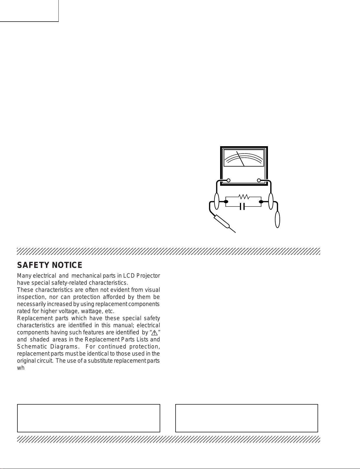
3. To be sure that no shock hazard exists, check for
current leakage in the following manner:
» Plug the AC cord directly into a 120-volt AC outlet,
(Do not use an isolation transformer for this test).
» Using two clip leads, connect a 1.5k ohm, 10 watt
resistor paralleled by a 0.15µF capacitor in parallel
between all exposed metal cabinet parts and earth
ground.
» Use an AC voltmeter with sensitivity of 5000 ohm per
volt., or higher, sensitivity to measure the AC voltage
drop across the resistor (See Diagram).
» All checks must be repeated with the AC plug
connection reversed. (If necessary , a non-polarized
adapter plug must be used only for the purpose of
completing these checks.)
Any reading of 0.3 volts RMS (this corresponds to
0.2 milliamp. AC.) or more is excessive and indicates
a potential shock hazard which must be corrected
before returning the unit to the owner.
AC
VOLTMETER
1.5k ohm (10W)
0.15µF
TEST PROBE
TO EXPOSED
METAL PARTS
CONNECT TO KNOWN
EARTH GROUND
234567890123456789012345678901212345678901234567890123456789012123456789012345678901234567890121
SAFETY NOTICE
Many electrical and mechanical parts in LCD Projector
have special safety-related characteristics.
These characteristics are often not evident from visual
inspection, nor can protection afforded by them be
necessarily increased by using replacement components
rated for higher voltage, wattage, etc.
Replacement parts which have these special safety
characteristics are identified in this manual; electrical
components having such features are identified by “å”
and shaded areas in the Replacement Parts Lists and
Schematic Diagrams. For continued protection,
replacement parts must be identical to those used in the
original circuit. The use of a substitute replacement parts
which do not have the same safety characteristics as
the factory recommended replacement parts shown in
this service manual, may create shock, fire or other
hazards.
AVIS POUR LA SECURITE
De nombreuses pièces, électriques et mécaniques, dans
les projecteur à LCD présentent des caractéristiques
spéciales relatives à la sécurité, qui ne sont souvent
pas évidentes à vue.
Le degré de protection ne peut pas être nécessairement
augmentée en utilisant des pièces de remplacement
étalonnées pour haute tension, puissance, etc.
Les pièces de remplacement qui présentent ces
caractéristiques sont identifiées dans ce manuel;
les pièces électriques qui présentent ces particularités
sont identifiées par la marque “å” et hachurées dans la
liste des pièces de remplacement et les diagrammes
schématiques. Pour assurer la protection, ces pièces
doivent être identiques à celles utilisées dans le circuit
d’origine. L’utilisation de pièces qui n’ont pas les mêmes
caractéristiques que les pièces recommandées par
l’usine, indiquées dans ce manuel, peut provoquer des
électrocutions, incendies ou autres accidents.
WARNING: The bimetallic component has the primary
234567890123456789012345678901212345678901234567890123456789012123456789012345678901234567890121
234567890123456789012345678901212345678901234567890123456789012123456789012345678901234567890121
conductive side exposed. Be very careful in
handling this component when the power is on.
AVERTISSEMENT: La composante bimétallique dispose du
conducteur primaire dénudé. Faire
attention lors de la manipulation de cette
composante sous tension.
4
Page 5
PG-C20XU
5
5
PG-C20XE
AN-Z7T
NOTE TO SERVICE
PERSONNEL
234567890123456789012345678901212345678901234
UV-RADIATION PRECAUTION
The light source, UHP lamp, in the LCD projector
emits small amounts of UV-Radiation.
A VOID DIRECT EYE AND SKIN EXPOSURE.
To ensure safety please adhere to the following:
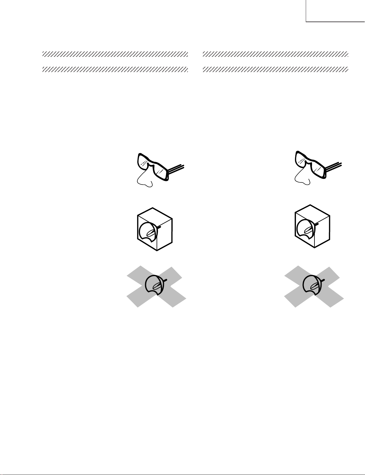
1. Be sure to wear sun-glasses when servicing the
projector with the lamp
turned “on” and the top
enclosure removed.
2. Do not operate the lamp outside of the lamp housing.
NOTE POUR LE PERSONNEL
D’ENTRETIEN
234567890123456789012345678901212345678901234
PRECAUTION POUR LES RADIATIONS UV
La source de lumière, la lampe UHP, dans le
projecteur LCD émet de petites quantités de
radiation UV.
EVITEZ TOUTE EXPOSITION DIRECTE
DES YEUX ET DE LA PEAU.
Pour votre sécurité, nous vous prions de respecter
les points suivants:
1. Toujours porter des lunettes de soleil lors d’un
entretien du projecteur
avec la lampe allumée
et le haut du coffret retiré.
2. Ne pas faire fonctionner la lampe à l’extérieur du
boîtier de lampe.
3. Do not operate for more than 2 hours with the
enclosure removed.
UV-Radiation and Medium Pressure
Lamp Precautions
1. Be sure to disconnect the AC plug when replacing
the lamp.
2. Allow one hour for the unit to cool down before
servicing.
3. Replace only with same type lamp. Type BQCPGC20X//1 rated 100V/200W.
4. The lamp emits small amounts of UV-Radiation, avoid
direct-eye contact.
5. The medium pressure lamp involves a risk of
explosion. Be sure to follow installation instructions
described below and handle the lamp with care.
3. Ne pas faire fonctionner plus de 2 heures avec le
coffret retiré.
Précautions pour les radiations UV
et la lampe moyenne pression
1. Toujours débrancher la fiche AC lors du
remplacement de la lampe.
2. Laisser l’unité refroidir pendant une heure avant de
procéder à l’entretien.
3. Ne remplacer qu’avec une lampe du même type.
Type BQC-PGC20X//1, caractéristique 100V/200W.
4. La lampe émet de petites quantités de radiation UVéviter tout contact direct avec les yeux.
5. La lampe moyenne pression implique un risque
d’explosion. Toujours suivre les instructions
d’installation décrites ci-dessous et manipuler la
lampe avec soin.
5
Page 6
PG-C20XU
4
5
PG-C20XE
AN-Z7T
UV-RADIATION PRECAUTION (Continued)
23456789012345678901234567890121234567890123
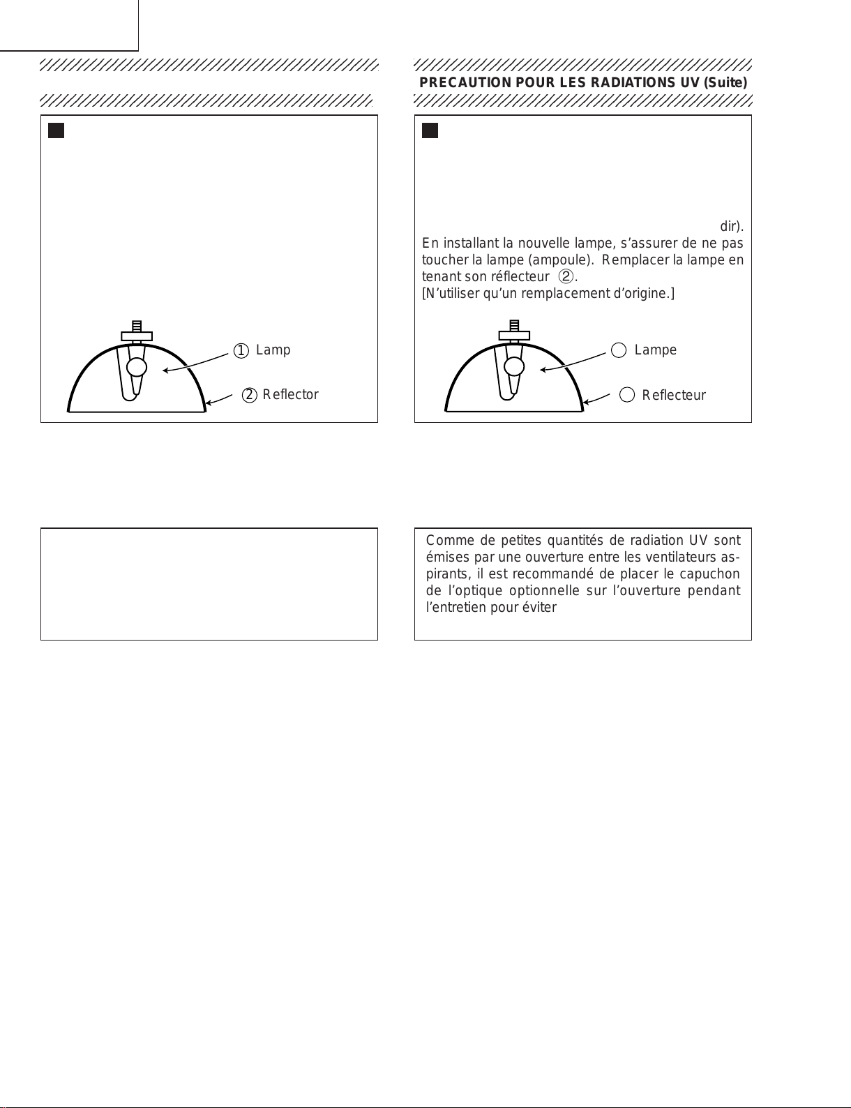
Lamp Replacement
Note:
Since the lamp reaches a very high temperature
during units operation replacement of the lamp
should be done at least one hour after the power
has been turned off. (to allow the lamp to cool off.)
Installing the new lamp, make sure not to touch the
lamp (bulb) replace the lamp by holding its reflector
2.
[Use original replacement only.]
Lamp
1
Reflector
2
DANGER ! –– Never turn the power on without the
lamp to avoid electric-shock or damage of the
devices since the stabilizer generates high voltages
at its start.
PRECAUTION POUR LES RADIATIONS UV (Suite)
234567890123456789012345678901212345678901234
Remplacement de la lampe
Remarque:
Comme la lampe devient très chaude pendant le
fonctionnement de l’unité, son remplacement ne doit
être effectué au moins une heure après avoir coupé
l’alimentation (pour permettre à la lampe de refroidir).
En installant la nouvelle lampe, s’assurer de ne pas
toucher la lampe (ampoule). Remplacer la lampe en
tenant son réflecteur 2.
[N’utiliser qu’un remplacement d’origine.]
1
Lampe
2
Reflecteur
DANGER ! –– Ne jamais mettre sous tension sans
la lampe pour éviter un choc électrique ou des
dommages des appareils car le stabilisateur génère
de hautes tensions à sa mise en route.
Since small amounts of UV-radiation are emitted from
an opening between the exhaust fans, it is recommended to place the cap of the optional lens on the
opening during servicing to avoid eye and skin exposure.
Comme de petites quantités de radiation UV sont
émises par une ouverture entre les ventilateurs aspirants, il est recommandé de placer le capuchon
de l’optique optionnelle sur l’ouverture pendant
l’entretien pour éviter une exposition des yeux et la
peau.
6
Page 7
PG-C20XU
2
PG-C20XE
AN-Z7T
WARNING: High brightness light source, do not stare into the beam of light, or view directly . Be especially
careful that children do not stare directly in to the beam of light.
WARNING: TO REDUCE THE RISK OF FIRE OR ELECTRIC SHOCK, DO NOT EXPOSE THIS UNIT TO
MOISTURE OR WET LOCATIONS.
CAUTION
RISK OF ELECTRIC SHOCK.
DO NOT REMOVE SCREWS
EXCEPT SPECIFIED USER
SERVICE SCREW
CAUTION: TO REDUCE THE RISK OF ELECTRIC SHOCK,
NO USER-SERVICEABLE P ARTS EXCEPT LAMP UNIT.
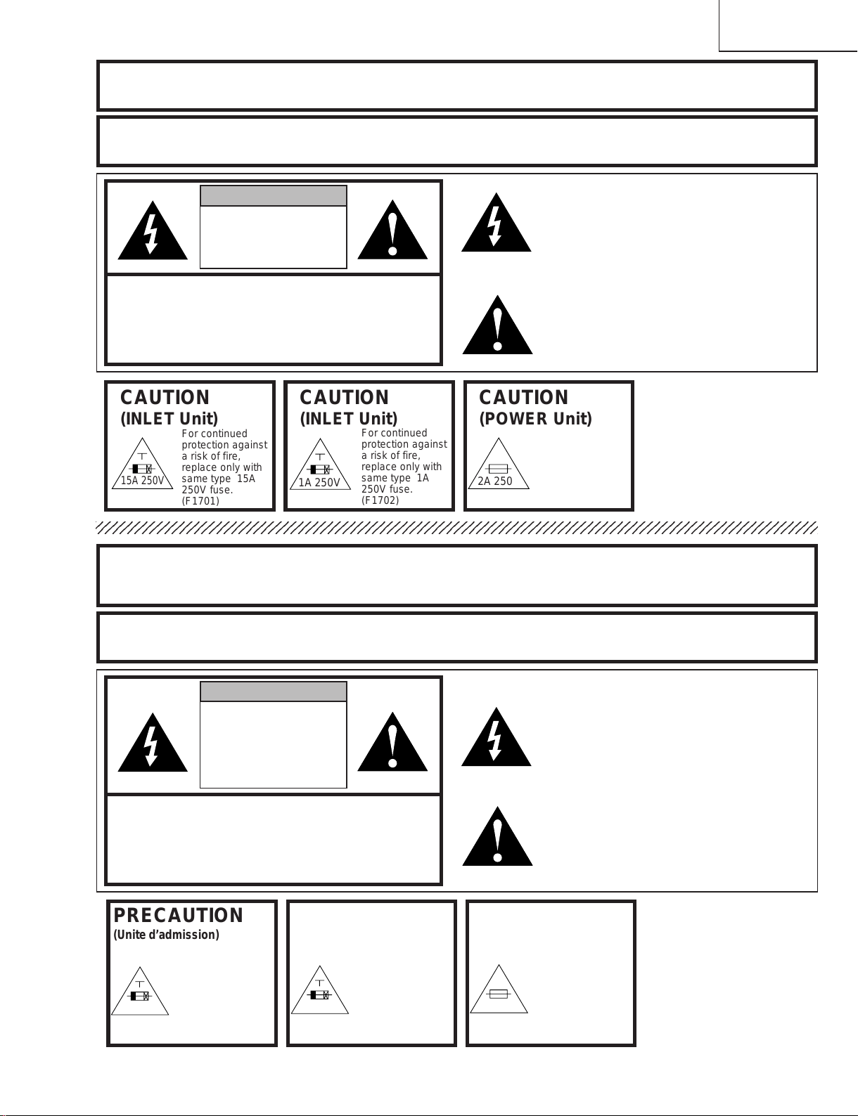
CAUTION
(INLET Unit)
15A 250V
234567890123456789012345678901212345678901234567890123456789012123456789012345678901234567890121
DO NOT REMOVE CABINET.
REFER SERVICING TO QUALIFIED SERVICE
PERSONNEL.
CAUTION
For continued
protection against
a risk of fire,
replace only with
same type 15A
250V fuse.
(F1701)
(INLET Unit)
1A 250V
For continued
protection against
a risk of fire,
replace only with
same type 1A
250V fuse.
(F1702)
CAUTION
(POWER Unit)
2A 250V
The lighting flash with arrowhead within a
triangle is intended to tell the user that
parts inside the product are risk of electric
shock to persons.
The exclamation point within a triangle is
intended to tell the user that important
operating and servicing instructions are in
the manual with the projector.
For continued
protection against a
risk of fire, replace
only with same type
P100A, ANZEN
DENGU, 2A, 250V
103°C fuse.(TF701)
A VERTISSEMENT : Source lumineuse de grande intensité. Ne pas fixer le faisceau lumineux ou le regarder
directement. Veiller particulièrement à éviter que les enfants ne fixent directement le
faisceau lumineux.
A VERTISSEMENT : AFIN D’EVITER TOUT RISQUE D’INCENDIE OU D’ELECTROCUTION, NE P AS PLACER
CET APPAREIL DANS UN ENDROIT HUMIDE OU MOUILLE.
ATTENTION
RISQUE
D’ELECTROCUTION NE
PASRETIRER LES VIS, A
L’EXCEPTION DES VIS DE
REPARATION UTILISATEUR
SPECIFIEES
L’éclair terminé d’une flèche à l’intérieur
d’un triangle indique à l’utilisateur que les
pi‘eces se trouvant dans l’appareil sont
susceptibles de provoquer une décharge
électrique.
Le point d’exclamation à l’intérieur d’un
ATTENTION: POUR EVITER TOUT RISQUE
D’ELECTROCUTION, NE PAS RETIRER LE CAPOT.
AUCUNE DES PIECES INTERIEURES N’EST REP ARABLE
PAR L’UTILISATEUR, A L’EXCEPTION DE L’UNITE DE
LAMPE. POUR TOUTE REP ARATION, S’ADRESSER A UN
PRECAUTION
(Unite d’admission)
15A 250V
TECHNICIEN D’ENTRETIEN QUALIFIE.
PRECAUTION
Pour une protection
continue contre les
risques d’incendie,
ne remplacer
qu’avec un fusible
15A 250V du même
type.
(F1701)
(Unite d’admission)
1A 250V
Pour une protection
continue contre les
risques d’incendie,
ne remplacer
qu’avec un fusible
1A 250V du même
type.
(F1702)
PRECAUTION
(Unité de PUTSSANCE)
2A 250V
triangle indique à l’utilisateur que les
instructions de fonctionnement et
d’entretien sont détaillées dans les
documents fournis avec le projecteur.
Pour une protection
continue contre un
risques d’incendie, ne
remplacer qu’avec un
fusible P100A, ANZEN
DENGU 2A 250V,
103°C du même type.
(TF701)
7
Page 8
PG-C20XU
PG-C20XE
AN-Z7T
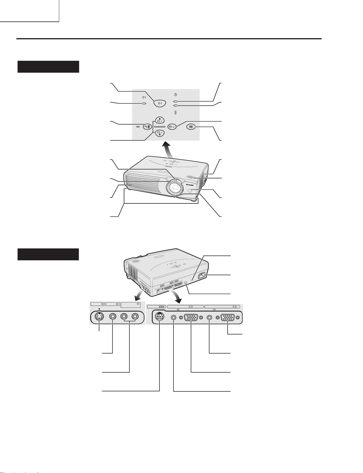
Location of Controls
Projector
Front and Top View
POWER indicator
INPUT/BACK button
KEYSTONE/Adjustment
Cooling fan (Exhaust vent)
Side and Rear View
ON/OFF button
(]/[ )buttons
ZOOM knob
FOCUS ring
Foot releases
POWER
INPUT
BACK
ON/OFF
KEYSTONE
LAMP
TEMP.
AUTO SYNC
ENTER
LAMP REPLACEMENT
indicator
TEMPERATURE WARNING
indicator
AUTO SYNC/ENTER button
MENU
MENU button
Air filter/Cooling fan
(Intake vent)
Speaker
Remote control sensor
Eyelet for
lens cap strap
Kensington Security
Standard connector
S-VIDEO INPUT 2 terminal
(4-pin Mini DIN)
VIDEO INPUT 3 terminal
(RCA)
AUDIO INPUT terminals
(RCA)
RS-232C port
(9-pin Mini DIN)
INPUT 2
S-VIDEO
INPUT 3 AUDIO INPUT
(S-VIDEO, VIDEO INPUT)
VIDEO
RS-232C
INPUT 1 OUTPUT (INPUT1)
AUDIO
COMPUTER
AUDIO
AC socket
Remote control sensor
COMPUTER
COMPUTER OUTPUT port
for INPUT 1
(HD 15)
AUDIO OUTPUT terminal
for INPUT 1
(3.5 mm stereo minijack)
COMPUTER INPUT 1 port
(HD 15)
AUDIO INPUT 1 terminal
(3.5 mm stereo minijack)
8
Page 9
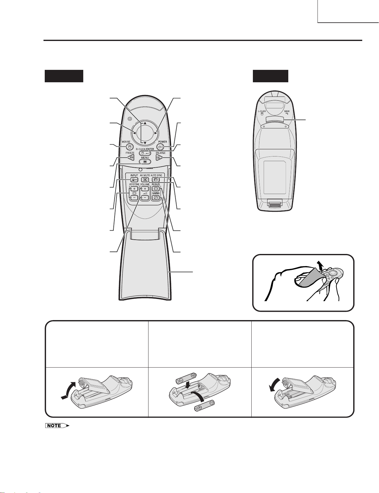
Remote Control
Front View
Rear View
Mouse (]/[)/
Adjustment (]/[)
buttons
Mouse (>)button
Mouse (<)button
MOUSE button
FREEZE button
MENU button
INPUT button
KEYSTONE buttons
VOLUME buttons
POWER button
RIGHT-CLICK/
ENTER button
ENLARGE button
AUTO SYNC button
AV MUTE button
RESIZE button
GAMMA button
Flip cover
LEFT-CLICK/
BACK button
Opening the Flip Cover
3
Press the tab and lift open
the battery cover in the
direction of the arrow.
Insert two AAA size
batteries,making sure
their polarities match the
+ and - marks inside
the battery compartment.
Inserting the Batteries
Insert the tabs on the
end of the battery cover
into their slots and press
the cover into position.
1
2
• If the remote control gets wet, wipe it dry immediately.
• Avoid excessive heat and humidity.
• If you will not be using the remote control for a long time, remove the batteries.
• Do not mix new and old or different types of batteries.
• There are operations that can only be carried out by remote control. Handle the remote control carefully.
PG-C20XU
PG-C20XE
AN-Z7T
9
Page 10
PG-C20XU
PG-C20XE
AN-Z7T
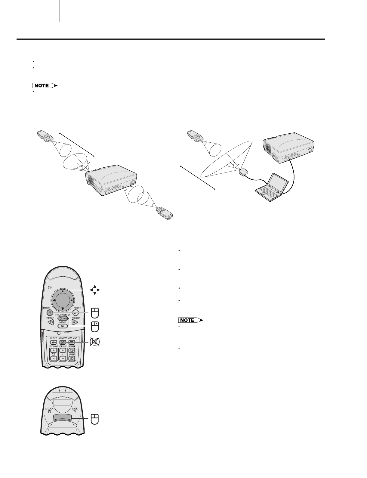
Remote Control/Mouse Receiver Positioning
The remote control can be used to control the projector within the ranges shown below.
The remote mouse receiver can be used with the remote control to control the mouse functions of a connected
computer within the ranges shown below.
The signal from the remote control can be reflected off a screen for easy operation. However, the effective distance of the
signal may differ due to the screen material.
Controlling the Projector
Remote control
23’ (7 m)
30ß
45ß
30ß
Effective buttons in MOUSE mode
Remote control
(Front view)
Mouse
MOUSE
45ß
30ß
Remote control
Using the Wireless Mouse
Remote control
30ß
30ß
120ß
13’(4 m)
Remote
mouse
receiver
Using as a Wireless Mouse
When MOUSE is pressed, the buttons on the remote
control light up and the remote control enters MOUSE
mode.
During MOUSE mode, the cursor can be used as the
pointer. MOUSE mode is for about ten seconds while
the buttons are lighting.
When MENU or ENLARGE is pressed, MOUSE mode
is released to the normal mode.
Be sure the supplied remote mouse receiver is
connected to your computer.
Remote control
(Rear view)
RIGHT-CLICK
AV MUTE
LEFT-CLICK
The wireless mouse may not operate correctly if your
computer serial port is not correctly set up. Refer to the
computer s operation manual for details of setting up/
installing the mouse driver.
For one-button mouse systems, use either the LEFT-CLICK
or RIGHT-CLICK button.
10
Page 11
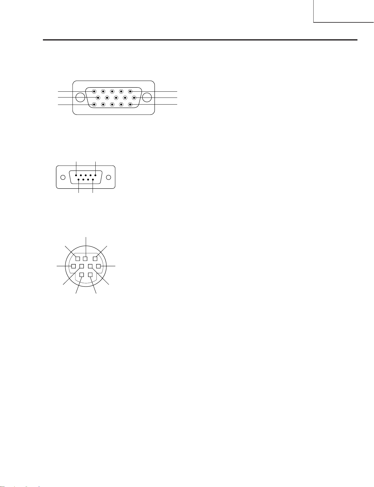
Connection Pin Assignments
COMPUTER INPUT 1 Port: 15-pin mini D-sub female connector
Computer Input
Analog
1. Video input (red)
2. Video input
(green/sync on green)
5
10
15
1
6
11
RS-232C Port: 9-pin D-sub male connector of the DIN-D-sub RS-232C cable
Pin No. Signal Name I/O Reference
1
5
69
1 Not connected
2 RD Receive Data Input Connected to internal circuit
3 SD Send Data Output Connected to internal circuit
4 Not connected
5 SG Signal Ground Connected to internal circuit
6 Not connected
7 Not connected
8 Not connected
9 Not connected
3. Video input (blue)
4. Not connected
5. Composite sync
6. GND (red)
7. GND (green/sync on green)
8. GND (blue)
PG-C20XU
PG-C20XE
AN-Z7T
9. Not connected
10.Not connected
11.GND
12.Bi-directional data
13.Horizontal sync signal
14.Vertical sync signal
15.Data clock
RS-232C Terminal: 9-pin Mini DIN female connector
8
9
6
5
2
7
4
1
Pin No. Signal Name I/O Reference
1 Not connected
2 RD Receive Data Input Connected to internal circuit
3 SD Send Data Output Connected to internal circuit
4 Not connected
3
5 SG Signal Ground Connected to internal circuit
6 Not connected
7 Not connected
8 Not connected
9 Not connected
11
Page 12
PG-C20XU
PG-C20XE
AN-Z7T
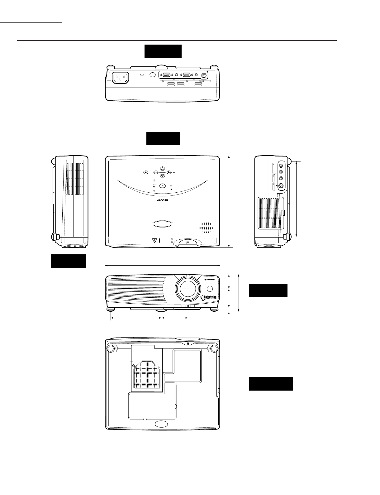
Dimensions
Rear View
Top View
Side View
21
4 / (118)
32
15
10 / (260)
64
9
32
2 / (58)
32
5
8 / (207)
64
17
1 / (32)
32
21
1 / (42)
16
5
/ (8)
Front View
64
15
3 / (82)
64
43
6 / (169.5)
12
Bottom View
Unit: inches (mm)
Page 13
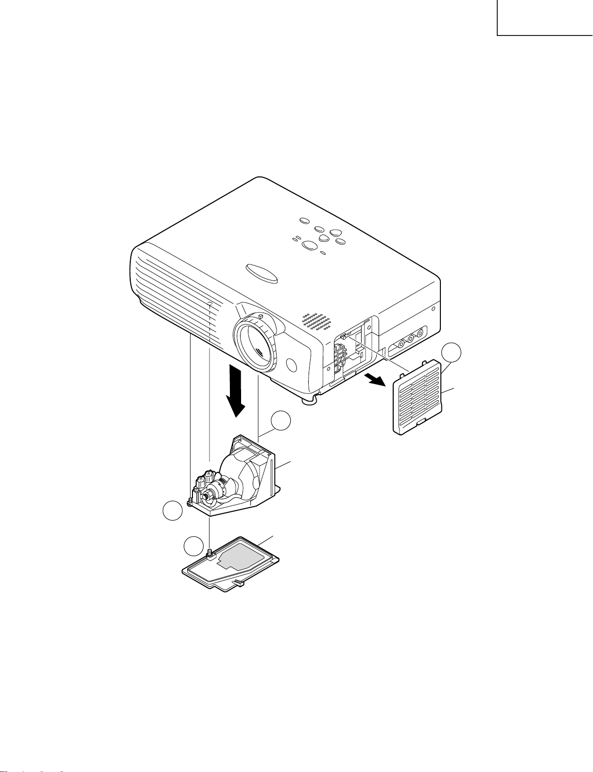
REMOVING OF MAJOR PARTS
1.Removing the intake cover and the lamp unit.
1-1. Detach the intake cover.
1-2. Remove the one lock screw (silver) from the lamp cover and detach the lamp cover.
1-3. Remove the two lock screws (silver) from the lamp unit and detach the lamp unit.
PG-C20XU
PG-C20XE
AN-Z7T
1-3
1-1
Intake cover
1-3
Lamp unit
Lamp cover
1-2
13
Page 14
PG-C20XU
PG-C20XE
AN-Z7T
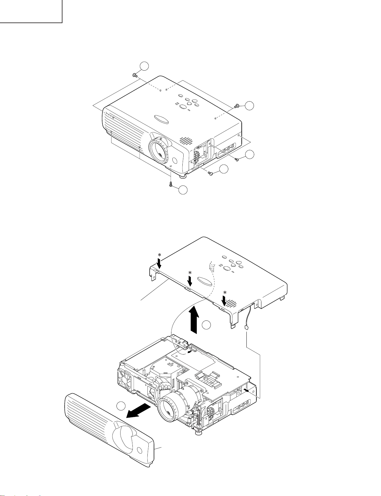
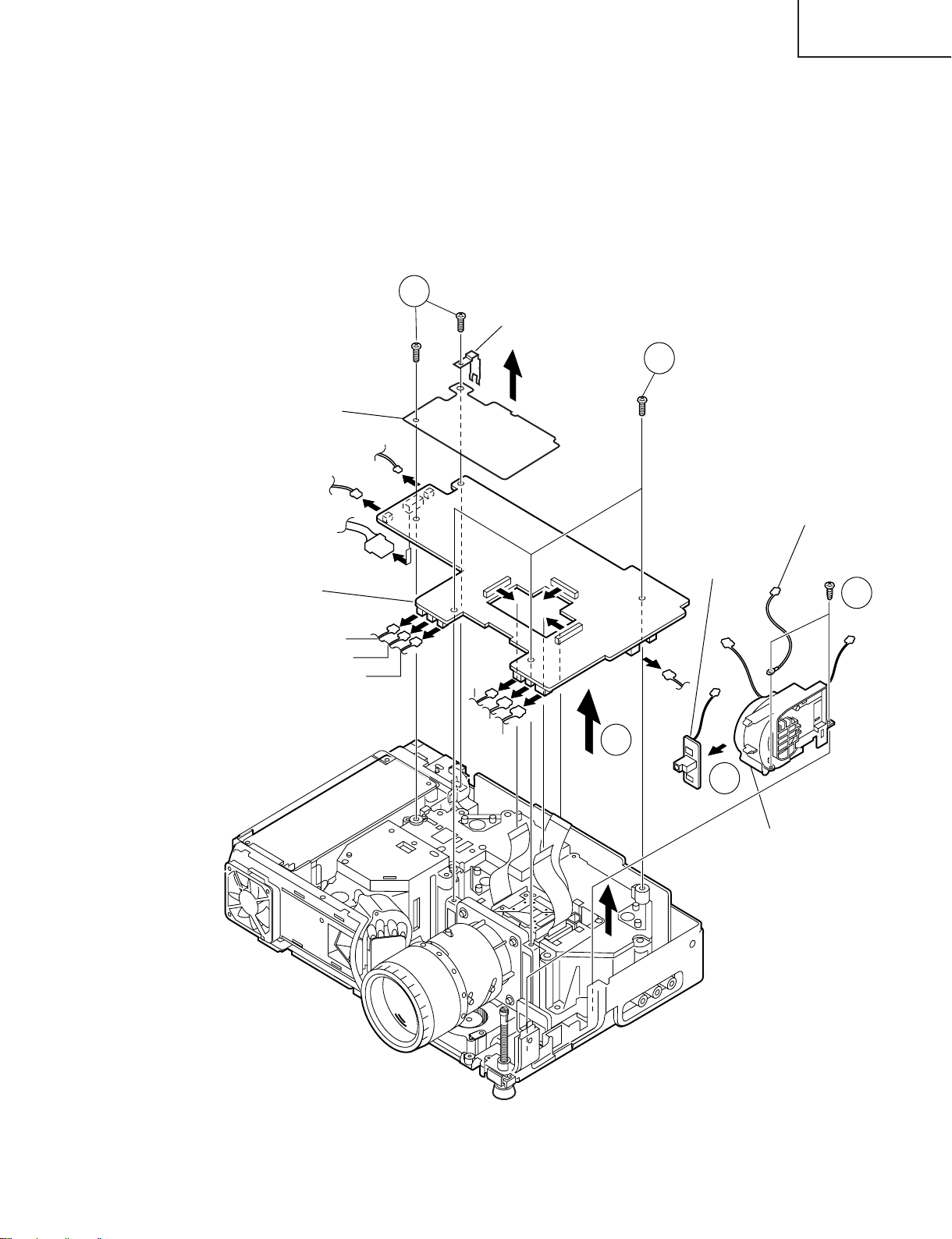
2.Removing the front and top panels
2-1. Remove the three lock screws (silver) from the front panel.
2-2. Remove the seven lock screws (silver) from the top panel.
2-2
2-2
2-2
2-2
2-1
2-3. Press the ❈-marked spots of the top panel to unhook the claws, and detach the top panel.
2-4. Slowly lift the top panel, disconnect the connectors from the control panel and speaker, and lift up the top
panel.
Top panel
2-4
2-3
Front Panel
14
Page 15
PG-C20XU
Intake fan unit
Remote control
receiver PWB
Temperature sensor
Output PWB
Grounding spring
3-2
3-4
3-3
3-1
3-1
Electrostatic sheet
(PG-C20XU Only)
(P1702)
(P1707)
(P1703)
(P1705)
(SC1102)
(SC1202)
(SC1302)
(P1601)
(P1708)
(P1706)
(P1704)
(P1602)
(P1701)
PG-C20XE
AN-Z7T
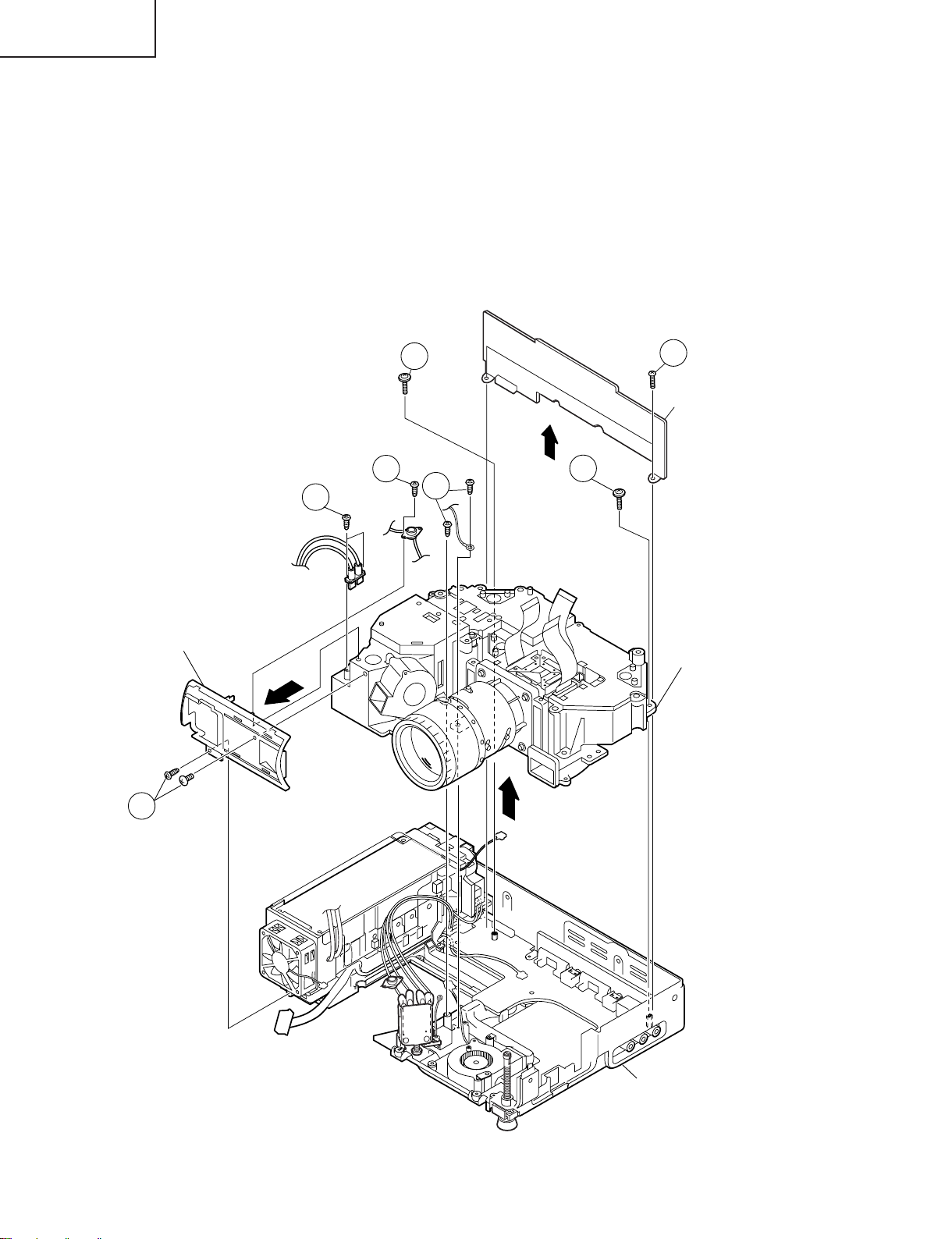
3.Removing the output PWB unit, remote control receiver PWB unit and intake
fan unit
3-1. Remove the five lock screws (yellow) from the output PWB unit. Remove the grounding spring and the
electrostatic sheet (PG-C20XU only).
3-2. Lift the output PWB unit, disconnect the connectors and lift up the output PWB unit.
3-3. Remove the two lock screws (black) from the intake fan unit and detach both the intake fan unit and the
temperature sensor.
3-4. Unhook the claws of the intake fan unit off the remote control receiver PWB unit, and detach this unit.
15
Page 16
PG-C20XU
PG-C20XE
AN-Z7T
4.Removing the front duct unit, PC I/F PWB units, and optical mechanism unit
4-1. Remove the lock screw (silver) from the bimetal and detach the bimetal.
4-2. Remove the two lock screws (one in black, the other in silver) from the front duct unit and detach the front
duct unit.
4-3. Remove the two lock screws (yellow) from the PC I/F PWB unit. Detach this unit from above.
4-4. Remove the two lock screws (silver) from the lamp socket holder and detach the lamp socket holder.
4-5. Remove the four lock screws (two in black, two in yellow) from the optical mechanism unit and detach the
optical mechanism unit from above.
Front duct unit
4-4
4-1
4-5
4-3
PC I/F PWB
unit
4-5
4-5
Optical
mechanism
unit
4-2
Bottom panel
16
Page 17
PG-C20XU
PG-C20XE
AN-Z7T
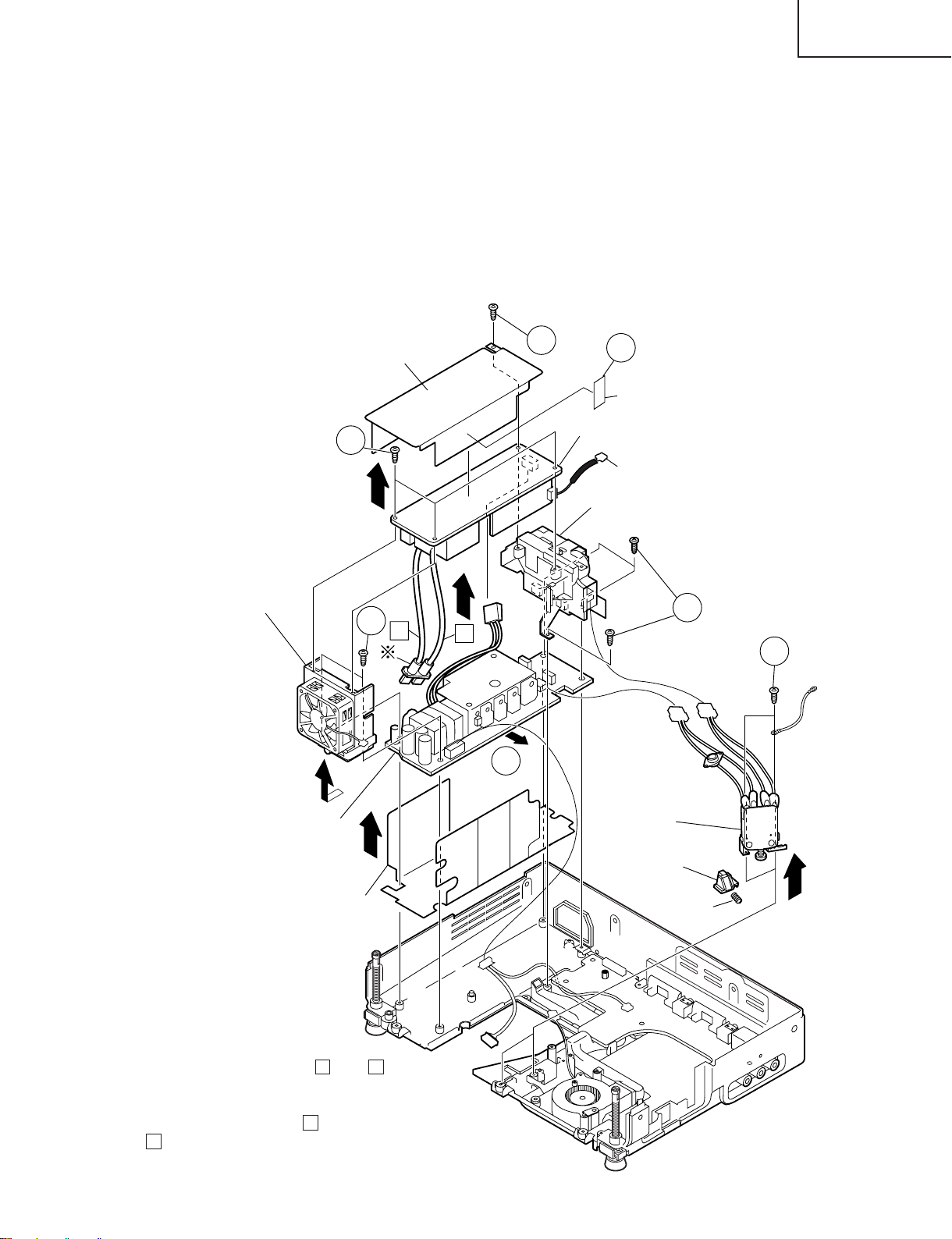
5.Removing the ballast/power/AC inlet PWB unit, cooling fan and AC select
switch
5-1. Remove the lock screw (yellow or silver) from the ballast cover. Peel the Teflon tape that secures the lead
wires on the ballast cover. Detach the ballast cover.
5-2. Remove the three lock screws (yellow or silver) from the ballast PWB unit. Disconnect the connectors from
the power PWB unit and detach the ballast PWB unit.
5-3. Remove the two lock screws (silver) from the cooling fan/power PWB unit and detach the cooling fan unit.
5-4. Remove the three lock screws (silver) from the AC inlet/power PWB unit. Disconnect the AC select switch
connectors and the power PWB connector (EA). Detach the AC inlet PWB unit, power PWB unit and power
PWB unit cover.
5-5. Remove the two lock screws (yellow) from the AC select switch and detach the switch, slide and spring.
Cooling fan
Ballast cover
5-2
5-3
5-1
5-1
Teflon tape
Ballast PWB
Note: Be careful when connecting this
connector close to the live part of the
()
ballast PWB unit.
AC inlet PWB unit
5-4
B
A
5-5
5-4
Power PWB unit
Power PWB unit cover
❋ Precautions in reassembling
Keep the high-voltage leads ( A and B in
the figure) of the lamp socket on the
ballast PWB out of contact with the cooling
fan. To do this, lay the lead B behind the
lead A and dress them up in the cooling
fan holder notch.
AC select switch
Slide
Spring
(EA)
17
Page 18
PG-C20XU
PG-C20XE
AN-Z7T
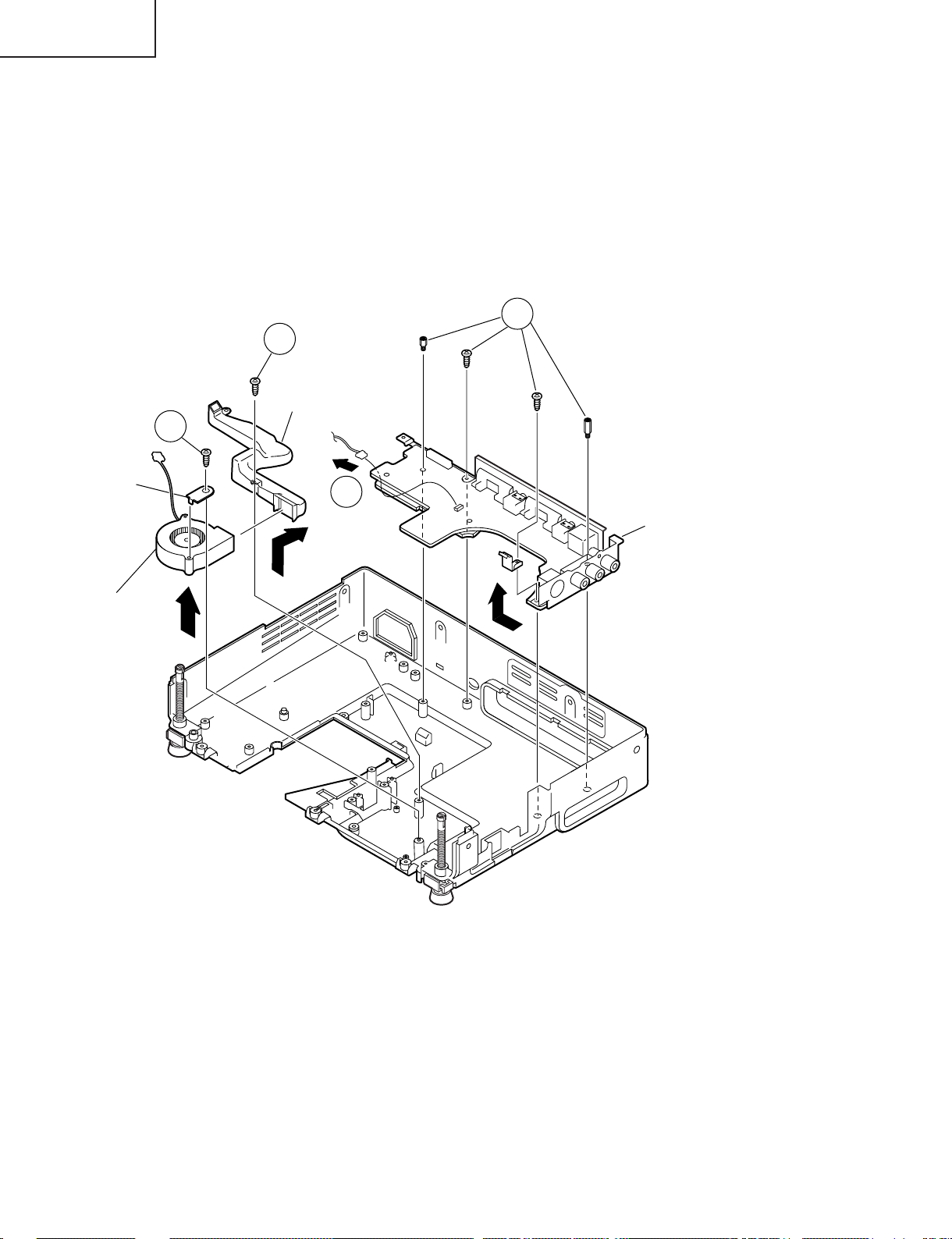
6.Removing the connecting terminals/3-dimensional Y/C separation PWB unit
assembly
6-1. Remove the two lock screws (yellow) and the two supports from the connecting terminals/3-dimensional Y/
C separation PWB unit assembly. Slide the PWB unit and draw the terminals out of the bottom plate.
6-2. Disconnect the connector (EA) from the connecting terminals PWB unit.
7.Removing the center duct and the PBS fan
7-1. Remove the one lock screw (yellow) from the center duct and detach the center duct.
7-2. Remove the one lock screw (yellow) from the PBS fan and detach the angle and the PBS fan.
6-1
7-1
Center duct
Angle
PBS fan
7-2
(EA)
6-2
Connecting terminals/
3-dimensional
Y/C separation PWB
unit assembly
18
Page 19
Resetting the TOTAL LAMP TIMER
CAUTION
Intense light hazard. Do not attempt to look into the aper ture and lens while the projector is operating.
As the usage environment can vary significantly, the projector lamp may not operate for 1,000 hours.
"1,000 hours" above indicates average life span and should be used for r eference only. This is different than the warranty period.
For safety, the power will not be turned on from the fourth times when turning on the power without changing the lamp after use for 1,000
hours.
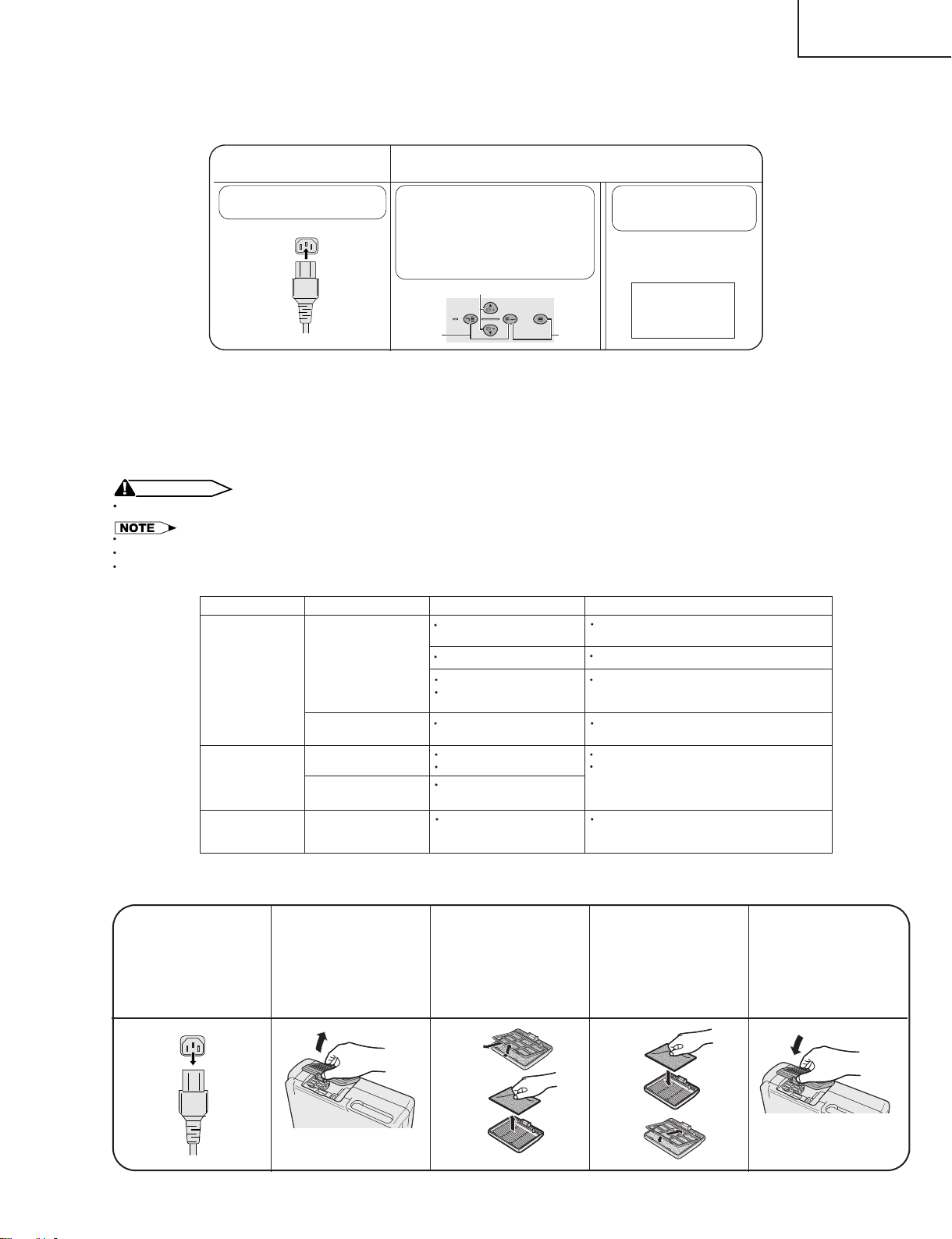
● Resetting the total lamp timer
When replacing the lamp, reset the total lamp timer in the procedure below.
PG-C20XU
PG-C20XE
AN-Z7T
Connect the power cord.
1
Plug the power cord into the AC
socket of the projector.
Reset the lamp timer.
2
1 Press KEYSTONE ' and
KEYSTONE " on the projector at
the same time.
2 Press INPUT and AUTO SYNC on
the projector at the same time.
3Press AUTO SYNC and MENU at
the same time until unit comes on.
1
INPUT
AUTO SYNC
BACK ENTER MENU
2
3
LAMP 0000H
displayed, indicating that
the lamp timer is reset.
LAMP 0000H
is
● Light source (lamp)
The lamp used for light source has a service life of about 1,000 hours. If the total operating time exceeds 900
hours, replace the lamp with new one (separately sold) as soon as possible. However, if the image becomes
dim or the colors get less crisp even before the total operating time does not exceeds 900 hours, also replace
the lamp. The lamp's total operating time can be checked on the screen. If noticeable color irregularities are
found after replacing the lamp, make the color irregularity correction on page 28.
Maintenance Indicator
TEMPERATURE
WARNING
indicator
LAMP
REPLACEMENT
indicator
POWER indicator
Condition Possible Solution
The internal
temperature is
abnormally high.
The indicator flashes in
red.
The lamp does not
illuminate.
The lamp requires
replacement.
The indicator flashes in
red when the projector
is on.
Problem
Blocked air intake.
Clogged air filter.
Cooling fan breakdown.
Internal circuit failure.
Cooling down. Wait until the indicator stops flashing and
Burnt-out lamp.
Lamp circuit failure.
Lamp has been used for
over 900 hours.
The filter cover is open. Securely install the filter cover
Relocate the projector to an area with proper
ventilation.
Clean the filter.
Take the projector to your nearest Authorized
Sharp Industrial LCD Products Dealer or
Service Center for repair.
turns off.
Carefully replace the lamp.
Take the projector to your nearest Authorized
Sharp Industrial LCD Products Dealer or
Service Center for repair.
.
● Replacing the air filter
Just when replacing the lamp, replace also the air filter with the one that comes with the lamp replacement kit.
1.Disconnect the power
cord.
Unplug the power cord
from the AC socket.
r
2.Remove the filter cover.
Turn over the projector.
Press the tab and remove
the filter cover in the direction of the arrow.
3.Remove the air filter.
1 Remove the air filter
stopper.
2 Remove the air filter.
1
2
19
4.Replace the air filter.
1 Put the new air filter
into position.
2 Put the air filter stopper
back into position.
1
2
5.Replace the filter cover.
Insert the tab on the end of
the filter cover into the filter
cover opening and press
the filter cover into
position.
Page 20
PG-C20XU
PG-C20XE
AN-Z7T
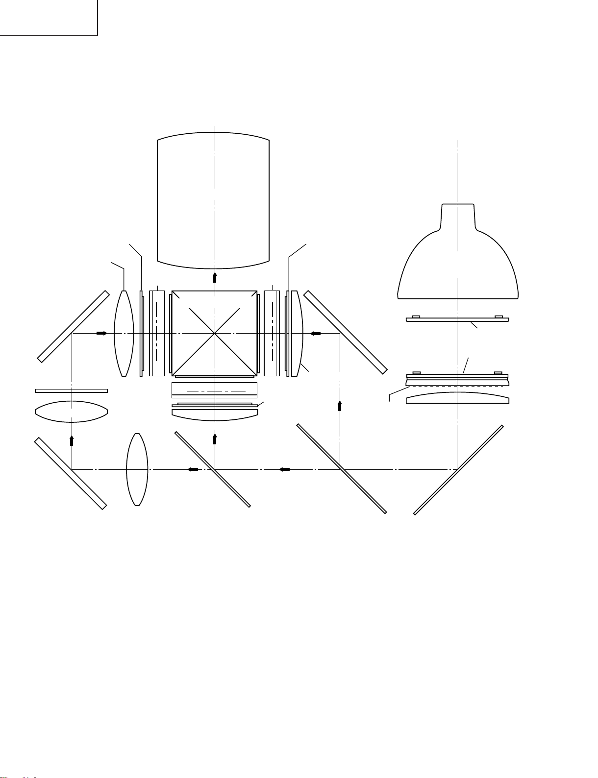
THE OPTICAL UNIT OUTLINE
Layout for proper setup of the optical components and parts (top view)
Projection Lens
Input polarizer B
Relay lens 3
M6
Mirror R, G, B
F1
Relay lens 2
Mirror R, G, B
G03
UV absorbing glass
G02
M4
Relay lens 1
LCD(B)
LCD(G)
L3
G01
Cross dichroic prism
Condencer lens G
Green
Blue
G reflector
M3
LCD(R)
Condencer lens R
Input polarizer G
Green/Blue
Input polarizer R
AL-coated mirror R
L2
Red
M2
M5
PBS
R reflector
Light source
(Lamp)
Fly-eye lens (Input)
Fly-eye lens (Output)
L1
AL-coated mirror R,G, B
M1
20
Page 21
PG-C20XU
Lamp assembly (bottom view)
Screw B
Screw A
Screw C
D
PG-C20XE
AN-Z7T
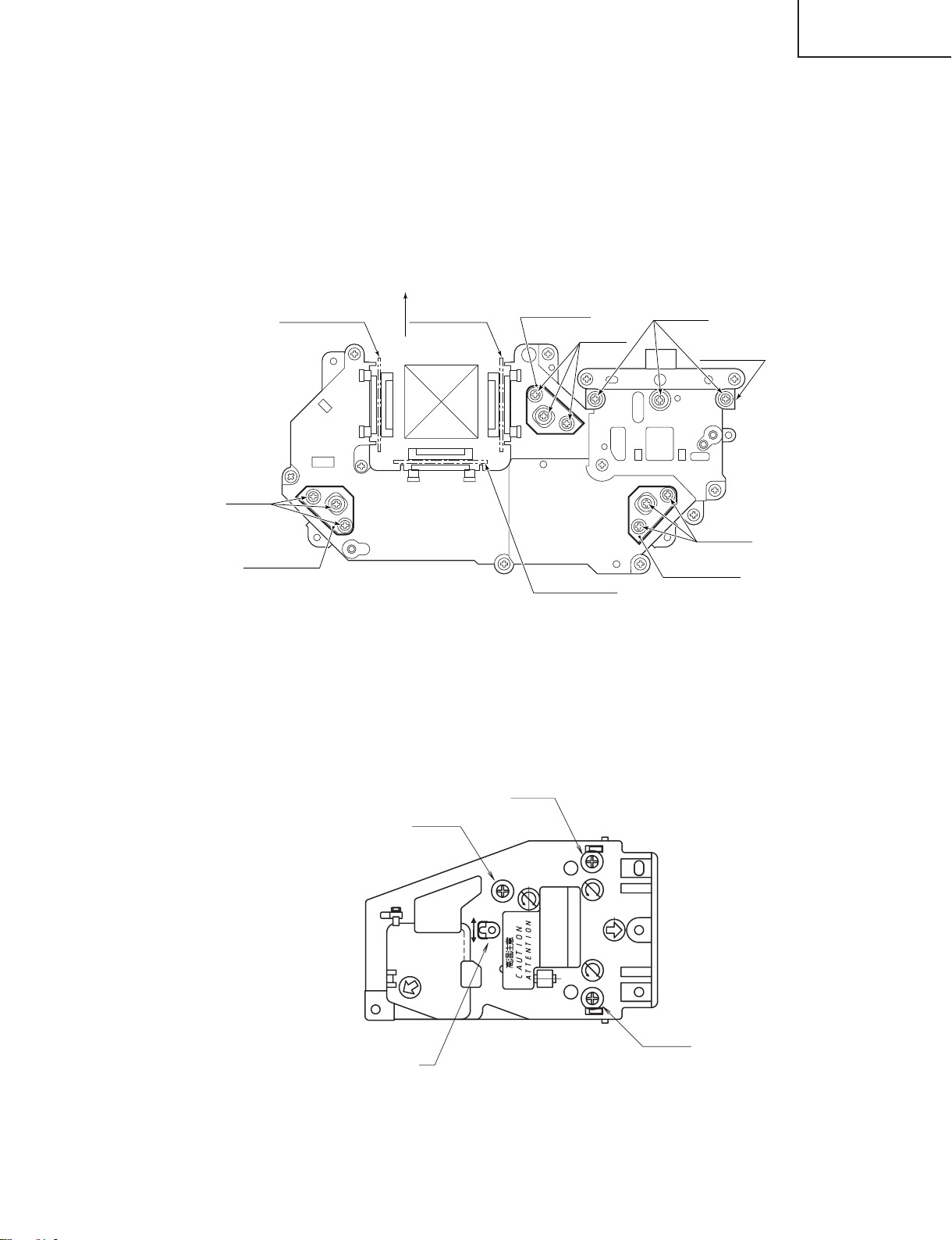
Adjusting the mirrors
This adjustment is needed when any of the optical parts of the optical mechanism has been replaced.
1. Disconnect the flat cables from all the LCD panels.
2. Light up the lamp.
3. Project a white-light image and check to see if there is any color tint in any direction. If any, loosen the incident-light
fly-eye adjusting plate lock screws and readjust the fly-eye to get the image uniformly whitish. Tighten up the lock
screws.
4. If by any chance the above step 3 fails, use the M1, M4 and M5 adjusting levers.
5. Before moving the M5 adjusting lever, shield the G and B color beams. (For shielding them, use reflective sheets
that reflect the incident lights.)
6. Loosen the adjusting lever lock screws, make adjustments, and tighten up the lock screws.
7. Before moving the M4 adjusting lever, shield the R and G color beams.
Lock screws
(yellow)
M4 Adjusting lever
Shielding plate for B
Front
Shielding plate for R
M5 Adjusting lever
Shielding plate for G
Lock screws
(yellow)
Lock screws
(yellow)
incident-light fly-eye
adjusting plate
Lock screws
(yellow)
M1 Adjusting lever
Correcting color irregularities on white-only screen when replacing the lamp
If color irregularities are found at the right and left on a white-only screen after replacing the lamp, it is necessary to
readjust the optical axis of the new lamp. Take the following steps.
1. Open the lamp cover and loosen the screws A, B and C at the bottom of the lamp.
2. Using a screwdriver or the like, move the U-shaped groove at the window D in the arrow direction.
3. Temporarily fix the screws A, B and C, close the lamp cover, and check the white-only screen again for color
irregularities.
4. Repeat the above steps 1, 2 and 3 until there will be no color irregularities. Now tighten up the screws A, B and C.
5. Finally secure the lamp cover back in position.
21
Page 22
PG-C20XU
PG-C20XE
AN-Z7T
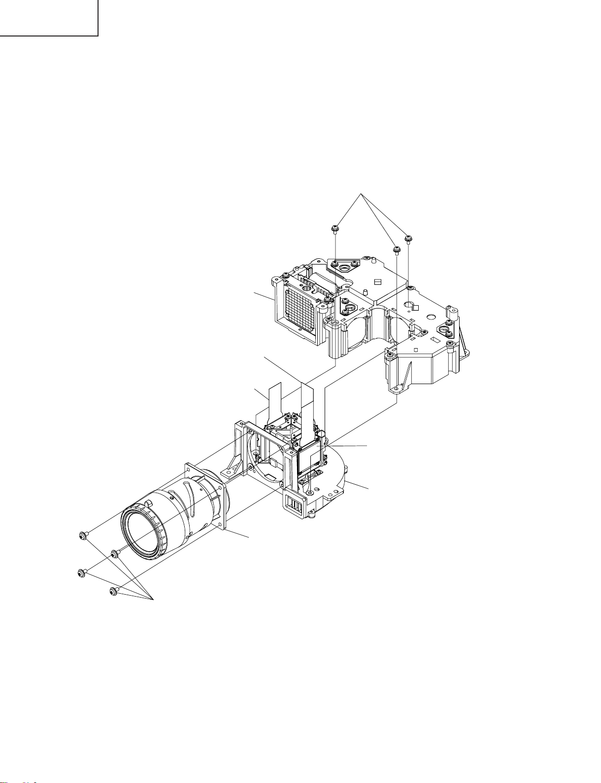
Replacing the prism holder unit
1. Remove the three lock screws, and take the prism holder unit and the projection lens assembly out of the optical
unit.
2. Remove the four lock screws, separate the prism holder unit and the projection lens assembly from each other.
3. Replace the prism holder unit with new one. Take the above steps 1 and 2 in reverse order.
Note: Even if just one of the LCD panels is defective, it is necessary to replace the entire prism holder unit. Do not
replace just the defective LCD panel only.
1Prism holder unit lock screws
(yellow)
Optical unit
G-LCD panel
R-LCD panel
Projection lens assembly
2Projection lens lock screws (yellow)
B-LCD panel
Prism holder unit
22
Page 23
PG-C20XU
PG-C20XE
ELECTRICAL ADJUSTMENT
Hook up a signal generator, or a DOSV or Mac personal computer to the projector in order to feed the
signals specified in the Adjusting conditions.
ADJUSTMENT PRECAUTIONS
1 Precautions for initializing
It takes 5 seconds to get the memory initialized and the initial settings rewritten. To go through the initialization, the
onscreen display background on the process menu screen turns red and the message "INITIALIZE" appears
onscreen for 5 seconds after pressing the specified key. Finally turn off the AC power (unplug the power cord).
2 Initial factory settings (S4, S5)
It takes 5 seconds to get the initial factory settings written. Do not turn off the main power during this procedure. To
ensure this waiting time, "S4" or "S5" appears on the onscreen display for 5 seconds. When this sign disappears,
you can keep on the power or turn it off.
3 Video adjustment
Be careful not to cut off the signals during the video adjustment.
No. Adjusting point Adjusting conditions Adjusting procedure
AN-Z7T
1 EEPROM
initialization
2 Brightness
adjustment
1. Turn on the power (with the
lamp on) and warm up the
set for 15 minutes.
2. Select the following group,
sub-group and subject.
Group : Option
Sub-group:
EEPROM Initialize
Subject : Initialize Start
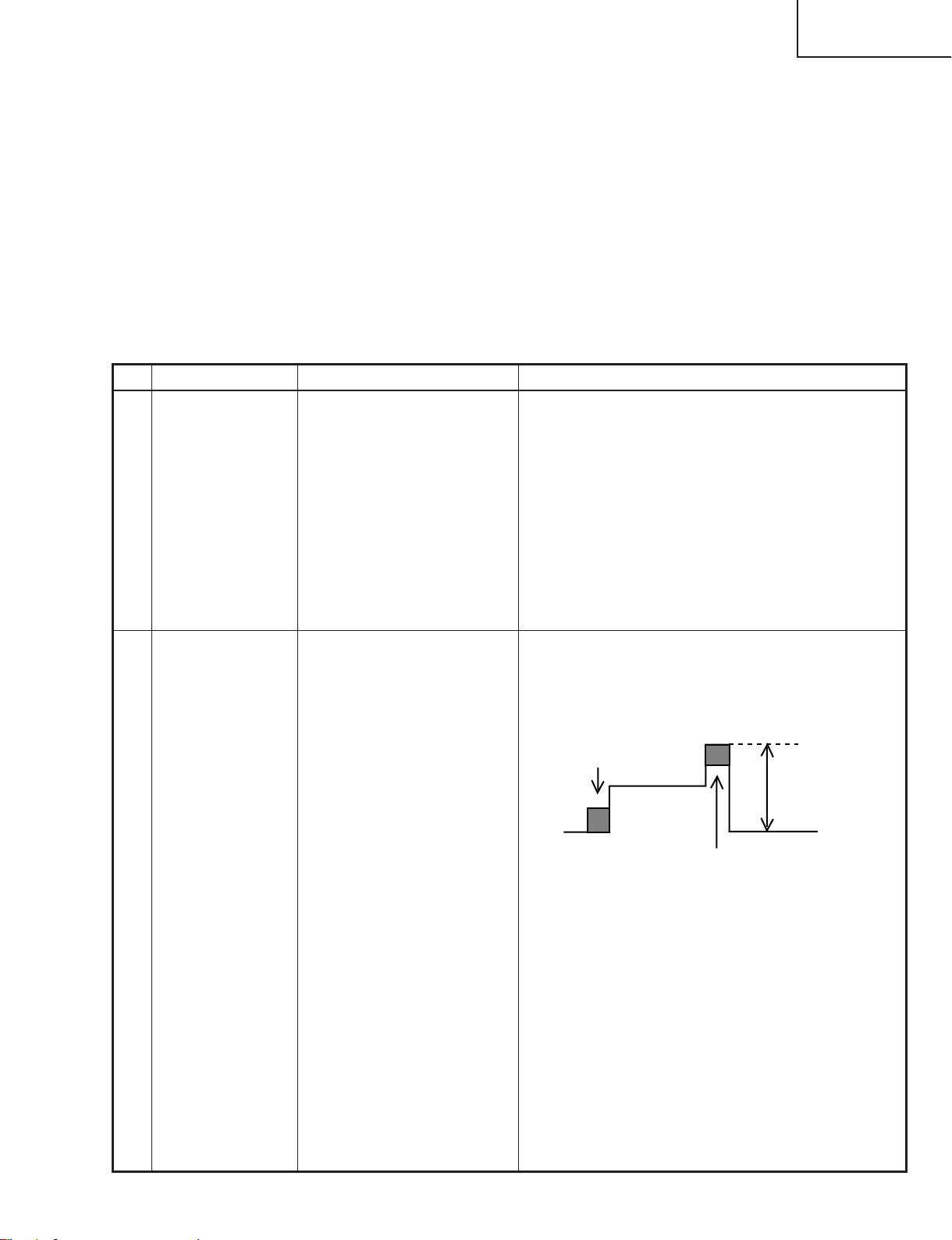
1. Feed the XGA 10-step signal.
2. Select the following group,
sub-group and subjects.
Group : Adjust PC Image
Sub-group: AD
Subject :
R-Bright (In R adjustment)
G-Bright (In G adjustment)
B-Bright (In B adjustment)
3. Connect the synchroscope
(0.2V/div.) to the following
TPs.
In R adjustment TP1403
In G adjustment TP1402
In B adjustment TP1401
» Make the following settings.
Press SW1601 to call the process mode. Initialize
the EEPROM by execution of Initialize Start. (After
the execution of Initialize Start, the EEPROM will not
be initialized unless the power is once turned off.)
» Adjust the setting just until the color tone level 0 starts
moving.
0-gradation
0.8Vp-p
10-gradation
23
Page 24
PG-C20XU
PG-C20XE
AN-Z7T
No. Adjusting point Adjusting conditions Adjusting procedure
3 Drive adjust-
ment
4 Panel input
signal amplitude
adjustment
1. Feed the XGA 10-step signal.
2. Select the following group,
sub-group and subjects.
Group : Adjust PC Image
Sub-group: AD
Subject :
R-Contrast (In R adjustment)
G-Contrast (In G adjustment)
B-Contrast (In B adjustment)
3. Connect the synchroscope
(0.2V/div.) to the following
TPs.
In R adjustment TP1403
In G adjustment TP1402
In B adjustment TP1401
1. Select the following group,
sub-group and subjects.
Group : Adjust PC image
Sub-group: CXA2111R
Subject :
AMP-R-GAIN (In R adjustment)
AMP-R-BLK (In R adjustment)
AMP-G-GAIN (In G adjustment)
AMP-G-BLK (In G adjustment)
AMP-B-GAIN (IN B adjustment)
AMP-B-BLK (IN B adjustment)
2. Connect the synchroscope
to the following TPs.
In R adjustment TP1101
In G adjustment TP1201
In B adjustment TP1301
3. Feed the XGA 10-step signal.
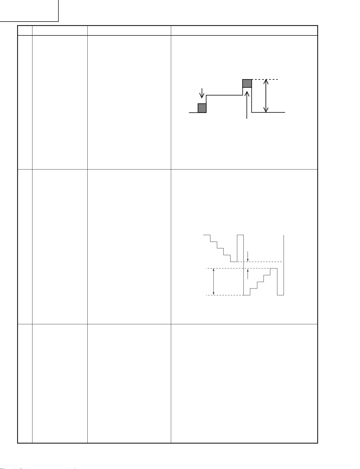
» First reach a setting where the color tone level 10
gets saturated. Then decrease the setting by one
point.
0-gradation
0.8Vp-p
10-gradation
1.Select AMP-R-GAIN and adjust the signal amplitude
to 3.8 ± 0.1. Select 0.1Vp-p.
2.Select AMP-R-BLK and adjust the white-white signal amplitude to 2.1 ± 0.1Vp-p.
Note: Make sure that the black side does not interfere
in GAIN adjustment.
Adjust the amplitude as for G and B in the same
procedure.
2.1Vp-p
3.8Vp-p
5 Sample hold
pulse phase
checking
1. Feed the XGA mode monochrome signal.
2. Select the following group,
sub-group and subjects.
Group : LCD2(6050)
Sub-group: CLDLY
Subject : R_CLDLY
G_CLDLY
B_CLDLY
R_REVCLDLY
G_REVCLDLY
B_REVCLDLY
» Feed the G (30%) signal to see if there is no vertical
stripe visible on the screen. If it is visible, adjust the
setting to somewhere between 160 and 200.
Make also sure that the R and B settings are as follows.
R_CLDLY 171
R_REVCLDLY 175
B_CLDLY 175
B_REVCLDLY 178
24
Page 25
No. Adjusting point Adjusting conditions Adjusting procedure
PG-C20XU
PG-C20XE
AN-Z7T
6 RGB
countervoltage
adjustment
7 RGB tone
reproduction
adjustment
1. Feed the countervoltage
adjustment signal. (XGA)
2. Select the following group,
sub-group and subjects.
Group : LCD2 (6050)
Sub-group: COM
Subject :
R_LCCOM (In R adjustment)
G_LCCOM (In G adjustment)
B_LCCOM (In B adjustment)
R_REVLCCOM (In R reverse adjustment)
G_REVLCCOM (In G reverse adjustment)
B_REVLCCOM (In B reverse adjustment)
1. Feed the green-only
SMPTE pattern signal.
(XGA)
2. Select the following
group, sub-group and
subject.
Group : Adjust PC Image
Sub-group: CXA211 1R
Subject : AMP-BLK
» Using the set's control switch or the remote control-
ler’s button, adjust the setting so that the flickering
be minimum.
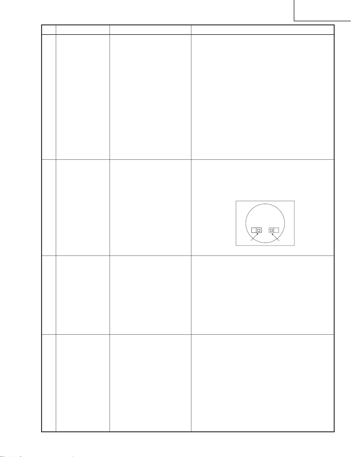
» Adjust the setting so that the image comes to the
center of the screen.
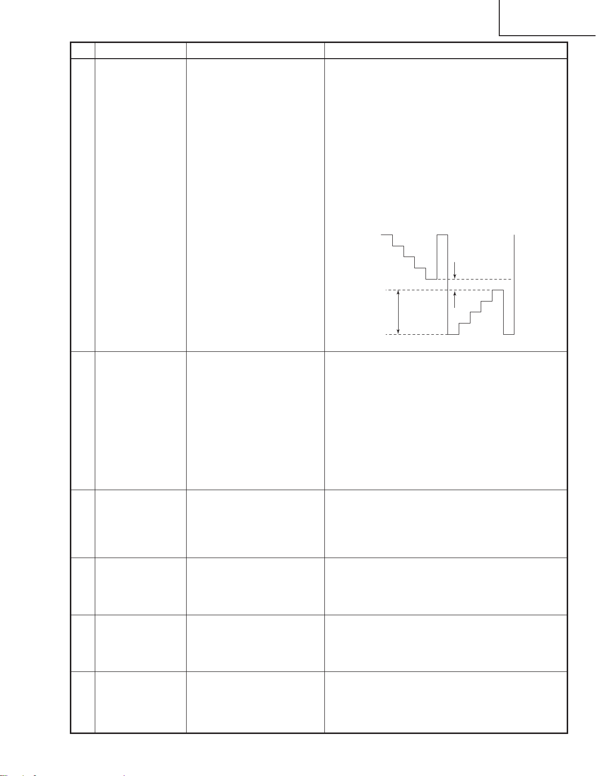
» Adjust the AMP-BLK setting so that the gradation of
the part 1 (white 95% and 100%) as shown in the
figure below is barely discernible.
» Make sure that the gradation of the part 2 (black
0% and 5%) is also discernible.
8 RGB white
balance adjustment
9 Horizontal
center adjustment
1. Feed the 32-step grayscale signal. (XGA)
2. Select the following group,
sub-group and subjects.
Group : Adjust PC Image
Sub-group: CXA211 1R
Subject : AMP-R-BLK
(In R adjustment)
AMP-B-BLK
(In B adjustment)
1. Feed the NTSC
monoscope signal.
2. Select the following
group, sub-group and
subject.
Group :
Adjust VIDEO Image
Sub-group: VPC3230
Subject : H-Position
2
1
» Adjust the setting to achieve the best color tone
balance.
» Make sure the setting is 52.
25
Page 26
PG-C20XU
PG-C20XE
AN-Z7T
No. Adjusting point Adjusting conditions Adjusting procedure
10 Video BRIGHT-
NESS adjustment
11 Video CON-
TRAST adjustment
12 Color saturation
adjustment
1. Feed the NTSC 10-step
signal.
2. Select the following group,
sub-group and subject.
Group :
Adjust VIDEO Image
Sub-group: VPC3230
Subject : Bright
1. Feed the NTSC 10-step
signal.
2. Select the following group,
sub-group and subject.
Group :
Adjust VIDEO Image
Sub-group: VPC3230
Subject : Contrast
3. Connect the synchroscope
to TP1402.
1. Feed the color bar signal.
2. Select the following group,
sub-group and subject.
Group :
Adjust VIDEO Image
Sub-group: VPC3230
Subject : Color
» Make sure the setting is as shown below.
PG-C20XU ........142
PG-C20XE ........145
» First reach a setting where the color tone level 10
gets saturated. Then decrease the setting by one
point.
0-gradation
0.8Vp-p
10-gradation
» Make sure the setting is 128.
13 PSIG adjust-
ment
1. Select the following group,
sub-group and subjects.
Group :
Adjust VIDEO image
Sub-group: CXA2111R
Subject : PRGLEV
SIDLEV
2. Connect the synchroscope
to TP1210.
3. Using the NTSC 10-step
input signal, make sure that
there is no vertical stripes
appearing every 12 dots. (If
white or black vertical
stripes appear, fine-adjust
the SIDLEV setting.)
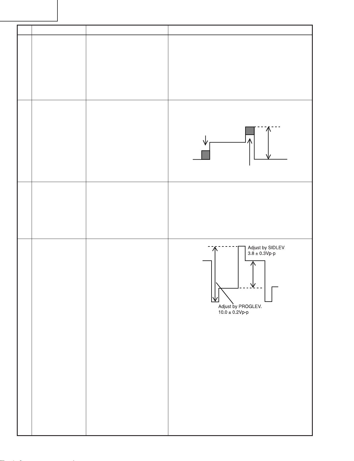
PSIG
» Make sure the setting is as shown below.
PRGLEV ...........61
SIDLEV .............170
26
Page 27
No. Adjusting point Adjusting conditions Adjusting procedure
14 VIDEO panel
input signal
amplitude
adjustment
1. Select the following group,
sub-group and subjects.
Group :
Adjust VIDEO image
Sub-group: CXA2111R
Subject :
AMP-R-Gain (In R adjustment)
AMP-R-BLK (In R adjustment)
AMP-G-Gain (In G adjustment)
AMP-G-BLK (In G adjustment)
AMP-B-Gain (IN B adjustment)
AMP-B-BLK (IN B adjustment)
2. Connect the synchroscope
to the following TPs.
In R adjustment TP1101
1.Select AMP-R-Gain and adjust the signal amplitude
to 3.8 ± 0.1Vp-p.
2.Select AMP-R-BLK and adjust the white-white signal amplitude to 2.1 ± 0.1Vp-p.
3.Select AMP-G-Gain and adjust the signal amplitude
to 3.5 ± 0.1Vp-p.
4.Select AMP-G-BLK and adjust the white-white signal amplitude to 2.6 ± 0.1Vp-p.
5.Select AMP-B-Gain and adjust the signal amplitude
to 3.5 ± 0.1Vp-p.
6.Select AMP-B-BLK and adjust the white-white signal
amplitude to 2.6 ± 0.1Vp-p.
Note: Make sure that the black side does not interfere
in Gain adjustment.
In G adjustment TP1201
In B adjustment TP1301
3. Feed the NTSC 10-step
signal.
2.1Vp-p(R)
PG-C20XU
PG-C20XE
AN-Z7T
15 Video white
balance adjustment
16 Automatic color
irregularity
correction
17 Color-related
performance
checking
3.8Vp-p(R)
1. Feed the 32-step grayscale signal. (VIDEO)
» Adjust the setting to achieve the best color tone bal-
ance.
2. Select the following group,
sub-group and subjects.
Group :
Adjust VIDEO Image
Sub-group: CXA2111R
Subject :
AMP-R-BLK (In R adjustment)
AMP-B-BLK (In B adjustment)
1. Apply the automatic color
correction using the auto-
» Make sure that no remarkable uneven color remains
on the screen.
matic color irregularity correction system.
1. Feed the color bar signal. » User adjustment:
Check the Color and Tint settings.
18 Video-related
performance
checking
19 Audio-related
performance
checking
1. Feed the monoscope pat-
tern signal.
» User adjustment:
Check the performance relating to Contrast, Brightness and Sharpness.
1. Feed the audio signal. » User adjustment:
Check the sound volume performance.
27
Page 28
PG-C20XU
PG-C20XE
AN-Z7T
No. Adjusting point Adjusting conditions Adjusting procedure
20 RGB-related
performance
checking
21 DVD perform-
ance checking
performance
checking
23 Auto sync
performance
checking
24 Keystone cor-
rection performance checking
25 Lamp power
changeover
performance
checking
1. Feed the RGB signal. » User adjustment:
Check the performance relating to Contrast, Brightness, Red, Blue, Clock, Phase, H-POS, and V-POS.
1. Receive the 480I signal. » User adjustment:
Check the performance relating to Contrast, Brightness, Color, Tint and Sharpness.
1. Heat the thermistor with a
» Make sure that the temperature is indicated.22 Thermistor
hair dryer.
1. Feed the phase check pat-
tern signal.
» In the VGA, SVGA, XGA, and SXGA modes, make
sure the Clock, Phase, H-Pos and V-Pos settings can
be automatically adjusted.
» Make sure that the keystone distortion can be cor-
rected.
» Make sure that the brightness can be changed with
the user lamp power control.
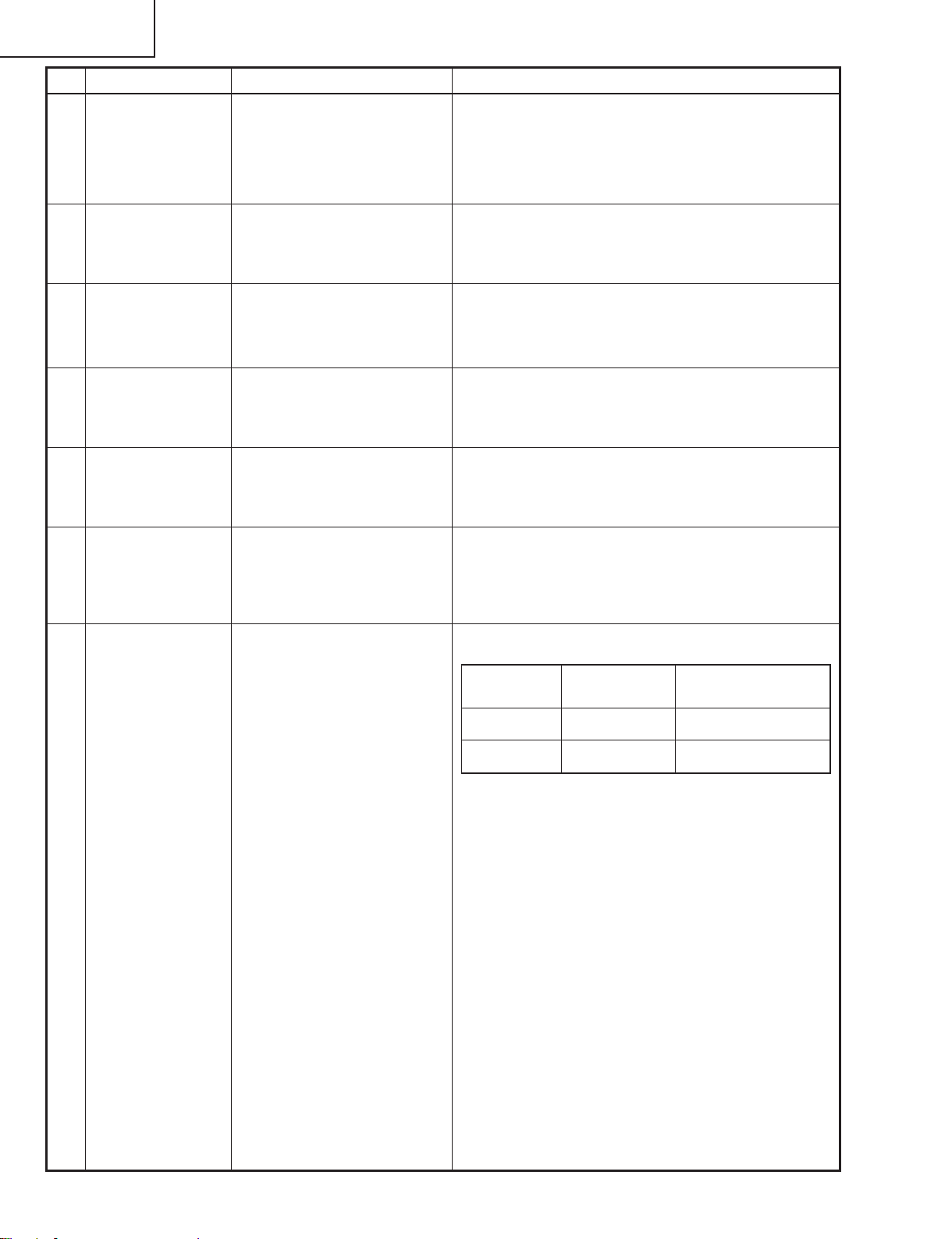
26 Delivery set-
tings
» Make the following settings.
Destination
Process adjustment Remote control adjustment
(Model)
US (XU) S4 Factory setting at 4
Europe (XE) S4 Factory setting at 4
28
Page 29
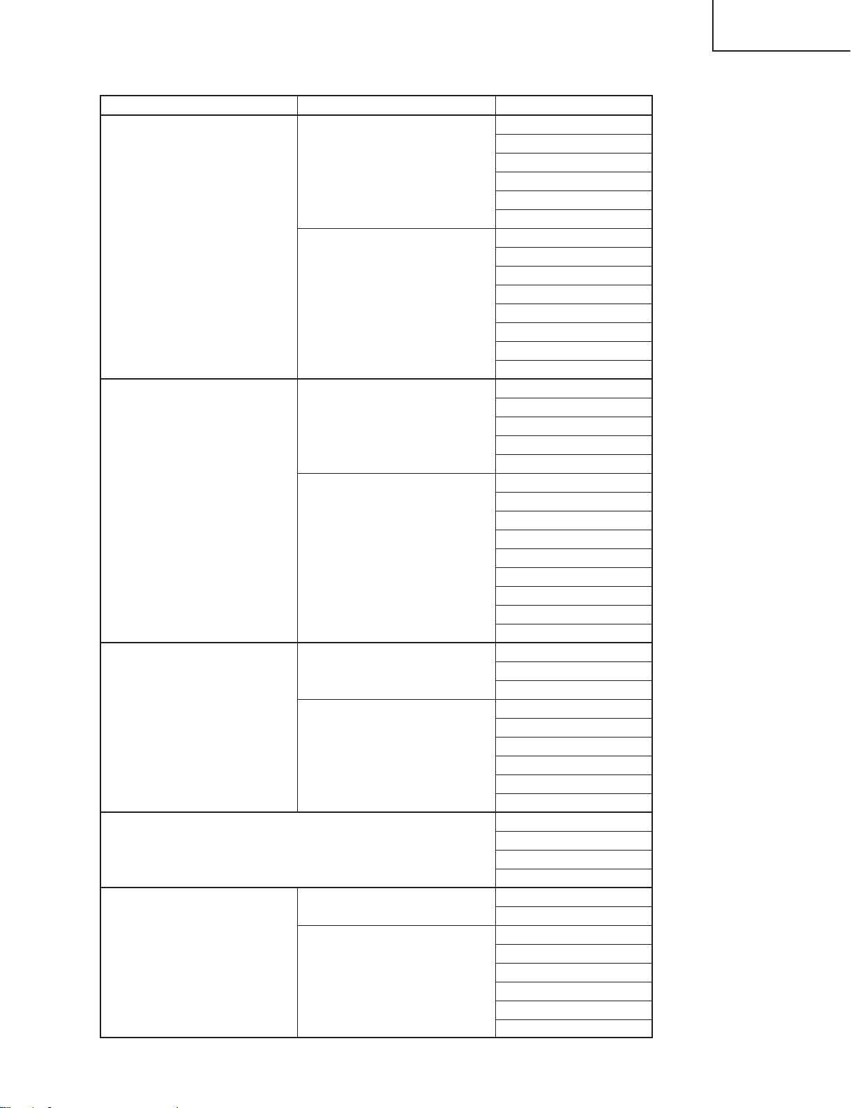
Process menu1
Group Sub group Subject
R-Bright
R-Contrast
AD
Adjust PC Image
CXA2111R
VPC3230 Color
Adjust VIDEO Image
CXA2111R AMP-B-BLK
VPC3230 Contrast
Adjust Component (480I) AMP-G-Gain
CXA2111R
LCD5(CXA1839)(480P)
(The menu appears on the screen. But do not use this menu because
this model is not equipped with the DTV function.)
NRS
LCD2 (6050)
COM
G-Bright
G-Contrast
B-Bright
B-Contrast
AMP-R-BLK
AMP-R-GAIN
AMP-G-BLK
AMP-G-GAIN
AMP-B-BLK
AMP-B-GAIN
AMP-BLK
AMP-GAIN
Bright
Contrast
H-Position
AGC
AMP-R-BLK
AMP-R-Gain
AMP-G-BLK
AMP-G-Gain
AMP-B-Gain
CLPLVL
PRGLEV
SIDLEV
Bright
Color
AMP-R-Gain
AMP-B-Gain
AMP-R-BLK
AMP-G-BLK
AMP-B-BLK
DTV_Bright
DTV_Contrast
DTV_Color
DTV_Tint
NRS-H
NRS-L
R_LCCOM
G_LCCOM
B_LCCOM
R_REVLCCOM
G_REVLCCOM
B_REVLCCOM
PG-C20XU
PG-C20XE
AN-Z7T
29
Page 30
PG-C20XU
PG-C20XE
AN-Z7T
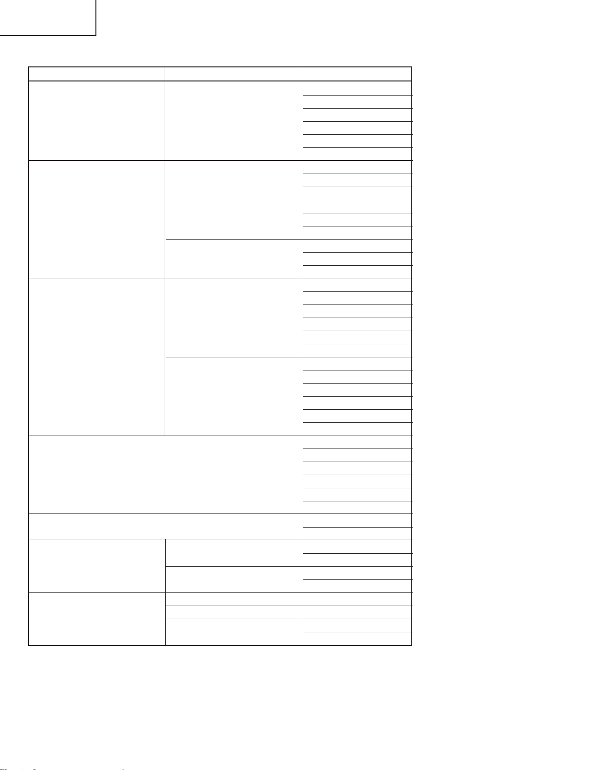
Process menu2
Group Sub group Subject
R_CLDLY
G_CLDLY
LCD2 (6050) CLDLY
GHOST B_GHOST
LCD3 (Adjust GA4) G_GHOST_W
CK-PHASE GCK-PHASE
Adjust Horz. Conv
LCD4 (Adjust Conv)
Adjust Vert. Conv
Version
SS
Temp
Temp/Fan State
Fan Speed
Gamma Off on/off
Option
Revise Color Uneven on/off
EEPROM Initialize
B_CLDLY
R_REVCLDLY
G_REVCLDLY
B_REVCLDLY
R_GHOST
G_GHOST
R_GHOST_W
B_GHOST_W
RCK-PHASE
BCK-PHASE
R_HCONV
G_HCONV
B_HCONV
R_REVHCONV
G_REVHCONV
B_REVHCONV
R_VCONV
G_VCONV
B_VCONV
R_REVVCONV
G_REVVCONV
B_REVVCONV
Boot Code
Config
Sharp Table
Rom Code
GUI
Sub CPU
S4
S5
Inside Temp/ref
Outside Temp/ref
Lamp Fan
Other Fan
Cancel
Initialize Start
30
Page 31

YES
YES
NO
Checking the basic
performance
Is the POWER LED on or
flickering in red or green?
Go to "Checking the
power unit"
Go to "Checking the lamp
light-up"
NO
Is the set turned on by the
set’s or remote controller’s
power key?
Go to "Checking the
microcomputer
peripherals" and
"Checking the PLL circuit"
NO
Go to "Checking the
output line"
Go to "Checking the RGB
input"
Go to "Checking the
component input"
Go to "Checking the
video input"
Go to "Checking the
audio input"
Go to "Checking the RS232C"
End
NO
Is the cooling fan
running? Is the lamp on?
Is the user menu
displayed?
YES
YES
PG-C20XU
PG-C20XE
AN-Z7T
TROUBLE SHOOTING TABLE
31
Page 32

PG-C20XU
PG-C20XE
AN-Z7T
Checking the power unit
Are the connectors CN751,
P1707 and P3701 inserted
completely?
YES
Is the lamp cover closed
completely?
YES
Is the bimetal switch off?
YES
Is AC voltage (100-240V)
applied between pins (1)
and (3) of CN703?
YES
NO
Insert the connectors
CN751, P1707 and
P3701 tightly?
NO
Close the lamp cover
tightly.
NO
Replace the bimetal
NO
Replace F701.
Disconnect the CN751
connector (EA). Is there
13V output at pins (7), (8)
and (9)?
YES
Check the output PWB for
short-circuit. Check also
the UNT3701 on the
connection terminal PWB
and its peripheral circuits.
NO
Check Q706, Q708 and
Q710 for damage.
Replace as required.
32
Page 33

YES
YES
YES
YES
YES
YES
YES
NO
Checking the
microcomputer
peripherals
Is a voltage of about 3V
applied to pin (33) (RCS)
of IC1601?
Check the intake filter
cover for poor fitting and
the cooling fan for trouble.
Check IC1601, IC1606 and
their peripheral circuits.
Is the signal level at pin
(7) of IC8037 about 0V?
End
End
Set SW1602 to
"NORMAL" position.
NO
Is SW1602 set at
"NORMAL" position?
NO
NO
Check IC8018, IC8019,
IC8020 and their peripheral
circuits as well pin (26) of
IC1601 and its peripheral
circuits.
Check IC8021 and
IC8022. Replace the PC
interface as required.
NO
NO
Check all the ICs
connected with the
SDA3/SCL3 and
SDA5/SCL5 lines.
NO
Is there pulse signal at
pin (64) of IC1601?
Is there pulse signal at pin
(1) of IC1601?
Is there signal at pins (1),
(3), (4) and (6) of IC1802?
Check all the signals (A1
thru A17 and D1 thru D15)
of IC8021 with oscilloscope.
Are signal levels 0V and
3V?
PG-C20XU
PG-C20XE
AN-Z7T
33
Page 34

PG-C20XU
PG-C20XE
AN-Z7T
Checking the PLL circuit
Is there 120MHz clock
output at pin (8) of
IC8001?
YES
Is there 40MHz clock
output at pin (9) of
IC8001?
YES
Is there 16MHz or so
clock output at pin (7) of
IC8001?
YES
End
Checking the lamp
light-up
NO
NO
NO
IC8001 or its peripheral
circuit defective.
Turn on the power switch.
Is discharge sound heard
from the lamp?
NO
Are DC260-400V voltages
applied between the pins
of PL connector?
YES
Is the BA harness tightly
inserted? Is the harness
broken?
YES
Is voltage of over 1V
applied between pins (1)
and (2) of BA harness?
YES
YES
NO
NO
NO
Is the lamp socket
disconnected?
YES
Reconnect the lamp
socket tightly.
Go to "Checking the
power unit".
Insert the BA harness
tightly. Or replace it as
required.
Go to "Checking the
microcomputer
peripherals".
NO
Replace the lamp.
Replace the ballast unit.
34
Page 35

Checking the output line
PG-C20XU
PG-C20XE
AN-Z7T
Are there video input signals at
TP1401, TP1402 and TP1403?
YES
Are there video output signals at
pins (14), (16) and (18) of IC1405?
YES
Are there video input signals at pins
(45) of IC1101, IC1201, IC1301,
IC1102, IC1202 and IC1302?
YES
NO
Check P8001 and SC1701 for solder
cracks.
Are there video output signals at pins
(42), (44) and (46) of IC8024?
NO
Are there digital input signals at pins
(1) thru (33) of IC8024?
NO
IC8023 defective. Replace the PC
interface.
NO
Check IC1405, IC1403 and their
peripheral circuits.
Check IC1102, IC1202, IC1302 and
NO
their peripheral circuits as well as
pins (35) and (36) and the 15.5V
power line.
YES
YES
Check Q8013, Q8014,
Q8015 and their
peripheral circuits.
Check IC8024 and
IC8025.
Are there clock input signals (MCLK) at
pins (54) and (55) of IC1102, IC1202
NO
and IC1302?
YES
Are there output signals at pins (17),
(19), (21), (28), (30) and (32) of IC1101,
NO
IC1201, IC1301, IC1102, IC1202 and
IC1302?
YES
Are signals going to the control signal
NO
lines at pins (3) thru (21) of IC1103,
IC1203 and IC1303?
YES
Are signals coming from the control signal
lines at pins (11) thru (17) of IC1402 and
NO
IC1404?
YES
Are there input signals at SC1101,
NO
SC1201 and SC1301?
YES
Check the R, G and B panels.
Check P8001 and SC1701 for solder
cracks, and go to "Checking the
digital signal processing circuit".
Check IC1101, IC1201, IC1301,
IC1102, IC1202, IC1302, IC1401,
IC1403, IC1405 and their peripheral
circuits.
Check P8001 and SC1701 for solder
cracks, and go to "Checking the
digital signal processing circuit".
Check IC1402, IC1404 and their
peripheral circuits.
Check SC1101, SC1202, SC1301
and their peripheral circuits.
IC8023 defective.
Replace the PC
interface.
IC8023 defective.
Replace the PC
interface.
35
Page 36

PG-C20XU
PG-C20XE
AN-Z7T
1
2
Checking the RGB input
Feed the sync separation RGB
signal to INPUT1 terminal (pin
(15) of D-SUB).
Select INPUT1 (RGB) with the
set’s control or remote control
button.
Is the image disturbed? Does
NO SIGANL indication
appear?
YES
Do R, G and B colors appear?
YES
Does an image appears?
NO
Is the contour as specified?
YES
Are there disturbing vertical
stripes?
NO
Go to "Checking the sync signal".
NO
Go to "Checking the RGB input".
YES
Go to "Checking the input signal
setting input".
NO
YES
End
NO
IC8026 or peripheral circuit
defective.
36
Page 37

YES
YES
Checking the input signal
setting
Is the input signal setting
as specified?
Select the specified signal.
Is the connector properly
connected?
NO
Reconnect the connector.
End
NO
1
2
YES
YES
YES
YES
Checking the sync signal
Is there vertical sync signal
at TP8003?
Is there horizontal sync
signal at pin (3) of IC3008
connection terminal PWB?
IC3008 or its peripheral
circuit defective. Or
SC3003 in poor contact.
Is there horizontal sync
signal at pin (3) of IC3006
connection terminal PWB?
IC3006, IC3010 or their
peripheral circuit defective.
Or SC3003 in poor
contact.
Is there horizontal sync
signal at TP8002?
NO
End
SC3001 or its peripheral
circuit defective.
NO
NO
NO
PG-C20XU
PG-C20XE
AN-Z7T
37
Page 38

PG-C20XU
PG-C20XE
AN-Z7T
Checking the RGB signal
In order to check the input
signal, set the signal
generator to the gradation
signal.
Using the oscilloscope,
measure the lands (R, G
and B inputs of IC8026) of
C8204, C8208 and C8213.
Are there specified
NO
YES
IC8026 or its peripheral
circuit defective.
Are there gradation signals
at pins (8), (10) and (12) of
IC8012?
YES
IC8012 or its peripheral
circuit defective.
NO
Are there gradation signals
at pins (16), (18) and (20)
of IC3002 connection
terminal PWB?
YES
IC3002 or its peripheral
circuit defective. Or
SC3003 in poor contact.
NO
SC3001 or its peripheral
circuit defective.
38
Page 39

NO
YES
YES
Checking the SOG circuit
Using the oscilloscope,
measure the land of R8231
(pin (32) of IC8026). Is
there composite sync
signal?
NO
Using the oscilloscope,
measure the land of R8110
(base of Q8010). Does the
video signal contain the
sync signal?
Is there video signal with
sync signal at pin (18) of
IC3002 connection
terminal PWB?
NO
IC3002 connection
terminal PWB or its
peripheral circuit defective.
IC8008, IC8009, IC8031 or
their peripheral circuit
defective.
YES
SC3003 or its peripheral
circuit defective.
End
YES
NO
NO
YES
YES
NO
Checking the video input
Feed the specified video
signal.
Is there video signal at pin
(73) of IC8003?
Go to "Checking the
video sync signal".
Is there video signal at pin
(7) of IC3403 connection
terminal PWB?
IC3403 or its peripheral
circuit defective. Or
SC3003 in poor contact.
Is the image disturbed?
Does an image appear?
Are the colors as
specified?
End
IC8003 or its peripheral
circuit defective.
J3303 or its peripheral
circuit defective.
Select VIDEO with the
set’s key or remote control
button.
NO
NO
YES YES
PG-C20XU
PG-C20XE
AN-Z7T
39
Page 40

PG-C20XU
PG-C20XE
AN-Z7T
Checking the video sync
signal
Using the oscilloscope,
measure the signal at
TL8006. (Check the
vertical sync signal.)
Is the vertical sync signal
as specified?
YES
Using the oscilloscope,
measure the signal at
TL8009. (Check the
horizontal sync signal.)
Is the horizontal sync
signal as specified?
YES
Is there 15kHz or so signal
at TP8007?
YES
NO
NO
NO
Go to "Checking the input
signal setting".
If out of spec again,
IC8003 or its peripheral
circuit defective.
Is there signal with half the
vertical frequency at
TP8010?
YES
Is there 27MHz or so clock
signal at FL8034?
YES
Is there 13.5MHz or so
clock signal at FL8034?
YES
End
NO
NO
NO
IC8003 or its peripheral
circuit defective.
40
Page 41

Checking the digital signal
processing circuit
PG-C20XU
PG-C20XE
AN-Z7T
Is there 40MHz or so clock
signal at FL8024?
YES
Is there 38kHz or so pulse
(sync) signal at FL8026?
YES
Is there 60Hz or so pulse
(sync) signal at FL8025?
YES
End
NO
NO
NO
Go to "Checking the PLL
circuit".
IC8022, IC8021 or their
peripheral circuit defective.
41
Page 42

PG-C20XU
PG-C20XE
AN-Z7T
Checking the audio
signal
Are there audio output
signals at pins (7) of
IC3301 and IC3302?
YES
Is voltage applied to pin (4)
of IC1901?
YES
Using the remote control,
change VOL and cancel
MUTE. Does the voltage at
pin (7) of IC1901 vary
accordingly?
YES
Is there audio output signal
at pin (5) of IC1901?
YES
NO
NO
NO
NO
Check the audio cable.
Switch IC3301 and IC3302
to each other to check the
peripheral circuits.
Check R1914 first and
then the power circuit.
Check IC1403, IC1605 and
their peripheral circuits.
Check IC1901 and its
peripheral circuits.
Check the SP connector.
Checking the RS-232C
Using the communication
software ("TERA TERM"
recommended), make the
following settings:
Baud rate: 9600 bps
Bit length: 8 bits
Stop bit: 1 bit
Parity: None
Press the RETURN key on
the keyboard. Does "ERR"
reappear?
YES
NO
Check IC3601, IC1606,
IC1601, SW1602, IC8022,
communication circuit and
their peripheral circuits.
End
42
Page 43

Technische Daten
Produkttyp LCD Projector
Modell PG-C20XU/XE
Videosystem PAL/PAL 60/PAL-M/PAL-N/SECAM/NTSC 3.58/NTSC 4.43/DTV 480P
Wiedergabeverfahren LCD-Projektionspaneel x 3,optisches RGB-Verschlußverfahren
LCD-Projektionspaneel Panelgröße:22,9 mm (0,9") (13,9 mm [H ] x 18,5 mm [B ])
Wiedergabe-Verfahren:Durchl ä ssiges TN-Flüssigkristall-Paneel
Treiberverfahren:TFT (Dünnfilmtransistor) Aktivmatrix-Paneel
Anzahl der Bildpunkte:786.432 Bildpunkte (1.024 [H ] x 768 [V ])
Objektiv 1 –1,2 Zoomobjektiv, F2,3 –2,6, f =36,0 –43,2 mm
Projektionslampe 150 W Gleichstrom-Lampe
Kontrastverh ä ltnis 500:1
Videoeingangssignal RCA-Stecker:VIDEO, Gemischtes Video, 1,0 Vs-s, negatives Sync.-Signal, 75 Ω terminiert
RCA-Stecker:AUDIO, 0,5 Vrms mehr als 22 kΩ (Stereo)
S-Videoeingangssignal 4-Pin Mini DIN-Stecker
Y (Luminanz-Signal):1,0 Vs-s,negatives Sync.-Signal, 75 Ω terminiert
C (Chrominanz-Signal):Stoß 0,286 Vs-s, 75 Ω terminiert
Horizontale Aufl ö sung 580 Fernsehzeilen (Videoeingang)
Audioausgang 1,0 W (monaural)
RGB-Computereingangssignal 15-PIN MINI D-SUB STECKANSCHLUSS (Computer-Eingangsport 1 (COMPUTER INPUT 1),
Computer-Ausgangsport für Eingangs-Port 1 (COMPUTER OUTPUT für INPUT 1):
RGB getrennt/gemischte Sync./Sync.auf Grün-Typ analoger Eingang:0 –0,7 Vs-s,
positiv,75 Ω terminiert
STEREO-MINIBUCHSE:AUDIO,0,5 Vrms,mehr als 22 kΩ (Stereo)
HORIZONTALES SYNC.-SIGNAL:TTL-Pegelsignal (positiv/negativ)oder gemischtes Sync.-
Signal (nur Macintosh)
VERTIKALES SYNC.-SIGNAL:Wie oben
Punktetakt 12 –108 MHz
Vertikale Frequenz 43 –85 Hz
Horizontale Frequenz 15 –80 kHz
Computereingangs-Signal 9-Pin Mini DIN-Steckanschluß (RS-232C-Anschlußstelle)
Lautsprechersystem 2,8 cm (1 7 ⁄64" ) rund
Nennspannung 100 –240 V Wechselstromspannung
Eingangsspannung 2,6 A
Nennfrequenz 50/60 Hz
Nennaufnahme 230 W (Wahl von "OFF" im "Energiespar-Modus".)
200 W (Wahl von "ON" im "Energiespar-Modus".)
Betriebstemperatur +5°C bis +35°C
Lagertemperatur −20°C bis +60°C
Geh ä use Kunststoff
I/R-Tr ä gerfrequenz 38 kHz
Abmessungen (ca.) 260 x 74 x 207 mm (B x H x T) (nur Hauptgerät)
260 x 82 x 207 mm (B x H x T) (einschlie ß lich Drehfüße und vorstehende Teile)
Gewicht (ca.) 2,6 kg
Mitgeliefertes Zubehör Fernbedienung, Zwei Batterien der Größe AAA,Netzkabel (3,6 m), RGB-Computerkabel (3 m),
Computer-Audiokabel (3 m), PS/2-Maus-Steuerungskabel (1 m), USB-Maus-Steuerungskabel (1,5
m), DIN-D-Sub RS-232C-Kabel (15 cm), Fernbedienungs-Mausempfänger, Ersatz-Luftfilter,
Objektivkappe (angebracht), Objektivkappenband, CD-ROM, Bedienungsanleitung für LCDProjektor, Kurzanleitungen für den LCD-Projektor
Ersatzteile Lampensatz (Lampe/Käfigmodul)(BQC-PGC20X//1), Fernbedienung (RRMCG1613CESA),
Batterien der Größe AAA,Netzkabel (CACCU5013DE01 (PG-C20XU), QACCV4002CEZZ (PGC20XE), QACCB5024CENA (PG-C20XE)), RGB-Computerkabel (QCNWG0002EZZ), Computer-Audiokabel (QCNW-4870CEZZ), PS/2-Maus- Steuerungskabel (QCNW-5113CEZZ), USBMaus-Steuerungskabel (QCNW-5680CEZZ), DIN-D-Sub RS-232C-Kabel (QCNW-5288CEZZ),
Fernbedienungs-Mausempfänger (RUNTK0694CEZZ), Luftfilter (PFILD0123CEZZ), Objektivkappe
(PCOVZ1095CEKA), Objektivkappenband (UBNDT0013CEZZ), CD-ROM (UDSKA0029CEN1
(PG-C20XU), UDSKA0048CEN1 (PG-C20XE)), Bedienungsanleitung für LCD-Projektor (TINS7204CEZZ (PG-C20XU), TINS-7271CEZZ (PG-C20XE)), Kurzanleitungen für den LCD-Projektor
(TINS-7205CEZZ (PG-C20XU), TINS-7272CEZZ (PG-C20XE), TINS-7284CEZZ (PG-C20XE),
TINS-7285CEZZ (PG-C20XE))
Dieser Projektor von SHARP ist mit 3 LCD-(Flüssigkristallanzeige)
Projektionspaneels ausgestattet. Diese neuartigen Projektionspaneels
enthalten TFTs (Dünnfilmtransistoren) mit insgesamt 786.432
Bildpunkten (x RGB). Bei allen technologisch fortschrittlichen,
elektronischen Geräten, z.B.Großbild-Fernsehern, Videosystemen bzw.
Videokameras,sind bestimmte Toleranzgrenzen für die Funktionen
gegeben.
Ä nderungen der technischen Daten ohne vorherige Ank ü ndigung vorbehalten.
Dieses Gerät hat einige inaktive,innerhalb akzeptierter T oleranzgrenzen
liegende TFTs, die als beleuchtete oder als nicht aktive Punkte auf der
Bildwand wiedergegeben werden. Dies hat keinen Einfluß auf die
Bildqualität und die Lebensdauer des Gerätes.
PG-C20XU
PG-C20XE
AN-Z7T
43
Page 44

PG-C20XU
5
5
PG-C20XE
AN-Z7T
HINWEIS FÜR DAS
WARTUNGSPERSONAL
234567890123456789012345678901212345678901234
ACHTUNG: UV-STRAHLUNG
234567890123456789012345678901212345678901234
Die Beleuchtungsquelle des LCD-Projektors, eine
UHP-Lampe, emittiert eine geringe Menge
UV-Strahlung.
DIREKTE BESTRAHLUNG AUF AUGEN
UND HAUT MUSS VERMIEDEN WERDEN.
Zur Gewährleistung der Sicherheit muß folgendes
beachtet werden:
1. Bei Arbeiten am Projektor bei eingeschalteter
Lampe und abgenommenem oberen Gehäuse muß
unbedingt eine Sonnenbrille getragen werden.
Auswechseln der Lampe
Hinweis:
Da die Lampe während des Betriebs sehr heiß wird,
sollte die Lampe erst ausgewechselt werden, nachdem
das Gerät mindestens eine Stunde ausgeschaltet war ,
damit die Lampe ausreichend abkühlen kann.
Beim Installieren der neuen Lampe muß darauf
geachtet werden, die Lampe selbst (Glaskolben)
nicht zu berühren. Vielmehr muß die Lampe am
Reflektor 2 gehalten werden.
[Es darf nur ein Original-Ersatzteil verwendet
werden.]
Lampe
1
Reflektor
2
2. Die Lampe darf nicht außerhalb des
Lampengehäuses eingeschaltet werden.
3. Betrieb für länger als 2 Stunden bei
abgenommenem Gehäuse ist nicht zulässig.
Zur Beachtung bei UV-Strahlung
und Mitteldruck-Lampen
1. Vor dem Auswechseln der Lampe muß der
Netzstecker gezogen werden.
2. Vor Durchführung von Wartungsarbeiten muß das
Gerät eine Stunde abkühlen.
3. Die Lampe darf nur gegen eine der gleichen Art
ausgewechselt werden. T yp BQC-PGC20X//1,
bemessen für 100 V/200 W.
4. Die Lampe gibt eine geringe UV-Strahlung ab,
daher muß direkter Augenkontakt vermieden
werden.
5. Die Mitteldruck-Lampe weist ein Explosionsrisiko
auf. Daher müssen die nachstehenden
Installationsanweisungen beachtet werden, und die
Lampe muß vorsichtig behandelt werden.
GEFAHR! — Niemals die Spannungsversorgung
einschalten, ohne daß eine Lampe vorhanden ist,
um elektrische Schläge und Schäden am Gerät zu
vermeiden, da der Stabilisator anfangs hohe
Spannungen erzeugt.
Da eine geringe Menge UV-Strahlung an der Öf fnung
zwischen den Lüftern austritt, wird empfohlen,
während der Wartungsarbeiten die Abdeckkappe des
Zusatzobjektivs an dieser Öffnung anzubringen, um
Augen und Haut vor den UV-Strahlen zu schützen.
44
Page 45

Lage der Bedienelemente
Projektor
Ansicht von vorne und oben
PG-C20XU
PG-C20XE
AN-Z7T
Betriebs-Taste (ON/OFF)
Betriebs-anzeige
Eingang-/Zur ü ck-Taste
(INPUT/BACK)
Trapezverzeichnungs-/
Einstellungs-Tasten
(KEYSTONE/ ]/[)
Zoom-Knopf
Fokussierring
Kühlventilator (Luftauslaß)
Drehfuß-Feststeller
Seiten-und Rückansicht
ON/OFF
POWER
KEYSTONE
INPUT
BACK ENTER MENU
LAMP
TEMP.
AUTO SYNC
Lampenaustausch-Anzeige
Temperaturwarnanzeige
Automatische
Synchronisierung-/EingabeTaste (AUTO SYNC/ENTER)
Menü-Taste (MENU)
Luftfilter/Kühlventilator
(Lufteinlaß)
Lautsprecher
Fernbedienungs-Sensor
Öffnung für
Objektivkappenband
Standardanschluß für
KensingtonSicherheitssperre
S-Videoeingangsanschlu ß 2
(4-Pin Mini DIN)
(S-VIDEO INPUT 2)
Videoeinganganschluß 3
(RCA) (VIDEO INPUT 3)
Audioeingangsanschlüsse
(RCA) (AUDIO INPUT)
RS-232C-Anschlußstelle
(9-Pin Mini DIN)
S-VIDEO VIDEO
AUDIO INPUTINPUT 3INPUT 2
(S-VIDEO, VIDEO INPUT)
LR
RS-232C
INPUT 1
COMPUTER COMPUTERAUDIO AUDIO
OUTPUT
Steckanschluß
Fernbedienungs-Sensor
(INPUT 1)
Computer-Ausgangsport für
Eingangs-Port 1 (HD 15)
(COMPUTER OUTPUT für INPUT 1)
Audioausgangsanschluß für EingangsPort 1 (3.5 mm stereo minijack)
(AUDIO OUTPUT für INPUT 1)
Computer-Eingangs-Port 1
(HD 15)(COMPUTER INPUT 1)
Audioeingangsanschluß 1
(3,5 mm Stereo-Minibuchse)
(AUDIO INPUT 1)
45
Page 46

PG-C20XU
PG-C20XE
AN-Z7T
Fernbedienung
Vorderansicht
Maus-(]/[)/
Einstellungs-(]/[)
Tasten
Maustaste (< )
MAUS-Taste
(MOUSE)
Standbild-Taste
(FREEZE)
Menü-Taste
(MENU)
Eingangs-Taste
(INPUT)
Trapezverzeichnungs-
Tasten (KEYSTONE)
Lautstärke-Tasten
(+/−)
Maustaste (> )
Netz-Taste
(POWER)
Rechte Klick-/
Eingabe-Taste
(R-CLICK/ENTER)
Vergrößern-Taste
(ENLARGE)
Auto-Synchron-Taste
(AUTO SYNC)
AV-StummschaltungsTaste (AV MUTE)
Größe-Taste (RESIZE)
GAMMA-Taste
Ansicht von hinten
Linke Klick-/
Zurück-taste
(L-CLICK/
BACK)
Öffnen der Abdeckung
Abdeckung
Einsetzen der Batterien
Auf den Vorsprung
1
drücken und die
Batteriefachabdeckung in
Pfeilrichtung öffnen.
• Wenn die Fernbedienung naß wird, sollte sie sofort trocken gewischt werden.
• Die Fernbedienung sollte nicht übermäßiger Wärme oder Feuchtigkeit ausgesetzt werden.
• Wenn die Fernbedienung für längere Zeit nicht verwendet wird, sollten die Batterie entfernt werden.
• Niemals neue und alte Batterien oder verschiedene Batterietypen mischen.
• Einige Bedienvorgänge können nur mit der Fernbedienung ausgef ührt werden. Die Fernbedienung sor gfältig behandeln.
Zwei Batterien der Größe
2
AAA einlegen und
sicherstellen, daß die Pole
mit der + und −
Markierung im Batteriefach
übereinstimmen.
Die Vorsprünge auf dem
3
Ende der
Batteriefachabdeckung in
die Schlitze schieben und
die Abdeckung auf das
Batteriefach drücken.
46
Page 47

Positionierung der Fernbedienung bzw. des Mausempfängers
Die Fernbedienung kann zur Steuerung des Projektors innerhalb des unten gezeigten Bereiches verwendet
werden.
Der Fernbedienungs-Mausempfänger kann mit der Fernbedienung zusammen zur Steuerung der Mausfunktion
eines angeschlossenen Computers innerhalb des unten gezeigten Bereiches verwendet werden.
Das Signal der Fernbedienung kann für einen einfacheren Betrieb von der Bildwand reflektiert werden. Der wirksame
Abstand des Signals kann aufgrund des Materials der Bildwand unterschiedlich sein.
PG-C20XU
PG-C20XE
AN-Z7T
Steuerung des Projektors
Fernbedienung
7 m
30
45
30
45
30
Fernbedienung
Verwendbare Tasten in der MOUSE-Betriebsart
Fernbedienung
(Ansicht von vorne)
Maus
MOUSE
R-CLICK
Verwendung der drahtlosen Maus
Fernbedienung
30
30
120
4 m
FernbedienungsMausempfänger
Verwendung als eine drahtlose Maus
Beim Drücken von MOUSE leuchten die Tasten auf
der Fernbedienung auf und die Fernbedienung wird
auf die MOUSE-Betriebsart eingestellt.
Während der MOUSE-Betriebsart kann der Cursor als
Zeiger verwendet werden. Die MOUSE-Betriebsart
wird etwa 10 Sekunden während des Aufleuchtens
der Tasten eingestellt.
Beim Drücken von MENU oder ENLARGE wird die
MOUSE-Betriebsart beendet und die normale
Betriebsart wieder eingestellt.
Sicherstellen, daß der mitgelieferte FernbedienungsMausempfänger am Computer angeschlossen ist.
Fernbedienung
(Ansicht der Rückseite)
AV MUTE
L-CLICK
Die drahtlose Maus kann nicht richtig funktionieren, wenn
der serielle Port des Computers nicht richtig eingestellt ist.
Siehe die Bedienungsanleitung des Computers für Hinweise
zur Einstellung bzw. Installation des Maustreibers.
Für eintastige Systeme kann sowohl L-CLICK als auch R-
CLICK verwendet werden.
47
Page 48

PG-C20XU
PG-C20XE
AN-Z7T
Pin-Belegung
Computer-Eingangsport 1 (COMPUTER INPUT 1): 15-Pin Mini-D-Sub-Buchse
Computereingang
Analog
1. Videoeingang (rot)
2. Videoeingang
5
10
15
1
6
11
RS-232C-Anschlußstelle: 9-Pin D-Sub-Stecker des DIN-D-Sub RS-232C-Kabels
Pin Nr. Signal Name E/A Referenz
5
1
9
6
1 Nicht angeschlossen
2 RD Daten empfangen Eingang An internen Schaltkreis angeschlossen
3 SD Daten senden Ausgang An internen Schaltkreis angeschlossen
4 Nicht angeschlossen
5 SG Signalerdung An internen Schaltkreis angeschlossen
6 Nicht angeschlossen
7 Nicht angeschlossen
8 Nicht angeschlossen
9 Nicht angeschlossen
(Grün/Sync. auf Grün)
3. Videoeingang (blau)
4. Nicht belegt
5. Gemischtes Sync.-Signal
6. MASSE (rot)
7. MASSE (Grün/Sync. auf Grün)
8. MASSE (blau)
9. Nicht belegt
10. Nicht belegt
11. MASSE
12. Bi-direktionale Daten
13. Horizontales Sync.Signal
14. Vertikales Sync.-Signal
15. Daten-Zeitgeber
RS-232C-Anschlußstelle: 9-Pin Mini DIN-Steckanschluß
8
9
7
6
5
4
21
Pin Nr. Signal Name E/A Referenz
1 Nicht angeschlossen
2 RD Daten empfangen Eingang An internen Schaltkreis angeschlossen
3 SD Daten senden Ausgang An internen Schaltkreis angeschlossen
4 Nicht angeschlossen
3
5 SG Signalerdung An internen Schaltkreis angeschlossen
6 Nicht angeschlossen
7 Nicht angeschlossen
8 Nicht angeschlossen
9 Nicht angeschlossen
48
Page 49

Abmessungen
PG-C20XU
PG-C20XE
AN-Z7T
Ansicht der Rückseite
Ansicht von oben
Seitenansicht
260
207
32
Ansicht von vorne
82
42
58118
8
169,5
Anhang Ansicht von unten
49
Einheit:mm
Page 50

PG-C20XU
PG-C20XE
AN-Z7T
ENTFERNEN DER HAUPTTEILE
1.Abnehmen der Einlaßabdeckung und der Lampen-Einheit.
1-1. Die Einlaßabdeckung abnehmen.
1-2. Die Halteschraube aus der Lampenabdeckung herausdrehen, dann die Lampenabdeckung abnehmen.
1-3. Die beiden Halteschraube aus der Lampen-Einheit herausdrehen, dann die Lampen-Einheit ausbauen.
1-3
1-1
Einlaßabdeckung
1-3
Lampen-Einheit
Lampenabdeckung
1-2
50
Page 51

2.Abnehmen der vorderen und oberen Verkleidungen
2-1. Die drei Halteschrauben (silberfarben) aus der vorderen Verkleidung herausdrehen.
2-2. Die sieben Halteschrauben (silberfarben) aus der oberen Verkleidung herausdrehen.
2-2
2-2
2-2
2-2
PG-C20XU
PG-C20XE
AN-Z7T
2-1
2-3. Die mit ∗ markierten Stellen der oberen Verkleidung nach unten drücken, um die Haken zu lösen; danach die
obere Verkleidung abnehmen.
2-4. Die obere Verkleidung vorsichtig anheben, die Stecker von der Steuertafel und dem Lautsprecher abziehen,
dann die obere Verkleidung nach oben abnehmen.
Oberen Verkleidungen
2-4
2-3
Vorderen Verkleidungen
51
Page 52

PG-C20XU
PG-C20XE
AN-Z7T
3. Ausbau der Platine-Ausgabeeinheit, des Fernbedienungs-Sensors, der
Platine-Empfängereinheit für die Fernbedienung und der Lüfter-Einheit
3-1. Die fünf Halteschrauben (gelb) aus der Platine-Ausgabeeinheit herausdrehen.Die Massefeder und die
elektrostatische Schutzfolie entfernen.
3-2. Die Platine-Ausgabeeinheit anheben, die Stecker abziehen, dann die Platine-Ausgabeeinheit herausheben.
3-3. Die beiden Halteschrauben (schwarz) aus der Ansaug-Lüftereinheit herausdrehen, dann die
Ansaug-Lüftereinheit und den Temperatursensor ausbauen.
3-4. Die Haken der Ansaug-Lüftereinheit von der Fernbedienungsempfänger-Platineneinheit lösen, dann diese
Baugruppe herausnehmen.
3-1
Massefeder
3-1
Elektrostatische Schutzfolie
(PG-C20XU)
(P1702)
Temperatursensor
(P1707)
(P1703)
PlatineAusgabeeinheit
(P1705)
(P1708)
(P1706)
(SC1102)
(P1704)
(P1602)
(P1701)
(SC1202)
(SC1302)
PlatineFernbedienungsempfängerseinheit
3-3
(P1601)
3-2
3-4
Lüfter-Einheit
52
Page 53

PG-C20XU
PG-C20XE
AN-Z7T
4.Ausbau der vorderen Luftführungseinheit, PC-I/F-platine und der
Optik-Einheit
4-1. Die Halteschraube (silberfarben) aus dem Bimetall herausdrehen, dann das Bimetall abnehmen.
4-2. Die beiden Halteschrauben (eine schwarze und eine silberfarbene) aus der vorderen Luftführungseinheit
herausdrehen, dann die vordere Luftführungseinheit ausbauen.
4-3. Die beiden Halteschrauben (gelb) aus der PC-I/F-platine herausdrehen. Die PC-I/F-platine von oben
herausnehmen.
4-4. Die beiden Halteschrauben (silberfarben) aus dem Lampenfassungshalter herausdrehen, dann den
Lampenfassungshalter ausbauen.
4-5. Die vier Halteschrauben (zwei schwarze und zwei gelbe) aus der Optik-Einheit herausdrehen, dann die
Optik-Einheit von oben herausnehmen.
4-4
4-1
4-5
4-3
PC-I/Fplatine
4-5
4-5
Optik-Einheit
4-2
Untere Verkleidung
53
Page 54

PG-C20XU
PG-C20XE
AN-Z7T
5.Ausbau der Ballast-/Leistungs-/Netzeingangseinheit-Platine, des
Kühlgebläses und des Spannungswählschalters
5-1. Die Halteschraube (gelb oder silberfarben) aus der Ballast-Abdeckung herausdrehen. Das Teflon-Klebeband
entfernen, das zur Befestigung der Steckerkabel an der Ballast-Abdeckung dient. Die Ballast-Abdeckung
herausnehmen.
5-2. Die drei Halteschrauben (gelb oder silberfarben) aus der Ballast-Platineneinheit herausdrehen. Die Stecker
aus der Leistungs-Platineneinheit herausdrehen, dann die Ballast-Platineneinheit entfernen.
5-3. Die beiden Halteschrauben (silberfarben) aus der Kühlgebläse-/Leistungs-Platineneinheit entfernen, dann
die Kühlgebläse-Einheit ausbauen.
5-4. Die drei Halteschrauben (silberfarben) aus der Netzeingangs-/Leistungs-Platineneinheit herausdrehen. Die
Stecker des Spannungswählschalters und der Leistungs-Platineneinheit (EA) abziehen. Die
Netzeingangs-Platineneinheit, Leistungs-Platineneinheit und die Abdeckung der Leistungs-Platineneinheit
herausnehmen.
5-5. Die beiden Halteschrauben (gelb) aus dem Spannungswählschalter herausdrehen, dann den Schraube, das
Gleitstück und die Feder entfernen.
Ballastabdeckung
5-2
Kühlgebläse
Leistungsplatinen-Einheit
5-3
5-1
5-1
Teflon-Klebeband
Ballast-Platine
Hinweis: Beim Anschluß dieses Steckers besonders
vorsichtig vorgehen, da die benachbarten Teile der
()
Ballast-Platineneinheit stromführend sind.
Eingangsplatinen-Einheit
5-4
B
A
5-5
5-4
Spannungs
wählschalter
Abdeckung der
LeistungsplatinenEinheit
∗Vorsichtshinweise zum Zusammenbau
Die Hochspannungskabel ( A und B in der Abbildung) der
Lampenfassung an der Ballast-Platineneinheit dürfen nicht
mit dem Kühlgebläse in Kontakt kommen. Um dies
sicherzustellen, ist das Kabel B hinter Kabel A zu verlegen,
dann die Kabel in den Einschnitt des Kühlgebläse-Halters
einpassen.
Gleitstück
Feder
(EA)
54
Page 55

PG-C20XU
PG-C20XE
6.Ausbau der Anschlußklemmen-/ 3D Y/C-Trennplatinen-Einheit
6-1. Die beiden Halteschrauben (gelb) und die beiden Halterungen aus der Anschlußklemmen-/dreidimensionalen
Y/C-Trennplatinen-Einheit herausdrehen. Die Platineneinheit zur Seite schieben und die Anschlußklemmen
aus der Bodenplatte herausziehen.
6-2. Den Stecker (EA) von der Anschlußklemmen-Platineneinheit abziehen.
7.Ausbau der mittleren Luftführung und des PBS-Kühlgebläses
7-1. Die Halteschraube von der mittleren Luftführung herausdrehen, dann die mittlere Luftführung abnehmen.
7-2. Die Halteschraube aus dem PBS-Kühlgebläse herausdrehen, dann das Winkelstück und das PBS-Kühlgebläse
ausbauen.
6-1
7-1
Mittlere
Luftführung
7-2
(EA)
AN-Z7T
Winkelstück
PBSKühlgebläse
6-2
Anschlußklemmen-/
3D Y/C-TrennplatinenEinheit
55
Page 56

PG-C20XU
1
2
PG-C20XE
AN-Z7T
Rückstellen des Lampenbetriebszeit-Timers
● Rückstellen des Lampenbetriebszeit-Timers
Nach dem Auswechseln der Lampe muß der Lampenbetriebszeit-Timer entsprechend den nachfolgenden
Anweisungen zurückgestellt werden.
● Lichtquelle (Lampe)
Die als Lichtquelle verwendete Lampe weist eine Lebensdauer von ungefähr 1000 Stunden auf. Nachdem die
Gesamtbetriebszeit mehr als 900 Stunden beträgt, muß die Lampe so bald wie möglich durch ein Neuteil ersetzt werden
(separat erhältlich). Wenn die Abbildung allerdings dunkel oder verschwommen erscheint, bevor die 900 Stunden erreicht
sind, muß die Lampe ersetzt werden. Die Gesamtbetriebszeit der Lampe wird am Display angezeigt. Wenn nach dem
Ersetzen der Lampe gewisse Farbabweichungen festgestellt werden, muß die auf Seite 58 beschriebene
Farbabweichungskorrektur vorgenommen werden.
CAUTION
• IGefährliche Lichtstrahlen. Niemals beim Betrieb des Projektors in die Öffnung oder das Objektiv schauen.
••Wenn die Betriebsumgebung große Unterschiede aufweist, kann die Verwendungdauer der Lampe weniger als 1.000 Stunden betragen.
Die obige Angabe von "1.000 Stunden" bedeutet eine durchschnittliche Verwendungsdauer und ist nur als Referenz gedacht. Dies
unterscheidet sich von der Garantiezeit.
• Aus Sicherheitsgründen wird das Gerät nach dem Ausschalten nicht ein viertes Mal eingeschaltet, ohne daß die Lampe nach einer
Nutzungszeit von 1.000 Stunden ausgewechselt wird.
● Auswechseln des Luftfilters
Gleichzeitig mit dem Ersetzen der Lampe ist auch der Luftfilter durch das im Lampen-Ersatzteilesatz enthaltene
Neuteil zu ersetzen.
1. Das Netzkabel von
der abtrennen.
Das Netzkabel vom
Steckanschluß
abtrennen.
2.Die Filterabdeckung
entfernen.
Den Projektor umdrehen.
Auf den Vorsprung
drücken und die Filterabdeckung in
Pfeilrichtung entfernen..
3.Den Luftfilter entfernen.
1 Den Luftfilterhalter
entfernen.
2 Den Luftfilter
entfernen.
1
4.
Den Luftfilter anbringen.
1 Den neuen Filter in
die Halterung setzen.
2 Den Luftfilterhalter
wieder einsetzen.
5.Die Filterabdeckung
anbringen.
IDie Lasche am Ende der
Filterabdeckung in die
Öffnung der Filterabdeckung einsetzen und
den Filter fest andrücken.
r
2
56
Page 57

PG-C20XU
PG-C20XE
AN-Z7T
Beschreibung der Optik-Einheit
Erläuterungen für das korrekte Setup der optischen Komponenten und Baugruppen (Ansicht
von oben)
Projektionsobjektiv
Eingabe-polarisator B
Relaislinse 3
M6
Spiegel R, G, B
G03
F1
UV-Absorptionsscheibe
Relaislinse 2
G02
Spiegel R, G, B
M4
LCD(B)
LCD(G)
L3
G01
Relaislinse 1
Zweifarbiges
Kreuzprisma
Sammellinse G
Grün
Blau
G-Reflektor
M3
Eingabe-Polarisator R
LCD(R)
L2
Sammellinse R
Eingabe-Polarisator G
Grün/Blau
AL-beschichteter Spiegel R
M5
PBS
Rot
R-Reflektor
L1
M2
Beleuchtungsquelle
(Lampe)
Fliegenaugenoptik (Eingang)
Fliegenaugenoptik (Ausgang)
R,G, B
AL-beschichteter Spiegel
M1
57
Page 58

PG-C20XU
PG-C20XE
AN-Z7T
Einstellen der Spiegel
Diese Einstellung wird erforderlich, wenn eine der Komponenten des optischen Mechanismus ersetzt wurde.
1. Die Flachkabel von allen LCD-Tafeln abziehen.
2. Die Lampe einschalten.
3. Ein Weißlicht-Bild projizieren und überprüfen, ob in irgendeinem Bereich der Abbildung ein Farbton zu sehen ist.
Wenn Farbtöne angezeigt werden, die Halteschrauben der Lichteinfall-Gleitplatte lösen, dann die Gleitplatte so
einstellen, daß die Abbildung einfarbig weiß erscheint. Danach die Halteschrauben wieder festziehen.
4. Sollte die Einstellung nicht mit den in Schritt 3 gegebenen Anweisungen durchzuführen sein, sind die Einstellhebel
M1, M4 und M5 zu verwenden.
5. Bevor der Einstellhebel M5 bewegt wird, müssen die G- und B-Farbstrahlen abgeschirmt werden. (Zum Abschirmen
sind Reflexionsfolien zu verwenden, die einfallendes Licht reflektieren.)
6. Die Halteschrauben der Einstellhebel lösen, die Einstellungen vornehmen, dann die Halteschrauben wieder
festziehen.
7. Bevor der Einstellhebel M4 bewegt wird, müssen die R- und G-Farbstrahlen abgeschirmt werden.
B-Abgeschirmtafel
Vorder
R-Abgeschirmtafel
M5 Einstellhebel
Halteschrauben
(gelb)
Halteschrauben
(gelb)
LichteinfallGleitplatte
Halteschrauben
(gelb)
Halteschrauben
(gelb)
M4 Einstellhebel
G-Abgeschirmtafel
M1 Einstellhebel
Korrektur von Farbabweichungen auf einem Nur-Weiß-Bildschirm beim Auswechseln der
Lampe
Wenn im rechten und linken Bereich eines Nur-Weiß-Bildschirms nach dem Auswechseln der Lampe Farbabweichungen
auftreten, muß die optische Achse der neuen Lampe erneut einjustiert werden. Hierzu wie folgt vorgehen:
1. Die Lampenabdeckung öffnen, dann die Schrauben A, B und C im unteren Bereich der Lampe lösen.
2. Mit Hilfe eines Schraubendrehers oder eines ähnlichen Werkzeugs die U-förmige Rille in Fenster D in Pfeilrichtung
schieben.
3. Die Schrauben A, B und C provisorisch festdrehen und die Lampenabdeckung schließen, dann den
Nur-Weiß-Bildschirm auf Farbabweichungen überprüfen.
4. Die obigen Schritte 1, 2 und 3 wiederholen, bis keine Farbabweichungen mehr festzustellen sind. Danach die
Schrauben A, B und C wieder festziehen.
5. Die Lampenabdeckung wieder in der vorherigen Position anbringen.
Schraube A
Schraube B
D
Lampen-Einheit (Ansicht von unten)
58
Schraube A
Page 59

PG-C20XU
PG-C20XE
AN-Z7T
Auswechseln der Prismenhalter-Einheit
1. Die drei Halteschrauben herausdrehen, dann die Prismenhalter-Einheit und die Objektiv-Einheit aus der Optik-Einheit
herausnehmen.
2. Die vier Halteschrauben entfernen, dann die Prismenhalter-Einheit und die Objektiv-Einheit trennen.
3. Die Prismenhalter-Einheit durch ein Neuteil ersetzen. Die obigen Schritte 1 und 2 in umgekehrter Reihenfolge
ausführen.
Hinweis: Selbst wenn auch nur eine der LCD-Tafeln defekt ist, muß die Prismenhalter-Einheit ersetzt werden. Auf
keinen Fall nur die defekte LCD-Tafel auswechseln.
1 Halteschrauben der
Prismenhalter-Einheit (gelb)
Optik-Einheit
G-LCD-Tafel
R-LCD-Tafel
Objektiv-Einheit
2 Halteschrauben der Objektiv-Einheit (gelb)
B-LCD-Tafel
Prismenhalter-Einheit
59
Page 60

PG-C20XU
PG-C20XE
AN-Z7T
ELEKTRISCHE EINSTELLUNGEN
Einen Signalgenerator bzw. einen PC oder Macintosh-Computer an den Projektor anschließen, um die
Signale zuzuführen, die in den Einstellbedingungen aufgeführt sind.
ADJUSTMENT PRECAUTIONS
1 Vorsichtsmaßnahmen bei der Initialisierung
Es dauert nur 5 Sekunden, um den Speicher zu initialisieren und die Anfangseinstellungen zu überschreiben. Bei
der Initialisierung wechselt der Bildschirm-Hintergrund der Menüanzeige auf Rot, und die Meldung „INITIALIZE“
erscheint nach dem Betätigen der vorgeschriebenen Taste für 5 Sekunden am Bildschirm. Danach den
Geräteschalter ausschalten (und den Netzstecker abziehen).
2 Anfängliche Werkseinstellungen (S4, S5)
Es dauert 5 Sekunden, um die anfänglichen Werkseinstellungen zu schreiben. Während dieses Vorgangs darf
das Gerät nicht ausgeschaltet werden. Um diese Wartezeit sicherzustellen, erscheint "S4" und "S5" für 5 Sekunden
in der Anzeige. Nachdem dieses Symbol verschwindet, kann das Gerät eingeschaltet bleiben oder ausgeschaltet
werden.
3 Videoeinstellung
Sicherstellen, daß die Signale während der Videoeinstellung nicht unterbrochen werden.
Nr.
Einstellgegenstand
Einstellbedingungen Einstellverfahren
1 EEPROM wird
initialisiert
2 Helligkeits-
einstellung
1. Den Netzschalter
einschalten und das
Gerät für ca. 15 Minuten
vorwärmen lassen.
(Sicherstellen, daß die
Kontrollampe
aufleuchtet.)
2. Die folgende Gruppe,
Untergruppe und Position
wählen.
Gruppe: Option
Untergruppe:
EEPROM Initialize
Position: Initialize Start
1. Das XGA 10-Stufensignal
zuführen.
2. Die folgende Gruppe,
Untergruppe bzw.
Positionen wählen.
Gruppe: Adjust PC Image
Untergruppe: AD
Position:
R-Bright(bei R-Einstellung)
G-Bright (bei G-Einstellung)
B-Bright(bei B-Einstellung)
3. Das Synchroskop (0,2
V-Teilung) mit den
folgenden TPs verbinden.
Bei R-Einstellung TP1403
Bei G-Einstellung TP1402
Bei B-Einstellung TP1401
» Die folgenden Einstellungen vornehmen:
SW1601 drücken, um den Prozeßmodus
aufzurufen. Das EEPROM initialisieren, indem
Initialize Start ausgeführt wird. (Nach der
Ausführung von Initialize Start ist es nicht
erforderlich, den EEPROM-Speicher erneut zu
initialisieren - es sei denn, die Stromversorgung
wird unterbrochen.)
» Die Einstellung gerade vornehmen, wo sich der 0-
Farbtonpegel bewegt.
0-Farbabstufung
0,8Vs-s
10-Farbabstufung
60
Page 61

Nr.
2,1Vs-s
3,8Vs-s
Einstellgegenstand
PG-C20XU
PG-C20XE
AN-Z7T
Einstellbedingungen Einstellverfahren
3 Einstellung des
RGB-Antriebs
4 Einstellung der
Platinen-Eingangssignalamplitude
1. Das XGA 10-Stufensignal
zuführen.
2. Die folgende Gruppe,
Untergruppe bzw.
Positionen wählen.
Gruppe: Adjust PC Image
Untergruppe: AD
Position:
R-Contrast (bei R-Einstellung)
G-Contrast (bei G-Einstellung)
B-Contrast (bei B-Einstellung)
3. Das Synchroskop (0,2
V-Teilung) mit den
folgenden TPs verbinden.
Bei R-Einstellung TP1403
Bei G-Einstellung TP1402
Bei B-Einstellung TP1401
1. Die folgende Gruppe,
Untergruppe bzw.
Positionen wählen.
Gruppe: Adjust PC Image
Untergruppe: CXA2111R
Position:
AMP-R-GAIN (Bei R-Einstellung)
AMP-R-BLK (Bei R-Einstellung)
AMP-G-GAIN (Bei G-Einstellung)
AMP-G-BLK (Bei G-Einstellung)
AMP-B-GAIN (Bei B-Einstellung)
AMP-B-BLK (Bei B-Einstellung)
2. Das Synchroskop mit den
folgenden TPs verbinden.
Bei R-Einstellung TP1101
Bei G-Einstellung TP1201
Bei B-Einstellung TP1301
3. Das XGA-10-Stufen-Signal
zuführen.
» Zuerst eine Einstellung vornehmen, wo sich der 10-
Farbtonpegel sättigt. Danach ist die Einstellung um
einen Punkt zu erniedrigen.
0-Farbabstufung
0,8Vs-s
10-Farbabstufung
1.AMP-R-GAIN wählen, dann die Signalamplitude
auf 3,8 ± 0,1 einstellen. 0,1 Vs-s wählen.
2.AMP-R_BLK wählen, dann die
Weiß-Weiß-Signalamplitude auf 2,0 ± 0,1 Vs-s
einstellen.
Hinweis: Sich vergewissern, daß die Schwarzseite nicht
die GAIN-Einstellung behindert.
Die Amplituden für G und B sind auf die gleiche
Weise einzustellen.
5
Muster- und
Halteimpulsphase
1. Das Monochrom-Signal
des XGA-Modus zuführen.
2. Die folgende Gruppe,
Untergruppe bzw.
Positionen wählen.
Gruppe: LCD2 (6050)
Untergruppe: CLDLY
Position: R_CLDLY
G_CLDLY
B_CLDLY
R_REVCLDLY
G_REVCLDLY
B_REVCLDLY
» Das G-Signal (30%) zuführen, um zu
sicherzustellen, daß der Bildschirm keinen
vertikalen Streifen aufweist. Falls dies der Fall ist,
die Einstellung innerhalb von 160 und 200
vornehmen.
Sicherstellen, daß R- und B-Einstellwerte wie folgt
sind:
R_CLDLY 171
R_REVCLDLY 175
B_CLDLY 175
B_REVCLDLY 178
61
Page 62

PG-C20XU
1
2
PG-C20XE
AN-Z7T
Nr.
Einstellgegenstand
Einstellbedingungen Einstellverfahren
6 Einstellung der
RGBGegenspannung
7 Einstellung der
RGB-Farbtonwiedergabe
1. Ein GegenspannungsEinstellsignal im XGAModus zuführen
2. Die folgende Gruppe,
Untergruppe bzw.
Positionen wählen.
Gruppe: LCD2 (6050)
Untergruppe: COM
Position:
R_LCCOM (Bei R-Einstellung)
G_LCCOM (Bei G-Einstellung)
B_LCCOM (Bei B-Einstellung)
R_REVLCOM (Bei
umgekehrter R-Einstellung)
G_REVLCOM (Bei
umgekehrter G-Einstellung)
B_REVLCOM (Bei
umgekehrter B-Einstellung)
1. Ein Nur-Grün-SMPTE- Signal zuführen. (XGA)
2. Die folgende Gruppe,
Untergruppe bzw.
Positionen wählen.
Gruppe: Adjust PC Image
Untergruppe: CXA2111R
Position: AMP-R-BLK
» Den Steuerschalter des Geräts oder die Taste der
Fernbedienungseinheit verwenden, um die
Einstellung so vorzunehmen, daß das
Bildschirmflickern auf ein Minimum reduziert ist.
» Die Einstellung so vornehmen, daß sich das Bild im
Mittelpunkt des Bildschirms befindet.
» Die AMP-BLK-Einstellung so vornehmen, daß die
Farbabstufung von Bereich 1 (95% und 100% weiß)
nur noch schwach erkennbar sind, wie in der
Abbildung gezeigt.
» Sich vergewissern, daß die Farbabstufung von
Bereich 2 (0% und 5% schwarz) noch erkennbar
ist.
8 RGB-
Weißbalance
9 Einstellung der
Horizontalmitte
1. Das 32-Stufen-GrauskalaSignal zuführen. (XGA)
2. Die folgende Gruppe,
Untergruppe bzw.
Positionen wählen.
Gruppe: Adjust PC Image
Untergruppe: CXA2111R
Position:
AMP-R-BLK (Bei R-Einstellung)
AMP-B-BLK (Bei B-Einstellung)
1. Das NTSC-Monoskop-signal zuführen.
2. Die folgende Gruppe,
Untergruppe und Position
wählen.
Gruppe:
Adjust VIDEO Image
Untergruppe: VPC3230
Position: H-Position
» Die Daten einstellen, um die beste Farbtonbalance
zu erzielen.
» Sicherstellen, das die Einstellung dem Wert 52
entspricht.
62
Page 63

Nr.
PSIG
Mit SIDLEV einstellen.
Mit PROGLEV einstellen.
Einstellgegenstand
PG-C20XU
PG-C20XE
AN-Z7T
Einstellbedingungen Einstellverfahren
10 Einstellung der
Video-Helligkeit
(BRIGHTNESS)
11 Einstellung des
Video-Kontrasts
(CONTRAST)
12 Einstellung der
Farbsättigung
1. Das NTSC 10-Stufensignal
zuführen.
2. Die folgende Gruppe,
Untergruppe und Position
wählen.
Gruppe:
Adjust VIDEO Image
Untergruppe: VPC3230
Position: Bright
1. Das NTSC 10-Stufensignal
zuführen.
2. Die folgende Gruppe,
Untergruppe und Position
wählen.
Gruppe:
Adjust VIDEO Image
Untergruppe: VPC3230
Position: Contrast
3. Das Synchroskop mit
TP1402 verbinden.
1. Das JA-8CH-Signal
zuführen.
2. Die folgende Gruppe,
Untergruppe und Position
wählen.
Gruppe:
Adjust VIDEO Image
Untergruppe: VPC3230
Position: Color
3. Das Synchroskop mit
TP1403 verbinden.
» Sicherstellen, daß die Einstellung der nachfolgenden
Beschreibung entspricht.
PG-C20XU ........142
PG-C20XE ........145
» Zuerst eine Einstellung vornehmen, wo sich der 10-
Farbtonpegel sättigt. Danach ist die Einstellung um
einen Punkt zu erniedrigen.
0-Farbabstufung
0,8Vs-s
10-Farbabstufung
» Sicherstellen, das die Einstellung dem Wert 128
entspricht.
13 PSIG-Einstellung
1. Die folgende Gruppe,
Untergruppe bzw.
Positionen wählen.
Gruppe:
Adjust VIDEO Image
Untergruppe: CXA2111R
Position: PRGLEV
SIDLEV
2. Das Synchroskop mit
TP1210 verbinden.
3. Das NTSC 10-Stufen-Eingangssignal zuführen und
dann sicherstellen, daß keine
vertikalen Streifen im Abstund
von jeweils 12 Punkten
erscheinen. (Wenn weiße
oder schwarze Vertikalstreifen erscheinen, muß die
SIDLEV-Einstellung
durchgeführt werden.)
» Sicherstellen, daß die Einstellung der nachfolgenden
Beschreibung entspricht.
PRGLEV ...........61
SIDLEV .............170
63
Page 64

PG-C20XU
2,1Vs-s(R)
3,8Vs-s(R)
PG-C20XE
AN-Z7T
Nr.
Einstellgegenstand
14 Einstellung der
Eingangssignal-Amplitude
des VIDEOEingabefelds
Einstellbedingungen Einstellverfahren
1. Die folgende Gruppe,
Untergruppe bzw.
Positionen wählen.
Gruppe:
Adjust VIDEO Image
Untergruppe: CXA2111R
Position:
AMP-R-Gain (Bei R-Einstellung)
AMP-R-BLK (Bei R-Einstellung)
AMP-G-Gain (Bei G-Einstellung)
AMP-G-BLK (Bei G-Einstellung)
AMP-B-Gain (Bei B-Einstellung)
AMP-B-BLK (Bei B-Einstellung)
2. Das Synchroskop mit den
folgenden TPs verbinden.
Bei R-Einstellung TP1101
1. AMP-R-Gain wählen, dann die Signalamplitude
auf 3,8 ± 0,1 Vs-s einstellen.
2. AMP-R-BLK wählen, dann die Signalamplitude
des Weiß-Weiß-Signals auf 2,1 ± 0,1 Vs-s
einstellen.
3. AMP-G-Gain wählen, dann die Signalamplitude
auf 3,5 ± 0,1 Vs-s einstellen.
4. AMP-G-BLK wählen, dann Signalamplitude des
Weiß-Weiß-Signals auf 2,6 ± 0,1 Vs-s einstellen.
5. AMP-B-Gain wählen, dann die Signalamplitude
auf 3,5 ± 0,1 Vs-s einstellen.
6. AMP-B-BLK wählen, dann Signalamplitude des
Weiß-Weiß-Signals auf 2,6 ± 0,1 Vs-s einstellen.
Hinweis:Sich vergewissern, daß die Schwarzseite
nicht die GAIN-Einstellung behindert.
Bei G-Einstellung TP1201
Bei B-Einstellung TP1301
3. Das NTSC 10-Stufensignal
zuführen.
15 VIDEO-
Weißbalance
16 Automatische
Korrektur von
Farbabweichungen
17 Überprüfung der
FarbenLeistungswerte
1. Das 32-Stufen-GrauskalaSignal zuführen. (VIDEO)
2. Die folgende Gruppe,
Untergruppe bzw.
Positionen wählen.
Gruppe:
Adjust VIDEO Image
Untergruppe: CXA2111R
Position:
AMP-R-BLK (Bei R-Einstellung)
AMP-B-BLK (Bei B-Einstellung)
1. Die automatische
Korrektur von
Farbabweichungen kann
mit dem automatischen
FarbabweichungsKorrektur-system
durchgeführt werden.
1. Das Farbbalkensignal
zuführen.
» Die Daten einstellen, um die beste Farbtonbalance
zu erzielen.
» Sich vergewissern, daß keine auffällige
Farbungleichheit am Bildschirm zu sehen ist.
» Benutzereinstellung:
Die Farbe und die Tönung überprüfen.
18 Überprüfung der
VideoLeistungswerte
1. Ein Monoskopmuster-signal zuführen.
» Benutzereinstellung:
Die Geräteleistung in bezug auf Kontrast, Helligkeit
und Schärfe überprüfen.
64
Page 65

Nr.
Einstellgegenstand
PG-C20XU
PG-C20XE
AN-Z7T
Einstellbedingungen Einstellverfahren
19 Überprüfung der
AudioLeistungswerte
20 Überprüfung der
RGBLeistungswerte
21 Überprüfen der
DVD-Leistung
22 Thermistor-
Leistungsprüfung
23 Überprüfung der
Auto-SyncLeistungswerte.
1. Ein Audiosignal zuführen. » Benutzereinstellung:
Die Lautstärkeleistung überprüfen.
1. Das RGB-Signal
empfangen.
» Benutzereinstellung:
Die Geräteleistung in bezug auf Kontrast, Helligkeit,
Rot, Blau, Takt, Phase, H-POS und V-POS
überprüfen.
1. Das 480I-Signal
empfangen.
» Benutzereinstellung:
Die Geräteleistung in bezug auf Kontrast, Helligkeit,
Farbe, Tönung und Schärfe überprüfen.
1. Den Thermistor mit einem
Haartrockner erwärmen.
1. Ein Phasenprüfmuster-Sig-
nal zuführen.
» Sich vergewissern, daß die angegebene
Temperatur erreicht ist.
» In den Modi VGA, SVGA, XGA und SXGA sich
vergewissern, daß die Einstellwerte für Taktgeber,
Phase, H-Pos und V-Pos automatisch eingestellt
werden können.
24 Überprüfung der
TrapezverzerrungsKorrektur
25 Überprüfung der
LampenUmschaltleistung
26 Ausgabe-
Einstellwerte
» Sich vergewissern, daß die Trapezverzerrung
korrigiert werden kann.
» Sich vergewissern, daß die Helligkeit mit dem
Benutzer-Lampenregler verändert werden kann.
» Die folgenden Einstellung vornehmen:
Auslieferungsland Prozeß-Einstellung Einstellung der Fernbedienung
(Modell)
US (XU) S4
Europa (XE) S4
Werkseinstellung bei 4
Werkseinstellung bei 4
65
Page 66

PG-C20XU
PG-C20XE
AN-Z7T
Prozeßmenü 1
Gruppe Untergruppe Position
R-Bright
R-Contrast
AD
Adjust PC Image
CXA2111R
VPC3230 Color
Adjust VIDEO Image
CXA2111R AMP-B-BLK
VPC3230 Contrast
Adjust Component (480I) AMP-G-Gain
CXA2111R
LCD5(CXA1839)(480P)
(Das Menü erscheint auf dem Bildschirm. Benutzen Sie dieses Menü
jedoch nicht, da dieses Modell nicht mit der DTV-Funktion ausgestattet
ist.)
NRS
LCD2 (6050)
COM
G-Bright
G-Contrast
B-Bright
B-Contrast
AMP-R-BLK
AMP-R-GAIN
AMP-G-BLK
AMP-G-GAIN
AMP-B-BLK
AMP-B-GAIN
AMP-BLK
AMP-GAIN
Bright
Contrast
H-Position
AGC
AMP-R-BLK
AMP-R-Gain
AMP-G-BLK
AMP-G-Gain
AMP-B-Gain
CLPLVL
PRGLEV
SIDLEV
Bright
Color
AMP-R-Gain
AMP-B-Gain
AMP-R-BLK
AMP-G-BLK
AMP-B-BLK
DTV_Bright
DTV_Contrast
DTV_Color
DTV_Tint
NRS-H
NRS-L
R_LCCOM
G_LCCOM
B_LCCOM
R_REVLCCOM
G_REVLCCOM
B_REVLCCOM
66
Page 67

Prozeßmenü 2
Gruppe Untergruppe Position
R_CLDLY
G_CLDLY
LCD2 (6050) CLDLY
GHOST B_GHOST
LCD3 (Adjust GA4) G_GHOST_W
CK-PHASE GCK-PHASE
Adjust Horz. Conv
LCD4 (Adjust Conv)
Adjust Vert. Conv
Version
SS
Temp
Temp/Fan State
Fan Speed
Gamma Off on/off
Option
Revise Color Uneven on/off
EEPROM Initialize
B_CLDLY
R_REVCLDLY
G_REVCLDLY
B_REVCLDLY
R_GHOST
G_GHOST
R_GHOST_W
B_GHOST_W
RCK-PHASE
BCK-PHASE
R_HCONV
G_HCONV
B_HCONV
R_REVHCONV
G_REVHCONV
B_REVHCONV
R_VCONV
G_VCONV
B_VCONV
R_REVVCONV
G_REVVCONV
B_REVVCONV
Boot Code
Config
Sharp Table
Rom Code
GUI
Sub CPU
S4
S5
Inside Temp/ref
Outside Temp/ref
Lamp Fan
Other Fan
Cancel
Initialize Start
PG-C20XU
PG-C20XE
AN-Z7T
67
Page 68

PG-C20XU
PG-C20XE
AN-Z7T
FEHLERSUCHTABELLE
Überprüfung der
grundlegenden
Ist die POWER LED
eingeschaltet, oder blinkt
sie rot oder grün?
JA
Kann das Gerät mit der
Einschalttaste oder über
die Fernbedienungseinheit
eingeschaltet werden?
JA
Läuft das Kühlgebläse?
Ist die Lampe
eingeschaltet?
JA
Wird das Anwendermenü
angezeigt?
JA
Mit dem Abschnitt
"Überprüfung des RGBEingangssignals"
fortfahren.
NEIN
Mit dem Abschnitt "Überprüfung des
Netzteils" fortfahren.
NEIN
Mit dem Abschnitt "Überprüfung der
Mikrocomputer-Peripherieschaltkreise"
und "Überprüfung des PLLSchaltkreises" fortfahren.
NEIN
Mit dem Abschnitt „Überprüfung der
Lampenfunktion“ fortfahren.
NEIN
Mit dem Abschnitt „Überprüfung der
Ausgangsleitung“ fortfahren.
Mit dem Abschnitt
"Überprüfung des
Komponentensignals"
fortfahren.
Mit dem Abschnitt
"Überprüfung des VideoEingangssignals"
fortfahren.
Mit dem Abschnitt
"Überprüfung des AudioEingangssignals"
fortfahren.
Mit dem Abschnitt
"Überprüfung der RS232CSchnittstelle" fortfahren.
Ende
68
Page 69

JA
JA
JA
JA
JA
NEIN
Überprüfen des Netzteils
Sind die Stecker CN751,
P1707 und P3701 fest
eingesteckt?
Sind die Stecker CN751,
P1707 und P3701 fest
eingesteckt?
Den Bimetall-Schalter
ersetzen.
Die Lampenabdeckung
fest schließen.
NEIN
Ist die Lampenabdeckung
fest geschlossen?
NEIN
F701 ersetzen.
NEIN
Q706, Q708 und Q710 auf
Beschädigung überprüfen.
Defekte Teile ersetzen.
NEIN
Ist der Bimetall-Schalter
ausgeschaltet?
Liegt zwischen Stift (1)
und (3) von CN703
Wechselspannung (100240 V) an?
Den Stecker CN751
abziehen (EA). Liegt die
Ausgangsspannung von
13 V an den Stiften (7), (8)
und (9) an?
Die Ausgangsplatine auf
Kurzschluß überprüfen.
Ebenso UNT3701 an der
Anschlußklemmen-Platine
und die peripheren
Schaltkreise überprüfen.
PG-C20XU
PG-C20XE
AN-Z7T
69
Page 70

PG-C20XU
PG-C20XE
AN-Z7T
Überprüfung der
Mikrocomputer-
Peripherieschaltkreise
Liegt eine Spannung von
ca. 3 V an Stift (33) (RCS)
von IC1601 an?
JA
Ist SW1602 auf
"NORMAL" gesetzt?
JA
Liegt ein Impulssignal an
Stift (64) von IC1601 an?
JA
Liegt ein Impulssignal an
Stift (1) von IC1601 an?
JA
NEIN
NEIN
NEIN
NEIN
Die Abdeckung des Einlaßfilters
auf inkorrekte Einpassung sowie
das Kühlgebläse auf
Funktionsstörung überprüfen.
SW1602 auf die "NORMAL"Position setzen.
IC1601, IC1606 und die periphären
Schaltkreise überprüfen.
Liegt der Signalpegel an Stift (7)
von IC8037 bei ungefähr 0 V?
JA
Alle Signale (A1 bis A17 und D1
bis D15) von IC8021 mit einem
Oszilloskop überprüfen. Liegen die
Signalpegel bei 0 und 3 V?
JA
NEIN
IC8018, IC8019, IC8020 und
ihre periphären Schaltkreise
sowie Stift (26) von IC1601 und
dessen periphären Schaltkreise
überprüfen.
NEIN
IC8021 und IC8022 überprüfen.
Nötigenfalls die PC-Schnittstelle
ersetzen.
Liegt ein Signal an den
Stiften (1), (3), (4) und (6)
von IC1802 an?
JA
Ende
Ende
NEIN
Alle mit den Leitungen
SDA3/SCL3 und SDA5/SCL5
verbundenen ICs überprüfen.
70
Page 71

Überprüfung des PLL-
Schaltkreises
PG-C20XU
PG-C20XE
AN-Z7T
Liegt ein 120-MHzTaktsignal an Stift (8) von
IC8001 an?
JA
Liegt ein 40-MHzTaktsignal an Stift (9) von
IC8001 an?
JA
Liegt ein 16-MHzTaktsignal an Stift (7) von
IC8001 an?
JA
Ende
Überprüfung der
Lampenfunktion
Den Hauptschalter
einschalten. Ist das
Entladungsgeräusch der
Lampe hörbar?
NEIN
NEIN
NEIN
NEIN
JA
IC8001 oder dessen
periphärer Schaltkreis
defekt.
Ist die Lampenfassung
locker?
JA
NEIN
Die Lampe ersetzen.
Liegt eine Gleichspannung
von 260 - 400 V zwischen
den Stiften des PLSteckers an?
JA
Ist das BA-Kabel fest
eingeschoben? Ist das
Kabel defekt?
JA
Liegt eine Spannung von
mehr als 1 V zwischen
den Stiften (1) und (2)
des BA-Kabels an?
JA
Die Ballast-Einheit
ersetzen.
Die Lampenfassung fest
anschließen.
NEIN
Mit dem Abschnitt
"Überprüfung des
Netzteils" fortfahren.
NEIN
Das BA-Kabel fest
einschieben. Nötigenfalls
das Kabel ersetzen.
NEIN
Mit dem Abschnitt
"Überprüfung der
MikrocomputerPeripherieschaltkreise"
fortfahren.
71
Page 72

PG-C20XU
PG-C20XE
AN-Z7T
Überprüfung der
Ausgangsleitung
Liegen Video-Eingangssignale an
TP1401, TP1402 und TP1403 an?
JA
Liegen Video-Ausgangssignale an
den Stiften (14), (16) und (18) von
IC1405 an?
JA
Liegen Video-Eingangssignale an Stift
(45) von IC1101, IC1201, IC1301,
IC1102, IC1202 und IC1302 an?
JA
Liegen Takt-Eingangssignale (MCLK)
an den Stiften (54) und (55) von
IC1102, IC1202 und IC1302 an?
JA
NEIN
NEIN
NEIN
NEIN
P8001 und SC1701 auf gerissene
Lötstellen überprüfen.
Liegen Video-Ausgangssignale an
den Stiften (42), (44) und (46) von
IC8024 an?
NEIN
Liegen digitale Eingangssignale an den
Stiften (1) bis (33) von IC8024 an?
NEIN
IC8023 defekt. Die PC-Schnittstelle
ersetzen.
IC1405, IC1403 und deren periphäre
Schaltkreise überprüfen.
IC1102, IC1202, IC1302 und deren
periphäre Schaltkreise sowie die
Stifte (35) und (36) und die 15,5-VLeitung überprüfen.
P8001 und SC1701 auf gerissene
Lötstellen überprüfen, dann mit dem
Abschnitt "Überprüfung des digitalen
Signalverarbeitungs-Schaltkreis"
fortfahren.
Q8013, Q8014, Q8015
JA
und deren periphäre
Schaltkreise
überprüfen.
JA
IC8024, IC8025 und
deren periphäre
Schaltkreise
überprüfen.
IC8023 defekt. Die PCSchnittstelle ersetzen.
Liegen Ausgangssignale an den Stiften
(17), (19), (21), (28), (30) und (32) von
IC1101, IC1201, IC1301, IC1102,
IC1202 und IC1302 an?
JA
Werden Signale über die SteuersignalLeitungen zu den Stiften (3) bis (21) von
IC1103, IC1203 und IC1303 übermittelt?
JA
Werden Signale über die SteuersignalLeitungen von den Stiften (11) bis (17)
von IC1402 und IC1404 übermittelt?
JA
Liegen Eingangssignale an
SC1101, SC1201 und SC1301 an?
JA
Die R-, G- und B-Farbtafeln überprüfen.
NEIN
NEIN
NEIN
NEIN
IC1101, IC1201, IC1301, IC1102,
IC1202, IC1302, IC1401, IC1403,
IC1405 und deren periphäre
Schaltkreise überprüfen.
P8001 und SC1701 auf gerissene
Lötstellen überprüfen, dann mit dem
Abschnitt "Überprüfung des digitalen
Signalverarbeitungs-Schaltkreis"
fortfahren.
IC1402, IC1404 und deren periphäre
Schaltkreise überprüfen.
SC1101, SC1202, SC1301 und deren
periphäre Schaltkreise überprüfen.
IC8023 defekt. Die PCSchnittstelle ersetzen.
72
Page 73

PG-C20XU
JA
JA
JA
JA
NEIN
NEIN
Überprüfung des RGB-
Eingangssignals
Das RGB-Synchrontrennsignal
dem Anschluß INPUT1 zuführen
(Stift (15) von D-SUB).
Mit dem Abschnitt "Überprüfung
des Synchronsignals" fortfahren.
Erscheinen die Farben R, G
und B?
Wird ein Bild angezeigt?
Sind die Konturen wie
vorschrieben?
Erscheinen vertikale
Störstreifen?
INPUT1 (RGB) mit der
Gerätetaste oder der
Fernbedienungseinheit wählen.
NEIN
Mit dem Abschnitt "Überprüfung des
RGB-Eingangssignals" fortfahren.
NEIN
Mit dem Abschnitt "Überprüfung
der Eingangssignal-Einstellung"
fortfahren.
IC8026 oder der periphäre
Schaltkreise defekt.
Ende
JA
NEIN
Treten Bildstörungen auf?
Erscheint die Anzeige NO
SIGNAL?
1
2
PG-C20XE
AN-Z7T
73
Page 74

PG-C20XU
PG-C20XE
AN-Z7T
Eingangssignal-Einstellung
Überprüfung der
Entspricht die
Eingangssignal-Einstellung
der Spezifikation?
JA
Ist der Stecker korrekt
angeschlossen?
JA
Ende
Überprüfung des
Synchronsignals
NEIN
Das spezifizierte Signal
wählen.
2
NEIN
Den Stecker wieder
anschließen.
1
Liegt ein vertikales
Synchronsignal an TP8003
an?
JA
ILiegt ein horizontales
Synchronsignal an TP8002
an?
JA
Ende
NEIN
NEIN
Liegt ein horizontales
Synchronsignal an Stift (3)
der AnschlußklemmenPlatine IC3008 an?
JA
IC3008 oder dessen
periphärer Schaltkreise
defekt, bzw. schlechter
Kontakt an SC3003.
Liegt ein horizontales
Synchronsignal an Stift (3)
der AnschlußklemmenPlatine IC3006 an?
JA
IC3006, IC3010 oder deren
periphäre Schaltkreise
defekt, bzw. schlechter
Kontakt an SC3003.
NEIN
NEIN
SC3001 oder dessen
periphärer Schaltkreis
defekt.
74
Page 75

JA
JA
JA
NEIN
NEIN
Überprüfung des RGB-
Signals
Um das Eingangssignal
überprüfen zu können, muß
der Signalgenerator auf das
Farbabstufungssignal
eingestellt werden.
Liegen
Farbabstufungssignale an
den Stiften (8), (10) und
(12) von IC8012 an?
Liegen
Farbabstufungssignale an
den Stiften (16), (18) und
(20) der AnschlußklemmenPlatine IC3002 an?
IC3002 oder dessen
periphärer Schaltkreis
defekt, bzw. schlechter
Kontakt an SC3003.
Mit dem Oszilloskop die
Kontaktstege (R-, G- und BEingangssignale an
IC8026) von C8204, C8208
und C8213 überprüfen.
Liegt das spezifizierte
Farbabstufungssignal an?
IC8026 oder dessen
periphärer Schaltkreis defekt.
SC3001 oder dessen
periphärer Schaltkreis
defekt.
IC8012 oder dessen
periphärer Schaltkreis defekt.
NEIN
PG-C20XU
PG-C20XE
AN-Z7T
75
Page 76

PG-C20XU
PG-C20XE
AN-Z7T
Überprüfung des SOG-
Schaltkreises
Mit dem Oszilloskop den
Kontaktsteg von R8231 (Stift
(32) von IC8026) überprüfen.
Liegt das zusammengesetzte
Synchronsignal an?
NEIN
Mit dem Oszilloskop den
Kontaktsteg von R8110
(Sockel von Q8010)
überprüfen. Ist das
Synchronsignal im
Videosignal enthalten?
JA
IC8008, IC8009, IC8031
oder deren periphäre
Schaltkreise defekt.
Überprüfung des Video-
Eingangssignals
Das spezifizierte
Videosignal zuführen.
JA
NEIN
Ende
Liegt ein Videosignal
zusammen mit dem
Synchronsignal an Stift (18)
der AnschlußklemmenPlatine IC3002 an?
JA
SC3003 oder dessen
periphärer Schaltkreis
defekt.
NEIN
Anschlußklemmen-Platine
IC3002 oder deren
periphärer Schaltkreis
defekt.
VIDEO mit der Gerätetaste
oder der Fernbedienungseinheit wählen.
Erscheint eine Abbildung?
JA
Treten Bildstörungen auf?
NEIN
Sind die Farben wie
spezifiziert?
JA
Ende
IC8003 oder dessen
periphärer Schaltkreis defekt.
NEIN
JA JA
NEIN
Mit dem Abschnitt
"Überprüfung des VideoSynchronsignals" fortfahren.
Liegt ein Videosignal an
Stift (73) von IC8003 an?
NEIN
Liegt ein Videosignal an Stift
(7) der Anschluß-klemmenPlatine IC3403 an?
JA
IC3403 oder dessen
periphärer Schaltkreis defekt,
bzw. schlechter Kontakt an
SC3003.
J3303 oder dessen
periphärer Schaltkreis
defekt.
NEIN
76
Page 77

Überprüfung des Video-
Synchronsignals
Mit dem Oszilloskop das
Signal an TL8006 messen.
(Das vertikale
Synchronsignal überprüfen.)
Mit dem Oszilloskop das
Signal an TL8009 messen.
(Das horizontale
Synchronsignal
überprüfen.)
NEIN
NEIN
NEIN
JA
Liegt ein Signal mit der
halben Vertikalfrequenz an
TP8010 an?
JA
Liegt ein 27-MHzTaktsignal an FL8034 an?
JA
Liegt ein 13,5-kHzTaktsignal an FL8034 an?
IC8003 oder dessen
periphärer Schaltkreis
defekt.
Ende
JA
JA
JA
Entspricht das vertikale
Synchronsignal der
Spezifikation?
Wenn außerhalb der
Spezifikation, ist IC8003
oder dessen periphärer
Schaltkreis defekt.
Entspricht das horizontale
Synchronsignal der
Spezifikation?
Liegt ein 15-kHz-Signal an
TP8007 an?
Mit dem Abschnitt
"Überprüfung der
Eingangssignal-Einstellung"
fortfahren.
NEIN
NEIN
NEIN
PG-C20XU
PG-C20XE
AN-Z7T
77
Page 78

PG-C20XU
PG-C20XE
AN-Z7T
Überprüfung des digitalen
SignalverarbeitungsSchaltkreis
Liegt ein 40-MHzTaktsignal an FL8024 an?
JA
Liegt ein 38-MHz-Impulssignal (Synchronsignal) an
FL8026 an?
JA
Liegt ein 60-MHz-Impulssignal (Synchronsignal) an
FL8025 an?
JA
Ende
NEIN
NEIN
NEIN
Mit dem Abschnitt
"Überprüfung des PLLSchaltkreises" fortfahren.
IC8022, IC8021 oder
deren periphäre
Schaltkreise defekt.
78
Page 79

Überprüfung des
Audiosignals
PG-C20XU
PG-C20XE
AN-Z7T
Liegen Audio-Audiosignale
an den Stiften (7) von
IC3301 und IC3302 an?
JA
Liegt Spannung an Stift (4)
von IC1901 an?
JA
Mit der Fernbedienungseinheit VOL ver ndern und
MUTE deaktivieren.
Ver ndert sich die an Stift
(7) von IC1901 anliegende
Spannung
dementsprechend?
JA
Liegt das AudioAusgangssignal an Stift (5)
von IC1901 an?
JA
NEIN
NEIN
NEIN
NEIN
Das Audiokabel berpr fen.
IC3301 und IC3302 miteinander
vertauschen, um die periph ren
Schaltkreise zu berpr fen.
Zuerst R1914, dann den
Leistungsschaltkreis berpr fen.
IC1403, IC1605 und deren
periph re Schaltkreise berpr fen.
IC1901 und dessen periph rer
Schaltkreis berpr fen.
Den SP-Stecker
berpr fen.
Überprüfung der RS-
232C-Schnittstelle
Mit Hilfe der
Kommunikations-Software
(Empfohlen: "TERA
TERM"), die folgenden
Einstellungen durchf hren:
Baud-Geschwindigkeit:
9600 bps
Bit-L nge: 8 Bits
Stopp-Bit: 1 Bit
Parit t: Keine
Die RETURN-Taste an der
Tastatur dr cken.
Erscheint "ERR" erneut?
JA
Ende
NEIN
IC3601, IC1606, IC1601,
SW1602, IC8022, den
KommunikationsSchaltkreis und deren
periph re Schaltkreise
berpr fen.
79
Page 80

PG-C20XU
PG-C20XE
AN-Z7T
CHASSIS LAYOUT / CHASSIS-ANORDNUNG
H
G
F
PG-C20XU
PG-C20XE
AN-Z7T
E
D
C
B
A
879654321
1716 1918151413121110
8180
Page 81

PG-C20XU
PG-C20XE
AN-Z7T
BLOCK DIAGRAM / BLOCKSCHALTBILD
H
G
F
PG-C20XU
PG-C20XE
AN-Z7T
E
D
C
B
A
879654321
1716 1918151413121110
8382
Page 82

PG-C20XU
PG-C20XE
AN-Z7T
OVERALL WIRING DIAGRAM / GESAMTSCHALTPLAN
H
G
F
PG-C20XU
PG-C20XE
AN-Z7T
E
D
C
B
A
879654321
1716 1918151413121110
8584
Page 83

PG-C20XU
PG-C20XE
AN-Z7T
DESCRIPTION OF
SCHEMATIC DIAGRAM
H
VOLTAGE MEASUREMENT CONDITION:
1. Voltages at test points are measured at the
supply voltage of AC 220V. Signals are fed by a
color bar signal generator for servicing purpose and
the above voltages are measured with a 20k ohm/V
tester.
G
WAVEFORM MEASUREMENT CONDITION:
1. Waveforms at test points are observed at the supply
voltage of AC 220V. Signals are fed by a color bar
signal generator for servicing purpose.
INDICATION OF RESISTOR & CAPACI-
F
TOR:
RESISTOR
1. The unit of resistance “Ω” is omitted.
(K=kΩ=1000 Ω, M=MΩ).
2. All resistors are ± 5%, unless otherwise noted.
(J= ± 5%, F= ± 1%, D= ± 0.5%)
3. All resistors are 1/10W, unless otherwise noted.
E
4. All resistors are Carbon type, unless otherwise
noted.
C : Solid
S : Oxide Film T : Special
N : Metal Coating
CAPACITOR
1. All capacitors are µF, unless otherwise noted.
D
(P=pF=µµF).
2. All capacitors are 50V, unless otherwise noted.
3. All capacitors are Ceramic type, unless otherwise
noted.
(ML): Mylar (TA): Tantalum
(PF): Polypro Film (ST): Styrol
C
CAUTION:
This circuit diagram is original one, therefore there may be a
slight difference from yours.
SAFETY NOTES:
1. DISCONNECT THE AC PLUG FROM THE AC
OUTLET BEFORE REPLACEING PARTS.
B
2. SEMICONDUCTOR HEAT SINKS SHOULD BE
REGARDED AS POTENTIAL SHOCK HAZARDS
WHEN THE CHASSIS IS OPERATING.
IMPORTANT SAFETY NOTICE:
PARTS MARKED WITH “å” ( ) ARE
IMPORTANT FOR MAINTAINING THE SAFETY OF
A
THE SET. BE SURE TO REPLACE THESE PARTS
WITH SPECIFIED ONES FOR MAINTAINING THE
SAFETY AND PERFORMANCE OF THE SET.
W
: Cement
BESCHREIBUNG DES
SCHEMATISCHEN SCHALTPLANS
SPANNUNGSMESSUNGEN:
1. Spannungen an den Prüfpunkten werden bei einer
Netzspannung von 220V gemessen, Signale werden
für die Wartung mit einem Farbbalken-Signal generator
zugeführt, und Spannungen werden mit einem
Meßinstrument (20 kΩ/V) ermittelt.
SIGNALFORMMESSUNGEN:
1. Die Wellenformen an den T estpunkten werden bei einer
Netzspannung von 220V verfolgt. Signale werden für
die Wartung mit einem Farbbalken-Signal generator
zugeführt.
BEZEICHNUNG DES WIDERSTANDS UND
KONDENSATORS:
WIDERSTAND
1. Die Widerstandseinheit “Ω” wird weggelassen.
(K=kΩ=1000 Ω, M=MΩ)
2. Alle Widerstände haben ± 5%, sofern nicht anders
angegeben.(J= ± 5%, F= ± 1%, D= ± 0.5%)
3. Alle Widerstände haben 1/10W, sofern nicht anders
angegeben.
4. Alle Widerstände sind Kohletyp, sofern nicht anders
angegeben.
C : Solid
S : Oxide Film T : Special
N : Metal Coating
KONDENSATOR
1. Die Kapazitätseinheit ist µF, sofern nicht anders
angegeben. (P=pF=µµF).
2. Alle Kondensatoren haben 50V, sofern nicht anders
angegeben.
3. Alle Kondensatoren sind Keramiktyp, sofern nicht
anders angegeben.
(ML): Mylar (TA): Tantal
(PF): Polyprofilm (ST): Styrol
ACHTUNG:
Bei diesem Schaltplan handelt es sich um den ursprünglichen.
Esönnen daher geringfügige Unterschiede zu dem lhrem bestehen.
SICHERHEITSANMERKUNGEN:
1. VOR DEM AUSWECHSELN VON TEILEN MUSS UNBEDINGT
NETZSTECKER AUS DER NETZSTECKDOSE GEZOGEN WERDEN.
2. DIE WARMEABLEITER DER HALBLEITER SOLLTEN BEIM
BETRIEB DES CHASSIS ALS MÖGLICHE URSACHEN VON
GEFÄHRLICHEN ELEKTRISCHEN SCHLÄGEN BETRACHTET
WERDEN.
WICHTIGE SICHERHEITSANMERKUNGEN:
MIT “å”( )BEZEICHNETEN TEILE SIND
BESONDERS WICHTIG FÜR DIE AUFRECHTERHAL TUNG
DER SICHERHEIT . BEIM WECHDIESER TEILE SOLL TEN
DIE VORGESCHRIEBENEN TEILE IMMER VERWENDET
WERDEN, UM SOWOHL DIE SICHERHEIT ALS AUCH DIE
LEISTUNG DES GERÄTES AUFRECHTZUERHALTEN.
W
: Cement
87109654321
86
Page 84

WAVEFORMS / WELLENFORMEN
PG-C20XU
PG-C20XE
AN-Z7T
1 TP1101
(RSIG1)
H : 10µ sec/div
V : 2V/div
5 IC8003 (72)pin
(Y-signal)
H : 10µ sec/div
V : 0.2V/div
2 TP1201
(GSIG1)
H : 10µ sec/div
V : 2V/div
6 IC8003 (71)pin
(CHROMA signal)
H : 10µ sec/div
V : 0.2V/div
3 TP1301
(BSIG1)
H : 10µ sec/div
V : 2V/div
4 IC8003(55)pin (TL8009)
(H-OUT)
H : 20µ sec/div
V : 1V/div
87
1716 1918151413121110
Page 85

PG-C20XU
PG-C20XE
AN-Z7T
Ë
H
G
F
PG-C20XU
PG-C20XE
AN-Z7T
OUTPUT UNIT / AUSGABEEINHEIT-1/7
E
D
C
B
A
879654321
1716 1918151413121110
8988
Page 86

PG-C20XU
PG-C20XE
AN-Z7T
Ë
H
G
F
PG-C20XU
PG-C20XE
AN-Z7T
OUTPUT UNIT / AUSGABEEINHEIT-2/7
E
D
C
B
A
879654321
1716 1918151413121110
9190
Page 87

PG-C20XU
PG-C20XE
AN-Z7T
Ë
H
G
F
PG-C20XU
PG-C20XE
AN-Z7T
OUTPUT UNIT / AUSGABEEINHEIT-3/7
E
D
C
B
A
879654321
1716 1918151413121110
9392
Page 88

PG-C20XU
PG-C20XE
AN-Z7T
Ë
H
G
F
PG-C20XU
PG-C20XE
AN-Z7T
OUTPUT UNIT / AUSGABEEINHEIT-4/7
E
D
C
B
A
879654321
1716 1918151413121110
9594
Page 89

PG-C20XU
PG-C20XE
AN-Z7T
Ë
H
G
F
PG-C20XU
PG-C20XE
AN-Z7T
OUTPUT UNIT / AUSGABEEINHEIT-5/7
E
D
C
B
A
879654321
1716 1918151413121110
9796
Page 90

PG-C20XU
PG-C20XE
AN-Z7T
Ë
H
G
F
PG-C20XU
PG-C20XE
AN-Z7T
OUTPUT UNIT / AUSGABEEINHEIT-6/7
E
D
C
B
A
879654321
1716 1918151413121110
9998
Page 91

PG-C20XU
PG-C20XE
AN-Z7T
Ë
H
G
F
PG-C20XU
PG-C20XE
AN-Z7T
OUTPUT UNIT / AUSGABEEINHEIT-7/7
E
D
C
B
A
879654321
1716 1918151413121110
101100
Page 92

PG-C20XU
PG-C20XE
AN-Z7T
Ë
H
G
F
PG-C20XU
PG-C20XE
AN-Z7T
INPUT UNIT / EINGANGSEINHEIT-1/3
E
D
C
B
A
879654321
1716 1918151413121110
103102
Page 93

PG-C20XU
PG-C20XE
AN-Z7T
Ë
H
G
F
PG-C20XU
PG-C20XE
AN-Z7T
INPUT UNIT / EINGANGSEINHEIT-2/3
E
D
C
B
A
879654321
1716 1918151413121110
105104
Page 94

PG-C20XU
PG-C20XE
AN-Z7T
Ë
H
G
F
PG-C20XU
PG-C20XE
AN-Z7T
INPUT UNIT / EINGANGSEINHEIT-3/3
E
D
C
B
A
879654321
1716 1918151413121110
107106
Page 95

PG-C20XU
PG-C20XE
AN-Z7T
Ë
H
G
F
R/C RECEIVER UNIT / FERNBEDIENUNGSEMPFÄNGERSEINHEIT
E
D
C
B
A
654321
108
Page 96

PG-C20XU
PG-C20XE
AN-Z7T
Ë
OPERATION BOARD UNIT/ BEDIENUNGSPLATINENEINHEIT
H
G
F
E
D
C
B
A
654321
109
Page 97

PG-C20XU
PG-C20XE
AN-Z7T
Ë
H
G
F
PG-C20XU
PG-C20XE
AN-Z7T
3D Y/C SEPARATE UNIT / EINHEIT
E
D
C
B
A
879654321
1716 1918151413121110
111110
Page 98

PG-C20XU
PG-C20XE
AN-Z7T
Ë
H
G
F
PG-C20XU
PG-C20XE
AN-Z7T
POWER AND INLET UNIT / NETZTEILEINHEIT UND EINLASSEINHEIT
E
D
C
B
A
879654321
1716 1918151413121110
113112
Page 99

PG-C20XU
PG-C20XE
AN-Z7T
Ë
H
G
F
PG-C20XU
PG-C20XE
AN-Z7T
PC I/F UNIT / PC-I/F-EINHEIT-1/7
E
D
C
B
A
879654321
1716 1918151413121110
115114
Page 100

PG-C20XU
PG-C20XE
AN-Z7T
Ë
H
G
F
PG-C20XU
PG-C20XE
AN-Z7T
PC I/F UNIT / PC-I/F-EINHEIT-2/7
E
D
C
B
A
879654321
1716 1918151413121110
117116
 Loading...