

Page 1

Notice for Users in the USA
FCC Statement
WARNING - FCC Regulations state that any unauthorized changes or modifications
to this equipment not expressly approved by the manufacturer could void the user’s
authority to operate this equipment.
Note: This equipment has been tested and found to comply with the limits for a
Class B digital device pursuant to Part 15 of the FCC Rules.
These limits are designed to provide reason able protection ag ainst h arm fu l interferen ce in
a residential installation. This equipm ent g enerates, u ses an d can radiate radio frequ ency
energy and, if not ins talled and u sed in accordan ce w ith th e instru ctions, m ay cau se
harmful interferen ce to radio com m un ications. However, there is no guaran tee that
interference will not occur in a particular installation . If this equipm ent does cause
harmful interf erence to radio or televis ion reception , w hich can be determ in ed by turnin g
the equipment off and on , the us er is encou raged to try to correct the in terferen ce by one
or more of the follow ing m easures :
•
Reorient or relocate the receiving antenna.
•
Increase the distance between the equipment and receiver.
•
Connect the equipment into an outlet on a circuit different from that to which the
receiver is connected.
•
Consult the dealer or an experienced radio/TV technician for help.
A shielded I/F cable and included ferrite core for LAN cable is required to insure
compliance with FCC regulation for Class B computing equipment.
* As an ENERGY STAR
the ENERGY STAR
Declaration of Conformity
SHARP PERSONAL COMPUTER, PC-UM Series
This device complies with part 15 of the FCC rules. Operation is subject to the following
conditions:(1) this device may not cause harmful interference, and (2) this device must
accept any interference received, including interference that may cause undesired operation.
Responsible Party: SHARP ELECTRONICS CORPORATION
Sharp Plaza, Mahwah, New Jersey 07430-2135
TEL: 1-800-BE-SHARP
®
Partner, SHARP has determined that this product meets
®
guidelines for energy efficiency.
i
Page 2

About the Modem
This equipment complies with Part 68 of FCC rules. On the bottom of this
equipment is a label that contains, among other information, the FCC registration
number and ringer equivalence number (REN) for this equipment. If requested, this
information must be provided to the telephone company.
The modem jack of this equipment complies with Sub-part F of Part 68 of FCC
rules.
The REN is used to determine the quantity of devices which may be connected to
the telephone line. Excessive RENs on the telephone line may result in the devices
not ringing in response to an incoming call. In most, but not all areas, the sum of
the RENs should not exceed five (5.0). To be certain of the number of devices that
may be connected to the line, as determined by the total RENs contact the telephone
company to determine the maximum REN for the calling areas.
If the terminal equipment causes harm to the telephone network, the telephone
company will notify you in advance that temporary discontinuance of service may
be required. But if advance notice isn't practical, the telephone company will notify
the customer as soon as possible. Also, you will be advised of your right to file a
complaint with the FCC if you believe it necessary.
The telephone company may make changes in its facilities, equipment, operations,
or procedures that could affect the operation of the equipment. If this happens, the
telephone company will provide advance notice in order for you to make the
necessary modifications in order to maintain uninterrupted service.
If trouble is experienced with this equipment, please contact Sharp Electronics
Corp. for repair and (or) warranty information (Refer to the end of this section). If
the trouble is causing harm to the telephone network, the telephone company may
request you remove the equipment from the network until the problem is resolved.
The equipment cannot be used on public coin service provided by the telephone
company. Connection to Party Line Service is subject to state tariffs. (Contact the
state public utility commission, public service commission or corporation
commission for information.)
ii
Page 3

The Telephone Consumer Protection Act of 1991 makes it unlawful for any person
to use a computer or other electronic device, including fax machines, to send any
message unless such message clearly contains in a margin at the top or bottom of
each transmitted page or on the first page of the transmission, the date and time it is
sent and an identification of the business or other entity, or other individual sending
the message and the telephone number of the sending machine or such business,
other entity, or individual. (The telephone number provided may not be a 900
number or any other number for which charges exceed local or long-distance
transmission charges.) To program this information, refer to the manual of the
communication software.
Warning
This product utilizes tin-lead solder, and fluorescent lamp containing a small
amount of mercury.
Disposal of these materials may be regulated due to environmental considerations.
For disposal or recycling information, please contact your local authorities or the
Electronics Industries Alliance: www.eiae.org
Copyright
It is the intent of Sharp that this product be used in full compliance with the
copyright laws of the United States and that prior permission be obtained from
copyright owners whenever necessary.
Product Information and Customer Assistance
For Product Information and Customer Assistance:
Call: 1-800-BE-SHARP (237-4277)
Sharp Systems of America
5901 Bolsa Avenue, Huntington Beach, CA 92647
Home Page: http://www.sharp-business.com
E-mail address: support@sharp-business.com
iii
Page 4

Notice for Users in Australia
Service Inquiries
Please contact your dealer for service if required or contact Sharp Corporation of
Australia on 1300-135-022(toll free) for referral to your nearest Sharp authorised
Service Centre. Details can be found on the warranty card inserted with the
documentation.
For the latest up d ate s and software drivers, lo ok on the web at www. sharp. net.au.
Copyright
Copyright may exist in material you wish to record. Copying or broadcasting such
material without permission of the relevant licensees or owners of the copyright is
prohibited by law.
SHARP is not in a position to authorise the copying or broadcasting of copyright
materials and nothing in this OPERATION MANUAL should be implied as giving
that authority.
Warning
For safety reasons, only connect equipment with a telecommunications compliance
label.
This includes customer equipment previously labelled permitted or certified.
iv
Page 5

Notice for Users in the UK
IMPORTANT
The wires in this mains lead are coloured in accordance with the following code:
BLUE: Neutral
BROWN: Live
As the colours of the wires in the mains lead of this apparatus may not correspond
with the coloured markings identifying the terminals in your plug proceed as
follows.
The wire which is coloured BLUE must be connected to the terminal which is
marked with the letter N or coloured black.
The wire which is coloured BROWN must be connected to the terminal which is
marked with the letter L or coloured red.
This apparatus must be protected by a 3A fuse in the mains plug or distribution
board.
Service Inquiries
Please refer to the enclosed warranty documentation for contact information.
For the latest up d ate s and software drivers, lo ok on the web at www. sharp. co.uk.
Copyright
Recording and playback of any material may require consent, which SHARP is
unable to give. Please refer particularly to the provisions of the Copyright Act
1956, the Dramatic and Musical Performers Protection Act 1958, the Performers
Protection Acts 1963 and 1972 and to any subsequent statutory enactments and
orders.
v
Page 6

Notice for Users in Europe
About the Modem
Your Sharp PC-UM series with integral modem has been designed to work with the
analogue PSTN’s in the following countries:
•
United Kingdom
•
Ireland
•
Italy
•
Germany
•
Switzerland
If you wish to connect the equipment to the PSTN in a country not listed above, you
should contact your equipment supplier for further details.
The modem is not designed for use on a shared service line or a line equipped with a
call waiting facility. If you attempt to use the modem on a telephone line with call
waiting, you may experience communication errors.
To maintain CTR21 network compatibility when used in the above listed countries
the following setting should be observed:
Pulse dial may not be available in some countries.
Modem Name: T60M250.00
Intended Use
This is a Personal Computer with Modem for the analogue PSTN network which
operates in all UK, Irish, Italian, German, Swiss networks which follow the CTR21
Standard.
If you are in doubt whether your network follows the CTR21, please contact your
dealer or network operator.
vi
Page 7

This equipment complies with the requirements of the Directive 1999/5/EC.
Dieses Gerät entspricht den Anforderungen der EU-Richtlinie 1999/5/EG.
Cet appareil est conforme aux exigences de la directive 1999/5/CE.
Este aparato satisface las exigencias de las Directiva 1999/5/CE.
Quest'apparecchio è conforme ai requisiti delle direttiva 1999/5/CE.
Dit apparaat voldoet aan de eisen van de richtlijn 1999/5/EG.
Este equipamento obedece às exigências da directiva 1999/5/CE.
Η συσκευη αυτη ανταττοκρινεται στιζ ατταιτ ησειζ των οδηγια
Denna utrustning uppfyller kraven enligt direktiv 1999/5/EC.
Dette udstyr overholder kravene i direktiv 1999/5/EF.
Dette produktet oppfyller kravene i direktiv 1999/5/EC.
Tämä laite täyttää direktiivi 1999/5/EY.
1999/5/EK .
vii
Page 8

CAUTION:
TO PREVENT ELECTRICAL SHOCK, DISCONNECT THE AC CORD AND
THE BATTERY BEFORE SERVICING.
CAUTION:
FOR A COMPLETE ELECTRICAL DISCONNECTION, PULL OUT THE MAIN
PLUG AND THE BATTERY.
VORSICHT:
UM DIE STROMZUFUHR VOLLSTÄNDIG ZU UNTERBRECHEN, DEN
NETZSTECKER HERAUSZIEHEN UND DIE BATTERIE ÈNTFERNEN.
ATTENTION:
POUR UN ARRET TOTAL DU SYSTEME, DECONNECTEZ LA PRISE DE
COURANT SECTEUR ET LA BATTERIE .
VARNING:
FÖR TOTAL ELEKTRISK URKOPPLING, KOPPLA UR KONTAKTEN OCH
TA UR BATTERIET.
PRECAUCION:
PARA UNA COMPLETA DESCONEXION ELECTRICA DESENCHUFE LA
CLAVIJA DE LA RED Y LA BATERIA.
viii
Page 9

Safety Precautions
General
•
Follow all cautions and instructions which may be marked on the computer.
•
Except as described elsewhere in this manual, refer all servicing to qualified
personnel. Immediately shut off the computer and seek servicing under the
following conditions:
when the power cord or plug is damaged or frayed
•
if liquid has been spilled on the computer
•
if the computer has been dropped or the cabinet has been damaged
•
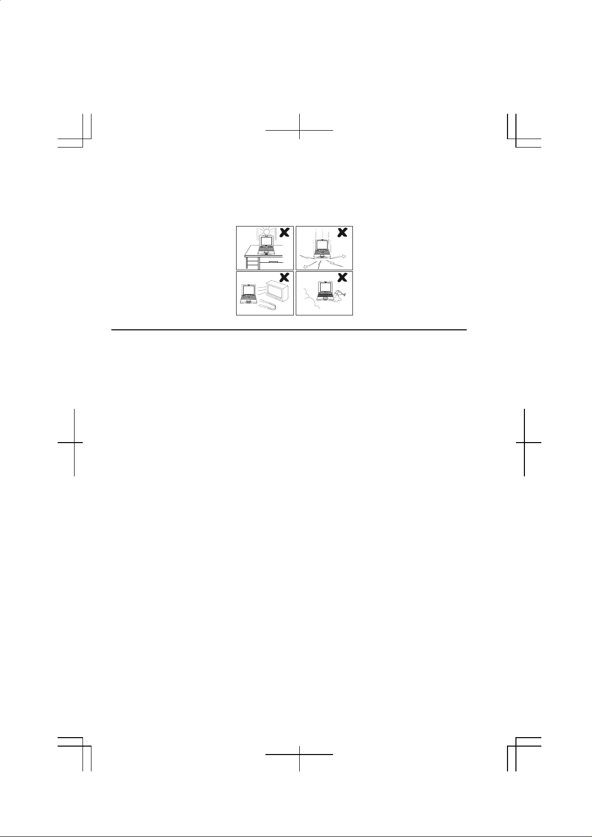
Location
•
Do not expose the computer to direct sunlight.
•
Try to avoid dusty environments.
•
Keep the computer away from any magnetic devices and TVs.
•
Keep the computer away from excessive humidity or fluids such as rain, snow,
water spray, juice, coffee, steam, etc.
•
Do not move the computer from an extremely cold place to an extremely warm
place. A temperature difference of more than 10°C (18°F) will cause
condensation inside the unit, which may cause damage.
•
Do not block or cover slots or openings on the cabinet. These protect the
computer from overheating.
•
Care should be exercised when using on heat sensitive surfaces or your lap as the
base of this computer will get hot.
Usage
•
Never push any objects of any kind into cabinet openings. They may touch
dangerous voltage points or short parts that could result in fire or electrical
shock.
•
Turn off the computer before installing or removing a peripheral device (except
when connecting USB devices and PC cards).
•
Check the AC power cord and power connectors periodically for damage.
Replace the power cord immediately if damage is found.
•
Never subject your computer to sudden shocks or extreme vibration.
ix
Page 10
•
Do not drop the computer nor hit it with other equipment.
•
Do not scratch the surface of the LCD screen.
•
Turn off the computer and disconnect the AC power cord before cleaning.
Battery Pack Precautions
CAUTION
DANGER OF EXPLOSION IF BATTERY I S INCORRECTLY REPLACED.
REPLACE ONLY WITH THE SAME OR EQUIVALENT TYPE
RECOMMANDED BY THE MANUFACTURER. DISCARD USED BATTERIES
ACCORDING TO THE MANUFACTURER'S INSTRUCTIONS.
Handling
•
Never put the battery pack in a fire, as it could explode and cause injury.
•
Do not attempt to open or alter the battery pack.
•
Do not place the battery where it might get hotter than 60°C (140°F).
•
Do not allow metal objects such as jewelry to short across the battery terminals,
as it could heat up and explode.
•
Do not allow liquids to come in contact with the battery pack.
•
Avoid dropping the pack or other violent shock.
•
Do not solder anything to the battery terminals.
Charging
•
Charge the battery pack only with the AC adapter included with your computer or
an optional one (may not available in some countries).
x
Page 11

Discharging
•
Do not use the battery pack for any purpose other than powering the computer.
Storage
•
Store the battery pack in a cool and dry place. Never allow the temperature to
exceed 60°C (140°F) during storage.
•
Recharge the battery pack after storage, before use.
Modem Precautions
•
Never install te lephone wiring during a lightning storm.
•
Never install telephone jacks in wet locations unless the jack is specifically
designed for wet locations.
•
Never touch uninsulated telephone wires or terminals unless the telephone line
has been disconnected at the network interface.
•
Use caution when installing or modifying telephone lines.
•
Avoid using the telephone during a lightni ng storm. There may be a remote risk
of electric shock from lightning.
•
Do not use the telephone to report a gas leak while in the vicinity of the leak.
(the built-in modem may not be available in some countries)
xi
Page 12

About This Manual
Notice
Information in this manual is subject to change without notice and does not represent a
commitment on the part of SHARP Corporation.
SHARP Corporation shall not be liable for technical or editorial errors or omissions
contained herein; nor for incidental or consequential damages resulting from the furnishing,
performance, or use of this material.
SHARP strongly recommends that separate permanent written records be kept of all
important data. Data may be lost or altered in virtually any electronic memory product under
certain circumstances. Therefore, SHARP assumes no responsibility for data lost or
otherwise rendered unusable whether as a result of improper use, repairs, defects, battery
replacement, use after the specified battery life has expired, or any other causes.
SHARP assumes no responsibility directly or indirectly, for financial losses or claims from
third persons resulting from the use of this product and any of its functions, such as stolen
credit card numbers, the loss of or alteration of stored data, etc.
Edition
1st Edition, August 2001.
Copyright
© 2001 SHARP Corporation
This document contains or refers to proprietary information whic h is protected by copyright. All rights
are reserved. Copying or other reproduction of this document is prohibited wi thout the prior wr itten
permission of SHARP Corporation.
Trademarks
Pentium is a registered trademark of Intel Corporation.
IBM is a trademark of International Business Machines Corporation.
Microsoft, MS-DOS, Windows, a nd the Windows Logo are regi stered trademarks of Microsoft
Corporation.
All other brand and product na mes are trademarks or registered trademarks of their respective holders.
xii
Page 13
Recording Important Information
For future reference, please record the following information in the spaces provided
below.
Model Number:
Serial Number:
Date of purchase:
Dealer’s Name:
Place of purchase:
Password:
The serial number is printed on a sticker located on the bottom of the computer.
xiii
Page 14
Manual Conventions
This manual uses a set of st yle c onventions descri bed below.
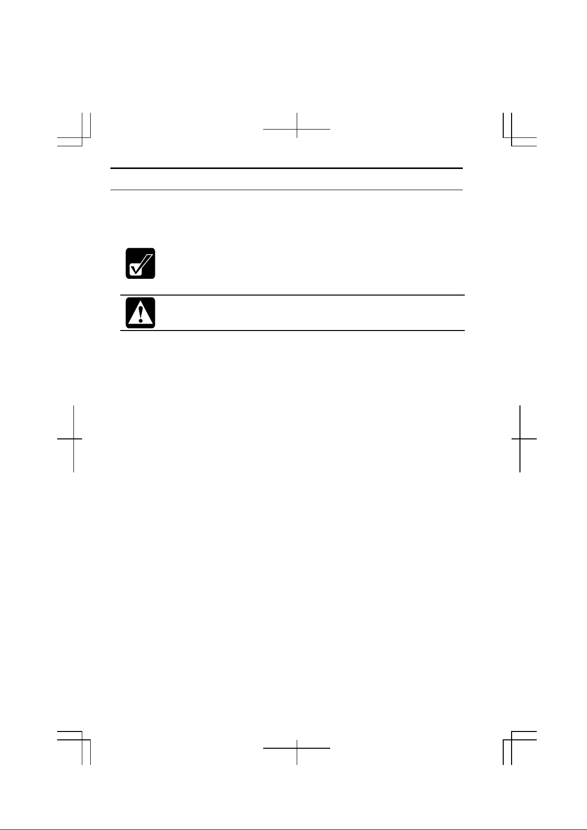
Notes and Cautions are italicized with icons:
A note icon informs you of a special technique or information that may
help you perform a task or better understand a process.
A caution icon alerts you to something that may cause problems or
damage to hardware, software or data.
Key Labels on the Keyboard, when referred to in the instructions, are shown in
boldface:
Press Enter to continue.
When two or more keys are pressed simultaneously, the key labels are separated by
a plus (+) sign:
Restart your computer by pressing Ctrl+Alt+Delete.
Sample Entries are shown in upper cases of different typeface.
C:/WINDOWS/SYSTEM
Words/Texts on Screen, such as window titles or possible parameters, are
italicized:
Double-click this icon to display the Power Properties window.
Set the item to Enabled.
Screens reproduced in this manual may differ slightly from the screens you see on
your computer.
Section Titles in other parts of this manual are italicized:
Refer to Installing Battery section in Chapter 1.
xiv
Page 15
Overview of Computer
Each number after an arrow indicates the page referring to the part. Actual
appearance of your computer may be slightly different depending on the model.
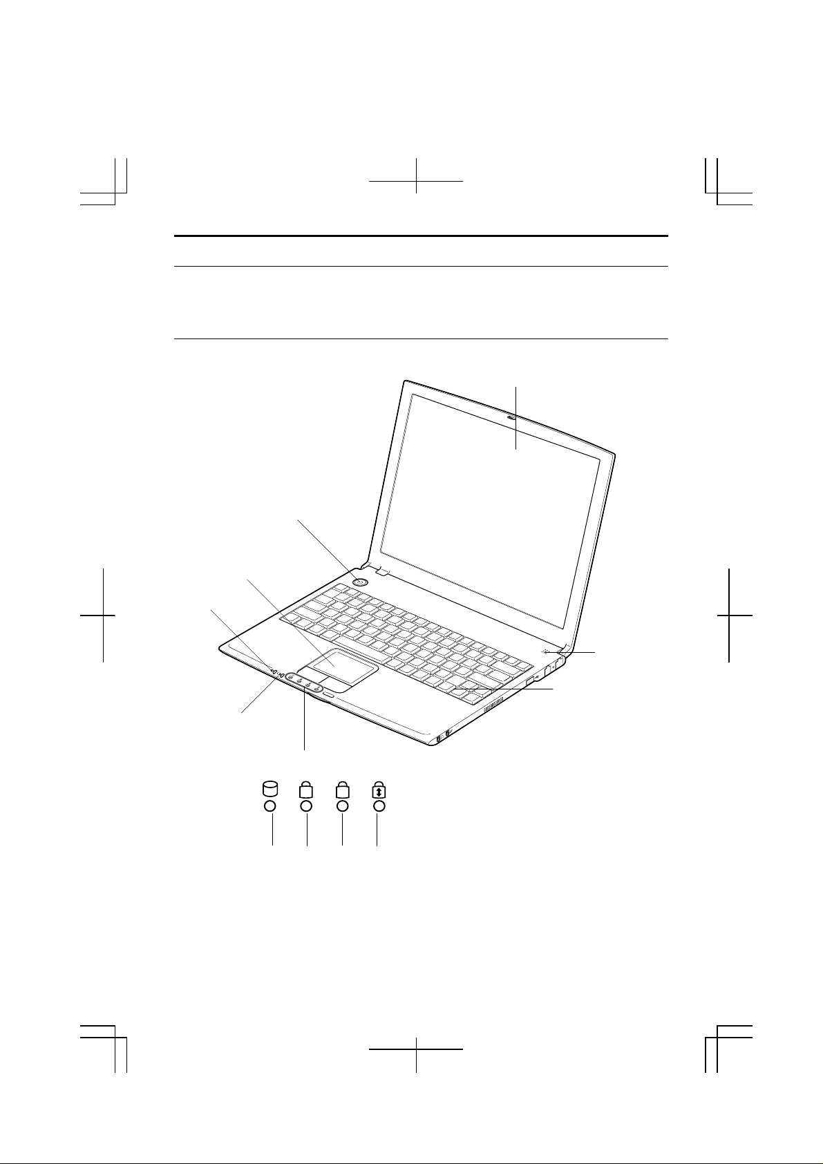
Front
Glide pad
→2-4
Power Indicator
→2-1
Battery Indicator
→2-1
LCD Screen
→4-11
Power Button
Microphone
Keyboard
→2-6
Status Indicator
Hard
Disk
Num
Lock
AN
Caps
Lock
Scroll
Lock
xvii
Page 16
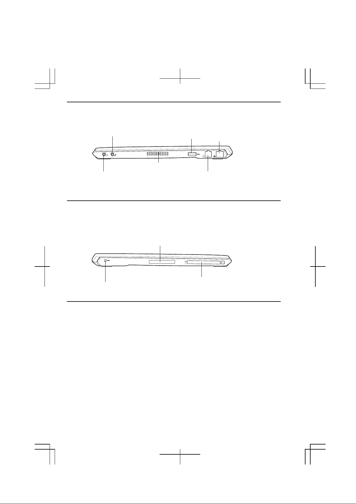
Right
Audio Output Jack
→4-14
Left
AC Adapter Jack
→1-3
Microphone Jack
→4-15
Ventilation Openings
→ix
USB Port
→4-3,4-6,4-16
Expansion Port
→4-11,4-20
PC Card Slot
→4-16
LAN Jack
→5-5
Modem Jack
→5-2
Bottom
xviii
Battery Pack
→3-1
Page 17
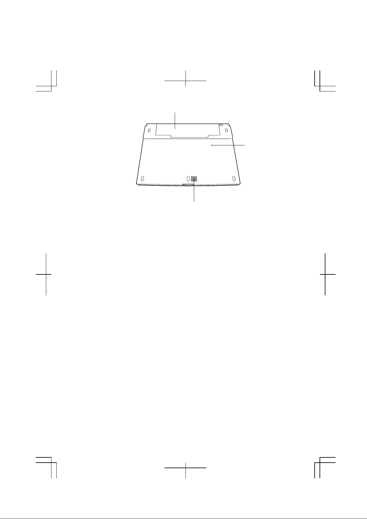
Speaker
Reset Switch
→2-3
xix
Page 18

Table of Contents
Notice for Users in USA............................................................................................ i
Notice for Users in Australia.................................................................................... iv
Notice for Users in the UK.........................................................................................v
Notice for Users in Europe....................................................................................... vi
Safety Precautions.................................................................................................... ix
About This Manual ................................................................................................. xii
Recording Important Information...........................................................................xiii
Manual Conventions...............................................................................................xiv
Table of Contents.....................................................................................................xv
Overview of Computer.......................................................................................... xvii
Quick Setup
Installing Battery Pack........................................................................................... 1-1
Connecting AC Power............................................................................................ 1-3
Setting Up Windows 2000 ..................................................................................... 1-5
Turning Off Your Computer .................................................................................. 1-6
Basic Operations
Choosing Power Source ......................................................................................... 2-1
Resetting the System.............................................................................................. 2-3
Using the Glide Pad ............................................................................................... 2-4
Using the Keyboard................................................................................................2-6
Using Windows 2000 Group Working System......................................................2-8
Battery and Power Management
Standard Battery Pack............................................................................................ 3-1
Optional High Capacity Battery Pack .................................................................... 3-7
Power Management ................................................................................................ 3-8
Peripherals
Using Peripherals................................................................................................... 4-1
Using Optional External Floppy Disk Drive Unit..................................................4-3
Using Optional External CD-ROM Drive Unit...................................................... 4-6
Display.................................................................................................................4-11
Audio System ....................................................................................................... 4-14
USB Device..........................................................................................................4-16
xv
Page 19

PC Card ................................................................................................................4-16
Printer...................................................................................................................4-19
Using Optional Port Bar .......................................................................................4-20
Communication Functions
Built-in Modem.......................................................................................................5-1
LAN unit................................................................................................................. 5-5
Setup Utility
Running the Setup Utility........................................................................................6-1
Main Menu..............................................................................................................6-3
Advanced Menu......................................................................................................6-4
Security Menu.........................................................................................................6-5
Exit Menu...............................................................................................................6-7
Appendixes
Converting File Format..........................................................................................A-1
Maintenance and Care ...........................................................................................A-2
Re-installation Instructions....................................................................................A-4
Troubleshooting
Index
xvi
Page 20
CHAPTER 1
Quick Setup
Your computer is designed and pre-configured for easy setup and use. This chapter
describes the st eps to get your computer up and running as quickly as possible.
Read this chapter first.
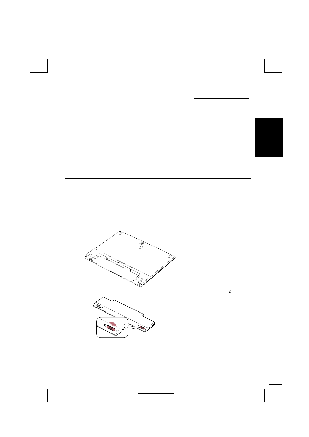
Installing Battery Pack
Your computer is powered with either the rechargeable battery pack or AC power.
See the next chapter for more information on power sources. Before using the
computer for the first time:
1. Place the computer upside down.
1
2. Slide the battery stopper on the battery pack to the unlocked position( ).
Battery Stopper
1-1
Page 21
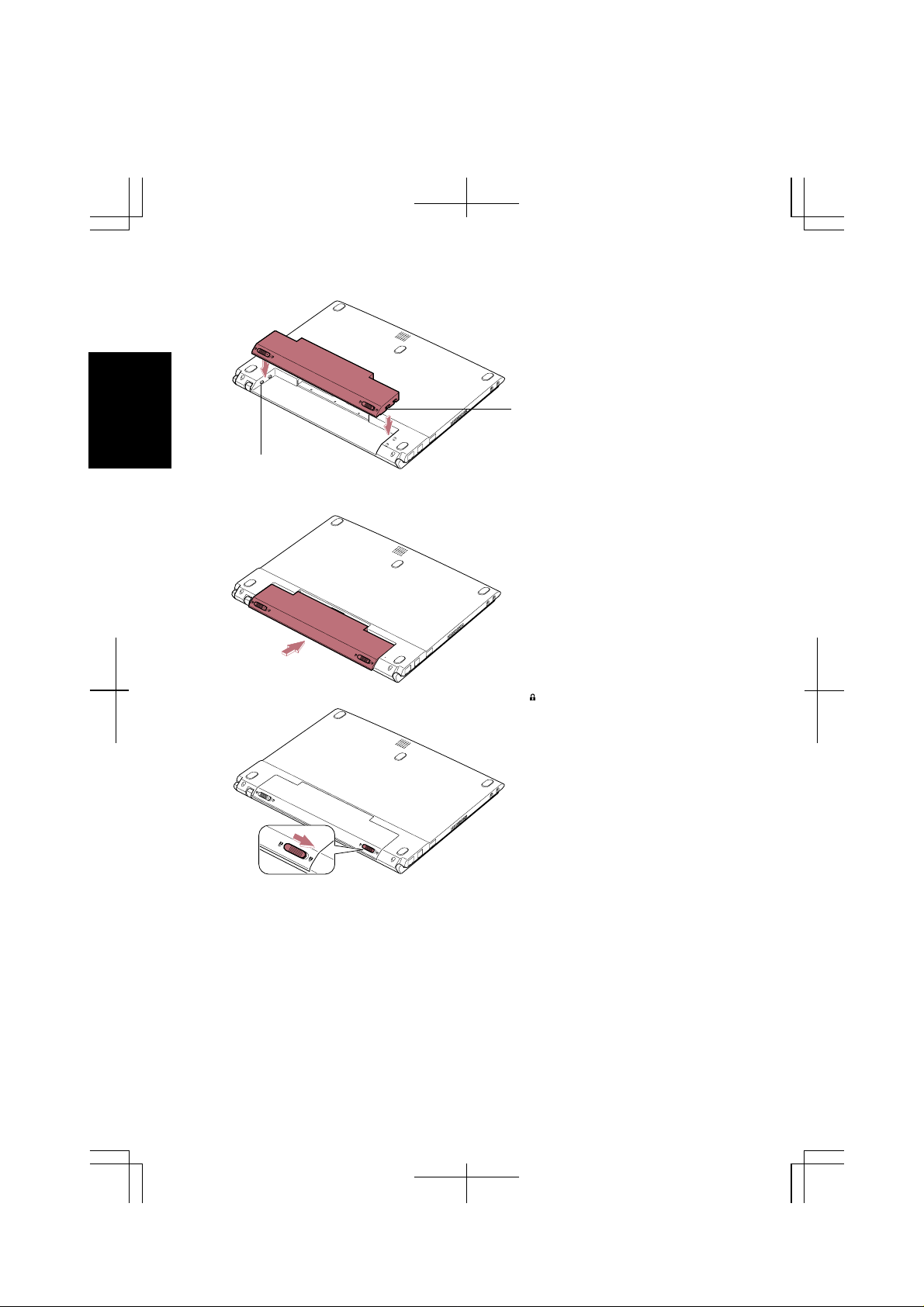
3. Insert the battery pack into the computer by matching the notched parts of the
battery to the projected parts on the computer.
1
Notched Part
Projected Part
4. Push the battery pack until you hear the clicking sound.
5. Slide the battery stopper to the locked position ( ).
6. Turn over your computer and go to the next section.
1-2
Page 22
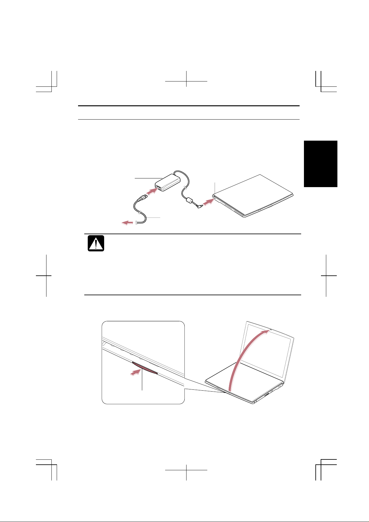
Connecting AC Power
1. Plug the AC adapter cable to the AC adapter jack on the left side of your
computer.
2. Plug the AC power cord into the AC adapter.
3. Plug the AC power cord into a wall outlet.
AC Adapter
AC Adapter Jack
1
To Wall Outlet
• Always use the AC adapter included with the computer or the optional
one (may not be available in some countries). Using other AC adapters
may damage the computer.
• Always hold the AC power cord by its plug when removing it from the
wall outlet. Never pull on the cord.
• When using the computer for the first time, be sure to connect it to AC
power. If using the battery instead, you may not be able to complete the
Windows 2000 setup if the battery does not have enough power.
4. Press the display cover lock button until the display cover releases, and raise
the cover.
Display Cover Lock Button
AC Power Cord
1-3
Page 23
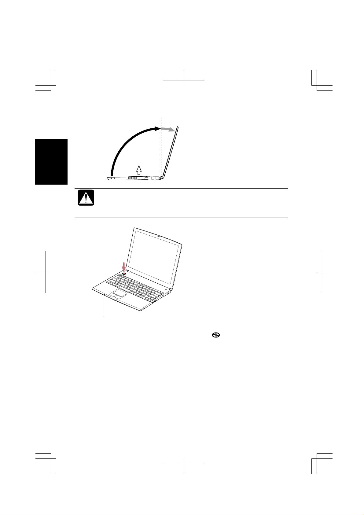
1
5. Tilt the cover to more than 90-degree.
90°
• The keyboard of your computer will raise automatically when you open
the display cover. You need to tilt the cover more than 90- degree to
raise the keyboard completely. Otherwise the keyboard or the computer
may malfunction.
6. Press the power button to turn on your computer.
Power Indicator
When you turn on the computer, the power indicator ( ) turns green, the
computer goes thr ough a self test to de t ect any problems, and
Professional Setup Wizard
1-4
starts. See the next page.
Windows 2000
Page 24
Setting Up Windows 2000
The steps in the setup process are as follows:
•
Accepting license agreement
•
Configuring the name of you and your organization
•
Configuring the setting of your computer within the wor k group
To set up Windows 2000, follow the instructions on the screen. See also the
Windows 2000 manual. It takes approximately 5-10 minutes to complete the entire
setup process.
• Do not turn off the computer until completing Windows 2000 setup. If
you turn it off, you cannot set up Windows 2000 later.
• Be sure to connect the computer to AC power. If using the battery
instead, you may not be able to complete the Windows 2000 setup if the
battery does not have enough power.
• Do not connect any peripheral devices to your computer unless
Windows 2000 setup completes. Otherwise your computer may
malfunction.
• If the display turns off, some power management may function. In this
case, press any key to resume your computer from the power
management.
• If you cannot operate the keyboard or the touch pad, press the power
button for more than four seconds to turn off the computer. Be sure that
the battery indicator turns off; then, after more than 10 seconds, press
the power button to turn it on again.
1
For Users Outside UK
After completing Windows 2000 setup, set your date and time. Double-click the
time appearing on the right of the task bar to open
Confirm
For UK Users
After completing Windows 2000 setup, double-click
U.K.users)
setting suitable for UK users. Then set date and time in
box.
Time zone
icon on the desktop and follow the instructions in it to customize the
is correctly selected, and set date and time.
Date/Time Properties
README FIRST (for
Date/Time Properties
dialog box.
dialog
1-5
Page 25
Properties Dialog Box in Windows
In the instructions in this manual, you will often see the expression “XXX
Properties dialog box.” A dialog box is a window containing text boxes, check
boxes, buttons, etc., with which you can send commands to Windows 2000 or other
application programs. To open the properties dialog boxes, click the
1
open the
XXX icon. Some of the dialog boxes you will use often are:
•
•
•
•
•
Start
menu; then, select
Display
Phone and Modem Options
Mouse
Power Options
System
Settings
Turning Off Your Computer
When you’re finished using your computer, turn it off with the following steps:
•
With a power button
Before using this step, confirm that
power button on my computer
dialog box.
•
From the Start menu
1. From the
2. In the
menu, and click OK.
Start
menu, select
Shut Down Windows
Advanced
in
Shut Down…
dialog box, select
Control Panel
-
Power Off
tab of
.
and double-click the
is selected in
Power Option Properties
Shut down
When I press the
from the pull-down
Start
button to
Close the cover to keep the screen and keyboard clean and protected.
If you have not saved a file, a dialog box will appear asking whether you
want to save it.
• Do not turn off or reset the computer while the hard disk indicator, or
the indicator on the optional external floppy disk drive unit, or optional
external CD-ROM drive unit are lit. Doing so may damage or even
wipe out the data.
• Before turning it back on, wait at least ten seconds after turning off the
computer. Turning the power off and on in rapid succession can
damage the computer’s electrical circuitry.
1-6
Page 26
CHAPTER 2
Basic Operations
This chapter describes the basic operations of your computer.
Choosing Power Source
You can use the computer with one of the following power sources:
•
AC power from a wall outlet
Use AC power whenever possible; rely on the battery only when AC power is not
available.
•
Rechargeable battery
Your computer is equipped with a standard battery. You can also use an optional
battery. See Chapter 3 for battery information.
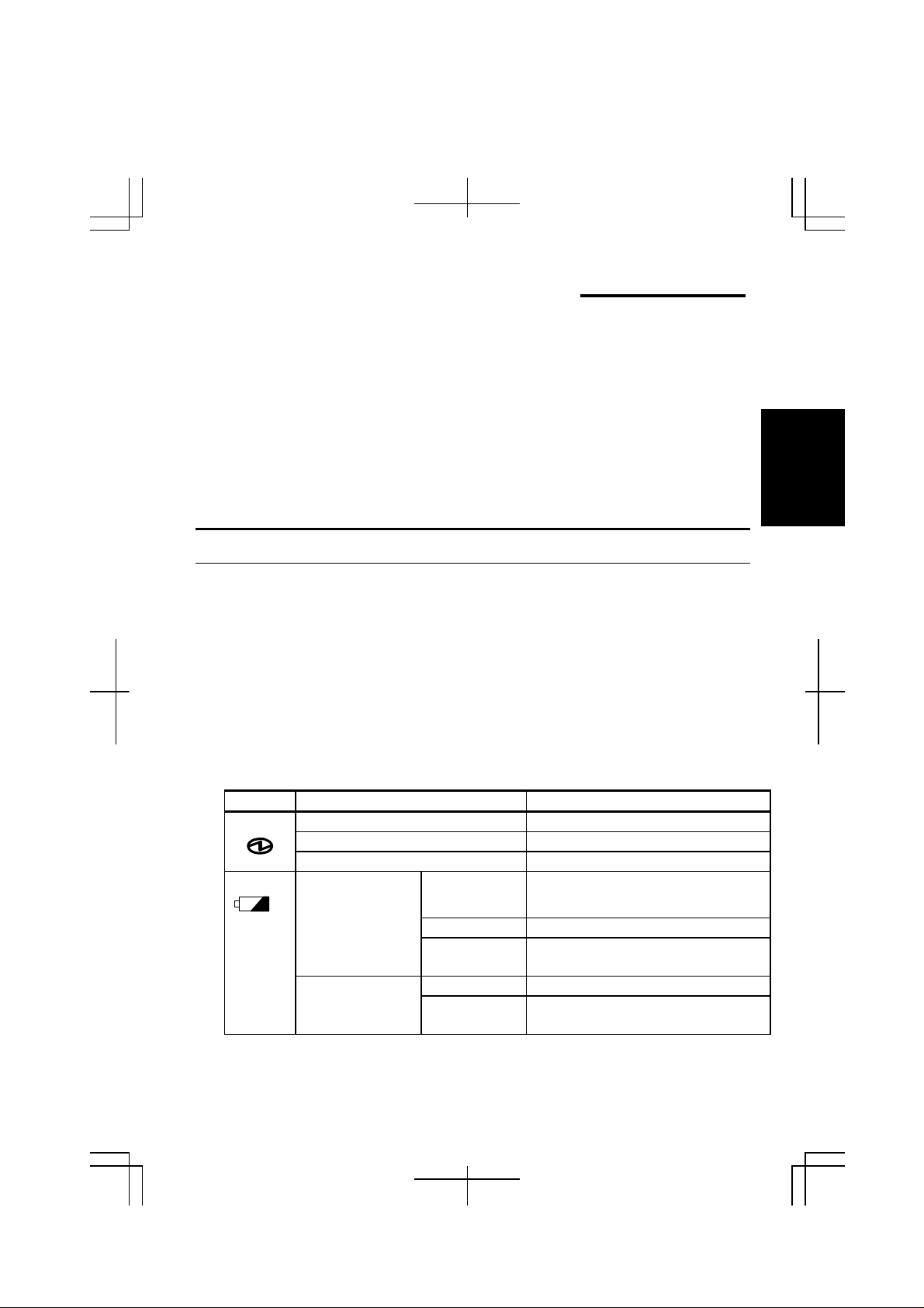
About the Power Indicators
The following indicators show the power status of your computer.
2
Indicator Light Meaning
Power On (green) Operating
Blinking (green) In System Standby
Off Powered off or in System Hibernate
Battery On (green) Fully charged
When Connected
to AC Power
Battery
On (orange) Being charged
Blinking
(orange)
Off Has powerWhen Run by
On (red) Almost completely discharged
In abnormal state
(The warning beep sounds)
2-1
Page 27
Battery indicator is always off when the computer is turned off and not connected to
AC power.
When the battery is hot, the battery indicator may turn off even if the
•
battery is being charged.
For more information on System standby/hibernate, see Chapter 3.
•
Using th e AC Ada pter
When connected to a wall outlet, the AC adapter provides power for operation and
2
charges the battery. The AC input voltage can range from 100 to 240 volts so that
you can use the computer with the appropriate plug adapter.
The AC power cord included with the computer is appropriate for the
voltage used in the area in which you purchased your computer. If you
attempt to connect the computer to a wall outlet other than in this area,
check the voltage of the outlet and use an AC power cord appropriate for
the outlet. Consult local service staff if you a re unsure.
2-2
Page 28
Resetting the System
You may need to reset the system after adding hardware or software so that your
computer will recognize the newly installed devices or software. When the message
appears after the installation, click OK,
You can also restart Windows 2000 from the
Restart.
Resetting may cause data loss. Use the resetting process only if the
normal Windows 2000 Shut Down does not work because of software
malfunction. Although resetting will not damage the system, you may
lose the data you are processing.
Power Sw itch
You can turn off the computer with the power button if you encounter hardware or
software problems which lock up the system. In this case, press the power button for
more than four seconds.
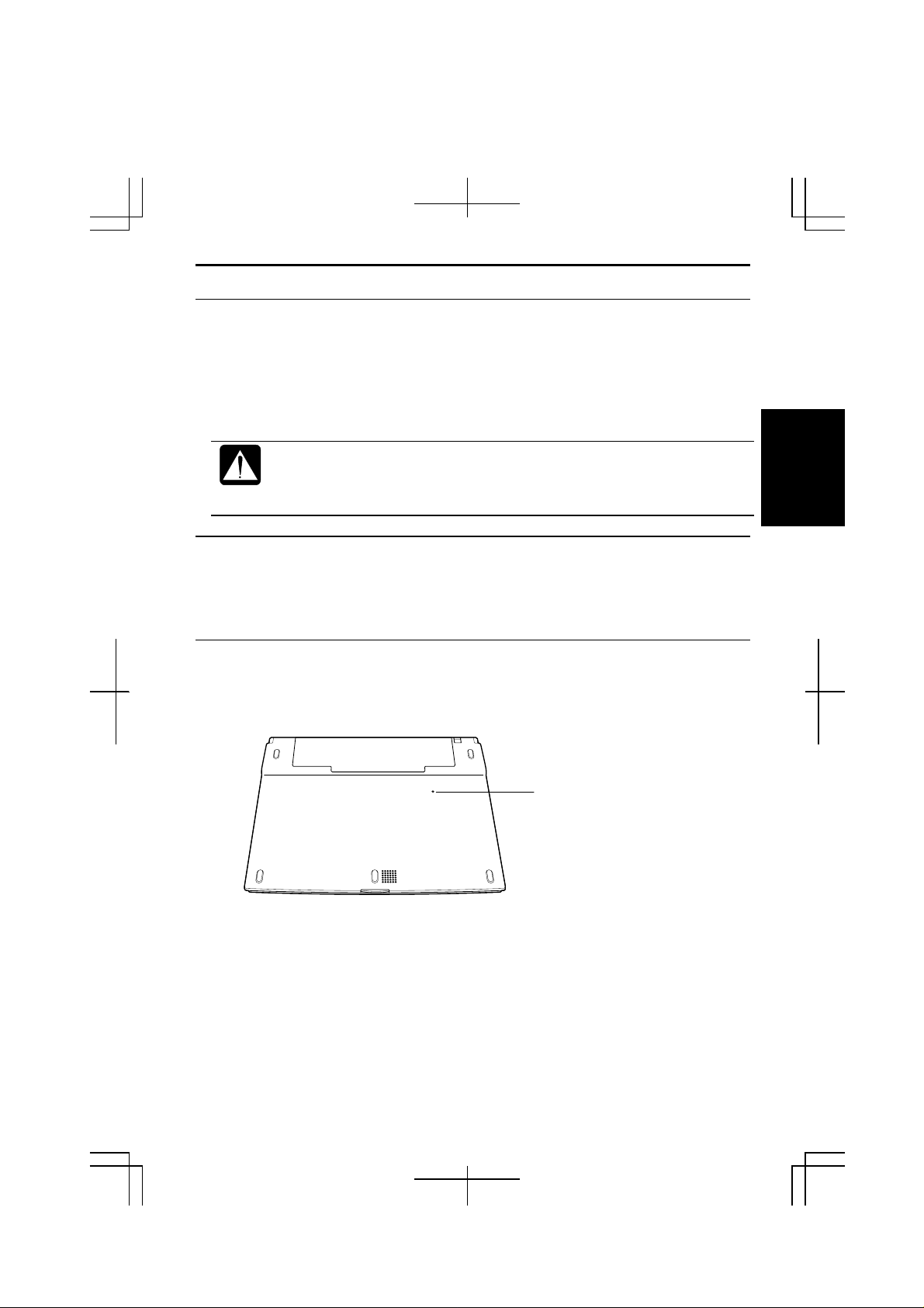
Reset Switch
If you cannot turn off the computer by pressing the power button, you can use the
reset switch on the bottom of your computer. To reset the system, insert a narrow
object into the small hole to press the switch.
Yes
, etc. to restart Windows 2000.
Start
menu. Select
Shut down
; then,
2
Reset Switch
2-3
Page 29
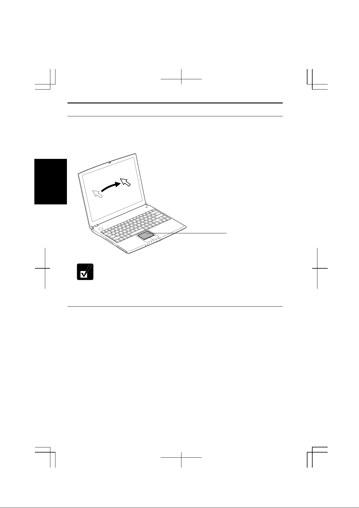
Using The Glide Pad
Your computer is equipped with an integrated pointing device called a glide pad.
Using the glide pad, you can move the pointer, select an item from a menu, and
perform other tasks in the same way you would with a mouse.
2
Do not hit or scratch the surface of the glide pad with pointed objects
•
(such as a ballpoint pen).
Do not operate the glide pad with a moist finger. This may cause the
•
glide pad to operate incorrectly.
Glide Pad
Using the Glide Pad
Take a moment to become familiar with how the glide pad works.
Place Your Fingertip
Place your left or right hand next to the glide pad, resting your wrist naturally in a
relaxed manner. Place your thumb or finger on the glide pad.
Move Your Fingertip
The rectangul ar pad of the gli de pad acts like a miniature dupli cate of the disp l ay.
As you slide your fingertip across the pad, the pointer on the screen moves in the
same direction across the screen. The glide pad is very sensitive, so you do not have
2-4
Page 30

to exert much pressure on the pad. The glide pad will respond to a light touch from
your fingertip.
Click, Double-click, and Right-click
To click or double-click, you can use the left button just like that of a mouse.
Instead of clicking the left button, you can also just tap gently anywhere on the
rectangular pad. For right -clicking, you must use the right button.
Drag and Drop
You can move icons or windows by using “drag and drop” below:
1. Position the pointer over the object.
2. Press the left button; do not release it.
3. Holding down the button, move the pointer. The object moves together with
the pointer.
4. Release the button when the object reaches its destination.
Or you can tap the pad twice instead of pressing the left button in step 2.
Scroll
You can scrol l through informatio n in a list or in a document by using the glide pad.
To view information vertically, place your finger on the most right part of the glide
pad and slide your finger up and down. To view horizontally, place your finger on
the bottom part of the glide pad and slide your finger left or right. This procedure
works only in limited applications.
2
Changing the Configuration
Mouse Properties
In the
pad, such as swapping left and right buttons, changing the pointer size, etc. Doubleclick
icon on the task bar.
dialog box, you can change the configuration of the glide
2-5
Page 31

Using The Keyboard
Your computer, equipped with the Windows Enhanced Keyboard, provides all the
functionality of a full-sized desktop keyboard. The keyboard will raise
automatically when you open the display cover.
The keyboard of your computer will raise automatically when you open
•
the display cover. You need to tilt the cover more than 90- degree to
raise the keyboard completely. Otherwise the keyboard or the computer
2
Special Keys
may malfunction.
90
°
Opens the Windows Start menu.
Windows Key
Opens an application-specific short-cut menu
Application Key
System Function Keys
When pressed together with the Fn key, function keys set speci fic system
parameters. This combination is sometimes referred to as “hot keys”.
Fn + F3
Fn + F4
Fn + F5
Fn + F6
2-6
Decreases the audio volume
Increases the audio volume
Rotates display mode in LCD only, CRT only, and
simultaneously display.
Decreases the LCD screen brightness.
equivalent to right-clicking.
Page 32

Fn + F7
Increases the LCD screen brightness.
Fn + F11
Fn + F12
Turns on and off the LCD screen.
Forces the computer into System standby/System
hibernate/shutdown. See
more information.
Power Management
of Chapter 3 for
2
2-7
Page 33

Using Windows 2000 Group Working System
For the details, refer to Windows 2000 Professional Quick Start Guide.
Registering New Users to Your Computer
1. Log on to your computer with the name of the administrator.
2. From the
3. Double-click
2
4. In
5. Type a new user’s name and click
6. Type a new user’s password twice; then, click
7. Select the user’s access level and click
8. Click OK to close the dialog box.
9. Close
Users and Passwords
password to use this computer
Control Panel
Changing User Name
1. Follow the steps 1 to 3 of the above.
2. In
3. Change the name and cli ck
4. Click
5. Type the user name and its password; then, click OK to log on to the system.
6. Close
Users and Passwords
password to use this computer
change its name.
Yes
Control Panel
Start
menu, select
Users and Passwords
window.
.
window.
Settings – Control Panel
icon.
dialog box, check
; then, click
Next
dialog box, check
; then, double-click the user name you want to
OK
twice.
Users must enter a user name and
Add…..
.
Finish
Users must enter a user name and
Next
.
.
.
Changing User Password
If you want to change the pa sswor d of the currentl y lo gged-on user;
Ctrl
Alt
1. Press
2. In
3. Type the old and new passwords; then, the new password again for
2-8
Windows Security
confirmation.
+
Delete
+
window, click
simultaneously.
Change Password….
Page 34

4. Click OK twice.
5. Click
If you want to change the password of another user (For administrator only);
1. Follow the steps 1 to 3 of the above.
2. In
3. Click
4. Type the new password twice for confirmation.
5. Click
Cancel
to back to Windows 2000.
Users and Passwords
password to use this computer
its password.
Set Password…..
OK
twice.
dialog box, check
Users must enter a user name and
; then, click the user name you want to change
2
2-9
Page 35

2
2-10
Page 36

CHAPTER 3
Battery and Power Management
This chapter explains how to manage the computer’s power effectively and use the
standard battery pack or an optional battery pack.
In this section, you often see the expression “
dialog box”. To open the dialog box:
1. From the
Double-click
2.
menu, select
Start
Power Options
Settings – Control Panel.
Power Options Properties
icon.
Standard Battery Pack
When not connected to an external power source, your computer operates with the
rechargeable standard battery pack. The duration of the battery life may be longer if
the computer’s Power Management is active. See the next section for power
management.
To keep the battery life long:
•
Initialize the battery pack if the actual remaining power in your battery is less
than what Windows Power Meter indicates.
•
Turn off your computer when you are not usi ng it.
The duration of the battery will depe nd on the computer usage.
•
Applications which heavily use the peripherals will experience shorter
power duration.
When the battery has not been charged, your computer may not
•
operate properly. Connect the AC power to charge the battery.
When using the computer for several hours with battery packs, enable
•
power management and set
Management
section in this chapter.
System Hibernate
. Refer to the
Power
3
3-1
Page 37

Charging the Battery Pack
1. Connect the AC adapter to the computer. While the battery is being charged,
the battery indicator turns orange.
2. When the battery is fully charged, the battery indicator turns green. Charging
time may vary according to the status of the computer.
Battery indicator may turns off even while the battery pack is being
•
charged. This is because the battery pack is hot, and the charging
stops temporarily. When the battery becomes cool, the charging will
start and the battery indicator turn on again.
The battery pack may not be installed correctly if the battery indicator
•
blinks orange. In this case, turn off the computer, remove the AC
3
adapter and the battery pack; then, install the battery pack and
connect the AC adapter again. If the battery indicator still blinks
orange, ask your local dealer for assistance.
When the battery pack is hot(for example, after a long usage), it may
•
take longer to fully charge the battery pack.
Checking the Battery Level
You can check the battery level by pointing to the battery or AC plug icon on the
taskbar, or double-clicking the icon to open the
If you cannot see the battery or AC plug icon, follow the instructions below:
1. In the
2. Check
3. Close
Power Options Properties
Always show icon on the task bar
Control Panel
window.
Power Meter
dialog box, select
and click OK.
dialog box.
Advanced
tab.
3-2
The remaining operating time depends on the power you are
•
consuming. If you are using the audio system, PC card slot, hard disk
drive, floppy disk or CD-ROM, your computer may consume more
battery life.
If the actual remaining power in your battery is less than what
•
Windows Power Meter indicates, you should initialize the battery pack
as per the procedure on “
Intializing Battery Pack”.
Page 38

Low Battery Indication
When the battery power becomes significantly low, the battery indicator
red, the warning beep sounds for a bout ten second s. Save your data and turn off the
computer, or connect the computer to AC power immediately. Otherwise, the
computer will be shut down and the data may be lost.
Battery Indicator
In Windows 2000, the alarm will tell you when the battery drops to the specified
level by sounding an al arm or displaying a message, and let your comput er go on
System standby/ hibernate
or be shut down automatically.
(
)
turns
3
1. In the
2. Set the battery level at which the alarms are activated. We recommend you set
3. Set the
4. Click OK twice.
5. Close the
Power Options
Critical battery alarm
Alarm Action
Control Panel
dialog box, select
to more than 5 %.
desired.
window.
Alarms
tab.
Initializing the Battery Pack
You need to initialize the battery pack when the actual remaining power in your
battery is less than what Windows Power Meter indicates, or you buy a new battery
pack.
3-3
Page 39

1. Make sure the computer is turned off. Connect the computer to AC power and
wait until the battery is fully charged. The battery indicator turns orange first;
then, turns to green when the battery pack is fully charged.
2. Turn on the computer.
3. When the message
Utility.
4. Disconnect the AC adapter, and leave the computer on until the battery is
completely discharged and the system shuts down automatically.
5. Connect the computer to AC power and let the battery fully charge again.
6. Turn on the computer and follow the steps 3 to 5 again.
7. Restart the computer. The initializing process is complete.
3
Do not connect the computer to wall outlet while discharging the battery.
The initialization will be cancelled.
Changing the Battery Pack
The capacity of a battery pack gradually decreases when used repeatedly (the
deterioration rate depends on the operating environment). If the battery life
becomes extremely short even after the initialization, you should buy a new standard
battery pack (CE-BL17). An optional battery pack (CE-BL18) is also available in
some countries.
<F2> to enter SETUP
appears, press F2 to open the Setup
When you replace the battery pack with a new one:
1. Turn off the computer and disconnect the AC adapter from the computer.
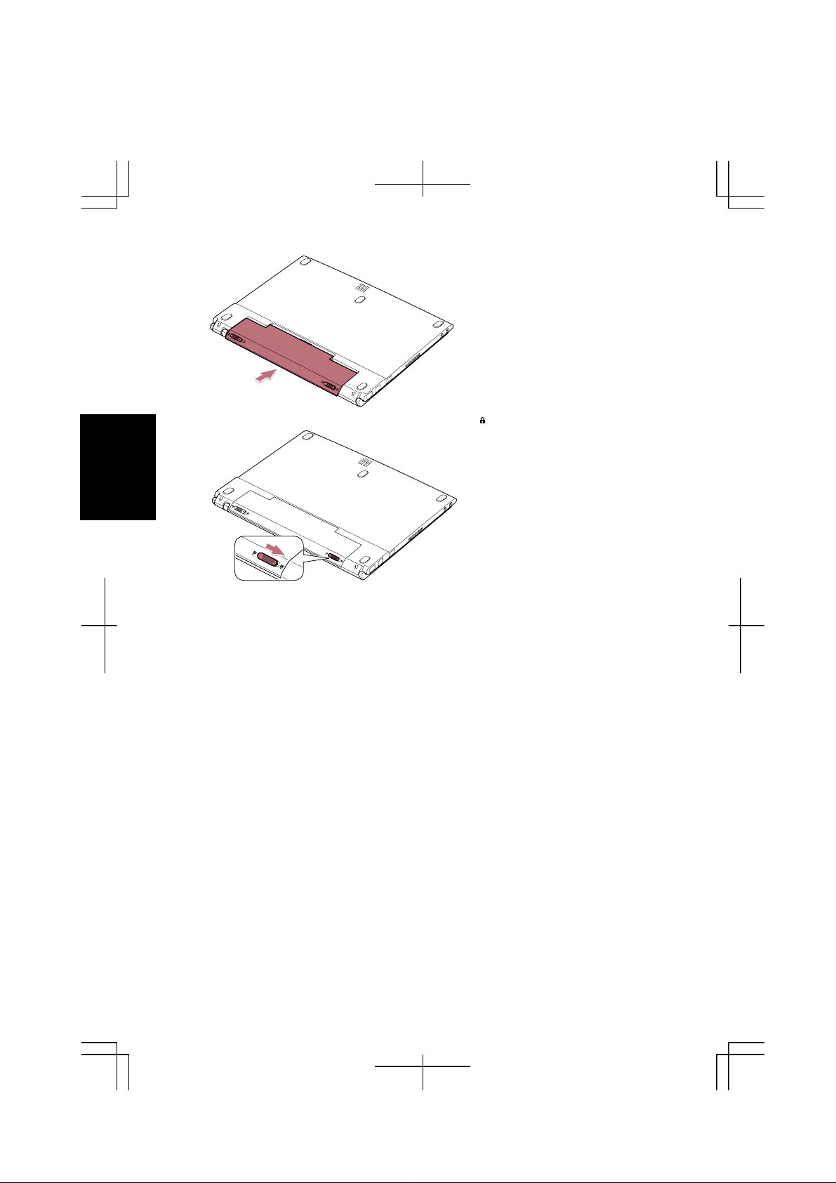
2. Close the display cover and turn over the computer on a flat place.
3. Slide the battery stopper to the unlocked position (
Battery Stopper
).
3-4
Page 40

4. Slide the battery release lever to right and hold it; then, pull out the battery
pack.
Battery Release Lever
5. Lift up the battery pack and remove it from the computer.
6. Slide the battery stopper of a new battery pack to the unlocked position ( ).
3
7. Insert the battery pack into the computer by matching the notched part of the
battery to the projected parts on the computer.
3-5
Page 41
3
8. Push the battery pack until you hear the clicking sound.
9. Slide the battery stopper to the locked position ( ).
10. Turn over the computer and it’s ready to use.
3-6
Page 42

Optional High Capacity Battery Pack
To power your computer for extended periods of time, there is an optional battery
pack, the high capacity battery pack (CE-BL18)(may not be available in some
countries).
Battery Release Lever
Use only the appropriate optional battery (CE-BL18), and attach it
correctly.
Battery Stopper
Connecting High Capacity Battery Pack
Follow the steps in
Changing the battery pack
of this chapter.
Charging High Capacity Battery Pack
Follow the steps in
Charging the battery pack
of this chapter.
Checking the Battery Level of High Capacity Battery Pack
Follow the steps in
Checking the Battery Level
of this chapter.
Initializing the High Capacity Battery Pack
Follow the steps in
Initializing the battery pack
of this chapter.
3
3-7
Page 43

Power Management
Power management saves electricity and extends battery life by controlling power
supply to built-in devices. You can set the following power management properties
in Windows 2000.
•
Stopping power supply to the hard disk
•
Stopping power supply to the display
•
Controlling CPU speed
•
Using System stand by/hibernate
3
To open
–
Power Options Properties
Control Panel
, and double-click
Note that the power management may not seem to function under the
following conditions:
When you are using an application program that accesses the hard disk
•
periodically
When Windows CD Auto Play is functioning
•
dialog box, from the
Power Options
Stopping Power Supply to the Hard Disk
1. In the
2. Set
3. Close
Power Options Properties
Turn off hard disks
Control Panel
to an appropriate value, and click OK.
window.
dialog box, select
Stopping Power Supply to the Display
This procedure is also effective for an attached external monitor complying
with power management.
1. In the
2. Set
3. Close
Power Options Properties
Turn off monitor
Control Panel
to an appropriate value, and click OK.
window.
dialog box, select
Start
icon.
Power Schemes
Power Schemes
menu, select
tab.
tab.
Settings
3-8
Page 44

Controlling CPU Speed
Your computer is equipped with Intel® SpeedStep™ technology which can control
CPU speed to reduce power consumption.
Do not control CPU speed while communicating, or reading/writing
data. Otherwise the computer may malfunction.
1. Double-click
2. In
3. Click OK.
Intel(R) SpeedStep(TM) technology
performance.
If
•
checked in the dialog box, CPU speed will change automatically when
the AC adapter is connected/disconnected except while using the builtin modem.
You can also select the performance by right-clicking the icon, or
•
selecting
Properties
or icon on the task bar.
dialog box, select the CPU speed
Automatically change performance when the power source changes
Intel(R) SpeedStep(TM) technology
dialog box.
tab in
Power Options
Using System Standby/Hibernate
System standby/hibernate
after your computer has entered
computer more quickly when compared to a restart, after a normal shutdown
operation. When your compute r resumes from
restores the exact last state of the computer. In Windows 2000, you can define
System standby or System hibernate
•
System standby
power supply to all but a few essential components. Your system enters and
resumes from
standby
operate the computer again.
System standby
, the Power indicator blinks green. To resume from
is a very useful power management to ol. For example,
System standby
the system enters under what conditions.
stores the current condition of the computer in RAM and stops
per the conditions mentioned later. In
mode, you can restart your
System standby/hibernate
System standby
, the system
System
,
is
3
•
System hibernate
hard disk and turns off the computer. Your system enters and resumes from
System hibernate
power indicator turns off. To resume from
button.
saves the current condition of the computer in an area of the
per the conditions mentioned later. In
System Hibernate
System hibernate
, press the power
, the
3-9
Page 45

When entering/resuming from
instructions below:
Finish communications, printing, and playing music or video before
•
entering
Do not operate the computer or peripheral devices, or
•
connect/disconnect peripheral devices while entering/resuming from
System standby/hibernate
While operating with a battery, the computer may not resume from
•
System standby/hibernate
this case, connect the AC adapter to your computer.
Save your data before your computer enters
•
power supply to the computer is stopped, the RAM contents will be lost.
System standby/hibernate
System standby/hibernate
.
if the battery capacity left is not enough. In
System standby
, follow the
. If the
3
Supporting System Hibernate
If your battery becomes completely discharged during
you will lose unsaved data and will need to reboot your computer.
Therefore, if you are planning to leave your computer powered by battery
for long periods of time, we recommend
Let your computer support
1. In the
2. Check
3. Click OK.
4. Close
Set Timer to Enter System standby/Hibernate Automatically
Your computer will enter System standby/hibernate automatically when the
specified time has passed without any operation. To set the time:
1. In the
2. Set the time after which the computer will enter System standby/hibernate in
3. Click
4. Close
Power Options Properties
Enable hibernate support
Control Panel
Power Options Properties
System standby
OK.
Control P
System hibernate
window.
System hibernates
or
anel window.
dialog box, select
.
dialog box, select
.
System hibernate
by following the steps below.
Hibernate
Power Schemes
System standby
.
tab.
tab.
,
3-10
Page 46

Entering System Standby/hibernate
Your computer enters
•
You select
•
The specified time in
Power Options Properties
of
the previous section).
•
The screen cover is closed
The above functions if you perform the following:
1. In
2. Select
3. Click OK.
4. Close
•
You press the power button.
The above functions if you perform the following:
1. In the
2. Select
computer
3. Click OK.
4. Close
Stand by or Hibernate
the Power Options Properties
Hibernate
Control Panel
Power Options Properties
Hibernate
:
Control Panel
System standby/hibernate
Shut Down Windows
in the
System standby or System hibernate
dialog box has passed without any operation (See
.
dialog box, select Advanced tab.
or
or
Standby
Standby
window.
window.
When I close the lid of my portable computer
in
dialog box, select
When I press the power button on my
in
in each of the following cases:
dialog box.
Power Schemes
in
Advanced
tab.
tab
3
:
•
You press Fn +
The above functions if you perform the following:
1. In the
2. Select
3. Click
4. Close
•
The battery level is low.
The above functions if you set the alarm in Windows 2000. See
Indication
Power Options Properties
Hibernate
OK.
Control Panel
in this section.
F12
.
or
Standby
window.
dialog box, select
When I press the sleep button on my computer:
in
Advanced
tab.
Low Battery
3-11
Page 47

Disabling Power Management
3
1. In the
2. Set
3. Close
Turn off monitor, Turn off hard disks, System standby
hibernate
Power Options Properties
Never
to
Control Panel
, and click OK.
window.
dialog box, select
Power Schemes
System
, and
tab.
3-12
Page 48

CHAPTER 4
Peripherals
This chapter describes how to use peripheral devices with your computer. You can
connect a floppy disk drive unit, a CD-ROM drive unit, a printer, external monitor,
or other devices to your computer. To ensure proper use, be sure to read the
instructions for each peripheral device before connecting it to your computer.
Using Peripherals
You can use the peripheral devices shown on the next page. For the details, refer to
the section explaining each device, and contact your dealer.
•
Be sure to turn off the computer and the peripheral device before
connecting them (except when connecting USB devices or inserting a
PC card).
•
Confirm the peripheral device you will connect is Windows 2000
compatible.
•
Some devices have to be turned on after the computer is turned on.
•
Some devices require that you install drivers before use (You may need
to connect an optional external floppy disk drive unit or an optional
external CD-ROM unit to install the drivers.)
4
4-1
Page 49

Peripheral Connection Overview
4
USB Device*
Microphone
Port Bar/Display
Audio Equipment
*Including the optional external floppy disk drive unit (CE-FD04) and the optional
external CD-ROM drive unit (CE-CD05).
PC Card
4-2
Page 50

Using Optional External Floppy Disk Driv e Unit
You can use double-density (2DD) 720KB or high-density (2HD) 1.44MB floppy
disks with the optional external floppy disk drive unit (CE-FD04).
Connecting Optional External Fl oppy Disk Drive Unit
•
Do not place the floppy disk drive unit on its side or upside down.
•
Do not press on the floppy disk drive unit. It may damage the drive or
cause malfunction.
•
Do not place the AC adapter on the floppy disk drive unit. It may cause
the drive to malfunction.
1. Connect the floppy disk drive unit cable into the unit.
2. Connect the core side connector of the floppy disk drive unit cable to the USB
port on the computer. Be sure to let the USB mark side up when connecting
the cable to the computer.
4
USB Mark
Core
Handling Floppy Disks
•
Do not open the shutter and touch the disk inside; otherwise, you will not be able
to read or write data to the disk.
•
Do not place floppy disks near magnets or heat source, in direct sunlight or in a
dusty place, etc.
4-3
Page 51
•
g Up
Never subject a disk to sudden shocks or extreme vibration. Do not drop, bend,
or place heavy objects on a disk.
•
Do not spill liquid onto a disk.
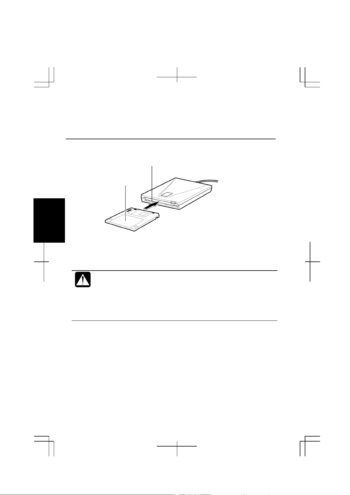
Inserting and Removing a Floppy Disk
Indicator
Label Facin
4
Inserting
Hold the floppy disk with the arrow facing up and towards the drive. Slide the disk
into the drive until it locks into place.
•
Always insert a floppy disk straight into the floppy disk drive.
•
When inserting the disk, make sure it is not upside down.
•
Do not use excessive force when inserting the floppy disk. If you have
difficulty inserting or removing disks, seek the assistance of an
authorized service technician.
•
Do not touch the disk while reading/writing data. It may cause
malfunction of the computer and the drive.
4-4
Page 52

Removing
Before removing the floppy disk, make sure the indicator of the floppy
disk drive unit is not lit.
Press the eject button firmly. The disk will pop out slightly. Remove it and store it
properly.
Formatting a Floppy Disk
1. Make sure the floppy disk is not write-protected, and insert it into the floppy
disk drive.
2. Double-click
3. Right-click
menu.
4. From the capacity drop-down list, select 1.44MB.
5. Click
Start
When you format a floppy disk, all data previously stored on the disk is
lost.
My Computer
3 ½ Floppy [A:]
to start formatting.
on the desktop.
icon; then, click
Format
from the pull-down
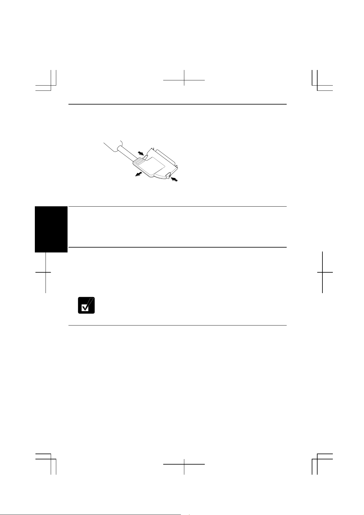
Removing Optional External Floppy Disk Drive Unit
To remove the unit, you need to perform the following before you remove it:
1. Click
2. Click
3. Click
Unplug or Eject Hardware
Stop Mitsumi USB Floppy – Drive(A:)
OK in Safe To Remove Hardware
icon (
) on the task bar.
; then remove the unit.
.
4
4-5
Page 53

Using Optional External CD-ROM Drive Unit
Compact disc (CD) is a storage medium, with which you can read data, play music,
install and run programs, etc. The optional external CD-ROM drive unit (CECD05) can be connected to the USB port on the right side of the computer.
CAUTION FOR LASER
Use of controls or adjustments or performance of procedures other
than those specified herein may result in hazardous radiation exposure.
Maximum output and wavelength of the laser: 903μW, 785nm
CLASS1LASERPRODUCT
4
Precautions
•
•
Do not disassemble the CD-ROM drive unit and do not repair by yourself,
otherwise it may cause electrical shock hazard, or a laser may damage your eyes.
Do not store or use the CD-ROM drive unit in a dusty, humid, oily environment,
or under damp or moist conditions.
LASERKLASSE1
•
Do not turn up t he volume too high, when using the headphones.
•
Do not leave the CD-ROM drive unit in direct sunlight, near a heat source or
especially in a hot automobile.
•
Do not drop or jar the CD-ROM drive unit.
•
Do not touch the pins/terminals of the USB cable.
•
When the CD-ROM drive unit has been moved from a cold place to warm place,
it may damp or moist. Leave it for about 1 hour before using.
•
Keep magnetic objects away from the CD-ROM drive unit.
•
Do not insert any foreign metal object inside the CD-ROM drive unit.
•
Do not touch the lens.
4-6
Page 54

•
If noise is heard from radio or TV, move the CD-ROM drive unit 2 m (about 6
ft.) away from the radio or TV.
Connecting Optional External CD-ROM Drive Unit (CE-CD05)
•
Do not place the CD-ROM drive unit on its side or upside down.
•
Do not press on the CD-ROM drive unit. It may damage the drive or
cause malfunction.
•
Do not place the AC adapter on the CD-ROM drive unit. It may cause
the drive to malfunction.
1. Connect the core side connector of the included USB cable to the cable
connector of the drive unit.
USB Cable
Cable
Connector
2. Connect the USB connector of the cable into the USB port of the computer.
4
USB Port
Power Indicator
The CD-ROM drive unit turns on automatically and the power indicator is
lit.
4-7
Page 55

3. Slide the cover latch to the right and open the cover.
Cover Latch
4. Remove the protection sheet before you use the drive first time.
Protection Sheet
4
Handling CDs
•
Do not write on either side of the disk, particularly the non-label side. Data is
read from the non-label side. Do not mark this surface.
•
Keep your disks away from direct sunlight, heat and excessive moisture.
•
Always hold the CDs by the edges. Fingerprints, dirt or water on the CDs can
cause noise or mistracking. If a CD is dirty or does not play properly, clean it
with a soft, dry cloth, wiping straight out from the center, along the radius.
Laser Beam
Inserting a CD
You can operate the optional external CD-ROM drive unit only when the computer
is on.
1. Make sure the busy indicator does not light on.
Busy Indicator
2. Slide the cover latch to the right to open the cover and raise it.
4-8
Page 56

3. Place your CD onto the disk spindle and press on the center of your CD with
x
˚
L
A
B
E
L
label side up, until it locks onto the disk spindle.
4. Close the disk cover.
•
Insert a CD firmly until it locks onto the spindle; then, close the disk
cover, or the disk may fall off the spindle and get damaged.
•
Do not leave the tray open. Also, avoid touching the lens in the tray. If
the lens becomes dirty, the CD-ROM may malfunction.
•
Do not wipe the lens with materials with rough surface (such as paper
towels). Instead, use a cotton swab to gently wipe the lens.
Removing a CD
1. Make sure the busy indicator is not lit.
2. Slide the cover latch to open the cover and raise it.
3. Press on the disk spindle and remove the CD from the tray by holding its edge.
4
•
Make sure the Busy indicator is not lit or blinking before opening the
disk cover.
•
When opening the cover, if the CD is still spinning, wait until it has
stopped, then remove it.
4-9
Page 57

Playing a CD
With some CD-ROM, you ca n hear the sound of it t hrough the audio out jack of the
CD-ROM drive unit.
Audio Out Jack
Connect headphones or speaker system with an amplifier to the audio out jack.
Removing Optional External CD-ROM Drive Unit
1. Remove the CD from the CD-ROM drive unit.
2. Click
4
3. Click
4. Click OK; then, remove the USB cable from the computer.
Mode Switches
There are the mode switches on the bottom of the CD-ROM unit.
These switches are for technical services. Keep them as a default setting;
Unplug or Eject Hardware
Stop USB Mass Storage Device
icon ( ) on the task bar.
.
OFF
.
Mode Switches
Cleaning Optional Exter nal CD-ROM Drive Unit
•
Do not use solvents such as benzine, thinner, alcohol, record cleaner or anti-static
spray.
•
Clean the outside of the drive with a soft, dried cloth.
•
Clean the lens with a commercial lens blower if the lens is dirty.
4-10
Page 58

Display
You can use an external monitor with your computer. To display images on both
displays simultaneously, use the 1024x768 resolution.
•
Some monitors, which are not compatible with your computer, may not
display correctly.
•
In this section, you often see the expression “
box.” To open the dialog box
1.From the
2. Double-click
menu, select
Start
Display
Connecting External Monitor
Settings - Control Panel
icon.
Display Properties
.
dialog
Use the included external monitor cable adapter (QCNWA1587ACZZ) to connect
an external monitor to your computer.
1. Turn off the computer and the external monitor.
2. Connect the included external monitor cable adapter to the expansion port of
the left side of the computer.
Expansion Port
External Monitor Cable Adapter
(QCNWA1587ACZZ)
3. Connect the other end of the external monitor cable adapter to one end of your
external monitor cable.
4. Connect the other end of your external monitor cable to your external monitor.
5. Turn on the external monitor; then, turn on the computer.
4
4-11
Page 59
Disconnecting External Monitor
1. Turn off the computer and the external monitor.
2. Press the buttons on the both sides of the connector of the external monitor
cable adapter and remove the connector form the expansion port.
3. Remove the external monitor adapter from the display cable.
Displaying the Screen on an External Monitor
To display the screen on an external monitor, you may need to install the driver for
4
your external monitor. Before using the external monitor, refer to the manual
included with your external monitor.
Switching the Display
1. In the
2. Select
3. Select the display and click OK.
4. Click
Display Properties
Displays
Yes
tab.
; then, OK.
dialog box, select
Settings
; then,
Advanced …
.
• You can also switch the display with Fn+F5
•
While playing video or animation, you may not be able to switch the
display.
Changing Resolution and Number of Colors
When shipped, your computer is set to the default resolution and color. The default
resolution is 1024 x 768 at 64k color. To change the resolution and the number of
colors, perform the following:
1. In the
2. Select the number of the colors in the
3. Click OK twice.
4. Close
Display Properties
Screen area
Control Panel
dialog box, select
. Refer to the table below.
window.
Settings
Colors
, and select the resolution in
.
4-12
Page 60

Resolutions and Colors you can choose
Resolution
640 x 480 256
800 x 600 256
1024 x 768 256
1280 x 1024
(*1)
On the internal LCD screen, the number of colors in this mode is made using a
Number of Colors
64K
16M
64K
16M
64K
16M
(*2)
256
64K
(*1)
(*1)
(*1)
Dithering algorithm.
(*2)
Can be chosen only when the external moni tor w hi ch is com patible t o 1280 x 1024
resolution is connected t o the com put er. In th is cas e, in th e int ernal L CD, on ly 1024
x 768 dots appear. To see the hidden parts, move mouse poi nter t o the parts and
scroll it.
•
You cannot switch to a display resolution and number of colors that are not
available.
•
In the Color Palette, High Color (16 bit) means 65,536 (64K) colors, and
True Color (24 bit or 32 bit) means about 16,770,000 (16M) colors.
•
If you select True Color;
• Drawing speed may be delayed.
•When playing animation, the screen may be distorted.
4
4-13
Page 61

Audio System
You can output sound to speakers or headphones.
Connecting Audio Equipment
You can connect stereo speakers with an amplifier or an audio equipment to the
audio output jack on the right side of the computer.
4
LINE IN (L) LINE OUT (R)
4-14
White
You can adjust the output volume in Windows 2000 by double-clicking
the speaker icon in the taskbar or use Fn + F3 or F4 keys combination.
Black
Page 62

Connecting Headphone
Use headphones with an impedance of more than 8Ω (32Ω is recommended).
Connecting Microphone
You can input sound using an external microphone connected to the microphone
jack. Use an electret condenser microphone with the impedance of 2.2kΩ and the
allowable voltage of 2V.
4
4-15
Page 63

USB Device
Your computer has an interface called Universal Serial Bus (USB). With a USB
connection, you can connect/disconnect peripherals without turning off the
computer. Generally, when you connect a device to the computer, the necessary
driver will be installed automatically. See also the manuals of peripheral devices
supporting USB.
To remove U SB devices, you may need to perfo rm the following before you remove
them:
4. Click
5. Click
6. Click OK.
4
PC Card
Your computer is equipped with a PC card (PCMCIA) slot, which can
accommodate one Type II card or CardBus compliant card. You can insert/eject a
PC card without turning off the computer. Before inserting a PC card into your
computer, refer to its manual.
Unplug or Eject Hardware
Stop xxxxxxx
xxxxxxx is the name of the USB device)
. (
icon (
) on the task bar.
Inserting PC Card
When a new card is correctly inserted, the appropriate driver is
automatically installed. If the driver is not installed correctly, you will
hear a warning beep. In this case, install the PC card driver by following
the instructions on the screen.
4-16
Page 64

1. Confirm the PC card eject button is inside the computer cabinet.
2. Push the PC card eject button so that it pops out from the side of the computer.
4
3. Push the PC card eject button again and remove the protection card.
4. Push the PC card eject button all the way inside the cabinet for safekeeping.
4-17
Page 65

5. Insert a PC card into the slot with the label face up until it locks into place.
Ejecting PC Card
4
•
Some PC cards may become hot after long use
•
Be sure to use the procedure below when ejecting a PC card.
Otherwise, the system may not work properly
.
.
1. Click the
2. Click
3. Click OK.
4. Push the PC card eject button so that it pops out from the side of the computer.
Unplug or Eject Hardware
Stop xxxxx
. (xxxxx is the name of your PC card)
icon ( ) on the taskbar.
4-18
Page 66

5. Push the eject button and remove the PC card.
6. Push the PC card eject button all the way inside the cabinet for safekeeping.
7. Insert the protection card.
Be sure to insert the protection card after you finish using the PC card to
protect the PC card slot from being damaged.
Printer
You can connect a printer to the USB port.
Before using a printer, read the printer manual and install the printer
driver.
4
4-19
Page 67

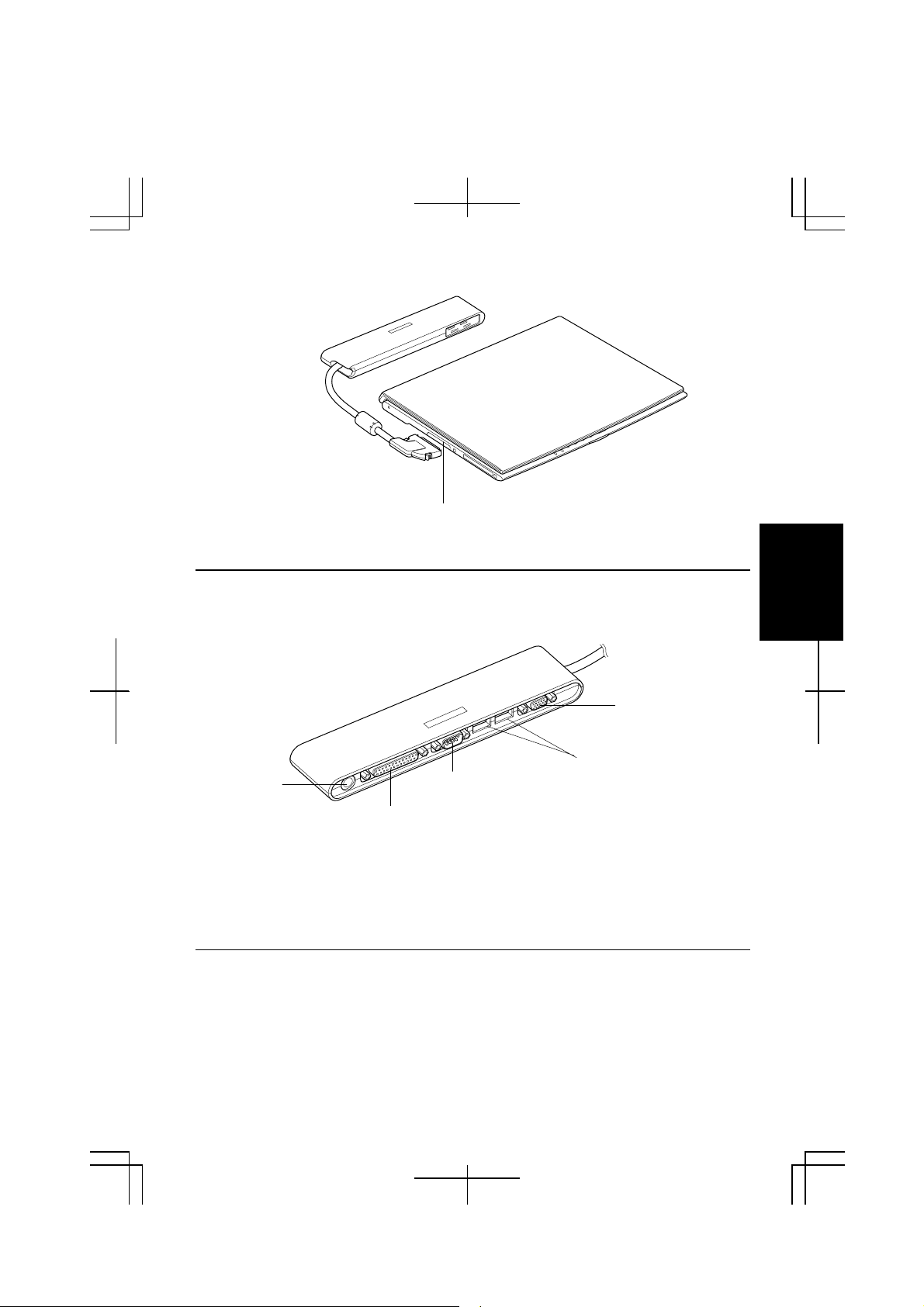
Using the Optional Port Bar
The optional port bar (CE-PB01) is a convenient station adding extra ports to your
computer. You can leave peripheral devices such as a printer or an external display
permanently connected to the port bar, and take your computer out of your office or
house. When you connect the port bar to your computer again, all the devices
connected are instantly available.
RS-232C
Serial Device
USB Devices
External Display
4
Printer
Connecting the Port Bar
Be sure to turn off the computer before connecting/disconnecting the port
bar. Otherwise the computer may malfunction.
1. Turn off the computer.
2. Remove the cover of the expansion port.
4-20
Page 68
3. Connect the cable of the port bar to the expansion port of the computer.
Expansion Port
4. Turn on the computer.
Using the Port Bar
All the ports available are located on the back of the port bar.
External Monitor Port
AC Adapter
Jack
Parallel Port
You can connect/disconnect the devices to/from the external monitor port, the USB
ports, and the parallel port while the computer is turned on.
When you use the serial port, be sure to connect the device to the port bar before
you turn on the computer.
Serial Port
USB Ports
Disconnecting the Port Bar
1. Turn off the computer and the devices connected to the port bar.
4
4-21
Page 69

4
2. Press the buttons on the both sides of the connector and remove the connector
form the expansion port.
3. Store the connector into the port bar.
4-22
Page 70

CHAPTER 5
Communication Functions
This chapter explains how to use the built-in modem and the LAN unit.
Built-in Modem
You can use the built-in modem for data transfer and fax communication.
• The built-in mod e m on your computer is designed on ly for regular
analog telephone lines. The modem may be damaged when connected
to a digital ISDN terminal or a digital PBX.
• Use TA (terminal adapter) to connect the built-in modem to a digital
telephone line.
• If an unusual device is attached to the line you are connecting to, the
modem may not function properly. Remove the device or contact the
dealer of the device.
• Before connecting to a PBX, consult the PBX maintenance staff or its
service company. If the electric characteristics of your PBX are
different from those of a regular analog line, the modem will not
function properly. If you connect the modem to a digital PBX, both the
modem and the PBX may be damaged.
Connecting the Modem to a Telephone Line
1. Turn off your c omputer.
(may not be available in some countries)
5
5-1
Page 71

5
2. Remove the cover of the modem jack on the right side of your computer.
To avoid damaging the modem, keep the modem cover, and attach it after
you finish using the built-in mo dem.
3. Connect one end of the included modem cable to the modem jack.
Do not connect the modem cable to the LAN jack next to the modem jack.
It may damage the LAN jack or the modem cable.
4. Connect the other end of the modem cable to the telephone line.
LAN jack
To Telephone Line
Modem Jack
5. Turn on the computer.
Connect the modem to the telephone line directly. Do not use a
distributor or allotter.
Configuring the Modem
Make the necessary adjustments as shown below.
1. From the
2. Double-click the
3. Select
4. Type in the details about your location and dialing properties and click OK.
5. Once you set one dialing property, you can make another new dialing properties
by clicking
5-2
Start
menu, select
Phone and Modem Options
New Location
New …
and typing a suitable name in
Settings
and click
-
Edit.
Control Panel
icon.
Location name.
.
Page 72

Internet Connection
Windows 2000 has a special
the internet with ease. Simply double-click on the
the Windows desktop. If you plan on connecting to the Internet by using the modem
to dial an Internet Service Provider (ISP), have your account information and dialup number ready before you begin the
Dial-Up Networking
To create other dial-up networking accounts:
1. On the Windows desktop, double-click
2. Click
3. Double-click
4. Follow the instruction of the
Hyper Terminal and Phone Dialer
You can find these applications by opening the
Accessories- Communications. HyperTerminal
terminals, for example, Bulletin Boards.
numbers for quick access.
Network and Dial-up Connections
Make New Connection
new account.
Internet Connection Wizard
Connect to the Internet
Internet Connection Wizard
My Computer
.
.
Make Connection Wizard
Start
menu and selecting
lets you connect to other computer
Phone Dialer
lets you store and dial
to help you to connect to
icon on
.
icon.
dialog box to create a
Programs
Modem Settings
The settings for your modem are pre-installed in the Windows 2000 installed on
your computer. I n normal circumstances you d o not have to make changes to the
modem settings. If you need to make changes follo w this p rocedure:
-
5
1. From the
2. Double-click
3. Use the
make changes if necessary.
Power Management
To use communication software, you may have to disable power management. See
Disabling Power Management
Start
menu, select
Phone and Modem Options
Modems
and
Settings
Advanced
in Chapter 3.
Control Panel
icon.
tabs to display the settings of your modem and
.
5-3
Page 73

5
• See also the manual or online help of the software you are using
• Within the communications software you are using, set the COM port
of the built-in modem to COM3
• Do not enter
software.
• The communication speed may vary depending on the traffic, local
telecommunications infrastructure, and ISP (Internet Service Provider)
infrastructure.
• Before commencing with fax communication, it is recommended that
you exit other application programs.
System standby/hibernate
while using communication
.
5-4
Page 74

LAN unit
You can connect to a LAN (Local Area Network) with the 100 Base-TX/10 Base-T
LAN unit on your computer. To activate the LAN unit, perform the following steps.
Use a LAN cable of the category 3 when connecting to 10 BASE-T LAN,
and the category 5 when connecting to 100 BASE-T LAN.
Connect your computer to LAN
1. Turn off the computer.
2. If your computer is provided with the LAN cable, go to the step 4. If with the
core for a LAN cable, go to the next step.
3. Attach the provided core to one end of your LAN cable. Insert the cable into
the core and close the core until it clicks.
4. Remove the cover of the LAN jack on the right side of your computer.
5
LAN Jack
Modem Jack
5. Connect the core end of the LAN cable into the LAN jack.
Do not connect the LAN cable to the modem jack next to the LAN jack. It
will damage the LAN cable and the modem jack.
6. Connect the other end of the LAN cable into the network hub.
7. Turn on the computer.
8. On the Windows desktop, double-click
My Computer
icon.
5-5
Page 75

5
9. Click
10. Right-click
11. From the pull-down menu, click
12. In the
If you cannot access the network,
1. From the
2. Double-click
3. Click
4. Double-click
5. Click
6. Click OK and close
7. Click OK and close Control Panel window.
Network and Dial-up Connections
Local Area Connection
Properties
Local Area Connection Properties
your network status. Refer to your network administrator.
If your computer is provided with a LAN cable, always use that LAN
cable. If your LAN cable has no core attached, please attach the provided
core before use.
Start
menu, select
System
Hardware
Advanced
select an appropriate value in
tab; then,
Network Adapters
tab, and select
Device Manager
Settings
icon.
Device Mana
; then,
Link Speed/Duplex Mode
Value
.
.
.
dialog box, set fields according to
Control Panel
-
ger… button.
Realtek RTL8139 xxxxx.
:.
window.
.
Property
in
: and
5-6
Page 76

CHAPTER 6
Setup Utility
This chapter describes how to run the Setup Utility to change settings on your
computer.
Running the Setup Utility
With the Setup Utility, you can customize the system configuration information,
such as time and date, port assignments, or passwords. The information you have
specified is saved in a special area called CMOS RAM, which the system reads
every time you turn on the computer. Your computer is shipped from the factory
with the appropriate setting of the Setup Utility. Leave it as default in normal use.
Contents of the Setup Utility
The Setup Utility consists of four menu pages, as follows:
•
Main: Configures basic setting
•
Advanced: Configures device interface (I/O ports, etc.)
•
Security: Sets Passwords
•
Exit: Exits the Setup Utility or returns to the default values
6
6-1
Page 77

Entering and Exiting the Setup Utility
1. Turn on the computer.
2. When
3. Change to the desired settings.
<F2> to enter SETUP
or → key : Selects the menu
←
or ↑ key : Selects the item
↓
Minus
In the item with mark, press
sub menu and return to the previous menu.
or
Space
key : Changes the value.
appears, press F2.
Enter
to open sub menu. Press
Esc
to close the
6
4. Select
5. Select one of the exit methods, and press
6. Confirm the message and press
Exit
.
Enter
again. The system restarts.
When the Setup Utility is open, power management does not work. Do not
close the display cover.
Enter
.
6-2
Page 78

Main Menu
System Time
hour format). Use
change numerals.
System Date
key to move the cursor, and minus key or space bar to change numerals.
Hard Disk Type
show the details.
Boot Sequence
menu. The system boots from the drive at the top of the list. If the system cannot
find the drive, it will boot from the second one; then, third one. Use arrow keys to
select the drive you want to move; then, use minus key or space bar to move it up
and down.
Internal Numlock
always disabled or not. (Num lock indicator will turn when Fn +
pressed regardless of this setting. An external keyboard will be numlocked if
connected. )
Memory Cache
enabled or disabled.
defines the system time, using the format
Tab
key to move the cursor, and minus key or space bar to
defines the system date, using the format
shows the type of the hard disk of your computer. Press
specifies where the system boots from. Press
defines whether the numlock keys of the built-in keyboard are
defines whether the primary cache or the secondary cache is
hour:minute:second
month/day/year.
Enter
Use
to open the sub
NumLk
are
(24-
Tab
Enter
to
6
USB Emulation
QuickBoot Mode
memory while booting, to shorten the boot time.
Quiet Boot
System Memory
Always set to 640KB.
Extended Memory
BIOS Version
defines whether a USB keyboard can be used in MS-DOS mode.
defines whether the system skips the check of the internal
defines whether the SHARP logo appears on the screen while booting.
shows the volume of the conventional memory used in MS-DOS.
shows the volume of the extended memory more than 1MB.
shows the BIOS version of the system.
6-3
Page 79

EC/KBC Version
system.
shows the EC or keyboard controller BIOS version of the
Advanced Menu
6
Serial port A
means that you can set the item by yourself.
automatically assigned.
Parallel port
address.
Mode
can be selected (
(Enhanced Parallel Port mode) or
the port.
Internal Pointing Device
Resolution Expansion
is 640x480 or 800x600.
Plug&Play O/S
Large Disk Access Mode
operating system such as UNIX, you may have to change the value to
sets the RS-232C serial port, selecting the base I/O address.
Auto
means that the item is
Disabled
sets the printer port, selecting the LPT port mode and the base I/O
Enabled
means that you can set the items by yourself.
Bi-directional, ECP
defines whether the screen is expanded when the resolution
Enabled
enables or disables plug & play function.
means that you cannot use the port.
Auto
(Extended Capabilities Port mode),
Output only
enables or disables the built-in glide pad.
means that the screen is expanded.
normally has to be as default,
Disabled
).
means that you cannot use
DOS
. If you install other
means the
Other
Enabled
EPP
.
6-4
Page 80

Security Menu
Set Supervisor Password
See the next section about the supervisor password.
Set User Password
section about the user password.
If you lose your password, you will be unable to access the computer or
change the configuration. Make sure to select a password you will never
forget, or write it down and protect it in a secure place. Otherwise, you
will have to contact your dealer fo r assistance.
Password on boot
computer.
Hard Disk boot Sector
protected. When formatting the hard disk or reinstalling software, set to
defines whether you have to type the password for booting the
defines the supervisor password (up to eight characters).
defines the user password (up to eight characters). See the next
defines whether the boot sector of the hard disk is write-
Normal
Supervisor and User Password
Setting a password will protect your computer against unauthorized access. When a
password is set, the system requires the password when entering to the Setup Utility.
Password on
And if
computer is turned on.
boot is enabled, the system will require a password when the
.
6
If you enter a wrong password three times, the message
appears. Press the power button to shut down the computer, and after 10
seconds, press the power button to turn it on again.
Your computer supports two different levels of password security: Supervisor
password and User password. You cannot set a user password unless you have set a
supervisor password. If you share the computer with others, we recommend that you
set both the supervisor and the user password, and let others know the user
password only.
If you type the user password when you enter the Setup Utility, you can change
System Time
Security
menu only.
System Date
and
of the
Main
menu, and
Set User Password
System Disabled
of the
6-5
Page 81

Setting the Password
1. In the
2. Type your password (up to eight characters), and press
3. Type the same password again, and press
4. Select
5. Confirm
Security
Set User Password
Exit
menu and confirm
Enter
.
Yes
Changing the Password
1. In the
2. Type your current password, and press
3. Type your new password, and press
4. Type your new password again, and press
5. Select
6. Confirm
Security
Set User Password
Exit
menu and confirm
Enter
.
Yes
6
menu of the Setup Utility, select
and press
is highlighted and press
menu of the Setup Utility, select
and press
is highlighted and press
Enter
.
Enter
Exit Saving Changes
Enter
Enter
.
Enter
Enter
Exit Saving Changes
Enter
Set Supervisor Password
Enter
twice.
is highlighted; then press
. The system restarts.
Set Supervisor Password
.
.
Enter
twice.
is highlighted; then press
. The system restarts.
or
.
or
Deleting the Password
1. In the
2. Type your current password, and press
3. Without typing any characters, press
4. Press
5. Select
6. Confirm
Security
Set User Password
Enter
Exit
Enter
menu of the Setup Utility, select
twice.
menu and confirm
Yes
is highlighted and press
and press
Enter
6-6
Set Supervisor Password
.
Enter
.
Enter
.
Exit Saving Changes
Enter
. The system restarts.
or
is highlighted; then press
Page 82

Exit Menu
Exit Saving Changes
Utility.
Exit Discarding Changes
have changed.
Load Setup Defaults
one of the above items.
Discard Changes
exit, select one of the above two items.
Save Changes
two items.
saves the settings you have changed and exits the Setup
exits the Setup Utility without saving the settings you
returns the values of all items to the default. To exit, select
returns the values of all items to the values you last saved. To
saves the settings you have changed. To exit, select one of the above
6
6-7
Page 83

6
6-8
Page 84
Appendixes
The appendixes contain additional information on the use and care of your
computer.
Converting File Format
The C: drive of your computer is formatted with FAT 32 when shipped from the
factory or after re-installation. The drive can be formatted with NTFS by following
the instructions below:
Converting to NTFS Format
Once formatted with NTFS, it cannot be re-formatted again. Re-install
the system if you want the drive formatted with FAT32.
1. Log on to the computer with the name of the administrator.
2. From the
3. Type
4. Type the volume label of your computer and press
5. Type Y and press
6. Type
7. From the
8. Select
CONVERTςC:ς/FS:NTFS
You can see the volume label of the C: drive by double-clicking My
Computer.
Exit
Restart
converted to NTFS.
menu, select
Start
Enter
and press
Start
Enter
menu, select
and click OK. The system restarts and the drive will be
Programs
.
.
Shut down….
–
Accessories
, and press
Enter
–
Command Prompt
.
.
Enter
.
Appendixes
Setting Security for NTFS Drive
1. Follow the steps 1 and 2 of the above section.
2. Type:
SECEDITς/CONFIGUREς/DBςC:\WINNT\TEMP.MDBς/CFGςC:\WINN
T\INF\DEFLTWK.INFς/AREASςFILESTORE
3. If you see the message
Task is completed
, type
, and press
and press
Exit
Enter
Enter
.
.
A-1
Page 85

Maintenance and Care
This appendix provides you with information on how to maintain the computer in
excellent working condition.
Cleaning the Computer
Cabinet
Apply a small amount of mild cleaning solution to a dry, lint-free cloth and wipe the
cabinet with the cloth.
• Never clean the computer while it is powered on.
• Do not use alcohol, benzene, thinner or other strong chemical agents
that may damage the cabinet.
Screen
The surface of the screen may become smeared and accumulate dust during use.
Avoid touching the sc reen with your fingers when using the system. Gently wipe the
surface of the screen with a soft cloth that has been dipped in a mild detergent
solution and squeezed dry.
Glide Pad
Wipe the glide pad with a soft, dry cloth.
Appendixes
Ventilation Openings
Dust on the ventilation openings may cause overheating of the computer. Wipe the
ventilation openings with a soft, dry cloth.
Traveling with the Computer
This computer is designed for portability. For safety and convenience when
traveling, please follow these guidelines.
•
Before traveling, back up your data on floppy disks or other external media.
•
Do not travel with an optional external floppy disk drive unit, optional external
CD-ROM drive or optional port bar connected.
•
Do not carry the computer powered on. This may result in loss of data and/or
damage to the hard disk drive.
•
Make sure the display cover is closed before traveling. Unless the cover may be
opened unawares, and the display or the keyboard will be damaged.
A-2
Page 86

•
If you carry the computer in a bag, try to avoid unnecessary pressure, caused by
the stuff of the bag, to the computer.
•
Disconnect the AC adapter from the computer.
•
Fully charge the standard battery pack and bring the AC adapter and the AC
power cord.
•
Avoid sudden shocks or extreme vibration.
A-3
Appendixes
Page 87

Re-installation Instructions
To recover your hard disk, you will use PowerQuest®EasyRestore™. Before starting reinstallation, read t he following End User License Agreement first.
PowerQuest(R) EasyRestore (TM) End User License Agreement
IMPORTANT: Read this before using your copy of PowerQuest software.
This document is a legal agreement between you, the "end user," and PowerQuest Corporation. Use of
the software indicates your acceptance of these terms. As used in this License Agreement, the term
"Software" means the EasyRestore software included on t he CD provid ed with this License Agreement .
1. PROPRIETARY RIGHTS. The Software is a proprietary product of PowerQuest Corporation
("PowerQuest") or its licensors and is protected under U.S. copyright laws and international treaty
provisions. Ownership of the Software and all copies, modifications, and merged portions thereof shall
at all times remain with PowerQuest or its licensors.
2. GRANT OF LICENSE. The Software is being licensed to you, which means you have the right to use
the Software only in accordance with this License Agreement. The Software contains pre-installed
Appendixes
software for disaster recovery purposes. The Software is only aut horized for distribution together with a
specific computer. This License authorizes you to use the Software for disaster recovery purposes only,
to restore the hard disk image contained on the CD to the computer with which the CD and Software
were originally shipped.
3. NONPERMITTED USES. Without the express permission of PowerQuest, you may not (a) use, copy,
modify, alter, or transfer, electronically or otherwise, the Sof tware or documentation except as expressly
permitted in thi s License Agreement, or (b) translate, reverse pr ogram, disassemble, dec o mpile, or
otherwise reverse engineer the Sof tware.
4. TECHNICAL SUPPORT. PowerQuest is NOT responsible to provide technical support. Any and all
technical support questions, regarding the Software, should be referred to the place of purchase.
5. U.S. GOVERNMENT RESTRICTED RIGHTS. If you are acquiring the Software on behalf of any
unit or agency of the United States Government, the following provision applies: It is acknowledged that
the Software and the documentation were developed at private expense and that no part is in the public
domain and that the Software and documentation are provided with RESTRICTED RIGHTS. Use,
duplication, or disclosure by the Government is subject to restrictions as set forth in subparagraph
A-4
Page 88

(c)(1)(ii) of the Rights in Technical Data and Computer Software clause at DFARS 252.227-7013or
subparagraphs (c)(1) and (2) of the Commercial Computer Software-Restricted Rights at 48 CFR
52.227-19, as applicable. Contractor/manufacturer is PowerQuest Corporation/P.O. Box 1911/Orem,
UT 84059.
6. NO WARRANTY. The Software is being provided to you AS IS. PowerQuest does not warrant the
Software to end users. If the Software fails to perform substantially in accordance with the
documentation provided to your hardware supplier, PowerQuest will repair or replace the copy of the
Software provided to your hardware supplier and will authorize your hardware supplier to provide such
repaired or replaced Software to you without charge.
7. LIMITATION OF LIABILITY. NEITHER POWERQUEST NOR ITS SUPPLIERS SHALL IN ANY
EVENT BE LIABLE FOR ANY DAMAGES WHATSOEVER ARISING OUT OF OR RELATED T O
THE USE OF OR INABILITY TO USE THE SOFTWARE, INCLUDING BUT NOT LIMITED TO
DIRECT, INDIRECT, SPECIAL, INCIDENTAL, OR CONSEQUENTIAL DAMAGES, AND
DAMAGES FOR LOSS OF BUSINESS PROFITS, BUSINESS INTERRUPTION, LOSS OF
BUSINESS INFORMATION, OR OTHER PECUNIARY LOSS, EVEN IF POWERQUEST
CORPORATION HAS BEEN ADVISED OF THE POSSIBILITY OF SUCH DAMAGES, WHETHER
SUCH LIABILITY IS BASED ON CONTRACT, TORT, WARRANTY, OR ANY OTHER LEGAL OR
EQUITABLE GROUNDS. BECAUSE SOME STATES DO NOT ALLOW THE EXCLUSION OR
LIMITATION OF LIABILITY FOR CONSEQUENTIAL OR INCIDENTAL DAMAGES, THE ABOVE
LIMITATION MAY NOT APPLY TO YOU.
8. NO WAIVER. Any failure by either party to this agreement to enforce a specific part of the
agreement in a specific situation is not a waiver of rights under the agreement. The party may still
enforce the r est of the agreem ent in that situation a nd may still enforce some or all of the agreement in
other situations.
9. This License Agreement constitutes the entire agreement between you and PowerQuest pertaining to
its subject matter. This License Agreement is governed by the laws of the State of Utah. Any litigation
arising from this license will be pursued only in the state or federal courts located in the State of Utah.
Copyright 1994-2000, PowerQuest Corporation. All rights reserved. U.S. Patents 5,675,769; 5,706,472;
and 5,930,831; other patents pending in the U.S.A. and elsewhere. PowerQuest is a registered
trademark and EasyRestore is a trademark of PowerQuest Corporation.
A-5
Appendixes
Page 89

Preparation for Re-installation
You can format the hard disk and re-install the preinstalled software with the
recovery CD-ROM, and set the status of your computer to the same configuration as
shipped from the factory. Necessary for re-installation are the following:
•
Optional external CD-ROM drive unit (CE-CD05)
•
Product Recovery CD-ROM disks
•
Operatio n Manual
• It will take about 40 minutes to complete the re-installation. The time
depends on the data transfer rate of the CD-ROM drive you are using.
• It takes about ten seconds for the system to recognize a CD-ROM. If
you operate too quickly, an error message may appear. In this case,
return to the first step and repeat the installation
• Use the Product Recovery CD-ROMs only for your computer
• The Product Recovery CD-ROMs are not for sale. Keep them in a
secure place.
• Unless otherwise specified, the instructions in this booklet assume
that you are installing Windows 2000 into the C:\WINNT directory
Appendixes
Backing up the data
.
.
.
Before formatting the hard disk, you should back up your data. For details on how
to back up your data, see the Windows Online Help.
Although the pointer may be shown on the screen, never touch the
keyboard or the mouse during recovery except when the message prompts
you to. If you touch them, the re-installatio n will be canceled. In this
case, not only C: drive but also D:drive will be formatted .
Selecting the way to recover your system
Your computer has two drives(C: and D:) when it was shipped from the factory.
You can select the way to recover your system.
•
Recovers C: drive only. (Recommended)
This process will format C: drive only and recover C: drive to the same status as
A-6
Page 90

shipped from the factory. Nothing will be performed to D: drive. The volume of
the drives will not be changed and keep current ones.
•
Recovers both C: and D: drive
This process will format both C: and D: drive, and contents of the hard disk is
restored to its original state in C: drive. The volume of the drives will be back
to the same as shipped from the factory.
•
Formats hard disk and creates new partition
This process will format whole hard disk drive and creates new partition. You
can select the volume of C: and D: drive. The contents of the hard disk are
restored to its original state in C: drive.
Formatting the drives and re-installing Windows 2000
Make sure the computer is turned off.
1.
If any peripheral devices, except the optional external CD-ROM drive unit
2.
(CE-CD05), are connected to your computer, disconnect them.
Turn on the computer.
3.
When the message
4.
Utility opens.
Insert the Product Recovery CD-ROM disk 1 into the CD-ROM drive.
5.
In the
6.
In
7.
8.
9.
10. If you selected
11. Read the message and select
12. If you selected
13. If you see the message asking you to insert the Product Recovery CD-ROM
Boot Sequence
In the
Enter
Read the message on the screen, and select the way to recover your system;
then, press
volume of C: drive and press
message and select
message and select
to the next step.
disk 2, remove the disk 1 and insert the disk 2; then, press
menu, select
Exit
menu, confirm
Exit
twice. The system restarts.
Enter
Press <F2> to enter SETUP
Load Setup Defaults
of the
.
Formats hard disk and creates new partition
Continue
Formats hard disk and creates new partition
Continue
menu, set
Main
Exit Saving Changes
. If selected another menu, read the
Enter
; then, press
Continue
; then, press
; then, press
appears, press F2. The Setup
; then, press
CD-ROM Drive
is highlighted and press
.
Enter
. If selected another menu, go
Enter
Enter
to the top of the list
, select the
.
Enter
, read the
Enter
twice.
.
Appendixes
.
A-7
Page 91

14. If you see the message
remove the Product Recovery CD-ROM disk 2. The system will restart
automatically.
15. When the message
Utility opens.
16. In the
17. In the
Enter
18. Set up Windows 2000, following the instructions on the screen. When you
finish the setup, the recovery is completed.
menu, select
Exit
menu, confirm
Exit
twice. The system restarts.
The hard disk has been recovered successfully
Press <F2> to enter SETUP
Load Setup Defaults
Exit Saving Changes
appears, press F2. The Setup
; then, press
is highlighted and press
Enter
,
twice.
Appendixes
A-8
Page 92

Index
A
AC adapter
connecting, 1-3
using, 2-2
Audio
connecting audio equipment, 4-14
B
switching the display, 2-6, 4-12
troubleshooting, T-3
turning off, 2-7
E
External monitor
connecting, 4-11
disconnecting, 4-12
switching the display, 2-6, 4-12
Battery pack
changing, 3-4
charging, 3-2
checking level, 3-2
indicator, 2-1, 3-3
initializing, 3-3
low battery indication, 3-3
Optional battery pack, 3-7
C
Cleaning
computer, A-2
optional CD-ROM drive unit, 4-10
CD-ROM drive unit (external/optional)
connecting, 4-7
mode switch, 4-10
disconnecting, 4-10
troubleshooting, T-5
CD
handling, 4-8
inserting, 4-8
playing, 4-10
removing, 4-9
D
Display
changing brightness, 2-6,7
changing resolution, 4-12
changing number of colors, 4-12
F
floppy disk
handling, 4-3
inserting, 4-4
removing, 4-5
formatting, 4-5
Floppy disk drive unit (external/optional)
connecting, 4-3
troubleshooting, T-4
disconnecting, 4-5
G
Glide pad
changing configuration, 2-5
clicking and double-clicking, 2-5
drag and drop, 2-5
scroll, 2-5
troubleshooting, T-4
H
Hard disk drive
troubleshooting, T-5
I
Indicators
power and battery, 2-1
Index
Index-1
Page 93

K
Keyboard
function keys, 2-6
special keys, 2-6
troubleshooting, T-4
windows keys, 2-6
L
LAN
configuring, 5-5
connecting to network, 5-5
troubleshooting, T-5
M
Port bar (optional)
connecting, 4-20
disconnecting, 4-21
ports, 4-21
using, 4-21
Power
choosing AC or battery, 2-1
indicator, 2-1
Power management
controlling CPU speed, 3-9
disabling, 3-12
stopping power supply to hard disk, 3-8
stopping power supply to display, 3-8
system hibernate, 3-9
system standby, 3-9
Printer, 4-19
Modem
configuring, 5-2
connecting to telephone line, 5-1
settings, 5-3
troubleshooting, T-5
Passwords
changing, 6-6
deleting, 6-6
setting, 6-6
Supervisor, 6-5
User, 6-5
PC cards
inserting, 4-16
ejecting, 4-18
Index
using, 4-16
Peripherals
audio equipment, 4-14
connecting guidelines, 4-1
external monitor, 4-11
external CD-ROM drive, 4-6
external floppy disk drive, 4-3
headphones, 4-15
microphone, 4-15
PC cards, 4-16
port bar (optional), 4-20
printer, 4-19
troubleshooting, T-6
USB device, 4-16
R
Resetting
power button, 2-3
reset switch, 2-3
P
Setup utility
advanced menu, 6-4
entering and exiting, 6-2
exit menu, 6-7
main menu, 6-3
running, 6-1
security menu, 6-5
using, 6-1
Speedstep technology, 3-9
System Standby
about, 3-9
generating conditions, 3-10
resuming from, 3-9
System Hibernate mode
about, 3-9
generating conditions, 3-10
resuming from, 3-9
supporting, 3-10
Status indicators, xvii
S
T
Troubleshooting
Index-2
Page 94

common problems, T-1
communications, T-5
display, T-3
floppy disk drive, T-4
hard disk drive, T-5
keyboard or glide pad, T-4
peripherals, T-6
reference, T-1
U
USB device, 4-16
W
Windows 2000
changing user name, 2-8
changing user password, 2-8
first-time setup, 1-5
properties dialog boxes, 1-6
registering user, 2-8
Index-3
Index
Page 95

Index
Index-2
 Loading...