

Page 1

Notice for All Users
• Consult the operation manual for proper use of your computer.
• The product and the accessories are subject to change without prior notice.
• SHARP assumes no guarantee for results arising from use of pre-installed and
third party software. Consult the software vendor for resolution of problems.
(Read the service condition of the software before use.)
• SHARP assumes no responsibility for problems caused by incorrect handling,
repairs, defects, battery replacement or any other cause.
i
Page 2

Notice for Users in the USA
FCC Statement
WARNING - FCC Regulations state that any unauthorized changes or modifications
to these equipments not expressly approved by the manufacturer could void the user’s
authority to operate these equipments.
Note: These equipments have been tested and found to comply with the limits for a
Class B digital device pursuant to Part 15 of the FCC Rules.
These limits are designed to provide reasonable protection against harmful interference in
a residential installation. These equipments generate, use and can radiate radio frequency
energy and, if not installed and used in accordance with the instructions, may cause
harmful interference to radio communications. However, there is no guarantee that
interference will not occur in a particular installation. If these equipments do cause
harmful interference to radio or television reception, which can be determined by turning
the equipments off and on, the user is encouraged to try to correct the interference by one
or more of the following measures:
• Reorient or relocate the receiving antenna.
• Increase the distance between the equipment and receiver.
• Connect the equipment into an outlet on a circuit different from that to which the
receiver is connected.
• Consult the dealer or an experienced radio/TV technician for help.
A shielded I/F cable is required to insure compliance with FCC regulation for Class B
computing equipment.
* As an ENERGY STAR
the ENERGY STAR
Declaration of Conformity
SHARP PERSONAL COMPUTER, PC-MM Series
This device complies with part 15 of the FCC rules. Operation is subject to the following
conditions: (1) this device may not cause harmful interference, and (2) this device must accept
any interference received, including interference that may cause undesired operation.
Responsible Party: SHARP ELECTRONICS CORPORATION
Sharp Plaza, Mahwah, New Jersey 07430-2135
TEL: 1-800-BE-SHARP
®
Partner, SHARP has determined that this product meets
®
guidelines for energy efficiency.
ii
Page 3

FCC Radiation Exposure Statement
The available scientific evidence does not show that any health problems are associated
With using low power wireless devices. There is no proof, however, that these low
power wireless devices are absolutely safe. Low power Wireless devices emit low
levels of radio frequency energy (RF) in the microwave range while being used.
Whereas high levels of RF can produce health effects (by heating tissue), exposure to
low level RF that does not produce heating effects causes no known adverse health
effects. Some studies have suggested that some biological effects might occur, but such
findings have not been confirmed by additional research. PC-MM20 has been tested
and found to comply with the Federal Communications Commission (FCC) guidelines
on radio frequency energy (RF) exposure. The maximum SAR levels tested for the PCMM20 has been shown to be W/kg at Body.
iii
Page 4

Notice for PC Card Modem
FCC Part 15 Subpart B Statement
WARNING - FCC Regulations state that any unauthorized changes or modifications
to this equipment not expressly approved by the manufacturer could void the user’s
authority to operate this equipment.
Note: This equipment has been tested and found to comply with the limits for a Class
B digital device pursuant to Part 15 of the FCC Rules.
These limits are designed to provide reasonable protection against harmful interference in a
residential installation. This equipment generates, uses and can radiate radio frequency
energy and, if not installed and used in accordance with the instructions, may cause harmful
interference to radio communications. However, there is no guarantee that interference will
not occur in a particular installation. If this equipment does cause harmful interference to
radio or television reception, which can be determined by turning the equipment off and on,
the user is encouraged to try to correct the interference by one or more of the following
measures:
Reorient or relocate the receiving antenna.
Increase the distance between the equipment and receiver.
Connect the equipment into an outlet on a circuit different from that to which the
receiver is connected.
Consult the dealer or an experienced radio/TV technician for help.
Declaration of Conformity
Zoom PC Card Modem: Model 1273
This device complies with part 15 of the FCC rules. Operation is subject to the following
conditions : (1) this device may not cause harmful interference, and (2) this device must accept
any interference received, including interference that may cause undesired operation.
Responsible Party:
Zoom Telephonics, INC
207 South Street Boston, MA 02111
TEL: 617-423-1072
FCC Part 68 Statement
This equipment complies with Part 68 of the FCC rules. On the bottom of this
equipment is a label that contains, among other information, the FCC registration
number and ringer equivalent number (REN) for this equipment. If requested, this
number must be provided to the telephone company.
The modem jack of this equipment complies with Sub-part F of Part 68 of FCC rules.
iv
Page 5

The REN is used to determine the quantity of devices which may be connected to the
telephone line. Excessive RENs on the telephone line may result in the devices not
ringing in response to an incoming call. In most, but not all areas, the sum of the
RENs should not exceed five (5.0). To be certain of the number of devices that may
be connected to the line, as determined by the total RENs contact the telephone
company to determine the maximum REN for the calling areas.
If the terminal equipment causes harm to the telephone network, the telephone
company will notify you in advance that temporary discontinuance of service may be
required. But if advance notice isn't practical, the telephone company will notify the
customer as soon as possible. Also, you will be advised of your right to file a
complaint with the FCC if you believe it necessary.
The telephone company may make changes in its facilities, equipment, operations, or
procedures that could affect the operation of the equipment. If this happens, the
telephone company will provide advance notice in order for you to make the
necessary modifications in order to maintain uninterrupted service.
If trouble is experienced with this equipment, please contact Zoom Telephonics, Inc.
for repair and (or) warranty information (Refer to the provided Consumer Limited
Warranty sheet). If the trouble is causing harm to the telephone network, the
telephone company may request you remove the equipment from the network until
the problem is resolved.
The equipment cannot be used on public coin service provided by the telephone
company. Connection to Party Line Service is subject to state tariffs. (Contact the
state public utility commission, public service commission or corporation
commission for information.)
The Telephone Consumer Protection Act of 1991 makes it unlawful for any person to
use a computer or other electronic device, including fax machines, to send any
message unless such message clearly contains in a margin at the top or bottom of
each transmitted page or on the first page of the transmission, the date and time it is
sent and an identification of the business or other entity, or other individual sending
the message and the telephone number of the sending machine or such business, other
entity, or individual. (The telephone number provided may not be a 900 number or
any other number for which charges exceed local or long-distance transmission
charges.) To program this information, refer to the manual of the communication
software.
v
Page 6

Product Information and Customer Assistance
For Product Information and Customer Assistance:
Call: 561-997-9686
Zoom Telephonics, INC
207 South Street Boston, MA 02111
Home Page: http://www.zoom.com
ZOOM PCMCIA Modem card does not support Microsoft Windows XP fax send and
receive functionality. For more information, please contact 1-800-BE-SHARP.
Warning
This product utilizes tin-lead solder, and fluorescent lamp containing a small amount
of mercury.
Disposal of these materials may be regulated due to environmental considerations.
For disposal or recycling information, please contact your local authorities or the
Electronics Industries Alliance: www.eiae.org
Copyright
It is the intent of Sharp that this product be used in full compliance with the copyright
laws of the United States and that prior permission be obtained from copyright
owners whenever necessary.
vi
Page 7

CAUTION:
TO PREVENT ELECTRICAL SHOCK, DISCONNECT THE AC ADAPTER AND
REMOVE THE BATTERY BEFORE SERVICING.
CAUTION:
FOR A COMPLETE ELECTRICAL DISCONNECTION, UNPLUG THE POWER
CORD AND THE BATTERY.
VORSICHT:
UM DIE STROMZUFUHR VOLLSTÄNDIG ZU UNTERBRECHEN, DEN
NETZSTECKER HERAUSZIEHEN UND DIE BATTERIE ÈNTFERNEN.
ATTENTION:
POUR UN ARRET TOTAL DU SYSTEME, DECONNECTEZ LA PRISE DE
COURANT SECTEUR ET LA BATTERIE.
VARNING:
FÖR TOTAL ELEKTRISK URKOPPLING, KOPPLA UR KONTAKTEN OCH TA
UR BATTERIET.
PRECAUCION:
PARA UNA COMPLETA DESCONEXION ELECTRICA DESENCHUFE LA
CLAVIJA DE LA RED Y LA BATERIA.
vii
Page 8

Safety Precautions
General
• Follow all cautions and instructions marked on your computer.
• Except as described elsewhere in this manual, refer all servicing to qualified
personnel. Immediately shut off your computer and seek servicing under the
following conditions:
• when the power cord or plug is damaged or frayed
• when liquid is spilled on your computer
• when your computer has been dropped or the cabinet has been damaged
Location
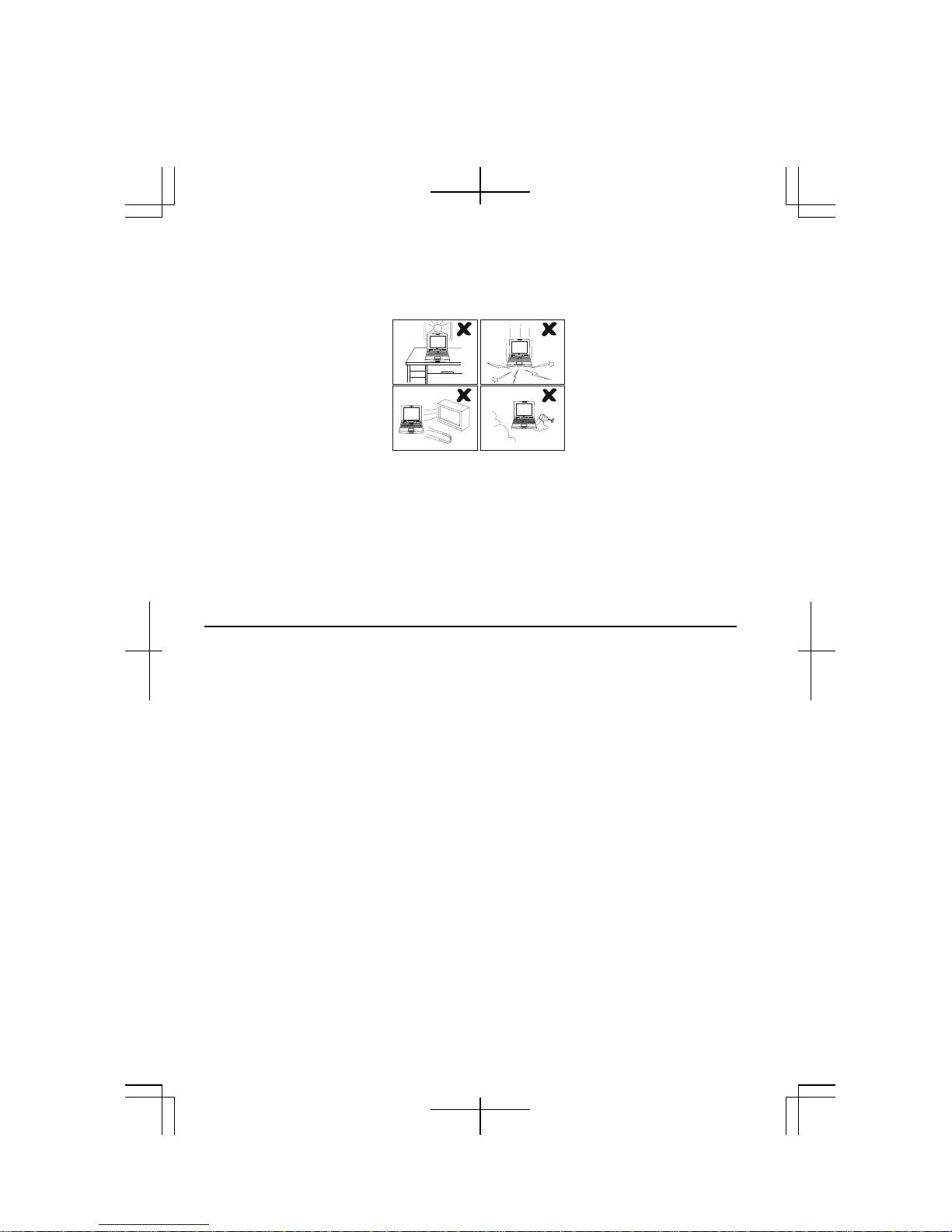
• Do not expose your computer to direct sunlight.
• Try to avoid dusty environments.
• Keep your computer away from any magnetic devices and TVs.
• Keep your computer away from heaters.
• Keep your computer away from excessive humidity or fluids such as rain, snow,
water spray, juice, coffee, steam, etc.
• Keep your computer away from extremely high or low temperature.
• Do not move your computer from an extremely cold place to an extremely warm
place. A temperature difference of more than 18°F (10°C) will cause condensation
inside the unit, which may cause damage. (In this case, turn off your computer and
leave it for about an hour to completely dry the unit.)
• Do not block or cover slots or openings on the cabinet. They protect your
computer from overheating.
• Do not place your computer on an unstable or uneven work surface.
• Care should be exercised when using on heat sensitive surfaces or your lap as the
base of your computer will get hot.
• Do not use your computer on your lap or any part of your body for an extended
period during operation or charging to avoid injury from heat exposure.
Usage
• Never push any objects into cabinet openings. They may touch dangerous voltage
points or short parts that could result in fire or electrical shock.
• Do not press or place heavy objects on your computer. Strong pressure can
damage the cabinet or make your computer fail.
• If your computer or the AC power cord experiences an abnormal situation such as
heat generation or smoking, or produces an abnormal odor, turn off your computer,
unplug the power cord, and remove the battery pack immediately.
• Turn off your computer before installing or removing any peripheral devices
except when connecting USB devices, a PC card, etc.
viii
Page 9
• Never subject your computer to sudden shocks or extreme vibration.
• Do not drop your computer or hit it with other equipment.
• Do not scratch the surface of the LCD screen.
• Turn off your computer and disconnect the AC power cord before cleaning.
• When carrying your computer:
• Turn off your computer.
• Remove external media such as a PC card from the slot.
• Disconnect the external peripherals, cables and cords if connected.
• Do not give shock to your computer.
• Do not hold the display unit.
Otherwise, the hard disk may fail or the stored data might be lost.
Battery Pack Precautions
CAUTION
DANGER OF EXPLOSION IF BATTERY IS INCORRECTLY REPLACED.
REPLACE ONLY WITH THE SAME OR EQUIVALENT TYPE
RECOMMENDED BY THE MANUFACTURER. DISCARD USED BATTERIES
ACCORDING TO THE MANUFACTURER'S INSTRUCTIONS.
Handling
• Never put the battery pack in a fire, as it could explode and cause injury.
• Do not attempt to open or alter the battery pack.
• Do not place the battery pack where it might get hotter than 140°F (60°C).
• The battery pack must be kept from metal objects such as jewelry and liquids.
They might trigger a short circuit and consequently cause the battery pack to heat
up and explode.
• Do not allow liquids to come in contact with the battery pack.
• Care must be taken not to drop the pack. A violent shock damages the pack.
• Do not solder anything to the battery terminals.
ix
Page 10

Charging
• Charge the battery pack only with the AC adapter and AC power cord included
with your computer.
Discharging
• Do not use the battery pack for any other purpose than powering your computer.
Storage
• Store the battery pack in a cool and dry place. Do not store it at temperatures
above 140°F (60°C).
• Recharge the stored battery pack before using it.
AC Power Precautions
• Plug the AC power cord directly in the wall jack. Plugging too many leads into a
single socket may result in fire.
• Never plug in or remove the AC power cord or AC adapter with wet hands for
prevention of electric shock.
• The included AC power cord must be appropriate for the voltage used in your area.
Using an inappropriate cord can cause fire.
• Unplug the AC power cord when not using your computer for a long period.
• Never disassemble, repair, or modify the AC adapter.
• Never modify, twist, forcibly bend or pull, or place heavy objects on top of the AC
cord to avoid damaging it. Using a damaged cord can cause fire or electric shock.
• Be sure to hold the plug of the AC power cord when removing it from a wall
socket.
• Check the AC power cord and power connectors periodically for damage. Change
the power cord immediately if damage is found.
Modem Precautions
IMPORTANT SAFETY INSTRUCTIONS
When using your telephone equipment, basic safety precautions should always be
followed to reduce the risk of fire, electric shock and injury to persons, including the
following:
• Do not use this product near water, for example, near a bath tub, wash bowl,
kitchen sink or laundry tub, in a wet basement or near a swimming pool.
• Avoid using a telephone (other than a cordless type) during an electrical storm.
There may be a remote risk of electric shock from lightning.
• Do not use the telephone to report a gas leak in the vicinity of the leak.
• Never install telephone wiring during lightning storms.
x
Page 11

• During thunder storms, you should turn off your computer, unplug the AC power
cord and remove the modem cable from your computer.
• Never install telephone jacks in wet locations unless the jack is specifically
designed for wet locations.
• Never touch uninsulated telephone wires or terminals unless the telephone line has
been disconnected at the network interface.
• Use caution when installing or modifying telephone lines.
Wireless LAN Precautions
• Disable the integrated antenna and do not communicate with wireless LAN in
specific environments where radio-susceptible equipment is nearby, on airplanes,
in hospitals, for example.
• Disable the integrated antenna and do not communicate with wireless LAN in
crowded places for prevention of cardiac pacemaker interference.
• Maintain a space of at least 8.66” (22cm) between a cardiac pacemaker and an
active wireless LAN antenna.
• Never disassemble or alter the wireless LAN unit.
• Do not remove the certification label on the wireless LAN unit.
Product Conformance
The wireless LAN unit equipped with your computer is in conformance with federal
requirements. No license is required for use of the device.
Notice of Radio Interference
The wireless LAN card equipped with your computer operates at 2.4GHz that is also
used for microwaves, science or medical devices, other similar radio stations
(hereafter called “other radio stations”), etc.
• Prior to using the wireless LAN function with your computer, confirm that no
“other radio stations” are operating nearby.
• If interference with “other radio stations” is experienced, change the current
channel set to your computer or move your computer. If it fails, stop operating.
xi
Page 12

PC Disposal or Transfer
Prior to the disposal or transfer of your computer, you should erase the data from
hard disks.
To remove the data from your hard disk drive, you will need to:
• “Delete” the data by placing it in your recycle bin.
• Empty the recycle bin.
• Format the hard drives.
• Recover the system.
The above procedures do not completely delete all data from your hard disks.
When a file is deleted, the disk location where it is stored is marked as unallocated
space available for new data. However, the old data is still there and can be recovered
unless new data is written. Because of the reason, malicious persons can recover the
“deleted” data and misuse it. To avoid the data spillage, users must thoroughly erase
all the data from the hard disks.
The following measures are recommended for permanent data deletion:
• Use special software or paid services for thoroughly erasing data
• Hammer, or strongly magnetize, the hard disk to destroy the stored data
Be sure to delete the software, such as operating system(s) or applications, on your
hard disk when transferring your computer, to avoid conflict with the software
agreement(s).
Other Precautions
• Periodic back-up copies of your important data should be made to protect your
data in the event of hard disk failure or loss of the data. Use other storage devices
for the backup.
(Data loss or alternation can be caused by: malfunction, repair or misuse of your
computer: improper change of the battery pack: damage by static electricity or
electrical noise.)
xii
Page 13
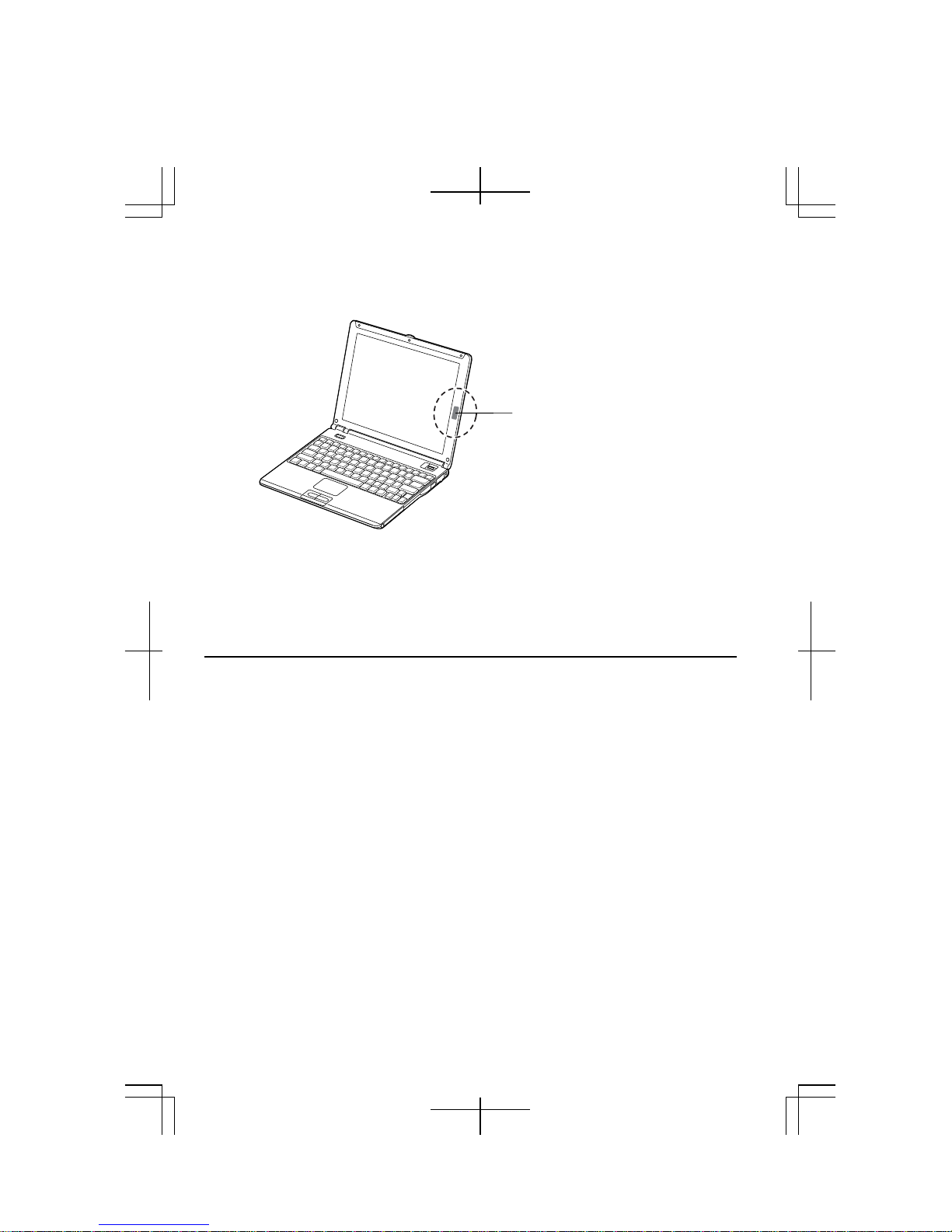
• Your computer is integrated with a magnet on the right side of the display. Be sure
to keep magnetic cards and floppy disks away from the right side of your
computer to prevent the data on the cards or floppy disks from being erased.
Magnet
• This computer has a sensor on the right side of the keyboard that responds to the
magnet. If the magnet gets close to the sensor:
• The backlight will be turned off.
• The system may enter the standby or the hibernate mode depending on the
setting. (See Chapter 3.)
For Your Health
• Take regular breaks of ten to fifteen minutes after every hour of continuously
viewing the screen to relieve your eyes.
• Adjust the brightness for comfortable viewing. (Brightness level of about 500 lux
is recommended.)
• Do not use your computer in an environment where sunlight or indoor lighting
reflects off the screen.
• Position the display slightly below eye level and give a space of 15.7” (40cm)
through 23.6” (60cm) between you and the display.
xiii
Page 14

Notice of Security with Wireless Devices
Wireless LAN provides data transfer by means of electric waves instead of LAN
cables between communicating devices such as personal computers and a wireless
LAN station. Wireless LAN has an advantage of simple and ubiquitous LAN
connection in the ranges where electric waves are available.
Since electric waves can penetrate through walls and reach everywhere, wireless
LAN includes some security threats and can produce the situations mentioned below
without proper security settings.
• Eavesdropping
Malicious third parties can intercept the transmission and monitor your mail to
obtain personal information such as an identification number, password, and
credit card number.
• Intruding
Malicious third parties can connect to a personal or office network without
authorization and illegally perform the following:
• Obtaining access to confidential customer records or sensitive corporate
information (Information leakage)
• Faking the original information (Spoofing)
• Altering the monitored original data and transmitting (Falsification)
• Spreading computer viruses resulting in the destruction of data or systems
(Destruction)
Although wireless LAN cards and wireless LAN stations (Access Points) have
security measures against the threats above, no security settings may have been
configured at the time of purchase.
All security features must be configured according to reference manuals of the
wireless LAN devices, which results in reduced opportunities for the situations
described above.
Use with a clear understanding that wireless LAN includes vulnerabilities that could
allow attackers to simply bypass security features.
Security measures are important for all users to understand for a safe use of wireless
LAN. SHARP encourages all users to configure the security settings with their own
judgment and responsibility.
xiv
Page 15

About This Manual
Notice
Information in this manual is subject to change without notice and does not represent a
commitment on the part of SHARP Corporation and its sales subsidiaries.
SHARP Corporation and its sales subsidiaries shall not be liable for technical or editorial
errors or omissions contained herein; nor for incidental or consequential damages resulting
from the furnishing, performance, or use of this material.
SHARP strongly recommends that separate permanent written records be kept of all important
data. Data may be lost or altered in virtually any electronic memory product under certain
circumstances. Therefore, SHARP assumes no responsibility for data lost or otherwise
rendered unusable whether as a result of improper use, repairs, defects, battery replacement,
use after the specified battery life has expired, or any other causes.
SHARP assumes no responsibility directly or indirectly, for financial losses or claims from
third persons resulting from the use of this product and any of its functions, such as stolen
credit card numbers, the loss of or alteration of stored data, etc.
Copyright
© 2004 SHARP Corporation
This document contains or refers to proprietary information which is protected by copyright.
All rights are reserved. Copying or other reproduction of this document is prohibited without
the prior written permission of SHARP Corporation.
Trademarks
Transmeta and Efficeon are trademarks of Transmeta Corporation.
ATI and Mobility RADEON are trademarks of ATI Technologies Inc.
IBM is a registered trademark of International Business Machines Corporation.
Microsoft and Windows are registered trademarks of Microsoft Corporation in the United
States and other countries.
Power Quest is a registered trademark and EasyRestore is a trademark of PowerQuest
Corporation.
BAPCo is a registered trademark of the Business Applications Performance Corporation.
MobileMark is a trademark of the Business Applications Performance Corporation.
All other brand and product names are trademarks or registered trademarks of their respective
holders.
xv
Page 16
Recording Important Information
For future reference, please record the following information in the spaces provided
below.
Model Number:
Serial Number:
Date of purchase:
Dealer’s Name:
Place of purchase:
Password:
The serial number is printed on a sticker located on the bottom of the computer.
xvi
Page 17
Manual Conventions
This manual uses a set of style conventions described below.
Notes and Cautions are italicized with icons:
A note icon informs you of a special technique or information that may
help you perform a task or better understand a process.
A caution icon alerts you to something that may cause problems or
damage to hardware, software or data.
Key Labels on the Keyboard, when referred to in the instructions, are shown in
boldface:
Press Enter to continue.
When two or more keys are separated by a plus (+) sign, press and hold down the first
key(s), and then press the second key:
Run Task Manager by pressing Ctrl+Alt+Delete.
Sample Entries are shown in lower cases of different typeface.
c:\windows\system
Words/Texts on Screen, such as window titles or possible parameters, are italicized:
Double-click this icon to display the Power Options Properties dialog box.
Set the item to Enabled.
Screens reproduced in this manual may differ slightly from the screens you see on
your computer.
Section Titles in other parts of this manual are italicized:
Refer to Installing Battery Pack section of Chapter 1.
xvii
Page 18

Table of Contents
Notice for All Users ..................................................................................................i
Notice for Users in the USA.....................................................................................ii
Notice for PC Card Modem......................................................................................iv
Safety Precautions..................................................................................................viii
Notice of Security with Wireless Devices..............................................................xiv
About This Manual..................................................................................................xv
Recording Important Information...........................................................................xvi
Manual Conventions..............................................................................................xvii
Table of Contents ...................................................................................................xiii
Overview of Computer...........................................................................................xxi
Quick Setup
Installing Battery Pack ...........................................................................................1-1
Connecting to AC Power Source............................................................................1-4
Setting Up Windows ..............................................................................................1-6
Turning Off Your Computer ..................................................................................1-8
Basic Operations
Choosing Power Source .........................................................................................2-1
Resetting System....................................................................................................2-3
Using Glide Pad .....................................................................................................2-4
Using Keyboard......................................................................................................2-7
Controlling Volume................................................................................................2-8
Adjusting Display.................................................................................................2-10
Sharing Your Computer .......................................................................................2-12
Battery and Power Management
Battery Pack ...........................................................................................................3-1
Power Management................................................................................................3-8
xviii
Page 19

Peripherals
Peripheral Device Connectors................................................................................4-1
Optional External Floppy Disk Drive Unit ............................................................4-3
Optional External CD-ROM Drive Unit ................................................................4-6
Display .................................................................................................................4-11
Audio System.......................................................................................................4-15
USB Device..........................................................................................................4-17
PC Card................................................................................................................4-18
Printer...................................................................................................................4-21
Communication Functions
LAN Unit ...............................................................................................................5-1
Wireless LAN.........................................................................................................5-5
Network Setup Utility ..........................................................................................5-12
Modem Card .......................................................................................................5-14
Setup Utility
Running Setup Utility ............................................................................................6-1
Main Menu.............................................................................................................6-3
Advanced Menu .....................................................................................................6-4
Security Menu........................................................................................................6-4
Boot Menu..............................................................................................................6-6
Exit Menu...............................................................................................................6-6
Connection Cradle
Overview of Connection Cradle ............................................................................7-3
Connecting to Host Computer................................................................................7-6
Synchronizing MM series with Host Computer...................................................7-11
Stopping Connection from Host Computer.......................................................... 7-15
Removing from Connection Cradle .....................................................................7-17
Setting Password..................................................................................................7-18
xix
Page 20

Appendixes
Maintenance and Care...........................................................................................A-1
Virus Infection Protection .....................................................................................A-3
Data Backup And Restore .....................................................................................A-6
Re-installation Instructions....................................................................................A-7
Troubleshooting
Common Problems ................................................................................................ T-1
Trouble when Starting........................................................................................... T-2
Trouble with Display............................................................................................. T-3
Trouble with Keyboard/Glide Pad......................................................................... T-4
Trouble with Floppy Disks.................................................................................... T-4
Trouble with Hard Disk......................................................................................... T-5
Trouble with CD.................................................................................................... T-5
Trouble with Communication................................................................................ T-5
Trouble with Peripherals ....................................................................................... T-9
Trouble with Connection Cradle ......................................................................... T-10
Other Troubles..................................................................................................... T-11
Index ...........................................................................................................Index-1
xx
Page 21
A
r
r
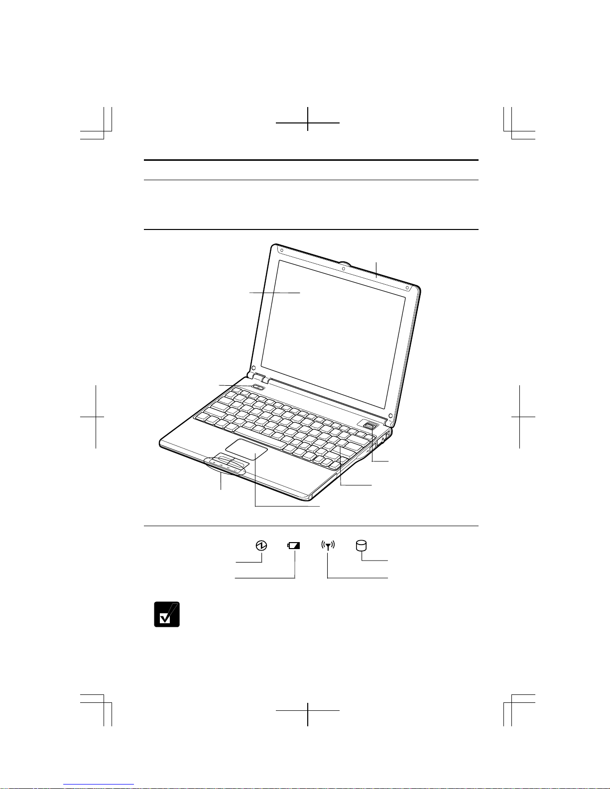
Overview of Computer
Each number after an arrow indicates the page referring to the part. Actual
appearance of your computer may be slightly different depending on the model.
Front
LCD Screen
→2-8
Power Button
→1-5
Wireless LAN Antenna
→5-4
Mobile Mode Switch
→3-12
Status Indicators
→below
Glide Pad →2-4
Keyboard →2-6
Status Indicators
Power Indicato
Battery Indicato
Hard Disk Indicator
ntenna Indicator
Never turn off the computer when the hard disk indicator is on. This may
damage the data on the hard disk.
xxi
Page 22

Right
AC Adapter Jack→1-4
PC Card Slot→4-17
Left
Headphone/Audio Output Jack →4-14
Connection Cradle Port
→7-5
Rear
External MonitorPort →4-12
USB Port
→4-3,7,16,21
USB port→4-3,7,16, 21
LAN Jack →5-2
xxii
Page 23
→2-3
V
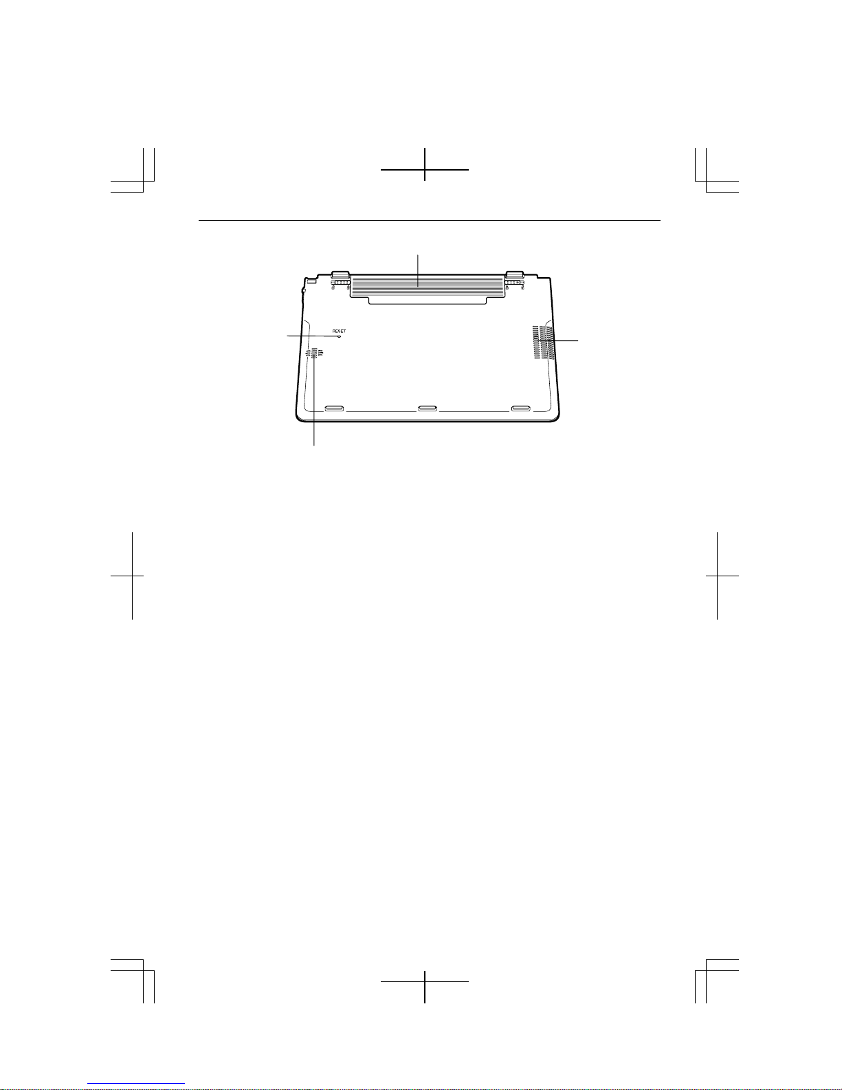
Bottom
Battery Pack→3-1
Reset Switch
entilation
Openings→ iv
Speaker
xxiii
Page 24

xxiv
Page 25
CHAPTER 1
Quick Setup
Your computer is designed and pre-configured for easy setup and use. This chapter
describes the steps to set up your computer and operate it as quickly as possible. Read
this chapter first.
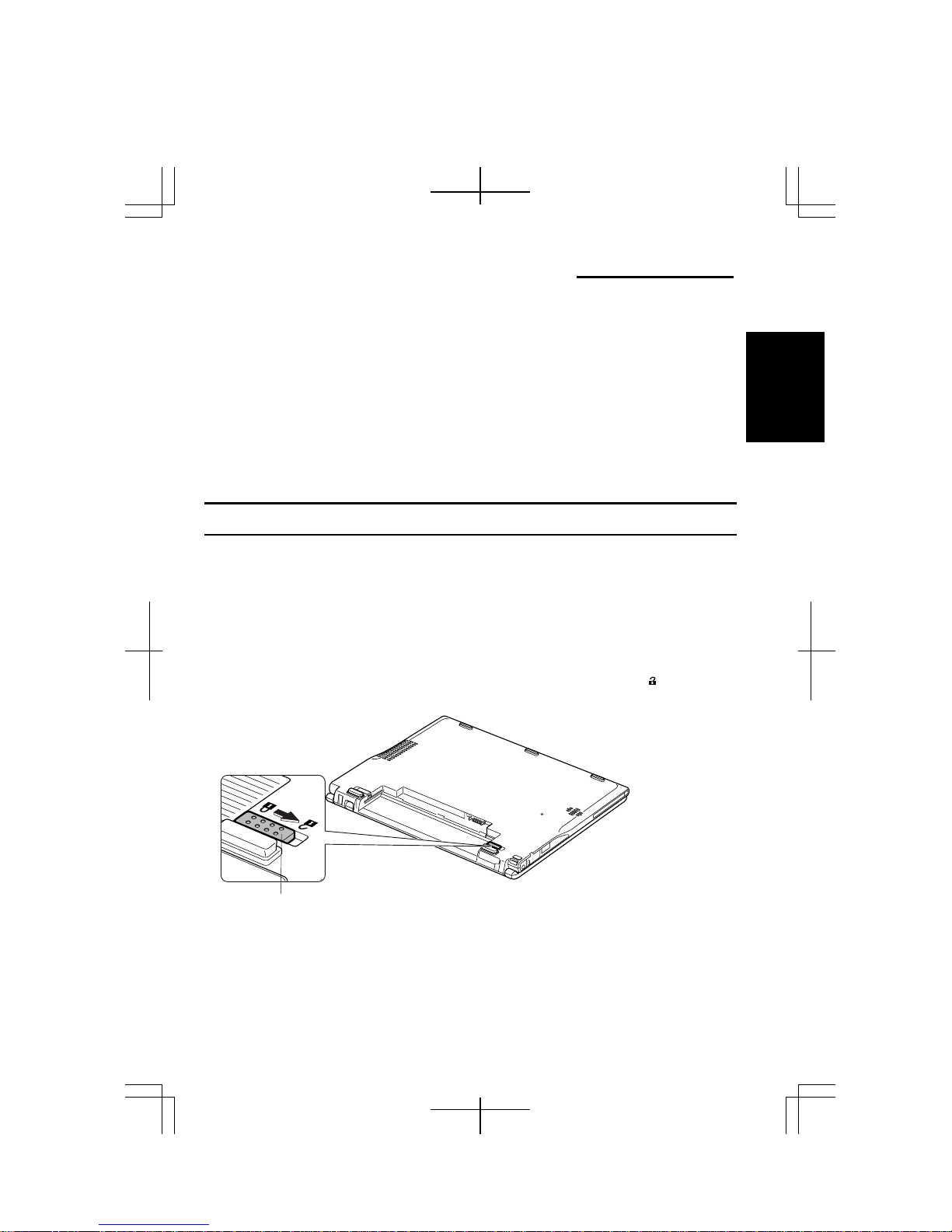
Installing Battery Pack
Your computer is powered with either the battery pack or AC power source. See the
next chapter for more information on the power sources. Before using your computer
for the first time:
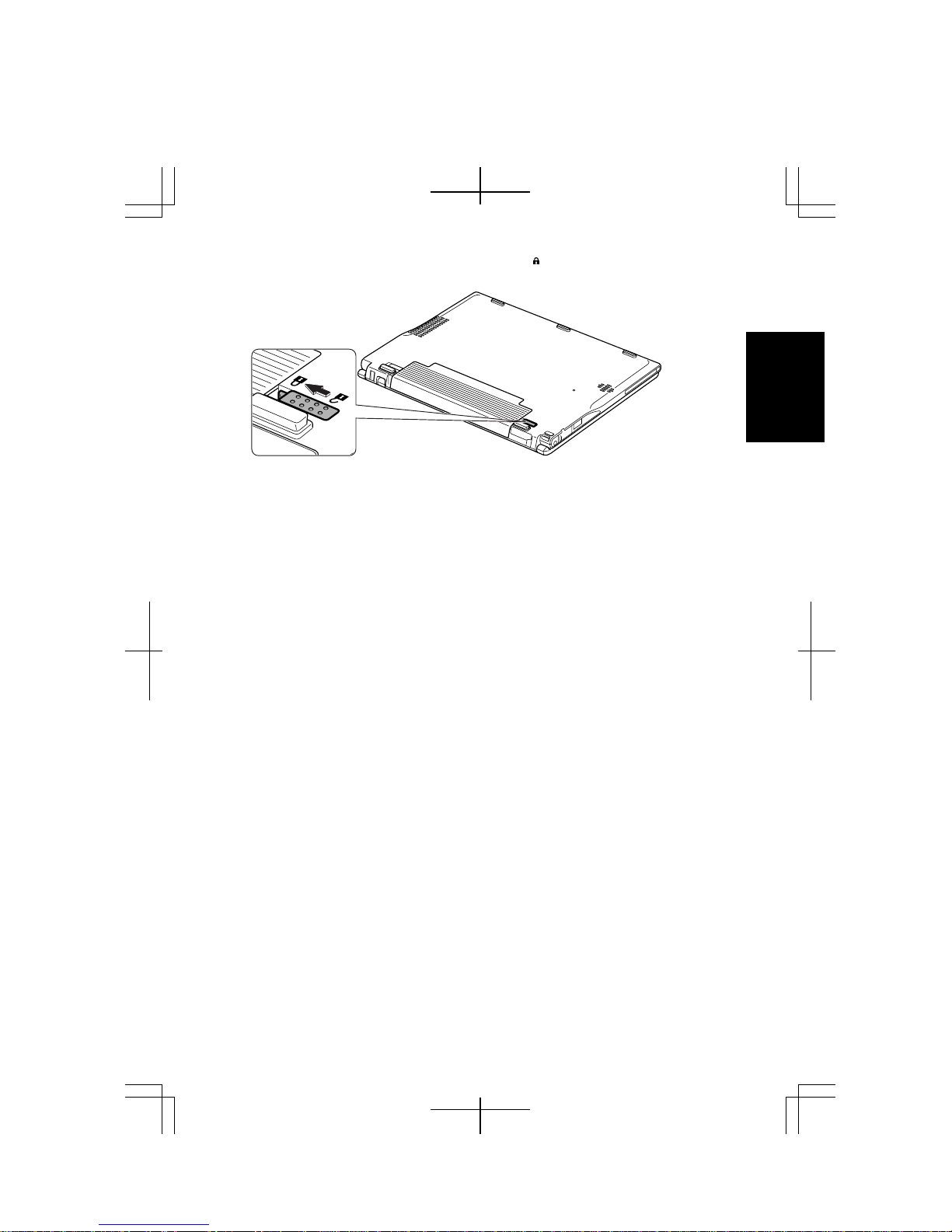
1. Place your computer upside down.
2. Slide the battery stopper of your computer to the unlocked position(
).
1
Battery Stopper
1-1
Page 26
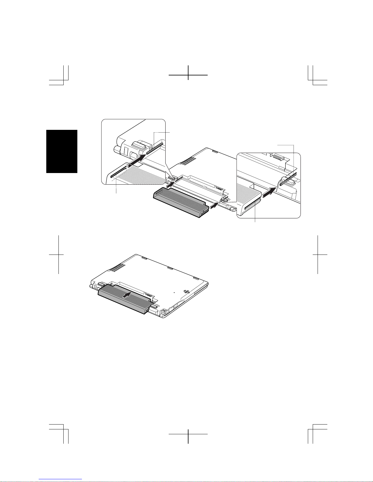
3. Insert the battery pack into your computer by matching the notched parts of the
battery to the projected parts of your computer.
Projected Part
Projected Part
1
Notched Part
4. Push the battery pack all the way until you hear the clicking sound.
Notched Part
1-2
Page 27
5. Slide the battery stopper to the locked position ( ).
1
6. Turn your computer over and go to the next section.
1-3
Page 28
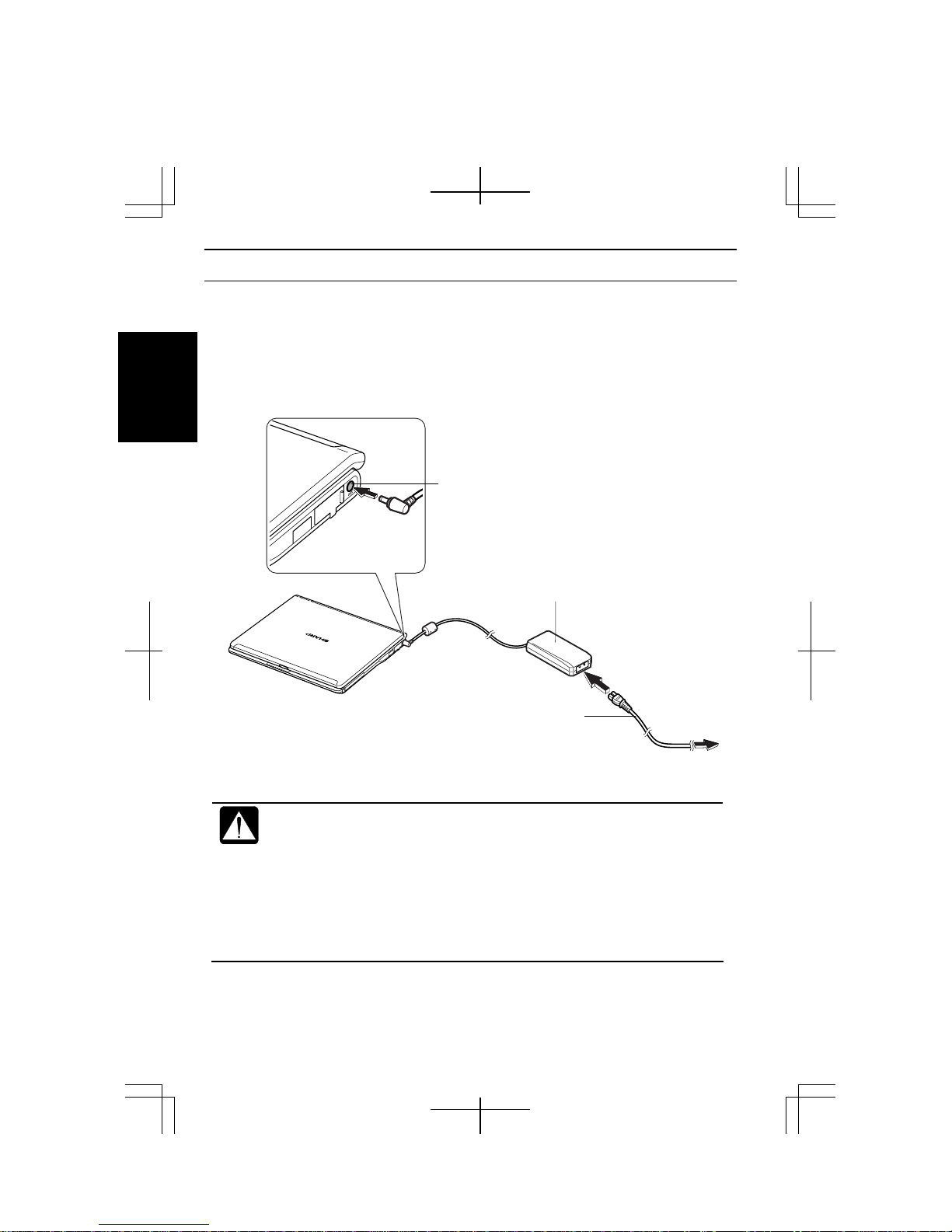
Connecting to AC Power Source
1. Plug the AC adapter cable into the AC adapter jack on the right side of your
computer.
2. Plug the AC power cord into the AC adapter.
3. Plug the AC power cord into a wall outlet.
1
AC Adapter Jack
AC Adapter
1-4
AC Power Cord
• Always use the AC adapter and the AC power cord included with your
computer or the optional one (may not be available in some countries).
Using other AC adapters and AC power cords may damage your
computer.
• Always hold the AC power cord by its plug when removing it from the
wall outlet. Never pull on the cord.
• When using your computer for the first time, be sure to operate it on
AC power. If on battery power instead, you may not be able to
complete the Windows setup if the battery does not have enough power.
To Wall
Outlet
Page 29
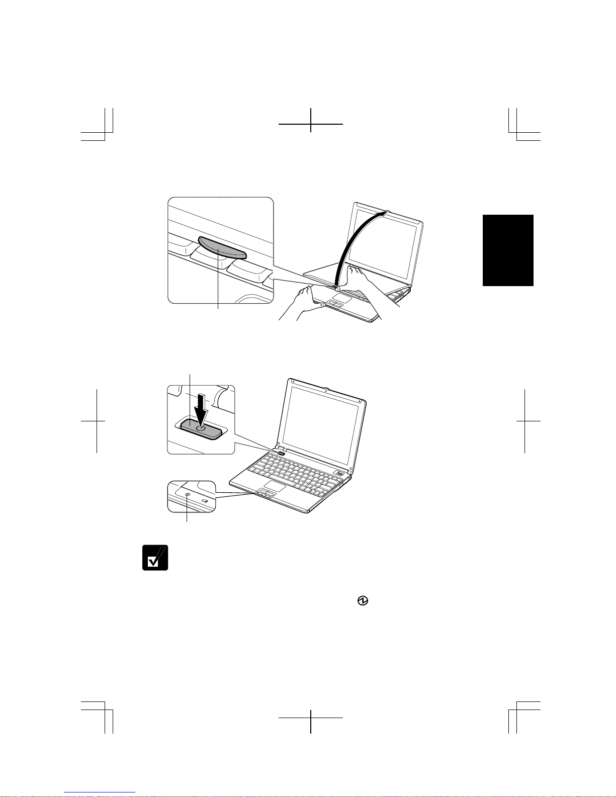
4. Steady the base cabinet of your computer with your hand and hold the jutted part
with your thumb or finger and then, raise the display.
1
Jutted Part
5. Press the power button to turn on your computer.
Power Button
Power Indicator
Do not touch or operate the keyboard and mouse until Windows
completely activates unless you are prompted to do. Otherwise, Window
may not start properly.
When you turn on your computer, the power indicator ( ) turns green, your
computer goes through a self test to detect any problems, and Windows setup process
starts. See the next page.
1-5
Page 30
Setting Up Windows
The steps in the setup process are as follows:
• Configuring your location, language and keyboard type
• Configuring your time zone
1
• Accepting license agreement
• Naming your computer
• Creating an account
• Completing configuration
To setup Windows, follow the instructions on the screen. See also the Windows
manual. It takes approximately 10-15 minutes to complete the entire setup process.
• Do not turn off your computer until completing Windows setup. If you
turn it off, you cannot set up Windows later.
• Be sure to connect your computer to AC power source. An
undercharged battery may not be able to complete the Windows setup.
• Do not connect any peripheral devices to your computer until
Windows setup completes. Otherwise your computer may malfunction.
• If the display turns off, some power management may function. In this
case, press any key to resume your computer from the power
management.
• If you cannot operate the keyboard or the touch pad, press the power
button for more than four seconds to turn off your computer. Be sure
that the power indicator turns off; then, after more than 10 seconds,
press the power button to turn it on again.
After completing Windows setup:
• Confirm Time Zone is correctly selected and set the date and time by double-
clicking the time appearing on the right of the taskbar to open Date and Time
Properties dialog box
• Press Fn+F1 ( ) keys to activate the integrated antenna for Wireless LAN
communication.
1-6
Page 31

Properties Dialog Box in Windows
In this manual, you will often see the expression “XXX Properties dialog box.” A
dialog box is a window containing text boxes, check boxes, buttons, etc., with which
you can send commands to Windows or other application programs. To open the
properties dialog boxes, click start - Control Panel. The Control Panel has two types
of views: Category view and Classic view. The Category view allows you to choose
the category that may be related to what you want to do, then, choose the task by
clicking it. The Classic view gives you the icons representing their components or
features. Double-click one of the icons to open their dialog box or windows. Some of
the dialog boxes you will use often are:
• Display
• Phone and Modem Options
• Mouse
• Power Options
• System
Clicking Switch to XXX View string appearing at the upper left of the
Control Panel window allows you to toggle between the two views.
1
1-7
Page 32

Turning Off Your Computer
When you’ve finished using your computer, turn it off with one of the following ways:
• From the start menu
1. Click start – Turn Off Computer.
2. In the Turn off computer dialog box, click Turn Off.
1
• With the power button
Before using this step, confirm that Shut down is selected in When I press the power
button on my computer in Advanced tab of Power Options Properties dialog box.
Close the cover to keep the screen and keyboard clean and protected.
If you have not saved a file, a dialog box will appear asking whether you
want to save it.
• Do not turn off or reset your computer while the hard disk indicator or
the indicator on the optional external floppy disk drive unit or the
external CD-ROM drive unit is lit. Doing so may damage or even wipe
out the data.
• Before turning it back on, wait at least ten seconds after turning off
your computer. Turning the power off and on in rapid succession can
damage your computer’s electrical circuitry.
1-8
Page 33

CHAPTER 2
Basic Operations
This chapter describes the basic operations of your computer.
Choosing Power Source
You can use your computer with one of the following power sources:
• AC power from a wall outlet
Use AC power whenever possible; rely on the battery only when AC power is not
available.
• Rechargeable battery
Your computer is equipped with a standard battery pack. You can also use an
optional high capacity battery. See Chapter 3 for the battery information.
About Power Indicators
The following indicators show the power status of your computer.
Indicator Light Meaning
Power
Battery
The battery indicator is always off when your computer is turned off and not
connected to AC power source.
On (green) Operating
Blinking (green) In System Standby
Off Powered off or in System Hibernate
Connected to AC
Power Source
Powered by
Battery
On (green) Fully charged
On (orange) Being charged
Blinking
(orange)
Off Has power
Blinking (red) Almost completely discharged
In abnormal state (Remove the
battery pack and install it again.)
(The warning beep sounds.)
2
2-1
Page 34

Using AC Adapter
When connected to a wall outlet, the AC adapter provides power for operation and
charges the battery. The AC input voltage can range from 100 to 240 volts so that you
can use your computer with the appropriate plug adapter.
2
• When the battery is hot, the battery indicator may turn off and stay off
until the battery becomes cool.
• For more information on System standby/hibernate, see Chapter 3.
The AC power cord included with your computer is appropriate for the
voltage used in the area in which you purchased your computer. If you
attempt to connect your computer to a wall outlet other than in this area,
check the voltage of the outlet and use an AC power cord appropriate for
the outlet. Consult local service staff if you are not sure.
2-2
Page 35

RESET
Resetting System
You may need to restart the system if your computer hangs up or a new hardware or
software is installed. When a message appears after the installation, click OK, Yes, etc.
to restart Windows.
You can also restart Windows by clicking start - Turn Off Computer; then, Restart.
Resetting may cause data loss. Use the resetting process only if the
normal Windows Shut Down does not work because of software
malfunction. Although resetting will not damage the system, you may
lose the data you are processing.
Warm Boot (Software Reset)
If the system is locked up because of a software problem, you can reset or reboot the
system by pressing the Ctrl+Alt+Del keys simultaneously and select Applications tab
of Windows Task Manager dialog box. Click the program name which hangs up, then,
End Task. If this does not solve the problem, click Disconnect or Logoff of Windows
Task Manager dialog box, then Yes.
Power Switch
You can turn off your computer with the power button if you encounter hardware or
software problems which lock up the system. In this case, press the power button for
more than four seconds.
Reset Switch
If you cannot turn off your computer by pressing the power button, you can use the
reset switch on the bottom of your computer. To reset the system, insert a narrow
object into the small hole to press the switch.
2
Reset Switch
RESET
2-3
Page 36

Using Glide Pad
Your computer is equipped with an integrated pointing device called glide pad. Using
the glide pad, you can move the pointer, select an item from a menu, and perform other
tasks in the same way you would with a mouse.
2
Glide Pad
• Do not hit or scratch the surface of the glide pad with pointed objects
(such as a ballpoint pen).
• Do not operate the glide pad with a moist finger. This may cause the
glide pad to operate incorrectly.
Enabling Glide Pad
When a USB mouse is connected to one of the USB ports of your computer, the glide
pad is disabled, which means that your computer does not respond to any tapping on
the pad. Therefore, confliction with the mouse and/or unexpected move of the pointer
on the screen can be avoided.
To enable the glide pad, use one of the following ways.
• Disconnect the connected USB mouse. (No mouse must be connected.)
• With a USB mouse connected, open Mouse Properties dialog box, click Device
Settings tab, then, Enable button. (This operation allows your computer to always
respond to the glide pad, while the connected USB mouse also works.)
When the glide pad is disabled, the Touch Pad icon ( ) on the taskbar is
crossed ( ).
2-4
Page 37

Using Glide Pad
Take a moment to become familiar with how the glide pad works.
Place Your Fingertip
Place your left or right hand next to the glide pad, resting your wrist naturally in a
relaxed manner. Place your thumb or finger on the glide pad.
Move Your Fingertip
The rectangular pad of the glide pad is used to move the pointer around the display.
As you slide your fingertip across the pad, the pointer on the screen moves in the same
direction across the screen. The glide pad is very sensitive, so you do not have to exert
much pressure on the pad. The glide pad will respond to a light touch from your
fingertip.
Click, Double-click, and Right-click
To click or double-click, you can use the left button just like that of a mouse. Instead
of clicking the left button, you can also just tap gently anywhere on the rectangular
pad. For right-clicking, you must use the right button.
If the interval between clicks is too long, the double-click will not
function.
Drag and Drop
You can move the items by using “drag and drop” below:
1. Position the pointer over the item you wish to move.
2. Press the left button; do not release it.
3. Move the pointer while holding the left button. The item moves together with the
pointer.
4. Release the button when the item reaches its destination.
Or you can tap the pad twice and hold it instead of pressing the left button in the
step 2.
Scroll
You can scroll through information in a list or in a document by using the glide pad.
To view information vertically, place your finger on the most right part of the glide
pad and slide your finger up and down. To view horizontally, place your finger on the
bottom part of the glide pad and slide your finger to the left or the right. This
procedure works only in limited applications.
2
2-5
Page 38

Changing Configuration
In the Mouse Properties dialog box, you can change the configuration of the glide
pad, such as swapping left and right buttons, changing the pointer size, etc. Double-
icon on the taskbar.
click
2
2-6
Page 39

Using Keyboard
Your computer, equipped with the Windows Enhanced Keyboard, provides all the
functionality of a full-sized desktop keyboard.
Special Keys
Windows Key ( )
Application Key ( )
System Function Keys
Your keyboard contains the function keys labeled F1 through F12 for special actions.
Use them in conjunction with Fn key.
Fn + F1 (
Fn + F3 (
Fn + F4 (
Fn + F5 (
Fn + F6 (
)
)
)
)
)
Fn + F7 ( )
Fn + F11 ( )
Fn + F12 (
)
Opens the Windows start menu. This key functions the
same as the start button on the screen.
Opens short-cut menus for the specific items. This key
functions the same as the right mouse button.
Turns the wireless LAN antenna on and off.
Decreases the audio volume.
Increases the audio volume.
Rotates display mode between LCD only, an external monitor
only, and both (when connecting an external monitor).
Decreases the LCD screen brightness.
Increases the LCD screen brightness.
Turns the LCD screen on and off.
Forces your computer into System standby, hibernate, or
powered off. See Power Management of Chapter 3 for more
information.
2
2-7
Page 40

Controlling Volume
You can adjust the output volume of your computer with the following volume
controls which interact with each other.
With Keyboard
To decrease the output volume, press and hold Fn key and then, press F3 (
To increase the output volume, press and hold Fn key and then, press F4 (
2
These functions can work on Windows.
On Windows
1. Click start - Control Panel.
2. Click Sounds, Speech, and Audio Devices; then, Sounds and Audio Devices. If
Classic view is selected, double-click Sounds and Audio Devices icon.
3. In Sounds and Audio Devices Properties dialog box, slide the lever to control the
output volume.
4. Click OK and close the dialog box; then the Control Panel window.
You can also easily adjust the volume in the window that will open when
clicking the speaker symbol on the taskbar. When the symbol is not on the
taskbar, check the box of Place volume icon in the taskbar in the step 3.
If you want to adjust the output volume of each source individually:
1. Click start - Control Panel.
2. Click Sounds, Speech, and Audio Devices; then, Sounds and Audio Devices. If
Classic view is selected, double-click Sounds and Audio Devices icon.
3. In Sounds and Audio Devices Properties dialog box, click Advanced… button of
Device volume section.
4. Slide the lever of the source that you want to control.
5. Close the dialog box, then; click OK and close the Control Panel window.
) key.
) key.
2-8
Page 41

If you control:
Wave Controlling the volume of CD or WAVE file
SW Synth Controlling the volume of MIDI file
Any software containing audio function may also have its own volume
control. Note that the volume controls discussed on the previous page
and the software volume control will interact with each other.
2
2-9
Page 42

Adjusting Display
You can adjust the brightness, resolution, and number of colors of the internal LCD
display for more comfortable viewing.
Changing Brightness of Display
To decrease the brightness of the internal LCD display, press and hold the Fn key, and
then press the F6 (
2
To increase the brightness of the internal LCD display, press and hold the Fn, and then
press the F7 (
Changing Resolution and Number of Colors
When shipped, your computer is set to the default resolution and color. The default
resolution is 1024 x 768 at 64K colors. To change the resolution and the number of
colors, follow the instructions below:
1. In the Display Properties dialog box, select Settings tab.
2. Select the number of the colors in the Color quality, and select the resolution in
the Screen resolution. Refer to the table below.
3. Click OK; then, Yes.
Available Resolutions and Colors
Resolution
800 x 600 64K
1024 x 768 64K
1280 x 768 64K
1280 x 1024
1600 x 1200 64K
(*1) )
(*2)
a Dithering algorithm.
2048 x 1536 64K
Only 1024 x 768 dots appear even on the internal LCD screen of 1280 x 768 or
higher resolution. To see the hidden parts, move the mouse pointer to the parts and
scroll it. When the resolution is set to 1024 x 768 or higher, the number of colors
may be automatically set to 64K.
On the internal LCD screen, the number of colors in this mode is made using
) key.
(*1)
) key.
Number of Colors
16M
16M
16M
64K
16M
(*2)
(*2)
(*2)
2-10
Page 43

• You cannot switch to display resolutions and number of colors that are not
available.
• In the Color quality, Medium (16 bit) means 65,536 (64K) colors, and
Highest (32 bit) means about 16,770,000 (16M) colors.
Displaying on Screen Upside Down
This feature allows you to show the images on the LCD screen upside down. Use this
feature when showing the images on your computer to someone on your opposite side.
To display the image upside down, press Ctrl+Shift+F4 (
To display the image in its original position, press Ctrl+Shift+F3 (
• When displaying images upside down, you see the pointer on the screen
move in the opposite direction. Moving your finger or the mouse to the
right on the glide pad, for example, will make the mouse pointer move
to the left.
• When displaying images upside down, drawing speed may be delayed.
• Do not display upside down when playing animation..
).
).
Changing Wallpaper and Setting Screen Saver
You can enjoy various desktop patterns or screen savers.
Changing Wallpaper
1. In the Display Properties dialog box, select Desktop tab.
2. Select appropriate wallpaper in Background.
3. Click OK.
Setting Screen Saver
1. In the Display Properties dialog box, select Screen Saver tab.
2. Select an appropriate screen saver in Screen saver and set time when screen
saver starts.
3. Click OK.
To disable the screen saver, select [None] from the Screen saver pull-
down menu.
2
2-11
Page 44

Sharing Your Computer
If you are sharing your computer with your colleagues or family members, set a user
account for each person. Every user can choose their favorite desktop setting, web site
lists, or make their own My Documents folder etc., and save them to their user
accounts. When you turn on your computer, select your user account.
Setting New User Account
2
1. Click start - Control Panel.
2. Click User Accounts. If Classic view is selected, double-click User Accounts
icon.
3. Click Create a new account string.
4. Type a name for the new account and click Next.
5. Select the account type; then, click Create Account. If you have selected a
Limited account, then that user account has limits for using your computer. See
Help and Support Center in start menu for more details.
6. Close User Accounts dialog box; then, the Control Panel.
If more than one user accounts are set to your computer, you must select which user
account you will log in when you turn on your computer.
Log Off Your Computer
“Log off” is useful because you do not have to turn off your computer when you finish
your task and pass your computer to another person. There are two ways to log off
your computer, Switch User or Log Off.
If you select Switch User, you can pass your computer to another person without
closing your current applications. For example, if you are viewing a Web site, and
your colleague needs to open a program on your computer, use Switch User. You can
then view the same Web site by just switching users after your colleague finishes with
your computer.
If you select Log Off, the system will close all your session and you need to save your
files before logging off your computer.
1. Click start - Log Off.
2. Select Switch User or Log Off. If you select Log Off, the dialog box, which asks
you to save your data may appear.
2-12
Page 45

3. Select a new account to start Windows XP again.
If you cannot see Switch User in Log Off Windows dialog box, click
Change the way users log on or off string in User Accounts dialog box,
and check Use Fast User Switching and click Apply Options.
Setting Password to User Account
You can set a password to each user account to avoid unauthorized use of your
computer. Once you set the password, you need to enter it when you log on to its
account. You cannot start your computer with the user account if its password is not
correct, so unnecessary password setting can cause trouble in starting the system.
Setting Password
1. Click start - Control Panel.
2. Click User Accounts. If Classic view is selected, double-click User Accounts
icon.
3. Select the account you want to set a password to. You will only have this option
if you log onto the computer as a member of the Computer administrators group.
If you log on your computer with a limited user account, go to the next step.
(You cannot set a password to another user account.)
4. Select Create a password string.
• If the password has been already set, Create a password will not
appear.
• Only the members of the Computer administrators group can set a
password to another user account.
5. Type a new password.
6. Type the new password again to confirm it.
7. If necessary, type a password hints word to remember the password you set.
8. Click Create Password.
9. Close the User Accounts dialog box; then, the Control Panel window.
Changing Password
1. Follow the steps 1-2 on the previous section.
2. Select the account you want to change, if you log on to your computer as a
member of the Computer administrators group. If you log on your computer with
2
2-13
Page 46

2
a limited account, go to the next step. (You cannot change the password of
another user account.)
3. Select Change the password string or Change my password string.
• If the password has not been set yet, Change the password or Change
my password will not appear.
• Only the members of the Computer administrators group can change
the password of another user account.
4. Type the current password. If you are changing another user’s password, skip this
step.
5. Type a new password.
6. Type the new password again to confirm it.
7. If necessary, type a password hints word to remember the password you set.
8. Click Change Password.
9. Close the User Accounts dialog box; then, the Control Panel window.
Deleting Password
1. Follow the steps 1-2 on Setting Password.
2. Select the account you want to delete its password, if you log on to your
computer as a member of the Computer administrators group. If you log on your
computer with a limited account, go to the next step. (You cannot delete the
password of another user account.)
3. Select Remove the password string or Remove my password string.
• If the password has not been set yet, Remove the password or Remove
my password will not appear.
• Only the members of the Computer administrators group can delete the
password of another user account.
4. Type your password and click Remove Password. If you log on to your computer
as a member of the Computer administrators group and want to delete the
password of another user account, just click Remove Password.
5. Close the User Accounts dialog box; then, the Control Panel window.
2-14
Page 47

CHAPTER 3
Battery and Power Management
This chapter explains how to manage your computer’s power effectively and use the
battery pack.
In this section, you often see the expression “Power Options Properties
dialog box”. To open the dialog box:
1. Click start - Control Panel.
2. Click Performance and Maintenance - Power Options in
Category view or double-click Power Options icon in Classic view.
Battery Pack
When not connected to an external power source, your computer operates with the
rechargeable battery pack. The duration of the battery life may be longer if your
computer’s power management is active. See the next section for power management.
To keep the battery life longer:
• Condition the battery pack if the actual remaining power in your battery is less than
what Windows Power Meter indicates. (See Conditioning Battery Pack section in
this chapter.)
3
• Turn off your computer when you are not using it.
• The duration of the battery depends on your computer usage. Using
applications, which heavily use external peripherals, will result in
shorter battery life.
• When using your computer for several hours with battery power,
enable power management and set System hibernate. Refer to the
Power Management section in this chapter.
• When the battery has not been charged, your computer may not operate
properly. Connect the AC power source to charge the battery.
3-1
Page 48

Charging Battery Pack
1. Connect the AC adapter to your computer. While the battery is being charged, the
battery indicator lights orange.
2. When the battery is fully charged, the battery indicator turns green. Charging
time may vary according to the status of your computer.
• The battery indicator may turn off even while the battery is being
charged. This is because the battery pack is hot, and the charging
stops temporarily. When the battery becomes cool, the charging will
start and the battery indicator will turn on again.
• The battery pack may not be installed correctly if the battery indicator
blinks orange. In this case, turn off your computer, remove the AC
adapter and the battery pack; then, install the battery pack and connect
3
the AC adapter again. If the battery indicator still blinks orange, ask
your local dealer for assistance.
• When the battery pack is hot (for example, after a long use), it may
take longer to be fully charged.
Charging Battery Pack Using Connection Cradle
You can also charge the battery pack using the connection cradle. Insert the battery
pack in your computer, set your computer in the connection cradle and connect it to
the AC power. For details on connection cradle, see Chapter 7.
Checking Battery Level
On Windows
You can check the battery level by placing the pointer on the battery icon
( : powered on battery) or AC plug icon ( : powered on AC power and charging
the battery pack) on the taskbar, or double-clicking one of these icons ( , or
: powered on AC power) to open the Power Meter dialog box. If the battery is fully
charged, remaining capacity level will not appear even if you point to the icon.
If you cannot see the battery or AC plug icon, follow these instructions:
1. In the Power Options Properties dialog box, select Advanced tab.
2. Check the box of Always show icon on the taskbar and click OK.
3. Close the Control Panel window.
3-2
Page 49

• The remaining operating time depends on the amount of the power you
are consuming. If you are using the audio system, PC card slot, hard
disk drive, or peripheral devices with your computer, it may consume
more battery power.
• If the actual remaining power in your battery is less than what Power
Meter indicates, you should condition the battery pack as per the
procedure on Conditioning Battery Pack section in this chapter.
With Battery Level Lamp
You can also check the battery level by the battery lamp on the battery pack.
Remove the battery pack from your computer and push the battery level button on the
battery pack.
Battery Level Lamp
3
Battery Level Button
Low Battery Indication
When the battery power level becomes significantly low, the battery indicator ( )
blinks red, the warning beep sounds. Save your data and turn off your computer, or
connect the AC power source immediately. Otherwise, your computer will be shut
down and the unsaved data may be lost.
Battery Indicator
3-3
Page 50

On Windows, you can set the battery level for sounding an alarm and letting your
computer go on System standby, System hibernate or shut down afterward.
1. In the Power Options Properties dialog box, select Alarms tab.
2. Set the battery level at which the alarms are activated. We recommend you set
Critical battery alarm to 5 % or more and Low battery alarm to more than the
value of Critical battery alarm.
3. Set the Alarm Action… to the appropriate settings.
4. Click OK twice.
5. Close the Control Panel window.
Conditioning Battery Pack
3
When the actual remaining power in your battery is less than what Windows Power
Meter indicates, you need to condition the battery pack or buy an optional high
capacity battery pack.
1. Make sure your computer is turned off. Connect the computer to AC power
source and wait until the battery is fully charged. The battery indicator turns
orange first, then, turns to green when the battery pack is fully charged.
2. Turn on your computer.
3. When the message Press <F2> for System Utilities appears, press F2 to open the
Setup Utility.
4. Disconnect the AC adapter.
5. Set the mobile mode switch to the NORMAL position.
3-4
Mobile Mode Switch
Mobile Mode Normal Mode
Page 51

6. With the Fn key pressed down, press the F7 key several times so that the screen
brightness is maximized.
7. Leave your computer on to discharge the battery pack. When it is completely
discharged, the system will automatically shut down.
8. Connect your computer to AC power source and let the battery fully charged
again.
• Do not turn on your computer while charging the battery pack.
• Do not connect your computer to a wall outlet while discharging the
battery. The conditioning will be cancelled.
Repeated charging and discharging or long-term storage of the battery
pack cause battery deterioration. In this case, replace the battery pack
with a high capacity battery pack.
3
3-5
Page 52

Changing Battery Pack to Optional High Capacity Battery Pack
The capacity of a battery pack gradually decreases when used repeatedly (the
deterioration rate depends on the operating environment). If the battery life becomes
extremely short even after the conditioning, you should buy an optional high capacity
battery pack (CE-BL25).
When you replace the battery pack with the optional one:
1. Turn off your computer and disconnect the AC adapter from your computer.
2. Close the display cover and turn over your computer on a flat place.
3. Slide the battery stopper to the unlocked position (
).
3
Battery Stopper
4. Slide the battery release lever to the unlocked position (
pull out the battery pack (2).
) and hold it (1); then,
3-6
Battery Release Lever
Page 53

5. Insert the high capacity battery pack into the computer by matching the notched
parts of the battery to the projected parts of the computer.
High Capacity Battery Pack
(CE-BL25)
Notched Part
Checking Battery Level of High Capacity Battery Pack
Follow the steps in Checking Battery Level in this chapter.
Conditioning High Capacity Battery Pack
Follow the steps in Conditioning Battery Pack in this chapter.
3
3-7
Page 54

Power Management
Power management saves electricity and extends battery life by controlling power
supply to built-in devices. You can set the following power management properties on
Windows.
• Stopping power supply to the hard disk
• Stopping power supply to the display
• Using System standby/hibernate
• Using mobile mode switch
3
To open Power Options Properties dialog box, click start – Control Panel, and click
Performance and Maintenance; then, Power Options. If Classic view is selected,
double-click Power Options icon.
Note that the power management may not seem to function when you are
using an application program that accesses the hard disk periodically.
Stopping Power Supply to Hard Disk
1. In the Power Options Properties dialog box, select Power Schemes tab.
2. Set Turn off hard disks to an appropriate value, and click OK.
3. Close the Control Panel window.
Stopping Power Supply to the Display
This procedure is also effective for an attached external monitor complying
with power management.
1. In the Power Options Properties dialog box, select Power Schemes tab.
2. Set Turn off monitor to an appropriate value, and click OK.
3. Close the Control Panel window.
3-8
Page 55

Using System Standby/Hibernate
System standby/hibernate is a very useful power management tool. For example, after
your computer has entered System standby mode, you can restart your computer more
quickly when compared to a restart, after a normal shutdown operation. When your
computer resumes from System standby/hibernate, the system restores the exact last
state of your computer. In Windows, you can define System standby or System
hibernate the system enters under what conditions.
• System standby stores the current condition of your computer in RAM and stops
power supply to all but a few essential components. Your system enters and
resumes from System standby per the conditions mentioned later. In System standby,
the power indicator blinks green. To resume from System standby, press any key.
• System hibernate saves the current condition of your computer in part of the hard
disk and turns off your computer. Your system enters and resumes from System
hibernate per the conditions mentioned later. In System hibernate, the power
indicator is off. To resume from System hibernate, press the power button.
When entering/resuming from System standby/hibernate, follow these
instructions:
• Finish communications, printing, and playing music or video before
entering System standby/hibernate.
• Do not operate your computer or peripheral devices, or
connect/disconnect peripheral devices, while entering/resuming from
System standby/hibernate.
• Save your data before your computer enters System standby. If the
power supply to your computer is stopped, the RAM contents will be
lost.
• Select your user account if Windows requires when your computer
resumes from System standby/hibernate.
3
3-9
Page 56

Supporting System Hibernate
If your battery becomes completely discharged during System standby,
you will lose unsaved data and will need to reboot your computer.
Therefore, if you are planning to leave your computer powered by battery
for long periods of time, we recommend System hibernate.
Confirm that System hibernate is supported with the following steps.
1. In the Power Options Properties dialog box, select Hibernate tab.
2. Confirm Enable hibernation is checked.
3. Click OK.
4. Close the Control Panel window.
3
Set Timer to Enter System Standby/Hibernate Automatically
Your computer will enter System standby/hibernate automatically when the specified
time has passed without any operation. To set the time:
1. In the Power Options Properties dialog box, select Power Schemes tab.
2. From the pull-down menu of System standby or/and System hibernates, select the
elapsed time before your computer automatically enter System standby/hibernate.
3. Click OK.
4. Close the Control Panel window.
Entering System Standby/Hibernate
Your computer enters System standby/hibernate in each of the following cases:
• You select Stand By or Hibernate (which will replace Stand By if you press Shift
key) in the Turn off computer dialog box. To open the dialog box, click start – Turn
Off Computer.
• The specified time in System standby or System hibernates in Power Schemes tab of
Power Options Properties dialog box has passed without any operation (See the
previous section).
• The screen cover is closed.
The above functions if you perform the following:
1. In the Power Options Properties dialog box, select Advanced tab.
2. Select Hibernate or Stand by in When I close the lid of my portable computer
field.
3. Click OK.
4. Close the Control Panel window.
3-10
Page 57

• You press the power button.
The above functions if you perform the following:
1. In the Power Options Properties dialog box, select Advanced tab.
2. Select Hibernate or Stand by in When I press the power button on my
computer field.
3. Click OK.
4. Close the Control Panel window.
• You press Fn+F12 ( ).
The above functions if you perform the following:
1. In the Power Options Properties dialog box, select Advanced tab.
2. Select Hibernate or Stand by in When I press the sleep button on my computer
field.
3. Click OK.
4. Close the Control Panel window.
If Ask me what to do is selected in the step 2 of You press the power
button or You press Fn+F12 ( ), the Turn off computer dialog box will
appear when you press the power button or Fn+F12 ( ) key
combination. You can select System standby or System hibernate at that
timing.
• The battery level is low.
The above functions if you set the alarm in Windows. See Low Battery Indication
in this chapter.
Disabling Power Management
1. In the Power Options Properties dialog box, select Power Schemes tab.
2. Set Turn off monitor, Turn off hard disks, System standby, and System hibernates
to Never; then, click OK.
3. Close the Control Panel window.
3
3-11
Page 58

Using Mobile Mode Switch
Your computer is equipped with the mobile mode switch allowing you to extend
battery life. When your computer is in mobile mode, it automatically controls system
power consumption: by reducing CPU performance and decreasing screen brightness.
The control will make the battery life longer.
Mobile Mode Switch
3
Mobile Mode
Normal Mode
Mobile Mode
Use your computer in mobile mode to obtain longer battery life when needed. The
mobile mode provides the second lowest screen brightness.
Normal Mode
Use your computer in normal mode when you do not need to power down CPU
performance even on battery operation.
• The mobile switch does not work when your computer is powered by
the AC power source.
• The screen brightness can be increased by pressing the F7 key while
holding down the Fn key. Be sure that screen brightness and battery
life are in inverse proportion to one another. The maximized screen
brightness will cause shorter battery life.
• The screen brightness can be adjusted respectively in mobile mode and
normal mode.
• Mobile mode may cause an animation to produce an irregular motion
or frame dropouts since the CPU performance is reduced.
3-12
Page 59

CHAPTER 4
Peripherals
This chapter describes how to use peripheral devices with your computer. You can
connect a floppy disk drive unit, an optional CD-ROM drive unit, a printer, an external
monitor, an, PC cards, or other devices to your computer. To ensure proper use, be
sure to read the instructions for each peripheral device before connecting it to your
computer.
Peripheral Device Connectors
Your computer has connectors for peripheral devices, shown on the next page. For
connection, refer to the section explaining each device, or contact your dealer.
• Be sure to turn off your computer and the peripheral devices before
connecting them (except when connecting/inserting USB devices, an
IEEE1394 device, a PC card, etc.).
• Confirm the peripheral device you will connect is Windows XP
compatible.
• When you connect some of the devices, you may have to turn on your
computer before powering on the devices.
• Some devices require that you install their drivers before use.
4
4-1
Page 60

Peripheral Connection Overview
External Monitor Port*
USB Port
Headphone/Audio Output Jack
4
USB Port
*Use the provided display converter cable to connect an external monitor to your
computer.
Connector Shape
Connector name Connector shape
USB Port
External Monitor Port
Headphone/
Audio Output Jack
4-2
Page 61

Optional External Floppy Disk Drive Unit
You can use double-density (2DD) 720KB or high-density (2HD) 1.44MB floppy
disks with the optional external floppy disk drive unit (CE-FD05).
Connecting Optional External Floppy Disk Drive Unit
• Do not place the floppy disk drive unit on its side or upside down.
• Do not press on the floppy disk drive unit. It may damage the drive or
cause malfunction.
• Do not place the AC adapter on the floppy disk drive unit. It may cause
the drive to malfunction.
Connect the floppy disk drive unit cable to either of the USB ports on your computer.
Be sure to let the USB mark side up when connecting the cable to your computer.
Optional Floppy Disk Drive
4
USB Port
USB Mark
Handling Floppy Disk
• Do not open the shutter and touch the disk inside; otherwise, you will not be able to
read or write data to the disk.
• Do not place floppy disks near magnets or heat source, in direct sunlight or in a
dusty place, etc.
• Never subject a disk to sudden shocks or extreme vibration. Do not drop, bend, or
place heavy objects on a disk.
• Do not spill liquid onto a disk.
4-3
Page 62

Inserting Floppy Disk
Hold the floppy disk with the arrow facing up, toward the drive. Slide the disk into the
drive until it locks into place.
Arrow Facing Up
Indicator
• Always insert a floppy disk straight into the floppy disk drive.
4
• When inserting the disk, make sure it is not upside down.
• Do not use excessive force when inserting the floppy disk. If you have
difficulty inserting or removing disks, seek the assistance of an
authorized service technician.
• Do not touch the disk while reading/writing data. It may cause
malfunction of your computer and the drive.
Ejecting Floppy Disk
Before ejecting the floppy disk, make sure the indicator of the floppy disk
drive unit is not lit.
Press the eject button firmly. The disk pops out slightly. Eject it and store it properly.
4-4
Eject Button
Page 63

Formatting Floppy Disk
1. Make sure the floppy disk is not write-protected, and insert it into the floppy disk
drive.
2. Click start - My Computer.
3. Right-click 3 ½ Floppy (A:) icon; then, click Format… from the pop-up menu.
4. Select the appropriate formatting options.
5. Click Start to start formatting.
• When you format a floppy disk that already contains data, all of the
data stored on the disk will be lost.
• You cannot format a double-density (2DD) 720KB floppy disk.
Removing Optional External Floppy Disk Drive Unit
To remove the unit, you need to perform the following steps before you remove it:
1. Click Safely Remove Hardware icon (
2. Click Safely remove Mitsumi USB Floppy – Drive(A:); then, Safe To Remove
Hardware dialog appears.
3. Remove the unit from your computer.
) on the taskbar.
4
4-5
Page 64

Optional External CD-ROM Drive Unit
A compact disc (CD) is a storage medium, with which you can read data, play music,
install and run programs, etc. The optional external CD-ROM drive unit (CE-CD05)
can be connected to either of the USB ports on your computer.
CAUTION FOR LASER
Use of controls or adjustments or performance of procedures other
than those specified herein may result in hazardous radiation exposure.
Maximum output and wavelength of the laser: 903µW, 785nm
CLASS1LASERPRODUCT
LASERKLASSE1
4
Precautions
• Do not disassemble the CD-ROM drive unit and do not repair it by yourself. Doing
so may cause electrical shock hazard, or a laser may damage your eyes.
Lens
• Do not store or use the CD-ROM drive unit in a dusty, humid, oily environment, or
under damp or moist conditions.
• Do not turn up the volume too high, when using the headphones.
• Do not leave the CD-ROM drive unit in direct sunlight, near a heat source or
especially in a hot automobile.
• Do not drop or jar the CD-ROM drive unit.
• Do not touch the pins/terminals of the USB cable.
• When the CD-ROM drive unit has been moved from a cold place to warm place, it
may damp or moist. Leave it for about 1 hour before using.
• Keep magnetic objects away from the CD-ROM drive unit.
• Do not insert any foreign metal object inside the CD-ROM drive unit.
• Do not touch the lens.
• If noise is heard from radio or TV, move the CD-ROM drive unit 2 m (about 6 ft.)
away from the radio or TV.
4-6
Page 65

r
Connecting Optional External CD-ROM Drive Unit (CE-CD05)
• Do not place the CD-ROM drive unit on its side or upside down.
• Do not press on the CD-ROM drive unit. It may damage the drive or
cause malfunction.
• Do not place the AC adapter on the CD-ROM drive unit. It may cause
the drive to malfunction.
1. Connect the core side connector of the USB cable included in the optional
external CD-ROM drive unit to the cable connector of the drive unit.
USB Cable
Core
2. Insert the USB connector of the cable into one of the USB ports of your
computer. The CD-ROM drive unit automatically turns on and the power
indicator lights up.
USB Port
Power Indicato
Cable Connector
4
4-7
Page 66

3. Slide the cover latch to the right and open the cover.
Cover Latch
4. Remove the protection sheet before you use the drive for the first time.
Protection Sheet
4
Handling CD
• Do not write on either side of the disk, particularly the non-label side. Data is read
from the non-label side. Do not mark this surface.
• Keep your disks away from direct sunlight, heat and excessive moisture.
• Always hold the CDs by the edges. Fingerprints, dirt or water on the CDs cause
noise or improper tracking. If a CD is dirty or does not play properly, clean it with
a soft, dry cloth, wiping straight out from the center, along the radius.
Inserting CD
You can operate the external CD-ROM drive unit only when the computer is on.
1. Make sure the busy indicator light is not on.
2. Slide the cover latch to the right to open the cover and raise it.
4-8
Busy Indicator
Page 67

3. Place your CD onto the disk spindle and press on the center of your CD with
label side up, until it locks onto the disk spindle.
L
L
A
E
B
4. Close the disk cover.
• Insert a CD firmly until it is locked onto the spindle; then, close the
disk cover, or the disk may fall off the spindle and get damaged.
• Do not leave the tray open. Also, avoid touching the lens in the tray. If
the lens becomes dirty, the CD-ROM may malfunction.
• Do not wipe the lens with materials with rough surface (such as paper
towels). Instead, use a cotton swab to gently wipe the lens.
Removing CD
1. Make sure the busy indicator is not lit.
2. Slide the cover latch to the right and open the cover.
3. Press down the disk spindle and remove the CD from the tray holding its edge.
4
• Make sure the busy indicator is not lit or blinking before opening the
disk cover.
• When opening the cover, if the CD is still spinning, wait until it has
stopped, then remove it.
4-9
Page 68

Playing CD
With some CD-ROMs, you can hear the sound of them through the audio out jack of
the CD-ROM drive unit. Connect headphones or speaker system with an amplifier to
the audio out jack.
Audio Out Jack
Disconnecting Optional External CD-ROM Drive Unit
To remove the unit, you need to perform the following steps before you remove it.
1. Click Safely Remove Hardware icon (
2. Click Safely remove USB Mass Storage Device; then, Safe To Remove Hardware
4
dialog appears.
3. Remove the USB cable from the computer.
) on the taskbar.
Mode Switches
There are the mode switches on the bottom of the CD-ROM unit.
These switches are for technical services. Keep them as a default setting, OFF.
Mode Switches
Cleaning Optional External CD-ROM Drive Unit
• Do not use solvents such as benzine, thinner, alcohol, record cleaner or anti-static
spray.
• Clean the outside of the drive with a soft, dried cloth.
• Clean the lens with a commercial lens blower if the lens is dirty.
4-10
Page 69

External Display
You can use an external monitor with your computer. To display the images on both
displays simultaneously, use the 1024x768 resolution.
• Some monitors, which are not compatible with your computer, may not
display correctly.
• In this section, you often see the expression “Display Properties dialog
box.” To open the dialog box, right-click somewhere on the Windows
desktop and select Properties from the pop-up menu.
Connecting External Monitor
Use the provided display converter cable to connect an external monitor with your
computer.
1. Turn off your computer and the external monitor.
2. Connect the provided display converter cable with the display cable as shown
below. If the display cable has screws, make sure to tighten them.
Display Converter Cable
Display Cable
4
Screw
4-11
Page 70

3. Connect one end of the display cable to the external monitor port, then, the other
end of the display cable to your external monitor. If the display cable has screws,
be sure to tighten them.
External Monitor Port
Display Cable
(supplied with the
monitor or the one
in the market)
4
4. Turn on the external monitor; then, your computer.
Disconnecting External Monitor
1. Turn off your computer and the external monitor.
2. Press the button on the connector of the display converter cable, and hold it; then,
remove it from your computer.
Button
4-12
Page 71

Switching Display
1. In the Display Properties dialog box, select Settings tab; then, click Advanced
button.
2. Select Display tab; then, click the button before the output display you desire and
click OK. Monitor means the internal LCD display and Panel means the external
display.
3. Click OK in the Confirmation window.
4. Click Yes in the Confirmation window.
5. Close the Control Panel window.
4
4-13
Page 72

Displaying Image on LCD and External Monitor
When displaying on both of the LCD monitor and the external monitor
simultaneously, the external monitor should be capable for displaying in
You can display the same image on the LCD and the external monitor simultaneously
when you connect the external monitor to your computer.
To extend the image on your LCD onto an external monitor:
1. In the Display Properties dialog box, select Settings tab.
2. Select “2”display icon, then, check the box of Extend my Windows desktop onto
this monitor at the bottom of the dialog box.
3. Click OK, then, follow the instructions shown on the screen.
4
×
768 resolution or higher. Otherwise, you may not display images
1024
on the external monitor properly.
To stop extending the image onto the external monitor, uncheck the box
of Extend my Windows desktop onto this monitor.
• You can also switch the display with Fn+F5 (
• When you log on your computer as a member of the Limited group, you
cannot switch the display with the dialog box. Use Fn+F5(
• When displaying in Resolution Expansion mode (see 6-4), you cannot
switch the display using Fn+F5 (
• While playing video or animation, you may not be able to switch the
display.
) keys.
).
) keys.
4-14
Page 73

(L)
p
g
g
Audio System
You can output sound to speakers, audio equipment or headphones.
Connecting Speaker
You can connect stereo speakers with an amplifier to the audio output jack on the left
side of your computer
Head
hone/Audio Output Jack
Stereo Mini Plu
Speakers with an Amplifier
4
Connecting Audio Equipment
You can connect analog audio equipment to the audio output jack on the left side of
your computer.
Headphone/
Audio Output Jack
Stereo Mini Plu
Analog Audio Cable
You can adjust the output volume on Windows by clicking the speaker
symbol on the taskbar or use Fn + F3 (
combination.
LINE IN
Audio Equipment
White
) or F4 (
LINE IN (R)
Red
) keys
4-15
Page 74

p
Connecting Headphone
Use the headphone with an impedance of 8Ω.or more (32Ω is recommended.)
hone/Audio Output Jack
Head
Stereo Mini Plug
4
Headphone
4-16
Page 75

USB Device
Your computer has an interface called Universal Serial Bus (USB) and its two USB
ports support USB1.1 and USB2.0. With a USB connection, you can
connect/disconnect peripherals without turning off your computer. Generally, when
you connect a device to your computer, the necessary driver will be installed
automatically. See also the manuals of peripheral devices supporting USB.
When a new device is correctly connected to your computer, the
appropriate driver is automatically installed. If the driver is not installed
correctly, you will see the message on the screen. In this case, install the
driver with the instructions on the screen.
USB Port
USB Port
To remove USB devices, you may need to perform the following instructions before
you remove them:
1. Click Safely Remove Hardware icon (
icon, click
2. Click Safely remove xxxx (xxxxx is the name of your USB device); then, Safe To
Remove Hardware dialog appears.
3. Remove the device from your computer.
to show all kinds of icons. If the icon does not appear, go to Step3.
) on the taskbar. If you cannot find the
4
4-17
Page 76

PC Card
Your computer is equipped with a PC card slot, which can accommodate a Type II
card or a CardBus compliant card. You can insert/eject the card without turning off
your computer. Before inserting a PC card into the slot, refer to its manual.
Inserting PC Card
When a new card is correctly inserted, the appropriate driver is
automatically installed. If the driver is not installed correctly, you will
see the message on the screen. In this case, install the PC card driver by
following the instructions on the screen.
1. Confirm the PC card eject button is inside the cabinet.
4
4-18
PC Card Eject Button
Page 77

2. Insert a PC card into the slot with the label face up until it locks into place.
Label Face Up
If the dialog box asking you What do you want Windows to do? appears, select the task
you want.
Ejecting PC Card
• Some PC cards may become hot after long use.
• Be sure to use the procedure below when ejecting a PC card.
Otherwise, the system may not work properly.
1. Click Safely Remove Hardware icon ( ) on the taskbar. If you cannot find the
icon, click
2. Click Safely remove xxxx (xxxxx is the name of your PC card); then, Safe To
Remove Hardware dialog appears.
3. Push the PC card eject button so that it will pop out from the side of your
computer.
to show all kinds of icons.
4
4-19
Page 78

4. Push the eject button until the inserted PC card pops out; then, remove it.
5. Push the PC card eject button all the way inside the cabinet for safekeeping.
4
4-20
Page 79

CHAPTER 5
Communication Functions
This chapter explains how to use the wired LAN unit, the wireless LAN function and
the modem card.
• When you use communication software:
• Connect your computer to the AC power source.
• Disable power management. (Refer to Disabling Power
Management of Chapter 3.)
• See also the manual or online help of the software you are using.
• The communication speed may vary depending on the traffic, local
telecommunications infrastructure, and ISP (Internet Service Provider)
infrastructure.
LAN Unit
You can connect to a LAN (Local Area Network) with the 100 Base-TX/10 Base-T
LAN units on your computer. To activate the LAN unit, perform the following steps.
Never insert any cables, but a LAN cable, which have different electric
characteristics from those of the LAN cable. Otherwise, the LAN unit and
the cables may be damaged.
Use a category 3 or a category 5 LAN cable when connecting to 10
BASE-T LAN, and the category 5 only when connecting to 100 BASE-TX
LAN.
5
5-1
Page 80

5
Connecting Your Computer to LAN
1. Turn off your computer.
2. Open the cover for the LAN jack on the right side of your computer.
To avoid damaging the LAN unit, close the cover after you finish using
the LAN unit.
3. Connect one end of the LAN cable to the LAN jack and the other end to the
network hub.
Cover
4. Turn on your computer.
5-2
LAN Jack
To Network Hub
LAN Cable
Page 81

Configuring LAN Unit
1. Click start - Control Panel.
2. Click Network and Internet Connections; then, Network Connections. If Classic
view is selected, double-click Network Connections icon.
3. Right-click Local Area Connection.
4. From the pop-up menu, click Properties.
5. In the Local Area Connection Properties dialog box, set the network setting
according to the instruction of your network administrator.
Make sure to log on your computer as a member of the Computer
administrators group. Otherwise, you cannot set or change some settings
for the LAN unit.
If you cannot access the network,
1. Click start - Control Panel.
2. Click Performance and Maintenance; then, System. If Classic view is selected,
double-click System icon.
3. Click Hardware tab; then, Device Manager button.
4. Double-click Network adapters, then, Realtek RTL8139/810x Family Fast
Ethernet NIC.
5. Click Advanced tab, and select Link Speed/Duplex Mode in Property list and
select an appropriate value in Value pull-down menu.
6. Click OK and close the Device Manager window.
7. Click OK and close the Control Panel window.
5
5-3
Page 82

Removing LAN Cable
Be sure to push up the locking lever when disconnecting the cable.
Excessive force may result in breaking the locking lever.
1. Turn off your computer.
2. Push up the locking lever and hold it, then, remove it straight from the LAN jack.
5
3. Close the cover for safekeeping.
5-4
Locking Lever
Page 83

Wireless LAN
Your computer has an integrated wireless LAN function compliant with IEEE 802.11g
and IEEE802.11b standards. You can access a network using the wireless LAN.
There are two kinds of wireless networks: a network using an access point and an
adhoc network. You can connect your computer to a wired LAN or the Internet
through an access point that is also compliant with IEEE 802.11g or IEEE802.11b
standard. The adhoc network consists of a number of computers each equipped with
wireless networking interface. Each computer can communicate directly with other
wireless enabled computers.
The range to give reliable performance and the quality of connection
vary depending on the environment where you perform.
To communicate through the wireless LAN, activate the integrated antenna with the
following steps.
Activating Antenna
You can enable/disable the antenna by pressing Fn+F1 ( ) key combination. When
the antenna indicator (
light is off, it is disabled.
) lights green, the antenna is enabled. When the indicator
Antenna
5
Antenna Indicator
Disable the antenna on airplanes and in specific place where radiosusceptible equipment is nearby such as medical electrical equipment.
Electric waves generated from the antenna may affect the devices and
cause malfunction of the devices.
5-5
Page 84

5
Security Measures
Since wireless LAN provides data transfer using electric waves instead of LAN cables
between communicating devices, a third party can illegally access to and monitor the
transmitted information. The following security measures reduce opportunities to
receive the threats. Use a combination of the following measures for more secure
communications.
See Notice of Security with Wireless Devices section on page xiv.
Authentication
The following may help you receive less illegal access.
• SSID (Service Set Identifier)
“SSID” is a common network name. A SSID acts as a password that is shared with
all connecting wireless users, resulting in preventing access by any device that
does not have the SSID. Set a same SSID on your computer and access point.
Since this may be equivalent to no security, rely on a combination of the SSID and
WEP keys. (For details on configuration of an access points, refer to its manual.)
• MAC (Media Access Control) address filtering
MAC addresses are unique addresses on the network, which are allocated to the
computer’s network interface cards. An access point allows access by a device
only if that device’s MAC address matches an address in an authentication list
used by the access point. Register your MAC address with your access point. (For
more information, refer to the manual of your access point.)
• For other security measures, refer to the manual of your access point.
• To find the MAC address of your computer:
1. Click start – All Programs – Accessories – Command Prompt.
2. Enter ipconfig/all; then, press Enter.
3. Find the numbers of Physical Address in Ethernet adapter Local
Area Connection section. They are the MAC address of your
computer.
4. Type exit; then, press Enter.
5-6
Page 85

WEP (Wired Equivalent Privacy) Encryption
WEP reduces the opportunities for a third party to monitor the information transmitted
through wireless LAN network by encrypting the information.
To enable the WEP functions, an encryption key or network key must be registered
with both communication devices. In this case, only the receivers who have the correct
encryption key can decrypt the information.
• To use the WEP functions, your communication partner must support
the functions.
• Your computer supports 128-bit and 64-bit WEP keys.
• For enhancement of security, the encryption keys should be
periodically changed.
• The WEP key is generated from ASCII or hexadecimal entries. Refer to
the following for the entries.
ASCII format Hexadecimal format
Numbers/
Letters
Characters/
0 to 9,
a to z, and A to Z
0 to 9,
*1
a to f, and A to F
5 or 13 characters 10 or 26 digits
*2
Digits
*1
The uppercase and lowercase letters are distinguished.
*2
The uppercase and lowercase letters are not distinguished.
Connecting to Internet via an Access Point
You can connect your computer to the Internet or a wired network via an access point
supporting IEEE 802.11g or IEEE802.11b. You may need to configure your access
point for IP address, DNS server address, and gateway address. Refer to the manual of
the access point or consult your network administrator if you are not sure.
5
This section describes how to configure your computer for wireless communications.
Configuring Wireless LAN Setting
You can store the configured settings using Network Setup Utility, which
allows you to easily access to one of the stored networks appropriate to
the current environment. (For Network Setup Utility, refer to Network
Setup Utility later in this chapter.)
5-7
Page 86

5
1. Click start – Control Panel.
2. Click Network and Internet Connections – Network Connections. If Classic view
is selected, double-click Network Connections.
3. Select Wireless Network Connection; then, click Change settings of this
connection of Network Tasks.
4. Double-click Internet Protocol (TCP/IP) in This connection uses the following
items.
5. Confirm the radio buttons of Obtain an IP address automatically and Obtain
DNS server address automatically are selected. If not, select them.
6. Click Advanced button.
7. Confirm the Default gateways section is emptied. If not, remove the gateway
address.
8. Click OK each time you close the dialog boxes.
9. Close the Network Connections window.
Connecting to Network
Before connecting to wireless LAN, confirm your access point is ready to
use and powered on. Refer to the manual of your access point.
1. Confirm the antenna indicator is lit.
2. Right-click Wireless Network Connection icon ( ) on the taskbar. If you cannot
find the icon click
3. Click View Available Wireless Networks.
4. Select a network to be connected from the list of Available wireless networks.
5. Type the network key in the fields of Network key and Confirm network key.
• You need to type the correct network key. For available letters or
digits, refer to WEP (Wired Equivalent Privacy) Encryption section on
page 5-7.
• When you select a network that is not configured for encryption
settings, the caution message appears such as Allow me to connect to
the selected wireless network, even though it is not secure. Although
you can connect to the network with the box checked, security is not
ensured. Select a security configured network.
to show all kinds of icon.
5-8
Page 87

6. Confirm the checkbox of Enable IEEE 802.1x authentication for this network is
cleared.
Be sure to clear the box for normal use. To enable the IEEE 802.1x in the
network, the corresponding settings are required. Consult your network
administrator for more information.
7. Click Connect button.
Confirming the Status of Wireless Connection
1. Click Wireless Network Connection icon ( ) on the taskbar. If you cannot find
the icon click
2. In Wireless Network Connection Status dialog box, confirm your connection
status.
• The number of green signals (
more signals light on, the better quality is given to your computer.
• When the quality of connection is poor, adjust the distance between
your computer and other devices or the access point you are
communicating with and/or the facing direction of your computer.
3. Close the dialog box.
to show all kinds of icon.
) shows the connection quality. The
Communicating with Other Computers
• Confirm each computer is enabled for wireless LAN.
• Make sure to log on your computer as a member of the Computer
administrators group. Otherwise, you cannot set or change some
settings for wireless LAN.
5
1. Click start – Control Panel.
2. Click Network and Internet Connections – Network Connections. If Classic view
is selected, double-click Network Connections.
3. Select Wireless Network Connection; then, click Change settings of this
connection of Network Tasks.
4. Double-click Internet Protocol (TCP/IP) in This connection uses the following
items.
5-9
Page 88

5
5. In Internet Protocol (TCP/IP) Properties dialog box, select Use the following IP
address and set a unique IP address to 192.168.1.2 through 192.168.1.254 and
the Subnet mask to 255.255.255.0; then, click OK.
• The IP address of each computer should be unique.
• The same subnet mask should be set to the other computer.
• The Default gateway can be blank.
6. Click Wireless Networks tab; then, Advanced button in the lower right of the
dialog box. Advanced dialog box appears.
7. Select Computer-to-computer (ad hoc) networks only; then, click Close button.
8. Click Add… button in Preferred networks of Wireless Network Connection
Properties dialog box.
9. Type a name of the network in Network name (SSID) field of Wireless Network
Properties dialog box.
Confirm your computer and the other computer(s) are connecting to the
same network.
10. Confirm the checkbox of Data encryption (WEP enabled) is checked in Wireless
network key (WEP) section.
11. If necessary, check the checkbox of Network Authentication (Shared mode).
12. Clear the checkbox of The key is provided for me automatically.
13. Type a network key in Network key and Confirm network key fields.
• The network key to be typed must be equal to that of the other
computer.
• For available letters or digits, refer to WEP (Wired Equivalent
Privacy) Encryption section on page 5-7.
5-10
Page 89

• Be sure to match the key index between your computer and the
network/the other computer. Note that some access points and
computers have the key index options 0 through 3. Refer to the table
below for matching.
Access Point 1
/Computer 1
1 0 1
2 1 2
3 2 3
4 3 4
Access Point 2
/Computer
2
Your
computer
(ex. When your access point type is “Access Point/
Computer 2” and its key index is set to 0, set 1 to the
key index of your computer.)
14. Click OK twice; then, close the Control Panel window.
15. Configure the network by setting the name of your computer and workgroup.
To communicate with other wireless enabled computers, set your
computer name and the workgroup name. Your computer name should be
unique and the workgroup name should be same as others.
5
5-11
Page 90

5
Network Setup Utility
With the Network Setup Utility, you can set up your specific network settings adjusted
for your environments such as work, home, etc. and select the appropriate one to the
environment. You can also change the network settings.
• Not every setting item can be stored.
• The Network Setup Utility may not compliant with all network
environments.
Loading Network Settings
To set your specific network settings, confirm that your computer is connected into the
network and has the proper settings for your current environment and follow the
instructions below.
1. Click start – All Programs – SHARP Network Setup Utility – SHARP Network
Setup Utility.
2. Click OK.
3. Click Set, select SHARP icon or Windows icon, then, click Select icon button.
4. Select an icon and click OK. Type a network name, then, click OK. The selected
icon appears in the Network Setup Utility window.
It takes a moment to load the network settings.
Switching Network
To switch the network set above, confirm your computer is ready to connect into the
network and follow the instructions below.
1. Click start – All Programs – SHARP Network Setup Utility – SHARP Network
Setup Utility.
2. Click OK.
3. Select the appropriate network icon in the Network Setup Utility window.
4. Click OK.
• Make sure your computer is connected to the proper environment.
• If your hardware or software configuration has been changed, you may
5-12
Page 91

not be able to switch to the network properly. In this case, you may
need to reconfigure the settings.
Changing Network Settings
To change the loaded network settings, right-click on the icon you want to change the
settings in the Network Setup Utility window and click Edit settings in the pop-up
menu. Then, edit the settings.
Deleting Network
To delete the loaded network settings, right-click on the icon you want to delete in the
Network Setup Utility window and click Delete setting in the pop-up menu. Then, click
OK.
5
5-13
Page 92

5
Modem Card
Your computer comes with the modem card. In order to use the modem on your
computer, install the supplied modem card in your computer.
• The modem in your computer is designed only for regular analog
telephone lines. The modem may be damaged when connected to a
digital ISDN terminal or a digital PBX.
• Use TA (terminal adapter) to connect the built-in modem to a digital
telephone line.
• If an unusual device is attached to the line you are connecting to, the
modem may not function properly. Remove the device or contact the
dealer of the device.
• Before connecting to a PBX, consult the PBX maintenance staff or its
service company. If the electric characteristics of your PBX are
different from those of a regular analog line, the modem will not
function properly. If you connect the modem to a digital PBX, both the
modem and the PBX may be damaged.
Installing Modem Card
This card is ready for Windows XP. To communicate using the modem card, follow the
instructions below:
1. Gently insert the modem card into the PC card slot. Make sure the card is firmly
seated in the slot.
This modem card is ready to use.
Connecting Modem to Telephone Line
1. Turn off your computer.
2. Connect PC card connector end of the included modem cable to the connector of
the inserted modem card.
3. Connect the modular jack end of the modem cable to the telephone line.
4. Turn on your computer.
Connect the modem to the telephone line directly. Do not use a
distributor or allotter.
5-14
Page 93

Configuring Modem
Configure your modem making the necessary adjustments as shown below.
Modem Configuration
When you use the modem first time, you must type your location’s information.
1. Click start - Control Panel - Printers and Other Hardware; then, Phone and
Modem Options. If Classic view is selected, double-click Phone and Modem
Options icon.
2. In Location Information dialog box, select your country, type your area code,
etc., and select your dial type; then, click OK.
After the configuration, click or double-click Phone and Modem Options (icon) to
open Phone and Modem Options dialog box and double-click the location name of
Locations in Dialing Rules tab for the information you set above.
You can change the settings or make a new location by clicking Edit… or New….
Removing Modem Card
1. Click Safely Remove Hardware icon ( ) on the taskbar. If you cannot find the
icon, click
2. Click Safely remove xxxx (xxxx is the name of your modem card); then, Safe To
Remove Hardware dialog appears.
3. Push the PC card eject button so that it will pop out from the side of your
computer.
4. Push the eject button until the inserted PC card pops out; then, remove it.
to show all kinds of icons.
5-15
5
Page 94

5
5-16
Page 95

CHAPTER 6
Setup Utility
This chapter describes how to run the Setup Utility to change settings on your
computer.
Running Setup Utility
With the Setup Utility, you can customize the system configuration information, such
as time and date, port assignments, or passwords. The information you have specified
is saved in a special area called CMOS RAM, which the system reads every time you
turn on your computer. Your computer is shipped from the factory with the appropriate
setting of the Setup Utility. Leave it as default in normal use.
Contents of Setup Utility
The Setup Utility consists of five menu pages, as follows:
• Main: Configures basic setting
6
• Advanced: Configures device interface
• Security: Sets Passwords
• Boot: Sets where the system boots from
• Exit: Exits the Setup Utility or returns to the default values
6-1
Page 96

Entering and Exiting Setup Utility
1. Turn on your computer.
2. When Press F2 for System Utilities appears, press F2.
3. Change to the desired settings. Refer to the next section.
4. Select Exit menu.
5. Select one of the exit methods and press Enter.
6. Confirm the message and press Enter again. The system may restart according to
the exit method .
When the Setup Utility is opened, power management does not work. Do
not close the display cover.
Changing Setting of Setup Utility
To change the settings:
1. Use → or ← key to select the menu.
2. Use ↑ or ↓ key to select the item.
Minus or Space key : Changes the value.
6
In the item with mark, press Tab or Enter to open a sub menu. Press Esc to
close the sub menu and return to the previous menu.
For date and time, press Enter on the item to select the value you want to
change; then, use minus key or space bar to change the value.
3. Close the Setup Utility by following the steps above.
6-2
Page 97

Main Menu
System Time defines the system time, using the format hour:minute:second (24-hour
format). Use Tab or Enter key to move the cursor, and minus key or space bar to
change numerals.
System Date defines the system date, using the format month/day/year. Use Tab or
Enter key to move the cursor, and minus key or space bar to change numerals.
Hard Disk Type shows the type of the hard disk of your computer, and normally has
to be as default. Press Enter key to show the details.
Internal NumLock defines whether the numlock keys of the built-in keyboard are
always disabled or not. ( An external keyboard will be numlocked if connected. )
Quick Boot defines whether the system simplifies the internal check while booting, to
shorten the boot time.
Quiet Boot defines whether the SHARP logo appears on the screen while booting.
CPU Information shows the information on the CPU.
System Memory shows the volume of the conventional memory used in MS-DOS.
Extended Memory shows the volume of the extended memory more than 1MB.
BIOS Version shows the BIOS version of the system.
EC/KBC Version shows the EC/keyboard controller version of the system.
CMS Version shows the CMS version of the system.
DirectHD Version shows the DirectHD version of the system.
6
6-3
Page 98

Advanced Menu
Internal Pointing Device enables or disables the built-in glide pad.
Resolution Expansion defines whether the Setup Utility screen is expanded when the
resolution is 640x480 or 800x600. Enabled means that the screen is expanded.
Plug&Play O/S normally has to be as default “Yes”.
Max ACPI C-State normally has to be as default “C4 State”.
PCI Configuration normally has to be as default
Security Menu
Set Supervisor Password defines the supervisor password (up to eight characters).
See the next section about the supervisor password.
Set User Password defines the user password (up to eight characters). You can set the
user password only when you have set the supervisor password.See the next section
about the user password. This password is used on the connection cradle.
6
If you lose your password, you will be unable to access your computer or
change the configuration. Make sure to select a password you will never
forget, or write it down and protect it in a secure place. Otherwise, you
will have to contact your dealer for assistance.
Password On Boot defines whether you have to type the password for booting your
computer.
Hard Disk Boot Sector defines whether the boot sector of the hard disk is writeprotected. When formatting the hard disk or reinstalling software, set to Normal.
Supervisor and User Password
Setting a password will protect your computer against unauthorized access. Once a
password is set, the system requires the password when entering to the Setup Utility.
And if Password on boot is enabled, the system will require a password when your
computer is turned on.
6-4
Page 99

If you enter a wrong password three times, the message System Disabled
appears. Press the power button to shut down your computer, and after
10 seconds, press the power button to turn it on again.
Your computer supports two different levels of password security: Supervisor
password and User password. You cannot set a user password unless you have set a
supervisor password. If you share your computer with others, we recommend that you
set both the supervisor and the user password, and let others know the user password
only.
If you type the user password when you enter the Setup Utility, you can change System
Time and System Date of the Main menu, Resolution Expansion of the Advanced menu
and Set User Password of the Security menu only.
Setting Password
1. In the Security menu of the Setup Utility, select Set Supervisor Password or Set
User Password and press Enter.
2. Type your password (up to eight characters), and press Enter.
3. Type the same password again, and press Enter twice.
4. Select Exit menu and confirm Exit Saving Changes is highlighted; then press
Enter.
5. Confirm Yes is highlighted and press Enter. The system restarts.
Changing Password
1. In the Security menu of the Setup Utility, select Set Supervisor Password or Set
User Password and press Enter.
2. Type your current password, and press Enter.
3. Type your new password, and press Enter.
4. Type your new password again, and press Enter twice.
5. Select Exit menu and confirm Exit Saving Changes is highlighted; then press
Enter.
6. Confirm Yes is highlighted and press Enter. The system restarts.
Deleting Password
1. In the Security menu of the Setup Utility, select Set Supervisor Password or Set
User Password and press Enter.
2. Type your current password, and press Enter.
6
6-5
Page 100

3. Without typing any characters, press Enter.
4. Press Enter twice.
5. Select Exit menu and confirm Exit Saving Changes is highlighted; then press
Enter
6. Confirm Yes is highlighted and press Enter. The system restarts.
Boot Menu
Boot Sequence specifies where the system boots from. Press Enter to open the sub
menu. The system boots from the drive at the top of the list. If the system cannot find
the drive, it will boot from the second one; then, third one; then forth one. Use arrow
keys to select the drive you want to move; then, use space bar or minus key or to
move it up or down.
USB Boot enables or disables the boot from the USB floppy disk drive or the USB CD
drive.
LAN Boot defines whether the system boots from other server via the LAN unit of
your computer.
6
Exit Menu
Exit Saving Changes saves the settings you have changed and exits the Setup Utility.
Exit Discarding Changes exits the Setup Utility without saving the settings you have
changed.
Load Setup Defaults returns the values of all items to the default. To exit, select one
of the above items.
Discard Changes returns the values of all items to the values you last saved. To exit,
select one of the above two items.
Save Changes saves the settings you have changed. To exit, select one of the above
two items.
6-6
 Loading...